US8021097B2 - Loading and unloading reel carrier truck - Google Patents
Loading and unloading reel carrier truckDownload PDFInfo
- Publication number
- US8021097B2 US8021097B2US12/286,440US28644008AUS8021097B2US 8021097 B2US8021097 B2US 8021097B2US 28644008 AUS28644008 AUS 28644008AUS 8021097 B2US8021097 B2US 8021097B2
- Authority
- US
- United States
- Prior art keywords
- reel
- pair
- work arm
- spindle
- base
- Prior art date
- Legal status (The legal status is an assumption and is not a legal conclusion. Google has not performed a legal analysis and makes no representation as to the accuracy of the status listed.)
- Active, expires
Links
- 230000000284resting effectEffects0.000claims7
- 238000010276constructionMethods0.000description2
- 238000010586diagramMethods0.000description2
- 238000004804windingMethods0.000description2
- 244000186140Asperula odorataSpecies0.000description1
- 235000008526Galium odoratumNutrition0.000description1
- 206010044684TrismusDiseases0.000description1
- 230000015556catabolic processEffects0.000description1
Images


Classifications
- B—PERFORMING OPERATIONS; TRANSPORTING
- B60—VEHICLES IN GENERAL
- B60P—VEHICLES ADAPTED FOR LOAD TRANSPORTATION OR TO TRANSPORT, TO CARRY, OR TO COMPRISE SPECIAL LOADS OR OBJECTS
- B60P3/00—Vehicles adapted to transport, to carry or to comprise special loads or objects
- B60P3/035—Vehicles adapted to transport, to carry or to comprise special loads or objects for transporting reel units
- B—PERFORMING OPERATIONS; TRANSPORTING
- B60—VEHICLES IN GENERAL
- B60P—VEHICLES ADAPTED FOR LOAD TRANSPORTATION OR TO TRANSPORT, TO CARRY, OR TO COMPRISE SPECIAL LOADS OR OBJECTS
- B60P1/00—Vehicles predominantly for transporting loads and modified to facilitate loading, consolidating the load, or unloading
- B60P1/48—Vehicles predominantly for transporting loads and modified to facilitate loading, consolidating the load, or unloading using pivoted arms raisable above load-transporting element
- B60P1/483—Vehicles predominantly for transporting loads and modified to facilitate loading, consolidating the load, or unloading using pivoted arms raisable above load-transporting element using pivoted arms shifting the load-transporting element in a fore or aft direction
Definitions
- the present inventionrelates to a device for loading and unloading cable reels and the like from trucks, trailers or other supported beds. More particularly, the present invention relates to a reel handler device with a primary function of lifting and loading cable reels on to a truck bed or the like.
- Reel handlers for loading and unloading reels from trucks or trailersare not new per se.
- Some reel handlersallow for powered payout and take-up of cable from the loaded reels by the use of friction rollers contacting the periphery of the reels. Examples are Hall, U.S. Pat. Nos. 3,184,082 and 3,325,118; and Woodruff, U.S. Pat. No. 4,228,967.
- Skalleberg et al U.S. Pat. No. 5,123,602discloses a drive for cable reels by the use of frictional contact of the reel periphery with a powered car tire as the roller.
- McVaugh, U.S. Pat. No. 3,820,673allows for engagement of reels of varying sizes and permits transfer of one reel to a first location and return for a second reel.
- the assignee of that patenthas a related U.S. Pat. No. 4,591,309.
- An improvement on this prior artis McVaugh U.S. Pat. No. 5,897,073, which has the advantage of using rugged motors and devices of relatively few moving parts to minimize damage and breakdown of the reel handler during use.
- the present inventionprovides a reel handler.
- the reel loader of this inventionis mounted on a truck or other vehicle such that it is at the back of the truck.
- a portion of the truckincludes a place for placing one or two reels having cable of assorted sizes and construction that are common in the electric utility and telephone industries.
- the loaderincludes a pair of rear reel lifting arms with one on each side. The arms are fixed to one another and function to lift and load reels. The pair of arms each have a forward arm portion that is used to transfer the reel forward or back to allow a second reel to be added or to allow a forward reel to be unloaded.
- the bed on which the reels restincludes a pair of driving rollers that rim drive the reels rotationally to permit light winding or unwinding.
- the reel carrier or loader of this inventionincludes hydraulic cylinders that are connected together and include lifting posts that control the angular travel of the cylinder as its ram extends and retracts.
- safety grabbing meanslocated on the outer ends of all the lifting arms for retaining the spindle bars, which are axel shafts placed through the center of the reels, and which are grabbed as the device lifts the reels.
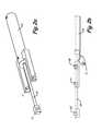
- FIG. 1is a side elevational view of the preferred embodiment of the present invention, shown in two positions.
- FIG. 2 ais a perspective view of the hydraulic cylinder of this invention.
- FIG. 2 bis a side view of the cylinder of FIG. 2 a.
- FIG. 3is a side view illustrating the geometric movement of an arm of the present invention.
- FIG. 4is a geometric diagram of the device shown in FIG. 3 .
- FIGS. 5 a and 5 billustrate a grasping device used in the present invention in a shaft engaging position and a shaft disengaging position respectively.
- a reel carrier device, 10generally, is adapted to be used with a vehicle such as a flat bed truck 11 , preferably with tandem axles 13 and a bed 15 as shown in the drawings.
- the truck 11is used to transport reels 17 of assorted sizes and construction that are common in the electric utility and telephone industries to carry cable material.
- a first work arm pair 19is forward of the end and a second work arm pair 21 is toward the back of the truck 11 , it being understood that the pair engages both ends of reels, as described below.
- Hydraulic double-acting cylinders 23 and pistons 25shown separate in FIGS. 2 a and 2 b , are mounted on the bed 15 and operate to move the pair of work arms 21 through an arc whereby the rear pair of arms 21 pick up a reel 17 from the ground or other place where it is at rest, such as a loading dock, warehouse or the like.
- Cylinder 63 and piston 65provide impetus to move a front reel forward.
- the end of work arm 21includes a reel engaging end 27 that engages spindle bar 29 .
- Reel engaging end 27is shown in the position in FIG. 1 where it has deposited a first reel 17 , which has been engaged by reel engaging end 31 of the first pair of work arms 19 , and moved that first reel to the front of the bed 15 .
- a standard jack stand 33shown lifted up for travel from pickup to delivery.
- Driving rolls 35 in truck bed 15can be powered to drive the reels in a rotation for light winding or unwinding.
- Support structure 37mounts the arms and cylinders.
- Work arm pair 21pass through an arc Y of about 160° to an open condition with piston 25 fully extended, shown at the end in FIG. 3 in solid line 21 and in dash lines 21 a , when hydraulic cylinder 23 pushes piston 25 out along the axis of piston 25 , also lifting cylinder 23 to the position shown in dash lines at 23 a for an angle arc X of 80° .
- pivot point Ais the cylinder 23 trunion mount
- pivot point Bis the cylinder ram to work arm location
- pivot point Cis the work arm 21 mount to the support structure
- pin Dconnects the lift column 39 to cylinder 23
- pin connection Econnects the lift column 39 to the work arm 21 .
- Points B, D, and Emove about points A and C, where point B moves linearly along the center line of cylinder 23 , and the cylinder angular travel up to 80° is always half of work arm travel up to 160°.
- lift arm 39 dimension Zis fixed during the first one half of the machine's angular travel, and then is free to extend, telescopically, for the second half of machine angular travel to the open state, doing no work in this second half.
- the function of lift arm 39is to bear the weight of the cylinder 23 and reel in that first half of angular travel.
- FIG. 4the relative dimensions of the elements in FIG. 3 are shown as a diagram.
- the lifting column 39is fixed in hole E of work arm 21 at one end and in hole D on the cylinder 23 .
- Column 39is shown as having a length z, which is, in one example, 18.6 inches.
- Line A-D angle ⁇ Xwhich is about 20°
- line C-Ethrough angle ⁇ Y, which is twice that or 40°.
- Both line A-D and line C-Ehave the same distance T, which is 5.3 inches in the example.
- FIG. 2 apoints A and B are shown with piston 25 extended from cylinder 25
- FIG. 2 bshows the distance of travel of point B from B 1 at cylinder 23 to full extension at B 2
- the distance between point A and point Bis twice R or, in the example, about twice six inches.
- Distance Sis, in the example, 18.46 inches, just a bit less than distance Z.
- FIGS. 5 a and 5 bAn improved grasping device is shown in open and closed positions in FIGS. 5 a and 5 b .
- a piston 41 and cylinder 43operate to move arm 45 and rotate jaw 47 so that the engaging element 51 of jaw 47 holds spindle bar 29 .
- Lever 53moves into engagement with lower end 55 of arm 45 to lockjaw 47 on spindle bar 29 , in FIG. 5 a , so that if hydraulic pressure in cylinder 43 fails, the device will still hold the spindle bar 29 and, thus, a reel on spindle bar 29 will not escape to cause damage.
Landscapes
- Engineering & Computer Science (AREA)
- Transportation (AREA)
- Mechanical Engineering (AREA)
- Health & Medical Sciences (AREA)
- Public Health (AREA)
- Handcart (AREA)
- Replacing, Conveying, And Pick-Finding For Filamentary Materials (AREA)
- Forklifts And Lifting Vehicles (AREA)
Abstract
Description
Claims (6)
Priority Applications (1)
| Application Number | Priority Date | Filing Date | Title |
|---|---|---|---|
| US12/286,440US8021097B2 (en) | 2007-10-15 | 2008-09-30 | Loading and unloading reel carrier truck |
Applications Claiming Priority (2)
| Application Number | Priority Date | Filing Date | Title |
|---|---|---|---|
| US99904207P | 2007-10-15 | 2007-10-15 | |
| US12/286,440US8021097B2 (en) | 2007-10-15 | 2008-09-30 | Loading and unloading reel carrier truck |
Publications (2)
| Publication Number | Publication Date |
|---|---|
| US20090097951A1 US20090097951A1 (en) | 2009-04-16 |
| US8021097B2true US8021097B2 (en) | 2011-09-20 |
Family
ID=40534383
Family Applications (1)
| Application Number | Title | Priority Date | Filing Date |
|---|---|---|---|
| US12/286,440Active2029-07-03US8021097B2 (en) | 2007-10-15 | 2008-09-30 | Loading and unloading reel carrier truck |
Country Status (2)
| Country | Link |
|---|---|
| US (1) | US8021097B2 (en) |
| CA (1) | CA2640928C (en) |
Cited By (15)
| Publication number | Priority date | Publication date | Assignee | Title |
|---|---|---|---|---|
| US20120118397A1 (en)* | 2010-11-16 | 2012-05-17 | Tetra Technologies, Inc. | Rapid Deployment Frac Water Transfer System |
| US8998959B2 (en) | 2009-06-15 | 2015-04-07 | Roger P Jackson | Polyaxial bone anchors with pop-on shank, fully constrained friction fit retainer and lock and release insert |
| US20150158692A1 (en)* | 2013-12-06 | 2015-06-11 | Western Technology Services International, Inc. | Cable Drum Transportation and Handling Apparatus |
| US9393047B2 (en) | 2009-06-15 | 2016-07-19 | Roger P. Jackson | Polyaxial bone anchor with pop-on shank and friction fit retainer with low profile edge lock |
| US9907574B2 (en) | 2008-08-01 | 2018-03-06 | Roger P. Jackson | Polyaxial bone anchors with pop-on shank, friction fit fully restrained retainer, insert and tool receiving features |
| US9918745B2 (en) | 2009-06-15 | 2018-03-20 | Roger P. Jackson | Polyaxial bone anchor with pop-on shank and winged insert with friction fit compressive collet |
| US9980753B2 (en) | 2009-06-15 | 2018-05-29 | Roger P Jackson | pivotal anchor with snap-in-place insert having rotation blocking extensions |
| US10000358B2 (en) | 2010-11-16 | 2018-06-19 | Tetra Technologies, Inc. | Rapid deployment frac water transfer system |
| US10150402B2 (en) | 2016-04-08 | 2018-12-11 | Trinity Bay Equipment Holdings, LLC | Pipe deployment trailer |
| US10194951B2 (en) | 2005-05-10 | 2019-02-05 | Roger P. Jackson | Polyaxial bone anchor with compound articulation and pop-on shank |
| US10363070B2 (en) | 2009-06-15 | 2019-07-30 | Roger P. Jackson | Pivotal bone anchor assemblies with pressure inserts and snap on articulating retainers |
| US10654395B1 (en) | 2016-04-08 | 2020-05-19 | Trinity Bay Equipment Holdings, LLC | Pipe deployment trailer |
| US10746587B1 (en)* | 2020-05-11 | 2020-08-18 | Altec Industries, Inc. | System and method for determining a reel weight on a reel-carrying unit |
| US10745237B2 (en) | 2017-03-30 | 2020-08-18 | Triple C Manufacturing, Inc. | Hydraulic truck bed reel lift apparatus |
| US20250197159A1 (en)* | 2023-12-14 | 2025-06-19 | Albert Ben Currey | Spool transporter |
Families Citing this family (1)
| Publication number | Priority date | Publication date | Assignee | Title |
|---|---|---|---|---|
| CN100406102C (en) | 2002-10-28 | 2008-07-30 | 唐纳森公司 | Air cleaner, replaceable filter cartridge and method of making the same |
Citations (8)
| Publication number | Priority date | Publication date | Assignee | Title |
|---|---|---|---|---|
| US3184082A (en) | 1963-09-26 | 1965-05-18 | Fred C Hall | Reel loader |
| US3325118A (en) | 1964-10-20 | 1967-06-13 | Fred C Hall | Cable reel drive mechanism |
| US3820673A (en) | 1972-06-05 | 1974-06-28 | Champion Corp | Loading and unloading means for cable reels and other structures |
| US4228967A (en) | 1979-09-19 | 1980-10-21 | Champion Corporation | Reel loader construction |
| US4591309A (en) | 1984-01-30 | 1986-05-27 | Champion Corporation | Dual-reel loader construction |
| US5123602A (en) | 1989-10-31 | 1992-06-23 | Skaltek Ab | Machine for winding cables or the like on or off a drum |
| US5897073A (en) | 1996-08-05 | 1999-04-27 | Mcvaugh; Arthur K. | Reel handler |
| US6467715B2 (en)* | 2000-06-14 | 2002-10-22 | Dong-Hae Corporation | Overhead power line installation apparatus |
- 2008
- 2008-09-30USUS12/286,440patent/US8021097B2/enactiveActive
- 2008-10-14CACA2640928Apatent/CA2640928C/enactiveActive
Patent Citations (8)
| Publication number | Priority date | Publication date | Assignee | Title |
|---|---|---|---|---|
| US3184082A (en) | 1963-09-26 | 1965-05-18 | Fred C Hall | Reel loader |
| US3325118A (en) | 1964-10-20 | 1967-06-13 | Fred C Hall | Cable reel drive mechanism |
| US3820673A (en) | 1972-06-05 | 1974-06-28 | Champion Corp | Loading and unloading means for cable reels and other structures |
| US4228967A (en) | 1979-09-19 | 1980-10-21 | Champion Corporation | Reel loader construction |
| US4591309A (en) | 1984-01-30 | 1986-05-27 | Champion Corporation | Dual-reel loader construction |
| US5123602A (en) | 1989-10-31 | 1992-06-23 | Skaltek Ab | Machine for winding cables or the like on or off a drum |
| US5897073A (en) | 1996-08-05 | 1999-04-27 | Mcvaugh; Arthur K. | Reel handler |
| US6467715B2 (en)* | 2000-06-14 | 2002-10-22 | Dong-Hae Corporation | Overhead power line installation apparatus |
Cited By (18)
| Publication number | Priority date | Publication date | Assignee | Title |
|---|---|---|---|---|
| US10194951B2 (en) | 2005-05-10 | 2019-02-05 | Roger P. Jackson | Polyaxial bone anchor with compound articulation and pop-on shank |
| US9907574B2 (en) | 2008-08-01 | 2018-03-06 | Roger P. Jackson | Polyaxial bone anchors with pop-on shank, friction fit fully restrained retainer, insert and tool receiving features |
| US9393047B2 (en) | 2009-06-15 | 2016-07-19 | Roger P. Jackson | Polyaxial bone anchor with pop-on shank and friction fit retainer with low profile edge lock |
| US9918745B2 (en) | 2009-06-15 | 2018-03-20 | Roger P. Jackson | Polyaxial bone anchor with pop-on shank and winged insert with friction fit compressive collet |
| US10363070B2 (en) | 2009-06-15 | 2019-07-30 | Roger P. Jackson | Pivotal bone anchor assemblies with pressure inserts and snap on articulating retainers |
| US8998959B2 (en) | 2009-06-15 | 2015-04-07 | Roger P Jackson | Polyaxial bone anchors with pop-on shank, fully constrained friction fit retainer and lock and release insert |
| US9980753B2 (en) | 2009-06-15 | 2018-05-29 | Roger P Jackson | pivotal anchor with snap-in-place insert having rotation blocking extensions |
| US10000358B2 (en) | 2010-11-16 | 2018-06-19 | Tetra Technologies, Inc. | Rapid deployment frac water transfer system |
| US9371723B2 (en)* | 2010-11-16 | 2016-06-21 | Tetra Technologies, Inc. | Rapid deployment frac water transfer system |
| US9790776B2 (en) | 2010-11-16 | 2017-10-17 | Tetra Technologies, Inc. | Rapid deployment frac water transfer system |
| US20120118397A1 (en)* | 2010-11-16 | 2012-05-17 | Tetra Technologies, Inc. | Rapid Deployment Frac Water Transfer System |
| US20150158692A1 (en)* | 2013-12-06 | 2015-06-11 | Western Technology Services International, Inc. | Cable Drum Transportation and Handling Apparatus |
| US10106370B2 (en)* | 2013-12-06 | 2018-10-23 | Western Technology Services International, Inc. | Cable drum transportation and handling apparatus |
| US10150402B2 (en) | 2016-04-08 | 2018-12-11 | Trinity Bay Equipment Holdings, LLC | Pipe deployment trailer |
| US10654395B1 (en) | 2016-04-08 | 2020-05-19 | Trinity Bay Equipment Holdings, LLC | Pipe deployment trailer |
| US10745237B2 (en) | 2017-03-30 | 2020-08-18 | Triple C Manufacturing, Inc. | Hydraulic truck bed reel lift apparatus |
| US10746587B1 (en)* | 2020-05-11 | 2020-08-18 | Altec Industries, Inc. | System and method for determining a reel weight on a reel-carrying unit |
| US20250197159A1 (en)* | 2023-12-14 | 2025-06-19 | Albert Ben Currey | Spool transporter |
Also Published As
| Publication number | Publication date |
|---|---|
| US20090097951A1 (en) | 2009-04-16 |
| CA2640928C (en) | 2016-01-26 |
| CA2640928A1 (en) | 2009-04-15 |
Similar Documents
| Publication | Publication Date | Title |
|---|---|---|
| US8021097B2 (en) | Loading and unloading reel carrier truck | |
| US4645405A (en) | Roll-off container handling mechanism | |
| US7494087B2 (en) | Reel handler | |
| MX2014014916A (en) | Cable drum transportation and handling apparatus. | |
| CN110668362B (en) | A manual forklift with a folding forklift | |
| US3235105A (en) | Vehicle | |
| US4128179A (en) | Bale loader | |
| US2506242A (en) | Vehicle mounted crane with load lifting accessory | |
| US20220127118A1 (en) | Vehicle mounted fork lift and method | |
| CN214087548U (en) | Turnover forklift convenient to carry | |
| CN115744741A (en) | Transport fork truck capable of loading multiple goods | |
| US4600350A (en) | Method and apparatus for handling container chassis | |
| US20110318148A1 (en) | Cable reeving system for lifting and loading | |
| JPH11503101A (en) | Mechanisms for loading and unloading containers from vehicles | |
| US3335879A (en) | Side carrying lift truck | |
| CN104338794B (en) | Cold-rolling mill automatic on unload sleeve and sleeve transport single unit system | |
| US20130084152A1 (en) | Container Loading System | |
| CN204074813U (en) | Cold-rolling mill automatic on unload sleeve and sleeve transport single unit system | |
| US4591309A (en) | Dual-reel loader construction | |
| JP3238018B2 (en) | Forklift handling equipment | |
| CN112208609A (en) | Logistics transport vehicle | |
| KR100468193B1 (en) | Horizontal Planting Loading and Unloading Device for a Lorry | |
| CN112173699A (en) | Using method of logistics transport vehicle | |
| US3384255A (en) | Lift attachment for handling cylindrical objects | |
| US20240417229A1 (en) | Forklift part flipper attachment |
Legal Events
| Date | Code | Title | Description |
|---|---|---|---|
| AS | Assignment | Owner name:DEJANA TRUCK & UTILITY EQUIPMENT CO., NEW YORK Free format text:ASSIGNMENT OF ASSIGNORS INTEREST;ASSIGNOR:MCVAUGH, ARTHUR K.;REEL/FRAME:021681/0418 Effective date:20080923 | |
| STCF | Information on status: patent grant | Free format text:PATENTED CASE | |
| CC | Certificate of correction | ||
| FPAY | Fee payment | Year of fee payment:4 | |
| SULP | Surcharge for late payment | ||
| AS | Assignment | Owner name:JPMORGAN CHASE BANK, N.A., AS COLLATERAL AGENT, IL Free format text:PATENT SECURITY AGREEMENT (ABL);ASSIGNOR:ACQUISITION DELTA LLC;REEL/FRAME:039390/0247 Effective date:20160715 Owner name:JPMORGAN CHASE BANK, N.A., AS COLLATERAL AGENT, IL Free format text:PATENT SECURITY AGREEMENT (TERM LOAN);ASSIGNOR:ACQUISITION DELTA LLC;REEL/FRAME:039390/0260 Effective date:20160715 | |
| AS | Assignment | Owner name:ACQUISITION DELTA LLC, WISCONSIN Free format text:ASSIGNMENT OF ASSIGNORS INTEREST;ASSIGNOR:DEJANA TRUCK & UTILITY EQUIPMENT COMPANY, INC.;REEL/FRAME:039274/0782 Effective date:20160715 Owner name:DEJANA TRUCK & UTILITY EQUIPMENT COMPANY, LLC, WIS Free format text:CHANGE OF NAME;ASSIGNOR:ACQUISITION DELTA LLC;REEL/FRAME:039492/0903 Effective date:20160715 | |
| MAFP | Maintenance fee payment | Free format text:PAYMENT OF MAINTENANCE FEE, 8TH YR, SMALL ENTITY (ORIGINAL EVENT CODE: M2552); ENTITY STATUS OF PATENT OWNER: SMALL ENTITY Year of fee payment:8 | |
| AS | Assignment | Owner name:ACQUISITION DELTA LLC, WISCONSIN Free format text:RELEASE OF SECURITY INTEREST IN PATENTS PREVIOUSLY RECORDED AT REEL/FRAME (039390/0247);ASSIGNOR:JPMORGAN CHASE BANK, N.A., AS COLLATERAL AGENT;REEL/FRAME:056676/0500 Effective date:20210609 Owner name:ACQUISITION DELTA LLC, WISCONSIN Free format text:RELEASE OF SECURITY INTEREST IN PATENTS PREVIOUSLY RECORDED AT REEL/FRAME (039390/0260);ASSIGNOR:JPMORGAN CHASE BANK, N.A., AS COLLATERAL AGENT;REEL/FRAME:056676/0506 Effective date:20210609 Owner name:ACQUISITION DELTA LLC, WISCONSIN Free format text:RELEASE OF SECURITY INTEREST IN PATENTS PREVIOUSLY RECORDED AT REEL/FRAME (046379/0793);ASSIGNOR:JPMORGAN CHASE BANK, N.A., AS COLLATERAL AGENT;REEL/FRAME:056676/0536 Effective date:20210609 Owner name:ACQUISITION DELTA LLC, WISCONSIN Free format text:RELEASE OF SECURITY INTEREST IN PATENTS PREVIOUSLY RECORDED AT REEL/FRAME (044015/0018);ASSIGNOR:JPMORGAN CHASE BANK, N.A., AS COLLATERAL AGENT;REEL/FRAME:056676/0563 Effective date:20210609 Owner name:ACQUISITION DELTA LLC, WISCONSIN Free format text:RELEASE OF SECURITY INTEREST IN PATENTS PREVIOUSLY RECORDED AT REEL/FRAME (044015/0101);ASSIGNOR:JPMORGAN CHASE BANK, N.A., AS COLLATERAL AGENT;REEL/FRAME:056676/0572 Effective date:20210609 Owner name:ACQUISITION DELTA LLC, WISCONSIN Free format text:RELEASE OF SECURITY INTEREST IN PATENTS PREVIOUSLY RECORDED AT REEL/FRAME (046379/0837);ASSIGNOR:JPMORGAN CHASE BANK, N.A., AS COLLATERAL AGENT;REEL/FRAME:056676/0578 Effective date:20210609 | |
| AS | Assignment | Owner name:JPMORGAN CHASE BANK, N.A., AS ADMINISTRATIVE AGENT, ILLINOIS Free format text:SECURITY INTEREST;ASSIGNORS:DOUGLAS DYNAMICS, L.L.C.;TRYNEX INTERNATIONAL LLC;HENDERSON PRODUCTS, INC.;AND OTHERS;REEL/FRAME:056538/0901 Effective date:20210609 | |
| MAFP | Maintenance fee payment | Free format text:PAYMENT OF MAINTENANCE FEE, 12TH YR, SMALL ENTITY (ORIGINAL EVENT CODE: M2553); ENTITY STATUS OF PATENT OWNER: SMALL ENTITY Year of fee payment:12 | |
| FEPP | Fee payment procedure | Free format text:ENTITY STATUS SET TO UNDISCOUNTED (ORIGINAL EVENT CODE: BIG.); ENTITY STATUS OF PATENT OWNER: LARGE ENTITY |