US8020441B2 - Dual mode sensing for vibratory gyroscope - Google Patents
Dual mode sensing for vibratory gyroscopeDownload PDFInfo
- Publication number
- US8020441B2 US8020441B2US12/026,490US2649008AUS8020441B2US 8020441 B2US8020441 B2US 8020441B2US 2649008 AUS2649008 AUS 2649008AUS 8020441 B2US8020441 B2US 8020441B2
- Authority
- US
- United States
- Prior art keywords
- subsystem
- sense
- drive
- axis
- mass
- Prior art date
- Legal status (The legal status is an assumption and is not a legal conclusion. Google has not performed a legal analysis and makes no representation as to the accuracy of the status listed.)
- Active, expires
Links
- 230000009977dual effectEffects0.000title1
- 239000000758substrateSubstances0.000claimsabstractdescription35
- 230000004044responseEffects0.000claimsabstractdescription3
- 230000008878couplingEffects0.000claimsdescription12
- 238000010168coupling processMethods0.000claimsdescription12
- 238000005859coupling reactionMethods0.000claimsdescription12
- 230000010355oscillationEffects0.000claimsdescription7
- 238000012546transferMethods0.000description13
- 238000013461designMethods0.000description5
- 230000035945sensitivityEffects0.000description5
- 239000006096absorbing agentSubstances0.000description4
- 238000004873anchoringMethods0.000description2
- 230000007246mechanismEffects0.000description2
- 238000000034methodMethods0.000description2
- 238000012986modificationMethods0.000description2
- 230000004048modificationEffects0.000description2
- 230000009467reductionEffects0.000description2
- 238000000926separation methodMethods0.000description2
- 238000013519translationMethods0.000description2
- 230000005653Brownian motion processEffects0.000description1
- 239000008186active pharmaceutical agentSubstances0.000description1
- 230000002411adverseEffects0.000description1
- 238000005537brownian motionMethods0.000description1
- 230000002452interceptive effectEffects0.000description1
- 238000001228spectrumMethods0.000description1
Images


Classifications
- G—PHYSICS
- G01—MEASURING; TESTING
- G01C—MEASURING DISTANCES, LEVELS OR BEARINGS; SURVEYING; NAVIGATION; GYROSCOPIC INSTRUMENTS; PHOTOGRAMMETRY OR VIDEOGRAMMETRY
- G01C19/00—Gyroscopes; Turn-sensitive devices using vibrating masses; Turn-sensitive devices without moving masses; Measuring angular rate using gyroscopic effects
- G01C19/56—Turn-sensitive devices using vibrating masses, e.g. vibratory angular rate sensors based on Coriolis forces
- G01C19/5719—Turn-sensitive devices using vibrating masses, e.g. vibratory angular rate sensors based on Coriolis forces using planar vibrating masses driven in a translation vibration along an axis
Definitions
- the present inventionrelates to a vibratory gyroscope and more particularly to a drive and sense subsystems formed within such a gyroscope.
- the angular rate sensorcomprises a substrate and a drive subsystem partially supported by a substrate.
- the drive subsystemincludes at least one spring, at least one anchor, and at least one mass; the at least one mass of the drive subsystem is oscillated by at least one actuator along a first axis.
- the Coriolis forceacts on the drive subsystem along or around a second axis in response to angular velocity of the substrate around the third axis.
- the angular rate sensoralso includes a sense subsystem partially supported by a substrate.
- the sense subsystemincludes at least one spring, at least one anchor, and at least one mass.
- the sense subsystemmoves along or around the fourth axis; and the motion of the sense subsystem can be sensed by a transducer and is proportional to the rate of rotation of a substrate about a third axis.
- the angular rate sensorcomprises a flexible coupling between the drive subsystem and the sense subsystem.
- FIG. 1Ashows the angular rate sensor comprising drive and sense subsystems, and a substrate.
- FIG. 1Bdepicts the disclosed sensing method comprising flexibly-coupled drive and sense subsystems.
- FIG. 1Cdepicts uncoupled drive and sense subsystems characterized by an uncoupled drive and an uncoupled sense resonant modes, respectively.
- FIG. 2Ashows an amplitude-frequency characteristic of transfer functions G SD and G DS .
- FIG. 2Bshows an amplitude frequency characteristic of transfer functions G SS and G DD .
- FIG. 3shows drive and sense subsystems comprising complex mass-spring systems and reduction of such complex system into a simple two mass sense system.
- FIG. 4Ashows one implementation in accordance with the present invention.
- FIG. 4Bshows reduction of the embodiment from FIG. 4A into the two mass system.
- FIG. 5shows a mechanism of transfer of Coriolis force to the sense mass, i.e., torque acting on drive system cause only sense system to rotate.
- the present inventionrelates generally to a drive and sense subsystems formed within a device layer, and a substrate.
- the following descriptionis presented to enable one of ordinary skill in the art to make and use the invention and is provided in the context of a patent application and its requirements.
- Various modifications to the preferred embodiment and the generic principles and features described hereinwill be readily apparent to those skilled in the art.
- the present inventionis not intended to be limited to the embodiment shown but is to be accorded the widest scope consistent with the principles and features described herein.
- the angular rate sensorcomprises drive and sense subsystems, and a substrate.
- the drive and sense subsystems 1002 and 1004respectively are supported by the substrate 1250 through anchor points, and the drive and sense subsystems 1002 and 1004 are flexibly coupled.
- the drive subsystem 1002may include mass 1102 which could be one or more separate masses and the sense subsystem 1004 may include mass 1101 which could be one or more separate masses.
- the drive subsystem 1002may be oscillated at a frequency ⁇ along a first axis by an actuator. Coriolis forces F coriolis may be generated on the drive subsystem 1002 along or around a second axis if the substrate 1250 rotates around a third axis.
- the Coriolis forces F coriolismay be transferred to the sense subsystem 1004 through the flexible coupling 1202 and cause the sense subsystem 1004 to move along or around the fourth axis. Motion of the sense subsystem 1004 may be sensed with an appropriate transducer, and its amplitude may be proportional to the rate of rotation of the substrate 1250 . Further, another force, such as mechanical noise F noise , may act on the sense subsystem 1004 thus interfering with sensing of the rate of rotation of the substrate 1250 .
- the following analysisdescribes how Coriolis force and noise are transferred from the drive 1002 to the sense subsystem 1004 and vice-versa.
- the basic systemcomprising drive mass 1102 and sense mass 1101 , drive flexure 1203 and sense flexure 1201 , and a flexible coupling 1202 between masses 1102 and 1101 .
- This basic systemdiscloses all benefits of the sensing scheme, in particular, more efficient transfer of Coriolis forces to the sense motion and rejection of the mechanical noise F noise generated on the sense subsystem 1004 .
- the analysiscontinues to extend the sensing scheme to the case where drive and sense subsystems comprise a plurality of masses and springs.
- the first embodimentis capable of sensing the rotation of the substrate 1250 around the axis parallel to the substrate 1250 and is commonly known as X- or Y-axis angular rate sensor
- the second embodimentis capable of sensing the rotation of the substrate 1250 around the axis normal to the substrate 1250 and is commonly known as Z axis angular rate sensor.
- mass-translation terminologyis disclosed herein. However, the analysis is not limited to mass-translation only but is equally valid for moment-of-inertia-rotation terminology, as well as for the combination thereof.
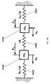
- FIG. 1Bdepicts the disclosed sensing method comprising flexibly-coupled drive and sense subsystems 1002 and 1004
- the sense subsystem 1004comprises mass m S 1101 , a sense spring 1201 with stiffness k S ⁇ k, and a coupling spring with stiffness ⁇ k 1202 .
- the drive subsystemcomprises mass m D 1102 , a drive spring 1203 with stiffness k D ⁇ k, and a coupling spring with stiffness ⁇ k.
- the sense mass m S 1101is suspended from the substrate by the sense spring 1201 while the drive mass m D 1102 is suspended from the substrate by the drive spring 1203 .
- the sense mass m S 1101 and the drive mass m D 1102are flexibly coupled through a spring 1202 with stiffness ⁇ k such that both stiffness k S ⁇ k and stiffness k D ⁇ k are greater than zero, i.e. k S ⁇ k>0 and k D ⁇ k>0.
- the sensing system from FIG. 1Byields a total of four transfer functions whose inputs are generalized forces F S and F D and outputs are motion of the particular mass, x S or x D .
- ⁇ S1 and ⁇ S2are modal frequencies assigned to two vibratory modes of the system from FIG. 1B .
- ⁇ S1 and ⁇ S2are modal frequencies assigned to two vibratory modes of the system from FIG. 1B .
- the relationship between the position of the drive mass 1102 , x d , and force acting on the sense mass 1101 , F Scan be expressed as a yet another transfer function:
- G DDhas an anti-resonance ⁇ S , defined as a sense resonant mode of the uncoupled sense subsystem
- G SShas anti-resonance ⁇ D , defined as a drive resonant mode of the uncoupled drive subsystem.
- FIG. 2AAn amplitude-frequency characteristic of transfer functions G SD and G DS is shown in FIG. 2A
- amplitude frequency characteristic of transfer functions G SS and G DDis shown in FIG. 2B
- resonant peak 1501is defined by resonant frequency ⁇ S1
- peak 1502is defined by resonant frequency ⁇ S2 .
- the difference between ⁇ S2 and ⁇ S1is shown in FIG. 2A as 1510 .
- Anti-resonance 1503 in FIG. 2 bis defined either by ⁇ S or ⁇ D , depending whether transfer function G DD or G SS is considered.
- the drive mass 1102may be oscillated at frequency ⁇ 0 such that drive force F D acting on the drive mass 1102 may be Coriolis force or torque.
- position x Smay be measured and its amplitude may be proportional to the rate of rotation of the substrate 1250 .
- force F Smay act on sense mass 1101 , and force F S may be induced by the mechanical noise such as Brownian motion.
- frequency ⁇is the frequency at which the Coriolis force modulates onto the mass 1102 the sensitivity of the sensor is proportional to the gain of the amplitude frequency characteristics at frequency ⁇ 0 ( 1520 ), as shown in FIG. 2A .
- the Coriolis force acting on the drive mass 1102generates motion at x S without moving x D at all.
- Drive mass 1102only transfers force to sense mass 1101 . Consequently, energy of oscillations caused by the Coriolis force is not used to oscillate drive mass 1102 but is all used to oscillate sense mass 1101 . This improves sensitivity.
- the sense subsystem 1004acts as a vibration absorber for the drive system 1002 at the frequency of drive oscillations. Further, referring to FIG. 1B and FIG.
- the drive subsystem 1002acts as a vibration absorber for the sense system 1004 at the frequency of drive oscillations, therefore rejecting the noise-induced motion of the sense subsystem 1004 .
- Both anti-resonant frequencies, ⁇ S and ⁇ Dmay be made substantially equal to the frequency of drive oscillations ⁇ 0 by adjusting stiffness of the sense 1004 and the drive 1002 system's springs, k S and k D . If ⁇ S and ⁇ D are substantially equal to ⁇ 0 , frequencies ⁇ S1 and ⁇ S2 may be calculated as:
- the flexible coupling ⁇ k 1202defines separation between ⁇ S2 and ⁇ S1 1510 .
- Coupling stiffness ⁇ k 1202may be substantially large in order to separate peaks, yielding wider sensor bandwidth.
- coupling stiffness ⁇ k 1202may be substantially small to keep peaks close enough in order to achieve high transducer gain.
- three tunable design parameters, k S , k D , and ⁇ kare available to independently adjust two anti-resonances, ⁇ S and ⁇ D , as well as separation between resonant frequencies ⁇ S2 and ⁇ S1 , therefore providing high design flexibility in terms of choice of operational frequency ⁇ 0 , sensitivity and bandwidth.
- the drive subsystem 1002may comprise a plurality of masses, a plurality of springs and a plurality of anchors and the sense subsystem 1004 may comprise a plurality of masses, a plurality of springs and a plurality of anchors. Consequently, the uncoupled drive subsystem 1002 may have a plurality of vibratory modes and the uncoupled sense subsystem 1004 may have a plurality of vibratory modes.
- One of the vibratory modes of the uncoupled sense subsystem 1004may have resonant frequency ⁇ S and one of the vibratory modes of uncoupled drive subsystem may have resonant frequency ⁇ D , and both ⁇ S and ⁇ D may be substantially close to ⁇ 0 .
- the systemhas at least two resonant modes with frequencies ⁇ S2 and ⁇ S1 .
- the drive subsystem 1002may have at least one mass, m′ D , flexibly coupled to the sense subsystem 1004 and the sense subsystem 1004 may have at least one mass, m′ S , flexibly coupled to the drive subsystem 1002 .
- FIG. 3it is possible to model the drive system 1002 and forces acting upon it with a single mass 1102 , a single spring 1203 , a single anchor and a single force acting on the mass 1102 .
- sense system 1004 and forces acting upon itcan be modeled with a single mass 1101 , a single spring 1201 , a single anchor and a single force acting on the mass 1101 .
- the coupled sensing system from FIG. 3can be represented with the simple two-mass, three-spring system such that the uncoupled drive frequency, ⁇ D , uncoupled sense frequency, ⁇ S , and frequencies of the coupled system, ⁇ S2 and ⁇ S1 , are the same.
- drive and sense subsystemsmay be formed within the device layer which is parallel to the substrate and a plane.
- the drive subsystemcomprises masses 10 a , 10 b , 20 , 30 a and 30 b and spring systems 50 , 70 and 80 .
- the drive systemis supported by the substrate at anchoring points 90 a and 90 b and spring systems 70 a and 70 b .
- the sense subsystemcomprises single mass 200 and plurality of springs 210 a - d suspending the sense subsystem to the substrate through the anchoring points 220 a - d .
- the drive and the sense subsystemsare flexibly coupled through spring system 60 . Referring to FIG. 4 b , and according to teaching related to FIG.
- the drive subsystemmay be lumped such that the rotation of the mass 20 , ⁇ C , represents total motion of the drive subsystem around the Z axis.
- the sense subsystemmay be lumped such that the rotation of the mass 200 , ⁇ R , represents total motion of the sense subsystem round the Z axis. The whole system reduces to the simple, flexible-coupled, two-mass system already analyzed and related to FIG. 1B .
- proof masses 10 a and 10 bmay be oscillated at frequency ⁇ 0 in anti-phase fashion along the Z-axis. If the substrate rotates around the Y axis, the Coriolis force acts on proof masses 10 a and 10 b along the X axis in opposite direction therefore generating torque around the Z-axis. Generated torque is transferred to inertia 20 and to the sense subsystem's mass 200 through spring system 60 causing rotation of the sense mass with amplitude proportional to the input rate of rotation around Y axis, Rotation of the sense subsystem may be sensed by appropriate transducer 400 .
- the proof masses 10 a and 10 bmay be oscillated at frequency ⁇ 0 along Y-axis in anti-phase fashion. If the substrate rotates around the Z axis, the Coriolis force acts on proof masses 10 a and 10 b along the X axis in opposite direction therefore generating torque around the Z-axis. Generated torque is transferred to mass 20 and further to the mass 200 through spring system 60 causing rotation of the sense subsystem with amplitude proportional to the input rate of rotation around Z-axis. Rotation of the sense subsystem may be sensed by appropriate transducer 400 .
- FIG. 5a mechanism of transfer of Coriolis force to the sense mass, i.e. ring, is shown in greater detail.
- the sense subsystemacts as a vibration absorber for the drive subsystem
- the Coriolis force generated at drive systemis only transferred through the drive system to the sense subsystem.
- the drive subsystemdoes not move while the sense subsystem rotates. This way, Coriolis force is used only to rotate the sense subsystem therefore improving sensitivity of the sensor.
- any torque generated on the sense subsystemsuch as Brownian noise, moves only the drive subsystem. Therefore, the noise acting on the sense subsystem is reduced significantly.
Landscapes
- Physics & Mathematics (AREA)
- Engineering & Computer Science (AREA)
- General Physics & Mathematics (AREA)
- Radar, Positioning & Navigation (AREA)
- Remote Sensing (AREA)
- Gyroscopes (AREA)
Abstract
Description
The present invention relates to a vibratory gyroscope and more particularly to a drive and sense subsystems formed within such a gyroscope.
In vibratory gyroscopes with two sense peak structures, conventional designs require sense masses to be split in order to achieve two mode dynamics [Acar et al., U.S. Pat. No. 6,845,669]. Additionally, in conventional systems in the two sense peak design, the sense masses are never anchored [Acar et al., U.S. Pat. No. 6,845,669]. Accordingly, a problem with conventional systems is that they may not be sensitive enough in some applications and may also produce a high amount of mechanical noise to adversely affect the sensing capability of the gyroscope.
Accordingly what is needed is a vibrating gyroscope and a system that overcomes these issues. The present invention addresses such a need.
An angular rate sensor is disclosed. The angular rate sensor comprises a substrate and a drive subsystem partially supported by a substrate. The drive subsystem includes at least one spring, at least one anchor, and at least one mass; the at least one mass of the drive subsystem is oscillated by at least one actuator along a first axis. The Coriolis force acts on the drive subsystem along or around a second axis in response to angular velocity of the substrate around the third axis. The angular rate sensor also includes a sense subsystem partially supported by a substrate. The sense subsystem includes at least one spring, at least one anchor, and at least one mass. The sense subsystem moves along or around the fourth axis; and the motion of the sense subsystem can be sensed by a transducer and is proportional to the rate of rotation of a substrate about a third axis. Finally, the angular rate sensor comprises a flexible coupling between the drive subsystem and the sense subsystem.
The present invention relates generally to a drive and sense subsystems formed within a device layer, and a substrate. The following description is presented to enable one of ordinary skill in the art to make and use the invention and is provided in the context of a patent application and its requirements. Various modifications to the preferred embodiment and the generic principles and features described herein will be readily apparent to those skilled in the art. Thus, the present invention is not intended to be limited to the embodiment shown but is to be accorded the widest scope consistent with the principles and features described herein.
General Structure of the Angular Rate Sensor
Referring to theFIG. 1A , the angular rate sensor comprises drive and sense subsystems, and a substrate. The drive andsense subsystems substrate 1250 through anchor points, and the drive andsense subsystems drive subsystem 1002 may includemass 1102 which could be one or more separate masses and thesense subsystem 1004 may includemass 1101 which could be one or more separate masses. Thedrive subsystem 1002 may be oscillated at a frequency ω along a first axis by an actuator. Coriolis forces Fcoriolismay be generated on thedrive subsystem 1002 along or around a second axis if thesubstrate 1250 rotates around a third axis. The Coriolis forces Fcoriolismay be transferred to thesense subsystem 1004 through theflexible coupling 1202 and cause thesense subsystem 1004 to move along or around the fourth axis. Motion of thesense subsystem 1004 may be sensed with an appropriate transducer, and its amplitude may be proportional to the rate of rotation of thesubstrate 1250. Further, another force, such as mechanical noise Fnoise, may act on thesense subsystem 1004 thus interfering with sensing of the rate of rotation of thesubstrate 1250.
The following analysis describes how Coriolis force and noise are transferred from thedrive 1002 to thesense subsystem 1004 and vice-versa. First, referring toFIG. 1B , the basic system, comprisingdrive mass 1102 andsense mass 1101, driveflexure 1203 andsense flexure 1201, and aflexible coupling 1202 betweenmasses sense subsystem 1004. Further, the analysis continues to extend the sensing scheme to the case where drive and sense subsystems comprise a plurality of masses and springs. Further yet, two particular angular rate sensor embodiments applying the disclosed sensing scheme are addressed. The first embodiment is capable of sensing the rotation of thesubstrate 1250 around the axis parallel to thesubstrate 1250 and is commonly known as X- or Y-axis angular rate sensor, and the second embodiment is capable of sensing the rotation of thesubstrate 1250 around the axis normal to thesubstrate 1250 and is commonly known as Z axis angular rate sensor.
In addition, a mass-translation terminology is disclosed herein. However, the analysis is not limited to mass-translation only but is equally valid for moment-of-inertia-rotation terminology, as well as for the combination thereof.
Sensing System
The relationship between the position of thesense mass x S1101, xS, and force acting on thedrive mass 1102, FD, can be expressed as the following transfer function:
where ωS1and ωS2are modal frequencies assigned to two vibratory modes of the system from
Further, the relationship between the position of, and the force acting on either drive mass mD1102 orsense mass m S1101 can be expressed with the following transfer functions:
where GDDhas an anti-resonance ωS, defined as a sense resonant mode of the uncoupled sense subsystem and GSShas anti-resonance ωD, defined as a drive resonant mode of the uncoupled drive subsystem.
An amplitude-frequency characteristic of transfer functions GSDand GDSis shown inFIG. 2A , and amplitude frequency characteristic of transfer functions GSSand GDDis shown inFIG. 2B . In bothFIG. 2A andFIG. 2B resonant peak 1501 is defined by resonant frequency ωS1and peak1502 is defined by resonant frequency ωS2. The difference between ωS2and ωS1is shown inFIG. 2A as1510.Anti-resonance 1503 inFIG. 2 bis defined either by ωSor ωD, depending whether transfer function GDDor GSSis considered. Further, thedrive mass 1102 may be oscillated at frequency ω0such that drive force FDacting on thedrive mass 1102 may be Coriolis force or torque. Also, position xSmay be measured and its amplitude may be proportional to the rate of rotation of thesubstrate 1250. Also, force FSmay act onsense mass 1101, and force FSmay be induced by the mechanical noise such as Brownian motion. As frequency ω is the frequency at which the Coriolis force modulates onto themass 1102 the sensitivity of the sensor is proportional to the gain of the amplitude frequency characteristics at frequency ω0(1520), as shown inFIG. 2A .
It is desirable to design ωS=ωD=ω0, to reduce noise and increase sensitivity. Effectively, if frequency ω0equals ωS, the Coriolis force acting on thedrive mass 1102 generates motion at xSwithout moving xDat all. Drivemass 1102 only transfers force to sensemass 1101. Consequently, energy of oscillations caused by the Coriolis force is not used to oscillatedrive mass 1102 but is all used to oscillatesense mass 1101. This improves sensitivity. In the other words, thesense subsystem 1004 acts as a vibration absorber for thedrive system 1002 at the frequency of drive oscillations. Further, referring toFIG. 1B andFIG. 2B , if force FSis caused by Brownian noise, the spectrum of noise at xSis shaped by amplitude-frequency characteristic shown inFIG. 2B . If frequency of the anti-resonance ωDis substantially equal to the oscillation frequency ω0, the Brownian noise will not cause motion xSat frequencies substantially closed to anti-resonance ωD1503. In the other words, thedrive subsystem 1002 acts as a vibration absorber for thesense system 1004 at the frequency of drive oscillations, therefore rejecting the noise-induced motion of thesense subsystem 1004.
Both anti-resonant frequencies, ωSand ωD, may be made substantially equal to the frequency of drive oscillations ω0by adjusting stiffness of thesense 1004 and thedrive 1002 system's springs, kSand kD. If ωSand ωDare substantially equal to ω0, frequencies ωS1and ωS2may be calculated as:
Theflexible coupling Δk 1202 defines separation between ωS2and ωS11510.Coupling stiffness Δk 1202 may be substantially large in order to separate peaks, yielding wider sensor bandwidth. On the other hand,coupling stiffness Δk 1202 may be substantially small to keep peaks close enough in order to achieve high transducer gain. In all, three tunable design parameters, kS, kD, and Δk, are available to independently adjust two anti-resonances, ωSand ωD, as well as separation between resonant frequencies ωS2and ωS1, therefore providing high design flexibility in terms of choice of operational frequency ω0, sensitivity and bandwidth.
In one implementation, referring toFIG. 3 , thedrive subsystem 1002 may comprise a plurality of masses, a plurality of springs and a plurality of anchors and thesense subsystem 1004 may comprise a plurality of masses, a plurality of springs and a plurality of anchors. Consequently, theuncoupled drive subsystem 1002 may have a plurality of vibratory modes and theuncoupled sense subsystem 1004 may have a plurality of vibratory modes. One of the vibratory modes of theuncoupled sense subsystem 1004 may have resonant frequency ωSand one of the vibratory modes of uncoupled drive subsystem may have resonant frequency ωD, and both ωSand ωDmay be substantially close to ω0. Further, when coupled, the system has at least two resonant modes with frequencies ωS2and ωS1.
Thedrive subsystem 1002 may have at least one mass, m′D, flexibly coupled to thesense subsystem 1004 and thesense subsystem 1004 may have at least one mass, m′S, flexibly coupled to thedrive subsystem 1002. Further, as shown inFIG. 3 , it is possible to model thedrive system 1002 and forces acting upon it with asingle mass 1102, asingle spring 1203, a single anchor and a single force acting on themass 1102. Similarlysense system 1004 and forces acting upon it can be modeled with asingle mass 1101, asingle spring 1201, a single anchor and a single force acting on themass 1101. The coupled sensing system fromFIG. 3 can be represented with the simple two-mass, three-spring system such that the uncoupled drive frequency, ωD, uncoupled sense frequency, ωS, and frequencies of the coupled system, ωS2and ωS1, are the same.
In one implementation, drive and sense subsystems may be formed within the device layer which is parallel to the substrate and a plane. Referring toFIG. 4 a, the drive subsystem comprisesmasses points spring systems single mass 200 and plurality of springs210a-dsuspending the sense subsystem to the substrate through the anchoring points220a-d. The drive and the sense subsystems are flexibly coupled throughspring system 60. Referring toFIG. 4 b, and according to teaching related toFIG. 3 , the drive subsystem may be lumped such that the rotation of themass 20, ψC, represents total motion of the drive subsystem around the Z axis. The sense subsystem may be lumped such that the rotation of themass 200, ψR, represents total motion of the sense subsystem round the Z axis. The whole system reduces to the simple, flexible-coupled, two-mass system already analyzed and related toFIG. 1B .
In one implementation,proof masses proof masses inertia 20 and to the sense subsystem'smass 200 throughspring system 60 causing rotation of the sense mass with amplitude proportional to the input rate of rotation around Y axis, Rotation of the sense subsystem may be sensed byappropriate transducer 400.
In yet another implementation, theproof masses proof masses mass 20 and further to themass 200 throughspring system 60 causing rotation of the sense subsystem with amplitude proportional to the input rate of rotation around Z-axis. Rotation of the sense subsystem may be sensed byappropriate transducer 400.
Referring toFIG. 5 , a mechanism of transfer of Coriolis force to the sense mass, i.e. ring, is shown in greater detail. As the sense subsystem acts as a vibration absorber for the drive subsystem, the Coriolis force generated at drive system is only transferred through the drive system to the sense subsystem. The drive subsystem does not move while the sense subsystem rotates. This way, Coriolis force is used only to rotate the sense subsystem therefore improving sensitivity of the sensor. Further, as the drive subsystem acts as the vibration absorber for the sense subsystem, any torque generated on the sense subsystem, such as Brownian noise, moves only the drive subsystem. Therefore, the noise acting on the sense subsystem is reduced significantly.
Although the present invention has been described in accordance with the embodiments shown, one of ordinary skill in the art will readily recognize that there could be variations to the embodiments and those variations would be within the spirit and scope of the present invention. Accordingly, many modifications may be made by one of ordinary skill in the art without departing from the spirit and scope of the appended claims.
Claims (7)
1. An angular rate sensor comprising
a substrate;
a drive subsystem partially supported by the substrate with at least one spring, at least one anchor; and at least one mass; wherein the at least one mass of the drive subsystem is oscillated by at least one actuator along a first axis; and Coriolis force acting on the drive subsystem along a second axis in response to angular velocity of the substrate around a third axis;
a sense subsystem partially supported by the substrate with at least one spring, at least one anchor; and at least one mass; wherein the sense subsystem moves along or around a fourth axis; and motion of the sense subsystem can be sensed by a transducer and is proportional to the angular velocity of the substrate about the third axis; and
at least one flexible coupling between the drive subsystem and the sense subsystem, wherein the flexible coupling couples a drive subsystem motion in the second axis to the sense subsystem motion about the fourth axis, wherein the flexible coupling causes two resonant modes allowing both in-phase and anti-phase motion between the sensor subsystem and the drive subsystem.
2. The angular rate sensor ofclaim 1 , wherein the drive subsystem, the sense subsystem and the flexible coupling form a mechanical system with at least two resonant modes, at least one drive subsystem anti-resonance and a least one sense subsystem anti-resonance.
3. The angular rate sensor ofclaim 2 , wherein a frequency of drive oscillations along the first axis substantially matches drive anti-resonance frequency; and a frequency of drive oscillations along the first axis substantially matches sense anti-resonance frequency.
4. The angular rate sensor ofclaim 1 , where the drive subsystem comprises plurality of masses; and plurality of springs; wherein the at least one mass from the drive subsystem is flexibly coupled to the at least one mass from the sense subsystem.
5. The angular rate sensor ofclaim 1 , where the sense subsystem comprises a plurality of masses; and comprises plurality of springs; wherein the at least one mass from the sense subsystem is flexibly coupled to the at least one mass from the drive subsystem.
6. The angular rate sensor ofclaim 1 comprising wherein the drive subsystem oscillates normal to a plane parallel to the substrate; and the sense subsystem moves around an axis normal to the plane; the sense subsystem responding to angular velocity along an axis parallel to the plane.
7. The angular rate sensor ofclaim 1 comprising wherein the drive subsystem oscillates in a plane parallel to the substrate; and the sense subsystem moving around an axis normal to the plane; the sense subsystem responding to angular velocity along an axis normal to the plane.
Priority Applications (4)
| Application Number | Priority Date | Filing Date | Title |
|---|---|---|---|
| US12/026,490US8020441B2 (en) | 2008-02-05 | 2008-02-05 | Dual mode sensing for vibratory gyroscope |
| US12/782,608US7907838B2 (en) | 2007-01-05 | 2010-05-18 | Motion sensing and processing on mobile devices |
| US13/046,623US8351773B2 (en) | 2007-01-05 | 2011-03-11 | Motion sensing and processing on mobile devices |
| US13/910,485US9292102B2 (en) | 2007-01-05 | 2013-06-05 | Controlling and accessing content using motion processing on mobile devices |
Applications Claiming Priority (1)
| Application Number | Priority Date | Filing Date | Title |
|---|---|---|---|
| US12/026,490US8020441B2 (en) | 2008-02-05 | 2008-02-05 | Dual mode sensing for vibratory gyroscope |
Related Parent Applications (2)
| Application Number | Title | Priority Date | Filing Date |
|---|---|---|---|
| US11/953,762Continuation-In-PartUS7934423B2 (en) | 2007-01-05 | 2007-12-10 | Vertically integrated 3-axis MEMS angular accelerometer with integrated electronics |
| US12/106,921Continuation-In-PartUS8952832B2 (en) | 2007-01-05 | 2008-04-21 | Interfacing application programs and motion sensors of a device |
Related Child Applications (2)
| Application Number | Title | Priority Date | Filing Date |
|---|---|---|---|
| US11/953,762Continuation-In-PartUS7934423B2 (en) | 2007-01-05 | 2007-12-10 | Vertically integrated 3-axis MEMS angular accelerometer with integrated electronics |
| US12/106,921Continuation-In-PartUS8952832B2 (en) | 2007-01-05 | 2008-04-21 | Interfacing application programs and motion sensors of a device |
Publications (2)
| Publication Number | Publication Date |
|---|---|
| US20090193892A1 US20090193892A1 (en) | 2009-08-06 |
| US8020441B2true US8020441B2 (en) | 2011-09-20 |
Family
ID=40930347
Family Applications (1)
| Application Number | Title | Priority Date | Filing Date |
|---|---|---|---|
| US12/026,490Active2029-07-03US8020441B2 (en) | 2007-01-05 | 2008-02-05 | Dual mode sensing for vibratory gyroscope |
Country Status (1)
| Country | Link |
|---|---|
| US (1) | US8020441B2 (en) |
Cited By (20)
| Publication number | Priority date | Publication date | Assignee | Title |
|---|---|---|---|---|
| US20100058864A1 (en)* | 2008-09-05 | 2010-03-11 | Industrial Technology Research Institute | Multi-axis capacitive accelerometer |
| US20100122579A1 (en)* | 2008-11-18 | 2010-05-20 | Industrial Technology Research Institute | Multi-axis capacitive accelerometer |
| US20120125101A1 (en)* | 2009-09-11 | 2012-05-24 | Invensense, Inc. | Mems device with improved spring system |
| US20120216612A1 (en)* | 2008-09-12 | 2012-08-30 | Invensense, Inc. | Low inertia frame for detecting coriolis acceleration |
| US20130125649A1 (en)* | 2011-09-12 | 2013-05-23 | Stmicroelectronics S.R.L. | Microelectromechanical device incorporating a gyroscope and an accelerometer |
| US8462109B2 (en) | 2007-01-05 | 2013-06-11 | Invensense, Inc. | Controlling and accessing content using motion processing on mobile devices |
| US8508039B1 (en) | 2008-05-08 | 2013-08-13 | Invensense, Inc. | Wafer scale chip scale packaging of vertically integrated MEMS sensors with electronics |
| US20130239683A1 (en)* | 2012-03-13 | 2013-09-19 | Denso Corporation | Angular velocity sensor |
| US8952832B2 (en) | 2008-01-18 | 2015-02-10 | Invensense, Inc. | Interfacing application programs and motion sensors of a device |
| US8960002B2 (en) | 2007-12-10 | 2015-02-24 | Invensense, Inc. | Vertically integrated 3-axis MEMS angular accelerometer with integrated electronics |
| US8997564B2 (en) | 2007-07-06 | 2015-04-07 | Invensense, Inc. | Integrated motion processing unit (MPU) with MEMS inertial sensing and embedded digital electronics |
| US9052194B2 (en) | 2009-09-11 | 2015-06-09 | Invensense, Inc. | Extension-mode angular velocity sensor |
| US20150377624A1 (en)* | 2014-06-30 | 2015-12-31 | Stmicroelectronics, S.R.L. | Micro-electro-mechanical device with compensation of errors due to disturbance forces, such as quadrature components |
| US9278847B2 (en) | 2008-12-23 | 2016-03-08 | Stmicroelectronics S.R.L. | Microelectromechanical gyroscope with enhanced rejection of acceleration noises |
| US9404747B2 (en) | 2013-10-30 | 2016-08-02 | Stmicroelectroncs S.R.L. | Microelectromechanical gyroscope with compensation of quadrature error drift |
| US9470526B2 (en) | 2008-11-26 | 2016-10-18 | Stmicroelectronics S.R.L. | Microelectromechanical gyroscope with rotary driving motion and improved electrical properties |
| US9739613B2 (en) | 2009-05-11 | 2017-08-22 | Stmicroelectronics S.R.L. | Microelectromechanical structure with enhanced rejection of acceleration noise |
| US9830043B2 (en) | 2012-08-21 | 2017-11-28 | Beijing Lenovo Software Ltd. | Processing method and processing device for displaying icon and electronic device |
| US10168154B2 (en) | 2009-12-24 | 2019-01-01 | Stmicroelectronics S.R.L. | Integrated microelectromechanical gyroscope with improved driving structure |
| US10231337B2 (en) | 2014-12-16 | 2019-03-12 | Inertial Sense, Inc. | Folded printed circuit assemblies and related methods |
Families Citing this family (11)
| Publication number | Priority date | Publication date | Assignee | Title |
|---|---|---|---|---|
| US8966400B2 (en) | 2010-06-07 | 2015-02-24 | Empire Technology Development Llc | User movement interpretation in computer generated reality |
| US9664750B2 (en)* | 2011-01-11 | 2017-05-30 | Invensense, Inc. | In-plane sensing Lorentz force magnetometer |
| US8947081B2 (en) | 2011-01-11 | 2015-02-03 | Invensense, Inc. | Micromachined resonant magnetic field sensors |
| US8860409B2 (en) | 2011-01-11 | 2014-10-14 | Invensense, Inc. | Micromachined resonant magnetic field sensors |
| EP2570770B1 (en)* | 2011-09-13 | 2021-06-23 | IMEC vzw | Three-mass coupled oscillation technique for mechanically robust micromachined gyroscopes |
| US10914584B2 (en) | 2011-09-16 | 2021-02-09 | Invensense, Inc. | Drive and sense balanced, semi-coupled 3-axis gyroscope |
| US9863769B2 (en) | 2011-09-16 | 2018-01-09 | Invensense, Inc. | MEMS sensor with decoupled drive system |
| US8833162B2 (en) | 2011-09-16 | 2014-09-16 | Invensense, Inc. | Micromachined gyroscope including a guided mass system |
| JP6195051B2 (en)* | 2013-03-04 | 2017-09-13 | セイコーエプソン株式会社 | Gyro sensor, electronic device, and moving object |
| US9958271B2 (en) | 2014-01-21 | 2018-05-01 | Invensense, Inc. | Configuration to reduce non-linear motion |
| EP4166902A1 (en)* | 2014-05-21 | 2023-04-19 | InvenSense, Inc. | Mems sensor with decoupled drive system |
Citations (181)
| Publication number | Priority date | Publication date | Assignee | Title |
|---|---|---|---|---|
| US4510802A (en) | 1983-09-02 | 1985-04-16 | Sundstrand Data Control, Inc. | Angular rate sensor utilizing two vibrating accelerometers secured to a parallelogram linkage |
| US4601206A (en) | 1983-09-16 | 1986-07-22 | Ferranti Plc | Accelerometer system |
| US4736629A (en) | 1985-12-20 | 1988-04-12 | Silicon Designs, Inc. | Micro-miniature accelerometer |
| US4783742A (en) | 1986-12-31 | 1988-11-08 | Sundstrand Data Control, Inc. | Apparatus and method for gravity correction in borehole survey systems |
| US4841773A (en) | 1987-05-01 | 1989-06-27 | Litton Systems, Inc. | Miniature inertial measurement unit |
| US5251484A (en) | 1992-04-03 | 1993-10-12 | Hewlett-Packard Company | Rotational accelerometer |
| US5349858A (en) | 1991-01-29 | 1994-09-27 | Canon Kabushiki Kaisha | Angular acceleration sensor |
| US5359893A (en) | 1991-12-19 | 1994-11-01 | Motorola, Inc. | Multi-axes gyroscope |
| US5367631A (en) | 1992-04-14 | 1994-11-22 | Apple Computer, Inc. | Cursor control device with programmable preset cursor positions |
| US5415040A (en) | 1993-03-03 | 1995-05-16 | Zexel Corporation | Acceleration sensor |
| US5433110A (en) | 1992-10-29 | 1995-07-18 | Sextant Avionique | Detector having selectable multiple axes of sensitivity |
| US5440326A (en) | 1990-03-21 | 1995-08-08 | Gyration, Inc. | Gyroscopic pointer |
| US5444639A (en) | 1993-09-07 | 1995-08-22 | Rockwell International Corporation | Angular rate sensing system and method, with digital synthesizer and variable-frequency oscillator |
| EP0429391B1 (en) | 1989-11-06 | 1995-08-23 | International Business Machines Corporation | Three-dimensional computer input device |
| US5511419A (en) | 1991-12-19 | 1996-04-30 | Motorola | Rotational vibration gyroscope |
| US5541860A (en) | 1988-06-22 | 1996-07-30 | Fujitsu Limited | Small size apparatus for measuring and recording acceleration |
| US5574221A (en) | 1993-10-29 | 1996-11-12 | Samsung Electro-Mechanics Co., Ltd. | Angular acceleration sensor |
| US5629988A (en) | 1993-06-04 | 1997-05-13 | David Sarnoff Research Center, Inc. | System and method for electronic image stabilization |
| US5635638A (en) | 1995-06-06 | 1997-06-03 | Analog Devices, Inc. | Coupling for multiple masses in a micromachined device |
| US5698784A (en) | 1996-01-24 | 1997-12-16 | Gyration, Inc. | Vibratory rate gyroscope and methods of assembly and operation |
| US5703623A (en) | 1996-01-24 | 1997-12-30 | Hall; Malcolm G. | Smart orientation sensing circuit for remote control |
| US5703293A (en) | 1995-05-27 | 1997-12-30 | Robert Bosch Gmbh | Rotational rate sensor with two acceleration sensors |
| US5734373A (en) | 1993-07-16 | 1998-03-31 | Immersion Human Interface Corporation | Method and apparatus for controlling force feedback interface systems utilizing a host computer |
| US5780740A (en) | 1995-10-27 | 1998-07-14 | Samsung Electronics Co., Ltd. | Vibratory structure, method for controlling natural frequency thereof, and actuator, sensor, accelerator, gyroscope and gyroscope natural frequency controlling method using vibratory structure |
| US5825350A (en) | 1996-03-13 | 1998-10-20 | Gyration, Inc. | Electronic pointing apparatus and method |
| US5895850A (en) | 1994-04-23 | 1999-04-20 | Robert Bosch Gmbh | Micromechanical resonator of a vibration gyrometer |
| US5955668A (en)* | 1997-01-28 | 1999-09-21 | Irvine Sensors Corporation | Multi-element micro gyro |
| US5992233A (en) | 1996-05-31 | 1999-11-30 | The Regents Of The University Of California | Micromachined Z-axis vibratory rate gyroscope |
| US5996409A (en) | 1997-05-10 | 1999-12-07 | Robert Bosch Gmbh | Acceleration sensing device |
| US6122961A (en) | 1997-09-02 | 2000-09-26 | Analog Devices, Inc. | Micromachined gyros |
| US6134961A (en) | 1998-06-24 | 2000-10-24 | Aisin Seiki Kabushiki Kaisha | Angular velocity sensor |
| US6158280A (en) | 1997-12-22 | 2000-12-12 | Kabushiki Kaisha Toyota Chuo Kenkyusho | Detector for detecting angular velocities about perpendicular axes |
| US6168965B1 (en) | 1999-08-12 | 2001-01-02 | Tower Semiconductor Ltd. | Method for making backside illuminated image sensor |
| US6189381B1 (en)* | 1999-04-26 | 2001-02-20 | Sitek, Inc. | Angular rate sensor made from a structural wafer of single crystal silicon |
| US6230564B1 (en) | 1998-02-19 | 2001-05-15 | Akebono Brake Industry Co., Ltd. | Semiconductor acceleration sensor and its self-diagnosing method |
| US6250156B1 (en) | 1996-05-31 | 2001-06-26 | The Regents Of The University Of California | Dual-mass micromachined vibratory rate gyroscope |
| US6250157B1 (en) | 1998-06-22 | 2001-06-26 | Aisin Seiki Kabushiki Kaisha | Angular rate sensor |
| US6269254B1 (en) | 1998-09-28 | 2001-07-31 | Motorola, Inc. | Radio communications device and method with API between user application program and telephony program and method |
| US6279043B1 (en) | 1998-05-01 | 2001-08-21 | Apple Computer, Inc. | Method and system for script access to API functionality |
| US6292170B1 (en) | 1997-04-25 | 2001-09-18 | Immersion Corporation | Designing compound force sensations for computer applications |
| US6343349B1 (en) | 1997-11-14 | 2002-01-29 | Immersion Corporation | Memory caching for force feedback effects |
| US20020027296A1 (en) | 1999-12-10 | 2002-03-07 | Badehi Avner Pierre | Methods for producing packaged integrated circuit devices & packaged integrated circuit devices produced thereby |
| US6374255B1 (en) | 1996-05-21 | 2002-04-16 | Immersion Corporation | Haptic authoring |
| US6370937B2 (en)* | 2000-03-17 | 2002-04-16 | Microsensors, Inc. | Method of canceling quadrature error in an angular rate sensor |
| US6386033B1 (en) | 1998-07-10 | 2002-05-14 | Murata Manufacturing Co., | Angular velocity sensor |
| US6391673B1 (en) | 1999-11-04 | 2002-05-21 | Samsung Electronics Co., Ltd. | Method of fabricating micro electro mechanical system structure which can be vacuum-packed at wafer level |
| US6393914B1 (en) | 2001-02-13 | 2002-05-28 | Delphi Technologies, Inc. | Angular accelerometer |
| US6424356B2 (en) | 1999-05-05 | 2002-07-23 | Immersion Corporation | Command of force sensations in a forceback system using force effect suites |
| US6429895B1 (en) | 1996-12-27 | 2002-08-06 | Canon Kabushiki Kaisha | Image sensing apparatus and method capable of merging function for obtaining high-precision image by synthesizing images and image stabilization function |
| US6430998B2 (en) | 1999-12-03 | 2002-08-13 | Murata Manufacturing Co., Ltd. | Resonant element |
| US6480320B2 (en) | 2001-02-07 | 2002-11-12 | Transparent Optical, Inc. | Microelectromechanical mirror and mirror array |
| US6481285B1 (en) | 1999-04-21 | 2002-11-19 | Andrei M. Shkel | Micro-machined angle-measuring gyroscope |
| US6481283B1 (en) | 1999-04-05 | 2002-11-19 | Milli Sensor Systems & Actuators, Inc. | Coriolis oscillating gyroscopic instrument |
| US6487369B1 (en) | 1999-04-26 | 2002-11-26 | Olympus Optical Co., Ltd. | Camera with blur reducing function |
| US6494096B2 (en) | 2000-03-16 | 2002-12-17 | Denso Corporation | Semiconductor physical quantity sensor |
| US20020189351A1 (en)* | 2001-06-14 | 2002-12-19 | Reeds John W. | Angular rate sensor having a sense element constrained to motion about a single axis and flexibly attached to a rotary drive mass |
| US6508125B2 (en) | 2000-09-07 | 2003-01-21 | Mitsubishi Denki Kabushiki Kaisha | Electrostatic capacitance type acceleration sensor, electrostatic capacitance type angular acceleration sensor and electrostatic actuator |
| US6508122B1 (en) | 1999-09-16 | 2003-01-21 | American Gnc Corporation | Microelectromechanical system for measuring angular rate |
| US6513380B2 (en) | 2001-06-19 | 2003-02-04 | Microsensors, Inc. | MEMS sensor with single central anchor and motion-limiting connection geometry |
| US6520017B1 (en) | 1999-08-12 | 2003-02-18 | Robert Bosch Gmbh | Micromechanical spin angular acceleration sensor |
| US6573883B1 (en) | 1998-06-24 | 2003-06-03 | Hewlett Packard Development Company, L.P. | Method and apparatus for controlling a computing device with gestures |
| US20030159511A1 (en) | 2002-02-28 | 2003-08-28 | Zarabadi Seyed R. | Angular accelerometer having balanced inertia mass |
| US6636521B1 (en) | 1998-12-18 | 2003-10-21 | Lucent Technologies Inc. | Flexible runtime configurable application program interface (API) that is command independent and reusable |
| US6646289B1 (en) | 1998-02-06 | 2003-11-11 | Shellcase Ltd. | Integrated circuit device |
| US6668614B2 (en) | 2001-10-16 | 2003-12-30 | Denso Corporation | Capacitive type physical quantity detecting sensor for detecting physical quantity along plural axes |
| US20040016995A1 (en) | 2002-07-25 | 2004-01-29 | Kuo Shun Meen | MEMS control chip integration |
| US20040066981A1 (en) | 2001-04-09 | 2004-04-08 | Mingjing Li | Hierarchical scheme for blur detection in digital image using wavelet transform |
| US6720994B1 (en) | 1999-10-28 | 2004-04-13 | Raytheon Company | System and method for electronic stabilization for second generation forward looking infrared systems |
| US6725719B2 (en) | 2002-04-17 | 2004-04-27 | Milli Sensor Systems And Actuators, Inc. | MEMS-integrated inertial measurement units on a common substrate |
| US6758093B2 (en) | 1999-07-08 | 2004-07-06 | California Institute Of Technology | Microgyroscope with integrated vibratory element |
| US20040160525A1 (en) | 2003-02-14 | 2004-08-19 | Minolta Co., Ltd. | Image processing apparatus and method |
| US20040179108A1 (en) | 2003-03-11 | 2004-09-16 | Sightic Vista Ltd. | Adaptive low-light image processing |
| US6794272B2 (en) | 2001-10-26 | 2004-09-21 | Ifire Technologies, Inc. | Wafer thinning using magnetic mirror plasma |
| US6796178B2 (en) | 2002-02-08 | 2004-09-28 | Samsung Electronics Co., Ltd. | Rotation-type decoupled MEMS gyroscope |
| US6823733B2 (en) | 2002-11-04 | 2004-11-30 | Matsushita Electric Industrial Co., Ltd. | Z-axis vibration gyroscope |
| US6834249B2 (en) | 2001-03-29 | 2004-12-21 | Arraycomm, Inc. | Method and apparatus for controlling a computing system |
| US6845669B2 (en) | 2001-05-02 | 2005-01-25 | The Regents Of The University Of California | Non-resonant four degrees-of-freedom micromachined gyroscope |
| US6848304B2 (en) | 2003-04-28 | 2005-02-01 | Analog Devices, Inc. | Six degree-of-freedom micro-machined multi-sensor |
| US6859751B2 (en) | 2001-12-17 | 2005-02-22 | Milli Sensor Systems & Actuators, Inc. | Planar inertial measurement units based on gyros and accelerometers with a common structure |
| US6860150B2 (en) | 2002-10-12 | 2005-03-01 | Samsung Electro-Mechanics Co., Ltd. | Microgyroscope tunable for translational acceleration |
| US20050066728A1 (en) | 2003-09-25 | 2005-03-31 | Kionix, Inc. | Z-axis angular rate micro electro-mechanical systems (MEMS) sensor |
| US6892575B2 (en) | 2003-10-20 | 2005-05-17 | Invensense Inc. | X-Y axis dual-mass tuning fork gyroscope with vertically integrated electronics and wafer-scale hermetic packaging |
| US20050110778A1 (en) | 2000-12-06 | 2005-05-26 | Mourad Ben Ayed | Wireless handwriting input device using grafitis and bluetooth |
| US6915693B2 (en) | 2001-12-14 | 2005-07-12 | Samsung Electronics Co., Ltd. | MEMS gyroscope having mass vibrating vertically on substrate |
| US6918297B2 (en) | 2003-02-28 | 2005-07-19 | Honeywell International, Inc. | Miniature 3-dimensional package for MEMS sensors |
| US6918298B2 (en)* | 2002-12-24 | 2005-07-19 | Samsung Electro-Mechanics Co., Ltd. | Horizontal and tuning fork vibratory microgyroscope |
| US6939473B2 (en)* | 2003-10-20 | 2005-09-06 | Invensense Inc. | Method of making an X-Y axis dual-mass tuning fork gyroscope with vertically integrated electronics and wafer-scale hermetic packaging |
| US6938484B2 (en) | 2003-01-16 | 2005-09-06 | The Regents Of The University Of Michigan | Micromachined capacitive lateral accelerometer device and monolithic, three-axis accelerometer having same |
| US20050199061A1 (en) | 2004-02-27 | 2005-09-15 | Cenk Acar | Nonresonant micromachined gyroscopes with structural mode-decoupling |
| US20050212751A1 (en) | 2004-03-23 | 2005-09-29 | Marvit David L | Customizable gesture mappings for motion controlled handheld devices |
| US6952965B2 (en) | 2002-12-24 | 2005-10-11 | Samsung Electronics Co., Ltd. | Vertical MEMS gyroscope by horizontal driving |
| US6955086B2 (en) | 2001-11-19 | 2005-10-18 | Mitsubishi Denki Kabushiki Kaisha | Acceleration sensor |
| US6963345B2 (en) | 2000-03-07 | 2005-11-08 | Microsoft Corporation | API communications for vertex and pixel shaders |
| US6972480B2 (en) | 2003-06-16 | 2005-12-06 | Shellcase Ltd. | Methods and apparatus for packaging integrated circuit devices |
| US6981416B2 (en) | 2003-11-21 | 2006-01-03 | Chung-Shan Institute Of Science And Technology | Multi-axis solid state accelerometer |
| US20060017837A1 (en) | 2004-07-22 | 2006-01-26 | Sightic Vista Ltd. | Enhancing digital photography |
| US20060032308A1 (en) | 2004-08-16 | 2006-02-16 | Cenk Acar | Torsional nonresonant z-axis micromachined gyroscope with non-resonant actuation to measure the angular rotation of an object |
| US20060033823A1 (en) | 2002-09-25 | 2006-02-16 | Keisuke Okamura | Imaging device, imaging device image output method, and computer program |
| US7004025B2 (en) | 2000-06-23 | 2006-02-28 | Murata Manufacturing Co., Ltd. | Composite sensor device and method of producing the same |
| US20060061545A1 (en) | 2004-04-02 | 2006-03-23 | Media Lab Europe Limited ( In Voluntary Liquidation). | Motion-activated control with haptic feedback |
| US7028546B2 (en) | 2003-10-21 | 2006-04-18 | Instrumented Sensor Technology, Inc. | Data recorder |
| US7028547B2 (en) | 2001-03-06 | 2006-04-18 | Microstone Co., Ltd. | Body motion detector |
| US7036372B2 (en)* | 2003-09-25 | 2006-05-02 | Kionix, Inc. | Z-axis angular rate sensor |
| US7040163B2 (en) | 2002-08-12 | 2006-05-09 | The Boeing Company | Isolated planar gyroscope with internal radial sensing and actuation |
| US7040922B2 (en) | 2003-06-05 | 2006-05-09 | Analog Devices, Inc. | Multi-surface mounting member and electronic device |
| US20060115297A1 (en) | 2004-11-29 | 2006-06-01 | Fuji Photo Film Co., Ltd. | Imaging device and imaging method |
| US7057645B1 (en) | 1999-02-02 | 2006-06-06 | Minolta Co., Ltd. | Camera system that compensates low luminance by composing multiple object images |
| US20060119710A1 (en) | 2002-06-21 | 2006-06-08 | Moshe Ben-Ezra | Systems and methods for de-blurring motion blurred images |
| US20060139327A1 (en) | 2002-10-15 | 2006-06-29 | Sony Corporation/Sony Electronics | Method and system for controlling a display device |
| US7077007B2 (en) | 2001-02-14 | 2006-07-18 | Delphi Technologies, Inc. | Deep reactive ion etching process and microelectromechanical devices formed thereby |
| US20060164385A1 (en) | 2003-05-01 | 2006-07-27 | Smith Gregory C | Multimedia user interface |
| US20060164382A1 (en) | 2005-01-25 | 2006-07-27 | Technology Licensing Company, Inc. | Image manipulation in response to a movement of a display |
| US20060185502A1 (en) | 2000-01-11 | 2006-08-24 | Yamaha Corporation | Apparatus and method for detecting performer's motion to interactively control performance of music or the like |
| US20060187308A1 (en) | 2005-02-23 | 2006-08-24 | Lim Suk H | Method for deblurring an image |
| US7104129B2 (en) | 2004-02-02 | 2006-09-12 | Invensense Inc. | Vertically integrated MEMS structure with electronics in a hermetically sealed cavity |
| US7121141B2 (en) | 2005-01-28 | 2006-10-17 | Freescale Semiconductor, Inc. | Z-axis accelerometer with at least two gap sizes and travel stops disposed outside an active capacitor area |
| US20060251410A1 (en) | 2005-05-05 | 2006-11-09 | Trutna William R Jr | Imaging device employing optical motion sensor as gyroscope |
| US7154477B1 (en) | 2003-09-03 | 2006-12-26 | Apple Computer, Inc. | Hybrid low power computer mouse |
| US7158118B2 (en) | 2004-04-30 | 2007-01-02 | Hillcrest Laboratories, Inc. | 3D pointing devices with orientation compensation and improved usability |
| US7155975B2 (en) | 2001-06-25 | 2007-01-02 | Matsushita Electric Industrial Co., Ltd. | Composite sensor for detecting angular velocity and acceleration |
| US7159442B1 (en) | 2005-01-06 | 2007-01-09 | The United States Of America As Represented By The Secretary Of The Navy | MEMS multi-directional shock sensor |
| US7168317B2 (en) | 2003-11-04 | 2007-01-30 | Chung-Shan Institute Of Science And Technology | Planar 3-axis inertial measurement unit |
| US20070035630A1 (en) | 2005-08-12 | 2007-02-15 | Volker Lindenstruth | Method and apparatus for electronically stabilizing digital images |
| US7180500B2 (en) | 2004-03-23 | 2007-02-20 | Fujitsu Limited | User definable gestures for motion controlled handheld devices |
| US20070063985A1 (en) | 2000-03-22 | 2007-03-22 | Semiconductor Energy Laboratory Co., Ltd. | Electronic Device |
| US7196404B2 (en) | 2004-05-20 | 2007-03-27 | Analog Devices, Inc. | Motion detector and method of producing the same |
| US7210351B2 (en) | 2004-06-10 | 2007-05-01 | Chung Shan Institute Of Science And Technology | Micro accelerometer |
| US20070113207A1 (en) | 2005-11-16 | 2007-05-17 | Hillcrest Laboratories, Inc. | Methods and systems for gesture classification in 3D pointing devices |
| US7222533B2 (en)* | 2005-06-06 | 2007-05-29 | Bei Technologies, Inc. | Torsional rate sensor with momentum balance and mode decoupling |
| US7236156B2 (en) | 2004-04-30 | 2007-06-26 | Hillcrest Laboratories, Inc. | Methods and devices for identifying users based on tremor |
| US20070146325A1 (en) | 2005-12-27 | 2007-06-28 | Timothy Poston | Computer input device enabling three degrees of freedom and related input and feedback methods |
| US7239301B2 (en) | 2004-04-30 | 2007-07-03 | Hillcrest Laboratories, Inc. | 3D pointing devices and methods |
| US7237437B1 (en) | 2005-10-27 | 2007-07-03 | Honeywell International Inc. | MEMS sensor systems and methods |
| US7240552B2 (en) | 2005-06-06 | 2007-07-10 | Bei Technologies, Inc. | Torsional rate sensor with momentum balance and mode decoupling |
| US7243561B2 (en) | 2003-08-26 | 2007-07-17 | Matsushita Electric Works, Ltd. | Sensor device |
| US20070167199A1 (en) | 2006-01-04 | 2007-07-19 | Samsung Electronics Co., Ltd. | Apparatus and method for sensing folder rotation status in a portable terminal |
| US7247246B2 (en) | 2003-10-20 | 2007-07-24 | Atmel Corporation | Vertical integration of a MEMS structure with electronics in a hermetically sealed cavity |
| US20070176898A1 (en) | 2006-02-01 | 2007-08-02 | Memsic, Inc. | Air-writing and motion sensing input for portable devices |
| US7258011B2 (en) | 2005-11-21 | 2007-08-21 | Invensense Inc. | Multiple axis accelerometer |
| US7258008B2 (en) | 2004-12-29 | 2007-08-21 | Stmicroelectronics S.R.L. | Micro-electro-mechanical gyroscope having electrically insulated regions |
| US7260789B2 (en) | 2004-02-23 | 2007-08-21 | Hillcrest Laboratories, Inc. | Method of real-time incremental zooming |
| US7284430B2 (en)* | 2005-08-15 | 2007-10-23 | The Regents Of The University Of California | Robust micromachined gyroscopes with two degrees of freedom sense-mode oscillator |
| US7289898B2 (en) | 2005-05-13 | 2007-10-30 | Samsung Electronics Co., Ltd. | Apparatus and method for measuring speed of a moving object |
| US7290435B2 (en)* | 2006-02-06 | 2007-11-06 | Invensense Inc. | Method and apparatus for electronic cancellation of quadrature error |
| US7299695B2 (en) | 2002-02-25 | 2007-11-27 | Fujitsu Media Devices Limited | Acceleration sensor |
| US20080009348A1 (en) | 2002-07-31 | 2008-01-10 | Sony Computer Entertainment Inc. | Combiner method for altering game gearing |
| US7325454B2 (en) | 2004-09-30 | 2008-02-05 | Honda Motor Co., Ltd. | Acceleration/angular velocity sensor unit |
| US7333087B2 (en) | 2004-01-27 | 2008-02-19 | Samsung Electronics Co., Ltd. | Method of adjusting pointing position during click operation and 3D input device using the same |
| US7331212B2 (en) | 2006-01-09 | 2008-02-19 | Delphi Technologies, Inc. | Sensor module |
| US7352567B2 (en) | 2005-08-09 | 2008-04-01 | Apple Inc. | Methods and apparatuses for docking a portable electronic device that has a planar like configuration and that operates in multiple orientations |
| US20080088602A1 (en) | 2005-03-04 | 2008-04-17 | Apple Inc. | Multi-functional hand-held device |
| US20080098315A1 (en) | 2006-10-18 | 2008-04-24 | Dao-Liang Chou | Executing an operation associated with a region proximate a graphic element on a surface |
| US7386806B2 (en) | 2005-01-05 | 2008-06-10 | Hillcrest Laboratories, Inc. | Scaling and layout methods and systems for handling one-to-many objects |
| US20080134784A1 (en) | 2006-12-12 | 2008-06-12 | Industrial Technology Research Institute | Inertial input apparatus with six-axial detection ability and the operating method thereof |
| US7395181B2 (en) | 1998-04-17 | 2008-07-01 | Massachusetts Institute Of Technology | Motion tracking system |
| US20080204566A1 (en) | 2005-09-09 | 2008-08-28 | Canon Kabushiki Kaisha | Image pickup apparatus |
| US7424213B2 (en) | 2004-09-17 | 2008-09-09 | Canon Kabushiki Kaisha | Camera system, image capturing apparatus, and a method of an image capturing apparatus |
| US7437931B2 (en) | 2006-07-24 | 2008-10-21 | Honeywell International Inc. | Medical application for no-motion sensor |
| US7442570B2 (en) | 2005-03-18 | 2008-10-28 | Invensence Inc. | Method of fabrication of a AL/GE bonding in a wafer packaging environment and a product produced therefrom |
| US7454971B2 (en) | 2004-12-31 | 2008-11-25 | Vti Technologies Oy | Oscillating micro-mechanical sensor of angular velocity |
| US7458263B2 (en) | 2003-10-20 | 2008-12-02 | Invensense Inc. | Method of making an X-Y axis dual-mass tuning fork gyroscope with vertically integrated electronics and wafer-scale hermetic packaging |
| US20080314147A1 (en) | 2007-06-21 | 2008-12-25 | Invensense Inc. | Vertically integrated 3-axis mems accelerometer with electronics |
| US20090005986A1 (en) | 2007-06-26 | 2009-01-01 | Honeywell International Inc. | Low power inertial navigation processing |
| US20090005975A1 (en) | 2007-06-28 | 2009-01-01 | Apple Inc. | Adaptive Mobile Device Navigation |
| US20090043504A1 (en) | 2007-05-31 | 2009-02-12 | Amrit Bandyopadhyay | System and method for locating, tracking, and/or monitoring the status of personnel and/or assets both indoors and outdoors |
| US7508384B2 (en) | 2005-06-08 | 2009-03-24 | Daka Research Inc. | Writing system |
| US20090088204A1 (en) | 2007-10-01 | 2009-04-02 | Apple Inc. | Movement-based interfaces for personal media device |
| US7522947B2 (en) | 2004-11-16 | 2009-04-21 | Canon Kabushiki Kaisha | Image display apparatus, display control method for the same, program, and storage medium |
| US7533569B2 (en) | 2006-03-15 | 2009-05-19 | Qualcomm, Incorporated | Sensor-based orientation system |
| US7549335B2 (en) | 2005-04-22 | 2009-06-23 | Hitachi Metals, Ltd. | Free fall detection device |
| US7552636B2 (en) | 2007-04-17 | 2009-06-30 | Ut-Battelle, Llc | Electron/hole transport-based NEMS gyro and devices using the same |
| US7617728B2 (en) | 2006-05-17 | 2009-11-17 | Donato Cardarelli | Tuning fork gyroscope |
| US7621183B2 (en) | 2005-11-18 | 2009-11-24 | Invensense Inc. | X-Y axis dual-mass tuning fork gyroscope with vertically integrated electronics and wafer-scale hermetic packaging |
| US20090326851A1 (en) | 2006-04-13 | 2009-12-31 | Jaymart Sensors, Llc | Miniaturized Inertial Measurement Unit and Associated Methods |
| US20100013814A1 (en) | 2006-05-05 | 2010-01-21 | Benq Mobile Gmbh & Co. Ohg | LCD Circuit and A Method For Triggering At Least One Pixel Of A Liquid Crystal Display |
| US7677100B2 (en) | 2007-09-19 | 2010-03-16 | Murata Manufacturing Co., Ltd | Composite sensor and acceleration sensor |
| US7677099B2 (en)* | 2007-11-05 | 2010-03-16 | Invensense Inc. | Integrated microelectromechanical systems (MEMS) vibrating mass Z-axis rate sensor |
| US7765869B2 (en) | 2007-07-19 | 2010-08-03 | Konkuk University Industrial Cooperation Corp. | Combined accelerometer and gyroscope system |
| US7779689B2 (en) | 2007-02-21 | 2010-08-24 | Freescale Semiconductor, Inc. | Multiple axis transducer with multiple sensing range capability |
| US7783392B2 (en) | 2005-10-13 | 2010-08-24 | Toyota Jidosha Kabushiki Kaisha | Traveling apparatus and method of controlling the same |
| US7784344B2 (en) | 2007-11-29 | 2010-08-31 | Honeywell International Inc. | Integrated MEMS 3D multi-sensor |
- 2008
- 2008-02-05USUS12/026,490patent/US8020441B2/enactiveActive
Patent Citations (191)
| Publication number | Priority date | Publication date | Assignee | Title |
|---|---|---|---|---|
| US4510802A (en) | 1983-09-02 | 1985-04-16 | Sundstrand Data Control, Inc. | Angular rate sensor utilizing two vibrating accelerometers secured to a parallelogram linkage |
| US4601206A (en) | 1983-09-16 | 1986-07-22 | Ferranti Plc | Accelerometer system |
| US4736629A (en) | 1985-12-20 | 1988-04-12 | Silicon Designs, Inc. | Micro-miniature accelerometer |
| US4783742A (en) | 1986-12-31 | 1988-11-08 | Sundstrand Data Control, Inc. | Apparatus and method for gravity correction in borehole survey systems |
| US4841773A (en) | 1987-05-01 | 1989-06-27 | Litton Systems, Inc. | Miniature inertial measurement unit |
| US5541860A (en) | 1988-06-22 | 1996-07-30 | Fujitsu Limited | Small size apparatus for measuring and recording acceleration |
| EP0429391B1 (en) | 1989-11-06 | 1995-08-23 | International Business Machines Corporation | Three-dimensional computer input device |
| US5898421A (en) | 1990-03-21 | 1999-04-27 | Gyration, Inc. | Gyroscopic pointer and method |
| US5440326A (en) | 1990-03-21 | 1995-08-08 | Gyration, Inc. | Gyroscopic pointer |
| US5349858A (en) | 1991-01-29 | 1994-09-27 | Canon Kabushiki Kaisha | Angular acceleration sensor |
| US5359893A (en) | 1991-12-19 | 1994-11-01 | Motorola, Inc. | Multi-axes gyroscope |
| US5511419A (en) | 1991-12-19 | 1996-04-30 | Motorola | Rotational vibration gyroscope |
| US5251484A (en) | 1992-04-03 | 1993-10-12 | Hewlett-Packard Company | Rotational accelerometer |
| US5367631A (en) | 1992-04-14 | 1994-11-22 | Apple Computer, Inc. | Cursor control device with programmable preset cursor positions |
| US5433110A (en) | 1992-10-29 | 1995-07-18 | Sextant Avionique | Detector having selectable multiple axes of sensitivity |
| US5415040A (en) | 1993-03-03 | 1995-05-16 | Zexel Corporation | Acceleration sensor |
| US5629988A (en) | 1993-06-04 | 1997-05-13 | David Sarnoff Research Center, Inc. | System and method for electronic image stabilization |
| US5734373A (en) | 1993-07-16 | 1998-03-31 | Immersion Human Interface Corporation | Method and apparatus for controlling force feedback interface systems utilizing a host computer |
| US5444639A (en) | 1993-09-07 | 1995-08-22 | Rockwell International Corporation | Angular rate sensing system and method, with digital synthesizer and variable-frequency oscillator |
| US5574221A (en) | 1993-10-29 | 1996-11-12 | Samsung Electro-Mechanics Co., Ltd. | Angular acceleration sensor |
| US5895850A (en) | 1994-04-23 | 1999-04-20 | Robert Bosch Gmbh | Micromechanical resonator of a vibration gyrometer |
| US5703293A (en) | 1995-05-27 | 1997-12-30 | Robert Bosch Gmbh | Rotational rate sensor with two acceleration sensors |
| US5635638A (en) | 1995-06-06 | 1997-06-03 | Analog Devices, Inc. | Coupling for multiple masses in a micromachined device |
| US5780740A (en) | 1995-10-27 | 1998-07-14 | Samsung Electronics Co., Ltd. | Vibratory structure, method for controlling natural frequency thereof, and actuator, sensor, accelerator, gyroscope and gyroscope natural frequency controlling method using vibratory structure |
| US5703623A (en) | 1996-01-24 | 1997-12-30 | Hall; Malcolm G. | Smart orientation sensing circuit for remote control |
| US5698784A (en) | 1996-01-24 | 1997-12-16 | Gyration, Inc. | Vibratory rate gyroscope and methods of assembly and operation |
| US5825350A (en) | 1996-03-13 | 1998-10-20 | Gyration, Inc. | Electronic pointing apparatus and method |
| US6374255B1 (en) | 1996-05-21 | 2002-04-16 | Immersion Corporation | Haptic authoring |
| US6250156B1 (en) | 1996-05-31 | 2001-06-26 | The Regents Of The University Of California | Dual-mass micromachined vibratory rate gyroscope |
| US5992233A (en) | 1996-05-31 | 1999-11-30 | The Regents Of The University Of California | Micromachined Z-axis vibratory rate gyroscope |
| US6067858A (en) | 1996-05-31 | 2000-05-30 | The Regents Of The University Of California | Micromachined vibratory rate gyroscope |
| US6429895B1 (en) | 1996-12-27 | 2002-08-06 | Canon Kabushiki Kaisha | Image sensing apparatus and method capable of merging function for obtaining high-precision image by synthesizing images and image stabilization function |
| US5955668A (en)* | 1997-01-28 | 1999-09-21 | Irvine Sensors Corporation | Multi-element micro gyro |
| US6292170B1 (en) | 1997-04-25 | 2001-09-18 | Immersion Corporation | Designing compound force sensations for computer applications |
| US5996409A (en) | 1997-05-10 | 1999-12-07 | Robert Bosch Gmbh | Acceleration sensing device |
| US6487908B2 (en) | 1997-09-02 | 2002-12-03 | Analog Devices, Inc. | Micromachined devices with stop members |
| US6122961A (en) | 1997-09-02 | 2000-09-26 | Analog Devices, Inc. | Micromachined gyros |
| US6481284B2 (en) | 1997-09-02 | 2002-11-19 | Analog Devices, Inc. | Micromachined devices with anti-levitation devices |
| US6343349B1 (en) | 1997-11-14 | 2002-01-29 | Immersion Corporation | Memory caching for force feedback effects |
| US6158280A (en) | 1997-12-22 | 2000-12-12 | Kabushiki Kaisha Toyota Chuo Kenkyusho | Detector for detecting angular velocities about perpendicular axes |
| US6646289B1 (en) | 1998-02-06 | 2003-11-11 | Shellcase Ltd. | Integrated circuit device |
| US6230564B1 (en) | 1998-02-19 | 2001-05-15 | Akebono Brake Industry Co., Ltd. | Semiconductor acceleration sensor and its self-diagnosing method |
| US7395181B2 (en) | 1998-04-17 | 2008-07-01 | Massachusetts Institute Of Technology | Motion tracking system |
| US6279043B1 (en) | 1998-05-01 | 2001-08-21 | Apple Computer, Inc. | Method and system for script access to API functionality |
| US6250157B1 (en) | 1998-06-22 | 2001-06-26 | Aisin Seiki Kabushiki Kaisha | Angular rate sensor |
| US6573883B1 (en) | 1998-06-24 | 2003-06-03 | Hewlett Packard Development Company, L.P. | Method and apparatus for controlling a computing device with gestures |
| US6134961A (en) | 1998-06-24 | 2000-10-24 | Aisin Seiki Kabushiki Kaisha | Angular velocity sensor |
| US6386033B1 (en) | 1998-07-10 | 2002-05-14 | Murata Manufacturing Co., | Angular velocity sensor |
| US6269254B1 (en) | 1998-09-28 | 2001-07-31 | Motorola, Inc. | Radio communications device and method with API between user application program and telephony program and method |
| US6636521B1 (en) | 1998-12-18 | 2003-10-21 | Lucent Technologies Inc. | Flexible runtime configurable application program interface (API) that is command independent and reusable |
| US7057645B1 (en) | 1999-02-02 | 2006-06-06 | Minolta Co., Ltd. | Camera system that compensates low luminance by composing multiple object images |
| US6481283B1 (en) | 1999-04-05 | 2002-11-19 | Milli Sensor Systems & Actuators, Inc. | Coriolis oscillating gyroscopic instrument |
| US6481285B1 (en) | 1999-04-21 | 2002-11-19 | Andrei M. Shkel | Micro-machined angle-measuring gyroscope |
| US6189381B1 (en)* | 1999-04-26 | 2001-02-20 | Sitek, Inc. | Angular rate sensor made from a structural wafer of single crystal silicon |
| US6487369B1 (en) | 1999-04-26 | 2002-11-26 | Olympus Optical Co., Ltd. | Camera with blur reducing function |
| US6424356B2 (en) | 1999-05-05 | 2002-07-23 | Immersion Corporation | Command of force sensations in a forceback system using force effect suites |
| US6758093B2 (en) | 1999-07-08 | 2004-07-06 | California Institute Of Technology | Microgyroscope with integrated vibratory element |
| US6520017B1 (en) | 1999-08-12 | 2003-02-18 | Robert Bosch Gmbh | Micromechanical spin angular acceleration sensor |
| US6168965B1 (en) | 1999-08-12 | 2001-01-02 | Tower Semiconductor Ltd. | Method for making backside illuminated image sensor |
| US6508122B1 (en) | 1999-09-16 | 2003-01-21 | American Gnc Corporation | Microelectromechanical system for measuring angular rate |
| US6720994B1 (en) | 1999-10-28 | 2004-04-13 | Raytheon Company | System and method for electronic stabilization for second generation forward looking infrared systems |
| US6391673B1 (en) | 1999-11-04 | 2002-05-21 | Samsung Electronics Co., Ltd. | Method of fabricating micro electro mechanical system structure which can be vacuum-packed at wafer level |
| US6430998B2 (en) | 1999-12-03 | 2002-08-13 | Murata Manufacturing Co., Ltd. | Resonant element |
| US20020027296A1 (en) | 1999-12-10 | 2002-03-07 | Badehi Avner Pierre | Methods for producing packaged integrated circuit devices & packaged integrated circuit devices produced thereby |
| US20060185502A1 (en) | 2000-01-11 | 2006-08-24 | Yamaha Corporation | Apparatus and method for detecting performer's motion to interactively control performance of music or the like |
| US6963345B2 (en) | 2000-03-07 | 2005-11-08 | Microsoft Corporation | API communications for vertex and pixel shaders |
| US6494096B2 (en) | 2000-03-16 | 2002-12-17 | Denso Corporation | Semiconductor physical quantity sensor |
| US6370937B2 (en)* | 2000-03-17 | 2002-04-16 | Microsensors, Inc. | Method of canceling quadrature error in an angular rate sensor |
| US20070063985A1 (en) | 2000-03-22 | 2007-03-22 | Semiconductor Energy Laboratory Co., Ltd. | Electronic Device |
| US7004025B2 (en) | 2000-06-23 | 2006-02-28 | Murata Manufacturing Co., Ltd. | Composite sensor device and method of producing the same |
| US6508125B2 (en) | 2000-09-07 | 2003-01-21 | Mitsubishi Denki Kabushiki Kaisha | Electrostatic capacitance type acceleration sensor, electrostatic capacitance type angular acceleration sensor and electrostatic actuator |
| US20050110778A1 (en) | 2000-12-06 | 2005-05-26 | Mourad Ben Ayed | Wireless handwriting input device using grafitis and bluetooth |
| US6480320B2 (en) | 2001-02-07 | 2002-11-12 | Transparent Optical, Inc. | Microelectromechanical mirror and mirror array |
| US6533947B2 (en) | 2001-02-07 | 2003-03-18 | Transparent Optical, Inc. | Microelectromechanical mirror and mirror array |
| US6393914B1 (en) | 2001-02-13 | 2002-05-28 | Delphi Technologies, Inc. | Angular accelerometer |
| US7077007B2 (en) | 2001-02-14 | 2006-07-18 | Delphi Technologies, Inc. | Deep reactive ion etching process and microelectromechanical devices formed thereby |
| US7028547B2 (en) | 2001-03-06 | 2006-04-18 | Microstone Co., Ltd. | Body motion detector |
| US6834249B2 (en) | 2001-03-29 | 2004-12-21 | Arraycomm, Inc. | Method and apparatus for controlling a computing system |
| US20040066981A1 (en) | 2001-04-09 | 2004-04-08 | Mingjing Li | Hierarchical scheme for blur detection in digital image using wavelet transform |
| US6845669B2 (en) | 2001-05-02 | 2005-01-25 | The Regents Of The University Of California | Non-resonant four degrees-of-freedom micromachined gyroscope |
| US20020189351A1 (en)* | 2001-06-14 | 2002-12-19 | Reeds John W. | Angular rate sensor having a sense element constrained to motion about a single axis and flexibly attached to a rotary drive mass |
| US6513380B2 (en) | 2001-06-19 | 2003-02-04 | Microsensors, Inc. | MEMS sensor with single central anchor and motion-limiting connection geometry |
| US7155975B2 (en) | 2001-06-25 | 2007-01-02 | Matsushita Electric Industrial Co., Ltd. | Composite sensor for detecting angular velocity and acceleration |
| US6668614B2 (en) | 2001-10-16 | 2003-12-30 | Denso Corporation | Capacitive type physical quantity detecting sensor for detecting physical quantity along plural axes |
| US6794272B2 (en) | 2001-10-26 | 2004-09-21 | Ifire Technologies, Inc. | Wafer thinning using magnetic mirror plasma |
| US6955086B2 (en) | 2001-11-19 | 2005-10-18 | Mitsubishi Denki Kabushiki Kaisha | Acceleration sensor |
| US6915693B2 (en) | 2001-12-14 | 2005-07-12 | Samsung Electronics Co., Ltd. | MEMS gyroscope having mass vibrating vertically on substrate |
| US6859751B2 (en) | 2001-12-17 | 2005-02-22 | Milli Sensor Systems & Actuators, Inc. | Planar inertial measurement units based on gyros and accelerometers with a common structure |
| US6796178B2 (en) | 2002-02-08 | 2004-09-28 | Samsung Electronics Co., Ltd. | Rotation-type decoupled MEMS gyroscope |
| US7299695B2 (en) | 2002-02-25 | 2007-11-27 | Fujitsu Media Devices Limited | Acceleration sensor |
| US20030159511A1 (en) | 2002-02-28 | 2003-08-28 | Zarabadi Seyed R. | Angular accelerometer having balanced inertia mass |
| US6725719B2 (en) | 2002-04-17 | 2004-04-27 | Milli Sensor Systems And Actuators, Inc. | MEMS-integrated inertial measurement units on a common substrate |
| US20060119710A1 (en) | 2002-06-21 | 2006-06-08 | Moshe Ben-Ezra | Systems and methods for de-blurring motion blurred images |
| US20040016995A1 (en) | 2002-07-25 | 2004-01-29 | Kuo Shun Meen | MEMS control chip integration |
| US20080009348A1 (en) | 2002-07-31 | 2008-01-10 | Sony Computer Entertainment Inc. | Combiner method for altering game gearing |
| US7040163B2 (en) | 2002-08-12 | 2006-05-09 | The Boeing Company | Isolated planar gyroscope with internal radial sensing and actuation |
| US20060033823A1 (en) | 2002-09-25 | 2006-02-16 | Keisuke Okamura | Imaging device, imaging device image output method, and computer program |
| US6860150B2 (en) | 2002-10-12 | 2005-03-01 | Samsung Electro-Mechanics Co., Ltd. | Microgyroscope tunable for translational acceleration |
| US20060139327A1 (en) | 2002-10-15 | 2006-06-29 | Sony Corporation/Sony Electronics | Method and system for controlling a display device |
| US6823733B2 (en) | 2002-11-04 | 2004-11-30 | Matsushita Electric Industrial Co., Ltd. | Z-axis vibration gyroscope |
| US6952965B2 (en) | 2002-12-24 | 2005-10-11 | Samsung Electronics Co., Ltd. | Vertical MEMS gyroscope by horizontal driving |
| US6918298B2 (en)* | 2002-12-24 | 2005-07-19 | Samsung Electro-Mechanics Co., Ltd. | Horizontal and tuning fork vibratory microgyroscope |
| US6938484B2 (en) | 2003-01-16 | 2005-09-06 | The Regents Of The University Of Michigan | Micromachined capacitive lateral accelerometer device and monolithic, three-axis accelerometer having same |
| US20040160525A1 (en) | 2003-02-14 | 2004-08-19 | Minolta Co., Ltd. | Image processing apparatus and method |
| US6918297B2 (en) | 2003-02-28 | 2005-07-19 | Honeywell International, Inc. | Miniature 3-dimensional package for MEMS sensors |
| US20040179108A1 (en) | 2003-03-11 | 2004-09-16 | Sightic Vista Ltd. | Adaptive low-light image processing |
| US6848304B2 (en) | 2003-04-28 | 2005-02-01 | Analog Devices, Inc. | Six degree-of-freedom micro-machined multi-sensor |
| US20060164385A1 (en) | 2003-05-01 | 2006-07-27 | Smith Gregory C | Multimedia user interface |
| US7040922B2 (en) | 2003-06-05 | 2006-05-09 | Analog Devices, Inc. | Multi-surface mounting member and electronic device |
| US6972480B2 (en) | 2003-06-16 | 2005-12-06 | Shellcase Ltd. | Methods and apparatus for packaging integrated circuit devices |
| US7243561B2 (en) | 2003-08-26 | 2007-07-17 | Matsushita Electric Works, Ltd. | Sensor device |
| US7154477B1 (en) | 2003-09-03 | 2006-12-26 | Apple Computer, Inc. | Hybrid low power computer mouse |
| US7036372B2 (en)* | 2003-09-25 | 2006-05-02 | Kionix, Inc. | Z-axis angular rate sensor |
| US20050066728A1 (en) | 2003-09-25 | 2005-03-31 | Kionix, Inc. | Z-axis angular rate micro electro-mechanical systems (MEMS) sensor |
| US7250112B2 (en) | 2003-10-20 | 2007-07-31 | Invensense Inc | Method of making an X-Y axis dual-mass tuning fork gyroscope with vertically integrated electronics and wafer-scale hermetic packaging |
| US6939473B2 (en)* | 2003-10-20 | 2005-09-06 | Invensense Inc. | Method of making an X-Y axis dual-mass tuning fork gyroscope with vertically integrated electronics and wafer-scale hermetic packaging |
| US6892575B2 (en) | 2003-10-20 | 2005-05-17 | Invensense Inc. | X-Y axis dual-mass tuning fork gyroscope with vertically integrated electronics and wafer-scale hermetic packaging |
| US7458263B2 (en) | 2003-10-20 | 2008-12-02 | Invensense Inc. | Method of making an X-Y axis dual-mass tuning fork gyroscope with vertically integrated electronics and wafer-scale hermetic packaging |
| US7247246B2 (en) | 2003-10-20 | 2007-07-24 | Atmel Corporation | Vertical integration of a MEMS structure with electronics in a hermetically sealed cavity |
| US7028546B2 (en) | 2003-10-21 | 2006-04-18 | Instrumented Sensor Technology, Inc. | Data recorder |
| US7168317B2 (en) | 2003-11-04 | 2007-01-30 | Chung-Shan Institute Of Science And Technology | Planar 3-axis inertial measurement unit |
| US6981416B2 (en) | 2003-11-21 | 2006-01-03 | Chung-Shan Institute Of Science And Technology | Multi-axis solid state accelerometer |
| US7333087B2 (en) | 2004-01-27 | 2008-02-19 | Samsung Electronics Co., Ltd. | Method of adjusting pointing position during click operation and 3D input device using the same |
| US7104129B2 (en) | 2004-02-02 | 2006-09-12 | Invensense Inc. | Vertically integrated MEMS structure with electronics in a hermetically sealed cavity |
| US7260789B2 (en) | 2004-02-23 | 2007-08-21 | Hillcrest Laboratories, Inc. | Method of real-time incremental zooming |
| US20050199061A1 (en) | 2004-02-27 | 2005-09-15 | Cenk Acar | Nonresonant micromachined gyroscopes with structural mode-decoupling |
| US7377167B2 (en)* | 2004-02-27 | 2008-05-27 | The Regents Of The University Of California | Nonresonant micromachined gyroscopes with structural mode-decoupling |
| US20050212751A1 (en) | 2004-03-23 | 2005-09-29 | Marvit David L | Customizable gesture mappings for motion controlled handheld devices |
| US7180500B2 (en) | 2004-03-23 | 2007-02-20 | Fujitsu Limited | User definable gestures for motion controlled handheld devices |
| US20060061545A1 (en) | 2004-04-02 | 2006-03-23 | Media Lab Europe Limited ( In Voluntary Liquidation). | Motion-activated control with haptic feedback |
| US7239301B2 (en) | 2004-04-30 | 2007-07-03 | Hillcrest Laboratories, Inc. | 3D pointing devices and methods |
| US7262760B2 (en) | 2004-04-30 | 2007-08-28 | Hillcrest Laboratories, Inc. | 3D pointing devices with orientation compensation and improved usability |
| US7414611B2 (en) | 2004-04-30 | 2008-08-19 | Hillcrest Laboratories, Inc. | 3D pointing devices with orientation compensation and improved usability |
| US7158118B2 (en) | 2004-04-30 | 2007-01-02 | Hillcrest Laboratories, Inc. | 3D pointing devices with orientation compensation and improved usability |
| US7236156B2 (en) | 2004-04-30 | 2007-06-26 | Hillcrest Laboratories, Inc. | Methods and devices for identifying users based on tremor |
| US20080158154A1 (en) | 2004-04-30 | 2008-07-03 | Hillcrest Laboratories, Inc. | 3D pointing devices and methods |
| US7196404B2 (en) | 2004-05-20 | 2007-03-27 | Analog Devices, Inc. | Motion detector and method of producing the same |
| US7210351B2 (en) | 2004-06-10 | 2007-05-01 | Chung Shan Institute Of Science And Technology | Micro accelerometer |
| US20060017837A1 (en) | 2004-07-22 | 2006-01-26 | Sightic Vista Ltd. | Enhancing digital photography |
| US20060032308A1 (en) | 2004-08-16 | 2006-02-16 | Cenk Acar | Torsional nonresonant z-axis micromachined gyroscope with non-resonant actuation to measure the angular rotation of an object |
| US7424213B2 (en) | 2004-09-17 | 2008-09-09 | Canon Kabushiki Kaisha | Camera system, image capturing apparatus, and a method of an image capturing apparatus |
| US7325454B2 (en) | 2004-09-30 | 2008-02-05 | Honda Motor Co., Ltd. | Acceleration/angular velocity sensor unit |
| US7522947B2 (en) | 2004-11-16 | 2009-04-21 | Canon Kabushiki Kaisha | Image display apparatus, display control method for the same, program, and storage medium |
| US20060115297A1 (en) | 2004-11-29 | 2006-06-01 | Fuji Photo Film Co., Ltd. | Imaging device and imaging method |
| US7258008B2 (en) | 2004-12-29 | 2007-08-21 | Stmicroelectronics S.R.L. | Micro-electro-mechanical gyroscope having electrically insulated regions |
| US7454971B2 (en) | 2004-12-31 | 2008-11-25 | Vti Technologies Oy | Oscillating micro-mechanical sensor of angular velocity |
| US7386806B2 (en) | 2005-01-05 | 2008-06-10 | Hillcrest Laboratories, Inc. | Scaling and layout methods and systems for handling one-to-many objects |
| US7159442B1 (en) | 2005-01-06 | 2007-01-09 | The United States Of America As Represented By The Secretary Of The Navy | MEMS multi-directional shock sensor |
| US20060164382A1 (en) | 2005-01-25 | 2006-07-27 | Technology Licensing Company, Inc. | Image manipulation in response to a movement of a display |
| US7121141B2 (en) | 2005-01-28 | 2006-10-17 | Freescale Semiconductor, Inc. | Z-axis accelerometer with at least two gap sizes and travel stops disposed outside an active capacitor area |
| US20060187308A1 (en) | 2005-02-23 | 2006-08-24 | Lim Suk H | Method for deblurring an image |
| US20080088602A1 (en) | 2005-03-04 | 2008-04-17 | Apple Inc. | Multi-functional hand-held device |
| US7442570B2 (en) | 2005-03-18 | 2008-10-28 | Invensence Inc. | Method of fabrication of a AL/GE bonding in a wafer packaging environment and a product produced therefrom |
| US7549335B2 (en) | 2005-04-22 | 2009-06-23 | Hitachi Metals, Ltd. | Free fall detection device |
| US20060251410A1 (en) | 2005-05-05 | 2006-11-09 | Trutna William R Jr | Imaging device employing optical motion sensor as gyroscope |
| US7289898B2 (en) | 2005-05-13 | 2007-10-30 | Samsung Electronics Co., Ltd. | Apparatus and method for measuring speed of a moving object |
| US7222533B2 (en)* | 2005-06-06 | 2007-05-29 | Bei Technologies, Inc. | Torsional rate sensor with momentum balance and mode decoupling |
| US7240552B2 (en) | 2005-06-06 | 2007-07-10 | Bei Technologies, Inc. | Torsional rate sensor with momentum balance and mode decoupling |
| US7508384B2 (en) | 2005-06-08 | 2009-03-24 | Daka Research Inc. | Writing system |
| US7352567B2 (en) | 2005-08-09 | 2008-04-01 | Apple Inc. | Methods and apparatuses for docking a portable electronic device that has a planar like configuration and that operates in multiple orientations |
| US20070035630A1 (en) | 2005-08-12 | 2007-02-15 | Volker Lindenstruth | Method and apparatus for electronically stabilizing digital images |
| US7284430B2 (en)* | 2005-08-15 | 2007-10-23 | The Regents Of The University Of California | Robust micromachined gyroscopes with two degrees of freedom sense-mode oscillator |
| US20080204566A1 (en) | 2005-09-09 | 2008-08-28 | Canon Kabushiki Kaisha | Image pickup apparatus |
| US7783392B2 (en) | 2005-10-13 | 2010-08-24 | Toyota Jidosha Kabushiki Kaisha | Traveling apparatus and method of controlling the same |
| US7237437B1 (en) | 2005-10-27 | 2007-07-03 | Honeywell International Inc. | MEMS sensor systems and methods |
| US20070113207A1 (en) | 2005-11-16 | 2007-05-17 | Hillcrest Laboratories, Inc. | Methods and systems for gesture classification in 3D pointing devices |
| US7621183B2 (en) | 2005-11-18 | 2009-11-24 | Invensense Inc. | X-Y axis dual-mass tuning fork gyroscope with vertically integrated electronics and wafer-scale hermetic packaging |
| US7258011B2 (en) | 2005-11-21 | 2007-08-21 | Invensense Inc. | Multiple axis accelerometer |
| US20070146325A1 (en) | 2005-12-27 | 2007-06-28 | Timothy Poston | Computer input device enabling three degrees of freedom and related input and feedback methods |
| US20070167199A1 (en) | 2006-01-04 | 2007-07-19 | Samsung Electronics Co., Ltd. | Apparatus and method for sensing folder rotation status in a portable terminal |
| US7331212B2 (en) | 2006-01-09 | 2008-02-19 | Delphi Technologies, Inc. | Sensor module |
| US20070176898A1 (en) | 2006-02-01 | 2007-08-02 | Memsic, Inc. | Air-writing and motion sensing input for portable devices |
| US7290435B2 (en)* | 2006-02-06 | 2007-11-06 | Invensense Inc. | Method and apparatus for electronic cancellation of quadrature error |
| US7533569B2 (en) | 2006-03-15 | 2009-05-19 | Qualcomm, Incorporated | Sensor-based orientation system |
| US20090326851A1 (en) | 2006-04-13 | 2009-12-31 | Jaymart Sensors, Llc | Miniaturized Inertial Measurement Unit and Associated Methods |
| US20100013814A1 (en) | 2006-05-05 | 2010-01-21 | Benq Mobile Gmbh & Co. Ohg | LCD Circuit and A Method For Triggering At Least One Pixel Of A Liquid Crystal Display |
| US7617728B2 (en) | 2006-05-17 | 2009-11-17 | Donato Cardarelli | Tuning fork gyroscope |
| US7437931B2 (en) | 2006-07-24 | 2008-10-21 | Honeywell International Inc. | Medical application for no-motion sensor |
| US20080098315A1 (en) | 2006-10-18 | 2008-04-24 | Dao-Liang Chou | Executing an operation associated with a region proximate a graphic element on a surface |
| US20080134784A1 (en) | 2006-12-12 | 2008-06-12 | Industrial Technology Research Institute | Inertial input apparatus with six-axial detection ability and the operating method thereof |
| US7779689B2 (en) | 2007-02-21 | 2010-08-24 | Freescale Semiconductor, Inc. | Multiple axis transducer with multiple sensing range capability |
| US7552636B2 (en) | 2007-04-17 | 2009-06-30 | Ut-Battelle, Llc | Electron/hole transport-based NEMS gyro and devices using the same |
| US20090043504A1 (en) | 2007-05-31 | 2009-02-12 | Amrit Bandyopadhyay | System and method for locating, tracking, and/or monitoring the status of personnel and/or assets both indoors and outdoors |
| US20080314147A1 (en) | 2007-06-21 | 2008-12-25 | Invensense Inc. | Vertically integrated 3-axis mems accelerometer with electronics |
| US20090005986A1 (en) | 2007-06-26 | 2009-01-01 | Honeywell International Inc. | Low power inertial navigation processing |
| US20090005975A1 (en) | 2007-06-28 | 2009-01-01 | Apple Inc. | Adaptive Mobile Device Navigation |
| US7765869B2 (en) | 2007-07-19 | 2010-08-03 | Konkuk University Industrial Cooperation Corp. | Combined accelerometer and gyroscope system |
| US7677100B2 (en) | 2007-09-19 | 2010-03-16 | Murata Manufacturing Co., Ltd | Composite sensor and acceleration sensor |
| US20090088204A1 (en) | 2007-10-01 | 2009-04-02 | Apple Inc. | Movement-based interfaces for personal media device |
| US7677099B2 (en)* | 2007-11-05 | 2010-03-16 | Invensense Inc. | Integrated microelectromechanical systems (MEMS) vibrating mass Z-axis rate sensor |
| US7784344B2 (en) | 2007-11-29 | 2010-08-31 | Honeywell International Inc. | Integrated MEMS 3D multi-sensor |
Non-Patent Citations (3)
| Title |
|---|
| Cho, et al., Dynamics of Tilt-based Browsing on Mobile Devices. CHI 2007, Apr. 28-May 3, 2007, San Jose, California, USA., pp. 1947-1952. |
| Oboe, R., Lasalandra, E., White, M. M. MEMS-based Accelerometers and their Application to Vibration Suppression in Hard Disk Drives. MEMS/NEMS Handbook Techniques and Applications vol. 4, Springer 2006, pp. 1-29 see pp. 7-22. |
| Singh, Amit, "The Apple Motion Sensor as a Human Interface Device," www.kernelthread.com, 1994-2006. |
Cited By (41)
| Publication number | Priority date | Publication date | Assignee | Title |
|---|---|---|---|---|
| US8462109B2 (en) | 2007-01-05 | 2013-06-11 | Invensense, Inc. | Controlling and accessing content using motion processing on mobile devices |
| US10288427B2 (en) | 2007-07-06 | 2019-05-14 | Invensense, Inc. | Integrated motion processing unit (MPU) with MEMS inertial sensing and embedded digital electronics |
| US8997564B2 (en) | 2007-07-06 | 2015-04-07 | Invensense, Inc. | Integrated motion processing unit (MPU) with MEMS inertial sensing and embedded digital electronics |
| US9846175B2 (en) | 2007-12-10 | 2017-12-19 | Invensense, Inc. | MEMS rotation sensor with integrated electronics |
| US8960002B2 (en) | 2007-12-10 | 2015-02-24 | Invensense, Inc. | Vertically integrated 3-axis MEMS angular accelerometer with integrated electronics |
| US8952832B2 (en) | 2008-01-18 | 2015-02-10 | Invensense, Inc. | Interfacing application programs and motion sensors of a device |
| US9811174B2 (en) | 2008-01-18 | 2017-11-07 | Invensense, Inc. | Interfacing application programs and motion sensors of a device |
| US9342154B2 (en) | 2008-01-18 | 2016-05-17 | Invensense, Inc. | Interfacing application programs and motion sensors of a device |
| US8508039B1 (en) | 2008-05-08 | 2013-08-13 | Invensense, Inc. | Wafer scale chip scale packaging of vertically integrated MEMS sensors with electronics |
| US8459114B2 (en)* | 2008-09-05 | 2013-06-11 | Industrial Technology Research Institute | Multi-axis capacitive accelerometer |
| US20100058864A1 (en)* | 2008-09-05 | 2010-03-11 | Industrial Technology Research Institute | Multi-axis capacitive accelerometer |
| US8539835B2 (en)* | 2008-09-12 | 2013-09-24 | Invensense, Inc. | Low inertia frame for detecting coriolis acceleration |
| US20120216612A1 (en)* | 2008-09-12 | 2012-08-30 | Invensense, Inc. | Low inertia frame for detecting coriolis acceleration |
| US20100122579A1 (en)* | 2008-11-18 | 2010-05-20 | Industrial Technology Research Institute | Multi-axis capacitive accelerometer |
| US8205498B2 (en)* | 2008-11-18 | 2012-06-26 | Industrial Technology Research Institute | Multi-axis capacitive accelerometer |
| US9470526B2 (en) | 2008-11-26 | 2016-10-18 | Stmicroelectronics S.R.L. | Microelectromechanical gyroscope with rotary driving motion and improved electrical properties |
| US9278847B2 (en) | 2008-12-23 | 2016-03-08 | Stmicroelectronics S.R.L. | Microelectromechanical gyroscope with enhanced rejection of acceleration noises |
| US9739613B2 (en) | 2009-05-11 | 2017-08-22 | Stmicroelectronics S.R.L. | Microelectromechanical structure with enhanced rejection of acceleration noise |
| US10209071B2 (en) | 2009-05-11 | 2019-02-19 | Stmicroelectronics S.R.L. | Microelectromechanical structure with enhanced rejection of acceleration noise |
| US11079229B2 (en) | 2009-05-11 | 2021-08-03 | Stmicroelectronics S.R.L. | Microelectromechanical structure with enhanced rejection of acceleration noise |
| US9052194B2 (en) | 2009-09-11 | 2015-06-09 | Invensense, Inc. | Extension-mode angular velocity sensor |
| US20120125101A1 (en)* | 2009-09-11 | 2012-05-24 | Invensense, Inc. | Mems device with improved spring system |
| US10551193B2 (en) | 2009-09-11 | 2020-02-04 | Invensense, Inc. | MEMS device with improved spring system |
| US9097524B2 (en)* | 2009-09-11 | 2015-08-04 | Invensense, Inc. | MEMS device with improved spring system |
| US9683844B2 (en) | 2009-09-11 | 2017-06-20 | Invensense, Inc. | Extension-mode angular velocity sensor |
| US20150316379A1 (en)* | 2009-09-11 | 2015-11-05 | Invensense, Inc. | Mems device with improved spring system |
| US9891053B2 (en)* | 2009-09-11 | 2018-02-13 | Invensense, Inc. | MEMS device with improved spring system |
| US10168154B2 (en) | 2009-12-24 | 2019-01-01 | Stmicroelectronics S.R.L. | Integrated microelectromechanical gyroscope with improved driving structure |
| US20130125649A1 (en)* | 2011-09-12 | 2013-05-23 | Stmicroelectronics S.R.L. | Microelectromechanical device incorporating a gyroscope and an accelerometer |
| US9234913B2 (en)* | 2011-09-12 | 2016-01-12 | Stmicroelectronics S.R.L. | Microelectromechanical device incorporating a gyroscope and an accelerometer |
| US10598690B2 (en) | 2011-09-12 | 2020-03-24 | Stmicroelectronics S.R.L. | Microelectromechanical device incorporating a gyroscope and an accelerometer |
| US20130239683A1 (en)* | 2012-03-13 | 2013-09-19 | Denso Corporation | Angular velocity sensor |
| US9329041B2 (en)* | 2012-03-13 | 2016-05-03 | Denso Corporation | Angular velocity sensor |
| US9830043B2 (en) | 2012-08-21 | 2017-11-28 | Beijing Lenovo Software Ltd. | Processing method and processing device for displaying icon and electronic device |
| US10466052B2 (en) | 2013-10-30 | 2019-11-05 | Stmicroelectronics S.R.L. | Microelectromechanical gyroscope with compensation of quadrature error drift |
| US9404747B2 (en) | 2013-10-30 | 2016-08-02 | Stmicroelectroncs S.R.L. | Microelectromechanical gyroscope with compensation of quadrature error drift |
| US20170268880A1 (en)* | 2014-06-30 | 2017-09-21 | Stmicroelectronics S.R.L. | Micro-electro-mechanical device with compensation of errors due to disturbance forces, such as quadrature components |
| US10113872B2 (en)* | 2014-06-30 | 2018-10-30 | Stmicroelectronics S.R.L. | Micro-electro-mechanical device with compensation of errors due to disturbance forces, such as quadrature components |
| US9696157B2 (en)* | 2014-06-30 | 2017-07-04 | Stmicroelectronics S.R.L. | Micro-electro-mechanical device with compensation of errors due to disturbance forces, such as quadrature components |
| US20150377624A1 (en)* | 2014-06-30 | 2015-12-31 | Stmicroelectronics, S.R.L. | Micro-electro-mechanical device with compensation of errors due to disturbance forces, such as quadrature components |
| US10231337B2 (en) | 2014-12-16 | 2019-03-12 | Inertial Sense, Inc. | Folded printed circuit assemblies and related methods |
Also Published As
| Publication number | Publication date |
|---|---|
| US20090193892A1 (en) | 2009-08-06 |
Similar Documents
| Publication | Publication Date | Title |
|---|---|---|
| US8020441B2 (en) | Dual mode sensing for vibratory gyroscope | |
| US11047685B2 (en) | Configuration to reduce non-linear motion | |
| US9395183B2 (en) | Micromachined gyroscope including a guided mass system | |
| EP2527789B1 (en) | Oscillating micro-mechanical sensor of angular velocity | |
| US20250164247A1 (en) | Drive and sense balanced, semi-coupled 3-axis gyroscope | |
| US8539835B2 (en) | Low inertia frame for detecting coriolis acceleration | |
| US7377167B2 (en) | Nonresonant micromachined gyroscopes with structural mode-decoupling | |
| US9683844B2 (en) | Extension-mode angular velocity sensor | |
| US8113050B2 (en) | Robust six degree-of-freedom micromachined gyroscope with anti-phase drive scheme and method of operation of the same | |
| US9170107B2 (en) | Micromachined gyroscope including a guided mass system | |
| US6629460B2 (en) | Isolated resonator gyroscope | |
| US20060032308A1 (en) | Torsional nonresonant z-axis micromachined gyroscope with non-resonant actuation to measure the angular rotation of an object | |
| WO2002088631A3 (en) | Non-resonant four degrees-of-freedom micromachined gyroscope | |
| WO2012005062A1 (en) | Inertia sensor | |
| WO2004081495A3 (en) | Micromachined vibratory gyroscope with electrostatic coupling | |
| JP2008014727A (en) | Acceleration angular velocity sensor | |
| JPH08278142A (en) | Angular velocity sensor | |
| Tsai et al. | Design and dynamics of an innovative micro gyroscope against coupling effects | |
| Acar et al. | MEMS Gyroscopes with Structurally Decoupled | |
| Zhang et al. | A method of improving the anti-rudder beating of Si micromechanical gyro driven by rotating carrier | |
| Acar et al. | Non-resonant surface-micromachined z-axis gyroscopes utilizing torsional out-of-plane detection | |
| JP2003279356A (en) | Tuning fork type vibration gyro | |
| JP2006208398A (en) | Tuning fork type vibration gyro |
Legal Events
| Date | Code | Title | Description |
|---|---|---|---|
| AS | Assignment | Owner name:INVENSENSE INC., CALIFORNIA Free format text:ASSIGNMENT OF ASSIGNORS INTEREST;ASSIGNOR:SEEGER, JOSEPH;REEL/FRAME:020469/0133 Effective date:20080205 | |
| STCF | Information on status: patent grant | Free format text:PATENTED CASE | |
| FEPP | Fee payment procedure | Free format text:PAT HOLDER NO LONGER CLAIMS SMALL ENTITY STATUS, ENTITY STATUS SET TO UNDISCOUNTED (ORIGINAL EVENT CODE: STOL); ENTITY STATUS OF PATENT OWNER: LARGE ENTITY | |
| FPAY | Fee payment | Year of fee payment:4 | |
| MAFP | Maintenance fee payment | Free format text:PAYMENT OF MAINTENANCE FEE, 8TH YEAR, LARGE ENTITY (ORIGINAL EVENT CODE: M1552); ENTITY STATUS OF PATENT OWNER: LARGE ENTITY Year of fee payment:8 | |
| MAFP | Maintenance fee payment | Free format text:PAYMENT OF MAINTENANCE FEE, 12TH YEAR, LARGE ENTITY (ORIGINAL EVENT CODE: M1553); ENTITY STATUS OF PATENT OWNER: LARGE ENTITY Year of fee payment:12 |