US8019212B2 - Optical module for a photographing apparatus and photographing apparatus having the same - Google Patents
Optical module for a photographing apparatus and photographing apparatus having the sameDownload PDFInfo
- Publication number
- US8019212B2 US8019212B2US11/820,898US82089807AUS8019212B2US 8019212 B2US8019212 B2US 8019212B2US 82089807 AUS82089807 AUS 82089807AUS 8019212 B2US8019212 B2US 8019212B2
- Authority
- US
- United States
- Prior art keywords
- lens group
- optical module
- axis direction
- optical axis
- guide
- Prior art date
- Legal status (The legal status is an assumption and is not a legal conclusion. Google has not performed a legal analysis and makes no representation as to the accuracy of the status listed.)
- Expired - Fee Related, expires
Links
- 230000003287optical effectEffects0.000titleclaimsabstractdescription119
- 230000008859changeEffects0.000claimsabstractdescription10
- 238000003384imaging methodMethods0.000claimsdescription10
- 230000005540biological transmissionEffects0.000claimsdescription5
- 230000006870functionEffects0.000description8
- 239000007787solidSubstances0.000description4
- 230000008901benefitEffects0.000description2
- 238000004519manufacturing processMethods0.000description2
- 230000000295complement effectEffects0.000description1
- 230000008878couplingEffects0.000description1
- 238000010168coupling processMethods0.000description1
- 238000005859coupling reactionMethods0.000description1
- 230000000694effectsEffects0.000description1
- 229910044991metal oxideInorganic materials0.000description1
- 150000004706metal oxidesChemical class0.000description1
- 238000000034methodMethods0.000description1
- 230000000149penetrating effectEffects0.000description1
- 230000008569processEffects0.000description1
- 239000004065semiconductorSubstances0.000description1
- 238000004148unit processMethods0.000description1
Images


Classifications
- G—PHYSICS
- G03—PHOTOGRAPHY; CINEMATOGRAPHY; ANALOGOUS TECHNIQUES USING WAVES OTHER THAN OPTICAL WAVES; ELECTROGRAPHY; HOLOGRAPHY
- G03B—APPARATUS OR ARRANGEMENTS FOR TAKING PHOTOGRAPHS OR FOR PROJECTING OR VIEWING THEM; APPARATUS OR ARRANGEMENTS EMPLOYING ANALOGOUS TECHNIQUES USING WAVES OTHER THAN OPTICAL WAVES; ACCESSORIES THEREFOR
- G03B13/00—Viewfinders; Focusing aids for cameras; Means for focusing for cameras; Autofocus systems for cameras
- G03B13/32—Means for focusing
- G03B13/34—Power focusing
- G—PHYSICS
- G02—OPTICS
- G02B—OPTICAL ELEMENTS, SYSTEMS OR APPARATUS
- G02B7/00—Mountings, adjusting means, or light-tight connections, for optical elements
- G02B7/02—Mountings, adjusting means, or light-tight connections, for optical elements for lenses
- G02B7/04—Mountings, adjusting means, or light-tight connections, for optical elements for lenses with mechanism for focusing or varying magnification
- G02B7/10—Mountings, adjusting means, or light-tight connections, for optical elements for lenses with mechanism for focusing or varying magnification by relative axial movement of several lenses, e.g. of varifocal objective lens
- G02B7/102—Mountings, adjusting means, or light-tight connections, for optical elements for lenses with mechanism for focusing or varying magnification by relative axial movement of several lenses, e.g. of varifocal objective lens controlled by a microcomputer
- G—PHYSICS
- G03—PHOTOGRAPHY; CINEMATOGRAPHY; ANALOGOUS TECHNIQUES USING WAVES OTHER THAN OPTICAL WAVES; ELECTROGRAPHY; HOLOGRAPHY
- G03B—APPARATUS OR ARRANGEMENTS FOR TAKING PHOTOGRAPHS OR FOR PROJECTING OR VIEWING THEM; APPARATUS OR ARRANGEMENTS EMPLOYING ANALOGOUS TECHNIQUES USING WAVES OTHER THAN OPTICAL WAVES; ACCESSORIES THEREFOR
- G03B17/00—Details of cameras or camera bodies; Accessories therefor
- G03B17/02—Bodies
Definitions
- the present inventionrelates to an optical module for a photographing apparatus. More particularly, the present invention relates to an optical module for a photographing apparatus having a simple, efficiently configured structure.
- Photographing apparatussuch as digital still cameras and digital video cameras are widely used. These type of photographing apparatus generally include an optical system having a lens unit, an imaging device arranged at a side of the lens unit, an image processing unit processing an electric signal received from the imaging device, and a memory storing a photographed image.
- the photographing apparatuswhen a photographer photographs an object, image light of the object passes through the lens unit is incident on the imaging device such as a CCD (charge coupled device).
- the imaging deviceconverts incident image light to an electric image signal.
- the image processing unitprocesses the image signal.
- the memorystores the photographed image. Thus, the photographing is complete.
- a zoom lens optical systemis used to photograph an object at a wide angle or zoom in a remote object.
- the zoom lens optical systemhas a mechanical structure to change the distance between zoom lens groups constituting the zoom lens optical system, thereby performing a multiplication change function.
- a solid cam (3D cam) formed on a cylindrical barrelis generally provided as a mechanical structure to change the distance between the zoom lens groups.
- the solid camis difficult to manufacture and is time consuming and costly to assemble.
- the conventional systemtypically includes a structure in which the zoom lens groups move along the solid cam in the barrel during a zoom operation.
- the positions at which a zoom motor and a focusing motor can be arranged around the solid camare limited, thus making it difficult to efficiently use the space in the barrel and increasing the overall size of an overall optical module.
- An embodiment of the present inventionprovides an optical module for a photographing apparatus having a simple, efficiently configured.
- the optical moduleincludes a fixed lens group member arranged along a first optical axis direction that faces an object, a reflection member arranged in the rear of the fixed lens group member and outputting an image light in a second optical axis direction perpendicular to the first optical axis direction by reflecting incident image light, a first lens group member including a first lens group arranged along the second optical axis direction and a first edge unit supporting the first lens group and having a first guide protrusion.
- the optical modulealso includes a second lens group member including a second lens group arranged separated from the first lens group along the second optical axis direction and a second edge unit supporting the second lens group and having a second guide protrusion, and a zoom motor providing power to change a distance between the first and second lens group members.
- the optical modulefurther includes a plane cam member including a gear unit formed in a part of an edge to receive the power from the zoom motor, a first cam slot in which the first guide protrusion is inserted to slide therein so as to move the first lens group member, a second cam slot in which the second guide protrusion is inserted to slide therein so as to move the second lens group member, and a frame where the plane cam member is installed.
- the first and second guide protrusionsmay be formed in the same direction.
- a shuttermay be installed on the second lens group member, and an iris may be installed on the second lens group member.
- At least one power transmission gear to transmit powermay be arranged between a shaft of the zoom motor and the gear unit.
- the power transmission gearmay comprise one selected from a group consisting of a worm gear, a bevel gear, a spur gear, and a helical gear.
- the zoom motormay be arranged in the rear of the reflection member with respect to the first optical axis direction.
- the shaft of the zoom motormay be arranged in a direction perpendicular to the first and second optical axis directions.
- the optical modulemay also comprise at least one guide rod arranged parallel to the second optical axis direction, a first guide groove formed at the first edge unit to be inserted around the guide rod capable of sliding, and a second guide groove formed at the second edge unit to be inserted around the guide rod capable of sliding, to guide the first and second lens group members to move in the second optical axis direction.
- the optical modulemay further comprise at least one guide rod arranged parallel to the second optical axis direction, a first guide hole formed at the first edge unit to be inserted around the guide rod capable of sliding, and a second guide hole formed at the second edge unit to be inserted around the guide rod capable of sliding, to guide the first and second lens group members to move in the second optical axis direction.
- the first cam slotmay have a shape of “U”.
- the second cam slotmay have a shape of an arc having a predetermined curvature.
- the plane cam membermay be installed on the frame in a hinge structure to perform a rotational motion during a zoom operation, or the plane cam member may be installed on the frame in a structure capable of sliding to perform a sliding motion during a zoom operation.
- a direction perpendicular to a plane of the plane cam membermay face an object to be photographed.
- a third lens group member assisting a zoom operation and transferred by a device separate from the zoom motormay be additionally arranged in the rear of the second lens group member with respect to the second optical axis direction.
- a photographing devicemay comprise the optical module described above.
- FIG. 1is a perspective view showing an optical module according to an embodiment of the present invention arranged in a photographing apparatus;
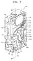
- FIG. 2is a perspective view of the optical module according to an embodiment of the present invention.
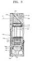
- FIG. 3is a cross-sectional view taken along line III-III of FIG. 2 ;
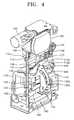
- FIG. 4is a perspective view of the optical module according to an embodiment of the present invention in which a frame is removed;
- FIG. 5is an exploded perspective view of the optical module according to an embodiment of the present invention.
- FIG. 6is a front view showing a zoom motor, a gear train, and a plane cam member of the optical module according to an embodiment of the present invention
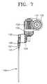
- FIG. 7is a side view of FIG. 6 ;
- FIG. 8is a view showing that the optical module according to an embodiment of the present invention is in a wide mode
- FIG. 9is a view showing that the optical module according to an embodiment of the present invention is in a middle mode
- FIG. 10is a view showing that the optical module according to an embodiment of the present invention is in a tele mode
- FIG. 11is a front view of a zoom motor, a gear train, and a plane cam member of an optical module according to another embodiment of the present invention.
- FIG. 12is a side view of FIG. 11 .
- FIG. 1is a perspective view showing an optical module according to an embodiment of the present invention is arranged in a photographing apparatus.
- a photographing apparatus 10according to an embodiment of the present invention has a slim structure in which the width of a front surface S 1 is larger than the width of a side surface S 2 .
- a shutter switch 11is provided on the upper surface of the photographing device 10 .
- the photographing device 10has a flash 12 and an auxiliary light unit 13 on the front surface S 1 and an LCD display unit 14 on the rear surface.
- An optical module 100is provided at one side of the photographing apparatus 10 .
- An objectis arranged in front of the photographing apparatus 10 .
- the optical module 100photographs the object and inputs an image light of the object to an internal imaging device.
- the optical module 100 for a photographing deviceincludes a first lens group member 110 , a second lens group member 120 , a zoom motor 130 , a plane cam (2D cam) cam member 140 , a fixed lens group member 150 , a reflection member 160 , and a frame 196 .
- a zoom operationis embodied by the first lens group member 110 , the second lens group member 120 , the zoom motor 130 , and the plane cam member 140 .
- a first optical axis direction L 1is a direction facing an object and a second optical axis direction L 2 is a direction perpendicular to the first optical axis and penetrating a first lens group 111 and a second lens group 121 .
- the first lens group member 110includes the first lens group 111 and a first edge unit 112 .
- the first lens group 111includes at least one lens and is arranged along the second optical axis direction L 2 .
- the first edge unit 112encompasses and supports the first lens group 111 .
- An extended unit 112 ais provided at a side of the first edge unit 112 .
- a first guide protrusion 112 bis formed at an end portion of the extended unit 112 a .
- the first edge unit 112includes the extended unit 112 a and the first guide protrusion 112 b is formed on the extended unit 112 a
- the first edge unit 112may not include the extended unit 112 a and the first guide protrusion 112 b may be formed directly on the first edge unit 112 .
- a first guide groove 113 a and a first guide hole 113 bare formed in the first edge unit 112 .
- the first guide groove 113 a and the first guide hole 113 bare formed in the first edge unit 112
- the first guide groovescan be formed in the first edge unit 112 .
- the first guide holesonly can be formed in the first edge unit 112 .
- first guide groove 113 a or the first guide hole 113 bis inserted around a guide rod 195 to perform a function of guiding the first edge unit 112 along the second optical axis direction L 2 , either the first guide groove 113 a or the first guide hole 113 b can be compatibly arranged.
- the second lens group member 120is arranged separated from the first lens group member 110 along the second optical axis direction L 2 .
- the second lens group member 120includes the second lens group 121 and a second edge unit 122 .
- the second lens group 121includes at least one lens and is arranged along the second optical axis direction L 2 .
- the second edge unit 122encompasses and supports the second lens group 121 .
- An extended unit 122 ais provided at a side of the second edge unit 122 .
- a second guide protrusion 122 bis formed at an end portion of the extended unit 122 a .
- the second edge unit 122includes the extended unit 122 a and the second guide protrusion 122 b is formed on the extended unit 122 a
- the second edge unit 122may not include the extended unit 122 a and the second guide protrusion 122 b may be formed directly on the second edge unit 122 .
- a second guide groove 123 a and a second guide hole 123 bare formed in the second edge unit 122 .
- the second guide groove 123 a and the second guide hole 123 bare formed in the second edge unit 122
- the second guide groovescan be formed in the second edge unit 122 .
- the second guide holescan be formed in the second edge unit 122 .
- either the second guide groove 123 a or the second guide hole 123 bcan be compatibly arranged.
- the zoom motor 130is arranged in near of the reflection member 160 and the zoom motor 130 provides power to change a distance between the first lens group member 110 and the second lens group member 120 .
- the zoom motor 130is arranged in the rear of the reflection member 160 with respect to the first optical axis direction L 1 and a shaft 130 a of the zoom motor 130 is arranged perpendicular to the first and second optical axis directions L 1 and L 2 .
- the size of the diameter of the zoom motor 130is less than the height of the fixed lens group member 150 that is described later.
- the size and arrangement structure of the zoom motor 130can minimize the volume of the optical module 100 , which enables the efficient use of a space.
- the plane cam member 140has a plane plate structure.
- a gear unit 141is formed at a side of an edge portion of the plane cam member 140 and a first cam slot 142 and a second cam slot 143 are formed at the center portion thereof.
- a rotation center hole 144is formed around the second cam slot 143 .
- the gear unit 141has a predetermined pitch circle and has an involute teeth shape.
- the length of the gear unit 141is appropriately determined by a designer according to the rotation available angle of the plane cam member 140 .
- the gear unit 141 in this examplehas a predetermined pitch circle and the involute teeth shape, but there shape of the gear unit 141 or the shape of teeth forming the gear unit 141 can have any suitable shape.
- the gear unit 141is shaped to receive power from the zoom motor 130 to perform the rotation motion of the plane cam member 140 .
- the gear unitmay have a rack gear shape or a cycloid teeth shape.
- the first cam slot 142 in this examplehas a U shape so that the first guide protrusion 112 b is inserted to slide therein.
- the second cam slot 143has an arc shape having a predetermined curvature so that the second guide protrusion 122 b is inserted to slide therein, but it is also sufficient that the first and second cam slots 142 and 143 are formed to perform a necessary zoom operation as the distance between the first lens group member 110 and the second lens group member 120 appropriately changes according to the rotation of the plane cam member 140 .
- There is no specific shape of the first and second cam slots 142 and 143That is, a designer determines the amount of change in distance between the first and second lens group members 110 and 120 that is needed for the zoom operation and the curvature and shape of the first and second cam slots 142 and 143 according to the amount of change in distance.
- the rotation center hole 144is a position of the center of the rotation of the plane cam member 140 . That is, a hinge coupling is made as a fixing pin 196 a of the frame 196 is inserted in the rotation center hole 144 , so that the plane cam member 140 rotates around the position of the rotation center hole 144 .
- the fixed lens group member 150is arranged above the optical module 100 according to the present embodiment, that is, above the first lens group member 110 , along the first optical axis direction L 1 .
- the reflection member 160 to reflect the photographed image light to proceed toward the first lens group 111 arranged in the second optical axis direction L 2is arranged in the rear of the fixed lens group member 150 .
- the reflection member 160is formed of a prism or reflection mirror and reflects the incident image light by changing the angle of the incident image light.
- a shutter and iris assembly 170performing functions of a shutter and a light exposure amount adjustment is installed on the upper surface of the second lens group member 120 to be capable of moving with the second lens group member 120 .
- a third lens group member 180is arranged along the second optical axis direction L 2 under the optical module 100 according to the present embodiment, that is, under the second lens group member 120 , and an imaging device member 190 is arranged under the third lens group member 180 .
- the third lens group member 180includes a third lens group 181 , a third edge unit 182 , and a third lens group drive motor 183 and performs a function of assisting the zoom operation by processing the image light. Also, the third lens group member 180 performs an auto focus function and a function of a focusing lens group member.
- the third lens group member 180assists the zoom operation while transferred by a drive device separate from that for the first and second lens group members 110 and 120 .
- a drive deviceseparate from that for the first and second lens group members 110 and 120 .
- An imaging deviceis installed on the imaging device member 190 .
- a CCD (charge coupled device) or CMOS (complementary metal oxide semiconductor)can be used as the imaging device and other image sensor can be used therefor.
- the guide rod 195is installed on the frame 196 parallel to the second optical axis direction L 2 and in the present embodiment two guide rods 195 are installed symmetrically to the left and right.
- the guide rod 195is inserted in the first guide groove 113 a , the first guide hole 113 b , the second guide groove 123 a , and the second guide hole 123 b so as to guide the first and second lens group members 110 and 120 to move along the second optical axis direction L 2 .
- the number of the guide rod 195is described to be two there is no limit to the number of the guide rods 195 that can be used.
- the number of the guide rod 195 according to the present inventionmay be one, three, or four, or any other suitable number.
- FIG. 6is a front view showing a zoom motor, a gear train, and a plane cam member of the optical module according to an embodiment of the present invention.
- FIG. 7is a side view of FIG. 6 .
- a worm 131is inserted around the shaft 130 a of the zoom motor 130 .
- a worm wheel 132is arranged to be engaged with the worm 131 perpendicular to the direction of the shaft 130 a of the zoom motor 130 .
- a first bevel gear 133is installed on a shaft of the worm wheel 132 .
- a second bevel gear 134is engaged with the first bevel gear 133 .
- a first spur gear 135is installed on a shaft of the second bevel gear 134 .
- a second spur gear 136is engaged with the first spur gear 135 .
- a third spur gear 137is engaged with the second spur gear 136 .
- the gear unit 141 of the plane cam member 140is engaged with the third spur gear 137 so that power is transmitted from the shaft 130 a of the zoom motor 130 to the gear unit 141 of the plane cam member 140 .
- the plane cam member 140is rotated around the rotation center hole 144 and the fixing pin 196 a as indicated by an arrow shown in FIG. 6 .
- the first guide protrusion 112 b and the second guide protrusion 122 bslide along the first and second cam slots 142 and 143 so that the distance between the first and second lens group members 110 and 120 changes, thus performing the zoom operation.
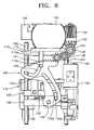
- FIG. 8is a view showing that the optical module according to an embodiment of the present invention is in a wide mode.
- FIG. 9is a view showing that the optical module according to an embodiment of the present invention is in a middle mode.
- FIG. 10is a view showing that the optical module according to an embodiment of the present invention is in a tele mode.
- the initialization operationmeans that, when the zoom motor 130 is driven to rotate the third spur gear 137 clockwise, the gear unit 141 engaged with the third spur gear 137 counterclockwise so that the plane cam member 140 rotates counterclockwise.
- the initialization operationends when the distance between the first and second lens group members 110 and 120 becomes maximum as the first guide protrusion 112 b is located at the end portion in the upper right side of the first cam slot 142 and the second guide protrusion 122 b is moved to the lower end portion of the second cam slot 143 .
- the positional state of the optical module 100is referred to a wide-angle extremity which is used when an object is photographed at a wide angle.
- a zoom switch(not shown) is operated to drive the zoom motor 130 to rotate the third spur gear 137 counterclockwise. Then, the gear unit 141 engaged with the third spur gear 137 is moved clockwise so that the plane cam member 140 rotates clockwise.
- the first guide protrusion 112 bis moved to the lower left side of the first cam slot 142 and passes through a curve point at the lowest portion of the first cam slot 142 . Then, as shown in FIG. 10 , the first guide protrusion 112 b is moved to the upper left side of the first cam slot 142 to arrive at the upper left end thereof. In the meantime, the second guide protrusion 122 b ascends along the second cam slot 143 to arrive at the upper end portion of the second cam slot 143 . Consequently, as the first and second guide protrusions 112 b and 122 b are moved as described above, the distance between the first and second lens group members 110 and 120 becomes minimum as shown in FIG. 10 . The positional state of the optical module 100 in this state is referred to as a telephoto extremity.
- the design, manufacturing, and assemblyare simplified and space can be efficiently used.
- a slim photographing devicecan be manufactured.
- FIG. 11is a front view of a zoom motor, a gear train, and a plane cam member of an optical module according to another embodiment of the present invention.
- FIG. 12is a side view of FIG. 11 .
- a worm 231is inserted around a shaft 230 a of a zoom motor 230 .
- a worm wheel 232is arranged to be engaged with the worm 231 perpendicular to the direction of the shaft 230 a of the zoom motor 230 .
- a first bevel gear 233is installed on a shaft of the worm wheel 232 .
- a second bevel gear 234is engaged with the first bevel gear 233 .
- a first spur gear 235is installed on a shaft of the second bevel gear 234 .
- a second spur gear 236is engaged with the first spur gear 235 .
- a third spur gear 237is engaged with the second spur gear 236 .
- a gear unit 241 of a plane cam member 240is engaged with the third spur gear 237 so that power is transmitted from the shaft 230 a of the zoom motor 230 to the gear unit 241 of the plane cam member 240 .
- the gear unit 241is embodied by a rack gear.
- a cam guide protrusion 244is formed on the plane cam member 240 , inserted in a horizontal guide slot (not shown) formed in a frame (not shown) where the optical module is installed, and perform a function of guiding the motion of the plane cam member 240 in the horizontal direction. Since the other structure, operation, and effect of the optical module according to this present embodiment are substantially the same as those of the optical module according to the above-described embodiments, the descriptions thereon will be omitted herein.
Landscapes
- Physics & Mathematics (AREA)
- General Physics & Mathematics (AREA)
- Engineering & Computer Science (AREA)
- General Engineering & Computer Science (AREA)
- Optics & Photonics (AREA)
- Lens Barrels (AREA)
Abstract
Description
Claims (22)
Applications Claiming Priority (2)
| Application Number | Priority Date | Filing Date | Title |
|---|---|---|---|
| KR1020060084846AKR100900486B1 (en) | 2006-09-04 | 2006-09-04 | Optical module for imaging device and imaging device having same |
| KR10-2006-0084846 | 2006-09-04 |
Publications (2)
| Publication Number | Publication Date |
|---|---|
| US20080056698A1 US20080056698A1 (en) | 2008-03-06 |
| US8019212B2true US8019212B2 (en) | 2011-09-13 |
Family
ID=39151666
Family Applications (1)
| Application Number | Title | Priority Date | Filing Date |
|---|---|---|---|
| US11/820,898Expired - Fee RelatedUS8019212B2 (en) | 2006-09-04 | 2007-06-21 | Optical module for a photographing apparatus and photographing apparatus having the same |
Country Status (3)
| Country | Link |
|---|---|
| US (1) | US8019212B2 (en) |
| KR (1) | KR100900486B1 (en) |
| CN (1) | CN101140351B (en) |
Families Citing this family (36)
| Publication number | Priority date | Publication date | Assignee | Title |
|---|---|---|---|---|
| JP5280677B2 (en)* | 2007-12-28 | 2013-09-04 | パナソニック株式会社 | Lens barrel |
| WO2009084192A1 (en)* | 2007-12-28 | 2009-07-09 | Panasonic Corporation | Lens barrel and lens support structure |
| JP5432449B2 (en)* | 2007-12-28 | 2014-03-05 | パナソニック株式会社 | Lens barrel and optical element driving apparatus |
| KR101634516B1 (en) | 2013-06-13 | 2016-06-28 | 코어포토닉스 리미티드 | Dual aperture zoom digital camera |
| US9857568B2 (en) | 2013-07-04 | 2018-01-02 | Corephotonics Ltd. | Miniature telephoto lens assembly |
| JP2016523389A (en) | 2013-07-04 | 2016-08-08 | コアフォトニクス リミテッド | Compact telephoto lens assembly |
| US9392188B2 (en) | 2014-08-10 | 2016-07-12 | Corephotonics Ltd. | Zoom dual-aperture camera with folded lens |
| JP6481242B2 (en)* | 2014-10-29 | 2019-03-13 | 新シコー科技株式会社 | LENS DRIVE DEVICE, CAMERA DEVICE, AND ELECTRONIC DEVICE |
| CN112433331B (en) | 2015-01-03 | 2022-07-08 | 核心光电有限公司 | Miniature telephoto lens module and camera using the same |
| JP2018124396A (en)* | 2017-01-31 | 2018-08-09 | 日本電産コパル株式会社 | Lens drive device |
| KR102212611B1 (en) | 2017-02-23 | 2021-02-05 | 코어포토닉스 리미티드 | Folded camera lens designs |
| JP2020509420A (en) | 2017-07-07 | 2020-03-26 | コアフォトニクス リミテッド | Bend camera prism design to prevent stray light |
| IL314519A (en) | 2017-07-23 | 2024-09-01 | Corephotonics Ltd | Compact folded lenses with a large entry key |
| EP3759538A4 (en) | 2018-03-02 | 2021-05-05 | Corephotonics Ltd. | DESIGN OF SPACING ELEMENTS TO REDUCE PARASITIC LIGHT |
| KR20250048118A (en) | 2018-05-14 | 2025-04-07 | 코어포토닉스 리미티드 | Folded camera lens designs |
| US11336830B2 (en) | 2019-01-03 | 2022-05-17 | Corephotonics Ltd. | Multi-aperture cameras with at least one two state zoom camera |
| KR20250051137A (en) | 2019-02-25 | 2025-04-16 | 코어포토닉스 리미티드 | Multi-aperture cameras with at least one two state zoom camera |
| WO2021033047A1 (en) | 2019-08-21 | 2021-02-25 | Corephotonics Ltd. | Low total track length for large sensor format |
| US12072609B2 (en) | 2019-09-24 | 2024-08-27 | Corephotonics Ltd. | Slim pop-out cameras and lenses for such cameras |
| US11656538B2 (en) | 2019-11-25 | 2023-05-23 | Corephotonics Ltd. | Folded zoom camera module with adaptive aperture |
| US11689708B2 (en) | 2020-01-08 | 2023-06-27 | Corephotonics Ltd. | Multi-aperture zoom digital cameras and methods of using same |
| US11770609B2 (en) | 2020-05-30 | 2023-09-26 | Corephotonics Ltd. | Systems and methods for obtaining a super macro image |
| KR102765964B1 (en) | 2020-07-22 | 2025-02-07 | 코어포토닉스 리미티드 | Folded camera lens design |
| CN119414645A (en) | 2020-07-31 | 2025-02-11 | 核心光电有限公司 | camera |
| EP4127788A4 (en) | 2020-09-18 | 2024-06-19 | Corephotonics Ltd. | Pop-out zoom camera |
| US12271105B2 (en) | 2020-11-05 | 2025-04-08 | Corephotonics Ltd. | Scanning Tele camera based on two prism field of view scanning |
| KR20250008791A (en) | 2020-12-01 | 2025-01-15 | 코어포토닉스 리미티드 | Folded camera with continuously adaptive zoom factor |
| CN117425062A (en) | 2021-01-25 | 2024-01-19 | 核心光电有限公司 | Lens system for compact digital camera |
| WO2022200965A1 (en) | 2021-03-22 | 2022-09-29 | Corephotonics Ltd. | Folded cameras with continuously adaptive zoom factor |
| KR20240012438A (en) | 2021-06-23 | 2024-01-29 | 코어포토닉스 리미티드 | Compact folded tele camera |
| KR102685591B1 (en) | 2021-09-23 | 2024-07-15 | 코어포토닉스 리미티드 | Large aperture continuous zoom folded telecamera |
| CN119414565A (en) | 2021-11-02 | 2025-02-11 | 核心光电有限公司 | Camera module and mobile device |
| CN120315167A (en) | 2021-12-14 | 2025-07-15 | 核心光电有限公司 | Large aperture compact scan telephoto camera |
| CN114120757B (en)* | 2021-12-22 | 2023-04-18 | 滨州学院 | Three-dimensional fine arts teaching display device of shadow transform |
| US12348870B2 (en) | 2022-04-09 | 2025-07-01 | Corephotonics Ltd. | Spin-out 360-degree camera for smartphone |
| US12368960B2 (en) | 2022-08-05 | 2025-07-22 | Corephotonics Ltd. | Systems and methods for zoom digital camera with automatic adjustable zoom field of view |
Citations (17)
| Publication number | Priority date | Publication date | Assignee | Title |
|---|---|---|---|---|
| US4958178A (en)* | 1987-11-16 | 1990-09-18 | Fuji Photo Film Co., Ltd. | Collapsible mounting type camera with zoom lens |
| US5339126A (en)* | 1992-06-17 | 1994-08-16 | Konica Corporation | Zoom lens barrel |
| US5636039A (en)* | 1991-09-05 | 1997-06-03 | Canon Kabushiki Kaisha | TV conference system and terminal equipment for use in the same |
| US5765047A (en)* | 1993-12-13 | 1998-06-09 | Nikon Corporation | Lens shutter camera having a zoom viewfinder mechanism and an adjustable strobe light generating unit |
| US5790908A (en)* | 1995-02-06 | 1998-08-04 | Asahi Kogaku Kogyo Kabushiki Kaisha | Diopter control apparatus in a zoom camera |
| US5848302A (en)* | 1991-03-14 | 1998-12-08 | Nikon Corporation | Multi-motor camera for normal and trimming photography having variable focal length photographing lens and finder and variable illuminating angle flash device |
| US5937215A (en)* | 1996-11-29 | 1999-08-10 | Asahi Kogaku Kogyo Kabushiki Kaisha | Camera having a zoom lens |
| US6434331B1 (en)* | 1999-02-19 | 2002-08-13 | Olympus Optical Co., Ltd. | Lens barrel |
| US6618212B2 (en)* | 2000-12-19 | 2003-09-09 | Minolta Co., Ltd. | Lens driving apparatus and photographic apparatus |
| US6710936B2 (en)* | 2002-05-17 | 2004-03-23 | Samsung Electro-Mechanics Co., Ltd. | Image sensor module with zooming function |
| US20050036056A1 (en)* | 2003-06-17 | 2005-02-17 | Masaru Ikemachi | Encoder, lens-implement and digital camera |
| US20050052536A1 (en)* | 1999-09-02 | 2005-03-10 | Olympus Optical Co., Ltd | Electronic imaging device |
| US20050185947A1 (en)* | 2004-01-13 | 2005-08-25 | Katsuyuki Honda | Drive apparatus, lens unit, and camera |
| US20060158546A1 (en)* | 2005-01-20 | 2006-07-20 | Pentax Corporation | Image surface illuminance varying apparatus, exposure correcting apparatus, and exposure correcting method |
| US20060285841A1 (en)* | 2005-06-17 | 2006-12-21 | Konica Minolta Photo Imaging, Inc. | Variable-magnification optical system and image-taking apparatus therewith |
| US7307797B2 (en)* | 2006-02-13 | 2007-12-11 | Matsushita Electric Industrial Co., Ltd. | Zoom lens system, lens barrel, imaging device and camera |
| US7440023B2 (en)* | 2004-08-31 | 2008-10-21 | Canon Kabushiki Kiasha | Image pickup apparatus equipped with light emitting device and control method thereof |
Family Cites Families (9)
| Publication number | Priority date | Publication date | Assignee | Title |
|---|---|---|---|---|
| JPH01243039A (en)* | 1988-03-24 | 1989-09-27 | Canon Inc | Zoom camera |
| FR2658926A1 (en)* | 1990-02-14 | 1991-08-30 | Asahi Optical Co Ltd | Photographic apparatus with a zoom lens including a macro view taking function |
| DE4204468C2 (en)* | 1991-02-19 | 1995-09-21 | Asahi Optical Co Ltd | Camera with parallax and diopter correction |
| JPH11258678A (en)* | 1998-03-11 | 1999-09-24 | Olympus Optical Co Ltd | Lens barrel |
| JP2002258132A (en)* | 2001-03-05 | 2002-09-11 | Olympus Optical Co Ltd | Camera |
| JP2003007598A (en)* | 2001-06-25 | 2003-01-10 | Mitsubishi Electric Corp | Focus monitor method, focus monitor device, and semiconductor device manufacturing method |
| JP2004029665A (en) | 2002-06-28 | 2004-01-29 | Fuji Photo Optical Co Ltd | Camera |
| JP2005321545A (en)* | 2004-05-07 | 2005-11-17 | Sony Corp | Imaging apparatus |
| CN2748937Y (en)* | 2004-08-31 | 2005-12-28 | 陈锡阳 | A portable information terminal and shooting device capable of optical zooming and rotating shooting |
- 2006
- 2006-09-04KRKR1020060084846Apatent/KR100900486B1/ennot_activeExpired - Fee Related
- 2007
- 2007-06-21USUS11/820,898patent/US8019212B2/ennot_activeExpired - Fee Related
- 2007-07-27CNCN2007101367658Apatent/CN101140351B/ennot_activeExpired - Fee Related
Patent Citations (20)
| Publication number | Priority date | Publication date | Assignee | Title |
|---|---|---|---|---|
| US4958178A (en)* | 1987-11-16 | 1990-09-18 | Fuji Photo Film Co., Ltd. | Collapsible mounting type camera with zoom lens |
| US5848302A (en)* | 1991-03-14 | 1998-12-08 | Nikon Corporation | Multi-motor camera for normal and trimming photography having variable focal length photographing lens and finder and variable illuminating angle flash device |
| US5636039A (en)* | 1991-09-05 | 1997-06-03 | Canon Kabushiki Kaisha | TV conference system and terminal equipment for use in the same |
| US5339126A (en)* | 1992-06-17 | 1994-08-16 | Konica Corporation | Zoom lens barrel |
| US5765047A (en)* | 1993-12-13 | 1998-06-09 | Nikon Corporation | Lens shutter camera having a zoom viewfinder mechanism and an adjustable strobe light generating unit |
| US5790908A (en)* | 1995-02-06 | 1998-08-04 | Asahi Kogaku Kogyo Kabushiki Kaisha | Diopter control apparatus in a zoom camera |
| US5937215A (en)* | 1996-11-29 | 1999-08-10 | Asahi Kogaku Kogyo Kabushiki Kaisha | Camera having a zoom lens |
| US6434331B1 (en)* | 1999-02-19 | 2002-08-13 | Olympus Optical Co., Ltd. | Lens barrel |
| US7123423B2 (en)* | 1999-09-02 | 2006-10-17 | Olympus Optical Co., Ltd. | Electronic imaging device |
| US20050052536A1 (en)* | 1999-09-02 | 2005-03-10 | Olympus Optical Co., Ltd | Electronic imaging device |
| US7248419B2 (en)* | 1999-09-02 | 2007-07-24 | Olympus Optical Co., Ltd. | Electronic imaging device |
| US6618212B2 (en)* | 2000-12-19 | 2003-09-09 | Minolta Co., Ltd. | Lens driving apparatus and photographic apparatus |
| US6710936B2 (en)* | 2002-05-17 | 2004-03-23 | Samsung Electro-Mechanics Co., Ltd. | Image sensor module with zooming function |
| US20050036056A1 (en)* | 2003-06-17 | 2005-02-17 | Masaru Ikemachi | Encoder, lens-implement and digital camera |
| US7567284B2 (en)* | 2003-06-17 | 2009-07-28 | Olympus Corporation | Encoder, lens-implement and digital camera |
| US20050185947A1 (en)* | 2004-01-13 | 2005-08-25 | Katsuyuki Honda | Drive apparatus, lens unit, and camera |
| US7440023B2 (en)* | 2004-08-31 | 2008-10-21 | Canon Kabushiki Kiasha | Image pickup apparatus equipped with light emitting device and control method thereof |
| US20060158546A1 (en)* | 2005-01-20 | 2006-07-20 | Pentax Corporation | Image surface illuminance varying apparatus, exposure correcting apparatus, and exposure correcting method |
| US20060285841A1 (en)* | 2005-06-17 | 2006-12-21 | Konica Minolta Photo Imaging, Inc. | Variable-magnification optical system and image-taking apparatus therewith |
| US7307797B2 (en)* | 2006-02-13 | 2007-12-11 | Matsushita Electric Industrial Co., Ltd. | Zoom lens system, lens barrel, imaging device and camera |
Also Published As
| Publication number | Publication date |
|---|---|
| CN101140351A (en) | 2008-03-12 |
| CN101140351B (en) | 2011-07-13 |
| KR20080021434A (en) | 2008-03-07 |
| KR100900486B1 (en) | 2009-06-03 |
| US20080056698A1 (en) | 2008-03-06 |
Similar Documents
| Publication | Publication Date | Title |
|---|---|---|
| US8019212B2 (en) | Optical module for a photographing apparatus and photographing apparatus having the same | |
| JP6415102B2 (en) | Lens barrel and optical apparatus having the same | |
| US8004774B2 (en) | Lens apparatus and image-pickup apparatus | |
| US7742246B2 (en) | Lens barrel and camera with lens barrel | |
| JP3582022B2 (en) | Zoom lens barrel | |
| US6546200B2 (en) | Lens interlock mechanism and lens interlock method, camera and portable terminal having lens interlock mechanism | |
| US7532418B2 (en) | Lens barrel and image pickup apparatus | |
| WO2004099870A1 (en) | Camera | |
| US7787192B2 (en) | Lens unit and photographing apparatus | |
| JP2002107598A (en) | Retractable lens barrel and optical equipment using the same | |
| JP2009192581A (en) | Lens-barrel and imaging apparatus | |
| JP2009181102A (en) | Lens barrel and imaging device | |
| JP2003344747A (en) | camera | |
| JP2002156572A (en) | Lens interlocking mechanism and lens unit | |
| US6798582B2 (en) | Reduction gear mechanism | |
| JP4532673B2 (en) | Optical apparatus and photographing apparatus | |
| JP2007121494A (en) | Lens barrel and imaging apparatus | |
| JP2006003851A (en) | Bifocal length switching lens barrel | |
| JP2005274717A (en) | Zoom camera | |
| JP2003005010A (en) | Lens driving device, lens barrel, and imaging device | |
| JP2007163841A (en) | Lens barrel, imaging apparatus and lens position adjusting method | |
| JP2008102420A (en) | Focal length variable device and camera | |
| JPH1144835A (en) | Camera lens drive mechanism | |
| JPH05173223A (en) | Camera with built-in zoom lens with zoom finder | |
| JP2007086139A (en) | Lens drive device, lens barrel, and imaging apparatus |
Legal Events
| Date | Code | Title | Description |
|---|---|---|---|
| AS | Assignment | Owner name:SAMSUNG TECHWIN CO., LTD., KOREA, REPUBLIC OF Free format text:ASSIGNMENT OF ASSIGNORS INTEREST;ASSIGNORS:LEE, SANG-GEOL;JEON, JONG;REEL/FRAME:019565/0009 Effective date:20070618 | |
| FEPP | Fee payment procedure | Free format text:PAYOR NUMBER ASSIGNED (ORIGINAL EVENT CODE: ASPN); ENTITY STATUS OF PATENT OWNER: LARGE ENTITY | |
| ZAAA | Notice of allowance and fees due | Free format text:ORIGINAL CODE: NOA | |
| ZAAB | Notice of allowance mailed | Free format text:ORIGINAL CODE: MN/=. | |
| STCF | Information on status: patent grant | Free format text:PATENTED CASE | |
| FPAY | Fee payment | Year of fee payment:4 | |
| AS | Assignment | Owner name:HANWHA TECHWIN CO., LTD., KOREA, DEMOCRATIC PEOPLE Free format text:CHANGE OF NAME;ASSIGNOR:SAMSUNG TECHWIN CO., LTD.;REEL/FRAME:036714/0757 Effective date:20150629 | |
| AS | Assignment | Owner name:HANWHA TECHWIN CO., LTD., KOREA, REPUBLIC OF Free format text:CORRECTIVE ASSIGNMENT TO CORRECT THE RECEIVING PARTY ADDRESS PREVIOUSLY RECORDED AT REEL: 036714 FRAME: 0757. ASSIGNOR(S) HEREBY CONFIRMS THE CHANGE OF NAME;ASSIGNOR:SAMSUNG TECHWIN CO., LTD.;REEL/FRAME:037072/0008 Effective date:20150629 | |
| AS | Assignment | Owner name:INTELLECTUAL DISCOVERY CO., LTD., KOREA, REPUBLIC Free format text:ASSIGNMENT OF ASSIGNORS INTEREST;ASSIGNOR:HANWHA TECHWIN CO., LTD.;REEL/FRAME:039193/0105 Effective date:20160711 | |
| AS | Assignment | Owner name:COMPACT LENS TECHNOLOGIES LLC, TEXAS Free format text:ASSIGNMENT OF ASSIGNORS INTEREST;ASSIGNOR:INTELLECTUAL DISCOVERY CO., LTD;REEL/FRAME:043841/0206 Effective date:20171011 | |
| AS | Assignment | Owner name:HANWHA AEROSPACE CO., LTD., KOREA, REPUBLIC OF Free format text:CHANGE OF NAME;ASSIGNOR:HANWHA TECHWIN CO., LTD;REEL/FRAME:046927/0019 Effective date:20180401 | |
| MAFP | Maintenance fee payment | Free format text:PAYMENT OF MAINTENANCE FEE, 8TH YEAR, LARGE ENTITY (ORIGINAL EVENT CODE: M1552); ENTITY STATUS OF PATENT OWNER: LARGE ENTITY Year of fee payment:8 | |
| FEPP | Fee payment procedure | Free format text:MAINTENANCE FEE REMINDER MAILED (ORIGINAL EVENT CODE: REM.); ENTITY STATUS OF PATENT OWNER: LARGE ENTITY | |
| LAPS | Lapse for failure to pay maintenance fees | Free format text:PATENT EXPIRED FOR FAILURE TO PAY MAINTENANCE FEES (ORIGINAL EVENT CODE: EXP.); ENTITY STATUS OF PATENT OWNER: LARGE ENTITY | |
| STCH | Information on status: patent discontinuation | Free format text:PATENT EXPIRED DUE TO NONPAYMENT OF MAINTENANCE FEES UNDER 37 CFR 1.362 | |
| FP | Lapsed due to failure to pay maintenance fee | Effective date:20230913 |