US8019068B2 - Method of allocating power for the simultaneous downlink conveyance of information between multiple antennas and multiple destinations - Google Patents
Method of allocating power for the simultaneous downlink conveyance of information between multiple antennas and multiple destinationsDownload PDFInfo
- Publication number
- US8019068B2 US8019068B2US09/950,741US95074101AUS8019068B2US 8019068 B2US8019068 B2US 8019068B2US 95074101 AUS95074101 AUS 95074101AUS 8019068 B2US8019068 B2US 8019068B2
- Authority
- US
- United States
- Prior art keywords
- channel conditions
- subscribers
- antennas
- subscriber
- sets
- Prior art date
- Legal status (The legal status is an assumption and is not a legal conclusion. Google has not performed a legal analysis and makes no representation as to the accuracy of the status listed.)
- Expired - Fee Related, expires
Links
- 238000000034methodMethods0.000titleclaimsabstractdescription29
- 238000004891communicationMethods0.000claimsabstractdescription68
- 238000004364calculation methodMethods0.000claimsabstractdescription5
- 230000011664signalingEffects0.000claimsdescription28
- 230000005540biological transmissionEffects0.000claimsdescription6
- 238000005259measurementMethods0.000claimsdescription2
- 229920001690polydopaminePolymers0.000claims1
- 230000001413cellular effectEffects0.000description2
- 238000010586diagramMethods0.000description2
- 238000012545processingMethods0.000description2
- 230000002411adverseEffects0.000description1
- 238000013461designMethods0.000description1
- 238000011156evaluationMethods0.000description1
- 239000013307optical fiberSubstances0.000description1
- 230000000737periodic effectEffects0.000description1
- 230000005855radiationEffects0.000description1
- 238000012546transferMethods0.000description1
- 238000013519translationMethods0.000description1
Images


Classifications
- H—ELECTRICITY
- H04—ELECTRIC COMMUNICATION TECHNIQUE
- H04B—TRANSMISSION
- H04B7/00—Radio transmission systems, i.e. using radiation field
- H04B7/24—Radio transmission systems, i.e. using radiation field for communication between two or more posts
- H04B7/26—Radio transmission systems, i.e. using radiation field for communication between two or more posts at least one of which is mobile
- H—ELECTRICITY
- H04—ELECTRIC COMMUNICATION TECHNIQUE
- H04W—WIRELESS COMMUNICATION NETWORKS
- H04W72/00—Local resource management
- H04W72/50—Allocation or scheduling criteria for wireless resources
- H04W72/54—Allocation or scheduling criteria for wireless resources based on quality criteria
- H—ELECTRICITY
- H04—ELECTRIC COMMUNICATION TECHNIQUE
- H04W—WIRELESS COMMUNICATION NETWORKS
- H04W52/00—Power management, e.g. Transmission Power Control [TPC] or power classes
- H04W52/04—Transmission power control [TPC]
- H04W52/38—TPC being performed in particular situations
- H04W52/50—TPC being performed in particular situations at the moment of starting communication in a multiple access environment
- H—ELECTRICITY
- H04—ELECTRIC COMMUNICATION TECHNIQUE
- H04W—WIRELESS COMMUNICATION NETWORKS
- H04W52/00—Power management, e.g. Transmission Power Control [TPC] or power classes
- H04W52/04—Transmission power control [TPC]
- H04W52/30—Transmission power control [TPC] using constraints in the total amount of available transmission power
- H04W52/34—TPC management, i.e. sharing limited amount of power among users or channels or data types, e.g. cell loading
- H—ELECTRICITY
- H04—ELECTRIC COMMUNICATION TECHNIQUE
- H04W—WIRELESS COMMUNICATION NETWORKS
- H04W52/00—Power management, e.g. Transmission Power Control [TPC] or power classes
- H04W52/04—Transmission power control [TPC]
- H04W52/38—TPC being performed in particular situations
- H04W52/42—TPC being performed in particular situations in systems with time, space, frequency or polarisation diversity
- H—ELECTRICITY
- H04—ELECTRIC COMMUNICATION TECHNIQUE
- H04W—WIRELESS COMMUNICATION NETWORKS
- H04W72/00—Local resource management
- H04W72/12—Wireless traffic scheduling
- H04W72/121—Wireless traffic scheduling for groups of terminals or users
- H—ELECTRICITY
- H04—ELECTRIC COMMUNICATION TECHNIQUE
- H04W—WIRELESS COMMUNICATION NETWORKS
- H04W72/00—Local resource management
- H04W72/12—Wireless traffic scheduling
- H04W72/1263—Mapping of traffic onto schedule, e.g. scheduled allocation or multiplexing of flows
- H04W72/1273—Mapping of traffic onto schedule, e.g. scheduled allocation or multiplexing of flows of downlink data flows
Definitions
- the present inventionrelates to communication systems and more particularly to wireless communication systems.
- wireless communication systemare designed to meet the varying demands of their subscribers.
- Service providerswhich are entities that own, operate and properly maintain the communication system, are constantly seeking ways to improve the overall performance of a communication system without incurring substantial cost increases in the operation of such communication systems.
- service providershave to provide communication systems that allow subscribers to convey (i.e., transmit and/or receive) relatively larger amounts of information per unit time.
- the amount of information conveyed per unit timeis the information rate.
- the total amount of information that can be conveyed over a systemis usually referred to as a system's capacity.
- system throughputThe amount of information that is successfully conveyed (i.e., information transmitted and received without errors) over a communication system is usually referred to as system throughput.
- Subscribers of a communication system with a certain system capacityare limited in the amount of information they can convey at any instant of time.
- the subscriber throughput and/or capacitywill not remain fixed. Therefore, there may be times when a subscriber desires to convey information at a certain information rate with a certain throughput, but will not be able to do so because of adverse channel conditions.
- the communication systemmay not be able to accommodate a subscriber desiring relatively higher information rates.
- subscribersuse equipment (e.g., cell phones or mobiles) that have multiple antennas instead of only one antenna.
- additional antennas in a subscriber's equipmentgives the subscriber the ability to convey information at relatively higher rates.
- the increased capacity of the subscriber's equipment through the use of additional antennaswill still be limited by the system's capacity at any instant of time.
- a subscriber equipment having multiple antennasmay have the capability and desire to convey information at a certain rate, but will be limited to a lesser rate by the system at a particular instant of time.
- System capacity and system throughputare two examples of system requirements that service providers want to manipulate so as to operate their communication systems in an efficient manner.
- Other examples of system requirementsare the power allocation to the communication system and system delay experienced by the subscribers of the communication system.
- the power allocationrefers to the amount of power available and the proportional amount of power allocated to each communication channel being used by one or more subscribers.
- System delayrefers to the amount of latency experienced by subscriber signals as a result of such signals being processed by system equipment owned, operated and maintained by the service provider.
- System providerswant to provide relatively large system capacity and throughput to their subscribers with the amount of total power available to the system while reducing system delay as much as possible. Many times these system requirements conflict with each other and make it difficult to achieve efficient operation of the communication system. Service providers often resort to buying additional equipment to satisfy one or more of the system requirements. What is therefore needed is a method and system where one or more system requirements can be achieved without the service provider incurring the cost of additional equipment.
- the present inventionprovides a method that allows a service provider to satisfy one or more system requirements by allocating the proper amount of power to communication channels being used by subscribers of a wireless communication system.
- the system equipmente.g., base station
- the system equipmentis provided with multiple antennas for transmitting and receiving simultaneously traffic signals and signaling signals to and from a multiple of subscribers.
- the method of the present inventiondetermines sets of downlink channel conditions from the received signaling information where each set of downlink channel conditions is associated with a subscriber requesting access to the communication system and/or a subscriber being provided access to the communication system. Proper power allocations associated with the sets of downlink channel conditions are calculated.
- the calculated power allocations and their associated sets of downlink channel conditionsare then applied to a scheduler.
- the schedulerselects a set of subscribers to be given access to the downlink channels that will satisfy one or more system requirements. In this manner, a service provider is able to satisfy or even surpass one or more system requirements without incurring the cost of procuring additional equipment.
- the multiple antennasneed not be co-located at a particular base station and the scheduler of the present invention can be part of the base station equipment or part of other system equipment operated, maintained and owned by the service provider of the communication system.
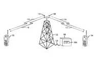
- FIG. 1shows a portion of a wireless communication system with a scheduler that is part of base station equipment and downlink channels that allow subscribers to communicate with the base station.
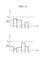
- FIG. 2shows a timing diagram of the power allocated to each of the two antennas shown in FIG. 1 .
- FIG. 3shows a flowchart depicting the method of the present invention.
- the present inventionprovides a method that allows a service provider to satisfy one or more system requirements by allocating the proper amount of power to communication channels being used by subscribers of a wireless communication system.
- the system equipmente.g., base station
- the system equipmentis provided with multiple antennas for transmitting and receiving simultaneously traffic signals and signaling signals to and from a multiple of subscribers.
- the method of the present inventiondetermines sets of downlink channel conditions from the received signaling information where each set of downlink channel conditions is associated with a subscriber requesting access to the communication system or a subscriber being provided access to the communication system (incoming call to a subscriber, for example). Proper power allocations associated with the sets of downlink channel conditions are calculated.
- the calculated power allocations and their associated sets of downlink channel conditionsare then applied to a scheduler.
- the schedulerselects a set of subscribers to be given access to the downlink channels to satisfy one or more system requirements. In this manner, a service provider is able to satisfy or even surpass one or more system requirements without incurring the cost of procuring additional equipment.
- the multiple antennasneed not be co-located at a particular base station and the scheduler of the present invention can be part of the base station equipment or part of other system equipment operated, maintained and owned by the service provider of the communication system.
- the terms ‘subscriber’ and ‘subscriber equipment’will hereinafter be used interchangeably to denote a subscriber of the communication system using typical subscriber equipment to convey information over the system. Access to the communication system is a subscriber being able to use the resources (e.g., communication channels, power allocation) of the communication system to convey information to other subscribers or to the system.
- FIG. 1there is shown a portion of a wireless communication system comprising a base station and two subscriber equipment ( 102 , 104 ) shown as cellular phones.
- the subscriber equipmentis not limited to cellular phones but can be any type of communication equipment (e.g., laptop personal computer, Personal Digital Assistant (PDA)) typically used by subscribers of communication systems.
- the base stationhas base station equipment comprising tower 122 with two antennas 108 and 110 connected to electrical and electronic equipment 106 via cable 120 .
- Cable 120can be a coaxial cable, an electrical wire cable, an optical fiber cable or any combination thereof. It should be noted that the method of the present invention is applicable to system equipment having N antennas where N is an integer equal to 2 or greater.
- the number of subscribers in simultaneous communication with the base stationis not limited to two; the method of the present invention is applicable to a plurality of subscribers being scheduled to communicate with a plurality of antennas.
- the base station depicted in FIG. 1 and the description which followsrefer to two antennas in communication with two subscribers.
- electrical and electronic equipment 106comprise typical radio equipment and signal processing equipment used to generate and process communication signals.
- Scheduler 106 Aforms part of equipment 106 and can be implemented as software, firmware, hardware or any combination thereof.
- Subscribers 102 and 104communicate with the base station over an air interface.
- the air interfacecomprises communication channels through which traffic signals and signaling information are conveyed.
- the traffic signalsare the signals being conveyed between different subscribers or between subscribers and base station equipment or other system equipment.
- System equipmentare any equipment that are part of the communication system which are owned, operated and maintained by the service provider.
- the signaling informationare information being conveyed between subscriber equipment and base station equipment. The signaling information is used to operate the communication system in accordance with a particular protocol from a standard being followed by the communication system.
- the communication channels constituting the air interfaceare uplink channels and downlink channels.
- the uplink channels(not shown) are channels through which subscriber equipment transmit information to a base station or other system equipment.
- the downlink traffic channels shown in FIG. 1are channels 112 , 114 , 116 and 118 are communication channels through which the base station (or other system equipment) transmit information to the subscriber equipment.
- There are also downlink signaling channels (not shown)which are used by the base station or other system equipment to transmit signaling information to the subscriber equipment.
- FIG. 1shows antenna 108 transmitting traffic simultaneously to subscribers 102 and 104 via downlink communication channels 118 and 114 respectively.
- antenna 110is transmitting traffic signals simultaneously to subscriber equipment 102 and 104 via downlink communication channels 116 and 112 respectively.
- FIG. 2there is shown a power allocation timing diagram for the two subscriber equipment shown in FIG. 1 .
- Power allocation to an antennarefers to the amount of power provided to radio equipment and processing equipment coupled to that particular antenna which equipment enable the transmission and reception of signals with that antenna.
- the particular amount of power allocated to each antennalasts for a certain time period.
- the time period for each antennaneed not coincide with the time period for any other antenna. However, for the sake of simplicity, the time periods shown in FIG. 2 are the same for each antenna.
- step 300information received by the base station (such as the one in FIG. 1 ) is processed by the base station.
- the base stationis provided with a multiple of antennas for simultaneously conveying information to one or a multiple of subscribers.
- the received informationis signaling information transmitted over an uplink signaling channel (not shown) in response to downlink transmissions over communication channels 112 , 114 , 116 and 118 .
- Antenna 108transmits traffic signals and signaling information to subscriber equipment 104 over downlink channel 114 .
- Antenna 108also transmits traffic and signaling information to subscriber 102 over downlink channel 118 .
- Antenna 110transmits traffic signals and signaling information to subscriber equipment 104 over downlink channel 112 and to subscriber 102 over downlink channel 116 .
- Subscriber equipment 104 and 102measure characteristics of the traffic and signaling signals from antennas 108 and 110 . It is well known that subscriber equipment (e.g., cell phones) have the capability to measure characteristics of received traffic and signaling signals. Examples of the signal characteristics that are measured by subscriber equipment 104 include the following: amplitude level, power level, phase jitter, frequency translation, channel gain, information error rate (e.g., bit error rate or BER). Other well known signal characteristics of the signals received by subscriber equipment 104 that can be measured include signal propagation delay and therefore, the signal characteristics that can be measured are not limited to the list described above. The values of the various signal characteristics measured by subscriber equipment 104 are referred to as a set of downlink channel conditions for subscriber equipment 104 .
- Subscriber equipment 102in the same manner as subscriber equipment 104 , generates a similar set of downlink conditions from traffic and signaling signals it receives from antennas 108 and 110 over downlink channels 118 and 116 respectively.
- the set of downlink channel conditions from each subscriberare transmitted as part of signaling information over respective uplink signaling channels (not shown) for each subscriber.
- Antennas 108 and 110receive the signaling information and transfer such information to base station equipment 106 . Therefore, in step 300 , base station equipment 106 process such information by retrieving the downlink channel conditions from the signaling information transmitted by the subscribers and associating the retrieved downlink channel conditions to particular subscribers.
- the association of a downlink channel condition to a particular subscriberinvolves recognizing that the retrieved downlink channel condition originated from that particular subscriber.
- sets of the retrieved downlink channel conditionsare determined.
- channel conditions associated with a particular subscriberare grouped into a set of channel conditions.
- a setis determined for each of the subscribers requesting access to the communication system or being provided access to the communication system.
- Examples of channel conditions transmitted by the subscribersinclude the power amplitude of signals received by the subscribers, relative phase of signals received over the downlink by subscribers, information rate of the signals received over the downlink by the subscribers and user identification information that specify the user for whom the signals are intended.
- Some or all of the downlink conditionsare typically obtained by the subscriber equipment measuring signal characteristics of pilot signals transmitted by the base station to subscriber equipment.
- the pilot signalsare signals that serve as sort of a beacon to signal subscribers in the vicinity of the base station.
- Pilot signalsare typically broadcast in a continuous and/or periodic manner by the base station equipment.
- Each of the multiple antennaswould transmit pilot signals and as discussed above the relative phase of the signals can be measured by subscriber equipment to be included in the set of channel conditions for that subscriber.
- the power level of the pilot signalsis another measurement that can be made by the subscriber equipment. Pilot signals carry such other information as information rate of information to be transmitted over the downlink channel and the identification number or numbers of the subscriber equipment for whom the pilot signal is intended.
- the pilot signalsmay or may not be transmitted simultaneously by the multiple antennas.
- the method of the present inventioncalculates the power allocations for each of the sets of the channel conditions and thus assigns these power allocations to the subscribers associated with the sets of channel conditions.
- the calculation of the power allocationsis based on the evaluation of the channel conditions and the proper amount of power needed to satisfy the sets of channel conditions.
- a set of channel conditions associated with a particular subscribermay indicate that the subscriber wishes to convey information at a particular information rate for a particular length of time during which a particular phase relationships between the pilot signals exist; the amount of power needed to be allocated to that subscriber is calculated based on these channel conditions for that subscriber at that time.
- the calculated power amountis thus the associated with that subscriber along with that subscriber's set of channel conditions.
- Mathematical relationships between one or more channel conditions and power allocationcan be determined heuristically or can be based on well established laws of communication theory. At another instant of time the channel conditions for the same subscriber may have changed thus requiring that a new calculation for power allocation be made.
- a power allocation for each set of channel conditions associated with subscribers requesting access to the communication system or being provided access to the communication system at a particular time periodis calculated for all of the antennas at the base station.
- the specific power amount allocated to each of the N antennasis also calculated.
- the method of the present inventionalso calculates how to properly distribute the 2 watts among the antennas of the base station. For example, for the two antenna case shown in FIG. 1 , antenna 108 is allocated 0.8 watts and antenna 110 is allocated 1.2 watts during the particular time period that they are simultaneously transmitting information to the associated subscriber.
- the method of the present inventionapplies the determined set of downlink channel conditions and their associated power allocations to a scheduler that is part of the base station equipment.
- the scheduleris represented by module 106 A which is integrated in the base station equipment 106 .
- the schedulerselects a set (i.e., one or more) of subscribers to be given access to downlink channels to satisfy a desired system requirement and schedules that selected set. The selection is done based on the calculated power allocations and set of downlink channel conditions associated with the subscribers. Each selected subscriber has an associated set of channel conditions and a power allocation. Scheduling is determining when to give the selected set of subscribers access to the communication system; in particular, access to the downlink channels of the communication system.
- the system requirementscan be any well known system requirement that system providers want to properly manage in order to operate their communication system in an efficient manner.
- Examples of system requirementsare system capacity, system throughput and overall system delay experienced by users.
- the schedulercan select two of the subscribers that will result in the highest throughput for the communication system at a particular time. In other words the scheduler can apply a maximizing algorithm for system throughput or system capacity or a minimizing algorithm for overall system delay.
- the type of scheduler useddepends on which system requirement(s) the service provider wishes to manage efficiently.
- antennas 108 and 110will simultaneously transmit information to two selected subscribers for achieving a desired throughput (or system capacity, overall delay) or any other system requirement(s) defined by the service provider.
- the communications between the multiple antennas and the multiple subscribersform a Multiple Input Multiple Output (MIMO) system that inherently carries relatively higher capacity than separate subscribers conveying information to separate antennas at the base station.
- MIMOMultiple Input Multiple Output
- the method of the present inventionuses a scheduler to perform Distributed Multi-Antenna Scheduling (DMAS) for a multiple of subscriber equipment which are able to simultaneously convey information to multiple antennas where such antennas are not necessarily co-located.
- Co-locationrefers to antennas situated proximate to each other (e.g., separated by distances of several tens of meters or less). It will be readily obvious that not all of the N (N is an integer equal to 2 or greater) antennas of a DMAS system need be physically located at a base station. Some of the antennas can be located at other places in the communication system.
- the antennas shown in FIG. 1 and generally base stations comprising N antennascan be configured and designed with the proper system equipment to perform beamforming operations.
- the method of the present inventioncan be implemented with antennas that simultaneously transmit to one or more subscribers by combining their transmitted signals so as to form a radiation beam pattern covering a geographic area of a cell or a sector of a cell in which the subscribers are located.
Landscapes
- Engineering & Computer Science (AREA)
- Computer Networks & Wireless Communication (AREA)
- Signal Processing (AREA)
- Quality & Reliability (AREA)
- Mobile Radio Communication Systems (AREA)
Abstract
Description
Claims (7)
Priority Applications (4)
| Application Number | Priority Date | Filing Date | Title |
|---|---|---|---|
| US09/950,741US8019068B2 (en) | 2000-12-01 | 2001-09-12 | Method of allocating power for the simultaneous downlink conveyance of information between multiple antennas and multiple destinations |
| EP02252095AEP1294106A1 (en) | 2001-09-12 | 2002-03-22 | Method of allocating power for the simultaneous downlink conveyance of information between multiple antennas and multiple destinations |
| JP2002249359AJP2003111137A (en) | 2001-09-12 | 2002-08-28 | Method of simultaneously transporting information between multiple subscriber's apparatus and multiple antennas through downlink channel of radio communication system |
| KR1020020053993AKR100959247B1 (en) | 2001-09-12 | 2002-09-07 | Power Allocation Method for Simultaneous Downlink Transmission of Information Between Multiple Antennas and Multiple Destinations |
Applications Claiming Priority (2)
| Application Number | Priority Date | Filing Date | Title |
|---|---|---|---|
| US09/727,896US6751480B2 (en) | 2000-12-01 | 2000-12-01 | Method for simultaneously conveying information to multiple mobiles with multiple antennas |
| US09/950,741US8019068B2 (en) | 2000-12-01 | 2001-09-12 | Method of allocating power for the simultaneous downlink conveyance of information between multiple antennas and multiple destinations |
Related Parent Applications (1)
| Application Number | Title | Priority Date | Filing Date |
|---|---|---|---|
| US09/727,896Continuation-In-PartUS6751480B2 (en) | 2000-12-01 | 2000-12-01 | Method for simultaneously conveying information to multiple mobiles with multiple antennas |
Publications (2)
| Publication Number | Publication Date |
|---|---|
| US20030050069A1 US20030050069A1 (en) | 2003-03-13 |
| US8019068B2true US8019068B2 (en) | 2011-09-13 |
Family
ID=25490812
Family Applications (1)
| Application Number | Title | Priority Date | Filing Date |
|---|---|---|---|
| US09/950,741Expired - Fee RelatedUS8019068B2 (en) | 2000-12-01 | 2001-09-12 | Method of allocating power for the simultaneous downlink conveyance of information between multiple antennas and multiple destinations |
Country Status (4)
| Country | Link |
|---|---|
| US (1) | US8019068B2 (en) |
| EP (1) | EP1294106A1 (en) |
| JP (1) | JP2003111137A (en) |
| KR (1) | KR100959247B1 (en) |
Cited By (1)
| Publication number | Priority date | Publication date | Assignee | Title |
|---|---|---|---|---|
| US20160029288A1 (en)* | 2001-04-25 | 2016-01-28 | Koninklijke Philips N.V. | Radio communication system |
Families Citing this family (14)
| Publication number | Priority date | Publication date | Assignee | Title |
|---|---|---|---|---|
| US8320301B2 (en) | 2002-10-25 | 2012-11-27 | Qualcomm Incorporated | MIMO WLAN system |
| US8208364B2 (en)* | 2002-10-25 | 2012-06-26 | Qualcomm Incorporated | MIMO system with multiple spatial multiplexing modes |
| US7986742B2 (en) | 2002-10-25 | 2011-07-26 | Qualcomm Incorporated | Pilots for MIMO communication system |
| US20040081131A1 (en) | 2002-10-25 | 2004-04-29 | Walton Jay Rod | OFDM communication system with multiple OFDM symbol sizes |
| US7894468B2 (en)* | 2003-03-20 | 2011-02-22 | Alcatel-Lucent Usa Inc. | Transmission methods for communication systems supporting a multicast mode |
| US7616698B2 (en) | 2003-11-04 | 2009-11-10 | Atheros Communications, Inc. | Multiple-input multiple output system and method |
| US7239879B2 (en) | 2003-11-26 | 2007-07-03 | Lucent Technologies Inc. | Opportunistic beamforming and scheduling of users in a communication system |
| US9473269B2 (en) | 2003-12-01 | 2016-10-18 | Qualcomm Incorporated | Method and apparatus for providing an efficient control channel structure in a wireless communication system |
| US20060067269A1 (en)* | 2004-09-27 | 2006-03-30 | Enrico Jugl | Method of scheduling users in wireless communication networks |
| CN100392995C (en)* | 2004-11-17 | 2008-06-04 | 中兴通讯股份有限公司 | A downlink multi-user scheduling method in a multi-transmitting antenna and multi-receiving antenna system |
| US7554952B2 (en)* | 2005-02-09 | 2009-06-30 | Alcatel-Lucent Usa Inc. | Distributed multiple antenna scheduling for wireless packet data communication system using OFDM |
| US7978135B2 (en)* | 2008-02-15 | 2011-07-12 | Atc Technologies, Llc | Antenna beam forming systems/methods using unconstrained phase response |
| US8339308B2 (en)* | 2009-03-16 | 2012-12-25 | Atc Technologies Llc | Antenna beam forming systems, methods and devices using phase adjusted least squares beam forming |
| KR101770810B1 (en)* | 2015-12-15 | 2017-08-23 | 경희대학교 산학협력단 | Method for allocating uplink resource and cognitive small cell network system for performing the same |
Citations (47)
| Publication number | Priority date | Publication date | Assignee | Title |
|---|---|---|---|---|
| US5267297A (en)* | 1990-08-22 | 1993-11-30 | Mitsubishi Denki Kabushiki Kaisha | Base station for a radio communication system |
| US5842114A (en)* | 1997-02-12 | 1998-11-24 | Interdigital Technology Corporation | Global channel power control to minimize spillover in a wireless communication environment |
| US5923650A (en)* | 1997-04-08 | 1999-07-13 | Qualcomm Incorporated | Method and apparatus for reverse link rate scheduling |
| US5926768A (en)* | 1996-04-24 | 1999-07-20 | Lewiner; Jacques | Method of optimizing radio communication between a base and a mobile |
| US6009124A (en)* | 1997-09-22 | 1999-12-28 | Intel Corporation | High data rate communications network employing an adaptive sectored antenna |
| US6122291A (en)* | 1996-03-07 | 2000-09-19 | Motorola, Inc. | Communication system and operating method thereof |
| US6229795B1 (en)* | 1999-01-13 | 2001-05-08 | Qualcomm Incorporated | System for allocating resources in a communication system |
| EP1130872A1 (en) | 2000-03-03 | 2001-09-05 | Lucent Technologies Inc. | Method of packet scheduling, with improved delay performance, for wireless networks |
| US6317435B1 (en)* | 1999-03-08 | 2001-11-13 | Qualcomm Incorporated | Method and apparatus for maximizing the use of available capacity in a communication system |
| US6321082B1 (en)* | 1997-02-13 | 2001-11-20 | Nokia Telecommunications Oy | Method and apparatus for directional radio communication |
| US6377809B1 (en)* | 1997-09-16 | 2002-04-23 | Qualcomm Incorporated | Channel structure for communication systems |
| US6434367B1 (en)* | 1999-06-11 | 2002-08-13 | Lucent Technologies Inc. | Using decoupled power control sub-channel to control reverse-link channel power |
| US20020123365A1 (en)* | 2000-12-31 | 2002-09-05 | Thorson Walter R. | Scalable base station architecture |
| US6463301B1 (en)* | 1997-11-17 | 2002-10-08 | Nortel Networks Limited | Base stations for use in cellular communications systems |
| US20020151310A1 (en)* | 2001-02-07 | 2002-10-17 | Sae-Young Chung | Reverse rate control |
| US20020183064A1 (en)* | 2001-05-08 | 2002-12-05 | Nandu Gopalakrishnan | Method to control uplink transmissions in a wireless communication system |
| US20030002461A1 (en)* | 2001-06-29 | 2003-01-02 | Etienne Chaponniere | Method and apparatus for controlling gain level of a supplemental channel in a CDMA communication system |
| US20030003921A1 (en)* | 1998-12-18 | 2003-01-02 | Janne Laakso | Method for traffic load control in a telecommunication network |
| US20030013451A1 (en)* | 2001-05-03 | 2003-01-16 | Walton Jay R. | Method and apparatus for controlling uplink transmissions of a wireless communication system |
| US20030050084A1 (en)* | 2001-08-20 | 2003-03-13 | Aleksandar Damnjanovic | Reverse link power control in 1xEV-DV systems |
| US6662024B2 (en)* | 2001-05-16 | 2003-12-09 | Qualcomm Incorporated | Method and apparatus for allocating downlink resources in a multiple-input multiple-output (MIMO) communication system |
| US6694147B1 (en)* | 2000-09-15 | 2004-02-17 | Flarion Technologies, Inc. | Methods and apparatus for transmitting information between a basestation and multiple mobile stations |
| US6751480B2 (en)* | 2000-12-01 | 2004-06-15 | Lucent Technologies Inc. | Method for simultaneously conveying information to multiple mobiles with multiple antennas |
| US6778507B1 (en)* | 1999-09-01 | 2004-08-17 | Qualcomm Incorporated | Method and apparatus for beamforming in a wireless communication system |
| US20040224712A1 (en)* | 2001-12-04 | 2004-11-11 | Tiedemann Edward G. | Method and apparatus for a reverse link supplemental channel scheduling |
| US20040233867A1 (en)* | 2001-01-05 | 2004-11-25 | Wheatley Charles E. | Method and apparatus for forward power control in a communication system |
| US7027418B2 (en)* | 2001-01-25 | 2006-04-11 | Bandspeed, Inc. | Approach for selecting communications channels based on performance |
| US7046965B2 (en)* | 2002-02-15 | 2006-05-16 | Ntt Docomo, Inc. | Radio receiver and receiving method for controlling the beam-width of an antenna |
| US7065376B2 (en)* | 2003-03-20 | 2006-06-20 | Microsoft Corporation | Multi-radio unification protocol |
| US7222166B2 (en)* | 2001-01-25 | 2007-05-22 | Bandspeed, Inc. | Approach for managing communications channels based on performance and transferring functions between participants in a communications arrangement |
| US7249156B2 (en)* | 2000-12-07 | 2007-07-24 | Lg Electronics Inc. | Method of providing a file transfer service through a mobile communication network |
| US7263335B2 (en)* | 2004-07-19 | 2007-08-28 | Purewave Networks, Inc. | Multi-connection, non-simultaneous frequency diversity in radio communication systems |
| US7310661B2 (en)* | 2001-01-25 | 2007-12-18 | Bandspeed, Inc. | Approach for transferring functions between participants in a communications arrangement |
| US7336694B2 (en)* | 2003-10-10 | 2008-02-26 | Sbc Knowledge Ventures, L.P. | Delay-induced scattering with phase randomization and partitioned frequency hopping |
| US7411895B2 (en)* | 2003-02-19 | 2008-08-12 | Qualcomm Incorporated | Controlled superposition coding in multi-user communication systems |
| US7447154B2 (en)* | 2004-11-30 | 2008-11-04 | Motorola, Inc. | Method to facilitate determination of a data rate |
| US7460839B2 (en)* | 2004-07-19 | 2008-12-02 | Purewave Networks, Inc. | Non-simultaneous frequency diversity in radio communication systems |
| US7463616B1 (en)* | 2002-03-28 | 2008-12-09 | Nortel Networks Limited | Scheduling based on channel change indicia |
| US7558602B2 (en)* | 2001-09-12 | 2009-07-07 | Alcatel-Lucent Usa Inc. | Method for multi-antenna scheduling of HDR wireless communication systems |
| US7570614B2 (en)* | 2001-01-25 | 2009-08-04 | Bandspeed, Inc. | Approach for managing communications channels based on performance |
| US7599702B2 (en)* | 2003-12-23 | 2009-10-06 | Telefonaktiebolaget Lm Ericsson (Publ) | SIR estimates for non-scheduled mobile terminals |
| US7609614B2 (en)* | 2005-10-20 | 2009-10-27 | Trellis Phase Communications, Lp | Uplink modulation and receiver structures for asymmetric OFDMA systems |
| US7630339B2 (en)* | 2003-01-23 | 2009-12-08 | Qualcomm Incorporated | Methods and apparatus of providing transmit diversity in a multiple access wireless communication system |
| US7650152B2 (en)* | 2000-12-15 | 2010-01-19 | Adaptix, Inc. | Multi-carrier communications with adaptive cluster configuration and switching |
| US7724722B2 (en)* | 2004-07-01 | 2010-05-25 | Samsung Electronics Co., Ltd. | System and method for transmitting uplink control information in an OFDMA communication system |
| US7877100B2 (en)* | 2001-12-14 | 2011-01-25 | Qualcomm Incorporated | Position determination system that uses A cellular communication system |
| US7933244B2 (en)* | 2000-12-15 | 2011-04-26 | Adaptix, Inc. | Multi-carrier communications with group-based subcarrier allocation |
Family Cites Families (3)
| Publication number | Priority date | Publication date | Assignee | Title |
|---|---|---|---|---|
| EP0684707A1 (en)* | 1994-05-28 | 1995-11-29 | Nortel Networks Corporation | Antenne array for a cellular radio base station with transmission power control |
| KR100289036B1 (en)* | 1997-09-05 | 2001-05-02 | 정규석 | Method for controlling forward power of wll system |
| KR20000021097A (en)* | 1998-09-25 | 2000-04-15 | 김영환 | Method for controlling power of paging channel in cdma mobile communication system |
- 2001
- 2001-09-12USUS09/950,741patent/US8019068B2/ennot_activeExpired - Fee Related
- 2002
- 2002-03-22EPEP02252095Apatent/EP1294106A1/ennot_activeWithdrawn
- 2002-08-28JPJP2002249359Apatent/JP2003111137A/enactivePending
- 2002-09-07KRKR1020020053993Apatent/KR100959247B1/ennot_activeExpired - Fee Related
Patent Citations (57)
| Publication number | Priority date | Publication date | Assignee | Title |
|---|---|---|---|---|
| US5267297A (en)* | 1990-08-22 | 1993-11-30 | Mitsubishi Denki Kabushiki Kaisha | Base station for a radio communication system |
| US6122291A (en)* | 1996-03-07 | 2000-09-19 | Motorola, Inc. | Communication system and operating method thereof |
| US5926768A (en)* | 1996-04-24 | 1999-07-20 | Lewiner; Jacques | Method of optimizing radio communication between a base and a mobile |
| US5842114A (en)* | 1997-02-12 | 1998-11-24 | Interdigital Technology Corporation | Global channel power control to minimize spillover in a wireless communication environment |
| US6321082B1 (en)* | 1997-02-13 | 2001-11-20 | Nokia Telecommunications Oy | Method and apparatus for directional radio communication |
| US5923650A (en)* | 1997-04-08 | 1999-07-13 | Qualcomm Incorporated | Method and apparatus for reverse link rate scheduling |
| US20030002464A1 (en)* | 1997-09-16 | 2003-01-02 | Ramin Rezaiifar | Channel structure for communication systems |
| US6377809B1 (en)* | 1997-09-16 | 2002-04-23 | Qualcomm Incorporated | Channel structure for communication systems |
| US6009124A (en)* | 1997-09-22 | 1999-12-28 | Intel Corporation | High data rate communications network employing an adaptive sectored antenna |
| US6463301B1 (en)* | 1997-11-17 | 2002-10-08 | Nortel Networks Limited | Base stations for use in cellular communications systems |
| US20030003921A1 (en)* | 1998-12-18 | 2003-01-02 | Janne Laakso | Method for traffic load control in a telecommunication network |
| US6229795B1 (en)* | 1999-01-13 | 2001-05-08 | Qualcomm Incorporated | System for allocating resources in a communication system |
| US6317435B1 (en)* | 1999-03-08 | 2001-11-13 | Qualcomm Incorporated | Method and apparatus for maximizing the use of available capacity in a communication system |
| US6434367B1 (en)* | 1999-06-11 | 2002-08-13 | Lucent Technologies Inc. | Using decoupled power control sub-channel to control reverse-link channel power |
| US6778507B1 (en)* | 1999-09-01 | 2004-08-17 | Qualcomm Incorporated | Method and apparatus for beamforming in a wireless communication system |
| EP1130872A1 (en) | 2000-03-03 | 2001-09-05 | Lucent Technologies Inc. | Method of packet scheduling, with improved delay performance, for wireless networks |
| US20040142714A1 (en)* | 2000-09-15 | 2004-07-22 | Pramod Viswanath | Methods and apparatus for transmitting information between a basestation and multiple mobile stations |
| US6694147B1 (en)* | 2000-09-15 | 2004-02-17 | Flarion Technologies, Inc. | Methods and apparatus for transmitting information between a basestation and multiple mobile stations |
| US6751480B2 (en)* | 2000-12-01 | 2004-06-15 | Lucent Technologies Inc. | Method for simultaneously conveying information to multiple mobiles with multiple antennas |
| US7249156B2 (en)* | 2000-12-07 | 2007-07-24 | Lg Electronics Inc. | Method of providing a file transfer service through a mobile communication network |
| US7715358B2 (en)* | 2000-12-15 | 2010-05-11 | Adaptix, Inc. | OFDMA with adaptive subcarrier-cluster configuration and selective loading |
| US7650152B2 (en)* | 2000-12-15 | 2010-01-19 | Adaptix, Inc. | Multi-carrier communications with adaptive cluster configuration and switching |
| US7933244B2 (en)* | 2000-12-15 | 2011-04-26 | Adaptix, Inc. | Multi-carrier communications with group-based subcarrier allocation |
| US20020123365A1 (en)* | 2000-12-31 | 2002-09-05 | Thorson Walter R. | Scalable base station architecture |
| US20040233867A1 (en)* | 2001-01-05 | 2004-11-25 | Wheatley Charles E. | Method and apparatus for forward power control in a communication system |
| US7570614B2 (en)* | 2001-01-25 | 2009-08-04 | Bandspeed, Inc. | Approach for managing communications channels based on performance |
| US7903608B2 (en)* | 2001-01-25 | 2011-03-08 | Bandspeed, Inc. | Approach for managing the use of communications channels based on performance |
| US7027418B2 (en)* | 2001-01-25 | 2006-04-11 | Bandspeed, Inc. | Approach for selecting communications channels based on performance |
| US7477624B2 (en)* | 2001-01-25 | 2009-01-13 | Bandspeed, Inc. | Approach for managing the use of communications channels based on performance |
| US7310661B2 (en)* | 2001-01-25 | 2007-12-18 | Bandspeed, Inc. | Approach for transferring functions between participants in a communications arrangement |
| US7222166B2 (en)* | 2001-01-25 | 2007-05-22 | Bandspeed, Inc. | Approach for managing communications channels based on performance and transferring functions between participants in a communications arrangement |
| US6741862B2 (en)* | 2001-02-07 | 2004-05-25 | Airvana, Inc. | Enhanced reverse-link rate control in wireless communication |
| US20020151310A1 (en)* | 2001-02-07 | 2002-10-17 | Sae-Young Chung | Reverse rate control |
| US20030013451A1 (en)* | 2001-05-03 | 2003-01-16 | Walton Jay R. | Method and apparatus for controlling uplink transmissions of a wireless communication system |
| US6836666B2 (en)* | 2001-05-08 | 2004-12-28 | Lucent Technologies Inc. | Method to control uplink transmissions in a wireless communication system |
| US20020183064A1 (en)* | 2001-05-08 | 2002-12-05 | Nandu Gopalakrishnan | Method to control uplink transmissions in a wireless communication system |
| US6662024B2 (en)* | 2001-05-16 | 2003-12-09 | Qualcomm Incorporated | Method and apparatus for allocating downlink resources in a multiple-input multiple-output (MIMO) communication system |
| US20030002461A1 (en)* | 2001-06-29 | 2003-01-02 | Etienne Chaponniere | Method and apparatus for controlling gain level of a supplemental channel in a CDMA communication system |
| US20030050084A1 (en)* | 2001-08-20 | 2003-03-13 | Aleksandar Damnjanovic | Reverse link power control in 1xEV-DV systems |
| US7558602B2 (en)* | 2001-09-12 | 2009-07-07 | Alcatel-Lucent Usa Inc. | Method for multi-antenna scheduling of HDR wireless communication systems |
| US20040224712A1 (en)* | 2001-12-04 | 2004-11-11 | Tiedemann Edward G. | Method and apparatus for a reverse link supplemental channel scheduling |
| US7877100B2 (en)* | 2001-12-14 | 2011-01-25 | Qualcomm Incorporated | Position determination system that uses A cellular communication system |
| US7046965B2 (en)* | 2002-02-15 | 2006-05-16 | Ntt Docomo, Inc. | Radio receiver and receiving method for controlling the beam-width of an antenna |
| US7463616B1 (en)* | 2002-03-28 | 2008-12-09 | Nortel Networks Limited | Scheduling based on channel change indicia |
| US7630339B2 (en)* | 2003-01-23 | 2009-12-08 | Qualcomm Incorporated | Methods and apparatus of providing transmit diversity in a multiple access wireless communication system |
| US7411895B2 (en)* | 2003-02-19 | 2008-08-12 | Qualcomm Incorporated | Controlled superposition coding in multi-user communication systems |
| US7283834B2 (en)* | 2003-03-20 | 2007-10-16 | Microsoft Corporation | Multi-radio unification protocol |
| US7065376B2 (en)* | 2003-03-20 | 2006-06-20 | Microsoft Corporation | Multi-radio unification protocol |
| US7336694B2 (en)* | 2003-10-10 | 2008-02-26 | Sbc Knowledge Ventures, L.P. | Delay-induced scattering with phase randomization and partitioned frequency hopping |
| US7599702B2 (en)* | 2003-12-23 | 2009-10-06 | Telefonaktiebolaget Lm Ericsson (Publ) | SIR estimates for non-scheduled mobile terminals |
| US7724722B2 (en)* | 2004-07-01 | 2010-05-25 | Samsung Electronics Co., Ltd. | System and method for transmitting uplink control information in an OFDMA communication system |
| US7680470B2 (en)* | 2004-07-19 | 2010-03-16 | Purewave Networks, Inc. | Multi-connection, non-simultaneous frequency diversity in radio communication systems |
| US7460839B2 (en)* | 2004-07-19 | 2008-12-02 | Purewave Networks, Inc. | Non-simultaneous frequency diversity in radio communication systems |
| US7586862B2 (en)* | 2004-07-19 | 2009-09-08 | Pure Wave Networks, Inc. | Multi-connection, non-simultaneous frequency diversity in radio communication systems |
| US7263335B2 (en)* | 2004-07-19 | 2007-08-28 | Purewave Networks, Inc. | Multi-connection, non-simultaneous frequency diversity in radio communication systems |
| US7447154B2 (en)* | 2004-11-30 | 2008-11-04 | Motorola, Inc. | Method to facilitate determination of a data rate |
| US7609614B2 (en)* | 2005-10-20 | 2009-10-27 | Trellis Phase Communications, Lp | Uplink modulation and receiver structures for asymmetric OFDMA systems |
Non-Patent Citations (4)
| Title |
|---|
| European Search Report EP 02 25 2095. |
| Ozgur Gurbuz, et al, "Dynamic Resource Scheduling Schemes for W-CDMA Systems", IEEE Communications Magazine, vol. 38, No. 10, (Oct. 2000), pp. 80-84. |
| Ramin Rezaiifar, et al, "Proof of Convergence for the Distributed Optimal Rate Assignment Algorithm", Vehicular Technolgy Conference, 1999 IEEE 49th Houston, TX, (May 16-20, 1999), pp. 1841-1845. |
| Yuming Lu, et al, "Unified Power Control, Error Correction Coding and Scheduling for a CDMA Downlink System", Wireless Networks, ACM, US, vol. 3 No. 1, (Mar. 1, 1997), pp. 83-90. |
Cited By (3)
| Publication number | Priority date | Publication date | Assignee | Title |
|---|---|---|---|---|
| US20160029288A1 (en)* | 2001-04-25 | 2016-01-28 | Koninklijke Philips N.V. | Radio communication system |
| US9635599B2 (en)* | 2001-04-25 | 2017-04-25 | Koninklijke Philips N.V. | System, method, and devices for multi-path communication |
| US10348613B2 (en) | 2001-04-25 | 2019-07-09 | Koninklijke Philips N.V. | Primary and secondary stations in radio communication system |
Also Published As
| Publication number | Publication date |
|---|---|
| KR20030023502A (en) | 2003-03-19 |
| KR100959247B1 (en) | 2010-05-26 |
| EP1294106A1 (en) | 2003-03-19 |
| JP2003111137A (en) | 2003-04-11 |
| US20030050069A1 (en) | 2003-03-13 |
Similar Documents
| Publication | Publication Date | Title |
|---|---|---|
| US8019068B2 (en) | Method of allocating power for the simultaneous downlink conveyance of information between multiple antennas and multiple destinations | |
| US7558602B2 (en) | Method for multi-antenna scheduling of HDR wireless communication systems | |
| JP4629196B2 (en) | Intermediate assignment method | |
| US20030050074A1 (en) | Method for the simultaneous uplink and downlink conveyance of information between multiple mobiles and a base station equipped with multiple antennas | |
| US6816726B2 (en) | Transfer of different data types in a telecommunications system | |
| CN101248594B (en) | Apparattus and method for downlink scheduling in a sdma-enabled ofdma wireless network | |
| US7865192B2 (en) | Radio frequency selection device, a radio communication system and radio control channel establishing method | |
| EP1892851B1 (en) | Apparatus and method for transmitting/receiving feedback information in a multi-user MIMO system, as well as system thereof | |
| CN109275356A (en) | Beam management method for wireless communication system with beam forming technology | |
| US7924748B2 (en) | Method and system for controlling power in a communication system | |
| US20020061008A1 (en) | Transfer of data in a telecommunications system | |
| KR20060124401A (en) | Scheduling method using relay station and system in wireless communication system | |
| US20180367190A1 (en) | Massive multiple-input multiple-output (m-mimo) wireless distribution system (wds) and related methods for optimizing the m-mimo wds | |
| US20070263583A1 (en) | Apparatus and method for allocating channel using auction algorithm in wireless communication system | |
| CN113766526A (en) | RIS-based OFDM communication frequency spectrum resource management system and method | |
| KR102083352B1 (en) | Apparatus and method for formating virtual cell in a virtual cell network system | |
| US7630380B2 (en) | Apparatus and method for scheduling resources in a multiantenna system | |
| CN111555799B (en) | Double-layer resource allocation method and system for broadband phased array satellite | |
| JP2008054313A (en) | Apparatus and method for transmitting and receiving feedback information in multi-user MIMO system and system thereof | |
| US7406335B2 (en) | Multiple antenna transmissions with deterministic phase differences | |
| US20100009693A1 (en) | Base Station, Scheduling Method, And Wireless Terminal | |
| EP1064758B1 (en) | Method and system for wireless telecommunications | |
| US8320357B2 (en) | Wireless telecommunications system with improved transmission capacity | |
| US11943171B2 (en) | Assigning physical block resources | |
| CN120128280A (en) | Method and related equipment for coordinated communication of multiple transmission and reception points (TRP) |
Legal Events
| Date | Code | Title | Description |
|---|---|---|---|
| AS | Assignment | Owner name:LUCENT TECHNOLOGIES, INC., NEW JERSEY Free format text:ASSIGNMENT OF ASSIGNORS INTEREST;ASSIGNORS:KOGIANTIS, ACHILLES GEORGE;OZAROW, LAWRENCE HOWARD;REEL/FRAME:012183/0255 Effective date:20010912 | |
| FEPP | Fee payment procedure | Free format text:PAYOR NUMBER ASSIGNED (ORIGINAL EVENT CODE: ASPN); ENTITY STATUS OF PATENT OWNER: LARGE ENTITY | |
| ZAAA | Notice of allowance and fees due | Free format text:ORIGINAL CODE: NOA | |
| ZAAB | Notice of allowance mailed | Free format text:ORIGINAL CODE: MN/=. | |
| AS | Assignment | Owner name:ALCATEL-LUCENT USA INC., NEW JERSEY Free format text:MERGER;ASSIGNOR:LUCENT TECHNOLOGIES INC.;REEL/FRAME:026604/0096 Effective date:20081101 | |
| AS | Assignment | Owner name:ALCATEL LUCENT, FRANCE Free format text:ASSIGNMENT OF ASSIGNORS INTEREST;ASSIGNOR:ALCATEL-LUCENT USA INC.;REEL/FRAME:026647/0132 Effective date:20110725 | |
| STCF | Information on status: patent grant | Free format text:PATENTED CASE | |
| AS | Assignment | Owner name:CREDIT SUISSE AG, NEW YORK Free format text:SECURITY AGREEMENT;ASSIGNOR:LUCENT, ALCATEL;REEL/FRAME:029821/0001 Effective date:20130130 Owner name:CREDIT SUISSE AG, NEW YORK Free format text:SECURITY AGREEMENT;ASSIGNOR:ALCATEL LUCENT;REEL/FRAME:029821/0001 Effective date:20130130 | |
| AS | Assignment | Owner name:ALCATEL LUCENT, FRANCE Free format text:RELEASE BY SECURED PARTY;ASSIGNOR:CREDIT SUISSE AG;REEL/FRAME:033868/0001 Effective date:20140819 | |
| FPAY | Fee payment | Year of fee payment:4 | |
| MAFP | Maintenance fee payment | Free format text:PAYMENT OF MAINTENANCE FEE, 8TH YEAR, LARGE ENTITY (ORIGINAL EVENT CODE: M1552); ENTITY STATUS OF PATENT OWNER: LARGE ENTITY Year of fee payment:8 | |
| FEPP | Fee payment procedure | Free format text:MAINTENANCE FEE REMINDER MAILED (ORIGINAL EVENT CODE: REM.); ENTITY STATUS OF PATENT OWNER: LARGE ENTITY | |
| LAPS | Lapse for failure to pay maintenance fees | Free format text:PATENT EXPIRED FOR FAILURE TO PAY MAINTENANCE FEES (ORIGINAL EVENT CODE: EXP.); ENTITY STATUS OF PATENT OWNER: LARGE ENTITY | |
| STCH | Information on status: patent discontinuation | Free format text:PATENT EXPIRED DUE TO NONPAYMENT OF MAINTENANCE FEES UNDER 37 CFR 1.362 | |
| FP | Lapsed due to failure to pay maintenance fee | Effective date:20230913 |