US8018723B1 - Heat dissipation for electronic modules - Google Patents
Heat dissipation for electronic modulesDownload PDFInfo
- Publication number
- US8018723B1 US8018723B1US12/432,591US43259109AUS8018723B1US 8018723 B1US8018723 B1US 8018723B1US 43259109 AUS43259109 AUS 43259109AUS 8018723 B1US8018723 B1US 8018723B1
- Authority
- US
- United States
- Prior art keywords
- segment
- module
- heat dissipation
- dissipation system
- certain embodiments
- Prior art date
- Legal status (The legal status is an assumption and is not a legal conclusion. Google has not performed a legal analysis and makes no representation as to the accuracy of the status listed.)
- Active, expires
Links
- 230000017525heat dissipationEffects0.000titleclaimsabstractdescription143
- 238000004891communicationMethods0.000claimsabstractdescription68
- 230000015654memoryEffects0.000claimsdescription32
- 239000004020conductorSubstances0.000claimsdescription30
- 238000000034methodMethods0.000claimsdescription19
- RYGMFSIKBFXOCR-UHFFFAOYSA-NCopperChemical compound[Cu]RYGMFSIKBFXOCR-UHFFFAOYSA-N0.000claimsdescription10
- 229910052802copperInorganic materials0.000claimsdescription10
- 239000010949copperSubstances0.000claimsdescription10
- 230000008878couplingEffects0.000claimsdescription4
- 238000010168coupling processMethods0.000claimsdescription4
- 238000005859coupling reactionMethods0.000claimsdescription4
- 239000000463materialSubstances0.000description19
- 229910052751metalInorganic materials0.000description11
- 239000002184metalSubstances0.000description11
- 230000003993interactionEffects0.000description10
- 229910052782aluminiumInorganic materials0.000description8
- XAGFODPZIPBFFR-UHFFFAOYSA-NaluminiumChemical compound[Al]XAGFODPZIPBFFR-UHFFFAOYSA-N0.000description8
- 230000008901benefitEffects0.000description6
- 229910000838Al alloyInorganic materials0.000description5
- 229910000881Cu alloyInorganic materials0.000description5
- 239000002131composite materialSubstances0.000description5
- 239000011156metal matrix compositeSubstances0.000description5
- 238000004088simulationMethods0.000description5
- 238000012546transferMethods0.000description5
- 238000004806packaging method and processMethods0.000description4
- OKTJSMMVPCPJKN-UHFFFAOYSA-NCarbonChemical compound[C]OKTJSMMVPCPJKN-UHFFFAOYSA-N0.000description3
- 239000000853adhesiveSubstances0.000description3
- 230000001070adhesive effectEffects0.000description3
- 239000003990capacitorSubstances0.000description3
- 229910052799carbonInorganic materials0.000description3
- -1for exampleSubstances0.000description3
- 238000010438heat treatmentMethods0.000description3
- 150000002739metalsChemical class0.000description3
- 230000010399physical interactionEffects0.000description3
- 150000001721carbonChemical class0.000description2
- 230000009977dual effectEffects0.000description2
- 239000004519greaseSubstances0.000description2
- 230000008569processEffects0.000description2
- 239000010935stainless steelSubstances0.000description2
- 229910001220stainless steelInorganic materials0.000description2
- 238000011144upstream manufacturingMethods0.000description2
- 101100498819Caenorhabditis elegans ddr-1 geneProteins0.000description1
- 101100498823Caenorhabditis elegans ddr-2 geneProteins0.000description1
- 101000869050Homo sapiens Caveolae-associated protein 2Proteins0.000description1
- 238000005452bendingMethods0.000description1
- 238000001816coolingMethods0.000description1
- 230000007774longtermEffects0.000description1
- 230000007257malfunctionEffects0.000description1
- 230000007246mechanismEffects0.000description1
- 238000012986modificationMethods0.000description1
- 230000004048modificationEffects0.000description1
- 238000013021overheatingMethods0.000description1
- 230000003068static effectEffects0.000description1
- 230000001360synchronised effectEffects0.000description1
- 238000009423ventilationMethods0.000description1
Images


Classifications
- H—ELECTRICITY
- H01—ELECTRIC ELEMENTS
- H01L—SEMICONDUCTOR DEVICES NOT COVERED BY CLASS H10
- H01L23/00—Details of semiconductor or other solid state devices
- H01L23/34—Arrangements for cooling, heating, ventilating or temperature compensation ; Temperature sensing arrangements
- H01L23/40—Mountings or securing means for detachable cooling or heating arrangements ; fixed by friction, plugs or springs
- H01L23/4093—Snap-on arrangements, e.g. clips
- H—ELECTRICITY
- H01—ELECTRIC ELEMENTS
- H01L—SEMICONDUCTOR DEVICES NOT COVERED BY CLASS H10
- H01L23/00—Details of semiconductor or other solid state devices
- H01L23/34—Arrangements for cooling, heating, ventilating or temperature compensation ; Temperature sensing arrangements
- H01L23/36—Selection of materials, or shaping, to facilitate cooling or heating, e.g. heatsinks
- H01L23/367—Cooling facilitated by shape of device
- H—ELECTRICITY
- H01—ELECTRIC ELEMENTS
- H01L—SEMICONDUCTOR DEVICES NOT COVERED BY CLASS H10
- H01L2924/00—Indexing scheme for arrangements or methods for connecting or disconnecting semiconductor or solid-state bodies as covered by H01L24/00
- H01L2924/0001—Technical content checked by a classifier
- H01L2924/0002—Not covered by any one of groups H01L24/00, H01L24/00 and H01L2224/00
Definitions
- the present applicationrelates generally to the field of heat dissipation systems for electronic modules.
- High density electronic modulese.g., memory modules
- heat dissipation systemsmade of conductive metal, such as copper or aluminum, are used to distribute the dissipated heat across the surface of the module, which is cooled by the system ventilation.
- Example heat dissipation systemsmay be found in U.S. patent application Ser. No. 11/707,625, filed Feb. 16, 2007, and entitled “Heat Spreader for Electronic Modules,” which is incorporated in its entirety by reference herein.
- a heat dissipation systemfor use with an electronic module.
- the electronic moduleincludes a first side with a first plurality of electronic components mounted thereon and a second side with a second plurality of electronic components mounted thereon.
- the heat dissipation systemcomprises a first segment mountable on the module to be in thermal communication with at least one electronic component of the first plurality of electronic components.
- the systemfurther comprises a second segment mountable on the module to be in thermal communication with at least one electronic component of the second plurality of electronic components.
- the systemfurther comprises a third segment mountable on the module to be in thermal communication with the first segment and with the second segment, the third segment providing a path through which heat flows from the first segment to the second segment.
- a method of thermally coupling a heat dissipation system to an electronic moduleincludes a first side with a first plurality of electronic components mounted thereon and a second side with a second plurality of electronic components mounted thereon.
- the methodcomprises mounting a first segment on the module to be in thermal communication with at least one electronic component of the first plurality of electronic components.
- the methodfurther comprises mounting a second segment on the module to be in thermal communication with at least one electronic component of the second plurality of electronic components.
- the methodfurther comprises mounting a third segment on the module to be in thermal communication with the first segment and with the second segment, the third segment providing a path through which heat flows from the first segment to the second segment.
- a heat spreaderis provided in certain embodiments which is mountable on an electronic module having a side with a plurality of electronic components mounted thereon.
- the heat spreadercomprises a first heat dissipation portion in thermal communication with at least one of the plurality of electronic components.
- the heat spreaderfurther comprises a second heat dissipation portion extending along the side of the module, the second heat dissipation portion in thermal communication with the first heat dissipation portion. At least one of the plurality of electronic components on the electronic module is between the second heat dissipation portion and the side and is spaced away from the second heat dissipation portion.
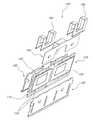
- FIGS. 1A-1Cschematically illustrate exploded views from various angles of a heat dissipation system compatible with certain embodiments described herein.
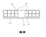
- FIGS. 2A-2Cschematically illustrate a FBDIMM.
- FIGS. 3A-3Cschematically illustrate various views of an example first segment of the heat dissipation system compatible with certain embodiments described herein.
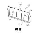
- FIGS. 4A-4Cschematically illustrate various views of an example second segment of the heat dissipation system compatible with certain embodiments described herein.
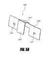
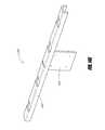
- FIGS. 5A-5Cschematically illustrate various views of an example third segment of the heat dissipation system compatible with certain embodiments described herein.
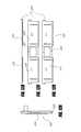
- FIG. 6schematically illustrates an exploded view of another heat dissipation system compatible with certain embodiments described herein.
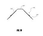
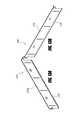
- FIGS. 7A-7Cschematically illustrate various views of another example third segment of the heat dissipation system compatible with certain embodiments described herein.
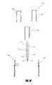
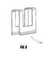
- FIG. 8schematically illustrates an example fastener compatible with certain embodiments described herein.
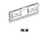
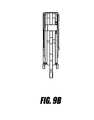
- FIGS. 9A-9Bschematically illustrate various views of an example assembled heat dissipation system on a module in accordance with certain embodiments described herein.
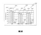
- FIG. 10is a bar graph illustrating the results of a simulation comparing the temperatures of the DRAM devices and one AMB of an FBDIMM with (i) a conventional heat dissipation system; and (ii) a heat dissipation system compatible with embodiments described herein.
- FIG. 11schematically illustrates an exploded view of another heat dissipation system compatible with certain embodiments described herein.
- FIGS. 12A-12Dschematically illustrate various views of another example first segment of the heat dissipation system of FIG. 11 compatible with certain embodiments described herein.
- FIGS. 13A-13Bschematically illustrate various views of another example second segment of the heat dissipation system of FIG. 11 compatible with certain embodiments described herein.
- FIGS. 14A-14Eschematically illustrate various views of another example third segment of the heat dissipation system of FIG. 11 compatible with certain embodiments described herein.
- FIG. 15schematically illustrates an example fastener of the heat dissipation system of FIG. 11 compatible with certain embodiments described herein.
- FIG. 16schematically illustrates an assembled heat dissipation system of FIG. 11 on the module in accordance with certain embodiments described herein.
- FIG. 17is a bar graph illustrating the results of a simulation comparing the temperatures of the DRAM devices and the AMB of an FBDIMM with a heat dissipation system compatible with embodiments described herein.
- FIG. 18is a flow chart of an example method of thermally coupling a heat dissipation system to an electronic module in accordance with certain embodiments described herein.
- Heat dissipation systems for electronic modulestypically include one or more heat spreaders which generally distribute heat evenly across the surface area of the electronic module (e.g., memory module), and they also tend to heat cooler components on the module, thereby causing these components to operate at slower speeds.
- heat dissipated by the AMBcan increase its temperature by 125° C. or more. This increased temperature not only degrades the performance of the AMB, but also affects its long-term reliability.
- Many existing heat dissipation systemstypically either cover the entire module on both sides, or are localized to draw heat from the AMB, which is typically the hottest component on the module.
- a heat dissipation systemwhich draws heat efficiently from the hotter components on the module and spreads the heat generally evenly over the electronic module, thereby significantly improving the thermal profile of the module.
- a heat dissipation systemis provided which provides for efficient heat transfer from one side of the module to the other side of the module.
- the heat dissipation systemcan achieve temperature differences across the components of the memory module (e.g., between memory devices and other memory devices and/or between memory devices and other components, such as an AMB) which are less than about 50 degrees Celsius.
- the heat dissipation systemcan achieve lower temperature differences across the components of the memory module, such as temperature differences which are less than about 40 degrees Celsius, or lower.
- a similar memory module not having a heat dissipation system in accordance with embodiments described hereinmay have temperature differences of up to about 60 degrees Celsius.
- the heat dissipation systemcan achieve differences between DRAM devices of the memory module of less than about 10 degrees Celsius.
- the heat dissipation systemcan achieve lower temperature differences across the memory devices of the memory module, such as temperature differences which are less than about 5 degrees Celsius, or lower.
- a similar memory module not having a heat dissipation system in accordance with embodiments described hereinmay have temperature differences between DRAM devices of up to 20 degrees Celsius.
- the temperature differences between DRAM devices of such a memory modulemay range from about 5 degrees Celsius to about 20 degrees Celsius.
- Certain embodiments described hereinadvantageously provide heat transfer from the module while keeping the overall thickness of the combined heat dissipation system and module sufficiently small to fit within the space available in conventional computer systems.
- the thickness of the combined heat dissipation system and moduleare from between about 3.4 millimeters and about 7.55 millimeters. In other embodiments, the thickness may be less than 3.4 millimeters or greater than 7.55 millimeters.
- certain embodiments described hereinadvantageously avoid heat from hotter components on the module from unduly heating cooler components on the module.
- DRAM casee.g., package
- temperatures greater than about 85 degrees Celsius, greater than 95 degrees Celsius, or greater than 40 degrees Celsius above the ambient temperaturemay cause undue heating and possible malfunction of the DRAM device.
- the temperature of the DRAM deviceis less than 85 degrees Celsius, less than 95 degrees Celsius, or less than 40 degrees greater than the ambient temperature.
- FIGS. 1A-1Cschematically illustrate exploded views from various angles of a heat dissipation system 100 compatible with certain embodiments described herein.
- the heat dissipation system 100is designed for use with an electronic module 110 having a first side 112 with a first plurality of electronic components 114 mounted thereon and a second side 116 with a second plurality of electronic components 118 mounted thereon.
- the heat dissipation system 100comprises a first segment 120 mountable on the module 110 to be in thermal communication with at least one electronic component of the first plurality of electronic components 114 .
- the heat dissipation system 100further comprises a second segment 130 mountable on the module 110 to be in thermal communication with at least one electronic component of the second plurality of electronic components 118 .
- the heat dissipation system 100also comprises a third segment 140 mountable on the module 110 to be in thermal communication with the first segment 120 and with the second segment 130 .
- the third segment 140provides a path through which heat flows from the first segment 120 to the second segment 130 .
- the first segment 120 , the second segment 130 , and/or the third segment 140are reversibly or removably mounted on the module 110 such that the first segment 120 , the second segment 130 , and/or the third segment 140 are removable from the module 110 without appreciably damaging the module 110 .
- the first segment, second segment and/or third segmentcan be repeatably mounted onto and dismounted from the module without appreciably damaging the module.
- the term “without appreciably damaging”has its broadest reasonable interpretation including but not limited to, resulting in no damage which affects the operability of the module or its components beyond the mere absence of the removed or dismounted segment.
- the heat dissipation system 100 schematically illustrated by FIGS. 1A-1Cis designed for use with a FBDIMM, such as the example FBDIMM schematically illustrated by FIGS. 2A-2C .
- the FBDIMMcomprises a printed-circuit board (“PCB”) 111 having a first side 112 and a second side 116 , with electronic components 114 , 118 mounted thereon.
- the electronic components 114 mounted on the first side 112comprise a plurality of memory (e.g., dynamic random-access memory or DRAM) devices and an advanced memory buffer (“AMB”).
- the memory devices on the first side 112are substantially the same as one another.
- the electronic components 118 mounted on the second side 116comprise a plurality of memory devices.
- the memory devices on the second side 116are substantially the same as one another and as the memory devices on the first side 112 .
- the FBDIMMalso comprises a plurality of edge connectors 113 along at least one edge of the printed-circuit board 111 .
- the edge connectors 113are configured to be electrically coupled to a corresponding plurality of electrical contacts of a module slot of the computer system with which the module 110 is to be used.
- the edge connectors 113are electrically coupled to the electronic components 114 , 118 of the module 110 by electrical conduits (not shown) of the printed-circuit board 111 .
- Examples of computer systems with which heat dissipation systems compatible with certain embodiments described herein may be usedinclude, but are not limited to, desktop computers, workstations, servers, telecom systems, and media centers.
- DIMMsdual in-line memory modules
- SO-DIMMssmall-outline DIMMs
- UDIMMsunbuffered DIMMs
- RDIMMsregistered DIMMs
- RBDIMMsrank-buffered DIMMs
- mini-DIMMsmini-DIMMs
- micro-DIMMsmicro-DIMMs.
- Memory devices compatible with certain embodiments described hereininclude, but are not limited to, random-access memory (RAM), dynamic random-access memory (DRAM), synchronous DRAM (SDRAM), and double-data-rate DRAM (e.g., SDR, DDR-1, DDR-2, DDR-3).
- the memory devicesmay comprise other types of memory elements such as static random-access memory (SRAM).
- SRAMstatic random-access memory
- memory devices having bit widths of 4, 8, 16, 32, as well as other bit widthsare compatible with certain embodiments described herein.
- Memory devices compatible with certain embodiments described hereinhave packaging which include, but are not limited to, thin small-outline package (TSOP), ball-grid-array (BGA), fine-pitch BGA (FBGA), micro-BGA ( ⁇ BGA), mini-BGA (mBGA), and chip-scale packaging (CSP), and three-dimensional packaging (e.g., chip stacks, die stacks, and dual die packaging).
- TSOPthin small-outline package
- BGAball-grid-array
- FBGAfine-pitch BGA
- ⁇ BGAmicro-BGA
- mini-BGAmini-BGA
- CSPchip-scale packaging
- three-dimensional packaginge.g., chip stacks, die stacks, and dual die packaging.
- the pluralities of memory devicesmay further include one or more non-volatile memory devices, such as, for example, flash memories.
- the pluralities of memory devices of certain embodimentsmay include both volatile and non-volatile memory devices.
- the plurality of memory devicesmay include one or more of DRAM, SRAM, and/or flash memory devices in some embodiments.
- FIGS. 3A-3Cschematically illustrate various views of the first segment 120 of the heat dissipation system 100 compatible with certain embodiments described herein.
- the first segment 120may also be referred to as a heat spreader.
- the first segment 120 of certain embodimentscomprises a thermally conductive material (e.g., metals, copper, aluminum, copper alloy, aluminum alloy, metal matrix composites, carbon composites).
- the first segment 120comprises a single integral element or piece of material which is formed into a configuration as described herein.
- the first segment 120can be formed from a single sheet of metal shaped (e.g., cut, bent, or both cut and bent) into a configuration as described herein.
- the first segment 120comprises a plurality of elements which are connected together in a configuration as described herein.
- the first segment 120comprises a portion 122 that is positionable to be in thermal communication with one or more of the electronic components 114 on the first side 112 of the module 110 .
- the portion 122comprises a substantially flat or planar portion positionable to be in thermal communication with the first plurality of electronic components 114 on the first side 112 of the module 110 .
- the portion 122is not flat or planar, but is contoured to fit with and to be in thermal communication with the first plurality of electronic components 114 mounted on the first side 112 of the module 110 .
- the heat dissipation system 100 of certain embodimentsfurther comprises a thermally conductive material 150 ( FIG. 1A ) positionable between the first segment 120 and the first plurality of electronic components 114 to improve thermal conductivity between the first segment 120 and the first plurality of electronic components 114 .
- the thermally conductive material 150improves the thermal conductivity between the portion 122 and the electronic components 114 .
- Thermally conductive materials compatible with certain embodiments described hereininclude, but are not limited to, thermal pads (e.g., a gap-filling material or a phase-changing material), thermally conductive adhesives, and thermal grease or paste.
- thermal padse.g., a gap-filling material or a phase-changing material
- thermally conductive adhesivese.g., a thermally conductive adhesives
- thermal grease or pastee.g., thermal grease or paste.
- the first segment 120(or first heat spreader) comprises a first heat dissipation portion 124 in thermal communication with at least one of the plurality of electronic components 114 and a second heat dissipation portion 126 extending along the side 112 of the module 110 .
- the first heat dissipation portion 124 and the portion 122are the same, or overlap one another at least partially.
- the second heat dissipation portion 126is in thermal communication with the first heat dissipation portion 124 .
- At least one of the plurality of electronic components 114 on the electronic module 110is positioned between the second heat dissipation portion 126 and the side 112 and is spaced away from the second heat dissipation portion 126 .
- one or more passive electrical componentsare mounted on the side 112 and the second heat dissipation portion 126 is spaced away from the one or more passive electrical components.
- the second portion 126 of certain embodimentsis configured so as to generally conform to the module 110 and/or one or more of the plurality of electronic components on the module 110 .
- the second portion 126is configured to remove heat conducted by the first portion 124 away from the module 110 .
- the second portion 126extends generally away from the first portion 124 and provides a thermal conduit for heat from the first side 112 of the module 110 away from the module 110 .
- the second portion 126removes heat conducted by the first portion 124 by increasing the heat transfer area of the first segment 120 .
- the second portion 126extends along an edge of the module 110 having one or more connectors 113 as described above so as to provide a low profile for the heat dissipation system 100 when the first segment 120 is mounted on the module 110 .
- the second portion 126 of certain embodimentsis configured so as to avoid interaction with and/or to protect components (not shown) on the first side 112 of the module 110 .
- the second portion 126may be positioned to avoid contacting passive components such as resistors and capacitors on the side 112 of the module 110 .
- the second portion 126may be positioned to avoid contacting active components such as transistors on the side 112 of the module 110 .
- the second portion 126is configured so as to avoid physical interaction with the components.
- the second portion 126is configured to avoid electrical interaction with the components.
- the second portion 126is configured to avoid both physical and electrical interaction with the components.
- first portion 124 and/or the second portion 126comprises a plurality of generally planar portions.
- first portion 124is contoured to fit with and to be in thermal communication with the first plurality of electronic components 114 mounted on the first side 112 of the module 110 .
- FIGS. 4A-4Cschematically illustrate various views of the second segment 130 of the heat dissipation system 100 compatible with certain embodiments described herein.
- the second segment 130may also be referred to as a heat spreader.
- the second segment 130 of certain embodimentscomprises a thermally conductive material (e.g., metals, copper, aluminum, copper alloy, aluminum alloy, metal matrix composites, carbon composites).
- the second segment 130comprises a single integral element or piece of material which is formed into a configuration as described herein.
- the second segment 130can be formed from a single sheet of metal shaped (e.g. cut, bent, or both cut and bent) into a configuration as described herein.
- the second segment 130comprises a plurality of elements which are connected together in a configuration as described herein.
- the second segment 130comprises a portion 132 that is positionable to be in thermal communication with one or more of the electronic components 118 on the second side 116 of the module 110 .
- the portion 132comprises a substantially flat or planar portion positionable to be in thermal communication with the second plurality of electronic components 118 on the second side 116 of the module 110 .
- the portion 132is not flat or planar, but is contoured to fit with and to be in thermal communication with the second plurality of electronic components 118 mounted on the second side 116 of the module 110 .
- the heat dissipation system 100 of certain embodimentsfurther comprises a thermally conductive material 152 ( FIG. 1B ) positionable between the second segment 130 and the second plurality of electronic components 118 which can be generally similar to the thermally conductive materials described herein.
- the second segment 130(or second heat spreader) comprises a first heat dissipation portion 134 in thermal communication with at least one of the plurality of electronic components 118 and a second heat dissipation portion 136 extending along the side 116 of the module 110 .
- the second heat dissipation portion 136is in thermal communication with the first heat dissipation portion 134 .
- At least one of the plurality of electronic components 118 on the electronic module 110is positioned between the second heat dissipation portion 136 and the side 116 and is spaced away from the second heat dissipation portion 136 .
- one or more passive electrical componentsare mounted on the side 116 and the second heat dissipation portion 136 is spaced away from the one or more passive electrical components.
- the second portion 136 of certain embodimentsis configured so as to generally conform to the module 110 and/or one or more of the plurality of electronic components on the module 110 .
- the second portion 136is configured to remove heat conducted by the first portion 134 away from the module 110 .
- the second portion 136extends generally away from the first portion 134 and provides a thermal conduit for heat from the second side 116 of the module 110 away from the module 110 .
- the second portion 136removes heat conducted by the first portion 134 by increasing the heat transfer area of the second segment 130 .
- the second portion 136extends along an edge of the module 110 having one or more connectors 113 as described above so as to provide a low profile for the heat dissipation system 100 when the second segment 130 is mounted on the module 110 .
- the second portion 136is configured so as to avoid interaction with and/or to protect components (not shown) on the second side 116 of the module 110 .
- the second portion 136may be positioned to avoid contacting passive components such as resistors and capacitors on the side 116 of the module 110 .
- the second portion 136may be positioned to avoid contacting active components such as transistors on the side 116 of the module 110 .
- the second portion 136is configured so as to avoid physical interaction with the components.
- the second portion 136is configured to avoid electrical interaction with the components.
- the second portion 136is configured to avoid both physical and electrical interaction with the components.
- first portion 134 and/or the second portion 136comprises a plurality of generally planar portions.
- first portion 134is contoured to fit with and to be in thermal communication with the second plurality of electronic components 118 mounted on the second side 116 of the module 110 .
- FIGS. 5A-5Cschematically illustrate various views of an example third segment 140 of the heat dissipation system 100 compatible with certain embodiments described herein.
- the third segment 140is mountable on the module 110 to be in thermal communication with the first segment 120 and with the second segment 130 and provides a path through which heat flows from the first segment 120 to the second segment 130 .
- the third segment 140comprises a thermally conductive material.
- the third segment 140comprises copper.
- the third segment 140comprises a composite material.
- the third segment 140can comprise aluminum, copper, copper alloy, aluminum alloy, metal matrix composites, carbon composites.
- the third segmentcomprises copper having a thermal conductivity of 401 W/(m ⁇ K) at 300 degrees Kelvin. In other embodiments, the third segment 140 comprises aluminum having a thermal conductivity of 237 W/(m ⁇ K) at 300 degrees Kelvin. In certain embodiments, the third segment 140 comprises a material that is more thermally conductive that the first segment 120 and/or second segment 130 . In other embodiments, the third segment 140 can comprise a material that is similarly thermally conductive or less thermally conductive that the first segment 120 and/or the second segment 130 .
- the third segment 140extends from the first segment 120 over or across an edge of the module 110 to the second segment 130 . In certain embodiments, the third segment 140 extends over or across the top (non-connector) edge of the module 110 . In some embodiments, the third segment 140 extends over or across multiple edges or different edges of the module 110 , such as, for example, one or more sides of the module 110 . In certain embodiments, the third segment 140 extends over or across only a portion of an edge of the module 110 , such as a center portion of an edge of the module 110 . In other embodiments, the third segment 140 extends over or across substantially an entire edge of the module 110 .
- the third segment 140 of some embodimentscomprises a single integral element or piece of material which is formed into a configuration as described herein.
- the third segment 140can be formed from a single sheet of metal shaped (e.g., cut, bent, or both cut and bent) into a configuration as described herein.
- Various ranges of thicknesses of the sheetare compatible with certain embodiments described herein, including but not limited to between 0.3 millimeter and 3 millimeters, between 0.3 millimeter and 1 millimeter, between 0.35 millimeter and 1 millimeter, and between 0.3 millimeter and 0.7 millimeter. Higher or lower thicknesses are possible in other configurations in accordance with certain embodiments described herein.
- the third segment 140comprises a first portion 143 positionable to be in thermal communication with the first segment 120 and a second portion 145 positionable to be in thermal communication with the second segment 130 .
- the third segment 140also comprises a third portion 147 which connects the first and second portions 143 , 145 .
- the first portion 143is positionable to be in thermal communication with at least one of the first plurality of electronic components 114 .
- the second portion 145is positionable to be in thermal communication with at least one of the second plurality of electronic components 118 in certain embodiments.
- the first portion 143is positionable so as to be in thermal communication with one or more of the plurality of electronic components 114 of the module 110 which dissipate a relatively large amount of heat in comparison to the other electronic components on the module 110 .
- the first portion 143may be positioned to be in thermal communication with the AMB 117 of the module 110 .
- this configurationallows heat from the relatively hotter component(s) (e.g., the AMB 117 ) to be transferred to the second side 116 of the module 110 in a relatively efficient manner without, for example, substantially heating one or more of the other components on the first side 112 of the module 110 .
- the first portion 143 and/or the second portion 145 of certain embodimentsare generally planar.
- the first portion 143 and/or the second portion 145may be contoured or non-planar in other embodiments.
- the first portion 143 and/or the second portion 145 in some embodimentsare shaped so as to define at least one channel or region between the first portion 143 and the first segment 120 and/or between the second portion 145 and the second segment 130 .
- Such a configurationcan, for example, allow air to flow through the channel or region between the first portion 143 and the first segment 120 and/or between the second portion 145 and the second segment in some embodiments so as to cool the module 110 .
- the first portion 143 and/or second portion 145comprise substantially flat surfaces.
- the first portion 143 and/or second portion 145comprise contoured surfaces.
- the first portion 143is positionable such that the first segment 120 is between the first portion 143 and the first side 112 of the module 110 . In certain other embodiments, the first portion 143 is positionable between the first segment 120 and the first side 112 of the module 110 .
- the second portion 145is positionable such that the second segment 130 is between the second portion 145 and the second side 116 of the module 110 . In certain other embodiments, the second portion 145 is positionable between the second segment 130 and the second side of the module 110 .
- the third segment 140comprises a plurality of elements in a configuration as described herein.
- FIG. 6schematically illustrates an exploded view of another heat dissipation system 100 compatible with certain embodiments described herein having a third segment 140 which comprises two elements 142 , 144 .
- the two elements 142 , 144are similar to one another.
- the elementsmay be shaped differently from one another and/or there may be more than two elements.
- one or more of the elementsmay be shaped to accommodate or be accommodated by certain parts of the module 110 , the first segment 120 , and/or the second segment 130 .
- FIGS. 7A-7Cschematically illustrate various views of one element 142 of the third segment 140 of the heat dissipation system 100 of FIG. 6 in accordance with certain embodiments described herein.
- the third segment 140can comprise one or more holes or cut-outs 146 .
- the cut-outs 146can be shaped, in certain embodiments, so as to be accommodated by one or more features on, for example, the module 110 , the first segment 120 , and/or the second segment 130 (e.g., FIG. 6 ).
- the cut-outs 146 and the corresponding features they accommodate, such as the notches 148are configured so as to provide a flush surface, such as a flush top edge when the heat dissipation system 100 is assembled on the module.
- the cut-out 146 and notch 148 arrangementis configured to limit the overall height of the heat dissipation system 100 and module 110 assembly.
- the limited heightallows the module 110 with the mounted heat dissipation system 100 to conform to certain height requirements so as to, for example, fit to certain form factors and/or to meet certain industry standards (e.g., a JEDEC standard).
- the combined height of the module 110 and the heat dissipation system 100 assemblyis about 18.3 millimeters. In other embodiments, the combined height is about 30 millimeters. In various embodiments, the combined height may be between about 18.3 millimeters to about 30 millimeters. Shorter or taller combined heights are possible in other configurations in accordance with certain embodiments described herein.
- a thermally conductive material(not shown) is positionable between the first segment 120 and the third segment 140 to improve thermal conductivity between the first segment 120 and the third segment 140 .
- a thermally conductive material(not shown) is positionable between the second segment 130 and the third segment 140 to improve thermal conductivity between the second segment 130 and the third segment 140 .
- the thermally conductive material between the first segment 120 and the third segment 140comprises the same material as the thermally conductive material between the second segment 130 and the third segment 140 .
- different thermally conductive materialsare used.
- the thermally conductive material between the first segment 120 and the third segment 140 and/or the thermally conductive material between the second segment 130 and the third segment 140can comprise appropriate materials and which would be within the knowledge of those of skill in the art. Examples of such materials are described herein.
- a thermally conductive material(not shown) is positionable between the first portion 143 and the at least one of the first plurality of electronic components 114 to improve thermal conductivity between the first portion 143 and the at least one of the first plurality of electronic components 114 .
- a thermally conductive material(not shown) is positionable between the second portion 145 and the at least one of the second plurality of electronic components 118 to improve thermal conductivity between the second portion 145 and the at least one of the second plurality of electronic components 118 .
- the thermally conductive materialmay be, for example, one of the thermally conductive materials described herein.
- the first portion 143is positionable to be in thermal communication with the advanced memory buffer 117 .
- a thermally conductive materialis positionable between the first portion 143 and the advanced memory buffer 117 to improve thermal conductivity between the first portion 143 and the advanced memory buffer 117 .
- the third segment 140comprises at least one securing feature 141 which mechanically mates with at least one corresponding securing feature 121 , 131 on at least one of the first segment 120 and/or the second segment 130 .
- the at least one securing feature 141 of the third segment 140comprises a recess and the at least one corresponding securing feature 121 , 131 on the at least one of the first segment 120 and/or the second segment 130 comprises a protrusion.
- other types of securing featuresmay be used such as a friction mechanism.
- the securing featuresmay be generally reversed.
- the recessmay be included on the first segment 120 and/or second segment 130 while the protrusion may be included on the third segment 140 .
- the first segment 120 , the second segment 130 , and the third segment 140can comprise separate elements which are detachable from one another.
- the first segment 120 , the second segment 130 , and the third segment 140together comprise a single integral element.
- other configurationsare possible.
- the first and second segments 120 , 130may comprise a single integral element and the third segment 140 may comprise a separate integral element.
- the module 110 of certain embodimentshas a length and a height and the first segment 120 extends substantially along the full length and the full height of the module 110 .
- the second segment 130extends substantially along the full length and the full height of the module 110 .
- first, second and third segments 120 , 130 , 140may comprise different materials from one another.
- the first and second segments 120 , 130comprise aluminum and the third segment 140 comprises copper.
- the first, second and third segments 120 , 130 , 140may comprise the same material.
- the heat dissipation system 100further comprises one or more fasteners 160 (e.g., clips) mountable on the first segment 120 , the second segment 130 , and/or the third segment 140 .
- the fasteners 160of certain embodiments apply force to one or more of the first segment 120 , the second segment 130 , and the third segment 140 so that the first segment 120 , the second segment 130 , and the third segment 140 are mechanically coupled to the module.
- the fasteners 160can comprise metal such as, for example, stainless steel.
- the fasteners 160comprise other materials such as, for example, plastic.
- FIG. 8schematically illustrates an example fastener 160 compatible with certain embodiments described herein.
- the fastener 160has a general “U”-shape which fits over respective portions of one or more of the first segment 120 , the second segment 130 , and the third segment 140 .
- the fastener 160provides a tension spring force which holds the first segment 120 and the second segment 130 in place on either side 112 , 116 of the module 110 .
- the fastener 160comprises one or more protrusions (not shown). These protrusions can mate with corresponding recesses on one or more of the first segment 120 , the second segment 130 , and the third segment 140 thereby advantageously increasing the stability of the heat dissipation system 100 .
- the fasteners 160comprise recesses which mate with corresponding protrusions on one or more of the first segment 120 , the second segment 130 , and the third segment 140 .
- Certain embodiments of the fastener 160include a cut-out portion.
- the fastener 160may be designed so as to accommodate one or more notches 148 on the memory module 110 and/or other features of the heat dissipation system 100 .
- the fastener 160may not include a cut-out portion.
- FIGS. 1A-1Cschematically illustrate an exploded view of an example configuration of fasteners 160 with the first segment 120 , the second segment 130 , the third segment 140 , and the module 110 .
- fasteners 160or other structures for holding the portions of the heat dissipation system 100 on the module 110 are also compatible with certain embodiments described herein.
- adhesivescan be used as fasteners 160 to bond the portions of the heat dissipation system 100 together with the module 110 .
- FIGS. 9A-9Bschematically illustrate various views of an example assembled heat dissipation system 100 on the module 110 in accordance with certain embodiments described herein.
- the heat dissipation system 100advantageously provides superior removal of heat from the module 110 .
- FIG. 10is a bar graph 1000 illustrating the results of a simulation comparing the temperatures of the DRAM devices and the AMB of an FBDIMM with (i) a conventional heat dissipation system; and (ii) a heat dissipation system compatible with embodiments described herein. Temperature comparisons are shown for the AMB, a DRAM upstream with respect to the direction of air flow, and a DRAM downstream with respect to the direction in which air flows.
- the temperature difference (DeltaT) 1016 , 1026 , 1036 between the conventional heat dissipation system 1012 , 1022 , 1032 and the heat dissipation system 1014 , 1024 , 1034 compatible with embodiments described hereinis also illustrated in the bar graph for each of the three types of characterized devices (AMB, upstream DRAM, and downstream DRAM).
- the FBDIMMis an 8 GB FBDIMM operating at 667 MHz.
- FIG. 10illustrates that in certain embodiments the heat dissipation system 100 provides significantly improved cooling over conventional heat spreaders.
- the heat dissipation system 100 of certain embodimentscan provide temperatures which are between about 5 degrees Celsius and about 7 degrees Celsius lower than temperatures provided by conventional heat dissipation systems.
- FIG. 11schematically illustrates an exploded view of another heat dissipation system 200 compatible with certain embodiments described herein.
- the heat dissipation system 200is designed for use with an electronic module 110 having a first side 112 with a first plurality of electronic components 114 mounted thereon and a second side 116 with a second plurality of electronic components 118 mounted thereon.
- the heat dissipation system 100comprises a first segment 220 mountable on the module 110 to be in thermal communication with at least one electronic component of the first plurality of electronic components 114 .
- the heat dissipation system 100further comprises a second segment 230 mountable on the module 110 to be in thermal communication with at least one electronic component of the second plurality of electronic components 118 .
- the heat dissipation system 100also comprises a third segment 240 mountable on the module 110 to be in thermal communication with the first segment 220 and with the second segment 230 .
- the third segment 240provides a path through which heat flows from the first segment 220 to the second segment 230 .
- the third segment 240comprises a portion 242 in thermal communication with at least one electronic component of the first plurality of electronic components 114 as described below with respect to FIGS. 13A-13E .
- FIGS. 12A-12Dschematically illustrate various views of another example first segment 220 of the heat dissipation system 200 of FIG. 11 compatible with certain embodiments described herein.
- the first segment 220may also be referred to as a heat spreader.
- the first segment 220 of certain embodimentscomprises a thermally conductive material (e.g., metals, copper, aluminum, copper alloy, aluminum alloy, metal matrix composites, carbon composites).
- the first segment 220comprises a single integral element or piece of material which is formed into a configuration as described herein.
- the first segment 220can be formed from a single sheet of metal shaped (e.g., cut, bent, or both cut and bent) into a configuration as described herein.
- the first segment 220comprises a plurality of elements which are connected together in a configuration as described herein.
- the heat dissipation system 200further comprises a thermally conductive material (not shown) positionable between the first segment 220 and the first plurality of electronic components 114 to improve thermal conductivity between the first segment 220 and the first plurality of electronic components 114 .
- the thermally conductive materialimproves the thermal conductivity between the first segment 220 and the electronic components.
- Thermally conductive materials compatible with certain embodiments described hereininclude, but are not limited to, thermal pads (e.g., a gap-filling material or a phase-changing material), thermally conductive adhesives, and thermal grease or paste.
- thermal padse.g., a gap-filling material or a phase-changing material
- thermally conductive adhesivese.g., a thermally conductive adhesives
- thermal grease or pastee.g., thermal grease or paste.
- the first segment 220is configured to cause heat flowing from one or more electronic components on the module 110 to be at least partially thermally decoupled from one or more of the first segment 220 and the second segment 230 .
- the first segment 220further comprises a cut-out or hole 224 which can be configured to cause heat coming from the AMB 117 on the first side 112 of the module 110 to flow generally into the third segment 240 (described below) and away from the AMB 117 , before flowing into one or more of the first segment 220 and second segment 230 such that heat from the AMB 117 is dissipated across one or more of the first segment 220 and the second segment 230 .
- the AMB 117is in direct thermal communication with the third segment 240 which is in turn in thermal communication with one or more of the first segment 220 and the second segment 230 so that heat from the AMB 117 is dissipated across one or more of the first segment 220 and the second segment 230 .
- the cut-out or hole 224may, in certain embodiments, be configured to substantially thermally isolate the first segment 220 from at least one electronic component on the first side 112 of the module 110 .
- the hole 224may be configured to substantially thermally isolate the first segment 220 from the AMB 117 .
- the hole 224thermally isolates the AMB 117 on the first side 112 from the memory devices on the first side 112 , thereby advantageously reducing over-heating of these memory devices due to heat from the AMB 117 .
- the first segment 220(or first heat spreader) comprises a first portion 222 positionable to be in thermal communication with at least one of the plurality of electronic components 114 on the first side 112 of the module 110 .
- the first portion 222comprises a substantially flat or planar portion positionable to be in thermal communication with the first plurality of electronic components 114 on the first side 112 of the module 110 .
- the first portion 222is not flat or planar, but is contoured to fit with and to be in thermal communication with the first plurality of electronic components 114 mounted on the first side 112 of the module 110 .
- the first portion 222 of certain embodimentsis configured to provide heat dissipation from the one or more electronic components on the first side 112 of the module 110 .
- the first segment 220 of certain embodimentsfurther comprises a second portion 226 extending along the side 112 of the module 110 and the second portion 226 is in thermal communication with the first portion 222 .
- the second portion 226can be positioned such that it extends generally toward the side 112 of the module 110 when mounted on the module 110 .
- the configuration of the second portion 226can provide improved structural integrity when the first segment 220 is mounted on the module 110 .
- the second portion 226may prevent the first portion 222 of the first segment 220 from bending towards and/or up against the module when pressure is placed on the first portion 222 in the direction of the module 110 .
- at least one of the plurality of electronic components 114 on the electronic module 110is positioned between the second portion 226 and the side 112 and spaced away from the second portion 226 .
- the second portion 226is configured to remove heat conducted by the first portion 222 away from the module 110 .
- the second portion 226extends generally away from the portion 242 and provides a thermal conduit for heat from the first side 112 of the module 110 away from the module 110 .
- the second portion 226removes heat conducted by the first portion 222 by increasing the heat transfer area of the first segment 220 .
- the second portion 226extends along an edge of the module 110 having one or more connectors 113 as described above so as to provide a low profile.
- the second portion 226mechanically strengthens the third segment 240 .
- the second portion 226is configured so as to avoid interaction with and/or to protect components (not shown) on the first side 112 of the module 110 .
- the second portion 226may be positioned to avoid contacting passive components such as resistors and capacitors on the side 112 of the module 110 .
- the second portion 226may be positioned to avoid contacting active components such as transistors on the side 112 of the module 110 .
- the second portion 226is configured so as to avoid physical interaction with the components.
- the second portion 226is configured to avoid electrical interaction with the components.
- the second portion 226is configured to avoid both physical and electrical interaction with the components.
- the first portion 222 and/or the second portion 226comprises a plurality of generally planar portions.
- the first portion 222is contoured to fit with and to be in thermal communication with the first plurality of electronic components 114 mounted on the first side 112 of the module 110 .
- the second portion 226is contoured so as to avoid interaction with one or more of the first plurality of components 114 , such as one or more passive components, on the first side 112 of the module 110 .
- FIGS. 13A-13Bschematically illustrate various views of another example second segment 230 of the heat dissipation system 200 of FIG. 11 compatible with certain embodiments described herein.
- the heat dissipation system 200can include a second segment 230 mountable on the module 110 to be in thermal communication with at least one electronic component of the second plurality of electronic components 118 , as illustrated in FIG. 11 .
- the second segment 230 of certain embodimentscan be similar to the second segment 130 described above with respect to FIGS. 4A-4C .
- the second segment 230can be generally similar to the first segment 220 described above with respect to FIGS. 12A-12D , but may, in certain embodiments, not include a cut-out or hole 224 .
- the heat dissipation system 200further comprises a thermally conductive material positionable between the second segment 230 and the second plurality of electronic components 118 which can be generally similar to the thermally conductive materials described herein.
- the second segment 230(or second heat spreader) of certain embodiments comprises a first portion 234 in thermal communication with at least one of the plurality of electronic components 118 and a second portion 236 extending along the side 116 of the module 110 .
- the first and second portion 234 , 236can be configured to provide heat dissipation from the one or more electrical components on the second side 116 of the module 110 .
- the first and second portions 234 , 236are generally similar to the first and second portions 222 , 226 described above with respect to the first segment 220 .
- the first and second portions 234 , 236can be generally similar to the first and second portions 124 , 126 described above with respect to the first segment 120 of FIGS. 3A-3C .
- FIGS. 14A-14Eschematically illustrate various views of another example third segment 240 of the heat dissipation system 200 of FIG. 11 compatible with certain embodiments described herein.
- the third segment 240is mountable on the module 110 to be in thermal communication with one or more of the first segment 220 and with the second segment 230 .
- the third segment 240provides a path through which heat flows from the first segment 220 to the second segment 230 .
- the third segment 240can comprise a thermally conductive material.
- the third segment 240comprises a composite material.
- the third segment 240comprises copper.
- the third segment 240comprises aluminum, copper alloy, aluminum alloy, metal matrix composites, carbon composites. In certain embodiments, the third segment 240 comprises a material that is more thermally conductive that the first segment 220 and/or second segment 230 . In other embodiments, the third segment 240 can be comprised of a material that is of a similarly thermally conductive or less thermally conductive than the first segment 220 and/or the second segment 230 .
- the third segment 240comprises a portion 242 in thermal communication with at least one electronic component of the first plurality of electronic components.
- the portion 242 of the third segment 240is in thermal communication with an advanced memory buffer 117 of the first plurality of electronic components.
- the portion 242 of the third segment 240may be in communication with other components of the module 110 instead of or in addition to the AMB 117 .
- the portion 242 of the third segment 240is substantially flat or planar.
- the third segment 240comprises a substantially flat or planar portion 244 running substantially along the entire length of the edge of the module 110 .
- the first segment 220comprises a hole 224 .
- At least a portion of the third segment 240is mountable over the hole 224 in certain embodiments.
- at least one electronic component of the first plurality of electronic components 114e.g., the AMB 117
- the third segment 240extends from the first segment 220 over or across an edge of the module 110 to the second segment 230 . In certain embodiments, the third segment 240 extends over or across the top (e.g., non-connector) side of the module. In some embodiments, the third segment 240 extends over or across multiple edges or different edges of the module 110 , such as, for example, one or more sides of the module 110 . In certain embodiments, the third segment 240 extends over or across only a portion of an edge of the module 110 , such as a center portion of an edge of the module 110 . In other embodiments, the third segment 240 extends over or across substantially an entire edge of the module 110 .
- the third segment 240comprises a single integral element or piece of material which is formed into a configuration as described herein.
- the third segment 240can be formed from a single sheet of metal shaped (e.g., cut, bent, or both cut and bent) into a configuration as described herein.
- Various ranges of thicknesses of the sheetare compatible with certain embodiments described herein, including but not limited to between 0.3 millimeter and 3 millimeters, between 0.3 millimeter and 1 millimeter, between 0.35 millimeter and 1 millimeter, and between 0.3 millimeter and 0.7 millimeter. Higher or lower thicknesses are possible in other configurations in accordance with certain embodiments described herein.
- the third segment 240comprises a plurality of elements which can be connected together.
- the third segment 240may be shaped to accommodate certain parts of the module 110 , the first segment 220 , and/or the second segment 230 .
- the third segment 240can comprise one or more holes or cut-outs 246 .
- the cut-outs 246can be shaped, in certain embodiments, so as to be accommodated by one or more features on, for example, the module 110 , the first segment 220 , and/or the second segment 230 .
- the cut-outs 246can be shaped to such that the element 240 is accommodated by one or more notches on the module 110 , the first segment 220 , and the second segment 230 .
- the cut-outs 246 and the corresponding features they are accommodated by, such as the notchesare configured so as to provide a flush surface, such as a flush top edge when the heat dissipation system 200 is assembled on the module.
- FIG. 15schematically illustrates an example fastener 250 of the heat dissipation system 200 of FIG. 11 compatible with certain embodiments described herein.
- a fastener 250may be mountable on the third segment 240 to apply force to the third segment 240 so that the third segment 240 is mechanically coupled to the module.
- the fastenercomprises a cut-out portion 252 .
- the cut-out portion 252provides for enhanced heat removal from one or more of the electronic components on the module 110 .
- the cut-out portion 252provides for enhanced heat removal from the AMB 117 on the module 110 .
- the cut-out portion 252 of certain embodimentsreduces the thermal resistance from the one or more electronic components (e.g., the AMB 117 ) to the third segment 240 and/or to one or more other portions of the heat dissipation system 200 such as the first segment 220 or the second segment 230 .
- the fasteneris made of metal, such as, for example, stainless steel.
- FIG. 16schematically illustrates an assembled heat dissipation system 200 of FIG. 11 on the module 110 in accordance with certain embodiments described herein.
- FIG. 17is a bar graph 1700 illustrating the results of a simulation comparing the temperatures of the DRAM devices 1702 , 1712 and the AMB 1704 , 1714 of an FBDIMM with a heat dissipation system compatible with embodiments described herein.
- Results 1706 , 1716 in degrees Celsiusare shown for simulation results corresponding to ambient temperatures of 25 degrees Celsius and 35 degrees Celsius, respectively.
- the temperature of the AMB 1704is about 78 degrees Celsius and the temperature of the DRAM devices 1702 is about 72 degrees Celsius.
- the temperature of the AMB 1714is about 88 degrees Celsius and the temperature of the DRAM devices 1712 is about 82 degrees Celsius.
- FIG. 18is a flow chart of an example method 1800 of thermally coupling a heat dissipation system 100 to an electronic module 110 in accordance with certain embodiments described herein. Although described with respect to the heat dissipation 100 , the method 1800 may be compatible with any of the heat dissipation systems described herein or with some other heat dissipation system.
- the electronic module 110 of certain embodimentshas a first side 112 with a first plurality of electronic components 114 mounted thereon and a second side 116 with a second plurality of electronic components 118 mounted thereon.
- the method 1800 of certain embodimentscomprises mounting a first segment 120 on the module 112 to be in thermal communication with at least one electronic component of the first plurality of electronic components 114 at operational block 1802 .
- the method 1800further comprises mounting a second segment 130 on the module 112 to be in thermal communication with at least one electronic component of the second plurality of electronic components 118 at operational block 1804 .
- the method 1800may comprise mounting a third segment 140 on the module 112 to be in thermal communication with the first segment 112 and with the second segment 130 , the third segment 140 providing a path through which heat flows from the first segment 120 to the second segment.
- the method 1800further comprises mounting a fastener 160 on the module 110 .
- the fastener 160 of certain embodimentsis configured to apply force to one or more of the first segment 120 , the second segment 130 , and the third segment 140 so that the first segment 120 , the second segment 130 , and the third segment 140 are mechanically coupled to the module.
- one or more of the first segment 120 , the second segment 130 , and the third segment 140are reversibly or removably mounted on the module 112 such that the respective segments 120 , 130 , 140 are removable from the module 112 without appreciably damaging the module 112 .
- One or more of the operational blocks 1802 , 1804 , 1806 shown in FIG. 18may not be included in certain other embodiments. In yet other embodiments, one or more additional operational blocks may be included in addition to, or instead of the operational blocks 1802 , 1804 , 1806 of FIG. 18 .
Landscapes
- Engineering & Computer Science (AREA)
- Physics & Mathematics (AREA)
- Condensed Matter Physics & Semiconductors (AREA)
- General Physics & Mathematics (AREA)
- Computer Hardware Design (AREA)
- Microelectronics & Electronic Packaging (AREA)
- Power Engineering (AREA)
- Chemical & Material Sciences (AREA)
- Materials Engineering (AREA)
- Cooling Or The Like Of Electrical Apparatus (AREA)
- Cooling Or The Like Of Semiconductors Or Solid State Devices (AREA)
Abstract
Description
Claims (25)
Priority Applications (2)
| Application Number | Priority Date | Filing Date | Title |
|---|---|---|---|
| US12/432,591US8018723B1 (en) | 2008-04-30 | 2009-04-29 | Heat dissipation for electronic modules |
| US13/205,477US8705239B1 (en) | 2008-04-30 | 2011-08-08 | Heat dissipation for electronic modules |
Applications Claiming Priority (2)
| Application Number | Priority Date | Filing Date | Title |
|---|---|---|---|
| US4915308P | 2008-04-30 | 2008-04-30 | |
| US12/432,591US8018723B1 (en) | 2008-04-30 | 2009-04-29 | Heat dissipation for electronic modules |
Related Child Applications (1)
| Application Number | Title | Priority Date | Filing Date |
|---|---|---|---|
| US13/205,477ContinuationUS8705239B1 (en) | 2008-04-30 | 2011-08-08 | Heat dissipation for electronic modules |
Publications (1)
| Publication Number | Publication Date |
|---|---|
| US8018723B1true US8018723B1 (en) | 2011-09-13 |
Family
ID=44544804
Family Applications (2)
| Application Number | Title | Priority Date | Filing Date |
|---|---|---|---|
| US12/432,591Active2029-11-12US8018723B1 (en) | 2008-04-30 | 2009-04-29 | Heat dissipation for electronic modules |
| US13/205,477Active2029-07-13US8705239B1 (en) | 2008-04-30 | 2011-08-08 | Heat dissipation for electronic modules |
Family Applications After (1)
| Application Number | Title | Priority Date | Filing Date |
|---|---|---|---|
| US13/205,477Active2029-07-13US8705239B1 (en) | 2008-04-30 | 2011-08-08 | Heat dissipation for electronic modules |
Country Status (1)
| Country | Link |
|---|---|
| US (2) | US8018723B1 (en) |
Cited By (30)
| Publication number | Priority date | Publication date | Assignee | Title |
|---|---|---|---|---|
| US20100243203A1 (en)* | 2009-03-24 | 2010-09-30 | Fu Zhun Precision Industry (Shen Zhen) Co., Ltd. | Cooling device for add-on card |
| US20110051353A1 (en)* | 2009-08-25 | 2011-03-03 | Fu Zhun Precision Industry (Shen Zhen) Co., Ltd. | Heat dissipation device for memory module |
| US20140211405A1 (en)* | 2013-01-30 | 2014-07-31 | Adata Technology Co., Ltd. | Safety detachable assembly and memory module using the same |
| US8930647B1 (en) | 2011-04-06 | 2015-01-06 | P4tents1, LLC | Multiple class memory systems |
| USD722601S1 (en)* | 2013-01-30 | 2015-02-17 | Adata Technology Co., Ltd. | Detachable assembly of memory module |
| US9158546B1 (en) | 2011-04-06 | 2015-10-13 | P4tents1, LLC | Computer program product for fetching from a first physical memory between an execution of a plurality of threads associated with a second physical memory |
| US9164679B2 (en) | 2011-04-06 | 2015-10-20 | Patents1, Llc | System, method and computer program product for multi-thread operation involving first memory of a first memory class and second memory of a second memory class |
| US9170744B1 (en) | 2011-04-06 | 2015-10-27 | P4tents1, LLC | Computer program product for controlling a flash/DRAM/embedded DRAM-equipped system |
| US9176671B1 (en) | 2011-04-06 | 2015-11-03 | P4tents1, LLC | Fetching data between thread execution in a flash/DRAM/embedded DRAM-equipped system |
| USD761744S1 (en)* | 2012-07-18 | 2016-07-19 | Corsair Memory, Inc. | Heat spreader with fins and top bar on a memory module |
| US9417754B2 (en) | 2011-08-05 | 2016-08-16 | P4tents1, LLC | User interface system, method, and computer program product |
| US9480149B2 (en) | 2013-12-10 | 2016-10-25 | Brocade Communications Systems, Inc. | Printed circuit board with fluid flow channels |
| US20160357233A1 (en)* | 2014-04-30 | 2016-12-08 | Hewlett Packard Enterprise Development Lp | Thermal management assembly |
| CN108032820A (en)* | 2017-12-25 | 2018-05-15 | 芜湖宏景电子股份有限公司 | A kind of radio heat sink and ISO sockets bindiny mechanism |
| USD824910S1 (en)* | 2017-02-17 | 2018-08-07 | Samsung Electronics Co., Ltd. | SSD storage device |
| USD826944S1 (en)* | 2017-02-17 | 2018-08-28 | Samsung Electronics Co., Ltd. | SSD storage device |
| USD826945S1 (en)* | 2017-02-17 | 2018-08-28 | Samsung Electronics Co., Ltd. | SSD storage device |
| USD826946S1 (en)* | 2017-02-17 | 2018-08-28 | Samsung Electronics Co., Ltd. | SSD storage device |
| USD828358S1 (en)* | 2017-02-17 | 2018-09-11 | Samsung Electronics Co., Ltd. | SSD storage device |
| USD828357S1 (en)* | 2017-02-17 | 2018-09-11 | Samsung Electronics Co., Ltd. | SSD storage device |
| USD834025S1 (en)* | 2017-02-17 | 2018-11-20 | Samsung Electronics Co., Ltd. | SSD storage device |
| US10141182B1 (en) | 2017-11-13 | 2018-11-27 | Nxp Usa, Inc. | Microelectronic systems containing embedded heat dissipation structures and methods for the fabrication thereof |
| USD848432S1 (en)* | 2017-02-17 | 2019-05-14 | Samsung Electronics Co., Ltd. | SSD storage device |
| USD869469S1 (en)* | 2018-04-09 | 2019-12-10 | Samsung Electronics Co., Ltd. | SSD storage device |
| USD869470S1 (en)* | 2018-04-09 | 2019-12-10 | Samsung Electronics Co., Ltd. | SSD storage device |
| US20190392870A1 (en)* | 2015-05-06 | 2019-12-26 | SK Hynix Inc. | Memory module including battery |
| US10763606B1 (en)* | 2019-08-23 | 2020-09-01 | Cisco Technology, Inc. | Contamination protection for module and connector interface in a network device |
| US10763191B1 (en)* | 2019-06-11 | 2020-09-01 | Hewlett Packard Enterprise Development Lp | Dual in-line memory module (DIMM) Edgewater Spring (EWS) multi point contact cooling jacket |
| US11257527B2 (en) | 2015-05-06 | 2022-02-22 | SK Hynix Inc. | Memory module with battery and electronic system having the memory module |
| US20240015912A1 (en)* | 2022-07-08 | 2024-01-11 | Quanta Computer Inc. | Dust-proof mechanism for memory module |
Citations (137)
| Publication number | Priority date | Publication date | Assignee | Title |
|---|---|---|---|---|
| US3268772A (en) | 1963-03-26 | 1966-08-23 | North American Aviation Inc | Packaged electronic equipment |
| US3893161A (en) | 1974-02-04 | 1975-07-01 | Jr Albert Pesak | Frictionally engageable heat sink for solid state devices |
| US4535385A (en) | 1983-04-22 | 1985-08-13 | Cray Research, Inc. | Circuit module with enhanced heat transfer and distribution |
| US4628407A (en) | 1983-04-22 | 1986-12-09 | Cray Research, Inc. | Circuit module with enhanced heat transfer and distribution |
| US4849858A (en) | 1986-10-20 | 1989-07-18 | Westinghouse Electric Corp. | Composite heat transfer means |
| US4867235A (en) | 1986-10-20 | 1989-09-19 | Westinghouse Electric Corp. | Composite heat transfer means |
| US4872505A (en) | 1988-08-16 | 1989-10-10 | Ncr Corporation | Heat sink for an electronic device |
| US4887353A (en) | 1985-05-01 | 1989-12-19 | Amp Incorporated | Conduction cooled module connector system and method of making |
| US5060113A (en) | 1987-04-09 | 1991-10-22 | Raychem Corporation | Connector assembly |
| US5109318A (en) | 1990-05-07 | 1992-04-28 | International Business Machines Corporation | Pluggable electronic circuit package assembly with snap together heat sink housing |
| US5229916A (en) | 1992-03-04 | 1993-07-20 | International Business Machines Corporation | Chip edge interconnect overlay element |
| US5244023A (en) | 1991-09-11 | 1993-09-14 | Spies Albert L | Device for securing articles on or about the person |
| US5313097A (en) | 1992-11-16 | 1994-05-17 | International Business Machines, Corp. | High density memory module |
| US5343359A (en) | 1992-11-19 | 1994-08-30 | Cray Research, Inc. | Apparatus for cooling daughter boards |
| US5432913A (en) | 1990-09-21 | 1995-07-11 | Smits; Gerard D. | Computer system module |
| US5445869A (en) | 1993-01-21 | 1995-08-29 | Matsushita Electric Industrial Co., Ltd. | Composite flexible substrate |
| US5513135A (en) | 1994-12-02 | 1996-04-30 | International Business Machines Corporation | Synchronous memory packaged in single/dual in-line memory module and method of fabrication |
| US5710693A (en)* | 1992-11-13 | 1998-01-20 | Seiko Epson Corporation | Electronic device having a flat, card-like casing enclosing components for a complete computer system including a sub-printed wiring board attached to an inner surface of the casing and electrically connected to a printed wiring board by a flexible member |
| US5731633A (en) | 1992-09-16 | 1998-03-24 | Gary W. Hamilton | Thin multichip module |
| US5739687A (en) | 1995-11-15 | 1998-04-14 | Oxford Instruments (Uk) Limited | Magnetic field generating assembly |
| US5754409A (en) | 1996-11-06 | 1998-05-19 | Dynamem, Inc. | Foldable electronic assembly module |
| US5784263A (en) | 1996-01-08 | 1998-07-21 | Intel Corporation | Connector with attachable daughter card retention system |
| US5812374A (en) | 1996-10-28 | 1998-09-22 | Shuff; Gregg Douglas | Electrical circuit cooling device |
| JP2821315B2 (en) | 1992-06-02 | 1998-11-05 | 日本電気株式会社 | Single inline module |
| US5892658A (en) | 1998-05-12 | 1999-04-06 | Lockhead Martin Corporation | VME eurocard triple printed wiring board single slot module assembly |
| US5896274A (en)* | 1996-03-05 | 1999-04-20 | Hirose Electric Co., Ltd. | PC card and frame kit therefor |
| US5901781A (en) | 1996-02-17 | 1999-05-11 | Arai; Seihachi | Heat radiator for electronic parts |
| US5949657A (en) | 1997-12-01 | 1999-09-07 | Karabatsos; Chris | Bottom or top jumpered foldable electronic assembly |
| US5949650A (en) | 1998-09-02 | 1999-09-07 | Hughes Electronics Corporation | Composite heat sink/support structure |
| US5966287A (en) | 1997-12-17 | 1999-10-12 | Intel Corporation | Clip on heat exchanger for a memory module and assembly method |
| US5986887A (en) | 1998-10-28 | 1999-11-16 | Unisys Corporation | Stacked circuit board assembly adapted for heat dissipation |
| US6021048A (en) | 1998-02-17 | 2000-02-01 | Smith; Gary W. | High speed memory module |
| US6025992A (en) | 1999-02-11 | 2000-02-15 | International Business Machines Corp. | Integrated heat exchanger for memory module |
| US6064575A (en) | 1998-05-12 | 2000-05-16 | Lockheed Martin Corporation | Circuit module assembly |
| US6119765A (en)* | 1999-06-03 | 2000-09-19 | Lee; Ming-Long | Structure of heat dissipating pieces of memories |
| US6151215A (en) | 1998-12-08 | 2000-11-21 | Alliedsignal Inc. | Single mount and cooling for two two-sided printed circuit boards |
| US6157541A (en) | 1997-12-30 | 2000-12-05 | Siemens Aktiengesellschaft | Stack arrangement for two semiconductor memory chips and printed board for accepting a plurality of such stack arrangements |
| US6173382B1 (en) | 1998-04-28 | 2001-01-09 | International Business Machines Corporation | Dynamic configuration of memory module using modified presence detect data |
| US6180881B1 (en) | 1998-05-05 | 2001-01-30 | Harlan Ruben Isaak | Chip stack and method of making same |
| US6201700B1 (en) | 2000-01-06 | 2001-03-13 | Ford Motor Company | Box design for maximum heat dissipation |
| JP2001077294A (en) | 1999-09-02 | 2001-03-23 | Nec Corp | Semiconductor device |
| US6208517B1 (en) | 1999-09-10 | 2001-03-27 | Legerity, Inc. | Heat sink |
| US6222739B1 (en) | 1998-01-20 | 2001-04-24 | Viking Components | High-density computer module with stacked parallel-plane packaging |
| US6233150B1 (en)* | 1998-12-28 | 2001-05-15 | Foxconn Precision Components Co., Ltd. | Memory module assembly |
| US6297960B1 (en) | 1998-06-30 | 2001-10-02 | Micron Technology, Inc. | Heat sink with alignment and retaining features |
| US20020039282A1 (en)* | 2000-09-29 | 2002-04-04 | Samsung Electronics Co., Ltd. | Heat sink provided with coupling means, memory module attached with the heat sink and maunfacturing method thereof |
| US6377460B1 (en)* | 1999-05-27 | 2002-04-23 | Infineon Technologies Ag | Electronic circuit having a flexible intermediate layer between electronic components and a heat sink |
| US6381140B1 (en) | 1999-08-30 | 2002-04-30 | Witek Enterprise Co., Ltd. | Memory module |
| US6392305B1 (en) | 1999-03-31 | 2002-05-21 | Chih-Kung Huang | Chip scale package of semiconductor |
| US20020076959A1 (en) | 2000-12-20 | 2002-06-20 | George Lee | Card edge connector with safety ejector |
| US6423909B1 (en) | 2001-02-27 | 2002-07-23 | Hewlett-Packard Company | Circuit board construction for differential bus distribution |
| US6424532B2 (en) | 1998-06-12 | 2002-07-23 | Nec Corporation | Heat sink and memory module with heat sink |
| US6444921B1 (en) | 2000-02-03 | 2002-09-03 | Fujitsu Limited | Reduced stress and zero stress interposers for integrated-circuit chips, multichip substrates, and the like |
| US6449159B1 (en) | 2000-05-03 | 2002-09-10 | Rambus Inc. | Semiconductor module with imbedded heat spreader |
| US20020125039A1 (en) | 1999-05-25 | 2002-09-12 | Marketkar Nandu J. | Electromagnetic coupler alignment |
| US6507912B1 (en) | 1999-01-27 | 2003-01-14 | International Business Machines Corporation | Protection of biometric data via key-dependent sampling |
| US6510100B2 (en) | 2000-12-04 | 2003-01-21 | International Business Machines Corporation | Synchronous memory modules and memory systems with selectable clock termination |
| US20030026076A1 (en)* | 2001-08-06 | 2003-02-06 | Wen-Chen Wei | Memory heat sink device |
| US6535387B2 (en) | 2001-06-28 | 2003-03-18 | Intel Corporation | Heat transfer apparatus |
| JP2003086760A (en) | 2001-09-12 | 2003-03-20 | Hitachi Ltd | Semiconductor device and method of manufacturing the same |
| JP2003086761A (en) | 2001-09-14 | 2003-03-20 | Casio Comput Co Ltd | Semiconductor device and manufacturing method thereof |
| US6576992B1 (en) | 2001-10-26 | 2003-06-10 | Staktek Group L.P. | Chip scale stacking system and method |
| US20030116835A1 (en) | 1999-02-26 | 2003-06-26 | Hitachi, Ltd. | Memory-module and a method of manufacturing the same |
| US6590282B1 (en) | 2002-04-12 | 2003-07-08 | Industrial Technology Research Institute | Stacked semiconductor package formed on a substrate and method for fabrication |
| US20030234443A1 (en) | 2001-10-26 | 2003-12-25 | Staktek Group, L.P. | Low profile stacking system and method |
| US6713854B1 (en) | 2000-10-16 | 2004-03-30 | Legacy Electronics, Inc | Electronic circuit module with a carrier having a mounting pad array |
| US6740821B1 (en) | 2002-03-01 | 2004-05-25 | Micron Technology, Inc. | Selectively configurable circuit board |
| US6757751B1 (en) | 2000-08-11 | 2004-06-29 | Harrison Gene | High-speed, multiple-bank, stacked, and PCB-mounted memory module |
| US20040130873A1 (en)* | 2003-01-08 | 2004-07-08 | Ma Laboratories, Inc. | Structure for removable cooler |
| US6762942B1 (en) | 2002-09-05 | 2004-07-13 | Gary W. Smith | Break away, high speed, folded, jumperless electronic assembly |
| US20040218130A1 (en) | 2003-04-30 | 2004-11-04 | Tsau-Hua Hsieh | In-plane switching mode thin film transistor liquid crystal display device for reducing color shift |
| US20040229402A1 (en) | 2001-10-26 | 2004-11-18 | Staktek Group, L.P. | Low profile chip scale stacking system and method |
| US20040236877A1 (en) | 1997-12-17 | 2004-11-25 | Lee A. Burton | Switch/network adapter port incorporating shared memory resources selectively accessible by a direct execution logic element and one or more dense logic devices in a fully buffered dual in-line memory module format (FB-DIMM) |
| US20040250989A1 (en)* | 2003-02-11 | 2004-12-16 | Yun-Hyeok Im | Clothespin type heat dissipating apparatus for semiconductor module |
| US6833984B1 (en) | 2000-05-03 | 2004-12-21 | Rambus, Inc. | Semiconductor module with serial bus connection to multiple dies |
| US20040262737A1 (en) | 2000-05-03 | 2004-12-30 | Belgacem Haba | Semiconductor module |
| US20050018412A1 (en) | 2001-10-26 | 2005-01-27 | Staktek Group, L.P. | Pitch change and chip scale stacking system |
| US20050047776A1 (en) | 2002-04-18 | 2005-03-03 | Olympus Optical Co., Ltd. | Camera |
| US20050057911A1 (en) | 2003-09-15 | 2005-03-17 | Staktek Group, L.P. | Memory expansion and integrated circuit stacking system and method |
| US20050078457A1 (en) | 2003-10-09 | 2005-04-14 | Jackson Hsieh | Small memory card |
| US20050141199A1 (en)* | 2003-12-24 | 2005-06-30 | Super Talent Electronics Inc. | Heat Sink Riveted to Memory Module with Upper Slots and Open Bottom Edge for Air Flow |
| US6956284B2 (en) | 2001-10-26 | 2005-10-18 | Staktek Group L.P. | Integrated circuit stacking system and method |
| US20050242423A1 (en) | 2001-10-26 | 2005-11-03 | Staktek Group, L.P. | Stacked module systems and methods |
| US20050259504A1 (en) | 2004-05-21 | 2005-11-24 | Paul Murtugh | DRAM interface circuits having enhanced skew, slew rate and impedance control |
| US20050263911A1 (en) | 2004-05-31 | 2005-12-01 | Yusuke Igarashi | Circuit device and manufacturing method thereof |
| US20050276021A1 (en)* | 2004-06-14 | 2005-12-15 | Sun Microsystems, Inc. | Memory module cooling |
| US20050289287A1 (en) | 2004-06-11 | 2005-12-29 | Seung-Man Shin | Method and apparatus for interfacing between test system and embedded memory on test mode setting operation |
| US20060020740A1 (en) | 2004-07-22 | 2006-01-26 | International Business Machines Corporation | Multi-node architecture with daisy chain communication link configurable to operate in unidirectional and bidirectional modes |
| US20060050496A1 (en) | 2004-09-03 | 2006-03-09 | Staktek Group L.P. | Thin module system and method |
| US20060049512A1 (en) | 2004-09-03 | 2006-03-09 | Staktek Group L.P. | Thin module system and method with skew reduction |
| US20060048385A1 (en) | 2004-09-03 | 2006-03-09 | Staktek Group L.P. | Minimized profile circuit module systems and methods |
| US20060050489A1 (en) | 2004-09-03 | 2006-03-09 | Staktek Group L.P. | Optimized mounting area circuit module system and method |
| US20060049502A1 (en) | 2004-09-03 | 2006-03-09 | Staktek Group, L.P. | Module thermal management system and method |
| US20060049513A1 (en) | 2004-09-03 | 2006-03-09 | Staktek Group L.P. | Thin module system and method with thermal management |
| US20060053345A1 (en) | 2004-09-03 | 2006-03-09 | Staktek Group L.P. | Thin module system and method |
| US20060050488A1 (en) | 2004-09-03 | 2006-03-09 | Staktel Group, L.P. | High capacity thin module system and method |
| US20060049500A1 (en) | 2004-09-03 | 2006-03-09 | Staktek Group L.P. | Thin module system and method |
| US20060050592A1 (en) | 2004-09-03 | 2006-03-09 | Staktek Group L.P. | Compact module system and method |
| US20060050498A1 (en) | 2004-09-03 | 2006-03-09 | Staktek Group L.P. | Die module system and method |
| US20060056154A1 (en)* | 2004-09-15 | 2006-03-16 | International Business Machines Corporation | Apparatus including a thermal bus on a circuit board for cooling components on a daughter card releasably attached to the circuit board |
| US7023701B2 (en) | 2003-05-05 | 2006-04-04 | Infineon Technologies, Ag | Device for cooling memory modules |
| US20060083043A1 (en) | 2003-11-17 | 2006-04-20 | Sun Microsystems, Inc. | Memory system topology |
| US20060090102A1 (en) | 2004-09-03 | 2006-04-27 | Wehrly James D Jr | Circuit module with thermal casing systems and methods |
| US20060090119A1 (en) | 2004-10-07 | 2006-04-27 | Qiujie Dong | System and method for implementing a Reed Solomon multiplication section from exclusive-OR logic |
| US20060091529A1 (en) | 2004-09-03 | 2006-05-04 | Staktek Group L.P. | High capacity thin module system and method |
| US20060095592A1 (en) | 2004-10-29 | 2006-05-04 | International Business Machines Corporation | Multi-channel memory architecture for daisy chained arrangements of nodes with bridging between memory channels |
| US20060111866A1 (en) | 2004-11-23 | 2006-05-25 | Leclerg Frank E | Method, apparatus, and system for memory read transaction biasing in mirrored mode to provide thermal management |
| US20060129888A1 (en) | 2004-09-03 | 2006-06-15 | Staktek Group L.P. | Circuit module turbulence enhacement systems and methods |
| US20060125067A1 (en) | 2004-09-03 | 2006-06-15 | Staktek Group L.P. | Flex circuit constructions for high capacity circuit module systems and methods |
| US20060198238A1 (en) | 2004-09-03 | 2006-09-07 | Staktek Group L.P. | Modified core for circuit module system and method |
| US20060203454A1 (en)* | 2005-03-14 | 2006-09-14 | Chang Wan C | Heat sink for memory strips |
| US20060203442A1 (en) | 2004-09-03 | 2006-09-14 | Staktek Group, L.P. | Memory module system and method |
| US20060250780A1 (en) | 2005-05-06 | 2006-11-09 | Staktek Group L.P. | System component interposer |
| US20060261449A1 (en) | 2005-05-18 | 2006-11-23 | Staktek Group L.P. | Memory module system and method |
| US20060268523A1 (en)* | 2005-05-31 | 2006-11-30 | Akust Technology Co., Ltd. | Heat sink for memory |
| US7181167B2 (en) | 2001-11-21 | 2007-02-20 | Texas Instruments Incorporated | High data rate closed loop MIMO scheme combining transmit diversity and data multiplexing |
| US7215551B2 (en)* | 2004-09-29 | 2007-05-08 | Super Talent Electronics, Inc. | Memory module assembly including heat sink attached to integrated circuits by adhesive |
| US20070139897A1 (en) | 2005-12-19 | 2007-06-21 | Siva Raghuram | Circuit board arrangement including heat dissipater |
| US7254036B2 (en) | 2004-04-09 | 2007-08-07 | Netlist, Inc. | High density memory module using stacked printed circuit boards |
| US20070195489A1 (en)* | 2006-02-22 | 2007-08-23 | Foxconn Technology Co., Ltd. | Memory module assembly including a clip for mounting a heat sink thereon |
| US20070201208A1 (en) | 2006-02-27 | 2007-08-30 | Staktek Group L.P. | Active cooling methods and apparatus for modules |
| US20070223198A1 (en)* | 2006-03-25 | 2007-09-27 | Foxconn Technology Co., Ltd. | Memory module assembly including a clamp for mounting heat sinks thereon |
| US20070263360A1 (en)* | 2006-05-15 | 2007-11-15 | Foxconn Technology Co., Ltd. | Memory module assembly including a clip for mounting a heat sink thereon |
| US20070274032A1 (en)* | 2000-01-06 | 2007-11-29 | Super Talent Electronics Inc. | Thin Flash-Hard-Drive with Two-Piece Casing |
| US7304842B2 (en) | 2004-06-14 | 2007-12-04 | Cray Inc. | Apparatuses and methods for cooling electronic devices in computer systems |
| US20080013282A1 (en)* | 2006-07-11 | 2008-01-17 | Dell Products L.P. | Method and apparatus for cooling a memory device |
| US7345882B2 (en)* | 2004-03-15 | 2008-03-18 | Samsung Electronics Co., Ltd. | Semiconductor module with heat sink and method thereof |
| US7349220B2 (en)* | 2006-05-15 | 2008-03-25 | Fu Zhun Precision Industry (Shen Zhen) Co., Ltd. | Memory module assembly |
| US20080101036A1 (en)* | 2006-10-26 | 2008-05-01 | Chiung Yi Chen | Heat-dissipating assembly structure |
| US20080116571A1 (en) | 2006-11-22 | 2008-05-22 | International Business Machines Corporation, Inc. | Structures to enhance cooling of computer memory modules |
| US20080123300A1 (en) | 2006-11-29 | 2008-05-29 | International Business Machines Corporation | Folded-sheet-metal heatsinks for closely packaged heat-producing devices |
| US7382617B2 (en)* | 2006-01-16 | 2008-06-03 | Nanya Technology Corporation | Heat sink assembly |
| US20090129026A1 (en)* | 2007-11-19 | 2009-05-21 | Samsung Electronics Co., Ltd. | Heat sink for semiconductor device and semiconductor module assembly including the heat sink |
| US7609523B1 (en)* | 2004-09-29 | 2009-10-27 | Super Talent Electronics, Inc. | Memory module assembly including heat sink attached to integrated circuits by adhesive and clips |
| US7619893B1 (en) | 2006-02-17 | 2009-11-17 | Netlist, Inc. | Heat spreader for electronic modules |
| US7755897B2 (en)* | 2007-12-27 | 2010-07-13 | Fu Zhun Precision Industry (Shen Zhen) Co., Ltd. | Memory module assembly with heat dissipation device |
| US7768785B2 (en)* | 2004-09-29 | 2010-08-03 | Super Talent Electronics, Inc. | Memory module assembly including heat-sink plates with heat-exchange fins attached to integrated circuits by adhesive |
Family Cites Families (14)
| Publication number | Priority date | Publication date | Assignee | Title |
|---|---|---|---|---|
| JP3424929B2 (en)* | 1992-09-16 | 2003-07-07 | クレイトン,ジェイムズ,イー. | Thin multi-chip module |
| US5892660A (en)* | 1996-08-29 | 1999-04-06 | Micron Technology, Inc. | Single in line memory module adapter |
| US6031727A (en)* | 1998-10-26 | 2000-02-29 | Micron Technology, Inc. | Printed circuit board with integrated heat sink |
| US6967843B2 (en)* | 2003-02-11 | 2005-11-22 | Hewlett-Packard Development Company, L.P. | System and method for dissipating heat from an electronic board |
| TW571613B (en) | 2003-04-29 | 2004-01-11 | Quanta Comp Inc | Functional module built-in with heat dissipation fin |
| US6888719B1 (en)* | 2003-10-16 | 2005-05-03 | Micron Technology, Inc. | Methods and apparatuses for transferring heat from microelectronic device modules |
| DE102004009055B4 (en)* | 2004-02-23 | 2006-01-26 | Infineon Technologies Ag | Cooling arrangement for devices with power semiconductors and method for cooling such devices |
| JP2006287080A (en) | 2005-04-04 | 2006-10-19 | Hitachi Ltd | Memory module |
| US7442050B1 (en) | 2005-08-29 | 2008-10-28 | Netlist, Inc. | Circuit card with flexible connection for memory module with heat spreader |
| US7715197B2 (en)* | 2008-06-05 | 2010-05-11 | International Business Machines Corporation | Coined-sheet-metal heatsinks for closely packaged heat-producing devices such as dual in-line memory modules (DIMMs) |
| US7684197B2 (en)* | 2008-06-23 | 2010-03-23 | Fu Zhun Precision Industry (Shen Zhen) Co., Ltd. | Memory module assembly having heat sinks with improved structure |
| CN101776941B (en)* | 2009-01-08 | 2013-03-13 | 富准精密工业(深圳)有限公司 | Radiating device |
| CN101925287B (en)* | 2009-06-16 | 2014-03-26 | 富准精密工业(深圳)有限公司 | Radiating device |
| CN101998808A (en)* | 2009-08-25 | 2011-03-30 | 富准精密工业(深圳)有限公司 | Heat dissipating device |
- 2009
- 2009-04-29USUS12/432,591patent/US8018723B1/enactiveActive
- 2011
- 2011-08-08USUS13/205,477patent/US8705239B1/enactiveActive
Patent Citations (164)
| Publication number | Priority date | Publication date | Assignee | Title |
|---|---|---|---|---|
| US3268772A (en) | 1963-03-26 | 1966-08-23 | North American Aviation Inc | Packaged electronic equipment |
| US3893161A (en) | 1974-02-04 | 1975-07-01 | Jr Albert Pesak | Frictionally engageable heat sink for solid state devices |
| US4535385A (en) | 1983-04-22 | 1985-08-13 | Cray Research, Inc. | Circuit module with enhanced heat transfer and distribution |
| US4628407A (en) | 1983-04-22 | 1986-12-09 | Cray Research, Inc. | Circuit module with enhanced heat transfer and distribution |
| US4887353A (en) | 1985-05-01 | 1989-12-19 | Amp Incorporated | Conduction cooled module connector system and method of making |
| US4849858A (en) | 1986-10-20 | 1989-07-18 | Westinghouse Electric Corp. | Composite heat transfer means |
| US4867235A (en) | 1986-10-20 | 1989-09-19 | Westinghouse Electric Corp. | Composite heat transfer means |
| US5060113A (en) | 1987-04-09 | 1991-10-22 | Raychem Corporation | Connector assembly |
| US4872505A (en) | 1988-08-16 | 1989-10-10 | Ncr Corporation | Heat sink for an electronic device |
| US5109318A (en) | 1990-05-07 | 1992-04-28 | International Business Machines Corporation | Pluggable electronic circuit package assembly with snap together heat sink housing |
| US5432913A (en) | 1990-09-21 | 1995-07-11 | Smits; Gerard D. | Computer system module |
| US5244023A (en) | 1991-09-11 | 1993-09-14 | Spies Albert L | Device for securing articles on or about the person |
| US5229916A (en) | 1992-03-04 | 1993-07-20 | International Business Machines Corporation | Chip edge interconnect overlay element |
| JP2821315B2 (en) | 1992-06-02 | 1998-11-05 | 日本電気株式会社 | Single inline module |
| US5731633A (en) | 1992-09-16 | 1998-03-24 | Gary W. Hamilton | Thin multichip module |
| US6049975A (en) | 1992-09-16 | 2000-04-18 | Clayton; James E. | Method of forming a thin multichip module |
| US5751553A (en) | 1992-09-16 | 1998-05-12 | Clayton; James E. | Thin multichip module including a connector frame socket having first and second apertures |
| US6232659B1 (en) | 1992-09-16 | 2001-05-15 | James E. Clayton | Thin multichip module |
| US6091145A (en) | 1992-09-16 | 2000-07-18 | Clayton; James E. | Thin multichip module including a connector frame socket |
| US5710693A (en)* | 1992-11-13 | 1998-01-20 | Seiko Epson Corporation | Electronic device having a flat, card-like casing enclosing components for a complete computer system including a sub-printed wiring board attached to an inner surface of the casing and electrically connected to a printed wiring board by a flexible member |
| US5313097A (en) | 1992-11-16 | 1994-05-17 | International Business Machines, Corp. | High density memory module |
| US5343359A (en) | 1992-11-19 | 1994-08-30 | Cray Research, Inc. | Apparatus for cooling daughter boards |
| US5445869A (en) | 1993-01-21 | 1995-08-29 | Matsushita Electric Industrial Co., Ltd. | Composite flexible substrate |
| US5513135A (en) | 1994-12-02 | 1996-04-30 | International Business Machines Corporation | Synchronous memory packaged in single/dual in-line memory module and method of fabrication |
| US5739687A (en) | 1995-11-15 | 1998-04-14 | Oxford Instruments (Uk) Limited | Magnetic field generating assembly |
| US5784263A (en) | 1996-01-08 | 1998-07-21 | Intel Corporation | Connector with attachable daughter card retention system |
| US5901781A (en) | 1996-02-17 | 1999-05-11 | Arai; Seihachi | Heat radiator for electronic parts |
| US5896274A (en)* | 1996-03-05 | 1999-04-20 | Hirose Electric Co., Ltd. | PC card and frame kit therefor |
| US5812374A (en) | 1996-10-28 | 1998-09-22 | Shuff; Gregg Douglas | Electrical circuit cooling device |
| US5754409A (en) | 1996-11-06 | 1998-05-19 | Dynamem, Inc. | Foldable electronic assembly module |
| US5949657A (en) | 1997-12-01 | 1999-09-07 | Karabatsos; Chris | Bottom or top jumpered foldable electronic assembly |
| US20040236877A1 (en) | 1997-12-17 | 2004-11-25 | Lee A. Burton | Switch/network adapter port incorporating shared memory resources selectively accessible by a direct execution logic element and one or more dense logic devices in a fully buffered dual in-line memory module format (FB-DIMM) |
| US5966287A (en) | 1997-12-17 | 1999-10-12 | Intel Corporation | Clip on heat exchanger for a memory module and assembly method |
| US6157541A (en) | 1997-12-30 | 2000-12-05 | Siemens Aktiengesellschaft | Stack arrangement for two semiconductor memory chips and printed board for accepting a plurality of such stack arrangements |
| US6222739B1 (en) | 1998-01-20 | 2001-04-24 | Viking Components | High-density computer module with stacked parallel-plane packaging |
| US6021048A (en) | 1998-02-17 | 2000-02-01 | Smith; Gary W. | High speed memory module |
| US6173382B1 (en) | 1998-04-28 | 2001-01-09 | International Business Machines Corporation | Dynamic configuration of memory module using modified presence detect data |
| US6180881B1 (en) | 1998-05-05 | 2001-01-30 | Harlan Ruben Isaak | Chip stack and method of making same |
| US6104613A (en) | 1998-05-12 | 2000-08-15 | Lockheed Martin Federal Systems, Inc. | VME eurocard double printed wiring card host circuit card circuit (module) assembly |
| US6064575A (en) | 1998-05-12 | 2000-05-16 | Lockheed Martin Corporation | Circuit module assembly |
| US5892658A (en) | 1998-05-12 | 1999-04-06 | Lockhead Martin Corporation | VME eurocard triple printed wiring board single slot module assembly |
| US6424532B2 (en) | 1998-06-12 | 2002-07-23 | Nec Corporation | Heat sink and memory module with heat sink |
| US6760224B2 (en) | 1998-06-30 | 2004-07-06 | Micron Technology, Inc. | Heat sink with alignment and retaining features |
| US6297960B1 (en) | 1998-06-30 | 2001-10-02 | Micron Technology, Inc. | Heat sink with alignment and retaining features |
| US6525943B2 (en) | 1998-06-30 | 2003-02-25 | Micron Technology, Inc. | Heat sink with alignment and retaining features |
| US5949650A (en) | 1998-09-02 | 1999-09-07 | Hughes Electronics Corporation | Composite heat sink/support structure |
| US5986887A (en) | 1998-10-28 | 1999-11-16 | Unisys Corporation | Stacked circuit board assembly adapted for heat dissipation |
| US6151215A (en) | 1998-12-08 | 2000-11-21 | Alliedsignal Inc. | Single mount and cooling for two two-sided printed circuit boards |
| US6233150B1 (en)* | 1998-12-28 | 2001-05-15 | Foxconn Precision Components Co., Ltd. | Memory module assembly |
| US6507912B1 (en) | 1999-01-27 | 2003-01-14 | International Business Machines Corporation | Protection of biometric data via key-dependent sampling |
| US6025992A (en) | 1999-02-11 | 2000-02-15 | International Business Machines Corp. | Integrated heat exchanger for memory module |
| US20030116835A1 (en) | 1999-02-26 | 2003-06-26 | Hitachi, Ltd. | Memory-module and a method of manufacturing the same |
| US6392305B1 (en) | 1999-03-31 | 2002-05-21 | Chih-Kung Huang | Chip scale package of semiconductor |
| US20020125039A1 (en) | 1999-05-25 | 2002-09-12 | Marketkar Nandu J. | Electromagnetic coupler alignment |
| US6377460B1 (en)* | 1999-05-27 | 2002-04-23 | Infineon Technologies Ag | Electronic circuit having a flexible intermediate layer between electronic components and a heat sink |
| US6119765A (en)* | 1999-06-03 | 2000-09-19 | Lee; Ming-Long | Structure of heat dissipating pieces of memories |
| US6381140B1 (en) | 1999-08-30 | 2002-04-30 | Witek Enterprise Co., Ltd. | Memory module |
| JP2001077294A (en) | 1999-09-02 | 2001-03-23 | Nec Corp | Semiconductor device |
| US6208517B1 (en) | 1999-09-10 | 2001-03-27 | Legerity, Inc. | Heat sink |
| US20070274032A1 (en)* | 2000-01-06 | 2007-11-29 | Super Talent Electronics Inc. | Thin Flash-Hard-Drive with Two-Piece Casing |
| US6201700B1 (en) | 2000-01-06 | 2001-03-13 | Ford Motor Company | Box design for maximum heat dissipation |
| US6444921B1 (en) | 2000-02-03 | 2002-09-03 | Fujitsu Limited | Reduced stress and zero stress interposers for integrated-circuit chips, multichip substrates, and the like |
| US20040262737A1 (en) | 2000-05-03 | 2004-12-30 | Belgacem Haba | Semiconductor module |
| US6833984B1 (en) | 2000-05-03 | 2004-12-21 | Rambus, Inc. | Semiconductor module with serial bus connection to multiple dies |
| US6449159B1 (en) | 2000-05-03 | 2002-09-10 | Rambus Inc. | Semiconductor module with imbedded heat spreader |
| US6757751B1 (en) | 2000-08-11 | 2004-06-29 | Harrison Gene | High-speed, multiple-bank, stacked, and PCB-mounted memory module |
| US20020039282A1 (en)* | 2000-09-29 | 2002-04-04 | Samsung Electronics Co., Ltd. | Heat sink provided with coupling means, memory module attached with the heat sink and maunfacturing method thereof |
| US6713854B1 (en) | 2000-10-16 | 2004-03-30 | Legacy Electronics, Inc | Electronic circuit module with a carrier having a mounting pad array |
| US6510100B2 (en) | 2000-12-04 | 2003-01-21 | International Business Machines Corporation | Synchronous memory modules and memory systems with selectable clock termination |
| US20020076959A1 (en) | 2000-12-20 | 2002-06-20 | George Lee | Card edge connector with safety ejector |
| US6423909B1 (en) | 2001-02-27 | 2002-07-23 | Hewlett-Packard Company | Circuit board construction for differential bus distribution |
| US6765797B2 (en) | 2001-06-28 | 2004-07-20 | Intel Corporation | Heat transfer apparatus |
| US6535387B2 (en) | 2001-06-28 | 2003-03-18 | Intel Corporation | Heat transfer apparatus |
| US20030026076A1 (en)* | 2001-08-06 | 2003-02-06 | Wen-Chen Wei | Memory heat sink device |
| JP2003086760A (en) | 2001-09-12 | 2003-03-20 | Hitachi Ltd | Semiconductor device and method of manufacturing the same |
| JP2003086761A (en) | 2001-09-14 | 2003-03-20 | Casio Comput Co Ltd | Semiconductor device and manufacturing method thereof |
| US20040229402A1 (en) | 2001-10-26 | 2004-11-18 | Staktek Group, L.P. | Low profile chip scale stacking system and method |
| US6576992B1 (en) | 2001-10-26 | 2003-06-10 | Staktek Group L.P. | Chip scale stacking system and method |
| US7053478B2 (en) | 2001-10-26 | 2006-05-30 | Staktek Group L.P. | Pitch change and chip scale stacking system |
| US7094632B2 (en) | 2001-10-26 | 2006-08-22 | Staktek Group L.P. | Low profile chip scale stacking system and method |
| US20030234443A1 (en) | 2001-10-26 | 2003-12-25 | Staktek Group, L.P. | Low profile stacking system and method |
| US20050018412A1 (en) | 2001-10-26 | 2005-01-27 | Staktek Group, L.P. | Pitch change and chip scale stacking system |
| US20050242423A1 (en) | 2001-10-26 | 2005-11-03 | Staktek Group, L.P. | Stacked module systems and methods |
| US6956284B2 (en) | 2001-10-26 | 2005-10-18 | Staktek Group L.P. | Integrated circuit stacking system and method |
| US20050146031A1 (en) | 2001-10-26 | 2005-07-07 | Staktek Group, L.P. | Low profile stacking system and method |
| US7181167B2 (en) | 2001-11-21 | 2007-02-20 | Texas Instruments Incorporated | High data rate closed loop MIMO scheme combining transmit diversity and data multiplexing |
| US6740821B1 (en) | 2002-03-01 | 2004-05-25 | Micron Technology, Inc. | Selectively configurable circuit board |
| US6590282B1 (en) | 2002-04-12 | 2003-07-08 | Industrial Technology Research Institute | Stacked semiconductor package formed on a substrate and method for fabrication |
| US20050047776A1 (en) | 2002-04-18 | 2005-03-03 | Olympus Optical Co., Ltd. | Camera |
| US6762942B1 (en) | 2002-09-05 | 2004-07-13 | Gary W. Smith | Break away, high speed, folded, jumperless electronic assembly |
| US20040130873A1 (en)* | 2003-01-08 | 2004-07-08 | Ma Laboratories, Inc. | Structure for removable cooler |
| US20040250989A1 (en)* | 2003-02-11 | 2004-12-16 | Yun-Hyeok Im | Clothespin type heat dissipating apparatus for semiconductor module |
| US20040218130A1 (en) | 2003-04-30 | 2004-11-04 | Tsau-Hua Hsieh | In-plane switching mode thin film transistor liquid crystal display device for reducing color shift |
| US7023701B2 (en) | 2003-05-05 | 2006-04-04 | Infineon Technologies, Ag | Device for cooling memory modules |
| US20050057911A1 (en) | 2003-09-15 | 2005-03-17 | Staktek Group, L.P. | Memory expansion and integrated circuit stacking system and method |
| US20050078457A1 (en) | 2003-10-09 | 2005-04-14 | Jackson Hsieh | Small memory card |
| US20060083043A1 (en) | 2003-11-17 | 2006-04-20 | Sun Microsystems, Inc. | Memory system topology |
| US7023700B2 (en)* | 2003-12-24 | 2006-04-04 | Super Talent Electronics, Inc. | Heat sink riveted to memory module with upper slots and open bottom edge for air flow |
| US20050141199A1 (en)* | 2003-12-24 | 2005-06-30 | Super Talent Electronics Inc. | Heat Sink Riveted to Memory Module with Upper Slots and Open Bottom Edge for Air Flow |
| US7345882B2 (en)* | 2004-03-15 | 2008-03-18 | Samsung Electronics Co., Ltd. | Semiconductor module with heat sink and method thereof |
| US7630202B2 (en) | 2004-04-09 | 2009-12-08 | Netlist, Inc. | High density module having at least two substrates and at least one thermally conductive layer therebetween |
| US7375970B2 (en) | 2004-04-09 | 2008-05-20 | Netlist, Inc. | High density memory module using stacked printed circuit boards |
| US7254036B2 (en) | 2004-04-09 | 2007-08-07 | Netlist, Inc. | High density memory module using stacked printed circuit boards |
| US20050259504A1 (en) | 2004-05-21 | 2005-11-24 | Paul Murtugh | DRAM interface circuits having enhanced skew, slew rate and impedance control |
| US20050263911A1 (en) | 2004-05-31 | 2005-12-01 | Yusuke Igarashi | Circuit device and manufacturing method thereof |
| US20050289287A1 (en) | 2004-06-11 | 2005-12-29 | Seung-Man Shin | Method and apparatus for interfacing between test system and embedded memory on test mode setting operation |
| US7304842B2 (en) | 2004-06-14 | 2007-12-04 | Cray Inc. | Apparatuses and methods for cooling electronic devices in computer systems |
| US7079396B2 (en) | 2004-06-14 | 2006-07-18 | Sun Microsystems, Inc. | Memory module cooling |
| US20050276021A1 (en)* | 2004-06-14 | 2005-12-15 | Sun Microsystems, Inc. | Memory module cooling |
| US20060020740A1 (en) | 2004-07-22 | 2006-01-26 | International Business Machines Corporation | Multi-node architecture with daisy chain communication link configurable to operate in unidirectional and bidirectional modes |
| US20060049500A1 (en) | 2004-09-03 | 2006-03-09 | Staktek Group L.P. | Thin module system and method |
| US20060091529A1 (en) | 2004-09-03 | 2006-05-04 | Staktek Group L.P. | High capacity thin module system and method |
| US20060050496A1 (en) | 2004-09-03 | 2006-03-09 | Staktek Group L.P. | Thin module system and method |
| US20060050497A1 (en) | 2004-09-03 | 2006-03-09 | Staktek Group L.P. | Buffered thin module system and method |
| US20060090102A1 (en) | 2004-09-03 | 2006-04-27 | Wehrly James D Jr | Circuit module with thermal casing systems and methods |
| US20060049513A1 (en) | 2004-09-03 | 2006-03-09 | Staktek Group L.P. | Thin module system and method with thermal management |
| US20060125067A1 (en) | 2004-09-03 | 2006-06-15 | Staktek Group L.P. | Flex circuit constructions for high capacity circuit module systems and methods |
| US7443023B2 (en)* | 2004-09-03 | 2008-10-28 | Entorian Technologies, Lp | High capacity thin module system |
| US20060049502A1 (en) | 2004-09-03 | 2006-03-09 | Staktek Group, L.P. | Module thermal management system and method |
| US20060050592A1 (en) | 2004-09-03 | 2006-03-09 | Staktek Group L.P. | Compact module system and method |
| US20060050498A1 (en) | 2004-09-03 | 2006-03-09 | Staktek Group L.P. | Die module system and method |
| US20060129888A1 (en) | 2004-09-03 | 2006-06-15 | Staktek Group L.P. | Circuit module turbulence enhacement systems and methods |
| US20060050489A1 (en) | 2004-09-03 | 2006-03-09 | Staktek Group L.P. | Optimized mounting area circuit module system and method |
| US20060049512A1 (en) | 2004-09-03 | 2006-03-09 | Staktek Group L.P. | Thin module system and method with skew reduction |
| US20060050488A1 (en) | 2004-09-03 | 2006-03-09 | Staktel Group, L.P. | High capacity thin module system and method |
| US20060053345A1 (en) | 2004-09-03 | 2006-03-09 | Staktek Group L.P. | Thin module system and method |
| US20070115017A1 (en) | 2004-09-03 | 2007-05-24 | Staktek Group L.P. | Thin Module System and Method |
| US20060203442A1 (en) | 2004-09-03 | 2006-09-14 | Staktek Group, L.P. | Memory module system and method |
| US20060048385A1 (en) | 2004-09-03 | 2006-03-09 | Staktek Group L.P. | Minimized profile circuit module systems and methods |
| US20060198238A1 (en) | 2004-09-03 | 2006-09-07 | Staktek Group L.P. | Modified core for circuit module system and method |
| US20060050492A1 (en) | 2004-09-03 | 2006-03-09 | Staktek Group, L.P. | Thin module system and method |
| US20070111606A1 (en) | 2004-09-03 | 2007-05-17 | Staktek Group L.P., A Texas Limited Partnership | Buffered Thin Module System and Method |
| US20060056154A1 (en)* | 2004-09-15 | 2006-03-16 | International Business Machines Corporation | Apparatus including a thermal bus on a circuit board for cooling components on a daughter card releasably attached to the circuit board |
| US7106595B2 (en) | 2004-09-15 | 2006-09-12 | International Business Machines Corporation | Apparatus including a thermal bus on a circuit board for cooling components on a daughter card releasably attached to the circuit board |
| US7768785B2 (en)* | 2004-09-29 | 2010-08-03 | Super Talent Electronics, Inc. | Memory module assembly including heat-sink plates with heat-exchange fins attached to integrated circuits by adhesive |
| US7609523B1 (en)* | 2004-09-29 | 2009-10-27 | Super Talent Electronics, Inc. | Memory module assembly including heat sink attached to integrated circuits by adhesive and clips |
| US7215551B2 (en)* | 2004-09-29 | 2007-05-08 | Super Talent Electronics, Inc. | Memory module assembly including heat sink attached to integrated circuits by adhesive |
| US20060090119A1 (en) | 2004-10-07 | 2006-04-27 | Qiujie Dong | System and method for implementing a Reed Solomon multiplication section from exclusive-OR logic |
| US20060095592A1 (en) | 2004-10-29 | 2006-05-04 | International Business Machines Corporation | Multi-channel memory architecture for daisy chained arrangements of nodes with bridging between memory channels |
| US20060111866A1 (en) | 2004-11-23 | 2006-05-25 | Leclerg Frank E | Method, apparatus, and system for memory read transaction biasing in mirrored mode to provide thermal management |
| US20060203454A1 (en)* | 2005-03-14 | 2006-09-14 | Chang Wan C | Heat sink for memory strips |
| US20060250780A1 (en) | 2005-05-06 | 2006-11-09 | Staktek Group L.P. | System component interposer |
| US20070126124A1 (en) | 2005-05-18 | 2007-06-07 | Staktek Group L.P. | Memory Module System and Method |
| US20070126125A1 (en) | 2005-05-18 | 2007-06-07 | Staktek Group L.P. | Memory Module System and Method |
| US20060261449A1 (en) | 2005-05-18 | 2006-11-23 | Staktek Group L.P. | Memory module system and method |
| US20060268523A1 (en)* | 2005-05-31 | 2006-11-30 | Akust Technology Co., Ltd. | Heat sink for memory |
| US20070139897A1 (en) | 2005-12-19 | 2007-06-21 | Siva Raghuram | Circuit board arrangement including heat dissipater |
| US7382617B2 (en)* | 2006-01-16 | 2008-06-03 | Nanya Technology Corporation | Heat sink assembly |
| US7619893B1 (en) | 2006-02-17 | 2009-11-17 | Netlist, Inc. | Heat spreader for electronic modules |
| US20070195489A1 (en)* | 2006-02-22 | 2007-08-23 | Foxconn Technology Co., Ltd. | Memory module assembly including a clip for mounting a heat sink thereon |
| US7457122B2 (en)* | 2006-02-22 | 2008-11-25 | Fu Zhun Precision Industry (Shen Zhen) Co., Ltd. | Memory module assembly including a clip for mounting a heat sink thereon |
| US20070201208A1 (en) | 2006-02-27 | 2007-08-30 | Staktek Group L.P. | Active cooling methods and apparatus for modules |
| US7289327B2 (en) | 2006-02-27 | 2007-10-30 | Stakick Group L.P. | Active cooling methods and apparatus for modules |
| US20070223198A1 (en)* | 2006-03-25 | 2007-09-27 | Foxconn Technology Co., Ltd. | Memory module assembly including a clamp for mounting heat sinks thereon |
| US7349219B2 (en)* | 2006-05-15 | 2008-03-25 | Fu Zhun Precision Industry (Shen Zhen) Co., Ltd. | Memory module assembly including a clip for mounting a heat sink thereon |
| US20070263360A1 (en)* | 2006-05-15 | 2007-11-15 | Foxconn Technology Co., Ltd. | Memory module assembly including a clip for mounting a heat sink thereon |
| US7349220B2 (en)* | 2006-05-15 | 2008-03-25 | Fu Zhun Precision Industry (Shen Zhen) Co., Ltd. | Memory module assembly |
| US20080013282A1 (en)* | 2006-07-11 | 2008-01-17 | Dell Products L.P. | Method and apparatus for cooling a memory device |
| US20080101036A1 (en)* | 2006-10-26 | 2008-05-01 | Chiung Yi Chen | Heat-dissipating assembly structure |
| US20080116571A1 (en) | 2006-11-22 | 2008-05-22 | International Business Machines Corporation, Inc. | Structures to enhance cooling of computer memory modules |
| US20080123300A1 (en) | 2006-11-29 | 2008-05-29 | International Business Machines Corporation | Folded-sheet-metal heatsinks for closely packaged heat-producing devices |
| US7474529B2 (en) | 2006-11-29 | 2009-01-06 | International Business Machines Corporation | Folded-sheet-metal heatsinks for closely packaged heat-producing devices |
| US20090129026A1 (en)* | 2007-11-19 | 2009-05-21 | Samsung Electronics Co., Ltd. | Heat sink for semiconductor device and semiconductor module assembly including the heat sink |
| US7755897B2 (en)* | 2007-12-27 | 2010-07-13 | Fu Zhun Precision Industry (Shen Zhen) Co., Ltd. | Memory module assembly with heat dissipation device |
Non-Patent Citations (1)
| Title |
|---|
| Shawn Hall et al., "Low Cost, High Performance Heatsinks for Closely Spaced Dimms," presentation to JEDEC, Dec. 5, 2006. |
Cited By (93)
| Publication number | Priority date | Publication date | Assignee | Title |
|---|---|---|---|---|
| US20100243203A1 (en)* | 2009-03-24 | 2010-09-30 | Fu Zhun Precision Industry (Shen Zhen) Co., Ltd. | Cooling device for add-on card |
| US20110051353A1 (en)* | 2009-08-25 | 2011-03-03 | Fu Zhun Precision Industry (Shen Zhen) Co., Ltd. | Heat dissipation device for memory module |
| US8154873B2 (en)* | 2009-08-25 | 2012-04-10 | Fu Zhun Precision Industry (Shen Zhen) Co., Ltd. | Heat dissipation device for memory module |
| US9195395B1 (en) | 2011-04-06 | 2015-11-24 | P4tents1, LLC | Flash/DRAM/embedded DRAM-equipped system and method |
| US8930647B1 (en) | 2011-04-06 | 2015-01-06 | P4tents1, LLC | Multiple class memory systems |
| US9223507B1 (en) | 2011-04-06 | 2015-12-29 | P4tents1, LLC | System, method and computer program product for fetching data between an execution of a plurality of threads |
| US9158546B1 (en) | 2011-04-06 | 2015-10-13 | P4tents1, LLC | Computer program product for fetching from a first physical memory between an execution of a plurality of threads associated with a second physical memory |
| US9164679B2 (en) | 2011-04-06 | 2015-10-20 | Patents1, Llc | System, method and computer program product for multi-thread operation involving first memory of a first memory class and second memory of a second memory class |
| US9170744B1 (en) | 2011-04-06 | 2015-10-27 | P4tents1, LLC | Computer program product for controlling a flash/DRAM/embedded DRAM-equipped system |
| US9176671B1 (en) | 2011-04-06 | 2015-11-03 | P4tents1, LLC | Fetching data between thread execution in a flash/DRAM/embedded DRAM-equipped system |
| US9182914B1 (en) | 2011-04-06 | 2015-11-10 | P4tents1, LLC | System, method and computer program product for multi-thread operation involving first memory of a first memory class and second memory of a second memory class |
| US9189442B1 (en) | 2011-04-06 | 2015-11-17 | P4tents1, LLC | Fetching data between thread execution in a flash/DRAM/embedded DRAM-equipped system |
| US10656752B1 (en) | 2011-08-05 | 2020-05-19 | P4tents1, LLC | Gesture-equipped touch screen system, method, and computer program product |
| US10534474B1 (en) | 2011-08-05 | 2020-01-14 | P4tents1, LLC | Gesture-equipped touch screen system, method, and computer program product |
| US11740727B1 (en) | 2011-08-05 | 2023-08-29 | P4Tents1 Llc | Devices, methods, and graphical user interfaces for manipulating user interface objects with visual and/or haptic feedback |
| US9417754B2 (en) | 2011-08-05 | 2016-08-16 | P4tents1, LLC | User interface system, method, and computer program product |
| US11061503B1 (en) | 2011-08-05 | 2021-07-13 | P4tents1, LLC | Devices, methods, and graphical user interfaces for manipulating user interface objects with visual and/or haptic feedback |
| US10996787B1 (en) | 2011-08-05 | 2021-05-04 | P4tents1, LLC | Gesture-equipped touch screen system, method, and computer program product |
| US10936114B1 (en) | 2011-08-05 | 2021-03-02 | P4tents1, LLC | Gesture-equipped touch screen system, method, and computer program product |
| US10031607B1 (en) | 2011-08-05 | 2018-07-24 | P4tents1, LLC | System, method, and computer program product for a multi-pressure selection touch screen |
| US10838542B1 (en) | 2011-08-05 | 2020-11-17 | P4tents1, LLC | Gesture-equipped touch screen system, method, and computer program product |
| US10788931B1 (en) | 2011-08-05 | 2020-09-29 | P4tents1, LLC | Devices, methods, and graphical user interfaces for manipulating user interface objects with visual and/or haptic feedback |
| US10782819B1 (en) | 2011-08-05 | 2020-09-22 | P4tents1, LLC | Gesture-equipped touch screen system, method, and computer program product |
| US10725581B1 (en) | 2011-08-05 | 2020-07-28 | P4tents1, LLC | Devices, methods and graphical user interfaces for manipulating user interface objects with visual and/or haptic feedback |
| US10671212B1 (en) | 2011-08-05 | 2020-06-02 | P4tents1, LLC | Gesture-equipped touch screen system, method, and computer program product |
| US10671213B1 (en) | 2011-08-05 | 2020-06-02 | P4tents1, LLC | Devices, methods, and graphical user interfaces for manipulating user interface objects with visual and/or haptic feedback |
| US10664097B1 (en) | 2011-08-05 | 2020-05-26 | P4tents1, LLC | Devices, methods, and graphical user interfaces for manipulating user interface objects with visual and/or haptic feedback |
| US10120480B1 (en) | 2011-08-05 | 2018-11-06 | P4tents1, LLC | Application-specific pressure-sensitive touch screen system, method, and computer program product |
| US10656758B1 (en) | 2011-08-05 | 2020-05-19 | P4tents1, LLC | Gesture-equipped touch screen system, method, and computer program product |
| US10656755B1 (en) | 2011-08-05 | 2020-05-19 | P4tents1, LLC | Gesture-equipped touch screen system, method, and computer program product |
| US10146353B1 (en) | 2011-08-05 | 2018-12-04 | P4tents1, LLC | Touch screen system, method, and computer program product |
| US10156921B1 (en) | 2011-08-05 | 2018-12-18 | P4tents1, LLC | Tri-state gesture-equipped touch screen system, method, and computer program product |
| US10162448B1 (en) | 2011-08-05 | 2018-12-25 | P4tents1, LLC | System, method, and computer program product for a pressure-sensitive touch screen for messages |
| US10203794B1 (en) | 2011-08-05 | 2019-02-12 | P4tents1, LLC | Pressure-sensitive home interface system, method, and computer program product |
| US10209808B1 (en) | 2011-08-05 | 2019-02-19 | P4tents1, LLC | Pressure-based interface system, method, and computer program product with virtual display layers |
| US10209807B1 (en) | 2011-08-05 | 2019-02-19 | P4tents1, LLC | Pressure sensitive touch screen system, method, and computer program product for hyperlinks |
| US10209809B1 (en) | 2011-08-05 | 2019-02-19 | P4tents1, LLC | Pressure-sensitive touch screen system, method, and computer program product for objects |
| US10209806B1 (en) | 2011-08-05 | 2019-02-19 | P4tents1, LLC | Tri-state gesture-equipped touch screen system, method, and computer program product |
| US10222893B1 (en) | 2011-08-05 | 2019-03-05 | P4tents1, LLC | Pressure-based touch screen system, method, and computer program product with virtual display layers |
| US10222891B1 (en) | 2011-08-05 | 2019-03-05 | P4tents1, LLC | Setting interface system, method, and computer program product for a multi-pressure selection touch screen |
| US10222894B1 (en) | 2011-08-05 | 2019-03-05 | P4tents1, LLC | System, method, and computer program product for a multi-pressure selection touch screen |
| US10222892B1 (en) | 2011-08-05 | 2019-03-05 | P4tents1, LLC | System, method, and computer program product for a multi-pressure selection touch screen |
| US10222895B1 (en) | 2011-08-05 | 2019-03-05 | P4tents1, LLC | Pressure-based touch screen system, method, and computer program product with virtual display layers |
| US10275086B1 (en) | 2011-08-05 | 2019-04-30 | P4tents1, LLC | Gesture-equipped touch screen system, method, and computer program product |
| US10275087B1 (en) | 2011-08-05 | 2019-04-30 | P4tents1, LLC | Devices, methods, and graphical user interfaces for manipulating user interface objects with visual and/or haptic feedback |
| US10656754B1 (en) | 2011-08-05 | 2020-05-19 | P4tents1, LLC | Devices and methods for navigating between user interfaces |
| US10338736B1 (en) | 2011-08-05 | 2019-07-02 | P4tents1, LLC | Devices, methods, and graphical user interfaces for manipulating user interface objects with visual and/or haptic feedback |
| US10345961B1 (en) | 2011-08-05 | 2019-07-09 | P4tents1, LLC | Devices and methods for navigating between user interfaces |
| US10365758B1 (en) | 2011-08-05 | 2019-07-30 | P4tents1, LLC | Devices, methods, and graphical user interfaces for manipulating user interface objects with visual and/or haptic feedback |
| US10386960B1 (en) | 2011-08-05 | 2019-08-20 | P4tents1, LLC | Devices, methods, and graphical user interfaces for manipulating user interface objects with visual and/or haptic feedback |
| US10656753B1 (en) | 2011-08-05 | 2020-05-19 | P4tents1, LLC | Gesture-equipped touch screen system, method, and computer program product |
| US10656757B1 (en) | 2011-08-05 | 2020-05-19 | P4tents1, LLC | Gesture-equipped touch screen system, method, and computer program product |
| US10656759B1 (en) | 2011-08-05 | 2020-05-19 | P4tents1, LLC | Devices, methods, and graphical user interfaces for manipulating user interface objects with visual and/or haptic feedback |
| US10521047B1 (en) | 2011-08-05 | 2019-12-31 | P4tents1, LLC | Gesture-equipped touch screen system, method, and computer program product |
| US10656756B1 (en) | 2011-08-05 | 2020-05-19 | P4tents1, LLC | Gesture-equipped touch screen system, method, and computer program product |
| US10540039B1 (en) | 2011-08-05 | 2020-01-21 | P4tents1, LLC | Devices and methods for navigating between user interface |
| US10551966B1 (en) | 2011-08-05 | 2020-02-04 | P4tents1, LLC | Gesture-equipped touch screen system, method, and computer program product |
| US10649578B1 (en) | 2011-08-05 | 2020-05-12 | P4tents1, LLC | Gesture-equipped touch screen system, method, and computer program product |
| US10592039B1 (en) | 2011-08-05 | 2020-03-17 | P4tents1, LLC | Gesture-equipped touch screen system, method, and computer program product for displaying multiple active applications |
| US10606396B1 (en) | 2011-08-05 | 2020-03-31 | P4tents1, LLC | Gesture-equipped touch screen methods for duration-based functions |
| US10642413B1 (en) | 2011-08-05 | 2020-05-05 | P4tents1, LLC | Gesture-equipped touch screen system, method, and computer program product |
| US10649581B1 (en) | 2011-08-05 | 2020-05-12 | P4tents1, LLC | Devices, methods, and graphical user interfaces for manipulating user interface objects with visual and/or haptic feedback |
| US10649580B1 (en) | 2011-08-05 | 2020-05-12 | P4tents1, LLC | Devices, methods, and graphical use interfaces for manipulating user interface objects with visual and/or haptic feedback |
| US10649579B1 (en) | 2011-08-05 | 2020-05-12 | P4tents1, LLC | Devices, methods, and graphical user interfaces for manipulating user interface objects with visual and/or haptic feedback |
| US10649571B1 (en) | 2011-08-05 | 2020-05-12 | P4tents1, LLC | Devices, methods, and graphical user interfaces for manipulating user interface objects with visual and/or haptic feedback |
| USD761744S1 (en)* | 2012-07-18 | 2016-07-19 | Corsair Memory, Inc. | Heat spreader with fins and top bar on a memory module |
| USD722601S1 (en)* | 2013-01-30 | 2015-02-17 | Adata Technology Co., Ltd. | Detachable assembly of memory module |
| US20140211405A1 (en)* | 2013-01-30 | 2014-07-31 | Adata Technology Co., Ltd. | Safety detachable assembly and memory module using the same |
| US9480149B2 (en) | 2013-12-10 | 2016-10-25 | Brocade Communications Systems, Inc. | Printed circuit board with fluid flow channels |
| US20160357233A1 (en)* | 2014-04-30 | 2016-12-08 | Hewlett Packard Enterprise Development Lp | Thermal management assembly |
| US10579115B2 (en)* | 2014-04-30 | 2020-03-03 | Hewlett Packard Enterprise Development Lp | Thermal management assembly |
| US10114433B2 (en)* | 2014-04-30 | 2018-10-30 | Hewlett Packard Enterprise Development Lp | Thermal management assembly |
| US11581024B2 (en) | 2015-05-06 | 2023-02-14 | SK Hynix Inc. | Memory module with battery and electronic system having the memory module |
| US20190392870A1 (en)* | 2015-05-06 | 2019-12-26 | SK Hynix Inc. | Memory module including battery |
| US12354698B2 (en) | 2015-05-06 | 2025-07-08 | SK Hynix Inc. | Memory module with battery and electronic system having the memory module |
| US11056153B2 (en)* | 2015-05-06 | 2021-07-06 | SK Hynix Inc. | Memory module including battery |
| US11257527B2 (en) | 2015-05-06 | 2022-02-22 | SK Hynix Inc. | Memory module with battery and electronic system having the memory module |
| USD828357S1 (en)* | 2017-02-17 | 2018-09-11 | Samsung Electronics Co., Ltd. | SSD storage device |
| USD826946S1 (en)* | 2017-02-17 | 2018-08-28 | Samsung Electronics Co., Ltd. | SSD storage device |
| USD828358S1 (en)* | 2017-02-17 | 2018-09-11 | Samsung Electronics Co., Ltd. | SSD storage device |
| USD826945S1 (en)* | 2017-02-17 | 2018-08-28 | Samsung Electronics Co., Ltd. | SSD storage device |
| USD826944S1 (en)* | 2017-02-17 | 2018-08-28 | Samsung Electronics Co., Ltd. | SSD storage device |
| USD824910S1 (en)* | 2017-02-17 | 2018-08-07 | Samsung Electronics Co., Ltd. | SSD storage device |
| USD834025S1 (en)* | 2017-02-17 | 2018-11-20 | Samsung Electronics Co., Ltd. | SSD storage device |
| USD848432S1 (en)* | 2017-02-17 | 2019-05-14 | Samsung Electronics Co., Ltd. | SSD storage device |
| US10141182B1 (en) | 2017-11-13 | 2018-11-27 | Nxp Usa, Inc. | Microelectronic systems containing embedded heat dissipation structures and methods for the fabrication thereof |
| CN108032820A (en)* | 2017-12-25 | 2018-05-15 | 芜湖宏景电子股份有限公司 | A kind of radio heat sink and ISO sockets bindiny mechanism |
| USD869469S1 (en)* | 2018-04-09 | 2019-12-10 | Samsung Electronics Co., Ltd. | SSD storage device |
| USD869470S1 (en)* | 2018-04-09 | 2019-12-10 | Samsung Electronics Co., Ltd. | SSD storage device |
| US10763191B1 (en)* | 2019-06-11 | 2020-09-01 | Hewlett Packard Enterprise Development Lp | Dual in-line memory module (DIMM) Edgewater Spring (EWS) multi point contact cooling jacket |
| US10763606B1 (en)* | 2019-08-23 | 2020-09-01 | Cisco Technology, Inc. | Contamination protection for module and connector interface in a network device |
| US20240015912A1 (en)* | 2022-07-08 | 2024-01-11 | Quanta Computer Inc. | Dust-proof mechanism for memory module |
| US12317438B2 (en)* | 2022-07-08 | 2025-05-27 | Quanta Computer Inc. | Dust-proof mechanism for memory module |
Also Published As
| Publication number | Publication date |
|---|---|
| US8705239B1 (en) | 2014-04-22 |
Similar Documents
| Publication | Publication Date | Title |
|---|---|---|
| US8018723B1 (en) | Heat dissipation for electronic modules | |
| US8488325B1 (en) | Memory module having thermal conduits | |
| US7440279B2 (en) | Heat dissipation device | |
| US7640968B2 (en) | Heat dissipation device with a heat pipe | |
| US7755897B2 (en) | Memory module assembly with heat dissipation device | |
| US7755894B2 (en) | Heat dissipation device | |
| JP5204355B1 (en) | Liquid DIMM cooling device | |
| US7520316B2 (en) | Heat sink with heat pipes | |
| US8081474B1 (en) | Embossed heat spreader | |
| US7967059B2 (en) | Heat dissipation device | |
| US7079396B2 (en) | Memory module cooling | |
| US7957141B2 (en) | Heat-dissipating mechanism for use with memory module | |
| US7278470B2 (en) | Heat dissipation device | |
| US7487825B2 (en) | Heat dissipation device | |
| US20090154105A1 (en) | Heat dissipation device and a method for manufacturing the same | |
| US20130329367A1 (en) | Electronic device having heat-dissipating structure | |
| US20070169919A1 (en) | Heat pipe type heat dissipation device | |
| TW201916785A (en) | Heat-dissipating device for expansion card and expansion card assembly with heat-dissipating function | |
| US20090303679A1 (en) | Memory module | |
| WO2018236388A1 (en) | THERMAL DISSIPATING COMPONENT | |
| US20220117076A1 (en) | Electronic device | |
| US20080289799A1 (en) | Heat dissipation device with a heat pipe | |
| US20100122795A1 (en) | Heat dissipation device | |
| US20090080161A1 (en) | Heat dissipation device for computer add-on card | |
| US10535582B2 (en) | Semiconductor thermal-conductive heat sink structure |
Legal Events
| Date | Code | Title | Description |
|---|---|---|---|
| STCF | Information on status: patent grant | Free format text:PATENTED CASE | |
| AS | Assignment | Owner name:NETLIST, INC., CALIFORNIA Free format text:ASSIGNMENT OF ASSIGNORS INTEREST;ASSIGNORS:YU, ENCHAO;AN, ZHIYONG;REEL/FRAME:027472/0902 Effective date:20111215 | |
| AS | Assignment | Owner name:DBD CREDIT FUNDING LLC, NEW YORK Free format text:SECURITY AGREEMENT;ASSIGNOR:NETLIST, INC.;REEL/FRAME:030830/0945 Effective date:20130718 | |
| FEPP | Fee payment procedure | Free format text:PAT HOLDER CLAIMS SMALL ENTITY STATUS, ENTITY STATUS SET TO SMALL (ORIGINAL EVENT CODE: LTOS); ENTITY STATUS OF PATENT OWNER: LARGE ENTITY | |
| FPAY | Fee payment | Year of fee payment:4 | |
| AS | Assignment | Owner name:SVIC NO. 28 NEW TECHNOLOGY BUSINESS INVESTMENT L.L.P., KOREA, REPUBLIC OF Free format text:SECURITY INTEREST;ASSIGNOR:NETLIST, INC.;REEL/FRAME:037150/0897 Effective date:20151118 Owner name:SVIC NO. 28 NEW TECHNOLOGY BUSINESS INVESTMENT L.L Free format text:SECURITY INTEREST;ASSIGNOR:NETLIST, INC.;REEL/FRAME:037150/0897 Effective date:20151118 | |
| AS | Assignment | Owner name:NETLIST, INC., CALIFORNIA Free format text:TERMINATION OF INTELLECTUAL PROPERTY SECURITY AGREEMENT;ASSIGNOR:DBD CREDIT FUNDING LLC;REEL/FRAME:037209/0158 Effective date:20151119 | |
| FEPP | Fee payment procedure | Free format text:ENTITY STATUS SET TO UNDISCOUNTED (ORIGINAL EVENT CODE: BIG.) | |
| MAFP | Maintenance fee payment | Free format text:PAYMENT OF MAINTENANCE FEE, 8TH YEAR, LARGE ENTITY (ORIGINAL EVENT CODE: M1552); ENTITY STATUS OF PATENT OWNER: LARGE ENTITY Year of fee payment:8 | |
| FEPP | Fee payment procedure | Free format text:MAINTENANCE FEE REMINDER MAILED (ORIGINAL EVENT CODE: REM.); ENTITY STATUS OF PATENT OWNER: LARGE ENTITY | |
| FEPP | Fee payment procedure | Free format text:11.5 YR SURCHARGE- LATE PMT W/IN 6 MO, LARGE ENTITY (ORIGINAL EVENT CODE: M1556); ENTITY STATUS OF PATENT OWNER: LARGE ENTITY | |
| MAFP | Maintenance fee payment | Free format text:PAYMENT OF MAINTENANCE FEE, 12TH YEAR, LARGE ENTITY (ORIGINAL EVENT CODE: M1553); ENTITY STATUS OF PATENT OWNER: LARGE ENTITY Year of fee payment:12 | |
| AS | Assignment | Owner name:NETLIST, INC, CALIFORNIA Free format text:RELEASE BY SECURED PARTY;ASSIGNOR:SVIC. NO. 28 NEW TECHNOLOGY BUSINESS INVESTMENT L.L.P.;REEL/FRAME:065629/0328 Effective date:20231027 |