US8018171B1 - Multi-function duty cycle modifier - Google Patents
Multi-function duty cycle modifierDownload PDFInfo
- Publication number
- US8018171B1 US8018171B1US12/047,258US4725808AUS8018171B1US 8018171 B1US8018171 B1US 8018171B1US 4725808 AUS4725808 AUS 4725808AUS 8018171 B1US8018171 B1US 8018171B1
- Authority
- US
- United States
- Prior art keywords
- phase
- cycle
- mains voltage
- information
- voltage signal
- Prior art date
- Legal status (The legal status is an assumption and is not a legal conclusion. Google has not performed a legal analysis and makes no representation as to the accuracy of the status listed.)
- Expired - Fee Related, expires
Links
Images


Classifications
- H—ELECTRICITY
- H05—ELECTRIC TECHNIQUES NOT OTHERWISE PROVIDED FOR
- H05B—ELECTRIC HEATING; ELECTRIC LIGHT SOURCES NOT OTHERWISE PROVIDED FOR; CIRCUIT ARRANGEMENTS FOR ELECTRIC LIGHT SOURCES, IN GENERAL
- H05B45/00—Circuit arrangements for operating light-emitting diodes [LED]
- H05B45/30—Driver circuits
- H05B45/37—Converter circuits
- H05B45/3725—Switched mode power supply [SMPS]
- Y—GENERAL TAGGING OF NEW TECHNOLOGICAL DEVELOPMENTS; GENERAL TAGGING OF CROSS-SECTIONAL TECHNOLOGIES SPANNING OVER SEVERAL SECTIONS OF THE IPC; TECHNICAL SUBJECTS COVERED BY FORMER USPC CROSS-REFERENCE ART COLLECTIONS [XRACs] AND DIGESTS
- Y10—TECHNICAL SUBJECTS COVERED BY FORMER USPC
- Y10S—TECHNICAL SUBJECTS COVERED BY FORMER USPC CROSS-REFERENCE ART COLLECTIONS [XRACs] AND DIGESTS
- Y10S315/00—Electric lamp and discharge devices: systems
- Y10S315/04—Dimming circuit for fluorescent lamps
Definitions
- the present inventionrelates in general to the field of electronics, and more specifically to a system and method for utilizing and generating a phase modulated output signal having multiple, independently generated phase delays per cycle of the phase modulated output signal.
- LEDsare becoming particularly attractive as main stream light sources in part because of energy savings through high efficiency light output and environmental incentives such as the reduction of mercury.
- LEDsare semiconductor devices and are driven by direct current.
- the lumen output intensity (i.e. brightness) of the LEDapproximately varies in direct proportion to the current flowing through the LED.
- increasing current supplied to an LEDincreases the intensity of the LED and decreasing current supplied to the LED dims the LED.
- Currentcan be modified by either directly reducing the direct current level to the white LEDs or by reducing the average current through duty cycle modulation.
- Dimming a light sourcesaves energy when operating a light source and also allows a user to adjust the intensity of the light source to a desired level.
- FIG. 1depicts a lighting circuit 100 with a conventional dimmer 102 for dimming incandescent light source 104 in response to inputs to variable resistor 106 .
- the dimmer 102 , light source 104 , and voltage source 108are connected in series.
- Voltage source 108supplies alternating current at mains voltage V mains .
- the mains voltage V mainscan vary depending upon geographic location.
- the mains voltage V mainsis typically 120 V AC (Alternating Current) with a typical frequency of 60 Hz or 230 V AC with a typical frequency of 50 Hz.
- dimmer 102switches the light source 104 off and on many times every second to reduce the total amount of energy provided to light source 104 .
- a usercan select the resistance of variable resistor 106 and, thus, adjust the charge time of capacitor 110 .
- a second, fixed resistor 112provides a minimum resistance when the variable resistor 106 is set to 0 ohms.
- the triac 116When the current I passes through zero, the triac 116 becomes nonconductive, i.e. turns ‘off’. When the triac 116 is nonconductive, the dimmer output voltage V DIM is 0 V. When triac 116 conducts, the dimmer output voltage V DIM equals the mains voltage V mains .
- the charge time of capacitor 110 required to charge capacitor 110 to a voltage sufficient to trigger diac 114depends upon the value of current I. The value of current I depends upon the resistance of variable resistor 106 and resistor 112 . Thus, adjusting the resistance of variable resistor 106 adjusts the phase angle of dimmer output voltage V DIM .
- Adjusting the phase angle of dimmer output voltage V DIMis equivalent to adjusting the phase angle of dimmer output voltage V DIM . Adjusting the phase angle of dimmer output voltage V DIM adjusts the average power to light source 104 , which adjusts the intensity of light source 104 .
- the term “phase angle”is also commonly referred to as a “phase delay”.
- adjusting the phase angle of dimmer output voltage V DIMcan also be referred to as adjusting the phase delay of dimmer output signal V DIM .
- Dimmer 102only modifies the leading edge of each half cycle of voltage V mains .
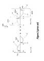
- FIG. 2depicts the periodic dimmer output voltage V DIM waveform of dimmer 102 .
- the dimmer output voltagefluctuates during each period from a positive voltage to a negative voltage.
- the positive and negative voltagesare characterized with respect to a reference to a direct current (dc) voltage level, such as a neutral or common voltage reference.
- the period of each full cycle 202 . 0 through 202 .Nis the same as 1/frequency as voltage V mains , where N is an integer.
- the dimmer 102chops the voltage half cycles 204 . 0 through 204 .N and 206 . 0 through 206 .N to alter the duty cycle of each half cycle.
- the dimmer 102chops the first half cycle 204 .
- the duty cycle of dimmer 102decreases. Between time t 2 and time t 3 , the resistance of variable resistance 106 is increased, and, thus, dimmer 102 chops the full cycle 202 .N at later times in the first half cycle 204 .N and the second half cycle 206 .N of the full cycle 202 .N with respect to cycle 202 . 0 . Dimmer 102 continues to chop the first half cycle 204 .N with the same timing as the second half cycle 206 .N. So, the duty cycles of each half cycle of cycle 202 .N are the same. Thus, the full duty cycle of dimmer 102 for cycle 202 .N is:
- conventional dimmersprovide dependently generated phase delays per cycle of a phase modulated signal.
- an apparatus to generate at least two independent signals in response to at least two independent items of information derived from at least two independently generated phase delays per cycle of a phase modulated mains voltage signalincludes a phase delay detector to detect at least two independently generated phase delays per cycle of the phase modulated mains voltage signal and to generate respective data signals. Each data signal represents an item of information conforming to one of the phase delays.
- the apparatusfurther includes a controller, coupled to the phase delay detector, to receive the data signals and, for each received data signal, to generate a control signal in conformity with the item of information represented by the data signal.
- a method to generate at least two independent signals in response to at least two independent items of information derived from at least two independently generated phase delays per cycle of a phase modulated mains voltage signalincludes detecting at least two independent phase delays per cycle of the phase modulated mains voltage signal. Each phase delay represents an independent item of information. The method further includes generating respective data signals. Each data signal represents an item of information conforming to one of the phase delays; and for each data signal. The method also includes generating a control signal in conformity with the item of information represented by the data signal.
- An apparatusincludes a dimming control to receive at least two respective inputs representing respective dimming levels and a dimming signal generator, coupled to the dimming control, to generate a phase modulated output signal having at least two independently generated phase delays per cycle of the phase modulated mains voltage signal. Each dimming level is represented by one of the phase delays.
- a methodin another embodiment, includes receiving at least two respective inputs representing respective dimming levels and independently generating at least two phase delays per cycle in a mains voltage signal to generate a phase modulated output signal. Each phase delay per cycle represents a respective dimming level.
- FIG. 1(labeled prior art) depicts a lighting circuit with a conventional dimmer for dimming an incandescent light source.
- FIG. 2(labeled prior art) depicts a dimmer circuit output voltage waveform.
- FIG. 3Adepicts a duty cycle modifier
- FIG. 3Bdepicts another duty cycle modifier.
- FIG. 3Cdepicts a phase delay detector
- FIG. 3Ddepicts another phase delay detector.
- FIGS. 4A-4Ddepict a waveform with independently generated phased delays per cycle of a phase modulated signal.
- FIG. 4Edepicts a phase modulated signal with symmetric leading and trailing edges.
- FIG. 5depicts one embodiment of a dimmer for controlling two functions of a lighting circuit.
- FIG. 6depicts a lighting circuit
- FIG. 7depicts a light emitting diode (LED) lighting and power system.
- a system and methodmodify phase delays of a periodic, phase modulated mains voltage to generate at least two independent items of information during each cycle of the periodic input signal.
- the independent items of informationcan be generated by, for example, independently modifying leading edge and trailing edge phase delays of each half cycle phase modulated mains voltage. Modifying phase delays for the leading and trailing edges of each half cycle of the phase modulated mains voltage can generate up to four independent items of data.
- the items of datacan be converted into independent control signals to, for example, control drive currents to respective output devices such as light sources.
- a dimmergenerates the phase delays of the mains voltage to generate the phase modulated mains voltage.
- the phase delayscan be converted into current drive signals to independently control the intensity of at least two different sets of lights, such as respective sets of light emitting diodes (LEDs).
- LEDslight emitting diodes
- FIG. 3Adepicts a phase modulator 300 that chops the leading and/or trailing edges of the positive and/or negative half cycle of AC mains voltage V mains to generate a phase modulated output signal V ⁇ .
- the mains voltage V mainsis generally supplied by a power station or other AC voltage source.
- the mains voltage V mainsis typically 120 V AC with a typical frequency of 60 Hz or 230 V AC with a typical frequency of 50 Hz.
- Each cycle of mains voltage V mainshas a first half cycle and a second half cycle. In at least one embodiment, the two half cycles are respectively referred to as a positive half cycle and a negative half cycle. “Positive” and “negative” reflect the relationship between the cycle halves and do not necessarily reflect positive and negative voltages.
- the phase modulator 300generates between 2 to 4 phase delays for each full cycle of the phase mains voltage V ⁇ . At least two of the phase delays per cycle are independently generated. An independently generated phase delay represents a separate item of information from any other phase delay in the same cycle. A dependently generated phase delay redundantly represents an item of information represented by another phase delay in the same cycle, either in the same half cycle or a different half cycle.
- phase delaysare divided into four categories. Positive half cycle leading edge phase delays and trailing edge phase delays represent two of the categories, and negative half cycle leading edge and trailing edge phase delays represent two additional categories.
- the positive half cycle phase delaysoccur in the positive half cycle, and the negative half cycle phase delays occur in the negative half cycle.
- the leading edge phase delaysrepresent the elapsed time between a beginning of a half cycle and a leading edge of the phase modulated mains voltage V ⁇ .
- the trailing edge phase delaysrepresent the elapsed time between a trailing edge of the phase modulated mains voltage V ⁇ and the end of a half cycle. Phase delays may be dependently or independently generated.
- the half cyclesare separated by the zero crossings of the original, undimmed mains voltage V mains .
- the phase delay of the first half cycle of phase modulated output signal V ⁇is controlled by the value selectable current I 1 .
- diode 302conducts current I 1 , and current I 1 charges capacitor 110 .
- capacitor 110charges to a voltage greater than a trigger voltage of diac 114
- the diac 114conducts and the gate of triac 116 charges.
- the resulting voltage at the gate of triac 116 and across bias resistor 118causes the triac 116 to conduct until current I 1 falls to zero at the end of the first half cycle of mains voltage V mains .
- the elapsed time between the beginning of the half cycle and when the triac 116 begins to conductrepresents a leading edge phase delay.
- the phase modulated output signal V ⁇is 0 V.
- the output voltage V OUTequals the mains voltage V mains .
- the conduction time of triac 116 during the first half cycle of mains voltage V mainsis directly related to the charge time of capacitor 110 and is, thus, directly related to the value of current I 1 .
- the conduction time of triac 116 during the first half cycle of mains voltage V mainsdirectly controls a leading edge phase delay of the first half cycle of output voltage V OUT .
- the value of current I 1directly corresponds to the phase delay of the first half cycle of phase modulated output signal V m .
- the resistor 112 and variable resistor 304control the value of current I 1 during each first half cycle of mains voltage V mains .
- the value of current I 1is selectable by changing the resistance of variable resistor 304 . Therefore, varying selectable current I 1 varies the leading edge phase delay of the first half cycle of phase modulated output signal V ⁇ .
- the leading edge phase delay of the negative cycle of phase modulated output signal V ⁇is controlled by selectable current I 2 .
- diode 306conducts current I 2 , and current I 2 charges capacitor 110 .
- capacitor 110charges to a voltage greater than a trigger voltage of diac 114
- the diac 114conducts and the gate of triac 116 charges.
- the resulting voltage at the gate of triac 116 and across bias resistor 118causes the triac 116 to conduct until current I 2 falls to zero at the end of the negative cycle of mains voltage V mains .
- triac 116begins to conduct, a leading edge of the second half cycle of phase modulated output signal V ⁇ is generated.
- the elapsed time between the beginning of the second half cycle and the leading edge of the second half cyclerepresents a leading edge phase delay of the second half cycle.
- the conduction time of triac 116 during the second half cycle of mains voltage V mainsis directly related to the charge time of capacitor 110 and is, thus, directly related to the value of current I 2 .
- the conduction time of triac 116 during the second half cycle of mains voltage V mainsdirectly controls the leading edge phase delay of the second half cycle of phase modulated output signal V ⁇ .
- the value of current I 2directly corresponds to the leading edge phase delay of the second half cycle of phase modulated output signal V ⁇ .
- variable resistor 304is set by input A.
- the resistance value of variable resistor 306is set by input B.
- variable resistor 304is a potentiometer with a mechanical wiper. The resistance of variable resistor 304 changes with physical movement of the wiper.
- variable resistor 304is implemented using semiconductor devices to provide a selectable resistance.
- the input Ais a control signal received from a controller.
- the controllerset input A in response to an input, such as a physical button depression sequence, a value received from a remote control device, and/or a value received from a timer or motion detector.
- the source or sources of input Acan be manual or any device capable of modifying the resistance of variable resistor 304 .
- variable resistor 306is the same as variable resistor 304 .
- the source of input Bcan be manual or any device capable of modifying the resistance of variable resistor 306 .
- the output voltage V OUTis provided as an input to phase delay detector 310 .
- Phase delay detector 310detects the phase delays of phase modulated output signal V ⁇ and generates a digital dimmer output signal value D V.X for each independently generated phase delay per cycle.
- Xis an integer index value ranging from 0 to M, and M+1 represents the number of independently generated phase delays per cycle of phase modulated output signal V ⁇ .
- Mranges from 1 to 3.
- Dimmer signals D V.0 , . . . , D V.Mare collectively represented by “D V ”.
- the values of digital dimmer output signals D vcan be used to generate control signals and drive currents.
- FIG. 3Bdepicts a phase modulator 350 that independently or dependently modifies the leading edge (LE) and/or trailing edges (TE) of mains voltage V mains to generate 2 to 4 phase delays representing 2 to 4 items of information per cycle of phase modulated output signal V ⁇
- the number of independent phase delays generate by phase modulator 350is a matter of design choice.
- the phase modulator 300represents one embodiment of the phase modulator 350 .
- the first half cycle phase delay generator 352generates phase delays in the first half cycle of input signal V mains by chopping the mains voltage V mains to generate a leading edge, trailing edge, or both the leading and trailing edges of phase modulated output signal V ⁇ .
- the second half cycle phase delay generator 354generates phase delays in the second half cycle of input signal V mains by chopping the mains voltage V mains to generate a leading edge, trailing edge, or both the leading and trailing edges of phase modulated output signal V ⁇ .
- phase modulator 350two to four independent items of data are generated per each cycle of the input signal V mains .
- the input mains voltage V mainscan be chopped to generate both leading and trailing edges as for example described in U.S. Pat. No. 6,713,974, entitled “Lamp Transformer For Use With An Electronic Dimmer And Method For Use Thereof For Reducing Acoustic Noise”, inventors Patchornik and Barak.
- U.S. Pat. No. 6,713,974describes an exemplary system and method for leading and trailing edge voltage chopping and edge detection.
- U.S. Pat. No. 6,713,974is incorporated herein by reference in its entirety.
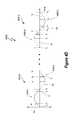
- FIGS. 4A , 4 B, 4 C, and 4 Ddepict exemplary respective waveforms 400 A, 400 B, 400 C, and 400 D of phase modulated output signal V ⁇ .
- the waveforms 400 A, 400 B, 400 C, and 400 Drepresent cycles of a phase modulated mains voltage V ⁇ .
- the waveforms 400 A, 400 B, 400 C, and 400 Deach include between 2 and 4 independently generated phase delays per cycle. Leading edge phase delays are represented by “a” (alpha), and trailing edge delays are represented by “(3” (beta).
- FIG. 4Adepicts leading and trailing edge phase delays of two exemplary cycles 402 A. 0 and 402 A.N of the waveform 400 A of phase modulated output signal V ⁇ .
- Each cycle of leading edge phase delays al generated in the first and second half cycles 404 A. 0 and 406 A. 0respectively, independently of the trailing edge phase delays ⁇ 1 of the first and second half cycles 404 A. 0 and 406 A. 0 .
- the second half cyclerepeats the first half cycle, so the two leading edge phase delays are not independent, and the two trailing edge phase delays are also not independent.
- the leading edge phase delaysrepresent the elapsed time between a beginning of a half cycle and a leading edge of the phase modulated mains voltage V ⁇ .
- the trailing edge phase delaysrepresent the elapsed time between a trailing edge of the phase modulated mains voltage V ⁇ and the end of a half cycle.
- An exemplary determination of the phase delays for waveform 400 Ais set forth below.
- the phase delays for waveforms 400 B- 400 Dare similarly determined and subsequently set forth in Table 2.
- the phase modulator 350generates new leading edge phase delays al and trailing edge phase delays ⁇ 1 for cycle 402 A.N.
- the leading edges phase delays al of the first and second half cycles 404 A.N and 406 A.Nare not generated independently of each other but are generated independently of trailing edge phase delays ⁇ 1 .
- the trailing edges phase delays ⁇ 1 of the first and second half cycles 404 A.N and 406 A.Nare not generated independently of each other but are generated independently of leading edge phase delays ⁇ 1 . Accordingly, the phase delays of each cycle of waveform 400 A represent two items of information.
- waveform 400 Ais generated with identical leading edge phase delays for the first and second half cycles of each cycle of phase modulated output signal V ⁇ and identical trailing edge phase delays for the first and second half cycles of each cycle of phase modulated output signal V ⁇ because the symmetry between the first half cycle 404 A.X and the second half cycle 406 A.X facilitates keeping dimmer output signals D V free of DC signals. In an application with a large current drain due to lighting equipment, in at least one embodiment, it is also desirable to protect a mains transformer (not shown) from excessive DC current. In at least one embodiment, waveforms such as waveform 400 A, that have first half cycles with approximately the same area as second half cycles facilitate keeping dimmer output signals D V free of DC signals.
- FIG. 4Bdepicts independently generated leading edge phase delays of two exemplary cycles 402 B. 0 and 402 B.N of the waveform 400 B of phase modulated output signal V ⁇ .
- Full cycle 402 B. 0is composed of first half cycle 404 B. 0 and second half cycle 406 B. 0 .
- Full cycle 402 B.Nis composed of first half cycle 404 B.N and second half cycle 406 B.N.
- Waveform 400 Bdepicts the independent generation of a first half cycle leading edge phase delay al and a second half cycle leading edge phase delay ⁇ 2 .
- FIG. 4Cdepicts independently generated trailing edge phase delays of two exemplary cycles 402 C. 0 and 402 C.N of the waveform 400 C of phase modulated output signal V ⁇ .
- Full cycle 402 C. 0is composed of first half cycle 404 C. 0 and second half cycle 406 C. 0 .
- Full cycle 402 C.Nis composed of first half cycle 404 C.N and second half cycle 406 C.N.
- Waveform 400 Cdepicts the independent generation of a first half cycle trailing edge phase delay ⁇ 1 and a second half cycle trailing edge phase delay ⁇ 2 .
- FIG. 4Ddepicts independently generated leading edges and trailing edges for both half cycles of two exemplary cycles 402 D. 0 and 402 D.N of the waveform 400 D of phase modulated output signal V ⁇ .
- Full cycle 402 D. 0is composed of first half cycle 404 D. 0 and second half cycle 406 D. 0 .
- Full cycle 402 D.Nis composed of first half cycle 404 D.N and second half cycle 406 D.N.
- Waveform 400 Ddepicts the independent generation of a first half cycle leading edge phase delay ⁇ 1 , a first half cycle trailing edge phase delay ⁇ 1 , a second half cycle leading edge phase delay ⁇ 2 , and a second half cycle trailing edge phase delay ⁇ 2 .
- Table 1sets forth the phase delays and corresponding time values of waveforms 400 A- 400 D:
- the independent phase delays of the first half cycle and the second half cycle of each waveform of phase modulated output signal V ⁇represent independent items of information.
- the waveforms 400 A, 400 B, and 400 Ceach have two independent items of information per cycle of phase modulated output signal V ⁇ .
- the waveform 400 Dhas four independent items of information per cycle of phase modulated output signal V ⁇ .
- Table 2depicts the independent items of information available from the phase delays for each cycle of each depicted waveform of phase modulated output signal
- FIG. 4Edepicts a waveform 400 E representing an exemplary phase modulated output signal V ⁇ with four dependent phase delays per cycle but only one item of information per cycle.
- the two depicted cycles 402 E. 0 and 402 E.Neach have respective half cycles 404 E. 0 & 406 E. 0 and 404 E.N & 406 E.N.
- the leading and trailing edges of each half cyclehave a phase delay of al.
- the waveform 400 Eonly includes one independent phase delay al
- the symmetry of the leading and trailing edges of each cycle of waveform 400 Emake detection of the phase delay al relatively easy compared to detection of leading edge only or trailing edge only phase delays.
- the symmetry of waveform 400 Efacilitates keeping dimmer output signal D V free of DC signals.
- the individual items of information from each cyclecan be detected, converted into data, such as digital data, and used to generate respective control signals.
- the control signalscan, for example, be converted into separate current drive signals for light sources in a lighting device and/or used to implement predetermined functions, such as actuating predetermined dimming levels in response to a particular dimming level or in response to a period of inactivity of a dimmer, etc.
- FIG. 3Cdepicts a phase delay detector 320 to determine phase delays of leading and trailing edges of phase modulated output signal V ⁇ .
- Phase delay detector 320represents one embodiment of phase delay detector 356 .
- Comparator 322compares phase modulated output signal V ⁇ against a known reference. The reference is generally the cycle cross-over point voltage of phase modulated output signal V ⁇ , such as a neutral potential of a household AC voltage.
- the counter 324counts the number of cycles of clock signal f clk that occur until the comparator 322 indicates that an edge of phase modulated output signal V ⁇ has been reached.
- a leading edge phase delaycan be determined from the count of cycles of clock signal f clk that occur from the beginning of a half cycle until the comparator 322 indicates the leading edge of phase modulated output signal V ⁇ .
- the trailing edge of each half cyclecan be determined from the count of cycles of clock signal f clk that occur from a trailing edge until an end of a half cycle of phase modulated output signal V ⁇ .
- the counter 324converts the phase delays into digital dimmer output signal values D V for each cycle of phase modulated output signal V ⁇ .
- FIG. 3Ddepicts a phase delay detector 360 .
- Phase delay detector 360represents one embodiment of phase delay detector 356 in FIG. 3B .
- the phase delay detector 360includes an analog integrator 362 that integrates dimmer output signal V DIM during each cycle (full or half cycle) of phase modulated output signal V ⁇ .
- the analog integrator 362generates a current I corresponding to the duty cycle of phase modulated output signal V ⁇ for each cycle of phase modulated output signal V ⁇ .
- the current provided by the analog integrator 362charges a capacitor 368 to threshold voltage V C , and the voltage V C across capacitor 368 can be determined by analog-to-digital converter (ADC) 364 .
- ADCanalog-to-digital converter
- the analog integrator 362can be reset after each cycle of phase modulated output signal V ⁇ by discharging capacitors 366 and 368 .
- Switch 370includes a control terminal to receive reset signal S R .
- Switch 372includes a control terminal to receive sample signal S S .
- the charge on capacitor 368is sampled by capacitor 366 when control signal S S causes switch 372 to conduct.
- reset signal S Ropens switch 370 to discharge and, thus, reset capacitor 368 .
- switches 370 and 372are n-channel field effect transistors, and sample signal S S and reset signal S R have non-overlapping pulses.
- each cycle of dimmer output signal V DIMcan be detected by every other zero crossing of dimmer output signal V DIM .
- FIG. 5depicts one embodiment of a dimmer 500 for controlling two functions of a lighting circuit, such as lighting circuit 600 ( FIG. 6 ).
- dimmer 500represents one embodiment of the phase modulator 300
- dimmer 500represents one embodiment of the phase modulator 350 .
- the dimmerincludes two slideable switches 502 and 504 .
- moving switch 502vertically provides an input A, which selects the value of selectable current I 1 by varying the resistance of variable resistor 304 .
- moving switch 504horizontally provides an input B, which selects the value of selectable current I 2 by varying the resistance of variable resistor 306 .
- switches 502 and 504control the phase delays of respective positive and second half cycles of phase modulated output signal V ⁇ ( FIG. 3 ).
- FIG. 6depicts an exemplary lighting circuit 600 .
- the lighting circuit 600represents one embodiment of a load for phase modulator 300 .
- the lighting circuit 600includes a LED Controller/Driver circuit 602 that responds to digital data D V .
- the items of information derived from phase delays of phase modulated output signal V ⁇ and represented by the digital data D Vcan be converted into respective control signals for controlling, for example, the drive currents to LED bank 604 .
- LED bank 604includes one or more LEDs 608 . 0 through 608 .M, where M is a positive integer.
- LED bank 606includes one or more LEDs 610 . 0 through 610 .K, where K is a positive integer.
- the LED Controller/Driver circuit 602provides drive currents I D1 and I D2 to respective LED banks 604 and 606 to control the intensity of each LED in LED banks 604 and 606 .
- the average values of the drive currents I D1 and I D2directly correspond to the respective phase delays of the first and second half cycles of phase modulated output signal V ⁇ .
- the intensity of LED banks 604 and 606can be varied independently.
- the LED banks 604 and 606contain different colored LEDs. Thus, varying the intensity of LED banks 604 and 606 also varies the blended colors produced by LED banks 604 and 606 .
- LED Controller/Driver circuit 602Exemplary embodiments of LED Controller/Driver circuit 602 are described in Melanson I, Melanson II, Melanson V, and Melanson VII.
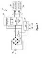
- FIG. 7depicts a light emitting diode (LED) lighting and power system 700 .
- the lighting and power system 700utilizes phase delays of a phase modulated output signal V ⁇ to generate independently determined LED drive currents.
- a full diode bridge 702rectifies the AC mains voltage V mains .
- the dim controller 704receives leading edge LE and trailing edge TE phase delay inputs.
- the leading edge LE and trailing edge TE inputsrepresent signals specifying the leading edge and trailing edge phase delays of each half cycle of phase modulated output signal V ⁇ in accordance with waveform 400 A.
- dim controller 704receives inputs to generate phase delays in accordance with waveforms 400 B, 400 C, 400 D, or 400 E.
- the dim controller 704generates a chopping control signals SC.
- the chopping control signal SCcauses switch 706 to switch ON and OFF, where “ON” is conductive and “OFF” is nonconductive.
- switch 706is ON, the phase modulated output signal V ⁇ equals zero, and when switch 706 is OFF, phase modulated output signal V ⁇ equals V mains .
- dim controller 704generates a leading edge phase delay when switch 706 transitions from ON to OFF and generates a trailing edge phase delay when switch 706 transitions from OFF to ON.
- the phase delay detector 708detects the phase delays of phase modulated output signal V ⁇ and generates respective digital data dimmer signals D V1 and D V2 .
- the phase delay detector 708can be any phase delay detector, such as phase delay detector 320 or phase delay detector 360 .
- the digital data dimmer signals D v1 and D v2represent respective items of information derived from the phase delays of each cycle of phase modulated output signal V ⁇ as, for example, set forth in Table 2.
- the digital data dimmer signals D V1 and D V2are mapped to respective dimming levels in accordance with Melanson III.
- the LED controller/driver 602converts the digital data dimmer signals D V1 and D v2 into respective control signals I D1 and I D2 .
- control signals I D1 and I D2are LED drive currents I D1 and I D2 .
- LED controller/driver 602generates LED drive currents I D1 and I D2 in accordance with Melanson IV.
- LED controller/driver 602includes a switching power converter that performs power factor correction on the phase modulated output signal V ⁇ and boosts the phase modulated output signal V ⁇ to an approximately constant output voltage as, for example, described in Melanson V and Melanson VI.
- the LED drive currents I D1 and I D2provide current to respective switching LED systems 604 and 606 .
- the switching LED systems 604 and 606each include one or more LEDs.
- the control signals I D1 and I D2cause each switching LED systems 604 and 606 to operate independently.
- the control signals I D1 and I D2are both connected to each of switching LED systems 604 and 606 (as indicated by the dashed lines) and cause each switching LED systems 604 and 606 to operate in unison with two different functions.
- control signal I D1can adjust the brightness of both switching LED systems 604 and 606
- control signal I D2can adjust a color temperature of both switching LED systems 604 and 606
- the phase modulator 300generates a phase modulated output signal with 2 to 4 independent phase delays for each cycle of the phase modulated output signal.
- Each independent phase delay per cyclerepresents an independent item of information.
- detected, independent phase delayscan be converted into independent control signals.
- the control signalscan be used to control drive currents to respective circuits, such as respective sets of light emitting diodes.
Landscapes
- Circuit Arrangement For Electric Light Sources In General (AREA)
Abstract
Description
| TABLE 1 | |
| Cycles & Half Cycles | Phase Delay |
| 402A.0 | α1 = (t1− t0) = (t4− t3) |
| 402A.0 | β1 = (t3− t2) = (t6− t5) |
| 402A.N | α1 = (t8− t7) = (t6− t10) |
| 402A.N | β1 = (t10− t9) = (t13− t12) |
| 402B.0 | α1 = (t1− t0) |
| 402B.0 | α2 = (t3− t2) |
| 402B.N | α1 = (t6− t5) |
| 402B.N | α2 = (t8− t7) |
| 402C.0 | β1 = (t2− t1) |
| 402C.0 | β2 = (t4− t3) |
| 402C.N | β1 = (t7− t6) |
| 402C.N | β2 = (t9− t8) |
| 404D.0 | α1 = (t1− t0) |
| 404D.0 | β1 = (t3− t2) |
| 406D.0 | α2 = (t4− t3) |
| 406D.0 | β2 = (t6− t5) |
| 404D.N | α1 = (t7− t8) |
| 404D.N | β1 = (t10− t9) |
| 406D.N | α2 = (t11− t10) |
| 406D.N | β2 = (t13− t12) |
| TABLE 2 | |||
| Information | |||
| 400A | α1, β1 | ||
| 400B | α1, α2 | ||
| 400C | β1, β2 | ||
| 400D | α1, β1, α2, β2 | ||
Claims (16)
Priority Applications (2)
| Application Number | Priority Date | Filing Date | Title |
|---|---|---|---|
| US12/047,258US8018171B1 (en) | 2007-03-12 | 2008-03-12 | Multi-function duty cycle modifier |
| US13/206,212US8188677B2 (en) | 2007-03-12 | 2011-08-09 | Multi-function duty cycle modifier |
Applications Claiming Priority (3)
| Application Number | Priority Date | Filing Date | Title |
|---|---|---|---|
| US89429507P | 2007-03-12 | 2007-03-12 | |
| US90945707P | 2007-04-01 | 2007-04-01 | |
| US12/047,258US8018171B1 (en) | 2007-03-12 | 2008-03-12 | Multi-function duty cycle modifier |
Related Child Applications (1)
| Application Number | Title | Priority Date | Filing Date |
|---|---|---|---|
| US13/206,212DivisionUS8188677B2 (en) | 2007-03-12 | 2011-08-09 | Multi-function duty cycle modifier |
Publications (1)
| Publication Number | Publication Date |
|---|---|
| US8018171B1true US8018171B1 (en) | 2011-09-13 |
Family
ID=44544769
Family Applications (2)
| Application Number | Title | Priority Date | Filing Date |
|---|---|---|---|
| US12/047,258Expired - Fee RelatedUS8018171B1 (en) | 2007-03-12 | 2008-03-12 | Multi-function duty cycle modifier |
| US13/206,212Expired - Fee RelatedUS8188677B2 (en) | 2007-03-12 | 2011-08-09 | Multi-function duty cycle modifier |
Family Applications After (1)
| Application Number | Title | Priority Date | Filing Date |
|---|---|---|---|
| US13/206,212Expired - Fee RelatedUS8188677B2 (en) | 2007-03-12 | 2011-08-09 | Multi-function duty cycle modifier |
Country Status (1)
| Country | Link |
|---|---|
| US (2) | US8018171B1 (en) |
Cited By (49)
| Publication number | Priority date | Publication date | Assignee | Title |
|---|---|---|---|---|
| US20100060204A1 (en)* | 2008-09-10 | 2010-03-11 | Toshiba Lighting & Technology Corporation | Power supply unit having dimmer function and lighting unit |
| US20100213870A1 (en)* | 2007-10-22 | 2010-08-26 | Nxp B.V. | Dimmer jitter correction |
| US20100270935A1 (en)* | 2009-04-24 | 2010-10-28 | Toshiba Lighting & Technology Corporation | Light-emitting device and illumination apparatus |
| US20100289426A1 (en)* | 2009-05-12 | 2010-11-18 | Toshiba Lighting & Technology Corporation | Illumination device |
| US20110043121A1 (en)* | 2009-08-21 | 2011-02-24 | Toshiba Lighting & Technology Corporation | Lighting circuit and illumination device |
| US20110057564A1 (en)* | 2009-09-04 | 2011-03-10 | Toshiba Lighting & Technology Corporation | Led lighting device and illumination apparatus |
| US20110057576A1 (en)* | 2008-03-24 | 2011-03-10 | Hirokazu Otake | Power supply device and lighting equipment |
| US20110057578A1 (en)* | 2009-09-04 | 2011-03-10 | Toshiba Lighting & Technology Corporation | Led lighting device and illumination apparatus |
| US20110057577A1 (en)* | 2008-03-24 | 2011-03-10 | Hirokazu Otake | Power supply device and lighting equipment provided with power supply device |
| US20110068706A1 (en)* | 2009-09-18 | 2011-03-24 | Toshiba Lighting & Technology Corporation | Led lighting device and illumination apparatus |
| US20110241566A1 (en)* | 2010-04-06 | 2011-10-06 | Osram Gesellschaft Mit Beschraenkter Haftung | Power supply device for light sources, such as halogen lamps, and related method |
| US20120019158A1 (en)* | 2010-07-22 | 2012-01-26 | Chiccony Power Technology Co., Ltd. | Polarity-reversible dimming controller having function of switching light source |
| US20120243213A1 (en)* | 2011-03-25 | 2012-09-27 | Chi Gon Chen | Outdoor led light fixture with dimmer switch |
| US20120299501A1 (en)* | 2008-07-25 | 2012-11-29 | Kost Michael A | Switching Power Converter Control With Triac-Based Leading Edge Dimmer Compatibility |
| US20130043801A1 (en)* | 2011-08-19 | 2013-02-21 | Chao-Li Kuwu | Lighting device |
| US20130057180A1 (en)* | 2010-05-17 | 2013-03-07 | Koninklijke Philips Electronics, N.V. | Method and apparatus for detecting and correcting improper dimmer operatioin |
| US20130169172A1 (en)* | 2011-12-28 | 2013-07-04 | Iwatt Inc, | Predictive Control of Power Converter for LED Driver |
| US20130169183A1 (en)* | 2012-01-02 | 2013-07-04 | Lextar Electronics Corporation | Illumination control circuit and illumination control method |
| AT13365U1 (en)* | 2012-04-13 | 2013-11-15 | Tridonic Gmbh & Co Kg | Control of lamps by means of defined manipulation of the supply voltage |
| US20140042924A1 (en)* | 2012-08-08 | 2014-02-13 | Leadtrend Technology Corp. | Circuit with adjustable phase delay and a feedback voltage and method for adjusting phase delay and a feedback voltage |
| WO2013158134A3 (en)* | 2012-04-18 | 2014-02-27 | Ney-Li Funding, Llc | Sensing and control for improving switched ac/dc power supplies |
| WO2014035630A1 (en) | 2012-08-27 | 2014-03-06 | Cirrus Logic, Inc. | Power conversion with controlled capacitance charging including attach state control |
| CN103687250A (en)* | 2014-01-06 | 2014-03-26 | 吴建堂 | Alternating-current (AC) LED (Light Emitting Diode) energy-saving delay lamp |
| CN103687161A (en)* | 2012-09-26 | 2014-03-26 | 深圳市海洋王照明工程有限公司 | Delay energy-saving lamp circuit and lamp |
| US20140219663A1 (en)* | 2011-09-30 | 2014-08-07 | Richard D. Roberts | Methods and arrangements for frequency shift communications |
| WO2014137565A1 (en)* | 2013-03-08 | 2014-09-12 | Dolby Laboratories Licensing Corporation | Techniques for dual modulation display with light conversion |
| US8907590B1 (en)* | 2011-05-27 | 2014-12-09 | Maxim Integrated Products, Inc. | Self-adjusted LED illumination system |
| US20150312981A1 (en)* | 2013-01-22 | 2015-10-29 | Shenzhen China Star Optoelectronics Technology Co., Ltd. | Current adjusting device and adjustment method thereof |
| US9313840B2 (en) | 2011-06-03 | 2016-04-12 | Cirrus Logic, Inc. | Control data determination from primary-side sensing of a secondary-side voltage in a switching power converter |
| WO2016084052A1 (en)* | 2014-11-29 | 2016-06-02 | Xsi Semiconductors Pvt Ltd | Dynamic bleed system and method for dynamic loading of a dimmer using event driven architecture |
| US20160183340A1 (en)* | 2013-08-02 | 2016-06-23 | Lecore Technologies Inc. | Led driving integrated circuit and driving method therefor |
| US9510401B1 (en) | 2010-08-24 | 2016-11-29 | Cirrus Logic, Inc. | Reduced standby power in an electronic power control system |
| US9710863B2 (en) | 2013-04-19 | 2017-07-18 | Strategic Patent Management, Llc | Method and apparatus for optimizing self-power consumption of a controller-based device |
| US9867241B2 (en)* | 2016-02-02 | 2018-01-09 | Lextar Electronics Corporation | Dimming module and solid state lighting device |
| US9867248B2 (en)* | 2016-01-21 | 2018-01-09 | Lextar Electronics Corporation | Dimming module, solid state lighting device, and dimming method |
| US10349482B2 (en) | 2014-11-29 | 2019-07-09 | Globalfoundries Inc. | System and method to regulate primary side current using an event driven architecture in LED circuit |
| US10448469B2 (en) | 2014-07-08 | 2019-10-15 | On-Bright Electronics (Shanghai) Co., Ltd. | Systems and methods for intelligent dimming control using TRIAC dimmers |
| US10448470B2 (en) | 2012-11-12 | 2019-10-15 | On-Bright Electronics (Shanghai) Co., Ltd. | Systems and methods for dimming control using triac dimmers |
| US10512131B2 (en)* | 2017-09-14 | 2019-12-17 | On-Bright Electronics (Shanghai) Co., Ltd. | Systems and methods for bleeder control related to lighting emitting diodes |
| US10785837B2 (en) | 2017-11-30 | 2020-09-22 | On-Bright Electronics (Shanghai) Co., Ltd. | Systems and methods for stage-based control related to TRIAC dimmers |
| US10827588B2 (en) | 2017-12-28 | 2020-11-03 | On-Bright Electronics (Shanghai) Co., Ltd. | LED lighting systems with TRIAC dimmers and methods thereof |
| US11183996B2 (en) | 2017-07-10 | 2021-11-23 | On-Bright Electronics (Shanghai) Co., Ltd. | Switch control systems for light emitting diodes and methods thereof |
| US11212885B2 (en) | 2014-04-25 | 2021-12-28 | Guangzhou On-Bright Electronics Co., Ltd. | Systems and methods for intelligent control related to TRIAC dimmers |
| US11224105B2 (en) | 2019-02-19 | 2022-01-11 | On-Bright Electronics (Shanghai) Co., Ltd. | Systems and methods with TRIAC dimmers for voltage conversion related to light emitting diodes |
| US11252799B2 (en) | 2019-12-27 | 2022-02-15 | On-Bright Electronics (Shanghai) Co., Ltd. | Systems and methods for controlling currents flowing through light emitting diodes |
| US11297704B2 (en) | 2019-08-06 | 2022-04-05 | On-Bright Electronics (Shanghai) Co., Ltd. | Systems and methods for bleeder control related to TRIAC dimmers associated with LED lighting |
| US11405992B2 (en) | 2019-11-20 | 2022-08-02 | On-Bright Electronics (Shanghai) Co., Ltd. | Systems and methods for dimming control related to TRIAC dimmers associated with LED lighting |
| US11540371B2 (en) | 2020-04-13 | 2022-12-27 | On-Bright Electronics (Shanghai) Co., Ltd. | Systems and methods for controlling power factors of LED lighting systems |
| US11564299B2 (en) | 2019-12-19 | 2023-01-24 | On-Bright Electronics (Shanghai) Co., Ltd. | Systems and methods for providing power supply to current controllers associated with LED lighting |
Families Citing this family (5)
| Publication number | Priority date | Publication date | Assignee | Title |
|---|---|---|---|---|
| EP2305007B1 (en)* | 2008-07-08 | 2012-12-12 | Koninklijke Philips Electronics N.V. | Methods and apparatus for determining relative positions of led lighting units |
| US8314571B2 (en)* | 2010-12-14 | 2012-11-20 | Greenwave Reality, Pte, Ltd. | Light with changeable color temperature |
| US8471501B2 (en)* | 2011-02-22 | 2013-06-25 | Solomon Systech Limited | Illumination brightness control apparatus and method |
| EP2608637B1 (en)* | 2011-12-21 | 2018-11-14 | Silergy Corp. | Leading-edge phase-cut bleeder control |
| US9812863B2 (en)* | 2014-12-18 | 2017-11-07 | Solantro Semiconductor Corp. | Distributed electrical microgrid control |
Citations (192)
| Publication number | Priority date | Publication date | Assignee | Title |
|---|---|---|---|---|
| US3790878A (en) | 1971-12-22 | 1974-02-05 | Keithley Instruments | Switching regulator having improved control circuiting |
| US3881167A (en) | 1973-07-05 | 1975-04-29 | Pelton Company Inc | Method and apparatus to maintain constant phase between reference and output signals |
| US4075701A (en) | 1975-02-12 | 1978-02-21 | Messerschmitt-Bolkow-Blohm Gesellschaft Mit Beschrankter Haftung | Method and circuit arrangement for adapting the measuring range of a measuring device operating with delta modulation in a navigation system |
| US4334250A (en) | 1978-03-16 | 1982-06-08 | Tektronix, Inc. | MFM data encoder with write precompensation |
| US4414493A (en) | 1981-10-06 | 1983-11-08 | Thomas Industries Inc. | Light dimmer for solid state ballast |
| US4476706A (en) | 1982-01-18 | 1984-10-16 | Delphian Partners | Remote calibration system |
| US4677366A (en) | 1986-05-12 | 1987-06-30 | Pioneer Research, Inc. | Unity power factor power supply |
| US4683529A (en) | 1986-11-12 | 1987-07-28 | Zytec Corporation | Switching power supply with automatic power factor correction |
| US4700188A (en) | 1985-01-29 | 1987-10-13 | Micronic Interface Technologies | Electric power measurement system and hall effect based electric power meter for use therein |
| US4737658A (en) | 1985-08-05 | 1988-04-12 | Brown, Boveri & Cie Ag | Centralized control receiver |
| US4797633A (en) | 1987-03-20 | 1989-01-10 | Video Sound, Inc. | Audio amplifier |
| US4937728A (en) | 1989-03-07 | 1990-06-26 | Rca Licensing Corporation | Switch-mode power supply with burst mode standby operation |
| US4940929A (en) | 1989-06-23 | 1990-07-10 | Apollo Computer, Inc. | AC to DC converter with unity power factor |
| US4973919A (en) | 1989-03-23 | 1990-11-27 | Doble Engineering Company | Amplifying with directly coupled, cascaded amplifiers |
| US4979087A (en) | 1988-09-09 | 1990-12-18 | Aviation Limited | Inductive coupler |
| US4980898A (en) | 1989-08-08 | 1990-12-25 | Siemens-Pacesetter, Inc. | Self-oscillating burst mode transmitter with integral number of periods |
| US4992919A (en) | 1989-12-29 | 1991-02-12 | Lee Chu Quon | Parallel resonant converter with zero voltage switching |
| US4994952A (en) | 1988-02-10 | 1991-02-19 | Electronics Research Group, Inc. | Low-noise switching power supply having variable reluctance transformer |
| US5001620A (en) | 1988-07-25 | 1991-03-19 | Astec International Limited | Power factor improvement |
| US5109185A (en) | 1989-09-29 | 1992-04-28 | Ball Newton E | Phase-controlled reversible power converter presenting a controllable counter emf to a source of an impressed voltage |
| US5121079A (en) | 1991-02-12 | 1992-06-09 | Dargatz Marvin R | Driven-common electronic amplifier |
| US5206540A (en) | 1991-05-09 | 1993-04-27 | Unitrode Corporation | Transformer isolated drive circuit |
| US5264780A (en) | 1992-08-10 | 1993-11-23 | International Business Machines Corporation | On time control and gain circuit |
| US5278490A (en) | 1990-09-04 | 1994-01-11 | California Institute Of Technology | One-cycle controlled switching circuit |
| EP0585789A1 (en) | 1992-09-01 | 1994-03-09 | Power Integrations, Inc. | Three-terminal switched mode power supply integrated circuit |
| US5323157A (en) | 1993-01-15 | 1994-06-21 | Motorola, Inc. | Sigma-delta digital-to-analog converter with reduced noise |
| US5359180A (en) | 1992-10-02 | 1994-10-25 | General Electric Company | Power supply system for arcjet thrusters |
| US5383109A (en) | 1993-12-10 | 1995-01-17 | University Of Colorado | High power factor boost rectifier apparatus |
| US5424932A (en) | 1993-01-05 | 1995-06-13 | Yokogawa Electric Corporation | Multi-output switching power supply having an improved secondary output circuit |
| US5477481A (en) | 1991-02-15 | 1995-12-19 | Crystal Semiconductor Corporation | Switched-capacitor integrator with chopper stabilization performed at the sampling rate |
| US5479333A (en) | 1994-04-25 | 1995-12-26 | Chrysler Corporation | Power supply start up booster circuit |
| US5481178A (en) | 1993-03-23 | 1996-01-02 | Linear Technology Corporation | Control circuit and method for maintaining high efficiency over broad current ranges in a switching regulator circuit |
| US5565761A (en) | 1994-09-02 | 1996-10-15 | Micro Linear Corp | Synchronous switching cascade connected offline PFC-PWM combination power converter controller |
| US5589759A (en) | 1992-07-30 | 1996-12-31 | Sgs-Thomson Microelectronics S.R.L. | Circuit for detecting voltage variations in relation to a set value, for devices comprising error amplifiers |
| US5638265A (en) | 1993-08-24 | 1997-06-10 | Gabor; George | Low line harmonic AC to DC power supply |
| US5691890A (en) | 1995-12-01 | 1997-11-25 | International Business Machines Corporation | Power supply with power factor correction circuit |
| US5747977A (en) | 1995-03-30 | 1998-05-05 | Micro Linear Corporation | Switching regulator having low power mode responsive to load power consumption |
| US5757635A (en) | 1995-12-28 | 1998-05-26 | Samsung Electronics Co., Ltd. | Power factor correction circuit and circuit therefor having sense-FET and boost converter control circuit |
| US5781040A (en) | 1996-10-31 | 1998-07-14 | Hewlett-Packard Company | Transformer isolated driver for power transistor using frequency switching as the control signal |
| US5783909A (en) | 1997-01-10 | 1998-07-21 | Relume Corporation | Maintaining LED luminous intensity |
| US5798635A (en) | 1996-06-20 | 1998-08-25 | Micro Linear Corporation | One pin error amplifier and switched soft-start for an eight pin PFC-PWM combination integrated circuit converter controller |
| US5811940A (en)* | 1994-06-22 | 1998-09-22 | Physiomed-Medizintechnik Gmbh | Phase-shift lamp control |
| EP0910168A1 (en) | 1997-10-16 | 1999-04-21 | Hewlett-Packard Company | Delta-sigma pulse width modulator |
| US5900683A (en) | 1997-12-23 | 1999-05-04 | Ford Global Technologies, Inc. | Isolated gate driver for power switching device and method for carrying out same |
| US5929400A (en) | 1997-12-22 | 1999-07-27 | Otis Elevator Company | Self commissioning controller for field-oriented elevator motor/drive system |
| US5946202A (en) | 1997-01-24 | 1999-08-31 | Baker Hughes Incorporated | Boost mode power conversion |
| US5946206A (en) | 1997-02-17 | 1999-08-31 | Tdk Corporation | Plural parallel resonant switching power supplies |
| US5952849A (en) | 1997-02-21 | 1999-09-14 | Analog Devices, Inc. | Logic isolator with high transient immunity |
| US5963086A (en) | 1997-08-08 | 1999-10-05 | Velodyne Acoustics, Inc. | Class D amplifier with switching control |
| US5966297A (en) | 1997-08-28 | 1999-10-12 | Iwatsu Electric Co., Ltd. | Large bandwidth analog isolation circuit |
| US6016038A (en) | 1997-08-26 | 2000-01-18 | Color Kinetics, Inc. | Multicolored LED lighting method and apparatus |
| US6043633A (en) | 1998-06-05 | 2000-03-28 | Systel Development & Industries | Power factor correction method and apparatus |
| US6072969A (en) | 1996-03-05 | 2000-06-06 | Canon Kabushiki Kaisha | Developing cartridge |
| US6083276A (en) | 1998-06-11 | 2000-07-04 | Corel, Inc. | Creating and configuring component-based applications using a text-based descriptive attribute grammar |
| US6084450A (en) | 1997-01-14 | 2000-07-04 | The Regents Of The University Of California | PWM controller with one cycle response |
| US6181114B1 (en) | 1999-10-26 | 2001-01-30 | International Business Machines Corporation | Boost circuit which includes an additional winding for providing an auxiliary output voltage |
| US6211626B1 (en) | 1997-08-26 | 2001-04-03 | Color Kinetics, Incorporated | Illumination components |
| US6211627B1 (en) | 1997-07-29 | 2001-04-03 | Michael Callahan | Lighting systems |
| US6229271B1 (en) | 2000-02-24 | 2001-05-08 | Osram Sylvania Inc. | Low distortion line dimmer and dimming ballast |
| US6229292B1 (en) | 1999-02-12 | 2001-05-08 | Analog Devices, Inc. | Voltage regulator compensation circuit and method |
| US6246183B1 (en) | 2000-02-28 | 2001-06-12 | Litton Systems, Inc. | Dimmable electrodeless light source |
| US6259614B1 (en) | 1999-07-12 | 2001-07-10 | International Rectifier Corporation | Power factor correction control circuit |
| US6300723B1 (en) | 1998-07-29 | 2001-10-09 | Philips Electronics North America Corporation | Apparatus for power factor control |
| US6304473B1 (en) | 2000-06-02 | 2001-10-16 | Iwatt | Operating a power converter at optimal efficiency |
| US6343026B1 (en) | 2000-11-09 | 2002-01-29 | Artesyn Technologies, Inc. | Current limit circuit for interleaved converters |
| US6344811B1 (en) | 1999-03-16 | 2002-02-05 | Audio Logic, Inc. | Power supply compensation for noise shaped, digital amplifiers |
| US6385063B1 (en) | 1998-06-23 | 2002-05-07 | Siemens Aktiengesellschaft | Hybrid filter for an alternating current network |
| EP1213823A2 (en) | 2000-12-04 | 2002-06-12 | Sanken Electric Co., Ltd. | DC-to-DC converter |
| US6407691B1 (en) | 2000-10-18 | 2002-06-18 | Cirrus Logic, Inc. | Providing power, clock, and control signals as a single combined signal across an isolation barrier in an ADC |
| US6441558B1 (en) | 2000-12-07 | 2002-08-27 | Koninklijke Philips Electronics N.V. | White LED luminary light control system |
| US6445600B2 (en) | 1998-07-13 | 2002-09-03 | Ben-Gurion University Of The Negev Research & Development Authority | Modular structure of an apparatus for regulating the harmonics of current drawn from power lines by an electronic load |
| US6452521B1 (en) | 2001-03-14 | 2002-09-17 | Rosemount Inc. | Mapping a delta-sigma converter range to a sensor range |
| US20020145041A1 (en) | 2001-03-16 | 2002-10-10 | Koninklijke Philips Electronics N.V. | RGB LED based light driver using microprocessor controlled AC distributed power system |
| US20020150151A1 (en) | 1997-04-22 | 2002-10-17 | Silicon Laboratories Inc. | Digital isolation system with hybrid circuit in ADC calibration loop |
| US6469484B2 (en) | 2000-12-13 | 2002-10-22 | Semiconductor Components Industries Llc | Power supply circuit and method thereof to detect demagnitization of the power supply |
| US20020166073A1 (en) | 2001-05-02 | 2002-11-07 | Nguyen James Hung | Apparatus and method for adaptively controlling power supplied to a hot-pluggable subsystem |
| WO2002091805A2 (en) | 2001-05-10 | 2002-11-14 | Color Kinetics Incorporated | Systems and methods for synchronizing lighting effects |
| US6495964B1 (en) | 1998-12-18 | 2002-12-17 | Koninklijke Philips Electronics N.V. | LED luminaire with electrically adjusted color balance using photodetector |
| US6509913B2 (en) | 1998-04-30 | 2003-01-21 | Openwave Systems Inc. | Configurable man-machine interface |
| US20030095013A1 (en) | 2000-05-10 | 2003-05-22 | Melanson John L. | Modulation of a digital input signal using a digital signal modulator and signal splitting |
| US6583550B2 (en) | 2000-10-24 | 2003-06-24 | Toyoda Gosei Co., Ltd. | Fluorescent tube with light emitting diodes |
| US20030174520A1 (en) | 2000-10-24 | 2003-09-18 | Igor Bimbaud | Self-oscillating control circuit voltage converter |
| US6628106B1 (en) | 2001-07-30 | 2003-09-30 | University Of Central Florida | Control method and circuit to provide voltage and current regulation for multiphase DC/DC converters |
| US6636003B2 (en) | 2000-09-06 | 2003-10-21 | Spectrum Kinetics | Apparatus and method for adjusting the color temperature of white semiconduct or light emitters |
| US6646848B2 (en) | 2001-01-31 | 2003-11-11 | Matsushita Electric Industrial Co., Ltd. | Switching power supply apparatus |
| US20030223255A1 (en) | 2002-05-31 | 2003-12-04 | Green Power Technologies Ltd. | Method and apparatus for active power factor correction with minimum input current distortion |
| US20040004465A1 (en) | 2002-07-08 | 2004-01-08 | Cogency Semiconductor Inc. | Dual-output direct current voltage converter |
| US20040046683A1 (en) | 2001-03-08 | 2004-03-11 | Shindengen Electric Manufacturing Co., Ltd. | DC stabilized power supply |
| US6713974B2 (en) | 2002-01-10 | 2004-03-30 | Lightech Electronic Industries Ltd. | Lamp transformer for use with an electronic dimmer and method for use thereof for reducing acoustic noise |
| US6724174B1 (en) | 2002-09-12 | 2004-04-20 | Linear Technology Corp. | Adjustable minimum peak inductor current level for burst mode in current-mode DC-DC regulators |
| US6727832B1 (en) | 2002-11-27 | 2004-04-27 | Cirrus Logic, Inc. | Data converters with digitally filtered pulse width modulation output stages and methods and systems using the same |
| US20040085030A1 (en) | 2002-10-30 | 2004-05-06 | Benoit Laflamme | Multicolor lamp system |
| US20040085117A1 (en) | 2000-12-06 | 2004-05-06 | Joachim Melbert | Method and device for switching on and off power semiconductors, especially for the torque-variable operation of an asynchronous machine, for operating an ignition system for spark ignition engines, and switched-mode power supply |
| US6737845B2 (en) | 2001-06-21 | 2004-05-18 | Champion Microelectronic Corp. | Current inrush limiting and bleed resistor current inhibiting in a switching power converter |
| US6741123B1 (en) | 2002-12-26 | 2004-05-25 | Cirrus Logic, Inc. | Delta-sigma amplifiers with output stage supply voltage variation compensation and methods and digital amplifier systems using the same |
| US6753661B2 (en) | 2002-06-17 | 2004-06-22 | Koninklijke Philips Electronics N.V. | LED-based white-light backlighting for electronic displays |
| US6768655B1 (en) | 2003-02-03 | 2004-07-27 | System General Corp. | Discontinuous mode PFC controller having a power saving modulator and operation method thereof |
| US6781351B2 (en) | 2002-08-17 | 2004-08-24 | Supertex Inc. | AC/DC cascaded power converters having high DC conversion ratio and improved AC line harmonics |
| US20040169477A1 (en) | 2003-02-28 | 2004-09-02 | Naoki Yanai | Dimming-control lighting apparatus for incandescent electric lamp |
| US6788011B2 (en) | 1997-08-26 | 2004-09-07 | Color Kinetics, Incorporated | Multicolored LED lighting method and apparatus |
| US20040227571A1 (en) | 2003-05-12 | 2004-11-18 | Yasuji Kuribayashi | Power amplifier circuit |
| US20040228116A1 (en) | 2003-05-13 | 2004-11-18 | Carroll Miller | Electroluminescent illumination for a magnetic compass |
| US20040232971A1 (en) | 2003-03-06 | 2004-11-25 | Denso Corporation | Electrically insulated switching element drive circuit |
| US20040239262A1 (en) | 2002-05-28 | 2004-12-02 | Shigeru Ido | Electronic ballast for a discharge lamp |
| US6839247B1 (en) | 2003-07-10 | 2005-01-04 | System General Corp. | PFC-PWM controller having a power saving means |
| US6860628B2 (en) | 2002-07-17 | 2005-03-01 | Jonas J. Robertson | LED replacement for fluorescent lighting |
| US20050057237A1 (en) | 2002-01-11 | 2005-03-17 | Robert Clavel | Power factor controller |
| US6870325B2 (en) | 2002-02-22 | 2005-03-22 | Oxley Developments Company Limited | Led drive circuit and method |
| US6873065B2 (en) | 1997-10-23 | 2005-03-29 | Analog Devices, Inc. | Non-optical signal isolator |
| US20050077840A1 (en)* | 2003-10-14 | 2005-04-14 | Astral Communications, Inc. | Linear control device for controlling a resistive and/or an inductive and/or a capacitive load |
| US6882552B2 (en) | 2000-06-02 | 2005-04-19 | Iwatt, Inc. | Power converter driven by power pulse and sense pulse |
| US6888322B2 (en) | 1997-08-26 | 2005-05-03 | Color Kinetics Incorporated | Systems and methods for color changing device and enclosure |
| US6894471B2 (en) | 2002-05-31 | 2005-05-17 | St Microelectronics S.R.L. | Method of regulating the supply voltage of a load and related voltage regulator |
| US20050156770A1 (en) | 2004-01-16 | 2005-07-21 | Melanson John L. | Jointly nonlinear delta sigma modulators |
| US20050168492A1 (en) | 2002-05-28 | 2005-08-04 | Koninklijke Philips Electronics N.V. | Motion blur decrease in varying duty cycle |
| US6933706B2 (en) | 2003-09-15 | 2005-08-23 | Semiconductor Components Industries, Llc | Method and circuit for optimizing power efficiency in a DC-DC converter |
| US20050184895A1 (en) | 2004-02-25 | 2005-08-25 | Nellcor Puritan Bennett Inc. | Multi-bit ADC with sigma-delta modulation |
| US6940733B2 (en) | 2002-08-22 | 2005-09-06 | Supertex, Inc. | Optimal control of wide conversion ratio switching converters |
| US6944034B1 (en) | 2003-06-30 | 2005-09-13 | Iwatt Inc. | System and method for input current shaping in a power converter |
| US20050207190A1 (en) | 2004-03-22 | 2005-09-22 | Gritter David J | Power system having a phase locked loop with a notch filter |
| US20050218838A1 (en) | 2004-03-15 | 2005-10-06 | Color Kinetics Incorporated | LED-based lighting network power control methods and apparatus |
| US6956750B1 (en) | 2003-05-16 | 2005-10-18 | Iwatt Inc. | Power converter controller having event generator for detection of events and generation of digital error |
| US6958920B2 (en) | 2003-10-02 | 2005-10-25 | Supertex, Inc. | Switching power converter and method of controlling output voltage thereof using predictive sensing of magnetic flux |
| US20050253533A1 (en) | 2002-05-09 | 2005-11-17 | Color Kinetics Incorporated | Dimmable LED-based MR16 lighting apparatus methods |
| US6967448B2 (en) | 1997-08-26 | 2005-11-22 | Color Kinetics, Incorporated | Methods and apparatus for controlling illumination |
| US6970503B1 (en) | 2000-04-21 | 2005-11-29 | National Semiconductor Corporation | Apparatus and method for converting analog signal to pulse-width-modulated signal |
| US20050270813A1 (en) | 2004-06-04 | 2005-12-08 | Wanfeng Zhang | Parallel current mode control |
| US6975523B2 (en) | 2002-10-16 | 2005-12-13 | Samsung Electronics Co., Ltd. | Power supply capable of protecting electric device circuit |
| US6975079B2 (en) | 1997-08-26 | 2005-12-13 | Color Kinetics Incorporated | Systems and methods for controlling illumination sources |
| US20050275354A1 (en) | 2004-06-10 | 2005-12-15 | Hausman Donald F Jr | Apparatus and methods for regulating delivery of electrical energy |
| US20050275386A1 (en) | 2002-06-23 | 2005-12-15 | Powerlynx A/S | Power converter |
| US6980446B2 (en) | 2002-02-08 | 2005-12-27 | Sanken Electric Co., Ltd. | Circuit for starting power source apparatus |
| US20060023002A1 (en) | 2004-08-02 | 2006-02-02 | Oki Electric Industry Co., Ltd. | Color balancing circuit for a display panel |
| US20060022916A1 (en) | 2004-06-14 | 2006-02-02 | Natale Aiello | LED driving device with variable light intensity |
| EP1014563B1 (en) | 1998-12-14 | 2006-03-01 | Alcatel | Amplifier arrangement with voltage gain and reduced power consumption |
| US7034611B2 (en) | 2004-02-09 | 2006-04-25 | Texas Instruments Inc. | Multistage common mode feedback for improved linearity line drivers |
| US20060125420A1 (en) | 2004-12-06 | 2006-06-15 | Michael Boone | Candle emulation device |
| US7064531B1 (en) | 2005-03-31 | 2006-06-20 | Micrel, Inc. | PWM buck regulator with LDO standby mode |
| US7064498B2 (en) | 1997-08-26 | 2006-06-20 | Color Kinetics Incorporated | Light-emitting diode based products |
| US7075329B2 (en) | 2003-04-30 | 2006-07-11 | Analog Devices, Inc. | Signal isolators using micro-transformers |
| US7078963B1 (en) | 2003-03-21 | 2006-07-18 | D2Audio Corporation | Integrated PULSHI mode with shutdown |
| US7088059B2 (en) | 2004-07-21 | 2006-08-08 | Boca Flasher | Modulated control circuit and method for current-limited dimming and color mixing of display and illumination systems |
| US7102902B1 (en) | 2005-02-17 | 2006-09-05 | Ledtronics, Inc. | Dimmer circuit for LED |
| US7106603B1 (en) | 2005-05-23 | 2006-09-12 | Li Shin International Enterprise Corporation | Switch-mode self-coupling auxiliary power device |
| US7109791B1 (en) | 2004-07-09 | 2006-09-19 | Rf Micro Devices, Inc. | Tailored collector voltage to minimize variation in AM to PM distortion in a power amplifier |
| US20060214603A1 (en) | 2005-03-22 | 2006-09-28 | In-Hwan Oh | Single-stage digital power converter for driving LEDs |
| US20060226795A1 (en) | 2005-04-08 | 2006-10-12 | S.C. Johnson & Son, Inc. | Lighting device having a circuit including a plurality of light emitting diodes, and methods of controlling and calibrating lighting devices |
| US20060261754A1 (en) | 2005-05-18 | 2006-11-23 | Samsung Electro-Mechanics Co., Ltd. | LED driving circuit having dimming circuit |
| US7145295B1 (en) | 2005-07-24 | 2006-12-05 | Aimtron Technology Corp. | Dimming control circuit for light-emitting diodes |
| US20060285365A1 (en) | 2005-06-16 | 2006-12-21 | Active Semiconductors International Inc. | Primary side constant output current controller |
| WO2006135584A1 (en) | 2005-06-10 | 2006-12-21 | Rf Micro Devices, Inc. | Doherty amplifier configuration for a collector controlled power amplifier |
| US7158633B1 (en) | 1999-11-16 | 2007-01-02 | Silicon Laboratories, Inc. | Method and apparatus for monitoring subscriber loop interface circuitry power dissipation |
| US20070024213A1 (en)* | 2005-07-28 | 2007-02-01 | Synditec, Inc. | Pulsed current averaging controller with amplitude modulation and time division multiplexing for arrays of independent pluralities of light emitting diodes |
| US20070029946A1 (en) | 2005-08-03 | 2007-02-08 | Yu Chung-Che | APPARATUS OF LIGHT SOURCE AND ADJUSTABLE CONTROL CIRCUIT FOR LEDs |
| US20070040512A1 (en) | 2005-08-17 | 2007-02-22 | Tir Systems Ltd. | Digitally controlled luminaire system |
| US7183957B1 (en) | 2005-12-30 | 2007-02-27 | Cirrus Logic, Inc. | Signal processing system with analog-to-digital converter using delta-sigma modulation having an internal stabilizer loop |
| US20070053182A1 (en) | 2005-09-07 | 2007-03-08 | Jonas Robertson | Combination fluorescent and LED lighting system |
| US20070103949A1 (en) | 2004-08-27 | 2007-05-10 | Sanken Electric Co., Ltd. | Power factor improving circuit |
| US7221130B2 (en) | 2005-01-05 | 2007-05-22 | Fyrestorm, Inc. | Switching power converter employing pulse frequency modulation control |
| US7233135B2 (en) | 2003-09-29 | 2007-06-19 | Murata Manufacturing Co., Ltd. | Ripple converter |
| US20070182699A1 (en) | 2006-02-09 | 2007-08-09 | Samsung Electro-Mechanics Co., Ltd. | Field sequential color mode liquid crystal display |
| US7255457B2 (en) | 1999-11-18 | 2007-08-14 | Color Kinetics Incorporated | Methods and apparatus for generating and modulating illumination conditions |
| US7266001B1 (en) | 2004-03-19 | 2007-09-04 | Marvell International Ltd. | Method and apparatus for controlling power factor correction |
| US7288902B1 (en) | 2007-03-12 | 2007-10-30 | Cirrus Logic, Inc. | Color variations in a dimmable lighting device with stable color temperature light sources |
| US7292013B1 (en) | 2004-09-24 | 2007-11-06 | Marvell International Ltd. | Circuits, systems, methods, and software for power factor correction and/or control |
| US7310244B2 (en) | 2006-01-25 | 2007-12-18 | System General Corp. | Primary side controlled switching regulator |
| US20080043504A1 (en) | 2006-08-16 | 2008-02-21 | On-Bright Electronics (Shanghai) Co., Ltd. | System and method for providing control for switch-mode power supply |
| US20080054815A1 (en) | 2006-09-01 | 2008-03-06 | Broadcom Corporation | Single inductor serial-parallel LED driver |
| US7345458B2 (en) | 2003-07-07 | 2008-03-18 | Nippon Telegraph And Telephone Corporation | Booster that utilizes energy output from a power supply unit |
| US7394210B2 (en) | 2004-09-29 | 2008-07-01 | Tir Technology Lp | System and method for controlling luminaires |
| US20080174291A1 (en) | 2002-04-29 | 2008-07-24 | Emerson Energy Systems Ab | Power Supply System and Apparatus |
| US20080175029A1 (en) | 2007-01-18 | 2008-07-24 | Sang-Hwa Jung | Burst mode operation in a DC-DC converter |
| US20080174372A1 (en) | 2007-01-19 | 2008-07-24 | Tucker John C | Multi-stage amplifier with multiple sets of fixed and variable voltage rails |
| US20080192509A1 (en) | 2007-02-13 | 2008-08-14 | Dhuyvetter Timothy A | Dc-dc converter with isolation |
| US20080224635A1 (en) | 2004-12-20 | 2008-09-18 | Outside In (Cambridge) Limited | Lighting Apparatus and Method |
| US20080239764A1 (en) | 2007-03-30 | 2008-10-02 | Cambridge Semiconductor Limited | Forward power converter controllers |
| US20080259655A1 (en) | 2007-04-19 | 2008-10-23 | Da-Chun Wei | Switching-mode power converter and pulse-width-modulation control circuit with primary-side feedback control |
| US20080278132A1 (en) | 2007-05-07 | 2008-11-13 | Kesterson John W | Digital Compensation For Cable Drop In A Primary Side Control Power Supply Controller |
| US7538499B2 (en) | 2005-03-03 | 2009-05-26 | Tir Technology Lp | Method and apparatus for controlling thermal stress in lighting devices |
| US7545130B2 (en) | 2005-11-11 | 2009-06-09 | L&L Engineering, Llc | Non-linear controller for switching power supply |
| US20090147544A1 (en) | 2007-12-11 | 2009-06-11 | Melanson John L | Modulated transformer-coupled gate control signaling method and apparatus |
| US7554473B2 (en) | 2007-05-02 | 2009-06-30 | Cirrus Logic, Inc. | Control system using a nonlinear delta-sigma modulator with nonlinear process modeling |
| US20090174479A1 (en) | 2008-01-04 | 2009-07-09 | Texas Instruments Incorporated | High-voltage differential amplifier and method using low voltage amplifier and dynamic voltage selection |
| US7569996B2 (en) | 2004-03-19 | 2009-08-04 | Fred H Holmes | Omni voltage direct current power supply |
| US7583136B2 (en) | 2000-03-28 | 2009-09-01 | International Rectifier Corporation | Active filter for reduction of common mode current |
| US20090218960A1 (en) | 2007-03-13 | 2009-09-03 | Renaissance Lighting, Inc. | Step-wise intensity control of a solid state lighting system |
| US7656103B2 (en) | 2006-01-20 | 2010-02-02 | Exclara, Inc. | Impedance matching circuit for current regulation of solid state lighting |
| US7710047B2 (en) | 2004-09-21 | 2010-05-04 | Exclara, Inc. | System and method for driving LED |
| US7746671B2 (en) | 2005-05-23 | 2010-06-29 | Infineon Technologies Ag | Control circuit for a switch unit of a clocked power supply circuit, and resonance converter |
| US7750738B2 (en) | 2008-11-20 | 2010-07-06 | Infineon Technologies Ag | Process, voltage and temperature control for high-speed, low-power fixed and variable gain amplifiers based on MOSFET resistors |
| EP2204905A1 (en) | 2008-12-31 | 2010-07-07 | Cirrus Logic, Inc. | Electronic system having common mode voltage range enhancement |
| US7804256B2 (en) | 2007-03-12 | 2010-09-28 | Cirrus Logic, Inc. | Power control system for current regulated light sources |
Family Cites Families (2)
| Publication number | Priority date | Publication date | Assignee | Title |
|---|---|---|---|---|
| US6091205A (en)* | 1997-10-02 | 2000-07-18 | Lutron Electronics Co., Inc. | Phase controlled dimming system with active filter for preventing flickering and undesired intensity changes |
| AU2003242026A1 (en)* | 2002-06-07 | 2003-12-22 | Matsushita Electric Industrial Co., Ltd. | Electrodeless discharge lamp lighting device, light bulb type electrodeless fluorescent lamp and discharge lamp lighting device |
- 2008
- 2008-03-12USUS12/047,258patent/US8018171B1/ennot_activeExpired - Fee Related
- 2011
- 2011-08-09USUS13/206,212patent/US8188677B2/ennot_activeExpired - Fee Related
Patent Citations (208)
| Publication number | Priority date | Publication date | Assignee | Title |
|---|---|---|---|---|
| US3790878A (en) | 1971-12-22 | 1974-02-05 | Keithley Instruments | Switching regulator having improved control circuiting |
| US3881167A (en) | 1973-07-05 | 1975-04-29 | Pelton Company Inc | Method and apparatus to maintain constant phase between reference and output signals |
| US4075701A (en) | 1975-02-12 | 1978-02-21 | Messerschmitt-Bolkow-Blohm Gesellschaft Mit Beschrankter Haftung | Method and circuit arrangement for adapting the measuring range of a measuring device operating with delta modulation in a navigation system |
| US4334250A (en) | 1978-03-16 | 1982-06-08 | Tektronix, Inc. | MFM data encoder with write precompensation |
| US4414493A (en) | 1981-10-06 | 1983-11-08 | Thomas Industries Inc. | Light dimmer for solid state ballast |
| US4476706A (en) | 1982-01-18 | 1984-10-16 | Delphian Partners | Remote calibration system |
| US4700188A (en) | 1985-01-29 | 1987-10-13 | Micronic Interface Technologies | Electric power measurement system and hall effect based electric power meter for use therein |
| US4737658A (en) | 1985-08-05 | 1988-04-12 | Brown, Boveri & Cie Ag | Centralized control receiver |
| US4677366A (en) | 1986-05-12 | 1987-06-30 | Pioneer Research, Inc. | Unity power factor power supply |
| US4683529A (en) | 1986-11-12 | 1987-07-28 | Zytec Corporation | Switching power supply with automatic power factor correction |
| US4797633A (en) | 1987-03-20 | 1989-01-10 | Video Sound, Inc. | Audio amplifier |
| US4994952A (en) | 1988-02-10 | 1991-02-19 | Electronics Research Group, Inc. | Low-noise switching power supply having variable reluctance transformer |
| US5001620A (en) | 1988-07-25 | 1991-03-19 | Astec International Limited | Power factor improvement |
| US4979087A (en) | 1988-09-09 | 1990-12-18 | Aviation Limited | Inductive coupler |
| US4937728A (en) | 1989-03-07 | 1990-06-26 | Rca Licensing Corporation | Switch-mode power supply with burst mode standby operation |
| US4973919A (en) | 1989-03-23 | 1990-11-27 | Doble Engineering Company | Amplifying with directly coupled, cascaded amplifiers |
| US4940929A (en) | 1989-06-23 | 1990-07-10 | Apollo Computer, Inc. | AC to DC converter with unity power factor |
| US4980898A (en) | 1989-08-08 | 1990-12-25 | Siemens-Pacesetter, Inc. | Self-oscillating burst mode transmitter with integral number of periods |
| US5109185A (en) | 1989-09-29 | 1992-04-28 | Ball Newton E | Phase-controlled reversible power converter presenting a controllable counter emf to a source of an impressed voltage |
| US4992919A (en) | 1989-12-29 | 1991-02-12 | Lee Chu Quon | Parallel resonant converter with zero voltage switching |
| US5278490A (en) | 1990-09-04 | 1994-01-11 | California Institute Of Technology | One-cycle controlled switching circuit |
| US5121079A (en) | 1991-02-12 | 1992-06-09 | Dargatz Marvin R | Driven-common electronic amplifier |
| US5477481A (en) | 1991-02-15 | 1995-12-19 | Crystal Semiconductor Corporation | Switched-capacitor integrator with chopper stabilization performed at the sampling rate |
| US5206540A (en) | 1991-05-09 | 1993-04-27 | Unitrode Corporation | Transformer isolated drive circuit |
| US5589759A (en) | 1992-07-30 | 1996-12-31 | Sgs-Thomson Microelectronics S.R.L. | Circuit for detecting voltage variations in relation to a set value, for devices comprising error amplifiers |
| US5264780A (en) | 1992-08-10 | 1993-11-23 | International Business Machines Corporation | On time control and gain circuit |
| EP0585789A1 (en) | 1992-09-01 | 1994-03-09 | Power Integrations, Inc. | Three-terminal switched mode power supply integrated circuit |
| US5359180A (en) | 1992-10-02 | 1994-10-25 | General Electric Company | Power supply system for arcjet thrusters |
| US5424932A (en) | 1993-01-05 | 1995-06-13 | Yokogawa Electric Corporation | Multi-output switching power supply having an improved secondary output circuit |
| US5323157A (en) | 1993-01-15 | 1994-06-21 | Motorola, Inc. | Sigma-delta digital-to-analog converter with reduced noise |
| US6580258B2 (en) | 1993-03-23 | 2003-06-17 | Linear Technology Corporation | Control circuit and method for maintaining high efficiency over broad current ranges in a switching regulator circuit |
| US5481178A (en) | 1993-03-23 | 1996-01-02 | Linear Technology Corporation | Control circuit and method for maintaining high efficiency over broad current ranges in a switching regulator circuit |
| US5994885A (en) | 1993-03-23 | 1999-11-30 | Linear Technology Corporation | Control circuit and method for maintaining high efficiency over broad current ranges in a switching regulator circuit |
| US6304066B1 (en) | 1993-03-23 | 2001-10-16 | Linear Technology Corporation | Control circuit and method for maintaining high efficiency over broad current ranges in a switching regular circuit |
| US5638265A (en) | 1993-08-24 | 1997-06-10 | Gabor; George | Low line harmonic AC to DC power supply |
| US5383109A (en) | 1993-12-10 | 1995-01-17 | University Of Colorado | High power factor boost rectifier apparatus |
| US5479333A (en) | 1994-04-25 | 1995-12-26 | Chrysler Corporation | Power supply start up booster circuit |
| US5811940A (en)* | 1994-06-22 | 1998-09-22 | Physiomed-Medizintechnik Gmbh | Phase-shift lamp control |
| US5565761A (en) | 1994-09-02 | 1996-10-15 | Micro Linear Corp | Synchronous switching cascade connected offline PFC-PWM combination power converter controller |
| US5747977A (en) | 1995-03-30 | 1998-05-05 | Micro Linear Corporation | Switching regulator having low power mode responsive to load power consumption |
| US5691890A (en) | 1995-12-01 | 1997-11-25 | International Business Machines Corporation | Power supply with power factor correction circuit |
| US5757635A (en) | 1995-12-28 | 1998-05-26 | Samsung Electronics Co., Ltd. | Power factor correction circuit and circuit therefor having sense-FET and boost converter control circuit |
| US6072969A (en) | 1996-03-05 | 2000-06-06 | Canon Kabushiki Kaisha | Developing cartridge |
| US5798635A (en) | 1996-06-20 | 1998-08-25 | Micro Linear Corporation | One pin error amplifier and switched soft-start for an eight pin PFC-PWM combination integrated circuit converter controller |
| US5781040A (en) | 1996-10-31 | 1998-07-14 | Hewlett-Packard Company | Transformer isolated driver for power transistor using frequency switching as the control signal |
| US5783909A (en) | 1997-01-10 | 1998-07-21 | Relume Corporation | Maintaining LED luminous intensity |
| US6084450A (en) | 1997-01-14 | 2000-07-04 | The Regents Of The University Of California | PWM controller with one cycle response |
| US5946202A (en) | 1997-01-24 | 1999-08-31 | Baker Hughes Incorporated | Boost mode power conversion |
| US5946206A (en) | 1997-02-17 | 1999-08-31 | Tdk Corporation | Plural parallel resonant switching power supplies |
| US5952849A (en) | 1997-02-21 | 1999-09-14 | Analog Devices, Inc. | Logic isolator with high transient immunity |
| US7050509B2 (en) | 1997-04-22 | 2006-05-23 | Silicon Laboratories Inc. | Digital isolation system with hybrid circuit in ADC calibration loop |
| US20020150151A1 (en) | 1997-04-22 | 2002-10-17 | Silicon Laboratories Inc. | Digital isolation system with hybrid circuit in ADC calibration loop |
| US7003023B2 (en) | 1997-04-22 | 2006-02-21 | Silicon Laboratories Inc. | Digital isolation system with ADC offset calibration |
| US6211627B1 (en) | 1997-07-29 | 2001-04-03 | Michael Callahan | Lighting systems |
| US5963086A (en) | 1997-08-08 | 1999-10-05 | Velodyne Acoustics, Inc. | Class D amplifier with switching control |
| US6806659B1 (en) | 1997-08-26 | 2004-10-19 | Color Kinetics, Incorporated | Multicolored LED lighting method and apparatus |
| US6788011B2 (en) | 1997-08-26 | 2004-09-07 | Color Kinetics, Incorporated | Multicolored LED lighting method and apparatus |
| US6150774A (en) | 1997-08-26 | 2000-11-21 | Color Kinetics, Incorporated | Multicolored LED lighting method and apparatus |
| US6211626B1 (en) | 1997-08-26 | 2001-04-03 | Color Kinetics, Incorporated | Illumination components |
| US6975079B2 (en) | 1997-08-26 | 2005-12-13 | Color Kinetics Incorporated | Systems and methods for controlling illumination sources |
| US7064498B2 (en) | 1997-08-26 | 2006-06-20 | Color Kinetics Incorporated | Light-emitting diode based products |
| US6967448B2 (en) | 1997-08-26 | 2005-11-22 | Color Kinetics, Incorporated | Methods and apparatus for controlling illumination |
| US7135824B2 (en) | 1997-08-26 | 2006-11-14 | Color Kinetics Incorporated | Systems and methods for controlling illumination sources |
| US6888322B2 (en) | 1997-08-26 | 2005-05-03 | Color Kinetics Incorporated | Systems and methods for color changing device and enclosure |
| US6016038A (en) | 1997-08-26 | 2000-01-18 | Color Kinetics, Inc. | Multicolored LED lighting method and apparatus |
| US5966297A (en) | 1997-08-28 | 1999-10-12 | Iwatsu Electric Co., Ltd. | Large bandwidth analog isolation circuit |
| EP0910168A1 (en) | 1997-10-16 | 1999-04-21 | Hewlett-Packard Company | Delta-sigma pulse width modulator |
| US6873065B2 (en) | 1997-10-23 | 2005-03-29 | Analog Devices, Inc. | Non-optical signal isolator |
| US5929400A (en) | 1997-12-22 | 1999-07-27 | Otis Elevator Company | Self commissioning controller for field-oriented elevator motor/drive system |
| US5900683A (en) | 1997-12-23 | 1999-05-04 | Ford Global Technologies, Inc. | Isolated gate driver for power switching device and method for carrying out same |
| US6509913B2 (en) | 1998-04-30 | 2003-01-21 | Openwave Systems Inc. | Configurable man-machine interface |
| US6043633A (en) | 1998-06-05 | 2000-03-28 | Systel Development & Industries | Power factor correction method and apparatus |
| US6083276A (en) | 1998-06-11 | 2000-07-04 | Corel, Inc. | Creating and configuring component-based applications using a text-based descriptive attribute grammar |
| US6385063B1 (en) | 1998-06-23 | 2002-05-07 | Siemens Aktiengesellschaft | Hybrid filter for an alternating current network |
| US6445600B2 (en) | 1998-07-13 | 2002-09-03 | Ben-Gurion University Of The Negev Research & Development Authority | Modular structure of an apparatus for regulating the harmonics of current drawn from power lines by an electronic load |
| US6300723B1 (en) | 1998-07-29 | 2001-10-09 | Philips Electronics North America Corporation | Apparatus for power factor control |
| EP1014563B1 (en) | 1998-12-14 | 2006-03-01 | Alcatel | Amplifier arrangement with voltage gain and reduced power consumption |
| US6495964B1 (en) | 1998-12-18 | 2002-12-17 | Koninklijke Philips Electronics N.V. | LED luminaire with electrically adjusted color balance using photodetector |
| US6229292B1 (en) | 1999-02-12 | 2001-05-08 | Analog Devices, Inc. | Voltage regulator compensation circuit and method |
| US6344811B1 (en) | 1999-03-16 | 2002-02-05 | Audio Logic, Inc. | Power supply compensation for noise shaped, digital amplifiers |
| US6259614B1 (en) | 1999-07-12 | 2001-07-10 | International Rectifier Corporation | Power factor correction control circuit |
| US6181114B1 (en) | 1999-10-26 | 2001-01-30 | International Business Machines Corporation | Boost circuit which includes an additional winding for providing an auxiliary output voltage |
| US7158633B1 (en) | 1999-11-16 | 2007-01-02 | Silicon Laboratories, Inc. | Method and apparatus for monitoring subscriber loop interface circuitry power dissipation |
| US7255457B2 (en) | 1999-11-18 | 2007-08-14 | Color Kinetics Incorporated | Methods and apparatus for generating and modulating illumination conditions |
| US6229271B1 (en) | 2000-02-24 | 2001-05-08 | Osram Sylvania Inc. | Low distortion line dimmer and dimming ballast |
| US6246183B1 (en) | 2000-02-28 | 2001-06-12 | Litton Systems, Inc. | Dimmable electrodeless light source |
| US7583136B2 (en) | 2000-03-28 | 2009-09-01 | International Rectifier Corporation | Active filter for reduction of common mode current |
| US6970503B1 (en) | 2000-04-21 | 2005-11-29 | National Semiconductor Corporation | Apparatus and method for converting analog signal to pulse-width-modulated signal |
| US20030095013A1 (en) | 2000-05-10 | 2003-05-22 | Melanson John L. | Modulation of a digital input signal using a digital signal modulator and signal splitting |
| US6304473B1 (en) | 2000-06-02 | 2001-10-16 | Iwatt | Operating a power converter at optimal efficiency |
| US6882552B2 (en) | 2000-06-02 | 2005-04-19 | Iwatt, Inc. | Power converter driven by power pulse and sense pulse |
| US6636003B2 (en) | 2000-09-06 | 2003-10-21 | Spectrum Kinetics | Apparatus and method for adjusting the color temperature of white semiconduct or light emitters |
| US6407691B1 (en) | 2000-10-18 | 2002-06-18 | Cirrus Logic, Inc. | Providing power, clock, and control signals as a single combined signal across an isolation barrier in an ADC |
| US6583550B2 (en) | 2000-10-24 | 2003-06-24 | Toyoda Gosei Co., Ltd. | Fluorescent tube with light emitting diodes |
| US6963496B2 (en) | 2000-10-24 | 2005-11-08 | Stmicroelectronics S.A. | Voltage converter with a self-oscillating control circuit |
| US20030174520A1 (en) | 2000-10-24 | 2003-09-18 | Igor Bimbaud | Self-oscillating control circuit voltage converter |
| US6343026B1 (en) | 2000-11-09 | 2002-01-29 | Artesyn Technologies, Inc. | Current limit circuit for interleaved converters |
| EP1213823A2 (en) | 2000-12-04 | 2002-06-12 | Sanken Electric Co., Ltd. | DC-to-DC converter |
| US20040085117A1 (en) | 2000-12-06 | 2004-05-06 | Joachim Melbert | Method and device for switching on and off power semiconductors, especially for the torque-variable operation of an asynchronous machine, for operating an ignition system for spark ignition engines, and switched-mode power supply |
| US6441558B1 (en) | 2000-12-07 | 2002-08-27 | Koninklijke Philips Electronics N.V. | White LED luminary light control system |
| US6469484B2 (en) | 2000-12-13 | 2002-10-22 | Semiconductor Components Industries Llc | Power supply circuit and method thereof to detect demagnitization of the power supply |
| US6646848B2 (en) | 2001-01-31 | 2003-11-11 | Matsushita Electric Industrial Co., Ltd. | Switching power supply apparatus |
| US20040046683A1 (en) | 2001-03-08 | 2004-03-11 | Shindengen Electric Manufacturing Co., Ltd. | DC stabilized power supply |
| US6452521B1 (en) | 2001-03-14 | 2002-09-17 | Rosemount Inc. | Mapping a delta-sigma converter range to a sensor range |
| US20020145041A1 (en) | 2001-03-16 | 2002-10-10 | Koninklijke Philips Electronics N.V. | RGB LED based light driver using microprocessor controlled AC distributed power system |
| US20020166073A1 (en) | 2001-05-02 | 2002-11-07 | Nguyen James Hung | Apparatus and method for adaptively controlling power supplied to a hot-pluggable subsystem |
| WO2002091805A2 (en) | 2001-05-10 | 2002-11-14 | Color Kinetics Incorporated | Systems and methods for synchronizing lighting effects |
| US6737845B2 (en) | 2001-06-21 | 2004-05-18 | Champion Microelectronic Corp. | Current inrush limiting and bleed resistor current inhibiting in a switching power converter |
| US6628106B1 (en) | 2001-07-30 | 2003-09-30 | University Of Central Florida | Control method and circuit to provide voltage and current regulation for multiphase DC/DC converters |
| US6713974B2 (en) | 2002-01-10 | 2004-03-30 | Lightech Electronic Industries Ltd. | Lamp transformer for use with an electronic dimmer and method for use thereof for reducing acoustic noise |
| US20050057237A1 (en) | 2002-01-11 | 2005-03-17 | Robert Clavel | Power factor controller |
| US6980446B2 (en) | 2002-02-08 | 2005-12-27 | Sanken Electric Co., Ltd. | Circuit for starting power source apparatus |
| US6870325B2 (en) | 2002-02-22 | 2005-03-22 | Oxley Developments Company Limited | Led drive circuit and method |
| US20080174291A1 (en) | 2002-04-29 | 2008-07-24 | Emerson Energy Systems Ab | Power Supply System and Apparatus |
| US20050253533A1 (en) | 2002-05-09 | 2005-11-17 | Color Kinetics Incorporated | Dimmable LED-based MR16 lighting apparatus methods |
| US20040239262A1 (en) | 2002-05-28 | 2004-12-02 | Shigeru Ido | Electronic ballast for a discharge lamp |
| US20050168492A1 (en) | 2002-05-28 | 2005-08-04 | Koninklijke Philips Electronics N.V. | Motion blur decrease in varying duty cycle |
| US6894471B2 (en) | 2002-05-31 | 2005-05-17 | St Microelectronics S.R.L. | Method of regulating the supply voltage of a load and related voltage regulator |
| US20030223255A1 (en) | 2002-05-31 | 2003-12-04 | Green Power Technologies Ltd. | Method and apparatus for active power factor correction with minimum input current distortion |
| US6753661B2 (en) | 2002-06-17 | 2004-06-22 | Koninklijke Philips Electronics N.V. | LED-based white-light backlighting for electronic displays |
| US20050275386A1 (en) | 2002-06-23 | 2005-12-15 | Powerlynx A/S | Power converter |
| US20040004465A1 (en) | 2002-07-08 | 2004-01-08 | Cogency Semiconductor Inc. | Dual-output direct current voltage converter |
| US6756772B2 (en) | 2002-07-08 | 2004-06-29 | Cogency Semiconductor Inc. | Dual-output direct current voltage converter |
| US6860628B2 (en) | 2002-07-17 | 2005-03-01 | Jonas J. Robertson | LED replacement for fluorescent lighting |
| US6781351B2 (en) | 2002-08-17 | 2004-08-24 | Supertex Inc. | AC/DC cascaded power converters having high DC conversion ratio and improved AC line harmonics |
| US6940733B2 (en) | 2002-08-22 | 2005-09-06 | Supertex, Inc. | Optimal control of wide conversion ratio switching converters |
| US6724174B1 (en) | 2002-09-12 | 2004-04-20 | Linear Technology Corp. | Adjustable minimum peak inductor current level for burst mode in current-mode DC-DC regulators |
| US6975523B2 (en) | 2002-10-16 | 2005-12-13 | Samsung Electronics Co., Ltd. | Power supply capable of protecting electric device circuit |
| US20040085030A1 (en) | 2002-10-30 | 2004-05-06 | Benoit Laflamme | Multicolor lamp system |
| US6727832B1 (en) | 2002-11-27 | 2004-04-27 | Cirrus Logic, Inc. | Data converters with digitally filtered pulse width modulation output stages and methods and systems using the same |
| US6741123B1 (en) | 2002-12-26 | 2004-05-25 | Cirrus Logic, Inc. | Delta-sigma amplifiers with output stage supply voltage variation compensation and methods and digital amplifier systems using the same |
| US6768655B1 (en) | 2003-02-03 | 2004-07-27 | System General Corp. | Discontinuous mode PFC controller having a power saving modulator and operation method thereof |
| US20040169477A1 (en) | 2003-02-28 | 2004-09-02 | Naoki Yanai | Dimming-control lighting apparatus for incandescent electric lamp |
| US20040232971A1 (en) | 2003-03-06 | 2004-11-25 | Denso Corporation | Electrically insulated switching element drive circuit |
| US7078963B1 (en) | 2003-03-21 | 2006-07-18 | D2Audio Corporation | Integrated PULSHI mode with shutdown |
| US7075329B2 (en) | 2003-04-30 | 2006-07-11 | Analog Devices, Inc. | Signal isolators using micro-transformers |
| US20040227571A1 (en) | 2003-05-12 | 2004-11-18 | Yasuji Kuribayashi | Power amplifier circuit |
| US20040228116A1 (en) | 2003-05-13 | 2004-11-18 | Carroll Miller | Electroluminescent illumination for a magnetic compass |
| US6956750B1 (en) | 2003-05-16 | 2005-10-18 | Iwatt Inc. | Power converter controller having event generator for detection of events and generation of digital error |
| US7161816B2 (en) | 2003-06-30 | 2007-01-09 | Iwatt Inc. | System and method for input current shaping in a power converter |
| US6944034B1 (en) | 2003-06-30 | 2005-09-13 | Iwatt Inc. | System and method for input current shaping in a power converter |
| US7345458B2 (en) | 2003-07-07 | 2008-03-18 | Nippon Telegraph And Telephone Corporation | Booster that utilizes energy output from a power supply unit |
| US6839247B1 (en) | 2003-07-10 | 2005-01-04 | System General Corp. | PFC-PWM controller having a power saving means |
| US6933706B2 (en) | 2003-09-15 | 2005-08-23 | Semiconductor Components Industries, Llc | Method and circuit for optimizing power efficiency in a DC-DC converter |
| US7233135B2 (en) | 2003-09-29 | 2007-06-19 | Murata Manufacturing Co., Ltd. | Ripple converter |
| US6958920B2 (en) | 2003-10-02 | 2005-10-25 | Supertex, Inc. | Switching power converter and method of controlling output voltage thereof using predictive sensing of magnetic flux |
| US20050077840A1 (en)* | 2003-10-14 | 2005-04-14 | Astral Communications, Inc. | Linear control device for controlling a resistive and/or an inductive and/or a capacitive load |
| US20050156770A1 (en) | 2004-01-16 | 2005-07-21 | Melanson John L. | Jointly nonlinear delta sigma modulators |
| US7034611B2 (en) | 2004-02-09 | 2006-04-25 | Texas Instruments Inc. | Multistage common mode feedback for improved linearity line drivers |
| US20050184895A1 (en) | 2004-02-25 | 2005-08-25 | Nellcor Puritan Bennett Inc. | Multi-bit ADC with sigma-delta modulation |
| US20080012502A1 (en) | 2004-03-15 | 2008-01-17 | Color Kinetics Incorporated | Led power control methods and apparatus |
| US20050218838A1 (en) | 2004-03-15 | 2005-10-06 | Color Kinetics Incorporated | LED-based lighting network power control methods and apparatus |
| US7569996B2 (en) | 2004-03-19 | 2009-08-04 | Fred H Holmes | Omni voltage direct current power supply |
| US7266001B1 (en) | 2004-03-19 | 2007-09-04 | Marvell International Ltd. | Method and apparatus for controlling power factor correction |
| US20050207190A1 (en) | 2004-03-22 | 2005-09-22 | Gritter David J | Power system having a phase locked loop with a notch filter |
| US20050270813A1 (en) | 2004-06-04 | 2005-12-08 | Wanfeng Zhang | Parallel current mode control |
| US20050275354A1 (en) | 2004-06-10 | 2005-12-15 | Hausman Donald F Jr | Apparatus and methods for regulating delivery of electrical energy |
| US20060022916A1 (en) | 2004-06-14 | 2006-02-02 | Natale Aiello | LED driving device with variable light intensity |
| US7109791B1 (en) | 2004-07-09 | 2006-09-19 | Rf Micro Devices, Inc. | Tailored collector voltage to minimize variation in AM to PM distortion in a power amplifier |
| US7088059B2 (en) | 2004-07-21 | 2006-08-08 | Boca Flasher | Modulated control circuit and method for current-limited dimming and color mixing of display and illumination systems |
| US20060023002A1 (en) | 2004-08-02 | 2006-02-02 | Oki Electric Industry Co., Ltd. | Color balancing circuit for a display panel |
| US20070103949A1 (en) | 2004-08-27 | 2007-05-10 | Sanken Electric Co., Ltd. | Power factor improving circuit |
| US7710047B2 (en) | 2004-09-21 | 2010-05-04 | Exclara, Inc. | System and method for driving LED |
| US7292013B1 (en) | 2004-09-24 | 2007-11-06 | Marvell International Ltd. | Circuits, systems, methods, and software for power factor correction and/or control |
| US7394210B2 (en) | 2004-09-29 | 2008-07-01 | Tir Technology Lp | System and method for controlling luminaires |
| US20060125420A1 (en) | 2004-12-06 | 2006-06-15 | Michael Boone | Candle emulation device |
| US20080224635A1 (en) | 2004-12-20 | 2008-09-18 | Outside In (Cambridge) Limited | Lighting Apparatus and Method |
| US7221130B2 (en) | 2005-01-05 | 2007-05-22 | Fyrestorm, Inc. | Switching power converter employing pulse frequency modulation control |
| US7102902B1 (en) | 2005-02-17 | 2006-09-05 | Ledtronics, Inc. | Dimmer circuit for LED |
| US7538499B2 (en) | 2005-03-03 | 2009-05-26 | Tir Technology Lp | Method and apparatus for controlling thermal stress in lighting devices |
| US20060214603A1 (en) | 2005-03-22 | 2006-09-28 | In-Hwan Oh | Single-stage digital power converter for driving LEDs |
| US7064531B1 (en) | 2005-03-31 | 2006-06-20 | Micrel, Inc. | PWM buck regulator with LDO standby mode |
| US20060226795A1 (en) | 2005-04-08 | 2006-10-12 | S.C. Johnson & Son, Inc. | Lighting device having a circuit including a plurality of light emitting diodes, and methods of controlling and calibrating lighting devices |
| US20060261754A1 (en) | 2005-05-18 | 2006-11-23 | Samsung Electro-Mechanics Co., Ltd. | LED driving circuit having dimming circuit |
| US7106603B1 (en) | 2005-05-23 | 2006-09-12 | Li Shin International Enterprise Corporation | Switch-mode self-coupling auxiliary power device |
| US7746671B2 (en) | 2005-05-23 | 2010-06-29 | Infineon Technologies Ag | Control circuit for a switch unit of a clocked power supply circuit, and resonance converter |
| WO2006135584A1 (en) | 2005-06-10 | 2006-12-21 | Rf Micro Devices, Inc. | Doherty amplifier configuration for a collector controlled power amplifier |
| US20060285365A1 (en) | 2005-06-16 | 2006-12-21 | Active Semiconductors International Inc. | Primary side constant output current controller |
| US7388764B2 (en) | 2005-06-16 | 2008-06-17 | Active-Semi International, Inc. | Primary side constant output current controller |
| US7145295B1 (en) | 2005-07-24 | 2006-12-05 | Aimtron Technology Corp. | Dimming control circuit for light-emitting diodes |
| US20070024213A1 (en)* | 2005-07-28 | 2007-02-01 | Synditec, Inc. | Pulsed current averaging controller with amplitude modulation and time division multiplexing for arrays of independent pluralities of light emitting diodes |
| US20070029946A1 (en) | 2005-08-03 | 2007-02-08 | Yu Chung-Che | APPARATUS OF LIGHT SOURCE AND ADJUSTABLE CONTROL CIRCUIT FOR LEDs |
| US20070040512A1 (en) | 2005-08-17 | 2007-02-22 | Tir Systems Ltd. | Digitally controlled luminaire system |
| US20070053182A1 (en) | 2005-09-07 | 2007-03-08 | Jonas Robertson | Combination fluorescent and LED lighting system |
| US7545130B2 (en) | 2005-11-11 | 2009-06-09 | L&L Engineering, Llc | Non-linear controller for switching power supply |
| US7183957B1 (en) | 2005-12-30 | 2007-02-27 | Cirrus Logic, Inc. | Signal processing system with analog-to-digital converter using delta-sigma modulation having an internal stabilizer loop |
| US7656103B2 (en) | 2006-01-20 | 2010-02-02 | Exclara, Inc. | Impedance matching circuit for current regulation of solid state lighting |
| US7310244B2 (en) | 2006-01-25 | 2007-12-18 | System General Corp. | Primary side controlled switching regulator |
| US20070182699A1 (en) | 2006-02-09 | 2007-08-09 | Samsung Electro-Mechanics Co., Ltd. | Field sequential color mode liquid crystal display |
| US20080043504A1 (en) | 2006-08-16 | 2008-02-21 | On-Bright Electronics (Shanghai) Co., Ltd. | System and method for providing control for switch-mode power supply |
| US20090067204A1 (en) | 2006-08-16 | 2009-03-12 | On-Bright Electronics (Shanghai ) Co., Ltd. | System and method for providing control for switch-mode power supply |
| US20080054815A1 (en) | 2006-09-01 | 2008-03-06 | Broadcom Corporation | Single inductor serial-parallel LED driver |
| US20080175029A1 (en) | 2007-01-18 | 2008-07-24 | Sang-Hwa Jung | Burst mode operation in a DC-DC converter |
| US20080174372A1 (en) | 2007-01-19 | 2008-07-24 | Tucker John C | Multi-stage amplifier with multiple sets of fixed and variable voltage rails |
| US20080192509A1 (en) | 2007-02-13 | 2008-08-14 | Dhuyvetter Timothy A | Dc-dc converter with isolation |
| US7288902B1 (en) | 2007-03-12 | 2007-10-30 | Cirrus Logic, Inc. | Color variations in a dimmable lighting device with stable color temperature light sources |
| US7804256B2 (en) | 2007-03-12 | 2010-09-28 | Cirrus Logic, Inc. | Power control system for current regulated light sources |
| US20090218960A1 (en) | 2007-03-13 | 2009-09-03 | Renaissance Lighting, Inc. | Step-wise intensity control of a solid state lighting system |
| US20080239764A1 (en) | 2007-03-30 | 2008-10-02 | Cambridge Semiconductor Limited | Forward power converter controllers |
| US20080259655A1 (en) | 2007-04-19 | 2008-10-23 | Da-Chun Wei | Switching-mode power converter and pulse-width-modulation control circuit with primary-side feedback control |
| US7554473B2 (en) | 2007-05-02 | 2009-06-30 | Cirrus Logic, Inc. | Control system using a nonlinear delta-sigma modulator with nonlinear process modeling |
| US7746043B2 (en) | 2007-05-02 | 2010-06-29 | Cirrus Logic, Inc. | Inductor flyback detection using switch gate change characteristic detection |
| US7719248B1 (en) | 2007-05-02 | 2010-05-18 | Cirrus Logic, Inc. | Discontinuous conduction mode (DCM) using sensed current for a switch-mode converter |
| US20080278132A1 (en) | 2007-05-07 | 2008-11-13 | Kesterson John W | Digital Compensation For Cable Drop In A Primary Side Control Power Supply Controller |
| US20090147544A1 (en) | 2007-12-11 | 2009-06-11 | Melanson John L | Modulated transformer-coupled gate control signaling method and apparatus |
| US20090174479A1 (en) | 2008-01-04 | 2009-07-09 | Texas Instruments Incorporated | High-voltage differential amplifier and method using low voltage amplifier and dynamic voltage selection |
| US7750738B2 (en) | 2008-11-20 | 2010-07-06 | Infineon Technologies Ag | Process, voltage and temperature control for high-speed, low-power fixed and variable gain amplifiers based on MOSFET resistors |
| EP2204905A1 (en) | 2008-12-31 | 2010-07-07 | Cirrus Logic, Inc. | Electronic system having common mode voltage range enhancement |
Non-Patent Citations (162)
| Title |
|---|
| "AN-H52 Application Note:"HV9931 Unity Power Factor LED Lamp Driver Mar. 7, 2007, Supertex Inc., Sunnyvale, CA, USA. |
| "High Performance Power Factor Preregulator", Unitrode Products from Texas Instruments, SLUS382B, Jun. 1998, Revised Oct. 2005. |
| "HV9931 Unity Power Factor LED Lamp Driver, Initial Release" 2005, Supertex Inc., Sunnyvale, CA USA. |
| A. Prodic, Compensator Design and Stability Assessment for Fast Voltage Loops of Power Factor Correction Rectifiers, IEEE Transactions on Power Electronics, vol. 22, No. 5, Sep. 2007. |
| A. R. Seidel et al., A Practical Comparison Among High-Power-Factor Electronic Ballasts with Similar Ideas, IEEE Transactions on Industry Applications, vol. 41, No. 6, Nov.-Dec. 2005. |
| A. Silva De Morais et al., A High Power Factor Ballast Using a Single Switch with Both Power Stages Integrated, IEEE Transactions on Power Electronics, vol. 21, No. 2, Mar. 2006. |
| Allegro Microsystems, A1442, "Low Voltage Full Bridge Brushless DC Motor Driver with Hall Commutation and Soft-Switching, and Reverse Battery, Short Circuit, and Thermal Shutdown Protection," Worcester MA, 2009. |
| Analog Devices, "120 kHz Bandwidth, Low Distortion, Isolation Amplifier", AD215, Norwood, MA, 1996. |
| Azoteq, IQS17 Family, IQ Switch®—ProxSense™ Series, Touch Sensor, Load Control and User Interface, IQS17 Datasheet V2.00.doc, Jan. 2007. |
| B.A. Miwa et al., High Efficiency Power Factor Correction Using Interleaved Techniques, Applied Power Electronics Conference and Exposition, Seventh Annual Conference Proceedings, Feb. 23-27, 1992. |
| Balogh, Laszlo, "Design and Application Guide for High Speed MOSFET Gate Drive Circuits" [Online] 2001, Texas Instruments, Inc., SEM-1400, Unitrode Power Supply Design Seminar, Topic II, TI literature No. SLUP133, XP002552367, Retrieved from the Internet: URL:htt/://focus.ti.com/lit/ml/slup169/slup169.pdf the whole document. |
| Ben-Yaakov et al, "The Dynamics of a PWM Boost Converter with Resistive Input" IEEE Transactions on Industrial Electronics, IEEE Service Center, Piscataway, NJ, USA, vol. 46, No. 3, Jun. 1, 1999. |
| Burr-Brown, ISO120 and ISO121, "Precision Los Cost Isolation Amplifier," Tucson AZ, Mar. 1992. |
| Burr-Brown, ISO130, "High IMR, Low Cost Isolation Amplifier," SBOS220, US, Oct. 2001. |
| C. Dilouie, Introducing the LED Driver, EC&M, Sep. 2004. |
| C. M. De Oliviera Stein et al., A ZCT Auxiliary Communication Circuit for Interleaved Boost Converters Operating in Critical Conduction Mode, IEEE Transactions on Power Electronics, vol. 17, No. 6, Nov. 2002. |
| Chromacity Shifts in High-Power White LED Systems due to Different Dimming Methods, Solid-State Lighting, http://www.lrc.rpi.edu/programs/solidstate/completedProjects.asp?ID=76, printed May 3, 2007. |
| Color Temperature, www.sizes.com/units/color—temperature.htm, printed Mar. 27, 2007. |
| D. Hausman, Lutron, RTISS-TE Operation, Real-Time Illumination Stability Systems for Trailing-Edge (Reverse Phase Control) Dimmers, v. 1.0 Dec. 2004. |
| D. Hausman, Real-Time Illumination Stability Systems for Trailing-Edge (Reverse Phase Control) Dimmers, Technical White Paper, Lutron, version 1.0, Dec. 2004, http://www.lutron.com/technical—info/pdf/RTISS-TE.pdf. |
| D. Maksimovic et al., "Switching Converters with Wide DC Conversion Range," Institute of Electrical and Electronic Engineer's (IEEE) Transactions on Power Electronics, Jan. 1991. |
| D. Rand et al., Issues, Models and Solutions for Triac Modulated Phase Dimming of LED Lamps, Power Electronics Specialists Conference, 2007. |
| D.K.W. Cheng et al., A New Improved Boost Converter with Ripple Free Input Current Using Coupled Inductors, Power Electronics and Variable Speed Drives, Sep. 21-23, 1998. |
| Dallas Semiconductor, Maxim, "Charge-Pump and Step-Up DC-DC Converter Solutions for Powering White LEDs in Series or Parallel Connections," Apr. 23, 2002 . |
| Data Sheet LT3496 Triple Output LED Driver, 2007, Linear Technology Corporation, Milpitas, CA. |
| Dustin Rand et al: "Issues, Models and Solutions for Triac Modulated Phase Dimming of LED Lamps" Power Electronics Specialists Conference, 2007. PESC 2007, IEEE, IEEE, P1, Jun. 1, 2007, pp. 1398-1404. |
| Erickson, Robert W. et al, "Fundamentals of Power Electronics," Second Edition, Chapter 6, Boulder, CO, 2001. |
| F. T. Wakabayashi et al., An Improved Design Procedure for LCC Resonant Filter of Dimmable Electronic Ballasts for Fluorescent Lamps, Based on Lamp Model, IEEE Transactions on Power Electronics, vol. 20, No. 2, Sep. 2005. |
| F. Tao et al., "Single-Stage Power-Factor-Correction Electronic Ballast with a Wide Continuous Dimming Control for Fluorescent Lamps," IEEE Power Electronics Specialists Conference, vol. 2, 2001. |
| Fairchild Semiconductor, Application Note 42030, Theory and Application of the ML4821 Average Current Mode PFC Controller, Oct. 25, 2000. |
| Fairchild Semiconductor, Application Note 42030, Theory and Application of the ML4821 Average Currrent Mode PFC Controller, Aug. 1997. |
| Fairchild Semiconductor, Application Note 42047 Power Factor Correction (PFC) Basics, Rev. 0.9.0 Aug. 19, 2004. |
| Fairchild Semiconductor, Application Note 6004, 500W Power-Factor-Corrected (PFC) Converter Design with FAN4810, Rev. 1.0.1, Oct. 31, 2003. |
| Fairchild Semiconductor, Application Note AN4121, Design of Power Factor Correction Circuit Using FAN7527B, Rev.1.0.1, May 30, 2002. |
| Fairchild Semiconductor, FAN4800, Low Start-up Current PFC/PWM Controller Combos, Nov. 2006. |
| Fairchild Semiconductor, FAN4810, Power Factor Correction Controller, Sep. 24, 2003. |
| Fairchild Semiconductor, FAN4822, ZVA Average Current PFC Controller, Rev. 1.0.1 Aug. 10, 2001. |
| Fairchild Semiconductor, FAN4822, ZVS Average Current PFC Controller, Aug. 10, 2001. |
| Fairchild Semiconductor, FAN7527B, Power Factor Correction Controller, 2003. |
| Fairchild Semiconductor, ML4812, Power Factor Controller, Rev. 1.0.4, May 31, 2001. |
| Fairchild Semiconductor, ML4821, Power Factor Controller, Jun. 19, 2001. |
| Fairchild Semiconductor, ML4821, Power Factor Controller, Rev. 1.0.2, Jun. 19, 2001. |
| Freescale Semiconductor, AN1965, Design of Indirect Power Factor Correction Using 56F800/E, Jul. 2005. |
| Freescale Semiconductor, AN3052, Implementing PFC Average Current Mode Control Using the MC9S12E128, Nov. 2005. |
| Freescale Semiconductor, Inc., Dimmable Light Ballast with Power Factor Correction, Design Reference Manual, DRM067, Rev. 1, Dec. 2005. |
| G. Yao et al., Soft Switching Circuit for Interleaved Boost Converters, IEEE Transactions on Power Electronics, vol. 22, No. 1, Jan. 2007. |
| H. L. Cheng et al., A Novel Single-Stage High-Power-Factor Electronic Ballast with Symmetrical Topology, IEEE Transactions on Power Electronics, vol. 50, No. 4, Aug. 2003. |
| H. Peng et al., Modeling of Quantization Effects in Digitally Controlled DC-DC Converters, IEEE Transactions on Power Electronics, vol. 22, No. 1, Jan. 2007. |
| H. Wu et al., Single Phase Three-Level Power Factor Correction Circuit with Passive Lossless Snubber, IEEE Transactions on Power Electronics, vol. 17, No. 2, Mar. 2006. |
| Hirota, Atsushi et al, "Analysis of Single Switch Delta-Sigma Modulated Pulse Space Modulation PFC Converter Effectively Using Switching Power Device," IEEE, US, 2002. |
| http://toolbarpdf.com/docs/functions-and-features-of-inverters.html printed on Jan. 20, 2011. |
| Infineon, CCM-PFC Standalone Power Factor Correction (PFC) Controller in Continuous Conduction Mode (CCM), Version 2.1, Feb. 6, 2007. |
| International Rectifier, Application Note AN-1077,PFC Converter Design with IR1150 One Cycle Control IC, rev. 2.3, Jun. 2005. |
| International Rectifier, Data Sheet No. PD60143-O, Current Sensing Single Channel Driver, El Segundo, CA, dated Sep. 8, 2004. |
| International Rectifier, Data Sheet No. PD60230 revC, IR1150(S)(PbF), uPFC One Cycle Control PFC IC Feb. 5, 2007. |
| International Rectifier, Data Sheet PD60230 revC, Feb. 5, 2007. |
| International Rectifier, IRAC1150-300W Demo Board, User's Guide, Rev 3.0, Aug. 2, 2005. |
| International Search PCT/US2008/062387 dated Jan. 10, 2008. |
| International Search Report and Written Opinion for PCT/US2008/062384 dated Jan. 14, 2008. |
| International Search Report and Written Opinion PCT US20080062428 dated Feb. 5, 2008. |
| International Search Report and Written Opinion, PCT US20080062378, dated Feb. 5, 2008. |
| International Search Report and Written Opinion, PCT US20080062387, dated Feb. 5, 2008. |
| International Search Report and Written Opinion, PCT US20080062398, dated Feb. 5, 2008. |
| International Search Report and Written Opinion, PCT US200900032358, dated Jan. 29, 2009. |
| International Search Report and Written Opinion, PCT US20090032351, dated Jan. 29, 2009. |
| International Search Report for PCT/US2008/051072, mailed Jun. 4, 2008. |
| International Search Report PCT/GB2005/050228 dated Mar. 14, 2006. |
| International Search Report PCT/GB2006/003259 dated Jan. 12, 2007 . |
| International Search Report PCT/US2008/056606 dated Dec. 3, 2008. |
| International Search Report PCT/US2008/056608 dated Dec. 3, 2008. |
| International Search Report PCT/US2008/056739 dated Dec. 3, 2008. |
| International Search Report PCT/US2008/062381 dated Feb. 5, 2008. |
| International Search Report PCT/US2008/062398 dated Feb. 5, 2008 |
| International Search Report Written Opinion PCT US2008051072, dated Feb. 19, 2007. |
| J. A. Vilela Jr. et al., An Electronic Ballast with High Power Factor and Low Voltage Stress, IEEE Transactions on Industry Applications, vol. 41, No. 4, Jul./Aug. 2005. |
| J. Qian et al., Charge Pump Power-Factor-Correction Technologies Part II: Ballast Applications, IEEE Transactions on Power Electronics, vol. 15, No. 1, Jan. 2000. |
| J. Qian et al., New Charge Pump Power-Factor-Correction Electronic Ballast with a Wide Range of Line Input Voltage, IEEE Transactions on Power Electronics, vol. 14, No. 1, Jan. 1999. |
| J. Turchi, Four Key Steps to Design a Continuous Conduction Mode PFC Stage Using the NCP1653, ON Semiconductor, Publication Order No. AND184/D, Nov. 2004. |
| J. Zhou et al., Novel Sampling Algorithm for DSP Controlled 2 kW PFC Converter, IEEE Transactions on Power Electronics, vol. 16, No. 2, Mar. 2001. |
| J.W.F. Dorleijn et al., Standardisation of the Static Resistances of Fluorescent Lamp Cathodes and New Data for Preheating, Industry Applications Conference, vol. 1, Oct. 13, 2002-Oct. 18, 2002. |
| K. Leung et al., "Dynamic Hysteresis Band Control of the Buck Converter with Fast Transient Response," IEEE Transactions on Circuits and Systems-II: Express Briefs, vol. 52, No. 7, Jul. 2005. |
| K. Leung et al., "Use of State Trajectory Prediction in Hysteresis Control for Achieving Fast Transient Response of the Buck Converter," Circuits and Systems, 2003. ISCAS apos;03. Proceedings of the 2003 International Symposium, vol. 3, Issue , May 25-28, 2003 pp. III-439-III-442 vol. 3. |
| L. Balogh et al., Power-Factor Correction with Interleaved Boost Converters in Continuous-Inductor-Current Mode, Eighth Annual Applied Power Electronics Conference and Exposition, 1993. APEC. '93. Conference Proceedings, Mar. 7, 1993-Mar. 11, 1993. |
| L. Gonthier et al., EN55015 Compliant 500W Dimmer with Low-Losses Symmetrical Switches, 2005 European Conference on Power Electronics and Applications, Sep. 2005. |
| Light Dimmer Circuits, www.epanorama.net/documents/lights/lightdimmer.html, printed Mar. 26, 2007. |
| Light Emitting Diode, http://en.wikipedia.org/wiki/Light-emitting—diode, printed Mar. 27, 2007. |
| Linear Technology, "Single Switch PWM Controller with Auxiliary Boost Converter," LT1950 Datasheet, Linear Technology, Inc. Milpitas, CA, 2003. |
| Linear Technology, LT1248, Power Factor Controller, Apr. 20, 2007. |
| Lu et al., International Rectifier, Bridgeless PFC Implementation Using One Cycle Control Technique, 2005. |
| M. Brkovic et al., "Automatic Current Shaper with Fast Output Regulation and Soft-Switching," S.15.C Power Converters, Telecommunications Energy Conference, 1993. |
| M. K. Kazimierczuk et al., Electronic Ballast for Fluorescent Lamps, IEEETransactions on Power Electronics, vol. 8, No. 4, Oct. 1993. |
| M. Madigan et al., Integrated High-Quality Rectifier-Regulators, IEEE Transactions on Industrial Electronics, vol. 46, No. 4, Aug. 1999. |
| M. Ponce et al., High-Efficient Integrated Electronic Ballast for Compact Fluorescent Lamps, IEEE Transactions on Power Electronics, vol. 21, No. 2, Mar. 2006. |
| M. Radecker et al., Application of Single-Transistor Smart-Power IC for Fluorescent Lamp Ballast, Thirty-Fourth Annual Industry Applications Conference IEEE, vol. 1, Oct. 3, 1999-Oct. 7, 1999. |
| M. Rico-Secades et al., Low Cost Electronic Ballast for a 36-W Fluorescent Lamp Based on a Current-Mode-Controlled Boost Inverter for a 120-V DC Bus Power Distribution, IEEE Transactions on Power Electronics, vol. 21, No. 4, Jul. 2006. |
| Maksimovic, Regan Zane and Robert Erickson, Impact of Digital Control in Power Electronics, Proceedings of 2004 International Symposium on Power Semiconductor Devices & Ics, Kitakyushu Apr. 5, 2010, Colorado Power Electronics Center, ECE Department, University of Colorado, Boulder, CO. |
| Mamano, Bob, "Current Sensing Solutions for Power Supply Designers", Unitrode Seminar Notes SEM1200, 1999. |
| Megaman, D or S Dimming ESL, Product News, Mar. 15, 2007. |
| National Lighting Product Information Program, Specifier Reports, "Dimming Electronic Ballasts," vol. 7, No. 3, Oct. 1999. |
| Noon, Jim "UC3855A/B High Performance Power Factor Preregulator", Texas Instruments, SLUA146A, May 1996, Revised Apr. 2004. |
| NXP, TEA1750, GreenChip III SMPS control IC Product Data Sheet, Apr. 6, 2007. |
| O. Garcia et al., High Efficiency PFC Converter to Meet EN61000-3-2 and A14, Proceedings of the 2002 IEEE International Symposium on Industrial Electronics, vol. 3, 2002. |
| ON Semconductor, NCP1606, Cost Effective Power Factor Controller, Mar. 2007. |
| ON Semiconductor, AND8123/D, Power Factor Correction Stages Operating in Critical Conduction Mode, Sep. 2003. |
| ON Semiconductor, MC33260, GreenLine Compact Power Factor Controller: Innovative Circuit for Cost Effective Solutions, Sep. 2005. |
| ON Semiconductor, NCP1605, Enhanced, High Voltage and Efficient Standby Mode, Power Factor Controller, Feb. 2007. |
| ON Semiconductor, NCP1654, Product Review, Power Factor Controller for Compact and Robust, Continuous Conduction Mode Pre-Converters, Mar. 2007. |
| P. Green, A Ballast that can be Dimmed from a Domestic (Phase-Cut) Dimmer, IRPLCFL3 rev. b, International Rectifier, http://www.irf.com/technical-info/refdesigns/cfl-3.pdf, printed Mar. 24, 2007. |
| P. Lee et al., Steady-State Analysis of an Interleaved Boost Converter with Coupled Inductors, IEEE Transactions on Industrial Electronics, vol. 47, No. 4, Aug. 2000. |
| Partial International Search PCT/US2008/062387 dated Feb. 5, 2008. |
| PCT US09/51757, International Search Report and Written Opinion dated Aug. 28, 2009. |
| PCT US2009/051746, International Search Report and Written Opinion dated Sep. 1, 2009. |
| Philips, Application Note, 90W Resonant SMPS with TEA1610 SwingChip, AN99011, 1999. |
| Power Integrations, Inc., "TOP200-4/14 TOPSwitch Family Three-terminal Off-line PWM Switch", XP-002524650, Jul. 1996, Sunnyvale, California. |
| Prodic, A. et al, "Dead Zone Digital Controller for Improved Dynamic Response of Power Factor Preregulators," IEEE, 2003. |
| Prodic, Aleksandar, "Digital Controller for High-Frequency Rectifiers with Power Factor Correction Suitable for On-Chip Implementation," IEEE, US, 2007. |
| Q. Li et al., An Analysis of the ZVS Two-Inductor Boost Converter under Variable Frequency Operation, IEEE Transactions on Power Electronics, vol. 22, No. 1, Jan. 2007. |
| Renesas Technology Releases Industry's First Critical-Conduction-Mode Power Factor Correction Control IC Implementing Interleaved Operation, Dec. 18, 2006. |
| Renesas, Application Note R2A20111 EVB, PFC Control IC R2A20111 Evaluation Board, Feb. 2007. |
| Renesas, HA16174P/FP, Power Factor Correction Controller IC, Jan. 6, 2006. |
| S. Ben-Yaakov et al., Statics and Dynamics of Fluorescent Lamps Operating at High Frequency: Modeling and Simulation, IEEE Transactions on Industry Applications, vol. 38, No. 6, Nov.-Dec. 2002. |
| S. Chan et al., Design and Implementation of Dimmable Electronic Ballast Based on Integrated Inductor, IEEE Transactions on Power Electronics, vol. 22, No. 1, Jan. 2007. |
| S. Dunlap et al., Design of Delta-Sigma Modulated Switching Power Supply, Circuits & Systems, Proceedings of the 1998 IEEE International Symposium, 1998. |
| S. Lee et al., A Novel Electrode Power Profiler for Dimmable Ballasts Using DC Link Voltage and Switching Frequency Controls, IEEE Transactions on Power Electronics, vol. 19, No. 3, May 2004. |
| S. Lee et al., TRIAC Dimmable Ballast with Power Equalization, IEEE Transactions on Power Electronics, vol. 20, No. 6, Nov. 2005. |
| S. Skogstad et al., A Proposed Stability Characterization and Verification Method for High-Order Single-Bit Delta-Sigma Modulators, Norchip Conference, Nov. 2006 http://folk.uio.no/savskogs/pub/A—Proposed—Stability—Characterization.pdf. |
| S. T.S. Lee et al., Use of Saturable Inductor to Improve the Dimming Characteristics of Frequency-Controlled Dimmable Electronic Ballasts, IEEE Transactions on Power Electronics, vol. 19, No. 6, Nov. 2004. |
| S. Zhou et al., "A High Efficiency, Soft Switching DC-DC Converter with Adaptive Current-Ripple Control for Portable Applications," IEEE Transactions on Circuits and Systems-II: Express Briefs, vol. 53, No. 4, Apr. 2006. |
| Spiazzi G et al: "Analysis of a High-Power-Factor Electronic Ballast for High Brightness Light Emitting Diodes" Power Electronics Specialists, 2005 IEEE 36th Conference on Jun. 12, 2005, Piscatawa, NJ USA, IEEE, Jun. 12, 2005, pp. 1494-1499. |
| ST Datasheet L6562, Transition-Mode PFC Controller, 2005, STMicroelectronics, Geneva, Switzerland. |
| ST Microelectronics, AN993, Application Note, Electronic Ballast with PFC Using L6574 and L6561, May 2004. |
| ST Microelectronics, L6574, CFL/TL Ballast Driver Preheat and Dimming, Sep. 2003. |
| ST Microelectronics, Power Factor Corrector L6561, Jun. 2004. |
| STMicroelectronics, L6563, Advanced Transition-Mode PFC Controller, Mar. 2007. |
| Supertex Inc., 56W Off-line LED Driver, 120VAC with PFC, 160V, 350mA Load, Dimmer Switch Compatible, DN-H05, Feb. 2007. |
| Supertex Inc., Buck-based LED Drivers Using the HV9910B, Application Note AN-H48, Dec. 28, 2007. |
| Supertex Inc., HV9931 Unity Power Factor LED Lamp Driver, Application Note AN-H52, Mar. 7, 2007. |
| T. Wu et al., Single-Stage Electronic Ballast with Dimming Feature and Unity Power Factor, IEEE Transactions on Power Electronics, vol. 13, No. 3, May 1998. |
| Texas Instruments, Application Note SLUA321, Startup Current Transient of the Leading Edge Triggered PFC Controllers, Jul. 2004. |
| Texas Instruments, Application Report SLUA308, UCC3817 Current Sense Transformer Evaluation, Feb. 2004. |
| Texas Instruments, Application Report SLUA369B, 350-W, Two-Phase Interleaved PFC Pre-Regulator Design Review, Mar. 2007. |
| Texas Instruments, Application Report SPRA902A, Average Current Mode Controlled Power Factor Correctiom Converter using TMS320LF2407A, Jul. 2005. |
| Texas Instruments, Application Report, SLUA309A, Avoiding Audible Noise at Light Loads when using Leading Edge Triggered PFC Converters, Sep. 2004. |
| Texas Instruments, SLOS318F, "High-Speed, Low Noise, Fully-Differential I/O Amplifiers," THS4130 and THS4131, US, Jan. 2006. |
| Texas Instruments, SLUS828B, "8-Pin Continuous Conduction Mode (CCM) PFC Controller", UCC28019A, US, revised Apr. 2009. |
| Texas Instruments, Transition Mode PFC Controller, SLUS515D, Jul. 2005. |
| Texas Instruments, UCC3817 BiCMOS Power Factor Preregulator Evaluation Board User's Guide, Nov. 2002. |
| Unitrode Products From Texas Instruments, BiCMOS Power Factor Preregulator, Feb. 2006. |
| Unitrode Products From Texas Instruments, High Performance Power Factor Preregulator, Oct. 2005. |
| Unitrode Products From Texas Instruments, Programmable Output Power Factor Preregulator, Dec. 2004. |
| Unitrode, Design Note DN-39E, Optimizing Performance in UC3854 Power Factor Correction Applications, Nov. 1994. |
| Unitrode, High Power-Factor Preregulator, Oct. 1994. |
| Unitrode, L. Balogh, Design Note UC3854A/B and UC3855A/B Provide Power Limiting with Sinusoidal Input Current for PFC Front Ends, SLUA196A, Nov. 2001. |
| V. Nguyen et al., "Tracking Control of Buck Converter Using Sliding-Mode with Adaptive Hysteresis," Power Electronics Specialists Conference, 1995. PESC apos; 95 Record., 26th Annual IEEE vol. 2, Issue , Jun. 18-22, 1995 pp. 1086-1093. |
| W. Zhang et al., A New Duty Cycle Control Strategy for Power Factor Correction and FPGA Implementation, IEEE Transactions on Power Electronics, vol. 21, No. 6, Nov. 2006. |
| Written Opinion of the International Searching Authority PCT/US2008/056606 dated Dec. 3, 2008. |
| Written Opinion of the International Searching Authority PCT/US2008/056608 dated Dec. 3, 2008. |
| Written Opinion of the International Searching Authority PCT/US2008/062381 dated Feb. 5, 2008. |
| Y. Ji et al., Compatibility Testing of Fluorescent Lamp and Ballast Systems, IEEE Transactions on Industry Applications, vol. 35, No. 6, Nov./Dec. 1999. |
| Y. Ohno, Spectral Design Considerations for White LED Color Rendering, Final Manuscript, Optical Engineering, vol. 44, 111302 (2005). |
| Yu, Zhenyu, 3.3V DSP for Digital Motor Control, Texas Instruments, Application Report SPRA550 dated Jun. 1999. |
| Z. Lai et al., A Family of Power-Factor-Correction Controllers, Twelfth Annual Applied Power Electronics Conference and Exposition, vol. 1, Feb. 23, 1997-Feb. 27, 1997. |
Cited By (112)
| Publication number | Priority date | Publication date | Assignee | Title |
|---|---|---|---|---|
| US8378593B2 (en)* | 2007-10-22 | 2013-02-19 | Nxp B.V. | Dimmer jitter correction |
| US20100213870A1 (en)* | 2007-10-22 | 2010-08-26 | Nxp B.V. | Dimmer jitter correction |
| US8441204B2 (en)* | 2008-03-24 | 2013-05-14 | Toshiba Lighting & Technology Corp. | Power supply device and lighting equipment provided with power supply device |
| US9226357B2 (en) | 2008-03-24 | 2015-12-29 | Toshiba Lighting & Technology Corporation | Power supply device and lighting equipment provided with power supply device |
| US8354804B2 (en) | 2008-03-24 | 2013-01-15 | Toshiba Lighting & Technology Corporation | Power supply device and lighting equipment |
| US8896225B2 (en) | 2008-03-24 | 2014-11-25 | Toshiba Lighting Technology Corporation | Power supply device and lighting equipment provided with power supply device |
| US20110057576A1 (en)* | 2008-03-24 | 2011-03-10 | Hirokazu Otake | Power supply device and lighting equipment |
| US20110057577A1 (en)* | 2008-03-24 | 2011-03-10 | Hirokazu Otake | Power supply device and lighting equipment provided with power supply device |
| US8884540B2 (en) | 2008-03-24 | 2014-11-11 | Toshiba Lighting & Technology Corporation | Power supply device and lighting equipment provided with power supply device |
| US8581504B2 (en)* | 2008-07-25 | 2013-11-12 | Cirrus Logic, Inc. | Switching power converter control with triac-based leading edge dimmer compatibility |
| US20120299501A1 (en)* | 2008-07-25 | 2012-11-29 | Kost Michael A | Switching Power Converter Control With Triac-Based Leading Edge Dimmer Compatibility |
| US8513902B2 (en) | 2008-09-10 | 2013-08-20 | Toshiba Lighting & Technology Corporation | Power supply unit having dimmer function and lighting unit |
| US20100060204A1 (en)* | 2008-09-10 | 2010-03-11 | Toshiba Lighting & Technology Corporation | Power supply unit having dimmer function and lighting unit |
| US8643288B2 (en) | 2009-04-24 | 2014-02-04 | Toshiba Lighting & Technology Corporation | Light-emitting device and illumination apparatus |
| US20100270935A1 (en)* | 2009-04-24 | 2010-10-28 | Toshiba Lighting & Technology Corporation | Light-emitting device and illumination apparatus |
| US20100289426A1 (en)* | 2009-05-12 | 2010-11-18 | Toshiba Lighting & Technology Corporation | Illumination device |
| US8970127B2 (en) | 2009-08-21 | 2015-03-03 | Toshiba Lighting & Technology Corporation | Lighting circuit and illumination device |
| US8427070B2 (en) | 2009-08-21 | 2013-04-23 | Toshiba Lighting & Technology Corporation | Lighting circuit and illumination device |
| US20110043121A1 (en)* | 2009-08-21 | 2011-02-24 | Toshiba Lighting & Technology Corporation | Lighting circuit and illumination device |
| US20110057578A1 (en)* | 2009-09-04 | 2011-03-10 | Toshiba Lighting & Technology Corporation | Led lighting device and illumination apparatus |
| US20110057564A1 (en)* | 2009-09-04 | 2011-03-10 | Toshiba Lighting & Technology Corporation | Led lighting device and illumination apparatus |
| US8610363B2 (en) | 2009-09-04 | 2013-12-17 | Toshiba Lighting & Technology Corporation | LED lighting device and illumination apparatus |
| US8492992B2 (en) | 2009-09-18 | 2013-07-23 | Toshiba Lighting & Technology Corporation | LED lighting device and illumination apparatus |
| US20110068706A1 (en)* | 2009-09-18 | 2011-03-24 | Toshiba Lighting & Technology Corporation | Led lighting device and illumination apparatus |
| US20110241566A1 (en)* | 2010-04-06 | 2011-10-06 | Osram Gesellschaft Mit Beschraenkter Haftung | Power supply device for light sources, such as halogen lamps, and related method |
| US8502518B2 (en)* | 2010-04-06 | 2013-08-06 | Osram Gesellschaft Mit Beschraenkter Haftung | Power supply device for light sources, such as halogen lamps, and related method |
| US20130057180A1 (en)* | 2010-05-17 | 2013-03-07 | Koninklijke Philips Electronics, N.V. | Method and apparatus for detecting and correcting improper dimmer operatioin |
| US9572215B2 (en)* | 2010-05-17 | 2017-02-14 | Philips Lighting Holding B.V. | Method and apparatus for detecting and correcting improper dimmer operation |
| US20120019158A1 (en)* | 2010-07-22 | 2012-01-26 | Chiccony Power Technology Co., Ltd. | Polarity-reversible dimming controller having function of switching light source |
| US9510401B1 (en) | 2010-08-24 | 2016-11-29 | Cirrus Logic, Inc. | Reduced standby power in an electronic power control system |
| US20120243213A1 (en)* | 2011-03-25 | 2012-09-27 | Chi Gon Chen | Outdoor led light fixture with dimmer switch |
| US8907590B1 (en)* | 2011-05-27 | 2014-12-09 | Maxim Integrated Products, Inc. | Self-adjusted LED illumination system |
| US9313840B2 (en) | 2011-06-03 | 2016-04-12 | Cirrus Logic, Inc. | Control data determination from primary-side sensing of a secondary-side voltage in a switching power converter |
| US20130043801A1 (en)* | 2011-08-19 | 2013-02-21 | Chao-Li Kuwu | Lighting device |
| US8729812B2 (en)* | 2011-08-19 | 2014-05-20 | Chao-Li Kuwu | Lighting device having multiple light emitting diode units of different color temperature |
| US20140219663A1 (en)* | 2011-09-30 | 2014-08-07 | Richard D. Roberts | Methods and arrangements for frequency shift communications |
| US20130169172A1 (en)* | 2011-12-28 | 2013-07-04 | Iwatt Inc, | Predictive Control of Power Converter for LED Driver |
| US8791647B2 (en)* | 2011-12-28 | 2014-07-29 | Dialog Semiconductor Inc. | Predictive control of power converter for LED driver |
| US20130169183A1 (en)* | 2012-01-02 | 2013-07-04 | Lextar Electronics Corporation | Illumination control circuit and illumination control method |
| TWI471063B (en)* | 2012-01-02 | 2015-01-21 | Lextar Electronics Corp | Illumination controlling circuit and illumination controlling method |
| US8847505B2 (en)* | 2012-01-02 | 2014-09-30 | Lextar Electronics Corporation | Illumination control circuit and illumination control method |
| AT13365U1 (en)* | 2012-04-13 | 2013-11-15 | Tridonic Gmbh & Co Kg | Control of lamps by means of defined manipulation of the supply voltage |
| US8988914B2 (en) | 2012-04-18 | 2015-03-24 | Strategic Patent Management, Llc | Variable input control for improving switched power supplies |
| WO2013158136A3 (en)* | 2012-04-18 | 2014-03-13 | Ney-Li Funding, Llc | Variable input control for improving switched ac/dc power supplies |
| US11689099B2 (en) | 2012-04-18 | 2023-06-27 | Volpe And Koenig, P.C. | Dynamic power converter and method thereof |
| US10491108B2 (en) | 2012-04-18 | 2019-11-26 | Volpe And Koenig, P.C. | Dynamic power converter and method thereof |
| US10122263B2 (en) | 2012-04-18 | 2018-11-06 | Volpe And Koenig, P.C. | Dynamic power converter and method thereof |
| US8988913B2 (en) | 2012-04-18 | 2015-03-24 | Strategic Patent Management, Llc | Selective control for improving switched power supplies |
| US8995157B2 (en) | 2012-04-18 | 2015-03-31 | Strategic Patent Management, Llc | Sensing and control for improving switched power supplies |
| US9729082B2 (en) | 2012-04-18 | 2017-08-08 | Strategic Patent Management, Llc | Self-resonance sensing dynamic power converter and method thereof |
| US9124178B2 (en) | 2012-04-18 | 2015-09-01 | Strategic Patent Management, Llc | Method and apparatus for dynamic capacitor charging |
| WO2013158134A3 (en)* | 2012-04-18 | 2014-02-27 | Ney-Li Funding, Llc | Sensing and control for improving switched ac/dc power supplies |
| US12355344B2 (en) | 2012-04-18 | 2025-07-08 | Volpe And Koenig, P.C. | Dynamic power converter and method thereof |
| WO2013158135A3 (en)* | 2012-04-18 | 2014-02-27 | Ney-Li Funding, Llc | Selective input control for improving switched ac/dc power supplies |
| US11183921B2 (en) | 2012-04-18 | 2021-11-23 | Volpe And Koenig, P.C. | Dynamic power converter and method thereof |
| US20140042924A1 (en)* | 2012-08-08 | 2014-02-13 | Leadtrend Technology Corp. | Circuit with adjustable phase delay and a feedback voltage and method for adjusting phase delay and a feedback voltage |
| US9113506B2 (en)* | 2012-08-08 | 2015-08-18 | Leadtrend Technology Corp. | Circuit with adjustable phase delay and a feedback voltage and method for adjusting phase delay and a feedback voltage |
| WO2014035630A1 (en) | 2012-08-27 | 2014-03-06 | Cirrus Logic, Inc. | Power conversion with controlled capacitance charging including attach state control |
| CN103687161A (en)* | 2012-09-26 | 2014-03-26 | 深圳市海洋王照明工程有限公司 | Delay energy-saving lamp circuit and lamp |
| US10999904B2 (en) | 2012-11-12 | 2021-05-04 | On-Bright Electronics (Shanghai) Co., Ltd. | Systems and methods for dimming control using TRIAC dimmers |
| US10455657B2 (en) | 2012-11-12 | 2019-10-22 | On-Bright Electronics (Shanghai) Co., Ltd. | Systems and methods for dimming control using TRIAC dimmers |
| US10448470B2 (en) | 2012-11-12 | 2019-10-15 | On-Bright Electronics (Shanghai) Co., Ltd. | Systems and methods for dimming control using triac dimmers |
| US20150312981A1 (en)* | 2013-01-22 | 2015-10-29 | Shenzhen China Star Optoelectronics Technology Co., Ltd. | Current adjusting device and adjustment method thereof |
| US10657906B2 (en) | 2013-03-08 | 2020-05-19 | Dolby Laboratories Licensing Corporation | Techniques for dual modulation display with light conversion |
| US9940881B2 (en) | 2013-03-08 | 2018-04-10 | Dolby Laboratories Licensing Corporation | Techniques for dual modulation display with light conversion |
| US11074875B2 (en) | 2013-03-08 | 2021-07-27 | Dolby Laboratories Licensing Corporation | Techniques for dual modulation display with light conversion |
| WO2014137565A1 (en)* | 2013-03-08 | 2014-09-12 | Dolby Laboratories Licensing Corporation | Techniques for dual modulation display with light conversion |
| US10417721B2 (en)* | 2013-04-19 | 2019-09-17 | Volpe And Koenig, P.C. | Method and apparatus for optimizing self-power consumption of a controller-based device |
| US11704750B2 (en) | 2013-04-19 | 2023-07-18 | Volpe And Koenig, P.C. | Method and apparatus for optimizing self-power consumption of an electronic device |
| US9710863B2 (en) | 2013-04-19 | 2017-07-18 | Strategic Patent Management, Llc | Method and apparatus for optimizing self-power consumption of a controller-based device |
| US11222386B2 (en) | 2013-04-19 | 2022-01-11 | Volpe And Koenig, P.C. | Method and apparatus for optimizing self-power consumption of an electronic device |
| US20160183340A1 (en)* | 2013-08-02 | 2016-06-23 | Lecore Technologies Inc. | Led driving integrated circuit and driving method therefor |
| CN103687250A (en)* | 2014-01-06 | 2014-03-26 | 吴建堂 | Alternating-current (AC) LED (Light Emitting Diode) energy-saving delay lamp |
| US11212885B2 (en) | 2014-04-25 | 2021-12-28 | Guangzhou On-Bright Electronics Co., Ltd. | Systems and methods for intelligent control related to TRIAC dimmers |
| US10448469B2 (en) | 2014-07-08 | 2019-10-15 | On-Bright Electronics (Shanghai) Co., Ltd. | Systems and methods for intelligent dimming control using TRIAC dimmers |
| US10687397B2 (en) | 2014-07-08 | 2020-06-16 | On-Bright Electronics (Shanghai) Co., Ltd. | Systems and methods for intelligent dimming control using TRIAC dimmers |
| US10349482B2 (en) | 2014-11-29 | 2019-07-09 | Globalfoundries Inc. | System and method to regulate primary side current using an event driven architecture in LED circuit |
| WO2016084052A1 (en)* | 2014-11-29 | 2016-06-02 | Xsi Semiconductors Pvt Ltd | Dynamic bleed system and method for dynamic loading of a dimmer using event driven architecture |
| US9867248B2 (en)* | 2016-01-21 | 2018-01-09 | Lextar Electronics Corporation | Dimming module, solid state lighting device, and dimming method |
| US9867241B2 (en)* | 2016-02-02 | 2018-01-09 | Lextar Electronics Corporation | Dimming module and solid state lighting device |
| US11201612B2 (en) | 2017-07-10 | 2021-12-14 | On-Bright Electronics (Shanghai) Co., Ltd. | Switch control systems for light emitting diodes and methods thereof |
| US11183996B2 (en) | 2017-07-10 | 2021-11-23 | On-Bright Electronics (Shanghai) Co., Ltd. | Switch control systems for light emitting diodes and methods thereof |
| US12009825B2 (en) | 2017-07-10 | 2024-06-11 | On-Bright Electronics (Shanghai) Co., Ltd. | Switch control systems for light emitting diodes and methods thereof |
| US11206015B2 (en) | 2017-07-10 | 2021-12-21 | On-Bright Electronics (Shanghai) Co., Ltd. | Switch control systems for light emitting diodes and methods thereof |
| US11784638B2 (en) | 2017-07-10 | 2023-10-10 | On-Bright Electronics (Shanghai) Co., Ltd. | Switch control systems for light emitting diodes and methods thereof |
| US12438534B2 (en) | 2017-07-10 | 2025-10-07 | On-Bright Electronics (Shanghai) Co., Ltd. | Switch control systems for light emitting diodes and methods thereof |
| US11695401B2 (en) | 2017-07-10 | 2023-07-04 | On-Bright Electronics (Shanghai) Co., Ltd. | Switch control systems for light emitting diodes and methods thereof |
| US10973095B2 (en) | 2017-09-14 | 2021-04-06 | On-Bright Electronics (Shanghai) Co., Ltd. | Systems and methods for bleeder control related to lighting emitting diodes |
| US10512131B2 (en)* | 2017-09-14 | 2019-12-17 | On-Bright Electronics (Shanghai) Co., Ltd. | Systems and methods for bleeder control related to lighting emitting diodes |
| US10999903B2 (en) | 2017-11-30 | 2021-05-04 | On-Bright Electronics (Shanghai) Co., Ltd. | Systems and methods for stage-based control related to TRIAC dimmers |
| US10785837B2 (en) | 2017-11-30 | 2020-09-22 | On-Bright Electronics (Shanghai) Co., Ltd. | Systems and methods for stage-based control related to TRIAC dimmers |
| US11026304B2 (en) | 2017-11-30 | 2021-06-01 | On-Bright Electronics (Shanghai) Co., Ltd. | Systems and methods for stage-based control related to TRIAC dimmers |
| US11937350B2 (en) | 2017-12-28 | 2024-03-19 | On-Bright Electronics (Shanghai) Co., Ltd. | LED lighting systems with TRIAC dimmers and methods thereof |
| US11570859B2 (en) | 2017-12-28 | 2023-01-31 | On-Bright Electronics (Shanghai) Co., Ltd. | LED lighting systems with TRIAC dimmers and methods thereof |
| US11638335B2 (en) | 2017-12-28 | 2023-04-25 | On-Bright Electronics (Shanghai) Co., Ltd. | LED lighting systems with TRIAC dimmers and methods thereof |
| US12408243B2 (en) | 2017-12-28 | 2025-09-02 | On-Bright Electronics (Shanghai) Co., Ltd. | LED lighting systems with TRIAC dimmers and methods thereof |
| US10827588B2 (en) | 2017-12-28 | 2020-11-03 | On-Bright Electronics (Shanghai) Co., Ltd. | LED lighting systems with TRIAC dimmers and methods thereof |
| US11224105B2 (en) | 2019-02-19 | 2022-01-11 | On-Bright Electronics (Shanghai) Co., Ltd. | Systems and methods with TRIAC dimmers for voltage conversion related to light emitting diodes |
| US11678417B2 (en) | 2019-02-19 | 2023-06-13 | On-Bright Electronics (Shanghai) Co., Ltd. | Systems and methods with TRIAC dimmers for voltage conversion related to light emitting diodes |
| US12193124B2 (en) | 2019-08-06 | 2025-01-07 | On-Bright Electronics (Shanghai) Co., Ltd. | Systems and methods for bleeder control related to TRIAC dimmers associated with LED lighting |
| US11792901B2 (en) | 2019-08-06 | 2023-10-17 | On-Bright Electronics (Shanghai) Co., Ltd. | Systems and methods for bleeder control related to TRIAC dimmers associated with LED lighting |
| US11297704B2 (en) | 2019-08-06 | 2022-04-05 | On-Bright Electronics (Shanghai) Co., Ltd. | Systems and methods for bleeder control related to TRIAC dimmers associated with LED lighting |
| US12089302B2 (en) | 2019-11-20 | 2024-09-10 | On-Bright Electronics (Shanghai) Co., Ltd. | Systems and methods for dimming control related to TRIAC dimmers associated with LED lighting |
| US11405992B2 (en) | 2019-11-20 | 2022-08-02 | On-Bright Electronics (Shanghai) Co., Ltd. | Systems and methods for dimming control related to TRIAC dimmers associated with LED lighting |
| US11743984B2 (en) | 2019-11-20 | 2023-08-29 | On-Bright Electronics (Shanghai) Co., Ltd. | Systems and methods for dimming control related to TRIAC dimmers associated with LED lighting |
| US11856670B2 (en) | 2019-12-19 | 2023-12-26 | On-Bright Electronics (Shanghai) Co., Ltd. | Systems and methods for providing power supply to current controllers associated with LED lighting |
| US11564299B2 (en) | 2019-12-19 | 2023-01-24 | On-Bright Electronics (Shanghai) Co., Ltd. | Systems and methods for providing power supply to current controllers associated with LED lighting |
| US11252799B2 (en) | 2019-12-27 | 2022-02-15 | On-Bright Electronics (Shanghai) Co., Ltd. | Systems and methods for controlling currents flowing through light emitting diodes |
| US11723128B2 (en) | 2019-12-27 | 2023-08-08 | On-Bright Electronics (Shanghai) Co., Ltd. | Systems and methods for controlling currents flowing through light emitting diodes |
| US12396079B2 (en) | 2019-12-27 | 2025-08-19 | On-Bright Electronics (Shanghai) Co., Ltd. | Systems and methods for controlling currents flowing through light emitting diodes |
| US11540371B2 (en) | 2020-04-13 | 2022-12-27 | On-Bright Electronics (Shanghai) Co., Ltd. | Systems and methods for controlling power factors of LED lighting systems |
| US11997772B2 (en) | 2020-04-13 | 2024-05-28 | On-Bright Electronics (Shanghai) Co., Ltd. | Systems and methods for controlling power factors of led lighting systems |
Also Published As
| Publication number | Publication date |
|---|---|
| US20110291587A1 (en) | 2011-12-01 |
| US8188677B2 (en) | 2012-05-29 |
Similar Documents
| Publication | Publication Date | Title |
|---|---|---|
| US8018171B1 (en) | Multi-function duty cycle modifier | |
| US7852017B1 (en) | Ballast for light emitting diode light sources | |
| US9426866B2 (en) | Lighting system with lighting dimmer output mapping | |
| KR102857286B1 (en) | AC-driven light-emitting diode system | |
| CN103763842B (en) | LED lamp | |
| KR101252073B1 (en) | Led drive circuit and led illumination component using the same | |
| US8212491B2 (en) | Switching power converter control with triac-based leading edge dimmer compatibility | |
| CA2608413C (en) | Dimmer having a power supply monitoring circuit | |
| TWI452937B (en) | Led control device for phase cut dimming system and control method thereof | |
| CN101707874B (en) | Power control system for current regulated light sources | |
| WO2010025450A2 (en) | Led lighting system with accurate current control | |
| US8410718B2 (en) | Dimmer conduction angle detection circuit and system incorporating the same | |
| KR20120111963A (en) | A power supply for lighting | |
| US8493002B2 (en) | Driver for cooperating with a wall dimmer | |
| Yun et al. | A low flicker TRIAC dimmable direct AC LED driver for always-on LED arrays | |
| CN102958240A (en) | light source device and dimming control circuit thereof | |
| TWI691235B (en) | Dimmer circuit for use in light-emitting diode lighting system | |
| WO2011149863A2 (en) | Dimmer conduction angle detection circuit and system incorporating the same | |
| TWM516129U (en) | Universal dimmer | |
| CN103517499B (en) | Light-emitting diode control device and related control method | |
| TW201644326A (en) | Universal dimmer |
Legal Events
| Date | Code | Title | Description |
|---|---|---|---|
| AS | Assignment | Owner name:CIRRUS LOGIC, INC., TEXAS Free format text:ASSIGNMENT OF ASSIGNORS INTEREST;ASSIGNORS:MELANSON, JOHN L.;PAULOS, JOHN J.;SIGNING DATES FROM 20080312 TO 20080611;REEL/FRAME:021095/0035 | |
| ZAAA | Notice of allowance and fees due | Free format text:ORIGINAL CODE: NOA | |
| ZAAB | Notice of allowance mailed | Free format text:ORIGINAL CODE: MN/=. | |
| STCF | Information on status: patent grant | Free format text:PATENTED CASE | |
| FPAY | Fee payment | Year of fee payment:4 | |
| AS | Assignment | Owner name:KONINKLIJKE PHILIPS N.V., NETHERLANDS Free format text:ASSIGNMENT OF ASSIGNORS INTEREST;ASSIGNOR:CIRRUS LOGIC, INC.;REEL/FRAME:037563/0720 Effective date:20150928 | |
| AS | Assignment | Owner name:PHILIPS LIGHTING HOLDING B.V., NETHERLANDS Free format text:ASSIGNMENT OF ASSIGNORS INTEREST;ASSIGNOR:KONINKLIJKE PHILIPS N.V.;REEL/FRAME:041170/0806 Effective date:20161101 | |
| MAFP | Maintenance fee payment | Free format text:PAYMENT OF MAINTENANCE FEE, 8TH YEAR, LARGE ENTITY (ORIGINAL EVENT CODE: M1552); ENTITY STATUS OF PATENT OWNER: LARGE ENTITY Year of fee payment:8 | |
| AS | Assignment | Owner name:SIGNIFY HOLDING B.V., NETHERLANDS Free format text:CHANGE OF NAME;ASSIGNOR:PHILIPS LIGHTING HOLDING B.V.;REEL/FRAME:050837/0576 Effective date:20190201 | |
| FEPP | Fee payment procedure | Free format text:MAINTENANCE FEE REMINDER MAILED (ORIGINAL EVENT CODE: REM.); ENTITY STATUS OF PATENT OWNER: LARGE ENTITY | |
| LAPS | Lapse for failure to pay maintenance fees | Free format text:PATENT EXPIRED FOR FAILURE TO PAY MAINTENANCE FEES (ORIGINAL EVENT CODE: EXP.); ENTITY STATUS OF PATENT OWNER: LARGE ENTITY | |
| STCH | Information on status: patent discontinuation | Free format text:PATENT EXPIRED DUE TO NONPAYMENT OF MAINTENANCE FEES UNDER 37 CFR 1.362 | |
| FP | Lapsed due to failure to pay maintenance fee | Effective date:20230913 |