US8016837B2 - Remotely adjustable tissue displacement device - Google Patents
Remotely adjustable tissue displacement deviceDownload PDFInfo
- Publication number
- US8016837B2 US8016837B2US11/697,085US69708507AUS8016837B2US 8016837 B2US8016837 B2US 8016837B2US 69708507 AUS69708507 AUS 69708507AUS 8016837 B2US8016837 B2US 8016837B2
- Authority
- US
- United States
- Prior art keywords
- actuator
- magnet
- driving member
- rotation
- drive member
- Prior art date
- Legal status (The legal status is an assumption and is not a legal conclusion. Google has not performed a legal analysis and makes no representation as to the accuracy of the status listed.)
- Active, expires
Links
- 238000006073displacement reactionMethods0.000titleclaimsdescription14
- 210000000988bone and boneAnatomy0.000claimsdescription26
- 230000007246mechanismEffects0.000claimsdescription26
- 239000012190activatorSubstances0.000description17
- 210000001519tissueAnatomy0.000description16
- 239000007943implantSubstances0.000description10
- 230000000694effectsEffects0.000description9
- 238000000034methodMethods0.000description9
- 230000003068static effectEffects0.000description9
- 238000004519manufacturing processMethods0.000description6
- 230000009286beneficial effectEffects0.000description3
- 238000010276constructionMethods0.000description3
- 230000007794irritationEffects0.000description3
- 239000000463materialSubstances0.000description3
- 230000008569processEffects0.000description3
- 230000004075alterationEffects0.000description2
- 230000008901benefitEffects0.000description2
- 230000008878couplingEffects0.000description2
- 238000010168coupling processMethods0.000description2
- 238000005859coupling reactionMethods0.000description2
- 230000001965increasing effectEffects0.000description2
- 208000015181infectious diseaseDiseases0.000description2
- 229910052751metalInorganic materials0.000description2
- 239000002184metalSubstances0.000description2
- 239000000203mixtureSubstances0.000description2
- 238000001356surgical procedureMethods0.000description2
- 206010023509KyphosisDiseases0.000description1
- RTAQQCXQSZGOHL-UHFFFAOYSA-NTitaniumChemical compound[Ti]RTAQQCXQSZGOHL-UHFFFAOYSA-N0.000description1
- 230000003213activating effectEffects0.000description1
- 239000000853adhesiveSubstances0.000description1
- 230000001070adhesive effectEffects0.000description1
- 230000000712assemblyEffects0.000description1
- 238000000429assemblyMethods0.000description1
- 210000000038chestAnatomy0.000description1
- 230000001419dependent effectEffects0.000description1
- 230000000763evoking effectEffects0.000description1
- 238000002695general anesthesiaMethods0.000description1
- 210000001624hipAnatomy0.000description1
- 230000003116impacting effectEffects0.000description1
- 238000002513implantationMethods0.000description1
- 239000000696magnetic materialSubstances0.000description1
- 238000012986modificationMethods0.000description1
- 230000004048modificationEffects0.000description1
- 210000000056organAnatomy0.000description1
- 230000010355oscillationEffects0.000description1
- 210000004197pelvisAnatomy0.000description1
- 230000009467reductionEffects0.000description1
- 238000005096rolling processMethods0.000description1
- 239000007787solidSubstances0.000description1
- 238000007920subcutaneous administrationMethods0.000description1
- 238000006467substitution reactionMethods0.000description1
- 238000003786synthesis reactionMethods0.000description1
- 210000000779thoracic wallAnatomy0.000description1
- 239000010936titaniumSubstances0.000description1
- 229910052719titaniumInorganic materials0.000description1
Images


Classifications
- A—HUMAN NECESSITIES
- A61—MEDICAL OR VETERINARY SCIENCE; HYGIENE
- A61B—DIAGNOSIS; SURGERY; IDENTIFICATION
- A61B17/00—Surgical instruments, devices or methods
- A61B17/56—Surgical instruments or methods for treatment of bones or joints; Devices specially adapted therefor
- A61B17/58—Surgical instruments or methods for treatment of bones or joints; Devices specially adapted therefor for osteosynthesis, e.g. bone plates, screws or setting implements
- A61B17/68—Internal fixation devices, including fasteners and spinal fixators, even if a part thereof projects from the skin
- A61B17/80—Cortical plates, i.e. bone plates; Instruments for holding or positioning cortical plates, or for compressing bones attached to cortical plates
- A61B17/8061—Cortical plates, i.e. bone plates; Instruments for holding or positioning cortical plates, or for compressing bones attached to cortical plates specially adapted for particular bones
- A61B17/8076—Cortical plates, i.e. bone plates; Instruments for holding or positioning cortical plates, or for compressing bones attached to cortical plates specially adapted for particular bones for the ribs or the sternum
- A—HUMAN NECESSITIES
- A61—MEDICAL OR VETERINARY SCIENCE; HYGIENE
- A61B—DIAGNOSIS; SURGERY; IDENTIFICATION
- A61B17/00—Surgical instruments, devices or methods
- A61B17/56—Surgical instruments or methods for treatment of bones or joints; Devices specially adapted therefor
- A—HUMAN NECESSITIES
- A61—MEDICAL OR VETERINARY SCIENCE; HYGIENE
- A61B—DIAGNOSIS; SURGERY; IDENTIFICATION
- A61B17/00—Surgical instruments, devices or methods
- A—HUMAN NECESSITIES
- A61—MEDICAL OR VETERINARY SCIENCE; HYGIENE
- A61B—DIAGNOSIS; SURGERY; IDENTIFICATION
- A61B17/00—Surgical instruments, devices or methods
- A61B17/02—Surgical instruments, devices or methods for holding wounds open, e.g. retractors; Tractors
- A61B17/025—Joint distractors
- A—HUMAN NECESSITIES
- A61—MEDICAL OR VETERINARY SCIENCE; HYGIENE
- A61B—DIAGNOSIS; SURGERY; IDENTIFICATION
- A61B17/00—Surgical instruments, devices or methods
- A61B17/56—Surgical instruments or methods for treatment of bones or joints; Devices specially adapted therefor
- A61B17/58—Surgical instruments or methods for treatment of bones or joints; Devices specially adapted therefor for osteosynthesis, e.g. bone plates, screws or setting implements
- A61B17/68—Internal fixation devices, including fasteners and spinal fixators, even if a part thereof projects from the skin
- A61B17/80—Cortical plates, i.e. bone plates; Instruments for holding or positioning cortical plates, or for compressing bones attached to cortical plates
- A61B17/8004—Cortical plates, i.e. bone plates; Instruments for holding or positioning cortical plates, or for compressing bones attached to cortical plates with means for distracting or compressing the bone or bones
- A61B17/8009—Cortical plates, i.e. bone plates; Instruments for holding or positioning cortical plates, or for compressing bones attached to cortical plates with means for distracting or compressing the bone or bones the plate having a ratchet
- A—HUMAN NECESSITIES
- A61—MEDICAL OR VETERINARY SCIENCE; HYGIENE
- A61B—DIAGNOSIS; SURGERY; IDENTIFICATION
- A61B17/00—Surgical instruments, devices or methods
- A61B2017/00367—Details of actuation of instruments, e.g. relations between pushing buttons, or the like, and activation of the tool, working tip, or the like
- A61B2017/00407—Ratchet means
- A—HUMAN NECESSITIES
- A61—MEDICAL OR VETERINARY SCIENCE; HYGIENE
- A61B—DIAGNOSIS; SURGERY; IDENTIFICATION
- A61B17/00—Surgical instruments, devices or methods
- A61B2017/00367—Details of actuation of instruments, e.g. relations between pushing buttons, or the like, and activation of the tool, working tip, or the like
- A61B2017/00411—Details of actuation of instruments, e.g. relations between pushing buttons, or the like, and activation of the tool, working tip, or the like actuated by application of energy from an energy source outside the body
- A—HUMAN NECESSITIES
- A61—MEDICAL OR VETERINARY SCIENCE; HYGIENE
- A61B—DIAGNOSIS; SURGERY; IDENTIFICATION
- A61B17/00—Surgical instruments, devices or methods
- A61B2017/00831—Material properties
- A61B2017/00867—Material properties shape memory effect
- A—HUMAN NECESSITIES
- A61—MEDICAL OR VETERINARY SCIENCE; HYGIENE
- A61B—DIAGNOSIS; SURGERY; IDENTIFICATION
- A61B17/00—Surgical instruments, devices or methods
- A61B2017/00982—General structural features
- A61B2017/00991—Telescopic means
- A—HUMAN NECESSITIES
- A61—MEDICAL OR VETERINARY SCIENCE; HYGIENE
- A61B—DIAGNOSIS; SURGERY; IDENTIFICATION
- A61B17/00—Surgical instruments, devices or methods
- A61B17/56—Surgical instruments or methods for treatment of bones or joints; Devices specially adapted therefor
- A61B17/58—Surgical instruments or methods for treatment of bones or joints; Devices specially adapted therefor for osteosynthesis, e.g. bone plates, screws or setting implements
- A61B17/68—Internal fixation devices, including fasteners and spinal fixators, even if a part thereof projects from the skin
- A61B2017/681—Alignment, compression, or distraction mechanisms
Definitions
- the inventiongenerally relates to a device for displacing tissue within a body, such as one or more bones of an animal. More specifically, the invention relates to implants within a patient that can be remotely adjusted from outside the body to extend and/or contract.
- Expandable implantssuch as the system commercially available by Synthes, Inc. under the trademark VEPTR® (Vertically Expandable Prosthetic Titanium Rib) system are used to displace bones within a patient.
- VEPTR®Very Expandable Prosthetic Titanium Rib
- the implantis adjusted, usually at regular intervals such as every 6 months, through small skin incisions.
- the adjustmentoften requires general anesthesia and hospital stay to recover from the adjustment procedure, and also introduces a risk of infection.
- a device for moving tissuesuch as an implant for displacing bone
- the devicecan include two elongated members displaceable, preferably telescopically displaceable, with respect to each other to extend and contract relative to the length of the device.
- a drive membercan rotate to extend and/or contract the device, and is preferably rotated by a magnetic actuator.
- the magnetic actuatoris preferably rotatable by an external magnetic field. More specifically, a magnetic field outside the patient's body can be utilized to extend and/or contract the implant within the patient's body.
- One embodiment of the deviceincludes two elongated members having a proximal end and a distal end, a drive member operably associated with and rotatable relative to one of the elongated members.
- a magnetic actuator assemblymay be provided which is associated with the drive member in such a way that when the magnetic actuator is rotated, the drive member is also rotated, which causes the two elongated members to move relative to each other.
- the magnetic actuator assemblyis preferably rotatable by an external magnetic field.
- Another embodiment of the devicecomprises two bone attachment members and a displacement mechanism configured for subcutaneous implantation in a position accessible by a magnetic field transmitted through the skin.
- the deviceincludes a driven member and a rotatable driving member coupled between the bone attachment members, a lip coupled to the driving member, a magnet rotatable back and forth in opposite directions, and a drive tooth coupled to the magnet to contact, tap or impact against the lip upon back and forth rotation of the magnet.
- An alternate embodiment of the devicecomprises a bone displacement apparatus having two bone attachment members, a driven member coupled to one of the bone attachment members, and a rotatable driving member coupled to the second bone attachment member.
- the driving member and the driven memberare associated via screw threads to move the driven member axially relative to the second bone attachment member. Therefore, upon rotation of the driving member in a displacement direction, the bone attachment members can be displaced.
- the devicemay also include a rotatable actuator and a clutch mechanism operative between the actuator and the driving member, such that upon rotation of the actuator back and forth in opposite directions, the driving member is advanced in the displacement direction.
- a rotatable magnetis provided, wherein the rotation of the magnet results in the actuator rotating back and forth.
- a changing magnetic field of a magnetic rotormay be used to rotate the drive member, rather than direct actual magnetic force.
- the drive member or actuator for rotating the drive membermay oscillate and rely upon impact momentum for such a rotation.
- the devicemay comprise the features of construction, combination of elements, and arrangement of parts which will be exemplified in the construction hereinafter set forth, but the scope of the invention should not be limited to such features, combination of elements or arrangement of parts.
- the inventionaccordingly comprises the several elements and the relation of one or more of such elements with respect to each of the others, and the apparatus embodying features of construction, combination(s) of elements and arrangement of parts which are adapted to effect such steps, all as exemplified in the following detailed disclosure, and the scope of the invention will be indicated in the claims.
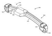
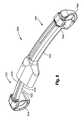
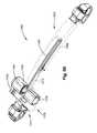
- FIG. 1is a front elevational view of an embodiment of a device
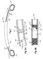
- FIG. 2Ais a front elevational view of an embodiment of a drive assembly
- FIG. 2Bis a front elevational view of an embodiment of a drive assembly
- FIG. 3is a perspective view of an embodiment of an activator and a device
- FIG. 4Ais a perspective view of an embodiment of an actuator
- FIG. 4Bis an exploded perspective view of an embodiment of an actuator
- FIG. 5Ais a schematic view of an embodiment of an activator and a magnet
- FIG. 5Bis a schematic view of an embodiment of an activator and a magnet
- FIG. 5Cis a schematic view of an embodiment of an activator and a magnet
- FIG. 5Dis a schematic view of an embodiment of an activator and a magnet
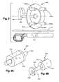
- FIG. 6Ais a schematic view of an embodiment of an actuator and a driving member
- FIG. 6Bis a schematic view of an embodiment of an actuator and a driving member
- FIG. 6Cis a schematic view of an embodiment of an actuator and a driving member
- FIG. 7is a perspective view of an embodiment of an actuator and a driving member
- FIG. 8is s perspective view of an embodiment of a device
- FIG. 9is a perspective view of a section of an embodiment of a device.
- FIG. 10is a side elevational view of an embodiment of a clutch mechanism and an actuator
- FIG. 11is a perspective view of an embodiment of a clutch mechanism
- FIG. 12Ais a side elevational view of the clutch mechanism and the actuator of FIG. 10 in a first position
- FIG. 12Bis a side elevational view of the clutch mechanism and the actuator of FIG. 10 in a second position
- FIG. 12Cis a side elevational view of the clutch mechanism and the actuator of FIG. 10 in a third position
- FIG. 12Dis a side elevational view of the clutch mechanism and the actuator of FIG. 10 in a fourth position
- FIG. 12Eis a side elevational view of the clutch mechanism and the actuator of FIG. 10 in a fifth position
- FIG. 12Fis a side elevational view of the clutch mechanism and the actuator of FIG. 10 in a sixth position
- FIG. 12Gis a side elevational view of the clutch mechanism and the actuator of FIG. 10 in a seventh position
- FIG. 12His a side elevational view of the clutch mechanism and the actuator of FIG. 10 in a eighth position
- FIG. 12Iis a side elevational view of the clutch mechanism and the actuator of FIG. 10 in a ninth position
- FIG. 13is a side elevational view of an embodiment of a clutch mechanism
- FIG. 14is a side elevational view of an embodiment of an actuator
- FIG. 15is a side elevational view of an embodiment of a clutch mechanism and an actuator
- FIG. 16is a front elevational view of an embodiment of a device
- FIG. 17is a perspective view of an embodiment of a device
- FIG. 18is a perspective view of a portion of an embodiment of a device
- FIG. 19Ais a top planar view of an embodiment of a device
- FIG. 19Bis a cross-sectional view of the device of FIG. 19A taken along lines 19 B- 19 B;
- FIG. 19Cis a top view of a section of the device of FIG. 19A ;
- FIG. 20is a cross-sectional view of a section of the device of FIG. 19A taken along lines 20 - 20 .
- FIG. 21is a front elevational view of an embodiment of a device
- FIG. 22is a front elevational view of a section of the device of FIG. 21 ;
- FIG. 23is a top planar view of an embodiment of a device
- FIG. 24is a top planar view of a section of the device of FIG. 24 ;
- FIG. 25Ais a front elevational view of an embodiment of a device
- FIG. 25Bis a cross-sectional view of a section of the device of FIG. 25A taken along line 25 B- 25 B;
- FIG. 26is a perspective view of an embodiment of a device
- FIG. 27is a front elevational view of the device of FIG. 26 ;
- FIG. 28is a perspective view of a section of the device of FIG. 26 .
- Such embodimentsrelate to a device for displacing tissue within the body of an animal, by way of non-limiting example, a person with spinothoracic deformity.
- a child with spinothoracic deformityoften requires an implant periodically adjusted to expand the ribcage to permit organs to freely grow thereunder without being crowded.
- Remote adjustmentrefers to the ability to adjust the device without having to undergo surgery or other invasive or non-invasive procedure.
- Device for displacing tissue 100 , 500can be substantially straight, curved, or have another shape in accordance with design choice.
- device 100 , 500may include a first member 120 , 520 having a rod 122 , 522 , which is preferably relatively smooth, and a second member 140 , 540 having a tubular member 142 , 542 .
- Rod 122 , 522 and tubular member 142 , 542are selectively displaceable with respect to each other, preferably telescopically or laterally displaceable.
- First member 120 , 520 and second member 140 , 540are preferably elongated and may relatively straight or curved. Furthermore, it is to be understood that whereas certain embodiments are described herein as having a drive member associated with a tubular member, the drive member may be associated with a rod and vice versa.
- device 100 , 500includes a drive assembly 200 , 600 which displaces first member 120 , 520 from second member 140 , 540 to extend and/or retract device 100 , 500 .
- tubular member 142 , 542includes an inner cavity 146 , 546 within which rod 122 , 522 can be received.
- first member 120 , 520includes a first attaching device 124 , 524 for attaching to a tissue within the body.
- second member 140 , 540includes a second attaching device 144 , 544 for attaching to a tissue within the body.
- the first and second attaching devicesmay be hooks, clamps, closed rings or other mechanisms that can attach to bone, for example, ribs. Examples of suitable clamps are described in U.S. Pat. No. 6,126,664 for “DEVICE AND METHOD FOR LOCATING AND RESECTING BONE;” U.S. Pat. No.
- first member 120 , 520may be displaced from second member 140 , 540 and the respective tissues are pushed away from each other.
- first member 120 , 520is attached to a rib and second attaching device 140 , 540 is attached to the hip, the rib bone can be pushed outward to correct or treat a spinothoracic deformity.
- drive member 210comprises an outer perimeter 214 preferably having at least a portion that is threaded 216 , and preferably is attached to rod 122 of first member 120 .
- the threads 216 on the outer perimeter 214may contact inner cavity 146 , inner cavity 146 preferably having a threaded portion 148 , and drive member 210 moves relative to the length of tubular member 142 .
- first member 120which is attached to drive member 210 , is also moved relative to the length of second member 140 , preferably within second member 140 , more preferably telescopically.
- drive member 210is shown as being attached to an end of rod 122 , it is to be understood that drive member 210 can be attached to rod 122 at another location relative to the length of rod 122 . It is to be understood that the term “rotation” encompasses a partial rotation less than 360°, a complete rotation of 360° or greater.
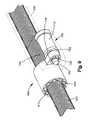
- Drive member 210can be rotated by an actuator 300 for example as shown in FIGS. 4 A,B.
- Actuator 300preferably includes a magnetic member, preferably a magnet 310 , and which is preferably activated by an external magnetic activator 400 .
- the embodiment of the actuator 300 illustratedis aligned with, preferably concentric with, drive member 210 , and includes a magnet 310 , preferably a cylindrical magnet having a first pole 312 and a second pole 314 , and a ring 320 preferably attached to magnet 310 such that the rotation of magnet 310 causes ring 320 to rotate.
- An alternate embodiment of the actuatormay be arranged parallel to, preferably offset from the drive member.
- first pole 312can be a north pole and second pole 314 can be a south pole.
- drive member 210is rotated, preferably in predetermined increments, thus extending or retracting device 100 in predetermined increments.
- Magnet 310can be rotated by a magnetic field external to the body, thus eliminating the need for an incision or invasive procedure to extend or retract device 100 .
- the aligned, preferably concentric, arrangement of actuator 300 and drive member 210can provide a substantially narrow device having a low profile, which may reduce patient discomfort and cause less tissue irritation.
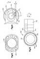
- FIGS. 3 , 5 A-DAn embodiment of external activator 400 is illustrated in FIGS. 3 , 5 A-D and preferably includes a face 440 having two or more, preferably four magnets 420 a , 420 b having a single pole each mounted on face 440 .
- external activator 400is preferably located above skin S.
- external activator 400includes two magnets 420 a having a north pole and two magnets 420 b having a south pole.
- the north poled magnets 420 a and the south poled magnets 420 bare arranged in an alternating order.
- face 440is rotated about an axis X by an activator bar 460 , a magnetic field can be created. Referring to FIGS.
- the arrangement of single pole magnets 420 a,bcan provide the desired rotation of magnet 310 as external activator 400 is rotated. As the single pole magnets 420 a,b move toward or away from actuator 300 , magnets 420 a,b create an attraction (solid arrows) and/or a rejection force (dashed lines) with magnet 310 to rotate magnet 310 .
- magnet 310is attached to a ring 320 having a ring rod 326 extending through the center of magnet 310 and a ring tab 322 as illustrated in FIG. 4B .
- Ring 320preferably comprises a durable material, such as a hard metal, more preferably a material that is not magnetic and thus unaffected by the external activator 400 .
- drive member 210it is preferably for drive member 210 not to be magnetic.
- Ring 320 and magnet 310can be attached, preferably permanently attached, for example, using an adhesive, a groove and projection, etc.
- Ring 320can also include a projection 324 extending away from magnet 310 about which drive member 210 can rotate.
- actuator 300when magnet 310 is rotated by external activator 400 , ring 320 also rotates and ring tab 322 contacts and pushes a tooth 212 of drive member 210 to rotate drive member 210 .
- the actuator 300may provide continuous rotation of drive member 210 with the continued rotation of magnet 310 to provide a smooth, continuous displacement of rod 120 .
- drive member 210may be rotated in increments of varying force or oscillate to obtain the necessary torque to rotate drive member 210 as described in more detail below.
- actuator 300can extend device 100 by rotating drive member 210 in one direction and retract device 100 when rotating in the opposite direction.
- actuator 300can rotate drive member 210 in one direction to extend device 100 without permitting retraction.
- Other options for the relationship between actuator and drive assembly 200are also available.
- Drive member 210preferably can be rotated if the static torque, namely the rotational force of actuator 300 as magnet 310 rotates, is greater than the work torque, namely the rotational force required to rotate drive member 210 .
- the static torquecan be dependent on various factors, such as, by way of non-limiting example, the distance between actuator 300 and external activator 400 , and the magnet material properties. Therefore, the static torque may be predetermined during manufacture. Once the work torque becomes greater than the static torque, actuator 300 does not rotate drive member 210 and magnet 310 ceases to rotate, preferably with ring tab 322 proximate tooth 212 .
- Magnet 310can then rotate in the opposite direction such that ring tab 322 rotates away from tooth 212 , preferably about 180°.
- magnet 310ceasing to rotate and subsequently rotating in the opposite direction occurs relatively quickly, more preferably such that magnet 310 appears to bounce back upon ring tab 322 contacting tooth 212 .
- activator 400preferably continues to rotate in a consistent direction without oscillating.
- the degree of rotation of magnet 310 away from tooth 212may be determined, for example, by the number of poles on the magnet 310 or actuator 300 . Therefore, ring tab 322 can be accelerated over a rotary angle of 180°, thus creating a greater static torque.
- the static torquesuch as the magnetic material, the mass, the diameter, the activator velocity, and the like.
- Such an effectmay be referred to as a “sledge hammer” effect due to the repeated impacting of the rotating ring tab 322 .
- FIGS. 6A-CSuch a relationship is illustrated in FIGS. 6A-C , wherein ring tab 322 retracts further and further away from tooth 322 to create a greater rotary angle and thus a greater static torque. Therefore the torque applied on drive member 210 may be substantially greater than the direct torque applied by the rotating magnet.
- such a static torqueis about 2 to 15 times greater, more preferably about ten times greater than the static torque of a rotating magnet 310 .
- actuator 300includes a magnet 310 that may be attached to a ring 320 at one end, and an end piece 330 at the opposite end that preferably prevents magnet 310 from being moved away from ring 320 .
- actuator 300may include an axis, such as an axle 340 about which magnet 310 and ring 320 can rotate, which preferably provides a gap and a relatively low friction coefficient between ring 320 and drive member 210 and between magnet 310 and end piece 330 .
- first member 520displaceable relative to the length of second member 540 by a drive assembly 600 , and further includes an actuator 700 that is adjacent to drive assembly 600 .
- first member 520includes a rod 522 having an outer perimeter 526 that is at least partially threaded 528 and second member 540 includes a tubular member 542 having an inner cavity 546 that is preferably substantially smooth.
- Drive assembly 600includes a drive member 610 preferably having a generally cylindrical shape and an outer perimeter 614 .
- Drive member 610comprises an inner surface 616 , at least a part of which is threaded and contacts the outer perimeter 526 of rod 522 of first member 520 , which is also at least partially threaded, thus permitting drive member 610 to move relative to the length of rod 522 .
- drive member 610is concentrically aligned with rod 522 .
- drive assembly 600includes a clutch mechanism, for example, a freewheel clutch 620 as shown in FIGS. 10-13 having one or more, preferably a plurality of stoppers such as needles or rollers 630 surrounded by an outer housing 620 which is preferably aligned with, more preferably concentrically aligned with, drive member 610 .
- freewheel clutch 620includes outer housing 640 surrounding and preferably concentrically aligned with drive member 610 .
- Freewheel clutch 620has a plurality of needles or rollers 630 positioned between outer housing 640 and drive member 610 .
- outer housing 640has inner walls 626 having an incline such that inner walls 626 include converging walls 626 a.
- needles 630can move, preferably roll, until they are wedged between converging walls 626 a and outer perimeter 614 of drive member 610 which stops further movement of the rollers 630 .
- Freewheel clutch 640can also include one or more springs 622 which urge needles 630 toward converging walls 626 a.
- outer housing 640is rotated in the opposite direction, namely, in a counter-clockwise direction, needles 630 can be released to move, preferably roll, toward diverging walls 626 b of outer housing 640 .
- the work torque required to rotate drive member 610 in a counter-clockwise directionis preferably greater than the force necessary for needles 630 to move or roll around the outer perimeter 614 of drive member 610 . Therefore needles 630 can roll toward diverging walls 626 b while drive member 610 remains in place.
- freewheel clutch 640may provide a ratcheting effect by providing a clockwise rotation but not a counter-clockwise rotation of drive member 610 .
- an alternate embodiment of freewheel clutch 620includes six needles 630 .
- rollers 630 of freewheel clutch 620are positioned equidistant from each other, the rollers need not be equidistant as illustrated in the embodiment of FIG. 13 .
- outer housing 640may have a partially flattened portion 642 which may provide a relatively low profile of device and reduce discomfort and cause less tissue irritation.
- An embodiment of drive assembly 600 as shown in FIGS. 10-12includes a lever 650 extending radially outward from freewheel clutch 620 and peripherally fixed thereto, lever 650 having an aperture generally indicated at 652 having an aperture surface 656 .
- Lever 650is preferably displaced by an actuator 700 comprising a rotating member 730 preferably having a generally cylindrical shape and a bulbous projection 732 that extends radially outward.
- rotating member 730can be an eccentric cam or disc.
- bulbous projection 732contacts aperture surface 656 as at least a portion of rotating member 730 rotates within aperture 656 .
- lever 650can be selectively displaced.
- actuator 700can include a magnet 710 , preferably a cylindrical magnet, which can be rotated by an external magnetic field.
- actuator 700includes a non-magnetic, hard metal ring 720 having a ring tab 722 .
- actuator 700can be similar to actuator 300 of FIG. 3 described above, wherein a ring tab 722 can contact a rotating member 730 to force rotation of rotating member 730 about an actuator rod 750 .
- ring tab 722can push bulbous projection 732 as ring tab 722 rotates.
- rotating member 730can include a tooth 734 extending toward ring 720 , which ring tab 722 can contact, resulting in rotating member 730 rotating.
- rotating member 730can be rotated by magnet 710 directly, thus maintaining the same torque as the rotating magnet 710 .
- actuator 700can include a reduction gear, for example, a gear train such that a plurality of rotations of magnet 710 can result in a single rotation of a gear at a greater torque. It is to be understood that other embodiments of the actuator are within the scope of the invention as a matter of design choice.
- FIGS. 12A-IAn example of the way in which freewheel clutch 620 works is illustrated in FIGS. 12A-I , wherein the sequential relationship between drive assembly 600 and rotating member 730 is illustrated in positions (1)-(9) as rotating member 730 is rotated in a clockwise direction.
- position (1)bulbous projection 732 contacts the aperture surface 656 of lever 650 .
- bulbous projection 732moves along aperture surface 656 in a clockwise direction and pushes lever 650 in direction A, thus rotating outer housing 640 in a clockwise direction as shown in subsequent positions (2) and (3).
- the clockwise rotation of outer housing 640results in the rotation of drive member 610 in the clockwise direction as indicated by the arrows 645 .
- outer housing 640rotates in a clockwise direction
- needles 630are stopped by converging inner walls 626 a of outer housing 640 until needles 630 are wedged between converging walls 626 a and outer perimeter 614 of drive member 610 .
- a clockwise torqueis preferably generated, for example, by a frictional force evoked by the wedged needles 630 . Therefore, the greater the torque generated, the more needles 630 may become wedged, thus increasing the frictional force between outer perimeter 614 of drive member 610 and needles 630 and substantially preventing needles 630 from sliding or rolling along outer perimeter 614 of drive member 610 . Therefore, as outer housing 640 continues to rotate, drive member 610 can be rotated in a clockwise direction.
- Position (3)shows drive assembly 600 when lever 650 is displaced the maximum distance in direction A. Once this position (3) is passed, bulbous projection 732 enters a clearance 646 in aperture 652 in position (4) such that as rotating bulbous projection 732 continues to rotate in a clockwise direction, lever 650 is not displaced.
- bulbous projection 732moves along aperture surface 656 of lever 650 as shown in position (5) and displaces lever 650 in direction B until lever 650 is displaced the maximum distance in direction B as shown in position (6).
- outer housing 640rotates in a counter-clockwise direction.
- needles 630are permitted to roll toward diverging walls 626 b of outer housing 640 . Therefore, outer housing 640 can rotate in a counter-clockwise direction without resulting in the rotation of drive member 610 , thus preferably providing a ratcheting effect.
- bulbous projection 732preferably enters a clearance 647 in aperture 652 such that as rotating bulbous projection 732 continues to rotate in a clockwise direction, lever 650 is not displaced, as shown in positions (7)-(8).
- bulbous projection 732has rotated 360° and has returned to position (1), and the process can be repeated until the desired rotation of drive member 610 is reached, and thus the desired extension or retraction of device 500 . It is to be understood that the magnet may also rotate in the other direction.
- drive assembly 600preferably provides a ratcheting effect, by rotating drive member 610 in one direction and not the other, while lever 650 is displaced back and forth in directions A and B.
- the coordination of drive assembly 600 and actuator 700can provide a magnified torque on drive member 610 compared to the torque of the rotating magnet 710 or rotating element 730 .
- bulbous projection 732preferably contacts lever 650 at approximately 45°, and the preferred displacement D of lever 650 in direction A is approximately 0.2 mm.
- Thiscan provide a total displacement of lever 650 of about 0.4 mm and a rotation of 2.3° with lever 650 having a length of about 10 mm between a center 718 of magnet 710 and a center 628 of freewheel clutch 620 .
- the identified dimensions and anglesare merely exemplary and not intended to limit the scope of the invention. Rather, the dimensions and angles can be varied as a matter of application specific design choice without deviating from the scope of the invention.
- drive assembly 660can include a drive member 662 having a plurality of teeth 664 and grooves 668 within an outer housing 661 , drive member 662 being preferably concentrically aligned with outer housing 661 .
- Outer housing 661is preferably associated with a lever 670 having a shaft 672 having a projection 674 constructed and arranged to be selectively received within grooves 668 of drive member 662 .
- lever 670As illustrated in FIG. 15 , as lever 670 is displaced in direction A, projection 674 of shaft 672 is received within a groove 668 of drive member 662 and applies a force in direction A, thus rotating drive member 662 in a clockwise direction.
- lever 670is displaced in direction B, however, because of the angle of teeth 664 and projection 674 of shaft 672 , projection 674 of shaft 672 glides across teeth and thus drive member 660 does not rotate in the clock-wise direction, thus creating a ratcheting effect.
- the displacement of lever 670can be activated by a magnetic actuator, for example, actuator 700 as illustrated in FIG. 9 .
- drive assembly 600 having a lever 650has been illustrated herein as rotating drive member 610 along rod 522 of first member 520 , it is to be understood that drive member 610 can be rotated within tubular member 542 of second member 540 without deviating from the scope of the invention.
- drive assembly 200 having a magnetic actuator 300 coaxial theretois illustrated as rotating drive member 210 within the threaded inner cavity 146 of tubular member 142 , it is to be understood that drive member 210 can be rotated along rod 122 of first member 120 as a matter of design choice without deviating from the scope of the invention. Alternate embodiments are also contemplated.
- drive assembly 600 and actuator 700may be enclosed in a housing to at least substantially prevent tissue irritation during the rotation of the magnet 719 or drive member 610 .
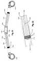
- an embodiment of a device 900can include a first member 920 and a second member 940 that are selectively displaceable relative to each other, preferably along the length of one another, more preferably telescopically displaceable, by a drive assembly 950 having a drive member 942 .
- First member 920can include an elongated rod 922 and second member 940 can include an elongated tubular member 942 within which elongated rod 922 can be telescopically displaced to extend or retract device 900 .
- first member 920 and second member 940can be constructed and arranged such that as device 900 extends and contracts, a part of first member 920 moves along the side of a part of second member 940 , such as for example adjacent rods.
- Drive member 952 as shownmay be fixed, preferably permanently, to tubular member 942 , wherein drive member 952 , and thus tubular member 942 , can move relative to the length of rod 922 .
- certain embodiments of the devicehas a curvature, and more preferably has a radius of curvature of about 220 mm. Such curvature may be beneficial for use with a spine, for example, within a chest wall.
- device 900may be constructed to substantially minimize tissue resistance, for example, when device 900 is being extended.
- tubular member 942may include a relatively sharp edge 944 which preferably cuts through the tissue within a patient's body as device 900 is being extended. Such a sharp edge 944 may be additionally helpful, for example, when a portion 946 of tubular member 942 projects away from rod 922 . Whereas portion 946 can be utilized for a variety of functions, portion 946 may be utilized to manually push tubular member 942 , or portion 946 can house a lever, actuator, magnet, gears, and the like.
- rod 922includes a generally cross-shaped or (X shape) cross section, four sides 924 a,b , 926 a,b and has at least a partially threaded portion 928 .
- rod 922can include two threaded sides 924 a,b having a first radius of curvature, and two smooth sides 926 a,b having a second radius of curvature preferably different from the first curvature, wherein threaded sides 924 a,b and smooth sides 926 a,b are alternatingly positioned around the perimeter of rod 922 .
- drive member 952includes a threaded portion 954 which can contact threaded sides 924 to move relative to the length of rod 922 as well as remain in place without slipping.
- Smooth sides 926 a,bpreferably do not contact drive member 952 and therefore do not create interference against drive member 952 .
- smooth sides 926 a,bhave a smaller diameter than threaded sides 924 a,b , thus facilitating not contacting drive member 952 .
- device 900may have a top 912 a and a bottom 912 b , wherein device 900 curves from top 912 a toward bottom 912 b .
- Threaded sides 914 a,bmay be proximate the sides 916 of device 900 .
- threaded sides 924 a,bare not proximate bottom 912 b where the distance between the threads may decrease, thus creating clumping of threads.
- providing a smaller diameter of smooth sides 926 a,bmay prevent jamming the bottom of drive member 952 .
- rod 922may include more or less threaded sides 924 a,b or smooth sides 926 a,b , and the positioning of threaded sides 924 a,b and smooth sides 926 a,b on rod 922 may be altered as a matter of design choice.
- tubular member 942may include a slot generally indicated at 944 through which rod 922 can be seen and accessed.
- This embodiment of device 900can facilitate manufacture by providing slot 944 for access by a machine tool while maintaining device 900 relatively compact.
- FIG. 20illustrates a cross section of an exemplary embodiment of drive member 952 positioned along the length of rod 922 , the cross section take along line 20 - 20 of FIG. 19A .
- Drive member 952preferably comprises a generally cylindrical shape and a threaded portion 954 proximate the middle region of drive member 952 , threaded portion 954 constructed and arranged to contact threaded sides 924 of rod 922 preferably with non-threaded regions proximate both end portions 956 .
- Drive membermay be operably associated with a rotating mechanism, such as a freewheel clutch 958 for rotating drive member 952 .
- threaded portion 954is approximately 4 mm long, and end portions 956 of drive member 952 do not include threads. There is preferably no interference between end portions 956 and rod 922 , which may facilitate the rotation of drive member 952 along rod 922 having a curvature.
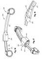
- a device 1000can include two or more first members 1020 having rods 1022 , two or more second members 1040 having tubular members 1042 , two or more drive members 1110 associated with, preferably fixed to rods 1022 and located within tubular members 1042 , and an actuator 1100 having a magnet 1120 .
- Rods 1022 and tubular members 1042may be relatively curved or straight, more preferably straight.
- device 1000may include two relatively straight first members 1020 positioned at an angle with respect to each other. Therefore, device 1000 may better fit the body of the patient while facilitating manufacture.
- magnet 1120is a rotatable magnet associated with rods 1022 such that the rotation of magnet 1120 results in the rotation of rods 1022 , preferably simultaneously.
- Actuator 1100is preferably associated with rods 1022 via a flexible coupling 1002 , such as a cardan coupling or universal joint.
- Drive member 1110can be associated with, preferably fixed to, rods 1022 , such that the rotation of rods 1022 rotates drive members 1110 .
- Magnet 1120preferably can be rotated by an actuator located outside the skin.
- tubular member 1042preferably includes an inner cavity 1046 having a threaded region 1044 .
- Drive members 1110preferably include a threaded region 1114 on its outer perimeter 1112 , thus contacting threads 1044 of tubular members 1042 to move drive members 1110 relative to the length of tubular members 1042 .
- Second members 1040can include an attaching element 1044 to attach to tissue in the body of an animal and a tubular member 1042 . Therefore, as first members 1020 are displaced relative to the length of second members 1040 , device 1000 can be extended or retracted accordingly, thus moving the tissues of the body closer together or further apart. Such an arrangement may facilitate manufacturing device 1000 , and can be beneficial by partially straightening out as device 1000 is extended, especially in patients where a device having a fixed curvature may lead to a too strong kyphosis when fully expanded. Furthermore, drive assembly 1100 preferably remains fixed within the patient's body regardless of how much device 1000 is extended or retracted.
- first members 1020include housings 1024 for enclosing rods 1022 .
- Housings 1024may include grooves 1026 , preferably running externally along the length of housing 1024 .
- Tubular members 1042may include projections or pins 1046 projecting toward housings 1024 .
- Pins 1046are preferably constructed and arranged to be received within groove 1026 to substantially prevent the rotation of tubular member 1042 with respect to housing 1024 and vice versa, thus substantially preventing device 1000 from rotating within the patient's body.
- FIGS. 23-24illustrate an embodiment of device 1200 having a first freewheel clutch 1210 for two or more rotating rods 1222 in a first direction, and a second freewheel clutch 1220 to prevent rods 1222 from rotating in a second direction opposite to the first direction.
- first freewheel clutch 1210is associated to a magnet 1230
- second freewheel clutch 1220is associated with, preferably fixed to, a housing 1240 substantially enclosing second freewheel clutch 1220 .
- a device 1200 as describedmay be beneficial in situations when each rotation of first freewheel clutch 1210 is insufficient to transfer enough torque to rotate drive members 1260 . In such a situation, rods 1222 may oscillate back and forth without rotating drive members 1260 .
- Second freewheel clutch 1220may at least substantially prevent the oscillation of rods 1222 by preventing the reverse rotation of rods 1222 .
- FIGS. 25A-Billustrate another embodiment of device 1050 having two attaching members 1070 , each attaching member 1070 having a rod 1074 .
- Device 1050may further include one or more connecting members 1060 to connect the two attaching members 1070 to each other.
- Attaching members 1070may have an attachment mechanism 1052 for attaching to the tissue, such as a bone, in a body.
- connecting member 1060may include two tubular members 1062 arranged at an angle less than 180 degrees relative to each other, tubular member 1062 constructed and arranged to receive rod 1074 .
- Tubular member 1062may be connected to a driving member 1066 , driving member 1066 preferably rotatable about rod 1074 , wherein rod 1074 may include a threaded region 1076 .
- Driving member 1066may include a threaded inner perimeter 1068 constructed and arranged to contact threaded region 1076 of rod 1074 to displace attaching member 1070 relative to connecting member 1060 .
- connecting member 1060may include an actuator, for example, a rotatable magnet 1064 connected to a contact member 1065 .
- contact member 1065includes a tab 1065 a for contacting a tooth 1066 a of driving member 1066 .
- driving member 1066may rotate, thus displacing attaching member 1070 relative to connecting member 1060 .
- magnet 1064can oscillate to provide a ratcheting effect on driving member 1066 .
- device 1050includes two magnets 1064 which are arranged such that a common activator may be utilized to rotate both magnets 1064 in the same direction, thus displacing both attaching members 1070 relative to connecting member 1060 .
- Attaching member 1070preferably includes a housing 1072 constructed and arranged to contain rod 1074 and also possibly a portion, if any, of tubular member 1062 . Whereas attaching member 1070 is described herein as including rod 1074 and connecting member 1060 is described herein as including tubular member 1062 , it is contemplated that attaching member 1070 may include tubular member 1062 and connecting member 1060 may include rod 1074 .
- FIGS. 26-27wherein an embodiment of device 1300 is illustrated having a first member 1310 having a rod 1312 and a second member 1320 having a tubular member 1322 , further including a drive assembly 1330 associated with rod 1312 for selectively displacing first member 1310 with respect to second member 1320 .
- drive assembly 1330may include a magnetic actuator 1332 for activating a first freewheel clutch 1334 which preferably rotates a shaft 1336 which winds a cable 1340 preferably about shaft 1336 .
- cable 1340is received within a channel 1313 a which runs along the length of rod 1312 on a first side 1314 and a channel 1313 b which runs along the length of rod 1312 on a second side 1315 such that when cable 1340 is being wound about shaft 1336 , cable 1340 moves in a first direction C in channel 1313 a and in a second direction D, preferably different from first direction C, in channel 1313 b .
- FIGS. 26-28illustrated an embodiment of device 1300 wherein first side 1314 is different from second side 1315 , it is to be understood that first side 1314 and second side 1315 may be the same side as a matter of design choice.
- a first end 1342 of cable 1340is connected, more preferably fixed, to tubular member 1322 . Therefore, as first freewheel clutch 1334 is rotated, cable 1340 is wound about shaft 1336 and first end 1342 of cable 1340 is pulled in direction D, thus displacing tubular member 1322 in direction D, away from drive assembly 1330 and thus extending device 1300 .
- Drive assembly 1330may also include a second freewheel clutch 1339 connected to shaft 1336 to prevent the reverse rotation of shaft 1336 .
- One embodiment of the actuatormay include a gear train.
- a gear traincan be provided between the magnet and the rotating member, or between the rotating member and the drive member as a matter of design choice. It is to be understood that a gear train may be provided at various portions of the device, such as the drive assembly.
- One preferred embodiment of the devicehas a length of about 10 to 200 mm, more preferably about 20 to 180, most preferably about 30 to 150 mm when fully contracted. Additionally, one embodiment of the device has a length of about 20 to 400 mm, more preferably about 30 to 350 mm, most preferably about 40 to 300 mm when fully extended.
- the radius of curvature of the deviceis preferably between about 100 and 300 mm, more preferably between about 150 and 250 mm, most preferably about 220 mm.
- the preferred shape, length, curvature, and the like, of the devicevaries according to the body in which the device is to be inserted, preferably implanted.
- driving membermay have internal threading, and vice versa, as a matter of design choice. For example, providing internal threading may provide an increased driving force.
Landscapes
- Health & Medical Sciences (AREA)
- Orthopedic Medicine & Surgery (AREA)
- Surgery (AREA)
- Life Sciences & Earth Sciences (AREA)
- Heart & Thoracic Surgery (AREA)
- Nuclear Medicine, Radiotherapy & Molecular Imaging (AREA)
- Engineering & Computer Science (AREA)
- Biomedical Technology (AREA)
- Medical Informatics (AREA)
- Molecular Biology (AREA)
- Animal Behavior & Ethology (AREA)
- General Health & Medical Sciences (AREA)
- Public Health (AREA)
- Veterinary Medicine (AREA)
- Neurology (AREA)
- Prostheses (AREA)
- Surgical Instruments (AREA)
Abstract
Description
Claims (9)
Priority Applications (4)
| Application Number | Priority Date | Filing Date | Title |
|---|---|---|---|
| US11/697,085US8016837B2 (en) | 2006-04-06 | 2007-04-05 | Remotely adjustable tissue displacement device |
| US13/230,042US8894663B2 (en) | 2006-04-06 | 2011-09-12 | Remotely adjustable tissue displacement device |
| US14/551,879US9259243B2 (en) | 2006-04-06 | 2014-11-24 | Remotely adjustable tissue displacement device |
| US15/043,731US10105130B2 (en) | 2006-04-06 | 2016-02-15 | Remotely adjustable tissue displacement device |
Applications Claiming Priority (4)
| Application Number | Priority Date | Filing Date | Title |
|---|---|---|---|
| US79058906P | 2006-04-06 | 2006-04-06 | |
| US86673906P | 2006-11-21 | 2006-11-21 | |
| US11/697,085US8016837B2 (en) | 2006-04-06 | 2007-04-05 | Remotely adjustable tissue displacement device |
| PCT/US2007/066115WO2007118179A2 (en) | 2006-04-06 | 2007-04-05 | Remotely adjustable tissue displacement device |
Related Child Applications (1)
| Application Number | Title | Priority Date | Filing Date |
|---|---|---|---|
| US13/230,042DivisionUS8894663B2 (en) | 2006-04-06 | 2011-09-12 | Remotely adjustable tissue displacement device |
Publications (2)
| Publication Number | Publication Date |
|---|---|
| US20070270803A1 US20070270803A1 (en) | 2007-11-22 |
| US8016837B2true US8016837B2 (en) | 2011-09-13 |
Family
ID=38921812
Family Applications (1)
| Application Number | Title | Priority Date | Filing Date |
|---|---|---|---|
| US11/697,085Active2029-12-16US8016837B2 (en) | 2006-04-06 | 2007-04-05 | Remotely adjustable tissue displacement device |
Country Status (7)
| Country | Link |
|---|---|
| US (1) | US8016837B2 (en) |
| EP (2) | EP2997916B1 (en) |
| JP (1) | JP5095723B2 (en) |
| AU (1) | AU2007234790A1 (en) |
| BR (1) | BRPI0709893A2 (en) |
| CA (1) | CA2648082C (en) |
| WO (1) | WO2007118179A2 (en) |
Cited By (32)
| Publication number | Priority date | Publication date | Assignee | Title |
|---|---|---|---|---|
| US20100137913A1 (en)* | 2008-11-03 | 2010-06-03 | Roberto Khatchadourian | Adjustable rod assembly |
| US20120157996A1 (en)* | 2007-10-30 | 2012-06-21 | Ellipse Technologies, Inc. | Skeletal manipulation method |
| US20130150889A1 (en)* | 2011-12-12 | 2013-06-13 | Stephen D. Fening | Noninvasive device for adjusting fastener |
| US20150105826A1 (en)* | 2013-10-10 | 2015-04-16 | Ellipse Technologies, Inc. | Adjustable spinal implant |
| WO2015192032A1 (en)* | 2014-06-12 | 2015-12-17 | Austen Bioinnovation Institute In Akron | Noninvasive device for adjusting fastener |
| US9259243B2 (en) | 2006-04-06 | 2016-02-16 | DePuy Synthes Products, Inc. | Remotely adjustable tissue displacement device |
| US20180028233A1 (en)* | 2011-06-03 | 2018-02-01 | K2M, Inc. | Spinal correction system actuators |
| US10016220B2 (en) | 2011-11-01 | 2018-07-10 | Nuvasive Specialized Orthopedics, Inc. | Adjustable magnetic devices and methods of using same |
| US10039661B2 (en) | 2006-10-20 | 2018-08-07 | Nuvasive Specialized Orthopedics, Inc. | Adjustable implant and method of use |
| US10092328B2 (en) | 2015-01-13 | 2018-10-09 | Stryker European Holdings I, Llc | Growing rods and methods of use |
| US10206719B2 (en) | 2016-12-16 | 2019-02-19 | Nuvasive, Inc. | Bone hook apparatus |
| US10238427B2 (en) | 2015-02-19 | 2019-03-26 | Nuvasive Specialized Orthopedics, Inc. | Systems and methods for vertebral adjustment |
| US10271885B2 (en) | 2014-12-26 | 2019-04-30 | Nuvasive Specialized Orthopedics, Inc. | Systems and methods for distraction |
| US10405891B2 (en) | 2010-08-09 | 2019-09-10 | Nuvasive Specialized Orthopedics, Inc. | Maintenance feature in magnetic implant |
| US10478232B2 (en) | 2009-04-29 | 2019-11-19 | Nuvasive Specialized Orthopedics, Inc. | Interspinous process device and method |
| US10517643B2 (en) | 2009-02-23 | 2019-12-31 | Nuvasive Specialized Orthopedics, Inc. | Non-invasive adjustable distraction system |
| US10617453B2 (en) | 2015-10-16 | 2020-04-14 | Nuvasive Specialized Orthopedics, Inc. | Adjustable devices for treating arthritis of the knee |
| US10646262B2 (en) | 2011-02-14 | 2020-05-12 | Nuvasive Specialized Orthopedics, Inc. | System and method for altering rotational alignment of bone sections |
| US10660675B2 (en) | 2010-06-30 | 2020-05-26 | Nuvasive Specialized Orthopedics, Inc. | External adjustment device for distraction device |
| US10675064B2 (en) | 2011-12-12 | 2020-06-09 | Children's Hospital Medical Center Of Akron | Distraction Osteogenesis system |
| US10729470B2 (en) | 2008-11-10 | 2020-08-04 | Nuvasive Specialized Orthopedics, Inc. | External adjustment device for distraction device |
| US10743794B2 (en) | 2011-10-04 | 2020-08-18 | Nuvasive Specialized Orthopedics, Inc. | Devices and methods for non-invasive implant length sensing |
| US10835292B2 (en) | 2018-06-13 | 2020-11-17 | Nuvasive, Inc. | Rib fixation device and related methods |
| US10835290B2 (en) | 2015-12-10 | 2020-11-17 | Nuvasive Specialized Orthopedics, Inc. | External adjustment device for distraction device |
| US10918425B2 (en) | 2016-01-28 | 2021-02-16 | Nuvasive Specialized Orthopedics, Inc. | System and methods for bone transport |
| US11065037B2 (en) | 2016-05-19 | 2021-07-20 | Auctus Surgical, Inc. | Spinal curvature modulation systems and methods |
| US11191579B2 (en) | 2012-10-29 | 2021-12-07 | Nuvasive Specialized Orthopedics, Inc. | Adjustable devices for treating arthritis of the knee |
| US11202707B2 (en) | 2008-03-25 | 2021-12-21 | Nuvasive Specialized Orthopedics, Inc. | Adjustable implant system |
| US11246694B2 (en) | 2014-04-28 | 2022-02-15 | Nuvasive Specialized Orthopedics, Inc. | System for informational magnetic feedback in adjustable implants |
| US11357549B2 (en) | 2004-07-02 | 2022-06-14 | Nuvasive Specialized Orthopedics, Inc. | Expandable rod system to treat scoliosis and method of using the same |
| US11446064B2 (en) | 2018-04-26 | 2022-09-20 | Stryker European Operations Holdings Llc | Orthopedic growing devices |
| US12262917B2 (en) | 2016-05-19 | 2025-04-01 | Auctus Surgical, Inc. | Spinal curvature modulation systems and methods |
Families Citing this family (89)
| Publication number | Priority date | Publication date | Assignee | Title |
|---|---|---|---|---|
| US7464847B2 (en) | 2005-06-03 | 2008-12-16 | Tyco Healthcare Group Lp | Surgical stapler with timer and feedback display |
| US10285694B2 (en) | 2001-10-20 | 2019-05-14 | Covidien Lp | Surgical stapler with timer and feedback display |
| AU2003243219B2 (en) | 2003-05-09 | 2009-10-29 | Covidien Lp | Anastomotic staple with fluid dispensing capillary |
| US8114158B2 (en) | 2004-08-03 | 2012-02-14 | Kspine, Inc. | Facet device and method |
| US9717537B2 (en)* | 2004-08-30 | 2017-08-01 | Globus Medical, Inc. | Device and method for treatment of spinal deformity |
| CA2609970C (en) | 2005-06-03 | 2014-08-12 | Tyco Healthcare Group Lp | Battery powered surgical instrument |
| US11291443B2 (en) | 2005-06-03 | 2022-04-05 | Covidien Lp | Surgical stapler with timer and feedback display |
| US8016837B2 (en)* | 2006-04-06 | 2011-09-13 | Synthes Usa, Llc | Remotely adjustable tissue displacement device |
| US8246533B2 (en) | 2006-10-20 | 2012-08-21 | Ellipse Technologies, Inc. | Implant system with resonant-driven actuator |
| US8398637B2 (en)* | 2006-11-06 | 2013-03-19 | Douglas Eric Parsell | Device and method for less invasive surgical stabilization of pelvic fractures |
| US7431188B1 (en) | 2007-03-15 | 2008-10-07 | Tyco Healthcare Group Lp | Surgical stapling apparatus with powered articulation |
| US8800837B2 (en) | 2007-04-13 | 2014-08-12 | Covidien Lp | Powered surgical instrument |
| US7950560B2 (en) | 2007-04-13 | 2011-05-31 | Tyco Healthcare Group Lp | Powered surgical instrument |
| US11259801B2 (en) | 2007-04-13 | 2022-03-01 | Covidien Lp | Powered surgical instrument |
| US20080255413A1 (en) | 2007-04-13 | 2008-10-16 | Michael Zemlok | Powered surgical instrument |
| US7823760B2 (en) | 2007-05-01 | 2010-11-02 | Tyco Healthcare Group Lp | Powered surgical stapling device platform |
| US7931660B2 (en) | 2007-05-10 | 2011-04-26 | Tyco Healthcare Group Lp | Powered tacker instrument |
| US7556185B2 (en) | 2007-08-15 | 2009-07-07 | Tyco Healthcare Group Lp | Surgical instrument with flexible drive mechanism |
| US7922063B2 (en) | 2007-10-31 | 2011-04-12 | Tyco Healthcare Group, Lp | Powered surgical instrument |
| WO2009120764A2 (en) | 2008-03-25 | 2009-10-01 | Ellipse Technologies, Inc. | Systems and methods for adjusting an annuloplasty ring with an integrated magnetic drive |
| AU2009241686B2 (en)* | 2008-04-30 | 2015-01-22 | Moximed, Inc. | Surgical implantation method and devices for an extra-articular mechanical energy absorbing apparatus |
| US11241257B2 (en) | 2008-10-13 | 2022-02-08 | Nuvasive Specialized Orthopedics, Inc. | Spinal distraction system |
| US20100094303A1 (en)* | 2008-10-13 | 2010-04-15 | Arvin Chang | Spinal distraction system |
| US8828058B2 (en) | 2008-11-11 | 2014-09-09 | Kspine, Inc. | Growth directed vertebral fixation system with distractible connector(s) and apical control |
| US8043338B2 (en)* | 2008-12-03 | 2011-10-25 | Zimmer Spine, Inc. | Adjustable assembly for correcting spinal abnormalities |
| US8357182B2 (en) | 2009-03-26 | 2013-01-22 | Kspine, Inc. | Alignment system with longitudinal support features |
| US8821514B2 (en) | 2009-06-08 | 2014-09-02 | Covidien Lp | Powered tack applier |
| JP5751642B2 (en)* | 2009-09-04 | 2015-07-22 | エリプス テクノロジーズ, インク.Ellipse Technologies, Inc. | Bone growth apparatus and method |
| US9168071B2 (en) | 2009-09-15 | 2015-10-27 | K2M, Inc. | Growth modulation system |
| US8361069B2 (en) | 2009-09-25 | 2013-01-29 | Covidien Lp | Energized needles for wound sealing |
| JP2013512040A (en)* | 2009-11-25 | 2013-04-11 | スパイン21エル・ティー・ディー | Spinal rod with adjustable dimensions after surgery |
| US8568457B2 (en)* | 2009-12-01 | 2013-10-29 | DePuy Synthes Products, LLC | Non-fusion scoliosis expandable spinal rod |
| FR2957776B1 (en)* | 2010-03-23 | 2013-02-15 | Arnaud Andre Soubeiran | DEVICE FOR MOVING TISSUES INSIDE THE ORGANISM, ESPECIALLY BONE TISSUES, WITH FIXED TRACTION SCREWS AND ROTATING NUT |
| US8641723B2 (en) | 2010-06-03 | 2014-02-04 | Orthonex LLC | Skeletal adjustment device |
| US8282671B2 (en) | 2010-10-25 | 2012-10-09 | Orthonex | Smart device for non-invasive skeletal adjustment |
| US8721566B2 (en) | 2010-11-12 | 2014-05-13 | Robert A. Connor | Spinal motion measurement device |
| AU2011331999B2 (en) | 2010-11-22 | 2016-07-21 | Synthes Gmbh | Non-fusion scoliosis expandable spinal rod |
| FR2975582B1 (en)* | 2011-05-23 | 2013-06-07 | Ass Marie Lannelongue | OSTEOSYNTHESIS IMPLANT |
| US9724132B2 (en) | 2011-08-31 | 2017-08-08 | DePuy Synthes Products, Inc. | Devices and methods for cervical lateral fixation |
| US9451987B2 (en) | 2011-11-16 | 2016-09-27 | K2M, Inc. | System and method for spinal correction |
| US9468469B2 (en) | 2011-11-16 | 2016-10-18 | K2M, Inc. | Transverse coupler adjuster spinal correction systems and methods |
| US8920472B2 (en) | 2011-11-16 | 2014-12-30 | Kspine, Inc. | Spinal correction and secondary stabilization |
| WO2014172632A2 (en) | 2011-11-16 | 2014-10-23 | Kspine, Inc. | Spinal correction and secondary stabilization |
| US20130338714A1 (en) | 2012-06-15 | 2013-12-19 | Arvin Chang | Magnetic implants with improved anatomical compatibility |
| US9572601B2 (en)* | 2012-10-17 | 2017-02-21 | K2M, Inc. | Spinal correction adjustment systems and methods |
| US9044281B2 (en) | 2012-10-18 | 2015-06-02 | Ellipse Technologies, Inc. | Intramedullary implants for replacing lost bone |
| US9084591B2 (en) | 2012-10-23 | 2015-07-21 | Neurostructures, Inc. | Retractor |
| US9179938B2 (en) | 2013-03-08 | 2015-11-10 | Ellipse Technologies, Inc. | Distraction devices and method of assembling the same |
| US10226242B2 (en) | 2013-07-31 | 2019-03-12 | Nuvasive Specialized Orthopedics, Inc. | Noninvasively adjustable suture anchors |
| US9801734B1 (en) | 2013-08-09 | 2017-10-31 | Nuvasive, Inc. | Lordotic expandable interbody implant |
| US9468471B2 (en) | 2013-09-17 | 2016-10-18 | K2M, Inc. | Transverse coupler adjuster spinal correction systems and methods |
| US9931138B2 (en)* | 2014-10-15 | 2018-04-03 | Globus Medical, Inc. | Orthopedic extendable rods |
| KR102588501B1 (en) | 2014-10-23 | 2023-10-11 | 누베이시브 스페셜라이즈드 오소페딕스, 인크. | Remotely adjustable interactive bone reshaping implant |
| WO2017139548A1 (en) | 2016-02-10 | 2017-08-17 | Nuvasive Specialized Orthopedics, Inc. | Systems and methods for controlling multiple surgical variables |
| WO2018187797A1 (en)* | 2017-04-07 | 2018-10-11 | K2M, Inc. | Transverse connector |
| US11311295B2 (en) | 2017-05-15 | 2022-04-26 | Covidien Lp | Adaptive powered stapling algorithm with calibration factor |
| US11207066B2 (en) | 2017-10-30 | 2021-12-28 | Covidien Lp | Apparatus for endoscopic procedures |
| US12185949B2 (en) | 2017-10-30 | 2025-01-07 | Covidien Lp | Apparatus for endoscopic procedures |
| US10987104B2 (en) | 2017-10-30 | 2021-04-27 | Covidien Lp | Apparatus for endoscopic procedures |
| US11497490B2 (en) | 2018-07-09 | 2022-11-15 | Covidien Lp | Powered surgical devices including predictive motor control |
| US12137902B2 (en) | 2018-07-25 | 2024-11-12 | Covidien Lp | Adaptive anti-twitch algorithm for powered surgical devices |
| US11197734B2 (en) | 2018-10-30 | 2021-12-14 | Covidien Lp | Load sensing devices for use in surgical instruments |
| US11369372B2 (en) | 2018-11-28 | 2022-06-28 | Covidien Lp | Surgical stapler adapter with flexible cable assembly, flexible fingers, and contact clips |
| US11202635B2 (en) | 2019-02-04 | 2021-12-21 | Covidien Lp | Programmable distal tilt position of end effector for powered surgical devices |
| US11376006B2 (en) | 2019-02-06 | 2022-07-05 | Covidien Lp | End effector force measurement with digital drive circuit |
| JP2022519380A (en) | 2019-02-07 | 2022-03-23 | ニューベイシブ スペシャライズド オーソペディックス,インコーポレイテッド | Ultrasonic communication in medical devices |
| US11589901B2 (en)* | 2019-02-08 | 2023-02-28 | Nuvasive Specialized Orthopedics, Inc. | External adjustment device |
| US11219461B2 (en) | 2019-03-08 | 2022-01-11 | Covidien Lp | Strain gauge stabilization in a surgical device |
| US11458244B2 (en) | 2020-02-07 | 2022-10-04 | Covidien Lp | Irrigating surgical apparatus with positive pressure fluid |
| US11553913B2 (en) | 2020-02-11 | 2023-01-17 | Covidien Lp | Electrically-determining tissue cut with surgical stapling apparatus |
| US12029470B2 (en) | 2020-05-21 | 2024-07-09 | Covidien Lp | Simultaneous RF monopolar calibration using a shared return electrode |
| US11622768B2 (en) | 2020-07-13 | 2023-04-11 | Covidien Lp | Methods and structure for confirming proper assembly of powered surgical stapling systems |
| US12213708B2 (en) | 2020-09-08 | 2025-02-04 | Nuvasive Specialized Orthopedics, Inc. | Remote control module for adjustable implants |
| US12193884B2 (en) | 2020-11-17 | 2025-01-14 | Covidien Lp | Contactless force measurement of motor torque in powered surgical device |
| US11744580B2 (en) | 2020-11-24 | 2023-09-05 | Covidien Lp | Long stapler reloads with continuous cartridge |
| US11653919B2 (en) | 2020-11-24 | 2023-05-23 | Covidien Lp | Stapler line reinforcement continuity |
| US20220265326A1 (en) | 2021-02-23 | 2022-08-25 | Nuvasive Specialized Orthopedics, Inc. | Adjustable implant, system and methods |
| US12016556B2 (en) | 2021-05-03 | 2024-06-25 | Covidien Lp | Handheld electromechanical surgical system |
| US11737787B1 (en) | 2021-05-27 | 2023-08-29 | Nuvasive, Inc. | Bone elongating devices and methods of use |
| US11684362B2 (en) | 2021-06-07 | 2023-06-27 | Covidien Lp | Handheld electromechanical surgical system |
| US11771432B2 (en) | 2021-06-29 | 2023-10-03 | Covidien Lp | Stapling and cutting to default values in the event of strain gauge data integrity loss |
| EP4380480A1 (en) | 2021-08-03 | 2024-06-12 | NuVasive Specialized Orthopedics, Inc. | Adjustable implant |
| US12161341B2 (en) | 2021-09-07 | 2024-12-10 | Covidien Lp | Slow speed staple and staple relaxation for stapling optimization |
| US11832823B2 (en) | 2022-02-08 | 2023-12-05 | Covidien Lp | Determination of anvil release during anastomosis |
| WO2024028804A1 (en)* | 2022-08-03 | 2024-02-08 | DePuy Synthes Products, Inc. | Rib plating and fixation system |
| US20240341814A1 (en)* | 2023-04-13 | 2024-10-17 | University Of Cincinnati | Adjustable device for correcting scoliosis |
| WO2024238636A1 (en)* | 2023-05-15 | 2024-11-21 | Cornell University | Magnetically actuated cranial bioresorbable distraction system |
| WO2025175152A1 (en)* | 2024-02-17 | 2025-08-21 | Biodynamik, Inc | Magnetically actuated systems and devices for performing distraction histogenesis surgical procedures |
| CN119548225B (en)* | 2024-11-13 | 2025-09-09 | 武汉大学 | Chip remote control's bone stretch osteogenesis system |
Citations (21)
| Publication number | Priority date | Publication date | Assignee | Title |
|---|---|---|---|---|
| US3976060A (en) | 1974-04-09 | 1976-08-24 | Messerschmitt-Bolkow-Blohm Gmbh | Extension apparatus, especially for osteotomic surgery |
| SU865284A1 (en) | 1980-01-11 | 1981-09-23 | Курганский Научно-Исследовательский Институт Экспериментальной И Клинической Ортопедии И Травматологии | Compression-distraction apparatus |
| US4615338A (en) | 1985-09-18 | 1986-10-07 | Kurgansky Nauchno-Issledovatelsky Institut Experimentalnoi I Klinicheskoi Ortopedii I Travmatologii | Automatic compression-distraction apparatus |
| US5092889A (en)* | 1989-04-14 | 1992-03-03 | Campbell Robert M Jr | Expandable vertical prosthetic rib |
| JPH0956736A (en) | 1995-08-25 | 1997-03-04 | Tanaka Ika Kikai Seisakusho:Kk | Device for straightening spinal curvature |
| US5626579A (en)* | 1993-02-12 | 1997-05-06 | The Cleveland Clinic Foundation | Bone transport and lengthening system |
| US5704939A (en)* | 1996-04-09 | 1998-01-06 | Justin; Daniel F. | Intramedullary skeletal distractor and method |
| US5720746A (en) | 1994-11-16 | 1998-02-24 | Soubeiran; Arnaud Andre | Device for displacing two bodies relative to each other |
| WO1999051160A1 (en) | 1998-04-02 | 1999-10-14 | The University Of Birmingham | Distraction device |
| WO2002056777A1 (en) | 2001-01-17 | 2002-07-25 | Soubeiran Arnaud Andre | Extension rod, in particular for implantable prostheses |
| WO2002071962A1 (en) | 2001-03-13 | 2002-09-19 | Soubeiran Arnaud Andre | Device for moving one bone portion in relation to another in one direction along a given axis |
| US20020161374A1 (en) | 1999-12-09 | 2002-10-31 | Cohen Steven R. | Completely resorbable connective tissue distraction devices and techniques |
| FR2834200A1 (en) | 2001-12-31 | 2003-07-04 | Arnaud Andre Soubeiran | Long bone reconstruction prosthesis has plate attached to existing bone and rod fitting into prosthesis cavity |
| WO2004058083A1 (en) | 2002-12-16 | 2004-07-15 | Smith John T | Implantable distraction device |
| US6796984B2 (en) | 2000-02-29 | 2004-09-28 | Soubeiran Andre Arnaud | Device for relative displacement of two bodies |
| US20050234448A1 (en) | 2004-03-19 | 2005-10-20 | Mccarthy James | Implantable bone-lengthening device |
| US20050246034A1 (en) | 2002-08-30 | 2005-11-03 | Arnaud Soubeiran | Implantable mechanical device with adjustable geometry |
| US20060228982A1 (en)* | 2005-04-12 | 2006-10-12 | Rehco, Llc | Interactive figure |
| US20070270803A1 (en)* | 2006-04-06 | 2007-11-22 | Lukas Giger | Remotely Adjustable Tissue Displacement Device |
| WO2007144489A2 (en) | 2006-06-13 | 2007-12-21 | Arnaud Soubeiran | Device for intrabody extension with screws working in traction |
| US20080003042A1 (en)* | 2006-06-28 | 2008-01-03 | Min-Chuan Wu | Print Control Module of Thermal Printer |
Family Cites Families (10)
| Publication number | Priority date | Publication date | Assignee | Title |
|---|---|---|---|---|
| DE3614101C1 (en)* | 1986-04-25 | 1987-10-22 | Juergen Prof Dr Med Harms | Pedicle screw |
| US5030235A (en) | 1990-04-20 | 1991-07-09 | Campbell Robert M Jr | Prosthetic first rib |
| JPH0986474A (en)* | 1995-09-26 | 1997-03-31 | Suzuki Motor Corp | Reverse rotation preventing device for reduction gear train |
| US6143031A (en) | 1995-10-20 | 2000-11-07 | Synthes (U.S.A.) | Intervertebral implant with compressible shaped hollow element |
| US6126664A (en) | 1999-01-19 | 2000-10-03 | Synthes (Usa) | Device and method for locating and resecting bone |
| FR2823095B1 (en)* | 2001-04-06 | 2004-02-06 | Ldr Medical | RACHIS OSTEOSYNTHESIS DEVICE AND PLACEMENT METHOD |
| EP1395186A1 (en)* | 2001-05-23 | 2004-03-10 | Yona Kosashvili | Magnetically-actuable intramedullary device |
| FR2833151B1 (en)* | 2001-12-12 | 2004-09-17 | Ldr Medical | BONE ANCHORING IMPLANT WITH POLYAXIAL HEAD |
| US6723126B1 (en)* | 2002-11-01 | 2004-04-20 | Sdgi Holdings, Inc. | Laterally expandable cage |
| FR2906453B1 (en)* | 2006-10-03 | 2009-03-06 | Arnaud Andre Soubeiran | INTRA-BODY LIFTING DEVICE WITH PERMANENT MAGNET. |
- 2007
- 2007-04-05USUS11/697,085patent/US8016837B2/enactiveActive
- 2007-04-05CACA2648082Apatent/CA2648082C/ennot_activeExpired - Fee Related
- 2007-04-05AUAU2007234790Apatent/AU2007234790A1/ennot_activeAbandoned
- 2007-04-05EPEP15178469.1Apatent/EP2997916B1/enactiveActive
- 2007-04-05EPEP07760231.6Apatent/EP2001382B1/enactiveActive
- 2007-04-05BRBRPI0709893-6Apatent/BRPI0709893A2/ennot_activeApplication Discontinuation
- 2007-04-05WOPCT/US2007/066115patent/WO2007118179A2/enactiveApplication Filing
- 2007-04-05JPJP2009504485Apatent/JP5095723B2/enactiveActive
Patent Citations (22)
| Publication number | Priority date | Publication date | Assignee | Title |
|---|---|---|---|---|
| US3976060A (en) | 1974-04-09 | 1976-08-24 | Messerschmitt-Bolkow-Blohm Gmbh | Extension apparatus, especially for osteotomic surgery |
| SU865284A1 (en) | 1980-01-11 | 1981-09-23 | Курганский Научно-Исследовательский Институт Экспериментальной И Клинической Ортопедии И Травматологии | Compression-distraction apparatus |
| US4615338A (en) | 1985-09-18 | 1986-10-07 | Kurgansky Nauchno-Issledovatelsky Institut Experimentalnoi I Klinicheskoi Ortopedii I Travmatologii | Automatic compression-distraction apparatus |
| US5092889A (en)* | 1989-04-14 | 1992-03-03 | Campbell Robert M Jr | Expandable vertical prosthetic rib |
| US5626579A (en)* | 1993-02-12 | 1997-05-06 | The Cleveland Clinic Foundation | Bone transport and lengthening system |
| US5720746A (en) | 1994-11-16 | 1998-02-24 | Soubeiran; Arnaud Andre | Device for displacing two bodies relative to each other |
| JPH0956736A (en) | 1995-08-25 | 1997-03-04 | Tanaka Ika Kikai Seisakusho:Kk | Device for straightening spinal curvature |
| US5704939A (en)* | 1996-04-09 | 1998-01-06 | Justin; Daniel F. | Intramedullary skeletal distractor and method |
| WO1999051160A1 (en) | 1998-04-02 | 1999-10-14 | The University Of Birmingham | Distraction device |
| US20020161374A1 (en) | 1999-12-09 | 2002-10-31 | Cohen Steven R. | Completely resorbable connective tissue distraction devices and techniques |
| US6796984B2 (en) | 2000-02-29 | 2004-09-28 | Soubeiran Andre Arnaud | Device for relative displacement of two bodies |
| WO2002056777A1 (en) | 2001-01-17 | 2002-07-25 | Soubeiran Arnaud Andre | Extension rod, in particular for implantable prostheses |
| WO2002071962A1 (en) | 2001-03-13 | 2002-09-19 | Soubeiran Arnaud Andre | Device for moving one bone portion in relation to another in one direction along a given axis |
| FR2834200A1 (en) | 2001-12-31 | 2003-07-04 | Arnaud Andre Soubeiran | Long bone reconstruction prosthesis has plate attached to existing bone and rod fitting into prosthesis cavity |
| US20050246034A1 (en) | 2002-08-30 | 2005-11-03 | Arnaud Soubeiran | Implantable mechanical device with adjustable geometry |
| WO2004058083A1 (en) | 2002-12-16 | 2004-07-15 | Smith John T | Implantable distraction device |
| US6918910B2 (en)* | 2002-12-16 | 2005-07-19 | John T. Smith | Implantable distraction device |
| US20050234448A1 (en) | 2004-03-19 | 2005-10-20 | Mccarthy James | Implantable bone-lengthening device |
| US20060228982A1 (en)* | 2005-04-12 | 2006-10-12 | Rehco, Llc | Interactive figure |
| US20070270803A1 (en)* | 2006-04-06 | 2007-11-22 | Lukas Giger | Remotely Adjustable Tissue Displacement Device |
| WO2007144489A2 (en) | 2006-06-13 | 2007-12-21 | Arnaud Soubeiran | Device for intrabody extension with screws working in traction |
| US20080003042A1 (en)* | 2006-06-28 | 2008-01-03 | Min-Chuan Wu | Print Control Module of Thermal Printer |
Non-Patent Citations (2)
| Title |
|---|
| International Search Report for WO 2007/118179 dated Oct. 18, 2007. |
| VEPTR, Vertical Expandable Prosthetic Titanium Rib Technique Guide, May 2007. |
Cited By (62)
| Publication number | Priority date | Publication date | Assignee | Title |
|---|---|---|---|---|
| US11357549B2 (en) | 2004-07-02 | 2022-06-14 | Nuvasive Specialized Orthopedics, Inc. | Expandable rod system to treat scoliosis and method of using the same |
| US10105130B2 (en) | 2006-04-06 | 2018-10-23 | DePuy Synthes Products, Inc. | Remotely adjustable tissue displacement device |
| US9259243B2 (en) | 2006-04-06 | 2016-02-16 | DePuy Synthes Products, Inc. | Remotely adjustable tissue displacement device |
| US10039661B2 (en) | 2006-10-20 | 2018-08-07 | Nuvasive Specialized Orthopedics, Inc. | Adjustable implant and method of use |
| US11672684B2 (en) | 2006-10-20 | 2023-06-13 | Nuvasive Specialized Orthopedics, Inc. | Adjustable implant and method of use |
| US11234849B2 (en) | 2006-10-20 | 2022-02-01 | Nuvasive Specialized Orthopedics, Inc. | Adjustable implant and method of use |
| US11172972B2 (en)* | 2007-10-30 | 2021-11-16 | Nuvasive Specialized Orthopedics, Inc. | Skeletal manipulation method |
| US20120157996A1 (en)* | 2007-10-30 | 2012-06-21 | Ellipse Technologies, Inc. | Skeletal manipulation method |
| US20150173820A1 (en)* | 2007-10-30 | 2015-06-25 | Ellipse Technologies, Inc. | Skeletal manipulation method |
| US9179960B2 (en)* | 2007-10-30 | 2015-11-10 | Ellipse Technologies, Inc. | Skeletal manipulation method |
| US10349995B2 (en) | 2007-10-30 | 2019-07-16 | Nuvasive Specialized Orthopedics, Inc. | Skeletal manipulation method |
| US20130296859A1 (en)* | 2007-10-30 | 2013-11-07 | Ellipse Technologies, Inc. | Skeletal manipulation method |
| US9271781B2 (en)* | 2007-10-30 | 2016-03-01 | Ellipse Technologies, Inc. | Skeletal manipulation method |
| US8419734B2 (en)* | 2007-10-30 | 2013-04-16 | Ellipse Technologies, Inc. | Skeletal manipulation method |
| US9693813B2 (en) | 2007-10-30 | 2017-07-04 | Nuvasive Specialized Orthopedics, Inc. | Skeletal manipulation method |
| US11202707B2 (en) | 2008-03-25 | 2021-12-21 | Nuvasive Specialized Orthopedics, Inc. | Adjustable implant system |
| US20100137913A1 (en)* | 2008-11-03 | 2010-06-03 | Roberto Khatchadourian | Adjustable rod assembly |
| US10010352B2 (en) | 2008-11-03 | 2018-07-03 | DePuy Synthes Products, Inc. | Adjustable rod assembly |
| US9526524B2 (en) | 2008-11-03 | 2016-12-27 | DePuy Synthes Products, Inc. | Adjustable rod assembly |
| US8974500B2 (en)* | 2008-11-03 | 2015-03-10 | DePuy Synthes Products, LLC | Adjustable rod assembly |
| US8956392B2 (en) | 2008-11-03 | 2015-02-17 | DePuy Synthes Products, LLC | Adjustable rod assembly |
| US10729470B2 (en) | 2008-11-10 | 2020-08-04 | Nuvasive Specialized Orthopedics, Inc. | External adjustment device for distraction device |
| US10517643B2 (en) | 2009-02-23 | 2019-12-31 | Nuvasive Specialized Orthopedics, Inc. | Non-invasive adjustable distraction system |
| US10478232B2 (en) | 2009-04-29 | 2019-11-19 | Nuvasive Specialized Orthopedics, Inc. | Interspinous process device and method |
| US10660675B2 (en) | 2010-06-30 | 2020-05-26 | Nuvasive Specialized Orthopedics, Inc. | External adjustment device for distraction device |
| US10405891B2 (en) | 2010-08-09 | 2019-09-10 | Nuvasive Specialized Orthopedics, Inc. | Maintenance feature in magnetic implant |
| US10646262B2 (en) | 2011-02-14 | 2020-05-12 | Nuvasive Specialized Orthopedics, Inc. | System and method for altering rotational alignment of bone sections |
| US20180028233A1 (en)* | 2011-06-03 | 2018-02-01 | K2M, Inc. | Spinal correction system actuators |
| US10675062B2 (en)* | 2011-06-03 | 2020-06-09 | K2M, Inc. | Spinal correction system actuators |
| US10743794B2 (en) | 2011-10-04 | 2020-08-18 | Nuvasive Specialized Orthopedics, Inc. | Devices and methods for non-invasive implant length sensing |
| US11123107B2 (en) | 2011-11-01 | 2021-09-21 | Nuvasive Specialized Orthopedics, Inc. | Adjustable magnetic devices and methods of using same |
| US10349982B2 (en) | 2011-11-01 | 2019-07-16 | Nuvasive Specialized Orthopedics, Inc. | Adjustable magnetic devices and methods of using same |
| US10016220B2 (en) | 2011-11-01 | 2018-07-10 | Nuvasive Specialized Orthopedics, Inc. | Adjustable magnetic devices and methods of using same |
| US20130150889A1 (en)* | 2011-12-12 | 2013-06-13 | Stephen D. Fening | Noninvasive device for adjusting fastener |
| US9949761B2 (en)* | 2011-12-12 | 2018-04-24 | Children's Hospital Medical Center Of Akron | Noninvasive device for adjusting fastener |
| US10675064B2 (en) | 2011-12-12 | 2020-06-09 | Children's Hospital Medical Center Of Akron | Distraction Osteogenesis system |
| US10016226B2 (en) | 2011-12-12 | 2018-07-10 | Children's Hospital Medical Center Of Akron | Noninvasive device for adjusting fastener |
| US11213330B2 (en) | 2012-10-29 | 2022-01-04 | Nuvasive Specialized Orthopedics, Inc. | Adjustable devices for treating arthritis of the knee |
| US11191579B2 (en) | 2012-10-29 | 2021-12-07 | Nuvasive Specialized Orthopedics, Inc. | Adjustable devices for treating arthritis of the knee |
| US20150105826A1 (en)* | 2013-10-10 | 2015-04-16 | Ellipse Technologies, Inc. | Adjustable spinal implant |
| US10751094B2 (en)* | 2013-10-10 | 2020-08-25 | Nuvasive Specialized Orthopedics, Inc. | Adjustable spinal implant |
| US11576702B2 (en)* | 2013-10-10 | 2023-02-14 | Nuvasive Specialized Orthopedics, Inc. | Adjustable spinal implant |
| US11246694B2 (en) | 2014-04-28 | 2022-02-15 | Nuvasive Specialized Orthopedics, Inc. | System for informational magnetic feedback in adjustable implants |
| WO2015192032A1 (en)* | 2014-06-12 | 2015-12-17 | Austen Bioinnovation Institute In Akron | Noninvasive device for adjusting fastener |
| US11439449B2 (en) | 2014-12-26 | 2022-09-13 | Nuvasive Specialized Orthopedics, Inc. | Systems and methods for distraction |
| US10271885B2 (en) | 2014-12-26 | 2019-04-30 | Nuvasive Specialized Orthopedics, Inc. | Systems and methods for distraction |
| US11771471B2 (en) | 2015-01-13 | 2023-10-03 | Stryker European Operations Holdings Llc | Growing rods and methods of use |
| US10952776B2 (en) | 2015-01-13 | 2021-03-23 | Stryker European Operations Holdings Llc | Growing rods and methods of use |
| US10092328B2 (en) | 2015-01-13 | 2018-10-09 | Stryker European Holdings I, Llc | Growing rods and methods of use |
| US11612416B2 (en) | 2015-02-19 | 2023-03-28 | Nuvasive Specialized Orthopedics, Inc. | Systems and methods for vertebral adjustment |
| US10238427B2 (en) | 2015-02-19 | 2019-03-26 | Nuvasive Specialized Orthopedics, Inc. | Systems and methods for vertebral adjustment |
| US12076051B2 (en) | 2015-02-19 | 2024-09-03 | Nuvasive Specialized Orthopedics, Inc. | Systems and methods for vertebral adjustment |
| US10617453B2 (en) | 2015-10-16 | 2020-04-14 | Nuvasive Specialized Orthopedics, Inc. | Adjustable devices for treating arthritis of the knee |
| US10835290B2 (en) | 2015-12-10 | 2020-11-17 | Nuvasive Specialized Orthopedics, Inc. | External adjustment device for distraction device |
| US10918425B2 (en) | 2016-01-28 | 2021-02-16 | Nuvasive Specialized Orthopedics, Inc. | System and methods for bone transport |
| US11065037B2 (en) | 2016-05-19 | 2021-07-20 | Auctus Surgical, Inc. | Spinal curvature modulation systems and methods |
| US12262917B2 (en) | 2016-05-19 | 2025-04-01 | Auctus Surgical, Inc. | Spinal curvature modulation systems and methods |
| US10893891B2 (en) | 2016-12-16 | 2021-01-19 | Nuvasive, Inc. | Bone hook apparatus |
| US10206719B2 (en) | 2016-12-16 | 2019-02-19 | Nuvasive, Inc. | Bone hook apparatus |
| US11786274B2 (en) | 2016-12-16 | 2023-10-17 | Nuvasive, Inc. | Bone hook apparatus |
| US11446064B2 (en) | 2018-04-26 | 2022-09-20 | Stryker European Operations Holdings Llc | Orthopedic growing devices |
| US10835292B2 (en) | 2018-06-13 | 2020-11-17 | Nuvasive, Inc. | Rib fixation device and related methods |
Also Published As
| Publication number | Publication date |
|---|---|
| BRPI0709893A2 (en) | 2011-07-26 |
| EP2001382A2 (en) | 2008-12-17 |
| CA2648082A1 (en) | 2007-10-18 |
| AU2007234790A1 (en) | 2007-10-18 |
| JP2009532190A (en) | 2009-09-10 |
| US20070270803A1 (en) | 2007-11-22 |
| WO2007118179A2 (en) | 2007-10-18 |
| EP2997916A1 (en) | 2016-03-23 |
| JP5095723B2 (en) | 2012-12-12 |
| WO2007118179A3 (en) | 2008-03-20 |
| EP2001382B1 (en) | 2015-07-29 |
| EP2997916B1 (en) | 2022-08-03 |
| CA2648082C (en) | 2014-07-22 |
Similar Documents
| Publication | Publication Date | Title |
|---|---|---|
| US10105130B2 (en) | Remotely adjustable tissue displacement device | |
| US8016837B2 (en) | Remotely adjustable tissue displacement device | |
| JP2009532190A5 (en) | ||
| AU2010294140B2 (en) | Intracorporeal device for moving tissue | |
| US20220192709A1 (en) | Spinal distraction system | |
| US20100094302A1 (en) | Spinal distraction system | |
| US12023073B2 (en) | Adjustable implant | |
| CN101466321B (en) | Remotely adjustable tissue displacement device | |
| US20240225704A9 (en) | Extramedullary device | |
| EP4454581B1 (en) | Flat plate mechanisms for bone lengthening |
Legal Events
| Date | Code | Title | Description |
|---|---|---|---|
| AS | Assignment | Owner name:SYNTHES (U.S.A.), PENNSYLVANIA Free format text:ASSIGNMENT OF ASSIGNORS INTEREST;ASSIGNORS:GIGER, LUKAS;LAENG, BRUNO;FLUECKIGER, HUGO;AND OTHERS;REEL/FRAME:019463/0685;SIGNING DATES FROM 20070615 TO 20070621 Owner name:SYNTHES (U.S.A.), PENNSYLVANIA Free format text:ASSIGNMENT OF ASSIGNORS INTEREST;ASSIGNORS:GIGER, LUKAS;LAENG, BRUNO;FLUECKIGER, HUGO;AND OTHERS;SIGNING DATES FROM 20070615 TO 20070621;REEL/FRAME:019463/0685 | |
| AS | Assignment | Owner name:SYNTHES USA, LLC, PENNSYLVANIA Free format text:CHANGE OF NAME;ASSIGNOR:SYNTHES (U.S.A.);REEL/FRAME:022826/0140 Effective date:20081223 Owner name:SYNTHES USA, LLC,PENNSYLVANIA Free format text:CHANGE OF NAME;ASSIGNOR:SYNTHES (U.S.A.);REEL/FRAME:022826/0140 Effective date:20081223 | |
| STCF | Information on status: patent grant | Free format text:PATENTED CASE | |
| FEPP | Fee payment procedure | Free format text:PAYOR NUMBER ASSIGNED (ORIGINAL EVENT CODE: ASPN); ENTITY STATUS OF PATENT OWNER: LARGE ENTITY | |
| FPAY | Fee payment | Year of fee payment:4 | |
| MAFP | Maintenance fee payment | Free format text:PAYMENT OF MAINTENANCE FEE, 8TH YEAR, LARGE ENTITY (ORIGINAL EVENT CODE: M1552); ENTITY STATUS OF PATENT OWNER: LARGE ENTITY Year of fee payment:8 | |
| MAFP | Maintenance fee payment | Free format text:PAYMENT OF MAINTENANCE FEE, 12TH YEAR, LARGE ENTITY (ORIGINAL EVENT CODE: M1553); ENTITY STATUS OF PATENT OWNER: LARGE ENTITY Year of fee payment:12 |