US8016295B2 - Helical backup element - Google Patents
Helical backup elementDownload PDFInfo
- Publication number
- US8016295B2 US8016295B2US12/123,073US12307308AUS8016295B2US 8016295 B2US8016295 B2US 8016295B2US 12307308 AUS12307308 AUS 12307308AUS 8016295 B2US8016295 B2US 8016295B2
- Authority
- US
- United States
- Prior art keywords
- helical
- tubular body
- backup
- frustoconical
- turns
- Prior art date
- Legal status (The legal status is an assumption and is not a legal conclusion. Google has not performed a legal analysis and makes no representation as to the accuracy of the status listed.)
- Active, expires
Links
- 239000000463materialSubstances0.000claimsabstractdescription14
- 239000002131composite materialSubstances0.000claimsdescription8
- 238000007789sealingMethods0.000claimsdescription7
- 230000006835compressionEffects0.000claimsdescription6
- 238000007906compressionMethods0.000claimsdescription6
- 239000011230binding agentSubstances0.000claimsdescription5
- 230000033001locomotionEffects0.000claimsdescription5
- 229910052751metalInorganic materials0.000claimsdescription3
- 239000004593EpoxySubstances0.000claimsdescription2
- 239000004760aramidSubstances0.000claimsdescription2
- 229920003235aromatic polyamidePolymers0.000claimsdescription2
- 238000004891communicationMethods0.000claimsdescription2
- 239000002184metalSubstances0.000claimsdescription2
- 238000001125extrusionMethods0.000description6
- 230000002787reinforcementEffects0.000description2
- OKTJSMMVPCPJKN-UHFFFAOYSA-NCarbonChemical compound[C]OKTJSMMVPCPJKN-UHFFFAOYSA-N0.000description1
- 239000004215Carbon black (E152)Substances0.000description1
- 230000004323axial lengthEffects0.000description1
- 229910052799carbonInorganic materials0.000description1
- 239000003518causticsSubstances0.000description1
- 239000000919ceramicSubstances0.000description1
- 239000002657fibrous materialSubstances0.000description1
- 239000012530fluidSubstances0.000description1
- 239000011521glassSubstances0.000description1
- 229930195733hydrocarbonNatural products0.000description1
- 150000002430hydrocarbonsChemical class0.000description1
- 239000003999initiatorSubstances0.000description1
- 230000002452interceptive effectEffects0.000description1
- 238000012986modificationMethods0.000description1
- 230000004048modificationEffects0.000description1
- ISWSIDIOOBJBQZ-UHFFFAOYSA-Nphenol groupChemical groupC1(=CC=CC=C1)OISWSIDIOOBJBQZ-UHFFFAOYSA-N0.000description1
- 229920000642polymerPolymers0.000description1
- 238000011084recoveryMethods0.000description1
- 230000000717retained effectEffects0.000description1
- 239000000126substanceSubstances0.000description1
- 238000006467substitution reactionMethods0.000description1
- 229920001567vinyl ester resinPolymers0.000description1
Images


Classifications
- E—FIXED CONSTRUCTIONS
- E21—EARTH OR ROCK DRILLING; MINING
- E21B—EARTH OR ROCK DRILLING; OBTAINING OIL, GAS, WATER, SOLUBLE OR MELTABLE MATERIALS OR A SLURRY OF MINERALS FROM WELLS
- E21B33/00—Sealing or packing boreholes or wells
- E21B33/10—Sealing or packing boreholes or wells in the borehole
- E21B33/12—Packers; Plugs
- E21B33/1208—Packers; Plugs characterised by the construction of the sealing or packing means
- E21B33/1216—Anti-extrusion means, e.g. means to prevent cold flow of rubber packing
Definitions
- Prior art backup elementsgenerally rely upon conical components that are splayed open to a large diameter when compressed. This requires at least a stretchable, if not resilient property, to be retained in the material used as the backup. While such resilient properties enable these devices to function, they also are the Achilles' heel of the device because they do not provide sufficient rigidity to prevent extrusion of the primary seal in some conditions.
- a helical backup elementincludes a tubular body of material and a helical opening in the tubular body.
- a sealing element backup systemincludes a tubular body of material; a helical opening in the tubular body; and at least one frustoconical surface in operable communication with the tubular body.
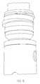
- FIG. 1is a perspective view of the helical backup element as disclosed herein;
- FIG. 2is a side view of the helical backup element disclosed herein disposed adjacent to primary sealing elements on a downhole tool;
- FIG. 3is an elevation view of the helical backup element as disclosed herein in an axially compressed state adjacent to the primary seal to illustrate action of the helical backup element.
- a tubular form backup element 10is represented having a helical opening 12 extending the length thereof.
- the helical opening 12creates individual turns 14 of material that may have either a fixed width (but for the end cuts which are orthogonal to the axis of the device thereby necessarily causing the turns to reduce in width) as illustrated in FIG. 1 or may be of varying width along the axial length of the backup element 10 .
- Exemplary full widths for the element 10are from about 1 ⁇ 8 inch to about 3 ⁇ 4 inch, in one embodiment. While some embodiments require limitation to the foregoing range, such limitation does not apply to all embodiments. As illustrated, only about two of the turns of the element 10 are full width.
- end cuts 16 and 18will each have faces that are not orthogonal to the axis of the element 10 but rather are frustoconically angled faces. Such angular faces will assist, in some embodiments, with radially outward movement of the element 10 .
- the element 10in one embodiment, comprises a composite material and binder.
- the materialrequires properties of structural integrity with relatively high tensile and shear resistance.
- the binderis to be selected to have sufficient cohesive strength and to be resistant to temperature, pressure and caustic fluids to stay intact while in the downhole environment. Examples of composites that meet the foregoing requirements are epoxy, phenolic, vinylester or other binders with carbon, aramid, glass, ceramic or other reinforcement and combinations including at least one of the foregoing. Choice of binder and reinforcement is tailored to the target application: temperature, pressure and chemical nature of the use-environment. It is to be appreciated that this is not an exhaustive list.
- the element 10appears as it does in FIG. 3 .
- the overall outside dimension of element 10is greater when the element is under axial compression (as illustrated in FIG. 3 ) than it is when not axially loaded, as in FIG. 2 .
- Careful consideration of the distinction in overall outside dimension of element 10 in FIG. 2 and FIG. 3will make this apparent to one of ordinary skill in the art.
- the outside dimension growth of element 10is due primarily to two major initiators. The first is the helical configuration of element 10 .
- each turn 14Upon axial compression element 10 , the helical surfaces at the sides of each turn 14 will tend to slip past one another in an unwinding direction relative to element 10 .
- element 10is caused to ride up on at least one frustoconical surface, illustrated with two surfaces 30 and 32 in FIG. 2 . Such surfaces will quite clearly urge element 10 in a radially outward direction and due to the helical nature of element 10 , resistance to such radially outwardly directed motion is minimal.
- the overall intent for element 10is indeed to grow an outside dimension thereby occupying the annular space 34 between the downhole tool (see 36 for example in FIG. 2 ) and a tubular member 38 within which the downhole tool 36 is to be installed. Because the composite materials indicated above are more rigid than the types of materials of the prior art that are usable through resilience, the element 10 provides superior extrusion resistance under all conditions.
Landscapes
- Life Sciences & Earth Sciences (AREA)
- Engineering & Computer Science (AREA)
- Geology (AREA)
- Mining & Mineral Resources (AREA)
- Physics & Mathematics (AREA)
- Environmental & Geological Engineering (AREA)
- Fluid Mechanics (AREA)
- General Life Sciences & Earth Sciences (AREA)
- Geochemistry & Mineralogy (AREA)
- Gasket Seals (AREA)
Abstract
Description
Claims (12)
Priority Applications (1)
| Application Number | Priority Date | Filing Date | Title |
|---|---|---|---|
| US12/123,073US8016295B2 (en) | 2007-06-05 | 2008-05-19 | Helical backup element |
Applications Claiming Priority (2)
| Application Number | Priority Date | Filing Date | Title |
|---|---|---|---|
| US94208407P | 2007-06-05 | 2007-06-05 | |
| US12/123,073US8016295B2 (en) | 2007-06-05 | 2008-05-19 | Helical backup element |
Publications (2)
| Publication Number | Publication Date |
|---|---|
| US20090126925A1 US20090126925A1 (en) | 2009-05-21 |
| US8016295B2true US8016295B2 (en) | 2011-09-13 |
Family
ID=40640720
Family Applications (1)
| Application Number | Title | Priority Date | Filing Date |
|---|---|---|---|
| US12/123,073Active2028-11-22US8016295B2 (en) | 2007-06-05 | 2008-05-19 | Helical backup element |
Country Status (1)
| Country | Link |
|---|---|
| US (1) | US8016295B2 (en) |
Cited By (30)
| Publication number | Priority date | Publication date | Assignee | Title |
|---|---|---|---|---|
| US20110272890A1 (en)* | 2010-05-04 | 2011-11-10 | Rolls-Royce Plc | Fireseal |
| US8839874B2 (en) | 2012-05-15 | 2014-09-23 | Baker Hughes Incorporated | Packing element backup system |
| US8905149B2 (en) | 2011-06-08 | 2014-12-09 | Baker Hughes Incorporated | Expandable seal with conforming ribs |
| US8955606B2 (en) | 2011-06-03 | 2015-02-17 | Baker Hughes Incorporated | Sealing devices for sealing inner wall surfaces of a wellbore and methods of installing same in a wellbore |
| US8955605B2 (en) | 2011-08-22 | 2015-02-17 | National Boss Hog Energy Services, Llc | Downhole tool and method of use |
| US9243490B2 (en) | 2012-12-19 | 2016-01-26 | Baker Hughes Incorporated | Electronically set and retrievable isolation devices for wellbores and methods thereof |
| US9260936B1 (en)* | 2009-12-04 | 2016-02-16 | Christopher A. Branton | Downhole bridge plug or packer assemblies |
| US20160123100A1 (en)* | 2014-10-30 | 2016-05-05 | Schlumberger Technology Corporation | Angled segmented backup ring |
| US9567827B2 (en) | 2013-07-15 | 2017-02-14 | Downhole Technology, Llc | Downhole tool and method of use |
| US9777551B2 (en) | 2011-08-22 | 2017-10-03 | Downhole Technology, Llc | Downhole system for isolating sections of a wellbore |
| US9784066B1 (en) | 2015-07-09 | 2017-10-10 | Christopher A. Branton | Downhole bridge plug or packer assemblies |
| US20180016864A1 (en)* | 2015-04-23 | 2018-01-18 | Baker Hughes, A Ge Company, Llc | Borehole plug with spiral cut slip and integrated sealing element |
| US9896899B2 (en) | 2013-08-12 | 2018-02-20 | Downhole Technology, Llc | Downhole tool with rounded mandrel |
| US9970256B2 (en) | 2015-04-17 | 2018-05-15 | Downhole Technology, Llc | Downhole tool and system, and method of use |
| US10024126B2 (en)* | 2011-08-22 | 2018-07-17 | Downhole Technology, Llc | Downhole tool and method of use |
| US10246967B2 (en) | 2011-08-22 | 2019-04-02 | Downhole Technology, Llc | Downhole system for use in a wellbore and method for the same |
| US10309189B1 (en) | 2016-03-24 | 2019-06-04 | Christopher A. Branton | Downhole bridge plugs reinforcing rings and reinforcing ring fabrication methods |
| US10316617B2 (en) | 2011-08-22 | 2019-06-11 | Downhole Technology, Llc | Downhole tool and system, and method of use |
| US10480267B2 (en) | 2016-11-17 | 2019-11-19 | The Wellboss Company, Llc | Downhole tool and method of use |
| US10570694B2 (en) | 2011-08-22 | 2020-02-25 | The Wellboss Company, Llc | Downhole tool and method of use |
| US10626696B1 (en) | 2017-03-23 | 2020-04-21 | Christopher A. Branton | Fluid-sealing downhole bridge plugs |
| US10633534B2 (en) | 2016-07-05 | 2020-04-28 | The Wellboss Company, Llc | Downhole tool and methods of use |
| US10801298B2 (en) | 2018-04-23 | 2020-10-13 | The Wellboss Company, Llc | Downhole tool with tethered ball |
| US10961796B2 (en) | 2018-09-12 | 2021-03-30 | The Wellboss Company, Llc | Setting tool assembly |
| US11078739B2 (en) | 2018-04-12 | 2021-08-03 | The Wellboss Company, Llc | Downhole tool with bottom composite slip |
| US11136852B2 (en) | 2019-01-09 | 2021-10-05 | Christopher A. Branton | Downhole bridge plug sealing element systems |
| WO2023014349A1 (en)* | 2021-08-03 | 2023-02-09 | Halliburton Energy Services, Inc. | Slip ring employing radially offset slot |
| US11634965B2 (en) | 2019-10-16 | 2023-04-25 | The Wellboss Company, Llc | Downhole tool and method of use |
| US11713645B2 (en) | 2019-10-16 | 2023-08-01 | The Wellboss Company, Llc | Downhole setting system for use in a wellbore |
| GB2622332A (en)* | 2021-08-03 | 2024-03-13 | Halliburton Energy Services Inc | Slip ring employing radially offset slot |
Families Citing this family (8)
| Publication number | Priority date | Publication date | Assignee | Title |
|---|---|---|---|---|
| US8307891B2 (en)* | 2009-01-28 | 2012-11-13 | Baker Hughes Incorporated | Retractable downhole backup assembly for circumferential seal support |
| US7806177B2 (en)* | 2009-01-28 | 2010-10-05 | Baker Hughes Incorporated | Retractable downhole backup assembly for circumferential seal support |
| US9228411B2 (en)* | 2010-10-06 | 2016-01-05 | Packers Plus Energy Services Inc. | Wellbore packer back-up ring assembly, packer and method |
| WO2018056951A1 (en)* | 2016-09-20 | 2018-03-29 | Halliburton Energy Services, Inc. | High expansion metal back-up ring for packers and bridge plugs |
| US11401762B2 (en)* | 2020-03-24 | 2022-08-02 | Ronald van Petegem | Roll-out apparatus, method, and system |
| WO2021217332A1 (en)* | 2020-04-27 | 2021-11-04 | 四川维泰科创石油设备制造有限公司 | Anchoring assembly for downhole tool, and downhole tool |
| US11713640B2 (en)* | 2020-10-23 | 2023-08-01 | Halliburton Energy Services, Inc. | Spiral backup ring containment for packer assemblies |
| US11732546B1 (en)* | 2022-11-30 | 2023-08-22 | Vertechs Oil & Gas Technology Co., Ltd. | Ultra-high expansion downhole packer |
Citations (15)
| Publication number | Priority date | Publication date | Assignee | Title |
|---|---|---|---|---|
| US485407A (en)* | 1892-11-01 | Frank k ethridge | ||
| US563445A (en)* | 1896-07-07 | Metallic packing | ||
| US567233A (en)* | 1896-09-08 | Antifriction packing | ||
| US1161851A (en)* | 1915-04-27 | 1915-11-30 | Keystone Driller Co | Valve for deep-well pumps. |
| US1991893A (en)* | 1934-03-28 | 1935-02-19 | Zeno E Flick | Metallic packing |
| US2749193A (en)* | 1952-04-24 | 1956-06-05 | Douglas Aircraft Co Inc | Back up washer |
| US2776154A (en)* | 1952-12-30 | 1957-01-01 | Johns Manville | Plastic packing |
| US2809080A (en)* | 1953-11-23 | 1957-10-08 | North American Aviation Inc | Anti-extrusion device for annular seals |
| US4239245A (en)* | 1979-12-07 | 1980-12-16 | A. W. Chesterton Company | Packing seals and method of making |
| US4431197A (en)* | 1980-05-19 | 1984-02-14 | Fibre-Wound (Pty) Limited | O-Ring gaskets and method of manufacturing same |
| US5123662A (en)* | 1989-09-22 | 1992-06-23 | Nobuyuki Sugimura | O-ring mounting groove and backup ring |
| US5311938A (en) | 1992-05-15 | 1994-05-17 | Halliburton Company | Retrievable packer for high temperature, high pressure service |
| US6651738B1 (en) | 2002-05-29 | 2003-11-25 | Baker Hughes Incoporated | Downhole isolation device with retained valve member |
| US6712153B2 (en) | 2001-06-27 | 2004-03-30 | Weatherford/Lamb, Inc. | Resin impregnated continuous fiber plug with non-metallic element system |
| US6796376B2 (en) | 2002-07-02 | 2004-09-28 | Warren L. Frazier | Composite bridge plug system |
- 2008
- 2008-05-19USUS12/123,073patent/US8016295B2/enactiveActive
Patent Citations (15)
| Publication number | Priority date | Publication date | Assignee | Title |
|---|---|---|---|---|
| US485407A (en)* | 1892-11-01 | Frank k ethridge | ||
| US563445A (en)* | 1896-07-07 | Metallic packing | ||
| US567233A (en)* | 1896-09-08 | Antifriction packing | ||
| US1161851A (en)* | 1915-04-27 | 1915-11-30 | Keystone Driller Co | Valve for deep-well pumps. |
| US1991893A (en)* | 1934-03-28 | 1935-02-19 | Zeno E Flick | Metallic packing |
| US2749193A (en)* | 1952-04-24 | 1956-06-05 | Douglas Aircraft Co Inc | Back up washer |
| US2776154A (en)* | 1952-12-30 | 1957-01-01 | Johns Manville | Plastic packing |
| US2809080A (en)* | 1953-11-23 | 1957-10-08 | North American Aviation Inc | Anti-extrusion device for annular seals |
| US4239245A (en)* | 1979-12-07 | 1980-12-16 | A. W. Chesterton Company | Packing seals and method of making |
| US4431197A (en)* | 1980-05-19 | 1984-02-14 | Fibre-Wound (Pty) Limited | O-Ring gaskets and method of manufacturing same |
| US5123662A (en)* | 1989-09-22 | 1992-06-23 | Nobuyuki Sugimura | O-ring mounting groove and backup ring |
| US5311938A (en) | 1992-05-15 | 1994-05-17 | Halliburton Company | Retrievable packer for high temperature, high pressure service |
| US6712153B2 (en) | 2001-06-27 | 2004-03-30 | Weatherford/Lamb, Inc. | Resin impregnated continuous fiber plug with non-metallic element system |
| US6651738B1 (en) | 2002-05-29 | 2003-11-25 | Baker Hughes Incoporated | Downhole isolation device with retained valve member |
| US6796376B2 (en) | 2002-07-02 | 2004-09-28 | Warren L. Frazier | Composite bridge plug system |
Non-Patent Citations (1)
| Title |
|---|
| Guoynes, J.C.; "New Composite Fracturing Plug Improves Efficiency in Coalbed Methane Completions". Halliburton Energy Services, Inc.; SPE 40052. Apr. 5-8, 1998. pp. 603-613. |
Cited By (63)
| Publication number | Priority date | Publication date | Assignee | Title |
|---|---|---|---|---|
| US9260936B1 (en)* | 2009-12-04 | 2016-02-16 | Christopher A. Branton | Downhole bridge plug or packer assemblies |
| US20110272890A1 (en)* | 2010-05-04 | 2011-11-10 | Rolls-Royce Plc | Fireseal |
| US8955606B2 (en) | 2011-06-03 | 2015-02-17 | Baker Hughes Incorporated | Sealing devices for sealing inner wall surfaces of a wellbore and methods of installing same in a wellbore |
| US8905149B2 (en) | 2011-06-08 | 2014-12-09 | Baker Hughes Incorporated | Expandable seal with conforming ribs |
| US10024126B2 (en)* | 2011-08-22 | 2018-07-17 | Downhole Technology, Llc | Downhole tool and method of use |
| US10605020B2 (en)* | 2011-08-22 | 2020-03-31 | The Wellboss Company, Llc | Downhole tool and method of use |
| US9010411B1 (en) | 2011-08-22 | 2015-04-21 | National Boss Hog Energy Services Llc | Downhole tool and method of use |
| US9074439B2 (en) | 2011-08-22 | 2015-07-07 | National Boss Hog Energy Services Llc | Downhole tool and method of use |
| US9097095B2 (en) | 2011-08-22 | 2015-08-04 | National Boss Hog Energy Services, Llc | Downhole tool and method of use |
| US9103177B2 (en) | 2011-08-22 | 2015-08-11 | National Boss Hog Energy Services, Llc | Downhole tool and method of use |
| US20150260007A1 (en)* | 2011-08-22 | 2015-09-17 | National Boss Hog Energy Services, Llc | Downhole tool and method of use |
| US11136855B2 (en) | 2011-08-22 | 2021-10-05 | The Wellboss Company, Llc | Downhole tool with a slip insert having a hole |
| US8955605B2 (en) | 2011-08-22 | 2015-02-17 | National Boss Hog Energy Services, Llc | Downhole tool and method of use |
| US9316086B2 (en)* | 2011-08-22 | 2016-04-19 | National Boss Hog Energy Services, Llc | Downhole tool and method of use |
| US11008827B2 (en) | 2011-08-22 | 2021-05-18 | The Wellboss Company, Llc | Downhole plugging system |
| US9334703B2 (en) | 2011-08-22 | 2016-05-10 | Downhole Technology, Llc | Downhole tool having an anti-rotation configuration and method for using the same |
| US9562416B2 (en) | 2011-08-22 | 2017-02-07 | Downhole Technology, Llc | Downhole tool with one-piece slip |
| US10900321B2 (en) | 2011-08-22 | 2021-01-26 | The Wellboss Company, Llc | Downhole tool and method of use |
| US9631453B2 (en) | 2011-08-22 | 2017-04-25 | Downhole Technology, Llc | Downhole tool and method of use |
| US9689228B2 (en) | 2011-08-22 | 2017-06-27 | Downhole Technology, Llc | Downhole tool with one-piece slip |
| US9719320B2 (en) | 2011-08-22 | 2017-08-01 | Downhole Technology, Llc | Downhole tool with one-piece slip |
| US9725982B2 (en) | 2011-08-22 | 2017-08-08 | Downhole Technology, Llc | Composite slip for a downhole tool |
| US10246967B2 (en) | 2011-08-22 | 2019-04-02 | Downhole Technology, Llc | Downhole system for use in a wellbore and method for the same |
| US10214981B2 (en) | 2011-08-22 | 2019-02-26 | Downhole Technology, Llc | Fingered member for a downhole tool |
| US9777551B2 (en) | 2011-08-22 | 2017-10-03 | Downhole Technology, Llc | Downhole system for isolating sections of a wellbore |
| US10605044B2 (en)* | 2011-08-22 | 2020-03-31 | The Wellboss Company, Llc | Downhole tool with fingered member |
| US10570694B2 (en) | 2011-08-22 | 2020-02-25 | The Wellboss Company, Llc | Downhole tool and method of use |
| US10494895B2 (en) | 2011-08-22 | 2019-12-03 | The Wellboss Company, Llc | Downhole tool and method of use |
| US10480277B2 (en) | 2011-08-22 | 2019-11-19 | The Wellboss Company, Llc | Downhole tool and method of use |
| US9976382B2 (en) | 2011-08-22 | 2018-05-22 | Downhole Technology, Llc | Downhole tool and method of use |
| US10316617B2 (en) | 2011-08-22 | 2019-06-11 | Downhole Technology, Llc | Downhole tool and system, and method of use |
| US10036221B2 (en)* | 2011-08-22 | 2018-07-31 | Downhole Technology, Llc | Downhole tool and method of use |
| US8997853B2 (en) | 2011-08-22 | 2015-04-07 | National Boss Hog Energy Services, Llc | Downhole tool and method of use |
| US10156120B2 (en)* | 2011-08-22 | 2018-12-18 | Downhole Technology, Llc | System and method for downhole operations |
| US10711563B2 (en) | 2011-08-22 | 2020-07-14 | The Wellboss Company, Llc | Downhole tool having a mandrel with a relief point |
| US20190162032A1 (en)* | 2011-08-22 | 2019-05-30 | Downhole Technology, Llc | Downhole tool and method of use |
| US8839874B2 (en) | 2012-05-15 | 2014-09-23 | Baker Hughes Incorporated | Packing element backup system |
| US9243490B2 (en) | 2012-12-19 | 2016-01-26 | Baker Hughes Incorporated | Electronically set and retrievable isolation devices for wellbores and methods thereof |
| US9759029B2 (en)* | 2013-07-15 | 2017-09-12 | Downhole Technology, Llc | Downhole tool and method of use |
| US9567827B2 (en) | 2013-07-15 | 2017-02-14 | Downhole Technology, Llc | Downhole tool and method of use |
| US9896899B2 (en) | 2013-08-12 | 2018-02-20 | Downhole Technology, Llc | Downhole tool with rounded mandrel |
| US9739106B2 (en)* | 2014-10-30 | 2017-08-22 | Schlumberger Technology Corporation | Angled segmented backup ring |
| US20160123100A1 (en)* | 2014-10-30 | 2016-05-05 | Schlumberger Technology Corporation | Angled segmented backup ring |
| US9970256B2 (en) | 2015-04-17 | 2018-05-15 | Downhole Technology, Llc | Downhole tool and system, and method of use |
| US20180016864A1 (en)* | 2015-04-23 | 2018-01-18 | Baker Hughes, A Ge Company, Llc | Borehole plug with spiral cut slip and integrated sealing element |
| US9784066B1 (en) | 2015-07-09 | 2017-10-10 | Christopher A. Branton | Downhole bridge plug or packer assemblies |
| US10309189B1 (en) | 2016-03-24 | 2019-06-04 | Christopher A. Branton | Downhole bridge plugs reinforcing rings and reinforcing ring fabrication methods |
| US10633534B2 (en) | 2016-07-05 | 2020-04-28 | The Wellboss Company, Llc | Downhole tool and methods of use |
| US10480267B2 (en) | 2016-11-17 | 2019-11-19 | The Wellboss Company, Llc | Downhole tool and method of use |
| US10781659B2 (en) | 2016-11-17 | 2020-09-22 | The Wellboss Company, Llc | Fingered member with dissolving insert |
| US10907441B2 (en) | 2016-11-17 | 2021-02-02 | The Wellboss Company, Llc | Downhole tool and method of use |
| US10480280B2 (en) | 2016-11-17 | 2019-11-19 | The Wellboss Company, Llc | Downhole tool and method of use |
| US10626696B1 (en) | 2017-03-23 | 2020-04-21 | Christopher A. Branton | Fluid-sealing downhole bridge plugs |
| US11078739B2 (en) | 2018-04-12 | 2021-08-03 | The Wellboss Company, Llc | Downhole tool with bottom composite slip |
| US11634958B2 (en) | 2018-04-12 | 2023-04-25 | The Wellboss Company, Llc | Downhole tool with bottom composite slip |
| US10801298B2 (en) | 2018-04-23 | 2020-10-13 | The Wellboss Company, Llc | Downhole tool with tethered ball |
| US10961796B2 (en) | 2018-09-12 | 2021-03-30 | The Wellboss Company, Llc | Setting tool assembly |
| US11136852B2 (en) | 2019-01-09 | 2021-10-05 | Christopher A. Branton | Downhole bridge plug sealing element systems |
| US11555374B2 (en) | 2019-01-09 | 2023-01-17 | Christopher A. Branton | Backup rings for downhole bridge plug sealing element systems |
| US11634965B2 (en) | 2019-10-16 | 2023-04-25 | The Wellboss Company, Llc | Downhole tool and method of use |
| US11713645B2 (en) | 2019-10-16 | 2023-08-01 | The Wellboss Company, Llc | Downhole setting system for use in a wellbore |
| WO2023014349A1 (en)* | 2021-08-03 | 2023-02-09 | Halliburton Energy Services, Inc. | Slip ring employing radially offset slot |
| GB2622332A (en)* | 2021-08-03 | 2024-03-13 | Halliburton Energy Services Inc | Slip ring employing radially offset slot |
Also Published As
| Publication number | Publication date |
|---|---|
| US20090126925A1 (en) | 2009-05-21 |
Similar Documents
| Publication | Publication Date | Title |
|---|---|---|
| US8016295B2 (en) | Helical backup element | |
| US5749585A (en) | Downhole tool sealing system with cylindrical biasing member with narrow width and wider width openings | |
| RU2550612C2 (en) | Circular web | |
| AU2012249597B2 (en) | Expandable open-hole anchor | |
| EP1753936B1 (en) | Sealing system | |
| US8555961B2 (en) | Swellable packer with composite material end rings | |
| CA2300622C (en) | Steep pitch helix packer | |
| US9133681B2 (en) | Protected retaining bands | |
| MX2013013823A (en) | An annular barrier with external seal. | |
| US9568120B2 (en) | Flush joint pipe | |
| US20090242215A1 (en) | System and method for packing | |
| US8550178B2 (en) | Expandable isolation packer | |
| US8281854B2 (en) | Connector for mounting screen to base pipe without welding or swaging | |
| EP3099894B1 (en) | Splicable fiber optic sensing system, method of making same and tape for sense transmissively locking an optical fiber | |
| US20090200042A1 (en) | Radially supported seal and method | |
| US20090283256A1 (en) | Downhole tubular length compensating system and method | |
| US20080230236A1 (en) | Packing element and method | |
| US9540899B1 (en) | Downhole seal apparatus and method thereof | |
| US11808103B2 (en) | Swellable packer assembly for a wellbore system | |
| US10047574B2 (en) | Centralizer and associated devices | |
| WO2012084888A1 (en) | System and method for providing a pressure seal | |
| US20230265737A1 (en) | High expansion backup, seal, and system | |
| US10208550B2 (en) | Anchoring device, system and method of attaching an anchor to a tubular | |
| AU2018202100A1 (en) | Downhole apparatus and method | |
| EP2469016A1 (en) | System and method for sealing a space in a wellbore |
Legal Events
| Date | Code | Title | Description |
|---|---|---|---|
| AS | Assignment | Owner name:BAKER HUGHES INCORPORATED, TEXAS Free format text:ASSIGNMENT OF ASSIGNORS INTEREST;ASSIGNORS:GUEST, RANDALL V.;SAMUELSON, MARC N.;VINSON, JUSTIN P.;AND OTHERS;REEL/FRAME:021093/0092;SIGNING DATES FROM 20080523 TO 20080527 Owner name:BAKER HUGHES INCORPORATED, TEXAS Free format text:ASSIGNMENT OF ASSIGNORS INTEREST;ASSIGNORS:GUEST, RANDALL V.;SAMUELSON, MARC N.;VINSON, JUSTIN P.;AND OTHERS;SIGNING DATES FROM 20080523 TO 20080527;REEL/FRAME:021093/0092 | |
| STCF | Information on status: patent grant | Free format text:PATENTED CASE | |
| FPAY | Fee payment | Year of fee payment:4 | |
| MAFP | Maintenance fee payment | Free format text:PAYMENT OF MAINTENANCE FEE, 8TH YEAR, LARGE ENTITY (ORIGINAL EVENT CODE: M1552); ENTITY STATUS OF PATENT OWNER: LARGE ENTITY Year of fee payment:8 | |
| AS | Assignment | Owner name:BAKER HUGHES, A GE COMPANY, LLC, TEXAS Free format text:CHANGE OF NAME;ASSIGNOR:BAKER HUGHES INCORPORATED;REEL/FRAME:059480/0512 Effective date:20170703 | |
| AS | Assignment | Owner name:BAKER HUGHES HOLDINGS LLC, TEXAS Free format text:CHANGE OF NAME;ASSIGNOR:BAKER HUGHES, A GE COMPANY, LLC;REEL/FRAME:059595/0759 Effective date:20200413 | |
| MAFP | Maintenance fee payment | Free format text:PAYMENT OF MAINTENANCE FEE, 12TH YEAR, LARGE ENTITY (ORIGINAL EVENT CODE: M1553); ENTITY STATUS OF PATENT OWNER: LARGE ENTITY Year of fee payment:12 |