US8016220B2 - Mill liner assembly - Google Patents
Mill liner assemblyDownload PDFInfo
- Publication number
- US8016220B2 US8016220B2US11/795,654US79565406AUS8016220B2US 8016220 B2US8016220 B2US 8016220B2US 79565406 AUS79565406 AUS 79565406AUS 8016220 B2US8016220 B2US 8016220B2
- Authority
- US
- United States
- Prior art keywords
- wall
- liner assembly
- cushioning member
- elastomeric cushioning
- wear elements
- Prior art date
- Legal status (The legal status is an assumption and is not a legal conclusion. Google has not performed a legal analysis and makes no representation as to the accuracy of the status listed.)
- Expired - Fee Related
Links
- 230000000712assemblyEffects0.000claimsdescription9
- 238000000429assemblyMethods0.000claimsdescription9
- 239000013536elastomeric materialSubstances0.000claimsdescription2
- 239000000463materialSubstances0.000description11
- 230000001681protective effectEffects0.000description6
- 239000002184metalSubstances0.000description3
- 238000010276constructionMethods0.000description2
- 229910052500inorganic mineralInorganic materials0.000description2
- 239000011707mineralSubstances0.000description2
- 238000005299abrasionMethods0.000description1
- 238000007792additionMethods0.000description1
- 230000004075alterationEffects0.000description1
- 239000000919ceramicSubstances0.000description1
- 230000005484gravityEffects0.000description1
- 229910001092metal group alloyInorganic materials0.000description1
- 238000012986modificationMethods0.000description1
- 230000004048modificationEffects0.000description1
- 239000011435rockSubstances0.000description1
- 229920002994synthetic fiberPolymers0.000description1
Images


Classifications
- B—PERFORMING OPERATIONS; TRANSPORTING
- B02—CRUSHING, PULVERISING, OR DISINTEGRATING; PREPARATORY TREATMENT OF GRAIN FOR MILLING
- B02C—CRUSHING, PULVERISING, OR DISINTEGRATING IN GENERAL; MILLING GRAIN
- B02C17/00—Disintegrating by tumbling mills, i.e. mills having a container charged with the material to be disintegrated with or without special disintegrating members such as pebbles or balls
- B02C17/18—Details
- B02C17/22—Lining for containers
Definitions
- the present inventionrelates generally to the crushing, grinding, comminuting or similarly processing materials such as mineral ores, rock and other materials, and more particularly to apparatus for use in such processing.
- sulphurated mineralsare processed to produce particulated matter of a size between 100 and 20 microns.
- Grinding millsare one form of apparatus used for processing materials as described above.
- Typical grinding millsgenerally comprise a drum shaped shell mounted for rotation about its central axis.
- the axis of the shellis generally horizontally disposed or slightly inclined towards one end.
- the interior of the shellforms a treatment chamber into which the material to be processed is fed.
- a grinding mediumsuch as balls or rods is fed to the treatment chamber with the material to be processed.
- the grinding mediumacts on the material to cause the crushing or grinding action.
- the aspect ratio of the mill diameter to the mill lengthis ⁇ 1 and >1 respectively.
- the grinding medium and material to be processedare carried up the side of the shell as a result of the centrifugal force created by rotation of the shell whereafter it falls towards the bottom of the shell under the influence of gravity.
- lifter barsare often provided which are secured to the interior surface of the shell.
- the lifter barsextend generally longitudinally of the shell and are circumferentially spaced apart around the inner surface. The higher the material travels up the shell the better the grinding of the material. Examples of such mils are described in Chilean Patents 39450 and 36411.
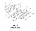
- FIG. 1is a partial schematic illustration of a typical grinding mill having a shell 10 with a plurality of lifter bars 12 mounted to the inner surface of the shell 10 .
- the lifter bars 12are circumferentially spaced apart around the inner surface of the shell 10 and extend in the direction of the axis of rotation of the shell.
- the spaces between adjacent lifter bars 12form channels 14 of width J.
- the length of the bars 12is shown as LM which is the inner length of the shell in the direction of rotation thereof.
- the number of channels 14is the same as the number of lifter bars 12 .
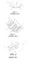
- FIGS. 2 to 4are various illustrations of conventional liner assemblies adapted to be installed in a mill as shown in FIG. 1 .
- each channel 14is adapted to have mounted therein a liner assembly 20 .
- the conventional liner assembly 20includes a metal base member 22 which is adapted to be mounted to the inner surface of the shell by suitable fastenings such as bolts (not shown).
- the base member 22includes an elongated plate having mounting elements 23 thereon.
- the liner assemblyfurther includes a generally flat wear element 24 which is mounted to the base member 22 .
- the wear element 24may be formed of an elastomeric material or metal for providing protection against abrasion and impact. Because of the constant impact forces applied to the wear elements when the mill is in operation, they will tend to break after a period of time. When breakage occurs the mill needs to be stopped while they are replaced. This can be time consuming and reduce the overall productivity of the mill.
- a liner assemblyfor use in a grinding mill, the liner assembly including a liner body including a mounting member, an elastomeric cushioning member operatively connected to the mounting member, said cushioning member including a plurality of support cavities therein, and a plurality of wear elements mounted within the support cavities.
- the liner assembly according to the present inventionis suitable for a use which includes a rotatable shell having a plurality of lifter bars on the inner surface thereof, the lifter bars extending generally in the same direction as the axis of rotation of the shell.
- the lifter barsare circumferentially spaced apart around the inner surface of the shell so as to form channels therebetween.
- the liner assembliesare disposed within the channels with the mounting members secured to the inner surface of the shell.
- the cushioning membermay be an elongated body having the cavities arranged in a row extending in the longitudinal direction of the elongated body. Two or more rows of cavities may be arranged side by side. In one form, the cavities in one row may be offset with respect to cavities in an adjacent row. The length of the cushioning member may be between 2 to 12 times the width of the member.
- the liner bodymay include a base wall, opposed side walls extending away from the base wall and terminating at an outer edge, and an outer wall extending from the outer edge of the side walls.
- the distance K from the base wall to the outer edge of the side wallsmay be about the width of the lifting bar.
- the distance M from the outer edge of the side walls to an outermost region of the outer wallmay be about 1 to 40 cm.
- the cavitiesmay include a lower wall and the distance S from the base wall of the liner body to the lower wall of the cavities may be from 0.1 K to 0.9 K where K is the distance from the base wall to the outer edge of the side walls of the liner body.
- the elastomeric cushionmay have a Shore hardness between 30 to 85 hardness Shore A.
- Adjacent cavities in a rowmay be separated by a wall having a thickness from about 0.5 mm to 20 mm.
- the wear elementsmay be generally polyhedric in shape.
- the wear elementsmay have a Brinell hardness of between 350 to 800 BHN.
- the outer surface of the outer wall of the liner bodyis substantially defined by an outer surface of the wear elements.
- the side walls of the bodymay be slightly inclined towards one another.
- FIG. 1is a partial cross-section of an axonometric view of a mill without protective liners
- FIG. 2is a partial view of an elevated cross-section perpendicular to the axis of the mill with conventional protective liner assemblies;
- FIG. 3is a partial cross-section of an axonometric view of a mill with conventional protective liner assemblies
- FIG. 4illustrates the features of a conventional protective liner assembly
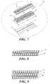
- FIG. 5is a partial cross-section of an axonometric view of a mill with protective liner assemblies according to the present invention
- FIG. 6is a partial view of an elevated cross-section perpendicular to the axis of the mill with liner assemblies according to the present invention.
- FIG. 7is a view of the protective liner assembly according to the present invention.
- FIG. 8is a plan view of a preferred form of wear element of the liner assembly of the present invention.
- FIG. 9is a plan view of another preferred form of wear element of the liner assembly of the present invention.
- FIGS. 10 , 11 , 12 , 13 , 14 , 15 and 16are different configurations of the wear element and the surface exposed to the impact of the apparatus according to the present invention.
- FIG. 1A partial view of a typical grinding mill is shown in FIG. 1 having conventional liner assemblies has as been described earlier with reference to FIGS. 2 to 4 .
- FIG. 5is a partial schematic illustration of a grinding mill with liner assemblies according to the present invention.
- the millhas a shell 10 with a plurality of lifter bars 12 mounted to the inner surface of the shell 10 .
- the lifter bars 12are circumferentially spaced apart around the inner surface of the shell 10 and extend in the direction of the axis of rotation of the shell.
- the spaces between adjacent lifter bars 12form channels 14 of width J.
- the length of the bars 12is shown as LM which is the inner length of the shell in the direction of rotation thereof.
- the number of channels 14is the same as the number of lifter bars 12 .
- Each channel 14is adapted to have mounted therein a liner assembly 30 in accordance with the present invention as shown in FIG. 7 .
- the liner assembly 30includes a base member 32 which is adapted to be mounted to the inner surface of the shell by suitable fastenings such as bolts (not shown).
- the base member 32includes an elongated plate having mounting elements 33 thereon.
- the liner assemblyfurther includes an elastomeric cushioning member 34 which is secured to the base member 32 .
- the cushioning member 34has a plurality of cavities 36 therein for receiving wear elements 40 .
- the width of the liner assemblyis about the same as the width of the channels 14 between adjacent lifter bars 12 and the length of the liner assembly is between 2 and 12 times the width of the member.
- the liner assembly 30has a base wall having an underside which substantially conforms to the curvature of the inner surface of the shell and side walls extending from the base wall and being of a height K which is approximately the same as the height of the side walls of the lifter bars 14 .
- the wear elementsare arranged in two rows 44 and 45 in which the elements are offset from one another.
- FIG. 9three rows 44 , 45 and 46 are shown with the elements in adjacent rows being offset from one another.
- the wear elementsmay be formed from metal, a metal alloy, ceramic or any other suitable material.
- the wear elementspreferably have a Brinell hardness between 350 and 800 BHN.
- the cushioning membermay be a natural or synthetic material or a combination of both with a Shore hardness between 30 to 85 hardness Shore A.
- FIGS. 10 to 16illustrate in cross section various configurations and shapes of the cushioning member and wear elements.
- FIGS. 10 , 13 , 14 , 15 and 16show a single row of wear elements 40 of different cross sectional shapes.
- FIG. 11illustrates an arrangement with two rows of wear elements 40 and
- FIG. 12illustrates three rows of wear elements.
Landscapes
- Engineering & Computer Science (AREA)
- Food Science & Technology (AREA)
- Crushing And Grinding (AREA)
- Food-Manufacturing Devices (AREA)
- Crushing And Pulverization Processes (AREA)
- Milling Processes (AREA)
- Polishing Bodies And Polishing Tools (AREA)
- Finish Polishing, Edge Sharpening, And Grinding By Specific Grinding Devices (AREA)
Abstract
Description
Claims (14)
Applications Claiming Priority (3)
| Application Number | Priority Date | Filing Date | Title |
|---|---|---|---|
| CL2005000102 | 2005-01-18 | ||
| CL0102-2005 | 2005-01-18 | ||
| PCT/AU2006/000049WO2006076764A1 (en) | 2005-01-18 | 2006-01-16 | Mill liner assembly |
Publications (2)
| Publication Number | Publication Date |
|---|---|
| US20080265074A1 US20080265074A1 (en) | 2008-10-30 |
| US8016220B2true US8016220B2 (en) | 2011-09-13 |
Family
ID=40279086
Family Applications (1)
| Application Number | Title | Priority Date | Filing Date |
|---|---|---|---|
| US11/795,654Expired - Fee RelatedUS8016220B2 (en) | 2005-01-18 | 2006-01-16 | Mill liner assembly |
Country Status (14)
| Country | Link |
|---|---|
| US (1) | US8016220B2 (en) |
| EP (1) | EP1838446B1 (en) |
| CN (1) | CN101107076B (en) |
| AP (1) | AP2330A (en) |
| AR (1) | AR052461A1 (en) |
| AU (1) | AU2006207815B2 (en) |
| CA (1) | CA2595002C (en) |
| EA (1) | EA010217B1 (en) |
| MA (1) | MA28067A1 (en) |
| MX (1) | MX2007008735A (en) |
| NZ (1) | NZ556308A (en) |
| PE (1) | PE20061001A1 (en) |
| WO (1) | WO2006076764A1 (en) |
| ZA (1) | ZA200705522B (en) |
Cited By (8)
| Publication number | Priority date | Publication date | Assignee | Title |
|---|---|---|---|---|
| US20150110592A1 (en)* | 2013-10-17 | 2015-04-23 | Harnischfeger Technologies, Inc. | Liner system for a dipper |
| US20150224509A1 (en)* | 2014-02-12 | 2015-08-13 | Kennametal Inc. | Grain mill liner assembly |
| US20160067715A1 (en)* | 2013-04-15 | 2016-03-10 | Outotec (Finland) Oy | A method of making a lifter bar, a refurbished lifter bar and a mould |
| US9475057B2 (en) | 2013-01-24 | 2016-10-25 | Cabot Corporation | Liner elements with improved wear-life for grinding operations |
| US10933424B1 (en) | 2019-12-11 | 2021-03-02 | Pearson Incorporated | Grinding roll improvements |
| US20220062913A1 (en)* | 2018-12-11 | 2022-03-03 | Orbis Mining Pty Ltd. | Crushing of core samples |
| US11534770B1 (en) | 2017-07-26 | 2022-12-27 | Pearson Incorporated | Systems and methods for step grinding |
| US11751507B1 (en) | 2019-10-31 | 2023-09-12 | Hemp Processing Solutions, LLC | Crop harvesting system with plant stripping apparatus |
Families Citing this family (20)
| Publication number | Priority date | Publication date | Assignee | Title |
|---|---|---|---|---|
| PE20110649A1 (en)* | 2008-08-11 | 2011-09-17 | Weir Minerals Australia Ltd | METHOD OF MANUFACTURING A COATING COMPONENT FOR A GRINDING MILL |
| AU2013204268B2 (en)* | 2009-09-25 | 2014-06-26 | WHW Group, Inc. | Mill liner for a grinding mill |
| PE20130050A1 (en)* | 2009-09-25 | 2013-02-04 | Weir Slurry Group Inc | COATING FOR A MILL |
| CA2796097C (en)* | 2010-04-19 | 2018-05-22 | Vulco S.A. | A wear plate system, arrangement and method |
| PE20130925A1 (en) | 2010-04-19 | 2013-09-14 | Vulco Sa | WEAR PLATE FIXING SYSTEM, ARRANGEMENT AND METHOD |
| CN101912804B (en)* | 2010-09-03 | 2012-07-25 | 华智节能(香港)有限公司 | Novel Liner Structure and Manufacturing Method for Tube Mill in Cement Industry |
| CN104056698A (en)* | 2014-06-27 | 2014-09-24 | 江西耐普矿机新材料股份有限公司 | Wear-resisting semi-autogenous mill composite lining plate |
| US10543985B2 (en)* | 2015-01-19 | 2020-01-28 | Flsmidth A/S | Interlocking wear-resistant panel system |
| USD773763S1 (en)* | 2015-02-24 | 2016-12-06 | Samsung Electronics Co., Ltd. | Drum lifter for drum washing machine |
| USD789630S1 (en)* | 2015-02-24 | 2017-06-13 | Samsung Electronics Co., Ltd. | Drum lifter for drum washing machine |
| USD889059S1 (en)* | 2018-10-30 | 2020-06-30 | Lg Electronics Inc. | Washing machine lifter |
| USD897618S1 (en)* | 2018-10-30 | 2020-09-29 | Lg Electronics Inc. | Washing machine drum lifter |
| USD923265S1 (en)* | 2019-07-19 | 2021-06-22 | Lg Electronics Inc. | Set of washing machine drum lifters |
| USD923266S1 (en)* | 2019-07-19 | 2021-06-22 | Lg Electronics Inc. | Set of washing machine drum lifters |
| USD923267S1 (en)* | 2019-07-19 | 2021-06-22 | Lg Electronics Inc. | Set of washing machine drum lifters |
| USD923264S1 (en)* | 2019-07-19 | 2021-06-22 | Lg Electronics Inc | Washing machine drum lifter |
| USD915699S1 (en)* | 2019-07-19 | 2021-04-06 | Lg Electronics Inc. | Washing machine drum lifter |
| USD917120S1 (en)* | 2019-07-19 | 2021-04-20 | Lg Electronics Inc. | Washing machine drum lifter |
| EP4281248A1 (en)* | 2021-01-22 | 2023-11-29 | Fravizel - Equipamentos Metalomecânicos, S.A. | A drum and an apparatus for the surface processing of rock or mosaic pieces through rotation |
| CN114308287B (en)* | 2021-12-30 | 2023-02-03 | 洛阳山盾机械科技有限公司 | Solve lining plate structure of autogenous mill and semi-autogenous mill deformation or fracture |
Citations (8)
| Publication number | Priority date | Publication date | Assignee | Title |
|---|---|---|---|---|
| US3107867A (en)* | 1961-02-25 | 1963-10-22 | Skelleftea Gummifabriks A G | Wear lining |
| US3607606A (en)* | 1967-05-16 | 1971-09-21 | Coors Porcelain Co | Ceramic-rubber composites |
| US3942239A (en)* | 1973-03-06 | 1976-03-09 | Skega Aktiebolag | Method of lining a steel structure |
| US4177955A (en)* | 1978-06-02 | 1979-12-11 | The B. F. Goodrich Company | Mill wear member |
| SU950436A1 (en) | 1980-12-17 | 1982-08-15 | Всесоюзный Научно-Исследовательский,Проектно-Конструкторский,Технологический Институт Механизации Труда В Черной Металлургии И Ремонтно-Механических Работ | Drum mill lining |
| SU1235527A1 (en) | 1985-01-15 | 1986-06-07 | Всесоюзный научно-исследовательский проектно-конструкторский технологический институт механизации труда в черной металлургии и ремонтно-механических работ | Lining of tumbling barrel |
| US5472148A (en)* | 1992-01-10 | 1995-12-05 | Envirotech Pumpsystems, Inc. | Grinding mill, lining and associated method of manufacture |
| US6510729B2 (en)* | 2000-11-06 | 2003-01-28 | Magotteaux International | Device for determining the corrosion of the grinding bodies in a rotary mill |
Family Cites Families (4)
| Publication number | Priority date | Publication date | Assignee | Title |
|---|---|---|---|---|
| GB1158565A (en)* | 1965-08-02 | 1969-07-16 | Skelleftea Gummifabriks A B | Improvements in or relating to a Wear Element |
| SU1235327A1 (en)* | 1983-06-15 | 1992-09-07 | Предприятие П/Я А-3603 | Method of graduating liquid transducer of parameters of acoustic and seismic fields method of determining effectiviness of radiation action on materials |
| SE503673C2 (en)* | 1994-11-30 | 1996-07-29 | Skega Ab | Grinding procedure and milling |
| CN2579519Y (en)* | 2002-11-18 | 2003-10-15 | 株洲市工业橡胶制品厂 | Mill tubular part rubber lining structure |
- 2006
- 2006-01-16PEPE2006000066Apatent/PE20061001A1/enactiveIP Right Grant
- 2006-01-16NZNZ556308Apatent/NZ556308A/ennot_activeIP Right Cessation
- 2006-01-16WOPCT/AU2006/000049patent/WO2006076764A1/enactiveApplication Filing
- 2006-01-16EPEP06700538.9Apatent/EP1838446B1/ennot_activeNot-in-force
- 2006-01-16APAP2007004074Apatent/AP2330A/enactive
- 2006-01-16MXMX2007008735Apatent/MX2007008735A/enactiveIP Right Grant
- 2006-01-16USUS11/795,654patent/US8016220B2/ennot_activeExpired - Fee Related
- 2006-01-16AUAU2006207815Apatent/AU2006207815B2/ennot_activeCeased
- 2006-01-16CACA2595002Apatent/CA2595002C/enactiveActive
- 2006-01-16CNCN2006800025661Apatent/CN101107076B/ennot_activeExpired - Fee Related
- 2006-01-16EAEA200701533Apatent/EA010217B1/ennot_activeIP Right Cessation
- 2006-01-17MAMA28733Apatent/MA28067A1/enunknown
- 2006-01-18ARARP060100193Apatent/AR052461A1/enactiveIP Right Grant
- 2007
- 2007-07-05ZAZA200705522Apatent/ZA200705522B/enunknown
Patent Citations (8)
| Publication number | Priority date | Publication date | Assignee | Title |
|---|---|---|---|---|
| US3107867A (en)* | 1961-02-25 | 1963-10-22 | Skelleftea Gummifabriks A G | Wear lining |
| US3607606A (en)* | 1967-05-16 | 1971-09-21 | Coors Porcelain Co | Ceramic-rubber composites |
| US3942239A (en)* | 1973-03-06 | 1976-03-09 | Skega Aktiebolag | Method of lining a steel structure |
| US4177955A (en)* | 1978-06-02 | 1979-12-11 | The B. F. Goodrich Company | Mill wear member |
| SU950436A1 (en) | 1980-12-17 | 1982-08-15 | Всесоюзный Научно-Исследовательский,Проектно-Конструкторский,Технологический Институт Механизации Труда В Черной Металлургии И Ремонтно-Механических Работ | Drum mill lining |
| SU1235527A1 (en) | 1985-01-15 | 1986-06-07 | Всесоюзный научно-исследовательский проектно-конструкторский технологический институт механизации труда в черной металлургии и ремонтно-механических работ | Lining of tumbling barrel |
| US5472148A (en)* | 1992-01-10 | 1995-12-05 | Envirotech Pumpsystems, Inc. | Grinding mill, lining and associated method of manufacture |
| US6510729B2 (en)* | 2000-11-06 | 2003-01-28 | Magotteaux International | Device for determining the corrosion of the grinding bodies in a rotary mill |
Cited By (14)
| Publication number | Priority date | Publication date | Assignee | Title |
|---|---|---|---|---|
| US9475057B2 (en) | 2013-01-24 | 2016-10-25 | Cabot Corporation | Liner elements with improved wear-life for grinding operations |
| US20160067715A1 (en)* | 2013-04-15 | 2016-03-10 | Outotec (Finland) Oy | A method of making a lifter bar, a refurbished lifter bar and a mould |
| US10758913B2 (en)* | 2013-04-15 | 2020-09-01 | Outotec (Finland) Oy | Method of making a lifter bar, a refurbished lifter bar and a mould |
| US11691156B2 (en)* | 2013-04-15 | 2023-07-04 | Metso Outotec Finland Oy | Refurbished lifter bar |
| US20150110592A1 (en)* | 2013-10-17 | 2015-04-23 | Harnischfeger Technologies, Inc. | Liner system for a dipper |
| US10815638B2 (en)* | 2013-10-17 | 2020-10-27 | Joy Global Surface Mining Inc | Liner system for a dipper |
| US20150224509A1 (en)* | 2014-02-12 | 2015-08-13 | Kennametal Inc. | Grain mill liner assembly |
| US11534770B1 (en) | 2017-07-26 | 2022-12-27 | Pearson Incorporated | Systems and methods for step grinding |
| US20220062913A1 (en)* | 2018-12-11 | 2022-03-03 | Orbis Mining Pty Ltd. | Crushing of core samples |
| US12011722B2 (en)* | 2018-12-11 | 2024-06-18 | Orbis Mining Pty Ltd. | Crushing of core samples |
| US11751507B1 (en) | 2019-10-31 | 2023-09-12 | Hemp Processing Solutions, LLC | Crop harvesting system with plant stripping apparatus |
| US11077445B2 (en) | 2019-12-11 | 2021-08-03 | Pearson Incorporated | Grinding roll improvements |
| US10933424B1 (en) | 2019-12-11 | 2021-03-02 | Pearson Incorporated | Grinding roll improvements |
| US11826762B1 (en) | 2019-12-11 | 2023-11-28 | Pearson Incorporated | Grinding roll improvements |
Also Published As
| Publication number | Publication date |
|---|---|
| WO2006076764A1 (en) | 2006-07-27 |
| ZA200705522B (en) | 2008-09-25 |
| EA200701533A1 (en) | 2008-02-28 |
| AP2330A (en) | 2011-12-05 |
| CA2595002A1 (en) | 2006-07-27 |
| PE20061001A1 (en) | 2006-11-13 |
| AU2006207815B2 (en) | 2011-09-08 |
| EP1838446B1 (en) | 2018-09-26 |
| NZ556308A (en) | 2009-08-28 |
| EA010217B1 (en) | 2008-06-30 |
| EP1838446A4 (en) | 2015-07-29 |
| AU2006207815A1 (en) | 2006-07-27 |
| MX2007008735A (en) | 2007-09-06 |
| CN101107076B (en) | 2012-07-18 |
| CA2595002C (en) | 2014-12-30 |
| EP1838446A1 (en) | 2007-10-03 |
| AR052461A1 (en) | 2007-03-21 |
| MA28067A1 (en) | 2006-08-01 |
| US20080265074A1 (en) | 2008-10-30 |
| AP2007004074A0 (en) | 2007-08-31 |
| BRPI0606598A2 (en) | 2009-07-07 |
| CN101107076A (en) | 2008-01-16 |
Similar Documents
| Publication | Publication Date | Title |
|---|---|---|
| US8016220B2 (en) | Mill liner assembly | |
| US5752665A (en) | Grinding mill liner adapter | |
| US8235318B2 (en) | Mill liner for a grinding mill | |
| US8403245B2 (en) | Cushioning element for mill liner | |
| US4609158A (en) | Composite grinding mill liner | |
| EP2205359B1 (en) | Mill with composite steel claded liner | |
| US20190240670A1 (en) | Method for making a shell plate | |
| US20250222463A1 (en) | Wear protection component with local stress relief areas | |
| US10166547B2 (en) | Lifter bar, method for making a lifter bar, method for assembling a lifter bar and a grinding mill | |
| US20160250646A1 (en) | Treaded lifter bar | |
| US20170320065A1 (en) | A lifter bar, method for making a lifter bar, method for assembling a lifter bar and a grinding mill | |
| AU2013204268B2 (en) | Mill liner for a grinding mill | |
| AU2010298710B8 (en) | Mill liner for a grinding mill |
Legal Events
| Date | Code | Title | Description |
|---|---|---|---|
| AS | Assignment | Owner name:VULCO, S.A., CHILE Free format text:ASSIGNMENT OF ASSIGNORS INTEREST;ASSIGNORS:MELO, RICARDO ABARCA;DABERTI, RICARDO FERNANDEZ;REEL/FRAME:020626/0532 Effective date:20070814 | |
| ZAAA | Notice of allowance and fees due | Free format text:ORIGINAL CODE: NOA | |
| ZAAB | Notice of allowance mailed | Free format text:ORIGINAL CODE: MN/=. | |
| STCF | Information on status: patent grant | Free format text:PATENTED CASE | |
| FPAY | Fee payment | Year of fee payment:4 | |
| MAFP | Maintenance fee payment | Free format text:PAYMENT OF MAINTENANCE FEE, 8TH YEAR, LARGE ENTITY (ORIGINAL EVENT CODE: M1552); ENTITY STATUS OF PATENT OWNER: LARGE ENTITY Year of fee payment:8 | |
| FEPP | Fee payment procedure | Free format text:MAINTENANCE FEE REMINDER MAILED (ORIGINAL EVENT CODE: REM.); ENTITY STATUS OF PATENT OWNER: LARGE ENTITY | |
| LAPS | Lapse for failure to pay maintenance fees | Free format text:PATENT EXPIRED FOR FAILURE TO PAY MAINTENANCE FEES (ORIGINAL EVENT CODE: EXP.); ENTITY STATUS OF PATENT OWNER: LARGE ENTITY | |
| STCH | Information on status: patent discontinuation | Free format text:PATENT EXPIRED DUE TO NONPAYMENT OF MAINTENANCE FEES UNDER 37 CFR 1.362 | |
| FP | Lapsed due to failure to pay maintenance fee | Effective date:20230913 |