US8016164B2 - Low height precompression pump - Google Patents
Low height precompression pumpDownload PDFInfo
- Publication number
- US8016164B2 US8016164B2US12/814,828US81482810AUS8016164B2US 8016164 B2US8016164 B2US 8016164B2US 81482810 AUS81482810 AUS 81482810AUS 8016164 B2US8016164 B2US 8016164B2
- Authority
- US
- United States
- Prior art keywords
- pump
- plunger rod
- piston
- precompression
- plug
- Prior art date
- Legal status (The legal status is an assumption and is not a legal conclusion. Google has not performed a legal analysis and makes no representation as to the accuracy of the status listed.)
- Expired - Lifetime
Links
- 230000014759maintenance of locationEffects0.000claimsabstractdescription14
- 238000004891communicationMethods0.000claimsdescription25
- 239000007788liquidSubstances0.000description15
- 238000004519manufacturing processMethods0.000description9
- 239000007921spraySubstances0.000description8
- 238000005507sprayingMethods0.000description6
- 239000000463materialSubstances0.000description5
- 230000000994depressogenic effectEffects0.000description4
- 230000008901benefitEffects0.000description3
- 239000012530fluidSubstances0.000description3
- 229920003023plasticPolymers0.000description3
- 239000004033plasticSubstances0.000description3
- 230000006835compressionEffects0.000description2
- 238000007906compressionMethods0.000description2
- 239000002537cosmeticSubstances0.000description2
- 238000002347injectionMethods0.000description2
- 239000007924injectionSubstances0.000description2
- 230000007246mechanismEffects0.000description2
- 238000000034methodMethods0.000description2
- 230000008569processEffects0.000description2
- 230000002035prolonged effectEffects0.000description2
- 238000005086pumpingMethods0.000description2
- 230000000717retained effectEffects0.000description2
- 230000002441reversible effectEffects0.000description2
- 239000002775capsuleSubstances0.000description1
- 230000008859changeEffects0.000description1
- 238000004140cleaningMethods0.000description1
- -1cleaningSubstances0.000description1
- 230000000694effectsEffects0.000description1
- 230000005489elastic deformationEffects0.000description1
- 239000011796hollow space materialSubstances0.000description1
- 230000006872improvementEffects0.000description1
- 239000007769metal materialSubstances0.000description1
- 238000009304pastoral farmingMethods0.000description1
- 239000000825pharmaceutical preparationSubstances0.000description1
- 229940127557pharmaceutical productDrugs0.000description1
- 238000004321preservationMethods0.000description1
- 238000007789sealingMethods0.000description1
- 238000000926separation methodMethods0.000description1
- 238000013022ventingMethods0.000description1
Images


Classifications
- B—PERFORMING OPERATIONS; TRANSPORTING
- B05—SPRAYING OR ATOMISING IN GENERAL; APPLYING FLUENT MATERIALS TO SURFACES, IN GENERAL
- B05B—SPRAYING APPARATUS; ATOMISING APPARATUS; NOZZLES
- B05B11/00—Single-unit hand-held apparatus in which flow of contents is produced by the muscular force of the operator at the moment of use
- B05B11/01—Single-unit hand-held apparatus in which flow of contents is produced by the muscular force of the operator at the moment of use characterised by the means producing the flow
- B05B11/10—Pump arrangements for transferring the contents from the container to a pump chamber by a sucking effect and forcing the contents out through the dispensing nozzle
- B05B11/1042—Components or details
- B05B11/1043—Sealing or attachment arrangements between pump and container
- B05B11/1049—Attachment arrangements comprising a deformable or resilient ferrule clamped or locked onto the neck of the container by displacing, e.g. sliding, a sleeve surrounding the ferrule
- F—MECHANICAL ENGINEERING; LIGHTING; HEATING; WEAPONS; BLASTING
- F16—ENGINEERING ELEMENTS AND UNITS; GENERAL MEASURES FOR PRODUCING AND MAINTAINING EFFECTIVE FUNCTIONING OF MACHINES OR INSTALLATIONS; THERMAL INSULATION IN GENERAL
- F16F—SPRINGS; SHOCK-ABSORBERS; MEANS FOR DAMPING VIBRATION
- F16F1/00—Springs
- F16F1/02—Springs made of steel or other material having low internal friction; Wound, torsion, leaf, cup, ring or the like springs, the material of the spring not being relevant
- F16F1/025—Springs made of steel or other material having low internal friction; Wound, torsion, leaf, cup, ring or the like springs, the material of the spring not being relevant characterised by having a particular shape
- F16F1/028—Springs made of steel or other material having low internal friction; Wound, torsion, leaf, cup, ring or the like springs, the material of the spring not being relevant characterised by having a particular shape cylindrical, with radial openings
- B—PERFORMING OPERATIONS; TRANSPORTING
- B05—SPRAYING OR ATOMISING IN GENERAL; APPLYING FLUENT MATERIALS TO SURFACES, IN GENERAL
- B05B—SPRAYING APPARATUS; ATOMISING APPARATUS; NOZZLES
- B05B11/00—Single-unit hand-held apparatus in which flow of contents is produced by the muscular force of the operator at the moment of use
- B05B11/01—Single-unit hand-held apparatus in which flow of contents is produced by the muscular force of the operator at the moment of use characterised by the means producing the flow
- B05B11/10—Pump arrangements for transferring the contents from the container to a pump chamber by a sucking effect and forcing the contents out through the dispensing nozzle
- B05B11/1001—Piston pumps
- B05B11/1005—Piston pumps with means for adjusting or modifying pump stroke
- B05B11/1007—Piston pumps with means for adjusting or modifying pump stroke by adjusting or modifying the pump end-of-sucking-stroke position
- B—PERFORMING OPERATIONS; TRANSPORTING
- B05—SPRAYING OR ATOMISING IN GENERAL; APPLYING FLUENT MATERIALS TO SURFACES, IN GENERAL
- B05B—SPRAYING APPARATUS; ATOMISING APPARATUS; NOZZLES
- B05B11/00—Single-unit hand-held apparatus in which flow of contents is produced by the muscular force of the operator at the moment of use
- B05B11/01—Single-unit hand-held apparatus in which flow of contents is produced by the muscular force of the operator at the moment of use characterised by the means producing the flow
- B05B11/10—Pump arrangements for transferring the contents from the container to a pump chamber by a sucking effect and forcing the contents out through the dispensing nozzle
- B05B11/1001—Piston pumps
- B05B11/1023—Piston pumps having an outlet valve opened by deformation or displacement of the piston relative to its actuating stem
- B05B11/1025—Piston pumps having an outlet valve opened by deformation or displacement of the piston relative to its actuating stem a spring urging the outlet valve in its closed position
- B—PERFORMING OPERATIONS; TRANSPORTING
- B05—SPRAYING OR ATOMISING IN GENERAL; APPLYING FLUENT MATERIALS TO SURFACES, IN GENERAL
- B05B—SPRAYING APPARATUS; ATOMISING APPARATUS; NOZZLES
- B05B11/00—Single-unit hand-held apparatus in which flow of contents is produced by the muscular force of the operator at the moment of use
- B05B11/01—Single-unit hand-held apparatus in which flow of contents is produced by the muscular force of the operator at the moment of use characterised by the means producing the flow
- B05B11/10—Pump arrangements for transferring the contents from the container to a pump chamber by a sucking effect and forcing the contents out through the dispensing nozzle
- B05B11/1042—Components or details
- B05B11/1073—Springs
- B05B11/1074—Springs located outside pump chambers
- B—PERFORMING OPERATIONS; TRANSPORTING
- B05—SPRAYING OR ATOMISING IN GENERAL; APPLYING FLUENT MATERIALS TO SURFACES, IN GENERAL
- B05B—SPRAYING APPARATUS; ATOMISING APPARATUS; NOZZLES
- B05B11/00—Single-unit hand-held apparatus in which flow of contents is produced by the muscular force of the operator at the moment of use
- B05B11/01—Single-unit hand-held apparatus in which flow of contents is produced by the muscular force of the operator at the moment of use characterised by the means producing the flow
- B05B11/10—Pump arrangements for transferring the contents from the container to a pump chamber by a sucking effect and forcing the contents out through the dispensing nozzle
- B05B11/1042—Components or details
- B05B11/1073—Springs
- B05B11/1077—Springs characterised by a particular shape or material
Definitions
- This inventionrelates to a precompression pump which comprises:
- Such precompression pumpsallow precompression spraying of liquids contained in a container.
- Precompression pumpsare already known, employed for spraying all types of liquids, for example perfumery, cosmetics, cleaning, and pharmaceutical products etc.
- the precompression deviceis a device which guarantees that the discharge of liquid to the outside takes place only when said liquid is already subject to a given minimum pressure in the interior of the pump chamber. In such manner one ensures the discharge of liquid at a greater pressure which, for example, allows improvement in the subsequent spraying thereof.
- precompression pumpsshould be of a reduced size. This requirement is particularly important should such be used for cosmetics or perfumery products, since in such cases it is important to minimise the aesthetic impact of the pump mechanism. It is particularly important to reduce the height of the assembly. Logically, any design which allows manufacture of a low height precompression pump should always be compatible with requirements usual in this type of product, such as low production cost, low number of parts to assemble, high fidelity in spraying, etc.
- the object of the present inventionis to provide a low height precompression pump.
- the objectis to provide a pump similar to that described in EP 737,519, but with a lower height.
- Such aimis achieved by means of a precompression pump of the type indicated at the beginning hereof, characterised in that said second elastic member has an upper bearing point applied directly on said plunger rod, where said upper bearing point is above said upper retention cover.
- the second elastic memberis responsible for the precompression force on the piston, its point of bearing being the rod.
- the pistonis suitable for reciprocation between an upper position (or extended position) and a lower position (or depressed position), and has an upper outwardly flaring lip seal, arranged above the lower outwardly flaring lip seal, and the cylinder has a vent aperture located at a height such that it remains between the upper and lower outwardly flaring lip seals when the piston is in the upper position, and such that the interior of the container communicates with the atmosphere when the piston is in the lower position.
- the precompression pumpmust have an air vent which allows the pumped liquid to be replaced by air in the interior of the container. For such venting there is preferably a lateral aperture between both outwardly flaring lip seals, such as mentioned previously.
- vent apertureWhen the pump is in “inactive” position, which is to say with the plunger rod totally extended upwards, the vent aperture remains housed between both outwardly flaring lip seals. In such manner there is no fluid communication with the exterior, and thus the pump is sealed.
- the plunger roddescends during a pumping movement there is a moment in which the upper outwardly flaring lip seal travels below the vent aperture. At such point the vent aperture allows the establishment of fluid communication between the interior of the container and the exterior, usually by means of free spaces provided in the proximity of the plunger rod.
- the precompression pumphas a retainer arranged together with the cylinder and the securement device, which retainer is suitable for being snapped to the cylinder such that the piston is retained in the interior of the cylinder by the retainer.
- precompression pumpsusually have a series of common members, generally standardised, which comprise the majority of the functional members of the pump, and which are housed in the interior of the cylinder, as for example the inlet valve, the piston, the plunger rod, the elastic members, etc.
- the manufacture processtakes place in two phases: a first phase in which the common members are assembled and a second phase in which the pump is “personalised” adding the specific members for a given application.
- a first phasein which the common members are assembled
- a second phasein which the pump is “personalised” adding the specific members for a given application.
- the assembly of common membersis produced in such manner that they may be manipulated without the risk of disassembly.
- a retainer which can be snapped to the cylinder once the other members have already been introduced in such cylinderis advantageous. In this way the assembly may be manipulated without the sundry components unseating from the cylinder.
- the retainerserves as bearing point for the piston, such that the piston remains in contact with the retainer due to the force which the first elastic member exerts on said piston.
- the pistonretains the plunger rod, avoiding that the plunger rod unseats completely from the cylinder.
- the assembly as mountedcan thus be manipulated and stored, such that the second phase of assembly can be realised in an independent manner, both in terms of time and place.
- a plunger rodthat is composed of two parts: the plunger rod properly speaking and a plug that is joined to the lower end of the plunger rod. In such case it is possible that the piston retains the plunger rod by its engaging with the plug. It should be understood in such case then that the plug forms part of the plunger rod.
- the retainerhas a shoulder against which the piston bears when in the upper position (which is to say, the extended position).
- the height between the shoulder and the bottom of the cylinderdetermine the pump chamber volume.
- the second elastic memberis of the same material as the plunger rod and is joined with the plunger rod in such manner that they form a single part.
- this partis of plastics material and is habitually manufactured by injection. In this manner, apart from reducing the cost of producing the assembly the component manufacture cost can also be reduced, since the second elastic member and the plunger rod are obtained using a single manufacture process.
- the second elastic membermay be of any other type, as for example a conventional helicoidal spring, of metallic material.
- Metallic helicoidal springshave, in their favour, a series of advantages which are already known but nevertheless important, as for example the preservation of elastic properties irrespective of length of use, the possibility of bringing to bear force which is significant when compared to size, the ease in modifying the force exerted by the spring by modifying the geometry of the spring, etc.
- the plunger rodhas an annular projection whose external edge is prolonged by means of a cylindrical surface parallel to the plunger rod, which cylindrical surface has slots such that allow the cylindrical surface to be compressed along the longitudinal axis in a reversible manner, in such manner that the cylindrical surface defines the second elastic member.
- the annular projectionthus defines the upper bearing point of the second elastic member.
- the cylindrical surfaceis extended as from this annular projection in such manner that it forms a sheath or jacket for the plunger rod. Between the cylindrical surface and the plunger rod remains a hollow space which is large enough to ensure that the cylindrical surface can move with respect to the longitudinal axis without grazing the plunger rod. The opposite end of the cylindrical surface bears on the piston.
- the presence of slots in the cylindrical surfacemeans that when the cylindrical surface is subject to compression along the longitudinal axis said cylindrical surface collapses reducing in longitude. This collapse is however reversible, due to the elastic properties of the plastics material used in the manufacture thereof.
- the cylindrical surfacemay thus exert a force along the longitudinal axis in a manner similar to that of a conventional helicoidal spring.
- the slotsare arranged in a plurality of planes perpendicular to the longitudinal axis, where between each pair of slots of a same plane there is a bond area comprised in the same plane, each bond area of a given plane being intercalated between two slots of the planes adjacent to the given plane.
- each of the perpendicular planesthere are two slots.
- the slotsare advantageously much larger than the bond areas so that in a plane perpendicular to the longitudinal axis which contains slots the larger part of the cylindrical surface is actually composed of slots, and there are only small stretches of material which form the bond areas.
- the slotsare staggered at a certain angle such that the bond area is face to face with a slot. In this manner when a compression force is exerted on the cylindrical surface the bond area displaces towards the slots which surround such and thus elastic deformation is generated.
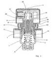
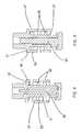
- FIG. 1is a view of a longitudinal section of a first embodiment of a precompression pump according to the invention, with the plunger rod completely extended.
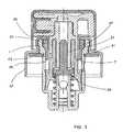
- FIG. 2is a view of a longitudinal section of the pump of FIG. 1 , with the plunger rod partially depressed and rotated 90°.
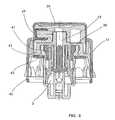
- FIG. 3is a view of a longitudinal section of the pump of FIG. 1 , with the plunger rod totally depressed.
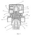
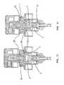
- FIGS. 4 , 5 , and 6are the equivalent of FIGS. 1 , 2 and 3 with respect to a second embodiment of the precompression pump according to the invention.
- FIG. 7is a view of a longitudinal section of a third embodiment of a precompression pump according to the invention, with the plunger rod totally extended.
- FIG. 8is a view of a longitudinal section of a plunger rod according to the invention.
- FIG. 9is a view of a longitudinal section of the plunger rod of FIG. 8 , rotated 90°.
- FIG. 10is a perspective view of the plunger rod of FIG. 8 .
- FIG. 11is a view of a longitudinal section of a fourth embodiment of a precompression pump according to the invention, with the plunger rod of FIG. 8 , totally extended.
- FIG. 12is a view of a longitudinal section of the pump of FIG. 11 , with the plunger rod totally depressed and rotated 90°.
- FIG. 13corresponds entirely with FIG. 11 , and is represented again in order to facilitate comparison with the pump of FIG. 14 , which has a retainer of increased longitude.
- FIGS. 1 to 3a first embodiment of a precompression pump according to the invention.
- the pumpincludes a cylinder 1 which defines a pump body. In the interior of the cylinder 1 is defined a pump chamber 3 .
- the cylinder 1has an inlet valve 5 arranged at the bottom of said cylinder 1 .
- the upper end of the cylinder 1is open.
- the inlet valve 5may be of any known type as for example a ball check valve as illustrated in the Figures.
- the inlet valve 5has a system for retaining the ball, to avoid said ball being unseated from its housing. Such retention systems are conventional and have not been illustrated in all of the Figures. An example of such may be observed in FIGS. 11 to 14 .
- the pump chamber 3remains closed, with respect to its upper part, by a piston 7 .
- Piston 7has a lower outwardly flaring lip seal 9 which is in sliding engagement with the interior of the cylinder 1 when the piston 7 reciprocates along the longitudinal axis 11 defined by the cylinder 1 .
- the piston 7has a upper outwardly flaring lip seal 13 , which is separated from the lower outwardly flaring lip seal 9 by a distance such that when the piston 7 is in its extended position there is a vent aperture 15 between both the outwardly flaring lip seals 9 and 13 .
- Piston 7has a central aperture 17 and an inwardly flaring lip seal 19 which rims the central aperture 17 .
- the pump plunger rod 21may travel along the longitudinal axis 11 lengthways in the central aperture 17 .
- the plunger rod 21is substantially a tube whose interior defines a communication passage 23 which is suitable for pump chamber 3 communication with the exterior, or more specifically with a cap 25 which includes a spray device 27 .
- the plunger rod 21defines in turn a longitudinal axis which is coincident with the longitudinal axis 11 defined by the cylinder 1 . At the lower end of the plunger rod 21 is found a plug 29 .
- This plug 29may be mounted in the plunger rod 21 by different means, as for example by friction, by snapping, or by a combination of the two.
- FIGS. 1 to 7are represented some plugs 29 secured uniquely by friction, whilst in the FIGS. 8 , 9 and 11 - 14 plugs 29 are represented which are secured by friction and which, at the same time, have a snap device.
- the part of the plug 29 which is housed inside the plunger rod 21is flattened, so as to not occupy all of the communication passage 23 , thus allowing discharge of the pumped fluid.
- the projecting part of plug 29has a shape approximately that of a cup with a diameter greater than the plunger rod 21 . In this way the inwardly flaring lip seal 19 of piston 7 can abut against the cup and thus avoid that the plunger rod 21 unseats totally from the piston 7 . Additionally the hermetic seal can thus be achieved between the piston 7 and the assembly formed by the plunger rod 21 and the plug 29 , the communication passage 23 being shut.
- a first helicoidal springdefines a first elastic member 31 which bears against, at one end, the bottom of the cylinder 1 whilst the other end bears against the cup of the plug 29 .
- This first helicoidal springbiases the assembly formed by the plunger rod 21 , the plug 29 and the piston 7 towards its extended position, in general outwards from the cylinder 1 .
- the upper end of the cylinder 1is open. Through said upper end may be introduced in the cylinder 1 the sundry common components which form the precompression pump: the inlet ball check valve 5 , the first helicoidal spring and the assembly formed by the plunger rod 21 , the plug 29 and the piston 7 .
- a retainer 33is then introduced which is retained in the upper end of the cylinder 1 , for example by means of a snapping mechanism.
- the retainer 33has a shoulder 35 on which bears the piston 7 , which is impelled outwards due to the force exerted by the first helicoidal spring. In this manner the unseating of the common components of the precompression pump is avoided and the assembly thus mounted can be handled and stored without problem.
- the retainer 33allows the manufacture of precompression pumps having different pump capacities, in which all the members are common except said retainer 33 .
- a precompression pump with a lesser pump capacitycan be obtained, since piston 7 , when in its upper extended position will define a lesser volume pump chamber 3 and correspondingly the quantity of pumped liquid will be less.
- a cap 25is mounted which has a spray device 27 . Both the cap 25 and the spray device 27 are independent of the present invention and may be of any design whatsoever.
- a securement device 37To secure the precompression pump to a container which contains the liquid to be pumped there is a securement device 37 .
- Sundry securement devices 37compatible with the present invention are possible.
- a metallic ferrulecould be used, having an upper retention cover 39 which bears on the upper end of the cylinder 1 , for example as represented in FIGS. 1-3 , 7 , and 11 - 14 .
- Another possible securement device 37is a device such as represented in FIGS. 4 to 6 , and which is described in documents ES P9900578 and ES P200000557, which have been included herein as reference.
- This securement device 37also has an upper retention cover 39 which bears on the upper end of the cylinder 1 .
- the securement devices 37also have a horizontal sealing surface 41 which is that which is applied on the upper edge of the container, possibly separated from said upper container edge by a watertight seal 43 .
- the second elastic member 47can be a conventional helicoidal spring, as represented in FIG. 7 .
- the upper bearing point 49 of the second elastic member 47is applied directly on the plunger rod 21 and is above the upper retention cover 39 . In this manner the height of the assembly is reduced.
- the second elastic member 47is of the same material as the plunger rod 21 and is joined to the plunger rod 21 in such manner that they form a single part.
- the assemblymay be obtained by plastics injection, such that only one physical part simultaneously performs the functions of plunger rod 21 and of the second elastic member 47 .
- An example of this second elastic member 47can be observed in FIGS. 1 to 6 and 11 to 14 , and in better detail in FIGS. 8 to 10 .
- the plunger rod 21has an annular projection 51 whose outer edge is prolonged by means of a cylindrical surface 53 parallel to the plunger rod 21 .
- the cylindrical surface 53forms a type of sleeve or sheath around the plunger rod body 21 .
- This cylindrical surface 53has slots 55 paired with respect to each other and separated from each other by two bond areas 57 .
- Each pair of slots 55 with the respective bond areas 57 thereofdefines a “level” of the cylindrical surface 53 .
- the lower end of the second elastic member 47bears directly on the piston 7 .
- the force of the second elastic member 47is transmitted directly to piston 7 , which in fact should be the subject of the elastic force.
- the operation of the precompression pumpis the following. Beginning in an inactive position, in which the plunger rod 21 is in its upper or extended position, and which corresponds to FIGS. 1 , 4 , 7 , 11 and 13 , the plunger rod 21 begins to travel downwards. The liquid in the interior of the pump chamber 3 is subjected to pressure and as such the pressure increases rapidly. If the plunger rod 21 continues its descent, the piston 7 is then already subject to an upward force, due to the liquid subjected to pressure, which overcomes the force of the second elastic member 47 , by which means the piston 7 (actually the inwardly flaring lip seal 19 ) ceases to bear against the cup (in its internal conical surface) of the plug 29 and allows the liquid to be discharged out to the communication passage 23 .
- the first elastic member 31pushes the entire assembly upwards.
- the second elastic member 47pushes the piston 7 towards the cup thus closing discharge to the communication passage 23 . This provokes negative pressure in the pump chamber 3 which forces open the inlet valve 5 .
Landscapes
- Engineering & Computer Science (AREA)
- General Engineering & Computer Science (AREA)
- Mechanical Engineering (AREA)
- Reciprocating Pumps (AREA)
- Details Of Reciprocating Pumps (AREA)
- Compressor (AREA)
- Closures For Containers (AREA)
Abstract
Description
- a cylinder which defines a pump body and in the interior of which there is a pump chamber,
- an inlet valve arranged at the bottom of the cylinder,
- a piston, the piston having a lower outwardly flaring lip seal, which lower outwardly flaring lip seal is suitable for sliding engagement with the interior of the cylinder, and an inwardly flaring lip seal which rims a central piston aperture,
- a plunger rod, suitable for sliding engagement with the central aperture, which plunger rod is hollow and has a communication passage in the interior thereof which is suitable for pump chamber communication with the exterior,
- an securement device suitable for securing the cylinder to a container, the securement device defining an upper retention cover,
- a first elastic member housed in the cylinder and a second elastic member.
Claims (15)
Priority Applications (2)
| Application Number | Priority Date | Filing Date | Title |
|---|---|---|---|
| US12/814,828US8016164B2 (en) | 2002-11-25 | 2010-06-14 | Low height precompression pump |
| US13/230,472US20120000943A1 (en) | 2002-11-25 | 2011-09-12 | Low height precompression pump |
Applications Claiming Priority (3)
| Application Number | Priority Date | Filing Date | Title |
|---|---|---|---|
| PCT/ES2002/000556WO2003053591A1 (en) | 2002-11-25 | 2002-11-25 | Reduced-height precompression pump |
| US10/536,496US7735693B2 (en) | 2002-11-25 | 2002-11-25 | Reduced-height precompression pump |
| US12/814,828US8016164B2 (en) | 2002-11-25 | 2010-06-14 | Low height precompression pump |
Related Parent Applications (3)
| Application Number | Title | Priority Date | Filing Date |
|---|---|---|---|
| US10/536,496ContinuationUS7735693B2 (en) | 2002-11-25 | 2002-11-25 | Reduced-height precompression pump |
| PCT/ES2002/000556ContinuationWO2003053591A1 (en) | 2002-11-25 | 2002-11-25 | Reduced-height precompression pump |
| US11/536,496ContinuationUS7561612B2 (en) | 2006-09-28 | 2006-09-28 | Laser source device, image display device equipped with the laser source device, and monitor device |
Related Child Applications (1)
| Application Number | Title | Priority Date | Filing Date |
|---|---|---|---|
| US13/230,472ContinuationUS20120000943A1 (en) | 2002-11-25 | 2011-09-12 | Low height precompression pump |
Publications (2)
| Publication Number | Publication Date |
|---|---|
| US20100252582A1 US20100252582A1 (en) | 2010-10-07 |
| US8016164B2true US8016164B2 (en) | 2011-09-13 |
Family
ID=8244420
Family Applications (3)
| Application Number | Title | Priority Date | Filing Date |
|---|---|---|---|
| US10/536,496Active2025-12-30US7735693B2 (en) | 2002-11-25 | 2002-11-25 | Reduced-height precompression pump |
| US12/814,828Expired - LifetimeUS8016164B2 (en) | 2002-11-25 | 2010-06-14 | Low height precompression pump |
| US13/230,472AbandonedUS20120000943A1 (en) | 2002-11-25 | 2011-09-12 | Low height precompression pump |
Family Applications Before (1)
| Application Number | Title | Priority Date | Filing Date |
|---|---|---|---|
| US10/536,496Active2025-12-30US7735693B2 (en) | 2002-11-25 | 2002-11-25 | Reduced-height precompression pump |
Family Applications After (1)
| Application Number | Title | Priority Date | Filing Date |
|---|---|---|---|
| US13/230,472AbandonedUS20120000943A1 (en) | 2002-11-25 | 2011-09-12 | Low height precompression pump |
Country Status (14)
| Country | Link |
|---|---|
| US (3) | US7735693B2 (en) |
| EP (1) | EP1565270B1 (en) |
| JP (1) | JP4309279B2 (en) |
| AR (1) | AR041901A1 (en) |
| AT (1) | ATE322344T1 (en) |
| AU (1) | AU2002354207A1 (en) |
| BR (1) | BR0215948B1 (en) |
| DE (1) | DE60210514T2 (en) |
| DK (1) | DK1565270T3 (en) |
| ES (1) | ES2258167T3 (en) |
| MX (1) | MXPA05005607A (en) |
| PT (1) | PT1565270E (en) |
| UA (1) | UA78626C2 (en) |
| WO (1) | WO2003053591A1 (en) |
Cited By (6)
| Publication number | Priority date | Publication date | Assignee | Title |
|---|---|---|---|---|
| US20120305604A1 (en)* | 2011-06-03 | 2012-12-06 | Ya-Tsan Wang | Nozzle assembly |
| US8439234B2 (en)* | 2009-12-21 | 2013-05-14 | Shanghai SR Packaging Technology Co., Ltd | Non-dripping suck-back nozzle |
| US20190151877A1 (en)* | 2016-08-04 | 2019-05-23 | Rpc Bramlage Gmbh | Finger spray pump and nozzle head for spray pump |
| USD980069S1 (en) | 2020-07-14 | 2023-03-07 | Ball Corporation | Metallic dispensing lid |
| US12168551B2 (en) | 2021-03-01 | 2024-12-17 | Ball Corporation | Metal container and end closure with seal |
| WO2025061899A1 (en) | 2023-09-19 | 2025-03-27 | Rieke Packaging Systems Limited | All plastic fine misting dispenser with pre-compression functionality |
Families Citing this family (24)
| Publication number | Priority date | Publication date | Assignee | Title |
|---|---|---|---|---|
| US7654419B2 (en) | 2004-09-17 | 2010-02-02 | Meadwestvaco Calmar, Inc. | Dispenser having elastomer discharge valve |
| FR2910449B1 (en)* | 2006-12-22 | 2009-03-06 | Rexam Dispensing Systems Sas | COMPACT PUMP HAVING CAPACITY FOR ROTULATING THE SPRAY WITH RESPECT TO THE PISTON. |
| DE102008036976A1 (en)* | 2008-08-08 | 2010-02-11 | Behr Gmbh & Co. Kg | Pumping device and method for operating a pumping device |
| JP5413895B2 (en)* | 2008-10-31 | 2014-02-12 | 株式会社吉野工業所 | Pump pressing head and pressing head type discharge pump |
| IT1393854B1 (en)* | 2009-04-01 | 2012-05-11 | Emsar Spa | DISPENSER. |
| US8337175B2 (en) | 2009-12-22 | 2012-12-25 | Smith & Nephew, Inc. | Disposable pumping system and coupler |
| FR2956649B1 (en)* | 2010-02-24 | 2012-08-03 | Valois Sas | FLUID PRODUCT DISPENSING DEVICE AND FLUID PRODUCT DISPENSING DEVICE COMPRISING SUCH ORGAN. |
| WO2011116201A2 (en) | 2010-03-18 | 2011-09-22 | Meadwestvaco Calmar, Inc. | Pump and bottle fitments and methods for using the same |
| FR2961496B1 (en)* | 2010-06-16 | 2013-02-15 | Rexam Dispensing Sys | SYSTEM FOR DISPENSING A FLUID PRODUCT |
| US9016527B2 (en)* | 2010-10-20 | 2015-04-28 | Meadwestvaco Calmar, Inc. | Precompression pump mechanisms |
| FR2998198B1 (en)* | 2012-11-22 | 2015-05-29 | Aptar France Sas | FLUID PRODUCT DISPENSING MEMBER. |
| GB201221063D0 (en) | 2012-11-23 | 2013-01-09 | 3M Innovative Properties Co | Metered dose dispensing valve |
| JP6137604B2 (en)* | 2013-03-11 | 2017-05-31 | 株式会社三谷バルブ | Pump mechanism for discharging contents of container body and pump-type product equipped with this pump mechanism |
| DE102013113791A1 (en)* | 2013-12-10 | 2015-06-11 | Rpc Bramlage Gmbh | donor |
| JP5972332B2 (en)* | 2014-09-26 | 2016-08-17 | 本田技研工業株式会社 | Approach notification device for saddle riding type vehicles |
| WO2016062716A2 (en)* | 2014-10-20 | 2016-04-28 | Rieke Packaging Systems Limited | Pump dispensers |
| US11148400B2 (en) | 2016-04-06 | 2021-10-19 | Tekni-Plex, Inc. | Thermally laminated tab liner |
| US11787153B2 (en) | 2016-04-06 | 2023-10-17 | Tekni-Plex, Inc. | Thermally laminated tab liner |
| FR3090417B1 (en)* | 2018-12-19 | 2020-12-18 | Aptar France Sas | Fluid dispenser device |
| DE102019132345A1 (en)* | 2019-01-29 | 2020-07-30 | Rpc Bramlage Gmbh | Plastic spring |
| DE102019132343A1 (en) | 2019-01-29 | 2020-07-30 | Rpc Bramlage Gmbh | Dispenser for dispensing flowable, for example liquid or pasty masses |
| CN115335035A (en) | 2020-01-27 | 2022-11-11 | 格尼菲斯公司 | Biological filler for restoring and regenerating tissue |
| CN111874436A (en)* | 2020-08-18 | 2020-11-03 | 广州尚功塑胶有限公司 | An all-plastic pump |
| CN112389849B (en)* | 2020-10-23 | 2024-11-26 | 广州尚功塑胶有限公司 | A double-spring all-plastic vacuum pump |
Citations (16)
| Publication number | Priority date | Publication date | Assignee | Title |
|---|---|---|---|---|
| US4228931A (en)* | 1978-02-09 | 1980-10-21 | Adm S.P.A. | Manually operated pump for dispensing micronized liquids at a predetermined pressure |
| US4278189A (en) | 1979-12-17 | 1981-07-14 | Ethyl Products Company | Accumulative pressure pump |
| US4607765A (en)* | 1984-04-19 | 1986-08-26 | S.A.R. S.P.A. | Manually operated pump for the delivery under pressure of liquid substances |
| US5147073A (en)* | 1991-02-11 | 1992-09-15 | Spruhventile Gmbh | Fluid pump dispenser for pharmaceutical use |
| US5192006A (en) | 1991-05-01 | 1993-03-09 | Risdon Corporation | Low profile pump |
| US5375745A (en) | 1991-09-05 | 1994-12-27 | Ing. Erich Pfeiffer Gmbh & Co. Kg | Media dispenser with initial pressure-relief state |
| US5850948A (en) | 1996-09-13 | 1998-12-22 | Valois S.A. | Finger-operable pump with piston biasing post |
| US6036059A (en) | 1998-06-16 | 2000-03-14 | Risdon/Ams Usa, Inc. | Low profile and low force actuation dispensing pump |
| US6196424B1 (en)* | 1997-05-29 | 2001-03-06 | Rexam Sofab | Articulated piston pump |
| US6220483B1 (en) | 1997-02-05 | 2001-04-24 | Airspray International B.V. | Dispensing assembly for dispensing two liquid components |
| US6286726B1 (en) | 1999-03-03 | 2001-09-11 | Microspray Delta S.P.A. | Manually operated pump for dispensing liquids under pressure |
| US20010022309A1 (en) | 2000-03-20 | 2001-09-20 | Firmin Garcia | Dispensing member having an outlet valve formed by a differential piston |
| US20010052529A1 (en)* | 2000-03-20 | 2001-12-20 | Firmin Garcia | Fluid-dispensing member having an off-center delivery channel |
| US6332561B1 (en) | 1998-03-26 | 2001-12-25 | Valois S.A. | Airless dispensing device |
| JP2002273278A (en) | 2001-03-21 | 2002-09-24 | Yoshino Kogyosho Co Ltd | Accumulation type liquid ejector made of synthetic resin |
| JP2002273279A (en) | 2001-03-22 | 2002-09-24 | Yoshino Kogyosho Co Ltd | Pressure accumulation type liquid spray unit |
Family Cites Families (16)
| Publication number | Priority date | Publication date | Assignee | Title |
|---|---|---|---|---|
| US3414169A (en)* | 1967-02-17 | 1968-12-03 | Diamond Int Corp | Liquid dispenser |
| FR2149671A6 (en)* | 1971-08-19 | 1973-03-30 | Step | |
| US4274560A (en)* | 1976-04-30 | 1981-06-23 | Emson Research Incorporated | Atomizing pump dispenser |
| US4230242A (en)* | 1979-03-26 | 1980-10-28 | Philip Meshberg | Triple seal valve member for an atomizing pump dispenser |
| US5108013A (en)* | 1984-04-16 | 1992-04-28 | Risdon Corporation | Pump for dispensing liquid from a container |
| US4986453A (en)* | 1989-05-15 | 1991-01-22 | The Pittway Corporation | Atomizing pump |
| DE68909310T2 (en)* | 1988-06-02 | 1994-03-24 | Tech De Pulverisation Step Par | Admission pressure metering pump with improved suction behavior. |
| US4895279A (en)* | 1988-07-25 | 1990-01-23 | Emson Research Inc. | Flat-top valve member for an atomizing pump dispenser |
| US5020696A (en)* | 1989-11-27 | 1991-06-04 | Rjs Industries, Inc. | Atomizing fluid dispenser two |
| US4984702A (en)* | 1990-03-30 | 1991-01-15 | Specialty Packaging Licensing Company, Inc. | Assembly for securing and sealing a dispenser to a flanged container |
| US5038965A (en)* | 1990-04-06 | 1991-08-13 | Spruhventile Gmbh | Pump dispenser for delivering a predetermined dosage regardless of method of actuation |
| FR2668958B1 (en)* | 1990-11-13 | 1994-05-20 | Valois | DEVICE FOR SPRAYING OR DISPENSING FLUID PRODUCT, WITH SUCTION OF THE PRODUCT CONTAINED IN THE OUTPUT CHANNEL AT THE END OF OPERATION. |
| US5163588A (en)* | 1991-04-10 | 1992-11-17 | Bespak Plc | Atomizing pump dispenser for water based formulations |
| US5664706A (en)* | 1994-10-13 | 1997-09-09 | Bespak Plc | Apparatus for dispensing liquid in aerosol spray form |
| SI9600118A (en)* | 1995-04-13 | 1996-10-31 | Monturas Sa | Precompression pump sprayer |
| US6209759B1 (en)* | 1997-07-04 | 2001-04-03 | Valois S.A. | Hand-operated pump with a free floating sleeve piston |
- 2002
- 2002-11-25JPJP2003554344Apatent/JP4309279B2/ennot_activeExpired - Fee Related
- 2002-11-25DEDE60210514Tpatent/DE60210514T2/ennot_activeExpired - Lifetime
- 2002-11-25EPEP02787985Apatent/EP1565270B1/ennot_activeExpired - Lifetime
- 2002-11-25WOPCT/ES2002/000556patent/WO2003053591A1/enactiveIP Right Grant
- 2002-11-25AUAU2002354207Apatent/AU2002354207A1/ennot_activeAbandoned
- 2002-11-25PTPT02787985Tpatent/PT1565270E/enunknown
- 2002-11-25DKDK02787985Tpatent/DK1565270T3/enactive
- 2002-11-25MXMXPA05005607Apatent/MXPA05005607A/enactiveIP Right Grant
- 2002-11-25UAUAA200506260Apatent/UA78626C2/enunknown
- 2002-11-25ESES02787985Tpatent/ES2258167T3/ennot_activeExpired - Lifetime
- 2002-11-25BRBRPI0215948-1Apatent/BR0215948B1/enactiveIP Right Grant
- 2002-11-25ATAT02787985Tpatent/ATE322344T1/enactive
- 2002-11-25USUS10/536,496patent/US7735693B2/enactiveActive
- 2003
- 2003-11-05ARARP030104060Apatent/AR041901A1/enactiveIP Right Grant
- 2010
- 2010-06-14USUS12/814,828patent/US8016164B2/ennot_activeExpired - Lifetime
- 2011
- 2011-09-12USUS13/230,472patent/US20120000943A1/ennot_activeAbandoned
Patent Citations (16)
| Publication number | Priority date | Publication date | Assignee | Title |
|---|---|---|---|---|
| US4228931A (en)* | 1978-02-09 | 1980-10-21 | Adm S.P.A. | Manually operated pump for dispensing micronized liquids at a predetermined pressure |
| US4278189A (en) | 1979-12-17 | 1981-07-14 | Ethyl Products Company | Accumulative pressure pump |
| US4607765A (en)* | 1984-04-19 | 1986-08-26 | S.A.R. S.P.A. | Manually operated pump for the delivery under pressure of liquid substances |
| US5147073A (en)* | 1991-02-11 | 1992-09-15 | Spruhventile Gmbh | Fluid pump dispenser for pharmaceutical use |
| US5192006A (en) | 1991-05-01 | 1993-03-09 | Risdon Corporation | Low profile pump |
| US5375745A (en) | 1991-09-05 | 1994-12-27 | Ing. Erich Pfeiffer Gmbh & Co. Kg | Media dispenser with initial pressure-relief state |
| US5850948A (en) | 1996-09-13 | 1998-12-22 | Valois S.A. | Finger-operable pump with piston biasing post |
| US6220483B1 (en) | 1997-02-05 | 2001-04-24 | Airspray International B.V. | Dispensing assembly for dispensing two liquid components |
| US6196424B1 (en)* | 1997-05-29 | 2001-03-06 | Rexam Sofab | Articulated piston pump |
| US6332561B1 (en) | 1998-03-26 | 2001-12-25 | Valois S.A. | Airless dispensing device |
| US6036059A (en) | 1998-06-16 | 2000-03-14 | Risdon/Ams Usa, Inc. | Low profile and low force actuation dispensing pump |
| US6286726B1 (en) | 1999-03-03 | 2001-09-11 | Microspray Delta S.P.A. | Manually operated pump for dispensing liquids under pressure |
| US20010022309A1 (en) | 2000-03-20 | 2001-09-20 | Firmin Garcia | Dispensing member having an outlet valve formed by a differential piston |
| US20010052529A1 (en)* | 2000-03-20 | 2001-12-20 | Firmin Garcia | Fluid-dispensing member having an off-center delivery channel |
| JP2002273278A (en) | 2001-03-21 | 2002-09-24 | Yoshino Kogyosho Co Ltd | Accumulation type liquid ejector made of synthetic resin |
| JP2002273279A (en) | 2001-03-22 | 2002-09-24 | Yoshino Kogyosho Co Ltd | Pressure accumulation type liquid spray unit |
Non-Patent Citations (2)
| Title |
|---|
| European Search Report EP1565270A1, published Aug. 24, 2005. |
| International Search Report for corresponding PCT/ES02/00556, publication WO2004/053591, mailed Mar. 24, 2003. |
Cited By (7)
| Publication number | Priority date | Publication date | Assignee | Title |
|---|---|---|---|---|
| US8439234B2 (en)* | 2009-12-21 | 2013-05-14 | Shanghai SR Packaging Technology Co., Ltd | Non-dripping suck-back nozzle |
| US20120305604A1 (en)* | 2011-06-03 | 2012-12-06 | Ya-Tsan Wang | Nozzle assembly |
| US20190151877A1 (en)* | 2016-08-04 | 2019-05-23 | Rpc Bramlage Gmbh | Finger spray pump and nozzle head for spray pump |
| US10512926B2 (en)* | 2016-08-04 | 2019-12-24 | Rpc Bramlage Gmbh | Finger spray pump and nozzle head for spray pump |
| USD980069S1 (en) | 2020-07-14 | 2023-03-07 | Ball Corporation | Metallic dispensing lid |
| US12168551B2 (en) | 2021-03-01 | 2024-12-17 | Ball Corporation | Metal container and end closure with seal |
| WO2025061899A1 (en) | 2023-09-19 | 2025-03-27 | Rieke Packaging Systems Limited | All plastic fine misting dispenser with pre-compression functionality |
Also Published As
| Publication number | Publication date |
|---|---|
| AU2002354207A1 (en) | 2003-07-09 |
| US20100252582A1 (en) | 2010-10-07 |
| US20060151541A1 (en) | 2006-07-13 |
| DK1565270T3 (en) | 2006-08-14 |
| ATE322344T1 (en) | 2006-04-15 |
| PT1565270E (en) | 2006-07-31 |
| US20120000943A1 (en) | 2012-01-05 |
| EP1565270A1 (en) | 2005-08-24 |
| WO2003053591A1 (en) | 2003-07-03 |
| US7735693B2 (en) | 2010-06-15 |
| BR0215948A (en) | 2005-08-09 |
| MXPA05005607A (en) | 2005-07-27 |
| DE60210514T2 (en) | 2006-09-21 |
| UA78626C2 (en) | 2007-04-10 |
| BR0215948B1 (en) | 2011-04-05 |
| JP2006507437A (en) | 2006-03-02 |
| DE60210514D1 (en) | 2006-05-18 |
| ES2258167T3 (en) | 2006-08-16 |
| AR041901A1 (en) | 2005-06-01 |
| JP4309279B2 (en) | 2009-08-05 |
| EP1565270B1 (en) | 2006-04-05 |
Similar Documents
| Publication | Publication Date | Title |
|---|---|---|
| US8016164B2 (en) | Low height precompression pump | |
| US4051983A (en) | Pump sprayer | |
| EP0755305B1 (en) | Manually operated reciprocating liquid pump | |
| US4511065A (en) | Manually actuated pump having pliant piston | |
| DE69203536T2 (en) | Pump dispenser for liquids. | |
| JP3136107B2 (en) | Precompression pump / spray | |
| US5353969A (en) | Invertible pump sprayer having spiral vent path | |
| US7837070B2 (en) | Simplified pump for dispensing fluid substances withdrawn from a container | |
| CN1136526A (en) | Precompression pump sprayer | |
| US11618045B2 (en) | Device for dispensing a fluid product | |
| US20060231577A1 (en) | Viscous liquid dispensing pump | |
| IL114679A (en) | Dispensing pump | |
| AU682918B2 (en) | Pump sprayer with stationary discharge | |
| WO2014181218A2 (en) | Device for dispensing fluids | |
| US6126038A (en) | Atomizing pump spray | |
| US6681961B2 (en) | Pump having a decompression device | |
| JP5090517B2 (en) | Extrusion container | |
| JP2018015685A (en) | Spring pressure accumulation type spray pump | |
| EP0689876A1 (en) | Pump sprayer with stationary discharge | |
| US20030155377A1 (en) | Finger-operated spray pump ejaculating fluid in fixed quantity | |
| US7243819B2 (en) | Simplified invertible pump for dispensing atomized liquids | |
| KR102062002B1 (en) | Pump vessel | |
| CN119137047A (en) | Pumps and spray containers | |
| KR20240013631A (en) | Content exhaust pump |
Legal Events
| Date | Code | Title | Description |
|---|---|---|---|
| AS | Assignment | Owner name:SAINT-GOBAIN CALMAR S.A., SPAIN Free format text:ASSIGNMENT OF ASSIGNORS INTEREST;ASSIGNORS:PARES MONTANER, PERE;RIBERA TURRO, VICTOR;MARTORELL PENA, HAYDEE;REEL/FRAME:026004/0557 Effective date:20050708 Owner name:MEADWESTVACO CALMAR, S.A., SPAIN Free format text:CHANGE OF NAME;ASSIGNOR:SAINT-GOBAIN CALMAR, S.A.;REEL/FRAME:026677/0898 Effective date:20060912 | |
| STCF | Information on status: patent grant | Free format text:PATENTED CASE | |
| AS | Assignment | Owner name:MWV INTERNATIONAL S.A.R.L., SWITZERLAND Free format text:ASSIGNMENT OF ASSIGNORS INTEREST;ASSIGNOR:MEADWESTVACO CALMAR, S.L.;REEL/FRAME:033878/0911 Effective date:20131220 Owner name:MEADWESTVACO CALMAR, S.L., SPAIN Free format text:CHANGE OF NAME;ASSIGNOR:MEADWESTVACO CALMAR, S.A.;REEL/FRAME:033889/0024 Effective date:20130628 | |
| FPAY | Fee payment | Year of fee payment:4 | |
| AS | Assignment | Owner name:WESTROCK DISPENSING SYSTEMS BARCELONA, S.L., SPAIN Free format text:ASSIGNMENT OF ASSIGNORS INTEREST;ASSIGNOR:MWV INTERNATIONAL S.A.R.L.;REEL/FRAME:041164/0893 Effective date:20170127 | |
| MAFP | Maintenance fee payment | Free format text:PAYMENT OF MAINTENANCE FEE, 8TH YEAR, LARGE ENTITY (ORIGINAL EVENT CODE: M1552); ENTITY STATUS OF PATENT OWNER: LARGE ENTITY Year of fee payment:8 | |
| MAFP | Maintenance fee payment | Free format text:PAYMENT OF MAINTENANCE FEE, 12TH YEAR, LARGE ENTITY (ORIGINAL EVENT CODE: M1553); ENTITY STATUS OF PATENT OWNER: LARGE ENTITY Year of fee payment:12 |