US8016131B2 - Display tray - Google Patents
Display trayDownload PDFInfo
- Publication number
- US8016131B2 US8016131B2US11/367,741US36774106AUS8016131B2US 8016131 B2US8016131 B2US 8016131B2US 36774106 AUS36774106 AUS 36774106AUS 8016131 B2US8016131 B2US 8016131B2
- Authority
- US
- United States
- Prior art keywords
- shelf
- tray
- floor
- support means
- display
- Prior art date
- Legal status (The legal status is an assumption and is not a legal conclusion. Google has not performed a legal analysis and makes no representation as to the accuracy of the status listed.)
- Expired - Fee Related, expires
Links
Images


Classifications
- A—HUMAN NECESSITIES
- A47—FURNITURE; DOMESTIC ARTICLES OR APPLIANCES; COFFEE MILLS; SPICE MILLS; SUCTION CLEANERS IN GENERAL
- A47F—SPECIAL FURNITURE, FITTINGS, OR ACCESSORIES FOR SHOPS, STOREHOUSES, BARS, RESTAURANTS OR THE LIKE; PAYING COUNTERS
- A47F5/00—Show stands, hangers, or shelves characterised by their constructional features
- A47F5/0018—Display racks with shelves or receptables
- A—HUMAN NECESSITIES
- A47—FURNITURE; DOMESTIC ARTICLES OR APPLIANCES; COFFEE MILLS; SPICE MILLS; SUCTION CLEANERS IN GENERAL
- A47F—SPECIAL FURNITURE, FITTINGS, OR ACCESSORIES FOR SHOPS, STOREHOUSES, BARS, RESTAURANTS OR THE LIKE; PAYING COUNTERS
- A47F5/00—Show stands, hangers, or shelves characterised by their constructional features
- A47F5/0043—Show shelves
- A47F5/0068—Shelf extensions, e.g. fixed on price rail
- A—HUMAN NECESSITIES
- A47—FURNITURE; DOMESTIC ARTICLES OR APPLIANCES; COFFEE MILLS; SPICE MILLS; SUCTION CLEANERS IN GENERAL
- A47B—TABLES; DESKS; OFFICE FURNITURE; CABINETS; DRAWERS; GENERAL DETAILS OF FURNITURE
- A47B2220/00—General furniture construction, e.g. fittings
- A47B2220/0036—Brackets
- A47B2220/0038—Brackets having a pincer shape supporting a cantilever shelf
Definitions
- This inventionrelates to methods and apparatus for holding and displaying merchandise or the like. More particularly, it relates to display shelves or trays adapted for mounting on the outer edges of conventional merchandise display shelves to support and display products within view and easy access for potential users.
- Retail businessessuch as grocery stores, convenience stores, etc., commonly arrange merchandise for sale on display shelves which support and display goods for sale at convenient locations so that the goods are attractive and easily accessible to potential customers.
- apparatus for supporting and displaying merchandisecomprises a plurality of horizontal parallel shelves supported in fixed relation to each other.
- Each shelfcomprises a flat, thin sheet of rigid material such as steel or the like.
- each shelfincludes a flange depending downwardly from the outer edge thereof to rigidly reinforce the shelf. This flange is often used as a support for graphic information, such as price, etc., relative to the goods displayed on the shelf.
- Most such shelvesalso have one or more rows of holes passing therethrough aligned parallel with and spaced from the outer or front edge of the shelf. These holes are generally used to support spacers or edge walls to contain or divide goods placed on the shelf.
- conventional display shelvesare usually pre-assembled large fixtures, they afford little opportunity for convenient modification or rearrangement to accommodate unique display arrangements.
- display traysadapted to be mounted on and extend from the outer (front) edges of conventional shelves are provided which can be easily and readily added, removed and rearranged as desired.
- the display trays of the inventionmay be inexpensively and conveniently formed in various sizes and shapes to perform various specialized functions. Moreover, the display trays may be added, removed or rearranged quickly and conveniently without the use of any tools.
- the unique trays of the inventionthus provide a highly desireable flexibility in display apparatus which is inexpensive and conveniently used.
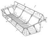
- FIG. 1is a top front perspective view of a preferred embodiment of the display tray of the invention
- FIG. 2is an elevational view of the left-hand end of the display tray of FIG. 1 ;
- FIG. 3is an elevational view of the left-hand end of the display tray of FIG. 1 mounted on a display shelf shown in cross-section;
- FIG. 4is a perspective view of the front edge portion of a display shelf and the tray of FIG. 1 illustrating the method of mounting the tray on the shelf;
- FIG. 5is a top front perspective view of the display tray of FIG. 1 mounted on a display shelf.
- the term “shelf”is used herein to mean any substantially flat structure having a floor on which products or packages containing products may be placed or suspended from for display.
- the term “tray”is used to describe a structure which has a floor on which goods may be placed (or from which goods may be suspended) for display.
- Such floorsmay be formed of any suitable materials and may be continuous structure or may be formed of perforated or slotted members.
- Such traysmay have walls extending upwardly or downwardly to form cavities in which goods may be supported and displayed. Accordingly, the tray may define one or more cavities above the floor or the floor may support one or more cavities which depend downwardly from the floor.
- the floormay have slots, hooks or the like from which goods may be suspended. Accordingly, the term “tray” is used broadly to describe any structure on, in or from which goods may be placed or suspended for display.
- the portion of the tray unit which is closest the shelf on which it is supportedis described as the back or rear and the portion most remote from the supporting shelf is described as the front.
- spatial orientation and relative termssuch as “upwardly,” “downwardly,” “rearwardly,” “horizontally,” “above,” “below,” “upper,” “lower” and the like are used in reference to the position of the tray when the tray is mounted on a supporting shelf for use.
- the embodiment illustratedcomprises a display tray 10 having a back wall 11 , a front wall 12 , end walls 13 and a floor 14 .
- the display tray 10is supported by a mounting panel or support means 15 which comprises a first member 16 attached to and extending from the back wall 11 and a plurality of connection posts 20 .
- the first member 16has a bottom face 19 which lies in a substantially horizontal plane substantially normal to the back wall 11 (parallel with the plane of the floor 14 ).
- a plurality of second members, preferably in the form of studs or posts 20depend from and extend rearwardly from first member 16 (away from back wall 11 ).
- Each post 20depends from and extends substantially parallel with (but horizontally displaced from) bottom face 19 of first member 16 .
- the top surface 22 of each post 20lies in a horizontal plane spaced from the horizontal plane of bottom face 19 a distance substantially equal to the vertical thickness of the display shelf on which it is to be mounted.
- conventional display shelves 30usually include one or more rows of holes 31 . At least one row extends parallel with and is spaced from the front edge 21 .
- the holes 31are ordinarily 1 ⁇ 4 inch diameter holes on one inch centers.
- the first row of holesis approximately one inch from the front edge of the shelf and the thickness of the shelf 30 is usually about 1 ⁇ 8 to about 1/16 inch. Although these dimensions may vary from one shelf manufacturer to another, the sizing, arrangement and spacing of posts 20 may readily be varied to accommodate variations among standard dimensions of manufactured shelving.
- posts 20should be sized to fit in holes 31 and the vertical spacing between top surface 22 of each post 20 and the bottom face 19 of first member 16 should be appropriately sized so that the posts 20 may be inserted into holes 31 and the top surfaces 22 of posts 20 rest against the bottom surface of display shelf 30 and support the tray 10 adjacent the front edge 21 of tray 10 as illustrated in FIG. 5 .
- a tray 10 with support structure 15 as described abovemay be easily attached to the front edge of shelf 30 by simply rotating and positioning the tray 10 so that the ends of posts 20 are vertically aligned with holes 31 (see FIG. 4 ); inserting the posts 20 through the holes 31 ; and then rotating the tray 10 90° so that posts 20 extend along and rest in contact with the bottom surface of shelf 30 .
- the bottom face 19 of first member 16rests on the top surface of shelf 30 and the top surfaces 22 of posts 20 rest on the bottom surface of shelf 30 .
- the tray 10is thus firmly suspended from the front edge of the shelf 30 as shown in FIG. 3 .
- tray 10may be provided with an upstanding flange or lip 24 which provides an alternate surface for displaying such information.
- the lip 24may be any desired shape or size and is preferably positioned immediately above the front edge 21 as illustrated in FIG. 3 . Lip 24 may also be shaped and positioned for use as a front wall which retains goods displayed on shelf 30 .
- a tab 25may be formed on or attached to the front wall 12 or any other convenient location on the tray 10 .
- tab 25depends downwardly and outwardly from the top edge of front wall 12 .
- the tab 25may be formed as an integral portion of front wall 12 or positioned at any appropriate location.
- the tray of the inventionmay take various forms.
- the embodiment illustratedcomprises a distinct back wall 11 , front wall 12 , end walls 13 and floor 14 to define a tray cavity.
- the floor 14includes a plurality of parallel slots 17 .
- the tray of the inventionneed not include front or back walls and need not include end walls.
- the traymay, for example, be in the form of a floor with one or more depressions or cavities therein.
- the trayneed not be formed of solid walls or floors. These structures may be, for example, slotted (as shown in floor 14 ), perforated or similar structures.
- the floormay be formed as or include hooks or other structure from which goods may be suspended. Accordingly, in its simplest form the tray may comprise a floor and support means such as the support means 15 illustrated and described.
- the tray and support structure of the inventionmay readily be fabricated from any of various suitable materials.
- the structuresare formed of molded plastics, acrylics or the like to form unitary transparent, translucent or tinted bodies.
- various other materials and manufacturing technologiesmay be used as desired.
- the trayneed not be in the form of a rectangular basket structure as illustrated. It is only necessary that the tray of the invention include a floor which is supportable on a substantially horizontal shelf by support means which maintains the floor in a fixed position substantially parallel with and forming an extension of the shelf on which it is supported.
Landscapes
- Display Racks (AREA)
Abstract
Description
Claims (8)
Priority Applications (1)
| Application Number | Priority Date | Filing Date | Title |
|---|---|---|---|
| US11/367,741US8016131B2 (en) | 2006-03-06 | 2006-03-06 | Display tray |
Applications Claiming Priority (1)
| Application Number | Priority Date | Filing Date | Title |
|---|---|---|---|
| US11/367,741US8016131B2 (en) | 2006-03-06 | 2006-03-06 | Display tray |
Publications (2)
| Publication Number | Publication Date |
|---|---|
| US20070205167A1 US20070205167A1 (en) | 2007-09-06 |
| US8016131B2true US8016131B2 (en) | 2011-09-13 |
Family
ID=38470588
Family Applications (1)
| Application Number | Title | Priority Date | Filing Date |
|---|---|---|---|
| US11/367,741Expired - Fee RelatedUS8016131B2 (en) | 2006-03-06 | 2006-03-06 | Display tray |
Country Status (1)
| Country | Link |
|---|---|
| US (1) | US8016131B2 (en) |
Cited By (5)
| Publication number | Priority date | Publication date | Assignee | Title |
|---|---|---|---|---|
| US20120146480A1 (en)* | 2010-12-08 | 2012-06-14 | Ssw Holding Company, Inc. | Multi-material basket for refrigerator or freezer |
| US20150136719A1 (en)* | 2013-11-18 | 2015-05-21 | Nexxspan Healthcare, Llc | Storage bin system |
| US20150260446A1 (en)* | 2014-03-13 | 2015-09-17 | Mark W. Levie | Removable shelf liner |
| US9215939B2 (en) | 2013-10-14 | 2015-12-22 | Target Brands, Inc. | Retail fixtures |
| USD774800S1 (en)* | 2014-10-03 | 2016-12-27 | ATA Retail Services, Inc. | Merchandise display tray |
Families Citing this family (12)
| Publication number | Priority date | Publication date | Assignee | Title |
|---|---|---|---|---|
| US20060283819A1 (en)* | 2005-06-17 | 2006-12-21 | B-O-F Corporation | Modular Shelf Management System |
| USD616224S1 (en)* | 2009-11-16 | 2010-05-25 | International Paper Company | Display tray |
| USD640890S1 (en)* | 2010-10-26 | 2011-07-05 | Displays By Martin Paul, Inc. - Creative Center | Display shelf |
| JP5798362B2 (en)* | 2011-04-21 | 2015-10-21 | 株式会社岡村製作所 | Article placement fixtures |
| USD732324S1 (en)* | 2013-08-06 | 2015-06-23 | Target Brands, Inc. | Bin |
| USD805320S1 (en)* | 2017-01-19 | 2017-12-19 | Helen Of Troy Limited | Suction basket |
| US9962016B1 (en)* | 2017-01-25 | 2018-05-08 | Target Brands, Inc. | Retail display bracket |
| US10306997B2 (en)* | 2017-10-19 | 2019-06-04 | Array Canada, Inc. | Product display apparatus |
| USD878095S1 (en)* | 2018-03-01 | 2020-03-17 | Coulter Ventures, Llc. | Storage tray |
| US10939670B2 (en)* | 2019-01-29 | 2021-03-09 | Key Partners Group, Inc. | Beehive frame stabilization device |
| USD942773S1 (en)* | 2020-03-19 | 2022-02-08 | Xiamen Lota International Co., Ltd. | Shower shelf |
| USD996825S1 (en)* | 2023-05-10 | 2023-08-29 | Junbo Zheng | Stackable bin |
Citations (6)
| Publication number | Priority date | Publication date | Assignee | Title |
|---|---|---|---|---|
| US3647078A (en)* | 1970-07-27 | 1972-03-07 | Henschel Steinau Co | Shelf extender |
| US4828121A (en)* | 1987-12-14 | 1989-05-09 | Willcocks Jr Reginald | Shelf expander for supermarkets |
| US5549054A (en)* | 1994-01-12 | 1996-08-27 | Fast Industries, Inc. | Shelf extender |
| US20020139808A1 (en)* | 2001-03-30 | 2002-10-03 | Grueneberg Bevan E. | Shelf extender display unit |
| US6907829B2 (en)* | 2003-04-03 | 2005-06-21 | Mii, Inc. | Shelf extension |
| USD551953S1 (en)* | 2005-11-21 | 2007-10-02 | Smalley Daniel J | Shelf extender |
- 2006
- 2006-03-06USUS11/367,741patent/US8016131B2/ennot_activeExpired - Fee Related
Patent Citations (6)
| Publication number | Priority date | Publication date | Assignee | Title |
|---|---|---|---|---|
| US3647078A (en)* | 1970-07-27 | 1972-03-07 | Henschel Steinau Co | Shelf extender |
| US4828121A (en)* | 1987-12-14 | 1989-05-09 | Willcocks Jr Reginald | Shelf expander for supermarkets |
| US5549054A (en)* | 1994-01-12 | 1996-08-27 | Fast Industries, Inc. | Shelf extender |
| US20020139808A1 (en)* | 2001-03-30 | 2002-10-03 | Grueneberg Bevan E. | Shelf extender display unit |
| US6907829B2 (en)* | 2003-04-03 | 2005-06-21 | Mii, Inc. | Shelf extension |
| USD551953S1 (en)* | 2005-11-21 | 2007-10-02 | Smalley Daniel J | Shelf extender |
Cited By (9)
| Publication number | Priority date | Publication date | Assignee | Title |
|---|---|---|---|---|
| US20120146480A1 (en)* | 2010-12-08 | 2012-06-14 | Ssw Holding Company, Inc. | Multi-material basket for refrigerator or freezer |
| US9417007B2 (en)* | 2010-12-08 | 2016-08-16 | Ssw Holding Company, Inc. | Multi-material basket for refrigerator or freezer |
| US10281198B2 (en) | 2010-12-08 | 2019-05-07 | Ssw Holding Company, Llc | Multi-material basket for refrigerator or freezer |
| US11262122B2 (en) | 2010-12-08 | 2022-03-01 | Ssw Advanced Technologies, Llc | Multi-lateral basket for refrigerator or freezer |
| US9215939B2 (en) | 2013-10-14 | 2015-12-22 | Target Brands, Inc. | Retail fixtures |
| US20150136719A1 (en)* | 2013-11-18 | 2015-05-21 | Nexxspan Healthcare, Llc | Storage bin system |
| US9386865B2 (en)* | 2013-11-18 | 2016-07-12 | Nexxspan Healthcare, Llc | Storage bin system |
| US20150260446A1 (en)* | 2014-03-13 | 2015-09-17 | Mark W. Levie | Removable shelf liner |
| USD774800S1 (en)* | 2014-10-03 | 2016-12-27 | ATA Retail Services, Inc. | Merchandise display tray |
Also Published As
| Publication number | Publication date |
|---|---|
| US20070205167A1 (en) | 2007-09-06 |
Similar Documents
| Publication | Publication Date | Title |
|---|---|---|
| US8016131B2 (en) | Display tray | |
| US4262439A (en) | Display stand | |
| US5509541A (en) | Bracket construction | |
| US5505314A (en) | Display rack | |
| US6564952B1 (en) | Merchandising display | |
| US5351841A (en) | Merchandise case with advertising display | |
| US20080156749A1 (en) | Free-standing, point-of-purchase display | |
| US6769656B1 (en) | Assembly for supporting and displaying objects | |
| US5836459A (en) | Compact, High visibility display rack and configuration | |
| US20170099961A1 (en) | Shelving assembly | |
| US4938368A (en) | Merchandise display and dispenser rack | |
| US8827089B2 (en) | Vertical display structure with bump out assembly | |
| US20190223627A1 (en) | Merchandise display fixture | |
| US7261214B2 (en) | Store lead-in fixture for a product dump table | |
| US20100148025A1 (en) | Display mounting | |
| US20040195192A1 (en) | Display assembly | |
| US5921414A (en) | Double sided display rack | |
| US7367460B2 (en) | Customizable display unit | |
| US20030168419A1 (en) | Merchandise hanger | |
| US20050189311A1 (en) | Display | |
| EP1760679A1 (en) | Horizontally nestalbe document holder | |
| US6131745A (en) | Display apparatus | |
| US6564953B2 (en) | Convertible point of sale display system and methods for consumer products | |
| US6311855B1 (en) | Display rack for supporting packages of abrasive sheets on a display stand | |
| KR200426349Y1 (en) | Auxiliary Shelves for Merchandise Displays |
Legal Events
| Date | Code | Title | Description |
|---|---|---|---|
| AS | Assignment | Owner name:DISPLAYS BY MARTIN PAUL, INC. - CREATIVE CENTER, T Free format text:ASSIGNMENT OF ASSIGNORS INTEREST;ASSIGNORS:BELOKIN, PAUL;BELOKIN, MARTIN P.;BELOKIN, NORMAN P.;REEL/FRAME:017652/0380 Effective date:20060217 | |
| ZAAA | Notice of allowance and fees due | Free format text:ORIGINAL CODE: NOA | |
| ZAAB | Notice of allowance mailed | Free format text:ORIGINAL CODE: MN/=. | |
| STCF | Information on status: patent grant | Free format text:PATENTED CASE | |
| FPAY | Fee payment | Year of fee payment:4 | |
| MAFP | Maintenance fee payment | Free format text:PAYMENT OF MAINTENANCE FEE, 8TH YR, SMALL ENTITY (ORIGINAL EVENT CODE: M2552); ENTITY STATUS OF PATENT OWNER: SMALL ENTITY Year of fee payment:8 | |
| FEPP | Fee payment procedure | Free format text:MAINTENANCE FEE REMINDER MAILED (ORIGINAL EVENT CODE: REM.); ENTITY STATUS OF PATENT OWNER: SMALL ENTITY | |
| LAPS | Lapse for failure to pay maintenance fees | Free format text:PATENT EXPIRED FOR FAILURE TO PAY MAINTENANCE FEES (ORIGINAL EVENT CODE: EXP.); ENTITY STATUS OF PATENT OWNER: SMALL ENTITY | |
| STCH | Information on status: patent discontinuation | Free format text:PATENT EXPIRED DUE TO NONPAYMENT OF MAINTENANCE FEES UNDER 37 CFR 1.362 | |
| FP | Lapsed due to failure to pay maintenance fee | Effective date:20230913 |