US8015685B2 - Method for producing a puncturing and measuring device - Google Patents
Method for producing a puncturing and measuring deviceDownload PDFInfo
- Publication number
- US8015685B2 US8015685B2US10/552,089US55208905AUS8015685B2US 8015685 B2US8015685 B2US 8015685B2US 55208905 AUS55208905 AUS 55208905AUS 8015685 B2US8015685 B2US 8015685B2
- Authority
- US
- United States
- Prior art keywords
- puncturing
- band
- shaped support
- support material
- detection element
- Prior art date
- Legal status (The legal status is an assumption and is not a legal conclusion. Google has not performed a legal analysis and makes no representation as to the accuracy of the status listed.)
- Expired - Fee Related, expires
Links
Images


Classifications
- B—PERFORMING OPERATIONS; TRANSPORTING
- B01—PHYSICAL OR CHEMICAL PROCESSES OR APPARATUS IN GENERAL
- B01L—CHEMICAL OR PHYSICAL LABORATORY APPARATUS FOR GENERAL USE
- B01L3/00—Containers or dishes for laboratory use, e.g. laboratory glassware; Droppers
- B01L3/50—Containers for the purpose of retaining a material to be analysed, e.g. test tubes
- B01L3/502—Containers for the purpose of retaining a material to be analysed, e.g. test tubes with fluid transport, e.g. in multi-compartment structures
- B01L3/5023—Containers for the purpose of retaining a material to be analysed, e.g. test tubes with fluid transport, e.g. in multi-compartment structures with a sample being transported to, and subsequently stored in an absorbent for analysis
- A—HUMAN NECESSITIES
- A61—MEDICAL OR VETERINARY SCIENCE; HYGIENE
- A61B—DIAGNOSIS; SURGERY; IDENTIFICATION
- A61B5/00—Measuring for diagnostic purposes; Identification of persons
- A61B5/15—Devices for taking samples of blood
- A61B5/150007—Details
- A61B5/150015—Source of blood
- A61B5/150022—Source of blood for capillary blood or interstitial fluid
- A—HUMAN NECESSITIES
- A61—MEDICAL OR VETERINARY SCIENCE; HYGIENE
- A61B—DIAGNOSIS; SURGERY; IDENTIFICATION
- A61B5/00—Measuring for diagnostic purposes; Identification of persons
- A61B5/15—Devices for taking samples of blood
- A61B5/150007—Details
- A61B5/150206—Construction or design features not otherwise provided for; manufacturing or production; packages; sterilisation of piercing element, piercing device or sampling device
- A61B5/150274—Manufacture or production processes or steps for blood sampling devices
- A61B5/150297—Manufacture or production processes or steps for blood sampling devices for piercing devices, i.e. devices ready to be used for lancing or piercing
- A—HUMAN NECESSITIES
- A61—MEDICAL OR VETERINARY SCIENCE; HYGIENE
- A61B—DIAGNOSIS; SURGERY; IDENTIFICATION
- A61B5/00—Measuring for diagnostic purposes; Identification of persons
- A61B5/15—Devices for taking samples of blood
- A61B5/150007—Details
- A61B5/150374—Details of piercing elements or protective means for preventing accidental injuries by such piercing elements
- A61B5/150381—Design of piercing elements
- A61B5/150412—Pointed piercing elements, e.g. needles, lancets for piercing the skin
- A61B5/150419—Pointed piercing elements, e.g. needles, lancets for piercing the skin comprising means for capillary action
- A—HUMAN NECESSITIES
- A61—MEDICAL OR VETERINARY SCIENCE; HYGIENE
- A61B—DIAGNOSIS; SURGERY; IDENTIFICATION
- A61B5/00—Measuring for diagnostic purposes; Identification of persons
- A61B5/15—Devices for taking samples of blood
- A61B5/150007—Details
- A61B5/150374—Details of piercing elements or protective means for preventing accidental injuries by such piercing elements
- A61B5/150381—Design of piercing elements
- A61B5/150503—Single-ended needles
- A—HUMAN NECESSITIES
- A61—MEDICAL OR VETERINARY SCIENCE; HYGIENE
- A61B—DIAGNOSIS; SURGERY; IDENTIFICATION
- A61B5/00—Measuring for diagnostic purposes; Identification of persons
- A61B5/15—Devices for taking samples of blood
- A61B5/151—Devices specially adapted for taking samples of capillary blood, e.g. by lancets, needles or blades
- A61B5/15142—Devices intended for single use, i.e. disposable
- A—HUMAN NECESSITIES
- A61—MEDICAL OR VETERINARY SCIENCE; HYGIENE
- A61L—METHODS OR APPARATUS FOR STERILISING MATERIALS OR OBJECTS IN GENERAL; DISINFECTION, STERILISATION OR DEODORISATION OF AIR; CHEMICAL ASPECTS OF BANDAGES, DRESSINGS, ABSORBENT PADS OR SURGICAL ARTICLES; MATERIALS FOR BANDAGES, DRESSINGS, ABSORBENT PADS OR SURGICAL ARTICLES
- A61L2/00—Methods or apparatus for disinfecting or sterilising materials or objects other than foodstuffs or contact lenses; Accessories therefor
- A61L2/02—Methods or apparatus for disinfecting or sterilising materials or objects other than foodstuffs or contact lenses; Accessories therefor using physical phenomena
- A61L2/08—Radiation
- B—PERFORMING OPERATIONS; TRANSPORTING
- B01—PHYSICAL OR CHEMICAL PROCESSES OR APPARATUS IN GENERAL
- B01L—CHEMICAL OR PHYSICAL LABORATORY APPARATUS FOR GENERAL USE
- B01L3/00—Containers or dishes for laboratory use, e.g. laboratory glassware; Droppers
- B01L3/50—Containers for the purpose of retaining a material to be analysed, e.g. test tubes
- B01L3/502—Containers for the purpose of retaining a material to be analysed, e.g. test tubes with fluid transport, e.g. in multi-compartment structures
- B01L3/5027—Containers for the purpose of retaining a material to be analysed, e.g. test tubes with fluid transport, e.g. in multi-compartment structures by integrated microfluidic structures, i.e. dimensions of channels and chambers are such that surface tension forces are important, e.g. lab-on-a-chip
- B01L3/502707—Containers for the purpose of retaining a material to be analysed, e.g. test tubes with fluid transport, e.g. in multi-compartment structures by integrated microfluidic structures, i.e. dimensions of channels and chambers are such that surface tension forces are important, e.g. lab-on-a-chip characterised by the manufacture of the container or its components
- A—HUMAN NECESSITIES
- A61—MEDICAL OR VETERINARY SCIENCE; HYGIENE
- A61B—DIAGNOSIS; SURGERY; IDENTIFICATION
- A61B2562/00—Details of sensors; Constructional details of sensor housings or probes; Accessories for sensors
- A61B2562/02—Details of sensors specially adapted for in-vivo measurements
- A61B2562/0295—Strip shaped analyte sensors for apparatus classified in A61B5/145 or A61B5/157
- B—PERFORMING OPERATIONS; TRANSPORTING
- B01—PHYSICAL OR CHEMICAL PROCESSES OR APPARATUS IN GENERAL
- B01L—CHEMICAL OR PHYSICAL LABORATORY APPARATUS FOR GENERAL USE
- B01L2200/00—Solutions for specific problems relating to chemical or physical laboratory apparatus
- B01L2200/10—Integrating sample preparation and analysis in single entity, e.g. lab-on-a-chip concept
- B—PERFORMING OPERATIONS; TRANSPORTING
- B01—PHYSICAL OR CHEMICAL PROCESSES OR APPARATUS IN GENERAL
- B01L—CHEMICAL OR PHYSICAL LABORATORY APPARATUS FOR GENERAL USE
- B01L2300/00—Additional constructional details
- B01L2300/06—Auxiliary integrated devices, integrated components
- B01L2300/0627—Sensor or part of a sensor is integrated
- B01L2300/0663—Whole sensors
- B—PERFORMING OPERATIONS; TRANSPORTING
- B01—PHYSICAL OR CHEMICAL PROCESSES OR APPARATUS IN GENERAL
- B01L—CHEMICAL OR PHYSICAL LABORATORY APPARATUS FOR GENERAL USE
- B01L2300/00—Additional constructional details
- B01L2300/08—Geometry, shape and general structure
- B01L2300/0809—Geometry, shape and general structure rectangular shaped
- B01L2300/0812—Bands; Tapes
- B—PERFORMING OPERATIONS; TRANSPORTING
- B01—PHYSICAL OR CHEMICAL PROCESSES OR APPARATUS IN GENERAL
- B01L—CHEMICAL OR PHYSICAL LABORATORY APPARATUS FOR GENERAL USE
- B01L2300/00—Additional constructional details
- B01L2300/08—Geometry, shape and general structure
- B01L2300/0809—Geometry, shape and general structure rectangular shaped
- B01L2300/0825—Test strips
- B—PERFORMING OPERATIONS; TRANSPORTING
- B01—PHYSICAL OR CHEMICAL PROCESSES OR APPARATUS IN GENERAL
- B01L—CHEMICAL OR PHYSICAL LABORATORY APPARATUS FOR GENERAL USE
- B01L2400/00—Moving or stopping fluids
- B01L2400/04—Moving fluids with specific forces or mechanical means
- B01L2400/0403—Moving fluids with specific forces or mechanical means specific forces
- B01L2400/0406—Moving fluids with specific forces or mechanical means specific forces capillary forces
- Y—GENERAL TAGGING OF NEW TECHNOLOGICAL DEVELOPMENTS; GENERAL TAGGING OF CROSS-SECTIONAL TECHNOLOGIES SPANNING OVER SEVERAL SECTIONS OF THE IPC; TECHNICAL SUBJECTS COVERED BY FORMER USPC CROSS-REFERENCE ART COLLECTIONS [XRACs] AND DIGESTS
- Y10—TECHNICAL SUBJECTS COVERED BY FORMER USPC
- Y10T—TECHNICAL SUBJECTS COVERED BY FORMER US CLASSIFICATION
- Y10T29/00—Metal working
- Y10T29/49—Method of mechanical manufacture
- Y10T29/49789—Obtaining plural product pieces from unitary workpiece
- Y10T29/49792—Dividing through modified portion
- Y—GENERAL TAGGING OF NEW TECHNOLOGICAL DEVELOPMENTS; GENERAL TAGGING OF CROSS-SECTIONAL TECHNOLOGIES SPANNING OVER SEVERAL SECTIONS OF THE IPC; TECHNICAL SUBJECTS COVERED BY FORMER USPC CROSS-REFERENCE ART COLLECTIONS [XRACs] AND DIGESTS
- Y10—TECHNICAL SUBJECTS COVERED BY FORMER USPC
- Y10T—TECHNICAL SUBJECTS COVERED BY FORMER US CLASSIFICATION
- Y10T29/00—Metal working
- Y10T29/49—Method of mechanical manufacture
- Y10T29/49826—Assembling or joining
- Y10T29/49833—Punching, piercing or reaming part by surface of second part
- Y—GENERAL TAGGING OF NEW TECHNOLOGICAL DEVELOPMENTS; GENERAL TAGGING OF CROSS-SECTIONAL TECHNOLOGIES SPANNING OVER SEVERAL SECTIONS OF THE IPC; TECHNICAL SUBJECTS COVERED BY FORMER USPC CROSS-REFERENCE ART COLLECTIONS [XRACs] AND DIGESTS
- Y10—TECHNICAL SUBJECTS COVERED BY FORMER USPC
- Y10T—TECHNICAL SUBJECTS COVERED BY FORMER US CLASSIFICATION
- Y10T29/00—Metal working
- Y10T29/49—Method of mechanical manufacture
- Y10T29/49995—Shaping one-piece blank by removing material
Definitions
- the present inventionrelates to a method for producing a puncturing and measuring device and to such a device, in particular for detection of analytes in body fluids.
- test strips or sensorsare generally used for detection of analytes in body fluids from lancets and puncturing aids.
- U.S. Pat. No. 3,822,461discloses a disposable lancet for puncturing human skin in order to obtain a volume of blood.
- the lancet according to this solutionis designed in such a way that a minimum amount of material is used to produce it and, consequently, production costs are kept low.
- the design of the disposable lancetsallows a plurality of lancets to be punched out from one material strip, so as to guarantee economic production.
- the method disclosed in U.S. Pat. No. 3,822,461in which individual lancets are obtained with a puncturing portion at one end of a metal strip, and with a shoulder formed there, the respective individual lancet is punched out from a material strip.
- the width of the material stripcorresponds substantially to the length of the lancet.
- the lancetsare punched out alternatingly from the strip, the tip of one lancet pointing in one direction, and the individual lancet to be punched out next to this one facing in the other direction.
- individual lancetsare obtained whose outer contour is defined by the punching tool.
- Each of the lancets punched outcomprises an elongate depression which reaches from the handling end to the puncturing end of the lancet and stiffens the latter in such a way as to increase the stiffness and the security against bending of each lancet punched out from the continuous strip, so that the lancet does not buckle during use.
- DE197 53 847 A1discloses an analytical test element with a capillary channel.
- This analytical test elementis used to determine an analyte in a liquid and comprises an inert support, a detection element, and a channel suitable for capillary liquid transport.
- This channelhas a sample application opening at one end, and a vent opening at the other end.
- the channel suitable for capillary liquid transportis at least partially formed by the support and the detection element.
- the channel for capillary liquid transportreaches from the sample application opening at least as far as that edge of the detection element lying nearest the vent opening.
- a recessis situated in a surface forming the channel suitable for capillary liquid transport, at that edge of the test element forming the sample application opening.
- edge of the test element forming the sample application openingis at least partially interrupted on one side, the surface located opposite the recess lying free.
- At least one of the faces forming the inner surface of the channel suitable for capillary liquid transportis made hydrophilic. This is done either by using a hydrophilic material or by coating a less hydrophilic material with a hydrophilic layer. A layer of oxidized aluminium, for example, is suitable for rendering it hydrophilic.
- a two-sided adhesive tapeis affixed. This includes a cutout which is a few millimeters in width and several millimeters in length and by means of which the dimension of the capillary channel is defined.
- a detection filmspecifically designed for the detection of glucose for example, is affixed to the adhesive tape. The detection film covers the central, notch-like cutout in the adhesive tape.
- a cover layeris affixed to the exposed area of the adhesive tape so that the cover layer and detection film lie directly on one another.
- the cover layeris a laminate of a relatively thick, stable plastic film and a thin hydrophilic AluO x layer. The hydrophilic layer has to extend into the gap between the cover layer and detection film.
- the analytical aidincludes a lancet having a lancet needle and a lancet body.
- the lancet needleis displaceable relative to the lancet body, the lancet body being made of an elastic material in the area of the tip of the lancet needle. This material is embedded into the tip of the lancet needle.
- An analytical test elementis connected fixedly to the lancet body.
- a lancet-containing analytical aidhaving a lancet which has a lancet needle and a lancet body.
- the lancet bodyis designed as a hollow body in the area of the tip of the lancet needle.
- the hollow bodysurrounds the tip of the lancet needle, said lancet needle being displaceable relative to the lancet body, and the hollow body being made at least partially of an elastic material, and an analytical test element which is connected fixedly to the lancet body.
- An illustrated embodiment of the present inventionprovides a method by which puncturing and measuring devices may expediently be connected and may be produced in a substantially automated production process.
- a recesspreferably of triangular configuration, is produced on the band-shaped support material.
- a puncturing pointis produced with which the human skin can be punctured.
- the edges delimiting the recessare ground and sharpened, in particular in the area of their point, so that a point suitable for puncturing the human skin is formed on one long side of the band-shaped support material.
- the side of the band-shaped support materialfor which a thin metal film of 0.1 to 0.3 mm thickness can be used, is surrounded by a plastic material in order to protect against injuries and damage and to ensure sterility of the final product.
- a soft plastic stripfor example made of silicone, and surrounding the points, is preferably used for this purpose.
- That side of the band-shaped support material remote from the puncturing pointsis likewise provided with a strip of plastic material, in order to make handling easier, this strip of plastic material surrounding that side of the band-shaped support material is remote from the puncturing points.
- This stripmade of any desired plastic material, serves for better handling of the finished combination of lancet and test strip.
- individual puncturing/measuring disposable bodiescan be produced in assembly line production while avoiding a separate movable lancet part.
- the lancetdoes not represent a separate individual part movable relative to the main body, as is known for example from DE 101 42 232 A1, but is instead a fixed component part thereof
- an assembly line productioncan be carried out which renders obsolete the separate transfer stage of joining together two components such as lancet and main body according to DE 101 42 232 A1.
- the cover filmlies on a detection element which has been applied in strip form on the band-shaped support material and which in turn lies on the plastic material facilitating handling of the band-shaped support material.
- Individual puncturing/measuring disposable bodiesare now separated at a separating edge which can be selected according to a division based on the width of the individual puncturing/measuring disposable bodies to be produced.
- the separation of the individual puncturing/measuring disposable bodiespreferably takes place along a separating line which extends from the base of the recess symmetrically to the tip of the recess, which extends in each case between two grooves or notches.
- This separating lineis an imagined virtual separating line and not actually formed in the band-shaped support material.
- Each of the individual puncturing/measuring disposable bodies formed in this waycomprises a silicone material portion surrounding the puncturing point, a cover film covering the groove or notch, and a portion of a detection material adjoining these.
- each of the individual puncturing/measuring disposable bodies produced in this wayhas, on the handling area, a portion of the plastic material. When the silicone strip portion is removed, the puncturing point is exposed. That portion of the individual puncturing/measuring disposable body surrounded by the plastic material is used for holding in a puncturing aid.
- the puncturing and measuring devicescan be produced from a continuous support material into which, according to one method step, depressions with a small width of approximately 0.25 mm have first been incorporated.
- An important feature of the application of the notches to the band-shaped support materialis that the thin metal film preferably used as band-shaped support material, and of only a few tenths of a millimeter thick, is not pierced through, and instead form notches which, depending on the notching tool, can have a rounded notch base or a triangular notch base, for example. Other geometries of the base of the depressions are also possible.
- the band-shaped support material usedis preferably a thin metal film which as raw material is wound up in a coil, for example, and, during the production of the individual lancets, is removed from a store of the material at a certain speed of advance.
- the punching toolwhose geometry can be semicircular or triangular or of any other suitable form, the individual grooves or notches are applied on one side of the band-shaped support material.
- the individual puncturing/measuring disposable bodies produced according to the production method set out hereare characterized by low production costs per item, and it is also possible to ensure a uniform quality of the individual puncturing/measuring disposable bodies produced in this way.
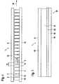
- FIG. 1shows the plan view of a band-shaped support material used as raw material
- FIG. 3shows the band-shaped support material with puncturing points punched out on its first face
- FIG. 4shows the puncturing points, covered by soft plastic strips, and a plastic material located opposite these and serving as a grip
- FIG. 5shows the application of a cover film and of a detection material between the silicone material and the plastic material on the top face of the band-shaped support material
- FIG. 6shows the plan view of an individual puncturing/measuring disposable body separated from the band-shaped support material and with covered puncturing point
- FIG. 7shows an individual puncturing/measuring disposable body with exposed puncturing point
- FIG. 8shows a cross section through the area of the individual puncturing/measuring disposable body, covered by the detection field, according to cross section line VIII-VIII, and
- FIG. 9shows a cross section through the individual puncturing/measuring disposable body according to FIG. 7 , according to cross section line IX-IX, the groove or notch having a triangular base.
- FIG. 1shows a band-shaped support material serving as an inert support body.
- a band-shaped support material 1which is preferably designed as a thin metal film with a thickness of between 0.1 and 0.3 mm, has a height h, and a length designated by 1.
- the band-shaped support material 1 configured as a thin metal filmcan be received on a winding reel and is unwound continuously from a store of material during the production of individual lancets.
- the height h of the band-shaped support material 1is chosen such that it corresponds at least to the later overall height of an individual puncturing/measuring disposable body 6 to be produced (cf. FIGS. 6 and 7 ).
- the depressions 2 embossed in the band-shaped support material 1extend continuously from a first face 9 to a second face 10 of the band-shaped support material 1 .
- virtual separating lines 5are provided which each extend between two depressions 2 embossed from the first face 9 and to the second face 10 of the band-shaped support material 1 .
- the individual puncturing/measuring disposable body 6which is later obtained, and which is separated from the band-shaped support material 1 along the separating lines 5 shown in FIG. 2 , comprises a first lancet part 7 and a second lancet part 8 between which the depression 2 extends, preferably in the axis of symmetry of the individual puncturing/measuring disposable body 6 .
- FIG. 3shows the production of recesses which delimit puncturing points on a first face of the band-shaped support material. If necessary, the height h of the test band can at the same time be shortened in this method step.
- recesses 11are produced on the first face 9 of the band-shaped support material 1 .
- the recesses 11can, as is shown in FIG. 3 , be made triangular, for example.
- the point of the recesses 11 directed away from the first face 9preferably coincides with the separating line 5 according to the view in FIG. 2 .
- the recesses 11are delimited by a first edge 14 and a second edge 15 .
- the intersection of edges 14 , 15defines a puncturing point 16 .
- the puncturing point 16can further be ground so that it is able to pierce human skin in order to collect a volume of blood.
- the separating lines 5along which the individual puncturing/measuring disposable bodies 6 are later separated from the band-shaped support material 1 , are provided in a division 12 .
- the division 12 and the spacing of the depressions 2is dependent on the later width of the individual puncturing/measuring disposable bodies 6 to be produced and can be chosen freely. After the production, shown in FIG. 3 , of recesses 11 on the first face 9 of the band-shaped support material 1 , a further processing of the band-shaped support material 1 takes place.
- Plastic cover 19is likewise applied.
- Plastic cover 19may be made of any suitable plastic material and serves for easier handling of the band-shaped support material 1 . Accordingly, harder materials are preferably used.
- the plastic cover 19can be used as a grip area 20 .
- the plan view according to FIG. 4shows the areas of the depressions 2 which extend between the soft plastic cover 18 at the first face 9 and the plastic cover 19 at the second face 10 of the band-shaped support material 1 .
- the separating line 5along which individual puncturing/measuring disposable bodies 6 are separated from the band-shaped support material 1 , is flush with the tip of the recesses 11 which were produced at the first face 9 of the band-shaped support material 1 , which define the puncturing points 16 on both sides of the depressions 2 (see view according to FIG. 3 ).
- the detection element 22is configured in the manner described in German patent application DE 196 29 656 A1, the disclosure of which is expressly incorporated by reference herein, for example, and can be used for the detection of glucose in human blood.
- the detection element 22is applied to the band-shaped support material 1 after the latter has been sterilized by ⁇ or ⁇ irradiation. Applying the detection element 22 afterwards has the advantage that the radiation-sensitive detection element 22 is not exposed to the sterilizing ( ⁇ or ⁇ radiation, since such irradiation could greatly impair the functioning or efficacy of the detection element 22 .
- the process steps of sterilization and of application of a radiation-sensitive detection element 22are distinct from one another, so that the detection element 22 is not impaired by the process step of sterilization by ⁇ or ⁇ radiation.
- the areas of the depressions 2 still open in the band-shaped support material I in FIG. 4are covered both by the cover film 21 and also by the detection element 22 and are no longer visible in the view according to FIG. 5 .
- the depressionsextend from the first face 9 to the second face 10 of the band-shaped support material 1 underneath the cover film 21 and underneath the detection element 22 .
- the view according to FIG. 6shows an individual puncturing/measuring disposable body 6 with covered puncturing point 16 .
- the individual puncturing/measuring disposable bodies 6are separated from the band-shaped support material 1 along the separating lines 5 shown in FIGS. 2 , 3 and 4 .
- These bodiescomprise, on both sides of the depression 2 , which serves as capillary channel 23 , a first lancet part 7 and a second lancet part 8 .
- the separation of the individual puncturing/measuring disposable bodies 6 from the band-shaped support material 1 transported in the direction of advance 39forms a first separating site 24 on the first lancet part 7 and a second separating site 25 on the second lancet part 8 .
- the depression 2 suitable for capillary liquid transportlies underneath the cover film 21 and underneath the detection element 22 .
- the latteris provided with a portion of the plastic cover 19 , which can function as a grip area 20 .
- the first face 9 of the individual puncturing/measuring disposable body 6 shown hereis covered by the soft plastic cover 18 .
- FIG. 7shows an individual puncturing/measuring disposable body 6 with soft plastic cover 18 removed.
- the depression 2which can be formed like a groove or notch in the band-shaped support material 1 , ends directly at the puncturing point 16 .
- the puncturing point 16can have a ground front part similar to an injection needle.
- a capillary channel mouth 27 of the depression 2opens out in the puncture point 16 .
- the depression 2which serves as capillary channel 23 for capillary liquid transport, is formed with a capillary channel length 38 .
- the width of the depressionis indicated by reference number 37 and depends on the configuration of the punching or embossing tool with which the depressions 2 are produced in the band-shaped support material 1 .
- FIG. 8shows a cross section, according to the cross section line VIII-VIII in FIG. 7 , through a capillary channel designed with a rounded depression base and suitable for liquid transport.
- the band-shaped support material 1is covered by the detection element 22 in the cross-sectional plane.
- the detection element 22has a thickness 28 .
- the thickness of the band-shaped support material 1preferably configured as a thin metal film with a thickness of 0.1 to 0.3 mm, is indicated by reference number 30 .
- the base 4 of the depression 2is designed with a rounded shape 34 .
- a supply of liquidfor example human blood, is taken up by the capillary channel 23 extending perpendicular to the plane of the drawing in FIG. 8 and suitable for capillary liquid transport. This channel merges into the detection element 22 and forms, in the latter, a saturated zone 33 .
- the supply of liquid 32 that can be taken up in the depression 2 and the capillary channel 23depends on the depth of the depression 2 , i.e. on the depth of embossing into the band-shaped support material 1 . With a capillary channel length 38 of approximately 15 mm and a capillary channel width 37 of approximately 0.25 mm, ca.
- 100 nl of human bloodcan be taken up in the capillary channel, on condition that the base 4 of the depression 2 has a rounded shape 34 .
- the time needed for a sufficient volume of liquid to pass into the depression 2 functioning as capillary channel 23 and located underneath the cover film 21 and the detection element 22depends on the configuration of that surface of the band-shaped support material 1 forming the capillary base and on the materials used for cover film 21 and detection element 22 . If aluminium, for example, is chosen, its oxidized surface can be made highly hydrophilic.
- a corresponding supply of liquidcan pass by capillary action under the cover film 21 and detection element 22 and wet the detection element portion 22 on the individual puncturing/measuring disposable body 6 .
- the individual puncturing/measuring disposable body 6 shown in FIGS. 6 and 7can be separated singly from the band-shaped support material 1 ; in addition to this, it is also possible, by batchwise perforation, to separate groups of 5 or 10 individual puncturing/measuring disposable bodies 6 from the band-shaped support material 1 . If the individual puncturing/measuring disposable bodies 6 are separated in batches or groups, individual perforations can be produced along the virtual separating line 5 , said perforations permitting easy separation of the outer-lying individual puncturing/measuring disposable body 6 from the respective batch.
- the individual puncturing/measuring disposable body 6 obtained by the production method proposed according to the inventionrepresents a combined puncturing and measuring device whose puncturing point 16 is formed in the band-shaped support material 1 by embossing and whose measuring function is produced in the same production method by applying the detection element 22 , with a cover film 21 covering the depressions 2 .
- the band-shaped support material 1can also be coated with a cover film 21 containing the detection element 22 , so that the detection element 22 is situated near the puncturing point 16 formed at one face of the band-shaped support material.
- the detection element 22is applied in the area of the sharpened or ground puncturing point 16 , the detection element 22 is wetted directly after insertion of the individual puncturing/measuring disposable body 6 into the human skin.
- the soft plastic cover 18 surrounding the puncturing points 16 and preferably made of a silicone materialis removed manually from the puncturing point 16 without leaving any residues.
- Removing the soft plastic material cover 18 from the puncturing point 16 without leaving any residesensures wetting of a detection element 22 applied in the area of the puncturing point 16 or, on the other hand, unimpeded entry of a liquid into the depression 2 , 23 which allows capillary liquid transport and can be embossed into the individual puncturing/measuring disposable body 6 .
- a hydrophilic plasticcan be selected for covering the puncturing points 16 , so that any residues possibly remaining in the area of the puncturing points 16 do not interfere with the wetting behaviour of the sample.
- the removal of the soft plastic cover 18may also be automated using a measurement system, for example if the measurement system comprises an apparatus with a magazine for receiving the combined puncturing and measuring devices proposed according to the invention for detection of an analyte in liquid.
- the wetting of the combined puncturing and measuring deviceit should be noted that the wetting of the combined puncturing and measuring device takes place in a separate step following the production of a skin incision, by guiding the puncturing point 16 to a drop of blood formed on the skin surface.
- the puncturing point 16 of the combined puncturing and measuring devicecan also be guided repeatedly to the drop of blood and inserted repeatedly into the skin incision, in order to achieve contact between the emerging body fluid, for example blood, and the depression 2 , 23 forming a capillary channel or the detection element 22 or the combined puncturing and measuring device.
Landscapes
- Health & Medical Sciences (AREA)
- Life Sciences & Earth Sciences (AREA)
- General Health & Medical Sciences (AREA)
- Engineering & Computer Science (AREA)
- Hematology (AREA)
- Veterinary Medicine (AREA)
- Public Health (AREA)
- Animal Behavior & Ethology (AREA)
- Surgery (AREA)
- Chemical & Material Sciences (AREA)
- Medical Informatics (AREA)
- Molecular Biology (AREA)
- Biomedical Technology (AREA)
- Pathology (AREA)
- Biophysics (AREA)
- Physics & Mathematics (AREA)
- Heart & Thoracic Surgery (AREA)
- Manufacturing & Machinery (AREA)
- Analytical Chemistry (AREA)
- Clinical Laboratory Science (AREA)
- Chemical Kinetics & Catalysis (AREA)
- Dispersion Chemistry (AREA)
- Epidemiology (AREA)
- Dermatology (AREA)
- Measurement Of The Respiration, Hearing Ability, Form, And Blood Characteristics Of Living Organisms (AREA)
Abstract
Description
Claims (22)
Applications Claiming Priority (4)
| Application Number | Priority Date | Filing Date | Title |
|---|---|---|---|
| DE10315544ADE10315544B4 (en) | 2003-04-04 | 2003-04-04 | Method for producing a piercing and measuring device and device |
| DE10315544 | 2003-04-04 | ||
| DE10315544.9 | 2003-04-04 | ||
| PCT/EP2004/003441WO2004086970A1 (en) | 2003-04-04 | 2004-04-01 | Method for producing a puncturing and measuring device |
Publications (2)
| Publication Number | Publication Date |
|---|---|
| US20060196031A1 US20060196031A1 (en) | 2006-09-07 |
| US8015685B2true US8015685B2 (en) | 2011-09-13 |
Family
ID=33016160
Family Applications (1)
| Application Number | Title | Priority Date | Filing Date |
|---|---|---|---|
| US10/552,089Expired - Fee RelatedUS8015685B2 (en) | 2003-04-04 | 2004-04-01 | Method for producing a puncturing and measuring device |
Country Status (3)
| Country | Link |
|---|---|
| US (1) | US8015685B2 (en) |
| DE (1) | DE10315544B4 (en) |
| WO (1) | WO2004086970A1 (en) |
Cited By (1)
| Publication number | Priority date | Publication date | Assignee | Title |
|---|---|---|---|---|
| US20110010929A1 (en)* | 2006-11-14 | 2011-01-20 | Guay Matthew J | Systems for producing assemblies |
Families Citing this family (83)
| Publication number | Priority date | Publication date | Assignee | Title |
|---|---|---|---|---|
| US6036924A (en) | 1997-12-04 | 2000-03-14 | Hewlett-Packard Company | Cassette of lancet cartridges for sampling blood |
| US6391005B1 (en) | 1998-03-30 | 2002-05-21 | Agilent Technologies, Inc. | Apparatus and method for penetration with shaft having a sensor for sensing penetration depth |
| DE10057832C1 (en) | 2000-11-21 | 2002-02-21 | Hartmann Paul Ag | Blood analysis device has syringe mounted in casing, annular mounting carrying needles mounted behind test strip and being swiveled so that needle can be pushed through strip and aperture in casing to take blood sample |
| US8641644B2 (en) | 2000-11-21 | 2014-02-04 | Sanofi-Aventis Deutschland Gmbh | Blood testing apparatus having a rotatable cartridge with multiple lancing elements and testing means |
| US7344507B2 (en) | 2002-04-19 | 2008-03-18 | Pelikan Technologies, Inc. | Method and apparatus for lancet actuation |
| JP4209767B2 (en) | 2001-06-12 | 2009-01-14 | ペリカン テクノロジーズ インコーポレイテッド | Self-optimized cutting instrument with adaptive means for temporary changes in skin properties |
| JP4272051B2 (en) | 2001-06-12 | 2009-06-03 | ペリカン テクノロジーズ インコーポレイテッド | Blood sampling apparatus and method |
| WO2002101359A2 (en) | 2001-06-12 | 2002-12-19 | Pelikan Technologies, Inc. | Integrated blood sampling analysis system with multi-use sampling module |
| US9427532B2 (en) | 2001-06-12 | 2016-08-30 | Sanofi-Aventis Deutschland Gmbh | Tissue penetration device |
| US9226699B2 (en) | 2002-04-19 | 2016-01-05 | Sanofi-Aventis Deutschland Gmbh | Body fluid sampling module with a continuous compression tissue interface surface |
| US7981056B2 (en) | 2002-04-19 | 2011-07-19 | Pelikan Technologies, Inc. | Methods and apparatus for lancet actuation |
| US9795747B2 (en) | 2010-06-02 | 2017-10-24 | Sanofi-Aventis Deutschland Gmbh | Methods and apparatus for lancet actuation |
| US7041068B2 (en) | 2001-06-12 | 2006-05-09 | Pelikan Technologies, Inc. | Sampling module device and method |
| EP1395185B1 (en) | 2001-06-12 | 2010-10-27 | Pelikan Technologies Inc. | Electric lancet actuator |
| US8337419B2 (en) | 2002-04-19 | 2012-12-25 | Sanofi-Aventis Deutschland Gmbh | Tissue penetration device |
| AU2002344825A1 (en) | 2001-06-12 | 2002-12-23 | Pelikan Technologies, Inc. | Method and apparatus for improving success rate of blood yield from a fingerstick |
| US7749174B2 (en) | 2001-06-12 | 2010-07-06 | Pelikan Technologies, Inc. | Method and apparatus for lancet launching device intergrated onto a blood-sampling cartridge |
| US7344894B2 (en) | 2001-10-16 | 2008-03-18 | Agilent Technologies, Inc. | Thermal regulation of fluidic samples within a diagnostic cartridge |
| US7909778B2 (en) | 2002-04-19 | 2011-03-22 | Pelikan Technologies, Inc. | Method and apparatus for penetrating tissue |
| US7141058B2 (en) | 2002-04-19 | 2006-11-28 | Pelikan Technologies, Inc. | Method and apparatus for a body fluid sampling device using illumination |
| US8267870B2 (en) | 2002-04-19 | 2012-09-18 | Sanofi-Aventis Deutschland Gmbh | Method and apparatus for body fluid sampling with hybrid actuation |
| US7582099B2 (en) | 2002-04-19 | 2009-09-01 | Pelikan Technologies, Inc | Method and apparatus for penetrating tissue |
| US7481776B2 (en) | 2002-04-19 | 2009-01-27 | Pelikan Technologies, Inc. | Method and apparatus for penetrating tissue |
| US9795334B2 (en) | 2002-04-19 | 2017-10-24 | Sanofi-Aventis Deutschland Gmbh | Method and apparatus for penetrating tissue |
| US7229458B2 (en) | 2002-04-19 | 2007-06-12 | Pelikan Technologies, Inc. | Method and apparatus for penetrating tissue |
| US8221334B2 (en) | 2002-04-19 | 2012-07-17 | Sanofi-Aventis Deutschland Gmbh | Method and apparatus for penetrating tissue |
| US7524293B2 (en) | 2002-04-19 | 2009-04-28 | Pelikan Technologies, Inc. | Method and apparatus for penetrating tissue |
| US7563232B2 (en) | 2002-04-19 | 2009-07-21 | Pelikan Technologies, Inc. | Method and apparatus for penetrating tissue |
| US7717863B2 (en) | 2002-04-19 | 2010-05-18 | Pelikan Technologies, Inc. | Method and apparatus for penetrating tissue |
| US7232451B2 (en) | 2002-04-19 | 2007-06-19 | Pelikan Technologies, Inc. | Method and apparatus for penetrating tissue |
| US7491178B2 (en) | 2002-04-19 | 2009-02-17 | Pelikan Technologies, Inc. | Method and apparatus for penetrating tissue |
| US9248267B2 (en) | 2002-04-19 | 2016-02-02 | Sanofi-Aventis Deustchland Gmbh | Tissue penetration device |
| US7648468B2 (en) | 2002-04-19 | 2010-01-19 | Pelikon Technologies, Inc. | Method and apparatus for penetrating tissue |
| US7674232B2 (en) | 2002-04-19 | 2010-03-09 | Pelikan Technologies, Inc. | Method and apparatus for penetrating tissue |
| US7371247B2 (en) | 2002-04-19 | 2008-05-13 | Pelikan Technologies, Inc | Method and apparatus for penetrating tissue |
| US7976476B2 (en) | 2002-04-19 | 2011-07-12 | Pelikan Technologies, Inc. | Device and method for variable speed lancet |
| US7331931B2 (en) | 2002-04-19 | 2008-02-19 | Pelikan Technologies, Inc. | Method and apparatus for penetrating tissue |
| US7410468B2 (en) | 2002-04-19 | 2008-08-12 | Pelikan Technologies, Inc. | Method and apparatus for penetrating tissue |
| US8784335B2 (en) | 2002-04-19 | 2014-07-22 | Sanofi-Aventis Deutschland Gmbh | Body fluid sampling device with a capacitive sensor |
| US7892183B2 (en) | 2002-04-19 | 2011-02-22 | Pelikan Technologies, Inc. | Method and apparatus for body fluid sampling and analyte sensing |
| US7374544B2 (en) | 2002-04-19 | 2008-05-20 | Pelikan Technologies, Inc. | Method and apparatus for penetrating tissue |
| US7708701B2 (en) | 2002-04-19 | 2010-05-04 | Pelikan Technologies, Inc. | Method and apparatus for a multi-use body fluid sampling device |
| US7547287B2 (en) | 2002-04-19 | 2009-06-16 | Pelikan Technologies, Inc. | Method and apparatus for penetrating tissue |
| US8702624B2 (en) | 2006-09-29 | 2014-04-22 | Sanofi-Aventis Deutschland Gmbh | Analyte measurement device with a single shot actuator |
| US7291117B2 (en) | 2002-04-19 | 2007-11-06 | Pelikan Technologies, Inc. | Method and apparatus for penetrating tissue |
| US7297122B2 (en) | 2002-04-19 | 2007-11-20 | Pelikan Technologies, Inc. | Method and apparatus for penetrating tissue |
| US7901362B2 (en) | 2002-04-19 | 2011-03-08 | Pelikan Technologies, Inc. | Method and apparatus for penetrating tissue |
| US9314194B2 (en) | 2002-04-19 | 2016-04-19 | Sanofi-Aventis Deutschland Gmbh | Tissue penetration device |
| US8579831B2 (en) | 2002-04-19 | 2013-11-12 | Sanofi-Aventis Deutschland Gmbh | Method and apparatus for penetrating tissue |
| US7815579B2 (en) | 2005-03-02 | 2010-10-19 | Roche Diagnostics Operations, Inc. | Dynamic integrated lancing test strip with sterility cover |
| US7214200B2 (en) | 2002-12-30 | 2007-05-08 | Roche Diagnostics Operations, Inc. | Integrated analytical test element |
| US8574895B2 (en) | 2002-12-30 | 2013-11-05 | Sanofi-Aventis Deutschland Gmbh | Method and apparatus using optical techniques to measure analyte levels |
| US7211052B2 (en) | 2002-12-30 | 2007-05-01 | Roche Diagnostics Operations, Inc. | Flexible test strip lancet device |
| US7850621B2 (en) | 2003-06-06 | 2010-12-14 | Pelikan Technologies, Inc. | Method and apparatus for body fluid sampling and analyte sensing |
| WO2006001797A1 (en) | 2004-06-14 | 2006-01-05 | Pelikan Technologies, Inc. | Low pain penetrating |
| EP1635700B1 (en) | 2003-06-13 | 2016-03-09 | Sanofi-Aventis Deutschland GmbH | Apparatus for a point of care device |
| US7920906B2 (en) | 2005-03-10 | 2011-04-05 | Dexcom, Inc. | System and methods for processing analyte sensor data for sensor calibration |
| US8282576B2 (en) | 2003-09-29 | 2012-10-09 | Sanofi-Aventis Deutschland Gmbh | Method and apparatus for an improved sample capture device |
| EP1680014A4 (en) | 2003-10-14 | 2009-01-21 | Pelikan Technologies Inc | METHOD AND DEVICE FOR A VARIABLE USER INTERFACE |
| US9247900B2 (en) | 2004-07-13 | 2016-02-02 | Dexcom, Inc. | Analyte sensor |
| US8668656B2 (en) | 2003-12-31 | 2014-03-11 | Sanofi-Aventis Deutschland Gmbh | Method and apparatus for improving fluidic flow and sample capture |
| US7822454B1 (en) | 2005-01-03 | 2010-10-26 | Pelikan Technologies, Inc. | Fluid sampling device with improved analyte detecting member configuration |
| WO2006011062A2 (en) | 2004-05-20 | 2006-02-02 | Albatros Technologies Gmbh & Co. Kg | Printable hydrogel for biosensors |
| WO2005120365A1 (en) | 2004-06-03 | 2005-12-22 | Pelikan Technologies, Inc. | Method and apparatus for a fluid sampling device |
| US20070045902A1 (en) | 2004-07-13 | 2007-03-01 | Brauker James H | Analyte sensor |
| US7654956B2 (en) | 2004-07-13 | 2010-02-02 | Dexcom, Inc. | Transcutaneous analyte sensor |
| US7488298B2 (en) | 2004-10-08 | 2009-02-10 | Roche Diagnostics Operations, Inc. | Integrated lancing test strip with capillary transfer sheet |
| DE102004058164B4 (en)* | 2004-12-02 | 2009-04-16 | Roche Diagnostics Gmbh | Lancing device for taking blood and method for the preparation thereof |
| US8652831B2 (en) | 2004-12-30 | 2014-02-18 | Sanofi-Aventis Deutschland Gmbh | Method and apparatus for analyte measurement test time |
| US7479118B2 (en)* | 2005-02-07 | 2009-01-20 | Roche Diagnostics Operations, Inc. | Lancet protective cap |
| EP1868491B1 (en) | 2005-03-24 | 2011-05-18 | Roche Diagnostics GmbH | Analyzing means with lancet and test element |
| KR100778080B1 (en)* | 2006-06-22 | 2007-11-21 | 주식회사 인켈 | Repeater without SAR filter using high sampling frequency of digital signal processor |
| EP1878387B1 (en) | 2006-07-15 | 2010-11-24 | Roche Diagnostics GmbH | Lancet, lancet feeder belt and pricking device for creating a puncture wound |
| EP1878386A1 (en)* | 2006-07-15 | 2008-01-16 | Roche Diagnostics GmbH | Process to produce lancet; lancet, lancet band and device for pricking the skin |
| US7766846B2 (en)* | 2008-01-28 | 2010-08-03 | Roche Diagnostics Operations, Inc. | Rapid blood expression and sampling |
| EP2265324B1 (en) | 2008-04-11 | 2015-01-28 | Sanofi-Aventis Deutschland GmbH | Integrated analyte measurement system |
| EP2130493B1 (en)* | 2008-06-07 | 2013-09-25 | Roche Diagnostics GmbH | Analysis system for detecting an analyte in a bodily fluid, cartridge for an analytic device and method for manufacturing a cartridge for an analysis system. |
| US9375169B2 (en) | 2009-01-30 | 2016-06-28 | Sanofi-Aventis Deutschland Gmbh | Cam drive for managing disposable penetrating member actions with a single motor and motor and control system |
| EP2229886A1 (en)* | 2009-03-17 | 2010-09-22 | Roche Diagnostics GmbH | Lance with plastic attachment element |
| EP2241252A1 (en)* | 2009-03-17 | 2010-10-20 | F. Hoffmann-La Roche AG | Testing device, in particular for blood sugar tests |
| US8965476B2 (en) | 2010-04-16 | 2015-02-24 | Sanofi-Aventis Deutschland Gmbh | Tissue penetration device |
| ES2533179T3 (en)* | 2010-12-27 | 2015-04-08 | F. Hoffmann-La Roche Ag | Container made of a composite material of aluminum and polymer sheets for analytical auxiliary media and method of production thereof |
| EP2811299A1 (en) | 2013-06-07 | 2014-12-10 | Roche Diagniostics GmbH | Test element for detecting at least one analyte in a body fluid |
Citations (37)
| Publication number | Priority date | Publication date | Assignee | Title |
|---|---|---|---|---|
| US2801633A (en)* | 1954-02-17 | 1957-08-06 | Joseph C Ehrlich | Lancets |
| US2896628A (en)* | 1957-06-12 | 1959-07-28 | Propper Mfg Company Inc | Blood lancets |
| US3046987A (en)* | 1957-06-05 | 1962-07-31 | Joseph C Ehrlich | Disposable lancet |
| US3517670A (en)* | 1967-11-09 | 1970-06-30 | Propper Mfg Co Inc | Blood-letting lancet |
| US3665672A (en)* | 1970-01-05 | 1972-05-30 | Propper Mfg Co Inc | Method and apparatus for manufacturing and packing lancets |
| US3822461A (en) | 1970-09-23 | 1974-07-09 | Swedish Hospital Supply Ab | Disposable lancet |
| EP0199484A2 (en) | 1985-04-08 | 1986-10-29 | Audio Bionics Inc | Medical system |
| US4924879A (en) | 1988-10-07 | 1990-05-15 | Brien Walter J O | Blood lancet device |
| US5397334A (en)* | 1994-01-11 | 1995-03-14 | Sherwood Medical Company | Distal movement limiting assembly for finger stick device |
| US5582184A (en) | 1993-10-13 | 1996-12-10 | Integ Incorporated | Interstitial fluid collection and constituent measurement |
| US5591139A (en) | 1994-06-06 | 1997-01-07 | The Regents Of The University Of California | IC-processed microneedles |
| US5680858A (en) | 1992-12-10 | 1997-10-28 | Novo Nordisk A/S | Method and apparatus for in vivo determination of the concentration in a body fluid of metabolically significant substances |
| WO1997042888A1 (en) | 1996-05-17 | 1997-11-20 | Mercury Diagnostics Inc. | Blood and interstitial fluid sampling device |
| US5755733A (en)* | 1994-11-29 | 1998-05-26 | Apls Co., Ltd. | Lancet assembly |
| US5801057A (en) | 1996-03-22 | 1998-09-01 | Smart; Wilson H. | Microsampling device and method of construction |
| EP0861670A2 (en) | 1997-02-01 | 1998-09-02 | Wagner, Wolfgang, Dr.med. | Puncture tip for stylus or test strip taking blood samples out of the skin of a living being, preferred process of its application and manufacturing |
| DE19846250A1 (en) | 1997-10-14 | 1999-04-29 | Hewlett Packard Co | Device and method for minimally invasive blood sampling |
| DE19753847A1 (en) | 1997-12-04 | 1999-06-10 | Roche Diagnostics Gmbh | Analytical test element with capillary channel |
| US5928207A (en) | 1997-06-30 | 1999-07-27 | The Regents Of The University Of California | Microneedle with isotropically etched tip, and method of fabricating such a device |
| US5951492A (en) | 1996-05-17 | 1999-09-14 | Mercury Diagnostics, Inc. | Methods and apparatus for sampling and analyzing body fluid |
| US6014577A (en) | 1995-12-19 | 2000-01-11 | Abbot Laboratories | Device for the detection of analyte and administration of a therapeutic substance |
| US6102927A (en) | 1999-04-30 | 2000-08-15 | Wright; George A. | Blood lancet and method of manufacture |
| US20040193202A1 (en)* | 2003-03-28 | 2004-09-30 | Allen John J. | Integrated lance and strip for analyte measurement |
| US20050021066A1 (en)* | 2001-08-29 | 2005-01-27 | Hans-Juergen Kuhr | Analytical device with lancet and test element |
| US20050131440A1 (en)* | 2003-12-11 | 2005-06-16 | Charles Starnes | Lancet |
| US7214200B2 (en)* | 2002-12-30 | 2007-05-08 | Roche Diagnostics Operations, Inc. | Integrated analytical test element |
| US7244264B2 (en)* | 2002-12-03 | 2007-07-17 | Roche Diagnostics Operations, Inc. | Dual blade lancing test strip |
| US20070219462A1 (en)* | 2002-04-19 | 2007-09-20 | Barry Briggs | Methods and apparatus for lancet actuation |
| US7303726B2 (en)* | 2002-05-09 | 2007-12-04 | Lifescan, Inc. | Minimal procedure analyte test system |
| US7322996B2 (en)* | 2002-05-31 | 2008-01-29 | Facet Technologies, Llc | Precisely guided lancet |
| US7374546B2 (en)* | 2003-01-29 | 2008-05-20 | Roche Diagnostics Operations, Inc. | Integrated lancing test strip |
| US7473264B2 (en)* | 2003-03-28 | 2009-01-06 | Lifescan, Inc. | Integrated lance and strip for analyte measurement |
| US20090010802A1 (en)* | 2002-12-27 | 2009-01-08 | Abner David Joseph | Method for manufacturing a sterilized lancet integrated biosensor |
| US7479118B2 (en)* | 2005-02-07 | 2009-01-20 | Roche Diagnostics Operations, Inc. | Lancet protective cap |
| US20090131964A1 (en)* | 2002-04-19 | 2009-05-21 | Dominique Freeman | Tissue penetration device |
| US7736322B2 (en)* | 2002-12-27 | 2010-06-15 | Roche Diagnostics Operations, Inc. | Precision depth control lancing tip |
| US7815579B2 (en)* | 2005-03-02 | 2010-10-19 | Roche Diagnostics Operations, Inc. | Dynamic integrated lancing test strip with sterility cover |
Family Cites Families (2)
| Publication number | Priority date | Publication date | Assignee | Title |
|---|---|---|---|---|
| DE10010694A1 (en)* | 2000-03-04 | 2001-09-06 | Roche Diagnostics Gmbh | Lancet including tipped needle with body surrounding tip |
| US20030143113A2 (en)* | 2002-05-09 | 2003-07-31 | Lifescan, Inc. | Physiological sample collection devices and methods of using the same |
- 2003
- 2003-04-04DEDE10315544Apatent/DE10315544B4/ennot_activeExpired - Fee Related
- 2004
- 2004-04-01USUS10/552,089patent/US8015685B2/ennot_activeExpired - Fee Related
- 2004-04-01WOPCT/EP2004/003441patent/WO2004086970A1/enactiveApplication Filing
Patent Citations (43)
| Publication number | Priority date | Publication date | Assignee | Title |
|---|---|---|---|---|
| US2801633A (en)* | 1954-02-17 | 1957-08-06 | Joseph C Ehrlich | Lancets |
| US3046987A (en)* | 1957-06-05 | 1962-07-31 | Joseph C Ehrlich | Disposable lancet |
| US2896628A (en)* | 1957-06-12 | 1959-07-28 | Propper Mfg Company Inc | Blood lancets |
| US3517670A (en)* | 1967-11-09 | 1970-06-30 | Propper Mfg Co Inc | Blood-letting lancet |
| US3665672A (en)* | 1970-01-05 | 1972-05-30 | Propper Mfg Co Inc | Method and apparatus for manufacturing and packing lancets |
| US3822461A (en) | 1970-09-23 | 1974-07-09 | Swedish Hospital Supply Ab | Disposable lancet |
| EP0199484A2 (en) | 1985-04-08 | 1986-10-29 | Audio Bionics Inc | Medical system |
| US4924879A (en) | 1988-10-07 | 1990-05-15 | Brien Walter J O | Blood lancet device |
| US5680858A (en) | 1992-12-10 | 1997-10-28 | Novo Nordisk A/S | Method and apparatus for in vivo determination of the concentration in a body fluid of metabolically significant substances |
| US5582184A (en) | 1993-10-13 | 1996-12-10 | Integ Incorporated | Interstitial fluid collection and constituent measurement |
| US5820570A (en) | 1993-10-13 | 1998-10-13 | Integ Incorporated | Interstitial fluid collection and constituent measurement |
| US5397334A (en)* | 1994-01-11 | 1995-03-14 | Sherwood Medical Company | Distal movement limiting assembly for finger stick device |
| US5591139A (en) | 1994-06-06 | 1997-01-07 | The Regents Of The University Of California | IC-processed microneedles |
| US5755733A (en)* | 1994-11-29 | 1998-05-26 | Apls Co., Ltd. | Lancet assembly |
| US6014577A (en) | 1995-12-19 | 2000-01-11 | Abbot Laboratories | Device for the detection of analyte and administration of a therapeutic substance |
| US5801057A (en) | 1996-03-22 | 1998-09-01 | Smart; Wilson H. | Microsampling device and method of construction |
| WO1997042888A1 (en) | 1996-05-17 | 1997-11-20 | Mercury Diagnostics Inc. | Blood and interstitial fluid sampling device |
| US5951492A (en) | 1996-05-17 | 1999-09-14 | Mercury Diagnostics, Inc. | Methods and apparatus for sampling and analyzing body fluid |
| EP0861670A2 (en) | 1997-02-01 | 1998-09-02 | Wagner, Wolfgang, Dr.med. | Puncture tip for stylus or test strip taking blood samples out of the skin of a living being, preferred process of its application and manufacturing |
| US5928207A (en) | 1997-06-30 | 1999-07-27 | The Regents Of The University Of California | Microneedle with isotropically etched tip, and method of fabricating such a device |
| DE19846250A1 (en) | 1997-10-14 | 1999-04-29 | Hewlett Packard Co | Device and method for minimally invasive blood sampling |
| CA2311496A1 (en) | 1997-12-04 | 1999-06-17 | Roche Diagnostics Gmbh | Analytic test element with a capillary canal |
| DE19753847A1 (en) | 1997-12-04 | 1999-06-10 | Roche Diagnostics Gmbh | Analytical test element with capillary channel |
| US6102927A (en) | 1999-04-30 | 2000-08-15 | Wright; George A. | Blood lancet and method of manufacture |
| US7396334B2 (en)* | 2001-08-29 | 2008-07-08 | Roche Diagnostics Operations, Inc. | Analytical device with lancet and test element |
| US20050021066A1 (en)* | 2001-08-29 | 2005-01-27 | Hans-Juergen Kuhr | Analytical device with lancet and test element |
| US20070219462A1 (en)* | 2002-04-19 | 2007-09-20 | Barry Briggs | Methods and apparatus for lancet actuation |
| US20090131964A1 (en)* | 2002-04-19 | 2009-05-21 | Dominique Freeman | Tissue penetration device |
| US7303726B2 (en)* | 2002-05-09 | 2007-12-04 | Lifescan, Inc. | Minimal procedure analyte test system |
| US7322996B2 (en)* | 2002-05-31 | 2008-01-29 | Facet Technologies, Llc | Precisely guided lancet |
| US7244264B2 (en)* | 2002-12-03 | 2007-07-17 | Roche Diagnostics Operations, Inc. | Dual blade lancing test strip |
| US20090010802A1 (en)* | 2002-12-27 | 2009-01-08 | Abner David Joseph | Method for manufacturing a sterilized lancet integrated biosensor |
| US7736322B2 (en)* | 2002-12-27 | 2010-06-15 | Roche Diagnostics Operations, Inc. | Precision depth control lancing tip |
| US20070191738A1 (en)* | 2002-12-30 | 2007-08-16 | Raney Charles C | Integrated analytical test element |
| US7214200B2 (en)* | 2002-12-30 | 2007-05-08 | Roche Diagnostics Operations, Inc. | Integrated analytical test element |
| US7374546B2 (en)* | 2003-01-29 | 2008-05-20 | Roche Diagnostics Operations, Inc. | Integrated lancing test strip |
| US7169117B2 (en)* | 2003-03-28 | 2007-01-30 | Lifescan, Inc. | Integrated lance and strip for analyte measurement |
| US20040193202A1 (en)* | 2003-03-28 | 2004-09-30 | Allen John J. | Integrated lance and strip for analyte measurement |
| US7473264B2 (en)* | 2003-03-28 | 2009-01-06 | Lifescan, Inc. | Integrated lance and strip for analyte measurement |
| US20050131440A1 (en)* | 2003-12-11 | 2005-06-16 | Charles Starnes | Lancet |
| US7479118B2 (en)* | 2005-02-07 | 2009-01-20 | Roche Diagnostics Operations, Inc. | Lancet protective cap |
| US20090124933A1 (en)* | 2005-02-07 | 2009-05-14 | Chan Frank A | Lancet protective cap |
| US7815579B2 (en)* | 2005-03-02 | 2010-10-19 | Roche Diagnostics Operations, Inc. | Dynamic integrated lancing test strip with sterility cover |
Cited By (1)
| Publication number | Priority date | Publication date | Assignee | Title |
|---|---|---|---|---|
| US20110010929A1 (en)* | 2006-11-14 | 2011-01-20 | Guay Matthew J | Systems for producing assemblies |
Also Published As
| Publication number | Publication date |
|---|---|
| DE10315544B4 (en) | 2007-02-15 |
| US20060196031A1 (en) | 2006-09-07 |
| WO2004086970A1 (en) | 2004-10-14 |
| DE10315544A1 (en) | 2004-10-21 |
Similar Documents
| Publication | Publication Date | Title |
|---|---|---|
| US8015685B2 (en) | Method for producing a puncturing and measuring device | |
| CN102573631B (en) | Body fluid lancing, acquisition and test cartridge design | |
| JP3339836B2 (en) | Method for manufacturing analytical device | |
| EP1287785B1 (en) | Analyzing means with lancet and test element | |
| US7060192B2 (en) | Methods of fabricating physiological sample collection devices | |
| EP1982644B1 (en) | Analytical system for detecting an analyte in a body fluid and disposable integrated puncturing and analyzing element | |
| US20100113977A1 (en) | Integrated disposable for automatic or manual blood dosing | |
| EP1818014A1 (en) | Test element with elastically supported lancet | |
| AU2012242469B2 (en) | Sample capture in one step for test strips | |
| CN101312690A (en) | Kinked lancet | |
| KR101223382B1 (en) | Joining foils with laser for sterile lancets | |
| US20110108190A1 (en) | Method for producing a tape product having diagnostic aids | |
| CN101489484B (en) | Multi-lancet device | |
| JP4402221B2 (en) | Strip-shaped electrochemical sensor | |
| EP2210558A1 (en) | Lancet with capillary canal and sterile protection and method for producing such a lancet | |
| HK1133376A (en) | Multi-use lancing device with lancets for bodily fluid sampling supplied on a tape | |
| HK1106991A1 (en) | Multi-use lancing device with lancets for bodily fluid sampling supplied on a tape | |
| HK1106991B (en) | Multi-use lancing device with lancets for bodily fluid sampling supplied on a tape | |
| AU2015200584A1 (en) | Sample capture in one step for test strips | |
| HK1140400A1 (en) | Analytical system for determining an analyte in a body fluid and disposable integrated sample collection and analytical element | |
| HK1167795B (en) | Optimized lancet strip | |
| HK1140400B (en) | Analytical system for determining an analyte in a body fluid and disposable integrated sample collection and analytical element | |
| HK1167795A1 (en) | Optimized lancet strip |
Legal Events
| Date | Code | Title | Description |
|---|---|---|---|
| AS | Assignment | Owner name:ROCHE DIAGNOSTICS GMBH, GERMANY Free format text:ASSIGNMENT OF ASSIGNORS INTEREST;ASSIGNORS:HOENES, JOACHIM;ZIMMER, VOLKER;SIGNING DATES FROM 20060109 TO 20060110;REEL/FRAME:018672/0691 Owner name:ROCHE DIAGNOSTICS OPERATIONS, INC., INDIANA Free format text:ASSIGNMENT OF ASSIGNORS INTEREST;ASSIGNOR:ROCHE DIAGNOSTICS GMBH;REEL/FRAME:018672/0726 Effective date:20060109 Owner name:ROCHE DIAGNOSTICS GMBH, GERMANY Free format text:ASSIGNMENT OF ASSIGNORS INTEREST;ASSIGNORS:HOENES, JOACHIM;ZIMMER, VOLKER;REEL/FRAME:018672/0691;SIGNING DATES FROM 20060109 TO 20060110 | |
| ZAAA | Notice of allowance and fees due | Free format text:ORIGINAL CODE: NOA | |
| ZAAB | Notice of allowance mailed | Free format text:ORIGINAL CODE: MN/=. | |
| ZAAA | Notice of allowance and fees due | Free format text:ORIGINAL CODE: NOA | |
| ZAAB | Notice of allowance mailed | Free format text:ORIGINAL CODE: MN/=. | |
| STCF | Information on status: patent grant | Free format text:PATENTED CASE | |
| FPAY | Fee payment | Year of fee payment:4 | |
| AS | Assignment | Owner name:ROCHE DIABETES CARE, INC., INDIANA Free format text:ASSIGNMENT OF ASSIGNORS INTEREST;ASSIGNOR:ROCHE DIAGNOSTICS OPERATIONS, INC.;REEL/FRAME:036008/0670 Effective date:20150302 | |
| MAFP | Maintenance fee payment | Free format text:PAYMENT OF MAINTENANCE FEE, 8TH YEAR, LARGE ENTITY (ORIGINAL EVENT CODE: M1552); ENTITY STATUS OF PATENT OWNER: LARGE ENTITY Year of fee payment:8 | |
| FEPP | Fee payment procedure | Free format text:MAINTENANCE FEE REMINDER MAILED (ORIGINAL EVENT CODE: REM.); ENTITY STATUS OF PATENT OWNER: LARGE ENTITY | |
| LAPS | Lapse for failure to pay maintenance fees | Free format text:PATENT EXPIRED FOR FAILURE TO PAY MAINTENANCE FEES (ORIGINAL EVENT CODE: EXP.); ENTITY STATUS OF PATENT OWNER: LARGE ENTITY | |
| STCH | Information on status: patent discontinuation | Free format text:PATENT EXPIRED DUE TO NONPAYMENT OF MAINTENANCE FEES UNDER 37 CFR 1.362 | |
| FP | Lapsed due to failure to pay maintenance fee | Effective date:20230913 |