US8014849B2 - Rotational markers - Google Patents
Rotational markersDownload PDFInfo
- Publication number
- US8014849B2 US8014849B2US10/719,421US71942103AUS8014849B2US 8014849 B2US8014849 B2US 8014849B2US 71942103 AUS71942103 AUS 71942103AUS 8014849 B2US8014849 B2US 8014849B2
- Authority
- US
- United States
- Prior art keywords
- medical device
- marker
- rotational
- longitudinal axis
- symbol
- Prior art date
- Legal status (The legal status is an assumption and is not a legal conclusion. Google has not performed a legal analysis and makes no representation as to the accuracy of the status listed.)
- Expired - Fee Related, expires
Links
- 239000003550markerSubstances0.000claimsabstractdescription203
- 238000003384imaging methodMethods0.000claimsabstractdescription35
- 239000000463materialSubstances0.000claimsdescription22
- 238000000034methodMethods0.000claimsdescription16
- 238000002679ablationMethods0.000claimsdescription8
- 230000036961partial effectEffects0.000claimsdescription3
- -1polyethylene terephthalatePolymers0.000description16
- 230000001419dependent effectEffects0.000description10
- 238000000576coating methodMethods0.000description9
- 229920001577copolymerPolymers0.000description7
- 206010002329AneurysmDiseases0.000description6
- WYTGDNHDOZPMIW-RCBQFDQVSA-NalstonineNatural productsC1=CC2=C3C=CC=CC3=NC2=C2N1C[C@H]1[C@H](C)OC=C(C(=O)OC)[C@H]1C2WYTGDNHDOZPMIW-RCBQFDQVSA-N0.000description6
- 102000004169proteins and genesHuman genes0.000description6
- 108090000623proteins and genesProteins0.000description6
- 239000003102growth factorSubstances0.000description5
- 229920000728polyesterPolymers0.000description5
- 229920000642polymerPolymers0.000description5
- KDLHZDBZIXYQEI-UHFFFAOYSA-NPalladiumChemical compound[Pd]KDLHZDBZIXYQEI-UHFFFAOYSA-N0.000description4
- 210000001367arteryAnatomy0.000description4
- 239000011248coating agentSubstances0.000description4
- 239000003814drugSubstances0.000description4
- 239000003112inhibitorSubstances0.000description4
- 239000000203mixtureSubstances0.000description4
- 229920000139polyethylene terephthalatePolymers0.000description4
- 239000005020polyethylene terephthalateSubstances0.000description4
- 108010049870Bone Morphogenetic Protein 7Proteins0.000description3
- 102100022544Bone morphogenetic protein 7Human genes0.000description3
- HTTJABKRGRZYRN-UHFFFAOYSA-NHeparinChemical compoundOC1C(NC(=O)C)C(O)OC(COS(O)(=O)=O)C1OC1C(OS(O)(=O)=O)C(O)C(OC2C(C(OS(O)(=O)=O)C(OC3C(C(O)C(O)C(O3)C(O)=O)OS(O)(=O)=O)C(CO)O2)NS(O)(=O)=O)C(C(O)=O)O1HTTJABKRGRZYRN-UHFFFAOYSA-N0.000description3
- 208000031481Pathologic ConstrictionDiseases0.000description3
- 239000004952PolyamideSubstances0.000description3
- 229920002614Polyether block amidePolymers0.000description3
- 239000004698PolyethyleneSubstances0.000description3
- 239000004721Polyphenylene oxideSubstances0.000description3
- 239000004743PolypropyleneSubstances0.000description3
- 239000003146anticoagulant agentSubstances0.000description3
- 239000003795chemical substances by applicationSubstances0.000description3
- 229920006248expandable polystyrenePolymers0.000description3
- 229920002647polyamidePolymers0.000description3
- 229920000573polyethylenePolymers0.000description3
- 229920006380polyphenylene oxidePolymers0.000description3
- 229920001155polypropylenePolymers0.000description3
- 229920001343polytetrafluoroethylenePolymers0.000description3
- 239000004810polytetrafluoroethyleneSubstances0.000description3
- 229920002635polyurethanePolymers0.000description3
- 239000004814polyurethaneSubstances0.000description3
- 208000037804stenosisDiseases0.000description3
- 230000036262stenosisEffects0.000description3
- 108020005544Antisense RNAProteins0.000description2
- BSYNRYMUTXBXSQ-UHFFFAOYSA-NAspirinChemical compoundCC(=O)OC1=CC=CC=C1C(O)=OBSYNRYMUTXBXSQ-UHFFFAOYSA-N0.000description2
- 108010049931Bone Morphogenetic Protein 2Proteins0.000description2
- 108010049951Bone Morphogenetic Protein 3Proteins0.000description2
- 108010049955Bone Morphogenetic Protein 4Proteins0.000description2
- 108010049976Bone Morphogenetic Protein 5Proteins0.000description2
- 108010049974Bone Morphogenetic Protein 6Proteins0.000description2
- 102100024506Bone morphogenetic protein 2Human genes0.000description2
- 102100024504Bone morphogenetic protein 3Human genes0.000description2
- 102100024505Bone morphogenetic protein 4Human genes0.000description2
- 102100022526Bone morphogenetic protein 5Human genes0.000description2
- 102100022525Bone morphogenetic protein 6Human genes0.000description2
- 108010035532CollagenProteins0.000description2
- 102000008186CollagenHuman genes0.000description2
- 101710112752CytotoxinProteins0.000description2
- 108020004414DNAProteins0.000description2
- 108010010803GelatinProteins0.000description2
- 229940123011Growth factor receptor antagonistDrugs0.000description2
- XEEYBQQBJWHFJM-UHFFFAOYSA-NIronChemical compound[Fe]XEEYBQQBJWHFJM-UHFFFAOYSA-N0.000description2
- JHWNWJKBPDFINM-UHFFFAOYSA-NLaurolactamChemical compoundO=C1CCCCCCCCCCCN1JHWNWJKBPDFINM-UHFFFAOYSA-N0.000description2
- 239000004677NylonSubstances0.000description2
- 229920000299Nylon 12Polymers0.000description2
- 229920000954PolyglycolidePolymers0.000description2
- 239000004734Polyphenylene sulfideSubstances0.000description2
- 229960001138acetylsalicylic acidDrugs0.000description2
- 239000000853adhesiveSubstances0.000description2
- 230000001070adhesive effectEffects0.000description2
- 229910045601alloyInorganic materials0.000description2
- 239000000956alloySubstances0.000description2
- 230000000702anti-platelet effectEffects0.000description2
- 230000001028anti-proliverative effectEffects0.000description2
- 239000004019antithrombinChemical class0.000description2
- 230000001588bifunctional effectEffects0.000description2
- 230000000903blocking effectEffects0.000description2
- 210000004204blood vesselAnatomy0.000description2
- 230000004663cell proliferationEffects0.000description2
- 229920001436collagenPolymers0.000description2
- 239000003184complementary RNASubstances0.000description2
- 150000001875compoundsChemical class0.000description2
- 230000008878couplingEffects0.000description2
- 238000010168coupling processMethods0.000description2
- 238000005859coupling reactionMethods0.000description2
- 231100000599cytotoxic agentToxicity0.000description2
- 239000002619cytotoxinSubstances0.000description2
- 230000002950deficientEffects0.000description2
- 229940079593drugDrugs0.000description2
- 238000002594fluoroscopyMethods0.000description2
- 229920000159gelatinPolymers0.000description2
- 239000008273gelatinSubstances0.000description2
- 235000019322gelatineNutrition0.000description2
- 235000011852gelatine dessertsNutrition0.000description2
- 150000004676glycansChemical class0.000description2
- 229920000669heparinPolymers0.000description2
- 229960002897heparinDrugs0.000description2
- 229910052741iridiumInorganic materials0.000description2
- GKOZUEZYRPOHIO-UHFFFAOYSA-Niridium atomChemical compound[Ir]GKOZUEZYRPOHIO-UHFFFAOYSA-N0.000description2
- 230000007246mechanismEffects0.000description2
- 229920001778nylonPolymers0.000description2
- 229910052763palladiumInorganic materials0.000description2
- BASFCYQUMIYNBI-UHFFFAOYSA-NplatinumChemical compound[Pt]BASFCYQUMIYNBI-UHFFFAOYSA-N0.000description2
- 229920001643poly(ether ketone)Polymers0.000description2
- 229920000747poly(lactic acid)Polymers0.000description2
- 229920001281polyalkylenePolymers0.000description2
- 229920001707polybutylene terephthalatePolymers0.000description2
- 229920001610polycaprolactonePolymers0.000description2
- 239000004632polycaprolactoneSubstances0.000description2
- 239000004417polycarbonateSubstances0.000description2
- 229920000515polycarbonatePolymers0.000description2
- 229920000570polyetherPolymers0.000description2
- 239000004633polyglycolic acidSubstances0.000description2
- 239000004626polylactic acidSubstances0.000description2
- 229920000098polyolefinPolymers0.000description2
- 229920000069polyphenylene sulfidePolymers0.000description2
- 229920001282polysaccharidePolymers0.000description2
- 239000005017polysaccharideSubstances0.000description2
- 229920001296polysiloxanePolymers0.000description2
- 229920002215polytrimethylene terephthalatePolymers0.000description2
- 229920000036polyvinylpyrrolidonePolymers0.000description2
- 235000013855polyvinylpyrrolidoneNutrition0.000description2
- 239000001267polyvinylpyrrolidoneSubstances0.000description2
- 102000004196processed proteins & peptidesHuman genes0.000description2
- 108090000765processed proteins & peptidesProteins0.000description2
- 229920000638styrene acrylonitrilePolymers0.000description2
- 229940124597therapeutic agentDrugs0.000description2
- 210000005167vascular cellAnatomy0.000description2
- KIUKXJAPPMFGSW-DNGZLQJQSA-N(2S,3S,4S,5R,6R)-6-[(2S,3R,4R,5S,6R)-3-Acetamido-2-[(2S,3S,4R,5R,6R)-6-[(2R,3R,4R,5S,6R)-3-acetamido-2,5-dihydroxy-6-(hydroxymethyl)oxan-4-yl]oxy-2-carboxy-4,5-dihydroxyoxan-3-yl]oxy-5-hydroxy-6-(hydroxymethyl)oxan-4-yl]oxy-3,4,5-trihydroxyoxane-2-carboxylic acidChemical compoundCC(=O)N[C@H]1[C@H](O)O[C@H](CO)[C@@H](O)[C@@H]1O[C@H]1[C@H](O)[C@@H](O)[C@H](O[C@H]2[C@@H]([C@@H](O[C@H]3[C@@H]([C@@H](O)[C@H](O)[C@H](O3)C(O)=O)O)[C@H](O)[C@@H](CO)O2)NC(C)=O)[C@@H](C(O)=O)O1KIUKXJAPPMFGSW-DNGZLQJQSA-N0.000description1
- PUDHBTGHUJUUFI-SCTWWAJVSA-N(4r,7s,10s,13r,16s,19r)-10-(4-aminobutyl)-n-[(2s,3r)-1-amino-3-hydroxy-1-oxobutan-2-yl]-19-[[(2r)-2-amino-3-naphthalen-2-ylpropanoyl]amino]-16-[(4-hydroxyphenyl)methyl]-13-(1h-indol-3-ylmethyl)-6,9,12,15,18-pentaoxo-7-propan-2-yl-1,2-dithia-5,8,11,14,17-pChemical compoundC([C@H]1C(=O)N[C@H](CC=2C3=CC=CC=C3NC=2)C(=O)N[C@@H](CCCCN)C(=O)N[C@H](C(N[C@@H](CSSC[C@@H](C(=O)N1)NC(=O)[C@H](N)CC=1C=C2C=CC=CC2=CC=1)C(=O)N[C@@H]([C@@H](C)O)C(N)=O)=O)C(C)C)C1=CC=C(O)C=C1PUDHBTGHUJUUFI-SCTWWAJVSA-N0.000description1
- YYGNTYWPHWGJRM-UHFFFAOYSA-N(6E,10E,14E,18E)-2,6,10,15,19,23-hexamethyltetracosa-2,6,10,14,18,22-hexaeneChemical compoundCC(C)=CCCC(C)=CCCC(C)=CCCC=C(C)CCC=C(C)CCC=C(C)CYYGNTYWPHWGJRM-UHFFFAOYSA-N0.000description1
- ZKMNUMMKYBVTFN-HNNXBMFYSA-N(S)-ropivacaineChemical compoundCCCN1CCCC[C@H]1C(=O)NC1=C(C)C=CC=C1CZKMNUMMKYBVTFN-HNNXBMFYSA-N0.000description1
- SUNMBRGCANLOEG-UHFFFAOYSA-N1,3-dichloroacetoneChemical compoundClCC(=O)CClSUNMBRGCANLOEG-UHFFFAOYSA-N0.000description1
- LEBVLXFERQHONN-UHFFFAOYSA-N1-butyl-N-(2,6-dimethylphenyl)piperidine-2-carboxamideChemical compoundCCCCN1CCCCC1C(=O)NC1=C(C)C=CC=C1CLEBVLXFERQHONN-UHFFFAOYSA-N0.000description1
- VNDNKFJKUBLYQB-UHFFFAOYSA-N2-(4-amino-6-chloro-5-oxohexyl)guanidineChemical compoundClCC(=O)C(N)CCCN=C(N)NVNDNKFJKUBLYQB-UHFFFAOYSA-N0.000description1
- FDSYTWVNUJTPMA-UHFFFAOYSA-N2-[3,9-bis(carboxymethyl)-3,6,9,15-tetrazabicyclo[9.3.1]pentadeca-1(15),11,13-trien-6-yl]acetic acidChemical compoundC1N(CC(O)=O)CCN(CC(=O)O)CCN(CC(O)=O)CC2=CC=CC1=N2FDSYTWVNUJTPMA-UHFFFAOYSA-N0.000description1
- 102400000068AngiostatinHuman genes0.000description1
- 108010079709AngiostatinsProteins0.000description1
- 108020004491Antisense DNAProteins0.000description1
- IYMAXBFPHPZYIK-BQBZGAKWSA-NArg-Gly-AspChemical compoundNC(N)=NCCC[C@H](N)C(=O)NCC(=O)N[C@@H](CC(O)=O)C(O)=OIYMAXBFPHPZYIK-BQBZGAKWSA-N0.000description1
- 102100028726Bone morphogenetic protein 10Human genes0.000description1
- 101710118482Bone morphogenetic protein 10Proteins0.000description1
- 102000003928Bone morphogenetic protein 15Human genes0.000description1
- 108090000349Bone morphogenetic protein 15Proteins0.000description1
- 102100022545Bone morphogenetic protein 8BHuman genes0.000description1
- VOVIALXJUBGFJZ-KWVAZRHASA-NBudesonideChemical compoundC1CC2=CC(=O)C=C[C@]2(C)[C@@H]2[C@@H]1[C@@H]1C[C@H]3OC(CCC)O[C@@]3(C(=O)CO)[C@@]1(C)C[C@@H]2OVOVIALXJUBGFJZ-KWVAZRHASA-N0.000description1
- 229940123587Cell cycle inhibitorDrugs0.000description1
- 229920001634CopolyesterPolymers0.000description1
- OMFXVFTZEKFJBZ-UHFFFAOYSA-NCorticosteroneNatural productsO=C1CCC2(C)C3C(O)CC(C)(C(CC4)C(=O)CO)C4C3CCC2=C1OMFXVFTZEKFJBZ-UHFFFAOYSA-N0.000description1
- 229920002307DextranPolymers0.000description1
- 102400001047EndostatinHuman genes0.000description1
- 108010079505EndostatinsProteins0.000description1
- 108010041308Endothelial Growth FactorsProteins0.000description1
- 101800003838Epidermal growth factorProteins0.000description1
- 102400001368Epidermal growth factorHuman genes0.000description1
- 241000289669Erinaceus europaeusSpecies0.000description1
- 102000009123FibrinHuman genes0.000description1
- 108010073385FibrinProteins0.000description1
- BWGVNKXGVNDBDI-UHFFFAOYSA-NFibrin monomerChemical compoundCNC(=O)CNC(=O)CNBWGVNKXGVNDBDI-UHFFFAOYSA-N0.000description1
- 102000018233Fibroblast Growth FactorHuman genes0.000description1
- 108050007372Fibroblast Growth FactorProteins0.000description1
- GHASVSINZRGABV-UHFFFAOYSA-NFluorouracilChemical compoundFC1=CNC(=O)NC1=OGHASVSINZRGABV-UHFFFAOYSA-N0.000description1
- 229910052688GadoliniumInorganic materials0.000description1
- 229920002683GlycosaminoglycanPolymers0.000description1
- 229920003620Grilon®Polymers0.000description1
- 108010090290Growth Differentiation Factor 2Proteins0.000description1
- 102100040898Growth/differentiation factor 11Human genes0.000description1
- 101710194452Growth/differentiation factor 11Proteins0.000description1
- 102100040892Growth/differentiation factor 2Human genes0.000description1
- 102100035379Growth/differentiation factor 5Human genes0.000description1
- 101710204282Growth/differentiation factor 5Proteins0.000description1
- 102100035368Growth/differentiation factor 6Human genes0.000description1
- 101710204281Growth/differentiation factor 6Proteins0.000description1
- 108090000100Hepatocyte Growth FactorProteins0.000description1
- 102100021866Hepatocyte growth factorHuman genes0.000description1
- 239000004705High-molecular-weight polyethyleneSubstances0.000description1
- 102000007625HirudinsHuman genes0.000description1
- 108010007267HirudinsProteins0.000description1
- 101000899368Homo sapiens Bone morphogenetic protein 8BProteins0.000description1
- 108090000723Insulin-Like Growth Factor IProteins0.000description1
- 102000014429Insulin-like growth factorHuman genes0.000description1
- UETNIIAIRMUTSM-UHFFFAOYSA-NJacareubinNatural productsCC1(C)OC2=CC3Oc4c(O)c(O)ccc4C(=O)C3C(=C2C=C1)OUETNIIAIRMUTSM-UHFFFAOYSA-N0.000description1
- 229920000271Kevlar®Polymers0.000description1
- ONIBWKKTOPOVIA-BYPYZUCNSA-NL-ProlineChemical compoundOC(=O)[C@@H]1CCCN1ONIBWKKTOPOVIA-BYPYZUCNSA-N0.000description1
- NNJVILVZKWQKPM-UHFFFAOYSA-NLidocaineChemical compoundCCN(CC)CC(=O)NC1=C(C)C=CC=C1CNNJVILVZKWQKPM-UHFFFAOYSA-N0.000description1
- PWHULOQIROXLJO-UHFFFAOYSA-NManganeseChemical compound[Mn]PWHULOQIROXLJO-UHFFFAOYSA-N0.000description1
- ZOKXTWBITQBERF-UHFFFAOYSA-NMolybdenumChemical compound[Mo]ZOKXTWBITQBERF-UHFFFAOYSA-N0.000description1
- QPCDCPDFJACHGM-UHFFFAOYSA-NN,N-bis{2-[bis(carboxymethyl)amino]ethyl}glycineChemical compoundOC(=O)CN(CC(O)=O)CCN(CC(=O)O)CCN(CC(O)=O)CC(O)=OQPCDCPDFJACHGM-UHFFFAOYSA-N0.000description1
- 239000000020NitrocelluloseSubstances0.000description1
- 229930012538PaclitaxelNatural products0.000description1
- NTUPOKHATNSWCY-JYJNAYRXSA-NPhe-Pro-ArgChemical compoundC([C@H](N)C(=O)N1[C@@H](CCC1)C(=O)N[C@@H](CCCN=C(N)N)C(O)=O)C1=CC=CC=C1NTUPOKHATNSWCY-JYJNAYRXSA-N0.000description1
- 108010038512Platelet-Derived Growth FactorProteins0.000description1
- 102000010780Platelet-Derived Growth FactorHuman genes0.000description1
- 229920003171Poly (ethylene oxide)Polymers0.000description1
- 229920001283Polyalkylene terephthalatePolymers0.000description1
- 229920002732PolyanhydridePolymers0.000description1
- 239000004695Polyether sulfoneSubstances0.000description1
- 229920000331PolyhydroxybutyratePolymers0.000description1
- 239000004642PolyimideSubstances0.000description1
- 229920001710PolyorthoesterPolymers0.000description1
- 239000004793PolystyreneSubstances0.000description1
- ONIBWKKTOPOVIA-UHFFFAOYSA-NProlineNatural productsOC(=O)C1CCCN1ONIBWKKTOPOVIA-UHFFFAOYSA-N0.000description1
- BQCADISMDOOEFD-UHFFFAOYSA-NSilverChemical compound[Ag]BQCADISMDOOEFD-UHFFFAOYSA-N0.000description1
- 229920002125Sokalan®Polymers0.000description1
- 229920002472StarchPolymers0.000description1
- BHEOSNUKNHRBNM-UHFFFAOYSA-NTetramethylsqualeneNatural productsCC(=C)C(C)CCC(=C)C(C)CCC(C)=CCCC=C(C)CCC(C)C(=C)CCC(C)C(C)=CBHEOSNUKNHRBNM-UHFFFAOYSA-N0.000description1
- 208000007536ThrombosisDiseases0.000description1
- 102000006601Thymidine KinaseHuman genes0.000description1
- 108020004440Thymidine kinaseProteins0.000description1
- RTAQQCXQSZGOHL-UHFFFAOYSA-NTitaniumChemical compound[Ti]RTAQQCXQSZGOHL-UHFFFAOYSA-N0.000description1
- 108010009583Transforming Growth FactorsProteins0.000description1
- 102000009618Transforming Growth FactorsHuman genes0.000description1
- 108060008682Tumor Necrosis FactorProteins0.000description1
- 102000000852Tumor Necrosis Factor-alphaHuman genes0.000description1
- 229920004738ULTEM®Polymers0.000description1
- 102000003990Urokinase-type plasminogen activatorHuman genes0.000description1
- 108090000435Urokinase-type plasminogen activatorProteins0.000description1
- 108010073929Vascular Endothelial Growth Factor AProteins0.000description1
- 102000005789Vascular Endothelial Growth FactorsHuman genes0.000description1
- 108010019530Vascular Endothelial Growth FactorsProteins0.000description1
- JXLYSJRDGCGARV-WWYNWVTFSA-NVinblastineNatural productsO=C(O[C@H]1[C@](O)(C(=O)OC)[C@@H]2N(C)c3c(cc(c(OC)c3)[C@]3(C(=O)OC)c4[nH]c5c(c4CCN4C[C@](O)(CC)C[C@H](C3)C4)cccc5)[C@@]32[C@H]2[C@@]1(CC)C=CCN2CC3)CJXLYSJRDGCGARV-WWYNWVTFSA-N0.000description1
- FJWGYAHXMCUOOM-QHOUIDNNSA-N[(2s,3r,4s,5r,6r)-2-[(2r,3r,4s,5r,6s)-4,5-dinitrooxy-2-(nitrooxymethyl)-6-[(2r,3r,4s,5r,6s)-4,5,6-trinitrooxy-2-(nitrooxymethyl)oxan-3-yl]oxyoxan-3-yl]oxy-3,5-dinitrooxy-6-(nitrooxymethyl)oxan-4-yl] nitrateChemical compoundO([C@@H]1O[C@@H]([C@H]([C@H](O[N+]([O-])=O)[C@H]1O[N+]([O-])=O)O[C@H]1[C@@H]([C@@H](O[N+]([O-])=O)[C@H](O[N+]([O-])=O)[C@@H](CO[N+]([O-])=O)O1)O[N+]([O-])=O)CO[N+](=O)[O-])[C@@H]1[C@@H](CO[N+]([O-])=O)O[C@@H](O[N+]([O-])=O)[C@H](O[N+]([O-])=O)[C@H]1O[N+]([O-])=OFJWGYAHXMCUOOM-QHOUIDNNSA-N0.000description1
- 239000002253acidSubstances0.000description1
- 230000002378acidificating effectEffects0.000description1
- 150000007513acidsChemical class0.000description1
- 239000004676acrylonitrile butadiene styreneSubstances0.000description1
- 230000002411adverseEffects0.000description1
- 229920000615alginic acidPolymers0.000description1
- 235000010443alginic acidNutrition0.000description1
- 239000002870angiogenesis inducing agentSubstances0.000description1
- 229940121363anti-inflammatory agentDrugs0.000description1
- 239000002260anti-inflammatory agentSubstances0.000description1
- 230000000118anti-neoplastic effectEffects0.000description1
- 239000003529anticholesteremic agentSubstances0.000description1
- 229940127226anticholesterol agentDrugs0.000description1
- 229940127219anticoagulant drugDrugs0.000description1
- 239000003816antisense DNASubstances0.000description1
- 108010072041arginyl-glycyl-aspartic acidProteins0.000description1
- FZCSTZYAHCUGEM-UHFFFAOYSA-Naspergillomarasmine BNatural productsOC(=O)CNC(C(O)=O)CNC(C(O)=O)CC(O)=OFZCSTZYAHCUGEM-UHFFFAOYSA-N0.000description1
- 230000000712assemblyEffects0.000description1
- 238000000429assemblyMethods0.000description1
- 229910052788bariumInorganic materials0.000description1
- DSAJWYNOEDNPEQ-UHFFFAOYSA-Nbarium atomChemical compound[Ba]DSAJWYNOEDNPEQ-UHFFFAOYSA-N0.000description1
- 229910052797bismuthInorganic materials0.000description1
- JCXGWMGPZLAOME-UHFFFAOYSA-Nbismuth atomChemical compound[Bi]JCXGWMGPZLAOME-UHFFFAOYSA-N0.000description1
- 239000008280bloodSubstances0.000description1
- 210000004369bloodAnatomy0.000description1
- 210000000988bone and boneAnatomy0.000description1
- 229960004436budesonideDrugs0.000description1
- 229960003150bupivacaineDrugs0.000description1
- 150000001720carbohydratesChemical class0.000description1
- 235000014633carbohydratesNutrition0.000description1
- 210000004027cellAnatomy0.000description1
- 230000010261cell growthEffects0.000description1
- 229920002678cellulosePolymers0.000description1
- 235000010980celluloseNutrition0.000description1
- 229920002301cellulose acetatePolymers0.000description1
- 210000001627cerebral arteryAnatomy0.000description1
- DQLATGHUWYMOKM-UHFFFAOYSA-LcisplatinChemical compoundN[Pt](N)(Cl)ClDQLATGHUWYMOKM-UHFFFAOYSA-L0.000description1
- 229960004316cisplatinDrugs0.000description1
- 239000002131composite materialSubstances0.000description1
- 230000001143conditioned effectEffects0.000description1
- 210000004351coronary vesselAnatomy0.000description1
- OMFXVFTZEKFJBZ-HJTSIMOOSA-NcorticosteroneChemical compoundO=C1CC[C@]2(C)[C@H]3[C@@H](O)C[C@](C)([C@H](CC4)C(=O)CO)[C@@H]4[C@@H]3CCC2=C1OMFXVFTZEKFJBZ-HJTSIMOOSA-N0.000description1
- 229960003957dexamethasoneDrugs0.000description1
- UREBDLICKHMUKA-CXSFZGCWSA-NdexamethasoneChemical compoundC1CC2=CC(=O)C=C[C@]2(C)[C@]2(F)[C@@H]1[C@@H]1C[C@@H](C)[C@@](C(=O)CO)(O)[C@@]1(C)C[C@@H]2OUREBDLICKHMUKA-CXSFZGCWSA-N0.000description1
- KPUWHANPEXNPJT-UHFFFAOYSA-NdisiloxaneChemical class[SiH3]O[SiH3]KPUWHANPEXNPJT-UHFFFAOYSA-N0.000description1
- 239000006185dispersionSubstances0.000description1
- PRAKJMSDJKAYCZ-UHFFFAOYSA-NdodecahydrosqualeneNatural productsCC(C)CCCC(C)CCCC(C)CCCCC(C)CCCC(C)CCCC(C)CPRAKJMSDJKAYCZ-UHFFFAOYSA-N0.000description1
- 230000000694effectsEffects0.000description1
- 229920001971elastomerPolymers0.000description1
- 239000000806elastomerSubstances0.000description1
- 239000000839emulsionSubstances0.000description1
- 229940116977epidermal growth factorDrugs0.000description1
- 229930013356epothiloneNatural products0.000description1
- HESCAJZNRMSMJG-KKQRBIROSA-Nepothilone AChemical classC/C([C@@H]1C[C@@H]2O[C@@H]2CCC[C@@H]([C@@H]([C@@H](C)C(=O)C(C)(C)[C@@H](O)CC(=O)O1)O)C)=C\C1=CSC(C)=N1HESCAJZNRMSMJG-KKQRBIROSA-N0.000description1
- JBKVHLHDHHXQEQ-UHFFFAOYSA-Nepsilon-caprolactamChemical compoundO=C1CCCCCN1JBKVHLHDHHXQEQ-UHFFFAOYSA-N0.000description1
- 210000003238esophagusAnatomy0.000description1
- 229940011871estrogenDrugs0.000description1
- 239000000262estrogenSubstances0.000description1
- 238000001125extrusionMethods0.000description1
- 239000004744fabricSubstances0.000description1
- 230000005294ferromagnetic effectEffects0.000description1
- 229950003499fibrinDrugs0.000description1
- 239000003527fibrinolytic agentSubstances0.000description1
- 229960002949fluorouracilDrugs0.000description1
- 230000006870functionEffects0.000description1
- UIWYJDYFSGRHKR-UHFFFAOYSA-Ngadolinium atomChemical compound[Gd]UIWYJDYFSGRHKR-UHFFFAOYSA-N0.000description1
- IZOOGPBRAOKZFK-UHFFFAOYSA-KgadopentetateChemical compound[Gd+3].OC(=O)CN(CC([O-])=O)CCN(CC([O-])=O)CCN(CC(O)=O)CC([O-])=OIZOOGPBRAOKZFK-UHFFFAOYSA-K0.000description1
- 239000003193general anesthetic agentSubstances0.000description1
- 230000002068genetic effectEffects0.000description1
- PCHJSUWPFVWCPO-UHFFFAOYSA-NgoldChemical compound[Au]PCHJSUWPFVWCPO-UHFFFAOYSA-N0.000description1
- 229910052737goldInorganic materials0.000description1
- 239000010931goldSubstances0.000description1
- 239000003966growth inhibitorSubstances0.000description1
- 229910052735hafniumInorganic materials0.000description1
- VBJZVLUMGGDVMO-UHFFFAOYSA-Nhafnium atomChemical compound[Hf]VBJZVLUMGGDVMO-UHFFFAOYSA-N0.000description1
- 239000002628heparin derivativeSubstances0.000description1
- 229920001903high density polyethylenePolymers0.000description1
- 239000004700high-density polyethyleneSubstances0.000description1
- WQPDUTSPKFMPDP-OUMQNGNKSA-NhirudinChemical compoundC([C@@H](C(=O)N[C@@H](CCC(O)=O)C(=O)N[C@@H](CCC(O)=O)C(=O)N[C@@H]([C@@H](C)CC)C(=O)N1[C@@H](CCC1)C(=O)N[C@@H](CCC(O)=O)C(=O)N[C@@H](CCC(O)=O)C(=O)N[C@@H](CC=1C=CC(OS(O)(=O)=O)=CC=1)C(=O)N[C@@H](CC(C)C)C(=O)N[C@@H](CCC(N)=O)C(O)=O)NC(=O)[C@H](CC(O)=O)NC(=O)CNC(=O)[C@H](CC(O)=O)NC(=O)[C@H](CC(N)=O)NC(=O)[C@H](CC=1NC=NC=1)NC(=O)[C@H](CO)NC(=O)[C@H](CCC(N)=O)NC(=O)[C@H]1N(CCC1)C(=O)[C@H](CCCCN)NC(=O)[C@H]1N(CCC1)C(=O)[C@@H](NC(=O)CNC(=O)[C@H](CCC(O)=O)NC(=O)CNC(=O)[C@@H](NC(=O)[C@@H](NC(=O)[C@H]1NC(=O)[C@H](CCC(N)=O)NC(=O)[C@H](CC(N)=O)NC(=O)[C@H](CCCCN)NC(=O)[C@H](CCC(O)=O)NC(=O)CNC(=O)[C@H](CC(O)=O)NC(=O)[C@H](CO)NC(=O)CNC(=O)[C@H](CC(C)C)NC(=O)[C@H]([C@@H](C)CC)NC(=O)[C@@H]2CSSC[C@@H](C(=O)N[C@@H](CCC(O)=O)C(=O)NCC(=O)N[C@@H](CO)C(=O)N[C@@H](CC(N)=O)C(=O)N[C@H](C(=O)N[C@H](C(NCC(=O)N[C@@H](CCC(N)=O)C(=O)NCC(=O)N[C@@H](CC(N)=O)C(=O)N[C@@H](CCCCN)C(=O)N2)=O)CSSC1)C(C)C)NC(=O)[C@H](CC(C)C)NC(=O)[C@H]1NC(=O)[C@H](CC(C)C)NC(=O)[C@H](CC(N)=O)NC(=O)[C@H](CCC(N)=O)NC(=O)CNC(=O)[C@H](CO)NC(=O)[C@H](CCC(O)=O)NC(=O)[C@H]([C@@H](C)O)NC(=O)[C@@H](NC(=O)[C@H](CC(O)=O)NC(=O)[C@@H](NC(=O)[C@H](CC=2C=CC(O)=CC=2)NC(=O)[C@@H](NC(=O)[C@@H](N)C(C)C)C(C)C)[C@@H](C)O)CSSC1)C(C)C)[C@@H](C)O)[C@@H](C)O)C1=CC=CC=C1WQPDUTSPKFMPDP-OUMQNGNKSA-N0.000description1
- 229940006607hirudinDrugs0.000description1
- 229920002674hyaluronanPolymers0.000description1
- 229960003160hyaluronic acidDrugs0.000description1
- 210000003090iliac arteryAnatomy0.000description1
- 230000001939inductive effectEffects0.000description1
- 230000002401inhibitory effectEffects0.000description1
- 238000003780insertionMethods0.000description1
- 230000037431insertionEffects0.000description1
- 230000002452interceptive effectEffects0.000description1
- 229910052742ironInorganic materials0.000description1
- 239000004761kevlarSubstances0.000description1
- 108010021336lanreotideProteins0.000description1
- 229960002437lanreotideDrugs0.000description1
- 229960004194lidocaineDrugs0.000description1
- 230000000670limiting effectEffects0.000description1
- FPYJFEHAWHCUMM-UHFFFAOYSA-Nmaleic anhydrideChemical compoundO=C1OC(=O)C=C1FPYJFEHAWHCUMM-UHFFFAOYSA-N0.000description1
- 229910052748manganeseInorganic materials0.000description1
- 239000011572manganeseSubstances0.000description1
- KBOPZPXVLCULAV-UHFFFAOYSA-NmesalamineChemical compoundNC1=CC=C(O)C(C(O)=O)=C1KBOPZPXVLCULAV-UHFFFAOYSA-N0.000description1
- 229960004963mesalazineDrugs0.000description1
- 239000003604miotic agentSubstances0.000description1
- 229910052750molybdenumInorganic materials0.000description1
- 239000011733molybdenumSubstances0.000description1
- 239000000178monomerSubstances0.000description1
- 230000000921morphogenic effectEffects0.000description1
- 238000000465mouldingMethods0.000description1
- 229910052758niobiumInorganic materials0.000description1
- 239000010955niobiumSubstances0.000description1
- GUCVJGMIXFAOAE-UHFFFAOYSA-Nniobium atomChemical compound[Nb]GUCVJGMIXFAOAE-UHFFFAOYSA-N0.000description1
- 229920001220nitrocellulosPolymers0.000description1
- 210000003101oviductAnatomy0.000description1
- 229960001592paclitaxelDrugs0.000description1
- 239000002907paramagnetic materialSubstances0.000description1
- 229960003330pentetic acidDrugs0.000description1
- 230000002093peripheral effectEffects0.000description1
- 229920003023plasticPolymers0.000description1
- 239000004033plasticSubstances0.000description1
- 239000000106platelet aggregation inhibitorSubstances0.000description1
- 229910052697platinumInorganic materials0.000description1
- 229920001200poly(ethylene-vinyl acetate)Polymers0.000description1
- 239000005015poly(hydroxybutyrate)Substances0.000description1
- 229920002401polyacrylamidePolymers0.000description1
- 239000004584polyacrylic acidSubstances0.000description1
- 229920006393polyether sulfonePolymers0.000description1
- 229920001601polyetherimidePolymers0.000description1
- 229920001721polyimidePolymers0.000description1
- 229920001184polypeptidePolymers0.000description1
- 229920002223polystyrenePolymers0.000description1
- 229920003009polyurethane dispersionPolymers0.000description1
- 229920002451polyvinyl alcoholPolymers0.000description1
- 235000019422polyvinyl alcoholNutrition0.000description1
- 229920006216polyvinyl aromaticPolymers0.000description1
- 229920001289polyvinyl etherPolymers0.000description1
- 229960005205prednisoloneDrugs0.000description1
- OIGNJSKKLXVSLS-VWUMJDOOSA-NprednisoloneChemical compoundO=C1C=C[C@]2(C)[C@H]3[C@@H](O)C[C@](C)([C@@](CC4)(O)C(=O)CO)[C@@H]4[C@@H]3CCC2=C1OIGNJSKKLXVSLS-VWUMJDOOSA-N0.000description1
- SCUZVMOVTVSBLE-UHFFFAOYSA-Nprop-2-enenitrile;styreneChemical compoundC=CC#N.C=CC1=CC=CC=C1SCUZVMOVTVSBLE-UHFFFAOYSA-N0.000description1
- 239000002089prostaglandin antagonistSubstances0.000description1
- 210000002307prostateAnatomy0.000description1
- 229940044551receptor antagonistDrugs0.000description1
- 239000002464receptor antagonistSubstances0.000description1
- 102000005962receptorsHuman genes0.000description1
- 108020003175receptorsProteins0.000description1
- 210000002254renal arteryAnatomy0.000description1
- 230000010076replicationEffects0.000description1
- 229910052702rheniumInorganic materials0.000description1
- WUAPFZMCVAUBPE-UHFFFAOYSA-Nrhenium atomChemical compound[Re]WUAPFZMCVAUBPE-UHFFFAOYSA-N0.000description1
- 229910052703rhodiumInorganic materials0.000description1
- 239000010948rhodiumSubstances0.000description1
- MHOVAHRLVXNVSD-UHFFFAOYSA-Nrhodium atomChemical compound[Rh]MHOVAHRLVXNVSD-UHFFFAOYSA-N0.000description1
- 229960001549ropivacaineDrugs0.000description1
- 229910052709silverInorganic materials0.000description1
- 239000004332silverSubstances0.000description1
- 210000000329smooth muscle myocyteAnatomy0.000description1
- 229940031439squaleneDrugs0.000description1
- TUHBEKDERLKLEC-UHFFFAOYSA-NsqualeneNatural productsCC(=CCCC(=CCCC(=CCCC=C(/C)CCC=C(/C)CC=C(C)C)C)C)CTUHBEKDERLKLEC-UHFFFAOYSA-N0.000description1
- 235000019698starchNutrition0.000description1
- 239000000126substanceSubstances0.000description1
- NCEXYHBECQHGNR-QZQOTICOSA-NsulfasalazineChemical compoundC1=C(O)C(C(=O)O)=CC(\N=N\C=2C=CC(=CC=2)S(=O)(=O)NC=2N=CC=CC=2)=C1NCEXYHBECQHGNR-QZQOTICOSA-N0.000description1
- 229960001940sulfasalazineDrugs0.000description1
- NCEXYHBECQHGNR-UHFFFAOYSA-NsulfasalazineNatural productsC1=C(O)C(C(=O)O)=CC(N=NC=2C=CC(=CC=2)S(=O)(=O)NC=2N=CC=CC=2)=C1NCEXYHBECQHGNR-UHFFFAOYSA-N0.000description1
- 229920001059synthetic polymerPolymers0.000description1
- 229910052715tantalumInorganic materials0.000description1
- GUVRBAGPIYLISA-UHFFFAOYSA-Ntantalum atomChemical compound[Ta]GUVRBAGPIYLISA-UHFFFAOYSA-N0.000description1
- RCINICONZNJXQF-MZXODVADSA-NtaxolChemical compoundO([C@@H]1[C@@]2(C[C@@H](C(C)=C(C2(C)C)[C@H](C([C@]2(C)[C@@H](O)C[C@H]3OC[C@]3([C@H]21)OC(C)=O)=O)OC(=O)C)OC(=O)[C@H](O)[C@@H](NC(=O)C=1C=CC=CC=1)C=1C=CC=CC=1)O)C(=O)C1=CC=CC=C1RCINICONZNJXQF-MZXODVADSA-N0.000description1
- KKEYFWRCBNTPAC-UHFFFAOYSA-Lterephthalate(2-)Chemical compound[O-]C(=O)C1=CC=C(C([O-])=O)C=C1KKEYFWRCBNTPAC-UHFFFAOYSA-L0.000description1
- 239000003803thymidine kinase inhibitorSubstances0.000description1
- 229910052719titaniumInorganic materials0.000description1
- 239000010936titaniumSubstances0.000description1
- 210000003437tracheaAnatomy0.000description1
- 108091006106transcriptional activatorsProteins0.000description1
- 108091006107transcriptional repressorsProteins0.000description1
- WFKWXMTUELFFGS-UHFFFAOYSA-NtungstenChemical compound[W]WFKWXMTUELFFGS-UHFFFAOYSA-N0.000description1
- 229910052721tungstenInorganic materials0.000description1
- 239000010937tungstenSubstances0.000description1
- 238000011144upstream manufacturingMethods0.000description1
- 210000003708urethraAnatomy0.000description1
- VBEQCZHXXJYVRD-GACYYNSASA-NuroantheloneChemical compoundC([C@@H](C(=O)N[C@H](C(=O)N[C@@H](CS)C(=O)N[C@@H](CC(N)=O)C(=O)N[C@@H](CS)C(=O)N[C@H](C(=O)N[C@@H]([C@@H](C)CC)C(=O)NCC(=O)N[C@@H](CC=1C=CC(O)=CC=1)C(=O)N[C@@H](CO)C(=O)NCC(=O)N[C@@H](CC(O)=O)C(=O)N[C@@H](CCCNC(N)=N)C(=O)N[C@@H](CS)C(=O)N[C@@H](CCC(N)=O)C(=O)N[C@@H]([C@@H](C)O)C(=O)N[C@@H](CCCNC(N)=N)C(=O)N[C@@H](CC(O)=O)C(=O)N[C@@H](CC(C)C)C(=O)N[C@@H](CCCNC(N)=N)C(=O)N[C@@H](CC=1C2=CC=CC=C2NC=1)C(=O)N[C@@H](CC=1C2=CC=CC=C2NC=1)C(=O)N[C@@H](CCC(O)=O)C(=O)N[C@@H](CC(C)C)C(=O)N[C@@H](CCCNC(N)=N)C(O)=O)C(C)C)[C@@H](C)O)NC(=O)[C@H](CO)NC(=O)[C@H](CC(O)=O)NC(=O)[C@H](CC(C)C)NC(=O)[C@H](CO)NC(=O)[C@H](CCC(O)=O)NC(=O)[C@@H](NC(=O)[C@H](CC=1NC=NC=1)NC(=O)[C@H](CCSC)NC(=O)[C@H](CS)NC(=O)[C@@H](NC(=O)CNC(=O)CNC(=O)[C@H](CC(N)=O)NC(=O)[C@H](CC(C)C)NC(=O)[C@H](CS)NC(=O)[C@H](CC=1C=CC(O)=CC=1)NC(=O)CNC(=O)[C@H](CC(O)=O)NC(=O)[C@H](CC=1C=CC(O)=CC=1)NC(=O)[C@H](CO)NC(=O)[C@H](CO)NC(=O)[C@H]1N(CCC1)C(=O)[C@H](CS)NC(=O)CNC(=O)[C@H]1N(CCC1)C(=O)[C@H](CC=1C=CC(O)=CC=1)NC(=O)[C@H](CO)NC(=O)[C@@H](N)CC(N)=O)C(C)C)[C@@H](C)CC)C1=CC=C(O)C=C1VBEQCZHXXJYVRD-GACYYNSASA-N0.000description1
- 229960005356urokinaseDrugs0.000description1
- 229940070710valerateDrugs0.000description1
- NQPDZGIKBAWPEJ-UHFFFAOYSA-Nvaleric acidChemical compoundCCCCC(O)=ONQPDZGIKBAWPEJ-UHFFFAOYSA-N0.000description1
- 239000003071vasodilator agentSubstances0.000description1
- 210000003462veinAnatomy0.000description1
- 229960003048vinblastineDrugs0.000description1
- JXLYSJRDGCGARV-XQKSVPLYSA-NvincaleukoblastineChemical compoundC([C@@H](C[C@]1(C(=O)OC)C=2C(=CC3=C([C@]45[C@H]([C@@]([C@H](OC(C)=O)[C@]6(CC)C=CCN([C@H]56)CC4)(O)C(=O)OC)N3C)C=2)OC)C[C@@](C2)(O)CC)N2CCC2=C1NC1=CC=CC=C21JXLYSJRDGCGARV-XQKSVPLYSA-N0.000description1
- OGWKCGZFUXNPDA-XQKSVPLYSA-NvincristineChemical compoundC([N@]1C[C@@H](C[C@]2(C(=O)OC)C=3C(=CC4=C([C@]56[C@H]([C@@]([C@H](OC(C)=O)[C@]7(CC)C=CCN([C@H]67)CC5)(O)C(=O)OC)N4C=O)C=3)OC)C[C@@](C1)(O)CC)CC1=C2NC2=CC=CC=C12OGWKCGZFUXNPDA-XQKSVPLYSA-N0.000description1
- 229960004528vincristineDrugs0.000description1
- OGWKCGZFUXNPDA-UHFFFAOYSA-NvincristineNatural productsC1C(CC)(O)CC(CC2(C(=O)OC)C=3C(=CC4=C(C56C(C(C(OC(C)=O)C7(CC)C=CCN(C67)CC5)(O)C(=O)OC)N4C=O)C=3)OC)CN1CCC1=C2NC2=CC=CC=C12OGWKCGZFUXNPDA-UHFFFAOYSA-N0.000description1
- 125000000391vinyl groupChemical group[H]C([*])=C([H])[H]0.000description1
- 229920002554vinyl polymerPolymers0.000description1
Images


Classifications
- A—HUMAN NECESSITIES
- A61—MEDICAL OR VETERINARY SCIENCE; HYGIENE
- A61F—FILTERS IMPLANTABLE INTO BLOOD VESSELS; PROSTHESES; DEVICES PROVIDING PATENCY TO, OR PREVENTING COLLAPSING OF, TUBULAR STRUCTURES OF THE BODY, e.g. STENTS; ORTHOPAEDIC, NURSING OR CONTRACEPTIVE DEVICES; FOMENTATION; TREATMENT OR PROTECTION OF EYES OR EARS; BANDAGES, DRESSINGS OR ABSORBENT PADS; FIRST-AID KITS
- A61F2/00—Filters implantable into blood vessels; Prostheses, i.e. artificial substitutes or replacements for parts of the body; Appliances for connecting them with the body; Devices providing patency to, or preventing collapsing of, tubular structures of the body, e.g. stents
- A61F2/02—Prostheses implantable into the body
- A61F2/04—Hollow or tubular parts of organs, e.g. bladders, tracheae, bronchi or bile ducts
- A61F2/06—Blood vessels
- A—HUMAN NECESSITIES
- A61—MEDICAL OR VETERINARY SCIENCE; HYGIENE
- A61M—DEVICES FOR INTRODUCING MEDIA INTO, OR ONTO, THE BODY; DEVICES FOR TRANSDUCING BODY MEDIA OR FOR TAKING MEDIA FROM THE BODY; DEVICES FOR PRODUCING OR ENDING SLEEP OR STUPOR
- A61M25/00—Catheters; Hollow probes
- A61M25/01—Introducing, guiding, advancing, emplacing or holding catheters
- A61M25/0105—Steering means as part of the catheter or advancing means; Markers for positioning
- A61M25/0108—Steering means as part of the catheter or advancing means; Markers for positioning using radio-opaque or ultrasound markers
- A—HUMAN NECESSITIES
- A61—MEDICAL OR VETERINARY SCIENCE; HYGIENE
- A61F—FILTERS IMPLANTABLE INTO BLOOD VESSELS; PROSTHESES; DEVICES PROVIDING PATENCY TO, OR PREVENTING COLLAPSING OF, TUBULAR STRUCTURES OF THE BODY, e.g. STENTS; ORTHOPAEDIC, NURSING OR CONTRACEPTIVE DEVICES; FOMENTATION; TREATMENT OR PROTECTION OF EYES OR EARS; BANDAGES, DRESSINGS OR ABSORBENT PADS; FIRST-AID KITS
- A61F2/00—Filters implantable into blood vessels; Prostheses, i.e. artificial substitutes or replacements for parts of the body; Appliances for connecting them with the body; Devices providing patency to, or preventing collapsing of, tubular structures of the body, e.g. stents
- A61F2/02—Prostheses implantable into the body
- A61F2/30—Joints
- A61F2002/30001—Additional features of subject-matter classified in A61F2/28, A61F2/30 and subgroups thereof
- A61F2002/30316—The prosthesis having different structural features at different locations within the same prosthesis; Connections between prosthetic parts; Special structural features of bone or joint prostheses not otherwise provided for
- A61F2002/30535—Special structural features of bone or joint prostheses not otherwise provided for
- A61F2002/30617—Visible markings for adjusting, locating or measuring
- A—HUMAN NECESSITIES
- A61—MEDICAL OR VETERINARY SCIENCE; HYGIENE
- A61F—FILTERS IMPLANTABLE INTO BLOOD VESSELS; PROSTHESES; DEVICES PROVIDING PATENCY TO, OR PREVENTING COLLAPSING OF, TUBULAR STRUCTURES OF THE BODY, e.g. STENTS; ORTHOPAEDIC, NURSING OR CONTRACEPTIVE DEVICES; FOMENTATION; TREATMENT OR PROTECTION OF EYES OR EARS; BANDAGES, DRESSINGS OR ABSORBENT PADS; FIRST-AID KITS
- A61F2250/00—Special features of prostheses classified in groups A61F2/00 - A61F2/26 or A61F2/82 or A61F9/00 or A61F11/00 or subgroups thereof
- A61F2250/0058—Additional features; Implant or prostheses properties not otherwise provided for
- A61F2250/0096—Markers and sensors for detecting a position or changes of a position of an implant, e.g. RF sensors, ultrasound markers
- A61F2250/0097—Visible markings, e.g. indicia
- A—HUMAN NECESSITIES
- A61—MEDICAL OR VETERINARY SCIENCE; HYGIENE
- A61F—FILTERS IMPLANTABLE INTO BLOOD VESSELS; PROSTHESES; DEVICES PROVIDING PATENCY TO, OR PREVENTING COLLAPSING OF, TUBULAR STRUCTURES OF THE BODY, e.g. STENTS; ORTHOPAEDIC, NURSING OR CONTRACEPTIVE DEVICES; FOMENTATION; TREATMENT OR PROTECTION OF EYES OR EARS; BANDAGES, DRESSINGS OR ABSORBENT PADS; FIRST-AID KITS
- A61F2250/00—Special features of prostheses classified in groups A61F2/00 - A61F2/26 or A61F2/82 or A61F9/00 or A61F11/00 or subgroups thereof
- A61F2250/0058—Additional features; Implant or prostheses properties not otherwise provided for
- A61F2250/0096—Markers and sensors for detecting a position or changes of a position of an implant, e.g. RF sensors, ultrasound markers
- A61F2250/0098—Markers and sensors for detecting a position or changes of a position of an implant, e.g. RF sensors, ultrasound markers radio-opaque, e.g. radio-opaque markers
Definitions
- Implantable medical devicessuch as a stents, grafts, stent-grafts, vena cava filters and the like, and delivery assemblies for implantable medical devices are utilized in a number of medical procedures and situations, and as such their structure and function are generally known in the art.
- a stentis an elongated device used to support an intraluminal wall.
- a stentprovides a conduit for blood in the area of the stenosis.
- Such a stentmay also have a prosthetic graft layer of fabric or other covering lining the inside or outside thereof, such a covered stent being commonly referred to in the art as an intraluminal prosthesis, an endoluminal or endovascular graft (EVG), or a stent-graft.
- EVGendoluminal or endovascular graft
- a stent-graftmay be used, for example, to treat a vascular aneurysm by removing the pressure on a weakened part of an artery so as to reduce the risk of rupture.
- a stent-graftis implanted in a blood vessel at the site of a stenosis or aneurysm endoluminally, i.e. by so-called “minimally invasive techniques” in which the stent-graft, restrained in a radially compressed configuration by a sheath or catheter, is delivered by a deployment system or “introducer” to the site where it is required.
- the introducermay enter the body through the patient's skin, or by a “cut down” technique in which the entry blood vessel is exposed by minor surgical means.
- the introduceris manipulated to cause the stent-graft to be ejected from the surrounding sheath or catheter in which it is restrained (or alternatively the surrounding sheath or catheter is retracted from the prosthesis), whereupon the stent-graft expands to a predetermined diameter at the deployment location, and the introducer is withdrawn.
- Stent expansionmay be effected by a variety of mechanisms, including spring elasticity, balloon expansion, or by the self-expansion of a thermally or stress-induced return of a memory material to a pre-conditioned expanded configuration.
- a stent-graftmay include only a partial covering.
- Partially covered stent-graftsare particularly useful at a vessel branch or bifurcation, where the device may be positioned to cover an aneurism without an adverse consequential blocking of an opposing side branch vessel. Therefore, a partially covered stent-graft must be placed having a specific rotational orientation with respect to the surrounding environment.
- the inventionis directed to an apparatus comprising a medical device and a marker wire coupled to the medical device.
- the marker wiremay extend such that a first portion of the marker wire extends in a circumferential direction about the longitudinal axis of the medical device and a second portion of the marker wire extends in a direction parallel to the longitudinal axis of the medical device.
- the rotational orientation of the marker wirecan be determined using an imaging device when the medical device is positioned within a bodily lumen.
- the inventionis directed to a medical device including a first marker coupled to the medical device and a second marker coupled to the medical device, wherein the first marker appears more visible than the second marker when viewed through an imaging device.
- the first markermay comprise a marker strip running parallel to the longitudinal axis of the medical device and the second marker may comprise a marker strip running parallel to the longitudinal axis of the medical device.
- the inventionis directed to a medical device including a marker wire.
- the marker wiremay have a first end and a second end, the first end and the second end being offset from one another along the length of the device.
- the first end and the second endmay further be offset from one another in a circumferential direction about the longitudinal axis of the device.
- the rotational orientation of the marker wiremay be determined using an imaging device when the medical device is positioned within a bodily lumen.
- An inventive medical devicemay further include a port, and may include a rotational ablation device or be used in conjunction with a rotational ablation device to remove deposits from a vessel wall.
- the inventionis also directed to a method of using any of the inventive devices disclosed herein for determining the rotational orientation of a device within a bodily lumen.
- the inventionis directed to a method of positioning an implantable medical device within a bodily lumen.
- An inventive medical device having a rotational markermay be provided, inserted into a bodily lumen and maneuvered to a deployment site. The deployment site and the device may then be viewed through an imaging device, the rotational marker being visible upon the imaging device. The medical device may then be positioned to a proper rotational orientation using the rotational marker as viewed upon the imaging system.
- a rotational marker or rotational marker systemmay comprise any of the inventive concepts disclosed herein that allow the rotational orientation of a medical device to be determined when viewed upon an imaging device.
- FIG. 1is a perspective view of an embodiment of an inventive medical device having a rotational marker.
- FIG. 2is a perspective view of an embodiment of an inventive medical device having a rotational marker and a stent-graft.
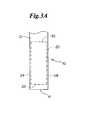
- FIG. 3Ais a top plan view of an embodiment of an inventive medical device having a rotational marker at a first rotational orientation.
- FIG. 3Bis an end view of an embodiment of an inventive medical device having a rotational marker at a first rotational orientation.
- FIG. 3Cis a top plan view of an embodiment of an inventive medical device having a rotational marker at a second rotational orientation.
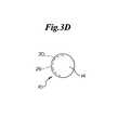
- FIG. 3Dis an end view of an embodiment of an inventive medical device having a rotational marker at a second rotational orientation.
- FIG. 3Eis a top plan view of an embodiment of an inventive medical device having a rotational marker at a third rotational orientation.
- FIG. 3Fis an end view of an embodiment of an inventive medical device having a rotational marker at a third rotational orientation.
- FIG. 3Gis a top plan view of an embodiment of an inventive medical device having a rotational marker at a fourth rotational orientation.
- FIG. 3His an end view of an embodiment of an inventive medical device having a rotational marker at a fourth rotational orientation.
- FIG. 4is a perspective view of another embodiment of an inventive medical device having a rotational marker.
- FIG. 5is a view of an embodiment of an inventive medical device having a rotational marker positioned within a bodily lumen.
- FIG. 6is a perspective view of another embodiment of an inventive medical device having a rotational marker.
- FIG. 7is a perspective view of an inventive medical device having further embodiments of rotational markers.
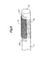
- FIG. 8is a perspective view of another embodiment of an inventive medical device having a rotational marker.
- FIG. 9is a perspective view of another embodiment of an inventive medical device having a rotational marker.
- FIG. 10is a plan view of the medical device according to FIG. 9 .
- FIG. 11is a perspective view of an embodiment of an inventive medical device having a rotational marker system.
- FIG. 12is a perspective view of another embodiment of an inventive medical device having a rotational marker system.
- FIG. 13is a perspective view of another embodiment of an inventive medical device having a rotational marker system.
- FIG. 14is a view of an embodiment of an inventive medical device having a rotational marker positioned within a bodily lumen.
- FIG. 15is a perspective view of another embodiment of an inventive medical device having a rotational marker system.
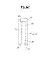
- FIG. 16is a perspective view of another embodiment of an inventive medical device having a rotational marker system.
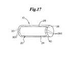
- FIG. 17is a perspective view of another embodiment of an inventive medical device having a rotational marker system.
- FIG. 18is a perspective view of another embodiment of an inventive medical device having a rotational marker system.
- FIG. 19is a perspective view of another embodiment of an inventive medical device having a rotational marker system.
- FIG. 20is a perspective view of another embodiment of an inventive medical device having a rotational marker system disposed within a bodily lumen.
- the present inventive deviceallows for proper rotational orientation of an implantable medical device, such as a stent, stent-graft, vena cava filter, distal protection device, or the like.
- the inventive devicemay also allow for proper rotational orientation of a delivery device, such as a catheter.
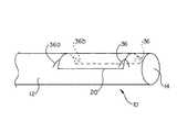
- FIG. 1shows a medical device 10 having a rotational marker 20 .
- the rotational marker 20is arranged to allow for a determination of the rotational orientation of the medical device 10 with respect to the surrounding environment.
- a rotational marker 20may be mounted to the surface of a medical device 10 or may be partially or fully recessed beneath the surface.
- the rotational marker 20is desirably viewable after insertion into a bodily lumen through an imaging device such as a fluoroscope or an MRI system.
- Markers 20may comprise radiopaque markers.
- Markers 20may comprise MRI markers.
- Radiopaque markers 20may be any suitable radiopaque material, such as barium, bismuth, tungsten, gold, titanium, iridium, platinum, palladium, silver, rhenium, tantalum, niobium, molybdenum, rhodium, palladium, hafnium, iridium or alloys or composites of these materials, and others, such as disclosed in U.S. Pat. No. 6,315,790, incorporated herein by reference.
- suitable radiopaque materialsuch as barium, bismuth, tungsten, gold, titanium, iridium, platinum, palladium, silver, rhenium, tantalum, niobium, molybdenum, rhodium, palladium, hafnium, iridium or alloys or composites of these materials, and others, such as disclosed in U.S. Pat. No. 6,315,790, incorporated herein by reference.
- MRI markers 20may be any suitable material, and desirably a ferro-magnetic, superparamagnetic or paramagnetic material, such as gadolinium, iron or manganese containing alloys, or gadolinium-DTPA (diethylene triamine pentaacetic acid) chelates as disclosed in U.S. Pat. No. 6,361,759, incorporated herein by reference.
- a ferro-magnetic, superparamagnetic or paramagnetic materialsuch as gadolinium, iron or manganese containing alloys, or gadolinium-DTPA (diethylene triamine pentaacetic acid) chelates as disclosed in U.S. Pat. No. 6,361,759, incorporated herein by reference.
- Markers 20may comprise a single composition of material. Markers 20 may also have a plurality of sections or portions of differing materials. Various materials may be more or less visible when viewed through an imaging device. Thus, certain portions of a rotational marker 20 may be more or less visible than other portions of the marker 20 .
- Rotational markers 20may be attached to the medical device 10 using any suitable method.
- markers 20may be bonded to the device 10 with an adhesive.
- Markers 20may be attached to the device 10 using RF energy, IR energy, UV energy, laser energy, ultra-sonic energy, electrical energy, and any combination thereof.
- the application of energymay physically bond the material of the marker 20 with the material of the device 10 .
- the application of energymay melt only the material of the device 10 , allowing the material of the device 10 to surround the marker 20 .
- Markers 20may also be inserted into the device 10 as the device is being formed, such as during extrusion or molding of the device 10 .
- the medical device 10may comprise a catheter shaft 12 having a distal end 14 and a proximal end 16 .
- an implantable medical devicemay be disposed about the catheter shaft 12 for delivery into a bodily lumen.
- a catheter 12may be made from any suitable material, such as polyesters and copolymers thereof such as those sold including polyalkylene terephthalates such as polyethylene terephthalate (PET) and polybutylene terephthalate (PBT) available under the tradename of EKTAR® available from Eastman Chemical Co.
- PETpolyethylene terephthalate
- PBTpolybutylene terephthalate
- PCTpolycyclohexylene terephthalate
- PTTpoly(trimethylene terephthalate)
- PCTGpoly(cyclohexanedimethanol-co-ethylene terephthalate)
- PENpoly(ethylene naphthalate) polyester available from DuPont in Wilmington, Del.
- polyester elastomersPETs
- polyamidessuch as amorphous nylon and nylon 12 such as those available from Elf Atochem under the tradename of CRISTAMID® and copolymers thereof such as GRILAMID® TR-55-LX nylon 12 polyether-block-amide available from EMS-American Grilon in Sumter, S.C.
- polyetherimidesavailable from GE Plastics under the tradename of ULTEM®
- a rotational marker 20may comprise a wire.
- a wire marker 20may be a generally elongate element having any desired shape and may contain portions having a straight, arcuate, sinuous or serpentine longitudinal axis. Further, a wire marker 20 may have any cross-sectional shape.
- a wire marker 20may comprise a first portion 24 extending along a portion of the length of the medical device 10 , and a second portion 26 extending about a radial arc or circumferential portion of the medical device 10 .
- the marker 20may further include a third portion 28 extending along a portion of the length of the medical device 10 , and a fourth portion 30 extending about a radial arc or circumferential portion of the medical device 10 .
- the first portion 24 and the third portion 28may comprise generally lengthwise portions and may be parallel to one another and have the same length. In some embodiments, first portion 24 and the third portion 28 may be parallel to the longitudinal axis of the medical device 10 .
- the second portion 26 and the fourth portion 30may comprise generally arcuate portions, may be parallel to one another and may have the same arcuate length.
- a wire marker 20may comprise only a lengthwise portion 24 .
- a wire marker 20may comprise only an arcuate portion 26 .
- Arcuate portions 26 , 30may also be characterized as extending in a circumferential direction about the longitudinal axis of the medical device 10 .
- a portion that extends in a circumferential direction about the longitudinal axis of the medical device 10may be contained within a plane perpendicular to the longitudinal axis of the medical device 10 . However, such a portion is not required to be located a constant radial distance from the longitudinal axis of the medical device 10 .
- radial distance from the longitudinal axis of the medical device 10 as the arcuate portion 26 , 30 is traversedmay be variable.
- a rotational marker 20 comprising a wiremay be continuous along its length. Further, the wire marker 20 may include a closed circuit, wherein each section 24 , 26 , 28 , 30 is coupled at one end to an adjacent section 24 , 26 , 28 , 30 and at the other end to another adjacent section 24 , 26 , 28 , 30 .
- FIG. 2shows a medical device 10 comprising a catheter 12 having a rotational marker 20 , and an implantable medical device 40 , such as a stent or stent-graft, mounted upon the catheter 12 .
- a stent 40may include a graft portion 42 or other covering over a portion of the stent 40 .
- Suitable coveringsinclude nylon, collagen, PTFE and expanded PTFE, polyethylene terephthalate and KEVLAR, or any of the materials disclosed in U.S. Pat. Nos. 5,824,046 and 5,755,770.
- any known graft materialmay be used including synthetic polymers such as polyethylene, polypropylene, polyurethane, polyglycolic acid, polyesters, polyamides, their mixtures, blends and copolymers.
- the graft portion 42is located in relation to the rotational marker 20 such that the rotational marker 20 can be used to correctly position the graft 42 within a bodily lumen.
- the size and location of rotational markers 20 on a medical device 10may be adjusted as suitable for the particular application.
- lengthwise portions 24 , 28 of the marker 20may be substantially coextensive with an implantable medical device 40 , or may extend slightly beyond the ends of an implantable medical device 40 .
- lengthwise portions 24 , 28may be placed near the edges of a graft portion 42 .
- Arcuate portions 26 , 30may have an arc length similar to the arc length of a graft portion 42 .
- the arcuate portions 26 , 30may have an arc length of 180°.
- Lengthwise portions 24 , 28may be of any suitable length.
- the length of a lengthwise portion 24 , 28could range from 0.1 millimeter to over 1 meter. Desirably, the length of a lengthwise portion 24 , 28 will range from 5 millimeters to 130 millimeters.
- Arcuate portions 26 , 30may also be of any suitable arc length, such as ranging from 0.1° to a full 360°. Desirably, arcuate portions 26 , 30 have an arc length ranging from 90° to 180°.
- length of a rotational marker 20may be longer or shorter than the length of an implantable medical device 40 .
- the arc length of appropriate portions of a rotational marker 20may be more or less than the arc length of a graft portion 42 .
- the lengthwise midpoint of a stent 40may be positioned near the midpoint of a lengthwise portion 24 , 28 of a rotational marker 20 .
- the midpoint of arcuate portions 26 , 30 of a rotational marker 20may be positioned near the midpoint of a graft portion 42 about the circumference of the stent 40 .
- FIGS. 3A , 3 C, 3 E and 3 Gdepict top plan views of a medical device 10 having a rotational marker 20 .
- FIGS. 3B , 3 D, 3 F and 3 Hdepict end views of a medical device 10 having a rotational marker 20 .
- FIGS. 3C and 3Ddepict the medical device 10 in a position rotated 90° from the position depicted in FIGS. 3A and 3B , respectively. As shown in FIG. 3C , when a first portion 24 of a rotational marker 20 is directly beneath a third portion 28 , the portions will appear as a single line in plan view.
- FIGS. 3E-3Hdepict the medical device 10 in rotational positions intermediate to the positions shown in FIGS. 3A and 3B and FIGS.
- FIGS. 3A-3Hshow how the rotational orientation of a medical device 10 may be determined by viewing a rotational marker 20 through an imaging device after the medical device 10 has been inserted into a bodily lumen.
- a graft portion 42 of an implantable medical device 40is arranged in relation to the rotational marker 20 , exact placement of the graft portion 42 within a bodily lumen is facilitated.
- FIG. 4shows a medical device 10 comprising a catheter shaft 12 and a catheter outer wall or sheath 50 .
- An implantable medical device 40 having a graft portion 42is mounted upon a catheter shaft 12 beneath the sheath 50 .
- the implantable medical device 40may comprise a self-expanding stent.
- the sheath 50may constrain the implantable medical device 40 .
- the implantable medical device 40is allowed to expand.
- a lubricious coating between the sheath 50 and the implantable medical device 40may be desirable.
- the sheath 50may include a rotational marker 20 .
- the sheath 50is positioned such that the rotational marker 20 overlays the graft portion 42 or otherwise indicates the rotational location of the graft portion.
- the rotational marker 20may also indicate the approximate length of the implantable medical device 40 .
- a sheath 50includes a rotational marker 20
- An axial couplingdesirably prevents rotation between the components that are axially coupled to one another.
- a rotational marker 20may be rotationally fixed in place above a graft portion 42 , and will remain directly above the graft 42 until the sheath 50 is displaced axially, such as by retraction.
- FIG. 5depicts an implantable medical device 40 being delivered for placement within a bodily lumen 60 having a sidebranch 62 and an aneurysm 64 .
- the medical device 10comprises a catheter shaft 12 , a sheath 50 and a rotational marker 20 .
- An implantable medical device 40 having a graft portion 42is arranged between the catheter shaft 12 and the sheath 50 .
- the rotational marker 20is positioned to indicate the approximate location and rotational orientation of the graft portion 42 .
- the rotational marker 20facilitates placement of the implantable medical device 40 such that the graft portion 42 can cover the aneurysm 64 without a consequential blockage of the sidebranch 62 .
- a rotational marker 20 comprising a wiremay traverse a generally sinuous or serpentine path, as shown in FIG. 6 .
- a serpentine wire marker 20may include sections that are generally lengthwise 24 , 28 and sections that are generally circumferential 26 , 30 . Generally lengthwise sections 24 , 28 may be substantially parallel to the longitudinal axis of the device 10 .
- a serpentine wire marker 20may further include intermediate sections 32 that are neither circumferential nor parallel to the longitudinal axis of the device 10 .
- serpentine wire marker 20may be arranged to generally indicate the edges of a graft portion 42 of an implantable medical device 40 .
- a serpentine wire marker 20will desirably indicate the rotational position of a graft portion 42 under fluoroscopy or MRI.
- FIG. 7depicts additional embodiments of rotational markers 20 .
- a marker 20may comprise a generally circumferential length of wire 26 a , which may have any span desired.
- a markermay further comprise at first lengthwise portion 24 a and a second lengthwise portion 28 a .
- a marker 20may comprise a generally serpentine closed loop 20 a spanning a substantially shorter length of the medical device 10 than the length of an eventual implantable medical device 40 .
- An inventive medical device 10may include a plurality of rotational markers 20 .
- the markers 20may be placed to collectively indicate the position of an eventual implantable medical device 40 or graft portion 42 .
- a first rotational marker 20 bmay be mounted near a proximal end of a graft portion 42
- a second rotational marker 20 cmay be mounted near a distal end of a graft portion 42 .
- rotational markers 20may comprise proximal markers 20 b and distal markers 20 c.
- FIGS. 9 and 10show further embodiments of a medical device 10 having a rotational marker 20 .
- a rotational marker 20may further comprise directional indicators 36 .
- Directional indicators 36may be positioned to further indicate the position of an implantable medical device 40 or graft portion 42 when the marker 20 is viewed through an imaging system.
- Directional indicators 36may be made from the same materials as the rest of the marker 20 , or may comprise a different material to result in greater or lesser visibility than other portions of the marker 20 when viewed through an imaging system.
- directional indicators 36 of a rotational marker 20may appear as two-dimensional symbols in plan view, such as arrows.
- the directional indicators 36may be positioned to indicate the direction of a graft portion 42 .
- Directional indicators 36may be arranged to form a recognizable symbol upon an imaging device throughout only a predetermined rotational range, such as 10° to 30°.
- a directional indicator 36may comprise only a portion of a symbol that will be viewable through an imaging device.
- a directional indicator 36 and another part of the marker 20can form a symbol.
- two separate directional indicators 36 a , 36 bcan form a symbol.
- FIG. 9shows a first directional indicator 36 a and a second directional indicator 36 b .
- the first and second indicators 36 a , 36 bmay combine to depict a complete arrow over a narrow range of rotation of the medical device 10 , such as 10° or less in some embodiments, and 5° or less in some embodiments.
- a plurality of individual markers 22may collectively comprise a rotational marker 20 or a rotational marker 20 system.
- Individual markers 22may be attached to the device 10 using any suitable method.
- Individual markers 22may follow any suitable pattern, and may form a straight, arcuate, sinuous or serpentine path.
- Individual markers 22may be positioned to form a symbol when viewed upon an imaging device at a correct rotational orientation.
- FIGS. 12 and 13depict further embodiments of a medical device 10 having a rotational marker system comprising a first individual marker 22 a and a second individual marker 22 b .
- the first individual marker 22 awill appear to have a greater luminosity than the second individual marker 22 b when viewed upon an imaging device.
- the first individual marker 22 amay be more visible than the second individual marker 22 b .
- the first individual marker 22 acomprises a different material than the second individual marker 22 b .
- the first individual marker 22 bmay comprise the same material as the second individual marker 22 a but have a greater mass.
- an inventive medical device 10may include a first individual marker 22 a and a second individual marker 22 b , each individual marker 22 a , 22 b having an enhanced radiopacity when compared to other portions of the device 10 .
- the first individual marker 22 amay have a higher degree of radiopacity than the second individual marker 22 b.
- FIG. 13shows a medical device 10 comprising a catheter having a catheter shaft 12 and a sheath 50 .
- An implantable medical device 40 having a graft portion 42is mounted upon the catheter shaft 12 .
- the catheter shaft 12may include a first individual marker 22 a and a second individual marker 22 b .
- the sheath 50may include a first individual marker 22 a and a second individual marker 22 b.
- a first individual marker 22 a and a second individual marker 22 bmay be placed anywhere upon the medical device 10 to allow an operator to determine the rotational orientation of the device 10 .
- the individual markers 22 a , 22 bmay comprise lengthwise strips or wires.
- the length and placement of markers 22 comprising stripsmay be chosen to represent the bounds of an implantable medical device 40 .
- the length of a strip marker 22may be equal to the length of a stent 40 .
- a first individual marker 22 a and a second individual marker 22 bmay be placed near the opposing longitudinal ends of a graft portion 42 of a stent 40 .
- the bounds of the graft 42may be visualized upon an imaging device.
- a first individual marker 22 amay be placed to correspond to the midpoint of a graft portion 42 about the circumference of the implantable medical device 40 .
- a second individual marker 22 bmay be placed to correspond to the middle of the ungrafted portion of a stent 40 .
- the first individual marker 22 amay be 180° away from the second individual marker 22 b , or placed directly across the implantable medical device 40 .
- FIG. 14depicts an image of a rotational marker 20 system comprising a first individual marker 22 a and a second individual marker 22 b as viewed upon an imaging device within a bodily lumen 60 .
- the first individual marker 22 adesirably appears brighter, more intense or more visible than the second individual marker 22 b , and may be used to determine the rotational orientation of a graft portion 42 for proper placement over an aneurysm 64 .
- an inventive medical device 10may comprise an implantable medical device 40 having a rotational marker 20 .
- a rotational marker 20is included on an implantable medical device 40 , rotational markers are not required on a delivery system.
- Rotational markers 20may be attached to an implantable medical device 40 using any suitable method, such as by adhesive or by the application RF energy, IR energy, UV energy, laser energy, ultra-sonic energy, electrical energy, and any combination thereof.
- markers 20may be contained within a graft portion 42 , such as being sandwiched between layers of a graft 42 and methods disclosed in U.S. patent application Ser. No. 10/600,022, incorporated herein by reference.
- FIG. 15shows a medical device 10 comprising an implantable medical device 40 having a first individual marker 22 a and a second individual marker 22 b .
- the individual markers 22 a , 22 bare shown near the edges of a graft portion 42 .
- a first individual marker 22 amay be placed to correspond to the midpoint of a graft portion 42 about the circumference of the implantable medical device 40 .
- a second individual marker 22 bmay be placed to correspond to the middle of the ungrafted portion of a stent 40 .
- the first individual marker 22 amay be 180° away from the second individual marker 22 b , or placed directly across the implantable medical device 40 .
- FIG. 16shows a medical device 10 comprising an implantable medical device 40 having a plurality of first individual markers 22 a and a plurality of second individual markers 22 b .
- Individual markers 22 a , 22 b in this embodimentdo not span the entire length of the implantable medical device 40 .
- Shorter markers 22 a , 22 ballow for a shift in positioning of the markers as may be required during expansion of the implantable medical device 40 .
- FIGS. 17 and 18show a medical device 10 comprising an implantable medical device 40 having a rotational marker 20 .
- the rotational markermay comprise a first portion 24 extending along the length of the medical device 10 , and a second portion 26 extending about a radial arc or circumferential portion of the implantable medical device 40 .
- the marker 20may further include a third portion 28 extending along the length of the medical device 10 , and a fourth portion 30 extending about a radial arc or circumferential portion of the implantable medical device 40 .
- the arcuate portions 26 , 30 of a rotational marker 20may comprise a plurality of arcuate elements 26 a , 30 a .
- Arcuate elements 26 a , 30 amay be arranged in a generally linear, single file path, or may have overlapping portions as shown in FIG. 18 . Overlapping portions may allow the arcuate sections 26 , 30 to be more visible when viewed through an imaging device. Further, as an implantable medical device 40 expands, arcuate elements 26 a , 30 a may displace with respect to one another as the diameter of the implantable medical device 40 grows. Thus, an arcuate section 26 , 30 comprising arcuate elements 26 a , 30 a will allow for expansion of an implantable medical device 40 .
- a medical device 10may comprise a balloon catheter having a rotational marker 20 , as shown in FIG. 19 .
- a rotational marker 20may be attached directly to an expansion balloon 48 using any of the methods disclosed herein.
- a balloon 48may have a rotational marker 20 comprising a first individual marker 22 a and a second individual marker 22 b .
- the first individual marker 22 awill appear to have a greater luminosity than the second individual marker 22 b when viewed upon an imaging device.
- a balloon 48may have a rotational marker 20 comprising a first portion 24 extending along the length of the balloon 48 , and a second portion 26 extending about a radial arc or circumferential portion of the balloon 48 .
- the marker 20may further include a third portion 28 extending along the length of the balloon 48 , and a fourth portion 30 extending about a radial arc or circumferential portion of the balloon 48 .
- Lengthwise sections 24 , 28may comprise a plurality of portions or elements.
- arcuate sections 26 , 30may comprise a plurality of arcuate elements 26 a , 30 a.
- a medical device 10may include a rotational marker 20 , or a rotational marker system.
- the devicemay comprise a circumferential wall having a lumen 52 extending therethrough.
- a wall of the medical device 10may further include an aperture or port 68 .
- the port 68may be positioned such that orientation and placement of the port 68 may be determined via the image of a rotational marker 20 upon an imaging device. It is also within the scope of the invention for port 68 to be provided with a radiopaque marker on the rim of the port.
- the radiopaque markermay be of any suitable type including, but not limited to a coating.
- the medical device 10may further include a rotational ablation device 70 , and the medical device 10 may be used to remove plaque and other deposits 72 from a vessel wall as disclosed in U.S. Pat. No. 6,179,851, the entire disclosure of which is incorporated herein by reference.
- the inventionis also directed to a method of using an inventive medical device in an atherectomy procedure.
- the medical device 10may be inserted into a bodily lumen 60 and maneuvered to a vessel location having a deposit 72 , such as plaque, a clot or another type of thrombus.
- An imaging devicemay be used to view a rotational marker 20 to facilitate positioning the device 10 with the port 68 immediately adjacent to a deposit 72 .
- rotational ablation device 70may remove portions of the deposit 72 from the vessel wall. The portions that have been removed may then enter the port 68 .
- the removed deposit 72 materialmay be carried away within a lumen 52 of the medical device 10 .
- rotational ablation devicesmay be incorporated into or used in conjunction with an inventive medical device 10 , such as disclosed in U.S. Pat. Nos. 6,596,005, 6,503,261 and 6,270,509, the entire disclosures of which are incorporated herein by reference.
- rotational markers and/or rotational marker systemsmay be used with a rotational ablation device or a medical device that includes or may work in conjunction with a rotational ablation device.
- a method of using an embodiment of the inventive medical device 10 for properly positioning a graft portion 42generally comprises delivering the medical device 10 to a deployment location within a bodily lumen 60 , as shown in FIGS. 5 and 14 .
- the medical device 10may comprise a catheter 12 or introducer.
- the medical device 10may comprise an implantable medical device 40 , and may be delivered to the deployment site with an introducer, such as a prior art catheter or an inventive catheter 12 .
- the deployment location and the marker 20may be viewed upon an imaging device.
- the rotational orientation of the medical device 10may be determined by the image of the rotational marker 20 appearing upon the imaging device. If the marker 20 includes portions that indicate the length of an implantable medical device 40 , the axial location of the implantable medical device 40 may also be determined in relative to the deployment site.
- Rotation of the proximal end of the introducerwill cause a rotation of the medical device 10 and of the rotational marker 20 and graft portion 42 .
- the rotational marker 20 and graft portion 42may then be properly positioned rotationally with respect to an aneurysm 64 .
- Deployment of an implantable medical device 40may be accomplished by any known method, such as by expansion balloon 48 or by retraction of a sheath 50 and self-expansion of the implantable medical device 40 .
- any of the inventive medical devices 10 disclosed hereinmay be provided with a uniform diameter or may taper in portions or along the entire length of the device. Further, the width and/or thickness of the various portions of a device may increase or decrease along a given portion of the device.
- the inventive devices 10may also be provided with various bio-compatible coatings.
- the inventive devicesmay be provided with lubricious coatings.
- the inventive devicesmay also be provided with drug-containing coatings which release drugs over time.
- the inventive devicesmay also be provided with a sugar or more generally a carbohydrate and/or a gelatin to maintain a stent on a catheter or balloon during delivery of the stent to a desired bodily location.
- a coatingmay comprise one or more non-genetic therapeutic agents, genetic materials and cells and combinations thereof as well as other polymeric coatings.
- Non-genetic therapeutic agentsinclude anti-thrombogenic agents such as heparin, heparin derivatives, urokinase, and PPack (dextrophenylalanine proline arginine chloromethylketone); anti-proliferative agents such as enoxaprin, angiopeptin, or monoclonal antibodies capable of blocking smooth muscle cell proliferation, hirudin, and acetylsalicylic acid; anti-inflammatory agents such as dexamethasone, prednisolone, corticosterone, budesonide, estrogen, sulfasalazine, and mesalamine; antineoplastic/antiproliferative/anti-miotic agents such as paclitaxel, 5-fluorouracil, cisplatin, vinblastine, vincristine, epothilones, endostatin, angiostatin and thymidine kinase inhibitors; anesthetic agents such as lidocaine, b
- Genetic materialsinclude anti-sense DNA and RNA, DNA coding for, anti-sense RNA, tRNA or rRNA to replace defective or deficient endogenous molecules, angiogenic factors including growth factors such as acidic and basic fibroblast growth factors, vascular endothelial growth factor, epidermal growth factor, transforming growth factor ⁇ and ⁇ , platelet-derived endothelial growth factor, platelet-derived growth factor, tumor necrosis factor ⁇ , hepatocyte growth factor and insulin like growth factor, cell cycle inhibitors including CD inhibitors, thymidine kinase (“TK”) and other agents useful for interfering with cell proliferation the family of bone morphogenic proteins (“BMP′′s”), BMP-2, BMP-3, BMP-4, BMP-5, BMP-6 (Vgr-1), BMP-7 (OP-1), BMP-8, BMP-9, BMP-10, BMP-11, BMP-12, BMP-13, BMP-14, BMP-15, and BMP-16.
- growth factorssuch as acidic and basic
- Desirable BMP′′sare any of BMP-2, BMP-3, BMP-4, BMP-5, BMP-6 and BMP-7. These dimeric proteins can be provided as homodimers, heterodimers, or combinations thereof, alone or together with other molecules. Alternatively or, in addition, molecules capable of inducing an upstream or downstream effect of a BMP can be provided. Such molecules include any of the “hedgehog” proteins, or the DNA′′s encoding them.
- Suitable polymer coating materialsinclude polycarboxylic acids, cellulosic polymers, including cellulose acetate and cellulose nitrate, gelatin, polyvinylpyrrolidone, cross-linked polyvinylpyrrolidone, polyanhydrides including maleic anhydride polymers, polyamides, polyvinyl alcohols, copolymers of vinyl monomers such as EVA, polyvinyl ethers, polyvinyl aromatics, polyethylene oxides, glycosaminoglycans, polysaccharides, polyesters including polyethylene terephthalate, polyacrylamides, polyethers, polyether sulfone, polycarbonate, polyalkylenes including polypropylene, polyethylene and high molecular weight polyethylene, halogenated polyalkylenes including polytetrafluoroethylene, polyurethanes, polyorthoesters, proteins, polypeptides, silicones, siloxane polymers, polylactic acid, polyglycolic acid, polycaprolactone
- Polyacrylic acidavailable as HYDROPLUS® (Boston Scientific Corporation, Natick, Mass.), and described in U.S. Pat. No. 5,091,205, the disclosure of which is hereby incorporated herein by reference, is particularly desirable. Even more desirable is a copolymer of polylactic acid and polycaprolactone.
- the inventive devicesmay find use in coronary arteries, renal arteries, peripheral arteries including iliac arteries, arteries of the neck and cerebral arteries, as well as other body structures, including but not limited to arteries, veins, biliary ducts, urethras, fallopian tubes, bronchial tubes, the trachea, the esophagus, the prostate and the bowels.
- any dependent claim which followsshould be taken as alternatively written in a multiple dependent form from all prior claims which possess all antecedents referenced in such dependent claim if such multiple dependent format is an accepted format within the jurisdiction (e.g. each claim depending directly from claim 1 should be alternatively taken as depending from all previous claims).
- each claim depending directly from claim 1should be alternatively taken as depending from all previous claims.
- the following dependent claimsshould each be also taken as alternatively written in each singly dependent claim format which creates a dependency from a prior antecedent-possessing claim other than the specific claim listed in such dependent claim below.
Landscapes
- Health & Medical Sciences (AREA)
- Life Sciences & Earth Sciences (AREA)
- Veterinary Medicine (AREA)
- Pulmonology (AREA)
- Public Health (AREA)
- General Health & Medical Sciences (AREA)
- Engineering & Computer Science (AREA)
- Biomedical Technology (AREA)
- Heart & Thoracic Surgery (AREA)
- Animal Behavior & Ethology (AREA)
- Transplantation (AREA)
- Vascular Medicine (AREA)
- Oral & Maxillofacial Surgery (AREA)
- Cardiology (AREA)
- Gastroenterology & Hepatology (AREA)
- Biophysics (AREA)
- Anesthesiology (AREA)
- Hematology (AREA)
- Prostheses (AREA)
- Media Introduction/Drainage Providing Device (AREA)
Abstract
Description
Claims (24)
Priority Applications (2)
| Application Number | Priority Date | Filing Date | Title |
|---|---|---|---|
| US10/719,421US8014849B2 (en) | 2003-11-21 | 2003-11-21 | Rotational markers |
| PCT/US2004/030670WO2005055880A1 (en) | 2003-11-21 | 2004-09-20 | Rotational markers |
Applications Claiming Priority (1)
| Application Number | Priority Date | Filing Date | Title |
|---|---|---|---|
| US10/719,421US8014849B2 (en) | 2003-11-21 | 2003-11-21 | Rotational markers |
Publications (2)
| Publication Number | Publication Date |
|---|---|
| US20050113686A1 US20050113686A1 (en) | 2005-05-26 |
| US8014849B2true US8014849B2 (en) | 2011-09-06 |
Family
ID=34591318
Family Applications (1)
| Application Number | Title | Priority Date | Filing Date |
|---|---|---|---|
| US10/719,421Expired - Fee RelatedUS8014849B2 (en) | 2003-11-21 | 2003-11-21 | Rotational markers |
Country Status (2)
| Country | Link |
|---|---|
| US (1) | US8014849B2 (en) |
| WO (1) | WO2005055880A1 (en) |
Cited By (43)
| Publication number | Priority date | Publication date | Assignee | Title |
|---|---|---|---|---|
| US20080125626A1 (en)* | 2004-04-21 | 2008-05-29 | Acclarent, Inc. | Devices, Systems and Methods Useable for Treating Sinusitis |
| US20110112398A1 (en)* | 2009-11-08 | 2011-05-12 | Paieon Inc. | Apparatus and method for locating a device tip within a volume |
| US8702626B1 (en) | 2004-04-21 | 2014-04-22 | Acclarent, Inc. | Guidewires for performing image guided procedures |
| US8764729B2 (en) | 2004-04-21 | 2014-07-01 | Acclarent, Inc. | Frontal sinus spacer |
| US8764786B2 (en) | 2002-09-30 | 2014-07-01 | Acclarent, Inc. | Balloon catheters and methods for treating paranasal sinuses |
| US8764709B2 (en) | 2004-04-21 | 2014-07-01 | Acclarent, Inc. | Devices, systems and methods for treating disorders of the ear, nose and throat |
| US8777926B2 (en) | 2004-04-21 | 2014-07-15 | Acclarent, Inc. | Apparatus and methods for dilating and modifying ostia of paranasal sinuses and other intranasel or paranasal structures |
| US8864787B2 (en) | 2004-04-21 | 2014-10-21 | Acclarent, Inc. | Ethmoidotomy system and implantable spacer devices having therapeutic substance delivery capability for treatment of paranasal sinusitis |
| US8894614B2 (en) | 2004-04-21 | 2014-11-25 | Acclarent, Inc. | Devices, systems and methods useable for treating frontal sinusitis |
| US8905922B2 (en) | 2004-04-21 | 2014-12-09 | Acclarent, Inc. | Devices, systems and methods for diagnosing and treating sinusitis and other disorders of the ears, nose and/or throat |
| US8932276B1 (en) | 2004-04-21 | 2015-01-13 | Acclarent, Inc. | Shapeable guide catheters and related methods |
| US8951225B2 (en) | 2005-06-10 | 2015-02-10 | Acclarent, Inc. | Catheters with non-removable guide members useable for treatment of sinusitis |
| US8961398B2 (en) | 2004-04-21 | 2015-02-24 | Acclarent, Inc. | Methods and apparatus for treating disorders of the ear, nose and throat |
| US8968269B2 (en) | 2005-09-23 | 2015-03-03 | Acclarent, Inc. | Multi-conduit balloon catheter |
| US9072626B2 (en) | 2009-03-31 | 2015-07-07 | Acclarent, Inc. | System and method for treatment of non-ventilating middle ear by providing a gas pathway through the nasopharynx |
| US9089258B2 (en) | 2004-04-21 | 2015-07-28 | Acclarent, Inc. | Endoscopic methods and devices for transnasal procedures |
| US9101384B2 (en) | 2004-04-21 | 2015-08-11 | Acclarent, Inc. | Devices, systems and methods for diagnosing and treating sinusitis and other disorders of the ears, Nose and/or throat |
| US9308361B2 (en) | 2005-01-18 | 2016-04-12 | Acclarent, Inc. | Implantable devices and methods for treating sinusitis and other disorders |
| US9351750B2 (en) | 2004-04-21 | 2016-05-31 | Acclarent, Inc. | Devices and methods for treating maxillary sinus disease |
| US9399121B2 (en) | 2004-04-21 | 2016-07-26 | Acclarent, Inc. | Systems and methods for transnasal dilation of passageways in the ear, nose or throat |
| US9439793B2 (en) | 2013-03-12 | 2016-09-13 | Cook Medical Technologies Llc | Extension for iliac branch delivery device and methods of using the same |
| US9463068B2 (en) | 2007-05-08 | 2016-10-11 | Acclarent, Inc. | Methods and devices for protecting nasal turbinates |
| US9468362B2 (en) | 2004-04-21 | 2016-10-18 | Acclarent, Inc. | Endoscopic methods and devices for transnasal procedures |
| US9522073B2 (en) | 2012-02-08 | 2016-12-20 | Cook Medical Technologies Llc | Orientation markers for endovascular delivery system |
| US9572480B2 (en) | 2006-09-15 | 2017-02-21 | Acclarent, Inc. | Methods and devices for facilitating visualization in a surgical environment |
| US9629684B2 (en) | 2013-03-15 | 2017-04-25 | Acclarent, Inc. | Apparatus and method for treatment of ethmoid sinusitis |
| US9636258B2 (en) | 2009-03-31 | 2017-05-02 | Acclarent, Inc. | System and method for treatment of non-ventilating middle ear by providing a gas pathway through the nasopharynx |
| US9750401B2 (en) | 2008-07-30 | 2017-09-05 | Acclarent, Inc. | Paranasal ostium finder devices and methods |
| US9820688B2 (en) | 2006-09-15 | 2017-11-21 | Acclarent, Inc. | Sinus illumination lightwire device |
| US9826999B2 (en) | 2004-04-21 | 2017-11-28 | Acclarent, Inc. | Methods and apparatus for treating disorders of the ear nose and throat |
| US9861793B2 (en) | 2008-03-10 | 2018-01-09 | Acclarent, Inc. | Corewire design and construction for medical devices |
| US10130501B2 (en) | 2013-03-12 | 2018-11-20 | Cook Medical Technologies Llc | Delivery device with an extension sheath and methods of using the same |
| US10188413B1 (en) | 2004-04-21 | 2019-01-29 | Acclarent, Inc. | Deflectable guide catheters and related methods |
| US10206821B2 (en) | 2007-12-20 | 2019-02-19 | Acclarent, Inc. | Eustachian tube dilation balloon with ventilation path |
| WO2019176533A1 (en)* | 2018-03-15 | 2019-09-19 | テルモ株式会社 | Medical device and identification method |
| US10524814B2 (en) | 2009-03-20 | 2020-01-07 | Acclarent, Inc. | Guide system with suction |
| US10856727B2 (en) | 2004-04-21 | 2020-12-08 | Acclarent, Inc. | Endoscopic methods and devices for transnasal procedures |
| US10874838B2 (en) | 2004-04-21 | 2020-12-29 | Acclarent, Inc. | Systems and methods for transnasal dilation of passageways in the ear, nose or throat |
| US11065061B2 (en) | 2004-04-21 | 2021-07-20 | Acclarent, Inc. | Systems and methods for performing image guided procedures within the ear, nose, throat and paranasal sinuses |
| US11426137B1 (en) | 2019-02-16 | 2022-08-30 | Innovative Ideas LLC | Medical imaging marker device comprising main marker piece and slidable marker piece, and method |
| US11529502B2 (en) | 2004-04-21 | 2022-12-20 | Acclarent, Inc. | Apparatus and methods for dilating and modifying ostia of paranasal sinuses and other intranasal or paranasal structures |
| US12167961B2 (en) | 2020-08-24 | 2024-12-17 | Edwards Lifesciences Corporation | Methods and systems for aligning a commissure of a prosthetic heart valve with a commissure of a native valve |
| US12290436B2 (en) | 2016-08-01 | 2025-05-06 | Edwards Lifesciences Corporation | Prosthetic heart valve |
Families Citing this family (46)
| Publication number | Priority date | Publication date | Assignee | Title |
|---|---|---|---|---|
| US7321677B2 (en)* | 2000-05-09 | 2008-01-22 | Paieon Inc. | System and method for three-dimensional reconstruction of an artery |
| ATE493070T1 (en)* | 2000-10-18 | 2011-01-15 | Paieon Inc | SYSTEM FOR POSITIONING A DEVICE IN A TUBULAR ORGAN |
| DE10105592A1 (en) | 2001-02-06 | 2002-08-08 | Achim Goepferich | Placeholder for drug release in the frontal sinus |
| US8126241B2 (en)* | 2001-10-15 | 2012-02-28 | Michael Zarkh | Method and apparatus for positioning a device in a tubular organ |
| WO2004075789A2 (en)* | 2003-02-26 | 2004-09-10 | Cook Incorporated | PROTHESIS ADAPTED FOR PLACEDd UNDER EXTERNAL IMAGING |
| EP1654704A2 (en)* | 2003-07-21 | 2006-05-10 | Paieon Inc. | Method and system for identifying an optimal image within a series of images that depict a moving organ |
| WO2005031635A1 (en)* | 2003-09-25 | 2005-04-07 | Paieon, Inc. | System and method for three-dimensional reconstruction of a tubular organ |
| DE102004008367A1 (en)* | 2004-02-20 | 2005-09-22 | Siemens Ag | Method for taking two-dimensional images inside a blood-perfused vessel by means of optical coherence tomography |
| US20060074285A1 (en)* | 2004-09-24 | 2006-04-06 | Paieon Inc. | Apparatus and method for fusion and in-operating-room presentation of volumetric data and 3-D angiographic data |
| US8295577B2 (en) | 2005-03-31 | 2012-10-23 | Michael Zarkh | Method and apparatus for guiding a device in a totally occluded or partly occluded tubular organ |
| IL169380A0 (en)* | 2005-06-23 | 2007-07-04 | Tsuriel Assis | Method and apparatus for determining the orientation of a device within a tubular lumen |
| US7632304B2 (en)* | 2005-09-07 | 2009-12-15 | Rbkpark Llc | Coronary stent |
| US9233012B2 (en) | 2005-09-07 | 2016-01-12 | RBKPark, LLC | Medical stent |
| DE102005059262B4 (en)* | 2005-12-12 | 2008-02-07 | Siemens Ag | catheter device |
| DE102006024245A1 (en)* | 2006-05-23 | 2007-08-02 | Siemens Ag | Medical instrument and method for localizing it in the human body |
| US8585594B2 (en) | 2006-05-24 | 2013-11-19 | Phoenix Biomedical, Inc. | Methods of assessing inner surfaces of body lumens or organs |
| US8439687B1 (en) | 2006-12-29 | 2013-05-14 | Acclarent, Inc. | Apparatus and method for simulated insertion and positioning of guidewares and other interventional devices |
| US8545548B2 (en) | 2007-03-30 | 2013-10-01 | DePuy Synthes Products, LLC | Radiopaque markers for implantable stents and methods for manufacturing the same |
| US20140094901A1 (en)* | 2007-03-30 | 2014-04-03 | DePuy Synthes Products, LLC | Radiopaque marker for vascular devices |
| US8118757B2 (en) | 2007-04-30 | 2012-02-21 | Acclarent, Inc. | Methods and devices for ostium measurement |
| US20090234267A1 (en)* | 2008-03-13 | 2009-09-17 | Ross John R | Method and device for easy access to vascular graft cannulation sites |
| US20100010339A1 (en)* | 2008-03-13 | 2010-01-14 | Smith Christopher K | Method and device for easy access to subintimally implanted vascular access ports |
| US8983577B2 (en)* | 2009-02-12 | 2015-03-17 | Koninklijke Philips N.V. | System for determining the orientation of a catheter |
| US8298187B2 (en)* | 2009-07-07 | 2012-10-30 | Cook Medical Technologies Llc | Fluid injection device |
| AU2015200049B2 (en)* | 2009-10-02 | 2016-11-10 | Medtronic Xomed, Inc. | Endotracheal tube apparatus |
| EP2482918B1 (en) | 2009-10-02 | 2016-06-29 | Medtronic Xomed, Inc. | Endotracheal tube apparatus |
| US8920486B2 (en) | 2010-05-18 | 2014-12-30 | RBKPark, LLC | Medical device |
| US9155492B2 (en) | 2010-09-24 | 2015-10-13 | Acclarent, Inc. | Sinus illumination lightwire device |
| US9585746B2 (en) | 2011-07-29 | 2017-03-07 | Carnegie Mellon University | Artificial valved conduits for cardiac reconstructive procedures and methods for their production |
| US9931079B2 (en) | 2012-01-04 | 2018-04-03 | Medtronic Xomed, Inc. | Clamp for securing a terminal end of a wire to a surface electrode |
| EP3281608B1 (en) | 2012-02-10 | 2020-09-16 | CVDevices, LLC | Medical product comprising a frame and visceral pleura |
| EP2633876B1 (en) | 2012-03-02 | 2014-09-24 | Cook Medical Technologies LLC | Dilation cap for endoluminal device |
| US20130289389A1 (en) | 2012-04-26 | 2013-10-31 | Focal Therapeutics | Surgical implant for marking soft tissue |
| US9060744B2 (en) | 2012-11-29 | 2015-06-23 | Medtronic Xomed, Inc. | Endobronchial tube apparatus |
| CA2900862C (en) | 2013-02-11 | 2017-10-03 | Cook Medical Technologies Llc | Expandable support frame and medical device |
| US9913594B2 (en) | 2013-03-14 | 2018-03-13 | Medtronic Xomed, Inc. | Compliant electrode for EMG endotracheal tube |
| US9254208B2 (en) | 2013-03-14 | 2016-02-09 | Thomas Ischinger | Oblique stent |
| US9433437B2 (en) | 2013-03-15 | 2016-09-06 | Acclarent, Inc. | Apparatus and method for treatment of ethmoid sinusitis |
| US10588642B2 (en) | 2014-05-15 | 2020-03-17 | Gauthier Biomedical, Inc. | Molding process and products formed thereby |
| CA2955956C (en)* | 2014-07-25 | 2022-10-18 | Focal Therapeutics, Inc. | Implantable devices and techniques for oncoplastic surgery |
| US9937333B2 (en) | 2015-09-01 | 2018-04-10 | Thomas Ischinger | Balloon catheter for treatment of a vessel at a bifurcation |
| WO2017151900A1 (en)* | 2016-03-02 | 2017-09-08 | Peca Labs, Inc. | Expandable implantable conduit |
| CN106730420A (en)* | 2017-02-06 | 2017-05-31 | 中国人民解放军总医院 | Tumor marker device |
| US11110240B2 (en) | 2017-09-07 | 2021-09-07 | Medtronic Xomed, Inc. | Endotracheal tube with tube coating |
| CA3128527A1 (en)* | 2020-09-10 | 2022-03-10 | Baylis Medical Company Inc. | Elongated medical catheter including marker band |
| US20230233316A1 (en)* | 2022-01-24 | 2023-07-27 | ACCO Health, Inc. | Heart valve using vascular graft |
Citations (44)
| Publication number | Priority date | Publication date | Assignee | Title |
|---|---|---|---|---|
| US4693237A (en)* | 1986-01-21 | 1987-09-15 | Hoffman Richard B | Radiopaque coded ring markers for use in identifying surgical grafts |
| US4718417A (en)* | 1985-03-22 | 1988-01-12 | Massachusetts Institute Of Technology | Visible fluorescence spectral diagnostic for laser angiosurgery |
| US5047050A (en) | 1987-02-17 | 1991-09-10 | Alberto Arpesani | Internal prosthesis with radiopaque annular portions |
| US5091205A (en) | 1989-01-17 | 1992-02-25 | Union Carbide Chemicals & Plastics Technology Corporation | Hydrophilic lubricious coatings |
| US5203777A (en)* | 1992-03-19 | 1993-04-20 | Lee Peter Y | Radiopaque marker system for a tubular device |
| US5425709A (en)* | 1993-07-22 | 1995-06-20 | C. R. Bard, Inc. | Sheath for a balloon catheter |
| US5489277A (en)* | 1991-05-17 | 1996-02-06 | Act Medical, Inc. | Device having a radiopaque marker for endoscopic accessories and method of making same |
| US5607442A (en) | 1995-11-13 | 1997-03-04 | Isostent, Inc. | Stent with improved radiopacity and appearance characteristics |
| US5681336A (en)* | 1995-09-07 | 1997-10-28 | Boston Scientific Corporation | Therapeutic device for treating vien graft lesions |
| US5741327A (en)* | 1997-05-06 | 1998-04-21 | Global Therapeutics, Inc. | Surgical stent featuring radiopaque markers |
| US5755770A (en) | 1995-01-31 | 1998-05-26 | Boston Scientific Corporatiion | Endovascular aortic graft |
| US5824042A (en)* | 1996-04-05 | 1998-10-20 | Medtronic, Inc. | Endoluminal prostheses having position indicating markers |
| US5824046A (en) | 1996-09-27 | 1998-10-20 | Scimed Life Systems, Inc. | Covered stent |
| US5921978A (en)* | 1997-06-20 | 1999-07-13 | Ep Technologies, Inc. | Catheter tip steering plane marker |
| US6083167A (en)* | 1998-02-10 | 2000-07-04 | Emory University | Systems and methods for providing radiation therapy and catheter guides |
| US6159165A (en) | 1997-12-05 | 2000-12-12 | Micrus Corporation | Three dimensional spherical micro-coils manufactured from radiopaque nickel-titanium microstrand |
| US6165194A (en)* | 1998-07-24 | 2000-12-26 | Micrus Corporation | Intravascular flow modifier and reinforcement device |
| US6174330B1 (en) | 1997-08-01 | 2001-01-16 | Schneider (Usa) Inc | Bioabsorbable marker having radiopaque constituents |
| US6179851B1 (en) | 1996-07-17 | 2001-01-30 | Scimed Life Systems, Inc. | Guiding catheter for positioning a medical device within an artery |
| US6251135B1 (en) | 1997-08-01 | 2001-06-26 | Schneider (Usa) Inc | Radiopaque marker system and method of use |
| US6264671B1 (en)* | 1999-11-15 | 2001-07-24 | Advanced Cardiovascular Systems, Inc. | Stent delivery catheter and method of use |
| US6270509B1 (en) | 1997-03-06 | 2001-08-07 | Scimed Life Systems, Inc. | Cancave atherectomy burr with smooth rims |
| US6285903B1 (en) | 1998-06-30 | 2001-09-04 | Eclipse Surgical Technologies, Inc. | Intracorporeal device with radiopaque marker |
| US6302875B1 (en)* | 1996-10-11 | 2001-10-16 | Transvascular, Inc. | Catheters and related devices for forming passageways between blood vessels or other anatomical structures |
| US6315790B1 (en) | 1999-06-07 | 2001-11-13 | Scimed Life Systems, Inc. | Radiopaque marker bands |
| EP1166721A2 (en) | 1995-10-13 | 2002-01-02 | Transvascular, Inc. | Apparatus for transvascular procedures |
| US20020032432A1 (en)* | 2000-03-10 | 2002-03-14 | Nash John E. | Tool for facilitating the connecting of a catheter or other tubular member onto a guide-wire without access to the ends of the guide-wire |
| US6361759B1 (en) | 1998-05-26 | 2002-03-26 | Wisconsin Alumni Research Foundation | MR signal-emitting coatings |
| US6395018B1 (en) | 1998-02-09 | 2002-05-28 | Wilfrido R. Castaneda | Endovascular graft and process for bridging a defect in a main vessel near one of more branch vessels |
| US6416490B1 (en)* | 1997-11-04 | 2002-07-09 | Scimed Life Systems, Inc. | PMR device and method |
| US20020099431A1 (en)* | 2001-01-22 | 2002-07-25 | Armstrong Joseph R. | Deployment system for intraluminal devices |
| US6497711B1 (en)* | 2000-08-16 | 2002-12-24 | Scimed Life Systems, Inc. | Therectomy device having a light weight drive shaft and an imaging device |
| US6503261B1 (en) | 2001-01-17 | 2003-01-07 | Scimed Life Systems, Inc. | Bi-directional atherectomy burr |
| US6569005B2 (en) | 2001-05-02 | 2003-05-27 | Willie R. Maxwell | Animal skinner method and apparatus |
| US6574497B1 (en)* | 2000-12-22 | 2003-06-03 | Advanced Cardiovascular Systems, Inc. | MRI medical device markers utilizing fluorine-19 |
| US6576009B2 (en)* | 1995-12-01 | 2003-06-10 | Medtronic Ave, Inc. | Bifurcated intraluminal prostheses construction and methods |
| US6579311B1 (en)* | 1996-02-02 | 2003-06-17 | Transvascular, Inc. | Method for interstitial transvascular intervention |
| US20030167052A1 (en)* | 1999-12-29 | 2003-09-04 | Lee Jeong S. | Catheter assemblies with flexible radiopaque marker |
| US6660024B1 (en)* | 1995-10-13 | 2003-12-09 | Transvascular, Inc. | Tissue penetrating catheters having integral imaging transducers and their methods of use |
| US6685648B2 (en)* | 1996-10-11 | 2004-02-03 | Transvascular, Inc. | Systems and methods for delivering drugs to selected locations within the body |
| US6726677B1 (en)* | 1995-10-13 | 2004-04-27 | Transvascular, Inc. | Stabilized tissue penetrating catheters |
| DE10317241A1 (en) | 2003-04-10 | 2004-10-28 | Biotronik Meß- und Therapiegeräte GmbH & Co. Ingenieurbüro Berlin | stent |
| US6957098B1 (en)* | 2002-06-27 | 2005-10-18 | Advanced Cardiovascular Systems, Inc. | Markers for interventional devices in magnetic resonant image (MRI) systems |
| US7153277B2 (en)* | 2002-12-03 | 2006-12-26 | Scimed Life Systems, Inc. | Composite medical device with markers |
Family Cites Families (1)
| Publication number | Priority date | Publication date | Assignee | Title |
|---|---|---|---|---|
| US6146395A (en) | 1998-03-05 | 2000-11-14 | Scimed Life Systems, Inc. | Ablation burr |
- 2003
- 2003-11-21USUS10/719,421patent/US8014849B2/ennot_activeExpired - Fee Related
- 2004
- 2004-09-20WOPCT/US2004/030670patent/WO2005055880A1/enactiveApplication Filing
Patent Citations (47)
| Publication number | Priority date | Publication date | Assignee | Title |
|---|---|---|---|---|
| US4718417A (en)* | 1985-03-22 | 1988-01-12 | Massachusetts Institute Of Technology | Visible fluorescence spectral diagnostic for laser angiosurgery |
| US4693237A (en)* | 1986-01-21 | 1987-09-15 | Hoffman Richard B | Radiopaque coded ring markers for use in identifying surgical grafts |
| US5047050A (en) | 1987-02-17 | 1991-09-10 | Alberto Arpesani | Internal prosthesis with radiopaque annular portions |
| US5091205A (en) | 1989-01-17 | 1992-02-25 | Union Carbide Chemicals & Plastics Technology Corporation | Hydrophilic lubricious coatings |
| US5489277A (en)* | 1991-05-17 | 1996-02-06 | Act Medical, Inc. | Device having a radiopaque marker for endoscopic accessories and method of making same |
| US5203777A (en)* | 1992-03-19 | 1993-04-20 | Lee Peter Y | Radiopaque marker system for a tubular device |
| US5425709A (en)* | 1993-07-22 | 1995-06-20 | C. R. Bard, Inc. | Sheath for a balloon catheter |
| US5755770A (en) | 1995-01-31 | 1998-05-26 | Boston Scientific Corporatiion | Endovascular aortic graft |
| US5681336A (en)* | 1995-09-07 | 1997-10-28 | Boston Scientific Corporation | Therapeutic device for treating vien graft lesions |
| US6726677B1 (en)* | 1995-10-13 | 2004-04-27 | Transvascular, Inc. | Stabilized tissue penetrating catheters |
| EP1166721A2 (en) | 1995-10-13 | 2002-01-02 | Transvascular, Inc. | Apparatus for transvascular procedures |
| US6660024B1 (en)* | 1995-10-13 | 2003-12-09 | Transvascular, Inc. | Tissue penetrating catheters having integral imaging transducers and their methods of use |
| US5607442A (en) | 1995-11-13 | 1997-03-04 | Isostent, Inc. | Stent with improved radiopacity and appearance characteristics |
| US20030195614A1 (en) | 1995-12-01 | 2003-10-16 | Ryan Timothy J. | Bifurcated intraluminal prostheses construction and methods |
| US6576009B2 (en)* | 1995-12-01 | 2003-06-10 | Medtronic Ave, Inc. | Bifurcated intraluminal prostheses construction and methods |
| US6579311B1 (en)* | 1996-02-02 | 2003-06-17 | Transvascular, Inc. | Method for interstitial transvascular intervention |
| US5824042A (en)* | 1996-04-05 | 1998-10-20 | Medtronic, Inc. | Endoluminal prostheses having position indicating markers |
| US6179851B1 (en) | 1996-07-17 | 2001-01-30 | Scimed Life Systems, Inc. | Guiding catheter for positioning a medical device within an artery |
| US5824046A (en) | 1996-09-27 | 1998-10-20 | Scimed Life Systems, Inc. | Covered stent |
| US6685648B2 (en)* | 1996-10-11 | 2004-02-03 | Transvascular, Inc. | Systems and methods for delivering drugs to selected locations within the body |
| US6302875B1 (en)* | 1996-10-11 | 2001-10-16 | Transvascular, Inc. | Catheters and related devices for forming passageways between blood vessels or other anatomical structures |
| US6270509B1 (en) | 1997-03-06 | 2001-08-07 | Scimed Life Systems, Inc. | Cancave atherectomy burr with smooth rims |
| US6293966B1 (en) | 1997-05-06 | 2001-09-25 | Cook Incorporated | Surgical stent featuring radiopaque markers |
| US5741327A (en)* | 1997-05-06 | 1998-04-21 | Global Therapeutics, Inc. | Surgical stent featuring radiopaque markers |
| US5921978A (en)* | 1997-06-20 | 1999-07-13 | Ep Technologies, Inc. | Catheter tip steering plane marker |
| US6251135B1 (en) | 1997-08-01 | 2001-06-26 | Schneider (Usa) Inc | Radiopaque marker system and method of use |
| US6174330B1 (en) | 1997-08-01 | 2001-01-16 | Schneider (Usa) Inc | Bioabsorbable marker having radiopaque constituents |
| US6340367B1 (en)* | 1997-08-01 | 2002-01-22 | Boston Scientific Scimed, Inc. | Radiopaque markers and methods of using the same |
| US6416490B1 (en)* | 1997-11-04 | 2002-07-09 | Scimed Life Systems, Inc. | PMR device and method |
| US6159165A (en) | 1997-12-05 | 2000-12-12 | Micrus Corporation | Three dimensional spherical micro-coils manufactured from radiopaque nickel-titanium microstrand |
| US6395018B1 (en) | 1998-02-09 | 2002-05-28 | Wilfrido R. Castaneda | Endovascular graft and process for bridging a defect in a main vessel near one of more branch vessels |
| US6083167A (en)* | 1998-02-10 | 2000-07-04 | Emory University | Systems and methods for providing radiation therapy and catheter guides |
| US6361759B1 (en) | 1998-05-26 | 2002-03-26 | Wisconsin Alumni Research Foundation | MR signal-emitting coatings |
| US6285903B1 (en) | 1998-06-30 | 2001-09-04 | Eclipse Surgical Technologies, Inc. | Intracorporeal device with radiopaque marker |
| US6165194A (en)* | 1998-07-24 | 2000-12-26 | Micrus Corporation | Intravascular flow modifier and reinforcement device |
| US6315790B1 (en) | 1999-06-07 | 2001-11-13 | Scimed Life Systems, Inc. | Radiopaque marker bands |
| US6264671B1 (en)* | 1999-11-15 | 2001-07-24 | Advanced Cardiovascular Systems, Inc. | Stent delivery catheter and method of use |
| US20030167052A1 (en)* | 1999-12-29 | 2003-09-04 | Lee Jeong S. | Catheter assemblies with flexible radiopaque marker |
| US20020032432A1 (en)* | 2000-03-10 | 2002-03-14 | Nash John E. | Tool for facilitating the connecting of a catheter or other tubular member onto a guide-wire without access to the ends of the guide-wire |
| US6497711B1 (en)* | 2000-08-16 | 2002-12-24 | Scimed Life Systems, Inc. | Therectomy device having a light weight drive shaft and an imaging device |
| US6574497B1 (en)* | 2000-12-22 | 2003-06-03 | Advanced Cardiovascular Systems, Inc. | MRI medical device markers utilizing fluorine-19 |
| US6503261B1 (en) | 2001-01-17 | 2003-01-07 | Scimed Life Systems, Inc. | Bi-directional atherectomy burr |
| US20020099431A1 (en)* | 2001-01-22 | 2002-07-25 | Armstrong Joseph R. | Deployment system for intraluminal devices |
| US6569005B2 (en) | 2001-05-02 | 2003-05-27 | Willie R. Maxwell | Animal skinner method and apparatus |
| US6957098B1 (en)* | 2002-06-27 | 2005-10-18 | Advanced Cardiovascular Systems, Inc. | Markers for interventional devices in magnetic resonant image (MRI) systems |
| US7153277B2 (en)* | 2002-12-03 | 2006-12-26 | Scimed Life Systems, Inc. | Composite medical device with markers |
| DE10317241A1 (en) | 2003-04-10 | 2004-10-28 | Biotronik Meß- und Therapiegeräte GmbH & Co. Ingenieurbüro Berlin | stent |
Non-Patent Citations (1)
| Title |
|---|
| U.S. Appl. No. 10/600,022, filed Jun. 19, 2003, Brent Gerberding, Bhavesh Mistry. |
Cited By (90)
| Publication number | Priority date | Publication date | Assignee | Title |
|---|---|---|---|---|
| US8764786B2 (en) | 2002-09-30 | 2014-07-01 | Acclarent, Inc. | Balloon catheters and methods for treating paranasal sinuses |
| US9457175B2 (en) | 2002-09-30 | 2016-10-04 | Acclarent, Inc. | Balloon catheters and methods for treating paranasal sinuses |
| US10806477B2 (en) | 2004-04-21 | 2020-10-20 | Acclarent, Inc. | Systems and methods for transnasal dilation of passageways in the ear, nose or throat |
| US10702295B2 (en) | 2004-04-21 | 2020-07-07 | Acclarent, Inc. | Methods and apparatus for treating disorders of the ear nose and throat |
| US8715169B2 (en) | 2004-04-21 | 2014-05-06 | Acclarent, Inc. | Devices, systems and methods useable for treating sinusitis |
| US11957318B2 (en) | 2004-04-21 | 2024-04-16 | Acclarent, Inc. | Methods and apparatus for treating disorders of the ear nose and throat |
| US8764729B2 (en) | 2004-04-21 | 2014-07-01 | Acclarent, Inc. | Frontal sinus spacer |
| US10034682B2 (en) | 2004-04-21 | 2018-07-31 | Acclarent, Inc. | Devices, systems and methods useable for treating frontal sinusitis |
| US8764726B2 (en) | 2004-04-21 | 2014-07-01 | Acclarent, Inc. | Devices, systems and methods useable for treating sinusitis |
| US8764709B2 (en) | 2004-04-21 | 2014-07-01 | Acclarent, Inc. | Devices, systems and methods for treating disorders of the ear, nose and throat |
| US8777926B2 (en) | 2004-04-21 | 2014-07-15 | Acclarent, Inc. | Apparatus and methods for dilating and modifying ostia of paranasal sinuses and other intranasel or paranasal structures |
| US8852143B2 (en) | 2004-04-21 | 2014-10-07 | Acclarent, Inc. | Devices, systems and methods for treating disorders of the ear, nose and throat |
| US8858586B2 (en) | 2004-04-21 | 2014-10-14 | Acclarent, Inc. | Methods for enlarging ostia of paranasal sinuses |
| US8864787B2 (en) | 2004-04-21 | 2014-10-21 | Acclarent, Inc. | Ethmoidotomy system and implantable spacer devices having therapeutic substance delivery capability for treatment of paranasal sinusitis |
| US8894614B2 (en) | 2004-04-21 | 2014-11-25 | Acclarent, Inc. | Devices, systems and methods useable for treating frontal sinusitis |
| US8905922B2 (en) | 2004-04-21 | 2014-12-09 | Acclarent, Inc. | Devices, systems and methods for diagnosing and treating sinusitis and other disorders of the ears, nose and/or throat |
| US8932276B1 (en) | 2004-04-21 | 2015-01-13 | Acclarent, Inc. | Shapeable guide catheters and related methods |
| US11589742B2 (en) | 2004-04-21 | 2023-02-28 | Acclarent, Inc. | Methods and apparatus for treating disorders of the ear nose and throat |
| US8961398B2 (en) | 2004-04-21 | 2015-02-24 | Acclarent, Inc. | Methods and apparatus for treating disorders of the ear, nose and throat |
| US11529502B2 (en) | 2004-04-21 | 2022-12-20 | Acclarent, Inc. | Apparatus and methods for dilating and modifying ostia of paranasal sinuses and other intranasal or paranasal structures |
| US9055965B2 (en) | 2004-04-21 | 2015-06-16 | Acclarent, Inc. | Devices, systems and methods useable for treating sinusitis |
| US11511090B2 (en) | 2004-04-21 | 2022-11-29 | Acclarent, Inc. | Devices, systems and methods useable for treating sinusitis |
| US9089258B2 (en) | 2004-04-21 | 2015-07-28 | Acclarent, Inc. | Endoscopic methods and devices for transnasal procedures |
| US9101384B2 (en) | 2004-04-21 | 2015-08-11 | Acclarent, Inc. | Devices, systems and methods for diagnosing and treating sinusitis and other disorders of the ears, Nose and/or throat |
| US9167961B2 (en) | 2004-04-21 | 2015-10-27 | Acclarent, Inc. | Methods and apparatus for treating disorders of the ear nose and throat |
| US9220879B2 (en) | 2004-04-21 | 2015-12-29 | Acclarent, Inc. | Devices, systems and methods useable for treating sinusitis |
| US11202644B2 (en) | 2004-04-21 | 2021-12-21 | Acclarent, Inc. | Shapeable guide catheters and related methods |
| US11065061B2 (en) | 2004-04-21 | 2021-07-20 | Acclarent, Inc. | Systems and methods for performing image guided procedures within the ear, nose, throat and paranasal sinuses |
| US9351750B2 (en) | 2004-04-21 | 2016-05-31 | Acclarent, Inc. | Devices and methods for treating maxillary sinus disease |
| US9370649B2 (en) | 2004-04-21 | 2016-06-21 | Acclarent, Inc. | Devices, systems and methods useable for treating sinusitis |
| US9399121B2 (en) | 2004-04-21 | 2016-07-26 | Acclarent, Inc. | Systems and methods for transnasal dilation of passageways in the ear, nose or throat |
| US11020136B2 (en) | 2004-04-21 | 2021-06-01 | Acclarent, Inc. | Deflectable guide catheters and related methods |
| US20100042046A1 (en)* | 2004-04-21 | 2010-02-18 | Acclarent, Inc. | Devices, systems and methods useable for treating sinusitis |
| US11019989B2 (en) | 2004-04-21 | 2021-06-01 | Acclarent, Inc. | Methods and apparatus for treating disorders of the ear nose and throat |
| US9468362B2 (en) | 2004-04-21 | 2016-10-18 | Acclarent, Inc. | Endoscopic methods and devices for transnasal procedures |
| US10874838B2 (en) | 2004-04-21 | 2020-12-29 | Acclarent, Inc. | Systems and methods for transnasal dilation of passageways in the ear, nose or throat |
| US10856727B2 (en) | 2004-04-21 | 2020-12-08 | Acclarent, Inc. | Endoscopic methods and devices for transnasal procedures |
| US9610428B2 (en) | 2004-04-21 | 2017-04-04 | Acclarent, Inc. | Devices, systems and methods useable for treating frontal sinusitis |
| US20080125626A1 (en)* | 2004-04-21 | 2008-05-29 | Acclarent, Inc. | Devices, Systems and Methods Useable for Treating Sinusitis |
| US10779752B2 (en) | 2004-04-21 | 2020-09-22 | Acclarent, Inc. | Guidewires for performing image guided procedures |
| US9649477B2 (en) | 2004-04-21 | 2017-05-16 | Acclarent, Inc. | Frontal sinus spacer |
| US10695080B2 (en) | 2004-04-21 | 2020-06-30 | Acclarent, Inc. | Devices, systems and methods for diagnosing and treating sinusitis and other disorders of the ears, nose and/or throat |
| US10631756B2 (en) | 2004-04-21 | 2020-04-28 | Acclarent, Inc. | Guidewires for performing image guided procedures |
| US9826999B2 (en) | 2004-04-21 | 2017-11-28 | Acclarent, Inc. | Methods and apparatus for treating disorders of the ear nose and throat |
| US9241834B2 (en) | 2004-04-21 | 2016-01-26 | Acclarent, Inc. | Devices, systems and methods for treating disorders of the ear, nose and throat |
| US8702626B1 (en) | 2004-04-21 | 2014-04-22 | Acclarent, Inc. | Guidewires for performing image guided procedures |
| US11864725B2 (en) | 2004-04-21 | 2024-01-09 | Acclarent, Inc. | Devices, systems and methods for diagnosing and treating sinusitis and other disorders of the ears, nose and/or throat |
| US10098652B2 (en) | 2004-04-21 | 2018-10-16 | Acclarent, Inc. | Systems and methods for transnasal dilation of passageways in the ear, nose or throat |
| US10500380B2 (en) | 2004-04-21 | 2019-12-10 | Acclarent, Inc. | Devices, systems and methods useable for treating sinusitis |
| US10492810B2 (en) | 2004-04-21 | 2019-12-03 | Acclarent, Inc. | Devices, systems and methods for diagnosing and treating sinusitis and other disorders of the ears, nose and/or throat |
| US10188413B1 (en) | 2004-04-21 | 2019-01-29 | Acclarent, Inc. | Deflectable guide catheters and related methods |
| US10441758B2 (en) | 2004-04-21 | 2019-10-15 | Acclarent, Inc. | Frontal sinus spacer |
| US9308361B2 (en) | 2005-01-18 | 2016-04-12 | Acclarent, Inc. | Implantable devices and methods for treating sinusitis and other disorders |
| US10124154B2 (en) | 2005-06-10 | 2018-11-13 | Acclarent, Inc. | Catheters with non-removable guide members useable for treatment of sinusitis |
| US8951225B2 (en) | 2005-06-10 | 2015-02-10 | Acclarent, Inc. | Catheters with non-removable guide members useable for treatment of sinusitis |
| US10842978B2 (en) | 2005-06-10 | 2020-11-24 | Acclarent, Inc. | Catheters with non-removable guide members useable for treatment of sinusitis |
| US10639457B2 (en) | 2005-09-23 | 2020-05-05 | Acclarent, Inc. | Multi-conduit balloon catheter |
| US8968269B2 (en) | 2005-09-23 | 2015-03-03 | Acclarent, Inc. | Multi-conduit balloon catheter |
| US9999752B2 (en) | 2005-09-23 | 2018-06-19 | Acclarent, Inc. | Multi-conduit balloon catheter |
| US9820688B2 (en) | 2006-09-15 | 2017-11-21 | Acclarent, Inc. | Sinus illumination lightwire device |
| US10716629B2 (en) | 2006-09-15 | 2020-07-21 | Acclarent, Inc. | Methods and devices for facilitating visualization in a surgical environment |
| US9572480B2 (en) | 2006-09-15 | 2017-02-21 | Acclarent, Inc. | Methods and devices for facilitating visualization in a surgical environment |
| US9463068B2 (en) | 2007-05-08 | 2016-10-11 | Acclarent, Inc. | Methods and devices for protecting nasal turbinates |
| US11850120B2 (en) | 2007-12-20 | 2023-12-26 | Acclarent, Inc. | Eustachian tube dilation balloon with ventilation path |
| US11311419B2 (en) | 2007-12-20 | 2022-04-26 | Acclarent, Inc. | Eustachian tube dilation balloon with ventilation path |
| US10206821B2 (en) | 2007-12-20 | 2019-02-19 | Acclarent, Inc. | Eustachian tube dilation balloon with ventilation path |
| US9861793B2 (en) | 2008-03-10 | 2018-01-09 | Acclarent, Inc. | Corewire design and construction for medical devices |
| US11116392B2 (en) | 2008-07-30 | 2021-09-14 | Acclarent, Inc. | Paranasal ostium finder devices and methods |
| US10271719B2 (en) | 2008-07-30 | 2019-04-30 | Acclarent, Inc. | Paranasal ostium finder devices and methods |
| US9750401B2 (en) | 2008-07-30 | 2017-09-05 | Acclarent, Inc. | Paranasal ostium finder devices and methods |
| US12303154B2 (en) | 2009-03-20 | 2025-05-20 | Acclarent, Inc. | Guide system with suction |
| US10524814B2 (en) | 2009-03-20 | 2020-01-07 | Acclarent, Inc. | Guide system with suction |
| US11207087B2 (en) | 2009-03-20 | 2021-12-28 | Acclarent, Inc. | Guide system with suction |
| US9072626B2 (en) | 2009-03-31 | 2015-07-07 | Acclarent, Inc. | System and method for treatment of non-ventilating middle ear by providing a gas pathway through the nasopharynx |
| US9636258B2 (en) | 2009-03-31 | 2017-05-02 | Acclarent, Inc. | System and method for treatment of non-ventilating middle ear by providing a gas pathway through the nasopharynx |
| US10376416B2 (en) | 2009-03-31 | 2019-08-13 | Acclarent, Inc. | System and method for treatment of non-ventilating middle ear by providing a gas pathway through the nasopharynx |
| US8731642B2 (en)* | 2009-11-08 | 2014-05-20 | Paieon Inc. | Apparatus and method for locating a device tip within a volume |
| US20110112398A1 (en)* | 2009-11-08 | 2011-05-12 | Paieon Inc. | Apparatus and method for locating a device tip within a volume |
| US9522073B2 (en) | 2012-02-08 | 2016-12-20 | Cook Medical Technologies Llc | Orientation markers for endovascular delivery system |
| US9439793B2 (en) | 2013-03-12 | 2016-09-13 | Cook Medical Technologies Llc | Extension for iliac branch delivery device and methods of using the same |
| US10130501B2 (en) | 2013-03-12 | 2018-11-20 | Cook Medical Technologies Llc | Delivery device with an extension sheath and methods of using the same |
| US9629684B2 (en) | 2013-03-15 | 2017-04-25 | Acclarent, Inc. | Apparatus and method for treatment of ethmoid sinusitis |
| US10524869B2 (en) | 2013-03-15 | 2020-01-07 | Acclarent, Inc. | Apparatus and method for treatment of ethmoid sinusitis |
| US12290436B2 (en) | 2016-08-01 | 2025-05-06 | Edwards Lifesciences Corporation | Prosthetic heart valve |
| WO2019176533A1 (en)* | 2018-03-15 | 2019-09-19 | テルモ株式会社 | Medical device and identification method |
| US11426137B1 (en) | 2019-02-16 | 2022-08-30 | Innovative Ideas LLC | Medical imaging marker device comprising main marker piece and slidable marker piece, and method |
| US12167961B2 (en) | 2020-08-24 | 2024-12-17 | Edwards Lifesciences Corporation | Methods and systems for aligning a commissure of a prosthetic heart valve with a commissure of a native valve |
| US12171655B2 (en) | 2020-08-24 | 2024-12-24 | Edwards Lifesciences Corporation | Methods and systems for aligning a commissure of a prosthetic heart valve with a commissure of a native valve |
| US12186181B2 (en) | 2020-08-24 | 2025-01-07 | Edwards Lifesciences Corporation | Balloon cover for a delivery apparatus for an expandable prosthetic heart valve |
| US12310843B2 (en) | 2020-08-24 | 2025-05-27 | Edwards Lifesciences Corporation | Balloon cover for a delivery apparatus for an expandable prosthetic heart valve |
Also Published As
| Publication number | Publication date |
|---|---|
| US20050113686A1 (en) | 2005-05-26 |
| WO2005055880A1 (en) | 2005-06-23 |
Similar Documents
| Publication | Publication Date | Title |
|---|---|---|
| US8014849B2 (en) | Rotational markers | |
| US8147538B2 (en) | Covered stent | |
| US8021418B2 (en) | Sandwiched radiopaque marker on covered stent | |
| US6945995B2 (en) | Stent overlap point markers | |
| US20030225448A1 (en) | Polar radiopaque marker for stent | |
| US7942923B2 (en) | Overlapped stents for scaffolding, flexibility and MRI compatibility | |
| US8333799B2 (en) | Highly flexible stent and method of manufacture | |
| US7112216B2 (en) | Stent with tapered flexibility | |
| US8986366B2 (en) | Flexible stent with improved axial strength | |
| AU2003235619B2 (en) | Stent | |
| US9044350B2 (en) | Alignment sheath apparatus and method | |
| WO2004087017A1 (en) | Detachable and retrievable stent assembly | |
| CA2640234A1 (en) | Highly flexible stent and method of manufacture | |
| CA2477545C (en) | Segmented spine for a stent | |
| WO2005032424A1 (en) | Stent with overlapped point markers | |
| WO2015199944A1 (en) | Targeted perforations in endovascular device |
Legal Events
| Date | Code | Title | Description |
|---|---|---|---|
| AS | Assignment | Owner name:SCIMED LIFE SYSTEMS, INC., MINNESOTA Free format text:ASSIGNMENT OF ASSIGNORS INTEREST;ASSIGNOR:PECKHAM, JOHN ERIC;REEL/FRAME:014737/0639 Effective date:20031117 | |
| AS | Assignment | Owner name:BOSTON SCIENTIFIC SCIMED, INC., MINNESOTA Free format text:CHANGE OF NAME;ASSIGNOR:SCIMED LIFE SYSTEMS, INC.;REEL/FRAME:018505/0868 Effective date:20050101 Owner name:BOSTON SCIENTIFIC SCIMED, INC.,MINNESOTA Free format text:CHANGE OF NAME;ASSIGNOR:SCIMED LIFE SYSTEMS, INC.;REEL/FRAME:018505/0868 Effective date:20050101 | |
| FEPP | Fee payment procedure | Free format text:PAYOR NUMBER ASSIGNED (ORIGINAL EVENT CODE: ASPN); ENTITY STATUS OF PATENT OWNER: LARGE ENTITY | |
| AS | Assignment | Owner name:STRYKER CORPORATION, MICHIGAN Free format text:ASSIGNMENT OF ASSIGNORS INTEREST;ASSIGNOR:BOSTON SCIENTIFIC SCIMED, INC.;REEL/FRAME:025969/0841 Effective date:20110103 Owner name:STRYKER NV OPERATIONS LIMITED, IRELAND Free format text:ASSIGNMENT OF ASSIGNORS INTEREST;ASSIGNOR:BOSTON SCIENTIFIC SCIMED, INC.;REEL/FRAME:025969/0841 Effective date:20110103 | |
| ZAAA | Notice of allowance and fees due | Free format text:ORIGINAL CODE: NOA | |
| ZAAB | Notice of allowance mailed | Free format text:ORIGINAL CODE: MN/=. | |
| STCF | Information on status: patent grant | Free format text:PATENTED CASE | |
| FPAY | Fee payment | Year of fee payment:4 | |
| AS | Assignment | Owner name:STRYKER MEDTECH LIMITED, MALTA Free format text:NUNC PRO TUNC ASSIGNMENT;ASSIGNOR:STRYKER NV OPERATIONS LIMITED;REEL/FRAME:037153/0034 Effective date:20151013 Owner name:STRYKER EUROPEAN HOLDINGS I, LLC, MICHIGAN Free format text:NUNC PRO TUNC ASSIGNMENT;ASSIGNOR:STRYKER MEDTECH LIMITED;REEL/FRAME:037153/0241 Effective date:20151013 | |
| AS | Assignment | Owner name:STRYKER EUROPEAN HOLDINGS I, LLC, MICHIGAN Free format text:CORRECTIVE ASSIGNMENT TO CORRECT THE INCORRECT LISTED SERIAL NOS. 09/905,670 AND 07/092,079 PREVIOUSLY RECORDED AT REEL: 037153 FRAME: 0241. ASSIGNOR(S) HEREBY CONFIRMS THE NUNC PRO TUNC ASSIGNMENT EFFECTIVE DATE 9/29/2014;ASSIGNOR:STRYKER MEDTECH LIMITED;REEL/FRAME:038043/0011 Effective date:20151013 Owner name:STRYKER MEDTECH LIMITED, MALTA Free format text:CORRECTIVE ASSIGNMENT TO CORRECT THE INCORRECT SERIAL # 09/905,670 AND 07/092,079 PREVIOUSLY RECORDED AT REEL: 037153 FRAME: 0034. ASSIGNOR(S) HEREBY CONFIRMS THE NUNC PRO TUNC ASSIGNMENT;ASSIGNOR:STRYKER NV OPERATIONS LIMITED;REEL/FRAME:038039/0001 Effective date:20151013 | |
| AS | Assignment | Owner name:BOSTON SCIENTIFIC CORPORATION, MASSACHUSETTS Free format text:ASSIGNMENT OF ASSIGNORS INTEREST;ASSIGNORS:STRYKER CORPORATION;STRYKER EUROPEAN HOLIDINGS I, LLC;REEL/FRAME:048377/0415 Effective date:20190215 | |
| MAFP | Maintenance fee payment | Free format text:PAYMENT OF MAINTENANCE FEE, 8TH YEAR, LARGE ENTITY (ORIGINAL EVENT CODE: M1552); ENTITY STATUS OF PATENT OWNER: LARGE ENTITY Year of fee payment:8 | |
| AS | Assignment | Owner name:STRYKER EUROPEAN OPERATIONS HOLDINGS LLC, MICHIGAN Free format text:CHANGE OF NAME;ASSIGNOR:STRYKER EUROPEAN HOLDINGS III, LLC;REEL/FRAME:052860/0716 Effective date:20190226 Owner name:STRYKER EUROPEAN HOLDINGS III, LLC, DELAWARE Free format text:NUNC PRO TUNC ASSIGNMENT;ASSIGNOR:STRYKER EUROPEAN HOLDINGS I, LLC;REEL/FRAME:052861/0001 Effective date:20200519 | |
| FEPP | Fee payment procedure | Free format text:MAINTENANCE FEE REMINDER MAILED (ORIGINAL EVENT CODE: REM.); ENTITY STATUS OF PATENT OWNER: LARGE ENTITY | |
| LAPS | Lapse for failure to pay maintenance fees | Free format text:PATENT EXPIRED FOR FAILURE TO PAY MAINTENANCE FEES (ORIGINAL EVENT CODE: EXP.); ENTITY STATUS OF PATENT OWNER: LARGE ENTITY | |
| STCH | Information on status: patent discontinuation | Free format text:PATENT EXPIRED DUE TO NONPAYMENT OF MAINTENANCE FEES UNDER 37 CFR 1.362 | |
| FP | Lapsed due to failure to pay maintenance fee | Effective date:20230906 |