US8014571B2 - Multimodal ocular biometric system - Google Patents
Multimodal ocular biometric systemDownload PDFInfo
- Publication number
- US8014571B2 US8014571B2US11/798,500US79850007AUS8014571B2US 8014571 B2US8014571 B2US 8014571B2US 79850007 AUS79850007 AUS 79850007AUS 8014571 B2US8014571 B2US 8014571B2
- Authority
- US
- United States
- Prior art keywords
- retina
- iris
- illumination source
- imaging system
- photons
- Prior art date
- Legal status (The legal status is an assumption and is not a legal conclusion. Google has not performed a legal analysis and makes no representation as to the accuracy of the status listed.)
- Active, expires
Links
Images


Classifications
- H—ELECTRICITY
- H04—ELECTRIC COMMUNICATION TECHNIQUE
- H04N—PICTORIAL COMMUNICATION, e.g. TELEVISION
- H04N7/00—Television systems
- H04N7/18—Closed-circuit television [CCTV] systems, i.e. systems in which the video signal is not broadcast
- A—HUMAN NECESSITIES
- A61—MEDICAL OR VETERINARY SCIENCE; HYGIENE
- A61B—DIAGNOSIS; SURGERY; IDENTIFICATION
- A61B3/00—Apparatus for testing the eyes; Instruments for examining the eyes
- A61B3/10—Objective types, i.e. instruments for examining the eyes independent of the patients' perceptions or reactions
- A61B3/12—Objective types, i.e. instruments for examining the eyes independent of the patients' perceptions or reactions for looking at the eye fundus, e.g. ophthalmoscopes
- A61B3/1216—Objective types, i.e. instruments for examining the eyes independent of the patients' perceptions or reactions for looking at the eye fundus, e.g. ophthalmoscopes for diagnostics of the iris
- A—HUMAN NECESSITIES
- A61—MEDICAL OR VETERINARY SCIENCE; HYGIENE
- A61B—DIAGNOSIS; SURGERY; IDENTIFICATION
- A61B3/00—Apparatus for testing the eyes; Instruments for examining the eyes
- A61B3/10—Objective types, i.e. instruments for examining the eyes independent of the patients' perceptions or reactions
- A61B3/14—Arrangements specially adapted for eye photography
- G—PHYSICS
- G06—COMPUTING OR CALCULATING; COUNTING
- G06V—IMAGE OR VIDEO RECOGNITION OR UNDERSTANDING
- G06V40/00—Recognition of biometric, human-related or animal-related patterns in image or video data
- G06V40/10—Human or animal bodies, e.g. vehicle occupants or pedestrians; Body parts, e.g. hands
- G06V40/18—Eye characteristics, e.g. of the iris
Definitions
- the present inventionrelates generally to instruments for biometric identification, and more particularly, to a multimodal ocular imaging system used for biometric identification.
- iris imaging systemssuffer from several disadvantages.
- such systemsmay suffer from frequent failure to acquire an image, i.e. a high fail-to-acquire (FTA).
- FTAfail-to-acquire
- the effectiveness of these iris imaging systemsis often limited by occlusions caused by eyelids and eyelashes, lighting issues (controlled or uncontrolled), focus problems, pupil size variation (between different persons or with the same person), non-linear iris fiber distortion caused by expansion or contraction of the pupil, and rotation and skew of the head or eye.
- Such systemsare also susceptible to spoofing.
- auto focus functions of conventional iris-only systemsare affected by scratches in eyeglasses or the reflections from eyeglasses.
- ANSI standardsrequire enrollment to be without eyeglasses.
- contact lensescan cause iris outer boundary segmentation problems.
- colored contact lensescan result in spoofing.
- embodiments of the present inventionprovide a multimodal ocular biometric system that captures and processes images of both the iris and the retina for biometric identification.
- Biometrics based on a combination of iris and retina data provided by the present inventionare more accurate and robust than using biometrics that include data from only the iris or only the retina from a single eye.
- such a multimodal systemhas a lower fail-to-acquire (FTA) than single-eye iris-only or retina-only systems and is less susceptible to spoofing.
- FTAfail-to-acquire
- U.S. application Ser. No. 11/087,205filed on Mar. 25, 2005, describes a Method and System for Generating a Combined Retinal/Iris Pattern Biometric, and is entirely incorporated herein by reference.
- a system for multimodal biometric identificationhas at least one iris imaging system and at least one retina imaging system.
- Each iris imaging systemhas an iris illumination source adapted to emit iris photons to an iris of a right eye or a left eye and an iris image sensor configured to capture an image of the iris when the iris reflects the iris photons, where the image of the iris having iris biometric data.
- Each retina imaging systemhas a retina illumination source adapted to emit retina photons to a retina of the right eye or the left eye and a retina image sensor configured to capture an image of the retina when the retina reflects the retina photons, where the image of the retina having retinal biometric data.
- the exemplary embodimentemploys a controller adapted to control the at least one iris imaging system and the at least one retina imaging system.
- the iris image sensor of the at least one iris imaging systemcaptures the image of the iris according to operation of the corresponding iris illumination source
- the retina image sensor of the at least one iris imaging systemcaptures the image of the retina according to operation of the corresponding retina illumination source.
- a system for multimodal biometric identificationemploys a binocular-shaped image capture device that allows a user to look through the device to view an object external to the device with both eyes, while the iris of each eye is illuminated and an image of each iris is captured by an image sensor.
- Embodimentsmay use different combinations and configurations of iris illumination sources, retina illumination sources, iris image sensors, and retina image sensors to capture data from more than one modality. For example, images of the iris and the retina of both eyes may be captured and processed. Meanwhile, yet further embodiments may employ varying techniques for illuminating the iris or the retina, tracking the position of the iris or the retina, and achieving the best possible images of the iris or retina. For example, the tracking of the iris (or retina) may be employed to capture the best possible image of the corresponding retina (or iris).
- FIG. 1illustrates an embodiment of the present invention with a quadruple-sensor, two-eye simultaneous configuration.
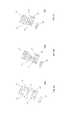
- FIG. 2Aillustrates a retina auto-focus technique employed by an embodiment of the present invention.
- FIG. 2Billustrates another retina auto-focus technique employed by an embodiment of the present invention.
- FIG. 2Cillustrates yet another retina auto-focus technique employed by an embodiment of the present invention.
- FIG. 3illustrates an embodiment of the present invention with a dual-sensor, two-eye flippable configuration.
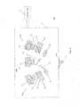
- FIG. 4illustrates an embodiment of the present invention with a triple-sensor, two-eye sequential configuration.
- FIG. 5illustrates an embodiment of the present invention with a single-sensor, two-eye sequential configuration.
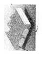
- FIG. 6Aillustrates an external view of an embodiment of the present invention that captures iris images from both eyes.
- FIG. 6Billustrates another external view of the embodiment of FIG. 6A .
- FIG. 6Cillustrates the use of corrective eyewear with the embodiment of FIG. 6A .
- FIG. 6Dillustrates an internal view of the embodiment of FIG. 6A .
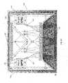
- FIG. 7illustrates an exemplary fixation scheme as seen by the user.
- FIG. 8Aillustrates another exemplary fixation scheme, as seen by the user when the user is misaligned along the X-, Y-, and Z-axes.
- FIG. 8Billustrates another exemplary fixation scheme, as seen by the user, when the user is misaligned along the Z-axis.
- FIG. 8Cillustrates another exemplary fixation scheme, as seen by the user when the user is aligned along the X-, Y-, and Z-axes.
- FIG. 9illustrates an exemplary scheme for entering a personal identification number by pupil tracking.
- Embodiments of the present inventionprovide a multimodal ocular biometric system that captures and processes images of both the iris and the retina, from which data can be determined for biometric identification. Further embodiments provide a multimodal ocular system that captures and processes images of the iris and/or the retina from both eyes of a subject. Biometrics based on data provided by these embodiments are more accurate and robust than using biometrics that include data from only the iris or only the retina from a single eye.
- the iris and retinapresent biometric features that are both independent and strongly coupled. They are independent in that they are extracted from different biological structures.
- the iris and retina biometric featuresare strongly coupled because there is a fixed geometric relationship between the iris and the retina. Specifically, the position and orientation of the eye is reflected simultaneously in both the iris and the retina. Further, the biometric features of the iris and the retina are on the same scale. The strong coupling between the biometric features of the iris and the retina not only facilitates the simultaneous capture of these biometric features, but allows these features to be cross-referenced or combined in a common feature space that preserves the geometric relationship between the iris and retina.
- the use of an iris systemcomplements the use of a retina system. For instance, small pupils are generally an advantage for iris systems while large pupils are generally an advantage for retina systems.
- FIG. 1illustrates a two-eye simultaneous iris/retina combination system, which employs two iris imaging systems that respectively capture iris images of the right and left eyes, and two retinal imaging systems that respectively capture the images of the right and left retina, all simultaneously, or at least substantially simultaneously.
- Information from the imaging systemsis used to accomplish retinal pattern recognition, iris pattern recognition, and biometric fusion.
- the information from the individual imaging systemsare used in combination to establish a host of attributes including, but not limited to, positioning, tracking, focus, and interpupillary distance.
- the multimodal ocular biometric systemis especially well suited for image capture of both eyes when the user is not wearing corrective eyewear.
- many of the features of the present inventionmay be described with respect to the two-eye simultaneous iris/retina combination system shown in FIG. 1 , other configurations, as described further below, can implement these features in order to combine iris and retina images for biometric identification.
- the multimodal ocular biometric system 10includes an optical system which is symmetric for both the left eye 2 and the right eye 4 .
- the multimodal ocular biometric system 10includes two camera sensors 110 to capture respective images of the iris in the right and left eyes.
- the system 10also has two camera sensors 210 to capture respective images of the retina in the right and left eyes.
- an iris imaging system 100 and a retina imaging system 200are provided for each eye. Therefore, iris and retina images can be captured simultaneously, or at least substantially simultaneously.
- the iris imaging systems 100 and the retina imaging system 200are housed in a single image capture device 12 , as depicted in FIG. 1 .
- the biometric information collected from the system 10includes iris patterns and retina patterns, from which biometric data can be extracted. Liveness detection, which detects whether the biometric information comes from a living source, may also be achieved with the system 10 .
- the system 10is able to provide biometrics, such as interpupillary distance and limbus diameter for both the right and left eyes.
- biometricssuch as interpupillary distance and limbus diameter
- measurements of the interpupillary distance and limbus diametercan be used to improve database searching during biometric identification, because they allow reference data to be binned and narrowed to a relevant subset of data before a search is conducted for matches based on iris codes or retinal codes. In this way, a comprehensive search of all reference data for biometric matching is not required.
- limbus diameters for the general populationhave a range of about 9.5 mm to 13.5 mm.
- the system 10measures a limbus diameter to be 10.5 mm
- a subset of reference data covering individuals with limbus diameters in a range of 10.25-10.75 mm, rather than the entire database,may be searched.
- the time to obtain a match with the reference datamay improve by up to 8 times when narrowing the data down according to ranges of limbus diameter in this manner.
- interpupillary distances for the general populationhave a range of ⁇ 10 mm. Obtaining a ⁇ 1 mm resolution would thus improve search times by up to a factor of 10.
- narrowing the search data according to limbus diameter and the interpupillary distancemay improve search times by 80 (8 ⁇ 10), which may be significant for very large databases.
- throughputcan be enhanced by system memory caching based on bins for mid-sized databases in multi-machine systems. Considering N interpupillary distance bins, if N machines with N local system memories each have enough system memory to hold the entire bin for an interpupillary distance in the database, then database access is less likely to become a system bottleneck.
- the multimodal ocular biometric system of the present inventionemploys both iris illumination adapted to emit photons to the iris of an eye and retina illumination adapted to emit photons to the retina of the eye.
- the embodiment shown in FIG. 1employs LEDs (light emitting diodes) 120 and 220 to produce iris illumination and retina illumination, respectively.
- FIG. 1also shows that the iris and retina illumination uses separate LED's.
- the camera sensors 110are configured to capture iris images when the right and left irises reflect the emitted light from the illumination source 120
- the camera sensors 210are configured to capture retina images when the right and left retinas reflect the emitted light from the illumination source 220 .
- embodiments of the present inventionmay employ laser diodes rather than LEDs.
- the systemcan perform laser Doppler imaging using an addressable CMOS detector on specific regions of interest.
- this approachpermits retinal liveness testing as well as retina vessel determination and contrast enhancement.
- a controller 15is operably connected to the iris illumination and the retina illumination, such as LED's 120 and 220 .
- the controller 15manages the manner in which the iris illumination and the retina illumination emits photons to the irises or the retinas, respectively.
- the controller 15may be a programmable processing device that executes software, or stored instructions.
- the controller 15may employ an external conventional computer networked with the image capture device 12 .
- a field programmable gate array (FPGA) or digital signal processor (DSP)may be employed on board the image capture device 12 .
- the systems described hereinmay employ a controller, as well as other processors, that are either internal or external to the image capture devices, which house the illumination and sensor systems.
- the wavelengths for illumination of the iris and retinamay be in the near infrared (NIR) (700 nm to 1000 nm). Special filters or coated optics may be used in the optical train to select specific wavelengths to satisfy the 700 nm to 900 nm wavelength requirements for the ANSI specification for Iris Image Interchange Format (ANSI INCITS 379-2004), but still allow a visible color image.
- NIRnear infrared
- Special filters or coated opticsmay be used in the optical train to select specific wavelengths to satisfy the 700 nm to 900 nm wavelength requirements for the ANSI specification for Iris Image Interchange Format (ANSI INCITS 379-2004), but still allow a visible color image.
- the iris illumination system of the present inventionmay operate to illuminate just the inner orbit of the eye.
- the area of interest outside the field of view (FOV) of the iris camera 110is not over-illuminated, as illumination outside the FOV can cause reflections off the cheek, forehead, or nose creating non-uniform illumination of the iris. This is especially the case for people who wear makeup containing TiO 2 .
- illuminating the area outside the FOV of the camerais a waste of light and energy.
- Two arrays of LEDs 120 at a wavelength of 850 nm, for example,are masked and focused on the iris and sclera in order to create this uniform illumination.
- the illuminationoccurs at an angle of approximately ⁇ 15 degrees measured from the line of sight of the user in order to minimize retro-reflection off the retina with the associated bright pupil corresponding to the iris image.
- the pupilmust remain dark for image analysis and to meet ANSI INCITS specification.
- the irispasses through a broadband antireflection coated optical window 330 and is imaged back through the imaging system, through a dichroic beamsplitter 130 .
- the lightthen passes through a plastic or glass longpass filter 180 with a cutoff wavelength of 780 nm, for example.
- the longpass filter 180prevents ambient visible light from entering the imaging system and creating noise in the image.
- the lightis then focused with the iris imaging lens 190 to the image sensor 110 .
- the sensor 110is a CMOS (complementary metal-oxide semiconductor) detector with high sensitivity to NIR illumination.
- the CMOS detectormay have square pixels, a wide angle format, and a global shutter.
- the iris imaging system of the present inventionmay have a refractive lens (a single or a series of lenses) 190 which images the iris to a CMOS image sensor 110 or, alternatively, a CCD (charge-coupled device) sensor 110 .
- the image capture device 12may also employ reflective or a combination of refractive and reflection optics.
- the imaging sensor 110may also have a global shutter or a rolling shutter.
- embodimentsmay include an iris imaging system which uses digital processing algorithms for pupil tracking and iris focus measurement.
- a pupil tracking algorithmmay employ segmentation, e.g. a caliper technique, to determine pupil position.
- segmentatione.g. a caliper technique
- an example of an algorithm for iris focus measurementis disclosed in application Ser. No. 11/526,096, filed on Sep. 25, 2006, which is entirely incorporated herein by reference.
- the three dimensional position of the iris with respect to the device 12is determined for both left and right eyes.
- information regarding position along X- and Y-axesmay be determined from the pupil tracking and information regarding position along the Z-axis may be determined from the iris focus measurement. Evaluation of this position data may determine when images of acceptable quality have been captured and should be utilized for biometric data.
- the retina illuminationmay employ a tracking system to illuminate the optic nerve head of the retina.
- arrays of LED's 220 at a wavelength of 880 nm spaced 1 mm apartare aligned to 1 mm diameter and 10 mm long hollow tubes.
- the hollow tubescreate a homogenizing waveguide for the light emanating from them. Only a single element of the array is illuminated at a time corresponding to the determination of the pupil's position in space, as determined by the digital processing algorithms, including segmentation and focus measure. As such, analysis of the iris image yields pupillary positional information that may be employed to determine illumination of the corresponding retina.
- the pupil's positionis used to determine which LED 220 in the array aligns most optimally with the retina and should be activated for illumination of the retina.
- Reference numeral 225 in FIG. 1illustrates a diffuser, which is placed over the ends of the tubes to create a 1 mm spot from the active LED 220 .
- reference numeral 225may refer to an LCD shutter, which can create a similar 2-dimensional series of singly activated illuminators that are 1 mm in diameter and imaged to the eye. Depending on the determination of the pupil's position in space, the LCD shutter 225 allows light from the illumination source 220 to pass through an appropriate section of the LCD device 225 to illuminate the retina. As further alternatives, scanning micro-optics or holographic elements may also be employed.
- the light from the LCD shutter/diffuser/micro-optics 225reflects off a polarizing beamsplitter (PBS) 230 creating S polarized light.
- PBSpolarizing beamsplitter
- This lightis then imaged by the aspheric objective lens 240 , through a long pass plastic sheet filter with a 780 nm cutoff wavelength, to a 2 mm spot just before the nominal position of the cornea.
- the angle of the light entering the pupilis nominally 15.5 degrees temporal to and 1.5 degrees inferior to the line of sight of the user.
- the spot diameteris chosen to be smaller than the pupil so that light does not scatter off its edges causing excess noise in the retina image.
- the divergence of the lightis approximately 10 degrees half angle.
- the retina imageconsists of the blood vessel pattern emanating from the optic nerve head. Absorption of the light by hemoglobin and oxyhemoglobin in the blood creates the outline of the blood vessel pattern. Demarcation of the optic nerve head may or may not be discernable.
- the LED'shave three pulse duration settings that are cycled through (exposure bracketing) so as to accommodate for reflectance differences of the retina in the general population.
- the light reflecting off the retinapasses back through the long pass cutoff filter.
- This filterprevents ambient visible light from entering the imaging system and creating noise in the image. It also hides the imaging optics from the user.
- the lightis then collected by the aspheric objective lens 240 to produce a real image just before the polarizing beamsplitter 230 .
- This real imageis then imaged though the PBS 230 allowing only P polarized light to pass.
- the purpose of the PBS 230is to increase the signal to noise ratio of the signal by rejecting any S polarized light reflected back through the system from other optical surfaces.
- An imaging lens followed by a cubic phase mask opticthen images the light onto a camera sensor 210 .
- the camera sensor 210may be a CMOS detector with high sensitivity to NIR illumination.
- the CMOS detectorhas square pixels, has a wide angle format, and has a global shutter.
- the images of the retinaare multiplied by specific digital filters. These filters are created for differences in dioptric power correction.
- the imagesare evaluated using a retina focus measure algorithm and the one with the highest contrast image is preferably utilized for biometric identification.
- An example of a retinal focus measure algorithmis described in application Ser. No. 11/785,924, filed Apr. 20, 2007, which is entirely incorporated herein by reference.
- the illumination for the irismay have a different wavelength from the illumination for the retina.
- the retinais illuminated with light of a first wavelength, the light of the first wavelength being reflected from the retina to the retina image capturing device.
- the irisis illuminated with light of a second wavelength that is different from the first wavelength, the light of the second wavelength being reflected from the iris to the iris image capturing device.
- the first wavelength of lightis selected to provide enhanced contrast between biometric features of the retina, such as a retinal vessel pattern, and the background in the captured image.
- the second wavelength of lightis selected to provide enhanced contrast for the biometric features of the iris.
- the iris illumination and the retina illuminationoccur at the same time or in near time, however, the iris illumination can introduce noise in the retina signal, or vice versa.
- dichroic opticscan be employed to allow wavelength separation from the different illumination sources, where light of one wavelength is directed to one sensor while light of a second wavelength is directed to another sensor.
- the illumination with special dichroic opticscan be pulsed or run as a continuous wave.
- the iris illumination and the retina illuminationcan be separated by pulsing the individual LEDs with a synchronized offset.
- the iris and retina camerascan run at 30 frames per second offset by half a frame (16.5 ms) with a shutter (global, rolling or global-rolling hybrid) of 10 ms.
- the pulses from the LEDsoccur at 10 ms so that neither camera sees light from the other illumination LEDs.
- the advantage of pulsing illumination with a synchronous offsetis that it freezes motion, maximizes frame rate without having to use dichroics, and allows higher pulse energies which reduces gain on the camera, thereby increasing image quality.
- pulsing illumination with a synchronous offsetpermits the use of the same wavelength for the illumination of the iris and retina.
- both iris and retina illuminationmay use auto gain in order to correct for the proper exposure for correction of reflectance differences of the iris and retina.
- both iris and retina illumination bracketing(or exposure bracketing) may be used instead of auto gain.
- pulse duration 1pulse 1
- pulse duration 2pulse 2
- pulse duration 3pulse 3
- cyclepulse 1 , pulse 2 , pulse 3 , pulse 1 , pulse 2 , pulse 3 , . . . an so on.
- the iris illuminationcan advantageously be pulsed at less than half the frame rate of the iris and retina cameras.
- the frame rates for both camerasare identical.
- the image of the irisis analyzed with the pupil tracking and iris focus measure digital processing algorithms.
- the X 1 , Y 1 , and Z 1 positions of the pupil of the irisare calculated.
- the usermust move through the nominal Z N position of the system which establishes the absolute position of the user. Until that time, the system assumes a relative position of the pupil based on pupil size. Iris images that are adequately in focus are collected and analyzed appropriately.
- the LED'shave three power settings that are cycled through (exposure bracketing) so as to accommodate for reflectance differences of the iris in the general population.
- the positional information of the pupilis utilized to select the addressable retinal illumination LED that will cleanly enter the pupil.
- the retina illumination LEDis pulsed at half a frame out of phase from the iris illumination.
- the pulse durationis less than half the frame rate.
- the present inventionmay also employ a retina auto focus mechanism, which corrects for changes in retinal focus due to differences in uncorrected dioptric power and allows any corrective optical devices to be removed by the user. Corrective optical devices can cause aberrations and glare. Several techniques may be applied to achieve retina auto focus.
- one technique for retina auto focusemploys a motor 292 that moves the focus of the retina imaging lens 290 in specific dioptric value increments, along the arrow A as shown in FIG. 2A .
- the systemutilizes a retina focus measure algorithm comparing successive positions. If the system remains out of focus, the system uses this comparison to determine the direction in which it should move.
- FIG. 2Billustrates a retina imaging system 200 B with an imaging lens with a cubic phase plate, indicated by reference numeral 294 . Contrary to the use of the motorized lens, there are no moving parts with wavefront coding. A cubic phase mask is placed in the system and the system is fully characterized with regard to dioptric power correction. Differences in dioptric power correction are calculated and specific digital filters are created for each dioptric power. When an image is taken, each of the filters is convolved with the image and the one with the highest contrast image is utilized. This configuration provides a robust system, which can be used at extreme temperatures, because there are no moving parts.
- a third technique for retina auto focususes an electroactive optical element 296 , which is a liquid crystal sandwiched between two pieces of glass with a specific electrode configuration on them. By activating the electrodes with different voltages, either a positive or negative dioptric correction may be created. This can be a single device or a stack of devices to create larger dioptric correction.
- the multimodal ocular biometric systemmay be handheld, but may also be attached to an articulating arm, attached to or embedded into an immovable object such as a wall, or adapted to an existing optical system such as a rifle scope or tank periscope.
- the systemmay possess a simple fixation system, or interface, to position the user. For instance, with an exemplary handheld embodiment, the user picks up the device and removes any eyeglasses the user may be wearing. The user then identifies a fixation illumination source within the device and carefully positions the device with respect to his or her face according to the fixation illumination source.
- the outer housing of the devicemay be designed to help center the user as well as to provide light baffling of external ambient light.
- the useroperates the image capture device 12 by identifying the fixation light source 310 through the broadband antireflection coated windows 330 .
- the light from the source 310reflects off the beamsplitter and cold mirror 320 .
- a circular target 62 with cross hairs 64is viewed through an imaging lens with two illuminated bars 66 above and below the lens.
- the illuminated bars 66are positioned at the exit pupil of the device 12 .
- the bars 66may include a diffusing light guide with colored LEDs illuminating them.
- the circular target 62is a reticule with a diffuser and colored LEDs behind it.
- the useroperates the fixation system 60 by moving the device 12 relative to his or her eyes to center the circle 62 between the two bars 64 . As the user moves back and forth relative to the device 12 , different colored combinations may help guide his or her movement.
- the image capture device 12may also employ provide positional feedback to the user by using the pupil tracking and iris focus measure digital processing algorithms.
- a retina focus measure digital processing algorithmcan be used in place of, or in combination with, an iris focus measure digital processing algorithm.
- an interfaceprovides a set of central cross hairs 72 designating nominal positioning (X N , Y N , Z N ) for optimal alignment by the user relative to the device 12 and a second set of cross hairs 74 with a circle 76 designating the user's present position (X 1 , Y 1 , Z 1 ).
- X N , Y N , Z Nnominal positioning
- the diameter of the circle 76becomes larger as the user moves away from the nominal Z N position and smaller as the user moves towards the nominal Z N position.
- the circle 76disappears, the user is positioned at the nominal Z N position.
- the image of FIG. 8Aindicates that the user is misaligned along the X-, Y-, and Z-axes.
- the image of FIG. 8Bindicates that the user is aligned along the X- and Y-axes, but misaligned along the Z-axis.
- the interfaceshows the image of FIG. 8C , the user has achieved the nominal position (X N , Y N , Z N ). Auditory feedback may be additionally employed with the fixation system 70 , signaling the user with appropriate tones and/or verbal instructions to move the user into optimal alignment.
- embodiments of the present inventionmay include, in combination with the fixation system, a clock interface 80 that accepts a pin number for further identification.
- a clock interface 80that accepts a pin number for further identification.
- userslook into the device, they begin by looking at a start position. They then enter their pin number by fixating on the numbers or other symbols 82 .
- the systemuses the pupil tracking to determine the trajectory of the different pupil positions to identify each number or symbol 82 entered by the user. Verification of each number or symbol 82 can be indicated through aural tones and/or visible color changes, as illustrated by number 83 in FIG. 9 .
- a left-eye only configurationemploys iris and retina imaging systems to capture images of the left eye only.
- a right-eye only configurationemploys iris and retina imaging systems to capture images of the right eye only.
- a dual sensor, two-eye “flippable” system 20provides one iris imaging system 400 and one retina imaging system 500 in an image capture device 22 that can be oriented to capture images of both the left and right eyes, in succession.
- the same iris imaging system 400 and retina imaging system 500are used to capture images of the left and right eyes.
- the userflips, or turns the device over, to capture images of the second eye. Flipping the device over maintains the correct orientation of the iris and retina imaging systems with respect to the eye. For example, the specific orientation shown in FIG. 2 permits the capture of images from the right eye 4 .
- the iris imaging system 400 in FIG. 3employs a camera sensor 410 which captures images of the illuminated iris through a dichroic beamsplitter 430 .
- the retina imaging system 500 in FIG. 3employs an illumination source 520 that provides light that is guided through a LCD shutter/diffuser/micro-optics 525 , a polarizing beamsplitter (PBS) 530 , and an aspheric objective lens 540 to the retina. Furthermore, the image of the retina then passes back through the aspheric objective lens 540 and the PBS 530 to the camera sensor 510 .
- PBSpolarizing beamsplitter
- the system 20employs a dual fixation LED with orientation sensor 525 , where one of the two LED's is activated according to the “flipped” orientation of the device 22 .
- An orientation sensorsenses the orientation of the device 22 and correspondingly turns on the appropriate fixation LED.
- the system 20 as shown in FIG. 3also uses a dual retina/iris illumination and retina illumination tracking configuration.
- the illumination source 520provides illumination of the iris as well as the retina.
- the retina illumination system in this embodimentis similar to the illumination system for the retina in the two-eye simultaneous system 10 shown in FIG. 1 , where the element of the LED array is illuminated according to the pupil's position in space.
- the captured iris imageis used to track the position of the pupil in order to identify the specific LED that should be used to provide the necessary pinpoint illumination of the retina in the subsequent image capture.
- both the retina illumination and iris illuminationemanate through the retina imaging optics.
- the addressable light source array 520is used to create pulsed light for both iris and retina illumination.
- All elements in the array 520are employed to illuminate the iris. Then, using the pupil tracking digital processing algorithm and iris focus measure digital processing algorithm, selected elements in the array are turned on to illuminate the retina. As the position of the iris moves the appropriate elements in the array are selected for both the retina and iris. For the retina illumination, the illumination elements of the array imaged (to just before the retina) are smaller than the pupil of the iris.
- this illumination configurationenables simplification of the packaging, minimizes reflections off the orbit of the eye for uniform iris illumination, and allows scanning of the retina for increased volume of alignment.
- the addressable light source arraycan be built in several different configurations, including, but not limited to, the use of an LED array with light guides and diffuser and an LCD shutter, scanning micro-optics, and holographic elements, as indicated by reference numeral 525 .
- a triple sensor, two-eye sequential system 30employs one iris imaging system 600 and two retina imaging systems 700 in device 32 to capture sequential, or successive, images of both the left and right eyes.
- the same iris imaging system 600is used to image the iris of both the left and right eyes, while two retina imaging systems 700 with specific left and right orientations are used to image the left and right eyes, respectively.
- the system 30 of FIG. 4does not have to be flipped, or turned over, to capture images of the second eye. Thus, it easier to reposition for capture of images from the second eye, because the same horizontal plane can be maintained.
- a dual fixation LED with orientation sensordoes not have to be employed. Rather, a single fixation source 310 may be employed.
- the iris imaging system 600 in FIG. 4employs a camera sensor 610 which captures images of the illuminated iris through a dichroic beamsplitter 630 .
- the retina imaging system 700 in FIG. 4employs an illumination source 720 that provides light that is guided through a LCD shutter/diffuser/micro-optics 725 , a polarizing beamsplitter (PBS) 730 , and an aspheric objective lens 740 to the retina. Furthermore, the image of the retina then passes back through the aspheric objective lens 740 and the PBS 730 to the camera sensor 710 .
- PBSpolarizing beamsplitter
- a single-sensor, two-eye sequential system 40includes a single sensor 810 in device 42 to capture both the retina and iris images by employing pulse separation and different wavelengths for the iris and retina.
- the two coated surfaces on the single opticpermit sequential detection of ⁇ 1 , ⁇ 2 , ⁇ 3 , and ⁇ 4 and capture of alternating images of the iris and retina.
- several optical systemscan be used to get the images of both eyes on a single detector array.
- the system 40 shown in FIG. 5employs an LED array 820 , a LCD shutter/micro-optics/diffuser 825 , a polarizing beamsplitter (PBS) 830 , an aspheric objective lens 840 , and a single fixation source 310 .
- PBSpolarizing beamsplitter
- a compensating lens 865is additionally used in order to form images of the retina and the iris on the same camera sensor 810 .
- the compensation lensallows for proper image magnification for the capture of the iris by camera sensor 810 .
- the system 40uses a dual retina/iris illumination and retina illumination tracking configuration.
- the advantage of this systemis that it uses a single sensor and fewer parts.
- the disadvantageis that the system runs at half the frame rate for iris and retina image capture being every other frame respectively. In other words, halving the frame rate yields half the number of images of the retina and the iris, so it may be more difficult to obtain adequate images.
- this particular configurationmust also be flipped like the dual sensor, two-eye flippable configuration shown in FIG. 2 .
- Interpupillary distance measurementcan be determined, providing an additional biometric.
- the (X, Y, Z) position of each pupilcan be used to calculate pupil separation.
- this particular biometricis used to reduce database searching for iris matching, retina matching and iris retina fusion matching. Additional on axis illumination of the iris can also enable bright pupil back reflection (“red eye”) that can enhance the iris/retina tracking algorithms.
- FIGS. 6A-Dshow a device 50 adapted to simultaneously accommodate both eyes of a user, similar to a pair of binoculars, and capture images of both irises. As shown in FIGS. 6A-D , the user employing the device 50 is able to see through the device 50 to view an object external to the device 50 as a target.
- the device 50may be employed without a fixation illumination source.
- the device 50employs a fixation system where the exit pupil matches or is slightly larger than the entrance pupil of the eye for a given eye relief.
- an elliptical, or near elliptical, exit pupilis used to accommodate interpupillary distance. This maintains vertical alignment and allows vergence by the user to maintain horizontal alignment.
- the targetmay be an image which appears to be at a distance.
- thiscauses the brain to allow the eye to relax to its unaccommodated state.
- FIG. 6Ashows the biometric device 50 with housing 900 .
- usersbegin by looking through the user windows 902 and bringing the device 50 closer to their eyes until they are able to use their vergence to visually fuse the exit pupils of the device 50 .
- This approachaligns most users to a given image plane with or without eyeglasses.
- the device 50also has opposing windows 904 facing the opposing user windows 902 .
- the opposing windows 904not only permit an image of the target on the other side of the device 50 to be seen by the user, but the opposing windows also allow one to see the eyes of the user positioned at user windows 902 .
- the device 50in addition to operation of the device 50 directly by the user, the device 50 also permits operation by another person who holds the device 50 at the user's face and aligns it to the user's eyes from the other side.
- the device 50allows an operator to assist a user during alignment and operation of the device 50 .
- the device 50helps to ensure proper alignment about at least two axes of rotation in order to achieve a better biometric.
- the device 50helps to ensure proper alignment about at least two axes of rotation in order to achieve a better biometric.
- the X-, Y-, and Z-axes shown in FIG. 6Awhen users bring the device 50 to their face, they have to position the device 50 so that they can see through both user windows 902 , thus ensuring proper alignment about the Z-axis.
- usersnaturally position the device 50 so that the user windows 902 are approximately the same distance from each respective eye, which ensures proper alignment about the Y-axis.
- the exit pupilscan then be elliptical, or slit-like, to minimize-any misalignment about the X-axis.
- a linear horizontal diffraction gratingor equivalent “microlouver” technology, may be placed on user windows 902 in order to limit the field of view of the user or operator and ensure proper alignment along the vertical Y-axis.
- a second vertical diffraction gratingmay also be employed to also ensure proper alignment along the horizontal X-axis.
- the combination of horizontal and vertical gratingslimits the field of view vertically and horizontally.
- a semitransparent targetmay be placed behind the gratings for additional alignment indicators.
- FIG. 6Dillustrates an arrangement of components that may be employed by device 50 to capture images of the irises of both eyes positioned at user windows 902 .
- Two camera sensors 910 with filters 912are positioned on opposite (right and left) sides in the interior of the device 50 to capture respective images of the right and left eyes.
- the LEDs 920provide near infrared illumination to the iris of each eye. The illumination is reflected from the irises back to the respective beamsplitters 930 .
- the beamsplitters 930may be “hot” mirrors which redirect the near infrared light reflected from the irises to the respective camera sensors 910 , but which allow visible light to pass through to the operator windows 904 so that an operator can see the user's eyes.
- White light illumination from the white light illumination sources 950may be employed to close down the pupil of the user to provide better biometric data and to help illuminate the eye for alignment by an operator. As shown in FIGS. 6A and 6D , the area 922 of near infrared light cast by the LEDs 920 is smaller than area 952 of white light cast by sources 950 . With a smaller area 922 , the amount of near infrared light reflected from the area outside the iris, such as the user's cheeks, is minimized.
- the device 50may accommodate the individual's eyeglasses 7 , as illustrated in FIG. 6C .
- the individual's eyeglasses 7may be combined with the device 50 beyond the beamsplitters 930 but in a position where the eyeglasses can sufficiently correct the person's vision in order to use the device 50 and view the external object. Accordingly, illumination and image capture are not affected by the eyeglasses.
- a device similar to the device 50 illustrated in FIGS. 6A-Dmay be used to capture images of the retina from both eyes.
- another similar devicemay be employed to capture images of both the iris and the retina of both eyes, in a manner similar to embodiments described previously.
- the controller 15may be a programmable processing device, such as an external conventional computer networked with the device 12 or an on-board field programmable gate array (FPGA) or digital signal processor (DSP), that executes software, or stored instructions. Controllers 25 , 35 , and 45 shown in FIGS. 3 , 4 , and 5 , respectively, may be similarly configured.
- FPGAfield programmable gate array
- DSPdigital signal processor
- physical processors and/or machines employed by embodiments of the present invention for any processing or evaluationmay include one or more networked or non-networked general purpose computer systems, microprocessors, field programmable gate arrays (FPGA's), digital signal processors (DSP's), micro-controllers, and the like, programmed according to the teachings of the exemplary embodiments of the present invention, as is appreciated by those skilled in the computer and software arts.
- the physical processors and/or machinesmay be externally networked with the image capture device, or may be integrated to reside within the image capture device.
- Appropriate softwarecan be readily prepared by programmers of ordinary skill based on the teachings of the exemplary embodiments, as is appreciated by those skilled in the software art.
- the devices and subsystems of the exemplary embodimentscan be implemented by the preparation of application-specific integrated circuits or by interconnecting an appropriate network of conventional component circuits, as is appreciated by those skilled in the electrical art(s).
- the exemplary embodimentsare not limited to any specific combination of hardware circuitry and/or software.
- the exemplary embodiments of the present inventionmay include software for controlling the devices and subsystems of the exemplary embodiments, for driving the devices and subsystems of the exemplary embodiments, for enabling the devices and subsystems of the exemplary embodiments to interact with a human user, and the like.
- softwarecan include, but is not limited to, device drivers, firmware, operating systems, development tools, applications software, and the like.
- Such computer readable mediafurther can include the computer program product of an embodiment of the present inventions for performing all or a portion (if processing is distributed) of the processing performed in implementing the inventions.
- Computer code devices of the exemplary embodiments of the present inventionscan include any suitable interpretable or executable code mechanism, including but not limited to scripts, interpretable programs, dynamic link libraries (DLLs), Java classes and applets, complete executable programs, and the like. Moreover, parts of the processing of the exemplary embodiments of the present inventions can be distributed for better performance, reliability, cost, and the like.
- interpretable or executable code mechanismincluding but not limited to scripts, interpretable programs, dynamic link libraries (DLLs), Java classes and applets, complete executable programs, and the like.
- Computer-readable mediamay include, for example, a floppy disk, a flexible disk, hard disk, magnetic tape, any other suitable magnetic medium, a CD-ROM, CDRW, DVD, any other suitable optical medium, punch cards, paper tape, optical mark sheets, any other suitable physical medium with patterns of holes or other optically recognizable indicia, a RAM, a PROM, an EPROM, a FLASH-EPROM, any other suitable memory chip or cartridge, a carrier wave or any other suitable medium from which a computer can read.
- a floppy diska flexible disk, hard disk, magnetic tape, any other suitable magnetic medium, a CD-ROM, CDRW, DVD, any other suitable optical medium, punch cards, paper tape, optical mark sheets, any other suitable physical medium with patterns of holes or other optically recognizable indicia, a RAM, a PROM, an EPROM, a FLASH-EPROM, any other suitable memory chip or cartridge, a carrier wave or any other suitable medium from which a computer can read.
- the positions of the iris camera and the fixation illumination source in embodiments abovemay be switched by the use of a “hot” mirror which reflects the iris image.
- the positions of the retina camera and the retina illuminationmay be switched by illuminating the retina with P polarized light and imaging the S polarized light.
- embodimentsmay capture retina images from both eyes, only the best retinal image from both eyes may be retained to ensure useable retinal biometric data.
- the embodimentproduces data regarding the pupillary distance as well as biometric data from both irises and one of the two retina.
- the multimodal ocular biometric system of the present inventionis not limited to human identification and can be used for animal identification.
Landscapes
- Health & Medical Sciences (AREA)
- Life Sciences & Earth Sciences (AREA)
- Engineering & Computer Science (AREA)
- Physics & Mathematics (AREA)
- General Health & Medical Sciences (AREA)
- Ophthalmology & Optometry (AREA)
- Surgery (AREA)
- Medical Informatics (AREA)
- Molecular Biology (AREA)
- Biomedical Technology (AREA)
- Animal Behavior & Ethology (AREA)
- Biophysics (AREA)
- Public Health (AREA)
- Veterinary Medicine (AREA)
- Heart & Thoracic Surgery (AREA)
- Multimedia (AREA)
- Human Computer Interaction (AREA)
- General Physics & Mathematics (AREA)
- Theoretical Computer Science (AREA)
- Signal Processing (AREA)
- Measurement Of The Respiration, Hearing Ability, Form, And Blood Characteristics Of Living Organisms (AREA)
- Eye Examination Apparatus (AREA)
- Collating Specific Patterns (AREA)
Abstract
Description
Claims (47)
Priority Applications (3)
| Application Number | Priority Date | Filing Date | Title |
|---|---|---|---|
| US11/798,500US8014571B2 (en) | 2006-05-15 | 2007-05-14 | Multimodal ocular biometric system |
| US13/196,617US8391567B2 (en) | 2006-05-15 | 2011-08-02 | Multimodal ocular biometric system |
| US13/753,155US8983146B2 (en) | 2006-05-15 | 2013-01-29 | Multimodal ocular biometric system |
Applications Claiming Priority (4)
| Application Number | Priority Date | Filing Date | Title |
|---|---|---|---|
| US80002306P | 2006-05-15 | 2006-05-15 | |
| US81294906P | 2006-06-13 | 2006-06-13 | |
| US81963006P | 2006-07-11 | 2006-07-11 | |
| US11/798,500US8014571B2 (en) | 2006-05-15 | 2007-05-14 | Multimodal ocular biometric system |
Related Child Applications (1)
| Application Number | Title | Priority Date | Filing Date |
|---|---|---|---|
| US13/196,617DivisionUS8391567B2 (en) | 2006-05-15 | 2011-08-02 | Multimodal ocular biometric system |
Publications (2)
| Publication Number | Publication Date |
|---|---|
| US20080044063A1 US20080044063A1 (en) | 2008-02-21 |
| US8014571B2true US8014571B2 (en) | 2011-09-06 |
Family
ID=39230730
Family Applications (3)
| Application Number | Title | Priority Date | Filing Date |
|---|---|---|---|
| US11/798,500Active2030-07-06US8014571B2 (en) | 2006-05-15 | 2007-05-14 | Multimodal ocular biometric system |
| US13/196,617Expired - Fee RelatedUS8391567B2 (en) | 2006-05-15 | 2011-08-02 | Multimodal ocular biometric system |
| US13/753,155ActiveUS8983146B2 (en) | 2006-05-15 | 2013-01-29 | Multimodal ocular biometric system |
Family Applications After (2)
| Application Number | Title | Priority Date | Filing Date |
|---|---|---|---|
| US13/196,617Expired - Fee RelatedUS8391567B2 (en) | 2006-05-15 | 2011-08-02 | Multimodal ocular biometric system |
| US13/753,155ActiveUS8983146B2 (en) | 2006-05-15 | 2013-01-29 | Multimodal ocular biometric system |
Country Status (2)
| Country | Link |
|---|---|
| US (3) | US8014571B2 (en) |
| WO (1) | WO2008039252A2 (en) |
Cited By (6)
| Publication number | Priority date | Publication date | Assignee | Title |
|---|---|---|---|---|
| US20110150334A1 (en)* | 2008-07-23 | 2011-06-23 | Indian University & Technology Corporation | System and method for non-cooperative iris image acquisition |
| US20130063582A1 (en)* | 2010-01-22 | 2013-03-14 | Hyeong In Choi | Device and method for iris recognition using a plurality of iris images having different iris sizes |
| US8885882B1 (en) | 2011-07-14 | 2014-11-11 | The Research Foundation For The State University Of New York | Real time eye tracking for human computer interaction |
| WO2015131198A1 (en)* | 2014-02-28 | 2015-09-03 | Lrs Identity, Inc. | Dual iris and color camera in a mobile computing device |
| US11080557B2 (en)* | 2018-04-10 | 2021-08-03 | Canon Kabushiki Kaisha | Image authentication apparatus, method, and storage medium using registered image |
| US12277740B2 (en) | 2021-04-29 | 2025-04-15 | Carefusion 303, Inc. | Self-adjusting biometric sensor |
Families Citing this family (61)
| Publication number | Priority date | Publication date | Assignee | Title |
|---|---|---|---|---|
| US8260008B2 (en) | 2005-11-11 | 2012-09-04 | Eyelock, Inc. | Methods for performing biometric recognition of a human eye and corroboration of same |
| US8014571B2 (en)* | 2006-05-15 | 2011-09-06 | Identix Incorporated | Multimodal ocular biometric system |
| WO2008147914A2 (en)* | 2007-05-26 | 2008-12-04 | Andrew Peter Davis | Binocular indirect ophthalmoscope fixation light |
| WO2009029757A1 (en) | 2007-09-01 | 2009-03-05 | Global Rainmakers, Inc. | System and method for iris data acquisition for biometric identification |
| US9117119B2 (en) | 2007-09-01 | 2015-08-25 | Eyelock, Inc. | Mobile identity platform |
| US9036871B2 (en) | 2007-09-01 | 2015-05-19 | Eyelock, Inc. | Mobility identity platform |
| US8212870B2 (en) | 2007-09-01 | 2012-07-03 | Hanna Keith J | Mirror system and method for acquiring biometric data |
| US9002073B2 (en) | 2007-09-01 | 2015-04-07 | Eyelock, Inc. | Mobile identity platform |
| US20090092292A1 (en)* | 2007-10-05 | 2009-04-09 | Carver John F | Eye Scanner with Integrated Focus Distance Determination Mechanism |
| WO2010056542A1 (en)* | 2008-10-29 | 2010-05-20 | Cross Match Technologies, Inc. | Apparatus for iris capture |
| US20100278394A1 (en)* | 2008-10-29 | 2010-11-04 | Raguin Daniel H | Apparatus for Iris Capture |
| US8434869B2 (en)* | 2009-07-03 | 2013-05-07 | Andrew P. Davis | Automated locking apparatus for a slit lamp |
| US8289300B2 (en) | 2009-07-17 | 2012-10-16 | Microsoft Corporation | Ambient correction in rolling image capture system |
| GB201000973D0 (en) | 2010-01-21 | 2010-03-10 | Glynn Chris | Non-evasive spectrophotometer and related method |
| RU2589859C2 (en) | 2011-02-17 | 2016-07-10 | АЙЛОК ЭлЭлСи | Efficient method and system for obtaining image data of scene and iris image using one sensor |
| US20130089240A1 (en)* | 2011-10-07 | 2013-04-11 | Aoptix Technologies, Inc. | Handheld iris imager |
| US20130088583A1 (en)* | 2011-10-07 | 2013-04-11 | Aoptix Technologies, Inc. | Handheld Iris Imager |
| WO2013056001A1 (en)* | 2011-10-12 | 2013-04-18 | Carnegie Mellon University | System and method for the long range acquisition of iris images for stationary and mobile subjects |
| FR2984565A1 (en)* | 2011-12-19 | 2013-06-21 | Thomson Licensing | METHOD AND DEVICE FOR ESTIMATING THE OPTICAL POWER OF LENSES OF CORRECTIVE GLASSES OF A PAIR OF LENSES CARRIED BY A SPECTATOR. |
| US9138140B2 (en)* | 2012-03-20 | 2015-09-22 | Lrs Identity, Inc. | Compact iris imaging system |
| US9299118B1 (en)* | 2012-04-18 | 2016-03-29 | The Boeing Company | Method and apparatus for inspecting countersinks using composite images from different light sources |
| US10372442B2 (en) | 2013-03-14 | 2019-08-06 | Thoughtwire Holdings Corp. | Method and system for generating a view incorporating semantically resolved data values |
| EP2919641A1 (en)* | 2013-09-30 | 2015-09-23 | Vysoké Ucení Technické V Brne | Ophthalmic diagnostic apparatus and method of its operation |
| CN103800076B (en)* | 2014-01-14 | 2016-02-03 | 中国科学院自动化研究所 | A kind of structure-optics-nucleic multi-mode imaging system and method |
| CN103735252B (en)* | 2014-01-14 | 2016-01-20 | 中国科学院自动化研究所 | A kind of Optical multi-mode state imaging system and method |
| CN103870805B (en)* | 2014-02-17 | 2017-08-15 | 北京释码大华科技有限公司 | A kind of mobile terminal biological characteristic imaging method and device |
| KR102198852B1 (en)* | 2014-03-24 | 2021-01-05 | 삼성전자 주식회사 | Iris recognition apparatus and and mobile apparatus having the same |
| US9639741B2 (en)* | 2014-04-14 | 2017-05-02 | International Business Machines Corporation | Facial recognition with biometric pre-filters |
| CN204129751U (en)* | 2014-05-22 | 2015-01-28 | 宁波舜宇光电信息有限公司 | A kind of iris of both eyes image data acquiring module |
| KR102230691B1 (en)* | 2014-07-09 | 2021-03-23 | 삼성전자주식회사 | Method and device for recognizing biometric information |
| GB2544946B (en) | 2014-08-31 | 2021-03-10 | Berestka John | Systems and methods for analyzing the eye |
| WO2016040836A1 (en)* | 2014-09-12 | 2016-03-17 | Eyelock Llc | Methods and apparatus for directing the gaze of a user in an iris recognition system |
| US9720259B2 (en)* | 2014-10-13 | 2017-08-01 | William Hart | Eyewear pupilometer |
| KR102329814B1 (en)* | 2014-12-01 | 2021-11-22 | 삼성전자주식회사 | Pupilometer for 3d display |
| KR102376954B1 (en)* | 2015-03-06 | 2022-03-21 | 삼성전자주식회사 | Method for irradiating litght for capturing iris and device thereof |
| CN106295287B (en) | 2015-06-10 | 2019-04-09 | 阿里巴巴集团控股有限公司 | Biopsy method and device and identity identifying method and device |
| CN106295270B (en)* | 2015-06-25 | 2019-03-29 | 联想(北京)有限公司 | A kind of user identification method and electronic equipment |
| US10117603B2 (en)* | 2015-06-27 | 2018-11-06 | Intel Corporation | Field-of-view ocular and facial alignment guides |
| US10049272B2 (en) | 2015-09-24 | 2018-08-14 | Microsoft Technology Licensing, Llc | User authentication using multiple capture techniques |
| US10157312B2 (en) | 2015-10-08 | 2018-12-18 | Microsoft Technology Licensing, Llc | Iris recognition |
| US10445606B2 (en) | 2015-10-08 | 2019-10-15 | Microsoft Technology Licensing, Llc | Iris recognition |
| KR20180102637A (en) | 2016-01-12 | 2018-09-17 | 프린스톤 아이덴티티, 인크. | Systems and methods of biometric analysis |
| US9940519B2 (en)* | 2016-06-24 | 2018-04-10 | Fotonation Limited | Image processing method and system for iris recognition |
| US20180034812A1 (en)* | 2016-07-26 | 2018-02-01 | Eyelock Llc | Systems and methods of illumination control for biometric capture and liveness detection |
| EP3555548A4 (en)* | 2016-12-13 | 2020-01-01 | Gentex Corporation | Biometric identification system for gun |
| EP3576604A1 (en)* | 2017-02-02 | 2019-12-11 | Novartis AG | Pixelated array optics for mixed mode surgical laser illumination |
| US10485420B2 (en)* | 2017-02-17 | 2019-11-26 | Analog Devices Global Unlimited Company | Eye gaze tracking |
| CN107704843A (en)* | 2017-10-26 | 2018-02-16 | 上海爱优威软件开发有限公司 | A kind of simple eye iris verification method and system |
| EP3440989A1 (en)* | 2017-08-09 | 2019-02-13 | Koninklijke Philips N.V. | System for imaging an eye |
| US10616463B2 (en)* | 2017-12-06 | 2020-04-07 | Rockwell Collins, Inc. | Synchronized camera and lighting system |
| CN110446004B (en)* | 2018-05-02 | 2021-05-11 | 视联动力信息技术股份有限公司 | Method and device for displaying video networking resources |
| CN108433699B (en)* | 2018-06-07 | 2024-07-12 | 杭州瞳创医疗科技有限公司 | Binocular fundus camera equipment |
| CN109063674A (en)* | 2018-08-22 | 2018-12-21 | 深圳先牛信息技术有限公司 | A kind of living iris detection method and detection device based on hot spot on eyeball |
| CN111126145B (en)* | 2018-10-18 | 2024-05-10 | 天目爱视(北京)科技有限公司 | Iris 3D information acquisition system capable of avoiding influence of light source image |
| EP3994612A1 (en)* | 2019-07-01 | 2022-05-11 | Quantum Biometronics Private Company | System and method for biometrics identification and pupillometry |
| CN114173637A (en)* | 2019-08-14 | 2022-03-11 | 爱尔康公司 | Eye tracking gaze monitoring system and method |
| US11683450B2 (en)* | 2020-06-04 | 2023-06-20 | FLIR Unmanned Aerial Systems AS | Shutter and light signal synchronization systems and methods |
| US11080516B1 (en)* | 2020-12-30 | 2021-08-03 | EyeVerify, Inc. | Spoof detection based on red-eye effects |
| CN117296056A (en)* | 2021-05-19 | 2023-12-26 | 金泰克斯公司 | Polarized biometric operation |
| FR3144376A1 (en)* | 2022-12-23 | 2024-06-28 | Idemia Identity & Security France | Image acquisition system for biometric recognition of an individual's iris |
| CN116110574B (en) | 2023-04-14 | 2023-06-20 | 武汉大学人民医院(湖北省人民医院) | Neural network-based ophthalmic intelligent inquiry method and device |
Citations (51)
| Publication number | Priority date | Publication date | Assignee | Title |
|---|---|---|---|---|
| US3069654A (en) | 1960-03-25 | 1962-12-18 | Paul V C Hough | Method and means for recognizing complex patterns |
| US4641349A (en) | 1985-02-20 | 1987-02-03 | Leonard Flom | Iris recognition system |
| US5291560A (en) | 1991-07-15 | 1994-03-01 | Iri Scan Incorporated | Biometric personal identification system based on iris analysis |
| US5359669A (en)* | 1992-04-13 | 1994-10-25 | Motorola, Inc. | Remote retinal scan identifier |
| US5572596A (en) | 1994-09-02 | 1996-11-05 | David Sarnoff Research Center, Inc. | Automated, non-invasive iris recognition system and method |
| US5859686A (en) | 1997-05-19 | 1999-01-12 | Northrop Grumman Corporation | Eye finding and tracking system |
| US5953440A (en) | 1997-12-02 | 1999-09-14 | Sensar, Inc. | Method of measuring the focus of close-up images of eyes |
| US6122394A (en)* | 1996-05-01 | 2000-09-19 | Xros, Inc. | Compact, simple, 2D raster, image-building fingerprint scanner |
| US6144754A (en) | 1997-03-28 | 2000-11-07 | Oki Electric Industry Co., Ltd. | Method and apparatus for identifying individuals |
| US6152563A (en) | 1998-02-20 | 2000-11-28 | Hutchinson; Thomas E. | Eye gaze direction tracker |
| US6215891B1 (en) | 1997-03-26 | 2001-04-10 | Oki Electric Industry Co., Ltd. | Eye image recognition method eye image selection method and system therefor |
| US6247813B1 (en) | 1999-04-09 | 2001-06-19 | Iritech, Inc. | Iris identification system and method of identifying a person through iris recognition |
| US6285780B1 (en) | 1997-03-28 | 2001-09-04 | Oki Electric Industry Co., Ltd. | Apparatus for identifying individual animals and image processing method |
| US6289113B1 (en)* | 1998-11-25 | 2001-09-11 | Iridian Technologies, Inc. | Handheld iris imaging apparatus and method |
| US6373968B2 (en) | 1997-06-06 | 2002-04-16 | Oki Electric Industry Co., Ltd. | System for identifying individuals |
| US20020126881A1 (en) | 2001-03-06 | 2002-09-12 | Langley Richard J. | Method and system for identity verification using multiple simultaneously scanned biometric images |
| US20030012413A1 (en) | 2001-07-16 | 2003-01-16 | Matsushita Electric Industrial Co., Ltd. | Iris identification apparatus and iris image pickup apparatus |
| US6526160B1 (en) | 1998-07-17 | 2003-02-25 | Media Technology Corporation | Iris information acquisition apparatus and iris identification apparatus |
| US6532298B1 (en) | 1998-11-25 | 2003-03-11 | Iridian Technologies, Inc. | Portable authentication device and method using iris patterns |
| US6542624B1 (en) | 1998-07-17 | 2003-04-01 | Oki Electric Industry Co., Ltd. | Iris code generating device and iris identifying system |
| US6546121B1 (en) | 1998-03-05 | 2003-04-08 | Oki Electric Industry Co., Ltd. | Method and apparatus for identifying an iris |
| US6571002B1 (en) | 1999-05-13 | 2003-05-27 | Mitsubishi Denki Kabushiki Kaisha | Eye open/close detection through correlation |
| US20030117396A1 (en) | 2001-08-17 | 2003-06-26 | Byoungyi Yoon | Method and system of stereoscopic image display for guiding a viewer's eye motion using a three-dimensional mouse |
| US6591064B2 (en) | 2001-07-24 | 2003-07-08 | Matsushita Electric Industrial Co., Ltd. | Iris pickup apparatus |
| US6597377B1 (en) | 1997-02-25 | 2003-07-22 | International Business Machines Corporation | Web links objects |
| US6614919B1 (en) | 1998-12-25 | 2003-09-02 | Oki Electric Industry Co., Ltd. | Method of extracting iris region and individual identification device |
| US6700998B1 (en) | 1999-04-23 | 2004-03-02 | Oki Electric Industry Co, Ltd. | Iris registration unit |
| US6714665B1 (en) | 1994-09-02 | 2004-03-30 | Sarnoff Corporation | Fully automated iris recognition system utilizing wide and narrow fields of view |
| US6753919B1 (en) | 1998-11-25 | 2004-06-22 | Iridian Technologies, Inc. | Fast focus assessment system and method for imaging |
| US6760467B1 (en) | 1999-03-23 | 2004-07-06 | Lg Electronics Inc. | Falsification discrimination method for iris recognition system |
| US6785406B1 (en) | 1999-07-19 | 2004-08-31 | Sony Corporation | Iris authentication apparatus |
| US20040197011A1 (en) | 2003-04-04 | 2004-10-07 | Camus Theodore A. | Method and apparatus for providing a robust object finder |
| US6850631B1 (en) | 1998-02-20 | 2005-02-01 | Oki Electric Industry Co., Ltd. | Photographing device, iris input device and iris image input method |
| US6944318B1 (en) | 1999-01-15 | 2005-09-13 | Citicorp Development Center, Inc. | Fast matching systems and methods for personal identification |
| US20060008124A1 (en) | 2004-07-12 | 2006-01-12 | Ewe Hong T | Iris image-based recognition system |
| US6992717B2 (en) | 2000-09-18 | 2006-01-31 | Oki Electric Industry Co., Ltd. | Iris identifying apparatus |
| US20060147094A1 (en) | 2003-09-08 | 2006-07-06 | Woong-Tuk Yoo | Pupil detection method and shape descriptor extraction method for a iris recognition, iris feature extraction apparatus and method, and iris recognition system and method using its |
| US20060165266A1 (en) | 2005-01-26 | 2006-07-27 | Honeywell International Inc. | Iris recognition system and method |
| US7099495B2 (en) | 2001-02-28 | 2006-08-29 | Matsushita Electric Industrial Co., Ltd. | Frequency and resolution analyzed biometric authentication method and device |
| US7155035B2 (en) | 2002-02-05 | 2006-12-26 | Matsushita Electric Industrial Co., Ltd. | Personal authentication method, personal authentication apparatus and image capturing device |
| US20070036397A1 (en) | 2005-01-26 | 2007-02-15 | Honeywell International Inc. | A distance iris recognition |
| US20070047773A1 (en) | 2005-08-31 | 2007-03-01 | Stmicroelectronics S.A. | Digital processing of an iris image |
| US20070047772A1 (en) | 2005-08-25 | 2007-03-01 | Matey James R | Methods and systems for biometric identification |
| US7197166B2 (en) | 2003-01-23 | 2007-03-27 | Industrial Technology Research Institute | Iris extraction method capable of precisely determining positions and sizes of irises in a digital face image |
| US20070110284A1 (en) | 2003-12-18 | 2007-05-17 | Rieul Francois | Method and apparatus for iris recognition |
| US20070160267A1 (en) | 2006-01-11 | 2007-07-12 | Jones Michael J | Method for localizing irises in images using gradients and textures |
| US20070160266A1 (en) | 2006-01-11 | 2007-07-12 | Jones Michael J | Method for extracting features of irises in images using difference of sum filters |
| US7277561B2 (en) | 2000-10-07 | 2007-10-02 | Qritek Co., Ltd. | Iris identification |
| US7280678B2 (en)* | 2003-02-28 | 2007-10-09 | Avago Technologies General Ip Pte Ltd | Apparatus and method for detecting pupils |
| US7404640B2 (en)* | 2002-06-14 | 2008-07-29 | Physical Sciences, Inc. | Monitoring blood flow in the retina using a line-scanning laser ophthalmoscope |
| US7428320B2 (en)* | 2004-12-07 | 2008-09-23 | Aoptix Technologies, Inc. | Iris imaging using reflection from the eye |
Family Cites Families (21)
| Publication number | Priority date | Publication date | Assignee | Title |
|---|---|---|---|---|
| IT1230289B (en)* | 1989-06-15 | 1991-10-18 | Sgs Thomson Microelectronics | PROTECTION DEVICE AGAINST OVERVOLTAGES FOR INTEGRATED ELECTRONIC CIRCUITS, IN PARTICULAR FOR AUTOMOTIVE FIELD APPLICATIONS. |
| US5563962A (en) | 1994-03-08 | 1996-10-08 | The University Of Connecticut | Two dimensional digital hysteresis filter for smoothing digital images |
| US5850470A (en) | 1995-08-30 | 1998-12-15 | Siemens Corporate Research, Inc. | Neural network for locating and recognizing a deformable object |
| US5999653A (en) | 1996-01-19 | 1999-12-07 | Xerox Corporation | Fast techniques for searching images using the Hausdorff distance |
| US20020122572A1 (en)* | 1996-06-06 | 2002-09-05 | Christopher H. Seal | Personal identification |
| US5790235A (en)* | 1997-03-26 | 1998-08-04 | Carl Zeiss, Inc. | Method and apparatus to measure pupil size and position |
| US7711152B1 (en) | 1999-04-30 | 2010-05-04 | Davida George I | System and method for authenticated and privacy preserving biometric identification systems |
| US6965634B1 (en) | 1999-11-12 | 2005-11-15 | Itt Manufacturing Enterprises, Inc. | Non-stationary dither code generation and detection |
| JP4469476B2 (en) | 2000-08-09 | 2010-05-26 | パナソニック株式会社 | Eye position detection method and eye position detection apparatus |
| AU2002313729A1 (en)* | 2001-08-07 | 2003-02-24 | Pacific Holographics, Inc. | System and method for encoding and decoding an image or document and document encoded thereby |
| KR100453943B1 (en) | 2001-12-03 | 2004-10-20 | 주식회사 세넥스테크놀로지 | Iris image processing recognizing method and system for personal identification |
| US8064647B2 (en) | 2006-03-03 | 2011-11-22 | Honeywell International Inc. | System for iris detection tracking and recognition at a distance |
| US7248720B2 (en) | 2004-10-21 | 2007-07-24 | Retica Systems, Inc. | Method and system for generating a combined retina/iris pattern biometric |
| US20060147095A1 (en) | 2005-01-03 | 2006-07-06 | Usher David B | Method and system for automatically capturing an image of a retina |
| CA2600388C (en) | 2005-03-17 | 2017-08-08 | Imageware Systems, Inc. | Multimodal biometric analysis |
| JP5008269B2 (en) | 2005-04-08 | 2012-08-22 | キヤノン株式会社 | Information processing apparatus and information processing method |
| US20070092115A1 (en) | 2005-10-26 | 2007-04-26 | Usher David B | Method and system for detecting biometric liveness |
| KR100651753B1 (en) | 2005-11-19 | 2006-12-01 | 한국전자통신연구원 | Eye detection method and apparatus using symmetry and moment characteristics of objects |
| US20070286462A1 (en) | 2006-04-28 | 2007-12-13 | David Usher | System and method for biometric retinal identification |
| US8014571B2 (en)* | 2006-05-15 | 2011-09-06 | Identix Incorporated | Multimodal ocular biometric system |
| US7970179B2 (en) | 2006-09-25 | 2011-06-28 | Identix Incorporated | Iris data extraction |
- 2007
- 2007-05-14USUS11/798,500patent/US8014571B2/enactiveActive
- 2007-05-14WOPCT/US2007/011507patent/WO2008039252A2/enactiveApplication Filing
- 2011
- 2011-08-02USUS13/196,617patent/US8391567B2/ennot_activeExpired - Fee Related
- 2013
- 2013-01-29USUS13/753,155patent/US8983146B2/enactiveActive
Patent Citations (53)
| Publication number | Priority date | Publication date | Assignee | Title |
|---|---|---|---|---|
| US3069654A (en) | 1960-03-25 | 1962-12-18 | Paul V C Hough | Method and means for recognizing complex patterns |
| US4641349A (en) | 1985-02-20 | 1987-02-03 | Leonard Flom | Iris recognition system |
| US5291560A (en) | 1991-07-15 | 1994-03-01 | Iri Scan Incorporated | Biometric personal identification system based on iris analysis |
| US5359669A (en)* | 1992-04-13 | 1994-10-25 | Motorola, Inc. | Remote retinal scan identifier |
| US5572596A (en) | 1994-09-02 | 1996-11-05 | David Sarnoff Research Center, Inc. | Automated, non-invasive iris recognition system and method |
| US5751836A (en) | 1994-09-02 | 1998-05-12 | David Sarnoff Research Center Inc. | Automated, non-invasive iris recognition system and method |
| US6714665B1 (en) | 1994-09-02 | 2004-03-30 | Sarnoff Corporation | Fully automated iris recognition system utilizing wide and narrow fields of view |
| US6122394A (en)* | 1996-05-01 | 2000-09-19 | Xros, Inc. | Compact, simple, 2D raster, image-building fingerprint scanner |
| US6597377B1 (en) | 1997-02-25 | 2003-07-22 | International Business Machines Corporation | Web links objects |
| US6215891B1 (en) | 1997-03-26 | 2001-04-10 | Oki Electric Industry Co., Ltd. | Eye image recognition method eye image selection method and system therefor |
| US6229907B1 (en) | 1997-03-28 | 2001-05-08 | Oki Electric Industry Co., Ltd. | Method and apparatus for identifying individual |
| US6144754A (en) | 1997-03-28 | 2000-11-07 | Oki Electric Industry Co., Ltd. | Method and apparatus for identifying individuals |
| US6285780B1 (en) | 1997-03-28 | 2001-09-04 | Oki Electric Industry Co., Ltd. | Apparatus for identifying individual animals and image processing method |
| US5859686A (en) | 1997-05-19 | 1999-01-12 | Northrop Grumman Corporation | Eye finding and tracking system |
| US6373968B2 (en) | 1997-06-06 | 2002-04-16 | Oki Electric Industry Co., Ltd. | System for identifying individuals |
| US5953440A (en) | 1997-12-02 | 1999-09-14 | Sensar, Inc. | Method of measuring the focus of close-up images of eyes |
| US6850631B1 (en) | 1998-02-20 | 2005-02-01 | Oki Electric Industry Co., Ltd. | Photographing device, iris input device and iris image input method |
| US6152563A (en) | 1998-02-20 | 2000-11-28 | Hutchinson; Thomas E. | Eye gaze direction tracker |
| US6546121B1 (en) | 1998-03-05 | 2003-04-08 | Oki Electric Industry Co., Ltd. | Method and apparatus for identifying an iris |
| US6542624B1 (en) | 1998-07-17 | 2003-04-01 | Oki Electric Industry Co., Ltd. | Iris code generating device and iris identifying system |
| US6526160B1 (en) | 1998-07-17 | 2003-02-25 | Media Technology Corporation | Iris information acquisition apparatus and iris identification apparatus |
| US6753919B1 (en) | 1998-11-25 | 2004-06-22 | Iridian Technologies, Inc. | Fast focus assessment system and method for imaging |
| US6532298B1 (en) | 1998-11-25 | 2003-03-11 | Iridian Technologies, Inc. | Portable authentication device and method using iris patterns |
| US6289113B1 (en)* | 1998-11-25 | 2001-09-11 | Iridian Technologies, Inc. | Handheld iris imaging apparatus and method |
| US6614919B1 (en) | 1998-12-25 | 2003-09-02 | Oki Electric Industry Co., Ltd. | Method of extracting iris region and individual identification device |
| US6944318B1 (en) | 1999-01-15 | 2005-09-13 | Citicorp Development Center, Inc. | Fast matching systems and methods for personal identification |
| US6760467B1 (en) | 1999-03-23 | 2004-07-06 | Lg Electronics Inc. | Falsification discrimination method for iris recognition system |
| US6247813B1 (en) | 1999-04-09 | 2001-06-19 | Iritech, Inc. | Iris identification system and method of identifying a person through iris recognition |
| US6700998B1 (en) | 1999-04-23 | 2004-03-02 | Oki Electric Industry Co, Ltd. | Iris registration unit |
| US6571002B1 (en) | 1999-05-13 | 2003-05-27 | Mitsubishi Denki Kabushiki Kaisha | Eye open/close detection through correlation |
| US6785406B1 (en) | 1999-07-19 | 2004-08-31 | Sony Corporation | Iris authentication apparatus |
| US6992717B2 (en) | 2000-09-18 | 2006-01-31 | Oki Electric Industry Co., Ltd. | Iris identifying apparatus |
| US7277561B2 (en) | 2000-10-07 | 2007-10-02 | Qritek Co., Ltd. | Iris identification |
| US7099495B2 (en) | 2001-02-28 | 2006-08-29 | Matsushita Electric Industrial Co., Ltd. | Frequency and resolution analyzed biometric authentication method and device |
| US20020126881A1 (en) | 2001-03-06 | 2002-09-12 | Langley Richard J. | Method and system for identity verification using multiple simultaneously scanned biometric images |
| US20030012413A1 (en) | 2001-07-16 | 2003-01-16 | Matsushita Electric Industrial Co., Ltd. | Iris identification apparatus and iris image pickup apparatus |
| US6591064B2 (en) | 2001-07-24 | 2003-07-08 | Matsushita Electric Industrial Co., Ltd. | Iris pickup apparatus |
| US20030117396A1 (en) | 2001-08-17 | 2003-06-26 | Byoungyi Yoon | Method and system of stereoscopic image display for guiding a viewer's eye motion using a three-dimensional mouse |
| US7155035B2 (en) | 2002-02-05 | 2006-12-26 | Matsushita Electric Industrial Co., Ltd. | Personal authentication method, personal authentication apparatus and image capturing device |
| US7404640B2 (en)* | 2002-06-14 | 2008-07-29 | Physical Sciences, Inc. | Monitoring blood flow in the retina using a line-scanning laser ophthalmoscope |
| US7197166B2 (en) | 2003-01-23 | 2007-03-27 | Industrial Technology Research Institute | Iris extraction method capable of precisely determining positions and sizes of irises in a digital face image |
| US7280678B2 (en)* | 2003-02-28 | 2007-10-09 | Avago Technologies General Ip Pte Ltd | Apparatus and method for detecting pupils |
| US20040197011A1 (en) | 2003-04-04 | 2004-10-07 | Camus Theodore A. | Method and apparatus for providing a robust object finder |
| US20060147094A1 (en) | 2003-09-08 | 2006-07-06 | Woong-Tuk Yoo | Pupil detection method and shape descriptor extraction method for a iris recognition, iris feature extraction apparatus and method, and iris recognition system and method using its |
| US20070110284A1 (en) | 2003-12-18 | 2007-05-17 | Rieul Francois | Method and apparatus for iris recognition |
| US20060008124A1 (en) | 2004-07-12 | 2006-01-12 | Ewe Hong T | Iris image-based recognition system |
| US7428320B2 (en)* | 2004-12-07 | 2008-09-23 | Aoptix Technologies, Inc. | Iris imaging using reflection from the eye |
| US20070036397A1 (en) | 2005-01-26 | 2007-02-15 | Honeywell International Inc. | A distance iris recognition |
| US20060165266A1 (en) | 2005-01-26 | 2006-07-27 | Honeywell International Inc. | Iris recognition system and method |
| US20070047772A1 (en) | 2005-08-25 | 2007-03-01 | Matey James R | Methods and systems for biometric identification |
| US20070047773A1 (en) | 2005-08-31 | 2007-03-01 | Stmicroelectronics S.A. | Digital processing of an iris image |
| US20070160267A1 (en) | 2006-01-11 | 2007-07-12 | Jones Michael J | Method for localizing irises in images using gradients and textures |
| US20070160266A1 (en) | 2006-01-11 | 2007-07-12 | Jones Michael J | Method for extracting features of irises in images using difference of sum filters |
Non-Patent Citations (8)
| Title |
|---|
| Christel-Loic Tisse, et al.; "Person identification technique using human iris recognition"; Advanced System Technology; Universite de Montpellier, May 2002. |
| Int'l Search Report for PCT/US07/11507 which claims priority to U.S. Appl. No. 60/800,823; U.S. Appl. No. 60/812,949; and U.S. Appl. No. 60/819,630 (Jul. 11, 2008). |
| Libor Masek; "Recognition of Human Iris Patterns for Biometric Identification"; School of Computer Science and Software Engineering, The University of Western Australia, 2003, pp. 1-56, May 12, 2006. |
| Nobuyuki Otsu; "A Threshold Selection Method from Gray-Level Histograms"; IEEE Transactions on Systems Man and Cybernetics, vol. SMC-9, No. I, Jan. 1979. |
| Ping-Sung Liao, et al.; "A Fast Algorithm for Multilevel Thresholding"; Journal of Information Science and Engineering 17, pp. 713-727, Sep. 2001. |
| Written Opinion for PCT/US07/11507 which claims priority to U.S. Appl. No. 60/800,823; U.S. Appl. No. 60/812,949; and U.S. Appl. No. 60/819,630 (Jul. 11, 2008). |
| Xiaomei Liu, et al.; "Experiments with an Improved Iris Segmentation Algorithm"; Department of Computer Science and Engineering University of Notre Dame; Fourth IEEE Workshop on Automatic Identification Advanced Technologies (AutoID), Oct. 2005, New York, 6 pages. |
| Y. Park, et al.; "A Fast Circular Edge Detector for the Iris Region Segmentation"; S.-W. Lee, H.H. Buelthoff, T. Poggio (Eds.) BMCV 2000, LNCS 1811, pp. 417-423, May 2000. |
Cited By (8)
| Publication number | Priority date | Publication date | Assignee | Title |
|---|---|---|---|---|
| US20110150334A1 (en)* | 2008-07-23 | 2011-06-23 | Indian University & Technology Corporation | System and method for non-cooperative iris image acquisition |
| US8644565B2 (en)* | 2008-07-23 | 2014-02-04 | Indiana University Research And Technology Corp. | System and method for non-cooperative iris image acquisition |
| US20130063582A1 (en)* | 2010-01-22 | 2013-03-14 | Hyeong In Choi | Device and method for iris recognition using a plurality of iris images having different iris sizes |
| US9087238B2 (en)* | 2010-01-22 | 2015-07-21 | Iritech Inc. | Device and method for iris recognition using a plurality of iris images having different iris sizes |
| US8885882B1 (en) | 2011-07-14 | 2014-11-11 | The Research Foundation For The State University Of New York | Real time eye tracking for human computer interaction |
| WO2015131198A1 (en)* | 2014-02-28 | 2015-09-03 | Lrs Identity, Inc. | Dual iris and color camera in a mobile computing device |
| US11080557B2 (en)* | 2018-04-10 | 2021-08-03 | Canon Kabushiki Kaisha | Image authentication apparatus, method, and storage medium using registered image |
| US12277740B2 (en) | 2021-04-29 | 2025-04-15 | Carefusion 303, Inc. | Self-adjusting biometric sensor |
Also Published As
| Publication number | Publication date |
|---|---|
| US20110285836A1 (en) | 2011-11-24 |
| US20130141560A1 (en) | 2013-06-06 |
| WO2008039252A2 (en) | 2008-04-03 |
| US20080044063A1 (en) | 2008-02-21 |
| WO2008039252A3 (en) | 2008-09-12 |
| US8983146B2 (en) | 2015-03-17 |
| WO2008039252A9 (en) | 2008-06-19 |
| US8391567B2 (en) | 2013-03-05 |
Similar Documents
| Publication | Publication Date | Title |
|---|---|---|
| US8014571B2 (en) | Multimodal ocular biometric system | |
| US8170293B2 (en) | Multimodal ocular biometric system and methods | |
| CN113876422B (en) | Invisible light visual automatic registration type augmented reality glasses | |
| KR100342159B1 (en) | Apparatus and method for acquiring iris images | |
| EP1694195B1 (en) | Digital documenting ophthalmoscope | |
| US7248720B2 (en) | Method and system for generating a combined retina/iris pattern biometric | |
| US9295388B2 (en) | Methods and apparatus for retinal imaging | |
| CN105431076B (en) | sight guide | |
| EP1791462B1 (en) | Pupillometer | |
| US20240315563A1 (en) | System and method for eye tracking | |
| US20020130961A1 (en) | Display device of focal angle and focal distance in iris recognition system | |
| CN109964230B (en) | Method and apparatus for eye metric acquisition | |
| KR20000050494A (en) | Iris recognition system | |
| KR20110086004A (en) | Eye shooting device and method | |
| CN211270678U (en) | Optical system of fundus camera and fundus camera | |
| KR100293468B1 (en) | optical imager | |
| US20250216671A1 (en) | Eye tracking device | |
| CN115969309A (en) | Eyeground camera optical system and eyeground camera capable of guiding visual line direction of eye to be detected easily | |
| JPH11347016A (en) | Imaging device | |
| KR20230070931A (en) | Illumination and image forming apparatus for fundus image and method thereof | |
| KR20250037879A (en) | AR Optical System for Measurement of Ocular Dyskinesia with Quality of Photographed Images and AR Apparauts Including the Same | |
| CN115868921A (en) | Sight line detection apparatus and image pickup apparatus | |
| FI20206348A1 (en) | Optical eye apparatus and method for focusing retinal image |
Legal Events
| Date | Code | Title | Description |
|---|---|---|---|
| AS | Assignment | Owner name:RETICA SYSTEMS, INC., MASSACHUSETTS Free format text:ASSIGNMENT OF ASSIGNORS INTEREST;ASSIGNORS:FRIEDMAN, MARC D.;CASAVERDE, PABLO;YANSEN, DON;AND OTHERS;REEL/FRAME:020075/0097;SIGNING DATES FROM 20070626 TO 20071004 Owner name:RETICA SYSTEMS, INC., MASSACHUSETTS Free format text:ASSIGNMENT OF ASSIGNORS INTEREST;ASSIGNORS:FRIEDMAN, MARC D.;CASAVERDE, PABLO;YANSEN, DON;AND OTHERS;SIGNING DATES FROM 20070626 TO 20071004;REEL/FRAME:020075/0097 | |
| AS | Assignment | Owner name:SQUARE 1 BANK, NORTH CAROLINA Free format text:SECURITY AGREEMENT;ASSIGNOR:RETICA SYSTEMS, INC.;REEL/FRAME:022259/0929 Effective date:20090213 | |
| AS | Assignment | Owner name:RETICA SYSTEMS, INC.,MASSACHUSETTS Free format text:RELEASE BY SECURED PARTY;ASSIGNOR:SQUARE 1 BANK;REEL/FRAME:024170/0501 Effective date:20100323 Owner name:RETICA SYSTEMS, INC., MASSACHUSETTS Free format text:RELEASE BY SECURED PARTY;ASSIGNOR:SQUARE 1 BANK;REEL/FRAME:024170/0501 Effective date:20100323 | |
| AS | Assignment | Owner name:IDENTIX INCORPORATED, MINNESOTA Free format text:ASSIGNMENT OF ASSIGNORS INTEREST;ASSIGNOR:RETICA SYSTEMS, INC.;REEL/FRAME:024662/0643 Effective date:20100324 | |
| STCF | Information on status: patent grant | Free format text:PATENTED CASE | |
| FEPP | Fee payment procedure | Free format text:PAYOR NUMBER ASSIGNED (ORIGINAL EVENT CODE: ASPN); ENTITY STATUS OF PATENT OWNER: LARGE ENTITY | |
| AS | Assignment | Owner name:MORPHOTRUST USA, INC., MASSACHUSETTS Free format text:MERGER;ASSIGNOR:IDENTIX INCORPORATED;REEL/FRAME:031368/0380 Effective date:20121228 | |
| FPAY | Fee payment | Year of fee payment:4 | |
| FEPP | Fee payment procedure | Free format text:MAINTENANCE FEE REMINDER MAILED (ORIGINAL EVENT CODE: REM.); ENTITY STATUS OF PATENT OWNER: LARGE ENTITY | |
| FEPP | Fee payment procedure | Free format text:7.5 YR SURCHARGE - LATE PMT W/IN 6 MO, LARGE ENTITY (ORIGINAL EVENT CODE: M1555); ENTITY STATUS OF PATENT OWNER: LARGE ENTITY | |
| MAFP | Maintenance fee payment | Free format text:PAYMENT OF MAINTENANCE FEE, 8TH YEAR, LARGE ENTITY (ORIGINAL EVENT CODE: M1552); ENTITY STATUS OF PATENT OWNER: LARGE ENTITY Year of fee payment:8 | |
| MAFP | Maintenance fee payment | Free format text:PAYMENT OF MAINTENANCE FEE, 12TH YEAR, LARGE ENTITY (ORIGINAL EVENT CODE: M1553); ENTITY STATUS OF PATENT OWNER: LARGE ENTITY Year of fee payment:12 | |
| AS | Assignment | Owner name:MORPHOTRUST USA, LLC, MASSACHUSETTS Free format text:CHANGE OF NAME;ASSIGNOR:MORPHOTRUST USA, INC;REEL/FRAME:065219/0737 Effective date:20131213 | |
| AS | Assignment | Owner name:IDEMIA IDENTITY & SECURITY USA LLC, VIRGINIA Free format text:CHANGE OF NAME;ASSIGNOR:MORPHOTRUST USA, LLC;REEL/FRAME:065477/0170 Effective date:20171228 |