US8014409B1 - Virtual router identifier that spans multiple interfaces in a routing device - Google Patents
Virtual router identifier that spans multiple interfaces in a routing deviceDownload PDFInfo
- Publication number
- US8014409B1 US8014409B1US12/130,721US13072108AUS8014409B1US 8014409 B1US8014409 B1US 8014409B1US 13072108 AUS13072108 AUS 13072108AUS 8014409 B1US8014409 B1US 8014409B1
- Authority
- US
- United States
- Prior art keywords
- interface
- routing device
- virtual router
- vrid
- physical routing
- Prior art date
- Legal status (The legal status is an assumption and is not a legal conclusion. Google has not performed a legal analysis and makes no representation as to the accuracy of the status listed.)
- Active, expires
Links
- 238000000034methodMethods0.000claimsdescription20
- 238000012545processingMethods0.000claimsdescription5
- 230000015654memoryEffects0.000description9
- 238000010586diagramMethods0.000description6
- 238000004891communicationMethods0.000description4
- 239000004744fabricSubstances0.000description3
- 230000006870functionEffects0.000description3
- 238000012986modificationMethods0.000description3
- 230000004048modificationEffects0.000description3
- 238000005516engineering processMethods0.000description2
- 238000013507mappingMethods0.000description2
- 230000008569processEffects0.000description2
- 238000012546transferMethods0.000description2
- 238000003491arrayMethods0.000description1
- 230000005540biological transmissionEffects0.000description1
- 230000008859changeEffects0.000description1
- 238000007726management methodMethods0.000description1
- 230000003287optical effectEffects0.000description1
- 239000000126substanceSubstances0.000description1
- 230000007723transport mechanismEffects0.000description1
Images


Classifications
- H—ELECTRICITY
- H04—ELECTRIC COMMUNICATION TECHNIQUE
- H04L—TRANSMISSION OF DIGITAL INFORMATION, e.g. TELEGRAPHIC COMMUNICATION
- H04L45/00—Routing or path finding of packets in data switching networks
- H04L45/58—Association of routers
- H04L45/586—Association of routers of virtual routers
- H—ELECTRICITY
- H04—ELECTRIC COMMUNICATION TECHNIQUE
- H04L—TRANSMISSION OF DIGITAL INFORMATION, e.g. TELEGRAPHIC COMMUNICATION
- H04L43/00—Arrangements for monitoring or testing data switching networks
- H04L43/08—Monitoring or testing based on specific metrics, e.g. QoS, energy consumption or environmental parameters
- H04L43/0805—Monitoring or testing based on specific metrics, e.g. QoS, energy consumption or environmental parameters by checking availability
- H04L43/0817—Monitoring or testing based on specific metrics, e.g. QoS, energy consumption or environmental parameters by checking availability by checking functioning
- H—ELECTRICITY
- H04—ELECTRIC COMMUNICATION TECHNIQUE
- H04L—TRANSMISSION OF DIGITAL INFORMATION, e.g. TELEGRAPHIC COMMUNICATION
- H04L43/00—Arrangements for monitoring or testing data switching networks
- H04L43/16—Threshold monitoring
Definitions
- a “virtual router”(an abstract representation of two or more physical routers acting as a group) can be used to increase the availability of a default gateway that services hosts on a subnet.
- a “first router”only one of the physical routers (a “first router”) is actually routing network traffic for the host; the Internet Protocol (IP) address for the first router serves as the IP address for the virtual router, and the hosts use that IP address as their default gateway. If the first router is unable to satisfactorily service the hosts for some reason, then it can “failover” to another physical router (a “second router”) that is spanned by the virtual router.
- IPInternet Protocol
- the Virtual Router Redundancy Protocolis used to assign responsibility for a virtual router to a physical router.
- one of the physical routers in the group comprising the virtual routeris assigned the highest priority (e.g., a value of 255) and consequently is identified as the owner or master, while the other physical routers in the group are assigned lower priorities and identified as backups.
- a backupcan assume the role of master if the master cannot perform to a satisfactory level. If, for example, an interface (e.g., a port) on the master router (the first physical router) fails, then the priority of the first physical router may be reduced by an amount corresponding to the loss of that interface. If the first physical router's priority is reduced to less than the priority of the backup router with the next highest priority, then that backup (e.g., the second physical router) becomes the master.
- an interfacee.g., a port
- FIG. 1is a block diagram showing a first physical routing device 110 and a second physical routing device 120 that service a first local area network (LAN) 131 and a second LAN 132 .
- the first routing device 110includes an interface 111 (e.g., a port) that is used for traffic between the routing device 110 and the first LAN 131 , and an interface 112 that is used for traffic between the routing device 110 and the second LAN 132 .
- the second routing device 120includes an interface 121 that is used for traffic between the routing device 120 and the first LAN 131 , and an interface 122 that is used for traffic between the routing device 120 and the second LAN 132 .
- a first virtual router 141 and a second virtual router 142are defined.
- the first virtual router 141spans both the first routing device 110 and the second routing device 120 and includes the interface 111 (on the device 110 ) and the interface 121 (on the device 120 ).
- the second virtual router 142also spans the first routing device 110 and the second routing device 120 but includes the interface 112 (on the device 110 ) and the interface 122 (on the device 120 ).
- the first routing device 110is designated as master for both the virtual router 141 and the virtual router 142
- the second routing device 120is designated as a backup to the first routing device 110 for both the virtual router 141 and the virtual router 142 .
- the backupmust discard packets with a destination link layer MAC (Media Access Control) address equal to the virtual router MAC address, and must not accept packets addressed to the IP addresses associated with the virtual router.
- MACMedia Access Control
- the mastercan forward packets.
- packets that are being sent from the first LAN 131 to the second LAN 132are first routed to the second routing device 120 (the master for the first virtual router 141 ).
- the second routing device 120may either drop those packets or route them to the first routing device 110 (the master for the second virtual router 142 ) so that they can be forwarded to the LAN 132 .
- traffic that is received from the LAN 131 into the routing device 120is not sent out of that routing device.
- a virtual router identifier(which may be designated herein as “VRID-M,” to distinguish it from a conventional VRID) can be associated with multiple interfaces on each of the physical routing devices.
- a VRID-Mcan be associated with a first interface on a first physical routing device (the master), where the first interface is used for receiving packets from a first network (e.g., a LAN), and the same VRID-M can be associated with a second interface on the first physical routing device, where the second interface is used for forwarding packets to a second network (e.g., another LAN).
- the same VRID-Mis also associated with first and second interfaces on a second physical routing device (a backup), where the first interface on the second device is used for receiving packets from the second network and the second interface on the second device is used for forwarding packets to the first network.
- a second physical routing devicea backup
- traffic that was routed through the first and second interfaces on the masterwill now be routed through the first and second interfaces on the backup.
- traffic that is received into a physical routing deviceis also sent out from that routing device. For example, before failover, traffic from the first network is received and sent by the first physical routing device; after failover, traffic from the first network is received and sent by the second physical routing device.
- FIG. 1is a block diagram showing a conventional virtual router implementation.
- FIG. 2is a block diagram showing an embodiment of a physical routing device that can be utilized in accordance with the present invention.
- FIG. 3is a block diagram showing a virtual router implemented according to an embodiment of the present invention.
- FIG. 4is a flowchart of a computer-implemented method for managing virtual routers in one embodiment in accordance with the present invention.
- Embodiments described hereinmay be discussed in the general context of computer-executable instructions or components residing on some form of computer-usable medium, such as program modules, executed by one or more computers or other devices.
- program modulesinclude routines, programs, objects, data structures, etc., that perform particular tasks or implement particular abstract data types.
- the functionality of the program modulesmay be combined or distributed as desired in various embodiments.
- Computer-usable mediamay comprise computer storage media and communication media.
- Computer storage mediaincludes volatile and nonvolatile, removable and non-removable media implemented in any method or technology for storage of information such as computer-readable instructions, data structures, program modules or other data.
- Computer storage mediaincludes, but is not limited to, random access memory (RAM), read only memory (ROM), electrically erasable programmable ROM (EEPROM), flash memory or other memory technology, compact disk ROM (CD-ROM), digital versatile disks (DVDs) or other optical storage, magnetic cassettes, magnetic tape, magnetic disk storage or other magnetic storage devices, or any other medium that can be used to store the desired information.
- Communication mediacan embody computer-readable instructions, data structures, program modules or other data in a modulated data signal such as a carrier wave or other transport mechanism and includes any information delivery media.
- modulated data signalmeans a signal that has one or more of its characteristics set or changed in such a manner as to encode information in the signal.
- communication mediaincludes wired media such as a wired network or direct-wired connection, and wireless media such as acoustic, radio frequency (RF), infrared and other wireless media. Combinations of any of the above should also be included within the scope of computer-readable media.
- FIG. 2is a block diagram showing selected elements of an embodiment of a physical routing device 200 .
- the routing device 200is used to forward packets (data traffic) to its proper destination (e.g., another routing device or an end node). More specifically, the routing device 200 may be a physical router or switch that is coupled to, or is a part of, the Internet or an intranet (e.g., a LAN).
- a physical router or switchthat is coupled to, or is a part of, the Internet or an intranet (e.g., a LAN).
- the routing device 200includes a central processing unit (CPU) 210 , a memory 220 , a switch fabric 230 , and a number of ports 1 , 2 , . . . , N.
- the ports 1 , 2 , . . . , Nare examples of what may be generally referred to as interfaces.
- the CPU 210among its functions, provides hardware management functions, runs network control protocols, and executes the device's operating system.
- the memory 220among its functions, stores instructions that can be executed by the CPU 210 .
- the ports 1 , 2 , . . . , Nprovide connectivity to the Internet or intranet.
- the switch fabric 230interfaces with the ports 1 , 2 , .
- the routing device 200may be one of a number of routing devices that may be grouped (mounted) in a rack or chassis and that are in communication with one another. If so, the switch fabric 230 also interfaces with and facilitates the transfer of packets between the routing device 200 and those other routing devices.
- a routing device utilized in accordance with embodiments of the present inventioncan include elements not shown in FIG. 2 or described herein.
- a virtual routercan be configured to span a number of physical routing devices such as the routing device 200 .
- a priority valueis associated with the routing device 200 as well as with other physical routing devices that are part of the virtual router. Each physical routing device can have a different priority value. Each priority value is a user-specified value and, in one embodiment, may have value in the range of zero (0) to 255 (decimal).
- the physical routing device in the virtual router with the highest priority valueis identified as the master for the virtual router, and other physical routing devices in the virtual router are identified as backups to the master.
- VRRPwhen an interface on a physical routing device goes down (is out-of-service), then the priority of the physical routing device is changed to the priority associated with the out-of-service interface.
- VRRPPEwhich is offered by Foundry Networks, Inc. of Santa Clara, Calif. (www.foundrynet.com)
- the routing device's priorityis decremented by a priority value associated with that interface. If the routing device 100 is the master and if its priority value is reduced to less that the priority value of the backup with the next highest priority value, then that backup becomes master.
- the physical routing devices in a virtual routercommunicate with each other using “hello messages” (also known as advertisements).
- One of the parameters contained in the hello messagesis the master's current priority value. If the master's priority value changes, then the backups become quickly aware of the change and can automatically begin a negotiation to determine which backup will become the new master, by comparing their respective priority values.
- FIG. 3is a block diagram showing virtual routers 341 and 342 according to an embodiment of the present invention.
- the virtual routers 341 and 342are each an abstract representation that spans multiple physical routers.
- the virtual routers 341 and 342span the physical routing devices 310 and 320 , each of which may be exemplified by the routing device 200 of FIG. 2 .
- a virtual routermay encompass more than two physical routers.
- the first routing device 310is initially designated as master for both the virtual router 341 and the virtual router 342 , while the second routing device 320 is initially designated as a backup to the first routing device 310 .
- the physical routing device 310will answer pings, Address Resolution Protocol (ARP) requests, and so on.
- ARPAddress Resolution Protocol
- Failoverwhereby the current or incumbent master (e.g., the physical routing device 310 ) and one of the backups swap roles—can occur when the priority value of the master is reduced to less than the priority value of a backup (specifically, the backup with the highest priority value, e.g., the physical routing device 320 ).
- “Hello messages,” also referred to herein as advertisements,can also be used to determine if the master is still available.
- the backupswait for a period of time, referred to as the “dead interval,” for a hello message from the master. If a backup does not receive the hello message within the dead interval, then it is presumed that the master is not available, and the backup with the highest priority value assumes the role of master.
- the first routing device 310includes an interface 311 (e.g., a port) that is used for traffic between the routing device 310 and a first network (e.g., the LAN 331 ), and an interface 312 that is used for traffic between the routing device 310 and a second network (e.g., the LAN 332 ).
- the second routing device 320includes an interface 321 that is used for traffic between the routing device 320 and the first LAN 331 , and an interface 322 that is used for traffic between the routing device 320 and the second LAN 332 . There may be more than two interfaces per routing device.
- a virtual router identifieris associated with each virtual router.
- a VRIDis a user-specified value that, in one embodiment, has a value in the range of zero (0) to 255 (decimal).
- a virtual routeris defined by its VRID and a set of Internet Protocol (IP) addresses—there is a mapping between the VRID for a virtual router and a selected set of IP addresses.
- IPInternet Protocol
- the VRID for a virtual routeris stored on each of the physical routing devices that constitute the virtual router.
- the first virtual router 341spans both the first routing device 310 and the second routing device 320 and includes the interface 311 (on the device 310 ) and the interface 321 (on the device 320 ).
- the same VRID-Mcan be associated with each of the interfaces 321 and 322 on the routing device 320 .
- each VRID-Mis associated with two interfaces per physical routing device; however, the present invention is not so limited. That is, a VRID-M can be associated with any number of interfaces per physical routing device.
- a virtual identifierhas a value in the range of 0-255 (decimal).
- a VRID-Mcan also be implemented as a value in the range of 0-255 (decimal)
- the values of the VRID-M and the VRID associated with an interfaceshould be different from each other, as in the example of FIG. 3 .
- corresponding interfacese.g., the interfaces 321 and 322
- traffic that is received into a physical routing deviceis also sent out from that routing device.
- traffic that is received from the LAN 331 into the physical routing device 310(the initial master) is also sent out by that device; if failover should occur, traffic that is received from the LAN 331 into the physical routing device 320 (the new master) is also sent out by that device.
- a VRID-Mcan be implemented as a value in the range of 0-255 (decimal). Also, as mentioned above, a VRID-M can be associated with multiple interfaces per physical routing device. According to VRRP and VRRPE, certain interface parameters are specified per VRID. Specifically, these interface parameters include IP addresses associated with the virtual router, authentication type (the type of authentication to be used), and authentication data (the type of authentication data specific to the selected authentication type). According to embodiments of the invention, these interface parameters are specified per interface per VRID-M. In other words, multiple sets of interface parameters may be specified for each value of VRID-M, each set of interface parameters corresponding to one of the interfaces associated with that value of VRID-M.
- advertisementse.g., VRRP advertisements sent by the master to the backups, such as hello messages
- advertisementsare sent to all interfaces/LANs associated with a VRID-M instead of only a single interface/LAN (as would be the case with a conventional VRID).
- authentication of advertisements and IP addressesis performed on the interfaces/LANs that receive the advertisement (which may be more than a single interface/LAN).
- FIG. 4is a flowchart 400 of an example of a computer-implemented method (e.g., executed by a CPU operating on instructions retrieved from a storage medium such as a memory) for managing virtual routers in one embodiment in accordance with the present invention.
- a computer-implemented methode.g., executed by a CPU operating on instructions retrieved from a storage medium such as a memory
- FIG. 4is a flowchart 400 of an example of a computer-implemented method (e.g., executed by a CPU operating on instructions retrieved from a storage medium such as a memory) for managing virtual routers in one embodiment in accordance with the present invention.
- a storage mediumsuch as a memory
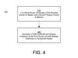
- a first virtual router 341that spans two or more physical routing devices (e.g., the devices 310 and 32 ) is defined.
- One of the physical routing devicesis designated as master, and the other physical routing device(s) are designated as backups.
- the mastere.g., the device 310
- the mastercan include multiple interfaces (e.g., ports), where some of the interfaces (e.g., the interface 311 ) are associated with the first virtual router, and other interfaces (e.g., the interface 312 ) are associated with a second virtual router 342 that also spans the physical routing devices spanned by the first virtual router.
- the interfaces on the backupscan be similarly configured.
- a VRID-Mis associated with multiple interfaces (e.g., the interfaces 311 and 312 ) on the master, the VRID-M is associated with multiple interfaces (e.g., the interfaces 321 and 322 ) on a first backup, and so on.
- Each of the interfaces on the master, and each of the interfaces on the backupsmay also be associated with one or more VRIDs. That is, there may be multiple VRIDs per interface, such that any interface may be associated with multiple virtual routers.
- multiple sets of interface parametersare specified for each VRID-M. For example, a first set of interface parameters are specified for one interface associated with the VRID-M, a different second set of interface parameters are specified for a second interface associated with the VRID-M, and so on.
- the virtual router 341fails over from the current master to a backup
- the virtual router 342also fails over from the device 310 to the device 320 .
- traffic initially routed through, for example, the interfaces 311 and 312is instead routed through corresponding interfaces (e.g., the interfaces 321 and 322 ) on the backup device.
- traffic that is received into a physical routing deviceis also sent out from that routing device. Packets are not dropped, nor do packets received at one physical routing device have to be routed to another routing device in order to be forwarded to their destination.
Landscapes
- Engineering & Computer Science (AREA)
- Computer Networks & Wireless Communication (AREA)
- Signal Processing (AREA)
- Data Exchanges In Wide-Area Networks (AREA)
Abstract
Description
| Backup | ||||
| Case | ||||
| 1 | ||||
| VRID-M = 3 | Device 320 | |||
| VRID-M = 3 | Device 320 | |||
| Backup | ||||
| Case | ||||
| 1 | ||||
| VRID = 1 | Device 320 | |||
| VRID = 2 | Device 320 | |||
| VRID = 1 | Device 320 | |||
| VRID = 2 | Device 320 | |||
| Master | Backup | |||
| Case 1 (Failover) | ||||
| VRID-M = 3 | Device 320 | |||
| Case 1 (Failover) | ||||
| VRID = 1 | Device 320 | |||
| VRID = 2 | Device 320 | |||
| Case 2 (Failover) | ||||
| VRID-M = 3 | Device 320 | |||
| Case 2 (Failover) | ||||
| VRID = 1 | Device 320 | |||
| VRID = 2 | Device 320 | |||
| Master | Backup | |||
| VRID = 1 | Device 320 | |||
| VRID = 2 | Device 320 | |||
| VRID = 1 | Device 320 | |||
| VRID = 2 | Device 320 | |||
Claims (20)
Priority Applications (1)
| Application Number | Priority Date | Filing Date | Title |
|---|---|---|---|
| US12/130,721US8014409B1 (en) | 2007-05-30 | 2008-05-30 | Virtual router identifier that spans multiple interfaces in a routing device |
Applications Claiming Priority (2)
| Application Number | Priority Date | Filing Date | Title |
|---|---|---|---|
| US93240807P | 2007-05-30 | 2007-05-30 | |
| US12/130,721US8014409B1 (en) | 2007-05-30 | 2008-05-30 | Virtual router identifier that spans multiple interfaces in a routing device |
Publications (1)
| Publication Number | Publication Date |
|---|---|
| US8014409B1true US8014409B1 (en) | 2011-09-06 |
Family
ID=43880483
Family Applications (3)
| Application Number | Title | Priority Date | Filing Date |
|---|---|---|---|
| US12/130,721Active2029-03-28US8014409B1 (en) | 2007-05-30 | 2008-05-30 | Virtual router identifier that spans multiple interfaces in a routing device |
| US12/130,677Expired - Fee RelatedUS7933198B1 (en) | 2007-05-30 | 2008-05-30 | Virtual router failover dampening |
| US13/076,222Expired - Fee RelatedUS8339943B2 (en) | 2007-05-30 | 2011-03-30 | Virtual router failover dampening |
Family Applications After (2)
| Application Number | Title | Priority Date | Filing Date |
|---|---|---|---|
| US12/130,677Expired - Fee RelatedUS7933198B1 (en) | 2007-05-30 | 2008-05-30 | Virtual router failover dampening |
| US13/076,222Expired - Fee RelatedUS8339943B2 (en) | 2007-05-30 | 2011-03-30 | Virtual router failover dampening |
Country Status (1)
| Country | Link |
|---|---|
| US (3) | US8014409B1 (en) |
Cited By (7)
| Publication number | Priority date | Publication date | Assignee | Title |
|---|---|---|---|---|
| US20100098082A1 (en)* | 2008-10-16 | 2010-04-22 | Rangaprasad Sampath | Method for application broadcast forwarding for routers running redundancy protocols |
| US20100274894A1 (en)* | 2009-04-22 | 2010-10-28 | Hewlett Packard Development Company Lp | Router Method And System |
| US20110085560A1 (en)* | 2009-10-12 | 2011-04-14 | Dell Products L.P. | System and Method for Implementing a Virtual Switch |
| US20110134802A1 (en)* | 2009-12-09 | 2011-06-09 | Cisco Technology, Inc. | Determining A Routing Tree For Networks With Different Routing Protocols |
| US10382330B2 (en)* | 2013-06-21 | 2019-08-13 | C.R.D. Centro Ricerche Ducati Trento S.R.L. | System for the routing of data to computer networks |
| US10382329B1 (en)* | 2016-09-30 | 2019-08-13 | Juniper Networks, Inc. | Source MAC access controls in a virtual redundant router protocol environment |
| US12021925B1 (en)* | 2017-08-04 | 2024-06-25 | 128 Technology, Inc. | Network neighborhoods for establishing communication relationships between communication interfaces in an administrative domain |
Families Citing this family (21)
| Publication number | Priority date | Publication date | Assignee | Title |
|---|---|---|---|---|
| US8014409B1 (en)* | 2007-05-30 | 2011-09-06 | Foundry Networks, Llc | Virtual router identifier that spans multiple interfaces in a routing device |
| US8493846B2 (en)* | 2009-09-30 | 2013-07-23 | At&T Intellectual Property I, L.P. | Robust multicast broadcasting |
| CN102170398B (en)* | 2011-05-09 | 2016-09-28 | 中兴通讯股份有限公司 | The reverse method of external time port and device |
| US9172603B2 (en) | 2011-11-15 | 2015-10-27 | Nicira, Inc. | WAN optimizer for logical networks |
| JP6217190B2 (en)* | 2013-07-05 | 2017-10-25 | 富士通株式会社 | Packet relay device, packet relay system, and packet relay method |
| US9455901B2 (en) | 2013-10-04 | 2016-09-27 | Nicira, Inc. | Managing software and hardware forwarding elements to define virtual networks |
| US9942058B2 (en) | 2015-04-17 | 2018-04-10 | Nicira, Inc. | Managing tunnel endpoints for facilitating creation of logical networks |
| US9967182B2 (en) | 2015-07-31 | 2018-05-08 | Nicira, Inc. | Enabling hardware switches to perform logical routing functionalities |
| US10091056B1 (en) | 2015-08-06 | 2018-10-02 | Amazon Technologies, Inc. | Distribution of modular router configuration |
| US10313186B2 (en) | 2015-08-31 | 2019-06-04 | Nicira, Inc. | Scalable controller for hardware VTEPS |
| US10419282B1 (en)* | 2015-09-24 | 2019-09-17 | Amazon Technologies, Inc. | Self-configuring network devices |
| US10263828B2 (en) | 2015-09-30 | 2019-04-16 | Nicira, Inc. | Preventing concurrent distribution of network data to a hardware switch by multiple controllers |
| US9948577B2 (en) | 2015-09-30 | 2018-04-17 | Nicira, Inc. | IP aliases in logical networks with hardware switches |
| US10230576B2 (en) | 2015-09-30 | 2019-03-12 | Nicira, Inc. | Managing administrative statuses of hardware VTEPs |
| US9979593B2 (en) | 2015-09-30 | 2018-05-22 | Nicira, Inc. | Logical L3 processing for L2 hardware switches |
| US10250553B2 (en) | 2015-11-03 | 2019-04-02 | Nicira, Inc. | ARP offloading for managed hardware forwarding elements |
| US9998375B2 (en) | 2015-12-15 | 2018-06-12 | Nicira, Inc. | Transactional controls for supplying control plane data to managed hardware forwarding elements |
| US9992112B2 (en) | 2015-12-15 | 2018-06-05 | Nicira, Inc. | Transactional controls for supplying control plane data to managed hardware forwarding elements |
| US10320898B2 (en)* | 2016-06-06 | 2019-06-11 | Verizon Patent And Licensing Inc. | Automated multi-network failover for data centers |
| US10200343B2 (en) | 2016-06-29 | 2019-02-05 | Nicira, Inc. | Implementing logical network security on a hardware switch |
| US10817329B1 (en)* | 2020-02-07 | 2020-10-27 | Coupang Corp. | Systems and methods for centralization and diagnostics for live virtual server performance data |
Citations (7)
| Publication number | Priority date | Publication date | Assignee | Title |
|---|---|---|---|---|
| US20020184387A1 (en)* | 2001-05-31 | 2002-12-05 | The Furukawa Electric Co., Ltd. | Method for connecting between networks, virtual router, and system for connecting between networks by using this virtual router |
| US20030037165A1 (en)* | 2001-07-06 | 2003-02-20 | Daisuke Shinomiya | Dynamic load sharing system using a virtual router |
| US20040085965A1 (en)* | 2002-10-31 | 2004-05-06 | Shivi Fotedar | Redundant router network |
| US20040165604A1 (en) | 2003-02-20 | 2004-08-26 | Jong-Sang Oh | Distributed router with ping-pong preventing function and ping-pong preventing method using the same |
| US20040240455A1 (en)* | 2002-07-20 | 2004-12-02 | Naiming Shen | Method and apparatus for routing and forwarding between virtual routers within a single network element |
| US20050249113A1 (en) | 2003-02-14 | 2005-11-10 | Hirokazu Kobayashi | Network connection apparatus and network connection switching method |
| US20070133472A1 (en) | 2005-12-10 | 2007-06-14 | Won-Ik Kim | Method of vertical handoff |
Family Cites Families (2)
| Publication number | Priority date | Publication date | Assignee | Title |
|---|---|---|---|---|
| US7189777B2 (en)* | 2003-06-09 | 2007-03-13 | Eastman Chemical Company | Compositions and method for improving reheat rate of PET using activated carbon |
| US8014409B1 (en)* | 2007-05-30 | 2011-09-06 | Foundry Networks, Llc | Virtual router identifier that spans multiple interfaces in a routing device |
- 2008
- 2008-05-30USUS12/130,721patent/US8014409B1/enactiveActive
- 2008-05-30USUS12/130,677patent/US7933198B1/ennot_activeExpired - Fee Related
- 2011
- 2011-03-30USUS13/076,222patent/US8339943B2/ennot_activeExpired - Fee Related
Patent Citations (7)
| Publication number | Priority date | Publication date | Assignee | Title |
|---|---|---|---|---|
| US20020184387A1 (en)* | 2001-05-31 | 2002-12-05 | The Furukawa Electric Co., Ltd. | Method for connecting between networks, virtual router, and system for connecting between networks by using this virtual router |
| US20030037165A1 (en)* | 2001-07-06 | 2003-02-20 | Daisuke Shinomiya | Dynamic load sharing system using a virtual router |
| US20040240455A1 (en)* | 2002-07-20 | 2004-12-02 | Naiming Shen | Method and apparatus for routing and forwarding between virtual routers within a single network element |
| US20040085965A1 (en)* | 2002-10-31 | 2004-05-06 | Shivi Fotedar | Redundant router network |
| US20050249113A1 (en) | 2003-02-14 | 2005-11-10 | Hirokazu Kobayashi | Network connection apparatus and network connection switching method |
| US20040165604A1 (en) | 2003-02-20 | 2004-08-26 | Jong-Sang Oh | Distributed router with ping-pong preventing function and ping-pong preventing method using the same |
| US20070133472A1 (en) | 2005-12-10 | 2007-06-14 | Won-Ik Kim | Method of vertical handoff |
Non-Patent Citations (4)
| Title |
|---|
| "BGP Route Flap Damping" Villamizar, et al. Standards Track Nov. 1998, 1-37. |
| "Virtual Router Redundancy Protocol (VRRP)" Ed. R. Hinden Standards Track Apr. 2004, 1-27. |
| Cisco IOS Software Releases 12.0 S "IP Event Dampening" http://www.cisco.com/en/US/docs/ios/12-0s/feature/guide/s-ipevdp.html. |
| Serverlron TraffficWorks L4-7 Configuration Guide Release 10.0.00a Release Date May 10, 2007, Publication Date May 10, 2007. Foundry Networks pp. 8-29-8-44. |
Cited By (9)
| Publication number | Priority date | Publication date | Assignee | Title |
|---|---|---|---|---|
| US20100098082A1 (en)* | 2008-10-16 | 2010-04-22 | Rangaprasad Sampath | Method for application broadcast forwarding for routers running redundancy protocols |
| US8891358B2 (en)* | 2008-10-16 | 2014-11-18 | Hewlett-Packard Development Company, L.P. | Method for application broadcast forwarding for routers running redundancy protocols |
| US20100274894A1 (en)* | 2009-04-22 | 2010-10-28 | Hewlett Packard Development Company Lp | Router Method And System |
| US9397979B2 (en)* | 2009-04-22 | 2016-07-19 | Hewlett Packard Enterprise Development Lp | Router method and system |
| US20110085560A1 (en)* | 2009-10-12 | 2011-04-14 | Dell Products L.P. | System and Method for Implementing a Virtual Switch |
| US20110134802A1 (en)* | 2009-12-09 | 2011-06-09 | Cisco Technology, Inc. | Determining A Routing Tree For Networks With Different Routing Protocols |
| US10382330B2 (en)* | 2013-06-21 | 2019-08-13 | C.R.D. Centro Ricerche Ducati Trento S.R.L. | System for the routing of data to computer networks |
| US10382329B1 (en)* | 2016-09-30 | 2019-08-13 | Juniper Networks, Inc. | Source MAC access controls in a virtual redundant router protocol environment |
| US12021925B1 (en)* | 2017-08-04 | 2024-06-25 | 128 Technology, Inc. | Network neighborhoods for establishing communication relationships between communication interfaces in an administrative domain |
Also Published As
| Publication number | Publication date |
|---|---|
| US20110176410A1 (en) | 2011-07-21 |
| US7933198B1 (en) | 2011-04-26 |
| US8339943B2 (en) | 2012-12-25 |
Similar Documents
| Publication | Publication Date | Title |
|---|---|---|
| US8014409B1 (en) | Virtual router identifier that spans multiple interfaces in a routing device | |
| US10693765B2 (en) | Failure protection for traffic-engineered bit indexed explicit replication | |
| CN101601232B (en) | Triple-tier anycast addressing | |
| EP3691205B1 (en) | Traffic forwarding method and traffic forwarding apparatus | |
| CN108574616B (en) | Method, equipment and system for processing route | |
| US9887917B2 (en) | Port extender | |
| CN101404619B (en) | Method for implementing server load balancing and a three-layer switchboard | |
| US7123615B2 (en) | Stacked network routers | |
| US20040008694A1 (en) | Method for implementing router interface backup with virtual router redundancy protocol | |
| EP4020904B1 (en) | Packet transmission method, device, and system | |
| US20120020364A1 (en) | Border gateway protocol inbound policy optimization | |
| CN113381929B (en) | Route processing method, gateway equipment and computer storage medium | |
| US8446818B2 (en) | Routed split multi-link trunking resiliency for wireless local area network split-plane environments | |
| EP1345356B1 (en) | Topology discovery process and mechanism for a network of managed devices | |
| US20200136958A1 (en) | System and method for efficient route update in an evpn network | |
| CN102938732B (en) | A kind of method and device improving double-tunnel reliability | |
| US10917378B1 (en) | Facilitating communication between network devices of a virtual router redundancy protocol (VRRP) group | |
| CN106209634B (en) | Learning method and device of address mapping relation | |
| US8125995B2 (en) | Method and system for implementing dynamic signaling routing | |
| CN113765799A (en) | Method for sending and receiving container messages, storage medium, and container communication system | |
| US12126598B2 (en) | Managing exchanges between edge gateways in a cloud environment to support a private network connection | |
| WO2020181733A1 (en) | Vpc-based multi-data center intercommunication method and related device | |
| US20060098665A1 (en) | Systems and methods for communicating with bi-nodal network elements | |
| JPH1032597A (en) | Inter-lan connection device | |
| US20250260645A1 (en) | Providing dual-homed, active-active devices on network fabrics |
Legal Events
| Date | Code | Title | Description |
|---|---|---|---|
| AS | Assignment | Owner name:FOUNDRY NETWORKS, INC., CALIFORNIA Free format text:ASSIGNMENT OF ASSIGNORS INTEREST;ASSIGNOR:XIAOHONG PAN;REEL/FRAME:021274/0326 Effective date:20080530 | |
| AS | Assignment | Owner name:BANK OF AMERICA, N.A. AS ADMINISTRATIVE AGENT, CAL Free format text:SECURITY AGREEMENT;ASSIGNORS:BROCADE COMMUNICATIONS SYSTEMS, INC.;FOUNDRY NETWORKS, INC.;INRANGE TECHNOLOGIES CORPORATION;AND OTHERS;REEL/FRAME:022012/0204 Effective date:20081218 | |
| AS | Assignment | Owner name:WELLS FARGO BANK, NATIONAL ASSOCIATION, AS COLLATE Free format text:SECURITY AGREEMENT;ASSIGNORS:BROCADE COMMUNICATIONS SYSTEMS, INC.;FOUNDRY NETWORKS, LLC;INRANGE TECHNOLOGIES CORPORATION;AND OTHERS;REEL/FRAME:023814/0587 Effective date:20100120 | |
| AS | Assignment | Owner name:FOUNDRY NETWORKS, LLC, CALIFORNIA Free format text:CHANGE OF NAME;ASSIGNOR:FOUNDRY NETWORKS, INC.;REEL/FRAME:024733/0739 Effective date:20090511 | |
| STCF | Information on status: patent grant | Free format text:PATENTED CASE | |
| AS | Assignment | Owner name:BANK OF AMERICA, N.A., AS ADMINISTRATIVE AGENT, CA Free format text:SUPPLEMENTAL PATENT SECURITY AGREEMENT;ASSIGNORS:BROCADE COMMUNICATIONS SYSTEMS, INC.;FOUNDRY NETWORKS, LLC;MCDATA CORPORATION;REEL/FRAME:026938/0922 Effective date:20110916 | |
| AS | Assignment | Owner name:WELLS FARGO BANK, NATIONAL ASSOCIATION, AS COLLATE Free format text:SUPPLEMENTAL PATENT SECURITY AGREEMENT;ASSIGNORS:BROCADE COMMUNICATIONS SYSTEMS, INC.;FOUNDRY NETWORKS, LLC;INRANGE TECHNOLOGIES CORPORATION;AND OTHERS;REEL/FRAME:026971/0042 Effective date:20110916 | |
| AS | Assignment | Owner name:FOUNDRY NETWORKS, LLC, CALIFORNIA Free format text:RELEASE BY SECURED PARTY;ASSIGNOR:BANK OF AMERICA, N.A., AS ADMINISTRATIVE AGENT;REEL/FRAME:034784/0609 Effective date:20150114 Owner name:BROCADE COMMUNICATIONS SYSTEMS, INC., CALIFORNIA Free format text:RELEASE BY SECURED PARTY;ASSIGNOR:BANK OF AMERICA, N.A., AS ADMINISTRATIVE AGENT;REEL/FRAME:034784/0609 Effective date:20150114 Owner name:INRANGE TECHNOLOGIES CORPORATION, CALIFORNIA Free format text:RELEASE BY SECURED PARTY;ASSIGNOR:BANK OF AMERICA, N.A., AS ADMINISTRATIVE AGENT;REEL/FRAME:034792/0540 Effective date:20140114 Owner name:BROCADE COMMUNICATIONS SYSTEMS, INC., CALIFORNIA Free format text:RELEASE BY SECURED PARTY;ASSIGNOR:BANK OF AMERICA, N.A., AS ADMINISTRATIVE AGENT;REEL/FRAME:034792/0540 Effective date:20140114 Owner name:FOUNDRY NETWORKS, LLC, CALIFORNIA Free format text:RELEASE BY SECURED PARTY;ASSIGNOR:BANK OF AMERICA, N.A., AS ADMINISTRATIVE AGENT;REEL/FRAME:034792/0540 Effective date:20140114 | |
| AS | Assignment | Owner name:FOUNDRY NETWORKS, LLC, CALIFORNIA Free format text:RELEASE BY SECURED PARTY;ASSIGNOR:WELLS FARGO BANK, NATIONAL ASSOCIATION, AS COLLATERAL AGENT;REEL/FRAME:034804/0793 Effective date:20150114 Owner name:BROCADE COMMUNICATIONS SYSTEMS, INC., CALIFORNIA Free format text:RELEASE BY SECURED PARTY;ASSIGNOR:WELLS FARGO BANK, NATIONAL ASSOCIATION, AS COLLATERAL AGENT;REEL/FRAME:034804/0793 Effective date:20150114 | |
| REMI | Maintenance fee reminder mailed | ||
| FPAY | Fee payment | Year of fee payment:4 | |
| SULP | Surcharge for late payment | ||
| AS | Assignment | Owner name:AVAGO TECHNOLOGIES INTERNATIONAL SALES PTE. LIMITED, SINGAPORE Free format text:ASSIGNMENT OF ASSIGNORS INTEREST;ASSIGNOR:BROCADE COMMUNICATIONS SYSTEMS LLC;REEL/FRAME:047270/0247 Effective date:20180905 Owner name:AVAGO TECHNOLOGIES INTERNATIONAL SALES PTE. LIMITE Free format text:ASSIGNMENT OF ASSIGNORS INTEREST;ASSIGNOR:BROCADE COMMUNICATIONS SYSTEMS LLC;REEL/FRAME:047270/0247 Effective date:20180905 | |
| MAFP | Maintenance fee payment | Free format text:PAYMENT OF MAINTENANCE FEE, 8TH YEAR, LARGE ENTITY (ORIGINAL EVENT CODE: M1552); ENTITY STATUS OF PATENT OWNER: LARGE ENTITY Year of fee payment:8 | |
| MAFP | Maintenance fee payment | Free format text:PAYMENT OF MAINTENANCE FEE, 12TH YEAR, LARGE ENTITY (ORIGINAL EVENT CODE: M1553); ENTITY STATUS OF PATENT OWNER: LARGE ENTITY Year of fee payment:12 |