US8013613B2 - Voltage indicator test mechanism - Google Patents
Voltage indicator test mechanismDownload PDFInfo
- Publication number
- US8013613B2 US8013613B2US11/608,087US60808706AUS8013613B2US 8013613 B2US8013613 B2US 8013613B2US 60808706 AUS60808706 AUS 60808706AUS 8013613 B2US8013613 B2US 8013613B2
- Authority
- US
- United States
- Prior art keywords
- electrical safety
- current
- safety monitor
- test current
- generating
- Prior art date
- Legal status (The legal status is an assumption and is not a legal conclusion. Google has not performed a legal analysis and makes no representation as to the accuracy of the status listed.)
- Active, expires
Links
- 238000012360testing methodMethods0.000titleclaimsabstractdescription49
- 238000012544monitoring processMethods0.000claimsabstractdescription25
- 230000007704transitionEffects0.000claimsabstractdescription16
- 230000001939inductive effectEffects0.000claimsabstractdescription9
- 239000011263electroactive materialSubstances0.000claimsabstractdescription7
- 238000000034methodMethods0.000claimsdescription12
- 230000004913activationEffects0.000claimsdescription6
- 230000004044responseEffects0.000claimsdescription6
- 230000006872improvementEffects0.000claimsdescription4
- 230000002463transducing effectEffects0.000claimsdescription3
- 230000008901benefitEffects0.000description6
- 238000012806monitoring deviceMethods0.000description5
- 238000013461designMethods0.000description4
- 238000012423maintenanceMethods0.000description4
- 239000000463materialSubstances0.000description3
- 231100001261hazardousToxicity0.000description2
- 238000002347injectionMethods0.000description2
- 239000007924injectionSubstances0.000description2
- 230000001681protective effectEffects0.000description2
- 230000000903blocking effectEffects0.000description1
- 239000003990capacitorSubstances0.000description1
- 238000004891communicationMethods0.000description1
- 238000010276constructionMethods0.000description1
- 238000010586diagramMethods0.000description1
- 230000006698inductionEffects0.000description1
- 238000009434installationMethods0.000description1
- 238000002955isolationMethods0.000description1
- 239000007787solidSubstances0.000description1
- 230000000007visual effectEffects0.000description1
Images


Classifications
- G—PHYSICS
- G01—MEASURING; TESTING
- G01R—MEASURING ELECTRIC VARIABLES; MEASURING MAGNETIC VARIABLES
- G01R19/00—Arrangements for measuring currents or voltages or for indicating presence or sign thereof
- G01R19/145—Indicating the presence of current or voltage
- G01R19/155—Indicating the presence of voltage
- G—PHYSICS
- G01—MEASURING; TESTING
- G01R—MEASURING ELECTRIC VARIABLES; MEASURING MAGNETIC VARIABLES
- G01R35/00—Testing or calibrating of apparatus covered by the other groups of this subclass
Definitions
- a voltage indicatoris generally a low cost device that pre-verifies electrical isolation before maintenance personnel open a control panel and risk exposure to hazardous voltages. Typically mounted to the panel exterior and hardwired into the load side of the main disconnect, this device provides electrical maintenance with an additional safety value. Easy to apply, low cost, quick installation, and inherent reliability makes a voltage indicator a very effective electrical safety device.
- Creating and insuring an electrically safe work conditionis critical for electricians performing maintenance on de-energized systems.
- the presence of voltageis the only determining factor if an electrical accident or an arc flash can possibly occur—No voltage, No accident, No arc flash.
- “Voltage or no voltage”is also the basis of the NFPA 70E's (National Fire Protection Association Standard's for Electrical Safety Requirements for Employee Workplaces) two primary themes: a) establishing an electrically safe work condition, and b) achieving safety while working on energized systems.
- a voltage warning indicatoris like a ‘hard wired voltmeter’ with the advantage that it needs no power supply or batteries because it is powered from the same ‘voltage’ that it indicates.
- a voltage indicatoris an additional safety measure between maintenance personnel and hazardous voltage.
- Clarktransitions well from a live state to a dead state. However, once it is in the dead state it cannot provide a positive indication of zero energy. In other words, if the user disconnects the power from the electrical system, one cannot discern between failure and an off state of the voltage indicator.
- a test feature on the voltage indicatorallows the electrician a means to inject a test current into the circuit, which temporarily re-energizes the circuit to insure it is still fully functional. This feature allows the device to transition from dead to live thereby meeting the requirements of the “Live-Dead-Live” procedure.
- the inventorhas recognized the problem of needing to discern between a failure state and an off state.
- the present inventionprovides for a test feature that allows an electrician or other to see a device transition from non-energized (Dead) to energized (Live).
- an electrical safety monitorincludes line inputs for an L 1 , an L 2 , an L 3 , and a GND three-phase connections, a line monitoring circuit having a plurality of light indicators and configured to produce light if voltage exists between any two of the line inputs to thereby indicate presence of voltage to a user, and a current generating circuit electrically connected to the line monitoring circuit and adapted to generate a test current to the line inputs to transition the device from dead to live, thereby allowing the user to discern between a failure state of the line monitoring circuit and an off state of the line monitoring circuit.
- the current generating circuitmay include a magnet and the current generating circuit may be adapted to induce the test current in response to movement of the magnet, either linear movement or rotational movement.
- the current generating circuitmay include an electroactive material adapted for transducing mechanical movement into the test current, such as a piezoelectric element.
- the current generating circuitmay include a stored charge circuit adapted for injecting the test current in response to activation of a switch.
- the current generating circuitmay include a photocell adapted for generating the test current.
- the current generating circuitmay include a spring loaded crank adapted for generating the test current.
- an improvement to an electrical safety monitorhaving a line monitoring circuit for monitoring L 1 , L 2 , L 3 , and GND three-phase line connections and a plurality of indicators for communicating presence of voltage between any of the line connections.
- the improvementincludes a current inducing circuit electrically connected to the line monitoring circuit and adapted for generating a test current upon activation by a user to transition the line monitoring circuit from dead to live thereby allowing the user to discern between a failure state of the line monitoring circuit and an off state for the line monitoring circuit.
- a method for providing electrical safety monitoringincludes providing an electrical safety monitor having a plurality of solid-state light emitting diodes configured to indicate presence of voltage and generating a test current to transition the electrical safety monitor from a dead state to a live state to thereby allow a user to discern between a failure state and an off state.
- FIG. 1illustrates one embodiment of the present invention.
- FIG. 2illustrates one embodiment of the present invention where magnetic induction is used to inject a test current.
- FIG. 3illustrates one embodiment of the present invention where stored charge is used to inject a test current.
- FIG. 4illustrates one embodiment of the present invention where a photocell circuit is used to store and inject a test current.
- FIG. 5illustrates one embodiment of the present invention where electroactive or pressure sensitive material is used to inject a test current.
- FIG. 6illustrates one embodiment of the present invention where a magnet is used to induce a current to inject into a line monitoring device.
- FIG. 7illustrates one embodiment of methodology of the present invention.
- the present inventionprovides for injecting a test current into a circuit so that an electrician can see the device transition from dead to live. Observing this transition allows an electrician or other operator to know that the device is in the off state. Without seeing the transition, the operator would not necessarily know whether the device was truly in an off state or whether the device was in a dead state.
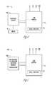
- FIG. 1provides a block diagram of one embodiment of the present invention.
- a device 10is shown.
- the device 10includes a line monitor device 12 having indicators 16 such as light emitting diodes (LEDs) or lamps.
- a current generating circuit 18is in electrical communication with the line monitoring device 12 .
- the current generating circuit 18may include a magnet, an electroactive material such as a piezoelectric element, a photocell, a circuit which stores energy, a spring loaded crank, or other element or configuration which is adapted for injecting a test current into the line monitoring device 12 .
- the injection of a test current into line monitoring device 12allows an electrician or other operator to observe the transition from a dead state to a live state.
- FIG. 2illustrates one embodiment where the electrical safety monitor 10 A includes a magnetic inducing circuit 18 A. Rotational or linear movement may be applied to a magnet in order to induce a current which is applied to the line monitor 12 .
- the line monitor 12includes a visual indicator 16 which may, for example, include multiple solid state light emitting diodes.
- FIG. 3illustrates one embodiment where the electrical safety monitor 10 B includes a stored charge circuit 18 B.
- a switch 20such as, but not limited to, a pushbutton may be used to inject a test current from the stored charge circuit to the line monitor 12 .
- the stored charge circuitmay, for example, include one or more capacitors (not shown) to store charge.
- FIG. 4illustrates one embodiment where the electrical safety monitor 10 C includes a photocell circuit 18 and a switch electrically connected to the photocell circuit 18 C.
- the photocell circuit 18 Cis used to generate and store energy to provide a test current which, when the switch 20 is pressed, will be injected into the line monitor 12 .
- FIG. 5illustrates one embodiment where the electrical safety monitor 10 F includes an electroactive or pressure sensitive material 18 D.
- the electroactive or pressure sensitive material 18 Dis deformed to generate a test current which is injected into the line monitor 12 .
- FIG. 6illustrates one embodiment where the line monitor 12 used is based on that disclosed in U.S. Pat. No. 6,703,938 to Clarke, herein incorporated by reference in its entirety.
- the electrical safety monitor 10 Auses a magnetic inducing circuit 18 A to induce a test current into the line monitor 12 .
- Line inputsare shown for lines L 1 , L 2 , L 3 , and the ground potential GND, each of which are connected to a power limiting resistor, R 1 , R 2 , R 3 , and R 4 , respectively.
- the line inputsare associated with three-phase power connections.
- the safety monitoring devicesmonitors the lines L 1 , L 2 , L 3 , and GND for presence of electrical energy.
- Each LED D 1 , D 2 , D 3 , D 4 , D 5 , D 6 , D 7 , D 8produces light to indicate current flow in its path.
- R 5 , R 6 , R 7 , R 8 , R 9 , R 10 , R 11 , and R 12associated with the LEDs.
- Zener diodes Z 1 , Z 2are used for limiting voltage.
- Zener diode Z 3also serves as a protective element to limit voltage over the capacitances C 1 , C 2 , C 3 , C 4 , C 5 , C 6 , C 7 , C 8 .
- Diodes D 9 , D 10 , D 11 , D 12 , D 17 , D 18 , D 19are blocking diodes also used as protective elements.
- Diodes D 13 , D 14 , D 15 , D 16 , D 21 , D 22 , D 23 , D 24are used as rectifying diodes.
- Discharge or flasher circuits F 1 , F 2are used so that stored energy in the capacitances is discharged through the corresponding light emitting diodes.
- Indicators 16 Aare configured to draw current from positively charged lines and to produce light indicative of positive voltage potential between these lines and other lines.
- Indicators 16 Bare configured to draw current from negatively charged lines and to produce light indicative of negative voltage potential between these lines and other lines.
- the line monitor 12can be used to identify the presence of AC or DC voltages across any of the line inputs and grounds.
- the design of the circuit of the line monitor 12also includes some redundancy. However, consider the case where there are no indicator lights present. The absence of indicator lights may mean that there are no voltages present and thus a safe state exists. Unfortunately, the absence of indicator lights could also mean that the line monitor 12 has simply failed and there is voltage present.
- the magnetic current inducing circuit 18 Aallows a test current to be introduced, which once induced will be detected by the circuit 12 and an appropriate indicator lights will be temporarily lit if the circuit 12 is functioning properly. If the circuit 12 has failed, then no indicator light will be lit and the operator will know that the circuit 12 has failed and that there may be voltage present. In other words, the current inducing circuit 18 allows an electrician or other operator to watch the transition of the circuit from live to dead.
- the addition of the magnetic current inducing circuit 18 Aallows a test current to be induced by movement of a magnet 24 with respect to coils 26 and 28 .
- the movementmay be linear movement as indicated by arrow 30 or rotational movement as indicated by arrow 32 .
- the coils 26 , 28are electrically connected through test current injection circuit 33 thus resulting in activation of corresponding LEDs.
- the estimated current per phaseis between approximately 100 and 300 microamps. Of course, the current can vary based on the circuit design and components used.
- FIG. 3illustrates one embodiment of the methodology of the present invention.
- an electrical safety monitoris provided in step 50 .
- a test currentis generated to transition the electrical safety monitor from a dead state to a live state so that an electrician or other operator can distinguish between a dead state and a failure state of the electrical safety monitor.
- the present inventioncontemplates numerous variations in the construction of the present invention. There could, for example, be a single generator with multiplexed outputs or separate generators.
- the circuit of the present inventioncan be incorporated into different types of devices, including devices using different circuits and having different types of housing. These and other variations and alternatives in design and methodology are within the spirit and scope of the claimed invention.
Landscapes
- Physics & Mathematics (AREA)
- General Physics & Mathematics (AREA)
- Measurement Of Current Or Voltage (AREA)
Abstract
Description
Claims (22)
Priority Applications (1)
| Application Number | Priority Date | Filing Date | Title |
|---|---|---|---|
| US11/608,087US8013613B2 (en) | 2005-12-08 | 2006-12-07 | Voltage indicator test mechanism |
Applications Claiming Priority (2)
| Application Number | Priority Date | Filing Date | Title |
|---|---|---|---|
| US74846005P | 2005-12-08 | 2005-12-08 | |
| US11/608,087US8013613B2 (en) | 2005-12-08 | 2006-12-07 | Voltage indicator test mechanism |
Publications (2)
| Publication Number | Publication Date |
|---|---|
| US20070132458A1 US20070132458A1 (en) | 2007-06-14 |
| US8013613B2true US8013613B2 (en) | 2011-09-06 |
Family
ID=38138655
Family Applications (1)
| Application Number | Title | Priority Date | Filing Date |
|---|---|---|---|
| US11/608,087Active2027-12-20US8013613B2 (en) | 2005-12-08 | 2006-12-07 | Voltage indicator test mechanism |
Country Status (1)
| Country | Link |
|---|---|
| US (1) | US8013613B2 (en) |
Cited By (12)
| Publication number | Priority date | Publication date | Assignee | Title |
|---|---|---|---|---|
| US9024615B2 (en) | 2010-10-25 | 2015-05-05 | Grace Engineered Products, Inc. | Non-contact voltage detector |
| CN105652141A (en)* | 2016-03-14 | 2016-06-08 | 湖南工业大学 | Self-diagnosis system for locomotive top ascending high-voltage alarm |
| USD813064S1 (en) | 2016-09-19 | 2018-03-20 | Panduit Corp. | Voltage indicator lighting arrangement |
| US9921260B2 (en) | 2013-12-20 | 2018-03-20 | Panduit Corp. | Voltage indicator with continuity check |
| US10418216B2 (en)* | 2017-04-28 | 2019-09-17 | Intermountain Electronics, Inc. | Phase operation indicator |
| US10901013B2 (en) | 2018-06-25 | 2021-01-26 | Rolls-Royce North American Technologies, Inc. | Apparatus and method for detecting the absence of voltage |
| US11215646B2 (en) | 2019-04-22 | 2022-01-04 | Panduit Corp. | Absence of voltage detection device |
| US20220091192A1 (en)* | 2020-09-24 | 2022-03-24 | Grace Technologies, Inc. | Test point device |
| US11378593B2 (en) | 2016-09-19 | 2022-07-05 | Panduit Corp. | Voltage indicator display module with removable battery shuttle |
| US20220254208A1 (en)* | 2021-02-08 | 2022-08-11 | Panduit Corp. | System for Controlling Access to an Enclosure |
| AU2021202725B2 (en)* | 2014-09-05 | 2023-05-18 | Panduit Corp. | Method and device for detecting the absence of voltage |
| US11885837B2 (en) | 2020-09-17 | 2024-01-30 | Automatic Timing & Controls, Inc. | Ultra-low leakage test verification circuit |
Families Citing this family (35)
| Publication number | Priority date | Publication date | Assignee | Title |
|---|---|---|---|---|
| US8094034B2 (en) | 2007-09-18 | 2012-01-10 | Georgia Tech Research Corporation | Detecting actuation of electrical devices using electrical noise over a power line |
| MX2011002459A (en) | 2008-09-19 | 2011-06-24 | Schweitzer Engineering Lab Inc | Electro-optical radiation collector for arc flash detection. |
| CA2736009C (en)* | 2008-09-19 | 2013-07-16 | Schweitzer Engineering Laboratories, Inc. | Arc flash protection with self-test |
| US8451572B2 (en)* | 2008-09-19 | 2013-05-28 | Schweitzer Engineering Laboratories Inc | Protective device with metering and oscillography |
| BRPI0918933A2 (en)* | 2008-09-19 | 2017-08-01 | Schweitzer Engineering Lab Inc | intelligent electronic device (ied), and method for detecting an arc event in a power system |
| BRPI0918900A2 (en)* | 2008-09-19 | 2017-08-01 | Schweitzer Engineering Lab Inc | apparatus for validating an electrical arc detection unit (afdu), computer readable storage medium, and method for determining the configuration of an electrical arc detection unit (afdu) |
| US8261158B2 (en) | 2009-03-13 | 2012-09-04 | Fusion-Io, Inc. | Apparatus, system, and method for using multi-level cell solid-state storage as single level cell solid-state storage |
| US8266503B2 (en) | 2009-03-13 | 2012-09-11 | Fusion-Io | Apparatus, system, and method for using multi-level cell storage in a single-level cell mode |
| US9766277B2 (en) | 2009-09-25 | 2017-09-19 | Belkin International, Inc. | Self-calibrating contactless power consumption sensing |
| US8930152B2 (en)* | 2009-09-25 | 2015-01-06 | University Of Washington | Whole structure contactless power consumption sensing |
| US8380915B2 (en) | 2010-01-27 | 2013-02-19 | Fusion-Io, Inc. | Apparatus, system, and method for managing solid-state storage media |
| US8854882B2 (en) | 2010-01-27 | 2014-10-07 | Intelligent Intellectual Property Holdings 2 Llc | Configuring storage cells |
| US8661184B2 (en) | 2010-01-27 | 2014-02-25 | Fusion-Io, Inc. | Managing non-volatile media |
| US8315092B2 (en)* | 2010-01-27 | 2012-11-20 | Fusion-Io, Inc. | Apparatus, system, and method for determining a read voltage threshold for solid-state storage media |
| US9245653B2 (en) | 2010-03-15 | 2016-01-26 | Intelligent Intellectual Property Holdings 2 Llc | Reduced level cell mode for non-volatile memory |
| US9291694B2 (en) | 2010-07-02 | 2016-03-22 | Belkin International, Inc. | System and method for monitoring electrical power usage in an electrical power infrastructure of a building |
| MX2013000239A (en) | 2010-07-02 | 2013-12-02 | Belkin International Inc | System for monitoring electrical power usage of a structure and method of same. |
| US8649139B2 (en) | 2010-08-23 | 2014-02-11 | General Electric Company | Methods, systems, and apparatus for detecting arc flash events using current and voltage |
| US9013296B2 (en)* | 2012-02-17 | 2015-04-21 | Automatic Timing and Controls Inc | Electrical panel safety monitor |
| US8804415B2 (en) | 2012-06-19 | 2014-08-12 | Fusion-Io, Inc. | Adaptive voltage range management in non-volatile memory |
| US9438028B2 (en) | 2012-08-31 | 2016-09-06 | Schweitzer Engineering Laboratories, Inc. | Motor relay with integrated arc-flash detection |
| CN102928732B (en)* | 2012-11-09 | 2016-02-24 | 三一汽车制造有限公司 | Line diagnosis instrument and line diagnosis method |
| WO2015006553A1 (en)* | 2013-07-11 | 2015-01-15 | Cintas Corporation | Contact voltage detection system and method |
| WO2016138411A1 (en) | 2015-02-26 | 2016-09-01 | Sense Labs, Llc | Determining energy usage of a residence based on current monitoring |
| US11211776B2 (en) | 2016-03-09 | 2021-12-28 | B.S.A.F.E. Manufacturing Incorporated | Risk reduction of electrical hazards |
| US10212839B2 (en) | 2016-03-09 | 2019-02-19 | B.S.A.F.E. Manufacturing Incorporated | Risk reduction of electrical hazards |
| US12283797B2 (en) | 2016-03-09 | 2025-04-22 | B.S.A.F.E. Manufacturing Incorporated | Risk reduction of electrical hazards |
| US10530133B2 (en) | 2016-03-09 | 2020-01-07 | B.S.A.F.E. Manufacturing Incorporated | Risk reduction of electrical hazards |
| US10804689B2 (en) | 2016-11-18 | 2020-10-13 | Schweitzer Engineering Laboratories, Inc. | Methods and systems for evaluating arc flash exposure hazard |
| CN110300482B (en)* | 2018-03-22 | 2024-04-12 | 深圳富桂精密工业有限公司 | Intelligent lamp and remote monitoring system |
| CN111239544B (en)* | 2020-02-06 | 2021-04-27 | 云南电网有限责任公司电力科学研究院 | A method for locating lightning strike overvoltage fault point |
| CN111239545B (en)* | 2020-02-06 | 2022-08-09 | 云南电网有限责任公司电力科学研究院 | Lightning overvoltage fault positioning method |
| US11837862B2 (en) | 2020-10-09 | 2023-12-05 | Schweitzer Engineering Laboratories, Inc. | Arc-flash sensor using optical fiber |
| US11913979B2 (en)* | 2021-12-15 | 2024-02-27 | Grace Technologies, Inc | Compact combination electrical panel safety monitor and test point |
| US20250076352A1 (en)* | 2023-09-06 | 2025-03-06 | Grace Technologies, Inc. | Absence of Voltage Tester with Enhanced User Interface |
Citations (15)
| Publication number | Priority date | Publication date | Assignee | Title |
|---|---|---|---|---|
| US3183498A (en)* | 1961-10-02 | 1965-05-11 | Itt | Line-monitor circuit |
| US3733517A (en)* | 1971-08-30 | 1973-05-15 | Westinghouse Electric Corp | Electrical apparatus with ground fault detector and instantaneous trip circuit |
| US4713604A (en)* | 1984-06-29 | 1987-12-15 | Siemens Aktiengesellschaft | Monitoring device for detecting faults in an electrical device, particularly in an LC filter circuit in an AC voltage network |
| US5291124A (en)* | 1992-06-30 | 1994-03-01 | Hd Electric Company | Tester for high voltage measuring apparatus |
| US5309311A (en)* | 1987-06-09 | 1994-05-03 | Bassani Ticino S.P.A. | Electrical apparatus for differential current protection |
| US5986557A (en)* | 1998-03-10 | 1999-11-16 | Automatic Timing & Controls, Inc. | Three-phase fuse status indicator |
| US6278279B1 (en)* | 1998-08-28 | 2001-08-21 | International Business Machines Corporation | Path test for a DC battery back-up system |
| US6323652B1 (en)* | 1997-10-17 | 2001-11-27 | Stephen D. Collier | Electrical testing device |
| US6492799B1 (en)* | 1999-06-17 | 2002-12-10 | Abb Research Ltd | Monitor circuit for a current limiting device |
| US6563269B2 (en)* | 1999-12-06 | 2003-05-13 | Mark I. Robinett | Rechargeable portable light with multiple charging systems |
| US6700062B1 (en) | 2003-01-10 | 2004-03-02 | Philip Brown Allen, Jr. | Device for providing access to electrical connections to enclosure |
| US6703938B1 (en)* | 2002-09-27 | 2004-03-09 | Automatic Timing & Controls, Inc. | Electrical panel safety monitor |
| US6886414B2 (en)* | 2003-04-21 | 2005-05-03 | Dresser, Inc. | Power generating meter |
| US7256505B2 (en)* | 2003-03-05 | 2007-08-14 | Microstrain, Inc. | Shaft mounted energy harvesting for wireless sensor operation and data transmission |
| US20080156406A1 (en)* | 2001-02-16 | 2008-07-03 | Automotive Technologies International, Inc. | Wheel-mounted tire pumping and energy generating system and method |
- 2006
- 2006-12-07USUS11/608,087patent/US8013613B2/enactiveActive
Patent Citations (16)
| Publication number | Priority date | Publication date | Assignee | Title |
|---|---|---|---|---|
| US3183498A (en)* | 1961-10-02 | 1965-05-11 | Itt | Line-monitor circuit |
| US3733517A (en)* | 1971-08-30 | 1973-05-15 | Westinghouse Electric Corp | Electrical apparatus with ground fault detector and instantaneous trip circuit |
| US4713604A (en)* | 1984-06-29 | 1987-12-15 | Siemens Aktiengesellschaft | Monitoring device for detecting faults in an electrical device, particularly in an LC filter circuit in an AC voltage network |
| US5309311A (en)* | 1987-06-09 | 1994-05-03 | Bassani Ticino S.P.A. | Electrical apparatus for differential current protection |
| US5291124A (en)* | 1992-06-30 | 1994-03-01 | Hd Electric Company | Tester for high voltage measuring apparatus |
| US6323652B1 (en)* | 1997-10-17 | 2001-11-27 | Stephen D. Collier | Electrical testing device |
| US5986557A (en)* | 1998-03-10 | 1999-11-16 | Automatic Timing & Controls, Inc. | Three-phase fuse status indicator |
| US6278279B1 (en)* | 1998-08-28 | 2001-08-21 | International Business Machines Corporation | Path test for a DC battery back-up system |
| US6492799B1 (en)* | 1999-06-17 | 2002-12-10 | Abb Research Ltd | Monitor circuit for a current limiting device |
| US6563269B2 (en)* | 1999-12-06 | 2003-05-13 | Mark I. Robinett | Rechargeable portable light with multiple charging systems |
| US20080156406A1 (en)* | 2001-02-16 | 2008-07-03 | Automotive Technologies International, Inc. | Wheel-mounted tire pumping and energy generating system and method |
| US6703938B1 (en)* | 2002-09-27 | 2004-03-09 | Automatic Timing & Controls, Inc. | Electrical panel safety monitor |
| US6700062B1 (en) | 2003-01-10 | 2004-03-02 | Philip Brown Allen, Jr. | Device for providing access to electrical connections to enclosure |
| US6831226B2 (en) | 2003-01-10 | 2004-12-14 | Philip Brown Allen, Jr. | Device for providing access to electrical connections to enclosure |
| US7256505B2 (en)* | 2003-03-05 | 2007-08-14 | Microstrain, Inc. | Shaft mounted energy harvesting for wireless sensor operation and data transmission |
| US6886414B2 (en)* | 2003-04-21 | 2005-05-03 | Dresser, Inc. | Power generating meter |
Non-Patent Citations (2)
| Title |
|---|
| BEHA Full Range Catalog, Greenlee, 1987-88, p. 1-11.* |
| Greenlee, GT-65, 95 Instruction Manual, Greenlee Company, Dec. 2004, p. 1-16.* |
Cited By (16)
| Publication number | Priority date | Publication date | Assignee | Title |
|---|---|---|---|---|
| US9024615B2 (en) | 2010-10-25 | 2015-05-05 | Grace Engineered Products, Inc. | Non-contact voltage detector |
| US9921260B2 (en) | 2013-12-20 | 2018-03-20 | Panduit Corp. | Voltage indicator with continuity check |
| EP4350372A2 (en) | 2014-09-05 | 2024-04-10 | Panduit Corp. | Method and device for detecting the absence of voltage |
| AU2021202725B2 (en)* | 2014-09-05 | 2023-05-18 | Panduit Corp. | Method and device for detecting the absence of voltage |
| CN105652141A (en)* | 2016-03-14 | 2016-06-08 | 湖南工业大学 | Self-diagnosis system for locomotive top ascending high-voltage alarm |
| US11378593B2 (en) | 2016-09-19 | 2022-07-05 | Panduit Corp. | Voltage indicator display module with removable battery shuttle |
| USD813064S1 (en) | 2016-09-19 | 2018-03-20 | Panduit Corp. | Voltage indicator lighting arrangement |
| US10418216B2 (en)* | 2017-04-28 | 2019-09-17 | Intermountain Electronics, Inc. | Phase operation indicator |
| US10901013B2 (en) | 2018-06-25 | 2021-01-26 | Rolls-Royce North American Technologies, Inc. | Apparatus and method for detecting the absence of voltage |
| US11215646B2 (en) | 2019-04-22 | 2022-01-04 | Panduit Corp. | Absence of voltage detection device |
| US11946954B2 (en) | 2019-04-22 | 2024-04-02 | Panduit Corp. | Absence of voltage detection device |
| US11885837B2 (en) | 2020-09-17 | 2024-01-30 | Automatic Timing & Controls, Inc. | Ultra-low leakage test verification circuit |
| US20220091192A1 (en)* | 2020-09-24 | 2022-03-24 | Grace Technologies, Inc. | Test point device |
| US11709208B2 (en)* | 2020-09-24 | 2023-07-25 | Grace Technologies, Inc. | Test point device |
| US20220254208A1 (en)* | 2021-02-08 | 2022-08-11 | Panduit Corp. | System for Controlling Access to an Enclosure |
| US11842588B2 (en)* | 2021-02-08 | 2023-12-12 | Panduit Corp. | System for controlling access to an enclosure |
Also Published As
| Publication number | Publication date |
|---|---|
| US20070132458A1 (en) | 2007-06-14 |
Similar Documents
| Publication | Publication Date | Title |
|---|---|---|
| US8013613B2 (en) | Voltage indicator test mechanism | |
| US7667611B2 (en) | High voltage detection system | |
| US9013296B2 (en) | Electrical panel safety monitor | |
| US6703938B1 (en) | Electrical panel safety monitor | |
| KR100875748B1 (en) | Insulation resistance measuring device and method | |
| JP5485910B2 (en) | Non-volatile status indicator switch | |
| JP2014219289A (en) | Electroscope | |
| US20140307353A1 (en) | Power system including a load panel protecting a facility from a broken or missing neutral of a split phase electrical distribution configuration | |
| SE9003728L (en) | DIAGNOSTIC CIRCUIT TO DETECT FUNCTION FAILURE IN ELECTRICALLY RELEASABLE LIGHTERS | |
| RU2372700C2 (en) | Protective circuit for self-protected electromagnet actuators, and also protective circuit for self-protected power supply systems | |
| JPH11178197A (en) | AC measuring instrument | |
| US20160164275A1 (en) | Electricity leakge warning | |
| KR20060016860A (en) | Opening detection device of current transformer secondary terminal | |
| US11190002B2 (en) | Circuits to identify protection device failures | |
| US20210068230A1 (en) | Power Supply Device | |
| CA2844216C (en) | Missing or broken neutral monitoring circuit for split phase electrical distribution configurations | |
| US20220120791A1 (en) | Compact test point device | |
| KR101745960B1 (en) | Three phase motor protection circuit | |
| US11165276B2 (en) | Adapter | |
| KR101864068B1 (en) | Batteryless Apparatus for Protecting Current Transformer Second Terminal Using Delay Circuit | |
| US20050146319A1 (en) | Live Dead Live - Voltmeter Operability Tester | |
| KR101698196B1 (en) | Circuit tester and circuit test system using the same | |
| KR200342993Y1 (en) | A sensing circuit Of circuit Breaker trip coil | |
| RU2838176C2 (en) | Single-pole high-voltage indicator with built-in high-voltage testing device (embodiments) | |
| US11913979B2 (en) | Compact combination electrical panel safety monitor and test point |
Legal Events
| Date | Code | Title | Description |
|---|---|---|---|
| AS | Assignment | Owner name:GRACE ENGINEERED PRODUCTS, INC., IOWA Free format text:ASSIGNMENT OF ASSIGNORS INTEREST;ASSIGNOR:BROWN, PHILIP ALLEN, JR.;REEL/FRAME:026377/0734 Effective date:20110602 | |
| AS | Assignment | Owner name:GRACE ENGINEERED PRODUCTS, INC., IOWA Free format text:CORRECTIVE ASSIGNMENT TO CORRECT THE INVENTOR'S NAME PREVIOUSLY RECORDED ON REEL 026377 FRAME 0734. ASSIGNOR(S) HEREBY CONFIRMS THE CORRECTIVE ASSIGNMENT TO RE-RECORD ASSIGNMENT TO CORRECT INVENTOR'S NAME: PHILIP ALLEN BROWN, JR. TO PHILIP BROWN ALLEN, JR.;ASSIGNOR:ALLEN, PHILIP BROWN, JR.;REEL/FRAME:026385/0287 Effective date:20110602 | |
| STCF | Information on status: patent grant | Free format text:PATENTED CASE | |
| FPAY | Fee payment | Year of fee payment:4 | |
| MAFP | Maintenance fee payment | Free format text:PAYMENT OF MAINTENANCE FEE, 8TH YR, SMALL ENTITY (ORIGINAL EVENT CODE: M2552); ENTITY STATUS OF PATENT OWNER: SMALL ENTITY Year of fee payment:8 | |
| AS | Assignment | Owner name:GRACE TECHNOLOGIES, INC., IOWA Free format text:CHANGE OF NAME;ASSIGNOR:GRACE ENGINEERED PRODUCTS, INC.;REEL/FRAME:052689/0443 Effective date:20200421 | |
| MAFP | Maintenance fee payment | Free format text:PAYMENT OF MAINTENANCE FEE, 12TH YR, SMALL ENTITY (ORIGINAL EVENT CODE: M2553); ENTITY STATUS OF PATENT OWNER: SMALL ENTITY Year of fee payment:12 |