US8013570B2 - Electrical circuit sharing for electric vehicle charging stations - Google Patents
Electrical circuit sharing for electric vehicle charging stationsDownload PDFInfo
- Publication number
- US8013570B2 US8013570B2US12/508,488US50848809AUS8013570B2US 8013570 B2US8013570 B2US 8013570B2US 50848809 AUS50848809 AUS 50848809AUS 8013570 B2US8013570 B2US 8013570B2
- Authority
- US
- United States
- Prior art keywords
- charging
- electric current
- charging stations
- electric vehicle
- circuit
- Prior art date
- Legal status (The legal status is an assumption and is not a legal conclusion. Google has not performed a legal analysis and makes no representation as to the accuracy of the status listed.)
- Active
Links
- 238000000034methodMethods0.000claimsabstractdescription36
- 230000003247decreasing effectEffects0.000claimsdescription2
- 230000008569processEffects0.000abstractdescription26
- 230000005611electricityEffects0.000description18
- 238000010586diagramMethods0.000description11
- 238000004891communicationMethods0.000description10
- 230000009471actionEffects0.000description5
- 238000013475authorizationMethods0.000description5
- 230000007246mechanismEffects0.000description4
- 230000006870functionEffects0.000description3
- 230000001413cellular effectEffects0.000description2
- 230000000694effectsEffects0.000description2
- 230000003287optical effectEffects0.000description2
- 230000004044responseEffects0.000description2
- 230000004075alterationEffects0.000description1
- 238000013459approachMethods0.000description1
- 238000012790confirmationMethods0.000description1
- 230000008878couplingEffects0.000description1
- 238000010168coupling processMethods0.000description1
- 238000005859coupling reactionMethods0.000description1
- 230000009977dual effectEffects0.000description1
- 230000006698inductionEffects0.000description1
- 230000000977initiatory effectEffects0.000description1
- 238000009434installationMethods0.000description1
- 238000010295mobile communicationMethods0.000description1
- 230000004048modificationEffects0.000description1
- 238000012986modificationMethods0.000description1
- 230000000644propagated effectEffects0.000description1
- 230000001172regenerating effectEffects0.000description1
- 238000012546transferMethods0.000description1
- 230000007704transitionEffects0.000description1
Images


Classifications
- B—PERFORMING OPERATIONS; TRANSPORTING
- B60—VEHICLES IN GENERAL
- B60L—PROPULSION OF ELECTRICALLY-PROPELLED VEHICLES; SUPPLYING ELECTRIC POWER FOR AUXILIARY EQUIPMENT OF ELECTRICALLY-PROPELLED VEHICLES; ELECTRODYNAMIC BRAKE SYSTEMS FOR VEHICLES IN GENERAL; MAGNETIC SUSPENSION OR LEVITATION FOR VEHICLES; MONITORING OPERATING VARIABLES OF ELECTRICALLY-PROPELLED VEHICLES; ELECTRIC SAFETY DEVICES FOR ELECTRICALLY-PROPELLED VEHICLES
- B60L53/00—Methods of charging batteries, specially adapted for electric vehicles; Charging stations or on-board charging equipment therefor; Exchange of energy storage elements in electric vehicles
- B60L53/60—Monitoring or controlling charging stations
- B60L53/63—Monitoring or controlling charging stations in response to network capacity
- B—PERFORMING OPERATIONS; TRANSPORTING
- B60—VEHICLES IN GENERAL
- B60L—PROPULSION OF ELECTRICALLY-PROPELLED VEHICLES; SUPPLYING ELECTRIC POWER FOR AUXILIARY EQUIPMENT OF ELECTRICALLY-PROPELLED VEHICLES; ELECTRODYNAMIC BRAKE SYSTEMS FOR VEHICLES IN GENERAL; MAGNETIC SUSPENSION OR LEVITATION FOR VEHICLES; MONITORING OPERATING VARIABLES OF ELECTRICALLY-PROPELLED VEHICLES; ELECTRIC SAFETY DEVICES FOR ELECTRICALLY-PROPELLED VEHICLES
- B60L3/00—Electric devices on electrically-propelled vehicles for safety purposes; Monitoring operating variables, e.g. speed, deceleration or energy consumption
- B60L3/0023—Detecting, eliminating, remedying or compensating for drive train abnormalities, e.g. failures within the drive train
- B60L3/0084—Detecting, eliminating, remedying or compensating for drive train abnormalities, e.g. failures within the drive train relating to control modules
- B—PERFORMING OPERATIONS; TRANSPORTING
- B60—VEHICLES IN GENERAL
- B60L—PROPULSION OF ELECTRICALLY-PROPELLED VEHICLES; SUPPLYING ELECTRIC POWER FOR AUXILIARY EQUIPMENT OF ELECTRICALLY-PROPELLED VEHICLES; ELECTRODYNAMIC BRAKE SYSTEMS FOR VEHICLES IN GENERAL; MAGNETIC SUSPENSION OR LEVITATION FOR VEHICLES; MONITORING OPERATING VARIABLES OF ELECTRICALLY-PROPELLED VEHICLES; ELECTRIC SAFETY DEVICES FOR ELECTRICALLY-PROPELLED VEHICLES
- B60L3/00—Electric devices on electrically-propelled vehicles for safety purposes; Monitoring operating variables, e.g. speed, deceleration or energy consumption
- B60L3/12—Recording operating variables ; Monitoring of operating variables
- B—PERFORMING OPERATIONS; TRANSPORTING
- B60—VEHICLES IN GENERAL
- B60L—PROPULSION OF ELECTRICALLY-PROPELLED VEHICLES; SUPPLYING ELECTRIC POWER FOR AUXILIARY EQUIPMENT OF ELECTRICALLY-PROPELLED VEHICLES; ELECTRODYNAMIC BRAKE SYSTEMS FOR VEHICLES IN GENERAL; MAGNETIC SUSPENSION OR LEVITATION FOR VEHICLES; MONITORING OPERATING VARIABLES OF ELECTRICALLY-PROPELLED VEHICLES; ELECTRIC SAFETY DEVICES FOR ELECTRICALLY-PROPELLED VEHICLES
- B60L50/00—Electric propulsion with power supplied within the vehicle
- B60L50/40—Electric propulsion with power supplied within the vehicle using propulsion power supplied by capacitors
- B—PERFORMING OPERATIONS; TRANSPORTING
- B60—VEHICLES IN GENERAL
- B60L—PROPULSION OF ELECTRICALLY-PROPELLED VEHICLES; SUPPLYING ELECTRIC POWER FOR AUXILIARY EQUIPMENT OF ELECTRICALLY-PROPELLED VEHICLES; ELECTRODYNAMIC BRAKE SYSTEMS FOR VEHICLES IN GENERAL; MAGNETIC SUSPENSION OR LEVITATION FOR VEHICLES; MONITORING OPERATING VARIABLES OF ELECTRICALLY-PROPELLED VEHICLES; ELECTRIC SAFETY DEVICES FOR ELECTRICALLY-PROPELLED VEHICLES
- B60L53/00—Methods of charging batteries, specially adapted for electric vehicles; Charging stations or on-board charging equipment therefor; Exchange of energy storage elements in electric vehicles
- B60L53/30—Constructional details of charging stations
- B60L53/305—Communication interfaces
- B—PERFORMING OPERATIONS; TRANSPORTING
- B60—VEHICLES IN GENERAL
- B60L—PROPULSION OF ELECTRICALLY-PROPELLED VEHICLES; SUPPLYING ELECTRIC POWER FOR AUXILIARY EQUIPMENT OF ELECTRICALLY-PROPELLED VEHICLES; ELECTRODYNAMIC BRAKE SYSTEMS FOR VEHICLES IN GENERAL; MAGNETIC SUSPENSION OR LEVITATION FOR VEHICLES; MONITORING OPERATING VARIABLES OF ELECTRICALLY-PROPELLED VEHICLES; ELECTRIC SAFETY DEVICES FOR ELECTRICALLY-PROPELLED VEHICLES
- B60L53/00—Methods of charging batteries, specially adapted for electric vehicles; Charging stations or on-board charging equipment therefor; Exchange of energy storage elements in electric vehicles
- B60L53/60—Monitoring or controlling charging stations
- B60L53/62—Monitoring or controlling charging stations in response to charging parameters, e.g. current, voltage or electrical charge
- B—PERFORMING OPERATIONS; TRANSPORTING
- B60—VEHICLES IN GENERAL
- B60L—PROPULSION OF ELECTRICALLY-PROPELLED VEHICLES; SUPPLYING ELECTRIC POWER FOR AUXILIARY EQUIPMENT OF ELECTRICALLY-PROPELLED VEHICLES; ELECTRODYNAMIC BRAKE SYSTEMS FOR VEHICLES IN GENERAL; MAGNETIC SUSPENSION OR LEVITATION FOR VEHICLES; MONITORING OPERATING VARIABLES OF ELECTRICALLY-PROPELLED VEHICLES; ELECTRIC SAFETY DEVICES FOR ELECTRICALLY-PROPELLED VEHICLES
- B60L53/00—Methods of charging batteries, specially adapted for electric vehicles; Charging stations or on-board charging equipment therefor; Exchange of energy storage elements in electric vehicles
- B60L53/60—Monitoring or controlling charging stations
- B60L53/64—Optimising energy costs, e.g. responding to electricity rates
- B—PERFORMING OPERATIONS; TRANSPORTING
- B60—VEHICLES IN GENERAL
- B60L—PROPULSION OF ELECTRICALLY-PROPELLED VEHICLES; SUPPLYING ELECTRIC POWER FOR AUXILIARY EQUIPMENT OF ELECTRICALLY-PROPELLED VEHICLES; ELECTRODYNAMIC BRAKE SYSTEMS FOR VEHICLES IN GENERAL; MAGNETIC SUSPENSION OR LEVITATION FOR VEHICLES; MONITORING OPERATING VARIABLES OF ELECTRICALLY-PROPELLED VEHICLES; ELECTRIC SAFETY DEVICES FOR ELECTRICALLY-PROPELLED VEHICLES
- B60L53/00—Methods of charging batteries, specially adapted for electric vehicles; Charging stations or on-board charging equipment therefor; Exchange of energy storage elements in electric vehicles
- B60L53/60—Monitoring or controlling charging stations
- B60L53/65—Monitoring or controlling charging stations involving identification of vehicles or their battery types
- B—PERFORMING OPERATIONS; TRANSPORTING
- B60—VEHICLES IN GENERAL
- B60L—PROPULSION OF ELECTRICALLY-PROPELLED VEHICLES; SUPPLYING ELECTRIC POWER FOR AUXILIARY EQUIPMENT OF ELECTRICALLY-PROPELLED VEHICLES; ELECTRODYNAMIC BRAKE SYSTEMS FOR VEHICLES IN GENERAL; MAGNETIC SUSPENSION OR LEVITATION FOR VEHICLES; MONITORING OPERATING VARIABLES OF ELECTRICALLY-PROPELLED VEHICLES; ELECTRIC SAFETY DEVICES FOR ELECTRICALLY-PROPELLED VEHICLES
- B60L53/00—Methods of charging batteries, specially adapted for electric vehicles; Charging stations or on-board charging equipment therefor; Exchange of energy storage elements in electric vehicles
- B60L53/60—Monitoring or controlling charging stations
- B60L53/66—Data transfer between charging stations and vehicles
- B60L53/665—Methods related to measuring, billing or payment
- B—PERFORMING OPERATIONS; TRANSPORTING
- B60—VEHICLES IN GENERAL
- B60L—PROPULSION OF ELECTRICALLY-PROPELLED VEHICLES; SUPPLYING ELECTRIC POWER FOR AUXILIARY EQUIPMENT OF ELECTRICALLY-PROPELLED VEHICLES; ELECTRODYNAMIC BRAKE SYSTEMS FOR VEHICLES IN GENERAL; MAGNETIC SUSPENSION OR LEVITATION FOR VEHICLES; MONITORING OPERATING VARIABLES OF ELECTRICALLY-PROPELLED VEHICLES; ELECTRIC SAFETY DEVICES FOR ELECTRICALLY-PROPELLED VEHICLES
- B60L53/00—Methods of charging batteries, specially adapted for electric vehicles; Charging stations or on-board charging equipment therefor; Exchange of energy storage elements in electric vehicles
- B60L53/60—Monitoring or controlling charging stations
- B60L53/67—Controlling two or more charging stations
- B—PERFORMING OPERATIONS; TRANSPORTING
- B60—VEHICLES IN GENERAL
- B60L—PROPULSION OF ELECTRICALLY-PROPELLED VEHICLES; SUPPLYING ELECTRIC POWER FOR AUXILIARY EQUIPMENT OF ELECTRICALLY-PROPELLED VEHICLES; ELECTRODYNAMIC BRAKE SYSTEMS FOR VEHICLES IN GENERAL; MAGNETIC SUSPENSION OR LEVITATION FOR VEHICLES; MONITORING OPERATING VARIABLES OF ELECTRICALLY-PROPELLED VEHICLES; ELECTRIC SAFETY DEVICES FOR ELECTRICALLY-PROPELLED VEHICLES
- B60L55/00—Arrangements for supplying energy stored within a vehicle to a power network, i.e. vehicle-to-grid [V2G] arrangements
- G—PHYSICS
- G05—CONTROLLING; REGULATING
- G05B—CONTROL OR REGULATING SYSTEMS IN GENERAL; FUNCTIONAL ELEMENTS OF SUCH SYSTEMS; MONITORING OR TESTING ARRANGEMENTS FOR SUCH SYSTEMS OR ELEMENTS
- G05B13/00—Adaptive control systems, i.e. systems automatically adjusting themselves to have a performance which is optimum according to some preassigned criterion
- G05B13/02—Adaptive control systems, i.e. systems automatically adjusting themselves to have a performance which is optimum according to some preassigned criterion electric
- H—ELECTRICITY
- H02—GENERATION; CONVERSION OR DISTRIBUTION OF ELECTRIC POWER
- H02J—CIRCUIT ARRANGEMENTS OR SYSTEMS FOR SUPPLYING OR DISTRIBUTING ELECTRIC POWER; SYSTEMS FOR STORING ELECTRIC ENERGY
- H02J7/00—Circuit arrangements for charging or depolarising batteries or for supplying loads from batteries
- H02J7/00032—Circuit arrangements for charging or depolarising batteries or for supplying loads from batteries characterised by data exchange
- H02J7/00036—Charger exchanging data with battery
- H—ELECTRICITY
- H02—GENERATION; CONVERSION OR DISTRIBUTION OF ELECTRIC POWER
- H02J—CIRCUIT ARRANGEMENTS OR SYSTEMS FOR SUPPLYING OR DISTRIBUTING ELECTRIC POWER; SYSTEMS FOR STORING ELECTRIC ENERGY
- H02J7/00—Circuit arrangements for charging or depolarising batteries or for supplying loads from batteries
- H02J7/0013—Circuit arrangements for charging or depolarising batteries or for supplying loads from batteries acting upon several batteries simultaneously or sequentially
- B—PERFORMING OPERATIONS; TRANSPORTING
- B60—VEHICLES IN GENERAL
- B60L—PROPULSION OF ELECTRICALLY-PROPELLED VEHICLES; SUPPLYING ELECTRIC POWER FOR AUXILIARY EQUIPMENT OF ELECTRICALLY-PROPELLED VEHICLES; ELECTRODYNAMIC BRAKE SYSTEMS FOR VEHICLES IN GENERAL; MAGNETIC SUSPENSION OR LEVITATION FOR VEHICLES; MONITORING OPERATING VARIABLES OF ELECTRICALLY-PROPELLED VEHICLES; ELECTRIC SAFETY DEVICES FOR ELECTRICALLY-PROPELLED VEHICLES
- B60L2240/00—Control parameters of input or output; Target parameters
- B60L2240/40—Drive Train control parameters
- B60L2240/54—Drive Train control parameters related to batteries
- B60L2240/545—Temperature
- B—PERFORMING OPERATIONS; TRANSPORTING
- B60—VEHICLES IN GENERAL
- B60L—PROPULSION OF ELECTRICALLY-PROPELLED VEHICLES; SUPPLYING ELECTRIC POWER FOR AUXILIARY EQUIPMENT OF ELECTRICALLY-PROPELLED VEHICLES; ELECTRODYNAMIC BRAKE SYSTEMS FOR VEHICLES IN GENERAL; MAGNETIC SUSPENSION OR LEVITATION FOR VEHICLES; MONITORING OPERATING VARIABLES OF ELECTRICALLY-PROPELLED VEHICLES; ELECTRIC SAFETY DEVICES FOR ELECTRICALLY-PROPELLED VEHICLES
- B60L2240/00—Control parameters of input or output; Target parameters
- B60L2240/70—Interactions with external data bases, e.g. traffic centres
- B60L2240/72—Charging station selection relying on external data
- B—PERFORMING OPERATIONS; TRANSPORTING
- B60—VEHICLES IN GENERAL
- B60L—PROPULSION OF ELECTRICALLY-PROPELLED VEHICLES; SUPPLYING ELECTRIC POWER FOR AUXILIARY EQUIPMENT OF ELECTRICALLY-PROPELLED VEHICLES; ELECTRODYNAMIC BRAKE SYSTEMS FOR VEHICLES IN GENERAL; MAGNETIC SUSPENSION OR LEVITATION FOR VEHICLES; MONITORING OPERATING VARIABLES OF ELECTRICALLY-PROPELLED VEHICLES; ELECTRIC SAFETY DEVICES FOR ELECTRICALLY-PROPELLED VEHICLES
- B60L2240/00—Control parameters of input or output; Target parameters
- B60L2240/80—Time limits
- B—PERFORMING OPERATIONS; TRANSPORTING
- B60—VEHICLES IN GENERAL
- B60L—PROPULSION OF ELECTRICALLY-PROPELLED VEHICLES; SUPPLYING ELECTRIC POWER FOR AUXILIARY EQUIPMENT OF ELECTRICALLY-PROPELLED VEHICLES; ELECTRODYNAMIC BRAKE SYSTEMS FOR VEHICLES IN GENERAL; MAGNETIC SUSPENSION OR LEVITATION FOR VEHICLES; MONITORING OPERATING VARIABLES OF ELECTRICALLY-PROPELLED VEHICLES; ELECTRIC SAFETY DEVICES FOR ELECTRICALLY-PROPELLED VEHICLES
- B60L2250/00—Driver interactions
- B60L2250/16—Driver interactions by display
- H—ELECTRICITY
- H02—GENERATION; CONVERSION OR DISTRIBUTION OF ELECTRIC POWER
- H02J—CIRCUIT ARRANGEMENTS OR SYSTEMS FOR SUPPLYING OR DISTRIBUTING ELECTRIC POWER; SYSTEMS FOR STORING ELECTRIC ENERGY
- H02J2310/00—The network for supplying or distributing electric power characterised by its spatial reach or by the load
- H02J2310/10—The network having a local or delimited stationary reach
- H02J2310/12—The local stationary network supplying a household or a building
- H—ELECTRICITY
- H02—GENERATION; CONVERSION OR DISTRIBUTION OF ELECTRIC POWER
- H02J—CIRCUIT ARRANGEMENTS OR SYSTEMS FOR SUPPLYING OR DISTRIBUTING ELECTRIC POWER; SYSTEMS FOR STORING ELECTRIC ENERGY
- H02J3/00—Circuit arrangements for AC mains or AC distribution networks
- H02J3/12—Circuit arrangements for AC mains or AC distribution networks for adjusting voltage in AC networks by changing a characteristic of the network load
- H02J3/14—Circuit arrangements for AC mains or AC distribution networks for adjusting voltage in AC networks by changing a characteristic of the network load by switching loads on to, or off from, network, e.g. progressively balanced loading
- Y—GENERAL TAGGING OF NEW TECHNOLOGICAL DEVELOPMENTS; GENERAL TAGGING OF CROSS-SECTIONAL TECHNOLOGIES SPANNING OVER SEVERAL SECTIONS OF THE IPC; TECHNICAL SUBJECTS COVERED BY FORMER USPC CROSS-REFERENCE ART COLLECTIONS [XRACs] AND DIGESTS
- Y02—TECHNOLOGIES OR APPLICATIONS FOR MITIGATION OR ADAPTATION AGAINST CLIMATE CHANGE
- Y02B—CLIMATE CHANGE MITIGATION TECHNOLOGIES RELATED TO BUILDINGS, e.g. HOUSING, HOUSE APPLIANCES OR RELATED END-USER APPLICATIONS
- Y02B70/00—Technologies for an efficient end-user side electric power management and consumption
- Y02B70/30—Systems integrating technologies related to power network operation and communication or information technologies for improving the carbon footprint of the management of residential or tertiary loads, i.e. smart grids as climate change mitigation technology in the buildings sector, including also the last stages of power distribution and the control, monitoring or operating management systems at local level
- Y02B70/3225—Demand response systems, e.g. load shedding, peak shaving
- Y—GENERAL TAGGING OF NEW TECHNOLOGICAL DEVELOPMENTS; GENERAL TAGGING OF CROSS-SECTIONAL TECHNOLOGIES SPANNING OVER SEVERAL SECTIONS OF THE IPC; TECHNICAL SUBJECTS COVERED BY FORMER USPC CROSS-REFERENCE ART COLLECTIONS [XRACs] AND DIGESTS
- Y02—TECHNOLOGIES OR APPLICATIONS FOR MITIGATION OR ADAPTATION AGAINST CLIMATE CHANGE
- Y02E—REDUCTION OF GREENHOUSE GAS [GHG] EMISSIONS, RELATED TO ENERGY GENERATION, TRANSMISSION OR DISTRIBUTION
- Y02E60/00—Enabling technologies; Technologies with a potential or indirect contribution to GHG emissions mitigation
- Y—GENERAL TAGGING OF NEW TECHNOLOGICAL DEVELOPMENTS; GENERAL TAGGING OF CROSS-SECTIONAL TECHNOLOGIES SPANNING OVER SEVERAL SECTIONS OF THE IPC; TECHNICAL SUBJECTS COVERED BY FORMER USPC CROSS-REFERENCE ART COLLECTIONS [XRACs] AND DIGESTS
- Y02—TECHNOLOGIES OR APPLICATIONS FOR MITIGATION OR ADAPTATION AGAINST CLIMATE CHANGE
- Y02T—CLIMATE CHANGE MITIGATION TECHNOLOGIES RELATED TO TRANSPORTATION
- Y02T10/00—Road transport of goods or passengers
- Y02T10/60—Other road transportation technologies with climate change mitigation effect
- Y02T10/70—Energy storage systems for electromobility, e.g. batteries
- Y—GENERAL TAGGING OF NEW TECHNOLOGICAL DEVELOPMENTS; GENERAL TAGGING OF CROSS-SECTIONAL TECHNOLOGIES SPANNING OVER SEVERAL SECTIONS OF THE IPC; TECHNICAL SUBJECTS COVERED BY FORMER USPC CROSS-REFERENCE ART COLLECTIONS [XRACs] AND DIGESTS
- Y02—TECHNOLOGIES OR APPLICATIONS FOR MITIGATION OR ADAPTATION AGAINST CLIMATE CHANGE
- Y02T—CLIMATE CHANGE MITIGATION TECHNOLOGIES RELATED TO TRANSPORTATION
- Y02T10/00—Road transport of goods or passengers
- Y02T10/60—Other road transportation technologies with climate change mitigation effect
- Y02T10/7072—Electromobility specific charging systems or methods for batteries, ultracapacitors, supercapacitors or double-layer capacitors
- Y—GENERAL TAGGING OF NEW TECHNOLOGICAL DEVELOPMENTS; GENERAL TAGGING OF CROSS-SECTIONAL TECHNOLOGIES SPANNING OVER SEVERAL SECTIONS OF THE IPC; TECHNICAL SUBJECTS COVERED BY FORMER USPC CROSS-REFERENCE ART COLLECTIONS [XRACs] AND DIGESTS
- Y02—TECHNOLOGIES OR APPLICATIONS FOR MITIGATION OR ADAPTATION AGAINST CLIMATE CHANGE
- Y02T—CLIMATE CHANGE MITIGATION TECHNOLOGIES RELATED TO TRANSPORTATION
- Y02T10/00—Road transport of goods or passengers
- Y02T10/60—Other road transportation technologies with climate change mitigation effect
- Y02T10/72—Electric energy management in electromobility
- Y—GENERAL TAGGING OF NEW TECHNOLOGICAL DEVELOPMENTS; GENERAL TAGGING OF CROSS-SECTIONAL TECHNOLOGIES SPANNING OVER SEVERAL SECTIONS OF THE IPC; TECHNICAL SUBJECTS COVERED BY FORMER USPC CROSS-REFERENCE ART COLLECTIONS [XRACs] AND DIGESTS
- Y02—TECHNOLOGIES OR APPLICATIONS FOR MITIGATION OR ADAPTATION AGAINST CLIMATE CHANGE
- Y02T—CLIMATE CHANGE MITIGATION TECHNOLOGIES RELATED TO TRANSPORTATION
- Y02T90/00—Enabling technologies or technologies with a potential or indirect contribution to GHG emissions mitigation
- Y02T90/10—Technologies relating to charging of electric vehicles
- Y02T90/12—Electric charging stations
- Y—GENERAL TAGGING OF NEW TECHNOLOGICAL DEVELOPMENTS; GENERAL TAGGING OF CROSS-SECTIONAL TECHNOLOGIES SPANNING OVER SEVERAL SECTIONS OF THE IPC; TECHNICAL SUBJECTS COVERED BY FORMER USPC CROSS-REFERENCE ART COLLECTIONS [XRACs] AND DIGESTS
- Y02—TECHNOLOGIES OR APPLICATIONS FOR MITIGATION OR ADAPTATION AGAINST CLIMATE CHANGE
- Y02T—CLIMATE CHANGE MITIGATION TECHNOLOGIES RELATED TO TRANSPORTATION
- Y02T90/00—Enabling technologies or technologies with a potential or indirect contribution to GHG emissions mitigation
- Y02T90/10—Technologies relating to charging of electric vehicles
- Y02T90/14—Plug-in electric vehicles
- Y—GENERAL TAGGING OF NEW TECHNOLOGICAL DEVELOPMENTS; GENERAL TAGGING OF CROSS-SECTIONAL TECHNOLOGIES SPANNING OVER SEVERAL SECTIONS OF THE IPC; TECHNICAL SUBJECTS COVERED BY FORMER USPC CROSS-REFERENCE ART COLLECTIONS [XRACs] AND DIGESTS
- Y02—TECHNOLOGIES OR APPLICATIONS FOR MITIGATION OR ADAPTATION AGAINST CLIMATE CHANGE
- Y02T—CLIMATE CHANGE MITIGATION TECHNOLOGIES RELATED TO TRANSPORTATION
- Y02T90/00—Enabling technologies or technologies with a potential or indirect contribution to GHG emissions mitigation
- Y02T90/10—Technologies relating to charging of electric vehicles
- Y02T90/16—Information or communication technologies improving the operation of electric vehicles
- Y02T90/167—Systems integrating technologies related to power network operation and communication or information technologies for supporting the interoperability of electric or hybrid vehicles, i.e. smartgrids as interface for battery charging of electric vehicles [EV] or hybrid vehicles [HEV]
- Y—GENERAL TAGGING OF NEW TECHNOLOGICAL DEVELOPMENTS; GENERAL TAGGING OF CROSS-SECTIONAL TECHNOLOGIES SPANNING OVER SEVERAL SECTIONS OF THE IPC; TECHNICAL SUBJECTS COVERED BY FORMER USPC CROSS-REFERENCE ART COLLECTIONS [XRACs] AND DIGESTS
- Y04—INFORMATION OR COMMUNICATION TECHNOLOGIES HAVING AN IMPACT ON OTHER TECHNOLOGY AREAS
- Y04S—SYSTEMS INTEGRATING TECHNOLOGIES RELATED TO POWER NETWORK OPERATION, COMMUNICATION OR INFORMATION TECHNOLOGIES FOR IMPROVING THE ELECTRICAL POWER GENERATION, TRANSMISSION, DISTRIBUTION, MANAGEMENT OR USAGE, i.e. SMART GRIDS
- Y04S10/00—Systems supporting electrical power generation, transmission or distribution
- Y04S10/12—Monitoring or controlling equipment for energy generation units, e.g. distributed energy generation [DER] or load-side generation
- Y04S10/126—Monitoring or controlling equipment for energy generation units, e.g. distributed energy generation [DER] or load-side generation the energy generation units being or involving electric vehicles [EV] or hybrid vehicles [HEV], i.e. power aggregation of EV or HEV, vehicle to grid arrangements [V2G]
- Y—GENERAL TAGGING OF NEW TECHNOLOGICAL DEVELOPMENTS; GENERAL TAGGING OF CROSS-SECTIONAL TECHNOLOGIES SPANNING OVER SEVERAL SECTIONS OF THE IPC; TECHNICAL SUBJECTS COVERED BY FORMER USPC CROSS-REFERENCE ART COLLECTIONS [XRACs] AND DIGESTS
- Y04—INFORMATION OR COMMUNICATION TECHNOLOGIES HAVING AN IMPACT ON OTHER TECHNOLOGY AREAS
- Y04S—SYSTEMS INTEGRATING TECHNOLOGIES RELATED TO POWER NETWORK OPERATION, COMMUNICATION OR INFORMATION TECHNOLOGIES FOR IMPROVING THE ELECTRICAL POWER GENERATION, TRANSMISSION, DISTRIBUTION, MANAGEMENT OR USAGE, i.e. SMART GRIDS
- Y04S20/00—Management or operation of end-user stationary applications or the last stages of power distribution; Controlling, monitoring or operating thereof
- Y04S20/20—End-user application control systems
- Y04S20/222—Demand response systems, e.g. load shedding, peak shaving
- Y—GENERAL TAGGING OF NEW TECHNOLOGICAL DEVELOPMENTS; GENERAL TAGGING OF CROSS-SECTIONAL TECHNOLOGIES SPANNING OVER SEVERAL SECTIONS OF THE IPC; TECHNICAL SUBJECTS COVERED BY FORMER USPC CROSS-REFERENCE ART COLLECTIONS [XRACs] AND DIGESTS
- Y04—INFORMATION OR COMMUNICATION TECHNOLOGIES HAVING AN IMPACT ON OTHER TECHNOLOGY AREAS
- Y04S—SYSTEMS INTEGRATING TECHNOLOGIES RELATED TO POWER NETWORK OPERATION, COMMUNICATION OR INFORMATION TECHNOLOGIES FOR IMPROVING THE ELECTRICAL POWER GENERATION, TRANSMISSION, DISTRIBUTION, MANAGEMENT OR USAGE, i.e. SMART GRIDS
- Y04S30/00—Systems supporting specific end-user applications in the sector of transportation
- Y04S30/10—Systems supporting the interoperability of electric or hybrid vehicles
- Y04S30/12—Remote or cooperative charging
- Y—GENERAL TAGGING OF NEW TECHNOLOGICAL DEVELOPMENTS; GENERAL TAGGING OF CROSS-SECTIONAL TECHNOLOGIES SPANNING OVER SEVERAL SECTIONS OF THE IPC; TECHNICAL SUBJECTS COVERED BY FORMER USPC CROSS-REFERENCE ART COLLECTIONS [XRACs] AND DIGESTS
- Y04—INFORMATION OR COMMUNICATION TECHNOLOGIES HAVING AN IMPACT ON OTHER TECHNOLOGY AREAS
- Y04S—SYSTEMS INTEGRATING TECHNOLOGIES RELATED TO POWER NETWORK OPERATION, COMMUNICATION OR INFORMATION TECHNOLOGIES FOR IMPROVING THE ELECTRICAL POWER GENERATION, TRANSMISSION, DISTRIBUTION, MANAGEMENT OR USAGE, i.e. SMART GRIDS
- Y04S30/00—Systems supporting specific end-user applications in the sector of transportation
- Y04S30/10—Systems supporting the interoperability of electric or hybrid vehicles
- Y04S30/14—Details associated with the interoperability, e.g. vehicle recognition, authentication, identification or billing
Definitions
- Embodiments of the inventionrelate to the field of electric vehicle charging stations, and more specifically to electrical circuit sharing for electric vehicle charging stations.
- Charging stationsare typically used to provide charging points for electric vehicles (e.g., electric battery powered vehicles, gasoline/electric battery powered vehicle hybrid, etc.). Charging stations may be located in designated charging locations (e.g., similar to locations of gas stations), parking spaces (e.g., public parking spaces and/or private parking space), etc. Most electric plug-in vehicles have on board chargers that accept either 110V, 220V (230V in Europe) and draw power at current levels from 11 A to 70 A.
- electric vehiclese.g., electric battery powered vehicles, gasoline/electric battery powered vehicle hybrid, etc.
- Charging stationsmay be located in designated charging locations (e.g., similar to locations of gas stations), parking spaces (e.g., public parking spaces and/or private parking space), etc.
- Most electric plug-in vehicleshave on board chargers that accept either 110V, 220V (230V in Europe) and draw power at current levels from 11 A to 70 A.
- Electrical service (wiring and circuit protection) of the appropriate ratingis typically brought to each of the charging stations.
- Multiple charging stationscan be on the same electrical circuit, which is connected to an electrical breaker panel that is fed by a service drop from a local utility distribution transformer.
- the size of the wiring, the breaker, and the service drop associated with a circuitis determined by simply summing the current ratings of each of the charging stations on the circuit (thus, a maximum use scenario is assumed). In this way, it can be assured that if all of the charging stations are in use at the same time, and all are delivering their maximum current, the breaker will not trip and the wiring will not overheat.
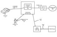
- FIG. 1illustrates an exemplary charging system according to one embodiment of the invention
- FIG. 2illustrates an exemplary embodiment of the charging station illustrated in FIG. 1 according to one embodiment of the invention
- FIG. 3illustrates an exemplary network of charging stations that are each wired to the same circuit breaker according to one embodiment of the invention
- FIG. 4illustrates an exemplary series of messages exchanged between a charging station and a circuit sharing controller during allocation of electric current according to one embodiment of the invention
- FIGS. 5A-Bare flow diagrams illustrating exemplary operations for a circuit sharing process based on load sharing according to one embodiment of the invention
- FIG. 6is a flow diagram illustrating exemplary operations for dynamically adjusting electric current allocations of multiple charging stations on the same electrical circuit when a charging station no longer requests an allocation of current according to one embodiment of the invention
- FIG. 7is a flow diagram illustrating exemplary operations for performing a circuit sharing process that is based on time sharing according to one embodiment of the invention.
- FIG. 8is a flow diagram illustrating exemplary operations for cyclically reallocating electric current in a time sharing process according to one embodiment of the invention.
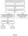
- FIG. 9is a flow diagram illustrating exemplary operations performed in a circuit sharing process that is based on time sharing when a charging station no longer requests an allocation of current according to one embodiment of the invention.
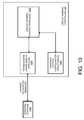
- FIG. 10illustrates an exemplary embodiment of a circuit sharing controller according to one embodiment of the invention.
- references in the specification to “one embodiment”, “an embodiment”, “an example embodiment”, etc.,indicate that the embodiment described may include a particular feature, structure, or characteristic, but every embodiment may not necessarily include the particular feature, structure, or characteristic. Moreover, such phrases are not necessarily referring to the same embodiment. Further, when a particular feature, structure, or characteristic is described in connection with an embodiment, it is submitted that it is within the knowledge of one skilled in the art to effect such feature, structure, or characteristic in connection with other embodiments whether or not explicitly described.
- Coupledmay mean that two or more elements are in direct physical or electrical contact. However, “coupled” may also mean that two or more elements are not in direct contact with each other, but yet still co-operate or interact with each other.
- a charging stationis a piece of equipment, including hardware and software, to charge electric vehicles.
- Such computing devicesstore and communicate (internally and with other computing devices over a network) code and data using machine-readable media, such as machine storage media (e.g., magnetic disks; optical disks; random access memory; read only memory; flash memory devices; phase-change memory) and machine communication media (e.g., electrical, optical, acoustical or other form of propagated signals—such as carrier waves, infrared signals, digital signals, etc.).
- machine storage mediae.g., magnetic disks; optical disks; random access memory; read only memory; flash memory devices; phase-change memory
- machine communication mediae.g., electrical, optical, acoustical or other form of propagated signals—such as carrier waves, infrared signals, digital signals, etc.
- such computing devicestypically include a set of one or more processors coupled to one or more other components, such as a storage device, one or more input/output devices (e.g., a keyboard, a touchscreen, and/or a display), and a network connection.
- the coupling of the set of processors and other componentsis typically through one or more busses and bridges (also termed as bus controllers).
- the storage device and signals carrying the network trafficrespectively represent one or more machine storage media and machine communication media.
- the storage device of a given computing devicetypically stores code and/or data for execution on the set of one or more processors of that device.
- one or more parts of an embodiment of the inventionmay be implemented using different combinations of software, firmware, and/or hardware.
- Electric vehicle charging stationsare coupled with an electric vehicle charging station network server (hereinafter “server”). Multiple charging stations are wired to the same electrical circuit such that if each charging station were operating at full load the capacity of the electrical circuit would be exceeded.
- a dynamic circuit sharing processis performed to prevent the capacity of the electrical circuit from being exceeded while permitting the charging stations that share that electrical circuit to draw electric current through that electrical circuit for at least some amount of time.
- the circuit sharing processis controlled by a circuit sharing controller coupled with the charging stations.
- FIG. 1illustrates an exemplary charging system according to one embodiment of the invention.
- the charging system illustrated in FIG. 1includes the charging station 120 , which is coupled with the power grid 130 over the power line 135 .
- the power grid 130can be owned and/or operated by local utility companies or owned and/or operated by private persons/companies.
- the power line 135is wired to the circuit breaker 125 , which can be separate and remote from the charging station 120 .
- the circuit breaker 125is inaccessible to vehicle operators (e.g., the vehicle operator 145 ).
- vehicle operatorse.g., the vehicle operator 145
- additional charging stations besides the charging station 120are wired on the same power line 135 to the circuit breaker 125 (i.e., multiple charging stations share the same electrical circuit).
- Electric vehiclese.g., the electric vehicle operator 145
- the charging station 120can use the charging station 120 to charge their electric vehicles (e.g., the electric vehicle 110 ).
- the electricity storage devicese.g., batteries, supercapacitors, etc.
- electric vehiclese.g., electric powered vehicles, gasoline/electric powered vehicle hybrids, etc.
- electric vehicle operatorsmay include drivers of electric vehicles, passengers of electric vehicles, and/or service personnel of electric vehicles.
- the operators of electric vehiclesprovide their own charging cord to charge their electric vehicle (e.g., the charging cord 140 belongs to the electric vehicle operator 145 ), while in other embodiments the charging station 120 includes an attached charging cord (e.g., the charging cord 140 is fixably attached to the charging station 120 ).
- the charging station 120can charge in a dual mode at different voltages (e.g., 120V and 240V).
- a fixably attached charging cordis typically used in a higher voltage mode (e.g., 240V) and an unattached charging cord is typically inserted into a power receptacle of the charging station 120 in a lower voltage mode (e.g., 120V).
- the flow of electrical powercan be in either direction on the power line 135 .
- the electric vehicle 110can be charged from the power grid 130 or the power grid 130 can receive power from the electric vehicle 110 (hereinafter referred to as “vehicle-to-grid” (V2G).
- V2Gis particularly attractive for electric vehicles that have their own charging devices, such as battery electric vehicles with regenerative braking and plug-in hybrid vehicles.
- the electric vehicle 110may consume electricity from the power grid 130 as well as transfer electricity to the power grid 130 .
- the charging station 120is also coupled with the server 180 through the data control unit (DCU) 170 .
- the DCU 170acts as a gateway to the server 180 and relays messages and data between the charging station 120 and the server 180 .
- the charging station 120exchanges messages and data with the DCU 170 over the LAN (Local Area Network) link 175 (e.g., WPAN (Wireless Personal Area Network) (e.g., Bluetooth, ZigBee, etc.), or other LAN links (e.g., Ethernet, PLC (Power Line Communication), WiFi, etc.).
- LANLocal Area Network
- the DCU 170exchanges messages and data with the server 180 over the WAN link 185 (e.g., Cellular (e.g., CDMA, GPRS, etc.) WiFi Internet connection, Plain Old Telephone Service, leased line, etc.).
- the DCU 170can be included as part of a charging station (e.g., the charging station 120 or a different charging station coupled with the server 180 ).
- the DCU 170is be a separate device not part of a charging station.
- the charging station 120is coupled with the server 180 directly (i.e., without a connection through a DCU).
- the server 180provides services for multiple charging stations (e.g., authorization service, accounting services, etc.). As will be described in greater detail later herein, in one embodiment the server 180 controls and manages the electric current allocation for multiple charging stations through one or more messages sent to those charging stations (e.g., a message can indicate whether a charging station is permitted to allow electric current to flow on the power line 135 ). In other embodiments the DCU 170 can control and manage the electric current allocation of charging stations.
- the server 180stores vehicle operator information (e.g., operator account information, operator contact information (e.g., operator name, street address, email address, telephone number, etc.)) and charging station configuration information.
- the charging station configuration informationcan include information related to each charging station and the charging sessions on the charging stations.
- the server 180can store the following: the wiring group the charging station belongs to (as used herein, a wiring group corresponds to the physical wiring connection to a common circuit breaker), the electrical circuit capacity of the wiring group (e.g., the breaker size), a trip margin used to prevent false circuit breaker trips, a quantity of electric current that is currently being consumed or transferred, whether a vehicle is plugged into the charging station, the length of charging sessions (current and past), etc.
- the server 180includes a subscriber portal (available through the Internet) which allows subscribers (owners and operators of electric vehicles) to register for service (which may include providing information regarding their electric vehicles, providing payment information, providing contact information, etc.) and perform other functions (e.g., pay for charging sessions, determine availability of charging stations, check the charging status of their electric vehicle(s), etc.).
- the server 180may include a host portal (available through the Internet) which allows owners or administrators of the charging station 120 (and other charging stations) to configure their charging stations and perform other functions (e.g., determine average usage of charging stations, etc.).
- the host portalmay also be used to configure the circuit sharing process described herein.
- Charging stationsmay also be configured using other means in some embodiments of the invention (e.g., through Telnet, user interface, etc.).
- the charging station 120controls the application of electricity between the charging point connection 155 and the power grid 130 by energizing and de-energizing the charging point connection 155 .
- the server 180instructs the charging station 120 when to energize the charging point connection 155 and can also instruct the charging station 120 to de-energize the charging point connection 155 .
- the charging point connection 155is a power receptacle or circuitry for an attached charging cord (e.g., thus the charging station 120 can energize/de-energize the power receptacle or the circuit for an attached charging cord).
- the power receptaclecan be any number of types of receptacles such as receptacles conforming to the NEMA (National Electrical Manufacturers Association) standards 5-15, 5-20, and 14-50 or other standards (e.g., BS 1363, CEE7, etc.) and may be operating at different voltages (e.g., 120V, 240V, 230V, etc.).
- NEMANational Electrical Manufacturers Association
- BS 1363, CEE7, etc.may be operating at different voltages (e.g., 120V, 240V, 230V, etc.).
- Electric vehicle operatorscan request charging sessions for their electric vehicles in different ways in different embodiments of the invention.
- the electric vehicle operator 145can use the communication device 150 to initiate and request a charging session for the electric vehicle 110 .
- the communication device 150may be a WLAN or WPAN device (e.g., one or two-way radio-frequency identification (RFID) device, mobile computing device (e.g., laptops, palmtop, smartphone, multimedia mobile phone, cellular phone, etc.)), ZigBee device, etc.
- RFIDradio-frequency identification
- the communication device 150communicates unique operator-specific information (e.g., operator identification information, etc.) to the charging station 120 (either directly or indirectly through the server 180 ).
- electric vehicle operator 145may use the communication device 150 to monitor the charging status of the electric vehicle 110 .
- the communication device 150may be coupled with the electric vehicle 110 .
- the electric vehicle operator 145may interact with a payment station coupled with the charging station 120 , which may then send appropriate instructions to the charging station 120 regarding the charging of the vehicle 110 (e.g., instructions to energize the charging point connection 155 ).
- the payment stationmay function similarly to a payment station for a parking space.
- a payment station coupled with the charging station 120may be used both for parking payment and charging payment.
- the electric vehicle operator 145may use a user interface of the charging station 120 to request a charging session for the electric vehicle 110 .
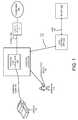
- FIG. 2illustrates an exemplary embodiment of the charging station 120 according to one embodiment of the invention.
- the charging station 120includes the charging point connection 155 , the charging station control modules 205 , the electricity control device 210 , the current measuring device 220 , the RFID reader 230 , the user interface 235 , the display unit 240 , and one or more transceivers 250 (e.g., wired transceiver(s) (e.g., Ethernet, power line communication (PLC), etc.) and/or wireless transceiver(s) (e.g., 802.15.4 (e.g., ZigBee, etc.), Bluetooth, WiFi, Infrared, GPRS/GSM, CDMA, etc.)).
- PLCpower line communication
- FIG. 2illustrates an exemplary architecture of a charging station, and other, different architectures may be used in embodiments of the invention described herein.
- some implementations of charging stationsmay not include a user interface, an RFID reader, or a connection to a network.
- the RFID reader 230reads RFID tags from RFID enabled devices (e.g., smartcards, key fobs, etc., embedded with RFID tag(s)) of operators that want to use the charging station 120 .
- the operator 145may wave/swipe the mobile communication device 150 (if an RFID enabled device) near the RFID reader 230 to request a charging session from the charging station 120 .
- the RFID reader 230passes the information read to one or more of the charging station control modules 205 .
- the charging station control modules 205are programmed to include instructions that establish charging sessions with the vehicles.
- the operator 145is authenticated and authorized based on the information the RFID reader 230 receives.
- the charging station 120locally stores authorization information (e.g., in the configuration/operator data store 270 ), in other embodiments of the invention one of the charging station control modules 205 transmits an authorization request to a remote device (e.g., the server 180 ) via one of the transceivers 250 .
- a remote devicee.g., the server 180
- an authorization requestis transmitted to the data control unit 170 over a WPAN transceiver (e.g., Bluetooth, ZigBee) or a LAN transceiver.
- the data control unit 170relays the authorization request to the server 180 .
- vehicle operatorsmay use the user interface 235 to initiate charging sessions. For example, vehicle operators may enter in account and/or payment information through the user interface 235 .
- the user interface 235may allow the operator 145 to enter in a username/password (or other information) and/or payment information.
- vehicle operatorsmay request charging sessions through devices remote to the charging station 120 (e.g., payment stations coupled with the charging stations).
- the vehicle operatorscan also define a privilege or priority level of their request (e.g., charge immediately, charge anytime, etc.) which may affect the cost of that charging session.
- One or more of the charging station control modules 205cause the charging point connection 155 to be energized.
- one or more of the charging station control modules 205cause the electricity control device 210 to complete the connection of the power line 135 to the power grid 130 .
- the electricity control device 210is a solid-state device that is controlled by the charging station control modules 205 or any other device suitable for controlling the flow of electricity.
- the electricity control device 210includes circuitry to variably control the amount of power draw (e.g. Pulse Width Modulation (PWM) circuitry).
- PWMPulse Width Modulation
- the charging station control modules 205cause the charging point connection 155 to be energized or de-energized based on messages received from the server 180 and/or from the DCU 170 .
- the current measuring device 220measures the amount of current that is flowing on the power line 135 through the charging point connection 155 (e.g., between the vehicle 110 and the charging station 120 ). In some embodiments, in addition to electric vehicles being able to be charged from the power grid 130 , these electric vehicles can be a source of electric power to be transferred to the power grid 130 (vehicle-to-grid (V2G)). While in one embodiment of the invention the current measuring device 220 measures flow of current, in an alternative embodiment of the invention the current measuring device 220 measures power draw.
- the current measuring device 220may include or be coupled with an induction coil or other devices suitable for measuring current.
- the current measuring device 220is coupled with the charging station control modules 205 .
- the charging station control modules 205are programmed with instructions to monitor the current data output from the current measuring device 220 and to calculate the amount of electricity being used over a given time period.
- the display unit 240is used to display messages to the operator 145 (e.g., charging status, confirmation messages, error messages, notification messages, etc.).
- the display unit 240may also display parking information if the charging station 120 is also acting as a parking meter (e.g., amount of time remaining in minutes, parking violation, etc.).
- the configuration/operator data store 270stores configuration information which may be set by administrators, owners, or manufacturers of the charging station 120 .
- FIG. 1illustrates a single charging station 120
- many charging stationsmay be networked to the server 180 (through one or more data control units) and/or to each other.
- multiple charging stationscan share the same circuit, be coupled with the same circuit breaker, and have their power draw controlled by the same circuit sharing controller in some embodiments.
- FIG. 3illustrates an exemplary network of charging stations that share the same electrical circuit and circuit breaker according to one embodiment of the invention.
- the charging station network 300includes the charging stations 120 , 310 , 315 , 325 , and 330 coupled with circuit sharing controller 305 .
- the charging stations 120 , 310 , 315 , 325 , and 330are each wired to the circuit breaker 125 and share the same power line 135 .
- the charging stations 120 , 310 , 315 , 325 , and 330share the same electrical circuit.
- the charging stations 120 , 310 , 315 , 325 , and 330are in the wiring group 350 .
- the circuit sharing controller 305controls and manages the power draw of the charging stations in the wiring group 350 through one or more messages to those charging stations.
- the circuit sharing controller 305can implemented on the server 180 , the DCU 170 , or a separate device coupled with the charging stations of the wiring group 350 .
- the charging stations 120 , 310 , and 325are directly coupled with the circuit sharing controller 305 via the LAN links 175 , 360 , and 370 respectively.
- the charging station 315is indirectly coupled with the circuit sharing controller 305 through the LAN link 365 to the charging station 120 which is itself directly coupled with the circuit sharing controller 305 via the LAN link 175 .
- the charging station 330is indirectly coupled with the circuit sharing controller 305 through the LAN link 375 to the charging station 325 which is itself directly coupled with the circuit sharing controller 305 over the LAN link 370 .
- the charging stations 120 , 310 , 315 , 325 , and 330are also part of the same radio group (as used herein, a radio group is a collection of one or more charging stations that collectively has a single connection to an electric vehicle charging station network server).
- a radio groupis a collection of one or more charging stations that collectively has a single connection to an electric vehicle charging station network server.
- the network architecture illustrated in FIG. 3is exemplary and different embodiments can have different network architectures.
- wiring groupscan include members that are associated with different circuit sharing controllers and a single circuit sharing controller can manage charging stations in multiple wiring groups.
- each charging stationcan have a direct connection with the circuit sharing controller 305 .
- each of the charging stations 120 , 310 , 315 , 325 , and 330share the same circuit (they all receive power through the power line 135 ) and are all each coupled with the same circuit breaker 125 . It should be understood that if activity at one of the charging stations 120 , 310 , 315 , 325 , and 330 causes the circuit breaker 125 to trip then all of the charging stations will lose their electrical connection with the power grid 130 (i.e., they all lose power). Thus, upon the circuit breaker 125 tripping, any charging sessions currently in progress on the charging stations 120 , 310 , 315 , 325 , and 330 will be interrupted.
- multiple charging stations(charging stations 120 , 310 , 315 , 325 , and 330 ) share the same electrical circuit and are wired to the same circuit breaker (circuit breaker 125 ). It should be understood that all of the charging stations in the wiring group 350 may not be delivering their maximum charging output at a given time. For example, some of the charging stations may be idle (not being used). As another example, charging stations may not supply their maximum charging output when an electric car has been fully charged or nearly charged. In order to reduce the cost to install power distribution infrastructure, the size of the circuit is chosen such that the circuit supports something less than a complete utilization of the charging stations (in terms of electric current draw) on the circuit.
- the circuitwill be overloaded and the circuit breaker 125 will trip if all of the charging stations in the wiring group 350 are each supplying current according to their maximum rating. In other words, the circuit will overload if there is a complete utilization of all the charging stations in the wiring group 350 .
- the circuitcan be overloaded by a smaller amount of utilization of the charging stations in the wiring group 350 .
- the charging stations in the wiring group 350in cooperation with the circuit sharing controller 305 , dynamically manage their power delivery such that the total electric current draw on the electrical circuit does not exceed a capacity of the electrical circuit (or a smaller amount of the capacity to protect against spurious breaker trips) while allowing for multiple charging stations to be wired to the same physical electrical circuit.
- the circuit sharing controller 305can instruct the charging stations to commence or cease drawing electric current for charging sessions.
- the circuit sharing controller 305limits the power draw of individual charging stations on the same electrical circuit such that the total power consumed by all of the charging stations on that electrical circuit does not exceed the capacity of the electrical circuit.
- the circuit sharing controller 305dynamically allocates electric current to the charging stations in the wiring group 350 (at least those who are requesting electric current allocation) based on at least an amount of electric current presently allocated on the electrical circuit (e.g., the amount of electric current presently allocated to ones of the charging stations in the wiring group 350 ) in such a way to prevent the capacity of the electrical circuit from being exceeded while permitting each of those charging stations to draw electric current through the electrical circuit for at least some amount of time.
- the electric current allocation of the individual charging stationscan be dynamically adjusted (either increased or decreased) based on a set of one or more factors (e.g., the number of charging stations requesting electric current allocation, the amount of electric current presently allocated on the electrical circuit, the capacity of the electrical circuit, the amount of electric current requested, and one or more charging session attributes (e.g., charging session duration, the type of account associated with the charging session (e.g., privilege of the account), percentage of charge complete, percentage of charge remaining, battery temperature of the electric vehicle, time remaining on the charging session, priority of the charging session, etc.)).
- factorse.g., the number of charging stations requesting electric current allocation, the amount of electric current presently allocated on the electrical circuit, the capacity of the electrical circuit, the amount of electric current requested, and one or more charging session attributes (e.g., charging session duration, the type of account associated with the charging session (e.g., privilege of the account), percentage of charge complete, percentage of charge remaining, battery temperature of the electric vehicle, time remaining on the charging session
- the circuit sharing controller 305controls the amount of electric current that each of the charging stations in the wiring group 350 can draw through a series of messages exchanged between those charging stations and the circuit sharing controller 305 .
- FIG. 4illustrates an exemplary series of messages exchanged between the charging station 120 and the circuit sharing controller 305 during allocation of electric current for the charging station 120 according to one embodiment of the invention.
- FIG. 4will be described with reference to FIG. 3 , however it should be understood that the operations described with reference to FIG. 4 can be performed by embodiments of the invention other than those discussed with reference to FIG. 3 .
- the charging station 120transmits an electric current allocation request message to the circuit sharing controller 305 .
- the electric current allocation request messageincludes an amount of current that the charging station 120 would like to draw from the power grid 130 (the power grid 130 is not shown in FIG. 4 in order not to obscure understanding of the invention).
- the amount of electric current requestedcan vary. For example, upon an initial charging session request, the amount of current can be the maximum amount of current rated for the charging point connection of the charging station. However, after charging has been complete (or substantially complete), the charging station may send an electric current allocation request for less than the maximum amount of current rated for the charging point connection.
- the charging stationstransmit the electric current allocation requests when the amount of current changes (e.g., when an electric vehicle is plugged into the charging station, the electric vehicle has been completely or substantially completely charged), the charging station has timed-out waiting for an acknowledgement message from the circuit sharing controller 305 , and when it powers on and/or undergoes a system restart.
- the amount of current changese.g., when an electric vehicle is plugged into the charging station, the electric vehicle has been completely or substantially completely charged
- the charging stationhas timed-out waiting for an acknowledgement message from the circuit sharing controller 305 , and when it powers on and/or undergoes a system restart.
- the circuit sharing controller 305transmits an acknowledgment message to the charging station 120 in response to receiving the electric current allocation request of operation 4 . 1 .
- the charging station 120does not receive the acknowledgment message in response to the electric current allocation request within a timeout interval, it will resend the request message.
- the acknowledgement message transmitted in operation 4 . 2is optional.
- the circuit sharing controller 305processes the electric current allocation request including determining whether to grant the request with the requested allocation of electric current (or at least a portion of the requested allocation of electric current).
- the circuit sharing controller 305can determine whether to grant the request and what amount of electric current to allocate in different ways in different embodiments of the invention.
- a load sharing processis used where multiple charging stations that are wired to the same electrical circuit can share the load of the circuit such that each of those charging stations are allocated an amount of electric current and the sum of the allocated electric current does not exceed the capacity of the circuit.
- An exemplary load sharing processwill be described in greater detail with respect to FIGS. 5A-B and 6 .
- a time sharing processis used where multiple charging stations that are wired to the same electrical circuit take turns drawing power from the power grid (not necessarily equally) such that the capacity of the circuit is not exceeded.
- An exemplary time sharing processwill be described in greater detail with respect to FIGS. 7-9 .
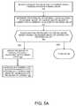
- FIGS. 5A-Bare flow diagrams illustrating exemplary operations for a circuit sharing process based on load sharing according to one embodiment of the invention. In one embodiment, the operations described in reference to FIGS. 5A-B are performed by the circuit sharing controller 305 .
- FIGS. 5A-Bwill be described with reference to the exemplary embodiment of FIG. 3 and will be described with reference to the charging station 120 requesting an allocation of electric current.
- the circuit sharing controller 305receives a request for an allocation of current from the charging station 120 in the wiring group 350 .
- the requestmay indicate the amount of electric current requested.
- the circuit sharing controller 305determines the attributes of the wiring group 350 including the maximum amount of current supported by the wiring group 350 (the maximum amount of current supported by the circuit breaker 125 ) and the amount of current that is presently allocated to the wiring group 350 . It should be understood that the amount of current presently allocated to the wiring group 350 can be distributed among zero or more of the charging stations in the wiring group 350 . That is, there may not be any current allocated to the wiring group 350 or the current may be allocated to one or more members of the wiring group 350 . Flow moves from block 515 to block 520 .
- the circuit sharing controller 305determines whether granting the request for the requested amount of current would exceed the maximum amount of current supported by the wiring group 350 . If the grant would exceed the maximum amount of current that the wiring group 350 supports, flow moves to block 540 (which will be discussed in more detail with reference to FIG. 5B ), otherwise flow moves to block 525 . At block 525 the circuit sharing controller 305 updates the amount of electric current presently allocated for the wiring group 350 by the requested amount. Flow moves from block 525 to block 530 . At block 530 , the circuit sharing controller 305 generates and transmits a set current allocation message to the charging station 120 that indicates a grant of the request for the full amount of the requested allocation of current. With reference to FIG. 4 , the circuit sharing controller 305 transmits the set current allocation message to the charging station 120 at operation 4 . 3 .
- the charging station 120sets its power draw according to the set current allocation message at operation 4 . 4 .
- the charging station control modules 205cause the electricity control device 210 to energize the charging point connection 155 .
- the set current allocation messageincludes an amount of current to allocate (e.g., an upper limit on the amount of current that the charging station 120 can consume from, or provide to, the power grid 130 )
- the charging station control modules 205cause the electricity control device 210 to set that particular amount of power draw.
- the electricity control device 210can include circuitry to variably control the amount of power draw (e.g. Pulse Width Modulation (PWM) circuitry).
- PWMPulse Width Modulation
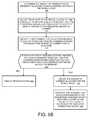
- the circuit sharing controller 305determines the amount of electric current that is presently allocated to each of the charging stations in the wiring group 350 . Flow moves from block 540 to block 545 , where the circuit sharing controller 305 adjusts the amount of electric current that is allocated to one or more of those charging stations such that the requesting charging station can be allocated at least a portion of the requested amount of electric current. In one embodiment, the circuit sharing controller 305 adjusts the electric current allocations of each of the charging stations in the wiring group 350 such that a substantially equivalent amount of electric current is allocated to each of the active charging stations (as used herein, an active charging station is a charging station that is allocated more than a relatively small amount of electric current and currently has a charging session).
- the circuit sharing controller 305adjusts the electric current allocations of one or more of the active charging stations based on a set of one or more charging session attributes that include information about each of the charging sessions on the active charging stations. In such an embodiment, the adjustment does not necessarily result in each of the active charging stations being allocated a substantially equivalent amount of electric current.
- the charging session attributescan include charging session duration, the type of account associated with the charging session (e.g., privilege of the account), percentage of charge complete, percentage of charge remaining, battery temperature of the electric vehicle, time remaining on the charging session, priority of the charging session, etc.
- the circuit sharing controller 305can be configured to more greatly reduce the electric current allocation of a charging station that has a charging session that has been operating longer than another charging station that has a charging session on the same electrical circuit.
- the circuit sharing controller 305adjusts the electric current allocations based on the privilege of the accounts associated with charging sessions on the charging stations (e.g., an account with a higher privilege can be allocated a relatively higher amount of electric current than an account with a lower privilege).
- each set current allocation messageindicates the amount of electric current that has been allocated to a charging station.
- the charging station 120sets its power draw (e.g., the maximum amount of electricity it can draw from the power grid 130 ).
- the charging stationscan set (e.g., reduce or increase) the amount of electric current they are drawing in different ways in different embodiments.
- the electricity control device 210 in the charging station 120includes circuitry and electronics to variably control the output of the charging station (e.g., using Pulse Width Modulation (PWM)).
- PWMPulse Width Modulation
- the charging stationscan control the amount of current drawn by an electric vehicle via a communication link between the charging stations and the electric vehicle (e.g., through a SAE 1772 interface).
- the electric vehiclesaccept a charging cord that connects control signals from the charging station that instructs the electric vehicle e how much current the charging station can supply (e.g., how much current at 220V).
- the circuit sharing controller 305determines for each of the charging stations that have been sent a set current allocation message, whether an acknowledgement message has been received from that charging station (the acknowledgement message indicating the power draw has been set in accordance with the set allocation message). If an acknowledgement message has not been received, flow moves to block 560 where alternative action is taken.
- the alternative actioncan include retransmitting the set current allocation message a number of times.
- the alternative actioncan include transitioning back to block 540 to begin the process of re-allocating the electric current with the assumption that the charging station(s) that have not replied are capable of drawing electric current at their full electric current allocation (their present electric current allocation) and cannot be adjusted). If acknowledgement messages have been received, then flow moves to block 565 .
- the circuit sharing controller 305updates the amount of current allocated for the wiring group and for each of the active charging stations in the wiring group (at least those charging stations that have adjusted their electric current allocation). Flow moves from block 565 to block 570 , where the circuit sharing controller 305 generates and transmits a set allocation message to the requesting charging station which indicates an amount of electric current that has been allocated to that charging station. Upon receipt of a set current allocation message, the requesting charging station sets its power draw in accordance with the set current allocation message.
- FIG. 6is a flow diagram illustrating exemplary operations for dynamically adjusting electric current allocations of multiple charging stations on the same electrical circuit when a charging station no longer requests an allocation of current according to one embodiment of the invention.
- FIG. 6will be described with reference to the exemplary embodiment of FIG. 3 .
- the operations described in FIG. 6are performed by the circuit sharing controller 305 .
- the circuit sharing controller 305receives a message from a charging station (e.g., the charging station 120 ) indicating that an allocation of current is no longer requested. For example, the message can be sent as a result of the charging session ending (e.g., the vehicle operator 110 ending the charging session), the charging session completed (or substantially completed), etc. Flow then moves to block 615 where the circuit sharing controller 305 determines the attributes of the wiring group of the charging station (the wiring group 350 ) including the maximum amount of current supported by the wiring group 350 (the maximum amount of current supported by the circuit breaker 125 ) and the amount of electric current that is presently allocated to the wiring group 350 . Flow then moves to block 620 .
- a charging statione.g., the charging station 120
- the circuit sharing controller 305determines the attributes of the wiring group of the charging station (the wiring group 350 ) including the maximum amount of current supported by the wiring group 350 (the maximum amount of current supported by the circuit breaker 125 ) and the amount of electric current that is presently
- the circuit sharing controller 305reduces the amount of current that is presently allocated to the wiring group by at least a portion of the amount that was allocated to the charging station (a relatively small amount of current may remain allocated to the charging station). Thus, the circuit sharing controller 305 returns at least a portion of the amount of current that was allocated to the charging station to the wiring group (that is, the at least a portion of the allocated amount can be allocated to different ones of the charging stations in the wiring group). Flow moves from block 620 to block 625 .
- the circuit sharing controller 305determines whether any of the charging stations that currently have active charging sessions have an allocated amount of current below their maximum level. If no, then flow moves to block 630 where the process exists. If there are one or more charging stations that currently have active charging sessions that are allocated an amount less then their maximum level, then flow moves to block 635 .
- the circuit sharing controller 305increases the amount of allocated current to one or more of those charging stations from the amount of current returned to the wiring group.
- the amount of allocated currentis substantially equally distributed across the one or more charging stations.
- the amount of current returned to the wiring groupis allocated to those charging stations based on a set of one or more charging session attributes (e.g., charging session duration, type of account associated with the charging session (e.g., privilege of the account), percentage of charge complete, battery temperature of the electric vehicle, percentage of charge remaining, time remaining on the charging session, priority of the charging session, etc.).
- charging session attributese.g., charging session duration, type of account associated with the charging session (e.g., privilege of the account), percentage of charge complete, battery temperature of the electric vehicle, percentage of charge remaining, time remaining on the charging session, priority of the charging session, etc.
- the circuit sharing controller 305generates and transmits a set allocation message to each of those charging stations to increase their amount of electric current allocation.
- those charging stations in the wiring group 350maintain their present allocations. For example, a charging station with an electric current allocation of 15 A will maintain that allocation upon losing connectivity with the circuit sharing controller 305 until connectivity is re-established regardless of whether that charging station is active or idle.
- a relatively small amount of electric currentis allocated to each of the charging stations in the wiring group 350 so that each of the charging stations can at least minimally supply current to electric vehicles in case of a failure of the circuit sharing controller 305 or a loss of network connectivity with the circuit sharing controller 305 .
- FIGS. 5A-B and 6describe an circuit sharing process based on the charging stations sharing the load of the electrical circuit when the circuit would otherwise be overloaded
- the circuit sharing mechanismis based on a time sharing process.
- a time sharing processcan be used when charging stations do not have the capability of throttling their power draw (e.g., the electricity control device either energizes or de-energizes the charging point connection and thus the charging point connection can either draw either all of the power draw it is rated for or no power draw).
- the electricity control device 210energizes and de-energizes the charging point connection 155 but does not include (or does not implement) an electric current throttling mechanism.
- a time sharing processis used to control the duty cycle of the charging station output such that each of the charging stations in a wiring group can take turns drawing power from the power grid while not exceeded the maximum capacity of the electrical circuit based on a time sharing process.
- a charging stationis typically in one of the following three states: idle, electric current allocated, and waiting for electric current allocation.
- idle statean electric vehicle is not coupled with the charging station and a charging session is not active (thus the charging station is not being used).
- the electric current allocated statethe charging station is presently allocated electric current and a charging session is active. Electric current can be drawn from the power grid in the electric current allocated state.
- a charging sessionis active; however electric current is not presently allocated and the charging station is not authorized to draw current from the power grid.
- FIG. 7is a flow diagram illustrating exemplary operations for performing a circuit sharing process that is based on time sharing according to one embodiment of the invention.
- FIG. 7will be described with reference to the exemplary embodiment of FIG. 3 .
- the operations described in FIG. 7are performed by the circuit sharing controller 305 .
- the circuit sharing controller 305receives a request from a charging station for an allocation of current.
- FIG. 7will be described with reference to the circuit sharing controller 305 receiving the request from the charging station 120 .
- the circuit sharing controller 305determines the wiring group of the charging station 120 if necessary (if the circuit sharing controller 305 is providing service for a single wiring group then that wiring group is assumed) and the current charging configuration of the wiring group including the capacity of the circuit of the wiring group (e.g., the maximum amount of current supported by the wiring group) and the amount of current that is presently allocated to the wiring group (to members of the wiring group).
- the circuit sharing controller 305also determines the amount of current the charging station 120 supplies (different charging stations in the wiring group 350 can supply a different amount of current in some embodiments). Flow moves from block 715 to block 720 .
- the circuit sharing controller 305determines whether granting the request (e.g., allowing the charging station 120 to energize the charging point connection 155 and supply the maximum amount of current to the electric vehicle 110 ) would cause the capacity of the electrical circuit to be exceeded. If the capacity would be exceeded, then flow moves to block 740 , otherwise flow moves to block 725 .
- the circuit sharing controller 305updates the amount of current that is allocated for the wiring group. Flow moves from block 725 to block 730 where the circuit sharing controller 305 generates and transmits a message to the charging station 120 indicating a grant of the request. Upon receipt of the message, the charging station 120 energizes the charging point connection 155 to allow electricity to flow between the power grid 130 and the electric vehicle 110 .
- the circuit sharing controller 305cyclically reallocates the current among the charging stations in the wiring group such that each charging station has a turn of receiving current over a time period (at least those charging stations that have an active charging session). That is, the circuit sharing controller 305 cycles through the charging stations in the wiring group such that each of those charging stations can supply current for a certain amount of time in a given time period.
- FIG. 8is a flow diagram illustrating exemplary operations for cyclically reallocating electric current according to one embodiment of the invention. In one embodiment, the operations described in FIG. 8 are part of the operation of block 740 .
- the circuit sharing controller 305sets the requesting charging station as a charging station that is presently waiting for electric current allocation. Other charging station(s) in the wiring group 350 may also be presently waiting for electric current allocation. Flow then moves to block 820 , where the circuit sharing controller 305 determines the number of charging stations that can be actively charging in the wiring group 350 at a given time. By way of example and not limitation, if each charging station of the wiring group 350 supplies 15 A of current, and the circuit has a capacity of 50 A, then three charging stations can be actively charging at any given time without overloading the capacity of the circuit. In some embodiments, the operation described in block 820 is optional. Flow moves from block 820 to block 830 .
- the circuit sharing controller 305selects one of the charging station(s) that presently is allocated current (thus is in the electric current allocated state).
- the circuit sharing controller 305can select that charging station in different ways in different embodiments (e.g., a random selection, a sequential selection, a selection based on one or more charging session attributes (e.g., charging session duration, type of account associated with the charging session (e.g., privilege of the account), percentage of charge complete, percentage of charge remaining, battery temperature of the electric vehicle, time remaining on the charging session, priority of the charging session, etc.), etc.).
- charging session attributese.g., charging session duration, type of account associated with the charging session (e.g., privilege of the account), percentage of charge complete, percentage of charge remaining, battery temperature of the electric vehicle, time remaining on the charging session, priority of the charging session, etc.
- the circuit sharing controller 305generates and transmits a message to that selected charging station in the electric current allocated state.
- the messageinstructs that charging station to suspend the charging session and cease drawing current from the power grid 130 .
- the messageis an attempt by the circuit sharing controller 305 to transition the selected charging station from the electric current allocated state to the waiting for electric current allocation state.
- the circuit sharing controller 305takes alternative action.
- the alternative actioncan include retransmitting the message to the selected charging station a number of times. If the circuit sharing controller 305 still does not receive an acknowledgement message, the circuit sharing controller 305 assumes that the selected charging station is actively charging (or is capable of drawing its maximum amount of current from the power grid 130 ) and flow moves back to block 830 where the circuit sharing controller 305 selects a different charging station that is in the electric current allocated state.
- the circuit sharing controller 305selects one of the charging station(s) that are waiting for electric current allocation.
- the circuit sharing controller 305can select the charging station in different was in different embodiments. For example, the charging station that has been waiting the longest for an allocation of current can be selected. As another example, the selected charging station can be based one or more charging session attributes (e.g., charging session duration, the type of account associated with the charging session (e.g., privilege of the account), percentage of charge complete, percentage of charge remaining, battery temperatures of the electric vehicles, time remaining on the charging session, priority of the charging session, etc.).
- charging session attributese.g., charging session duration, the type of account associated with the charging session (e.g., privilege of the account), percentage of charge complete, percentage of charge remaining, battery temperatures of the electric vehicles, time remaining on the charging session, priority of the charging session, etc.
- the circuit sharing controller 305generates and transmits a message to the selected charging station that authorizes that charging station to draw current from the power grid 130 .
- the circuit sharing controller 305also sets that selected charging station as being in the electric current allocated state.
- the charging stationcan resume (or initiate) its charging session and energize its charging point connection and draw current from the power grid 130 .
- Flowmoves from block 865 to block 870 , where the circuit sharing controller 305 waits for a time period to expire. If the time period has expired, then flow moves back to block 830 .
- multiple charging stationscan share the same electrical circuit without overloading the capacity of that circuit by using the time sharing process described above.
- the charging stationsare treated equally (e.g., a round-robin approach) while in other embodiments the charging stations can be treated differently based on one or more charging session attributes (e.g., charging session duration, the type of account associated with the charging session (e.g., privilege of the account), percentage of charge complete, percentage of charge remaining, battery temperature of the electric vehicle, time remaining on the charging session, priority of the charging session, etc.).
- charging session attributese.g., charging session duration, the type of account associated with the charging session (e.g., privilege of the account), percentage of charge complete, percentage of charge remaining, battery temperature of the electric vehicle, time remaining on the charging session, priority of the charging session, etc.
- FIG. 9is a flow diagram illustrating exemplary operations performed in a circuit sharing process that is based on time sharing when a charging station no longer requests an allocation of current according to one embodiment of the invention.
- FIG. 9will be described with reference to the exemplary embodiment of FIG. 3 .
- the operations described with reference to FIG. 9are performed by the circuit sharing controller 305 .
- the circuit sharing controller 305receives a message from a charging station that indicates that an allocation of current is no longer requested.
- FIG. 9will be described with reference to the circuit sharing controller 305 receiving the message from the charging station 120 .
- the messagecan indicate that the charging session has ended (e.g., the vehicle operator 145 has ended the charging session) or that charging has been completed or substantially completed (e.g., the charging station 120 has measured a relatively small amount of current transferred to the electric vehicle over a continuous amount time, etc.).
- Flowmoves from block 910 to block 915 .
- the circuit sharing controller 305determines the wiring group for the charging station 120 if appropriate (if the circuit sharing controller 305 is providing service for multiple wiring groups) and the current charging configuration of the wiring group (e.g., which (if any) of the charging stations of the wiring group 350 presently have an allocation of current, which (if any) of the charging stations of the wiring group 350 are presently waiting for an allocation of current, which (if any) of the charging stations of the wiring group 350 are idle, the capacity of the electrical circuit, etc.).
- Flowmoves from block 915 to block 920 .
- the circuit sharing controller 305determines whether the charging station 120 presently is allocated current. If the charging station 120 is presently allocated current, then flow moves to block 925 , otherwise flow moves to block 940 where the charging station 120 is removed from the group of charging station(s) that are currently waiting for an allocation of current. At block 925 , the circuit sharing controller 305 de-allocates the current from the charging station 120 and reduces the amount of current that is presently allocated to the wiring group 350 (e.g., returns that amount of current). Flow then moves to block 930 where the circuit sharing controller 305 determines whether there are other charging station(s) that are waiting for an allocation of current in the wiring group 350 . If there are none, then flow moves to block 935 where the process exits, otherwise flow moves back to block 860 of FIG. 8 and the current that was allocated to the charging station 120 can be allocated to one of the other charging station(s) that are waiting for an allocation of current.
- each of those charging stationsmaintain their present state. For example, charging stations in the electric current allocated state remain in that state with that amount of electric current being allocated and those charging stations that are in the waiting for electric current allocation state remain waiting for electric current allocation until connectivity is restored with the circuit sharing controller 305 .
- FIG. 10illustrates an exemplary embodiment of the circuit sharing controller 305 according to one embodiment of the invention.
- the circuit sharing controller 305includes the transceivers (wired and/or wireless) 1030 coupled with one or more circuit sharing control modules 1020 .
- the one or more circuit sharing control modules 1020are coupled with the one or more charging station configuration structure(s) 1040 .
- the circuit sharing control module(s) 1020perform the circuit sharing mechanism described herein (e.g., load sharing and/or time sharing for different wiring groups).
- Current allocation messagesare exchanged between the charging stations 1050 and the transceiver(s) 1030 (e.g., current allocation request messages, current allocation set messages, acknowledgement messages, etc.).
- the charging station configuration structure(s) 1040stores charging station configuration information (e.g., for each charging station, the wiring group for that charging station, the capacity of the electrical circuit of that wiring group, a trip margin, a quantity of electric current allocated for members of that wiring group, whether a vehicle is plugged into the charging station, the duration of charging session (current and past), etc.).
- charging station configuration informatione.g., for each charging station, the wiring group for that charging station, the capacity of the electrical circuit of that wiring group, a trip margin, a quantity of electric current allocated for members of that wiring group, whether a vehicle is plugged into the charging station, the duration of charging session (current and past), etc.).
- Embodiments of the invention described hereincan reduce the cost of the power distribution infrastructure needed to deploy charging stations. For example, the number of service drops and meters, the amount of heavy gauge wiring, etc., can be reduced. Additionally, the need for power utilities to add or replace local transformers to support the load of the charging stations is also reduced.
- the electric current allocation request messagesalso include information for authorizing the vehicle operator associated with the charging session. If the vehicle operator is not authorized, that charging station will not be allocated electric current.
- the circuit sharing mechanismis distributed among the charging stations in a wiring group (e.g., distributed amount the charging stations 120 , 310 , 315 , 325 , and 330 of the wiring group 350 ).
Landscapes
- Engineering & Computer Science (AREA)
- Power Engineering (AREA)
- Transportation (AREA)
- Mechanical Engineering (AREA)
- Life Sciences & Earth Sciences (AREA)
- Sustainable Development (AREA)
- Sustainable Energy (AREA)
- Health & Medical Sciences (AREA)
- Artificial Intelligence (AREA)
- Computer Vision & Pattern Recognition (AREA)
- Evolutionary Computation (AREA)
- Medical Informatics (AREA)
- Software Systems (AREA)
- Physics & Mathematics (AREA)
- General Physics & Mathematics (AREA)
- Automation & Control Theory (AREA)
- Charge And Discharge Circuits For Batteries Or The Like (AREA)
Abstract
Description
Claims (8)
Priority Applications (9)
| Application Number | Priority Date | Filing Date | Title |
|---|---|---|---|
| US12/508,488US8013570B2 (en) | 2009-07-23 | 2009-07-23 | Electrical circuit sharing for electric vehicle charging stations |
| US13/226,422US8502500B2 (en) | 2009-07-23 | 2011-09-06 | Electrical circuit sharing for electric vehicle charging stations |
| US13/948,879US9201407B2 (en) | 2009-07-23 | 2013-07-23 | Managing electric current allocation of electric vehicle charging stations |
| US14/298,842US9201408B2 (en) | 2009-07-23 | 2014-06-06 | Managing electric current allocation between charging equipment for charging electric vehicles |
| US14/956,264US9469211B2 (en) | 2009-07-23 | 2015-12-01 | Managing electrical current allocation between charging equipment for charging electric vehicles |
| US15/295,824US9908427B2 (en) | 2009-07-23 | 2016-10-17 | Managing electric current allocation between charging equipment for charging electric vehicles |
| US15/913,684US10252633B2 (en) | 2009-07-23 | 2018-03-06 | Managing electric current allocation between charging equipment for charging electric vehicles |
| US16/379,361US10913372B2 (en) | 2009-07-23 | 2019-04-09 | Managing electric current allocation between charging equipment for charging electric vehicles |
| US17/171,588US11780345B2 (en) | 2009-07-23 | 2021-02-09 | Managing electric current allocation between charging equipment for charging electric vehicles |
Applications Claiming Priority (1)
| Application Number | Priority Date | Filing Date | Title |
|---|---|---|---|
| US12/508,488US8013570B2 (en) | 2009-07-23 | 2009-07-23 | Electrical circuit sharing for electric vehicle charging stations |
Related Child Applications (1)
| Application Number | Title | Priority Date | Filing Date |
|---|---|---|---|
| US13/226,422DivisionUS8502500B2 (en) | 2009-07-23 | 2011-09-06 | Electrical circuit sharing for electric vehicle charging stations |
Publications (2)
| Publication Number | Publication Date |
|---|---|
| US20100134067A1 US20100134067A1 (en) | 2010-06-03 |
| US8013570B2true US8013570B2 (en) | 2011-09-06 |
Family
ID=42222200
Family Applications (9)
| Application Number | Title | Priority Date | Filing Date |
|---|---|---|---|
| US12/508,488ActiveUS8013570B2 (en) | 2009-07-23 | 2009-07-23 | Electrical circuit sharing for electric vehicle charging stations |
| US13/226,422Active2029-12-11US8502500B2 (en) | 2009-07-23 | 2011-09-06 | Electrical circuit sharing for electric vehicle charging stations |
| US13/948,879Active2029-12-02US9201407B2 (en) | 2009-07-23 | 2013-07-23 | Managing electric current allocation of electric vehicle charging stations |
| US14/298,842ActiveUS9201408B2 (en) | 2009-07-23 | 2014-06-06 | Managing electric current allocation between charging equipment for charging electric vehicles |
| US14/956,264ActiveUS9469211B2 (en) | 2009-07-23 | 2015-12-01 | Managing electrical current allocation between charging equipment for charging electric vehicles |
| US15/295,824ActiveUS9908427B2 (en) | 2009-07-23 | 2016-10-17 | Managing electric current allocation between charging equipment for charging electric vehicles |
| US15/913,684ActiveUS10252633B2 (en) | 2009-07-23 | 2018-03-06 | Managing electric current allocation between charging equipment for charging electric vehicles |
| US16/379,361ActiveUS10913372B2 (en) | 2009-07-23 | 2019-04-09 | Managing electric current allocation between charging equipment for charging electric vehicles |
| US17/171,588Active2029-11-21US11780345B2 (en) | 2009-07-23 | 2021-02-09 | Managing electric current allocation between charging equipment for charging electric vehicles |
Family Applications After (8)
| Application Number | Title | Priority Date | Filing Date |
|---|---|---|---|
| US13/226,422Active2029-12-11US8502500B2 (en) | 2009-07-23 | 2011-09-06 | Electrical circuit sharing for electric vehicle charging stations |
| US13/948,879Active2029-12-02US9201407B2 (en) | 2009-07-23 | 2013-07-23 | Managing electric current allocation of electric vehicle charging stations |
| US14/298,842ActiveUS9201408B2 (en) | 2009-07-23 | 2014-06-06 | Managing electric current allocation between charging equipment for charging electric vehicles |
| US14/956,264ActiveUS9469211B2 (en) | 2009-07-23 | 2015-12-01 | Managing electrical current allocation between charging equipment for charging electric vehicles |
| US15/295,824ActiveUS9908427B2 (en) | 2009-07-23 | 2016-10-17 | Managing electric current allocation between charging equipment for charging electric vehicles |
| US15/913,684ActiveUS10252633B2 (en) | 2009-07-23 | 2018-03-06 | Managing electric current allocation between charging equipment for charging electric vehicles |
| US16/379,361ActiveUS10913372B2 (en) | 2009-07-23 | 2019-04-09 | Managing electric current allocation between charging equipment for charging electric vehicles |
| US17/171,588Active2029-11-21US11780345B2 (en) | 2009-07-23 | 2021-02-09 | Managing electric current allocation between charging equipment for charging electric vehicles |
Country Status (1)
| Country | Link |
|---|---|
| US (9) | US8013570B2 (en) |
Cited By (47)
| Publication number | Priority date | Publication date | Assignee | Title |
|---|---|---|---|---|
| US20100066170A1 (en)* | 2008-08-12 | 2010-03-18 | Mike Schuler | Method and Apparatus for Allocating Electricity from a Distributor |
| US20110037429A1 (en)* | 2009-08-11 | 2011-02-17 | Siemens Industry, Inc. | Electrical distribution system recharging station for electric vehicles |
| US20120161704A1 (en)* | 2009-08-10 | 2012-06-28 | Rwe Ag | Charging station for electric vehicles with network stabilization |
| US20120277927A1 (en)* | 2011-04-27 | 2012-11-01 | Ev Patent Holdings, Llc | Electric vehicle clustered charge distribution and prioritization method,system and apparatus |
| US8421592B1 (en)* | 2008-10-15 | 2013-04-16 | Sprint Communications Company L.P. | Mediation of electric vehicle charging by wireless network provider |
| WO2013115428A1 (en)* | 2012-01-31 | 2013-08-08 | 엘에스전선(주) | Electric vehicle charging system and electric vehicle charging method |
| US20140062419A1 (en)* | 2011-05-20 | 2014-03-06 | Panasonic Corporation | Charging control device and charging control system |
| US8725330B2 (en) | 2010-06-02 | 2014-05-13 | Bryan Marc Failing | Increasing vehicle security |
| US8981718B2 (en) | 2012-05-25 | 2015-03-17 | Nissan North America, Inc. | Serial multi-vehicle quick charge station |
| US9082112B2 (en) | 2010-12-15 | 2015-07-14 | Symbotic, LLC | Autonomous transport vehicle charging system |
| US9102240B2 (en) | 2011-04-25 | 2015-08-11 | Poulsen Hybrid, Llc | Charging station for electric vehicles |
| CN104916048A (en)* | 2015-07-02 | 2015-09-16 | 江苏德和新能源科技有限公司 | Charging control system and method based on Internet thinking, cloud platform and APP payment |
| US9148027B2 (en) | 2012-07-30 | 2015-09-29 | General Electric Company | Method and system for charging of electric vehicles |
| US9290104B2 (en) | 2012-08-24 | 2016-03-22 | The Regents Of The University Of California | Power control apparatus and methods for electric vehicles |
| US9315109B2 (en) | 2013-11-02 | 2016-04-19 | At&T Intellectual Property I, L.P. | Methods, systems, and products for charging batteries |
| US9348381B2 (en) | 2011-10-19 | 2016-05-24 | Zeco Systems Pte Ltd | Methods and apparatuses for charging of electric vehicles |
| US20160176306A1 (en)* | 2012-10-19 | 2016-06-23 | Christopher S. Outwater | System and method for managing vehicle charging stations |
| US9440548B2 (en) | 2012-08-08 | 2016-09-13 | Cognizant Technology Solutions India Pvt. Ltd. | Method and system for managing and controlling electrical vehicle charging events |
| US9469208B2 (en) | 2013-03-15 | 2016-10-18 | Symbotic, LLC | Rover charging system |
| US20160378074A1 (en)* | 2011-04-15 | 2016-12-29 | Astrolink International Llc | System and method for single and multizonal optimization of utility services delivery and utilization |
| US9573478B2 (en) | 2014-11-14 | 2017-02-21 | Schneider Electric USA, Inc. | EVSE doubler add-on unit |
| US9707850B2 (en) | 2014-11-18 | 2017-07-18 | Schneider Electric USA, Inc. | EVSE handle with automatic thermal shut down by NTC to ground |
| US9744870B2 (en) | 2014-11-11 | 2017-08-29 | Empire Technology Development Llc | Wirelessly charging vehicles moving in vehicle convoy |
| US20170282736A1 (en)* | 2016-04-01 | 2017-10-05 | Ijuze Corporation Pte Ltd. | Automated system for managing and providing a network of charging stations |
| US9804034B2 (en) | 2014-11-14 | 2017-10-31 | Schneider Electric USA, Inc. | EVSE with cordset handle temperature measurement |
| DE102017116070A1 (en) | 2016-07-18 | 2018-01-18 | GM Global Technology Operations LLC | HOME CHARGING SYSTEM FOR AN ELECTRIC VEHICLE |
| US10001514B2 (en) | 2013-06-13 | 2018-06-19 | Astrolink International Llc | System and method for detecting and localizing non-technical losses in an electrical power distribution grid |
| US10020677B2 (en) | 2014-10-30 | 2018-07-10 | Astrolink International Llc | System, method, and apparatus for grid location |
| US10079765B2 (en) | 2014-10-30 | 2018-09-18 | Astrolink International Llc | System and methods for assigning slots and resolving slot conflicts in an electrical distribution grid |
| US10097240B2 (en) | 2013-02-19 | 2018-10-09 | Astrolink International, Llc | System and method for inferring schematic and topological properties of an electrical distribution grid |
| US10150380B2 (en)* | 2016-03-23 | 2018-12-11 | Chargepoint, Inc. | Dynamic allocation of power modules for charging electric vehicles |
| US10181734B2 (en)* | 2016-04-22 | 2019-01-15 | Richtek Technology Corporation | Charging control method and charging system, power delivery unit, and power receiver control circuit using the method |
| US10252633B2 (en) | 2009-07-23 | 2019-04-09 | Chargepoint, Inc. | Managing electric current allocation between charging equipment for charging electric vehicles |
| US20190184850A1 (en)* | 2017-12-01 | 2019-06-20 | California Institute Of Technology | Optimization Framework and Methods for Adaptive EV Charging |
| US10396582B2 (en)* | 2015-07-01 | 2019-08-27 | Maxim Integrated Products, Inc. | Master slave charging architecture with communication between chargers |
| US10744883B2 (en) | 2016-05-25 | 2020-08-18 | Chargepoint, Inc. | Dynamic allocation of power modules for charging electric vehicles |
| US10749571B2 (en) | 2013-06-13 | 2020-08-18 | Trc Companies, Inc. | System and methods for inferring the feeder and phase powering an on-grid transmitter |
| US20210080282A1 (en)* | 2017-04-03 | 2021-03-18 | Power Hero Corp. | Universal automated system for identifying, registering and verifying the existence, location and characteristics of electric and other power outlets by random users and for retrieval and utilization of such parametric data and outlets by all users |
| US11171509B2 (en) | 2016-02-25 | 2021-11-09 | California Institute Of Technology | Adaptive charging network using adaptive charging stations for electric vehicles |
| AU2020220130B2 (en)* | 2017-08-04 | 2022-01-06 | Kabushiki Kaisha Funabashi Soukou | Power supply switching device and power supply system |
| US20220024335A1 (en)* | 2020-07-24 | 2022-01-27 | Ford Global Technologies, Llc | Electrical charge pattern validation |
| US11338693B2 (en)* | 2016-09-15 | 2022-05-24 | Bayerische Motoren Werke Aktiengesellschaft | Method for charging a battery-operated vehicle |
| US11376981B2 (en) | 2019-02-08 | 2022-07-05 | California Institute Of Technology | Systems and methods for adaptive EV charging |
| US20220348102A1 (en)* | 2019-09-26 | 2022-11-03 | Liikennevirta Oy / Virta Ltd | Control of electric vehicle charging |
| US20230264591A1 (en)* | 2022-02-21 | 2023-08-24 | Cyberswitchingpatents, Llc | Electric vehicle charging master controller |
| US11951863B2 (en) | 2009-12-17 | 2024-04-09 | Chargepoint, Inc. | Method and apparatus for management of current load to an electric vehicle charging station in a residence |
| US12077058B1 (en)* | 2023-05-02 | 2024-09-03 | InCharge Energy, Inc. | Systems and methods for managing electric vehicle charging networks using an open charge point protocol proxy |
Families Citing this family (208)
| Publication number | Priority date | Publication date | Assignee | Title |
|---|---|---|---|---|
| US7993155B2 (en) | 2008-09-19 | 2011-08-09 | Better Place GmbH | System for electrically connecting batteries to electric vehicles |
| US20110223459A1 (en)* | 2008-09-19 | 2011-09-15 | Yoav Heichal | Multi-Motor Latch Assembly |
| US8006793B2 (en)* | 2008-09-19 | 2011-08-30 | Better Place GmbH | Electric vehicle battery system |
| US8324859B2 (en)* | 2008-12-15 | 2012-12-04 | Comverge, Inc. | Method and system for co-operative charging of electric vehicles |
| WO2010137307A1 (en)* | 2009-05-26 | 2010-12-02 | 日立オートモティブシステムズ株式会社 | Vehicle operation support system and vehicle operation support method |
| US8350525B2 (en)* | 2009-08-05 | 2013-01-08 | Credit Lock, Llc | Charging vehicles in a parking area |
| US20110145141A1 (en)* | 2009-10-02 | 2011-06-16 | James Blain | Method and apparatus for recharging electric vehicles |
| US20110140658A1 (en)* | 2009-12-15 | 2011-06-16 | Liberty Plugins, Inc. | Automated Parking Garage with Electric Vehicle Charging |
| US20120319650A1 (en)* | 2010-03-29 | 2012-12-20 | Toshiya Iwasaki | Recharging system |
| US9561730B2 (en)* | 2010-04-08 | 2017-02-07 | Qualcomm Incorporated | Wireless power transmission in electric vehicles |
| US10343535B2 (en) | 2010-04-08 | 2019-07-09 | Witricity Corporation | Wireless power antenna alignment adjustment system for vehicles |
| US8427104B2 (en)* | 2010-04-22 | 2013-04-23 | The Raymond Corporation | Method of allocating batteries for use on specific industrial vehicles in a fleet |
| US9439455B2 (en)* | 2010-04-30 | 2016-09-13 | Fontem Holdings 4 B.V. | Electronic smoking device |
| JP5647057B2 (en)* | 2010-05-19 | 2014-12-24 | 株式会社日立製作所 | Charging apparatus, charging control unit, and charging control method |
| DE102010026689A1 (en)* | 2010-07-09 | 2012-01-12 | Siemens Aktiengesellschaft | Method and control unit for charging a vehicle battery |
| WO2012148596A1 (en) | 2011-04-29 | 2012-11-01 | Electric Transportation Engineering Corporation, D/B/A Ecotality North America | System for measuring electricity and method of providing and using the same |
| WO2012148597A1 (en) | 2011-04-29 | 2012-11-01 | Electric Transportation Engineering Corporation, D/B/A Ecotality North America | Device to facilitate moving an electrical cable of an electric vehicle charging station and method of providing the same |
| WO2012012008A2 (en)* | 2010-07-23 | 2012-01-26 | Electric Transportation Engineering Corp. | System for advertising and communicating at a vehicle charging station and method of using the same |
| US20120044843A1 (en)* | 2010-08-17 | 2012-02-23 | Levy Paul S | Method of interconnecting multiple Electrical Vehicle Slave Charge Stations to a single Master Charge Station using a central hub or daisy chain connection means |
| JP5471982B2 (en)* | 2010-09-03 | 2014-04-16 | 株式会社豊田自動織機 | Sharing charging system |
| JP5426765B2 (en)* | 2010-09-24 | 2014-02-26 | 株式会社東芝 | Determination device, determination method, and determination program |
| DE102010043001A1 (en)* | 2010-10-27 | 2012-05-03 | Siemens Aktiengesellschaft | Charging system and method for charging vehicle batteries |
| PT2633599T (en)* | 2010-10-27 | 2020-02-03 | The Aes Corp | METHODS, ADAPTERS AND APPLIANCES FOR USE WITH ELECTRICAL DEVICES TO MANAGE ENERGY SERVICES |
| US8509988B2 (en)* | 2010-11-16 | 2013-08-13 | Honda Motor Co., Ltd. | Cellular communication strategy |
| US20120130891A1 (en)* | 2010-11-18 | 2012-05-24 | Parkmobile USA | Method of processing a transaction for a parking session |
| DE102011008676A1 (en)* | 2011-01-15 | 2012-07-19 | Daimler Ag | System and method for charging batteries of vehicles |
| US8896265B2 (en) | 2011-01-31 | 2014-11-25 | Toyota Motor Engineering & Manufacturing North America, Inc. | Charge transfer devices for plug-in electric vehicles |
| CN202068223U (en)* | 2011-03-01 | 2011-12-07 | 东南大学 | Vehicle-based charging-discharging device based on V2G technology |
| ITMO20110054A1 (en)* | 2011-03-09 | 2012-09-10 | Meta System Spa | EQUIPMENT AND METHOD FOR RECHARGING BATTERIES OF ELECTRIC OR SIMILAR VEHICLES |
| US10778008B2 (en)* | 2011-03-28 | 2020-09-15 | Paul S. Levy | Method and process for acquiring and delivering electric vehicle owner-operator preference data which is used to schedule and regulate the charging of multiple electric vehicle batteries within a shared local power distribution network |
| JP5416735B2 (en)* | 2011-04-28 | 2014-02-12 | 株式会社日立製作所 | Power monitoring control device and power monitoring control system |
| WO2012146306A2 (en)* | 2011-04-29 | 2012-11-01 | Siemens Aktiengesellschaft | Method for limiting electrical power |
| US9283863B2 (en) | 2011-05-04 | 2016-03-15 | Siemens Aktiengesellschaft | Method and apparatus for providing electrical energy |
| WO2012163396A1 (en)* | 2011-05-30 | 2012-12-06 | Siemens Aktiengesellschaft | Limiting power or current intensity in charging devices |
| WO2012163421A1 (en)* | 2011-06-01 | 2012-12-06 | Siemens Aktiengesellschaft | Assignment of power or current strength to charging devices |
| US8706312B2 (en)* | 2011-06-02 | 2014-04-22 | General Electric Company | Charging device and methods of authorizing a charging request |
| JP5851730B2 (en)* | 2011-06-15 | 2016-02-03 | 三菱重工業株式会社 | Charging system, charging management device, charging management method, and program |
| US9069019B2 (en)* | 2011-06-20 | 2015-06-30 | Chargepoint, Inc. | Apparatus and method for measuring ground impedance of a circuit |
| US8798803B2 (en)* | 2011-06-28 | 2014-08-05 | General Electric Company | Control system for an electric power system |
| US9000721B2 (en)* | 2011-06-29 | 2015-04-07 | General Electric Company | Systems and methods for charging |
| US9139102B2 (en)* | 2011-07-19 | 2015-09-22 | Siemens Industry, Inc. | Electric vehicle charging station with a field upgradeable communications facility |
| ES2748199T3 (en) | 2011-07-26 | 2020-03-13 | Gogoro Inc | Apparatus, method and article for providing information on the availability of energy storage devices in an energy storage device collection, charging and dispensing machine |
| US10186094B2 (en) | 2011-07-26 | 2019-01-22 | Gogoro Inc. | Apparatus, method and article for providing locations of power storage device collection, charging and distribution machines |
| TWI584976B (en) | 2011-07-26 | 2017-06-01 | 睿能創意公司 | Dynamically limiting vehicle operation for best effort economy |
| WO2013016570A1 (en) | 2011-07-26 | 2013-01-31 | Gogoro, Inc. | Apparatus, method and article for authentication, security and control of power storage devices, such as batteries, based on user profiles |
| JP6026535B2 (en) | 2011-07-26 | 2016-11-16 | ゴゴロ インク | RESERVED POWER STORAGE DEVICE DEVICE, METHOD, AND ARTICLE FOR RESERVING A POWER STORAGE DEVICE IN A COLLECTION, CHARGING AND DISTRIBUTION MACHINE |
| CN103891089B (en) | 2011-07-26 | 2016-10-12 | 睿能创意公司 | Apparatus, method and article for authentication, security and control of electric power storage devices such as batteries |
| JP6422119B2 (en)* | 2011-07-26 | 2018-11-14 | ゴゴロ インク | Apparatus, method and article for redistributing a power storage device such as a battery between collection charge distribution devices |
| US9424697B2 (en) | 2011-07-26 | 2016-08-23 | Gogoro Inc. | Apparatus, method and article for a power storage device compartment |
| TWI486909B (en) | 2011-07-26 | 2015-06-01 | 睿能創意公司 | Apparatus, method and article for providing vehicle diagnostic data |
| US8917054B2 (en)* | 2011-08-08 | 2014-12-23 | Lear Corporation | Charger system with safety guardian |
| KR20140078623A (en)* | 2011-08-16 | 2014-06-25 | 베터 플레이스 게엠베하 | Estimation and management of loads in electric vehicle networks |
| WO2013023701A1 (en)* | 2011-08-18 | 2013-02-21 | Siemens Aktiengesellschaft | Providing electrical energy |
| US8810198B2 (en)* | 2011-09-02 | 2014-08-19 | Tesla Motors, Inc. | Multiport vehicle DC charging system with variable power distribution according to power distribution rules |
| US9368959B2 (en) | 2011-09-06 | 2016-06-14 | Robert W. Wright, JR. | Displacement safety system for electrical charging stations |
| DE102011083150A1 (en)* | 2011-09-21 | 2013-03-21 | Siemens Aktiengesellschaft | Controlling energy recovery from a number of automotive accumulators into a power grid |
| JP5874268B2 (en)* | 2011-09-22 | 2016-03-02 | 日産自動車株式会社 | Charging apparatus and charging method |
| US8390252B2 (en)* | 2011-09-23 | 2013-03-05 | General Electric Company | Charging device, system, and method for controlling a charging device |
| EP2763878B1 (en)* | 2011-10-03 | 2020-08-05 | Husqvarna Ab | Battery powered vehicle with immobilizing charger plug |
| DE102011084216A1 (en)* | 2011-10-10 | 2013-04-11 | Robert Bosch Gmbh | Device for controlling electrical charging of electric car in e.g. multi-storey car park, has measuring instrument determining electric power, and control unit controlling certain portion of power such that maximum value is not exceeded |
| US8358102B2 (en)* | 2011-10-21 | 2013-01-22 | General Electric Company | System, charging device, and method of charging a power storage device |
| US8384359B2 (en) | 2011-10-21 | 2013-02-26 | General Electric Company | System, charging device, and method of charging a power storage device |
| US8332078B2 (en)* | 2011-10-21 | 2012-12-11 | General Electric Company | System, charging device, and method of supplying current to a power storage device |
| US9304566B2 (en)* | 2011-10-31 | 2016-04-05 | General Electric Company | Systems and methods for use in communicating with a charging station |
| JP5234159B2 (en) | 2011-10-31 | 2013-07-10 | トヨタ自動車株式会社 | A vehicle including a power storage unit capable of discharging (power feeding) to an external load, a discharge system including the vehicle and a power cable, a discharge control method for the power storage unit, and a device outside the vehicle used in the discharge system. |
| JP5218800B2 (en)* | 2011-10-31 | 2013-06-26 | トヨタ自動車株式会社 | VEHICLE HAVING POWER STORAGE UNIT AND CHARGE / DISCHARGE SYSTEM INCLUDING THE VEHICLE AND ENERGY MANAGEMENT |
| JP5967516B2 (en)* | 2011-11-22 | 2016-08-10 | パナソニックIpマネジメント株式会社 | Power management apparatus, power management program, and power distribution system |
| US8872480B2 (en)* | 2011-12-01 | 2014-10-28 | Siemens Industry, Inc. | Current monitoring and limiting apparatus, system and method for electric vehicle supply equipment |
| KR101544477B1 (en)* | 2011-12-13 | 2015-08-18 | 주식회사 케이티 | A power control method of electrical devices using control algorithm of maximum demand power |
| FR2984622B1 (en)* | 2011-12-19 | 2014-05-16 | Schneider Electric Ind Sas | METHOD FOR CONTROLLING AND OPTIMIZING THE OPERATION OF A LOADING TERMINAL OF AN ELECTRIC VEHICLE AND LOADING TERMINAL FOR CARRYING OUT SAID METHOD |
| NL2008058C2 (en)* | 2011-12-29 | 2013-07-03 | Epyon B V | Method, system and charger for charging a battery of an electric vehicle. |
| EP2814687B1 (en)* | 2012-02-13 | 2019-04-10 | Accenture Global Services Limited | Electric vehicle distributed intelligence |
| WO2013122766A1 (en) | 2012-02-16 | 2013-08-22 | Lightening Energy | Energy banking system and method using rapidly rechargeable batteries |
| IL218213A0 (en)* | 2012-02-20 | 2012-07-31 | Better Place GmbH | Charging management method and system |
| US9656567B2 (en)* | 2012-03-15 | 2017-05-23 | Chargepoint, Inc. | Electric vehicle charging station dynamically responding to power limit messages based on a recent history of power provided |
| JP6013752B2 (en)* | 2012-03-29 | 2016-10-25 | 株式会社東芝 | Charge / discharge control program, management server, charge / discharge control system |
| EP2645514A1 (en)* | 2012-03-30 | 2013-10-02 | EH Europe GmbH | Method and apparatus for controlling battery chargers |
| US20130338820A1 (en)* | 2012-05-30 | 2013-12-19 | Adrian Corbett | Automated Electric Vehicle Charging Station |
| US9118183B2 (en) | 2012-06-07 | 2015-08-25 | Schneider Electric USA, Inc. | Auto detection of vehicle type connected to an EVSE |
| FR2991828B1 (en)* | 2012-06-07 | 2015-11-20 | Electricite De France | CHARGING DEVICE FOR BATTERY ON BOARD IN AN ELECTRIC VEHICLE OR IN A RECHARGEABLE HYBRID ELECTRIC VEHICLE |
| EP2920027B1 (en) | 2012-11-16 | 2021-10-13 | Gogoro Inc. | System and method for vehicle turn signals |
| US9277191B2 (en) | 2012-12-12 | 2016-03-01 | Schneider Electric USA, Inc. | Security monitoring systems, methods and devices for electric vehicle charging stations |
| US9637016B2 (en)* | 2012-12-14 | 2017-05-02 | Agim GJINALI | Fast charging system for electric vehicles |
| EP2937243B1 (en) | 2012-12-20 | 2020-03-18 | Ingeteam Power Technology, S.A. | Method for power management in electrical installations |
| DE102013000981A1 (en)* | 2013-01-22 | 2014-07-24 | Rwe Ag | Method and system for exchanging charging information between a charging station and a cash register system |
| JP6081817B2 (en)* | 2013-02-26 | 2017-02-15 | 三菱重工業株式会社 | OBE and EV management system |
| US20140266004A1 (en)* | 2013-03-14 | 2014-09-18 | Zevtron, LLC | Electric vehicle charging system |
| US11075530B2 (en)* | 2013-03-15 | 2021-07-27 | Gogoro Inc. | Modular system for collection and distribution of electric storage devices |
| ES2523415B1 (en)* | 2013-05-20 | 2015-09-02 | Mario Juan MARMOLEJO GONZÁLEZ | System and procedure for charging electric vehicles |
| EP3016237A4 (en)* | 2013-06-25 | 2017-03-08 | Nec Corporation | Method for controlling charging power, system for controlling charging power, and program |
| DE102013212489B4 (en)* | 2013-06-27 | 2024-05-29 | Bayerische Motoren Werke Aktiengesellschaft | Power availability interface |
| FR3008246B1 (en) | 2013-07-03 | 2017-07-07 | Schneider Electric Ind Sas | SYSTEM FOR ELECTRICALLY CHARGING A PLURALITY OF ELECTRIC VEHICLES AND METHOD FOR DISTRIBUTING THE ELECTRICAL POWER DELIVERED BY AN ELECTRIC POWER SUPPLY OF SUCH A SYSTEM |
| CN105453371A (en)* | 2013-07-31 | 2016-03-30 | 日本电气株式会社 | Power management system and power management method |
| US9586497B2 (en)* | 2013-08-22 | 2017-03-07 | Lightening Energy | Electric vehicle recharging station including a battery bank |
| CN103475059B (en) | 2013-09-17 | 2015-10-28 | 山东鲁能智能技术有限公司 | Multiple-channel output cooperation control electric automobile integrated charger supervisory control system and method |
| CN103457335B (en)* | 2013-09-17 | 2016-05-11 | 山东鲁能智能技术有限公司 | Electric automobile intelligent integral charger device |
| US9056553B2 (en) | 2013-10-31 | 2015-06-16 | Honda Motor Co., Ltd. | Methods and systems for charging an electric vehicle |
| CA2871232C (en)* | 2014-05-29 | 2018-10-02 | Addenergie Technologies Inc. | Method and system for managing power sharing of a plurality of charging stations sharing the same portion of an electrical network |
| CA2871242C (en)* | 2014-05-29 | 2020-10-27 | Addenergie Technologies Inc. | Method and system for managing power demand of a plurality of charging stations sharing the same portion of an electrical network |
| JP2016010246A (en)* | 2014-06-25 | 2016-01-18 | 三菱電機株式会社 | Charging/discharging device for electric vehicle, charging/discharging system for electric vehicle, and operation method of charging/discharging system for electric vehicle |
| EP3166815A1 (en)* | 2014-07-10 | 2017-05-17 | Volta Industries, LLC | Systems and methods for providing targeted advertisements to a charging station for electric vehicles |
| CN106605338B (en) | 2014-08-11 | 2019-07-16 | 睿能创意公司 | Multidirectional electric connector, plug and system |
| CN110481360B (en) | 2014-09-04 | 2023-06-16 | 睿能创意公司 | Charging module of portable electric energy storage device |
| US20160101703A1 (en)* | 2014-10-14 | 2016-04-14 | Efficient Drivetrains, Inc. | Systems and methods for safe charging for electric or hybrid electric vehicles |
| JP6408022B2 (en)* | 2014-10-31 | 2018-10-17 | アーベーベー・テヒノロギー・リミテッド | Control system and method for an electric vehicle charging station |
| WO2016101200A1 (en) | 2014-12-25 | 2016-06-30 | Fontem Holdings 2 B.V. | Dynamic output power management for electronic smoking device |
| CN105870980B (en)* | 2015-01-19 | 2019-11-22 | 比亚迪股份有限公司 | Charger and data management system and method thereof |
| SE540410C2 (en)* | 2015-04-01 | 2018-09-11 | Cacharge Ab | System and Method for Providing Electric Energy |
| CN107873006B (en) | 2015-06-05 | 2021-02-02 | 睿能创意公司 | Vehicle and method for determining a specific type of load of an electric vehicle |
| US20170015210A1 (en)* | 2015-07-13 | 2017-01-19 | EV Connect, Inc. | Charge prioritization to manage peak loads |
| US10673258B2 (en) | 2015-08-17 | 2020-06-02 | Nokia Technologies Oy | Methods, apparatuses and computer-readable instructions for activating charging of an electric vehicle |
| DE102015217213A1 (en) | 2015-09-09 | 2017-03-09 | Siemens Aktiengesellschaft | Method for controlling charging processes |
| WO2017066790A1 (en) | 2015-10-16 | 2017-04-20 | California Intitute Of Technology | Adaptive charging algorithms for a network of electric vehicles |
| CN105391133A (en)* | 2015-12-09 | 2016-03-09 | 奇瑞汽车股份有限公司 | Automobile wireless charging system and control method therefor |
| DE102016202816A1 (en)* | 2016-02-24 | 2017-08-24 | Bayerische Motoren Werke Aktiengesellschaft | Method for controlling the electrical charging of a group of vehicles |
| DE102016202808A1 (en) | 2016-02-24 | 2017-08-24 | Bayerische Motoren Werke Aktiengesellschaft | Method for controlling the electrical charging of a group of vehicles |
| DE102016202813B4 (en) | 2016-02-24 | 2022-01-27 | Bayerische Motoren Werke Aktiengesellschaft | Method for controlling the electric charging of a group of vehicles |
| US11072356B2 (en) | 2016-06-30 | 2021-07-27 | Transportation Ip Holdings, Llc | Vehicle control system |
| US10814893B2 (en) | 2016-03-21 | 2020-10-27 | Ge Global Sourcing Llc | Vehicle control system |
| WO2017178401A1 (en)* | 2016-04-13 | 2017-10-19 | Robert Bosch Gmbh | Smart dc microgrid parking structures using power line communications |
| WO2017204796A1 (en)* | 2016-05-25 | 2017-11-30 | Ford Global Technologies, Llc | Methods and apparatus to charge electric vehicles |
| CN108370167B (en)* | 2016-08-23 | 2021-11-05 | 柏思科技有限公司 | Method and system for distributing power to multiple loads |
| CN106696738B (en)* | 2016-12-28 | 2019-05-10 | 华为技术有限公司 | A wireless charging method, device and system for an electric vehicle |
| TWI622149B (en)* | 2017-01-03 | 2018-04-21 | 力成科技股份有限公司 | Manufacturing method of package structure |
| EP3625078A4 (en) | 2017-05-16 | 2020-10-07 | Hubbell Incorporated | Automated electric vehicle charging |
| GB201712725D0 (en)* | 2017-08-08 | 2017-09-20 | Sevcon Ltd | Apparatus and methods |
| DE102017215031A1 (en) | 2017-08-29 | 2019-02-28 | Audi Ag | A method for controlling a charging process for charging an energy storage device of a motor vehicle, storage medium, mobile terminal, server device, and motor vehicle |
| US20190061546A1 (en)* | 2017-08-29 | 2019-02-28 | Electric Motor Werks, Inc. | Application programming interface for integrating electric vehicle components with vehicle charging network |
| US20190061547A1 (en)* | 2017-08-31 | 2019-02-28 | Electric Motor Werks, Inc. | Systems and methods for load sharing in electric vehicle charging installations |
| DE102017124469B4 (en)* | 2017-09-28 | 2021-10-14 | Engeln & Masnitza & Wagner GbR (vertretungsberechtigte Gesellschafter Michael Masnitza, 90473 Nürnberg, Tobias Wagner, 81735 München, Johannes Engeln A, 85053 Ingolstadt) | Modular device for time-shifted charging of several electric vehicles at one charging station |
| FI130731B1 (en) | 2017-11-15 | 2024-02-16 | Liikennevirta Oy / Virta Ltd | Controlling electric vehicle charging currents |
| EP3701445A4 (en) | 2017-11-30 | 2020-10-14 | Beijing Didi Infinity Technology and Development Co., Ltd. | Systems and methods for electric vehicle charging |
| CN110015079B (en)* | 2017-11-30 | 2025-09-23 | 北京嘀嘀无限科技发展有限公司 | Charging control method, device, charging pile, terminal, server and storage medium |
| CN108312871B (en)* | 2018-02-02 | 2021-11-16 | 西安特锐德智能充电科技有限公司 | Method and system for controlling current output of power module group |
| DE102018104408B4 (en)* | 2018-02-27 | 2024-12-05 | Dr. Ing. H.C. F. Porsche Aktiengesellschaft | Method and system for recognizing a vehicle type of a vehicle |
| DE102018113689A1 (en)* | 2018-06-08 | 2019-12-12 | Mitteldeutsche Netzgesellschaft Strom mbH | Load manager for distributed charging points |
| GB2577853B (en) | 2018-06-22 | 2021-03-24 | Moixa Energy Holdings Ltd | Systems for machine learning, optimising and managing local multi-asset flexibility of distributed energy storage resources |
| DE102018212927A1 (en)* | 2018-08-02 | 2020-02-06 | Audi Ag | Charger for electric vehicles |
| US11103013B2 (en) | 2018-09-07 | 2021-08-31 | Fontem Holdings 1 B.V. | Pivotable charging case for electronic smoking device |
| DE102018125670A1 (en)* | 2018-10-16 | 2020-04-16 | Elektro-Bauelemente Gmbh | Supply station for electrically operated vehicles and operating methods therefor |
| US20200134742A1 (en)* | 2018-10-27 | 2020-04-30 | OpConnect, Inc. | System for authorizing electric vehicle charging and payment through vehicle infotainment device |
| CN109466370B (en)* | 2018-10-29 | 2021-11-23 | 河南英开电气股份有限公司 | Charging station cluster system based on distributed energy supply and management method |
| CN109228952A (en)* | 2018-10-30 | 2019-01-18 | 四川洪诚电气科技有限公司 | A kind of charging pile charging system and method based on power intelligent allotment |
| US10937113B2 (en)* | 2018-12-06 | 2021-03-02 | GM Global Technology Operations LLC | Energy resource pre-allocation and delivery based on demand |
| DE102018131770A1 (en) | 2018-12-11 | 2020-06-18 | Innogy Se | Charging system for electric vehicles |
| DE102019100609A1 (en)* | 2019-01-11 | 2020-07-16 | Abh Stromschienen Gmbh | Device for delivering electrical energy |
| CN109872186B (en)* | 2019-01-23 | 2021-07-06 | 深圳智链物联科技有限公司 | Calculation method, device, terminal equipment and storage medium for full self-stop prepaid fee |
| EP3922505A4 (en)* | 2019-02-08 | 2022-08-17 | LG Electronics Inc. | Power supply device for supplying power to plurality of carts, cart, and method for charging same |
| US11518263B2 (en) | 2019-02-08 | 2022-12-06 | Lg Electronics Inc. | Power supply device supplying power to multiple carts, cart, and method for charging cart |
| DE102019000957A1 (en)* | 2019-02-10 | 2020-08-13 | Maximilian Johannes Zangs | Charging device using the power connection of an infrastructure facility in public space |
| WO2020194009A1 (en)* | 2019-03-22 | 2020-10-01 | 日産自動車株式会社 | Power reception control method of power storage elements, and power reception control device |
| DE102019204000A1 (en)* | 2019-03-25 | 2020-10-01 | Audi Ag | Charging device for charging a respective energy store of several motor vehicles |
| DE102019112684A1 (en)* | 2019-05-15 | 2020-11-19 | innogy eMobility Solutions GmbH | Charge management device for a charging arrangement |
| FI129549B (en) | 2019-05-24 | 2022-04-14 | Liikennevirta Oy / Virta Ltd | Electric vehicle charging monitoring device and method |
| JP7170587B2 (en)* | 2019-05-28 | 2022-11-14 | 本田技研工業株式会社 | Management device, management method and program |
| CN110254280B (en)* | 2019-06-25 | 2020-05-05 | 贵安新区配售电有限公司 | Electric automobile charging method under non-communication state of video locking user information |
| CN110281803B (en)* | 2019-07-03 | 2020-06-02 | 贵安新区配售电有限公司 | Electric automobile charging system under no communication state based on bluetooth data acquisition |
| US11772504B2 (en)* | 2019-08-22 | 2023-10-03 | Ioan Sasu | Fast rechargeable battery assembly and recharging equipment |
| FR3101580A1 (en)* | 2019-10-07 | 2021-04-09 | Qovoltis | Electrical energy management device |
| JP7357068B2 (en)* | 2019-10-24 | 2023-10-05 | 日本碍子株式会社 | User interface providing device, method for providing discharge capacity of a secondary battery system, and method for providing charge and discharge capacity of a secondary battery system |
| CN112829627A (en)* | 2019-11-22 | 2021-05-25 | 台达电子企业管理(上海)有限公司 | Power distribution system and method for charging multiple electric vehicles |
| FR3103603B1 (en)* | 2019-11-26 | 2024-02-23 | Electricite De France | Tiered energy management solution |
| DE102019134508A1 (en)* | 2019-12-16 | 2021-06-17 | Dr. Ing. H.C. F. Porsche Aktiengesellschaft | Procedure and charging park for load management with fallback solution |
| CN111157820B (en)* | 2019-12-31 | 2021-06-22 | 国网北京市电力公司 | Charging pile test method, device, system, storage medium and processor |
| US10836274B1 (en) | 2020-01-13 | 2020-11-17 | NAD Grid Corp. | Methods and systems for facilitating charging sessions for electric vehicles |
| US11724616B2 (en)* | 2020-01-13 | 2023-08-15 | NAD Grid Corp | Methods and systems for facilitating charging sessions for electric vehicles, with improved user interface operation modes |
| KR102796270B1 (en)* | 2020-02-05 | 2025-04-24 | 주식회사 유비파이 | Charging management system and method for batteries |
| CN111301209B (en)* | 2020-03-09 | 2021-11-23 | 上海度普新能源科技有限公司 | Charging pile and charging control method and circuit thereof |
| US11427094B2 (en)* | 2020-03-26 | 2022-08-30 | Kyndryl, Inc. | Prioritization for charging electric vehicles while driving on the road |
| GB202008173D0 (en)* | 2020-06-01 | 2020-07-15 | Sunamp Ltd | Sanitary stations with phase change materials |
| US11760223B2 (en) | 2020-06-23 | 2023-09-19 | Toyota Motor North America, Inc. | Need-based energy sharing |
| US11345251B2 (en) | 2020-06-23 | 2022-05-31 | Toyota Motor North America, Inc. | Priority-based energy transfer |
| US20230311700A1 (en)* | 2020-07-13 | 2023-10-05 | Hyundai Motor Company | Target power transmission amount changing method and power transmitting apparatus for implementing same |
| US11420529B2 (en) | 2020-07-30 | 2022-08-23 | Toyota Motor North America, Inc. | Prioritizing energy delivery to transports which will provide energy to entities |
| US11440435B2 (en) | 2020-07-30 | 2022-09-13 | Toyota Motor North America, Inc. | Multiple transport charging sources |
| US11515741B2 (en) | 2020-08-28 | 2022-11-29 | Toyota Motor North America, Inc. | Wireless energy transfer to transport based on route data |
| US11865939B2 (en)* | 2020-08-28 | 2024-01-09 | Toyota Motor North America, Inc. | Power allocation to transports |
| JP7509629B2 (en)* | 2020-09-08 | 2024-07-02 | 矢崎エナジーシステム株式会社 | Power output device and power output system |
| CN112224083B (en)* | 2020-09-28 | 2022-04-15 | 香港生产力促进局 | Electric vehicle charging method and device based on Internet of Things |
| DE102020128736A1 (en)* | 2020-11-02 | 2022-05-05 | Bury Sp. Z. O. O. | Charging device for charging the drive battery of an electric vehicle and method for recording energy consumption data when charging electric vehicles |
| CN112455269A (en)* | 2020-11-27 | 2021-03-09 | 国网智慧能源交通技术创新中心(苏州)有限公司 | Charging vehicle dispatching system and method combining charging and battery replacement |
| US12377751B2 (en) | 2020-12-08 | 2025-08-05 | Atom Power, Inc. | Electric vehicle supply equipment unit configured in an EV charging system |
| US11884177B2 (en) | 2020-12-08 | 2024-01-30 | Atom Power, Inc. | Electric vehicle charging system and method |
| WO2022133018A2 (en)* | 2020-12-16 | 2022-06-23 | NAD Grid Corp. | Methods and systems for facilitating charging sessions for electric vehicles, with improved user interface operation modes |
| CN112787321B (en)* | 2020-12-30 | 2022-06-10 | 江苏省电力试验研究院有限公司 | An integrated DC charging station electrical topology and its operation control method |
| US11831559B2 (en)* | 2021-01-05 | 2023-11-28 | The Boeing Company | Systems and methods of aligning messages from multiple sources |
| CN116783609B (en)* | 2021-02-10 | 2024-11-26 | 日产自动车株式会社 | Charge and discharge loss reduction method and charge and discharge loss reduction device |
| CN116745796B (en)* | 2021-02-10 | 2024-10-18 | 日产自动车株式会社 | Charge and discharge control method and charge and discharge control device |
| US11338694B1 (en)* | 2021-06-18 | 2022-05-24 | Mod.al | Charging station |
| US11881659B2 (en) | 2021-08-20 | 2024-01-23 | Beta Air, Llc | Connector and methods of use for charging an electric vehicle |
| US20230104996A1 (en) | 2021-10-06 | 2023-04-06 | Geotab Inc. | Methods for controlling power distribution to vehicles |
| US20230117407A1 (en)* | 2021-10-19 | 2023-04-20 | Chargepoint, Inc. | Dynamic allocation of power modules for charging electric vehicles |
| CN114049724A (en)* | 2021-11-11 | 2022-02-15 | 咸宁职业技术学院 | Bus station based intelligent parking system and method for shared electric vehicles |
| DE102021213161A1 (en) | 2021-11-23 | 2023-05-25 | Robert Bosch Gesellschaft mit beschränkter Haftung | charging system |
| CN114056179B (en)* | 2021-12-08 | 2025-09-16 | 武汉蔚来能源有限公司 | Power control method, system, medium, device of charging and replacing station and charging and replacing station |
| CN114069802A (en)* | 2021-12-08 | 2022-02-18 | 蔚来汽车科技(安徽)有限公司 | Power control method, system, medium, device and charging station for charging and replacing station |
| US12165224B2 (en)* | 2021-12-10 | 2024-12-10 | Kyndryl, Inc. | Electric vehicle charging reservation timeslot reallocation |
| CN114228552A (en)* | 2021-12-17 | 2022-03-25 | 华为数字能源技术有限公司 | A charging system, charging station, power supply method, and computer-readable storage medium |
| JP7626076B2 (en)* | 2022-01-25 | 2025-02-04 | トヨタ自動車株式会社 | HYBRID VEHICLE MANAGEMENT DEVICE, HYBRID VEHICLE MANAGEMENT METHOD, AND HYBRID VEHICLE MANAGEMENT SYSTEM |
| KR102455901B1 (en)* | 2022-03-31 | 2022-10-18 | 에스케이시그넷 주식회사 | Distributed power sharing type electric vehicle charging system |
| FI131650B1 (en)* | 2022-06-17 | 2025-08-22 | Liikennevirta Oy / Virta Ltd | Method and device for managing charging transactions and charging station load |
| US11784491B1 (en) | 2022-07-15 | 2023-10-10 | Geotab Inc. | Systems and methods for implementing vehicle charging infrastructure |
| FI131151B1 (en)* | 2022-08-19 | 2024-10-31 | Liikennevirta Oy / Virta Ltd | Offline management for cloud-based dynamic load management |
| US20240067035A1 (en)* | 2022-08-24 | 2024-02-29 | Powerflex Systems, Inc. | Electric vehicle charging facility multi-asset optimization |
| US12269363B2 (en) | 2022-10-03 | 2025-04-08 | Toyota Motor North America, Inc. | Determining vehicle charging locations |
| US20250042293A1 (en)* | 2023-07-31 | 2025-02-06 | Computime Limited | Local Dynamic Load Balancing for EV Charging with Power Line Communication |
| WO2025039030A1 (en)* | 2023-08-18 | 2025-02-27 | Nox Energy Pty Ltd | System and method for optimised charging of electric vehicles |
| US20250094622A1 (en)* | 2023-09-18 | 2025-03-20 | Toyota Motor North America, Inc. | Privacy-related electric vehicle charging |
Citations (14)
| Publication number | Priority date | Publication date | Assignee | Title |
|---|---|---|---|---|
| US5327066A (en)* | 1993-05-25 | 1994-07-05 | Intellectual Property Development Associates Of Connecticut, Inc. | Methods and apparatus for dispensing a consumable energy source to a vehicle |
| US5594318A (en)* | 1995-04-10 | 1997-01-14 | Norvik Traction Inc. | Traction battery charging with inductive coupling |
| US5656916A (en)* | 1994-08-25 | 1997-08-12 | Honda Giken Kogyo Kabushiki Kaisha | Apparatus for controlling the currents supplied for battery charging and an electric load during charging of an electric vehicle battery |
| US5982596A (en) | 1998-05-05 | 1999-11-09 | George Authur Spencer | Load center monitor and digitally enhanced circuit breaker system for monitoring electrical power lines |
| US6067008A (en)* | 1993-05-25 | 2000-05-23 | Intellectual Property Development Associates Of Connecticut, Inc. | Methods and apparatus for inputting messages, including advertisements, to a vehicle |
| US6087805A (en)* | 1995-04-14 | 2000-07-11 | Langston; Charles R. | Monitoring and controlling system for battery and battery charger |
| US6225776B1 (en)* | 2000-08-03 | 2001-05-01 | Wellmon Chai | Charging station for electric-powered vehicles |
| US6614204B2 (en)* | 2001-12-21 | 2003-09-02 | Nicholas J. Pellegrino | Charging station for hybrid powered vehicles |
| US20050099131A1 (en) | 2001-08-10 | 2005-05-12 | Amarillas Sal G. | Electrical power conservation apparatus and method |
| US20090021213A1 (en)* | 2007-07-20 | 2009-01-22 | Oriz Wickline Johnson | Method for pay-per-use, self-service charging of electric automobiles |
| US20090261779A1 (en)* | 2008-04-09 | 2009-10-22 | Intellon Corporation | Transmission line directional awareness |
| US20100017249A1 (en)* | 2008-07-11 | 2010-01-21 | Fincham Carson C K | Systems and methods for electric vehicle charging and power management |
| US20100026237A1 (en)* | 2006-11-08 | 2010-02-04 | Toyota Jidosha Kabushiki Kaisha | Motored vehicle and method of controlling voltage conversion device |
| US20100039062A1 (en)* | 2008-08-18 | 2010-02-18 | Gong-En Gu | Smart charge system for electric vehicles integrated with alternative energy sources and energy storage |
Family Cites Families (82)
| Publication number | Priority date | Publication date | Assignee | Title |
|---|---|---|---|---|
| US3824813A (en) | 1973-02-26 | 1974-07-23 | Gen Motors Corp | Power supply control circuit for 120 volt combination washer and dryer |
| JPH05197892A (en) | 1992-01-22 | 1993-08-06 | Fujitsu Ltd | Telemetry data transfer method |
| US5307001A (en) | 1992-05-05 | 1994-04-26 | Dimensions Unlimited, Inc. | Battery charging method and apparatus |
| US5462439A (en)* | 1993-04-19 | 1995-10-31 | Keith; Arlie L. | Charging batteries of electric vehicles |
| JP2959657B2 (en) | 1993-05-13 | 1999-10-06 | キヤノン株式会社 | Electronics |
| JP2932938B2 (en)* | 1994-05-23 | 1999-08-09 | 株式会社デンソー | Cross-coil analog indicating instrument |
| KR100258043B1 (en)* | 1997-10-27 | 2000-06-01 | 에릭 발리베 | Control system of auxiliary power unit for composite electric vehicle |
| US6137070A (en) | 1998-07-01 | 2000-10-24 | General Electric Company | Circuit breaker assembly with inhibitor assembly |
| US7256516B2 (en) | 2000-06-14 | 2007-08-14 | Aerovironment Inc. | Battery charging system and method |
| US6646561B1 (en)* | 2000-10-06 | 2003-11-11 | Battery Alert Ltd. | Method and device for in-use detecting low cranking strength of a combustion engine battery during engine starting |
| US6936936B2 (en) | 2001-03-01 | 2005-08-30 | Research In Motion Limited | Multifunctional charger system and method |
| US6680547B1 (en) | 2002-08-01 | 2004-01-20 | Innovations Electrical, Lc | Power sharing system including rechargeable power source |
| JP3654274B2 (en) | 2002-08-30 | 2005-06-02 | セイコーエプソン株式会社 | Data transfer control device, electronic device, and power supply switching method |
| US7528582B1 (en) | 2003-01-21 | 2009-05-05 | Microsemi Corp. | Battery charging and discharging by using a bi-directional transistor |
| JP4155978B2 (en)* | 2004-03-30 | 2008-09-24 | 三洋電機株式会社 | Power supply |
| JP4062301B2 (en)* | 2004-11-19 | 2008-03-19 | 株式会社デンソー | Vehicle power supply |
| US7719284B2 (en)* | 2004-11-30 | 2010-05-18 | Keihin Corporation | Apparatus for measuring voltage |
| JP4839722B2 (en)* | 2005-08-08 | 2011-12-21 | トヨタ自動車株式会社 | Vehicle power supply |
| US8719327B2 (en) | 2005-10-25 | 2014-05-06 | Fisher-Rosemount Systems, Inc. | Wireless communication of process measurements |
| US7602143B2 (en)* | 2005-11-04 | 2009-10-13 | Peter David Capizzo | System for replenishing energy sources onboard different types of automotive vehicles |
| US20090066287A1 (en) | 2006-08-10 | 2009-03-12 | V2Green, Inc. | Business Methods in a Power Aggregation System for Distributed Electric Resources |
| US20090040029A1 (en) | 2006-08-10 | 2009-02-12 | V2Green, Inc. | Transceiver and charging component for a power aggregation system |
| JP4595933B2 (en)* | 2006-12-12 | 2010-12-08 | 株式会社デンソー | Battery current detection device for vehicle |
| JP2008199752A (en) | 2007-02-09 | 2008-08-28 | Kyushu Electric Power Co Inc | Charger |
| CN101682179B (en) | 2007-03-14 | 2015-09-16 | 佐尼特结构解决方案有限责任公司 | Nema outlets and the network be associated of intelligence |
| JP4944654B2 (en)* | 2007-03-30 | 2012-06-06 | キヤノン株式会社 | Power supply device and recording device |
| GB0709893D0 (en) | 2007-05-23 | 2007-07-04 | Onzo Ltd | Apparatus for monitoring rescue consumption |
| US7876071B2 (en)* | 2007-06-15 | 2011-01-25 | Avago Technologies Ecbu Ip (Singapore) Pte. Ltd. | Integrated battery voltage sensor with high voltage isolation, a battery voltage sensing system and methods therefor |
| US7642670B2 (en) | 2007-08-13 | 2010-01-05 | Glenn Rosendahl | Controlling power supply to vehicles through a series of electrical outlets |
| JP4479768B2 (en) | 2007-09-10 | 2010-06-09 | トヨタ自動車株式会社 | Automobile and auto charging method |
| US7834613B2 (en)* | 2007-10-30 | 2010-11-16 | Power-One, Inc. | Isolated current to voltage, voltage to voltage converter |
| US8170173B2 (en) | 2007-11-15 | 2012-05-01 | The State Of Oregon Acting By And Through The State Board Of Higher Education On Behalf Of Oregon State University | Passive emergency feedwater system |
| US20110050164A1 (en)* | 2008-05-07 | 2011-03-03 | Afshin Partovi | System and methods for inductive charging, and improvements and uses thereof |
| US7921315B2 (en) | 2008-05-09 | 2011-04-05 | International Business Machines Corporation | Managing power consumption in a data center based on monitoring circuit breakers |
| US8531162B2 (en)* | 2008-06-16 | 2013-09-10 | International Business Machines Corporation | Network based energy preference service for managing electric vehicle charging preferences |
| US8314511B2 (en) | 2008-08-12 | 2012-11-20 | Mike Schuler | Method and apparatus for allocating electricity from a distributor |
| WO2010022059A1 (en) | 2008-08-18 | 2010-02-25 | Austin Christopher B | Vehicular battery charger, charging system, and method |
| US20100181957A1 (en) | 2008-09-19 | 2010-07-22 | Christoph Goeltner | Solar powered, grid independent EV charging system |
| KR101064729B1 (en) | 2008-09-30 | 2011-09-14 | 주식회사 에코프로 | Cathode active material for lithium secondary battery and lithium secondary battery comprising same |
| US8258743B2 (en) | 2008-12-05 | 2012-09-04 | Lava Four, Llc | Sub-network load management for use in recharging vehicles equipped with electrically powered propulsion systems |
| JP3176361U (en) | 2009-06-15 | 2012-06-21 | ホン チャウ,ハク | Fault tolerant module battery management system |
| US8013570B2 (en)* | 2009-07-23 | 2011-09-06 | Coulomb Technologies, Inc. | Electrical circuit sharing for electric vehicle charging stations |
| DE102009036816A1 (en) | 2009-08-10 | 2011-02-17 | Rwe Ag | Control of charging stations |
| US20110066515A1 (en)* | 2009-09-16 | 2011-03-17 | Horvath Ronald F | Automated electric plug-in station for charging electric and hybrid vehicles |
| KR20110048444A (en) | 2009-11-02 | 2011-05-11 | 벽산파워 주식회사 | Hierarchical Electric Vehicle Charging System for Efficient Charging |
| JP5602876B2 (en) | 2009-12-14 | 2014-10-08 | パナソニック・アビオニクス・コーポレイション | System and method for dynamic power management |
| NL2004350C2 (en) | 2010-03-05 | 2011-09-06 | Epyon B V | System, devices and method for charging a battery of an electric vehicle. |
| KR101009485B1 (en) | 2010-04-20 | 2011-01-19 | (주)모던텍 | Universal charging device |
| JP5647057B2 (en) | 2010-05-19 | 2014-12-24 | 株式会社日立製作所 | Charging apparatus, charging control unit, and charging control method |
| NL2004746C2 (en) | 2010-05-19 | 2011-11-22 | Epyon B V | Charging system for electric vehicles. |
| CN102255347A (en) | 2010-05-19 | 2011-11-23 | 日立信息能源系统有限公司 | Chariging equipment |
| JP5702859B2 (en) | 2010-06-30 | 2015-04-15 | エルゴトロン,インコーポレイティド | Electric load management system and method |
| US8035341B2 (en)* | 2010-07-12 | 2011-10-11 | Better Place GmbH | Staged deployment for electrical charge spots |
| US8952656B2 (en) | 2011-02-04 | 2015-02-10 | Atieva, Inc. | Battery charging station |
| US8731730B2 (en) | 2011-04-27 | 2014-05-20 | Ev Patent Holdings, Llc | Electric vehicle clustered charge distribution and prioritization method, system and apparatus |
| US9505318B2 (en) | 2011-05-26 | 2016-11-29 | Sierra Smart Systems, Llc | Electric vehicle fleet charging system |
| US9698598B2 (en) | 2011-06-27 | 2017-07-04 | Bloom Energy Corporation | Electrical vehicle charging using fuel cell system |
| US8810198B2 (en) | 2011-09-02 | 2014-08-19 | Tesla Motors, Inc. | Multiport vehicle DC charging system with variable power distribution according to power distribution rules |
| JP5777990B2 (en) | 2011-09-21 | 2015-09-16 | 株式会社日立製作所 | Rapid charger and rapid charging system for electric vehicles |
| JP2013110870A (en) | 2011-11-21 | 2013-06-06 | Panasonic Corp | Power converter |
| NL2008058C2 (en) | 2011-12-29 | 2013-07-03 | Epyon B V | Method, system and charger for charging a battery of an electric vehicle. |
| EP2814687B1 (en) | 2012-02-13 | 2019-04-10 | Accenture Global Services Limited | Electric vehicle distributed intelligence |
| US9656567B2 (en) | 2012-03-15 | 2017-05-23 | Chargepoint, Inc. | Electric vehicle charging station dynamically responding to power limit messages based on a recent history of power provided |
| IL218927A0 (en) | 2012-03-29 | 2012-07-31 | Better Place GmbH | System and method for managing electric grid power supply |
| US20130257146A1 (en) | 2012-04-03 | 2013-10-03 | Geraldo Nojima | Electric vehicle supply equipment for electric vehicles |
| US9148027B2 (en) | 2012-07-30 | 2015-09-29 | General Electric Company | Method and system for charging of electric vehicles |
| US9290104B2 (en) | 2012-08-24 | 2016-03-22 | The Regents Of The University Of California | Power control apparatus and methods for electric vehicles |
| US9669724B2 (en) | 2012-08-31 | 2017-06-06 | Johnson Controls Technology Center | Optimized fuzzy logic controller for energy management in micro and mild hybrid electric vehicles |
| EP2920023B1 (en) | 2012-11-19 | 2019-11-06 | Liros Power Solution AB | Electrical vehicle batterry charger mounted on lamp post |
| US9493087B2 (en) | 2013-08-07 | 2016-11-15 | Powerhydrant Llc | Method and system for automatic charging of electric vehicles |
| US9315109B2 (en) | 2013-11-02 | 2016-04-19 | At&T Intellectual Property I, L.P. | Methods, systems, and products for charging batteries |
| PT2871090T (en) | 2013-11-06 | 2020-12-24 | Abb Schweiz Ag | Charger for electric vehicles with distributed power converter arbitration |
| NO337360B1 (en) | 2014-03-11 | 2016-03-29 | Zaptec Ip As | Power supply system for charging electric vehicles |
| JP6330229B2 (en) | 2014-10-28 | 2018-05-30 | 本田技研工業株式会社 | Charge / discharge system |
| US9843187B2 (en) | 2014-11-05 | 2017-12-12 | Honda Motor Co., Ltd. | System and method for aggregating electric vehicle loads for demand response events |
| CN104617633B (en) | 2015-02-24 | 2017-01-25 | 刘光辰 | An intelligent battery, a power transfer bus system, and a method for equalizing charging and discharging |
| CN104810894B (en) | 2015-05-08 | 2017-04-05 | 山东鲁能智能技术有限公司 | A kind of split type direct-current charging post of electric automobile, system and method |
| DE102015110023A1 (en) | 2015-06-23 | 2016-12-29 | Dr. Ing. H.C. F. Porsche Aktiengesellschaft | Charging station and method for charging a plug-in motor vehicle at a charging station |
| US10040363B2 (en) | 2015-10-15 | 2018-08-07 | Powin Energy Corporation | Battery-assisted electric vehicle charging system and method |
| US10150380B2 (en) | 2016-03-23 | 2018-12-11 | Chargepoint, Inc. | Dynamic allocation of power modules for charging electric vehicles |
| US10744883B2 (en) | 2016-05-25 | 2020-08-18 | Chargepoint, Inc. | Dynamic allocation of power modules for charging electric vehicles |
| CN106696748B (en) | 2017-01-25 | 2019-06-28 | 华为技术有限公司 | A kind of charging pile system |
- 2009
- 2009-07-23USUS12/508,488patent/US8013570B2/enactiveActive
- 2011
- 2011-09-06USUS13/226,422patent/US8502500B2/enactiveActive
- 2013
- 2013-07-23USUS13/948,879patent/US9201407B2/enactiveActive
- 2014
- 2014-06-06USUS14/298,842patent/US9201408B2/enactiveActive
- 2015
- 2015-12-01USUS14/956,264patent/US9469211B2/enactiveActive
- 2016
- 2016-10-17USUS15/295,824patent/US9908427B2/enactiveActive
- 2018
- 2018-03-06USUS15/913,684patent/US10252633B2/enactiveActive
- 2019
- 2019-04-09USUS16/379,361patent/US10913372B2/enactiveActive
- 2021
- 2021-02-09USUS17/171,588patent/US11780345B2/enactiveActive
Patent Citations (14)
| Publication number | Priority date | Publication date | Assignee | Title |
|---|---|---|---|---|
| US5327066A (en)* | 1993-05-25 | 1994-07-05 | Intellectual Property Development Associates Of Connecticut, Inc. | Methods and apparatus for dispensing a consumable energy source to a vehicle |
| US6067008A (en)* | 1993-05-25 | 2000-05-23 | Intellectual Property Development Associates Of Connecticut, Inc. | Methods and apparatus for inputting messages, including advertisements, to a vehicle |
| US5656916A (en)* | 1994-08-25 | 1997-08-12 | Honda Giken Kogyo Kabushiki Kaisha | Apparatus for controlling the currents supplied for battery charging and an electric load during charging of an electric vehicle battery |
| US5594318A (en)* | 1995-04-10 | 1997-01-14 | Norvik Traction Inc. | Traction battery charging with inductive coupling |
| US6087805A (en)* | 1995-04-14 | 2000-07-11 | Langston; Charles R. | Monitoring and controlling system for battery and battery charger |
| US5982596A (en) | 1998-05-05 | 1999-11-09 | George Authur Spencer | Load center monitor and digitally enhanced circuit breaker system for monitoring electrical power lines |
| US6225776B1 (en)* | 2000-08-03 | 2001-05-01 | Wellmon Chai | Charging station for electric-powered vehicles |
| US20050099131A1 (en) | 2001-08-10 | 2005-05-12 | Amarillas Sal G. | Electrical power conservation apparatus and method |
| US6614204B2 (en)* | 2001-12-21 | 2003-09-02 | Nicholas J. Pellegrino | Charging station for hybrid powered vehicles |
| US20100026237A1 (en)* | 2006-11-08 | 2010-02-04 | Toyota Jidosha Kabushiki Kaisha | Motored vehicle and method of controlling voltage conversion device |
| US20090021213A1 (en)* | 2007-07-20 | 2009-01-22 | Oriz Wickline Johnson | Method for pay-per-use, self-service charging of electric automobiles |
| US20090261779A1 (en)* | 2008-04-09 | 2009-10-22 | Intellon Corporation | Transmission line directional awareness |
| US20100017249A1 (en)* | 2008-07-11 | 2010-01-21 | Fincham Carson C K | Systems and methods for electric vehicle charging and power management |
| US20100039062A1 (en)* | 2008-08-18 | 2010-02-18 | Gong-En Gu | Smart charge system for electric vehicles integrated with alternative energy sources and energy storage |
Cited By (112)
| Publication number | Priority date | Publication date | Assignee | Title |
|---|---|---|---|---|
| US20100066170A1 (en)* | 2008-08-12 | 2010-03-18 | Mike Schuler | Method and Apparatus for Allocating Electricity from a Distributor |
| US8314511B2 (en) | 2008-08-12 | 2012-11-20 | Mike Schuler | Method and apparatus for allocating electricity from a distributor |
| US8421592B1 (en)* | 2008-10-15 | 2013-04-16 | Sprint Communications Company L.P. | Mediation of electric vehicle charging by wireless network provider |
| US11780345B2 (en)* | 2009-07-23 | 2023-10-10 | Chargepoint, Inc. | Managing electric current allocation between charging equipment for charging electric vehicles |
| US10913372B2 (en) | 2009-07-23 | 2021-02-09 | Chargepoint, Inc. | Managing electric current allocation between charging equipment for charging electric vehicles |
| US20210162881A1 (en)* | 2009-07-23 | 2021-06-03 | Chargepoint, Inc. | Electrical Circuit Sharing for Electric Vehicle Charging Stations |
| US10252633B2 (en) | 2009-07-23 | 2019-04-09 | Chargepoint, Inc. | Managing electric current allocation between charging equipment for charging electric vehicles |
| US20120161704A1 (en)* | 2009-08-10 | 2012-06-28 | Rwe Ag | Charging station for electric vehicles with network stabilization |
| TWI487238B (en)* | 2009-08-10 | 2015-06-01 | Rwe Ag | Charging station for electric vehicles and method for operating the same |
| US8779720B2 (en)* | 2009-08-10 | 2014-07-15 | Rwe Ag | Charging station for electric vehicles with network stabilization |
| US20110037429A1 (en)* | 2009-08-11 | 2011-02-17 | Siemens Industry, Inc. | Electrical distribution system recharging station for electric vehicles |
| US9434268B2 (en)* | 2009-08-11 | 2016-09-06 | Siemens Industry, Inc. | Electrical distribution system recharging station for electric vehicles |
| US11951863B2 (en) | 2009-12-17 | 2024-04-09 | Chargepoint, Inc. | Method and apparatus for management of current load to an electric vehicle charging station in a residence |
| US8725330B2 (en) | 2010-06-02 | 2014-05-13 | Bryan Marc Failing | Increasing vehicle security |
| US9393878B1 (en) | 2010-06-02 | 2016-07-19 | Bryan Marc Failing | Energy transfer with vehicles |
| US11186192B1 (en) | 2010-06-02 | 2021-11-30 | Bryan Marc Failing | Improving energy transfer with vehicles |
| US9114719B1 (en) | 2010-06-02 | 2015-08-25 | Bryan Marc Failing | Increasing vehicle security |
| US8841881B2 (en) | 2010-06-02 | 2014-09-23 | Bryan Marc Failing | Energy transfer with vehicles |
| US10124691B1 (en) | 2010-06-02 | 2018-11-13 | Bryan Marc Failing | Energy transfer with vehicles |
| US9082112B2 (en) | 2010-12-15 | 2015-07-14 | Symbotic, LLC | Autonomous transport vehicle charging system |
| US10981463B2 (en) | 2010-12-15 | 2021-04-20 | Symbolic Llc | Autonomous transport vehicle charging system |
| US10449872B2 (en) | 2010-12-15 | 2019-10-22 | Symbotic, LLC | Autonomous transport vehicle charging system |
| US9499062B2 (en) | 2010-12-15 | 2016-11-22 | Symbotic Llc | Autonomous transport vehicle charging system |
| US10207595B2 (en) | 2010-12-15 | 2019-02-19 | Symbotic, LLC | Autonomous transport vehicle charging system |
| US11565602B2 (en) | 2010-12-15 | 2023-01-31 | Symbolic Llc | Autonomous transport vehicle charging system |
| US11807127B2 (en) | 2010-12-15 | 2023-11-07 | Symbotic Llc | Autonomous transport vehicle charging system |
| US12257918B2 (en) | 2010-12-15 | 2025-03-25 | Symbotic Llc | Method for autonomous transport vehicle charging system and warehouse storage and retrieval system including the autonomous transport vehicle charging system |
| US9758049B2 (en) | 2010-12-15 | 2017-09-12 | Symbotic, LLC | Autonomous transport vehicle charging system |
| US10459411B2 (en)* | 2011-04-15 | 2019-10-29 | Astrolink International Llc | System and method for single and multizonal optimization of utility services delivery and utilization |
| US20160378074A1 (en)* | 2011-04-15 | 2016-12-29 | Astrolink International Llc | System and method for single and multizonal optimization of utility services delivery and utilization |
| US9102240B2 (en) | 2011-04-25 | 2015-08-11 | Poulsen Hybrid, Llc | Charging station for electric vehicles |
| US9575533B2 (en) | 2011-04-27 | 2017-02-21 | Evercharge, Inc. | Electric vehicle clustered charge distribution and prioritization method, system, and apparatus |
| US20120277927A1 (en)* | 2011-04-27 | 2012-11-01 | Ev Patent Holdings, Llc | Electric vehicle clustered charge distribution and prioritization method,system and apparatus |
| US8731730B2 (en)* | 2011-04-27 | 2014-05-20 | Ev Patent Holdings, Llc | Electric vehicle clustered charge distribution and prioritization method, system and apparatus |
| US9293938B2 (en)* | 2011-05-20 | 2016-03-22 | Panasonic Corporation | Charging control device to prevent supplied power from exceeding contract demand |
| US20140062419A1 (en)* | 2011-05-20 | 2014-03-06 | Panasonic Corporation | Charging control device and charging control system |
| US10872361B2 (en) | 2011-10-19 | 2020-12-22 | Zeco Systems Pte Ltd. | Methods and apparatuses for charging of electric vehicles |
| US10210552B2 (en) | 2011-10-19 | 2019-02-19 | Zeco Systems Pte Ltd. | Methods and apparatuses for charging of electric vehicles |
| US12190360B2 (en) | 2011-10-19 | 2025-01-07 | Zeco Systems Pte Ltd. | Systems and methods for charging of electric vehicles with charge balancing between multiple electric vehicle charging stations in a microgrid |
| US12175506B2 (en) | 2011-10-19 | 2024-12-24 | Zeco Systems Pte Ltd. | Systems and methods for charging of electric vehicles with charge balancing between multiple electric vehicle charging stations in a local area network |
| US10846763B2 (en) | 2011-10-19 | 2020-11-24 | Zeco Systems Ptd Ltd. | Methods and apparatuses for charging of electric vehicles |
| US10861066B2 (en) | 2011-10-19 | 2020-12-08 | Zeco Systems Pte Ltd. | Methods and apparatuses for charging of electric vehicles |
| US10586258B2 (en) | 2011-10-19 | 2020-03-10 | Zeco Systems Pte Ltd. | Methods and apparatuses for charging of electric vehicles |
| US11756086B2 (en) | 2011-10-19 | 2023-09-12 | Zeco Systems Pte Ltd. | Methods and systems for charging of electric vehicles |
| US11756087B2 (en) | 2011-10-19 | 2023-09-12 | Zeco Systems Pte Ltd. | Systems and methods for charging of electric vehicles with charge balancing between multiple electric vehicle charging stations |
| US10169783B2 (en) | 2011-10-19 | 2019-01-01 | Zeco Systems Pte Ltd. | Methods and apparatuses for charging of electric vehicles |
| US11748788B2 (en) | 2011-10-19 | 2023-09-05 | Zeco Systems Pte Ltd. | Methods and systems for determining the availability of an electric vehicle charging station |
| US10185978B2 (en) | 2011-10-19 | 2019-01-22 | Zeco Systems Pte Ltd. | Methods and apparatuses for charging of electric vehicles |
| US11715138B2 (en) | 2011-10-19 | 2023-08-01 | Zeco Systems Pte Ltd. | Methods and systems for charging of electric vehicles |
| US10192245B2 (en) | 2011-10-19 | 2019-01-29 | Zeco Systems Pte Ltd. | Methods and apparatuses for charging of electric vehicles |
| US10185977B2 (en) | 2011-10-19 | 2019-01-22 | Zeco Systems Pte Ltd. | Methods and apparatuses for charging of electric vehicles |
| US10839433B2 (en) | 2011-10-19 | 2020-11-17 | Zeco Systems Pte Ltd. | Methods and apparatuses for charging of electric vehicles |
| US11715136B2 (en) | 2011-10-19 | 2023-08-01 | Zeco Systems Pte Ltd. | Methods and apparatuses for charging of electric vehicles |
| US9348381B2 (en) | 2011-10-19 | 2016-05-24 | Zeco Systems Pte Ltd | Methods and apparatuses for charging of electric vehicles |
| WO2013115428A1 (en)* | 2012-01-31 | 2013-08-08 | 엘에스전선(주) | Electric vehicle charging system and electric vehicle charging method |
| US8981718B2 (en) | 2012-05-25 | 2015-03-17 | Nissan North America, Inc. | Serial multi-vehicle quick charge station |
| US9148027B2 (en) | 2012-07-30 | 2015-09-29 | General Electric Company | Method and system for charging of electric vehicles |
| US9440548B2 (en) | 2012-08-08 | 2016-09-13 | Cognizant Technology Solutions India Pvt. Ltd. | Method and system for managing and controlling electrical vehicle charging events |
| US9290104B2 (en) | 2012-08-24 | 2016-03-22 | The Regents Of The University Of California | Power control apparatus and methods for electric vehicles |
| US10245967B2 (en)* | 2012-10-19 | 2019-04-02 | Liberty Plugins, Inc. | System and method for managing vehicle charging stations |
| US11554686B2 (en)* | 2012-10-19 | 2023-01-17 | Liberty Plugins, Inc. | System and method for managing vehicle charging stations |
| US11124085B2 (en)* | 2012-10-19 | 2021-09-21 | LibertyPlugins | System and method for managing vehicle charging stations |
| US20160176306A1 (en)* | 2012-10-19 | 2016-06-23 | Christopher S. Outwater | System and method for managing vehicle charging stations |
| US10541724B2 (en) | 2013-02-19 | 2020-01-21 | Astrolink International Llc | Methods for discovering, partitioning, organizing, and administering communication devices in a transformer area network |
| US10554257B2 (en) | 2013-02-19 | 2020-02-04 | Dominion Energy Technologies, Inc. | System and method for inferring schematic and topological properties of an electrical distribution grid |
| US10097240B2 (en) | 2013-02-19 | 2018-10-09 | Astrolink International, Llc | System and method for inferring schematic and topological properties of an electrical distribution grid |
| US11565598B2 (en) | 2013-03-15 | 2023-01-31 | Symbotic Llc | Rover charging system with one or more charging stations configured to control an output of the charging station independent of a charging station status |
| US9469208B2 (en) | 2013-03-15 | 2016-10-18 | Symbotic, LLC | Rover charging system |
| US10564196B2 (en) | 2013-06-13 | 2020-02-18 | Astrolink International Llc | System and method for detecting and localizing non-technical losses in an electrical power distribution grid |
| US10749571B2 (en) | 2013-06-13 | 2020-08-18 | Trc Companies, Inc. | System and methods for inferring the feeder and phase powering an on-grid transmitter |
| US10001514B2 (en) | 2013-06-13 | 2018-06-19 | Astrolink International Llc | System and method for detecting and localizing non-technical losses in an electrical power distribution grid |
| US9315109B2 (en) | 2013-11-02 | 2016-04-19 | At&T Intellectual Property I, L.P. | Methods, systems, and products for charging batteries |
| US10131242B2 (en) | 2013-11-02 | 2018-11-20 | At&T Intellectual Property I, L.P. | Methods, systems, and products for charging electric vehicles |
| US10762490B2 (en) | 2013-11-02 | 2020-09-01 | At&T Intellectual Property I, L.P. | Methods, systems, and products for charging batteries |
| US10020677B2 (en) | 2014-10-30 | 2018-07-10 | Astrolink International Llc | System, method, and apparatus for grid location |
| US10079765B2 (en) | 2014-10-30 | 2018-09-18 | Astrolink International Llc | System and methods for assigning slots and resolving slot conflicts in an electrical distribution grid |
| US9744870B2 (en) | 2014-11-11 | 2017-08-29 | Empire Technology Development Llc | Wirelessly charging vehicles moving in vehicle convoy |
| US9573478B2 (en) | 2014-11-14 | 2017-02-21 | Schneider Electric USA, Inc. | EVSE doubler add-on unit |
| US9804034B2 (en) | 2014-11-14 | 2017-10-31 | Schneider Electric USA, Inc. | EVSE with cordset handle temperature measurement |
| US9707850B2 (en) | 2014-11-18 | 2017-07-18 | Schneider Electric USA, Inc. | EVSE handle with automatic thermal shut down by NTC to ground |
| US10396582B2 (en)* | 2015-07-01 | 2019-08-27 | Maxim Integrated Products, Inc. | Master slave charging architecture with communication between chargers |
| CN104916048A (en)* | 2015-07-02 | 2015-09-16 | 江苏德和新能源科技有限公司 | Charging control system and method based on Internet thinking, cloud platform and APP payment |
| US11171509B2 (en) | 2016-02-25 | 2021-11-09 | California Institute Of Technology | Adaptive charging network using adaptive charging stations for electric vehicles |
| US11433772B2 (en)* | 2016-03-23 | 2022-09-06 | Chargepoint, Inc. | Dynamic allocation of power modules for charging electric vehicles |
| US12157387B2 (en) | 2016-03-23 | 2024-12-03 | Chargepoint, Inc. | Dynamic allocation of power modules for charging electric vehicles |
| US20190375308A1 (en)* | 2016-03-23 | 2019-12-12 | Chargepoint, Inc. | Dynamic allocation of power modules for charging electric vehicles |
| US10150380B2 (en)* | 2016-03-23 | 2018-12-11 | Chargepoint, Inc. | Dynamic allocation of power modules for charging electric vehicles |
| US11912153B2 (en) | 2016-04-01 | 2024-02-27 | Power Hero Corp. | Electric vehicle charging stations |
| US20170282736A1 (en)* | 2016-04-01 | 2017-10-05 | Ijuze Corporation Pte Ltd. | Automated system for managing and providing a network of charging stations |
| US10857902B2 (en)* | 2016-04-01 | 2020-12-08 | Power Hero Corp. | Automated system for managing and providing a network of charging stations |
| US10181734B2 (en)* | 2016-04-22 | 2019-01-15 | Richtek Technology Corporation | Charging control method and charging system, power delivery unit, and power receiver control circuit using the method |
| US11148551B2 (en) | 2016-05-25 | 2021-10-19 | Chargepoint, Inc. | Dynamic allocation of power modules for charging electric vehicles |
| US11813959B2 (en) | 2016-05-25 | 2023-11-14 | Chargepoint, Inc. | Dynamic allocation of power modules for charging electric vehicles |
| US10744883B2 (en) | 2016-05-25 | 2020-08-18 | Chargepoint, Inc. | Dynamic allocation of power modules for charging electric vehicles |
| US12221010B2 (en) | 2016-05-25 | 2025-02-11 | Chargepoint, Inc. | Dynamic allocation of power modules for charging electric vehicles |
| US11135940B2 (en) | 2016-05-25 | 2021-10-05 | Chargepoint, Inc. | Dynamic allocation of power modules for charging electric vehicles |
| US11958380B2 (en) | 2016-05-25 | 2024-04-16 | Chargepoint, Inc. | Dynamic allocation of power modules for charging electric vehicles |
| DE102017116070A1 (en) | 2016-07-18 | 2018-01-18 | GM Global Technology Operations LLC | HOME CHARGING SYSTEM FOR AN ELECTRIC VEHICLE |
| US11338693B2 (en)* | 2016-09-15 | 2022-05-24 | Bayerische Motoren Werke Aktiengesellschaft | Method for charging a battery-operated vehicle |
| US11796340B2 (en)* | 2017-04-03 | 2023-10-24 | Power Hero Corp. | Universal automated system for identifying, registering and verifying the existence, location and characteristics of electric and other power outlets by random users and for retrieval and utilization of such parametric data and outlets by all users |
| US20230417568A1 (en)* | 2017-04-03 | 2023-12-28 | Power Hero Corp. | Universal automated system for identifying, registering and verifying the existence, location and characteristics of electric and other power outlets by random users and for retrieval and utilization of such parametric data and outlets by all users |
| US11913801B2 (en)* | 2017-04-03 | 2024-02-27 | Power Hero Corp. | Universal automated system for identifying, registering and verifying the existence, location and characteristics of electric and other power outlets by random users and for retrieval and utilization of such parametric data and outlets by all users |
| US20210080282A1 (en)* | 2017-04-03 | 2021-03-18 | Power Hero Corp. | Universal automated system for identifying, registering and verifying the existence, location and characteristics of electric and other power outlets by random users and for retrieval and utilization of such parametric data and outlets by all users |
| US12188778B2 (en) | 2017-04-03 | 2025-01-07 | Power Hero Corp. | Universal automated system for identifying, registering and verifying the existence, location and characteristics of electric and other power outlets by random users and for retrieval and utilization of such parametric data and outlets by all users |
| AU2020220130B2 (en)* | 2017-08-04 | 2022-01-06 | Kabushiki Kaisha Funabashi Soukou | Power supply switching device and power supply system |
| US20190184850A1 (en)* | 2017-12-01 | 2019-06-20 | California Institute Of Technology | Optimization Framework and Methods for Adaptive EV Charging |
| US10926659B2 (en)* | 2017-12-01 | 2021-02-23 | California Institute Of Technology | Optimization framework and methods for adaptive EV charging |
| US11376981B2 (en) | 2019-02-08 | 2022-07-05 | California Institute Of Technology | Systems and methods for adaptive EV charging |
| US20220348102A1 (en)* | 2019-09-26 | 2022-11-03 | Liikennevirta Oy / Virta Ltd | Control of electric vehicle charging |
| US20220024335A1 (en)* | 2020-07-24 | 2022-01-27 | Ford Global Technologies, Llc | Electrical charge pattern validation |
| US20230264591A1 (en)* | 2022-02-21 | 2023-08-24 | Cyberswitchingpatents, Llc | Electric vehicle charging master controller |
| US12077058B1 (en)* | 2023-05-02 | 2024-09-03 | InCharge Energy, Inc. | Systems and methods for managing electric vehicle charging networks using an open charge point protocol proxy |
Also Published As
| Publication number | Publication date |
|---|---|
| US10913372B2 (en) | 2021-02-09 |
| US10252633B2 (en) | 2019-04-09 |
| US20110316482A1 (en) | 2011-12-29 |
| US9201408B2 (en) | 2015-12-01 |
| US20180194240A1 (en) | 2018-07-12 |
| US9908427B2 (en) | 2018-03-06 |
| US20200101859A1 (en) | 2020-04-02 |
| US11780345B2 (en) | 2023-10-10 |
| US9469211B2 (en) | 2016-10-18 |
| US20160082856A1 (en) | 2016-03-24 |
| US9201407B2 (en) | 2015-12-01 |
| US8502500B2 (en) | 2013-08-06 |
| US20100134067A1 (en) | 2010-06-03 |
| US20140266046A1 (en) | 2014-09-18 |
| US20170036558A1 (en) | 2017-02-09 |
| US20210162881A1 (en) | 2021-06-03 |
| US20130310999A1 (en) | 2013-11-21 |
Similar Documents
| Publication | Publication Date | Title |
|---|---|---|
| US11780345B2 (en) | Managing electric current allocation between charging equipment for charging electric vehicles | |
| US12068620B2 (en) | Authorization in a networked electric vehicle charging system | |
| US12157387B2 (en) | Dynamic allocation of power modules for charging electric vehicles | |
| US10953760B2 (en) | Electric vehicle charging station dynamically responding to power limit messages based on a recent history of power provided | |
| US20220024346A1 (en) | Dynamic allocation of power modules for charging electric vehicles | |
| AU2010331956A1 (en) | Electric vehicle charging and accounting |
Legal Events
| Date | Code | Title | Description |
|---|---|---|---|
| AS | Assignment | Owner name:COULOMB TECHNOLOGIES, INC.,CALIFORNIA Free format text:ASSIGNMENT OF ASSIGNORS INTEREST;ASSIGNORS:BAXTER, DAVID;HAGENMAIER, CARL F., JR.;TORMEY, MILTON T.;AND OTHERS;SIGNING DATES FROM 20090715 TO 20090722;REEL/FRAME:023018/0491 Owner name:COULOMB TECHNOLOGIES, INC., CALIFORNIA Free format text:ASSIGNMENT OF ASSIGNORS INTEREST;ASSIGNORS:BAXTER, DAVID;HAGENMAIER, CARL F., JR.;TORMEY, MILTON T.;AND OTHERS;SIGNING DATES FROM 20090715 TO 20090722;REEL/FRAME:023018/0491 | |
| AS | Assignment | Owner name:VENTURE LENDING & LEASING V, INC., CALIFORNIA Free format text:SECURITY INTEREST;ASSIGNOR:COULOMB TECHNOLOGIES, INC.;REEL/FRAME:024755/0244 Effective date:20100629 | |
| STCF | Information on status: patent grant | Free format text:PATENTED CASE | |
| AS | Assignment | Owner name:CHARGEPOINT, INC., CALIFORNIA Free format text:CHANGE OF NAME;ASSIGNOR:COULOMB TECHNOLOGIES, INC.;REEL/FRAME:029339/0711 Effective date:20121101 | |
| AS | Assignment | Owner name:CHARGEPOINT, INC., CALIFORNIA Free format text:RELEASE BY SECURED PARTY;ASSIGNORS:VENTURE LENDING & LEASING V, INC.;VENTURE LENDING & LEASING VI, INC.;REEL/FRAME:034565/0320 Effective date:20141219 | |
| AS | Assignment | Owner name:SILICON VALLEY BANK, CALIFORNIA Free format text:SECURITY INTEREST;ASSIGNOR:CHARGEPOINT, INC.;REEL/FRAME:034714/0076 Effective date:20141223 | |
| AS | Assignment | Owner name:ARES CAPITAL CORPORATION, ILLINOIS Free format text:SECURITY INTEREST;ASSIGNOR:CHARGEPOINT, INC.;REEL/FRAME:034757/0811 Effective date:20141224 | |
| FPAY | Fee payment | Year of fee payment:4 | |
| AS | Assignment | Owner name:ARES CAPITAL CORPORATION, NEW YORK Free format text:CORRECTIVE ASSIGNMENT TO CORRECT THE ADDRESS OF ASSIGNEE PREVIOUSLY RECORDED ON REEL 034757 FRAME 811. ASSIGNOR(S) HEREBY CONFIRMS THE ASSIGNMENT;ASSIGNOR:CHARGEPOINT, INC.;REEL/FRAME:037105/0583 Effective date:20141224 | |
| AS | Assignment | Owner name:BEARCUB ACQUISITIONS LLC, CALIFORNIA Free format text:ASSIGNMENT OF IP SECURITY AGREEMENT;ASSIGNOR:ARES CAPITAL CORPORATION;REEL/FRAME:044442/0781 Effective date:20171107 | |
| AS | Assignment | Owner name:MIDCAP FINANCIAL TRUST, AS AGENT, MARYLAND Free format text:SECURITY AGREEMENT;ASSIGNORS:CHARGEPOINT INC.;CPI INTEGRATION HOLDINGS, INC.;REEL/FRAME:046531/0719 Effective date:20180711 Owner name:CHARGEPOINT INC., CALIFORNIA Free format text:TERMINATION AND RELEASE OF SECURITY AGREEMENT AT REEL 044442/FRAME 0781;ASSIGNOR:BEARCUB ACQUISITIONS LLC;REEL/FRAME:046531/0749 Effective date:20170711 | |
| MAFP | Maintenance fee payment | Free format text:PAYMENT OF MAINTENANCE FEE, 8TH YEAR, LARGE ENTITY (ORIGINAL EVENT CODE: M1552); ENTITY STATUS OF PATENT OWNER: LARGE ENTITY Year of fee payment:8 | |
| AS | Assignment | Owner name:MIDCAP FINANCIAL TRUST, AS AGENT, MARYLAND Free format text:CORRECTIVE ASSIGNMENT TO CORRECT THE CORRECTIVE ASSIGNMENT TO CORRECT THE APPLICATION NUMBER LISTED ON PAGE 2, LINE 21, 15894778 PREVIOUSLY RECORDED AT REEL: 46531 FRAME: 719. ASSIGNOR(S) HEREBY CONFIRMS THE SECURITY AGREEMENT;ASSIGNORS:CHARGEPOINT INC.;CPI INTEGRATION HOLDINGS, INC.;REEL/FRAME:054630/0890 Effective date:20180711 | |
| AS | Assignment | Owner name:CHARGEPOINT, INC., CALIFORNIA Free format text:RELEASE;ASSIGNOR:SILICON VALLEY BANK;REEL/FRAME:054064/0295 Effective date:20200924 | |
| AS | Assignment | Owner name:CPI INTEGRATION HOLDINGS, INC., CALIFORNIA Free format text:RELEASE BY SECURED PARTY;ASSIGNOR:MIDCAP FINANCIAL TRUST, AS AGENT;REEL/FRAME:055632/0704 Effective date:20210315 Owner name:CHARGEPOINT INC., CALIFORNIA Free format text:RELEASE BY SECURED PARTY;ASSIGNOR:MIDCAP FINANCIAL TRUST, AS AGENT;REEL/FRAME:055632/0704 Effective date:20210315 | |
| MAFP | Maintenance fee payment | Free format text:PAYMENT OF MAINTENANCE FEE, 12TH YEAR, LARGE ENTITY (ORIGINAL EVENT CODE: M1553); ENTITY STATUS OF PATENT OWNER: LARGE ENTITY Year of fee payment:12 | |
| AS | Assignment | Owner name:JPMORGAN CHASE BANK, N.A., AS ADMINISTRATIVE AGENT, DELAWARE Free format text:SECURITY INTEREST;ASSIGNOR:CHARGEPOINT, INC.;REEL/FRAME:064483/0754 Effective date:20230727 |