US8013538B2 - TRI-light - Google Patents
TRI-lightDownload PDFInfo
- Publication number
- US8013538B2 US8013538B2US11/869,663US86966307AUS8013538B2US 8013538 B2US8013538 B2US 8013538B2US 86966307 AUS86966307 AUS 86966307AUS 8013538 B2US8013538 B2US 8013538B2
- Authority
- US
- United States
- Prior art keywords
- light
- microcontroller
- light sources
- color
- power
- Prior art date
- Legal status (The legal status is an assumption and is not a legal conclusion. Google has not performed a legal analysis and makes no representation as to the accuracy of the status listed.)
- Expired - Fee Related, expires
Links
- 230000004044responseEffects0.000claimsabstractdescription11
- 239000003990capacitorSubstances0.000claimsdescription20
- 238000000034methodMethods0.000claimsdescription17
- 238000005286illuminationMethods0.000claimsdescription8
- 230000001939inductive effectEffects0.000claimsdescription2
- 230000002035prolonged effectEffects0.000claimsdescription2
- 239000003086colorantSubstances0.000description28
- 230000008859changeEffects0.000description8
- 238000009434installationMethods0.000description6
- 238000010586diagramMethods0.000description5
- 230000008901benefitEffects0.000description4
- 230000006870functionEffects0.000description4
- 229910052736halogenInorganic materials0.000description4
- 150000002367halogensChemical class0.000description4
- 241000380131Ammophila arenariaSpecies0.000description3
- 238000005516engineering processMethods0.000description3
- 230000005669field effectEffects0.000description3
- 230000000694effectsEffects0.000description2
- 239000000203mixtureSubstances0.000description2
- 238000012986modificationMethods0.000description2
- 230000004048modificationEffects0.000description2
- 230000005855radiationEffects0.000description2
- 230000001052transient effectEffects0.000description2
- 230000001419dependent effectEffects0.000description1
- 230000009977dual effectEffects0.000description1
- 238000012423maintenanceMethods0.000description1
- 230000010355oscillationEffects0.000description1
- 238000003825pressingMethods0.000description1
- 230000009467reductionEffects0.000description1
- 238000006467substitution reactionMethods0.000description1
Images


Classifications
- H—ELECTRICITY
- H05—ELECTRIC TECHNIQUES NOT OTHERWISE PROVIDED FOR
- H05B—ELECTRIC HEATING; ELECTRIC LIGHT SOURCES NOT OTHERWISE PROVIDED FOR; CIRCUIT ARRANGEMENTS FOR ELECTRIC LIGHT SOURCES, IN GENERAL
- H05B45/00—Circuit arrangements for operating light-emitting diodes [LED]
- H05B45/20—Controlling the colour of the light
- H—ELECTRICITY
- H05—ELECTRIC TECHNIQUES NOT OTHERWISE PROVIDED FOR
- H05B—ELECTRIC HEATING; ELECTRIC LIGHT SOURCES NOT OTHERWISE PROVIDED FOR; CIRCUIT ARRANGEMENTS FOR ELECTRIC LIGHT SOURCES, IN GENERAL
- H05B45/00—Circuit arrangements for operating light-emitting diodes [LED]
- H—ELECTRICITY
- H05—ELECTRIC TECHNIQUES NOT OTHERWISE PROVIDED FOR
- H05B—ELECTRIC HEATING; ELECTRIC LIGHT SOURCES NOT OTHERWISE PROVIDED FOR; CIRCUIT ARRANGEMENTS FOR ELECTRIC LIGHT SOURCES, IN GENERAL
- H05B45/00—Circuit arrangements for operating light-emitting diodes [LED]
- H05B45/30—Driver circuits
- H05B45/37—Converter circuits
- H05B45/3725—Switched mode power supply [SMPS]
- H—ELECTRICITY
- H05—ELECTRIC TECHNIQUES NOT OTHERWISE PROVIDED FOR
- H05B—ELECTRIC HEATING; ELECTRIC LIGHT SOURCES NOT OTHERWISE PROVIDED FOR; CIRCUIT ARRANGEMENTS FOR ELECTRIC LIGHT SOURCES, IN GENERAL
- H05B45/00—Circuit arrangements for operating light-emitting diodes [LED]
- H05B45/30—Driver circuits
- H05B45/395—Linear regulators
Definitions
- the present inventionrelates generally to LED lighting, and more specifically, to LED lighting in which color generation is toggled between an off state, a first color generation, a second color generation and so on, remotely by interrupting power to a microcontroller circuit arrangement, which controls a plurality of LED light sources that are positioned within a lighting fixture.
- two different light fixturesare usually needed.
- either two fixturesare arranged side by side, one being a fixture having a white light with a color filter, such as a red filter, the other being a single fixture having a white light and possibly including an a color filter.
- a color filtersuch as a red filter
- luminaire efficacyis significantly reduced due to the fact that when red light that required (for example), only the red light is permitted to pass through the filter, the other colors being absorbed and therefore energy is wasted.
- individual LEDs or groups of the same color LEDsare coupled to independently controllable output ports of the controller associated with the light source.
- the controlleris configured to modify one or more variable parameters of one or more illumination programs based on interruptions in the power signal.
- Morgandiscloses a variable color radiation output from the LEDs based on the particular illumination program selected.
- Another drawback associated with the above type of arrangementis that it is not possible to connect a high brightness LED directly to a microcontroller output when LEDs requiring high currents are used as a light source.
- input voltagescan fluctuate, in some cases as much as +/ ⁇ 3 VDC.
- the devicerequires the generation of such signals another expensive device on the system, most likely being microcontroller based in order to send accurate pulses required by the microcontroller in Morgan such that the signal may be accurately interpreted and the proper program executed.
- LED fixtureshave been created with two or more colors of light within the same fixture however in the case of these fixtures, while the LEDs may include a common ground, each separate color requires an individual positive input, thus in the case of a two color fixture, there would be two positive wires and a common ground, thus in this case, this light could not be used as a direct retrofit for a conventional light unless additional wiring is run to the light location.
- each light colorwould require an independent LED driver in which case additional expense is added to each LED color, whereas in the present invention, one LED driver is shared for all light colors.
- One aspect of the present inventionis directed to providing an arrangement which enable the use of existing wiring and switches normally associated with a signal color light source to be used with a light fixture capable of producing multiple colors.
- Another aspect of the inventionis to provide the above mentioned light fixture with circuitry that is configured to respond to interruptions in the supply of current thereto caused by the operation of the switch.
- Yet another aspect of the inventionis directed to providing an arrangement wherein only two wires, positive and negative (or ground) are necessary between the power source of EMF (e.g. battery) in order to control the toggling of the color which can be produced by the light fixture, from one color to the next.
- EMFe.g. battery
- a further aspect of the inventionis directed to providing an arrangement that is responsive to a wide tolerance pulse that may be generated simply by quickly opening and closing a conventional switch, or the operation of a relay which normally remains open only for a predetermined short period, this period varying depending on the operator (i.e. a younger person may quickly and forcefully toggle through the light colors whereas an older person may slowly engage the switch, the difference between both users being that as much as a second, thus reiterating the point that a wide tolerance pulse is accepted.
- a still further aspect of the inventionis directed to providing a light fixture which can be remotely controlled by a user who, by simply pressing a switch, is able to toggle between the generation of different color lights.
- the sources of lightcan be LED such as a plurality of red LEDs, and a plurality of blue LEDs and a plurality of white LEDs which are positioned in a single lighting fixture.
- the userwould select, for example, only the red LEDs. With Using the same simple a switch, the user can then cycle next to only the blue LEDs. Under these conditions the red and white light producing LEDs would be turned off while the blue LEDs would remain energized.
- the inventionis not limited to two or three “pure” colors and that more can be used simply by extending the toggling selection. Indeed, a while the basic embodiments of the invention are directed to selective energization of a series of the same color LED, it is within the scope of the invention to mix the color of the LED in a series so that a pink for example, can be generated via the energization red and blue of that series.
- the inventionenables a low-cost LED lighting fixture having the capacity to produce multiple color lights.
- embodiments of the inventionare not limited to red, while and blue color producing LED and that other colors can be generated such as green, amber, etc.
- the aesthetics of the embodiments of the present inventionare better when compared to a configuration of two halogen lights installed side by side such that the halogen configuration's appearance is unnatural.
- the inventionobviates the use of colored filters behind the lens of the halogen when not in operation, create a dark, unnatural effect on the light lens.
- the present inventionis directed to providing embodiments wherein two or more light sources are housed within a single fixture and along with circuitry which allows the user to toggle between off-first color-second color-nth color-off.
- Thisallows a user to change the color of exterior lighting by quickly switching the power on and off.
- the color of boat illuminationcan be selectively changed from red to white to blue for example.
- the red lightcan used for night operation, the white for normal operation or maintenance, and the blue for dock side aesthetics.
- the embodiments of the present inventionare such that it requires only the existing wiring which is conventionally used with single color fixtures to implement a multi-color function.
- multi-color fixturesoffer an advantage would be in the case of a recessed can light wherein a hybrid LED light fixture may be created such that the LEDs are recessed internal to the can and whereas the traditional light source is to create general illumination whereas the multi-color LED light source provides accent lighting.
- colorsare changed by simply toggling interrupting the supply of the power using off then on for a brief period with the an existing off the shelf light switch or breaker used to control traditional light sources. Following each interruption there is a brief delay following which the illumination of the next LED or set of LEDs are energized.
- the microcontroller used in the present inventionis a low cost, 8 pin microcontroller.
- This microcontrolleris configured to selectively ground field effect transistors (FET) to complete completing a circuit, rather than “driving” the FET such that the FET switches on and off to control intensity.
- FETfield effect transistors
- the LED Driveris a switching regulator that powers the LEDs via constant current, therefore no matter what the input, the output remains the same defined current.
- a Linear regulatorwhich also takes a wide range of inputs for powering the microcontroller, while less efficient than a switching regulator, could also be used.
- the power to the microcontrollerwill cycle off as well, and that it is only due to the provision of the capacitor 40 (see FIG. 1 ) that keeps the microcontroller powered—if the power is interrupted for too long (e.g. 3 seconds), the capacitor 40 discharges and the microcontroller 50 is back to the beginning of the cycle of colors. This also functions as a reset for the lights in the event that multiple light are used and one gets out of sync.
- FIG. 1is a schematic block diagram illustrating the basic arrangement of a tri-light (three color) embodiment of the present invention
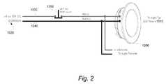
- FIG. 2is a schematic diagram of a tri-light (three color) LED fixture which includes the circuit arrangement depicted in used in FIG. 1 ;
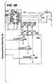
- FIGS. 3A and 3Bare circuit diagrams illustrating a specific example of circuitry schematically depicted in FIG. 1 .
- FIGS. 4A and 4Bare circuit diagrams illustrating a second specific example of circuitry which can be used in connection with the dual color arrangement.
- FIGS. 1 and 2illustrate, a so called tri-light assembly 1010 which is configured to produce three different colored light.
- the assembly 1010could, as noted above, also be arranged to produce two (a bi-light) or four (a quad-light) or five (penta-light) or more different colors.
- tri-lightis used for illustrative purposes only not limiting to the scope of the invention.
- the tri-light assembly 1010includes a housing 1200 (see FIG. 2 ) and receives power from a power source 1020 (9 to 30 VDC) via a switch 1250 .
- the housing 200has what shall be referred to as a power input 1210 . That is to say, a connection site/arrangement which allows the operatively electrical connection of the positive and negative power lines 1220 , 1240 that enable current to be supplied to the 1200 .
- the housing 1200floats (electrically) and is not grounded to anything. However, there will be instances wherein a ground can be established without the provision of wiring specifically for that purpose and that the housing can be grounded through an electrically conductive chassis or the like.
- the +9 to 30V DC input wire 1220 and a common wire 1240 connectionstreamlines the installation to two wires, making it a drop in replacement for most convenient light sources including the embodiments of the invention. In fact, it enables a mixture of single light and multi-color arrangements such as typified by the embodiments of the invention, with no need to change existing wiring/switches. Furthermore, applications whereas multiple colors of light would be traditionally excluded, may now without additional expense of wiring or installation become areas of multiple colors.
- the external power source 1020is electrically connected (via switch 1250 (also see FIG. 2 ) and the power input 1210 ) to a switching regulator 1030 , an input capacitor 1040 , and a 5V linear regulator 1042 .
- a microcontroller 1050is powered by the 5V linear regulator 1042 , in the illustrated manner, and the input capacitor being in parallel with the linear regulator 1042 .
- the microcontroller 1050is configured to respond to interruptions in the voltage from the power source 1020 and detect the operation of a switch 1250 which will described in more detail later.
- the 5V power supply 1042connects the input capacitor 1040 with the microcontroller 1050 .
- the interposition of the 5V power supplyenables the acceptance of a wide range of input voltages (i.e. 9 to 30 VDC) while providing a stable 5V source to power the microcontroller 1050 .
- the capacitor 1040is selected to maintain the supply of the 5V supply for a period of 3-4 seconds for example, and thus maintain the operation of the microcontroller 1050 for a period sufficient for an interruption to the power supply which lasts about 1 second (for example) to be detected by the microcontroller 1050 .
- the microcontroller 1050is alerted to the absence of power being supplied via line 1212 .
- the microcontroller 1050is electrically connected to a first field effect transistor (FET) 1100 , a second FET 1110 and a third FET 1120 .
- FETfield effect transistor
- Each of these FETcan be CMOS or PMOS.
- Each FET 1100 , 1110 , 1120controls the connection between a respective LED light source 1140 , 1150 , 1160 , and ground.
- the LED light sources 1140 , 1150 , 1160can be wired in series or in parallel. However, in given circumstances series wiring is preferred ensures equal distribution of current to each of the LEDs.
- the color of the first plurality of LED constituting the first LED light source 1140can be selected from at least white, white warm, green, blue or red and other colors.
- the color of the second LED light source 1150can be selected from at least white, white warm, green, blue or red and other colors.
- the color of the third LED light source 1160is selected from at least white, white warm, green, blue or red and other colors.
- the LED light source 1140 , 1150 , or 1160could consist of two different LEDs for example a blue and red LED, thus when a current is applied, a resultant mixed color will be displayed (i.e. pink).
- the microcontroller 1050 used in this embodiment of the present inventionis, merely by way of example, a low cost, eight pin microcontroller.
- the microcontroller 1050is arranged/programmed to respond to the voltage appearing on line 1212 to toggle from a state wherein voltages appearing on output ports/pins 1052 , 1054 and 1056 of the microcontroller 1050 all assume a zero level (no FET is grounded and there is no current flow through any of the LED light sources) to a state wherein voltage at port 1052 is high (FET 100 is rendered conductive, connects the LED light fixture 1142 to ground thus energizing the series of LED which comprise the light source). At this time, the voltage at ports 1054 and 1056 remain low. In response to the next short voltage interrupt, the voltage at port 1052 falls and that on port 1054 assumes a high level. The following interrupt induces the situation wherein the port 1056 is solely raised to a high level. Following this all ports return to their initial low levels in readiness for the next toggling.
- the switching regulator 1030is arranged to constantly supply the LED light sources with current and that the microcontroller 1050 simply renders a field effect transistor (FET) conductive to establish a ground connection thus completing a circuit, and therefore differs from the situation wherein the FET are driven in manner such that the FET switches on and off to control intensity.
- FETfield effect transistor
- this embodiment of that inventionis configured such that internal to the tri-light assembly 1010 it is the switching regulator 1030 that drives the LED light sources 1140 , 1150 , and 1160 , an input capacitor 1040 , a 5V power supply 1042 that powers the microcontroller 1050 , the microcontroller connected to the switching regulator 30 and three FETs 1100 , 1110 , and 1120 . These FETs are configured to selectively connect the LED light sources to ground, thus completing the circuit. The entire fixture is powered by power source 1020 , this power source supplying power to the 5V power supply 1042 as well as the switching regulator 1030 .
- the power supply 1042 as illustratedis a linear regulator just as the switching regulator 1030 is configured as a switching regulator, the topology whether linear or switching, whether buck, boost, sepic, buck-boost, etc. may vary depending on the application.
- the light sourcesare selectively illuminated with a constant voltage from the voltage source 1020 . That is to say, the switching regulator 1030 acts as a source of constant current for all of the LED light sources 1140 , 1150 , or 1160 , and the color illumination dependent on which FET 1100 , 1110 , or 1120 is rendered conductive by the microcontroller 1050 .
- a uservia a simple switch or relay, for example a toggle switch or momentary toggle switch, simply interrupts the supply of power from the power source 1020 for 1 second or less.
- a simple switch or relayfor example a toggle switch or momentary toggle switch
- the basic operationis as follows.
- a userbriefly (one second or less) disrupts power by using switch 1250 to signal the LED light assembly(s) to change color.
- the supply of power through a selected one of the LED light sources 1140 , 1150 and 1160is changed when the user disrupts power.
- the light color sequenceis configured by software is given embodiments is often, LED 1 , LED 2 , LED 3 , off, LED 1 , etc.
- the microcontroller 1050prior to changing the LED light output, shuts off the LED driver 1030 via a shutdown pin (see shutdown pin 7 in FIGS. 3A and 3B ), and closes the currently close to FET and closes the next and that power on the driver.
- FIGS. 3A and 3Ba specific wiring diagram for the Tri-Light assembly 1010 of FIG. 1 is illustrated.
- This arrangementincludes a switching regulator circuit 1410 (add L 1 , D 2 , and the other components to the right of the dotted region) having the switching regulator 1030 , a grouping of LEDs 1440 comprising the first LED light source 1140 , a second plurality of LEDs comprising the second LED light source 1150 and a third plurality of LED which comprising the third LED light source 1160 .
- An FET arrangement 1450includes the FETs 1100 , the second FET 1110 and the third FET 1120 , circuited as shown.
- a microcontroller circuit 1420 , a voltage regulator circuit 1430 including a voltage regulator 1435 and a 5V power supplyis circuited in the manner depicted.
- the switching regulator circuit 1410includes a switching regulator 1030 , a plurality of transistors and a plurality of capacitors and an inductor arranged in the illustrated manner.
- the switching regulatorwhich in this embodiment comprises part number LT3474, is available from the Linear Technology Corporation, Milpitas Calif. The teachings of the LT3474 datasheet are incorporated herein by reference.
- the switching regulator 1030is a fixed frequency step-down DC/DC converter and operates as a constant-current source. According to another embodiment of the invention, switching regulator 1030 provides a plurality of PWM circuitry.
- the PWM circuitryutilizes current mode PWM architecture and provides fast transient response and cycle-by-cycle current limiting.
- pin 4 VIN of switching regulator 1030supplies current to the switching regulator 1030 internal circuit and to the internal power switch.
- the pin 10 SHDN of switching regulator 1030is used to shut down the switching regulator and the internal bias circuits.
- the pin 10 SHDN of switching regulator 1030is electrically coupled to microcontroller 1050 Pin 7 .
- the switching regulator 1030is powered through pin 4 which is electrically coupled to Vin.
- the switching regulator 1030provides a high low signal to SHDN pin 10 which turns the driver on and off to changing colors of LED light sources 1140 , 1150 and 1160 .
- the LED 1440is such that the first LED light source 1140 includes at least a LED 1 and a LED 2 . Note that it is within the purview of the embodiments of the invention to use a single LED if so desired.
- the color of LED 1 and LED 2may be one of white, white warm, green, blue or red and other colors as noted above.
- the input of LED 1is electrically connected to the LED pin 3 of switching regulator 1030 .
- the output of LED 1is electrically coupled to the input of LED 2 .
- the output of LED 2is electrically connected to the first FET 100 .
- the second LED light source 1150includes at least LED 3 and LED 4 .
- the input of LED 3is electrically coupled to the LED pin of switching regulator 1030 .
- the output of LED 3is electrically connected to the input of LED 4 .
- the output of LED 4is electrically connected to the second of FET 1110 .
- the third LED light source 1160comprises LED 5 and LED 6 .
- the input of LED 5is electrically connected to the LED pin of switching regulator 1030 .
- the output of LED 5is electrically adapted to the input of LED 6 .
- the output of LED 6is electrically connected to a third FET 1120 .
- the microcontroller circuit 1420includes the microcontroller 1050 , a plurality of transistors and a plurality of capacitors organized and connected in the illustrated manner.
- the microcontroller 1050is, in this instance an 8-Pin, flashed based 8 bit CMOS microcontroller.
- This microcontrollerwhich can comprise part number PIC12F629, available from the Microchip Technology Inc., Chandler Ariz., although almost any properly programmed microcontroller or microcontroller can perform the software functions described herein.
- the teachings of the PIC12F629 datasheetare incorporated herein by reference.
- the microcontroller 50has internal and external oscillator options.
- the microcontroller 1050can utilize power saving sleep mode.
- the microcontroller 1050provides power-up time and oscillator start-up timer.
- the pin 7 of microcontroller 1050is electrically connected to switching regulator 1030 pin 10 .
- the pin 6 of microcontroller 1050is electrically coupled to a GATE of the first FET 1100 .
- the pin 2 of microcontroller 1050is electrically coupled to the GATE of the second FET 1110 .
- the pin 3 of microcontroller 1050is electrically connected to the GATE of a third plurality of FET 1120 .
- the pin 4 of microcontroller 1050is electrically connected to MSLR of 5V power supply 1042 .
- the microcontroller 1050is powered through pin 1 which is electrically coupled to a 5 voltage source.
- the pin 10 SHDN of switching regulator 1030provides high low signal to microcontroller 1050 pin 7 .
- the high low signal of switching regulator 1030will turn switching regulator 1030 on and off.
- the microcontroller 1050will receive on and off signal from switching regulator 1030 via microcontroller 1050 pin 7 .
- the on and off signalwill change color light color sequence as configured by software is OFF, LED 1 , LED 2 , LED 3 , OFF, LED 1 etc.
- the voltage regulator circuit 1430comprises a voltage regulator 1435 , a plurality of capacitors and a plurality of diodes configured in the illustrated manner.
- the voltage regulator 1435preferably part number LT3010, available from the Linear Technology Corporation, Milpitas Calif. The teachings of the LT3010 datasheet are incorporated herein by reference.
- the voltage regulator 1435is a high voltage, micro power low dropout linear regulator. Some illustrative examples of this embodiment comprise the ability to operate with very small output capacitors. Pin 1 of voltage regulator 1435 utilizes output supplies power to the load. A minimum output capacitor is required to prevent oscillations. Larger output capacitors will be required for applications with large transient loads to limit peak voltage transients. According to another embodiment of the preferred invention directed to the pin 2 of voltage regulator 1435 is the SENSE pin.
- Optimum regulationis obtained at the point where the SENSE pin is connected to the OUT pin of the regulator.
- the Pin 8 of voltage regulator 1435is the input pin.
- Some illustrative examples of this embodimentinclude power is supplied to the device through the input pin.
- a bypass capacitoris required on this pin if the device is more than six inches away from the main input filter capacitor.
- the 5V power supply 42is electrically coupled to the pin 4 of microcontroller 1050 .
- FIGS. 4A and 4Bdepict a circuit arrangement which can be used in connection with the embodiments of the present invention.
- this circuitcomprises: a 5 v logic supply; an open circuit voltage clamp; a current control loop; a hold-up supply; a de-bounce filter; a toggle circuit and a LED current switch; circuited in the illustrated manner.
- the toggle circuitis responsive to interrupts in the Vin voltage via the Zener diodes D 1 and D 6 .
- Capacitor C 6is arranged to maintain the operation of the toggle circuit for a predetermined short period to enable the toggling operation to implemented in response to the interrupt.
- the supply of current to the red and white LEDis controlled by the FET in the toggle circuit and the LED current switch.
- the FET in the LED switchare selectively rendered conductive by inputs which pass through the FET in the toggle circuit.
- the red and white LEDare selectively energized in accordance with which of the FET in the LED current switch is rendered conductive.
- the current control loopis circuited in this arrangement to provide a feedback control which ensures that a constant current is supplied to the each of the LED under all conditions.
- FIGS. 4A and 4B circuitdiffers in that the FET are not used to control ground as in the previous arrangements. Further, this particular arrangement is limited to only two colors—red and white. It is however, deemed within the purview of those skilled in the art when equipped with the preceding disclosure, to compile a circuit based on that which is illustrated in this figure, where more than two LED are provided and the toggling circuit appropriately changed to accommodate their selective energization.
Landscapes
- Circuit Arrangement For Electric Light Sources In General (AREA)
Abstract
Description
- 1) the switching regulator has no power available and thus none of the LEDs are illuminated;
- 2) the input capacitor has enough charge such that the 5V power supply is still live providing power to the microcontroller;
- 3) the microcontroller notes that the power source is gone for at least defined duration of time (thus does not change colors on a false alarm such as in response to spike in the power supply); and
- 4) once the power source comes back up, the microcontroller quickly shuts off the switching regulator (note that the micrcontroller has the switching regulator already shut off when the power is gone), via connection 48/32 the microcontroller then changes to the next FET as designated in the toggle control program and then turns back on the switching regulator such that which ever LEDs are connected to ground via their respective FET are illuminated.
Claims (30)
Priority Applications (2)
| Application Number | Priority Date | Filing Date | Title |
|---|---|---|---|
| US11/869,663US8013538B2 (en) | 2007-01-26 | 2007-10-09 | TRI-light |
| US13/198,513US8436553B2 (en) | 2007-01-26 | 2011-08-04 | Tri-light |
Applications Claiming Priority (2)
| Application Number | Priority Date | Filing Date | Title |
|---|---|---|---|
| US88686607P | 2007-01-26 | 2007-01-26 | |
| US11/869,663US8013538B2 (en) | 2007-01-26 | 2007-10-09 | TRI-light |
Related Child Applications (1)
| Application Number | Title | Priority Date | Filing Date |
|---|---|---|---|
| US13/198,513ContinuationUS8436553B2 (en) | 2007-01-26 | 2011-08-04 | Tri-light |
Publications (2)
| Publication Number | Publication Date |
|---|---|
| US20090195189A1 US20090195189A1 (en) | 2009-08-06 |
| US8013538B2true US8013538B2 (en) | 2011-09-06 |
Family
ID=40931024
Family Applications (2)
| Application Number | Title | Priority Date | Filing Date |
|---|---|---|---|
| US11/869,663Expired - Fee RelatedUS8013538B2 (en) | 2007-01-26 | 2007-10-09 | TRI-light |
| US13/198,513Expired - Fee RelatedUS8436553B2 (en) | 2007-01-26 | 2011-08-04 | Tri-light |
Family Applications After (1)
| Application Number | Title | Priority Date | Filing Date |
|---|---|---|---|
| US13/198,513Expired - Fee RelatedUS8436553B2 (en) | 2007-01-26 | 2011-08-04 | Tri-light |
Country Status (1)
| Country | Link |
|---|---|
| US (2) | US8013538B2 (en) |
Cited By (36)
| Publication number | Priority date | Publication date | Assignee | Title |
|---|---|---|---|---|
| US20100277086A1 (en)* | 2009-04-29 | 2010-11-04 | Hong Fu Jin Precision Industry (Shenzhen) Co., Ltd. | Circuit for driving led |
| US20100327764A1 (en)* | 2008-09-05 | 2010-12-30 | Knapp David J | Intelligent illumination device |
| US20110063214A1 (en)* | 2008-09-05 | 2011-03-17 | Knapp David J | Display and optical pointer systems and related methods |
| US20120242227A1 (en)* | 2011-03-22 | 2012-09-27 | Bob Miller | Lighting device and method of transitioning color outputs |
| US20130134905A1 (en)* | 2011-11-28 | 2013-05-30 | Marvell International Ltd. | Color mixing system with buck-boost and flyback topologies |
| US8886047B2 (en) | 2008-09-05 | 2014-11-11 | Ketra, Inc. | Optical communication device, method and system |
| US9146028B2 (en) | 2013-12-05 | 2015-09-29 | Ketra, Inc. | Linear LED illumination device with improved rotational hinge |
| US9155155B1 (en) | 2013-08-20 | 2015-10-06 | Ketra, Inc. | Overlapping measurement sequences for interference-resistant compensation in light emitting diode devices |
| US9237612B1 (en) | 2015-01-26 | 2016-01-12 | Ketra, Inc. | Illumination device and method for determining a target lumens that can be safely produced by an illumination device at a present temperature |
| US9237620B1 (en) | 2013-08-20 | 2016-01-12 | Ketra, Inc. | Illumination device and temperature compensation method |
| US9237623B1 (en) | 2015-01-26 | 2016-01-12 | Ketra, Inc. | Illumination device and method for determining a maximum lumens that can be safely produced by the illumination device to achieve a target chromaticity |
| US9247605B1 (en) | 2013-08-20 | 2016-01-26 | Ketra, Inc. | Interference-resistant compensation for illumination devices |
| US9276766B2 (en) | 2008-09-05 | 2016-03-01 | Ketra, Inc. | Display calibration systems and related methods |
| US9295112B2 (en) | 2008-09-05 | 2016-03-22 | Ketra, Inc. | Illumination devices and related systems and methods |
| US9332598B1 (en) | 2013-08-20 | 2016-05-03 | Ketra, Inc. | Interference-resistant compensation for illumination devices having multiple emitter modules |
| US9345097B1 (en) | 2013-08-20 | 2016-05-17 | Ketra, Inc. | Interference-resistant compensation for illumination devices using multiple series of measurement intervals |
| US9360174B2 (en) | 2013-12-05 | 2016-06-07 | Ketra, Inc. | Linear LED illumination device with improved color mixing |
| US9386668B2 (en) | 2010-09-30 | 2016-07-05 | Ketra, Inc. | Lighting control system |
| US9392660B2 (en) | 2014-08-28 | 2016-07-12 | Ketra, Inc. | LED illumination device and calibration method for accurately characterizing the emission LEDs and photodetector(s) included within the LED illumination device |
| US9392663B2 (en) | 2014-06-25 | 2016-07-12 | Ketra, Inc. | Illumination device and method for controlling an illumination device over changes in drive current and temperature |
| US9485813B1 (en) | 2015-01-26 | 2016-11-01 | Ketra, Inc. | Illumination device and method for avoiding an over-power or over-current condition in a power converter |
| US9510416B2 (en) | 2014-08-28 | 2016-11-29 | Ketra, Inc. | LED illumination device and method for accurately controlling the intensity and color point of the illumination device over time |
| US9557214B2 (en) | 2014-06-25 | 2017-01-31 | Ketra, Inc. | Illumination device and method for calibrating an illumination device over changes in temperature, drive current, and time |
| US9578724B1 (en) | 2013-08-20 | 2017-02-21 | Ketra, Inc. | Illumination device and method for avoiding flicker |
| US9651632B1 (en) | 2013-08-20 | 2017-05-16 | Ketra, Inc. | Illumination device and temperature calibration method |
| US9736903B2 (en) | 2014-06-25 | 2017-08-15 | Ketra, Inc. | Illumination device and method for calibrating and controlling an illumination device comprising a phosphor converted LED |
| US9736895B1 (en) | 2013-10-03 | 2017-08-15 | Ketra, Inc. | Color mixing optics for LED illumination device |
| US9769899B2 (en) | 2014-06-25 | 2017-09-19 | Ketra, Inc. | Illumination device and age compensation method |
| US10161786B2 (en) | 2014-06-25 | 2018-12-25 | Lutron Ketra, Llc | Emitter module for an LED illumination device |
| US10210750B2 (en) | 2011-09-13 | 2019-02-19 | Lutron Electronics Co., Inc. | System and method of extending the communication range in a visible light communication system |
| US10278254B2 (en) | 2016-12-02 | 2019-04-30 | Sterno Home Inc. | Illumination system with color-changing lights |
| USRE48955E1 (en) | 2013-08-20 | 2022-03-01 | Lutron Technology Company Llc | Interference-resistant compensation for illumination devices having multiple emitter modules |
| USRE48956E1 (en) | 2013-08-20 | 2022-03-01 | Lutron Technology Company Llc | Interference-resistant compensation for illumination devices using multiple series of measurement intervals |
| US11272599B1 (en) | 2018-06-22 | 2022-03-08 | Lutron Technology Company Llc | Calibration procedure for a light-emitting diode light source |
| USRE49454E1 (en) | 2010-09-30 | 2023-03-07 | Lutron Technology Company Llc | Lighting control system |
| USRE50468E1 (en) | 2008-09-05 | 2025-06-24 | Lutron Technology Company Llc | Intelligent illumination device |
Families Citing this family (50)
| Publication number | Priority date | Publication date | Assignee | Title |
|---|---|---|---|---|
| US9070850B2 (en) | 2007-10-31 | 2015-06-30 | Cree, Inc. | Light emitting diode package and method for fabricating same |
| US7821023B2 (en) | 2005-01-10 | 2010-10-26 | Cree, Inc. | Solid state lighting component |
| US9793247B2 (en) | 2005-01-10 | 2017-10-17 | Cree, Inc. | Solid state lighting component |
| US9335006B2 (en) | 2006-04-18 | 2016-05-10 | Cree, Inc. | Saturated yellow phosphor converted LED and blue converted red LED |
| US10295147B2 (en)* | 2006-11-09 | 2019-05-21 | Cree, Inc. | LED array and method for fabricating same |
| TWM345193U (en)* | 2008-03-13 | 2008-11-21 | Ming-Yue Jiang | Energy-saving white light actuator having renewable power |
| US9425172B2 (en) | 2008-10-24 | 2016-08-23 | Cree, Inc. | Light emitter array |
| DE102009018868B4 (en)* | 2009-04-24 | 2024-04-25 | Ledvance Gmbh | LED retrofit lamp and method for operating an LED retrofit lamp |
| US8427063B2 (en)* | 2009-07-29 | 2013-04-23 | Vektrex Electronic Systems, Inc. | Multicolor LED sequencer |
| US8598809B2 (en)* | 2009-08-19 | 2013-12-03 | Cree, Inc. | White light color changing solid state lighting and methods |
| WO2011048214A1 (en)* | 2009-10-23 | 2011-04-28 | Tridonic Gmbh & Co Kg | Operation of an led luminaire having a variable spectrum |
| GB2476466A (en)* | 2009-12-22 | 2011-06-29 | Ritelite Systems Ltd | Battery monitor for light. |
| US9468070B2 (en) | 2010-02-16 | 2016-10-11 | Cree Inc. | Color control of light emitting devices and applications thereof |
| US9482397B2 (en) | 2010-03-17 | 2016-11-01 | Once Innovations, Inc. | Light sources adapted to spectral sensitivity of diurnal avians and humans |
| KR101163420B1 (en)* | 2010-04-21 | 2012-07-13 | 서운수 | A control circuit for automatic darkening welding helmet |
| KR101980724B1 (en)* | 2010-08-05 | 2019-05-21 | 온세미컨덕터코리아 주식회사 | Led emitting device and driving method thereof |
| US9786811B2 (en) | 2011-02-04 | 2017-10-10 | Cree, Inc. | Tilted emission LED array |
| US20120267953A1 (en)* | 2011-04-19 | 2012-10-25 | Doyle Kevin A | Apparatus and method for controlling and supplying power to electrical devices in high risk environments |
| US20120274233A1 (en)* | 2011-04-27 | 2012-11-01 | Sequoia Microelectronics Corporation | Constant current led driver |
| AU2012100729A4 (en)* | 2011-05-25 | 2012-06-28 | QU, Feng | LED Decorative Light |
| US20140312776A1 (en)* | 2011-06-24 | 2014-10-23 | Planet System Co., Ltd. | Dimming led lighting system |
| US10842016B2 (en) | 2011-07-06 | 2020-11-17 | Cree, Inc. | Compact optically efficient solid state light source with integrated thermal management |
| USD700584S1 (en) | 2011-07-06 | 2014-03-04 | Cree, Inc. | LED component |
| GB2498371B (en)* | 2012-01-12 | 2016-09-14 | Tridonic Gmbh & Co Kg | Lamp controller |
| US8816591B2 (en)* | 2012-05-26 | 2014-08-26 | Vastview Technology Inc. | Methods and apparatus for segmenting and driving LED-based lighting units |
| US11140879B2 (en)* | 2012-12-11 | 2021-10-12 | Signify North America Corporation | Methods for controlling sex of oviparous embryos using light sources |
| CN105493634B (en) | 2013-08-02 | 2019-02-01 | 万斯创新公司 | System and method for lighting livestock |
| US20160323960A1 (en)* | 2014-01-07 | 2016-11-03 | Once Innovations, Inc. | Dc led agricultural lighting assembly |
| US10206378B2 (en) | 2014-01-07 | 2019-02-19 | Once Innovations, Inc. | System and method of enhancing swine reproduction |
| US9247603B2 (en) | 2014-02-11 | 2016-01-26 | Once Innovations, Inc. | Shunt regulator for spectral shift controlled light source |
| US9752761B2 (en) | 2014-07-16 | 2017-09-05 | Telebrands Corp. | Landscape light |
| USD773707S1 (en) | 2014-10-30 | 2016-12-06 | Telebrands Corp. | Landscape light |
| USD766484S1 (en) | 2015-05-11 | 2016-09-13 | Telebrands Corp. | Light projector |
| USD778478S1 (en) | 2015-05-11 | 2017-02-07 | Telebrands Corp. | Light projector |
| USD766483S1 (en) | 2015-05-11 | 2016-09-13 | Telebrands Corp. | Light projector |
| USD816890S1 (en) | 2015-05-11 | 2018-05-01 | Telebrands Corp. | Light projector |
| USD824066S1 (en) | 2015-05-11 | 2018-07-24 | Telebrands Corp. | Light projector |
| US9458994B1 (en) | 2015-12-03 | 2016-10-04 | Telebrands Corp. | Decorative lighting apparatus having two laser light sources and a switch |
| US9879847B2 (en) | 2015-12-03 | 2018-01-30 | Telebrands Corp. | Decorative lighting apparatus having two laser light sources |
| US9546775B1 (en) | 2015-12-03 | 2017-01-17 | Telebrands Corp. | Decorative lighting apparatus having two laser light sources |
| US9562673B1 (en) | 2015-12-03 | 2017-02-07 | Telebrands Corp. | Decorative lighting apparatus having an attenuation assembly |
| WO2017139589A2 (en) | 2016-02-10 | 2017-08-17 | Hubbell Incorporated | Toggle control for lighting system |
| US10772172B2 (en) | 2016-03-29 | 2020-09-08 | Signify North America Corporation | System and method of illuminating livestock |
| USD798484S1 (en) | 2016-09-29 | 2017-09-26 | Telebrands Corp. | Landscape light |
| USD797975S1 (en) | 2016-09-29 | 2017-09-19 | Telebrands Corp. | Landscape light |
| US10314125B2 (en) | 2016-09-30 | 2019-06-04 | Once Innovations, Inc. | Dimmable analog AC circuit |
| US11234319B2 (en) | 2017-02-14 | 2022-01-25 | Hubbell Incorporated | Backup power source and control for power over ethernet light sources |
| US10568187B1 (en)* | 2018-03-23 | 2020-02-18 | Chien Luen Industries, Co., Ltd., Inc. | Color changing LED (light emitting diode) module for ceiling fans |
| US10980094B1 (en)* | 2020-06-24 | 2021-04-13 | Yen-Chiu Chang | Power supply apparatus for string light |
| US11617245B2 (en)* | 2020-08-11 | 2023-03-28 | Abl Ip Holding Llc | LED driver with selectable lumen and CCT |
Citations (19)
| Publication number | Priority date | Publication date | Assignee | Title |
|---|---|---|---|---|
| US5343375A (en) | 1993-01-28 | 1994-08-30 | H. Koch & Sons Company | Emergency egress illuminator and marker light strip |
| US5607227A (en) | 1993-08-27 | 1997-03-04 | Sanyo Electric Co., Ltd. | Linear light source |
| US5785418A (en) | 1996-06-27 | 1998-07-28 | Hochstein; Peter A. | Thermally protected LED array |
| US5918962A (en) | 1993-06-16 | 1999-07-06 | Tivoli Industries, Inc. | Dual step light and aisle indicator apparatus |
| US6183104B1 (en) | 1998-02-18 | 2001-02-06 | Dennis Ferrara | Decorative lighting system |
| US6361186B1 (en) | 2000-08-02 | 2002-03-26 | Lektron Industrial Supply, Inc. | Simulated neon light using led's |
| WO2003017733A1 (en) | 2001-08-14 | 2003-02-27 | Microchip Technology Incorporated | Multiple master digital addressable lighting interface (dali) system, method and apparatus |
| US6561690B2 (en) | 2000-08-22 | 2003-05-13 | Koninklijke Philips Electronics N.V. | Luminaire based on the light emission of light-emitting diodes |
| US20030210546A1 (en) | 2002-05-13 | 2003-11-13 | Unity Opto Technology Co., Ltd. | Energy efficient tubular light |
| US20030223235A1 (en) | 2002-06-03 | 2003-12-04 | Ferenc Mohacsi | LED accent lighting units |
| US6796680B1 (en) | 2000-01-28 | 2004-09-28 | Lumileds Lighting U.S., Llc | Strip lighting |
| US6880952B2 (en) | 2002-03-18 | 2005-04-19 | Wintriss Engineering Corporation | Extensible linear light emitting diode illumination source |
| US6967448B2 (en)* | 1997-08-26 | 2005-11-22 | Color Kinetics, Incorporated | Methods and apparatus for controlling illumination |
| US7159997B2 (en) | 2004-12-30 | 2007-01-09 | Lo Lighting | Linear lighting apparatus with increased light-transmission efficiency |
| EP1760392A1 (en) | 2005-08-29 | 2007-03-07 | Patent-Treuhand-Gesellschaft für elektrische Glühlampen mbH | A mounting structure for LED lighting systems |
| US7213941B2 (en) | 2004-04-14 | 2007-05-08 | Sloanled, Inc. | Flexible perimeter lighting apparatus |
| US7274160B2 (en)* | 1997-08-26 | 2007-09-25 | Color Kinetics Incorporated | Multicolored lighting method and apparatus |
| US7358679B2 (en)* | 2002-05-09 | 2008-04-15 | Philips Solid-State Lighting Solutions, Inc. | Dimmable LED-based MR16 lighting apparatus and methods |
| US7598686B2 (en)* | 1997-12-17 | 2009-10-06 | Philips Solid-State Lighting Solutions, Inc. | Organic light emitting diode methods and apparatus |
Family Cites Families (278)
| Publication number | Priority date | Publication date | Assignee | Title |
|---|---|---|---|---|
| DE2652970C3 (en) | 1976-11-22 | 1979-09-06 | Hartwig Ing.(Grad.) 2409 Scharbeutz Beyersdorf | Ionization fire detectors |
| JPS556687A (en) | 1978-06-29 | 1980-01-18 | Handotai Kenkyu Shinkokai | Traffic use display |
| US4449186A (en) | 1981-10-15 | 1984-05-15 | Cubic Western Data | Touch panel passenger self-ticketing system |
| US5264997A (en) | 1992-03-04 | 1993-11-23 | Dominion Automotive Industries Corp. | Sealed, inductively powered lamp assembly |
| JP3183078B2 (en) | 1994-02-28 | 2001-07-03 | 三菱電機株式会社 | Control signal generation circuit, automatic gain control circuit using the same, receiver using the same, and communication system using the same |
| US5561346A (en) | 1994-08-10 | 1996-10-01 | Byrne; David J. | LED lamp construction |
| US5465199A (en) | 1994-08-19 | 1995-11-07 | Sea Gull Lighting | System for attaching trim to lamp housing |
| US6253530B1 (en) | 1995-09-27 | 2001-07-03 | Tracy Price | Structural honeycomb panel building system |
| EP1007880A4 (en) | 1996-06-10 | 2001-05-16 | Tenebraex Corp | Apparatus and methods for improved architectural lighting fixtures |
| US5803579A (en) | 1996-06-13 | 1998-09-08 | Gentex Corporation | Illuminator assembly incorporating light emitting diodes |
| US5909429A (en) | 1996-09-03 | 1999-06-01 | Philips Electronics North America Corporation | Method for installing a wireless network which transmits node addresses directly from a wireless installation device to the nodes without using the wireless network |
| CN1105852C (en) | 1996-10-16 | 2003-04-16 | 皇家菲利浦电子有限公司 | Signal lamp with LEDS |
| US5783909A (en) | 1997-01-10 | 1998-07-21 | Relume Corporation | Maintaining LED luminous intensity |
| TW330233B (en) | 1997-01-23 | 1998-04-21 | Philips Eloctronics N V | Luminary |
| CN1192682C (en) | 1997-08-01 | 2005-03-09 | 皇家菲利浦电子有限公司 | Circuit arrangement, and signaling light provided with circuit arrangement |
| DE69816958C5 (en) | 1997-08-01 | 2019-05-23 | Koninklijke Philips N.V. | CIRCUIT ARRANGEMENT WITH DIGITAL SIGNAL LIGHT |
| JP2001501362A (en) | 1997-08-01 | 2001-01-30 | コーニンクレッカ フィリップス エレクトロニクス エヌ ヴィ | Multi-resonant DC-DC converter with full-wave rectification means |
| US7242152B2 (en) | 1997-08-26 | 2007-07-10 | Color Kinetics Incorporated | Systems and methods of controlling light systems |
| US6548967B1 (en) | 1997-08-26 | 2003-04-15 | Color Kinetics, Inc. | Universal lighting network methods and systems |
| US7038398B1 (en) | 1997-08-26 | 2006-05-02 | Color Kinetics, Incorporated | Kinetic illumination system and methods |
| US7186003B2 (en) | 1997-08-26 | 2007-03-06 | Color Kinetics Incorporated | Light-emitting diode based products |
| US6016038A (en) | 1997-08-26 | 2000-01-18 | Color Kinetics, Inc. | Multicolored LED lighting method and apparatus |
| US7014336B1 (en) | 1999-11-18 | 2006-03-21 | Color Kinetics Incorporated | Systems and methods for generating and modulating illumination conditions |
| US6975079B2 (en) | 1997-08-26 | 2005-12-13 | Color Kinetics Incorporated | Systems and methods for controlling illumination sources |
| US6528954B1 (en) | 1997-08-26 | 2003-03-04 | Color Kinetics Incorporated | Smart light bulb |
| US6720745B2 (en) | 1997-08-26 | 2004-04-13 | Color Kinetics, Incorporated | Data delivery track |
| US6292901B1 (en) | 1997-08-26 | 2001-09-18 | Color Kinetics Incorporated | Power/data protocol |
| US6777891B2 (en) | 1997-08-26 | 2004-08-17 | Color Kinetics, Incorporated | Methods and apparatus for controlling devices in a networked lighting system |
| US7064498B2 (en) | 1997-08-26 | 2006-06-20 | Color Kinetics Incorporated | Light-emitting diode based products |
| US20070086912A1 (en) | 1997-08-26 | 2007-04-19 | Color Kinetics Incorporated | Ultraviolet light emitting diode systems and methods |
| US20030133292A1 (en) | 1999-11-18 | 2003-07-17 | Mueller George G. | Methods and apparatus for generating and modulating white light illumination conditions |
| US7139617B1 (en) | 1999-07-14 | 2006-11-21 | Color Kinetics Incorporated | Systems and methods for authoring lighting sequences |
| US7113541B1 (en) | 1997-08-26 | 2006-09-26 | Color Kinetics Incorporated | Method for software driven generation of multiple simultaneous high speed pulse width modulated signals |
| US6965205B2 (en) | 1997-08-26 | 2005-11-15 | Color Kinetics Incorporated | Light emitting diode based products |
| US6211626B1 (en) | 1997-08-26 | 2001-04-03 | Color Kinetics, Incorporated | Illumination components |
| US7161313B2 (en) | 1997-08-26 | 2007-01-09 | Color Kinetics Incorporated | Light emitting diode based products |
| US7231060B2 (en) | 1997-08-26 | 2007-06-12 | Color Kinetics Incorporated | Systems and methods of generating control signals |
| US7353071B2 (en) | 1999-07-14 | 2008-04-01 | Philips Solid-State Lighting Solutions, Inc. | Method and apparatus for authoring and playing back lighting sequences |
| US20020113555A1 (en) | 1997-08-26 | 2002-08-22 | Color Kinetics, Inc. | Lighting entertainment system |
| US7352339B2 (en) | 1997-08-26 | 2008-04-01 | Philips Solid-State Lighting Solutions | Diffuse illumination systems and methods |
| US6608453B2 (en) | 1997-08-26 | 2003-08-19 | Color Kinetics Incorporated | Methods and apparatus for controlling devices in a networked lighting system |
| US20040052076A1 (en) | 1997-08-26 | 2004-03-18 | Mueller George G. | Controlled lighting methods and apparatus |
| US6459919B1 (en) | 1997-08-26 | 2002-10-01 | Color Kinetics, Incorporated | Precision illumination methods and systems |
| US20020074559A1 (en) | 1997-08-26 | 2002-06-20 | Dowling Kevin J. | Ultraviolet light emitting diode systems and methods |
| US7132804B2 (en) | 1997-12-17 | 2006-11-07 | Color Kinetics Incorporated | Data delivery track |
| US6236331B1 (en) | 1998-02-20 | 2001-05-22 | Newled Technologies Inc. | LED traffic light intensity controller |
| US6095661A (en) | 1998-03-19 | 2000-08-01 | Ppt Vision, Inc. | Method and apparatus for an L.E.D. flashlight |
| DE69912391T2 (en) | 1998-07-01 | 2004-08-19 | Koninklijke Philips Electronics N.V. | CIRCUIT ARRANGEMENT AND SIGNAL LIGHT THEREFORE |
| DE69912623T2 (en) | 1998-09-04 | 2004-09-23 | Wynne Willson Gottelier Ltd., Tunbridge Wells | DEVICE AND METHOD FOR PROVIDING A LINEAR EFFECT |
| TW417842U (en) | 1998-09-28 | 2001-01-01 | Koninkl Philips Electronics Nv | Lighting system |
| KR100702273B1 (en) | 1998-09-28 | 2007-03-30 | 코닌클리즈케 필립스 일렉트로닉스 엔.브이. | Lighting system |
| AUPP729298A0 (en) | 1998-11-24 | 1998-12-17 | Showers International Pty Ltd | Housing and mounting system for a strip lighting device |
| US6495964B1 (en) | 1998-12-18 | 2002-12-17 | Koninklijke Philips Electronics N.V. | LED luminaire with electrically adjusted color balance using photodetector |
| US6127783A (en) | 1998-12-18 | 2000-10-03 | Philips Electronics North America Corp. | LED luminaire with electronically adjusted color balance |
| US6445139B1 (en) | 1998-12-18 | 2002-09-03 | Koninklijke Philips Electronics N.V. | Led luminaire with electrically adjusted color balance |
| DE19904933C1 (en) | 1999-02-06 | 2000-04-13 | Wila Leuchten Ag Sevelen | Ceiling light fitting has annular tubular lamp enclosing space for receiving housing of additional installation device |
| US6299329B1 (en) | 1999-02-23 | 2001-10-09 | Hewlett-Packard Company | Illumination source for a scanner having a plurality of solid state lamps and a related method |
| CN1319415C (en) | 1999-07-07 | 2007-05-30 | 皇家菲利浦电子有限公司 | Flyback converter as LED driver |
| US6296612B1 (en) | 1999-07-09 | 2001-10-02 | General Electric Company | Method and apparatus for adaptive wall filtering in spectral Doppler ultrasound imaging |
| US7233831B2 (en) | 1999-07-14 | 2007-06-19 | Color Kinetics Incorporated | Systems and methods for controlling programmable lighting systems |
| US20080140231A1 (en) | 1999-07-14 | 2008-06-12 | Philips Solid-State Lighting Solutions, Inc. | Methods and apparatus for authoring and playing back lighting sequences |
| US6340864B1 (en) | 1999-08-10 | 2002-01-22 | Philips Electronics North America Corporation | Lighting control system including a wireless remote sensor |
| US6157093A (en) | 1999-09-27 | 2000-12-05 | Philips Electronics North America Corporation | Modular master-slave power supply controller |
| EP1224843A1 (en) | 1999-09-29 | 2002-07-24 | Color Kinetics Incorporated | Systems and methods for calibrating light output by light-emitting diodes |
| US6249088B1 (en) | 1999-11-01 | 2001-06-19 | Philips Electronics North America Corporation | Three-dimensional lattice structure based led array for illumination |
| US6201353B1 (en) | 1999-11-01 | 2001-03-13 | Philips Electronics North America Corporation | LED array employing a lattice relationship |
| US6194839B1 (en) | 1999-11-01 | 2001-02-27 | Philips Electronics North America Corporation | Lattice structure based LED array for illumination |
| US6513949B1 (en) | 1999-12-02 | 2003-02-04 | Koninklijke Philips Electronics N.V. | LED/phosphor-LED hybrid lighting systems |
| JP4731085B2 (en) | 2000-02-03 | 2011-07-20 | コーニンクレッカ フィリップス エレクトロニクス エヌ ヴィ | Power supply assembly for LED lighting module |
| US6288497B1 (en) | 2000-03-24 | 2001-09-11 | Philips Electronics North America Corporation | Matrix structure based LED array for illumination |
| US6498440B2 (en)* | 2000-03-27 | 2002-12-24 | Gentex Corporation | Lamp assembly incorporating optical feedback |
| PT1422975E (en) | 2000-04-24 | 2010-07-09 | Philips Solid State Lighting | Light-emitting diode based product |
| US7550935B2 (en) | 2000-04-24 | 2009-06-23 | Philips Solid-State Lighting Solutions, Inc | Methods and apparatus for downloading lighting programs |
| EP1295515B1 (en) | 2000-06-21 | 2011-12-28 | Philips Solid-State Lighting Solutions, Inc. | Method and apparatus for controlling a lighting system in response to an audio input |
| US20050275626A1 (en) | 2000-06-21 | 2005-12-15 | Color Kinetics Incorporated | Entertainment lighting system |
| US7502034B2 (en) | 2003-11-20 | 2009-03-10 | Phillips Solid-State Lighting Solutions, Inc. | Light system manager |
| US7202613B2 (en) | 2001-05-30 | 2007-04-10 | Color Kinetics Incorporated | Controlled lighting methods and apparatus |
| WO2002011497A1 (en) | 2000-07-27 | 2002-02-07 | Color Kinetics Incorporated | Lighting control using speech recognition |
| US7161556B2 (en) | 2000-08-07 | 2007-01-09 | Color Kinetics Incorporated | Systems and methods for programming illumination devices |
| AU2001285408A1 (en) | 2000-08-07 | 2002-02-18 | Color Kinetics Incorporated | Automatic configuration systems and methods for lighting and other applications |
| US6636003B2 (en) | 2000-09-06 | 2003-10-21 | Spectrum Kinetics | Apparatus and method for adjusting the color temperature of white semiconduct or light emitters |
| US6507158B1 (en) | 2000-11-15 | 2003-01-14 | Koninkljke Philips Electronics N.V. | Protocol enhancement for lighting control networks and communications interface for same |
| US6441558B1 (en) | 2000-12-07 | 2002-08-27 | Koninklijke Philips Electronics N.V. | White LED luminary light control system |
| US6411046B1 (en) | 2000-12-27 | 2002-06-25 | Koninklijke Philips Electronics, N. V. | Effective modeling of CIE xy coordinates for a plurality of LEDs for white LED light control |
| US7071762B2 (en) | 2001-01-31 | 2006-07-04 | Koninklijke Philips Electronics N.V. | Supply assembly for a led lighting module |
| US6831569B2 (en) | 2001-03-08 | 2004-12-14 | Koninklijke Philips Electronics N.V. | Method and system for assigning and binding a network address of a ballast |
| US7038399B2 (en) | 2001-03-13 | 2006-05-02 | Color Kinetics Incorporated | Methods and apparatus for providing power to lighting devices |
| US6801003B2 (en) | 2001-03-13 | 2004-10-05 | Color Kinetics, Incorporated | Systems and methods for synchronizing lighting effects |
| US6510995B2 (en) | 2001-03-16 | 2003-01-28 | Koninklijke Philips Electronics N.V. | RGB LED based light driver using microprocessor controlled AC distributed power system |
| US6384545B1 (en) | 2001-03-19 | 2002-05-07 | Ee Theow Lau | Lighting controller |
| US6507159B2 (en) | 2001-03-29 | 2003-01-14 | Koninklijke Philips Electronics N.V. | Controlling method and system for RGB based LED luminary |
| US6576881B2 (en) | 2001-04-06 | 2003-06-10 | Koninklijke Philips Electronics N.V. | Method and system for controlling a light source |
| US20020145392A1 (en)* | 2001-04-09 | 2002-10-10 | Hair James M. | Led lighting string |
| US6992803B2 (en) | 2001-05-08 | 2006-01-31 | Koninklijke Philips Electronics N.V. | RGB primary color point identification system and method |
| US6577512B2 (en) | 2001-05-25 | 2003-06-10 | Koninklijke Philips Electronics N.V. | Power supply for LEDs |
| US7598684B2 (en) | 2001-05-30 | 2009-10-06 | Philips Solid-State Lighting Solutions, Inc. | Methods and apparatus for controlling devices in a networked lighting system |
| US6741351B2 (en) | 2001-06-07 | 2004-05-25 | Koninklijke Philips Electronics N.V. | LED luminaire with light sensor configurations for optical feedback |
| US6639368B2 (en) | 2001-07-02 | 2003-10-28 | Koninklijke Philips Electronics N.V. | Programmable PWM module for controlling a ballast |
| DE60211710T2 (en) | 2001-07-19 | 2007-05-16 | Lumileds Lighting U.S., LLC, San Jose | LED CIRCUIT |
| ATE326826T1 (en) | 2001-07-19 | 2006-06-15 | Lumileds Lighting Llc | LED CIRCUIT |
| US6617795B2 (en) | 2001-07-26 | 2003-09-09 | Koninklijke Philips Electronics N.V. | Multichip LED package with in-package quantitative and spectral sensing capability and digital signal output |
| US6489731B1 (en) | 2001-07-27 | 2002-12-03 | Koninklijke Philips Electronics N.V. | Power supply and/or ballast system controlled by desired load power spectrum |
| US6621235B2 (en) | 2001-08-03 | 2003-09-16 | Koninklijke Philips Electronics N.V. | Integrated LED driving device with current sharing for multiple LED strings |
| US6734639B2 (en) | 2001-08-15 | 2004-05-11 | Koninklijke Philips Electronics N.V. | Sample and hold method to achieve square-wave PWM current source for light emitting diode arrays |
| US7323676B2 (en) | 2001-09-11 | 2008-01-29 | Lumileds Lighting Us, Llc. | Color photosensor with color filters and subtraction unit |
| US7358929B2 (en) | 2001-09-17 | 2008-04-15 | Philips Solid-State Lighting Solutions, Inc. | Tile lighting methods and systems |
| US6596977B2 (en) | 2001-10-05 | 2003-07-22 | Koninklijke Philips Electronics N.V. | Average light sensing for PWM control of RGB LED based white light luminaries |
| US6630801B2 (en) | 2001-10-22 | 2003-10-07 | Lümileds USA | Method and apparatus for sensing the color point of an RGB LED white luminary using photodiodes |
| US6586890B2 (en) | 2001-12-05 | 2003-07-01 | Koninklijke Philips Electronics N.V. | LED driver circuit with PWM output |
| US6552495B1 (en) | 2001-12-19 | 2003-04-22 | Koninklijke Philips Electronics N.V. | Adaptive control system and method with spatial uniform color metric for RGB LED based white light illumination |
| US6932477B2 (en) | 2001-12-21 | 2005-08-23 | Koninklijke Philips Electronics N.V. | Apparatus for providing multi-spectral light for an image projection system |
| US6724159B2 (en) | 2001-12-27 | 2004-04-20 | Koninklijke Philips Electronics N.V. | Method and apparatus for controlling lighting based on user behavior |
| US6853150B2 (en) | 2001-12-28 | 2005-02-08 | Koninklijke Philips Electronics N.V. | Light emitting diode driver |
| EP1479270B1 (en) | 2002-02-14 | 2006-07-05 | Koninklijke Philips Electronics N.V. | Switching device for driving a led array |
| US6859644B2 (en) | 2002-03-13 | 2005-02-22 | Koninklijke Philips Electronics N.V. | Initialization of wireless-controlled lighting systems |
| US6998594B2 (en) | 2002-06-25 | 2006-02-14 | Koninklijke Philips Electronics N.V. | Method for maintaining light characteristics from a multi-chip LED package |
| DE10330135A1 (en) | 2002-07-10 | 2004-01-22 | LumiLeds Lighting, U.S., LLC, San Jose | circuitry |
| DK1535495T3 (en) | 2002-08-28 | 2010-10-11 | Philips Solid State Lighting | Methods and systems for illumination of surroundings |
| US7300192B2 (en) | 2002-10-03 | 2007-11-27 | Color Kinetics Incorporated | Methods and apparatus for illuminating environments |
| US6796686B2 (en) | 2002-10-04 | 2004-09-28 | Tir Systems Ltd. | Color-corrected hollow prismatic light guide luminaire |
| US6930452B2 (en) | 2002-10-14 | 2005-08-16 | Lumileds Lighting U.S., Llc | Circuit arrangement |
| US7490957B2 (en) | 2002-11-19 | 2009-02-17 | Denovo Lighting, L.L.C. | Power controls with photosensor for tube mounted LEDs with ballast |
| US6853151B2 (en) | 2002-11-19 | 2005-02-08 | Denovo Lighting, Llc | LED retrofit lamp |
| US7507001B2 (en) | 2002-11-19 | 2009-03-24 | Denovo Lighting, Llc | Retrofit LED lamp for fluorescent fixtures without ballast |
| US6762562B2 (en) | 2002-11-19 | 2004-07-13 | Denovo Lighting, Llc | Tubular housing with light emitting diodes |
| US7067992B2 (en) | 2002-11-19 | 2006-06-27 | Denovo Lighting, Llc | Power controls for tube mounted LEDs with ballast |
| JP2006508504A (en) | 2002-11-27 | 2006-03-09 | コーニンクレッカ フィリップス エレクトロニクス エヌ ヴィ | A luminaire that gives a controllable intensity distribution to the output beam |
| DE10356608B4 (en) | 2002-12-03 | 2017-09-28 | Philips Lighting North America Corporation | Lighting arrangement and liquid crystal display |
| FI2964000T3 (en) | 2002-12-19 | 2023-01-13 | Led driver | |
| JP4818610B2 (en) | 2002-12-20 | 2011-11-16 | コーニンクレッカ フィリップス エレクトロニクス エヌ ヴィ | Method and apparatus for sensing light emitted from a plurality of light sources |
| CN100493280C (en) | 2002-12-26 | 2009-05-27 | 皇家飞利浦电子股份有限公司 | Color temperature correction of phosphor converted light emitting diodes |
| DE60326392D1 (en) | 2002-12-26 | 2009-04-09 | Koninkl Philips Electronics Nv | PWM LED CONTROLLER WITH SCAN AND HOLD FUNCTION |
| WO2004100624A2 (en) | 2003-05-05 | 2004-11-18 | Color Kinetics, Inc. | Lighting methods and systems |
| CN100531486C (en) | 2003-05-07 | 2009-08-19 | 皇家飞利浦电子股份有限公司 | Current control method and circuit for light emitting diodes |
| US7358961B2 (en) | 2003-05-07 | 2008-04-15 | Koninklijke Philips Electronics N.V. | User interface for controlling light emitting diodes |
| EP1637015B1 (en) | 2003-06-10 | 2014-12-03 | Koninklijke Philips N.V. | Light output modulation for data transmission |
| WO2005008127A1 (en) | 2003-07-22 | 2005-01-27 | Tir Systems Ltd. | System and method for the diffusion of illumination produced by discrete light sources |
| CN100544531C (en) | 2003-07-23 | 2009-09-23 | 皇家飞利浦电子股份有限公司 | Control system for a lighting device including discrete light sources |
| TWI329724B (en) | 2003-09-09 | 2010-09-01 | Koninkl Philips Electronics Nv | Integrated lamp with feedback and wireless control |
| CN1602132A (en) | 2003-09-24 | 2005-03-30 | 皇家飞利浦电子股份有限公司 | System and method of controlling luminous device |
| US20070063658A1 (en) | 2003-10-24 | 2007-03-22 | Koninklijke Philips Electronics N.V. | Ballast |
| US7573729B2 (en) | 2003-11-13 | 2009-08-11 | Koninklijke Philips Electronics N.V. | Resonant power LED control circuit with brightness and color control |
| US7202641B2 (en) | 2003-12-12 | 2007-04-10 | Philips Lumileds Lighting Company, Llc | DC-to-DC converter |
| EP1711739A4 (en) | 2004-01-28 | 2008-07-23 | Tir Technology Lp | LUMINAIRE DIRECTLY VISIBLE |
| US20060221606A1 (en) | 2004-03-15 | 2006-10-05 | Color Kinetics Incorporated | Led-based lighting retrofit subassembly apparatus |
| EP1754121A4 (en) | 2004-03-15 | 2014-02-12 | Philips Solid State Lighting | METHODS AND SYSTEMS FOR PROVIDING LIGHTING SYSTEMS |
| US7354172B2 (en) | 2004-03-15 | 2008-04-08 | Philips Solid-State Lighting Solutions, Inc. | Methods and apparatus for controlled lighting based on a reference gamut |
| EP3589081B1 (en) | 2004-03-15 | 2024-02-21 | Signify North America Corporation | Power control methods and apparatus |
| US7515128B2 (en) | 2004-03-15 | 2009-04-07 | Philips Solid-State Lighting Solutions, Inc. | Methods and apparatus for providing luminance compensation |
| TW200602585A (en) | 2004-03-16 | 2006-01-16 | Koninkl Philips Electronics Nv | High brightness illumination device with incoherent solid state light source |
| EP1586811A1 (en) | 2004-04-16 | 2005-10-19 | Koninklijke Philips Electronics N.V. | Lamps and reflector arrangement for color mixing |
| US7505395B2 (en) | 2004-04-19 | 2009-03-17 | Tir Technology Lp | Parallel pulse code modulation system and method |
| WO2005107337A1 (en) | 2004-05-05 | 2005-11-10 | Koninklijke Philips Electronics N.V. | Lighting device with user interface for light control |
| TW200540490A (en) | 2004-05-05 | 2005-12-16 | Koninkl Philips Electronics Nv | Lighting device with user interface for light control |
| US7202608B2 (en) | 2004-06-30 | 2007-04-10 | Tir Systems Ltd. | Switched constant current driving and control circuit |
| US7667409B2 (en) | 2004-07-02 | 2010-02-23 | Koninklijke Philips Electronics, N.V. | Method for driving a lamp in a lighting system based on a goal energizing level of the lamp and a control apparatus therefor |
| WO2006011113A1 (en) | 2004-07-21 | 2006-02-02 | Koninklijke Philips Electronics N.V. | A control unit for a lamp driver providing smooth transition between operation modes |
| CA2576099C (en) | 2004-08-06 | 2015-02-10 | Tir Systems Ltd. | Lighting system including photonic emission and detection using light-emitting elements |
| CA2576304C (en) | 2004-08-12 | 2013-12-10 | Tir Systems Ltd. | Method and apparatus for scaling the average current supply to light-emitting elements |
| US7542257B2 (en) | 2004-09-10 | 2009-06-02 | Philips Solid-State Lighting Solutions, Inc. | Power control methods and apparatus for variable loads |
| CA2579196C (en) | 2004-09-10 | 2010-06-22 | Color Kinetics Incorporated | Lighting zone control methods and apparatus |
| ES2796563T3 (en) | 2004-09-29 | 2020-11-27 | Signify Holding Bv | Lighting device |
| CA2521973C (en) | 2004-09-29 | 2013-12-10 | Tir Systems Ltd. | System and method for controlling luminaires |
| KR20070058696A (en) | 2004-10-04 | 2007-06-08 | 코닌클리즈케 필립스 일렉트로닉스 엔.브이. | Lighting device with user interface for lighting control |
| CN101128979B (en) | 2004-10-12 | 2011-10-19 | 皇家飞利浦电子股份有限公司 | High precision control apparatus and method for use with modulated light sources |
| CA2583357C (en) | 2004-10-12 | 2014-12-09 | Ian Ashdown | Control apparatus and method for use with digitally controlled light sources |
| WO2006054204A2 (en) | 2004-11-18 | 2006-05-26 | Philips Intellectual Property & Standards Gmbh | Light source with improved dimming behavior |
| EP1825717B1 (en) | 2004-11-23 | 2014-01-08 | Koninklijke Philips N.V. | Apparatus and method for controlling colour and colour temperature of light generated by a digitally controlled luminaire |
| US20070273290A1 (en) | 2004-11-29 | 2007-11-29 | Ian Ashdown | Integrated Modular Light Unit |
| US20090168415A1 (en) | 2004-11-29 | 2009-07-02 | Koninklijke Philips Electronics, N.V. | Method and system for adjusting the light setting for a multi-color light source |
| WO2006071628A2 (en) | 2004-12-20 | 2006-07-06 | Color Kinetics Incorporated | Color management methods and apparatus for lighting |
| PL1846949T3 (en) | 2005-01-05 | 2019-01-31 | Philips Lighting Holding B.V. | HEAT AND ELECTRIC CONDUCTIVE DEVICE |
| WO2006075299A1 (en) | 2005-01-12 | 2006-07-20 | Koninklijke Philips Electronics N.V. | System for creating a certain atmosphere in a room |
| CN101107886B (en) | 2005-01-19 | 2012-10-03 | 皇家飞利浦电子股份有限公司 | Dim control circuit dimming method and system |
| US7689130B2 (en) | 2005-01-25 | 2010-03-30 | Koninklijke Philips Electronics N.V. | Method and apparatus for illumination and communication |
| EP1880585A1 (en) | 2005-03-03 | 2008-01-23 | Tir Systems Ltd. | Method and apparatus for controlling thermal stress in lighting devices |
| US20060274526A1 (en) | 2005-04-26 | 2006-12-07 | Tir Systems Ltd. | Integrated sign illumination system |
| WO2006114725A1 (en) | 2005-04-28 | 2006-11-02 | Koninklijke Philips Electronics N.V. | Improved lighting system |
| WO2006122425A1 (en) | 2005-05-20 | 2006-11-23 | Tir Systems Ltd. | Multicolour chromaticity sensor |
| US7766518B2 (en) | 2005-05-23 | 2010-08-03 | Philips Solid-State Lighting Solutions, Inc. | LED-based light-generating modules for socket engagement, and methods of assembling, installing and removing same |
| US8061865B2 (en) | 2005-05-23 | 2011-11-22 | Philips Solid-State Lighting Solutions, Inc. | Methods and apparatus for providing lighting via a grid system of a suspended ceiling |
| US7703951B2 (en) | 2005-05-23 | 2010-04-27 | Philips Solid-State Lighting Solutions, Inc. | Modular LED-based lighting fixtures having socket engagement features |
| WO2006126122A2 (en) | 2005-05-25 | 2006-11-30 | Koninklijke Philips Electronics N.V. | Device for projecting a pixelated lighting pattern |
| EP1891840A2 (en) | 2005-06-01 | 2008-02-27 | Koninklijke Philips Electronics N.V. | Sunny-cloudy scale for setting color temperature of white lights |
| US7777427B2 (en) | 2005-06-06 | 2010-08-17 | Philips Solid-State Lighting Solutions, Inc. | Methods and apparatus for implementing power cycle control of lighting devices based on network protocols |
| EP1889116A4 (en) | 2005-06-08 | 2008-08-20 | Tir Technology Lp | Backlighting apparatus and method |
| CA2614982A1 (en) | 2005-07-14 | 2007-01-18 | Tir Technology Lp | Power board and plug-in lighting module |
| TWI277225B (en) | 2005-08-03 | 2007-03-21 | Beyond Innovation Tech Co Ltd | Apparatus of light source and adjustable control circuit for LEDs |
| CN101292574B (en) | 2005-08-17 | 2012-12-26 | 皇家飞利浦电子股份有限公司 | Digitally controlled luminaire system |
| US7349454B2 (en) | 2005-09-09 | 2008-03-25 | Avago Technologies Fiber Ip Pte Ltd | Method of monitoring and controlling a laser diode |
| TWI391600B (en) | 2005-09-27 | 2013-04-01 | Koninkl Philips Electronics Nv | Led lighting fixtures |
| US7714265B2 (en) | 2005-09-30 | 2010-05-11 | Apple Inc. | Integrated proximity sensor and light sensor |
| WO2007060570A1 (en) | 2005-11-22 | 2007-05-31 | Koninklijke Philips Electronics N.V. | Led lighting system and control method |
| US7731390B2 (en) | 2005-11-22 | 2010-06-08 | Koninklijke Philips Electronics N.V. | Illumination system with multiple sets of light sources |
| TWI384182B (en) | 2005-12-12 | 2013-02-01 | Koninkl Philips Electronics Nv | Lamp assembly |
| EP1964451B1 (en) | 2005-12-15 | 2011-07-06 | Koninklijke Philips Electronics N.V. | System and method for creating artificial atmosphere |
| WO2007069149A1 (en) | 2005-12-16 | 2007-06-21 | Koninklijke Philips Electronics N.V. | Illumination device and method for controlling an illumination device |
| CN101341687A (en) | 2005-12-19 | 2009-01-07 | 皇家飞利浦电子股份有限公司 | Using presence detection to control a wireless network |
| US7999484B2 (en) | 2005-12-20 | 2011-08-16 | Koninklijke Philips Electronics N.V. | Method and apparatus for controlling current supplied to electronic devices |
| CN101346639B (en) | 2005-12-23 | 2012-06-20 | 皇家飞利浦电子股份有限公司 | User interface with position awareness |
| EP1967051A2 (en) | 2005-12-23 | 2008-09-10 | Koninklijke Philips Electronics N.V. | User interface for lighting systems |
| US7619370B2 (en) | 2006-01-03 | 2009-11-17 | Philips Solid-State Lighting Solutions, Inc. | Power allocation methods for lighting devices having multiple source spectrums, and apparatus employing same |
| US20110042554A1 (en) | 2006-01-09 | 2011-02-24 | Koninklijke Philips Electonics N.V. | Light Sensor with Integrated Temperature Sensor Functionality |
| US8022632B2 (en) | 2006-01-19 | 2011-09-20 | Koninklijke Philips Electronics N.V. | Color-controlled illumination device |
| WO2007088505A1 (en) | 2006-01-31 | 2007-08-09 | Koninklijke Philips Electronics N.V. | Led driver circuit |
| JP2009526365A (en) | 2006-02-10 | 2009-07-16 | フィリップス ソリッド−ステート ライティング ソリューションズ インコーポレイテッド | Method and apparatus for high power factor controlled power supply using a single switching stage per load |
| CA2641782A1 (en) | 2006-02-10 | 2007-08-16 | Tir Technology Lp | Light source intensity control system and method |
| US8330391B2 (en) | 2006-03-06 | 2012-12-11 | Koninklijke Philips Electronics N.V. | Supply circuit and device comprising a supply circuit |
| PL1997352T5 (en) | 2006-03-13 | 2023-01-02 | Signify Holding B.V. | Control device for controlling the color of light emitted from a light source |
| US8084948B2 (en) | 2006-04-11 | 2011-12-27 | Koninklijke Philips Electronics N.V. | Method for dimming a light generatng system for generating light with a variable color |
| KR101340905B1 (en) | 2006-05-02 | 2013-12-13 | 코닌클리케 필립스 엔.브이. | Light emitting diode circuit and arrangement and device |
| PL2018795T3 (en) | 2006-05-11 | 2017-06-30 | Philips Lighting Holding B.V. | Integrated lighting control module and power switch |
| US7658506B2 (en) | 2006-05-12 | 2010-02-09 | Philips Solid-State Lighting Solutions, Inc. | Recessed cove lighting apparatus for architectural surfaces |
| DE602007013754D1 (en) | 2006-06-23 | 2011-05-19 | Koninkl Philips Electronics Nv | METHOD AND DEVICE FOR CONTROLLING AN ARRANGEMENT OF LIGHT SOURCES |
| WO2008001246A1 (en) | 2006-06-26 | 2008-01-03 | Koninklijke Philips Electronics N.V. | Drive circuit for driving a load with constant current |
| WO2008001267A2 (en) | 2006-06-29 | 2008-01-03 | Koninklijke Philips Electronics N. V. | Autonomous limited network realization and commissioning |
| JP5295106B2 (en) | 2006-06-30 | 2013-09-18 | コーニンクレッカ フィリップス エレクトロニクス エヌ ヴィ | Device and method for controlling a lighting system with proximity detection of spotlight control device and spotlight control device |
| CN101491159B (en) | 2006-07-07 | 2011-04-06 | 皇家飞利浦电子股份有限公司 | Apparatus and method for addressing power to a selected load among a plurality of loads |
| KR20090037922A (en) | 2006-07-07 | 2009-04-16 | 티아이알 테크놀로지 엘피 | Apparatus and Method for Characterization of Light Sources |
| BRPI0714428A2 (en) | 2006-07-13 | 2013-03-12 | Tir Technology Lp | SOURCE OF LIGHT, METHOD FOR DRIVING THE SAME, COMPUTER PROGRAM PRODUCT, AND COMPUTER-READY STORAGE MEDIA |
| WO2008011724A1 (en) | 2006-07-28 | 2008-01-31 | Tir Techonology Lp | Light source comprising edge emitting elements |
| DE602007005658D1 (en) | 2006-08-09 | 2010-05-12 | Koninkl Philips Electronics Nv | LIGHTING DEVICE WITH A LIGHT SOURCE AND A LIGHT LEADER |
| US7712926B2 (en) | 2006-08-17 | 2010-05-11 | Koninklijke Philips Electronics N.V. | Luminaire comprising adjustable light modules |
| US20080043464A1 (en) | 2006-08-17 | 2008-02-21 | Ian Ashdown | Bi-Chromatic Illumination Apparatus |
| JP5043111B2 (en) | 2006-08-17 | 2012-10-10 | コーニンクレッカ フィリップス エレクトロニクス エヌ ヴィ | Method and apparatus for reducing thermal stress in light emitting devices |
| RU2009110189A (en) | 2006-08-21 | 2010-09-27 | ТиАйАр ТЕКНОЛОДЖИ ЭлПи (CA) | METHOD AND DEVICE FOR COMPENSATION OF PULSATIONS OF RADIATING ELEMENTS |
| US7569807B2 (en) | 2006-08-22 | 2009-08-04 | Koninklijke Philips Electronics N.V. | Light source with photosensor light guide |
| US20080048582A1 (en) | 2006-08-28 | 2008-02-28 | Robinson Shane P | Pwm method and apparatus, and light source driven thereby |
| RU2427953C2 (en) | 2006-09-08 | 2011-08-27 | Конинклейке Филипс Электроникс Н.В. | Adaptive circuit for control of conversion circuit |
| WO2008032237A1 (en) | 2006-09-12 | 2008-03-20 | Koninklijke Philips Electronics N. V. | System for selecting and controlling light settings |
| JP5667361B2 (en) | 2006-09-20 | 2015-02-12 | コーニンクレッカ フィリップス エヌ ヴェ | Light emitting element control system and lighting system having the system |
| RU2437184C2 (en) | 2006-09-28 | 2011-12-20 | Конинклейке Филипс Электроникс Н.В. | Solid-state light source with colour feedback and composite communication apparatus |
| KR101370363B1 (en) | 2006-10-06 | 2014-03-05 | 코닌클리케 필립스 엔.브이. | A switched light element array and method of operation |
| KR101345354B1 (en) | 2006-10-06 | 2013-12-30 | 코닌클리케 필립스 엔.브이. | Light element array with controllable current sources and method of operation |
| DE602007012918D1 (en) | 2006-10-06 | 2011-04-14 | Philips Intellectual Property | POWER SUPPLY DEVICE FOR LIGHT ELEMENTS AND METHOD FOR SUPPLYING POWER TO THE LIGHT ELEMENTS |
| EP2074451B1 (en) | 2006-10-16 | 2018-08-15 | Philips Lighting Holding B.V. | Luminaire arrangement with a cover layer |
| US20080089060A1 (en) | 2006-10-17 | 2008-04-17 | Philips Solid-State Lighting Solutions | Methods and apparatus for improving versatility and impact resistance of lighting fixtures |
| WO2008051464A1 (en) | 2006-10-19 | 2008-05-02 | Philips Solid-State Lighting Solutions | Networkable led-based lighting fixtures and methods for powering and controlling same |
| WO2008052330A1 (en) | 2006-10-31 | 2008-05-08 | Tir Technology Lp | Light-emitting element light source and temperature management system therefor |
| JP5350251B2 (en) | 2006-10-31 | 2013-11-27 | コーニンクレッカ フィリップス エヌ ヴェ | Light source with luminescent clusters |
| US9693413B2 (en) | 2006-11-10 | 2017-06-27 | Philips Lighting Holding B.V. | Apparatus for controlling series-connected light emitting diodes |
| DE602007007804D1 (en) | 2006-11-10 | 2010-08-26 | Philips Solid State Lighting | METHOD AND DEVICE FOR CONTROLLING REAR-OPERATED LED |
| WO2008056321A1 (en) | 2006-11-10 | 2008-05-15 | Koninklijke Philips Electronics N.V. | Method and driver for determining drive values for driving a lighting device |
| US20080136796A1 (en) | 2006-11-20 | 2008-06-12 | Philips Solid-State Lighting Solutions | Methods and apparatus for displaying images on a moving display unit |
| KR101523993B1 (en) | 2006-11-27 | 2015-05-29 | 필립스 솔리드-스테이트 라이팅 솔루션스, 인크. | Lighting apparatus, method for providing uniform projection illumination, and projection illumination apparatus |
| ES2427360T3 (en) | 2006-11-30 | 2013-10-30 | Koninklijke Philips N.V. | Intrinsic flow detection |
| TWI455645B (en) | 2006-12-08 | 2014-10-01 | Koninkl Philips Electronics Nv | Light source, lighting fixtures and lighting fixture systems |
| ATE505058T1 (en) | 2006-12-08 | 2011-04-15 | Koninkl Philips Electronics Nv | DEVICE FOR GENERATING LIGHT OF DIFFERENT COLORS |
| BRPI0720017A2 (en) | 2006-12-11 | 2017-01-10 | Tir Technology Lp | A method and system for controlling one or more direct current operated light-emitting elements to generate a mixed light. |
| WO2008070977A1 (en) | 2006-12-11 | 2008-06-19 | Tir Technology Lp | Method and apparatus for digital control of a lighting device |
| US8174210B2 (en) | 2006-12-12 | 2012-05-08 | Koninklijke Philips Electronics N.V. | Illumination system with four primaries |
| CN101558439A (en) | 2006-12-13 | 2009-10-14 | 皇家飞利浦电子股份有限公司 | Method for light emitting diode control and corresponding light sensor array, backlight and liquid crystal display |
| US20080164826A1 (en) | 2007-01-05 | 2008-07-10 | Color Kinetics Incorporated | Methods and apparatus for simulating resistive loads |
| US20100079085A1 (en) | 2007-03-13 | 2010-04-01 | Koninklijke Philips Electronics N.V. | Supply circuit |
| PL2143303T3 (en) | 2007-04-02 | 2013-01-31 | Philips Lighting Holding Bv | Driving light emitting diodes |
| RU2456503C2 (en) | 2007-04-05 | 2012-07-20 | Конинклейке Филипс Электроникс Н.В. | Light beam former |
| US8258707B2 (en) | 2007-04-20 | 2012-09-04 | Koninklijke Philips Electronics N.V. | Lighting device with a LED used for sensing |
| CN101669404B (en) | 2007-04-24 | 2012-03-28 | 皇家飞利浦电子股份有限公司 | LED string driver with shift register and level shifter |
| KR101517353B1 (en) | 2007-04-27 | 2015-05-04 | 코닌클리케 필립스 엔.브이. | Led outage detection circuit |
| KR101572819B1 (en) | 2007-05-03 | 2015-12-01 | 코닌클리케 필립스 엔.브이. | A system for controlling light sources |
| KR101524005B1 (en) | 2007-05-07 | 2015-05-29 | 코닌클리케 필립스 엔.브이. | Led-based lighting fixtures for surface illumination with improved heat dissipation and manufacturability |
| WO2008137460A2 (en) | 2007-05-07 | 2008-11-13 | Koninklijke Philips Electronics N V | High power factor led-based lighting apparatus and methods |
| EP2147574A1 (en) | 2007-05-11 | 2010-01-27 | Philips Intellectual Property & Standards GmbH | Driver device for leds |
| ES2379303T3 (en) | 2007-05-16 | 2012-04-24 | Koninklijke Philips Electronics N.V. | Method and color navigation device based on buttons in a lighting or display system. |
| US9368071B2 (en) | 2007-06-06 | 2016-06-14 | Koninklijke Philips N.V. | Method and apparatus for driving light emitting elements for projection of images |
| JP5580193B2 (en) | 2007-06-14 | 2014-08-27 | コーニンクレッカ フィリップス エヌ ヴェ | LED-based lighting fixture with adjustable beam shape |
| CN101690396B (en) | 2007-06-27 | 2012-12-26 | 皇家飞利浦电子股份有限公司 | Method and device for supplying a voltage and current signal to a light source |
| EP2165576B1 (en) | 2007-07-02 | 2018-08-08 | Philips Lighting Holding B.V. | Driver device for a load and method of driving a load with such a driver device |
| KR101669264B1 (en) | 2007-07-23 | 2016-10-25 | 코닌클리케 필립스 엔.브이. | Light emitting unit arrangement and control system and method thereof |
| US8264448B2 (en) | 2007-09-21 | 2012-09-11 | Point Somee Limited Liability Company | Regulation of wavelength shift and perceived color of solid state lighting with temperature variation |
| CN101878673B (en) | 2007-11-30 | 2014-02-12 | 皇家飞利浦电子股份有限公司 | light output device |
| DK2232951T3 (en) | 2007-12-07 | 2011-10-24 | Koninkl Philips Electronics Nv | LED lamp color control system and method |
| US8400071B2 (en) | 2007-12-07 | 2013-03-19 | Koninklijke Philips Electronics N.V. | LED lamp power management system and method |
| CN104197247A (en) | 2007-12-18 | 2014-12-10 | 皇家飞利浦电子股份有限公司 | Illumination system, luminaire and backlighting unit |
| WO2009081382A1 (en) | 2007-12-22 | 2009-07-02 | Philips Solid-State Lighting Solutions Inc. | Led-based luminaires for large-scale architectural illumination |
| KR101591509B1 (en) | 2007-12-31 | 2016-02-03 | 코닌클리케 필립스 엔.브이. | Methods and apparatus for facilitating design, selection and/or customization of lighting effects or lighting shows |
| US8115419B2 (en) | 2008-01-23 | 2012-02-14 | Cree, Inc. | Lighting control device for controlling dimming, lighting device including a control device, and method of controlling lighting |
| CN102450001B (en) | 2009-05-29 | 2015-08-12 | 惠普开发有限公司 | Method, apparatus and projection system for reducing view-dependent artifacts in a multi-projector system |
- 2007
- 2007-10-09USUS11/869,663patent/US8013538B2/ennot_activeExpired - Fee Related
- 2011
- 2011-08-04USUS13/198,513patent/US8436553B2/ennot_activeExpired - Fee Related
Patent Citations (19)
| Publication number | Priority date | Publication date | Assignee | Title |
|---|---|---|---|---|
| US5343375A (en) | 1993-01-28 | 1994-08-30 | H. Koch & Sons Company | Emergency egress illuminator and marker light strip |
| US5918962A (en) | 1993-06-16 | 1999-07-06 | Tivoli Industries, Inc. | Dual step light and aisle indicator apparatus |
| US5607227A (en) | 1993-08-27 | 1997-03-04 | Sanyo Electric Co., Ltd. | Linear light source |
| US5785418A (en) | 1996-06-27 | 1998-07-28 | Hochstein; Peter A. | Thermally protected LED array |
| US6967448B2 (en)* | 1997-08-26 | 2005-11-22 | Color Kinetics, Incorporated | Methods and apparatus for controlling illumination |
| US7274160B2 (en)* | 1997-08-26 | 2007-09-25 | Color Kinetics Incorporated | Multicolored lighting method and apparatus |
| US7598686B2 (en)* | 1997-12-17 | 2009-10-06 | Philips Solid-State Lighting Solutions, Inc. | Organic light emitting diode methods and apparatus |
| US6183104B1 (en) | 1998-02-18 | 2001-02-06 | Dennis Ferrara | Decorative lighting system |
| US6796680B1 (en) | 2000-01-28 | 2004-09-28 | Lumileds Lighting U.S., Llc | Strip lighting |
| US6361186B1 (en) | 2000-08-02 | 2002-03-26 | Lektron Industrial Supply, Inc. | Simulated neon light using led's |
| US6561690B2 (en) | 2000-08-22 | 2003-05-13 | Koninklijke Philips Electronics N.V. | Luminaire based on the light emission of light-emitting diodes |
| WO2003017733A1 (en) | 2001-08-14 | 2003-02-27 | Microchip Technology Incorporated | Multiple master digital addressable lighting interface (dali) system, method and apparatus |
| US6880952B2 (en) | 2002-03-18 | 2005-04-19 | Wintriss Engineering Corporation | Extensible linear light emitting diode illumination source |
| US7358679B2 (en)* | 2002-05-09 | 2008-04-15 | Philips Solid-State Lighting Solutions, Inc. | Dimmable LED-based MR16 lighting apparatus and methods |
| US20030210546A1 (en) | 2002-05-13 | 2003-11-13 | Unity Opto Technology Co., Ltd. | Energy efficient tubular light |
| US20030223235A1 (en) | 2002-06-03 | 2003-12-04 | Ferenc Mohacsi | LED accent lighting units |
| US7213941B2 (en) | 2004-04-14 | 2007-05-08 | Sloanled, Inc. | Flexible perimeter lighting apparatus |
| US7159997B2 (en) | 2004-12-30 | 2007-01-09 | Lo Lighting | Linear lighting apparatus with increased light-transmission efficiency |
| EP1760392A1 (en) | 2005-08-29 | 2007-03-07 | Patent-Treuhand-Gesellschaft für elektrische Glühlampen mbH | A mounting structure for LED lighting systems |
Non-Patent Citations (60)
| Title |
|---|
| 1-Wire Products: Mixed-Signal Design Guide (7 pages). |
| Atmel, ATAVRFBKIT/EVLB001 Dimmable Fluorescent Ballast User Guide, Oct. 2007. |
| Bowling, S., Buck-Boost LED Driver Using the PIC16F785 MCU, Microchip Technology Inc., 2006. |
| By Staff, DALI Delivers Control and Cost Savings, Headaches Too, Counsulting-Specifying Engineer, Jun. 2002. |
| Conductivity with the BS2/OWL2, EME Systems, Oct. 2008. |
| Control Freak Addict, Data Sheet. |
| Curtis, K., High Power IR LED Driver Using the PIC16C781/782, Microchip Technology, Inc., 2002. |
| CybroTech, Managing Lights with Dali, TN-012, rev 2, Cybrotech Ltd., 2007. |
| Cypress Perform, Implementing an Integrated DMX512 Receiver, Item ID: 39762, Dec. 2009. |
| Cypress Semiconductor Corporation, PowerPSoC® Intelligent LED Driver, Document No: 001-46319, Rev. *G, 2009. |
| Dali-AG website, Dali at work. |
| Davidovic, et al., Lead-Acid Battery Charger Becomes A Subfunction In A Microcontroller, The Authority on Emerging Technologies for Design Solutions, Mar. 2007. |
| Davmark Ltd., Dali-Protocol, 2007. |
| Di Jasio, L., A Technique to Increase the Frequency Resolution of PICmicro ® MCU PWM Modules, Microchip Technology Inc., 2006. |
| Dietz et al., Very Low-Cost Sensing and Communication Using Bidirectional LEDs, Mitsubishi Electric Research Laboratories, 2003. |
| Distler, T., LED Effects Stream (TM) v2.0 Protocol, Revision C, Jun. 2005. |
| Distler, T., LED Effects Stream ™ v2.0 Protocol, Revision C, Jun. 2005. |
| Dunn, J., Matching MOSFET Drivers to MOSFETs , Microchip Technology Inc., 2004. |
| EDN High Side Current Sensing for String of White LEDs. |
| Fosler, R., Digitally Addressable DALI Dimming Ballast, Microchip Technology Inc., 2002. |
| Fosler, R., The RS-232/Dali Bridge Interface, Microchip Technology Inc., 2002. |
| Fosler, R., Use a Microcontroller to Design a Boost Converter, EDN Magazine, Mar. 2004. |
| Ghulyani, L., Simple MPPT-Based Lead Acid Charger Using bq2031, Texas Instruments, 2009. |
| Google-dali query group. |
| Google—dali query group. |
| HEXFET Power MOSFET, IRLL2705, International IR Rectifier, p. 1-9 (1999). |
| International Rectifier, Application Note AN-944, Use Gate Charge to Design the Gate Drive Circuit for Power MOSFETs and IGBTs. |
| Klepin, K., Temperature Compensation for High Brightness LEDs using EZ-Color (TM) and PSoC Express, Cypress Perform, Aug. 2007. |
| Klepin, K., Temperature Compensation for High Brightness LEDs using EZ-Color ™ and PSoC Express, Cypress Perform, Aug. 2007. |
| Kremin et al., Multichannel LED Dimmer with CapSense Control-AN13943, Cypress Perform, Jul. 2007. |
| Kropf, B., Firmware-RGB Color Mixing Firmware for EZ-Color (TM)-AN16035, Cypress Perform, Jun. 2007. |
| Kropf, B., Firmware-RGB Color Mixing Firmware for EZ-Color ™-AN16035, Cypress Perform, Jun. 2007. |
| Lee, M., Shunt Battery Charger Provides 1A Continuous Current, EDN Magazine, 1997. |
| Locher, R., Introduction to Power MOSFETs and Their Applications, Fairchild Semiconductor, 1998. |
| Miller, R., Digital addressable lighting interface protocol fosters systems interoperablility for lower costs and greater design flexibility, RNM Engineering, Inc., Apr. 2003. |
| O'Loughlin, M., 350-W, Two-Phase Interleaved PFC Pre-regulator Design Review, Texas Instruments, Application Report, Mar. 2007. |
| O'Loughlin, M., PFC Pre-Regulator Frequency Dithering Circuit, Texas Instruments, 2007. |
| Perrin, R., Inexpensive Relays Form Digital Potentiometer, EDN Design Ideas, 1998. |
| Petersen, A., Harness Solar Power with Smart Power-Conversion Techniques, Maxim Integrated Products, Feb. 1999. |
| Prendergast, P., How to Design a Three-Channel LED Driver, Cypress Perform, Jan. 2008. |
| Renesas, R8C/25 Demonstration Example for DALI Lighting Protocol Stack, REU05B0077-0100/Rev. 1.00, Jul. 2008. |
| Richardson, C., LM3404 Driving a Seoul Semi Zpower P4 1A LED-RD-134, National Semiconductor, Apr. 2007. |
| Richardson, C., Matching Driver to LED, National Semiconductor, Jan. 2008. |
| Seattle Robotics Society, Ross, Kevin, Implementing Infrared Object Detection. |
| Shanmugam, S., Design of a Linear Fresnel Lens System For Solar Photovoltaic Electrical Power Source, Center for Robotics Research, 2001. |
| Soundlight, Operating Manual, DALI and DMX Dekoder 7064A-H Mk1, Jul. 2008. |
| Takahashi, A., Methods and Features of LED Drivers, National Semiconductor, Mar. 2008. |
| Understanding Boost Power Stages in Switchmode Power Supplies, Application Report, Texas Instruments, 1999. |
| Understanding Buck Power Stages in Switchmode Power Supplies, Application Report, Texas Instruments, 1999. |
| UPB, Universal Powerline Bus Communication Technology Overview, 2002. |
| UPB, UPB Technology Description, Version 1.4, 2007. |
| Van Dorsten, A., A Low Cost Step-up Converter by IC 555, Circuit Electronic. |
| Vizia, Z-Wave. |
| Walma, K., Dali: Forerunner of Today's Breakthrough Lighting Technology, Feb. 2007. |
| Wikipedia, Digital Addressable Lighting Interface (Dali). |
| Wojslaw, C., DPP adds versatility to VFC, Design Ideas, Nov. 14, 2002. |
| Zarr, R., Driving High-Power LEDs, Machine Design, Oct. 2007. |
| Zensys ® ASCII Interface, VIZIA , 2007. |
| Zetex, High-Side Current Monitor, Issue 3, Apr. 2001. |
| Z-Wave Protocol Overview, Software Design Specification, 2007. |
Cited By (68)
| Publication number | Priority date | Publication date | Assignee | Title |
|---|---|---|---|---|
| US20100327764A1 (en)* | 2008-09-05 | 2010-12-30 | Knapp David J | Intelligent illumination device |
| US20110063214A1 (en)* | 2008-09-05 | 2011-03-17 | Knapp David J | Display and optical pointer systems and related methods |
| US9295112B2 (en) | 2008-09-05 | 2016-03-22 | Ketra, Inc. | Illumination devices and related systems and methods |
| US9509525B2 (en)* | 2008-09-05 | 2016-11-29 | Ketra, Inc. | Intelligent illumination device |
| US8886047B2 (en) | 2008-09-05 | 2014-11-11 | Ketra, Inc. | Optical communication device, method and system |
| US9276766B2 (en) | 2008-09-05 | 2016-03-01 | Ketra, Inc. | Display calibration systems and related methods |
| USRE50468E1 (en) | 2008-09-05 | 2025-06-24 | Lutron Technology Company Llc | Intelligent illumination device |
| US10847026B2 (en) | 2008-09-05 | 2020-11-24 | Lutron Ketra, Llc | Visible light communication system and method |
| US8072157B2 (en)* | 2009-04-29 | 2011-12-06 | Hong Fu Jin Precision Industry (Shenzhen) Co., Ltd. | Circuit for driving LED |
| US20100277086A1 (en)* | 2009-04-29 | 2010-11-04 | Hong Fu Jin Precision Industry (Shenzhen) Co., Ltd. | Circuit for driving led |
| USRE49454E1 (en) | 2010-09-30 | 2023-03-07 | Lutron Technology Company Llc | Lighting control system |
| US9386668B2 (en) | 2010-09-30 | 2016-07-05 | Ketra, Inc. | Lighting control system |
| US20120242227A1 (en)* | 2011-03-22 | 2012-09-27 | Bob Miller | Lighting device and method of transitioning color outputs |
| US8901844B2 (en)* | 2011-03-22 | 2014-12-02 | Ford Global Technologies, Llc | Lighting device and method of transitioning color outputs |
| US11915581B2 (en) | 2011-09-13 | 2024-02-27 | Lutron Technology Company, LLC | Visible light communication system and method |
| US11210934B2 (en) | 2011-09-13 | 2021-12-28 | Lutron Technology Company Llc | Visible light communication system and method |
| US10210750B2 (en) | 2011-09-13 | 2019-02-19 | Lutron Electronics Co., Inc. | System and method of extending the communication range in a visible light communication system |
| US20130134905A1 (en)* | 2011-11-28 | 2013-05-30 | Marvell International Ltd. | Color mixing system with buck-boost and flyback topologies |
| US9148921B2 (en) | 2011-11-28 | 2015-09-29 | Marvell Word Trade Ltd. | Method and apparatus for altering a color of a mixture of light provided by mixing outputs of light from multiple lamps |
| US8698423B2 (en)* | 2011-11-28 | 2014-04-15 | Marvell World Trade Ltd. | Color mixing system with buck-boost and flyback topologies |
| USRE49421E1 (en) | 2013-08-20 | 2023-02-14 | Lutron Technology Company Llc | Illumination device and method for avoiding flicker |
| US9332598B1 (en) | 2013-08-20 | 2016-05-03 | Ketra, Inc. | Interference-resistant compensation for illumination devices having multiple emitter modules |
| USRE50018E1 (en) | 2013-08-20 | 2024-06-18 | Lutron Technology Company Llc | Interference-resistant compensation for illumination devices having multiple emitter modules |
| US9155155B1 (en) | 2013-08-20 | 2015-10-06 | Ketra, Inc. | Overlapping measurement sequences for interference-resistant compensation in light emitting diode devices |
| USRE49705E1 (en) | 2013-08-20 | 2023-10-17 | Lutron Technology Company Llc | Interference-resistant compensation for illumination devices using multiple series of measurement intervals |
| US9345097B1 (en) | 2013-08-20 | 2016-05-17 | Ketra, Inc. | Interference-resistant compensation for illumination devices using multiple series of measurement intervals |
| US9237620B1 (en) | 2013-08-20 | 2016-01-12 | Ketra, Inc. | Illumination device and temperature compensation method |
| USRE48956E1 (en) | 2013-08-20 | 2022-03-01 | Lutron Technology Company Llc | Interference-resistant compensation for illumination devices using multiple series of measurement intervals |
| US9578724B1 (en) | 2013-08-20 | 2017-02-21 | Ketra, Inc. | Illumination device and method for avoiding flicker |
| US9651632B1 (en) | 2013-08-20 | 2017-05-16 | Ketra, Inc. | Illumination device and temperature calibration method |
| USRE48955E1 (en) | 2013-08-20 | 2022-03-01 | Lutron Technology Company Llc | Interference-resistant compensation for illumination devices having multiple emitter modules |
| US9247605B1 (en) | 2013-08-20 | 2016-01-26 | Ketra, Inc. | Interference-resistant compensation for illumination devices |
| US11662077B2 (en) | 2013-10-03 | 2023-05-30 | Lutron Technology Company Llc | Color mixing optics for LED illumination device |
| US12072091B2 (en) | 2013-10-03 | 2024-08-27 | Lutron Technology Company Llc | Color mixing optics for LED illumination device |
| US9736895B1 (en) | 2013-10-03 | 2017-08-15 | Ketra, Inc. | Color mixing optics for LED illumination device |
| US12292184B2 (en) | 2013-10-03 | 2025-05-06 | Lutron Technology Company Llc | Color mixing optics for LED illumination device |
| US11326761B2 (en) | 2013-10-03 | 2022-05-10 | Lutron Technology Company Llc | Color mixing optics for LED illumination device |
| US9668314B2 (en) | 2013-12-05 | 2017-05-30 | Ketra, Inc. | Linear LED illumination device with improved color mixing |
| USRE50562E1 (en) | 2013-12-05 | 2025-08-26 | Lutron Technology Company Llc | Linear LED illumination device with improved color mixing |
| US9146028B2 (en) | 2013-12-05 | 2015-09-29 | Ketra, Inc. | Linear LED illumination device with improved rotational hinge |
| US9360174B2 (en) | 2013-12-05 | 2016-06-07 | Ketra, Inc. | Linear LED illumination device with improved color mixing |
| USRE50470E1 (en) | 2013-12-05 | 2025-06-24 | Lutron Technology Company Llc | Linear LED illumination device with improved color mixing |
| USRE48922E1 (en) | 2013-12-05 | 2022-02-01 | Lutron Technology Company Llc | Linear LED illumination device with improved color mixing |
| US10605652B2 (en) | 2014-06-25 | 2020-03-31 | Lutron Ketra, Llc | Emitter module for an LED illumination device |
| US10161786B2 (en) | 2014-06-25 | 2018-12-25 | Lutron Ketra, Llc | Emitter module for an LED illumination device |
| US11243112B2 (en) | 2014-06-25 | 2022-02-08 | Lutron Technology Company Llc | Emitter module for an LED illumination device |
| US9557214B2 (en) | 2014-06-25 | 2017-01-31 | Ketra, Inc. | Illumination device and method for calibrating an illumination device over changes in temperature, drive current, and time |
| US9769899B2 (en) | 2014-06-25 | 2017-09-19 | Ketra, Inc. | Illumination device and age compensation method |
| US9736903B2 (en) | 2014-06-25 | 2017-08-15 | Ketra, Inc. | Illumination device and method for calibrating and controlling an illumination device comprising a phosphor converted LED |
| US12292326B2 (en) | 2014-06-25 | 2025-05-06 | Lutron Technology Company Llc | Emitter module for an LED illumination device |
| US11252805B2 (en) | 2014-06-25 | 2022-02-15 | Lutron Technology Company Llc | Illumination device and method for calibrating an illumination device over changes in temperature, drive current, and time |
| US12052807B2 (en) | 2014-06-25 | 2024-07-30 | Lutron Technology Company Llc | Illumination device and method for calibrating an illumination device over changes in temperature, drive current, and time |
| US12050126B2 (en) | 2014-06-25 | 2024-07-30 | Lutron Technology Company Llc | Emitter module for an LED illumination device |
| US9392663B2 (en) | 2014-06-25 | 2016-07-12 | Ketra, Inc. | Illumination device and method for controlling an illumination device over changes in drive current and temperature |
| US10595372B2 (en) | 2014-06-25 | 2020-03-17 | Lutron Ketra, Llc | Illumination device and method for calibrating an illumination device over changes in temperature, drive current, and time |
| USRE49246E1 (en) | 2014-08-28 | 2022-10-11 | Lutron Technology Company Llc | LED illumination device and method for accurately controlling the intensity and color point of the illumination device over time |
| USRE49479E1 (en) | 2014-08-28 | 2023-03-28 | Lutron Technology Company Llc | LED illumination device and calibration method for accurately characterizing the emission LEDs and photodetector(s) included within the LED illumination device |
| US9392660B2 (en) | 2014-08-28 | 2016-07-12 | Ketra, Inc. | LED illumination device and calibration method for accurately characterizing the emission LEDs and photodetector(s) included within the LED illumination device |
| US9510416B2 (en) | 2014-08-28 | 2016-11-29 | Ketra, Inc. | LED illumination device and method for accurately controlling the intensity and color point of the illumination device over time |
| US9237623B1 (en) | 2015-01-26 | 2016-01-12 | Ketra, Inc. | Illumination device and method for determining a maximum lumens that can be safely produced by the illumination device to achieve a target chromaticity |
| US9485813B1 (en) | 2015-01-26 | 2016-11-01 | Ketra, Inc. | Illumination device and method for avoiding an over-power or over-current condition in a power converter |
| US9237612B1 (en) | 2015-01-26 | 2016-01-12 | Ketra, Inc. | Illumination device and method for determining a target lumens that can be safely produced by an illumination device at a present temperature |
| USRE49137E1 (en) | 2015-01-26 | 2022-07-12 | Lutron Technology Company Llc | Illumination device and method for avoiding an over-power or over-current condition in a power converter |
| USRE50612E1 (en) | 2015-01-26 | 2025-09-30 | Lutron Technology Company Llc | Illumination device and method for avoiding an over-power or over-current condition in a power converter |
| US10512134B2 (en) | 2016-12-02 | 2019-12-17 | Sterno Home Inc. | Illumination system with color-changing lights |
| US10278254B2 (en) | 2016-12-02 | 2019-04-30 | Sterno Home Inc. | Illumination system with color-changing lights |
| US12302466B1 (en) | 2018-06-22 | 2025-05-13 | Lutron Technology Company Llc | Calibration procedure for a light-emitting diode light source |
| US11272599B1 (en) | 2018-06-22 | 2022-03-08 | Lutron Technology Company Llc | Calibration procedure for a light-emitting diode light source |
Also Published As
| Publication number | Publication date |
|---|---|
| US8436553B2 (en) | 2013-05-07 |
| US20090195189A1 (en) | 2009-08-06 |
| US20120025709A1 (en) | 2012-02-02 |
Similar Documents
| Publication | Publication Date | Title |
|---|---|---|
| US8013538B2 (en) | TRI-light | |
| US7893661B2 (en) | Driver circuit arrangement | |
| US8773032B2 (en) | LED light source with multiple independent control inputs and interoperability | |
| EP3206462B1 (en) | Control unit for an led assembly and lighting system | |
| JP5141874B2 (en) | Lighting device | |
| EP2805574B1 (en) | Lighting driver having multiple dimming interfaces | |
| US20090230883A1 (en) | Stacked LED Controllers | |
| US9907129B2 (en) | Multiple LED string dimming control | |
| US20160066372A1 (en) | Apparatus And Method For LED Running Light Control And Status | |
| JP2009004483A (en) | Light emitting diode drive circuit | |
| JP2014170880A (en) | Light-emitting element switch-on device and light source device | |
| US9516717B2 (en) | Dimmable LED illuminating system, driver of the illuminating system, and method of driving the illuminating system | |
| CN104053275A (en) | Lighting apparatus | |
| EP3058794B1 (en) | Drive unit for a lighting element and operating method therefor | |
| US20190268981A1 (en) | Color-changing outdoor light with reduced-level white mode | |
| US10039175B1 (en) | Delay module for LED lighting fixtures | |
| EP4444043A1 (en) | Methods and systems for selectively activating led groups | |
| US10045407B1 (en) | Dual input voltage constant power indicator | |
| EP2701463B1 (en) | Load system having a control element powered by a control signal | |
| CN217135728U (en) | LED intelligent lamp strip controller | |
| US7683861B2 (en) | Arrangement for driving LED lighting sources | |
| KR101608318B1 (en) | Warning light apparatus and operating method thereof | |
| CN214070198U (en) | Switch dimming lamp driving power supply and LED illuminating lamp using same | |
| WO2024256221A1 (en) | An led lighting circuit | |
| TW201928710A (en) | Multi function input for signal device |
Legal Events
| Date | Code | Title | Description |
|---|---|---|---|
| AS | Assignment | Owner name:INTEGRATED ILLUMINATION SYSTEMS, INC., CONNECTICUT Free format text:ASSIGNMENT OF ASSIGNORS INTEREST;ASSIGNORS:ZAMPINI, THOMAS LAWRENCE;ZAMPINI, THOMAS LAWRENCE, II;ZAMPINI, MARK ALPHONSE;REEL/FRAME:022720/0296;SIGNING DATES FROM 20090420 TO 20090424 Owner name:INTEGRATED ILLUMINATION SYSTEMS, INC., CONNECTICUT Free format text:ASSIGNMENT OF ASSIGNORS INTEREST;ASSIGNORS:ZAMPINI, THOMAS LAWRENCE;ZAMPINI, THOMAS LAWRENCE, II;ZAMPINI, MARK ALPHONSE;SIGNING DATES FROM 20090420 TO 20090424;REEL/FRAME:022720/0296 | |
| ZAAA | Notice of allowance and fees due | Free format text:ORIGINAL CODE: NOA | |
| ZAAB | Notice of allowance mailed | Free format text:ORIGINAL CODE: MN/=. | |
| STCF | Information on status: patent grant | Free format text:PATENTED CASE | |
| AS | Assignment | Owner name:INTEGRATED ILLUMINATION SYSTEMS, INC., CONNECTICUT Free format text:ASSIGNMENT OF ASSIGNORS INTEREST;ASSIGNORS:ZAMPINI, THOMAS LAWRENCE, II;ZAMPINI, MARK ALPHONSE;ZAMPINI, THOMAS L.;AND OTHERS;SIGNING DATES FROM 20120813 TO 20120822;REEL/FRAME:029215/0239 | |
| FPAY | Fee payment | Year of fee payment:4 | |
| MAFP | Maintenance fee payment | Free format text:PAYMENT OF MAINTENANCE FEE, 8TH YEAR, LARGE ENTITY (ORIGINAL EVENT CODE: M1552); ENTITY STATUS OF PATENT OWNER: LARGE ENTITY Year of fee payment:8 | |
| FEPP | Fee payment procedure | Free format text:ENTITY STATUS SET TO SMALL (ORIGINAL EVENT CODE: SMAL); ENTITY STATUS OF PATENT OWNER: SMALL ENTITY | |
| FEPP | Fee payment procedure | Free format text:MAINTENANCE FEE REMINDER MAILED (ORIGINAL EVENT CODE: REM.); ENTITY STATUS OF PATENT OWNER: SMALL ENTITY | |
| LAPS | Lapse for failure to pay maintenance fees | Free format text:PATENT EXPIRED FOR FAILURE TO PAY MAINTENANCE FEES (ORIGINAL EVENT CODE: EXP.); ENTITY STATUS OF PATENT OWNER: SMALL ENTITY | |
| STCH | Information on status: patent discontinuation | Free format text:PATENT EXPIRED DUE TO NONPAYMENT OF MAINTENANCE FEES UNDER 37 CFR 1.362 | |
| FP | Lapsed due to failure to pay maintenance fee | Effective date:20230906 |