US8012250B2 - Vacuum cleaner - Google Patents
Vacuum cleanerDownload PDFInfo
- Publication number
- US8012250B2 US8012250B2US12/407,964US40796409AUS8012250B2US 8012250 B2US8012250 B2US 8012250B2US 40796409 AUS40796409 AUS 40796409AUS 8012250 B2US8012250 B2US 8012250B2
- Authority
- US
- United States
- Prior art keywords
- dust
- dust collector
- vacuum cleaner
- pressing element
- magnetic
- Prior art date
- Legal status (The legal status is an assumption and is not a legal conclusion. Google has not performed a legal analysis and makes no representation as to the accuracy of the status listed.)
- Expired - Fee Related, expires
Links
Images


Classifications
- A—HUMAN NECESSITIES
- A47—FURNITURE; DOMESTIC ARTICLES OR APPLIANCES; COFFEE MILLS; SPICE MILLS; SUCTION CLEANERS IN GENERAL
- A47L—DOMESTIC WASHING OR CLEANING; SUCTION CLEANERS IN GENERAL
- A47L5/00—Structural features of suction cleaners
- A47L5/12—Structural features of suction cleaners with power-driven air-pumps or air-compressors, e.g. driven by motor vehicle engine vacuum
- A47L5/22—Structural features of suction cleaners with power-driven air-pumps or air-compressors, e.g. driven by motor vehicle engine vacuum with rotary fans
- A47L5/36—Suction cleaners with hose between nozzle and casing; Suction cleaners for fixing on staircases; Suction cleaners for carrying on the back
- A47L5/365—Suction cleaners with hose between nozzle and casing; Suction cleaners for fixing on staircases; Suction cleaners for carrying on the back of the vertical type, e.g. tank or bucket type
- A—HUMAN NECESSITIES
- A47—FURNITURE; DOMESTIC ARTICLES OR APPLIANCES; COFFEE MILLS; SPICE MILLS; SUCTION CLEANERS IN GENERAL
- A47L—DOMESTIC WASHING OR CLEANING; SUCTION CLEANERS IN GENERAL
- A47L9/00—Details or accessories of suction cleaners, e.g. mechanical means for controlling the suction or for effecting pulsating action; Storing devices specially adapted to suction cleaners or parts thereof; Carrying-vehicles specially adapted for suction cleaners
- A47L9/10—Filters; Dust separators; Dust removal; Automatic exchange of filters
- A47L9/106—Dust removal
- A47L9/108—Dust compression means
- A—HUMAN NECESSITIES
- A47—FURNITURE; DOMESTIC ARTICLES OR APPLIANCES; COFFEE MILLS; SPICE MILLS; SUCTION CLEANERS IN GENERAL
- A47L—DOMESTIC WASHING OR CLEANING; SUCTION CLEANERS IN GENERAL
- A47L9/00—Details or accessories of suction cleaners, e.g. mechanical means for controlling the suction or for effecting pulsating action; Storing devices specially adapted to suction cleaners or parts thereof; Carrying-vehicles specially adapted for suction cleaners
- A47L9/10—Filters; Dust separators; Dust removal; Automatic exchange of filters
- A47L9/16—Arrangement or disposition of cyclones or other devices with centrifugal action
- A47L9/1683—Dust collecting chambers; Dust collecting receptacles
- A—HUMAN NECESSITIES
- A47—FURNITURE; DOMESTIC ARTICLES OR APPLIANCES; COFFEE MILLS; SPICE MILLS; SUCTION CLEANERS IN GENERAL
- A47L—DOMESTIC WASHING OR CLEANING; SUCTION CLEANERS IN GENERAL
- A47L9/00—Details or accessories of suction cleaners, e.g. mechanical means for controlling the suction or for effecting pulsating action; Storing devices specially adapted to suction cleaners or parts thereof; Carrying-vehicles specially adapted for suction cleaners
- A47L9/10—Filters; Dust separators; Dust removal; Automatic exchange of filters
- A47L9/16—Arrangement or disposition of cyclones or other devices with centrifugal action
- A47L9/1691—Mounting or coupling means for cyclonic chamber or dust receptacles
- Y—GENERAL TAGGING OF NEW TECHNOLOGICAL DEVELOPMENTS; GENERAL TAGGING OF CROSS-SECTIONAL TECHNOLOGIES SPANNING OVER SEVERAL SECTIONS OF THE IPC; TECHNICAL SUBJECTS COVERED BY FORMER USPC CROSS-REFERENCE ART COLLECTIONS [XRACs] AND DIGESTS
- Y10—TECHNICAL SUBJECTS COVERED BY FORMER USPC
- Y10S—TECHNICAL SUBJECTS COVERED BY FORMER USPC CROSS-REFERENCE ART COLLECTIONS [XRACs] AND DIGESTS
- Y10S55/00—Gas separation
- Y10S55/03—Vacuum cleaner
Definitions
- a vacuum cleaneris disclosed herein.
- Vacuum cleanersare known. However, they suffer from various disadvantages.
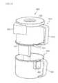
- FIG. 1is a front, perspective view of a vacuum cleaner according to an embodiment
- FIG. 2is a front, perspective view of a vacuum cleaner from which a dust collector is separated;
- FIG. 3is a rear, perspective view of a dust collector of the vacuum cleaner of FIG. 1-2 .
- FIG. 4is a cross-sectional view taken along I-I′ of FIG. 3 ;
- FIG. 5is a lower perspective view of the dust collector of the vacuum cleaner of FIGS. 1-2 ;
- FIG. 6is a perspective view of a driven gear of the vacuum cleaner of FIGS. 1-2 ;
- FIG. 7is a perspective view of a dust collector mounting element of the vacuum cleaner of FIGS. 1-2 ;
- FIG. 8is a block diagram showing a control structure of the vacuum cleaner of FIGS. 1-2 ;
- FIGS. 9 and 10are views showing a position relationship between a magnetic element and a second magnetic sensor when a first pressing element is placed adjacent to one side of a second pressing element;
- FIGS. 11 and 12are views showing a position relationship between the magnetic element and the second magnetic sensor when the first and second pressing elements are oriented substantially in a straight line;
- FIGS. 13 and 14are views showing a position relationship between the magnetic element and the second magnetic sensor when the first pressing element is placed adjacent to the other side of the second pressing element;
- FIG. 15is a view illustrating a rotational operation of the first pressing element of FIGS. 9 to 14 ;
- FIG. 16is a flow chart of a control method of the vacuum cleaner of FIGS. 1-2 ;
- FIG. 17is a lower perspective view of a driven gear according to another embodiment.
- FIG. 18is a perspective view of a dust collector mounting element according to another embodiment
- FIG. 19is a view showing a position relationship between the driven gear of FIG. 17 and the installation sensor of FIG. 18 ;
- FIG. 20is a front, perspective view of an upright vacuum according to an embodiment.
- a vacuum cleaneris an appliance that sucks air containing particles using a suction force of a suction motor into a body thereof and filters off the particles in the body.
- the vacuum cleanermay include an intake nozzle that sucks air containing particles or impurities, a cleaner body that communicates with the intake nozzle, an extension pipe that guides the air sucked in by the intake nozzle into the cleaner body, and a connecting pipe that connects the extension pipe with the cleaner body.
- An intake portmay be formed at a lower surface of the intake nozzle so that air containing particles may be sucked off of a floor to be cleaned.
- a suction motor that generates a sucking force to suck in air containing particlesmay be provided in the cleaner body.
- a dust collector that stores impurities separated from polluted airmay be detachably provided in the cleaner body.
- the dust collectormay include a dust separator that separates impurities from the air sucked into the dust collector, and a dust container that stores the impurities separated by the dust separator. If an operation of the vacuum cleaner is stopped while separating impurities from polluted air, the separated impurities are stored in the dust container at low density.
- FIG. 1is a front, perspective view of a vacuum cleaner according to an embodiment.
- FIG. 2is a front, perspective view of a vacuum cleaner from which a dust collector is separated.
- FIG. 3is a rear, perspective view of a dust collector of the vacuum cleaner of FIGS. 1-2 .
- a vacuum cleaner 10may include a cleaner body 100 , in which a suction motor (not shown) that generates a sucking force may be provided, and a dust separating device that separates dust from air sucked into the cleaner body 100 .
- the vacuum cleanermay also include an intake nozzle that sucks air containing dust off of a floor and a connection device that connects the intake nozzle to the cleaner body 100 , though not illustrated.
- the basic configurations of the intake nozzle and the connection deviceare known, and therefore detailed description has been omitted.
- a body intake port 110through which air containing dust sucked in by the intake nozzle passes, may be formed at a bottom of a front surface of the cleaner body 100 , and a body discharge port (not shown) that discharges air separated from dust to the outside may be formed in one side of the cleaner body 100 .
- a body handle 140which is grabable by a user, may be formed on an upper part of the cleaner body 100 .
- the dust separating devicemay include a dust collector 200 , in which a primary cyclone device 230 , which will be explained later, that separates dust from air introduced therein is provided, and a secondary cyclone device 300 , which is provided in the cleaner body 100 , that re-separates dust from the air initially separated by the primary cyclone device 230 .
- the dust collector 200may be detachably mounted on a dust collector mounting element 170 formed in a front of the cleaner body 100 .
- An attachment/detachment lever 142may be provided in the handle 140 of the cleaner body 100 , and an engagement end 256 that engages with the attachment/detachment lever 142 may be formed in the dust collector 200 .
- the dust collector 200may include the primary cyclone device 230 that forms a cyclonic flow, and a dust collector body 210 , in which a dust container that stores the dust separated by the primary cyclone device 230 may be formed.
- the dust collector 200may communicate with the cleaner body 100 and the secondary cyclone device 300 , as the dust collector 200 may be attached to the cleaner body 100 .
- an air outlet 130that discharges air sucked into the cleaner body to the dust collector 200 may be formed.
- a first air inlet 218 that introduces air from the air outlet 130may also be provided in the dust collector 200 .
- a first air outlet 252through which air separated from the dust by the primary cyclone device 230 may be discharged, may be formed in the dust collector 200 , and a connecting channel 114 , into which the air discharged through the first air outlet 252 may be introduced, may be formed in the cleaner body 100 .
- the air introduced into the connecting channel 114may be introduced into the secondary cyclone device 300 .
- the secondary cyclone device 300may include a plurality of cyclones.
- the dust separated by the secondary cyclone device 300may be stored in the dust collector 200 .
- a dust inlet 254into which the dust separated by the secondary cyclone device 300 may be introduced, may be formed in the dust collector body 210 .
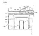
- FIG. 4is a cross-sectional view taken along I-I′ of FIG. 3 .
- FIG. 5is a lower perspective view of the dust collector of the vacuum cleaner of FIGS. 1-2 .
- FIG. 6is a perspective view of a driven gear of the vacuum cleaner of FIGS. 1-2 .
- FIG. 7is a perspective view of a dust collector mounting element of the vacuum cleaner of FIGS. 1-2 .
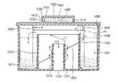
- the dust collector 200may include the dust collector body 210 that defines an external appearance, the primary cyclone device 230 provided in the dust collector body 210 to separate dust from air, and a cover element 250 that selectively opens or closes an upper part of the dust collector body 210 .
- a dust container in which the separated dust may be storedis formed in the dust collector body 210 .
- the dust containermay include a first dust container 214 , in which the dust separated by the primary cyclone device 230 may be stored, and a second dust container 216 , in which the dust separated by the secondary cyclone device 300 may be stored.
- the dust collector body 210may include a first wall 211 that defines the first dust container 214 , and a second wall 212 that defines the second dust container 216 in relation to the first wall 211 . That is, the second wall 212 may be formed to surround an external portion of the first wall 211 . Therefore, the second dust container 216 may be formed outside of the first dust container 214 .
- a dust guide channel 232that guides the dust separated from air into the first dust container 214 may be provided.
- An inlet 233 of the dust guide channel 232may be formed at a side of the primary cyclone device 230 , and an outlet 234 may be formed at a bottom of the primary cyclone device 230 .
- the cover element 250may be detachably connected to a top of the dust collecting body 210 , as described above.
- the cover element 250may open or close the first and second containers 214 , 216 at the same time.
- the primary cyclone device 230may be connected to a lower part of the cover element 250 .
- a discharge hole 251through which the air separated from the dust in the primary cyclone device 230 may be passed, may be formed in a lower surface of the cover element 250 .
- a filter element 260in which a plurality of perforated-holes 262 of a specific size may be formed in a circumferential surface thereof, may be connected to a lower surface of the cover element 250 .
- a channel 253 that guides the air of the primary cyclone device 230 discharged from the discharge hole 251 to the first air outlet 252may be formed in the cover element 250 .
- the channel 253may serve as a passage connecting the discharge hole 251 with the first air outlet 252 .
- a pair of pressing elements 270 , 280 that increase a dust-collecting capacity by reducing a volume of dust stored in the first dust container 214may be provided in the dust collector body 210 .
- the pair of pressing elements 270 , 280may reduce the volume of dust by compressing the dust by reciprocal action of the pressing elements. Therefore, the dust-collecting capacity of the dust collector 200 may be increased by increasing the density of the dust stored in the dust collector body 210 .
- one of the pair of pressing elements 270 , 280may be referred to as a first pressing element 270
- the othermay be referred to as a second pressing element 280 .
- At least one of the pair of pressing elements 270 , 280may be movably provided in the dust collector 200 , so that the dust may be compressed between the pair of pressing elements 270 , 280 . That is, if the first and second pressing elements 270 , 280 are rotatably provided in the dust collector 200 , a distance between one side of the first pressing element 270 and one side of second pressing element 280 , which is opposite to the one side of the first pressing element 270 , may be decreased as the first and second pressing elements 270 , 280 are rotated to each other. Therefore, the dust disposed between the pair of pressing elements 270 , 280 may be compressed.
- the first pressing element 270may be rotatably provided in the dust collector body 210 and the second pressing element 280 may be fixedly provided in the dust collector body 210 . Therefore, the first pressing element 270 may be a rotating element, and the second pressing element 280 may be a fixed element.
- the second pressing element 280may be disposed between an inner circumferential surface of the dust collector body 210 and an axial line of a rotational axis 272 , which is a center of rotation of the first pressing element 270 . That is, the second pressing element 280 may be provided on a surface connecting the axial line of the rotational axis 272 with the inner circumferential surface of the first dust container 214 . The second pressing element 280 may fully or partially close a space between the inner circumferential surface of the first dust container 214 and the axial line of the rotational axis 272 . Therefore, the second pressing element 280 and the first pressing element 270 may compress dust when the dust is moved by the first pressing element 270 .
- One end of the second pressing element 280may be integrally formed with an inner circumferential surface of the dust collector body 210 , and the other end may be integrally formed with a fixed axis 282 , which may be the same axis as the rotational axis 272 of the first pressing element 270 . Further, only one end of the second pressing element 280 may be integrally formed with the inner circumferential surface of the dust collector body 210 , or only the other end may be integrally formed with the fixed axis 282 . In other words, the second pressing element 280 may be fixed on at least one of the inner circumferential surface of the dust collecting body 210 or the fixed axis 282 .
- the one end of the second pressing element 280may be placed adjacent to the inner circumferential surface of the dust collector body 210 .
- the other endmay be placed adjacent to the fixed axis 282 . This prevents the dust introduced by the first pressing element 270 from leaking through a gap between the second pressing element 280 and the inner circumferential surface of the dust collector body 210 .
- the first and second pressing elements 270 , 280may include a plate having a rectangular shape.
- the rotational axis 272 of the first pressing element 270may be positioned along the same axis as an axial line constituting a center of the dust collector body 210 .
- the fixed axis 282may protrude upwardly from a lower surface of the dust collector body 210 , and a hollow hole 283 that passes in an axial direction for connection of the rotational axis 272 may be formed in the fixed axis 282 . A portion of the rotational axis 272 may be inserted into the hollow hole 283 from the upper part of the fixed axis 282 .
- a step 272 cwhich is supported by a top of the fixed axis 282 , may be formed on the rotational axis 272 .
- the rotational axis 272may be divided into an upper axis 272 a , to which the first pressing element 270 may be connected, and a lower axis 272 b , to which a driven gear that rotates the first pressing element 270 may be connected, with reference to the step 272 c.
- the vacuum cleaner according to this embodimentmay further include a driving device selectively connected to the first pressing element 270 to rotate the first pressing element 270 .
- the driving device that rotates the first pressing element 270may include a compression motor 570 that generates a driving force, and a power transmission device that transmits the driving force of the compression motor 570 to the first pressing element 270 .
- the power transmission devicemay include a driven gear 410 connected to the rotational axis 272 of the first pressing element 270 , and a driving gear 420 that transmits power from the compression motor 570 to the driven gear 410 .
- the driving gear 420may be rotated by the compression motor 570 , as it may be connected to the rotational axis of the compression motor 570 .
- the compression motor 570is rotated, the driving gear 420 connected with the compression motor 570 is rotated, and thus, the driven gear 410 is rotated because the rotational force of the compression motor 570 is transmitted to the driven gear 410 by the driving gear 420 .
- the first pressing element 270may be rotated by the rotation of the driven gear 410 .
- An axis 414 of the driven gear 410may be connected with the rotational axis 272 of the first pressing element 270 at a lower part of the dust collector body 210 . As described above, the driven gear 410 may be exposed to the outside of the dust collector body 210 .
- the compression motor 570may be provided below the dust collector mounting element 170 , and the driving gear 420 may be provided at a bottom of the dust collector mounting element 170 , as it may be connected to a rotational axis of the compression motor 570 . Further, some of an outer circumferential surface of the driving gear 420 may be exposed at the bottom of the dust collector mounting element 170 . An opening 173 that exposes some of the driving gear 420 may be formed in the dust collector mounting element 170 . As the driven gear 410 is exposed in the dust collector mounting element 170 , if the dust collector 200 is mounted on the dust collector mounting element 170 , then the driven gear 410 may engage with the driving gear 420 .
- the compression motor 570may rotate in forward and reverse directions.
- a motor capable of rotating bi-directionallymay be used as the compression motor.
- the first pressing element 270may rotate in forward and reverse directions, and the compressed dust may be accumulated on both sides of the second pressing element 280 as the first pressing element 270 rotates in the forward and reverse directions.
- a synchronous motormay be used as the compression motor.
- the synchronous motormay be configured such that the forward/reverse rotation may be enabled by the motor itself. That is, if the force exerted on the motor is greater than a set value when the motor rotates in one direction, then the motor rotates in the other direction.
- the force exerted on the motormay be a resisting force (torque), which may be created as the first pressing element 270 presses the dust.
- the rotational direction of the motormay be changed when the resisting force reaches the set value. Synchronous motors are generally known in the art, and thus, detailed explanation has been omitted.
- the first pressing element 270may continuously press the dust for a predetermined period of time, even when the first pressing element 270 reaches a stationary point where no more rotation is possible, as it compresses the dust due to the rotation.
- the stationary point, where the first pressing element 270 cannot rotate any more,may correspond to the case in which the resisting force reaches the set value.
- the power rotating the first pressing elementthat is, the power source applied to the compression motor
- the first pressing element 270may keep pressing the dust
- the first pressing element 270may be able to move by applying the power to the compression motor 570 after the predetermined period of time elapses. Since the cut off time of the power applied to the compression motor may be the time that the resisting force reaches the set value, if the compression motor 570 is driven again, then the rotational direction of the compression motor 570 is opposite to the rotational direction of the compression motor 570 before the power was cut off. In order to easily compress the dust, the compression motor 570 may continually rotate the first pressing element 270 in the forward and reverse directions at the same angular velocity.
- a guide rib 290 that guides installation of the dust collector 200may be formed in the lower part of the dust collector body 210 , and an insert groove 172 , in which the guide rib 290 may be inserted, may be formed in the dust collector mounting element 170 .
- the guide rib 290may be provided at an outside of the driven gear 410 in the shape of “C” Therefore, the guide rib 290 may protect the driven gear 410 and prevent dust from getting onto the driven gear 410 .
- the driven gear 410may include a body 412 , and a plurality of gear teeth 416 formed along a side surface of the body 412 .
- a magnetic element 415may be provided in the body 412 . More particularly, the magnetic element 415 may extend from a center of the body 412 to an edge of the body 412 in a radial direction.
- a plurality of magnetic sensors that detect magnetism of the magnetic element 415may be provided on an inner side of the dust collector mounting element 170 .
- the magnetic sensorsmay include a first magnetic sensor 440 that detects installation of the dust collector 200 , and a second magnetic sensor 450 that detects a state of rotation of the driven gear 410 .
- the first magnetic sensor 440may be provided at a center of the insert groove 172 to detect magnetism of an A portion of the magnetic element 415 .
- the second magnetic sensor 450may be placed apart from the first magnetic sensor 440 and may detect magnetism of a B portion of the magnetic element 415 .
- the dust collector 200may be mounted on the dust collector mounting element 170 and may be disposed vertically below a trajectory of the magnetic element 415 when the driven gear 410 is rotated, so that the second magnetic sensor 450 may effectively detect magnetism generated from the magnetic element 415 . Therefore, the first magnetic sensor 440 may always detects magnetism when the dust collector 200 is mounted on the dust collector mounting element 170 .
- the second magnetic sensor 450may detect magnetism only when the magnetic element 415 is disposed vertically above the second magnetic sensor 450 while the driven gear 410 is rotated. Therefore, it may be possible to check a rotational state of the driven gear 410 .
- One magnetic elementmay be provided in the driven gear according to this embodiment; however, it is also possible that a first magnetic element may be provided at the center of the driven gear and a second magnetic element may be provided at a position spaced apart from the first magnetic element.
- the first magnetic sensor 440may detect magnetism of the first magnetic element
- the second magnetic sensor 450may detect magnetism of the second magnetic element.
- FIG. 8is a block diagram of a control structure of the vacuum cleaner of FIGS. 1-2 .
- the vacuum cleanermay include a controller 510 , an operation signal input device 520 that selects the suction power (for example, high, medium and low modes) for dust, a signal display 530 that displays an empty signal regarding dust stored in the dust collector 200 and a dust collector uninstallation signal, a suction motor driver 540 that operates a suction motor according to the operation mode input from the operation signal input device 520 , and a compression motor driver 560 that operates a compression motor 570 , which is used to compress dust stored in the dust collector 200 .
- the suction powerfor example, high, medium and low modes
- a signal display 530that displays an empty signal regarding dust stored in the dust collector 200 and a dust collector uninstallation signal
- a suction motor driver 540that operates a suction motor according to the operation mode input from the operation signal input device 520
- a compression motor driver 560that operates a compression motor 570 , which is
- the vacuum cleanermay further include a driving gear 420 driven by the compression motor 570 , a driven gear 410 rotated by engagement with the driving gear 420 , a magnetic element 415 provided in the driven gear 410 , a first magnetic sensor 440 , and a second magnetic sensor 450 .
- the dust collector 200is not mounted on the dust collector mounting element 170 , then magnetism of the magnetic element 415 may not be detected by the first magnetic sensor 440 . Therefore, if the operation signal is input from the operation signal input device 520 while the dust collector 200 is not mounted on the dust collector mounting element 170 , then the dust collector uninstallation signal may be displayed.
- the controller 510may determine an amount of dust stored in the dust collector 200 with reference to the rotational state of the driven gear 410 , which is detected by the second magnetic sensor 450 . If the controller 510 determines that the amount of dust is greater than a specific value, then the dust empty signal may be displayed at or on the signal display 530 . Since the driven gear 410 and the first pressing element 270 may be connected, the rotational state of the driven gear 410 may be found by checking the rotation position of the first pressing element 270 .
- the first magnetic sensor 440may be referred to as a “dust collector sensor”, because it detects the mounting of the dust collector 200
- the second magnetic sensor 450may be referred to as a “position sensor,” because it detects the position of the first pressing element 270 .
- the signal displayed at or on the signal display 530may be a sound signal, a visual signal, or a vibration directly transmitted to users.
- a speaker, a LED, or a vibration motor, for example,may be used as the signal display 530 .
- the signal displayed at or on the signal display 530may be differently set for the dust empty signal and the dust collector uninstallation signal.
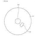
- FIGS. 9 and 10show a position relationship between a magnetic element and a second magnetic sensor when a first pressing element is placed adjacent to one side of a second pressing element.
- FIGS. 11 and 12show a position relationship between the magnetic element and the second magnetic sensor when the first and second pressing elements are oriented substantially in a straight line.
- FIGS. 13 and 14show a position relationship between the magnetic element and the second magnetic sensor when the first pressing element is placed adjacent to the other side of the second pressing element.
- the magnetic element 415may be positioned vertically above the second magnetic sensor 450 , and thus, the second magnetic sensor 450 may detect magnetism of the magnetic element 415 .
- the position of the first pressing element 270 , where the second magnetic sensor 450 detects magnetism of the magnetic element 415may be referred to as a “reference position.”
- the magnetic element 415may be spaced apart from the second magnetic sensor 450 , and therefore, magnetism may not be detected by the second magnetic sensor 450 . Additionally, if the first pressing element 270 , which rotates in a counter-clockwise direction, is not further rotated, then the first pressing element 270 may start to rotate in a clockwise direction. Therefore, the first pressing element 270 may press dust accumulated in the dust collector 200 , as it rotates to the right of the second pressing element 280 , as in FIG. 13 , by passing through the reference point in FIG. 11 .
- the first pressing element 270which rotates in a clockwise direction, is not further rotated, then the first pressing element 270 may start to rotate in a counter-clockwise direction. Therefore, the first pressing element 270 may press dust accumulated in the dust collector 200 by repeating the above-mentioned process.
- FIG. 15illustrates a rotational operation of the first pressing element of FIGS. 9 to 14 .
- a time TD 1 required for the first pressing element 270 to return to the reference position from the reference position by rotating in a clockwise directionand a time TD 2 required for the first pressing element 270 to return to the reference position from the reference position by rotating in a counter-clockwise direction may be displayed.
- the time TD 1may be referred to as a “first turnaround”
- the time TD 2may be referred to as a “second turnaround.”
- the time TD 1 and the time TD 2may be almost the same.
- the time TD 1 and the time TD 2get shorter. According to this embodiment, when one of the time TD 1 and the time TD 2 reaches a specific reference time, it may be determined that dust is sufficiently accumulated in the dust collector 200 , and therefore, the dust empty signal may be displayed.
- FIG. 16is a flow chart of a control method of the vacuum cleaner according to an embodiment. Referring to FIG. 16 , it may be determined whether the suction motor operation signal is input through the operation signal input device 520 in a state in which the vacuum cleaner is deactivated, in step S 10 . When the suction motor operation signal is input, it may be determined whether the dust collector 200 is mounted or not, in step S 11 .
- the signal indicating the dust collector is not mountedmay be displayed at or on the signal display 530 , in step S 12 .
- unnecessary operation of the suction motor and the compression motormay be prevented by informing a user of this state via the signal display 530 .
- the controller 510may activate the suction motor driver 540 , so that the suction motor 550 is activated according to the suction power selected by a user, in step S 13 . If the suction motor 550 is activated, then dust may be introduced through the suction nozzle by the suction force of the suction motor 550 . The air sucked in through the suction nozzle may be introduced into the cleaner body 100 via the body intake port 110 , and the introduced air may be introduced into the dust collector 200 via a predetermined channel.
- the air introduced into the dust collector 200may be discharged to the cleaner body 100 after being filtered.
- the separated dustmay be stored in the first dust container 214 .
- the pair of pressing element 270 , 280may press the dust stored in the first dust container 214 . That is, the controller 510 may activate the compression motor 570 in order to compress the dust stored in the dust collector 200 , in step S 14 .
- the compression motor 570may be driven after activating the suction motor 550 .
- the compression motor 570If the compression motor 570 is activated, the driving gear 420 connected with the rotational axis of the compression motor 570 may be rotated. If the driving gear 420 is rotated, the driven gear 410 may be rotated. If the driven gear 410 is rotated, the dust may be compressed as the first pressing element 270 connected with the driven gear 410 may be rotated to the second pressing element 280 .
- the controller 510may initially determine whether the first pressing element 270 is positioned at the reference position, in step S 15 . According to this embodiment, since the first and second turnarounds may be measured with reference to the reference position, it is necessary to determine whether the first pressing element 270 is positioned at the reference position for the first movement.
- the reference position of the first pressing element 270may be checked when magnetism of the magnetic element 415 is initially detected by the second magnetic sensor 450 in the case of the first movement of the compression motor 570 . Therefore, the controller 510 may measure the turnarounds of the first pressing element 270 with reference to a time when the second magnetic sensor 450 initially detects magnetism.
- first and second turnarounds TD 1 , TD 2may be measured from the time when the first pressing element 270 moves to the reference position by rotating the first pressing element 270 in a clockwise or counter-clockwise direction, in step S 16 .
- the rotation turnaround time period of the driven gear 410may be reduced.
- the controller 510may determine the first and second turnarounds TD 1 and TD 2 of the first pressing element 270 by using the second magnetic sensor 450 , and therefore, it may determine that the first and second turnarounds TD 1 and TD 2 reach the specific reference time, in step S 17 .
- the specific reference timemay be set in the controller 510 by a designer. The reference time may be obtained by experiment, and may have different values according to a particular capacity of the vacuum cleaner.
- the amount of dustmay be determined to reach the specific amount.
- the amount of dustmay be determined to reach the specific amount only when both of the time TD 1 and the time TD 2 reach the reference tune.
- step S 17if any one of the time TD 1 and the time TD 2 is longer than the reference time, then the process may return to step S 16 and accomplish the previous process. However, if the time TD 1 or the time TD 2 reaches the reference time, the dust empty signal of the dust collector 200 may be displayed at or on the signal display 530 , in step S 18 .
- the controller 510may turn off the suction motor 550 to prevent dust from being introduced therein, in step S 19 . That is, the suction motor 550 may be forcibly stopped, since the suction efficiency may be reduced and the suction motor 550 overloaded when the suction operation is continuously performed while the amount of dust accumulated in the dust collector 200 exceeds the specific amount. Further, the controller 510 may turn off the compression motor 570 , in step S 20 .
- unnecessary operation of the suction motor and the compression motormay be prevented by displaying the uninstallation signal of the dust collector 200 , and convenience of a user may be increased because the dust empty time is known to the user.
- FIG. 17is a lower perspective view of a driven gear according to an embodiment.
- FIG. 18is a perspective view of a dust collector mounting element according to the embodiment of FIG. 17 .
- FIG. 19shows a position relationship between the driven gear of FIG. 17 and the installation sensor of FIG. 18 .
- This embodimentis the same as the previous embodiment, except for a difference in the structure of detecting the installation of the dust collector. Therefore, repetitive description has been omitted.
- installation of the dust collectormay be detected by a microswitch 640 provided in the dust collector mounting element 170 , and a rotational position of a driven gear 610 may be detected by a magnetic sensor 630 provided in the dust collector mounting element 170 .
- the microswitch 640may be a dust collector sensor that detects the installation of the dust collector
- the magnetic sensor 630may be a position sensor that detects the position of the driven gear 610 .
- the driven gear 610may include a body 612 , and a plurality of gear teeth 614 formed along a side surface of the body 612 .
- a pressing element 616may be formed in a bottom of the body 612 .
- the pressing element 616may be formed along a bottom edge of the body 612 and may downwardly protrude from the body 612 .
- a magnetic element 620may be provided in the body 612 .
- the microswitch 640may be provided in the cleaner body 100 .
- a terminal 650 connected with the microswitch 640may be exposed to the outside of the dust collector mounting element 170 .
- the pressing element 616may press the terminal 650 when the dust collector is mounted on the dust collector mounting element 170 . If the terminal 650 is pressed, the terminal 650 may push a contact 642 of the microswitch. As described above, if the contact is pressed by the terminal 650 , the installation of the dust collector may be detected.
- microswitchA more detailed explanation of the microswitch is provided in U.S. patent application Ser. No. 11/956,133, which is hereby incorporated by reference.
- the magnetic sensor 620 that detects magnetism of the magnetic element 620may be provided in the dust collector mounting element 170 .
- the terminal 650 and the magnetic sensor 620may be disposed vertically below a trajectory of the pressing element when the driven gear 410 is rotated.
- the magnetic detection of the magnetic sensor 620may be the same as that of the second magnetic sensor according to the previous embodiment. Therefore, detailed description has been omitted.
- any of the embodiments disclosed hereinmay be employed in an upright vacuum cleaner, such as the vacuum cleaner 1000 shown in FIG. 20 .
- the dust separator 1210may be contained within the dust collector body 1220 or the dust separator 1210 may be separately provided from the dust collector body 1220 . More detailed explanations of uptight vacuum cleaners are provided in U.S. Pat. Nos. 6,922,868 and 7,462,210, which are hereby incorporated by reference.
- the installation of the dust collectormay be detected by the magnetic sensor or the microswitch.
- the installation of the dust collectormay also be detected by using an infrared sensor or a sonar sensor of the dust collector mounting element.
- a dust-collecting capacity of the dust collectormay be maximized, since dust stored in the dust collector may be pressed by the pressing element.
- Embodiments disclosed hereinhave been derived to resolve disadvantages of the prior art.
- Embodiments disclosed hereinprovide a vacuum cleaner that increases dust-collecting capacity by compressing dust stored in the dust collector. Further, embodiments disclosed herein provide a vacuum cleaner that prevents a suction motor or a compression motor that compresses dust from operating when a dust collector is not mounted thereon.
- Embodiments disclosed hereinprovide a vacuum cleaner that may include a cleaner body, in which a suction motor is provided; a dust collector selectively attached to the cleaner body, in which a dust container is formed; a pressing element that presses dust stored in the dust container; a compression motor that operates the pressing element; an installation sensor provided in a mounting element of the dust collector to detect whether the dust collector is correctly mounted; a signal display that displays a mount status of the dust collector; and a control unit or controller that controls the operation of the signal display.
- a vacuum cleanermay include a cleaner body, in which a dust collector mounting element is formed; a dust collector detachably attached to the dust collector mounting element, in which a dust container is formed; a pressing element movably provided in the dust container to press dust stored in the dust container; a magnetic element that moves with the pressing element when the pressing element moves; a magnetic sensor that detects a magnetism of the magnetic element; and a control unit or controller that determines a storage amount of dust stored in the dust container by using the magnetic information of the magnetic sensor.
- a vacuum cleanermay include a cleaner body, in which a dust collector mounting element is formed; a dust collector detachably attached to the dust collector mounting element, in which a dust container is formed; a pressing element provided in the dust container to press dust stored in the dust container; an installation sensor provided in the dust collector mounting element that detects whether the dust collector is correctly mounted; and a position sensor provided in the dust collector mounting element that detects a position of the pressing element.
- the capacity of dust stored in the dust collectormay be maximized. Also, a user's inconvenience in having to frequently empty the dust stored in the dust collector may be solved or reduced, as the dust-collecting capacity of the dust collector may be maximized by a dust compressing operation.
- a dust empty signalmay be displayed, and therefore, it is possible for a user to easily recognize a time to empty the dust container. Furthermore, when an operation signal of the suction motor is input in a state in which the dust collector is not mounted thereon, unnecessary operations of the suction motor and the compression motor may be prevented by informing the user.
- any reference in this specification to “one embodiment,” “an embodiment,” “example embodiment,” etc.means that a particular feature, structure, or characteristic described in connection with the embodiment is included in at least one embodiment of the invention.
- the appearances of such phrases in various places in the specificationare not necessarily all referring to the same embodiment.
Landscapes
- Engineering & Computer Science (AREA)
- Mechanical Engineering (AREA)
- Electric Vacuum Cleaner (AREA)
- Filters For Electric Vacuum Cleaners (AREA)
Abstract
Description
Claims (21)
Priority Applications (1)
| Application Number | Priority Date | Filing Date | Title |
|---|---|---|---|
| US12/407,964US8012250B2 (en) | 2005-12-10 | 2009-03-20 | Vacuum cleaner |
Applications Claiming Priority (38)
| Application Number | Priority Date | Filing Date | Title |
|---|---|---|---|
| KR1020050121279AKR101248722B1 (en) | 2005-12-10 | 2005-12-10 | Dust Collector and Vacuum Cleaner Having the Same |
| KR2005-0121279 | 2005-12-20 | ||
| KR2005-0126270 | 2005-12-20 | ||
| KR1020050126270AKR101250038B1 (en) | 2005-12-20 | 2005-12-20 | Vacuum Cleaner |
| KR2005-0134094 | 2005-12-29 | ||
| KR1020050134094AKR101250103B1 (en) | 2005-12-29 | 2005-12-29 | vacuum cleaner |
| KR2006-0018119 | 2006-02-24 | ||
| KR1020060018120AKR100871485B1 (en) | 2006-02-24 | 2006-02-24 | Operation Method of Dust Compaction Dust Collector |
| KR2006-0018120 | 2006-02-24 | ||
| KR1020060018119AKR100871483B1 (en) | 2006-02-24 | 2006-02-24 | Dust collector and vacuum cleaner having same |
| KR2006-0040106 | 2006-05-03 | ||
| KR1020060040106AKR101282457B1 (en) | 2006-05-03 | 2006-05-03 | Dust seperation apparatus and vaccum cleaner equipped it |
| KR2006-0044362 | 2006-05-17 | ||
| KR2006-0044359 | 2006-05-17 | ||
| KR1020060044359AKR100846904B1 (en) | 2006-05-17 | 2006-05-17 | Vacuum cleaner |
| KR1020060044362AKR100846900B1 (en) | 2006-05-17 | 2006-05-17 | Vacuum cleaner |
| KR1020060045416AKR100906848B1 (en) | 2006-05-20 | 2006-05-20 | Vacuum cleaner |
| KR1020060045415AKR100895145B1 (en) | 2006-05-20 | 2006-05-20 | How to control the vacuum cleaner |
| KR2006-0045416 | 2006-05-20 | ||
| KR2006-0045415 | 2006-05-20 | ||
| KR1020060046077AKR100871487B1 (en) | 2006-05-23 | 2006-05-23 | How to control the vacuum cleaner |
| KR2006-0046077 | 2006-05-23 | ||
| KR1020060085921AKR100876694B1 (en) | 2006-09-06 | 2006-09-06 | How to control the vacuum cleaner |
| KR2006-0085921 | 2006-09-06 | ||
| KR2006-0085919 | 2006-09-06 | ||
| KR1020060085919AKR100906849B1 (en) | 2006-09-06 | 2006-09-06 | Vacuum cleaner and its control method |
| KR1020060098191AKR100833362B1 (en) | 2006-10-10 | 2006-10-10 | How to control the vacuum cleaner |
| KR2006-0098191 | 2006-10-10 | ||
| US11/565,206US7882592B2 (en) | 2005-12-10 | 2006-11-30 | Vacuum cleaner |
| US11/565,241US7749295B2 (en) | 2005-12-10 | 2006-11-30 | Vacuum cleaner with removable dust collector, and methods of operating the same |
| KR2007-0015806 | 2007-02-15 | ||
| KR1020070015806AKR100800189B1 (en) | 2007-02-15 | 2007-02-15 | Vacuum cleaner |
| KR2007-0073222 | 2007-07-23 | ||
| KR1020070073222AKR100947361B1 (en) | 2007-07-23 | 2007-07-23 | Vacuum cleaner |
| PCT/KR2007/005758WO2008100005A1 (en) | 2007-02-15 | 2007-11-15 | Vacuum cleaner |
| KRPCT/KR2007/005758 | 2007-11-15 | ||
| WOPCT/KR2007/005758 | 2007-11-15 | ||
| US12/407,964US8012250B2 (en) | 2005-12-10 | 2009-03-20 | Vacuum cleaner |
Related Parent Applications (1)
| Application Number | Title | Priority Date | Filing Date |
|---|---|---|---|
| US11/565,241Continuation-In-PartUS7749295B2 (en) | 2005-12-10 | 2006-11-30 | Vacuum cleaner with removable dust collector, and methods of operating the same |
Publications (2)
| Publication Number | Publication Date |
|---|---|
| US20090241286A1 US20090241286A1 (en) | 2009-10-01 |
| US8012250B2true US8012250B2 (en) | 2011-09-06 |
Family
ID=41119571
Family Applications (1)
| Application Number | Title | Priority Date | Filing Date |
|---|---|---|---|
| US12/407,964Expired - Fee RelatedUS8012250B2 (en) | 2005-12-10 | 2009-03-20 | Vacuum cleaner |
Country Status (1)
| Country | Link |
|---|---|
| US (1) | US8012250B2 (en) |
Cited By (14)
| Publication number | Priority date | Publication date | Assignee | Title |
|---|---|---|---|---|
| US20090229072A1 (en)* | 2005-12-10 | 2009-09-17 | Lg Electronics Inc. | Vacuum cleaner with removable dust collector, and methods of operating the same |
| US20090293221A1 (en)* | 2005-12-10 | 2009-12-03 | Lg Electronics Inc. | Vacuum cleaner with removable dust collector, and methods of operating the same |
| US20100319307A1 (en)* | 2009-06-17 | 2010-12-23 | Samsung Gwangju Electronics Co., Ltd. | Dust collecting apparatus of vacuum cleaner having function of removing dust detached from filter |
| US20160088989A1 (en)* | 2014-09-29 | 2016-03-31 | Lg Electronics Inc. | Dust collector for vacuum cleaner |
| US20160113463A1 (en)* | 2014-10-28 | 2016-04-28 | Lg Electronics Inc. | Vacuum cleaner |
| US20160150929A1 (en)* | 2014-12-01 | 2016-06-02 | Lg Electronics Inc. | Vacuum cleaner and dust collecting apparatus |
| US20180255995A1 (en)* | 2015-01-16 | 2018-09-13 | Lg Electronics Inc. | Dust collecting apparatus |
| USD840615S1 (en) | 2016-10-14 | 2019-02-12 | Tti (Macao Commercial Offshore) Limited | Handheld vacuum cleaner |
| USD844265S1 (en) | 2016-10-14 | 2019-03-26 | Tti (Macao Commercial Offshore) Limited | Handheld vacuum cleaner |
| US10470625B2 (en) | 2016-04-15 | 2019-11-12 | Tti (Macao Commercial Offshore) Limited | Vacuum cleaner and filter for a vacuum cleaner |
| USD911642S1 (en) | 2017-12-05 | 2021-02-23 | Techtronic Floor Care Technology Limited | Housing for a filter |
| US11058273B2 (en) | 2017-09-28 | 2021-07-13 | Techtronic Floor Care Technology Limited | Vacuum cleaner |
| US11607637B2 (en) | 2018-08-31 | 2023-03-21 | Milwaukee Electric Tool Corporation | Power tool including an air filter and debris collector |
| US11834008B2 (en) | 2020-02-06 | 2023-12-05 | Pony Al Inc. | Rotating glass sensor cleaning system and methods of operation |
Families Citing this family (33)
| Publication number | Priority date | Publication date | Assignee | Title |
|---|---|---|---|---|
| US8978197B2 (en)* | 2009-03-13 | 2015-03-17 | Lg Electronics Inc. | Vacuum cleaner |
| US8281455B2 (en)* | 2005-12-10 | 2012-10-09 | Lg Electronics Inc. | Vacuum cleaner |
| US8404034B2 (en) | 2005-12-10 | 2013-03-26 | Lg Electronics Inc. | Vacuum cleaner and method of controlling the same |
| US7882592B2 (en)* | 2005-12-10 | 2011-02-08 | Lg Electronics Inc. | Vacuum cleaner |
| US7987551B2 (en)* | 2005-12-10 | 2011-08-02 | Lg Electronics Inc. | Vacuum cleaner |
| US8012250B2 (en) | 2005-12-10 | 2011-09-06 | Lg Electronics Inc. | Vacuum cleaner |
| EP1949842B1 (en)* | 2007-01-24 | 2015-03-04 | LG Electronics Inc. | Vacuum cleaner |
| KR100996531B1 (en)* | 2008-07-02 | 2010-11-24 | 엘지전자 주식회사 | Vacuum cleaner |
| US8528163B2 (en)* | 2009-02-12 | 2013-09-10 | Lg Electronics Inc. | Vacuum cleaner |
| US8151409B2 (en)* | 2009-02-26 | 2012-04-10 | Lg Electronics Inc. | Vacuum cleaner |
| US8713752B2 (en)* | 2009-03-13 | 2014-05-06 | Lg Electronics Inc. | Vacuum cleaner |
| KR101340207B1 (en)* | 2009-08-24 | 2013-12-10 | 엘지전자 주식회사 | Vacuum cleaner |
| US8474092B2 (en)* | 2009-11-01 | 2013-07-02 | Lg Electronics Inc. | Vacuum cleaner |
| US8370992B2 (en)* | 2009-11-01 | 2013-02-12 | Lg Electronics Inc. | Vacuum cleaner |
| US20120011679A1 (en)* | 2009-11-03 | 2012-01-19 | Lg Electronics Inc. | Vacuum cleaner |
| AU2009354996B2 (en)* | 2009-11-03 | 2012-12-20 | Lg Electronics Inc. | Vacuum cleaner |
| USD683093S1 (en)* | 2010-08-19 | 2013-05-21 | Samsung Electronics Co., Ltd. | Vacuum cleaner |
| US8978198B2 (en) | 2011-03-03 | 2015-03-17 | G.B.D. Corp. | Filter housing for a surface cleaning apparatus |
| US8813306B2 (en) | 2011-03-03 | 2014-08-26 | G.B.D. Corp. | Openable side compartments for a surface cleaning apparatus |
| US8869345B2 (en)* | 2011-03-03 | 2014-10-28 | G.B.D. Corp. | Canister vacuum cleaner |
| US8973212B2 (en) | 2011-03-03 | 2015-03-10 | G.B.D. Corp. | Filter housing construction for a surface cleaning apparatus |
| US8973214B2 (en) | 2011-03-03 | 2015-03-10 | G.B.D. Corp. | Cyclone chamber and dirt collection assembly for a surface cleaning apparatus |
| US8763202B2 (en) | 2011-03-03 | 2014-07-01 | G.B.D. Corp. | Cyclone chamber and dirt collection assembly for a surface cleaning apparatus |
| US8739357B2 (en) | 2011-03-03 | 2014-06-03 | G.B.D. Corp | Filter construction for a surface cleaning apparatus |
| US9101252B2 (en) | 2011-03-03 | 2015-08-11 | G.B.D. Corp. | Configuration of a surface cleaning apparatus |
| US8739359B2 (en) | 2011-03-03 | 2014-06-03 | G.B.D. Corp. | Configuration of a surface cleaning apparatus |
| US8769767B2 (en) | 2011-03-03 | 2014-07-08 | G.B.D. Corp. | Removable cyclone chamber and dirt collection assembly for a surface cleaning apparatus |
| GB2503253B (en) | 2012-06-20 | 2014-10-15 | Dyson Technology Ltd | A cleaning appliance |
| GB2503255B (en)* | 2012-06-20 | 2014-10-15 | Dyson Technology Ltd | A cleaning appliance |
| GB2503254B (en) | 2012-06-20 | 2014-12-17 | Dyson Technology Ltd | A cleaning appliance |
| GB2503252B (en) | 2012-06-20 | 2014-12-17 | Dyson Technology Ltd | A self righting cleaning appliance |
| GB2503251C (en)* | 2012-06-20 | 2015-07-15 | Dyson Technology Ltd | A self righting cleaning appliance |
| EP3323334B1 (en)* | 2016-11-17 | 2019-06-05 | Black & Decker Inc. | Vacuum cleaner |
Citations (119)
| Publication number | Priority date | Publication date | Assignee | Title |
|---|---|---|---|---|
| US83469A (en) | 1868-10-27 | Peters | ||
| US2283836A (en) | 1940-12-07 | 1942-05-19 | Hoover Co | Suction cleaner |
| US2714426A (en) | 1953-01-21 | 1955-08-02 | Hoover Co | Suction cleaner having a cleaning and disposable dirt storing container |
| US3367462A (en) | 1964-01-22 | 1968-02-06 | William H. Bibbens | Torque transmitter with yieldable teeth |
| US4379385A (en) | 1980-10-06 | 1983-04-12 | Ulf Reinhall | Compaction apparatus for use with lawn grooming equipment |
| US4545794A (en) | 1981-11-13 | 1985-10-08 | Sanyo Electric Co., Ltd. | Vacuum cleaner |
| US4601082A (en) | 1984-02-08 | 1986-07-22 | Gerhard Kurz | Vacuum cleaner |
| US4617034A (en) | 1982-03-30 | 1986-10-14 | Sharp Kabushiki Kaisha | Electric cleaner with minimum noise |
| SU1326236A1 (en) | 1986-02-03 | 1987-07-30 | Ю. Ф. Киселев, В. М. Опанасюк и А. В. Кр чек | Vacuum cleaner |
| US4809394A (en) | 1986-08-29 | 1989-03-07 | Hitachi, Ltd. | Vacuum cleaner having a blower facility structure |
| US5033151A (en) | 1988-12-16 | 1991-07-23 | Interlava Ag | Control and/or indication device for the operation of vacuum cleaners |
| US5135552A (en) | 1990-12-05 | 1992-08-04 | U.S. Philips Corp. | Vacuum cleaner |
| US5159738A (en) | 1988-06-06 | 1992-11-03 | Hitachi, Ltd. | Vacuum cleaner having silencer mechanism |
| US5233682A (en) | 1990-04-10 | 1993-08-03 | Matsushita Electric Industrial Co., Ltd. | Vacuum cleaner with fuzzy control |
| US5251358A (en) | 1990-11-26 | 1993-10-12 | Matsushita Electric Industrial Co., Ltd. | Vacuum cleaner with fuzzy logic |
| US5265305A (en) | 1989-01-21 | 1993-11-30 | Interlava Ag | Automatic control device for the cleaning power of a vacuum cleaner |
| CN2162679Y (en) | 1992-11-09 | 1994-04-20 | 沈阳新乐精密机器公司 | Automatic sound alarm device for dust full of dust collector |
| US5323483A (en) | 1991-06-25 | 1994-06-21 | Goldstar Co., Ltd. | Apparatus and method for controlling speed of suction motor in vacuum cleaner |
| CN2186039Y (en) | 1993-12-07 | 1994-12-28 | 苏州春花吸尘器总厂 | Fuzzy controlled dust collector |
| US5542146A (en) | 1994-05-12 | 1996-08-06 | Electrolux Corporation | Electronic vacuum cleaner control system |
| JP2000262449A (en) | 1999-03-15 | 2000-09-26 | Matsushita Electric Ind Co Ltd | Electric vacuum cleaner |
| CN2409894Y (en) | 1999-11-17 | 2000-12-13 | 谢明毅 | Isolating impedance-changing speed regulator for suction cleaner |
| JP3119575B2 (en) | 1995-10-04 | 2000-12-25 | 株式会社東海理化電機製作所 | Resin mold key |
| US6192550B1 (en) | 1999-01-29 | 2001-02-27 | Sanyo Electric Co., Ltd. | Dust-collecting device for vacuum cleaner and upright type vacuum cleaner |
| RU2172132C1 (en) | 2000-01-22 | 2001-08-20 | Самсунг Электроникс Ко., Лтд. | Vacuum cleaner |
| US20010025395A1 (en) | 2000-03-24 | 2001-10-04 | Yukimichi Matsumoto | Electric vacuum cleaner |
| CN1334061A (en) | 2000-07-26 | 2002-02-06 | 三星光州电子株式会社 | Cyclone dust-collector of vacuum cleaner |
| JP2002143060A (en) | 2000-11-13 | 2002-05-21 | Sharp Corp | Electric vacuum cleaner |
| US20020073505A1 (en) | 2000-07-20 | 2002-06-20 | Bolden Kurt E. | Device and method for liquid removal from carpet |
| JP2002187336A (en) | 2000-12-21 | 2002-07-02 | Tohoku Ricoh Co Ltd | Waste plate housing device and stencil printing machine |
| US20020088079A1 (en) | 2001-01-11 | 2002-07-11 | Samsung Kwangju Electronics Co., Ltd. | Upright type vacuum cleaner |
| US20020124538A1 (en) | 2001-03-12 | 2002-09-12 | Jang-Keun Oh | Cyclone dust collecting apparatus for vacuum cleaner |
| US6460217B2 (en) | 2000-01-20 | 2002-10-08 | Sanyo Electric Co., Ltd. | Electric cleaning device |
| KR20020091510A (en) | 2001-05-31 | 2002-12-06 | 삼성광주전자 주식회사 | Cyclone-type dust collecting apparatus for a vacuum cleaner |
| JP2002360474A (en) | 2001-06-05 | 2002-12-17 | Toshiba Tec Corp | Dust collector and vacuum cleaner |
| GB2368516B (en) | 2000-11-06 | 2003-01-15 | Samsung Kwangju Electronics Co | Cyclone dust collecting apparatus for a vacuum cleaner |
| JP2003019097A (en) | 2001-07-06 | 2003-01-21 | Toshiba Tec Corp | Dust collection container and vacuum cleaner |
| JP2003119575A (en) | 2001-10-11 | 2003-04-23 | National Institute Of Advanced Industrial & Technology | Composite structure forming method and composite structure forming apparatus |
| JP2003125995A (en) | 2001-10-29 | 2003-05-07 | Matsushita Electric Ind Co Ltd | Electric vacuum cleaner |
| FR2823091B1 (en) | 2001-04-09 | 2003-06-13 | Seb Sa | DEVICE FOR COMPACTING WASTE IN A VACUUM |
| GB2377881B (en) | 2001-07-25 | 2003-06-25 | Samsung Kwangju Electronics Co | Cyclone dust collecting apparatus and upright-type vacuum cleaner |
| JP2003190056A (en) | 2001-12-28 | 2003-07-08 | Matsushita Electric Ind Co Ltd | Electric vacuum cleaner |
| JP2003199695A (en) | 2002-01-07 | 2003-07-15 | Mitsubishi Electric Corp | Electric vacuum cleaner |
| CN1434749A (en) | 2000-02-17 | 2003-08-06 | Lg电子株式会社 | Cyclone dust collector |
| DE10240618A1 (en) | 2002-03-05 | 2003-09-25 | Samsung Kwangju Electronics Co | Vacuum cleaner with reusable filter |
| JP2003310506A (en) | 2002-04-22 | 2003-11-05 | Mitsubishi Electric Corp | Cyclone vacuum cleaner |
| JP2003310502A (en) | 2002-04-23 | 2003-11-05 | Hitachi Home & Life Solutions Inc | Electric vacuum cleaner |
| EP1371318A2 (en) | 2002-06-11 | 2003-12-17 | Hitachi Home & Life Solutions, Inc., | Electric vacuum cleaner |
| US6689225B2 (en) | 1999-05-21 | 2004-02-10 | Vortex Holding Company | Toroidal vortex vacuum cleaner with alternative collection apparatus |
| US6694917B1 (en) | 2003-05-28 | 2004-02-24 | Meiko Pet Corporation | Feeding apparatus |
| JP2004065357A (en) | 2002-08-02 | 2004-03-04 | Matsushita Electric Ind Co Ltd | Electric vacuum cleaner |
| GB2388769B (en) | 2002-05-22 | 2004-04-28 | Samsung Kwangju Electronics Co | vacuum cleaner apparatus with both disposable and reusable filters |
| US6735816B2 (en) | 2001-06-04 | 2004-05-18 | Samsung Gwangju Electronics Co., Ltd. | Upright-type vacuum cleaner |
| US6779229B2 (en) | 2000-09-22 | 2004-08-24 | Daewoo Electronics Corporation | Versatile vacuum cleaner |
| US6782584B2 (en) | 2002-02-06 | 2004-08-31 | Samsung Gwangju Electronics Co., Ltd. | Upright type vacuum cleaner |
| JP2004528087A (en) | 2001-04-12 | 2004-09-16 | ダイソン・リミテッド | Cyclone separator |
| JP2004528876A (en) | 2001-02-24 | 2004-09-24 | ダイソン・リミテッド | Suction cleaner collection room |
| US20040211025A1 (en) | 2003-04-28 | 2004-10-28 | Samsung Gwangju Electronics Co., Ltd. | Cyclone-type dust collecting apparatus for vacuum cleaner |
| US20040261216A1 (en) | 2003-06-26 | 2004-12-30 | Choi Min-Jo | Locking unit of cyclone type dust collecting apparatus |
| RU2243714C1 (en) | 2002-11-29 | 2005-01-10 | Самсунг Гвангджу Электроникс Ко., Лтд | Dust-trap cyclone type apparatus for vacuum cleaner |
| GB2404887A (en) | 2003-08-13 | 2005-02-16 | Dyson Ltd | Grooved outlet for cyclonic separating apparatus |
| CN1593324A (en) | 2003-09-09 | 2005-03-16 | 三星光州电子株式会社 | Cyclone separating apparatus and vacuum cleaner having the same |
| US20050091787A1 (en) | 1998-01-09 | 2005-05-05 | Royal Appliance Mfg. Co. | Upright vacuum cleaner with cyclonic airflow |
| US20050138763A1 (en) | 2003-08-05 | 2005-06-30 | Mark Tanner | Cyclonic vacuum cleaner |
| US6922868B1 (en) | 1999-11-15 | 2005-08-02 | Lg Electronics Inc. | Union device for dust-box in cyclone type vacuum cleaner |
| US20050172584A1 (en) | 2004-02-11 | 2005-08-11 | Samsung Gwangju Electronics Co., Ltd | Cyclone dust-collector |
| WO2005099545A1 (en) | 2004-04-07 | 2005-10-27 | Toshiba Tec Kabushiki Kaisha | Dust collection vessel and vacuum cleaner |
| CN1695538A (en) | 2004-05-14 | 2005-11-16 | 三星光州电子株式会社 | Cyclone tube dust collector and vacuum cleaner including the cyclone tube dust collector |
| CN1695537A (en) | 2004-05-14 | 2005-11-16 | 三星光州电子株式会社 | Multi-cyclone container dust collection unit for vacuum cleaners |
| KR100546629B1 (en) | 2005-01-04 | 2006-01-26 | 엘지전자 주식회사 | Dust collector of vacuum cleaner |
| KR100553042B1 (en) | 2004-12-27 | 2006-02-15 | 엘지전자 주식회사 | Dust collection unit of vacuum cleaner |
| RU2269919C2 (en) | 2004-04-02 | 2006-02-20 | Борис Аркадьевич Криман | Liquid vacuum cleaner with one or more suction branch pipes |
| JP2006068500A (en) | 2004-09-04 | 2006-03-16 | Samsung Electronics Co Ltd | Vacuum cleaner |
| US7028369B2 (en) | 2002-09-24 | 2006-04-18 | Samsung Gwangju Electronics Co., Ltd. | Combination wet and dry type vacuum cleaner |
| CN1778246A (en) | 2004-11-24 | 2006-05-31 | 乐金电子(天津)电器有限公司 | Dust amount detector and method for automatic dust collector |
| US20060123750A1 (en) | 2004-12-14 | 2006-06-15 | Lg Electronics Inc. | Dust compressing apparatus and method for dust collecting unit of vacuum cleaner |
| AU2005229774A1 (en) | 2005-02-15 | 2006-08-31 | Vax Limited | Twin cyclone dust box |
| US20060230722A1 (en) | 2005-03-29 | 2006-10-19 | Samsung Gwangju Electronics Co., Ltd. | Multi-cyclone apparatus for vacuum cleaner |
| GB2406064B (en) | 2003-09-08 | 2006-11-08 | Samsung Kwangju Electronics Co | Cyclonic separating apparatus |
| KR20060116992A (en) | 2005-05-12 | 2006-11-16 | 엘지전자 주식회사 | Vacuum cleaner |
| JP2006340972A (en) | 2005-06-10 | 2006-12-21 | Toshiba Tec Corp | Electric vacuum cleaner |
| US7152276B2 (en) | 2003-04-14 | 2006-12-26 | Samsung Gwangju Electronics Co., Ltd. | Filter assembly for a cyclone-type dust collecting apparatus of vacuum cleaner |
| JP2007007381A (en) | 2005-05-31 | 2007-01-18 | Toshiba Tec Corp | Electric vacuum cleaner |
| US20070136980A1 (en) | 2005-12-16 | 2007-06-21 | Matsushita Electric Industrial Co., Ltd. | Vacuum cleaner |
| KR100730956B1 (en) | 2006-04-27 | 2007-06-22 | 주식회사 대우일렉트로닉스 | Dust Collector Compressor of Vacuum Cleaner |
| US20070143953A1 (en) | 2005-12-10 | 2007-06-28 | Hwang Man T | Vacuum cleaner |
| GB2416721B (en) | 2004-07-29 | 2007-07-11 | Dyson Ltd | Separating apparatus |
| US20070209339A1 (en) | 2006-03-10 | 2007-09-13 | Gbd Corp. | Vacuum cleaner with a plurality of cyclonic cleaning stages |
| US20070209149A1 (en) | 2006-03-07 | 2007-09-13 | Samsung Gwangju Electronics Co., Ltd. | Vacuum cleaner |
| EP1857032A2 (en) | 2006-05-17 | 2007-11-21 | LG Electronics Inc. | Vacuum cleaner having primary and secondary cyclone units |
| US20080023035A1 (en) | 2005-12-10 | 2008-01-31 | Ha Gun Ho | Vacuum cleaner with removable dust collector, and methods of operating the same |
| US20080023036A1 (en) | 2005-12-10 | 2008-01-31 | Ha Gun H | Vacuum cleaner with removable dust collector, and methods of operating the same |
| KR100800188B1 (en) | 2007-02-15 | 2008-02-01 | 엘지전자 주식회사 | Vacuum cleaner and his dust collector |
| KR100800189B1 (en) | 2007-02-15 | 2008-02-01 | 엘지전자 주식회사 | Vacuum cleaner |
| US7351269B2 (en) | 2003-12-22 | 2008-04-01 | Lau Kwok Yau | Self cleaning filter and vacuum incorporating same |
| KR100838886B1 (en) | 2007-01-24 | 2008-06-16 | 엘지전자 주식회사 | Vacuum cleaner |
| KR100838887B1 (en) | 2007-01-24 | 2008-06-16 | 엘지전자 주식회사 | Vacuum cleaner |
| US20080172993A1 (en) | 2007-01-24 | 2008-07-24 | Yun Chang Ho | Dust collector of vacuum cleaner |
| US20080172824A1 (en) | 2007-01-24 | 2008-07-24 | Yun Chang Ho | Vacuum cleaner |
| AU2007200406B2 (en) | 2006-02-24 | 2008-08-21 | Lg Electronics Inc | Dust collector and vacuum cleaner |
| US20080264007A1 (en) | 2007-04-30 | 2008-10-30 | Samsung Gwangju Electronics Co., Ltd. | Dust collecting apparatus for vacuum cleaner |
| US20080263816A1 (en) | 2007-04-30 | 2008-10-30 | Samsung Gwangju Electronics Co., Ltd. | Vacuum cleaner |
| US20080264016A1 (en) | 2007-04-30 | 2008-10-30 | Samsung Gwangju Electronics Co., Ltd. | Vacuum Cleaner |
| US20080264015A1 (en) | 2007-04-30 | 2008-10-30 | Samsung Gwangju Electronics Co., Ltd | Dust compressing apparatus of vacuum cleaner |
| US20080264014A1 (en) | 2007-04-30 | 2008-10-30 | Samsung Gwangju Electronics Co. Ltd. | Dust compressing apparatus of vacuum cleaner |
| US7475449B2 (en) | 2003-12-24 | 2009-01-13 | Daewoo Electronics Corporation | Vacuum cleaner |
| US7547340B2 (en) | 2004-12-14 | 2009-06-16 | Lg Electronics Inc. | Dust collecting unit of vacuum cleaner |
| US20090241286A1 (en) | 2005-12-10 | 2009-10-01 | Man Tae Hwang | Vacuum cleaner |
| US20090249578A1 (en) | 2005-12-10 | 2009-10-08 | Man Tae Hwang | Vacuum cleaner |
| US20090255083A1 (en) | 2005-12-10 | 2009-10-15 | Man Tae Hwang | Vacuum cleaner |
| US7608123B2 (en) | 2003-01-24 | 2009-10-27 | Massimiliano Pineschi | Vacuum cleaner |
| US20090266382A1 (en) | 2005-12-10 | 2009-10-29 | Man Tae Hwang | Vacuum cleaner and method of controlling the same |
| US20090293221A1 (en) | 2005-12-10 | 2009-12-03 | Lg Electronics Inc. | Vacuum cleaner with removable dust collector, and methods of operating the same |
| US20090293224A1 (en) | 2007-03-16 | 2009-12-03 | Hyun Kie-Tak | Vacuum cleaner and dust separating apparatus thereof |
| US7644469B2 (en) | 2007-10-11 | 2010-01-12 | Black & Decker Inc. | Vacuum electronics isolation method |
| US7647672B2 (en) | 2004-07-16 | 2010-01-19 | Lg Electronics Inc. | Vacuum cleaner |
| US7704290B2 (en) | 2006-03-24 | 2010-04-27 | Samsung Gwangju Electronics Co., Ltd. | Cyclone dust collecting apparatus for vacuum cleaner |
| GB2466625A (en) | 2008-12-23 | 2010-06-30 | Vax Ltd | Dust receptacle with dust compression means |
| US7785396B2 (en) | 2005-12-10 | 2010-08-31 | Lg Electronics Inc. | Vacuum cleaner with removable dust collector, and methods of operating the same |
- 2009
- 2009-03-20USUS12/407,964patent/US8012250B2/ennot_activeExpired - Fee Related
Patent Citations (148)
| Publication number | Priority date | Publication date | Assignee | Title |
|---|---|---|---|---|
| US83469A (en) | 1868-10-27 | Peters | ||
| US2283836A (en) | 1940-12-07 | 1942-05-19 | Hoover Co | Suction cleaner |
| US2714426A (en) | 1953-01-21 | 1955-08-02 | Hoover Co | Suction cleaner having a cleaning and disposable dirt storing container |
| US3367462A (en) | 1964-01-22 | 1968-02-06 | William H. Bibbens | Torque transmitter with yieldable teeth |
| US4379385A (en) | 1980-10-06 | 1983-04-12 | Ulf Reinhall | Compaction apparatus for use with lawn grooming equipment |
| US4545794A (en) | 1981-11-13 | 1985-10-08 | Sanyo Electric Co., Ltd. | Vacuum cleaner |
| US4617034A (en) | 1982-03-30 | 1986-10-14 | Sharp Kabushiki Kaisha | Electric cleaner with minimum noise |
| US4601082A (en) | 1984-02-08 | 1986-07-22 | Gerhard Kurz | Vacuum cleaner |
| US4601082C1 (en) | 1984-02-08 | 2001-04-24 | Interlava Ag | Vacuum cleaner |
| SU1326236A1 (en) | 1986-02-03 | 1987-07-30 | Ю. Ф. Киселев, В. М. Опанасюк и А. В. Кр чек | Vacuum cleaner |
| US4809394A (en) | 1986-08-29 | 1989-03-07 | Hitachi, Ltd. | Vacuum cleaner having a blower facility structure |
| US5159738A (en) | 1988-06-06 | 1992-11-03 | Hitachi, Ltd. | Vacuum cleaner having silencer mechanism |
| US5033151A (en) | 1988-12-16 | 1991-07-23 | Interlava Ag | Control and/or indication device for the operation of vacuum cleaners |
| US5265305A (en) | 1989-01-21 | 1993-11-30 | Interlava Ag | Automatic control device for the cleaning power of a vacuum cleaner |
| US5233682A (en) | 1990-04-10 | 1993-08-03 | Matsushita Electric Industrial Co., Ltd. | Vacuum cleaner with fuzzy control |
| US5251358A (en) | 1990-11-26 | 1993-10-12 | Matsushita Electric Industrial Co., Ltd. | Vacuum cleaner with fuzzy logic |
| US5135552A (en) | 1990-12-05 | 1992-08-04 | U.S. Philips Corp. | Vacuum cleaner |
| US5323483A (en) | 1991-06-25 | 1994-06-21 | Goldstar Co., Ltd. | Apparatus and method for controlling speed of suction motor in vacuum cleaner |
| CN2162679Y (en) | 1992-11-09 | 1994-04-20 | 沈阳新乐精密机器公司 | Automatic sound alarm device for dust full of dust collector |
| CN2186039Y (en) | 1993-12-07 | 1994-12-28 | 苏州春花吸尘器总厂 | Fuzzy controlled dust collector |
| US5542146A (en) | 1994-05-12 | 1996-08-06 | Electrolux Corporation | Electronic vacuum cleaner control system |
| JP3119575B2 (en) | 1995-10-04 | 2000-12-25 | 株式会社東海理化電機製作所 | Resin mold key |
| US20050091787A1 (en) | 1998-01-09 | 2005-05-05 | Royal Appliance Mfg. Co. | Upright vacuum cleaner with cyclonic airflow |
| US6192550B1 (en) | 1999-01-29 | 2001-02-27 | Sanyo Electric Co., Ltd. | Dust-collecting device for vacuum cleaner and upright type vacuum cleaner |
| JP2000262449A (en) | 1999-03-15 | 2000-09-26 | Matsushita Electric Ind Co Ltd | Electric vacuum cleaner |
| US6689225B2 (en) | 1999-05-21 | 2004-02-10 | Vortex Holding Company | Toroidal vortex vacuum cleaner with alternative collection apparatus |
| US6922868B1 (en) | 1999-11-15 | 2005-08-02 | Lg Electronics Inc. | Union device for dust-box in cyclone type vacuum cleaner |
| CN2409894Y (en) | 1999-11-17 | 2000-12-13 | 谢明毅 | Isolating impedance-changing speed regulator for suction cleaner |
| US6460217B2 (en) | 2000-01-20 | 2002-10-08 | Sanyo Electric Co., Ltd. | Electric cleaning device |
| RU2172132C1 (en) | 2000-01-22 | 2001-08-20 | Самсунг Электроникс Ко., Лтд. | Vacuum cleaner |
| CN1434749A (en) | 2000-02-17 | 2003-08-06 | Lg电子株式会社 | Cyclone dust collector |
| JP2003524522A (en) | 2000-02-17 | 2003-08-19 | エルジー エレクトロニクス インコーポレーテッド | Cyclone dust collector |
| US20010025395A1 (en) | 2000-03-24 | 2001-10-04 | Yukimichi Matsumoto | Electric vacuum cleaner |
| US6625845B2 (en) | 2000-03-24 | 2003-09-30 | Sharp Kabushiki Kaisha | Cyclonic vacuum cleaner |
| US20020073505A1 (en) | 2000-07-20 | 2002-06-20 | Bolden Kurt E. | Device and method for liquid removal from carpet |
| CN1334061A (en) | 2000-07-26 | 2002-02-06 | 三星光州电子株式会社 | Cyclone dust-collector of vacuum cleaner |
| US6779229B2 (en) | 2000-09-22 | 2004-08-24 | Daewoo Electronics Corporation | Versatile vacuum cleaner |
| GB2368516B (en) | 2000-11-06 | 2003-01-15 | Samsung Kwangju Electronics Co | Cyclone dust collecting apparatus for a vacuum cleaner |
| JP2002143060A (en) | 2000-11-13 | 2002-05-21 | Sharp Corp | Electric vacuum cleaner |
| JP2002187336A (en) | 2000-12-21 | 2002-07-02 | Tohoku Ricoh Co Ltd | Waste plate housing device and stencil printing machine |
| US20020088079A1 (en) | 2001-01-11 | 2002-07-11 | Samsung Kwangju Electronics Co., Ltd. | Upright type vacuum cleaner |
| JP2004528876A (en) | 2001-02-24 | 2004-09-24 | ダイソン・リミテッド | Suction cleaner collection room |
| US20020124538A1 (en) | 2001-03-12 | 2002-09-12 | Jang-Keun Oh | Cyclone dust collecting apparatus for vacuum cleaner |
| FR2823091B1 (en) | 2001-04-09 | 2003-06-13 | Seb Sa | DEVICE FOR COMPACTING WASTE IN A VACUUM |
| JP2004528087A (en) | 2001-04-12 | 2004-09-16 | ダイソン・リミテッド | Cyclone separator |
| KR20020091510A (en) | 2001-05-31 | 2002-12-06 | 삼성광주전자 주식회사 | Cyclone-type dust collecting apparatus for a vacuum cleaner |
| US6735816B2 (en) | 2001-06-04 | 2004-05-18 | Samsung Gwangju Electronics Co., Ltd. | Upright-type vacuum cleaner |
| JP2002360474A (en) | 2001-06-05 | 2002-12-17 | Toshiba Tec Corp | Dust collector and vacuum cleaner |
| JP2003019097A (en) | 2001-07-06 | 2003-01-21 | Toshiba Tec Corp | Dust collection container and vacuum cleaner |
| GB2377881B (en) | 2001-07-25 | 2003-06-25 | Samsung Kwangju Electronics Co | Cyclone dust collecting apparatus and upright-type vacuum cleaner |
| US6757933B2 (en) | 2001-07-25 | 2004-07-06 | Samsung Gwangju Electronics Co., Ltd. | Cyclone dust collecting apparatus and upright vacuum cleaner |
| JP2003119575A (en) | 2001-10-11 | 2003-04-23 | National Institute Of Advanced Industrial & Technology | Composite structure forming method and composite structure forming apparatus |
| JP2003125995A (en) | 2001-10-29 | 2003-05-07 | Matsushita Electric Ind Co Ltd | Electric vacuum cleaner |
| JP2003190056A (en) | 2001-12-28 | 2003-07-08 | Matsushita Electric Ind Co Ltd | Electric vacuum cleaner |
| JP2003199695A (en) | 2002-01-07 | 2003-07-15 | Mitsubishi Electric Corp | Electric vacuum cleaner |
| US6782584B2 (en) | 2002-02-06 | 2004-08-31 | Samsung Gwangju Electronics Co., Ltd. | Upright type vacuum cleaner |
| DE10240618A1 (en) | 2002-03-05 | 2003-09-25 | Samsung Kwangju Electronics Co | Vacuum cleaner with reusable filter |
| JP2003310506A (en) | 2002-04-22 | 2003-11-05 | Mitsubishi Electric Corp | Cyclone vacuum cleaner |
| JP2003310502A (en) | 2002-04-23 | 2003-11-05 | Hitachi Home & Life Solutions Inc | Electric vacuum cleaner |
| GB2388769B (en) | 2002-05-22 | 2004-04-28 | Samsung Kwangju Electronics Co | vacuum cleaner apparatus with both disposable and reusable filters |
| EP1371318A2 (en) | 2002-06-11 | 2003-12-17 | Hitachi Home & Life Solutions, Inc., | Electric vacuum cleaner |
| JP2004065357A (en) | 2002-08-02 | 2004-03-04 | Matsushita Electric Ind Co Ltd | Electric vacuum cleaner |
| US7028369B2 (en) | 2002-09-24 | 2006-04-18 | Samsung Gwangju Electronics Co., Ltd. | Combination wet and dry type vacuum cleaner |
| RU2243714C1 (en) | 2002-11-29 | 2005-01-10 | Самсунг Гвангджу Электроникс Ко., Лтд | Dust-trap cyclone type apparatus for vacuum cleaner |
| US7608123B2 (en) | 2003-01-24 | 2009-10-27 | Massimiliano Pineschi | Vacuum cleaner |
| US7152276B2 (en) | 2003-04-14 | 2006-12-26 | Samsung Gwangju Electronics Co., Ltd. | Filter assembly for a cyclone-type dust collecting apparatus of vacuum cleaner |
| US20040211025A1 (en) | 2003-04-28 | 2004-10-28 | Samsung Gwangju Electronics Co., Ltd. | Cyclone-type dust collecting apparatus for vacuum cleaner |
| US6694917B1 (en) | 2003-05-28 | 2004-02-24 | Meiko Pet Corporation | Feeding apparatus |
| US20040261216A1 (en) | 2003-06-26 | 2004-12-30 | Choi Min-Jo | Locking unit of cyclone type dust collecting apparatus |
| US20050138763A1 (en) | 2003-08-05 | 2005-06-30 | Mark Tanner | Cyclonic vacuum cleaner |
| GB2404887A (en) | 2003-08-13 | 2005-02-16 | Dyson Ltd | Grooved outlet for cyclonic separating apparatus |
| GB2406064B (en) | 2003-09-08 | 2006-11-08 | Samsung Kwangju Electronics Co | Cyclonic separating apparatus |
| CN1593324A (en) | 2003-09-09 | 2005-03-16 | 三星光州电子株式会社 | Cyclone separating apparatus and vacuum cleaner having the same |
| US7351269B2 (en) | 2003-12-22 | 2008-04-01 | Lau Kwok Yau | Self cleaning filter and vacuum incorporating same |
| US7475449B2 (en) | 2003-12-24 | 2009-01-13 | Daewoo Electronics Corporation | Vacuum cleaner |
| US20050172584A1 (en) | 2004-02-11 | 2005-08-11 | Samsung Gwangju Electronics Co., Ltd | Cyclone dust-collector |
| RU2269919C2 (en) | 2004-04-02 | 2006-02-20 | Борис Аркадьевич Криман | Liquid vacuum cleaner with one or more suction branch pipes |
| WO2005099545A1 (en) | 2004-04-07 | 2005-10-27 | Toshiba Tec Kabushiki Kaisha | Dust collection vessel and vacuum cleaner |
| CN1777385A (en) | 2004-04-07 | 2006-05-24 | 东芝泰格株式会社 | Dust collectors and electric vacuum cleaners |
| EP1733669B1 (en) | 2004-04-07 | 2010-10-13 | Toshiba TEC Kabushiki Kaisha | Dust collection vessel and vacuum cleaner comprising such dust collector |
| JP2005324002A (en) | 2004-05-14 | 2005-11-24 | Samsung Kwangju Electronics Co Ltd | Multiple cyclone dust collector |
| CN1695538A (en) | 2004-05-14 | 2005-11-16 | 三星光州电子株式会社 | Cyclone tube dust collector and vacuum cleaner including the cyclone tube dust collector |
| US20050252179A1 (en) | 2004-05-14 | 2005-11-17 | Jang-Keun Oh | Multi cyclone vessel dust collecting apparatus for vacuum cleaner |
| CN1695537A (en) | 2004-05-14 | 2005-11-16 | 三星光州电子株式会社 | Multi-cyclone container dust collection unit for vacuum cleaners |
| US7647672B2 (en) | 2004-07-16 | 2010-01-19 | Lg Electronics Inc. | Vacuum cleaner |
| GB2416721B (en) | 2004-07-29 | 2007-07-11 | Dyson Ltd | Separating apparatus |
| JP2006068500A (en) | 2004-09-04 | 2006-03-16 | Samsung Electronics Co Ltd | Vacuum cleaner |
| CN1778246A (en) | 2004-11-24 | 2006-05-31 | 乐金电子(天津)电器有限公司 | Dust amount detector and method for automatic dust collector |
| EP1671569B1 (en) | 2004-12-14 | 2009-09-16 | LG Electronics Inc. | Dust collecting unit of vacuum cleaner and vacuum cleaner with the dust collecting unit |
| EP1671570B1 (en) | 2004-12-14 | 2010-10-20 | LG Electronics, Inc. | Dust collecting unit of vacuum cleaner and dust compressing method for dust collecting unit |
| US20080052870A1 (en) | 2004-12-14 | 2008-03-06 | Lee Jae H | Vacuum Cleaner |
| US7547340B2 (en) | 2004-12-14 | 2009-06-16 | Lg Electronics Inc. | Dust collecting unit of vacuum cleaner |
| US7481868B2 (en)* | 2004-12-14 | 2009-01-27 | Lg Electronics Inc. | Dust compressing apparatus and method for dust collecting unit of vacuum cleaner |
| US20060123750A1 (en) | 2004-12-14 | 2006-06-15 | Lg Electronics Inc. | Dust compressing apparatus and method for dust collecting unit of vacuum cleaner |
| KR100553042B1 (en) | 2004-12-27 | 2006-02-15 | 엘지전자 주식회사 | Dust collection unit of vacuum cleaner |
| KR100546629B1 (en) | 2005-01-04 | 2006-01-26 | 엘지전자 주식회사 | Dust collector of vacuum cleaner |
| AU2005229774A1 (en) | 2005-02-15 | 2006-08-31 | Vax Limited | Twin cyclone dust box |
| US20060230722A1 (en) | 2005-03-29 | 2006-10-19 | Samsung Gwangju Electronics Co., Ltd. | Multi-cyclone apparatus for vacuum cleaner |
| KR20060116992A (en) | 2005-05-12 | 2006-11-16 | 엘지전자 주식회사 | Vacuum cleaner |
| JP2007007381A (en) | 2005-05-31 | 2007-01-18 | Toshiba Tec Corp | Electric vacuum cleaner |
| JP2006340972A (en) | 2005-06-10 | 2006-12-21 | Toshiba Tec Corp | Electric vacuum cleaner |
| US20090255083A1 (en) | 2005-12-10 | 2009-10-15 | Man Tae Hwang | Vacuum cleaner |
| US7785396B2 (en) | 2005-12-10 | 2010-08-31 | Lg Electronics Inc. | Vacuum cleaner with removable dust collector, and methods of operating the same |
| US20070143953A1 (en) | 2005-12-10 | 2007-06-28 | Hwang Man T | Vacuum cleaner |
| US7749295B2 (en) | 2005-12-10 | 2010-07-06 | Lg Electronics Inc. | Vacuum cleaner with removable dust collector, and methods of operating the same |
| US7770253B2 (en) | 2005-12-10 | 2010-08-10 | Lg Electronics Inc. | Vacuum cleaner with removable dust collector, and methods of operating the same |
| US20090293221A1 (en) | 2005-12-10 | 2009-12-03 | Lg Electronics Inc. | Vacuum cleaner with removable dust collector, and methods of operating the same |
| US20090293915A1 (en) | 2005-12-10 | 2009-12-03 | Lg Electronics Inc. | Vacuum cleaner with removable dust collector, and methods of operatng the same |
| US20090229072A1 (en) | 2005-12-10 | 2009-09-17 | Lg Electronics Inc. | Vacuum cleaner with removable dust collector, and methods of operating the same |
| US20090293223A1 (en) | 2005-12-10 | 2009-12-03 | Lg Electronics Inc | Vacuum cleaner with removable dust collector, and methods of operating the same |
| US20090229073A1 (en) | 2005-12-10 | 2009-09-17 | Lg Electronics Inc. | Vaccum cleaner with removable dust collector, and methods of operating the same |
| US20090266382A1 (en) | 2005-12-10 | 2009-10-29 | Man Tae Hwang | Vacuum cleaner and method of controlling the same |
| US20090235956A1 (en) | 2005-12-10 | 2009-09-24 | Lg Electronics Inc. | Vacuum cleaner with removable dust collector, and methods of operating the same |
| US20080047094A1 (en) | 2005-12-10 | 2008-02-28 | Ha Gun H | Vacuum cleaner with removable dust collector, and methods of opertating the same |
| US20090241286A1 (en) | 2005-12-10 | 2009-10-01 | Man Tae Hwang | Vacuum cleaner |
| US20080023036A1 (en) | 2005-12-10 | 2008-01-31 | Ha Gun H | Vacuum cleaner with removable dust collector, and methods of operating the same |
| US20080023035A1 (en) | 2005-12-10 | 2008-01-31 | Ha Gun Ho | Vacuum cleaner with removable dust collector, and methods of operating the same |
| US7601188B2 (en) | 2005-12-10 | 2009-10-13 | Lg Electronics Inc. | Vacuum cleaner |
| US20090178231A1 (en) | 2005-12-10 | 2009-07-16 | Lg Electronics, Inc. | Vaccum cleaner with removable dust collector, and methods of operating the same |
| US20090249578A1 (en) | 2005-12-10 | 2009-10-08 | Man Tae Hwang | Vacuum cleaner |
| US7582128B2 (en) | 2005-12-10 | 2009-09-01 | Lg Electronics Inc. | Vacuum cleaner |
| US20070136980A1 (en) | 2005-12-16 | 2007-06-21 | Matsushita Electric Industrial Co., Ltd. | Vacuum cleaner |
| AU2007200406B2 (en) | 2006-02-24 | 2008-08-21 | Lg Electronics Inc | Dust collector and vacuum cleaner |
| US20070209149A1 (en) | 2006-03-07 | 2007-09-13 | Samsung Gwangju Electronics Co., Ltd. | Vacuum cleaner |
| US20070209339A1 (en) | 2006-03-10 | 2007-09-13 | Gbd Corp. | Vacuum cleaner with a plurality of cyclonic cleaning stages |
| US7704290B2 (en) | 2006-03-24 | 2010-04-27 | Samsung Gwangju Electronics Co., Ltd. | Cyclone dust collecting apparatus for vacuum cleaner |
| KR100730956B1 (en) | 2006-04-27 | 2007-06-22 | 주식회사 대우일렉트로닉스 | Dust Collector Compressor of Vacuum Cleaner |
| EP1857032A2 (en) | 2006-05-17 | 2007-11-21 | LG Electronics Inc. | Vacuum cleaner having primary and secondary cyclone units |
| KR100838887B1 (en) | 2007-01-24 | 2008-06-16 | 엘지전자 주식회사 | Vacuum cleaner |
| US20090178235A1 (en) | 2007-01-24 | 2009-07-16 | Lg Electronics Inc. | Vacuum cleaner |
| US20090178236A1 (en) | 2007-01-24 | 2009-07-16 | Lg Electronics Inc. | Vacuum cleaner |
| US7958598B2 (en) | 2007-01-24 | 2011-06-14 | Lg Electronics Inc. | Vacuum cleaner |
| US20080172824A1 (en) | 2007-01-24 | 2008-07-24 | Yun Chang Ho | Vacuum cleaner |
| US20080172993A1 (en) | 2007-01-24 | 2008-07-24 | Yun Chang Ho | Dust collector of vacuum cleaner |
| KR100838886B1 (en) | 2007-01-24 | 2008-06-16 | 엘지전자 주식회사 | Vacuum cleaner |
| KR100800188B1 (en) | 2007-02-15 | 2008-02-01 | 엘지전자 주식회사 | Vacuum cleaner and his dust collector |
| KR100800189B1 (en) | 2007-02-15 | 2008-02-01 | 엘지전자 주식회사 | Vacuum cleaner |
| US20090293224A1 (en) | 2007-03-16 | 2009-12-03 | Hyun Kie-Tak | Vacuum cleaner and dust separating apparatus thereof |
| US20080264014A1 (en) | 2007-04-30 | 2008-10-30 | Samsung Gwangju Electronics Co. Ltd. | Dust compressing apparatus of vacuum cleaner |
| US7640625B2 (en) | 2007-04-30 | 2010-01-05 | Samsung Gwangju Electronics Co., Ltd. | Vacuum cleaner |
| US7785381B2 (en) | 2007-04-30 | 2010-08-31 | Samsung Gwangju Electronics Co., Ltd. | Dust collecting apparatus with combined compacting and filter cleaning for a vacuum cleaner |
| US20080264015A1 (en) | 2007-04-30 | 2008-10-30 | Samsung Gwangju Electronics Co., Ltd | Dust compressing apparatus of vacuum cleaner |
| US20080264016A1 (en) | 2007-04-30 | 2008-10-30 | Samsung Gwangju Electronics Co., Ltd. | Vacuum Cleaner |
| US20080263816A1 (en) | 2007-04-30 | 2008-10-30 | Samsung Gwangju Electronics Co., Ltd. | Vacuum cleaner |
| US7854782B2 (en) | 2007-04-30 | 2010-12-21 | Samsung Gwangju Electronics Co., Ltd. | Vacuum cleaner |
| US20080264007A1 (en) | 2007-04-30 | 2008-10-30 | Samsung Gwangju Electronics Co., Ltd. | Dust collecting apparatus for vacuum cleaner |
| US7644469B2 (en) | 2007-10-11 | 2010-01-12 | Black & Decker Inc. | Vacuum electronics isolation method |
| GB2466625A (en) | 2008-12-23 | 2010-06-30 | Vax Ltd | Dust receptacle with dust compression means |
Non-Patent Citations (102)
| Title |
|---|
| Australian Office Action dated Apr. 15, 2008 (2007200407). |
| Australian Office Action dated Apr. 16, 2009 issued in Application No. 2008200340. |
| Australian Office Action dated Apr. 17, 2008 issued in Application No. 2007200408. |
| Australian Office Action dated Apr. 24, 2008 (2007200409). |
| Australian Office Action dated Jun. 3, 2008 issued in Application No. 2006249267. |
| Canadian Office Action dated Jun. 30, 2010. |
| Canadian Office Action dated Nov. 18, 2009 (2) (50514-26) (50514-27). |
| Chinese Office Action dated Apr. 3, 2009 (translation). |
| Chinese Office Action dated Aug. 21, 2009 (200710002991.7) (translation). |
| Chinese Office Action dated Aug. 21, 2009 issued in Application No. 200810008716.0 (with translation). |
| Chinese Office Action dated Dec. 11, 2009 (200710002992.1). |
| Chinese Office Action dated Dec. 12, 2008 (200710002992.1) (translation). |
| Chinese Office Action dated Feb. 5, 2010. (with translation). |
| Chinese Office Action dated Feb. 6, 2009. |
| Chinese Office Action dated Jul. 3, 2009 (with translation). |
| Chinese Office Action dated Jun. 5, 2009 (translation). |
| Chinese Office Action dated May 22, 2009 (200710002992.1) (translation). |
| Chinese Office Action dated May 8, 2009 (translation). |
| Chinese Office Action dated Nov. 13, 2009 (200710085701.X) (translation). |
| Chinese Office Action dated Nov. 9, 2010 issued in Application No. 200610169333.2 (with English translation). |
| Chinese Office Action dated Oct. 27, 2010 issued in Application No. 200610168848.0 (with English translation). |
| European Office Action dated May 8, 2008 (07101388.2-2316). |
| European Search Report dated Jan. 20, 2010. |
| European Search Report dated Jan. 27, 2011. (Application No. 06125798.6-2316/1852048). |
| European Search Report dated Jun. 16, 2009 (in English). |
| European Search Report dated Oct. 15, 2009. (0162556.0-2316). |
| International Search Report and Written Opinion dated Dec. 10, 2008. |
| Japanese Office Action dated Apr. 7, 2011. (2010-005365). |
| Japanese Office Action dated Aug. 3, 2010. |
| Japanese Office Action dated Dec. 24, 2008. |
| Japanese Office Action dated Jan. 4, 2011. (Application No. 2006-333685). |
| Japanese Office Action dated Jul. 28, 2009 (2007-066748). |
| Japanese Office Action dated Jul. 28, 2009 (with translation). |
| Japanese Office Action dated Mar. 12, 2009. |
| Japanese Office Action dated Mar. 13, 2009. |
| Japanese Office Action dated May 13, 2010. |
| Japanese Office Action dated May 22, 2009. |
| Japanese Office Action dated Nov. 25, 2009 (2007-019861). |
| Japanese Office Action dated Nov. 25, 2009 issued in Application No. 2007-021083. |
| Japanese Office Action dated Nov. 25, 2009 issued in Application No. 2007-066748. |
| Japanese Office Action dated Nov. 4, 2009. (2007-019770). |
| Japanese Office Action dated Nov. 6, 2008 issued in Application No. 2006-333685. |
| Japanese Office Action dated Sep. 18, 2008. |
| Korean Office Action dated Aug. 29, 2008. |
| Korean Office Action dated Jun. 19, 2009. |
| Korean Office Action dated Mar. 18, 2010. |
| Korean Office Action dated Mar. 25, 2008 (016285635). |
| Korean Office Action dated Mar. 25, 2010. |
| Korean Office Action dated Sep. 17, 2010 issued in Application No. 10-2008-0065806. |
| Korean Office Action dated Sep. 30, 2008 (050567614). |
| Notice of Allowance dated Feb. 19, 2010 (U.S. Appl. No. 11/565,241). |
| Notice of Allowance dated Feb. 24, 2010 (U.S. Appl. No. 11/831,564). |
| Notice of Allowance dated Jan. 13, 2010 (U.S. Appl. No. 11/965,133). |
| Russian Office Action dated Apr. 21, 2008 issued in Application No. 2007103560 (with translation). |
| Russian Office Action dated Feb. 2, 2011 (Application No. 2009143355) (with translation). |
| Russian Office Action dated Mar. 25, 2009 issued in Application No. 2008102660 (with translation). |
| Russian Office Action dated Oct. 12, 2007 (2007103557). |
| Russian Office Action dated Oct. 19, 2010 issued in Application No. 2009143355 (with English translation). |
| Russian Office Action dated Oct. 4, 2007 (2007103555) (translation). |
| Russian Office Action dated Sep. 28, 2007 issued in Application No. 2007103559 (translation only). |
| U.S. Appl. No. 11/565,241 Notice of Allowance dated Feb. 19, 2010. |
| U.S. Appl. No. 11/831,564 Notice of Allowance dated Feb. 24, 2010. |
| U.S. Appl. No. 11/965,133 Notice of Allowance dated Jan. 13, 2010. |
| U.S. Final Office Action dated Nov. 8, 2010 issued in U.S. Appl. No. 12/406,803. |
| U.S. Notice of Allowance dated Jan. 12, 2011 issued in U.S. Appl. No. 11/965,133. |
| U.S. Notice of Allowance issued in U.S. Appl. No. 12/407,224 dated Mar. 28, 2011. |
| U.S. Notice of Allowance issued in U.S. Appl. No. 12/407,293 dated Jun. 29, 2011. |
| U.S. Notice of Allowance issued in U.S. Appl. No. 12/408,066 dated Mar. 21, 2011. |
| U.S. Notice of Allowance U.S. Appl. No. 11/831,519 dated Apr. 21, 2010. |
| U.S. Office Action dated Aug. 28, 2008 (U.S. Appl. No. 11/713,022). |
| U.S. Office Action dated Feb. 11, 2008 (U.S. Appl. No. 11/831,473). |
| U.S. Office Action dated Feb. 11, 2008 (U.S. Appl. No. 11/831,564). |
| U.S. Office Action dated Jul. 24, 2008 (U.S. Appl. No. 11/831,473). |
| U.S. Office Action dated Jul. 28, 2008 (U.S. Appl. No. 11/712,958). |
| U.S. Office Action dated Mar. 9, 2009 (U.S. Appl. No. 11/713,022). |
| U.S. Office Action dated May 13, 2009 (U.S. Appl. No. 11/965,133). |
| U.S. Office Action dated May 28, 2009 (U.S. Appl. No. 11/831,473). |
| U.S. Office Action dated Nov. 12, 2010 issued in U.S. Appl. No. 12/704,933. |
| U.S. Office Action dated Nov. 3, 2010 issued in U.S. Appl. No. 12/710,585. |
| U.S. Office Action dated Oct. 20, 2008 (U.S. Appl. No. 11/831,473). |
| U.S. Office Action dated Oct. 6, 2009 (U.S. Appl. No. 12/406,803). |
| U.S. Office Action dated Sep. 10, 2009 (U.S. Appl. No. 11/565,241). |
| U.S. Office Action dated Sep. 19, 2008 (U.S. Appl. No. 11/831,564). |
| U.S. Office Action dated Sep. 3, 2009 (U.S. Appl. No. 11/831,564). |
| U.S. Office Action issued in U.S. Appl. No. 11/831,473 dated Feb. 4, 2011. |
| U.S. Office Action issued in U.S. Appl. No. 12/404,692 dated Jul. 20, 2011. |
| U.S. Office Action issued in U.S. Appl. No. 12/404,692 dated Mar. 9, 2011. |
| U.S. Office Action issued in U.S. Appl. No. 12/404,715 dated Jul. 22, 2011. |
| U.S. Office Action issued in U.S. Appl. No. 12/404,715 dated Mar. 9, 2011. |
| U.S. Office Action issued in U.S. Appl. No. 12/404,739 dated Feb. 18, 2011. |
| U.S. Office Action issued in U.S. Appl. No. 12/406,779 dated Feb. 3, 2011. |
| U.S. Office Action issued in U.S. Appl. No. 12/407,243 dated Jul. 18, 2011. |
| U.S. Office Action issued in U.S. Appl. No. 12/407,983 dated Jun. 21, 2011. |
| U.S. Office Action issued in U.S. Appl. No. 12/408,066 dated Feb. 10, 2011. |
| U.S. Office Action issued in U.S. Appl. No. 12/710,585 dated Feb. 10, 2011. |
| U.S. Office Action U.S. Appl. No. 11/565,206 dated Apr. 19, 2010. |
| U.S. Office Action U.S. Appl. No. 11/831,473 dated May 14, 2010. |
| U.S. Office Action U.S. Appl. No. 11/831,473 dated Sep. 1, 2010. |
| U.S. Office Action U.S. Appl. No. 11/965,133 dated Jul. 9, 2010. |
| U.S. Office Action U.S. Appl. No. 12/406,779 dated Aug. 18, 2010. |
| U.S. Office Action U.S. Appl. No. 12/406,803 dated May 26, 2010. |
| U.S. Office Action U.S. Appl. No. 12/408,066 dated Jul. 23, 2010. |
Cited By (29)
| Publication number | Priority date | Publication date | Assignee | Title |
|---|---|---|---|---|
| US20090293221A1 (en)* | 2005-12-10 | 2009-12-03 | Lg Electronics Inc. | Vacuum cleaner with removable dust collector, and methods of operating the same |
| US20090229072A1 (en)* | 2005-12-10 | 2009-09-17 | Lg Electronics Inc. | Vacuum cleaner with removable dust collector, and methods of operating the same |
| US20100319307A1 (en)* | 2009-06-17 | 2010-12-23 | Samsung Gwangju Electronics Co., Ltd. | Dust collecting apparatus of vacuum cleaner having function of removing dust detached from filter |
| US8591615B2 (en)* | 2009-06-17 | 2013-11-26 | Samsung Electronics Co., Ltd. | Dust collecting apparatus of vacuum cleaner having function of removing dust detached from filter |
| US20160088989A1 (en)* | 2014-09-29 | 2016-03-31 | Lg Electronics Inc. | Dust collector for vacuum cleaner |
| US9808134B2 (en)* | 2014-09-29 | 2017-11-07 | Lg Electronics Inc. | Dust collector for vacuum cleaner |
| US20160113463A1 (en)* | 2014-10-28 | 2016-04-28 | Lg Electronics Inc. | Vacuum cleaner |
| US10849476B2 (en) | 2014-10-28 | 2020-12-01 | Lg Electronics Inc. | Vacuum cleaner |
| US10130226B2 (en)* | 2014-12-01 | 2018-11-20 | Lg Electronics Inc. | Vacuum cleaner and dust collecting apparatus |
| US20160150929A1 (en)* | 2014-12-01 | 2016-06-02 | Lg Electronics Inc. | Vacuum cleaner and dust collecting apparatus |
| US20180255995A1 (en)* | 2015-01-16 | 2018-09-13 | Lg Electronics Inc. | Dust collecting apparatus |
| US10123673B2 (en)* | 2015-01-16 | 2018-11-13 | Lg Electronics Inc. | Dust collecting apparatus |
| US10835094B2 (en)* | 2015-01-16 | 2020-11-17 | Lg Electronics Inc. | Dust collecting apparatus |
| US10835093B2 (en) | 2015-01-16 | 2020-11-17 | Lg Electronics Inc. | Dust collecting apparatus |
| US10750914B2 (en) | 2015-01-16 | 2020-08-25 | Lg Electronics Inc. | Dust collecting apparatus |
| US10791894B2 (en) | 2015-01-16 | 2020-10-06 | Lg Electronics, Inc. | Dust collecting apparatus |
| US10531772B2 (en) | 2016-04-15 | 2020-01-14 | Tti (Macao Commercial Offshore) Limited | Handheld vacuum cleaner |
| US10743731B2 (en) | 2016-04-15 | 2020-08-18 | Tti (Macao Commercial Offshore) Limited | Vacuum filter |
| US10470625B2 (en) | 2016-04-15 | 2019-11-12 | Tti (Macao Commercial Offshore) Limited | Vacuum cleaner and filter for a vacuum cleaner |
| US11363922B2 (en) | 2016-04-15 | 2022-06-21 | Techtronic Floor Care Technology Limited | Vacuum cleaner and filter for a vacuum cleaner |
| USD844265S1 (en) | 2016-10-14 | 2019-03-26 | Tti (Macao Commercial Offshore) Limited | Handheld vacuum cleaner |
| USD840615S1 (en) | 2016-10-14 | 2019-02-12 | Tti (Macao Commercial Offshore) Limited | Handheld vacuum cleaner |
| US11058273B2 (en) | 2017-09-28 | 2021-07-13 | Techtronic Floor Care Technology Limited | Vacuum cleaner |
| US11083354B2 (en) | 2017-09-28 | 2021-08-10 | Techtronic Floor Care Technology Limited | Dirt collector for a vacuum cleaner |
| US11612292B2 (en) | 2017-09-28 | 2023-03-28 | Techtronic Floor Care Technology Limited | Vacuum cleaner |
| US11612291B2 (en) | 2017-09-28 | 2023-03-28 | Techtronic Floor Care Technology Limited | Vacuum cleaner |
| USD911642S1 (en) | 2017-12-05 | 2021-02-23 | Techtronic Floor Care Technology Limited | Housing for a filter |
| US11607637B2 (en) | 2018-08-31 | 2023-03-21 | Milwaukee Electric Tool Corporation | Power tool including an air filter and debris collector |
| US11834008B2 (en) | 2020-02-06 | 2023-12-05 | Pony Al Inc. | Rotating glass sensor cleaning system and methods of operation |
Also Published As
| Publication number | Publication date |
|---|---|
| US20090241286A1 (en) | 2009-10-01 |
Similar Documents
| Publication | Publication Date | Title |
|---|---|---|
| US8012250B2 (en) | Vacuum cleaner | |
| US8404034B2 (en) | Vacuum cleaner and method of controlling the same | |
| KR100871487B1 (en) | How to control the vacuum cleaner | |
| US7770253B2 (en) | Vacuum cleaner with removable dust collector, and methods of operating the same | |
| US8043410B2 (en) | Vacuum cleaner with removable dust collector, and methods of operating the same | |
| AU2008276858B2 (en) | Vacuum cleaner and method of controlling the same | |
| US8584313B2 (en) | Vacuum cleaner | |
| EP2120667B1 (en) | Vacuum cleaner | |
| KR100809773B1 (en) | Vacuum cleaner control method | |
| KR100947361B1 (en) | Vacuum cleaner | |
| KR100925145B1 (en) | Vacuum cleaner | |
| KR20100039981A (en) | Vacuum cleaner | |
| KR101072638B1 (en) | Vacuum cleaner | |
| KR100813723B1 (en) | Vacuum cleaner and its control method | |
| KR100876699B1 (en) | Vacuum cleaner | |
| EP2306878B1 (en) | Vacuum cleaner | |
| KR20100040761A (en) | Vacuum cleaner | |
| JP4066718B2 (en) | Electric vacuum cleaner | |
| KR100853329B1 (en) | How to control the vacuum cleaner | |
| KR20100040122A (en) | Vacuum cleaner and controlling method thereof | |
| RU2375951C2 (en) | Vacuum cleaner (versions) | |
| RU2419376C1 (en) | Vacuum cleaner and method of its control | |
| KR100937146B1 (en) | Vacuum cleaner and control method thereof | |
| KR20100039984A (en) | Vacuum cleaner | |
| KR20100040340A (en) | Vacuum cleaner |
Legal Events
| Date | Code | Title | Description |
|---|---|---|---|
| AS | Assignment | Owner name:LG ELECTRONICS INC., KOREA, REPUBLIC OF Free format text:ASSIGNMENT OF ASSIGNORS INTEREST;ASSIGNORS:HWANG, MAN TAE;YANG, HAE SEOCK;JEONG, HOI KIL;AND OTHERS;REEL/FRAME:022830/0582;SIGNING DATES FROM 20090223 TO 20090402 Owner name:LG ELECTRONICS INC., KOREA, REPUBLIC OF Free format text:ASSIGNMENT OF ASSIGNORS INTEREST;ASSIGNORS:HWANG, MAN TAE;YANG, HAE SEOCK;JEONG, HOI KIL;AND OTHERS;SIGNING DATES FROM 20090223 TO 20090402;REEL/FRAME:022830/0582 | |
| ZAAA | Notice of allowance and fees due | Free format text:ORIGINAL CODE: NOA | |
| ZAAB | Notice of allowance mailed | Free format text:ORIGINAL CODE: MN/=. | |
| AS | Assignment | Owner name:LG ELECTRONICS INC., KOREA, REPUBLIC OF Free format text:CORRECTIVE ASSIGNMENT TO CORRECT THE ASSIGNOR NAME PREVIOUSLY RECORDED ON REEL 022830 FRAME 0582;ASSIGNORS:HWANG, MAN TAE;YANG, HAE SEOCK;JEONG, HOI KIL;AND OTHERS;SIGNING DATES FROM 20090223 TO 20090402;REEL/FRAME:026509/0976 | |
| STCF | Information on status: patent grant | Free format text:PATENTED CASE | |
| FEPP | Fee payment procedure | Free format text:PAYOR NUMBER ASSIGNED (ORIGINAL EVENT CODE: ASPN); ENTITY STATUS OF PATENT OWNER: LARGE ENTITY | |
| FPAY | Fee payment | Year of fee payment:4 | |
| MAFP | Maintenance fee payment | Free format text:PAYMENT OF MAINTENANCE FEE, 8TH YEAR, LARGE ENTITY (ORIGINAL EVENT CODE: M1552); ENTITY STATUS OF PATENT OWNER: LARGE ENTITY Year of fee payment:8 | |
| FEPP | Fee payment procedure | Free format text:MAINTENANCE FEE REMINDER MAILED (ORIGINAL EVENT CODE: REM.); ENTITY STATUS OF PATENT OWNER: LARGE ENTITY | |
| LAPS | Lapse for failure to pay maintenance fees | Free format text:PATENT EXPIRED FOR FAILURE TO PAY MAINTENANCE FEES (ORIGINAL EVENT CODE: EXP.); ENTITY STATUS OF PATENT OWNER: LARGE ENTITY | |
| STCH | Information on status: patent discontinuation | Free format text:PATENT EXPIRED DUE TO NONPAYMENT OF MAINTENANCE FEES UNDER 37 CFR 1.362 | |
| FP | Lapsed due to failure to pay maintenance fee | Effective date:20230906 |