US8012212B2 - Cervical intervertebral disk prosthesis - Google Patents
Cervical intervertebral disk prosthesisDownload PDFInfo
- Publication number
- US8012212B2 US8012212B2US10/407,946US40794603AUS8012212B2US 8012212 B2US8012212 B2US 8012212B2US 40794603 AUS40794603 AUS 40794603AUS 8012212 B2US8012212 B2US 8012212B2
- Authority
- US
- United States
- Prior art keywords
- cover plate
- prosthesis
- connection surface
- edge
- connection
- Prior art date
- Legal status (The legal status is an assumption and is not a legal conclusion. Google has not performed a legal analysis and makes no representation as to the accuracy of the status listed.)
- Expired - Lifetime, expires
Links
- 230000007704transitionEffects0.000claimsdescription13
- 210000000988bone and boneAnatomy0.000claimsdescription6
- 238000007493shaping processMethods0.000claimsdescription5
- 239000004698PolyethyleneSubstances0.000claimsdescription2
- 239000011248coating agentSubstances0.000claimsdescription2
- 238000000576coating methodMethods0.000claimsdescription2
- 239000002184metalSubstances0.000claimsdescription2
- -1polyethylenePolymers0.000claimsdescription2
- 229920000573polyethylenePolymers0.000claimsdescription2
- 230000005540biological transmissionEffects0.000description2
- 239000000463materialSubstances0.000description2
- 230000004308accommodationEffects0.000description1
- 210000004204blood vesselAnatomy0.000description1
- 238000010276constructionMethods0.000description1
- 230000007423decreaseEffects0.000description1
- 210000003238esophagusAnatomy0.000description1
- 230000002349favourable effectEffects0.000description1
- 230000007794irritationEffects0.000description1
- 210000004705lumbosacral regionAnatomy0.000description1
- 230000000007visual effectEffects0.000description1
Images


Classifications
- A—HUMAN NECESSITIES
- A61—MEDICAL OR VETERINARY SCIENCE; HYGIENE
- A61F—FILTERS IMPLANTABLE INTO BLOOD VESSELS; PROSTHESES; DEVICES PROVIDING PATENCY TO, OR PREVENTING COLLAPSING OF, TUBULAR STRUCTURES OF THE BODY, e.g. STENTS; ORTHOPAEDIC, NURSING OR CONTRACEPTIVE DEVICES; FOMENTATION; TREATMENT OR PROTECTION OF EYES OR EARS; BANDAGES, DRESSINGS OR ABSORBENT PADS; FIRST-AID KITS
- A61F2/00—Filters implantable into blood vessels; Prostheses, i.e. artificial substitutes or replacements for parts of the body; Appliances for connecting them with the body; Devices providing patency to, or preventing collapsing of, tubular structures of the body, e.g. stents
- A61F2/02—Prostheses implantable into the body
- A61F2/30—Joints
- A61F2/44—Joints for the spine, e.g. vertebrae, spinal discs
- A61F2/442—Intervertebral or spinal discs, e.g. resilient
- A61F2/4425—Intervertebral or spinal discs, e.g. resilient made of articulated components
- A—HUMAN NECESSITIES
- A61—MEDICAL OR VETERINARY SCIENCE; HYGIENE
- A61F—FILTERS IMPLANTABLE INTO BLOOD VESSELS; PROSTHESES; DEVICES PROVIDING PATENCY TO, OR PREVENTING COLLAPSING OF, TUBULAR STRUCTURES OF THE BODY, e.g. STENTS; ORTHOPAEDIC, NURSING OR CONTRACEPTIVE DEVICES; FOMENTATION; TREATMENT OR PROTECTION OF EYES OR EARS; BANDAGES, DRESSINGS OR ABSORBENT PADS; FIRST-AID KITS
- A61F2/00—Filters implantable into blood vessels; Prostheses, i.e. artificial substitutes or replacements for parts of the body; Appliances for connecting them with the body; Devices providing patency to, or preventing collapsing of, tubular structures of the body, e.g. stents
- A61F2/02—Prostheses implantable into the body
- A61F2/30—Joints
- A61F2002/30001—Additional features of subject-matter classified in A61F2/28, A61F2/30 and subgroups thereof
- A61F2002/30316—The prosthesis having different structural features at different locations within the same prosthesis; Connections between prosthetic parts; Special structural features of bone or joint prostheses not otherwise provided for
- A61F2002/30535—Special structural features of bone or joint prostheses not otherwise provided for
- A61F2002/30576—Special structural features of bone or joint prostheses not otherwise provided for with extending fixation tabs
- A61F2002/30578—Special structural features of bone or joint prostheses not otherwise provided for with extending fixation tabs having apertures, e.g. for receiving fixation screws
- A—HUMAN NECESSITIES
- A61—MEDICAL OR VETERINARY SCIENCE; HYGIENE
- A61F—FILTERS IMPLANTABLE INTO BLOOD VESSELS; PROSTHESES; DEVICES PROVIDING PATENCY TO, OR PREVENTING COLLAPSING OF, TUBULAR STRUCTURES OF THE BODY, e.g. STENTS; ORTHOPAEDIC, NURSING OR CONTRACEPTIVE DEVICES; FOMENTATION; TREATMENT OR PROTECTION OF EYES OR EARS; BANDAGES, DRESSINGS OR ABSORBENT PADS; FIRST-AID KITS
- A61F2/00—Filters implantable into blood vessels; Prostheses, i.e. artificial substitutes or replacements for parts of the body; Appliances for connecting them with the body; Devices providing patency to, or preventing collapsing of, tubular structures of the body, e.g. stents
- A61F2/02—Prostheses implantable into the body
- A61F2/30—Joints
- A61F2002/30001—Additional features of subject-matter classified in A61F2/28, A61F2/30 and subgroups thereof
- A61F2002/30621—Features concerning the anatomical functioning or articulation of the prosthetic joint
- A61F2002/30649—Ball-and-socket joints
- A—HUMAN NECESSITIES
- A61—MEDICAL OR VETERINARY SCIENCE; HYGIENE
- A61F—FILTERS IMPLANTABLE INTO BLOOD VESSELS; PROSTHESES; DEVICES PROVIDING PATENCY TO, OR PREVENTING COLLAPSING OF, TUBULAR STRUCTURES OF THE BODY, e.g. STENTS; ORTHOPAEDIC, NURSING OR CONTRACEPTIVE DEVICES; FOMENTATION; TREATMENT OR PROTECTION OF EYES OR EARS; BANDAGES, DRESSINGS OR ABSORBENT PADS; FIRST-AID KITS
- A61F2/00—Filters implantable into blood vessels; Prostheses, i.e. artificial substitutes or replacements for parts of the body; Appliances for connecting them with the body; Devices providing patency to, or preventing collapsing of, tubular structures of the body, e.g. stents
- A61F2/02—Prostheses implantable into the body
- A61F2/30—Joints
- A61F2/30767—Special external or bone-contacting surface, e.g. coating for improving bone ingrowth
- A61F2/30771—Special external or bone-contacting surface, e.g. coating for improving bone ingrowth applied in original prostheses, e.g. holes or grooves
- A61F2002/30904—Special external or bone-contacting surface, e.g. coating for improving bone ingrowth applied in original prostheses, e.g. holes or grooves serrated profile, i.e. saw-toothed
Definitions
- Endoprostheses for replacement of an intervertebral disk of the cervical spineare known (FR-A-2 718 635, EP-B-699 426) which consist of two cover plates and a joint core.
- the cover plateswhich are arranged approximately parallel on both sides of the core, have connection surfaces which are intended for connection to the adjacent vertebral bodies.
- the cranial vertebral body cover plateswhich are to be connected to a lower prosthesis cover plate, have a roughly rectangular shape. They are approximately flat and are delimited at the sides by edge serrations.
- the caudal vertebral body cover plateshave extensive edge serrations at the ventral edge. These have to be removed before the prosthesis is fitted. It is also expedient for the vertebral body surfaces which are intended to bear on the prosthesis to be worked in order to adapt them to the connection surfaces of the prosthesis.
- connection surfaces of the known prostheses mentionedare circularly delimited. Since the end plates of the vertebral bodies have approximately the shape of a rectangle whose width is substantially greater than its dimension in the anteroposterior direction, they do not exploit the size of the naturally occurring surfaces for force transmission. Accordingly, between the connection surfaces of the prosthesis and the bearing surfaces on the vertebral bodies, greater forces occur than would be the case if the surfaces were better utilized.
- the object of the inventionis to make available an endoprosthesis for replacement of the intervertebral disk in the cervical region of the spine which permits the best possible utilization of space. Since the vertebral body attachment surfaces are approximately rectangular, a similarly approximately rectangular or oval configuration of the connection surfaces of the prosthesis would at first sight seem most appropriate. However, the invention has recognized that better and more reliable results are achieved by using a prosthesis in which at least one of the two connection surfaces, but preferably both connection surfaces, has a configuration in which the connection surface has side edges, a dorsolateral edge and an anteriolateral edge, the side edges inclining toward an imaginary mid-line extending from the ventral edge to the dorsal edge of the cover plate so as to form a wedge shape. The distance from the side edges to their corresponding adjacent dorsal corners of an imaginary rectangle circumscribing a circumferential contour of the cover plate is greater than the distance of the anteriolateral edge from corresponding adjacent ventral corners of the imaginary rectangle.
- the operating surgeonWhen shaping the vertebral body bearing surfaces for the prosthesis from the ventral direction, the operating surgeon must keep a safe distance from the spinal canal. This applies in particular when shaping the dorsolateral corners of the bearing surfaces, where visual control is more difficult than in the central dorsal region. This means that in the dorsolateral corners of the vertebral body cover plates bone material may be left which protrudes beyond the worked bearing surface of the vertebral body. If one were to use a rectangular prosthesis, this would not be able to be inserted fully into the intervertebral space because its dorsal corners would strike against the bone material which has been left. If the prosthesis corners are rounded, the circumstances are not much more favorable.
- the prosthesisthen protrudes ventrally beyond the vertebral bodies and may cause irritation of the esophagus or the large blood vessels located there.
- the set-back, according to the invention, of the prosthesis connection surfacesspares the dorsolateral corners and thereby avoids this disadvantage.
- the surface area of the connection surfaces in their anterolateral regionsremains unchanged.
- the measure according to the inventioncan be best described by reference to the distance of the limit of the connection surface from the corner points of an imaginary rectangle which circumscribes the cover plate. It is assumed here that the sides of the rectangle which are tangential to the circumferential contour of the cover plate extend parallel to the sagittal plane or perpendicular thereto. In this context, only those parts intended for accommodation in the intervertebral space are considered as the cover plate. If, for example, a ventral flange is connected to the cover plates and, in the implanted state, lies in front of the ventral end face of the vertebral body, this is not counted as part of the cover plate in the construction of the imaginary rectangle.
- the minimum distance of the limit of the connection surface from the dorsal corners of the imaginary rectangleis preferably at least 1.3 times as great, more preferably at least 1.5 times as great, still more preferably at least twice as great as the minimum distance from the ventral corners. It is preferably assumed here that the width of the cover plate is greater than its anteroposterior dimension, generally by a factor of 1.1 to 1.6, preferably by a factor of 1.2 to 1.4.
- connection surfaces of both prosthesis cover platesare configured in accordance with the invention. There are cases, however, where it is sufficient to do this on one of the two connection surfaces, specifically in particular the lower one.
- the edge of the prosthesis cover plateextends beyond the dorsolateral limit of the associated connection surface.
- the cover plate, the prosthesis core and the connection or slide surfaces interacting on the cover plates and the prosthesis corecan have an optimum size despite the set-back nature of the connection surface.
- These partscan therefore be designed, for example, roughly as a rectangular shape with rounded corners.
- the transition between the dorsolateral set-back limit of the connection surface to the farther extended edgetakes place in the form of an inclined transition surface at both the dorsolateral regions of the cover plate. This can directly adjoin the connection surface.
- the advantage of thisis that the transition surface too can if appropriate participate in the transmission of forces, namely in contact with the bone parts which have been left in the dorsolateral region and protrude beyond the worked bearing surface of the vertebral body.
- the cross section of the transition surfacecan be straight, convexly rounded or even stepped.
- dorsolateraldesignates the transition region from the lateral aspect to the dorsal aspect of the cover plate.
- the set-back, according to the invention, of the connection surfaceis accordingly not restricted only to a dorsal region or a lateral region but instead includes portions of both regions.
- the term set-backrelates to a standard contour of the cover plate which to the front and rear is approximately symmetrical to the middle transverse axis.
- the limit of the connection surfaceis set back relative to this standard contour.
- the standard contouris the anterolateral contour of the cover plate mirrored about the middle transverse axis. If the cover plate has an edge protruding beyond the limit of the connection surface, which edge does not protrude farther than the standard contour, the set-back of the limit of the connection surface can also be related to the contour of this edge.
- the portion in which the limit of the connection surface is set backextends generally over at least one third of the antero-posterior dimension of the connection surface. Viewed from the dorsal direction, this portion generally extends over at least approximately one quarter of the width of the connection surface respectively on both sides. It may be expedient if the connection surface, in a central portion of the dorsal plate edge, is not set back in relation to the latter or is set back less than in the dorsolateral region. This middle portion expediently extends over at least one quarter of the width of the connection surface.
- the limit of the connection surfaceis preferably not set back. Slight roundings of the edges of the connection surface are not taken into account here.
- the set-back of the connection surface limitis preferably at its greatest where it is nearest to the dorsal corner of the imaginary circumscribing rectangle.
- the set-back limit of the connection surfacethen has an approximately rectilinear course.
- the difference in heightshould be at least approximately 1 mm.
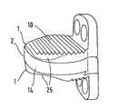
- FIGS. 1 and 2show perspective views of the whole prosthesis
- FIG. 3shows a dorsal side view of the prosthesis
- FIG. 4shows a lateral view of the prosthesis
- FIG. 5shows a top view of the outer face of the prosthesis
- FIGS. 6 to 8show different profiles of the transition surface
- FIG. 9shows a plan view of an alternative embodiment
- FIG. 10shows an enlarged representation of the connection surface and the edge contour.
- the prosthesis shown in FIGS. 1 to 8consists of two cover plates 1 and of a prosthesis core 2 .
- the inner face of one of the two cover platescan be provided as a mounting for the prosthesis core 2 , while the other cover plate forms, with the prosthesis core, a spherical slide surface 3 , for example.
- At the ventral edge of each cover platethere is a flange 4 whose dorsal face 5 is intended to bear on the ventral face of a vertebral body.
- the flangecan have securing means, for example screw holes 6 .
- Each prosthesis cover platehas a connection surface 10 for bearing on the associated vertebral body cover plate and on the bearing surface created by shaping the vertebral body, said connection surface 10 extending approximately parallel to the main plane of the cover plate. It is substantially flat, but can also have a slight curvature. It is equipped with teeth 13 and/or other means for connecting it securely in position to the bone, for example with a biologically active coating.
- Each cover plateis surrounded by a circumferential surface 14 which is approximately perpendicular to the connection surface 10 and which in the present context is designated as an edge.
- the edge 14defines the circumferential contour of the cover plate, which has an oblong shape, which can be designated as oval or as rectangular with rounded corners. It is also designated by reference number 14 in FIG. 10 .
- the prosthesis core 2has the same circumferential contour.
- the anteroposterior depth dimension 11 of the cover plates 1is smaller than their width dimension 12 , specifically for example in the ratio of three to four. An example which has proven useful has a depth of 15 mm and a width of 20 mm.
- the cover plates 1are preferably made of metal, and the core 2 of polyethylene.
- the cover plate 1 or the contour of the edge 14has a ventral face 15 , a dorsal face 16 and lateral faces 17 and 18 . Between these there extend the anteroposterior depth dimension 11 and the width dimension 12 , which in FIG. 10 are indicated as sides of an imaginary rectangle 21 circumscribing and touching the cover plate or the contour 14 of the edge. Only the part of the cover plate 1 lying behind the flange face 5 is taken into consideration here, since it is only the dimension of the part which will lie in the intervertebral space which is relevant here.
- the limit of the connection surface 10follows the contour of the edge 14 . They do not need to correspond exactly, because slight deviations in the form of roundings or bevels can be present.
- the width of theseis generally less than 3% of the width dimension 12 .
- a portion 23 of the limit 24 of the connection surface 10does not follow the contour 14 but is instead set back relative to the latter.
- the greatest extent of the set-back, in a plan view,lies between approximately 2 and 5 mm, generally of the order of 2.5 to 3.5 mm.
- the minimum distance 28 from the corner 29 of the circumscribing rectangle 21is greater than 13% and preferably greater than 15% and preferably greater than 18% of the width dimension 12 . In an illustrative embodiment which has proven useful, it is slightly more than 20% of this width.
- the set-back limit 24 relative to the contour 14is obtained by providing an oblique transition surface 25 between the limit 24 and the edge. Since the transition surface is raised in relation to the plane of the connection surface, a space is obtained below it for receiving the bone parts which have been left in the dorsolateral region upon shaping of the vertebral body surface. It will be appreciated that this space must have an adequate height for this purpose. It should be at least 1 mm at the place of the maximum height difference between the connection surface and the edge 14 .
- the transition surface 25can, for example, be convexly rounded ( FIG. 6 ) or have a straight profile ( FIG. 7 ). It can also be cut with a step ( FIG. 8 ).
- the portion 23 in which the limit 24 is set back relative to the contour 25 of the edge 14takes up approximately two thirds of the depth dimension 11 and is preferably not less than one third thereof.
- the contour of the cover platedoes not deviate from the limit of the connection surface. Slight roundings of the edges are not taken into consideration here.
- the set-back of the limit 24 of the connection surfacedecreases toward the center.
- the edge 14 in practicedoes not protrude beyond the limit 24 .
- the length of this central portionis preferably between one tenth and one third of the width dimension 12 .
- the set-back portion 23 of the limit 24 of the connection surface 10 in the dorsolateral regionhas an approximately rectilinear extent. If one compares it to a rectilinear course connecting the end points of this portion to one another, it scarcely deviates from this course. Any deviation is well below 10% of the length of this course.
- the end points of said courselie at those points where the deviation of the limit 24 of the connection surface from the circumferential contour 14 goes beyond the extent of the edge roundings otherwise provided.
- the deviation of the limit 24 from the circumferential contour 14 in the dorsolateral regionis approximately 10% of the cover plate width 12 and should be not less than 5%.
- FIG. 9A set-back of the limit of the connection surface in the dorsolateral region—corresponding to the explanations given above—is also shown in the embodiment according to FIG. 9 , which differs from that of FIGS. 1 to 8 in that the edge 14 does not extend beyond the limit of the connection surface.
- the description of the illustrative embodiment in FIGS. 1 to 8 and FIG. 10correspondingly applies to this illustrative embodiment, except that the course of the limit of the connection surface in the dorsolateral region is not compared to the circumferential contour 14 but instead to the course 14 ′, mirrored about the central transverse axis 21 , of the anterolateral circumferential contour 14 of the cover plate.
- FIG. 10illustrates the different course of the limit of the connection surface in the anterolateral region and dorsolateral region, by reference to the corners of the imaginary rectangle 30 . It will be noted that the minimum distance 28 of the dorsal corner point 29 from the limit line 24 is almost three times as great as the corresponding minimum distance 26 of the front corner point 27 . It should normally be at least 1.5 times as great.
Landscapes
- Health & Medical Sciences (AREA)
- Engineering & Computer Science (AREA)
- Biomedical Technology (AREA)
- Neurology (AREA)
- Orthopedic Medicine & Surgery (AREA)
- Cardiology (AREA)
- Oral & Maxillofacial Surgery (AREA)
- Transplantation (AREA)
- Heart & Thoracic Surgery (AREA)
- Vascular Medicine (AREA)
- Life Sciences & Earth Sciences (AREA)
- Animal Behavior & Ethology (AREA)
- General Health & Medical Sciences (AREA)
- Public Health (AREA)
- Veterinary Medicine (AREA)
- Prostheses (AREA)
Abstract
Description
Claims (9)
Priority Applications (3)
| Application Number | Priority Date | Filing Date | Title |
|---|---|---|---|
| US10/407,946US8012212B2 (en) | 2003-04-07 | 2003-04-07 | Cervical intervertebral disk prosthesis |
| US11/282,604US8147551B2 (en) | 2003-04-07 | 2005-11-21 | Method for implanting an intervertebral disk prosthesis |
| US13/438,694US8591586B2 (en) | 2003-04-07 | 2012-04-03 | Cervical intervertebral prosthesis |
Applications Claiming Priority (1)
| Application Number | Priority Date | Filing Date | Title |
|---|---|---|---|
| US10/407,946US8012212B2 (en) | 2003-04-07 | 2003-04-07 | Cervical intervertebral disk prosthesis |
Related Child Applications (1)
| Application Number | Title | Priority Date | Filing Date |
|---|---|---|---|
| US11/282,604ContinuationUS8147551B2 (en) | 2003-04-07 | 2005-11-21 | Method for implanting an intervertebral disk prosthesis |
Publications (2)
| Publication Number | Publication Date |
|---|---|
| US20040199253A1 US20040199253A1 (en) | 2004-10-07 |
| US8012212B2true US8012212B2 (en) | 2011-09-06 |
Family
ID=33097659
Family Applications (3)
| Application Number | Title | Priority Date | Filing Date |
|---|---|---|---|
| US10/407,946Expired - LifetimeUS8012212B2 (en) | 2003-04-07 | 2003-04-07 | Cervical intervertebral disk prosthesis |
| US11/282,604Active2026-05-31US8147551B2 (en) | 2003-04-07 | 2005-11-21 | Method for implanting an intervertebral disk prosthesis |
| US13/438,694Expired - LifetimeUS8591586B2 (en) | 2003-04-07 | 2012-04-03 | Cervical intervertebral prosthesis |
Family Applications After (2)
| Application Number | Title | Priority Date | Filing Date |
|---|---|---|---|
| US11/282,604Active2026-05-31US8147551B2 (en) | 2003-04-07 | 2005-11-21 | Method for implanting an intervertebral disk prosthesis |
| US13/438,694Expired - LifetimeUS8591586B2 (en) | 2003-04-07 | 2012-04-03 | Cervical intervertebral prosthesis |
Country Status (1)
| Country | Link |
|---|---|
| US (3) | US8012212B2 (en) |
Cited By (41)
| Publication number | Priority date | Publication date | Assignee | Title |
|---|---|---|---|---|
| US20090104586A1 (en)* | 2005-06-01 | 2009-04-23 | Osseous Technologies Of America | Collagen Antral Membrane Expander |
| US20110319999A1 (en)* | 2010-06-24 | 2011-12-29 | O'neil Michael J | Lateral Spondylolisthesis Reduction Cage |
| US20120191198A1 (en)* | 2003-04-07 | 2012-07-26 | Link Helmut D | Cervical intervertebral prostehsis |
| US20140324172A1 (en)* | 2006-01-24 | 2014-10-30 | Timothy G. Haines | Dynamic Spinal Implants Incorporating Cartilage Bearing Graft Material |
| US9226764B2 (en) | 2012-03-06 | 2016-01-05 | DePuy Synthes Products, Inc. | Conformable soft tissue removal instruments |
| US9610168B2 (en) | 2014-05-12 | 2017-04-04 | Integra Lifesciences Corporation | Total ankle replacement prosthesis |
| US9931224B2 (en) | 2009-11-05 | 2018-04-03 | DePuy Synthes Products, Inc. | Self-pivoting spinal implant and associated instrumentation |
| US10022245B2 (en) | 2012-12-17 | 2018-07-17 | DePuy Synthes Products, Inc. | Polyaxial articulating instrument |
| US10321833B2 (en) | 2016-10-05 | 2019-06-18 | Innovative Surgical Solutions. | Neural locating method |
| US10376208B2 (en) | 2013-09-20 | 2019-08-13 | Innovative Surgical Solutions, Llc | Nerve mapping system |
| US10376209B2 (en) | 2013-09-20 | 2019-08-13 | Innovative Surgical Solutions, Llc | Neural locating method |
| US10449002B2 (en) | 2013-09-20 | 2019-10-22 | Innovative Surgical Solutions, Llc | Method of mapping a nerve |
| US10478097B2 (en) | 2013-08-13 | 2019-11-19 | Innovative Surgical Solutions | Neural event detection |
| US10478096B2 (en) | 2013-08-13 | 2019-11-19 | Innovative Surgical Solutions. | Neural event detection |
| US10869616B2 (en) | 2018-06-01 | 2020-12-22 | DePuy Synthes Products, Inc. | Neural event detection |
| US10870002B2 (en) | 2018-10-12 | 2020-12-22 | DePuy Synthes Products, Inc. | Neuromuscular sensing device with multi-sensor array |
| US10966843B2 (en) | 2017-07-18 | 2021-04-06 | DePuy Synthes Products, Inc. | Implant inserters and related methods |
| US11045331B2 (en) | 2017-08-14 | 2021-06-29 | DePuy Synthes Products, Inc. | Intervertebral implant inserters and related methods |
| US11344424B2 (en) | 2017-06-14 | 2022-05-31 | Medos International Sarl | Expandable intervertebral implant and related methods |
| US11369490B2 (en) | 2011-03-22 | 2022-06-28 | DePuy Synthes Products, Inc. | Universal trial for lateral cages |
| US11399777B2 (en) | 2019-09-27 | 2022-08-02 | DePuy Synthes Products, Inc. | Intraoperative neural monitoring system and method |
| US11426290B2 (en) | 2015-03-06 | 2022-08-30 | DePuy Synthes Products, Inc. | Expandable intervertebral implant, system, kit and method |
| US11432942B2 (en) | 2006-12-07 | 2022-09-06 | DePuy Synthes Products, Inc. | Intervertebral implant |
| US11446155B2 (en) | 2017-05-08 | 2022-09-20 | Medos International Sarl | Expandable cage |
| US11446156B2 (en) | 2018-10-25 | 2022-09-20 | Medos International Sarl | Expandable intervertebral implant, inserter instrument, and related methods |
| US11452607B2 (en) | 2010-10-11 | 2022-09-27 | DePuy Synthes Products, Inc. | Expandable interspinous process spacer implant |
| US11497619B2 (en) | 2013-03-07 | 2022-11-15 | DePuy Synthes Products, Inc. | Intervertebral implant |
| US11510788B2 (en) | 2016-06-28 | 2022-11-29 | Eit Emerging Implant Technologies Gmbh | Expandable, angularly adjustable intervertebral cages |
| US11596523B2 (en) | 2016-06-28 | 2023-03-07 | Eit Emerging Implant Technologies Gmbh | Expandable and angularly adjustable articulating intervertebral cages |
| US11602438B2 (en) | 2008-04-05 | 2023-03-14 | DePuy Synthes Products, Inc. | Expandable intervertebral implant |
| US11622868B2 (en) | 2007-06-26 | 2023-04-11 | DePuy Synthes Products, Inc. | Highly lordosed fusion cage |
| US11654033B2 (en) | 2010-06-29 | 2023-05-23 | DePuy Synthes Products, Inc. | Distractible intervertebral implant |
| US11737881B2 (en) | 2008-01-17 | 2023-08-29 | DePuy Synthes Products, Inc. | Expandable intervertebral implant and associated method of manufacturing the same |
| US11752009B2 (en) | 2021-04-06 | 2023-09-12 | Medos International Sarl | Expandable intervertebral fusion cage |
| US11806245B2 (en) | 2020-03-06 | 2023-11-07 | Eit Emerging Implant Technologies Gmbh | Expandable intervertebral implant |
| US11850160B2 (en) | 2021-03-26 | 2023-12-26 | Medos International Sarl | Expandable lordotic intervertebral fusion cage |
| US11872139B2 (en) | 2010-06-24 | 2024-01-16 | DePuy Synthes Products, Inc. | Enhanced cage insertion assembly |
| USRE49973E1 (en) | 2013-02-28 | 2024-05-21 | DePuy Synthes Products, Inc. | Expandable intervertebral implant, system, kit and method |
| US12090064B2 (en) | 2022-03-01 | 2024-09-17 | Medos International Sarl | Stabilization members for expandable intervertebral implants, and related systems and methods |
| US12097124B2 (en) | 2009-03-30 | 2024-09-24 | DePuy Synthes Products, Inc. | Zero profile spinal fusion cage |
| US12440346B2 (en) | 2023-03-31 | 2025-10-14 | DePuy Synthes Products, Inc. | Expandable intervertebral implant |
Families Citing this family (35)
| Publication number | Priority date | Publication date | Assignee | Title |
|---|---|---|---|---|
| US6730127B2 (en)* | 2000-07-10 | 2004-05-04 | Gary K. Michelson | Flanged interbody spinal fusion implants |
| US6562073B2 (en)* | 2001-02-06 | 2003-05-13 | Sdgi Holding, Inc. | Spinal bone implant |
| ITFI20030084A1 (en)* | 2003-03-28 | 2004-09-29 | Cousin Biotech S A S | INTERLAMINARY VERTEBRAL PROSTHESIS |
| BRPI0409091A (en)* | 2003-04-07 | 2006-04-11 | Cervitech Inc | intervertebral joint prosthesis for the cervical spine |
| GB2410189A (en)* | 2004-01-23 | 2005-07-27 | Corin Ltd | Intervertebral disc prosthesis |
| EP2113227B1 (en) | 2004-02-04 | 2015-07-29 | LDR Medical | Intervertebral disc prosthesis |
| US8172904B2 (en) | 2004-06-30 | 2012-05-08 | Synergy Disc Replacement, Inc. | Artificial spinal disc |
| MXPA06014714A (en) | 2004-06-30 | 2007-06-22 | Synergy Disc Replacement Inc | Artificial spinal disc. |
| WO2006042487A1 (en)* | 2004-10-18 | 2006-04-27 | Buettner-Janz Karin | Intervertebral disc endoprosthesis having cylindrical articulation surfaces |
| WO2006042486A1 (en)* | 2004-10-18 | 2006-04-27 | Buettner-Janz Karin | Intervertebral disk endoprosthesis having a motion-adapted edge for the lumbar and cervical spine |
| GB0508678D0 (en) | 2005-04-28 | 2005-06-08 | Cope Aiden | Motion segment intervertebral disc prosthesis |
| FR2891135B1 (en) | 2005-09-23 | 2008-09-12 | Ldr Medical Sarl | INTERVERTEBRAL DISC PROSTHESIS |
| JP5167494B2 (en)* | 2005-10-10 | 2013-03-21 | ドナ・ジーン・カーヴァー | Artificial intervertebral disc replacement system and method |
| US9039768B2 (en) | 2006-12-22 | 2015-05-26 | Medos International Sarl | Composite vertebral spacers and instrument |
| US20090248092A1 (en) | 2008-03-26 | 2009-10-01 | Jonathan Bellas | Posterior Intervertebral Disc Inserter and Expansion Techniques |
| WO2010096773A1 (en)* | 2009-02-20 | 2010-08-26 | Spartan Cage Holding, Llc | Interbody fusion system with intervertebral implant retention assembly |
| WO2011008864A1 (en)* | 2009-07-14 | 2011-01-20 | Life Spine, Inc. | Combined interbody and plate assemblies |
| US8945225B2 (en)* | 2009-07-20 | 2015-02-03 | Warsaw, Orthopedic, Inc. | Prosthetic spinal disc system |
| US9393129B2 (en) | 2009-12-10 | 2016-07-19 | DePuy Synthes Products, Inc. | Bellows-like expandable interbody fusion cage |
| US20120078372A1 (en) | 2010-09-23 | 2012-03-29 | Thomas Gamache | Novel implant inserter having a laterally-extending dovetail engagement feature |
| US20120078373A1 (en) | 2010-09-23 | 2012-03-29 | Thomas Gamache | Stand alone intervertebral fusion device |
| US11529241B2 (en) | 2010-09-23 | 2022-12-20 | DePuy Synthes Products, Inc. | Fusion cage with in-line single piece fixation |
| US9277946B2 (en) | 2011-09-06 | 2016-03-08 | Amendia, Inc. | Spinal fusion system |
| US9248028B2 (en) | 2011-09-16 | 2016-02-02 | DePuy Synthes Products, Inc. | Removable, bone-securing cover plate for intervertebral fusion cage |
| US9271836B2 (en) | 2012-03-06 | 2016-03-01 | DePuy Synthes Products, Inc. | Nubbed plate |
| US20130261746A1 (en)* | 2012-03-28 | 2013-10-03 | Linares Medical Devices, Llc | Implantable inter-vertebral disk having upper and lower layers of a metal exhibiting bone fusing characteristics and which sandwich therebetween a soft plastic cushioning disc for providing dynamic properties mimicking that of a natural inter-vertebral disc |
| US10182921B2 (en) | 2012-11-09 | 2019-01-22 | DePuy Synthes Products, Inc. | Interbody device with opening to allow packing graft and other biologics |
| US11160666B2 (en)* | 2014-05-15 | 2021-11-02 | Globus Medical, Inc. | Laterally insertable intervertebral spinal implant |
| US9968461B2 (en)* | 2014-05-15 | 2018-05-15 | Globus Medical, Inc. | Standalone interbody implants |
| US20160270928A1 (en)* | 2015-03-18 | 2016-09-22 | Baui Biotech Co., Ltd. | Spinal spacer |
| US9956087B2 (en)* | 2015-07-17 | 2018-05-01 | Globus Medical, Inc | Intervertebral spacer and plate |
| US10940016B2 (en) | 2017-07-05 | 2021-03-09 | Medos International Sarl | Expandable intervertebral fusion cage |
| US10874521B2 (en) | 2017-11-07 | 2020-12-29 | Uki Llc | Artificial intervertebral implant |
| US10258482B1 (en) | 2017-11-07 | 2019-04-16 | Uki Llc | Artificial intervertebral implant |
| CN114392018B (en)* | 2022-02-25 | 2024-11-15 | 郝定均 | Atlantoaxial mass arthroplasty prosthesis |
Citations (96)
| Publication number | Priority date | Publication date | Assignee | Title |
|---|---|---|---|---|
| EP0179695A1 (en) | 1984-09-26 | 1986-04-30 | Pierre Kehr | Vertebral prosthesis, in particular for cervical vertebrae |
| WO1990000037A1 (en) | 1988-06-28 | 1990-01-11 | Michelson Gary K | Artificial spinal fusion implants |
| US4911718A (en) | 1988-06-10 | 1990-03-27 | University Of Medicine & Dentistry Of N.J. | Functional and biocompatible intervertebral disc spacer |
| US5002576A (en)* | 1988-06-06 | 1991-03-26 | Mecron Medizinische Produkte Gmbh | Intervertebral disk endoprosthesis |
| WO1991013598A1 (en) | 1990-03-07 | 1991-09-19 | J.B.S. S.A. | Prosthesis for intervertebral discs and instruments for its implantation |
| US5171281A (en) | 1988-08-18 | 1992-12-15 | University Of Medicine & Dentistry Of New Jersey | Functional and biocompatible intervertebral disc spacer containing elastomeric material of varying hardness |
| US5236460A (en) | 1990-02-12 | 1993-08-17 | Midas Rex Pneumatic Tools, Inc. | Vertebral body prosthesis |
| DE4213771C1 (en) | 1992-04-27 | 1993-09-30 | Eska Medical Gmbh & Co | Intervertebral disc prosthesis |
| US5258031A (en) | 1992-01-06 | 1993-11-02 | Danek Medical | Intervertebral disk arthroplasty |
| FR2694882A1 (en) | 1992-08-24 | 1994-02-25 | Sofamor | Intervertebral disc prosthesis. |
| US5290312A (en) | 1991-09-03 | 1994-03-01 | Alphatec | Artificial vertebral body |
| DE4423826A1 (en) | 1993-07-07 | 1995-01-12 | Asahi Optical Co Ltd | Ceramic vertebral prosthesis |
| US5401269A (en)* | 1992-03-13 | 1995-03-28 | Waldemar Link Gmbh & Co. | Intervertebral disc endoprosthesis |
| US5425773A (en) | 1992-01-06 | 1995-06-20 | Danek Medical, Inc. | Intervertebral disk arthroplasty device |
| FR2718635A1 (en) | 1994-04-15 | 1995-10-20 | Axcyl Medical | Vertebral cervical prosthesis |
| EP0699426A1 (en) | 1994-09-05 | 1996-03-06 | Medinov S.A. | Sliding intervertebral prosthesis, especially cervical intervertebral prosthesis |
| US5507816A (en) | 1991-12-04 | 1996-04-16 | Customflex Limited | Spinal vertebrae implants |
| US5514180A (en) | 1994-01-14 | 1996-05-07 | Heggeness; Michael H. | Prosthetic intervertebral devices |
| US5534030A (en) | 1993-02-09 | 1996-07-09 | Acromed Corporation | Spine disc |
| EP0747025A1 (en) | 1995-06-07 | 1996-12-11 | SMITH & NEPHEW RICHARDS, INC. | Low wear artificial spinal disc |
| WO1997020526A1 (en) | 1995-12-08 | 1997-06-12 | Bray Robert S Jr | Anterior stabilization device |
| EP0820740A1 (en) | 1996-07-22 | 1998-01-28 | Vincent Bryan | Human spinal disc prosthesis |
| WO1999008627A1 (en) | 1997-08-13 | 1999-02-25 | Cambridge Scientific, Inc. | Resorbable interbody spinal fusion devices |
| US5888227A (en) | 1995-10-20 | 1999-03-30 | Synthes (U.S.A.) | Inter-vertebral implant |
| US5895428A (en) | 1996-11-01 | 1999-04-20 | Berry; Don | Load bearing spinal joint implant |
| CN2333369Y (en) | 1998-05-29 | 1999-08-18 | 中山医科大学孙逸仙纪念医院 | Artificial lumbar intervertebral disc |
| US5989291A (en) | 1998-02-26 | 1999-11-23 | Third Millennium Engineering, Llc | Intervertebral spacer device |
| WO1999065425A2 (en) | 1998-06-17 | 1999-12-23 | Surgical Dynamics, Inc. | Artificial intervertebral disc |
| US6063121A (en) | 1998-07-29 | 2000-05-16 | Xavier; Ravi | Vertebral body prosthesis |
| US6083228A (en) | 1998-06-09 | 2000-07-04 | Michelson; Gary K. | Device and method for preparing a space between adjacent vertebrae to receive an insert |
| US6113637A (en)* | 1998-10-22 | 2000-09-05 | Sofamor Danek Holdings, Inc. | Artificial intervertebral joint permitting translational and rotational motion |
| US6162252A (en) | 1997-12-12 | 2000-12-19 | Depuy Acromed, Inc. | Artificial spinal disc |
| WO2001001893A1 (en) | 1999-07-02 | 2001-01-11 | Spine Solutions Inc. | Intervertebral implant |
| US6190410B1 (en) | 1999-04-29 | 2001-02-20 | Bausch & Lomb Surgical, Inc. | Intraocular lenses |
| US6228118B1 (en) | 1997-08-04 | 2001-05-08 | Gordon, Maya, Roberts And Thomas, Number 1, Llc | Multiple axis intervertebral prosthesis |
| US6235059B1 (en)* | 1996-04-03 | 2001-05-22 | Scient'x (Societe A Responsabilite Limitee) | Intersomatic setting and fusion system |
| EP1103237A2 (en) | 1999-11-24 | 2001-05-30 | DePuy Acromed, Inc. | Prosthetic implant element |
| WO2001054629A1 (en) | 2000-01-31 | 2001-08-02 | Spineco | Spinal fusion implant |
| US20010016774A1 (en) | 1998-10-20 | 2001-08-23 | Bresina Stephen J. | Strain regulating fusion cage for spinal fusion surgery |
| US20010016773A1 (en)* | 1998-10-15 | 2001-08-23 | Hassan Serhan | Spinal disc |
| US20010032017A1 (en) | 1999-12-30 | 2001-10-18 | Alfaro Arthur A. | Intervertebral implants |
| US20010034553A1 (en) | 2000-02-04 | 2001-10-25 | Michelson Gary Karlin | Expandable push-in arcuate interbody spinal fusion implant with tapered configuration during insertion |
| WO2001091686A1 (en) | 2000-05-30 | 2001-12-06 | Lin Paul S | Implant for placement between cervical vertebrae |
| WO2002011650A2 (en) | 2000-08-08 | 2002-02-14 | Sdgi Holdings, Inc. | Implantable joint prosthesis |
| FR2813519A1 (en)* | 2000-09-07 | 2002-03-08 | Eurosurgical | Intersomatic spinal implant, has supple structure to hold graft under pressure against surfaces of adjacent vertebrae |
| US20020045943A1 (en) | 2000-10-17 | 2002-04-18 | Uk Chang Jong | Prosthetic device for correcting deformity of spine |
| US6375682B1 (en) | 2001-08-06 | 2002-04-23 | Lewis W. Fleischmann | Collapsible, rotatable and expandable spinal hydraulic prosthetic device |
| US20020068977A1 (en) | 2000-12-05 | 2002-06-06 | Jackson Roger P. | Anterior variable expandable fusion cage |
| US20020107574A1 (en) | 2000-11-13 | 2002-08-08 | Boehm Frank H. | Device and method for lumbar interbody fusion |
| US6436140B1 (en) | 1998-08-28 | 2002-08-20 | Sofamor S.N.C. | Expandable interbody fusion cage and method for insertion |
| US6436142B1 (en) | 1998-12-14 | 2002-08-20 | Phoenix Biomedical Corp. | System for stabilizing the vertebral column including deployment instruments and variable expansion inserts therefor |
| US6443989B1 (en) | 2000-12-04 | 2002-09-03 | Roger P. Jackson | Posterior expandable fusion cage |
| US20020128716A1 (en) | 1999-07-26 | 2002-09-12 | Howard Cohen | Spinal surgical prosthesis |
| US6454807B1 (en) | 2000-11-30 | 2002-09-24 | Roger P. Jackson | Articulated expandable spinal fusion cage system |
| US20020143399A1 (en) | 2001-04-02 | 2002-10-03 | Ulrich Gmbh & Co. Kg | Anchorable vertebral implant |
| US20020169508A1 (en) | 1998-06-18 | 2002-11-14 | Pioneer Laboratories, Inc. | Spinal fixation system |
| US20020177898A1 (en)* | 1997-04-25 | 2002-11-28 | Yves Crozet | Two part intersomatic implant |
| US20020193880A1 (en) | 1999-11-24 | 2002-12-19 | Robert Fraser | Anterior lumbar interbody fusion cage with locking plate |
| US6517580B1 (en)* | 2000-03-03 | 2003-02-11 | Scient'x Societe A Responsabilite Limited | Disk prosthesis for cervical vertebrae |
| US20030069586A1 (en) | 2001-07-16 | 2003-04-10 | Errico Joseph P. | Instrumentation and methods for use in implanting an artificial intervertebral disc |
| US20030069643A1 (en)* | 2001-07-16 | 2003-04-10 | Ralph James D. | Tension bearing artificial disc providing a centroid of motion centrally located within an intervertebral space |
| US6572653B1 (en) | 2001-12-07 | 2003-06-03 | Rush E. Simonson | Vertebral implant adapted for posterior insertion |
| US20030125739A1 (en) | 2001-12-12 | 2003-07-03 | Bagga Charanpreet S. | Bioactive spinal implants and method of manufacture thereof |
| US20030130739A1 (en) | 2001-10-17 | 2003-07-10 | Medicinelodge, Inc. | Adjustable bone fusion implant and method |
| WO2003063727A2 (en) | 2001-11-26 | 2003-08-07 | Sdgi Holdings, Inc. | Implantable joint prosthesis and associated instrumentation |
| US6610092B2 (en) | 2001-10-18 | 2003-08-26 | Spinefore, Inc. | Intervertebral spacer device having a slotted partial circular domed arch strip spring |
| US6610093B1 (en) | 2000-07-28 | 2003-08-26 | Perumala Corporation | Method and apparatus for stabilizing adjacent vertebrae |
| US20030167091A1 (en) | 2002-03-04 | 2003-09-04 | Scharf Michael S. | Spinal fixation device |
| EP1344508A1 (en) | 2002-03-12 | 2003-09-17 | Waldemar Link (GmbH & Co.) | Intervertebral prosthesis especially for the cervical spine |
| EP1344507A1 (en) | 2002-03-12 | 2003-09-17 | Waldemar Link (GmbH & Co.) | Intervertebral prosthesis for the cervical spine |
| WO2003075803A1 (en) | 2002-03-12 | 2003-09-18 | Cervitech Inc. | Intravertebral prosthesis |
| US20030176923A1 (en) | 2002-03-12 | 2003-09-18 | Waldemar Link Gmbh & Co. | Intervertebral prosthesis |
| US20030181981A1 (en) | 2000-05-11 | 2003-09-25 | Jean-Philippe Lemaire | Anterior lumbar interbody implant |
| US20030191534A1 (en) | 2000-03-10 | 2003-10-09 | Guy Viart | Intervertebral disc prosthesis |
| US20030204261A1 (en) | 2002-04-25 | 2003-10-30 | Lukas Eisermann | Articular disc prosthesis and method for implanting the same |
| US20030208273A1 (en) | 2002-01-09 | 2003-11-06 | Lukas Eisermann | Intervertebral prosthetic joint |
| US20030233146A1 (en) | 2002-06-18 | 2003-12-18 | Alexander Grinberg | Intervertebral disc |
| US20040010316A1 (en) | 2002-03-30 | 2004-01-15 | Lytton William | Intervertebral device and method of use |
| US6685742B1 (en) | 2002-11-12 | 2004-02-03 | Roger P. Jackson | Articulated anterior expandable spinal fusion cage system |
| US20040068318A1 (en) | 2002-10-02 | 2004-04-08 | Coates Bradley J. | Modular intervertebral prosthesis system |
| US20040073310A1 (en) | 2002-10-09 | 2004-04-15 | Missoum Moumene | Intervertebral motion disc having articulation and shock absorption |
| US6733532B1 (en) | 1998-12-11 | 2004-05-11 | Stryker Spine | Intervertebral disc prosthesis with improved mechanical behavior |
| US20040117021A1 (en) | 2002-09-12 | 2004-06-17 | Lutz Biedermann | Invertebral disk prosthesis |
| US20040133281A1 (en) | 2002-12-17 | 2004-07-08 | Khandkar Ashok C. | Total disc implant |
| US20040153160A1 (en) | 2002-10-30 | 2004-08-05 | Carrasco Mauricio Rodolfo | Implant for vertebral replacement and restoration of the normal spinal curvature |
| US20040176850A1 (en) | 2003-03-06 | 2004-09-09 | Rafail Zubok | Cervical disc replacement |
| US6800092B1 (en) | 1999-02-26 | 2004-10-05 | Lytton A. Williams | Method and apparatus for intervertebral implant anchorage |
| US20040199253A1 (en) | 2003-04-07 | 2004-10-07 | Cervitech, Inc. | Cervical intervertebral disk prosthesis |
| US20040254644A1 (en)* | 2002-10-21 | 2004-12-16 | Taylor Brett Allison | Intervertebral disk prosthesis |
| US6986789B2 (en) | 2003-08-22 | 2006-01-17 | Aesculap Ag & Co. Kg | Intervertebral implant |
| US20060085077A1 (en) | 2004-10-18 | 2006-04-20 | Ebi, L.P. | Intervertebral implant and associated method |
| US20060116768A1 (en) | 2002-10-31 | 2006-06-01 | Krueger David J | Movable disc implant |
| US7217291B2 (en) | 2003-12-08 | 2007-05-15 | St. Francis Medical Technologies, Inc. | System and method for replacing degenerated spinal disks |
| US7276082B2 (en) | 2003-09-10 | 2007-10-02 | Warsaw Orthopedic, Inc. | Artificial spinal discs and associated implantation and revision methods |
| US7485134B2 (en) | 2001-12-07 | 2009-02-03 | Simonson Rush E | Vertebral implants adapted for posterior insertion |
| US7550010B2 (en) | 2004-01-09 | 2009-06-23 | Warsaw Orthopedic, Inc. | Spinal arthroplasty device and method |
Family Cites Families (3)
| Publication number | Priority date | Publication date | Assignee | Title |
|---|---|---|---|---|
| US5425733A (en)* | 1992-02-19 | 1995-06-20 | Arthrex, Inc. | Interference screw with rounded back end and cannulated sheath for endosteal fixation of ligaments |
| US7042902B2 (en)* | 1997-10-08 | 2006-05-09 | Bandwidth Technology Corp. | Techniques for communicating information using prime-frequency waveform mapping |
| US7231259B2 (en)* | 2002-10-04 | 2007-06-12 | Pacesetter, Inc. | Body implantable lead comprising electrically conductive polymer conductors |
- 2003
- 2003-04-07USUS10/407,946patent/US8012212B2/ennot_activeExpired - Lifetime
- 2005
- 2005-11-21USUS11/282,604patent/US8147551B2/enactiveActive
- 2012
- 2012-04-03USUS13/438,694patent/US8591586B2/ennot_activeExpired - Lifetime
Patent Citations (109)
| Publication number | Priority date | Publication date | Assignee | Title |
|---|---|---|---|---|
| EP0179695A1 (en) | 1984-09-26 | 1986-04-30 | Pierre Kehr | Vertebral prosthesis, in particular for cervical vertebrae |
| US5002576A (en)* | 1988-06-06 | 1991-03-26 | Mecron Medizinische Produkte Gmbh | Intervertebral disk endoprosthesis |
| US4911718A (en) | 1988-06-10 | 1990-03-27 | University Of Medicine & Dentistry Of N.J. | Functional and biocompatible intervertebral disc spacer |
| WO1990000037A1 (en) | 1988-06-28 | 1990-01-11 | Michelson Gary K | Artificial spinal fusion implants |
| US5171281A (en) | 1988-08-18 | 1992-12-15 | University Of Medicine & Dentistry Of New Jersey | Functional and biocompatible intervertebral disc spacer containing elastomeric material of varying hardness |
| US5236460A (en) | 1990-02-12 | 1993-08-17 | Midas Rex Pneumatic Tools, Inc. | Vertebral body prosthesis |
| EP0471821A1 (en) | 1990-03-07 | 1992-02-26 | Jbs Sa | PROSTHESIS FOR INTERVERTEBRAL DISCS AND ITS IMPLEMENTATION INSTRUMENTS. |
| WO1991013598A1 (en) | 1990-03-07 | 1991-09-19 | J.B.S. S.A. | Prosthesis for intervertebral discs and instruments for its implantation |
| US5290312A (en) | 1991-09-03 | 1994-03-01 | Alphatec | Artificial vertebral body |
| US5507816A (en) | 1991-12-04 | 1996-04-16 | Customflex Limited | Spinal vertebrae implants |
| US5258031A (en) | 1992-01-06 | 1993-11-02 | Danek Medical | Intervertebral disk arthroplasty |
| US5562738A (en) | 1992-01-06 | 1996-10-08 | Danek Medical, Inc. | Intervertebral disk arthroplasty device |
| US5425773A (en) | 1992-01-06 | 1995-06-20 | Danek Medical, Inc. | Intervertebral disk arthroplasty device |
| US5401269A (en)* | 1992-03-13 | 1995-03-28 | Waldemar Link Gmbh & Co. | Intervertebral disc endoprosthesis |
| DE4213771C1 (en) | 1992-04-27 | 1993-09-30 | Eska Medical Gmbh & Co | Intervertebral disc prosthesis |
| FR2694882A1 (en) | 1992-08-24 | 1994-02-25 | Sofamor | Intervertebral disc prosthesis. |
| US5676701A (en) | 1993-01-14 | 1997-10-14 | Smith & Nephew, Inc. | Low wear artificial spinal disc |
| US5534030A (en) | 1993-02-09 | 1996-07-09 | Acromed Corporation | Spine disc |
| DE4423826A1 (en) | 1993-07-07 | 1995-01-12 | Asahi Optical Co Ltd | Ceramic vertebral prosthesis |
| US5645596A (en) | 1993-07-07 | 1997-07-08 | Asahi Kogaku Kogyo Kabushiki Kaisha | Ceramic vertebrae prosthesis |
| US5514180A (en) | 1994-01-14 | 1996-05-07 | Heggeness; Michael H. | Prosthetic intervertebral devices |
| FR2718635A1 (en) | 1994-04-15 | 1995-10-20 | Axcyl Medical | Vertebral cervical prosthesis |
| EP0699426A1 (en) | 1994-09-05 | 1996-03-06 | Medinov S.A. | Sliding intervertebral prosthesis, especially cervical intervertebral prosthesis |
| US6156067A (en) | 1994-11-14 | 2000-12-05 | Spinal Dynamics Corporation | Human spinal disc prosthesis |
| EP0747025A1 (en) | 1995-06-07 | 1996-12-11 | SMITH & NEPHEW RICHARDS, INC. | Low wear artificial spinal disc |
| US5888227A (en) | 1995-10-20 | 1999-03-30 | Synthes (U.S.A.) | Inter-vertebral implant |
| WO1997020526A1 (en) | 1995-12-08 | 1997-06-12 | Bray Robert S Jr | Anterior stabilization device |
| US6235059B1 (en)* | 1996-04-03 | 2001-05-22 | Scient'x (Societe A Responsabilite Limitee) | Intersomatic setting and fusion system |
| EP1166725A2 (en) | 1996-07-22 | 2002-01-02 | Spinal Dynamics Corporation | Human spinal disc prosthesis |
| EP0820740A1 (en) | 1996-07-22 | 1998-01-28 | Vincent Bryan | Human spinal disc prosthesis |
| US5895428A (en) | 1996-11-01 | 1999-04-20 | Berry; Don | Load bearing spinal joint implant |
| US20020177898A1 (en)* | 1997-04-25 | 2002-11-28 | Yves Crozet | Two part intersomatic implant |
| US6228118B1 (en) | 1997-08-04 | 2001-05-08 | Gordon, Maya, Roberts And Thomas, Number 1, Llc | Multiple axis intervertebral prosthesis |
| WO1999008627A1 (en) | 1997-08-13 | 1999-02-25 | Cambridge Scientific, Inc. | Resorbable interbody spinal fusion devices |
| US20010008980A1 (en) | 1997-08-13 | 2001-07-19 | Cambridge Scientific, Inc. | Resorbable interbody spinal fusion devices |
| US6162252A (en) | 1997-12-12 | 2000-12-19 | Depuy Acromed, Inc. | Artificial spinal disc |
| US5989291A (en) | 1998-02-26 | 1999-11-23 | Third Millennium Engineering, Llc | Intervertebral spacer device |
| CN2333369Y (en) | 1998-05-29 | 1999-08-18 | 中山医科大学孙逸仙纪念医院 | Artificial lumbar intervertebral disc |
| US6083228A (en) | 1998-06-09 | 2000-07-04 | Michelson; Gary K. | Device and method for preparing a space between adjacent vertebrae to receive an insert |
| US6296664B1 (en) | 1998-06-17 | 2001-10-02 | Surgical Dynamics, Inc. | Artificial intervertebral disc |
| WO1999065425A2 (en) | 1998-06-17 | 1999-12-23 | Surgical Dynamics, Inc. | Artificial intervertebral disc |
| US20020169508A1 (en) | 1998-06-18 | 2002-11-14 | Pioneer Laboratories, Inc. | Spinal fixation system |
| US6063121A (en) | 1998-07-29 | 2000-05-16 | Xavier; Ravi | Vertebral body prosthesis |
| US6436140B1 (en) | 1998-08-28 | 2002-08-20 | Sofamor S.N.C. | Expandable interbody fusion cage and method for insertion |
| US20010016773A1 (en)* | 1998-10-15 | 2001-08-23 | Hassan Serhan | Spinal disc |
| US20010016774A1 (en) | 1998-10-20 | 2001-08-23 | Bresina Stephen J. | Strain regulating fusion cage for spinal fusion surgery |
| US6395035B2 (en) | 1998-10-20 | 2002-05-28 | Synthes (U.S.A.) | Strain regulating fusion cage for spinal fusion surgery |
| US6113637A (en)* | 1998-10-22 | 2000-09-05 | Sofamor Danek Holdings, Inc. | Artificial intervertebral joint permitting translational and rotational motion |
| US6733532B1 (en) | 1998-12-11 | 2004-05-11 | Stryker Spine | Intervertebral disc prosthesis with improved mechanical behavior |
| US6436142B1 (en) | 1998-12-14 | 2002-08-20 | Phoenix Biomedical Corp. | System for stabilizing the vertebral column including deployment instruments and variable expansion inserts therefor |
| US6800092B1 (en) | 1999-02-26 | 2004-10-05 | Lytton A. Williams | Method and apparatus for intervertebral implant anchorage |
| US6190410B1 (en) | 1999-04-29 | 2001-02-20 | Bausch & Lomb Surgical, Inc. | Intraocular lenses |
| US20050085917A1 (en) | 1999-07-02 | 2005-04-21 | Thierry Marnay | Intervertebral implant |
| WO2001001893A1 (en) | 1999-07-02 | 2001-01-11 | Spine Solutions Inc. | Intervertebral implant |
| US20020128716A1 (en) | 1999-07-26 | 2002-09-12 | Howard Cohen | Spinal surgical prosthesis |
| US20020193880A1 (en) | 1999-11-24 | 2002-12-19 | Robert Fraser | Anterior lumbar interbody fusion cage with locking plate |
| EP1103237A2 (en) | 1999-11-24 | 2001-05-30 | DePuy Acromed, Inc. | Prosthetic implant element |
| US20010032017A1 (en) | 1999-12-30 | 2001-10-18 | Alfaro Arthur A. | Intervertebral implants |
| WO2001054629A1 (en) | 2000-01-31 | 2001-08-02 | Spineco | Spinal fusion implant |
| US20010034553A1 (en) | 2000-02-04 | 2001-10-25 | Michelson Gary Karlin | Expandable push-in arcuate interbody spinal fusion implant with tapered configuration during insertion |
| US6517580B1 (en)* | 2000-03-03 | 2003-02-11 | Scient'x Societe A Responsabilite Limited | Disk prosthesis for cervical vertebrae |
| US20030191534A1 (en) | 2000-03-10 | 2003-10-09 | Guy Viart | Intervertebral disc prosthesis |
| US20030181981A1 (en) | 2000-05-11 | 2003-09-25 | Jean-Philippe Lemaire | Anterior lumbar interbody implant |
| WO2001091686A1 (en) | 2000-05-30 | 2001-12-06 | Lin Paul S | Implant for placement between cervical vertebrae |
| US6610093B1 (en) | 2000-07-28 | 2003-08-26 | Perumala Corporation | Method and apparatus for stabilizing adjacent vertebrae |
| US20020128715A1 (en) | 2000-08-08 | 2002-09-12 | Vincent Bryan | Implantable joint prosthesis |
| WO2002011650A2 (en) | 2000-08-08 | 2002-02-14 | Sdgi Holdings, Inc. | Implantable joint prosthesis |
| FR2813519A1 (en)* | 2000-09-07 | 2002-03-08 | Eurosurgical | Intersomatic spinal implant, has supple structure to hold graft under pressure against surfaces of adjacent vertebrae |
| US20020045943A1 (en) | 2000-10-17 | 2002-04-18 | Uk Chang Jong | Prosthetic device for correcting deformity of spine |
| US20020107574A1 (en) | 2000-11-13 | 2002-08-08 | Boehm Frank H. | Device and method for lumbar interbody fusion |
| US6730126B2 (en) | 2000-11-13 | 2004-05-04 | Frank H. Boehm, Jr. | Device and method for lumbar interbody fusion |
| US6454807B1 (en) | 2000-11-30 | 2002-09-24 | Roger P. Jackson | Articulated expandable spinal fusion cage system |
| US6443989B1 (en) | 2000-12-04 | 2002-09-03 | Roger P. Jackson | Posterior expandable fusion cage |
| US20020068977A1 (en) | 2000-12-05 | 2002-06-06 | Jackson Roger P. | Anterior variable expandable fusion cage |
| US20020143399A1 (en) | 2001-04-02 | 2002-10-03 | Ulrich Gmbh & Co. Kg | Anchorable vertebral implant |
| US6805714B2 (en) | 2001-04-02 | 2004-10-19 | Ulrich Gmbh & Co. Kg | Anchorable vertebral implant |
| US20030069586A1 (en) | 2001-07-16 | 2003-04-10 | Errico Joseph P. | Instrumentation and methods for use in implanting an artificial intervertebral disc |
| US20030069643A1 (en)* | 2001-07-16 | 2003-04-10 | Ralph James D. | Tension bearing artificial disc providing a centroid of motion centrally located within an intervertebral space |
| US6375682B1 (en) | 2001-08-06 | 2002-04-23 | Lewis W. Fleischmann | Collapsible, rotatable and expandable spinal hydraulic prosthetic device |
| US20030130739A1 (en) | 2001-10-17 | 2003-07-10 | Medicinelodge, Inc. | Adjustable bone fusion implant and method |
| US6610092B2 (en) | 2001-10-18 | 2003-08-26 | Spinefore, Inc. | Intervertebral spacer device having a slotted partial circular domed arch strip spring |
| WO2003063727A2 (en) | 2001-11-26 | 2003-08-07 | Sdgi Holdings, Inc. | Implantable joint prosthesis and associated instrumentation |
| US7485134B2 (en) | 2001-12-07 | 2009-02-03 | Simonson Rush E | Vertebral implants adapted for posterior insertion |
| US6572653B1 (en) | 2001-12-07 | 2003-06-03 | Rush E. Simonson | Vertebral implant adapted for posterior insertion |
| US20030125739A1 (en) | 2001-12-12 | 2003-07-03 | Bagga Charanpreet S. | Bioactive spinal implants and method of manufacture thereof |
| US20030208273A1 (en) | 2002-01-09 | 2003-11-06 | Lukas Eisermann | Intervertebral prosthetic joint |
| US20030167091A1 (en) | 2002-03-04 | 2003-09-04 | Scharf Michael S. | Spinal fixation device |
| EP1344507A1 (en) | 2002-03-12 | 2003-09-17 | Waldemar Link (GmbH & Co.) | Intervertebral prosthesis for the cervical spine |
| US20030176923A1 (en) | 2002-03-12 | 2003-09-18 | Waldemar Link Gmbh & Co. | Intervertebral prosthesis |
| EP1344508A1 (en) | 2002-03-12 | 2003-09-17 | Waldemar Link (GmbH & Co.) | Intervertebral prosthesis especially for the cervical spine |
| WO2003075803A1 (en) | 2002-03-12 | 2003-09-18 | Cervitech Inc. | Intravertebral prosthesis |
| US20040010316A1 (en) | 2002-03-30 | 2004-01-15 | Lytton William | Intervertebral device and method of use |
| US20030204261A1 (en) | 2002-04-25 | 2003-10-30 | Lukas Eisermann | Articular disc prosthesis and method for implanting the same |
| US20030233146A1 (en) | 2002-06-18 | 2003-12-18 | Alexander Grinberg | Intervertebral disc |
| US20040117021A1 (en) | 2002-09-12 | 2004-06-17 | Lutz Biedermann | Invertebral disk prosthesis |
| US20040068318A1 (en) | 2002-10-02 | 2004-04-08 | Coates Bradley J. | Modular intervertebral prosthesis system |
| US20040073310A1 (en) | 2002-10-09 | 2004-04-15 | Missoum Moumene | Intervertebral motion disc having articulation and shock absorption |
| US20040254644A1 (en)* | 2002-10-21 | 2004-12-16 | Taylor Brett Allison | Intervertebral disk prosthesis |
| US20040153160A1 (en) | 2002-10-30 | 2004-08-05 | Carrasco Mauricio Rodolfo | Implant for vertebral replacement and restoration of the normal spinal curvature |
| US20060116768A1 (en) | 2002-10-31 | 2006-06-01 | Krueger David J | Movable disc implant |
| US6685742B1 (en) | 2002-11-12 | 2004-02-03 | Roger P. Jackson | Articulated anterior expandable spinal fusion cage system |
| US20040133281A1 (en) | 2002-12-17 | 2004-07-08 | Khandkar Ashok C. | Total disc implant |
| US20040176850A1 (en) | 2003-03-06 | 2004-09-09 | Rafail Zubok | Cervical disc replacement |
| US20040199253A1 (en) | 2003-04-07 | 2004-10-07 | Cervitech, Inc. | Cervical intervertebral disk prosthesis |
| US6986789B2 (en) | 2003-08-22 | 2006-01-17 | Aesculap Ag & Co. Kg | Intervertebral implant |
| US7276082B2 (en) | 2003-09-10 | 2007-10-02 | Warsaw Orthopedic, Inc. | Artificial spinal discs and associated implantation and revision methods |
| US7217291B2 (en) | 2003-12-08 | 2007-05-15 | St. Francis Medical Technologies, Inc. | System and method for replacing degenerated spinal disks |
| US7550010B2 (en) | 2004-01-09 | 2009-06-23 | Warsaw Orthopedic, Inc. | Spinal arthroplasty device and method |
| US20060085077A1 (en) | 2004-10-18 | 2006-04-20 | Ebi, L.P. | Intervertebral implant and associated method |
Non-Patent Citations (11)
| Title |
|---|
| International Search Report mailed May 26, 2004 in PCT/EP2004/001029 (corresponding to U.S. Appl. No. 10/552,707). |
| Link et al., U.S. Office Action mailed Sep. 28, 2009, directed to related U.S. Appl. No. 11/282,604; 8 pages. |
| Office Action mailed Apr. 4, 2007 in co-pending U.S. Appl. No. 10/552,707. |
| Office Action mailed Aug. 14, 2009 in co-pending U.S. Appl. No. 10/552,707. |
| Office Action mailed Aug. 30, 2010 in co-pending U.S. Appl. No. 11/282,604. |
| Office Action mailed Dec. 26, 2007 in co-pending U.S. Appl. No. 10/552,707. |
| Office Action mailed Jan. 22, 2009 in co-pending U.S. Appl. No. 10/552,707. |
| Office Action mailed Jul. 9, 2008 in co-pending U.S. Appl. No. 10/552,707. |
| Office Action mailed Mar. 17, 2010 in co-pending U.S. Appl. No. 10/552,707. |
| Office Action mailed Sep. 28, 2009 in co-pending U.S. Appl. No. 11/282,604. |
| Provisional U.S. Appl. No. 60/419,556.* |
Cited By (84)
| Publication number | Priority date | Publication date | Assignee | Title |
|---|---|---|---|---|
| US20120191198A1 (en)* | 2003-04-07 | 2012-07-26 | Link Helmut D | Cervical intervertebral prostehsis |
| US8591586B2 (en)* | 2003-04-07 | 2013-11-26 | Cervitech, Inc. | Cervical intervertebral prosthesis |
| US20090104586A1 (en)* | 2005-06-01 | 2009-04-23 | Osseous Technologies Of America | Collagen Antral Membrane Expander |
| US20140324172A1 (en)* | 2006-01-24 | 2014-10-30 | Timothy G. Haines | Dynamic Spinal Implants Incorporating Cartilage Bearing Graft Material |
| US9295563B2 (en)* | 2006-01-24 | 2016-03-29 | Timothy G. Haines | Dynamic spinal implants incorporating cartilage bearing graft material |
| US11712345B2 (en) | 2006-12-07 | 2023-08-01 | DePuy Synthes Products, Inc. | Intervertebral implant |
| US11432942B2 (en) | 2006-12-07 | 2022-09-06 | DePuy Synthes Products, Inc. | Intervertebral implant |
| US11497618B2 (en) | 2006-12-07 | 2022-11-15 | DePuy Synthes Products, Inc. | Intervertebral implant |
| US11660206B2 (en) | 2006-12-07 | 2023-05-30 | DePuy Synthes Products, Inc. | Intervertebral implant |
| US11642229B2 (en) | 2006-12-07 | 2023-05-09 | DePuy Synthes Products, Inc. | Intervertebral implant |
| US11622868B2 (en) | 2007-06-26 | 2023-04-11 | DePuy Synthes Products, Inc. | Highly lordosed fusion cage |
| US11737881B2 (en) | 2008-01-17 | 2023-08-29 | DePuy Synthes Products, Inc. | Expandable intervertebral implant and associated method of manufacturing the same |
| US11602438B2 (en) | 2008-04-05 | 2023-03-14 | DePuy Synthes Products, Inc. | Expandable intervertebral implant |
| US11712341B2 (en) | 2008-04-05 | 2023-08-01 | DePuy Synthes Products, Inc. | Expandable intervertebral implant |
| US11617655B2 (en) | 2008-04-05 | 2023-04-04 | DePuy Synthes Products, Inc. | Expandable intervertebral implant |
| US11701234B2 (en) | 2008-04-05 | 2023-07-18 | DePuy Synthes Products, Inc. | Expandable intervertebral implant |
| US12023255B2 (en) | 2008-04-05 | 2024-07-02 | DePuy Synthes Products, Inc. | Expandable inter vertebral implant |
| US11707359B2 (en) | 2008-04-05 | 2023-07-25 | DePuy Synthes Products, Inc. | Expandable intervertebral implant |
| US11712342B2 (en) | 2008-04-05 | 2023-08-01 | DePuy Synthes Products, Inc. | Expandable intervertebral implant |
| US12011361B2 (en) | 2008-04-05 | 2024-06-18 | DePuy Synthes Products, Inc. | Expandable intervertebral implant |
| US12097124B2 (en) | 2009-03-30 | 2024-09-24 | DePuy Synthes Products, Inc. | Zero profile spinal fusion cage |
| US10792166B2 (en) | 2009-11-05 | 2020-10-06 | DePuy Synthes Products, Inc. | Self-pivoting spinal implant and associated instrumentation |
| US9931224B2 (en) | 2009-11-05 | 2018-04-03 | DePuy Synthes Products, Inc. | Self-pivoting spinal implant and associated instrumentation |
| US11712349B2 (en) | 2009-11-05 | 2023-08-01 | DePuy Synthes Products, Inc. | Self-pivoting spinal implant and associated instrumentation |
| US10195049B2 (en) | 2009-11-05 | 2019-02-05 | DePuy Synthes Products, Inc. | Self-pivoting spinal implant and associated instrumentation |
| US9801640B2 (en) | 2010-06-24 | 2017-10-31 | DePuy Synthes Products, Inc. | Lateral spondylolisthesis reduction cage |
| US11911287B2 (en) | 2010-06-24 | 2024-02-27 | DePuy Synthes Products, Inc. | Lateral spondylolisthesis reduction cage |
| US10588754B2 (en) | 2010-06-24 | 2020-03-17 | DePuy Snythes Products, Inc. | Lateral spondylolisthesis reduction cage and instruments and methods for non-parallel disc space preparation |
| US10646350B2 (en) | 2010-06-24 | 2020-05-12 | DePuy Synthes Products, Inc. | Multi-segment lateral cages adapted to flex substantially in the coronal plane |
| US20110319999A1 (en)* | 2010-06-24 | 2011-12-29 | O'neil Michael J | Lateral Spondylolisthesis Reduction Cage |
| US9907560B2 (en) | 2010-06-24 | 2018-03-06 | DePuy Synthes Products, Inc. | Flexible vertebral body shavers |
| US11872139B2 (en) | 2010-06-24 | 2024-01-16 | DePuy Synthes Products, Inc. | Enhanced cage insertion assembly |
| US10405989B2 (en) | 2010-06-24 | 2019-09-10 | DePuy Synthes Products, Inc. | Lateral spondylolisthesis reduction cage |
| US12318304B2 (en) | 2010-06-24 | 2025-06-03 | DePuy Synthes Products, Inc. | Lateral spondylolisthesis reduction cage |
| US8845733B2 (en)* | 2010-06-24 | 2014-09-30 | DePuy Synthes Products, LLC | Lateral spondylolisthesis reduction cage |
| US9763678B2 (en) | 2010-06-24 | 2017-09-19 | DePuy Synthes Products, Inc. | Multi-segment lateral cage adapted to flex substantially in the coronal plane |
| US9801639B2 (en) | 2010-06-24 | 2017-10-31 | DePuy Synthes Products, Inc. | Lateral spondylolisthesis reduction cage |
| US9282979B2 (en) | 2010-06-24 | 2016-03-15 | DePuy Synthes Products, Inc. | Instruments and methods for non-parallel disc space preparation |
| US9592063B2 (en) | 2010-06-24 | 2017-03-14 | DePuy Synthes Products, Inc. | Universal trial for lateral cages |
| US10449057B2 (en) | 2010-06-24 | 2019-10-22 | DePuy Synthes Products, Inc. | Lateral spondylolisthesis reduction cage |
| US11654033B2 (en) | 2010-06-29 | 2023-05-23 | DePuy Synthes Products, Inc. | Distractible intervertebral implant |
| US11452607B2 (en) | 2010-10-11 | 2022-09-27 | DePuy Synthes Products, Inc. | Expandable interspinous process spacer implant |
| US11369490B2 (en) | 2011-03-22 | 2022-06-28 | DePuy Synthes Products, Inc. | Universal trial for lateral cages |
| US9226764B2 (en) | 2012-03-06 | 2016-01-05 | DePuy Synthes Products, Inc. | Conformable soft tissue removal instruments |
| US10022245B2 (en) | 2012-12-17 | 2018-07-17 | DePuy Synthes Products, Inc. | Polyaxial articulating instrument |
| USRE49973E1 (en) | 2013-02-28 | 2024-05-21 | DePuy Synthes Products, Inc. | Expandable intervertebral implant, system, kit and method |
| US11497619B2 (en) | 2013-03-07 | 2022-11-15 | DePuy Synthes Products, Inc. | Intervertebral implant |
| US11850164B2 (en) | 2013-03-07 | 2023-12-26 | DePuy Synthes Products, Inc. | Intervertebral implant |
| US10478096B2 (en) | 2013-08-13 | 2019-11-19 | Innovative Surgical Solutions. | Neural event detection |
| US10478097B2 (en) | 2013-08-13 | 2019-11-19 | Innovative Surgical Solutions | Neural event detection |
| US10376209B2 (en) | 2013-09-20 | 2019-08-13 | Innovative Surgical Solutions, Llc | Neural locating method |
| US10376208B2 (en) | 2013-09-20 | 2019-08-13 | Innovative Surgical Solutions, Llc | Nerve mapping system |
| US10449002B2 (en) | 2013-09-20 | 2019-10-22 | Innovative Surgical Solutions, Llc | Method of mapping a nerve |
| US10166110B2 (en) | 2014-05-12 | 2019-01-01 | Integra Lifesciences Corporation | Total ankle replacement prosthesis |
| US9610168B2 (en) | 2014-05-12 | 2017-04-04 | Integra Lifesciences Corporation | Total ankle replacement prosthesis |
| US11369481B2 (en) | 2014-05-12 | 2022-06-28 | Smith & Nephew, Inc. | Total ankle replacement prosthesis |
| US12251315B2 (en) | 2014-05-12 | 2025-03-18 | Smith & Nephew, Inc. | Total ankle replacement prosthesis |
| US10653528B2 (en) | 2014-05-12 | 2020-05-19 | Integra Lifesciences Corporation | Total ankle replacement prosthesis |
| US11426290B2 (en) | 2015-03-06 | 2022-08-30 | DePuy Synthes Products, Inc. | Expandable intervertebral implant, system, kit and method |
| US12433757B2 (en) | 2016-06-28 | 2025-10-07 | Eit Emerging Implant Technologies Gmbh | Expandable, angularly adjustable and articulating intervertebral cages |
| US11596522B2 (en) | 2016-06-28 | 2023-03-07 | Eit Emerging Implant Technologies Gmbh | Expandable and angularly adjustable intervertebral cages with articulating joint |
| US11596523B2 (en) | 2016-06-28 | 2023-03-07 | Eit Emerging Implant Technologies Gmbh | Expandable and angularly adjustable articulating intervertebral cages |
| US11510788B2 (en) | 2016-06-28 | 2022-11-29 | Eit Emerging Implant Technologies Gmbh | Expandable, angularly adjustable intervertebral cages |
| US12390343B2 (en) | 2016-06-28 | 2025-08-19 | Eit Emerging Implant Technologies Gmbh | Expandable, angularly adjustable intervertebral cages |
| US12109042B2 (en) | 2016-10-05 | 2024-10-08 | Innovative Surgical Solutions, Llc | Neural locating system and method |
| US11311222B2 (en) | 2016-10-05 | 2022-04-26 | Innovative Surgical Solutions | Neural locating system |
| US10321833B2 (en) | 2016-10-05 | 2019-06-18 | Innovative Surgical Solutions. | Neural locating method |
| US11446155B2 (en) | 2017-05-08 | 2022-09-20 | Medos International Sarl | Expandable cage |
| US12427031B2 (en) | 2017-05-08 | 2025-09-30 | Medos International Sarl | Expandable cage |
| US11344424B2 (en) | 2017-06-14 | 2022-05-31 | Medos International Sarl | Expandable intervertebral implant and related methods |
| US10966843B2 (en) | 2017-07-18 | 2021-04-06 | DePuy Synthes Products, Inc. | Implant inserters and related methods |
| US11045331B2 (en) | 2017-08-14 | 2021-06-29 | DePuy Synthes Products, Inc. | Intervertebral implant inserters and related methods |
| US10869616B2 (en) | 2018-06-01 | 2020-12-22 | DePuy Synthes Products, Inc. | Neural event detection |
| US10870002B2 (en) | 2018-10-12 | 2020-12-22 | DePuy Synthes Products, Inc. | Neuromuscular sensing device with multi-sensor array |
| US12090320B2 (en) | 2018-10-12 | 2024-09-17 | DePuy Synthes Products, Inc. | Neuromuscular sensing device with multi-sensor array |
| US11446156B2 (en) | 2018-10-25 | 2022-09-20 | Medos International Sarl | Expandable intervertebral implant, inserter instrument, and related methods |
| US11399777B2 (en) | 2019-09-27 | 2022-08-02 | DePuy Synthes Products, Inc. | Intraoperative neural monitoring system and method |
| US12303301B2 (en) | 2019-09-27 | 2025-05-20 | DePuy Synthes Products, Inc. | Intraoperative neural monitoring system and method |
| US11806245B2 (en) | 2020-03-06 | 2023-11-07 | Eit Emerging Implant Technologies Gmbh | Expandable intervertebral implant |
| US11850160B2 (en) | 2021-03-26 | 2023-12-26 | Medos International Sarl | Expandable lordotic intervertebral fusion cage |
| US12023258B2 (en) | 2021-04-06 | 2024-07-02 | Medos International Sarl | Expandable intervertebral fusion cage |
| US11752009B2 (en) | 2021-04-06 | 2023-09-12 | Medos International Sarl | Expandable intervertebral fusion cage |
| US12090064B2 (en) | 2022-03-01 | 2024-09-17 | Medos International Sarl | Stabilization members for expandable intervertebral implants, and related systems and methods |
| US12440346B2 (en) | 2023-03-31 | 2025-10-14 | DePuy Synthes Products, Inc. | Expandable intervertebral implant |
Also Published As
| Publication number | Publication date |
|---|---|
| US20040199253A1 (en) | 2004-10-07 |
| US20060100708A1 (en) | 2006-05-11 |
| US8591586B2 (en) | 2013-11-26 |
| US8147551B2 (en) | 2012-04-03 |
| US20120191198A1 (en) | 2012-07-26 |
Similar Documents
| Publication | Publication Date | Title |
|---|---|---|
| US8012212B2 (en) | Cervical intervertebral disk prosthesis | |
| AU2004228908B2 (en) | Prosthetic joint of cervical intervertebral discs | |
| CN101083960B (en) | Intervertebral spacer | |
| EP2633835B1 (en) | Bandscheibenprothese | |
| AU753752B2 (en) | Spinal disc prosthesis | |
| US9445915B2 (en) | Intervertebral disc prosthesis | |
| KR100961020B1 (en) | Cervical intervertebral prosthesis | |
| EP0599419A2 (en) | Disk-shaped implant for reinforcing adjacent vertebrae | |
| US20200297505A1 (en) | Internal Bone Fixation Device | |
| AU2114400A (en) | Interbody vertebral implant with sagittal insertion | |
| US20070270963A1 (en) | Intervertebral implants and methods of use | |
| US20040127994A1 (en) | Implant for placement between vertebrae | |
| US20040127993A1 (en) | Spreader implant for placement between vertebrae | |
| JPH10234755A (en) | Artificial prosthetic article for fixing intervertebral joint | |
| US20100010634A1 (en) | Biocompatible intervertebral spacer | |
| TWI400066B (en) | Intervertebral prosthesis with self-tapping fixing projections | |
| CN219579150U (en) | artificial vertebral body | |
| KR20070104603A (en) | Intervertebral prosthesis pair |
Legal Events
| Date | Code | Title | Description |
|---|---|---|---|
| AS | Assignment | Owner name:CERVITECH, INC., NEW JERSEY Free format text:ASSIGNMENT OF ASSIGNORS INTEREST;ASSIGNORS:LINK, HELMUT D.;KELLER, ARNOLD;MCAFFEE, PAUL C.;REEL/FRAME:014203/0014;SIGNING DATES FROM 20030519 TO 20030523 Owner name:CERVITECH, INC., NEW JERSEY Free format text:ASSIGNMENT OF ASSIGNORS INTEREST;ASSIGNORS:LINK, HELMUT D.;KELLER, ARNOLD;MCAFFEE, PAUL C.;SIGNING DATES FROM 20030519 TO 20030523;REEL/FRAME:014203/0014 | |
| AS | Assignment | Owner name:CERVITECH, INC., CALIFORNIA Free format text:CHANGE OF ADDRESS;ASSIGNOR:CERVITECH, INC.;REEL/FRAME:023035/0968 Effective date:20090508 Owner name:CERVITECH, INC.,CALIFORNIA Free format text:CHANGE OF ADDRESS;ASSIGNOR:CERVITECH, INC.;REEL/FRAME:023035/0968 Effective date:20090508 | |
| STCF | Information on status: patent grant | Free format text:PATENTED CASE | |
| CC | Certificate of correction | ||
| FPAY | Fee payment | Year of fee payment:4 | |
| AS | Assignment | Owner name:BANK OF AMERICA, N.A., AS ADMINISTRATIVE AGENT, CALIFORNIA Free format text:NOTICE OF GRANT OF SECURITY INTEREST IN PATENTS;ASSIGNORS:NUVASIVE, INC.;IMPULSE MONITORING, INC.;REEL/FRAME:040634/0404 Effective date:20160208 Owner name:BANK OF AMERICA, N.A., AS ADMINISTRATIVE AGENT, CA Free format text:NOTICE OF GRANT OF SECURITY INTEREST IN PATENTS;ASSIGNORS:NUVASIVE, INC.;IMPULSE MONITORING, INC.;REEL/FRAME:040634/0404 Effective date:20160208 | |
| AS | Assignment | Owner name:BANK OF AMERICA, N.A., AS ADMINISTRATIVE AGENT, TE Free format text:NOTICE OF GRANT OF SECURITY INTEREST IN PATENTS;ASSIGNORS:NUVASIVE, INC.;BIOTRONIC NATIONAL, LLC;NUVASIVE CLINICAL SERVICES MONITORING, INC.;AND OTHERS;REEL/FRAME:042490/0236 Effective date:20170425 Owner name:BANK OF AMERICA, N.A., AS ADMINISTRATIVE AGENT, TEXAS Free format text:NOTICE OF GRANT OF SECURITY INTEREST IN PATENTS;ASSIGNORS:NUVASIVE, INC.;BIOTRONIC NATIONAL, LLC;NUVASIVE CLINICAL SERVICES MONITORING, INC.;AND OTHERS;REEL/FRAME:042490/0236 Effective date:20170425 | |
| MAFP | Maintenance fee payment | Free format text:PAYMENT OF MAINTENANCE FEE, 8TH YEAR, LARGE ENTITY (ORIGINAL EVENT CODE: M1552); ENTITY STATUS OF PATENT OWNER: LARGE ENTITY Year of fee payment:8 | |
| AS | Assignment | Owner name:BANK OF AMERICA, N.A., AS ADMINISTRATIVE AGENT, NORTH CAROLINA Free format text:SECURITY INTEREST;ASSIGNORS:NUVASIVE, INC.;NUVASIVE CLINICAL SERVICES MONITORING, INC.;NUVASIVE CLINICAL SERVICES, INC.;AND OTHERS;REEL/FRAME:052918/0595 Effective date:20200224 | |
| MAFP | Maintenance fee payment | Free format text:PAYMENT OF MAINTENANCE FEE, 12TH YEAR, LARGE ENTITY (ORIGINAL EVENT CODE: M1553); ENTITY STATUS OF PATENT OWNER: LARGE ENTITY Year of fee payment:12 |