US8012207B2 - Systems and methods for posterior dynamic stabilization of the spine - Google Patents
Systems and methods for posterior dynamic stabilization of the spineDownload PDFInfo
- Publication number
- US8012207B2 US8012207B2US11/079,006US7900605AUS8012207B2US 8012207 B2US8012207 B2US 8012207B2US 7900605 AUS7900605 AUS 7900605AUS 8012207 B2US8012207 B2US 8012207B2
- Authority
- US
- United States
- Prior art keywords
- superior
- inferior
- interspinous
- struts
- spacer
- Prior art date
- Legal status (The legal status is an assumption and is not a legal conclusion. Google has not performed a legal analysis and makes no representation as to the accuracy of the status listed.)
- Active, expires
Links
Images


Classifications
- A—HUMAN NECESSITIES
- A61—MEDICAL OR VETERINARY SCIENCE; HYGIENE
- A61B—DIAGNOSIS; SURGERY; IDENTIFICATION
- A61B17/00—Surgical instruments, devices or methods
- A61B17/56—Surgical instruments or methods for treatment of bones or joints; Devices specially adapted therefor
- A61B17/58—Surgical instruments or methods for treatment of bones or joints; Devices specially adapted therefor for osteosynthesis, e.g. bone plates, screws or setting implements
- A61B17/68—Internal fixation devices, including fasteners and spinal fixators, even if a part thereof projects from the skin
- A61B17/70—Spinal positioners or stabilisers, e.g. stabilisers comprising fluid filler in an implant
- A61B17/7062—Devices acting on, attached to, or simulating the effect of, vertebral processes, vertebral facets or ribs ; Tools for such devices
- A61B17/7065—Devices with changeable shape, e.g. collapsible or having retractable arms to aid implantation; Tools therefor
- A—HUMAN NECESSITIES
- A61—MEDICAL OR VETERINARY SCIENCE; HYGIENE
- A61B—DIAGNOSIS; SURGERY; IDENTIFICATION
- A61B17/00—Surgical instruments, devices or methods
- A61B2017/00535—Surgical instruments, devices or methods pneumatically or hydraulically operated
- A61B2017/00557—Surgical instruments, devices or methods pneumatically or hydraulically operated inflatable
Definitions
- the present inventionis directed towards the treatment of spinal disorders and pain. More particularly, the present invention is directed to systems and methods of treating the spine, which eliminate pain and enable spinal motion, which effectively mimics that of a normally functioning spine.
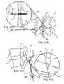
- FIG. 1illustrates a portion of the human spine having a superior vertebra 2 and an inferior vertebra 4 , with an intervertebral disc 6 located in between the two vertebral bodies.
- the superior vertebra 2has superior facet joints 8 a and 8 b , inferior facet joints 10 a and 10 b , and spinous process 18 .
- Pedicles 3 a and 3 binterconnect the respective superior facet joints 8 a , 8 b to the vertebral body 2 .
- Extending laterally from superior facet joints 8 a , 8 bare transverse processes 7 a and 7 b , respectively.
- Extending between each inferior facet joints 10 a and 10 b and the spinous process 18are laminal zones 5 a and 5 b , respectively.
- inferior vertebra 4has superior facet joints 12 a and 12 b , superior pedicles 9 a and 9 b , transverse processes 11 a and 11 b , inferior facet joints 14 a and 14 b , laminal zones 15 a and 15 b , and spinous process 22 .
- the superior vertebra with its inferior facets, the inferior vertebra with its superior facet joints, the intervertebral disc, and seven spinal ligaments (not shown) extending between the superior and inferior vertebrae togethercomprise a spinal motion segment or functional spine unit.
- Each spinal motion segmentenables motion along three orthogonal axes, both in rotation and in translation.
- the various spinal motionsare illustrated in FIGS. 2A-2C .
- FIG. 2Aillustrates flexion and extension motions and axial loading
- FIG. 2Billustrates lateral bending motion
- FIG. 2Cillustrated axial rotational motion.
- a normally functioning spinal motion segmentprovides physiological limits and stiffness in each rotational and translational direction to create a stable and strong column structure to support physiological loads.
- the specific location or source of spinal painis most often an affected intervertebral disc or facet joint. Often, a disorder in one location or spinal component can lead to eventual deterioration or disorder, and ultimately, pain in the other.
- Spine fusionis a procedure in which two or more adjacent vertebral bodies are fused together. It is one of the most common approaches to alleviating various types of spinal pain, particularly pain associated with one or more affected intervertebral discs. While spine fusion generally helps to eliminate certain types of pain, it has been shown to decrease function by limiting the range of motion for patients in flexion, extension, rotation and lateral bending. Furthermore, the fusion creates increased stresses on adjacent non-fused motion segments and accelerated degeneration of the motion segments. Additionally, pseudarthrosis (resulting from an incomplete or ineffective fusion) may not provide the expected pain-relief for the patient. Also, the device(s) used for fusion, whether artificial or biological, may migrate out of the fusion site creating significant new problems for the patient.
- facet jointscan also be a significant source of spinal disorders and debilitating pain.
- a patientmay suffer from arthritic facet joints, severe facet joint tropism, otherwise deformed facet joints, facet joint injuries, etc.
- spinal stenosis, degenerative spondylolithesis, and/or isthmic spondylotlisthesispinching the nerves that extend between the affected vertebrae.
- Facetectomyretractal of the facet joints
- Laminectomyretractal of the lamina, including the spinal arch and the spinous process
- problems with the facet jointscan also complicate treatments associated with other portions of the spine.
- contraindications for disc replacementinclude arthritic facet joints, absent facet joints, severe facet joint tropism, or otherwise deformed facet joints due to the inability of the artificial disc (when used with compromised or missing facet joints) to properly restore the natural biomechanics of the spinal motion segment.
- facet joint replacementWhile various attempts have been made at facet joint replacement, they have been inadequate. This is due to the fact that prosthetic facet joints preserve existing bony structures and therefore do not address pathologies that affect facet joints themselves. Certain facet joint prostheses, such as those disclosed in U.S. Pat. No. 6,132,464, are intended to be supported on the lamina or the posterior arch. As the lamina is a very complex and highly variable anatomical structure, it is very difficult to design a prosthesis that provides reproducible positioning against the lamina to correctly locate the prosthetic facet joints. In addition, when facet joint replacement involves complete removal and replacement of the natural facet joint, as disclosed in U.S. Pat. No.
- the prosthesisis unlikely to endure the loads and cycling experienced by the vertebra.
- the facet joint replacementmay be subject to long-term displacement.
- facet joint disordersare accompanied by disease or trauma to other structures of a vertebra (such as the lamina, spinous process, and/or transverse processes) facet joint replacement is insufficient to treat the problem(s).
- Dynamic posterior stabilizationMost recently, surgical-based technologies, referred to as “dynamic posterior stabilization,” have been developed to address spinal pain resulting from more than one disorder, when more than one structure of the spine have been compromised. An objective of such technologies is to provide the support of fusion-based implants while maximizing the natural biomechanics of the spine. Dynamic posterior stabilization systems typically fall into one of two general categories: posterior pedicle screw-based systems and interspinous spacers.
- pedicle screw-based systemsare disclosed in U.S. Pat. Nos. 5,015,247, 5,484,437, 5,489,308, 5,609,636 and 5,658,337, 5,741,253, 6,080,155, 6,096,038, 6,264,656 and 6,270,498. These types of systems involve the use of screws that are positioned in the vertebral body through the pedicle. Certain types of these pedicle screw-based systems may be used to augment compromised facet joints, while others require removal of the spinous process and/or the facet joints for implantation.
- the Zimmer Spine Dynesys®employs a cord which is extended between the pedicle screws and a fairly rigid spacer which is passed over the cord and positioned between the screws. While this system is able to provide load sharing and restoration of disc height, because it is so rigid, it does not effective in preserving the natural motion of the spinal segment into which it is implanted.
- Other pedicle screw-based systemsemploy articulating joints between the pedicle screws. Because these types of systems require the use of pedicle screws, implantation of the systems are often more invasive to implant than interspinous spacers.
- interspinous spacersare preferred over pedicle based systems as they require a less invasive implantation approach and less dissection of the surrounding tissue and ligaments.
- Examples of interspinous spacersare disclosed in U.S. Pat. Nos. Re. 36,211, 5,645,599, 6,149,642, 6,500,178, 6,695,842, 6,716,245 and 6,761,720.
- the spacerswhich are made of either a hard or compliant material, are placed in between adjacent spinous processes.
- the harder material spacersare fixed in place by means of the opposing force caused by distracting the affected spinal segment and/or by use of keels or screws that anchor into the spinous process. While slightly less invasive than the procedures required for implanting a pedicle screw-based dynamic stabilization system, implantation of hard or solid interspinous spacers still requires dissection of muscle tissue and of the supraspinous and interspinous ligaments. Additionally, these tend to facilitate spinal motion that is less analogous to the natural spinal motion than do the more compliant and flexible interspinous spacers. Another advantage of the compliant/flexible interspinous spacers is the ability to deliver them somewhat less invasively than those that are not compliant or flexible; however, their compliancy makes them more susceptible to displacement or migration over time.
- the present inventionprovides devices, systems and methods for stabilizing at least one spinal motion segment.
- the devicesinclude an expandable spacer or member having an unexpanded configuration and an expanded configuration, wherein the expandable member in an expanded configuration has a size, volume and/or shape configured for positioning between the spinous processes of adjacent vertebrae in order to distract the vertebrae relative to each other.
- the expandable memberis a balloon made of either non-compliant or compliant material which may be porous or non-porous, or may include a mesh material which may be coated or lined with a porous or non-porous material.
- the devicemay further include a port for coupling to a source of an inflation and/or expansion medium for inflating and/or expanding the expandable member.
- the portmay be used to deflate or evacuate the expandable member.
- the devicesmay further include one or more tabs for anchoring the expandable member to the spinous processes.
- the devicemay include one marker on a surface of the expandable member to facilitate fluoroscopic imaging.
- the expandable membersare cages, struts, wires or solid objects having annular, spherical, cylindrical or elliptical shapes when in an expanded condition.
- the expandable membersmay be self-expanding or adjustably expandable depending on the extent of distraction required.
- the inventionfurther includes systems for stabilizing at least one spinal motion segment which include one or more expandable members and an expansion medium for injection within or for filling the interior of the expandable member via the port.
- the subject systemsmay further include at least one means for anchoring or securing the expandable member to the spinal motion segment.
- the inventionfurther includes methods for stabilizing at least one spinal motion segment which involve the implantation of one or more devices or expandable spacers of the present invention, in which the expandable member is positioned between the spinous processes of adjacent vertebrae in an unexpanded or undeployed condition and then subsequently expanded or deployed to a size and/or shape for selectively distracting the adjacent vertebrae.
- the inventionalso contemplates the temporary implantation of the subject devices which may be subsequently removed from the patient once the intended treatment is complete. Many of the methods involve the percutaneous implantation of the subject devices from either an ipsolateral approach or a mid-line approach into the interspinous space.
- FIG. 1illustrated s perspective view of a portion of the human spine having two vertebral segments.
- FIGS. 2A , 2 B and 2 Cillustrate left side, dorsal and top views, respectively, of the spinal segments of FIG. 1A under going various motions.
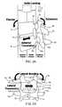
- FIG. 3Aillustrates an interspinous device of the present invention in an unexpanded or collapsed state coupled to a cannula of the delivery system of the present invention.
- FIG. 3Bis an enlarged view of the interspinous device of FIG. 3A .
- FIG. 4Aillustrates an interspinous device of the present invention in an expanded state coupled to a cannula of the delivery system of the present invention.
- FIG. 4Bis an enlarged view of the interspinous device of FIG. 4A .
- FIGS. 5A-5Cillustrates top, dorsal and side views of an initial step of the method of the present invention in which a cannula is delivered to the target implant site.
- FIGS. 6A and 6Billustrate dorsal and side views of the step of dissecting an opening within the spinous ligament utilizing a cutting instrument of the system of FIGS. 3 and 4 .
- FIG. 6Cis an enlarged view of the target area within the spinous ligament.
- FIGS. 7A and 7Billustrate dorsal aid side views of the step of inserting the interspinous device of FIG. 4A into the dissected opening of the spinous ligament.
- FIGS. 7C and 7Dare enlarged views of the target area in FIGS. 7A and 7B , respectively.
- FIGS. 8A and 8Billustrate dorsal aid side views of the step of inflating or expanding the interspinous device of FIG. 4A within the implant site;
- FIGS. 8C and 8Dare enlarged views of the target area in FIGS. 8C and 8D , respectively.
- FIG. 9Aillustrates a side view of the step of filling the interspinous device of FIG. 4A with an expansion medium.
- FIG. 9Bis an enlarged view of the target area in FIG. 9A .
- FIG. 10Aillustrates a dorsal view of the step of further securing the interspinous device of FIG. 4A within the implant site.
- FIG. 10Bis an enlarged view of the target area in FIG. 10A .
- FIGS. 11A and 11Billustrate dorsal aid side views of the step of inserting another embodiment of an interspinous device into the dissected opening of the spinous ligament.
- FIGS. 11C and 11Dare enlarged views of the target area in FIGS. 11A and 11B , respectively.
- FIGS. 12A and 12Billustrate dorsal aid side views of the step of expanding the interspinous device of FIGS. 11A-11D within the implant site.
- FIGS. 12C and 12Dare enlarged views of the target area in FIGS. 12A and 12B , respectively.
- FIG. 13Aillustrates a side view of the step of filling the interspinous device of FIGS. 11A-11D with an expansion medium.
- FIG. 13Bis an enlarged view of the target area in FIG. 13A .
- FIGS. 14A-14Fillustrate dorsal views of another interspinous device of the present invention and a device for implanting the interspinous device where the implantation device is used initially distract the interspinous space prior to implanting the interspinous device.
- FIGS. 15A and 15Billustrate dorsal views of another interspinous device of the present invention implanted within an interspinous space.
- FIGS. 16A and 16Billustrate dorsal views of another interspinous device of the present invention implanted within an interspinous space.
- FIG. 16Cis a side view of FIG. 16B .
- FIGS. 17A and 17Billustrate side views of another interspinous device of the present invention implanted within an interspinous space.
- FIG. 17Cis a dorsal view of FIG. 17B .
- FIGS. 18A and 18Billustrate another interspinous device of the present invention in undeployed and deployed states, respectively.
- FIGS. 19A and 19Billustrate the device of FIG. 18 implanted within an interspinous space and operably coupled to a delivery device of the present invention.
- FIGS. 20A and 20Billustrate cut-away views of two embodiments of the handle portion of the delivery device of FIGS. 19A and 19B .
- FIG. 21illustrates a cut-away view of a distal portion of the device of FIG. 18 operably positioned over the delivery device of FIG. 20B .
- FIGS. 22A-22Cillustrate another interspinous spacer device of the present invention in undeployed, partially deployed and fully deployed states, respectively.
- FIGS. 23A-23Cillustrate another interspinous spacer device of the present invention in undeployed, partially deployed and fully deployed states, respectively.
- FIGS. 24A-24Cillustrate yet another interspinous spacer device of the present invention in undeployed, partially deployed and fully deployed states, respectively.
- FIGS. 25A-25Cillustrate another interspinous spacer device of the present invention in undeployed, partially deployed and fully deployed states, respectively.
- FIGS. 26A and 26Billustrate perspective and front views of another interspinous spacer device of the present invention in a deployed state.
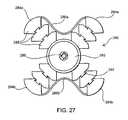
- FIG. 27illustrates a front view of another interspinous spacer device of the present invention.
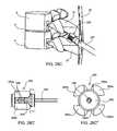
- FIG. 28Aillustrates a step in a method of implanting the interspinous spacer device of FIGS. 26A and 26B .
- FIGS. 28 A′ and 28 A′′illustrate side and front views of the interspinous spacer device in an undeployed state in the context of the step illustrated in FIG. 28A .
- FIG. 28Billustrates a step in a method of implanting the interspinous spacer device of FIGS. 26A and 26B .
- FIGS. 28 B′ and 28 B′′illustrate side and front views of the interspinous spacer device in a partially deployed state in the context of the step illustrated in FIG. 28B .
- FIG. 28Cillustrates a step in a method of implanting the interspinous spacer device of FIGS. 26A and 26B .
- FIGS. 28 C′ and 28 C′′illustrate side and front views of the interspinous spacer device in a partially deployed state in the context of the step illustrated in FIG. 28C .
- FIG. 28Dillustrates a step in a method of implanting the interspinous spacer device of FIGS. 26A and 26B in which the spacer is fully deployed and being released from a delivery device.
- FIG. 28Eillustrates the interspinous spacer device of FIGS. 26A and 26B operatively implanted within an interspinous space.
- FIGS. 29 A and 29 A′illustrate perspective and front views of another interspinous spacer device of the present invention in an undeployed state.
- FIGS. 29 B and 29 B′illustrate perspective and front views of the interspinous spacer device of FIG. 29A in a partially deployed state.
- FIGS. 29 C and 29 C′illustrate perspective and front views of the interspinous spacer device of FIG. 29A in a partially deployed state but one which is more deployed than depicted in FIG. 29B .
- FIGS. 29 D and 29 D′illustrate perspective and front views of the interspinous spacer device of FIG. 29A in a fully deployed state.
- FIGS. 30 A and 30 A′illustrate perspective and front views of another interspinous spacer device of the present invention in a fully deployed state.
- FIGS. 30 B and 30 B′illustrate perspective and side views of the interspinous spacer device of FIG. 30A in an undeployed state.
- FIGS. 30 C and 30 C′illustrate perspective and side views of the interspinous spacer device of FIG. 30A in a partially deployed state.
- the inventiongenerally includes an interspinous spacer device as well as instruments for the percutaneous implantation of the interspinous spacer.
- a key feature of the interspinous spacer deviceis that it is expandable from a low profile configuration to a higher profile or operative configuration. This design allows the device, when in the low profile condition, to be delivered by percutaneous means without requiring the removal of any portion of the spinal motion segment into which the device is implanted.
- Interspinous spacer device 24includes an expandable spacer body 34 that has a size and shape when in the expanded condition for operative positioning between the spinous processes of adjacent superior and inferior vertebrae of the spinal motion segment being treated.
- Expandable body 34is made of an expandable or inflatable biocompatible material such as non-porous material, e.g., latex, acrylate or a metal mesh, e.g., a nitinol or titanium cage.
- balloon type spacersare inflated with an inflation or expansion medium, such as air, saline, another biologically compatible fluid, or a flowable solid material, such as polyurethane, or a gel, which thickens or hardens substantially upon injection into balloon 34 .
- an inflation or expansion mediumsuch as air, saline, another biologically compatible fluid, or a flowable solid material, such as polyurethane, or a gel, which thickens or hardens substantially upon injection into balloon 34 .
- balloon 34is initially inflated with air to provide some structure or rigidity to it to facilitate its optimum positioning and alignment between the spinous processes. Once positioned as desired, balloon 34 is injected with a flowable solid material (the air therein being displaced possibly via a vent hole within port 32 ).
- the expandable bodyis made of a non-compliant or semi-compliant material so as to maintain a substantially fixed shape or configuration and ensure proper, long-term retention within the implant site.
- the expandable membermay be made of a compliant material.
- the compressibility and flexibility of balloon 34can be selected to address the indications being treated.
- FIGS. 11-12Other embodiments of the subject spacers are made of an expandable mesh or cage (see FIGS. 11-12 ).
- the mesh or cagemaybe made of a super-elastic memory material which is compressible for delivery through a cannula and which is self-expanding upon implantation. Upon expansion, the mesh or cage may be self-retaining whereby its struts, links or wires are sufficiently rigid by themselves to maintain the expanded condition and withstand the natural forces exerted on it by spine.
- the mesh or cagemay have an exterior coating or an interior lining made of materials similar to or the same as that used for the balloon spacers, or may otherwise be embedded in such material.
- an expansion mediummay be used to fill the interior of the cage or mesh structure, such as with a biologically compatible fluid or flowable solid material used with the balloon-type embodiments.
- the size or volume of the implanted expandable spacermay be selectively adjusted or varied. For example, after an initial assessment upon implant, it may be necessary to adjust, either reduce or increase, the size or volume of the spacer to optimize the intended treatment. Further, it may be intended to only temporarily implant the spacer for the purpose of treating a temporary condition, e.g., an injured or bulging or herniated disk. Once the repair is achieved or the treatment completed, the spacer may be removed, either with or without substantially reducing the size or volume of the spacer.
- the spacer as well as the inflation/expansion materialmay be made of biodegradable materials wherein the spacer degrades after a time in which the injury is healed or the treatment completed.
- expandable body 34When unexpanded or deflated, as shown in FIGS. 3A and 3B (balloon type) and in FIGS. 11C and 11D (mesh type) expandable body 34 has a low profile, such as a narrow, elongated shape, to be easily translated through a delivery cannula 70 .
- the shape of expandable body 34when in an expanded or inflated state, has larger profile which is generally H-shaped.
- Expandable body 34has lateral or side portions 30 , end portions 26 and apexes 28 defined between the side portions 30 and the end portions 26 .
- End portions 26are preferably recessed or contoured to provide a narrowed central portion along the height dimension or major axis of expandable body 34 to readily fit between and to conform to the spinous processes. Accordingly, expandable body 34 has an apex-to-apex dimension (i.e., height or major axis dimension) from about 3 to about 5 cm and a width dimension (minor axis dimension) from about 2 to about 4 cm
- balloon 34has an inflation or injection port 32 at a sidewall 30 for coupling to a source of inflation or expansion material or medium.
- Port 32may consist of a one-way valve which is self-sealing upon release from an inflation mechanism or tube 76 .
- Port 32is further configured to releasably engage from tube 76 , where such engagement may be threaded or involve a releasable locking mechanism.
- port 32simply acts as an exit port, however, where an expansion material is used, it also functions as an injection port for the expansion material.
- device 24may include a pair of tabs 36 which may be positioned on one side of the device where the tabs 36 are preferably situated at the apexes 28 of expandable body 34 .
- Pins or screwsmay be used to secure the tabs against the spinous process to further ensure long-term retention of device 24 within the implant site.
- Tabs 36are made of a biocompatible material, such as latex, acrylate, rubber, or a metal, and may be made of the same material used for the expandable member 34 .
- Shown here attached to tabs 36are tethers 38 which are used in part to manipulate the positioning of expandable body 34 upon implantation into the targeted spinal motion segment.
- the tethersmay be made of any suitable material including but not limited to materials used to make conventional sutures. They may also be made of a biodegradable material. While two tabs and associated tethers are provided in the illustrated embodiment, one, three or more may be employed, where the respective tabs are located on the expandable body so as to be adjacent a bony structure of the vertebra suitable for anchoring thereto. In embodiments which do not employ securing tabs 36 , tethers 38 may be attached directly to the expandable body itself.
- device 24may further include radiopaque markers 40 on the surface of expandable body 34 visible under fluoroscopic imaging to facilitate positioning of the expandable body. Any number of markers 40 may be employed anywhere on expandable body 34 , however, as few as four markers, one at each apex, may be sufficient. With embodiments employing cage or mesh expandable bodies, the cage or mesh material itself may be radiopaque.
- a system of the present inventionincludes a cannula device 70 having an outer sheath 72 , a proximal hub 78 and preferably at least two interior lumens 74 , 76 for the percutaneous delivery of the device and other tools for implanting the device, which tools may include a cutting instrument 60 (see FIG. 6C ), a device delivery instrument 77 , an endoscope, etc., which tools will be further discussed in the context of the description of the subject methods with reference to FIGS. 5-10 .
- FIGS. 5A-5Cthe spinal motion segment of FIG. 1 is illustrated having spinal ligament 54 extending between the superior spinous process 18 and the inferior spinous process 22 .
- a percutaenous punctureis made into the skin 30 adjacent the target spinal motion segment of a patient undergoing the implantation of the interspinous device of the present invention, and a cannula 70 is penetrated to the spinous ligament 54 .
- the puncture and subsequent penetrationmay be made by way of a sharp distal tip of cannula 70 or by a trocar (not shown) delivered through a lumen of cannula 70 .
- the spinous ligament 54is then dissected and an opening 58 created therein by way of a cutting instrument 60 , such as a simple scalpel, an electrosurgical device or the like, delivered through a lumen of cannula 70 .
- a cutting instrument 60such as a simple scalpel, an electrosurgical device or the like, delivered through a lumen of cannula 70 .
- Cutting instrument 60may then be removed from cannula 70 and, as illustrated in FIGS. 7A-7D (balloon type) and in FIGS. 11A-11D (cage type), a delivery instrument 16 having interspinous device 24 operatively preloaded is delivered through cannula 70 .
- the preloading of device 24 to delivery instrument 76involves providing expandable body 34 in an unexpanded or deflated state and releasably coupled, as described above, by way of inflation or injection port 32 of expandable body 34 to the distal end of delivery instrument 76 .
- instrument 76may act as an inflation lumen for balloon type embodiments through which an inflation medium is transported to within expandable body 34 .
- the expandable bodymay have a degree of stiffness in an unexpanded or deflated state such that it may maintain an elongated configuration so as to be directly insertable and pushable through cannula 70 .
- the expandable member 34is made of a cage or mesh material.
- a pusher or small diameter rod(not shown) may be inserted through inflation port 32 to within expandable body 34 to keep it in an elongated state so as to prevent expandable body 34 from bunching within cannula 70 and to provide some rigidity to more effectively position the expandable body in the target implant site.
- expandable body 34is folded or compressed about its minor axis with the side wall opposite the inflation port 32 defining a distal end 25 (see FIG. 3B ) and the apexes 28 of the expandable body folded proximally of distal end 25 to provide a streamline, low profile configuration for delivery through cannula 70 .
- interspinous device 24is preloaded to delivery device 76 as just described, device 24 is then inserted into a lumen of cannula 70 with tethers 38 pulled back and trail proximally so that the tether ends 38 a extend from hub 78 of cannula 70 .
- Expandable body member 34is translated through cannula 70 to within opening 58 within spinous ligament 54 as best illustrated in FIGS. 7C and 11C .
- expandable body 34is centrally positioned within opening 58 so that the countered ends 26 of expandable body 34 readily engage with the opposed spinous processes 18 , 22 .
- Fluoroscopymay be employed to visualize markers 40 so as to ensure that expandable body 34 centrally straddles the spinous ligament opening 58 , i.e., the markers on the distal side 25 of the expandable body are positioned on one side of the spine and the markers on the proximal side of the expandable body (the side on which port 32 is located) are positioned on the other side of the spine.
- expandable body 34is inflated or expanded, as illustrated in FIGS. 8A-8D and 12 A- 12 D.
- inflationoccurs by allowing an inflation or expansion medium, as discussed above, to enter into the interior of the expandable body via port 32 .
- the expandable bodymay be configured to expand automatically upon exiting cannula 70 .
- the inflation or expansion of expandable body 34may also be visualized under fluoroscopy whereby markers 40 , as best shown in FIG. 8C , are observed and the position of expandable body 34 may be adjusted to ensure optimum positioning upon complete inflation.
- Adjustments of the expandable body's positionmay be accomplished by manually pulling on one or both tether ends 38 a which in turn pulls on tabs 36 to which the tethers 38 are attached at their proximal ends.
- the tethers 38are selectively pulled as necessary to center or optimally position interspinous expandable body 34 to achieve the desired treatment of the targeted spinal motion segment.
- the expandable bodyis initially inflated with air and then filled with a solid or fluid medium
- the latteris preferably not delivered or injected into the interior of the expandable body until the position of the expandable body within the interspinous space has been verified and optimized.
- the expandable bodymay simply be deflated of air to the extent necessary and repositioned in a less inflated or deflated state. If necessary, for example where it is found that the maximum spacer or expandable body size is insufficient for the particular application at hand, expandable body 34 may be completely deflated and removed and replaced with a more suitably sized unit.
- the expansion mediume.g., polyurethane
- expandable body 34is caused to expand to a selected volume and in so doing forces apart (see arrow 80 ) the spinous processes 18 , 22 in between which it is situated.
- This selective distraction of the spinous processesalso results in distraction of the vertebral bodies 2 , 4 (see arrow 82 ) which in turn allows the disk, if bulging or distended, to retract to a more natural position (see arrow 84 ).
- the extent of distraction or lordosis undergone by the subject vertebraecan be monitored by observing expandable body markers 40 under fluoroscopy.
- the extent of possible distractionmaybe limited by the capacity of expandable body 34 and the type of expandable body material employed.
- the requisite volume of the inflation mediummay be substantially fixed whereby the balloon achieves its fully expanded configuration upon filling it with the fixed volume of medium.
- the extent of expansionmay be variable and selectable intraoperatively depending on the extent of lordosis or distraction to be achieved between the spinous processes in which balloon 34 is now interposed.
- inflation/expansion lumen 76is disengaged from expandable body port 32 which then becomes sealed by means of a one-way valve that is closed upon disengagement of lumen 76 . Inflation/expansion lumen is then removed from cannula 70 . While the opposing compressive force exerted on expandable body 34 by the distracted spinous processes 18 , 22 may be sufficient to permanently retain expandable body 34 therebetween, the interspinous device may be further secured to the spinous processes 18 , 22 to ensure that the expandable body does not slip or migrate from its implanted position. To this end, tabs 36 are anchored to the spinous processes as illustrated in FIGS. 10A and 10B and in FIGS. 13A and 13B .
- anchoring meanssuch as screws, tacks, staples, adhesive, etc.
- cannulated screws 90are used as anchors and are delivered to the target site releasably coupled to screw driving instrument 88 .
- screw attachment and release mechanismsmay be employed, a simple configuration involves providing the screws 90 with a threaded inner lumen which is threadably engagable with the threaded distal end of instrument 88 .
- screws 90along with instrument 88 , can be tracked and translated over respective tethers 38 , which function as guide wires.
- instrument 88By manipulating instrument 88 , the screws are driven or screwed into the respective spinous process. Screwdriver 88 is then disengaged or unscrewed from screw 90 . After both tabs 36 are securely anchored to the spinous processes, the screwdriver and the cannula may be removed from the patient's back.
- FIGS. 14A-14Fillustrate an alternative method for implanting the expandable member.
- the methodcontemplates pre-inflating or pre-expanding the expandable member prior to positioning the expandable member within the interspinous space.
- the vertebrae 2 and 4may be distracted prior to insertion of the pre-expandable balloon implant.
- a temporary distraction mechanismsuch as another balloon or a mechanically actuated device, is inserted into the interspinous space.
- the permanent or implantable expandable membercan then be placed within the interspinous space, and the temporary distraction member may then be removed from the space.
- the expansion materialmost likely is a fluid, such as saline, which may be easily aspirated through port 32 or may be allowed to drain out via a penetration or cut made in the expandable member.
- the expansion materialis a flowable solid, which may or may not subsequently harden within the expandable member, the material may be one that is reconstitutable into a liquid form which may then be subsequently aspirated or evacuated from the expandable member.
- a cannulasuch as cannula 70 may be used and an aspiration instrument delivered therethrough and coupled to port 32 .
- the expandable membermay be easily removed through cannula 70 .
- removal of the spaceris obviated.
- any of the above-described steps or proceduresincluding but not limited to cannulation of the target area, dissection of the spinous ligament, insertion of the expandable body within the dissected opening of the spinous ligament, inflation and/or expansion of the expandable body, adjustment or readjustment of the expandable body, and anchoring of the tabs, etc., may be facilitated by way of a scope 62 delivered through a lumen of cannula 70 to the open distal tip of cannula 70 .
- a second cannula delivered through another percutaneous penetrationmay be employed for use of an endoscope and any other instruments needed to facilitate the procedure.
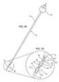
- FIG. 14Aillustrates an exemplary embodiment of a temporary distraction mechanism 100 having an expandable strut configuration.
- Mechanism 100includes bilateral struts 102 which are hinged and foldable at hubs 104 , respectively. Bridging the struts 102 at superior and inferior ends are spinous process engagement portions 106 which are preferably configured to conformingly engage with the spinous processes 18 , 22 . Extending centrally between hubs 104 is a distal portion of guide wire 108 , which also extends proximally through proximal hub 104 a . Guide wire 108 is in threaded engagement with both hub 104 a whereby hub 104 a can be translated both proximally and distally along guide wire 108 .
- expandable member 100can be provided in a low profile, compressed state upon proximally translating hub 104 a in a proximal direction.
- distraction mechanism 100is easily deliverable through cannula 70 , as described above, to with the interspinous space.
- distraction mechanism 100is expandable to a higher profile or expanded state by translating hub 104 a toward hub 104 b in a distal direction along guide wire 108 , as illustrated in FIG. 14A .
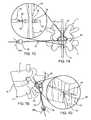
- an implantable expandable member 110 of the present inventionis delivered adjacent the distracted spinal motion segment.
- Expandable member 110may be delivered from the same incision and side as distraction mechanism 100 (ipsolateral approach) and as well as through the same working channel, or may be delivered through a different incision on the same or opposing side of the spinal motion segment being treated (bilateral approach) using two different working channels.
- expandable member 110is delivered from the same side of the spinous process as distraction mechanism 100 .
- Expandable member 110may delivered through a separate designated lumen in cannula 70 and translated distally of hub 104 b of distraction mechanism 100 .
- expandable member 110is inflated or expanded as described above with respect to expandable member 34 , for example, by way of an inflation lumen extending through guide wire 108 .
- Tethers 112may be provided on expandable member 110 to retract and manipulate it to within the interspinous space, as illustrated in FIG. 14C .
- distraction mechanism 100may be removed from the interspinous space immediately or, if the expandable member has been filled with a curable expansion medium or one that involves setting or hardening, the distraction mechanism may be kept in the interspinous space until the desired consistency, curing or hardening has been achieved by the expansion medium.
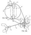
- distraction mechanism 100To remove distraction mechanism 100 from the interspinous space, its profile is reduced to a low profile state, as illustrated in FIG. 14D . As mentioned earlier, this is accomplished by translating proximal hub 104 a proximally along guide wire 108 . Distraction member 100 may be retracted out through a cannula or removed directly in this low profile state, leaving expandable member 100 alone within the implant site as illustrated in FIG. 14E . Tethers 112 may then be cut or secured in place. Optionally, a strap 116 or the like may be implanted to further secure expandable member 110 within the implant site and reduce the risk of migration.
- bores or holes 114have been formed through the thickness of the spinous processes 18 , 22 and strap 116 threaded there through with its ends secured together by a securing means 120 , such as a suture, staple or clip, as illustrated in FIG. 14F .
- a securing means 120such as a suture, staple or clip, as illustrated in FIG. 14F .
- strap 116could be wrapped around the spinous processes 18 , 22 .
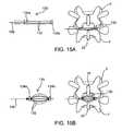
- expandable spacer 130 of FIG. 15Ais a cage-like structure having spaced-apart, parallel strut members 132 extending between and fixed to hubs 134 .
- spacer 130may be provided on and deliverable by way of a guide wire 136 which is threadably engaged to and disengagable from proximal hub 134 a .
- spacer 130is expanded by advancing proximal hub 134 a distally along guide wire 136 thereby forcing struts 132 radially outward and away from each other whereby the expanded configuration of spacer 130 is elliptical or, in a more advanced state of expansion, substantially spherical.
- guide wire 136unthreaded from hub 134 a and removed from the implant region.
- FIGS. 16A and 16Billustrate another embodiment of an expandable spacer 140 which is in the form of a coiled band 142 terminating at an outer end 144 having a configuration for receiving and locking onto inner end 146 upon full expansion or unwinding of the coil.
- the diameter of coil 142 in an unexpanded or fully wound stateis small enough to allow easy insertion between spinous processes 18 , 22 .
- coil 142is allowed to expand and unwind thereby distracting vertebrae 2 and 4 apart from each other.
- inner end 146is coupled to outer end 144 . While the figures show band 142 inserted transversely to spinous processes 18 , 22 , it may alternatively be inserted in line or in the same plan defined by the spinous processes.
- FIGS. 17A-17Cillustrate another interspinous spacer 150 having interlocked nested portions 152 .
- Nested portions 152are each shaped and configured to be received within one of its adjacent portions and to receive the other of the adjacent portions when in a low profile state, as illustrated in FIG. 17A .
- spacer 150which may be spring loaded or be expandable by way of an instrument (not shown) which may be inserted into the spacer's center and rotated to flare portions 152 , vertebrae 2 and 4 are caused to distract from each other.
- Portions 152may have a configuration or shape which allow them to bite or dig into the spinous process 18 , 22 and become securely retained therein.
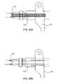
- FIGS. 18A and 18Billustrate another interspinous spacer 160 of the present invention in an undeployed or unexpanded state and a deployed or expanded state, respectively.
- Spacer 160includes an expandable tubular member 162 having end portions 164 a , 164 b which are capped by hubs 166 a , 166 b , respectively.
- hubsmay be provided fixed to tubular member 162 or may be releasably coupled thereto.
- a sleeve or retaining member 168is circumferentially positioned about tubular between end portions 164 a , 165 a .
- interspinous spacer 160may further include a core member (shown in FIG. 21 ) within the lumen of the tubular member and which may be provided integrated with spacer 160 .
- the core membermay be provided as a detachable component of the device used to deliver and implant the spacer (see FIGS. 19A and 19B ).
- spacer 160has an elongated tubular or cylindrical shape, and may have any suitable cross-sectional shape, e.g., circular, oval, starred, etc., where the more angular cross-sections may allow the device to bite or dig into the spinous processes and for better retention.
- tubular member 162has a length in the range from about 20 mm to about 80 mm, and more typically from about 30 mm to about 50 mm, and a diameter or average thickness in the range from about 4 mm to about 12 mm, and more typically from about 6 mm to about 9 mm.
- spacer 160is deliverable to an implant site between adjacent spinous processes in a minimally invasive manner.
- spacer 160In the deployed state, as illustrated in FIG. 18B , spacer 160 has a dumbbell or H-shaped configuration, where the length of spacer 160 is less than and the diameter or height of spacer 160 is greater than the corresponding dimensions of the spacer when in an undeployed state.
- the length dimension of the end portions 164 a , 164 b of tubular member 162has been reduced by about 25% to about 70% while the diameter of the end portions 164 a , 164 b has been increased by about 50% to about 600%, and the diameter of the central or sleeve-covered portion has been increased by about 200% to about 400%, where the diameter of the portions of the tubular member 164 a , 164 b not covered by retaining member 168 have a greater diameter than the portion of tubular member 162 which is covered by retaining member 168 .
- the increased diameter of covered or central portion 168distracts the adjacent vertebrae so as to provide pain relief.
- tubular member 162has a length in the range from about 15 mm to about 50 mm, and more typically from about 20 mm to about 40 mm, and an end portion diameter in the range from about 10 mm to about 60 mm, and more typically from about 15 mm to about 30 mm, and a central portion diameter in the range from about 5 mm to about 30 mm, and more typically from about 8 mm to about 15 mm.
- the deployed spacer 160fits snugly within the interspinous space and is held in place by the surrounding muscle, ligaments and tissue.
- any suitable materialsmay be used to provide a spacer 160 which is provided in a first state or configuration, e.g., the undeployed state illustrated in FIG. 18A , and which can be manipulated to achieve a second state or configuration, and back again if so desired.
- a polymer based material or any other material which allows for simultaneous axial shortening and radial expansionis suitable for use to form tubular member 162 .
- the end portions 164 a , 164 bmay be made of the same or a different material as that of the central or covered portion.
- a flexible or shaped memory material or any other material which also allows for simultaneous axial shortening and radial expansion, but which is less expandable, i.e., maintains a compressive force about tubular member 162 , than the material employed for tubular member 162may be used to form retaining member 168 .
- retaining member 168limits the extent of radial expansion as well as axial shortening that the covered portion of tubular member 162 can undergo.
- suitable materials for the retaining memberinclude but are not limited to Nitinol or polyethelene in a braided or mesh form.
- retaining member 168may be such that the radial force applied to the portion of tubular member 162 that it covers is constant or consistent along its length so as to maintain a constant diameter along its length or, alternatively, may have a varying radial force so as to allow for selective shaping of the covered portion of tubular member when in a deployed state.
- Retaining member 168may be constructed so as to resist bending or flexing upon forcible contact with the spinous processes and, as such, does not conform to the spinous processes.
- the retaining member 168may be constructed from a more flexible material that allows for some compression and, as such, may conform or be conformable to the spinous processes. Further, the physical properties and dimensions of the materials used for both the tubular member and the retaining may be selected to provide the desired amount of distraction between target vertebrae.
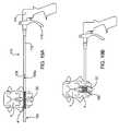
- Delivery device 170includes an outer shaft 172 and an inner shaft 178 , movable relative (axially, rotationally or both) to outer shaft 172 , both extending from a handle mechanism 174 .
- inner shaft 178may be configured to be retracted proximally within outer shaft 172
- outer shaft 172may be configured to be advanced distally over inner shaft 178
- both configurationsmay be employed together, i.e., while outer shaft 178 is advanced, inner shaft 178 is retracted.
- the relative movementmay be accomplished in any suitable manner, for example by way of a screw configuration, i.e., where the shaft members engage by way of corresponding threads, as illustrated in FIG. 20A , or by way of a ratchet configuration, as illustrated in FIG. 20B .
- the relative movementis accomplished by manual actuation of actuator 176 coupled to handle 174 . While only mechanical embodiments of the movement actuation are illustrated, the same can be achieved by electrically or pneumatically-driven devices or mechanisms.
- spacer 160may be provided with an integrated core member or the core member may be detachably provided on the distal end 182 of inner shaft 178 .
- distal end 182 of inner shaft 178is configured to temporarily couple with a proximal end (i.e., the end closest to handle 174 ) of the core member.
- the distal end 182 of inner shaft 178is configured to be inserted into the lumen of tubular member 162 , as illustrated in FIG. 21 , connect to or engaged with distal hub 166 b (i.e., the hub positioned furthest from handle 174 ) and be detachable at a proximal end 184 from inner shaft 178 to function as a core member.
- the end portion 182 of the inner shaft 178 functioning as the core membermay have a length that is as short as the length of tubular member 172 when in a deployed state, with no extra length or remaining portion extending laterally of the implanted device.
- the core lengthmay need to be as long as tubular member 172 when in the undeployed state.
- the core membermay be segmented to allow for selective removal of one or more lengths or portions from the proximal side of the core member subsequent to implantation of the spacer so as not to have any excess length extending from the spacer.
- retraction of inner shaft 178retracts distal hub 166 b towards proximal hub 166 a and/or advancement of outer shaft 172 advances proximal hub 166 a towards distal hub 166 b , thereby causing tubular member 162 to be compressed axially, and thus expanded radially, as shown in FIG. 19B .
- distal hub 166 bmay be fixed to tubular member 162
- proximal hub 166 amay be provided as a separate component having a central bore which allows it to receive and axially translate over inner shaft 178 .
- Proximal hub 166 amay be configured to readily slide over inner shaft 178 in a distal direction (but possibly not in a proximal direction) or may be threaded in order to advance over inner shaft 178 .
- the advancement of proximal hub 166 aaxially compresses tubular member 172 and causes it to radially expand.
- the axial compression or radial expansionmay be continued until the desired extent of distraction occurs between vertebrae 2 and 4 .
- proximal hub 166 ais secured to either the proximal end of tubular member 162 and/or the proximal end of the core member 182 , such as by a threaded or snap-fit engagement or by activating a lock mechanism (not shown).
- Inner shaft 178may then be released from the core member (or distal end 182 of inner shaft 178 may be released from inner shaft 178 and left within tubular member 172 to function as the core member) which, along with the end hubs 166 a and 166 b , maintain the implanted spacer 160 in a deployed state so as to maintain distraction between the vertebrae.
- the reconfiguration of spacer 160may be further facilitated by selectively configuring the wall of tubular member 162 .
- the interior or luminal surface of tubular member 162may be contoured or incorporated with divets or spaces 180 where, upon compression of tubular member 162 , the walls of the uncovered portions 164 a , 164 b of tubular member 162 will more readily fold inward to provide the resulting configuration shown in FIG. 18B .
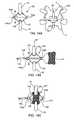
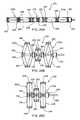
- FIGS. 22A-22Cillustrate another interspinous spacer 190 of the present invention in an undeployed/unexpanded state, in an intermediate state during deployment and in a deployed/expanded state, respectively.
- Spacer 190includes expandable end portions 192 a , 192 b which are capped by hubs 198 a , 198 b , respectively.
- hubsmay be provided fixed to the end members or may be releasably coupled thereto.
- a core member or rod 196extends centrally through end portions 192 a , 192 b and central portion 194 where end blocks 202 are coaxially positioned on core 196 and are slidably translatable thereon.
- Core member 196 or a portion thereofmay be provided integrated with spacer 190 or may be provided as a detachable component of the device used to deliver and implant the spacer.
- end portions 192 a , 192 bmay be made of a polymer based material or any other material which allows for simultaneous axial shortening and radial expansion when compressed.
- Blocks 200 , 202have a more rigid configuration in order to distract the adjacent spinous processes which define the interspinous space into which spacer 190 is positioned without substantial compression of central portion 194 .
- the blocksmay be made of a rigid polymer material, a metal, or the like.
- the blocksare selectively sized, shaped and arranged such that an inwardly compressive force on end blocks 202 along the longitudinal axis of the spacer forces end blocks 202 together which in turn forces side or lateral blocks 200 outward and away from each other, as illustrated in FIG. 22B .
- the inwardly tapered sides of the blocksenable slidable engagement between adjacent blocks.
- the covering (not shown) around the blocksis made of a stretchable material so as to accommodate the radial expansion of central portion 194 .
- the covermay be made of a polymer based material.
- the central and end portions of spacer 190When in an undeployed state, as shown in FIG. 22A , the central and end portions of spacer 190 have tubular or cylindrical configurations, and may have any cross-sectional shape, length and or diameter as provided above with respect to spacer 160 of FIGS. 18A and 18B . Deployment of spacer 190 within an interspinous space may be accomplished in the manner described above. In a fully deployed state, as illustrated in FIG. 22C , spacer 190 has a dumbbell or H-shaped configuration with a change in length and height dimensions as provided above. The increased diameter of central portion 194 when spacer 190 is the deployed configuration distracts the adjacent vertebrae so as to provide pain relief. While the respective dimensions of the spacers change from an undeployed to a deployed state, the spacers may be configured such that the overall size of volume occupied by the spacer does not change.
- Spacer 210includes expandable end portions 212 a , 212 b capped by hubs 224 a , 224 b , respectively.
- hubs 224 a , 224 bmay be provided fixed to the end members or may be releasably coupled thereto.
- Extending between end portions 212 a , 212 bis a central portion 214 including a plurality of linkages 216 and blocks 220 , 222 , which collectively provide opposing struts.
- Each linkage 216has a length and is pivotally coupled to a side block 220 and an end block 222 , where end blocks 222 are coaxially positioned on core 218 and are slidably translatable thereon. While the materials and configuration of end portions 212 a , 212 b may be as described above, linkages 216 are preferably made of a metal material.
- a core member or rod 218extends centrally through end portions 212 a , 212 b and central portion 214 . Core member 218 or a portion thereof may be provided integrated with spacer 210 or may be provided as a detachable component of the device used to deliver and implant the spacer.
- the central and end portions of spacer 190have tubular or cylindrical configurations, and may have any cross-sectional shape, length and or diameter as provided above.
- side blocks 220are close together and end blocks 222 are spaced apart with the lengths of linkages 216 aligned with the longitudinal axis of core member 218 .
- end portions 212 a , 212 baxially compress and radially expand as described above thereby forcing end blocks 222 together which in turn force side or lateral blocks 220 outward and away from each other, as illustrated in FIG. 23B .
- This actioncauses linkages 216 to spread apart, as shown in FIG. 23B , and move to positions where their lengths are transverse to the longitudinal axis of core 218 , as illustrated in FIG. 23C .
- Interspinous spacer 230 of FIGS. 24A-24Cemploys the linkage arrangement of the central portion of spacer 190 of FIGS. 23A-23C in both of its end portions 232 a , 232 b as well as its central portion 234 .
- end portions 232 a , 232 bemploy linkages 236 , which are longer than linkages 238 used for central portion 234 , but which are arranged in similar engagement with side blocks 248 and end blocks 250 .
- dampening washers 244On each side of central portion 234 and in between the central portion and the end portions 232 a , 232 b , respectively, are dampening washers 244 .
- a core member 240extends between and through the end blocks 250 of distal end member 232 a and the end blocks 252 of central portion 234 as well as the dampening washers 244 positioned therebetween, all of which, except the most distal end block, may slidably translatable along core member 240 .
- Core member 240is releasably attached at a proximal end to ratcheted drive rod 242 of a delivery device as discussed above with respect to FIGS. 19-21 which rod 242 extends through the proximal end portion 232 a and hub 246 , as illustrated in FIG. 24B .
- the central and end portions of spacer 230have tubular or cylindrical configurations.
- side blocks 248 and 252 of end portions 232 a , 232 b and central portion 234 , respectively,are close together and end blocks 250 and 252 of end portions 232 a , 232 b and central portion 234 , respectively, are spaced apart with the lengths of linkages 236 , 238 aligned with the longitudinal axis of core member 240 .
- FIGS. 25A-25CSuch a spacer 260 is illustrated in FIGS. 25A-25C .
- Spacer 260includes linkage-block end portions 262 a , 262 b and a compressible central member 264 around which is positioned a circumferential retaining member 278 made of a braided mesh-like material.
- a core member 274extends between and through the end blocks 270 of distal end member 262 a and through central portion 264 , all of which, except the most distal end block, may slidably translatable along core member 260 .
- Core member 260is releasably attached at a proximal end to ratcheted drive rod 272 of a delivery device as discussed above with respect to FIGS. 19-21 which rod 272 extends through the proximal end portion 262 a and hub 272 , as illustrated in FIG. 25B .
- the central and end portions of spacer 230have tubular or cylindrical configurations.
- side blocks 268 of end portions 262 a , 262 bare close together and end blocks 270 of end portions 262 a , 262 b are spaced apart with the lengths of linkages 266 aligned with the longitudinal axis of core member 274 .
- the end blocksare drawn together thereby causing linkages 266 of the end portions to spread apart thereby forcing side or lateral blocks 268 outward and away from each other, as illustrated in FIG. 25B , until linkages 266 move to positions where their lengths are transverse to the longitudinal axis of core 274 , as illustrated in FIG. 25C , the fully deployed state of spacer 260 .
- Each of the expandable and or inflatable interspinous spacers described thus faris particularly configured to be delivered minimally invasively, even percutaneously, from a single incision located laterally to one side (left or right) of the spinal motion segment to be treated.
- the present inventionalso includes interspinous spacers which are deliverable through a mid-line incision made directly into the interspinous ligament. Examples of such spacers are now described.
- FIGS. 26A and 26Bare perspective and front views, respectively, of interspinous spacer 280 which is configured for implantation by way of a percutaneous mid-line approach.
- Spacer 280shown in a deployed state, includes a central member or portion 282 and four struts or legs 284 which are substantially radially expandable from central portion 282 .
- Central portion 282has a cylindrical configuration having a diameter sized for delivery through a small gauge cannula and a length that allows placement within an interspinous space.
- a lumen 285extends at least partially through the center of central portion 282 and is configured, e.g., threaded, to be releasably engaged to a delivery tool.
- Each strut 284includes one or more blocks 288 . Where more than one block 288 per strut is employed, such as with spacer 280 which employs two blocks 288 per strut 284 and spacer 290 of FIG. 27 which employs three blocks 288 per strut 284 , the blocks are stacked and slidably interconnected to each other in a manner that allows the to translate linearly relative to each other along parallel axes.
- a tongue and groove configuration 292is employed with the illustrated embodiment to interconnect stacked blocks, but any suitable interconnection which enables such relative motion between the blocks may be used.
- Such configurationmay also be employed to interconnect the innermost block to central member 282 where outer ridges or tongues 296 on central member 282 slidably interface with a corresponding groove on inner end of the innermost block.
- blocks 288are slidable relative to central member 282 along an axis parallel to the longitudinal axis of central member 282 .
- struts 284may be evenly spaced apart about the circumference of central member 282 . In other embodiments the distance between superior struts 284 a and between inferior struts 284 b may vary and/or the distance between each of those and between struts on the same side of the central member may vary.
- Straps 286may be made of any suitable material which is strong enough to maintain distraction between adjacent spinous processes and to endure any frictional wear which it may undergo due to natural spinal motion.
- the strapsmay be flexible such that they act as slings, or may be conformable to the spinous processes once in situ.
- the strapsmay be non-conforming and rigid with a planar or curved shape depending on the application at hand. Suitable strap materials include but are not limited to polyester, polyethylene, etc.
- FIGS. 28A-28Evarious steps of a method according to the present invention for implanting spacer 280 as well as other spacers of the present invention configured for a mid-line implantation approach into a target spinal motion segment (defined by components of vertebral bodies 2 and 4 ) of a patient are described.
- the initial steps of creating a percutaneous puncture and subsequent penetration into the skin 30 and the dissection of the spinous ligament 54involve many of the same instruments (e.g., K-wire, trocar, cutting instrument, delivery cannula, etc.) and surgical techniques used in the ipsolateral implantation approach described above with respect to FIGS. 5 and 6 .
- a delivery instrument 300 having interspinous device 280 operatively preloaded in an undeployed state at a distal endis delivered to within the interspinous space.
- the delivery instrument 300is provided with a mechanism for releasably connecting to spacer 380 , such as by way of threaded screw 302 (see FIG. 28D ) which is threadedly engaged with threaded lumens 285 of spacer 280 .
- spacer 280when in an undeployed state, spacer 280 has a relatively low profile to facilitate entry into the interspinous space.
- deployment of the spacer 280is initiated, as illustrated in FIG. 28B , by manipulation of instrument 300 which simultaneously causes outward radial movement of the outermost blocks of strut pairs 284 a , 284 b and distal linear advancement of the proximal portion 304 of spacer 282 (see FIGS. 28 B′ and 28 B′′) resulting in radial expansion and axial shortening of spacer 280 .
- Spacer 280may be configured such that deployment of the struts is accomplished by either or both axial rotation of internally componentry or axial compression of central member 282 .
- the delivery instrument 300is released from spacer 280 by unscrewing threaded screw 302 from threaded lumen 285 and removing it from the implant site, as illustrated in FIG. 28D .
- Spacer 280remains behind within the interspinous space, locked in a deployed state (see FIG. 28E ).
- Spacer 280may be configured such that the struts are not retractable without active manipulation of delivery instrument 300 to ensure that their extension, and thus the distraction on the spinal motion segment, is maintained. As configured, spacer 280 may be easily repositioned or removed by subsequent insertion of instrument 300 into the interspinous space and operative engagement with the spacer. Instrument 300 is then manipulated to cause retraction of the struts and the straps, reducing the spacer's profile to allow repositioning or removal of the spacer.
- FIGS. 29A-29Dillustrate another spacer 310 of the present invention that is implantable through a mid-line approach to the interspinous space.
- Spacer 310includes centrally opposed front and rear structures or blocks 312 a , 32 b which are pivotally interconnected on both sides to pairs of elongated linkages 314 .
- the other end of each linkage 314is pivotally connected to a lateral structure 318 a or 318 b .
- the resulting configurationprovides interconnected strut pairs on each side of spacer 310 which move and function similarly to the linkages described above with respect to the spacers illustrated in FIGS.
- the lengths of linkages 314extend parallel to the central axis of spacer 310 when in a fully undeployed state ( FIG. 29A ) and extend transverse to the central axis of spacer 310 in a fully deployed state ( FIG. 29D ).
- Extending between opposing superior lateral structures 318 a and between opposing inferior structures 318 bare straps 316 a and 316 b , respectively.
- Spacer 310is implantable and deployable by way of a mid-line approach similar to that described above with respect to the spacer of FIGS. 28A-28E .
- Spacer 310is preloaded to a delivery instrument shaft 320 which is insertable and axial translatable through a central opening within front block 312 a .
- the distal end of shaft 320is releasably attached to an axial member (not shown) of spacer 310 .
- Axial memberis fixed to rear block 312 b and extends along the central axis of spacer 310 , having a length which extends to front block 312 a when spacer 210 is in a fully deployed state, as illustrated in FIG. 29D but which extends only a portion of the length of spacer 310 when it is in an undeployed state ( FIG. 29A ) or a partially undeployed ( FIGS. 29B and 29C ) state.
- spacer 310which is releasably connected to delivery shaft 320 as described above, is inserted into the space in a fully undeployed sate (see FIGS. 29 A and 29 A′). Deployment of the spacer is accomplished by proximally pulling on shaft 320 which compresses rear block 312 b towards front block 312 a . This in turn causes the linkages 314 to pivot about their respective attachment points with superior and inferior lateral structures or blocks 318 a and 318 b forced away from each other, as illustrated in FIGS. 29 B and 29 B′.
- FIGS. 30A-30Cillustrate yet another spacer 330 of the present invention that is implantable through a mid-line approach to the interspinous space.
- spacer 330includes an elongated central member 332 extending between front and rear hubs 334 a and 334 b and a plurality of flexible or deformable struts 336 which also extend between hubs 334 a , 334 b .
- Struts 336are configured to be deformable and to have a directional character to facilitate deployment of them radially outward from central member 332 .
- Suitable constructs of these strutsinclude but are not limited to thin metal plates, e.g., flat springs, wire bundles or a polymer material. Extending between and affixed to each of strut pairs 336 a and 336 b are straps 338 a and 338 b , respectively.
- the proximal end 342 of central member 332is provided with ratcheted grooves which are releasably engaged within the distal end of 352 of delivery instrument 350 (see FIG. 30 C′).
- Front hub 334 ais provided with an opening 340 which also has a grooved internal surface for engaging with the grooves of central member 332 .
- Spacer 330is implantable and deployable by way of a mid-line approach similar to that described above with respect to the spacer of FIGS. 29A-2D .
- Spacer 330is preloaded in a fully undeployed state to delivery instrument shaft 350 as illustrated in FIGS. 30 B and 30 B′.
- spacer 330is inserted into the interspinous space. Deployment of the spacer is accomplished by proximally pulling on shaft 350 , by ratcheting as described above, which compresses rear hub 334 b towards front hub 334 a or distally pushing on front hub 334 a towards rear hub 334 b .
- struts 336 a , 336 bto flex or bend outward, as illustrated in FIGS. 30 C and 30 C′.
- instrument 350or pushing of hub 334 a
- the strutssuch that they define an X-shaped structure with straps 338 a and 338 b forcably abutting against the interspinous processes.
- the pulling (or pushing) actionadvances the grooved proximal end 342 of central member 332 into grooved opening 340 of front hub 334 a .
- the opposing grooves of the central member and the openingprovide a ratchet relationship between the two whereby central member is readily translatable in a proximal direction but not in a distal direction, thereby locking spacer 330 in a deployed state.
- delivery instrument 350is released from spacer 310 (such as by unscrewing) and removed from the implant site.
- kitswhich include at least one interspinous device of the present invention.
- a plurality of such devicesmay be provided where the devices have the same or varying sizes and shapes and are made of the same or varying materials.
- the kitsmay further include instruments and tools for implanting the subject devices, including but not limited to, a cannula, a trocar, a scope, a device delivery/inflation/expansion lumen, a cutting instrument, a screw driver, etc., as well as a selection of screws or other devices for anchoring the spacer tabs to the spinous processes.
- the kitsmay also include a supply of the expandable body inflation and/or expansion medium. Instructions for implanting the interspinous spacers and using the above-described instrumentation may also be provided with the kits.
Landscapes
- Health & Medical Sciences (AREA)
- Orthopedic Medicine & Surgery (AREA)
- Life Sciences & Earth Sciences (AREA)
- Neurology (AREA)
- Surgery (AREA)
- Heart & Thoracic Surgery (AREA)
- Engineering & Computer Science (AREA)
- Biomedical Technology (AREA)
- Nuclear Medicine, Radiotherapy & Molecular Imaging (AREA)
- Medical Informatics (AREA)
- Molecular Biology (AREA)
- Animal Behavior & Ethology (AREA)
- General Health & Medical Sciences (AREA)
- Public Health (AREA)
- Veterinary Medicine (AREA)
- Prostheses (AREA)
- Surgical Instruments (AREA)
Abstract
Description
This application is a continuation-in-part of U.S. patent application Ser. No. 11/052,002, filed on Feb. 4, 2005, which is a continuation-in-part of U.S. patent application Ser. No. 11/006,502, filed on Dec. 6, 2004, which is a continuation-in-part of U.S. patent application Ser. No. 10/970,843, filed on Oct. 20, 2004, incorporated herein by reference in their entireties.
The present invention is directed towards the treatment of spinal disorders and pain. More particularly, the present invention is directed to systems and methods of treating the spine, which eliminate pain and enable spinal motion, which effectively mimics that of a normally functioning spine.
The superior vertebra with its inferior facets, the inferior vertebra with its superior facet joints, the intervertebral disc, and seven spinal ligaments (not shown) extending between the superior and inferior vertebrae together comprise a spinal motion segment or functional spine unit. Each spinal motion segment enables motion along three orthogonal axes, both in rotation and in translation. The various spinal motions are illustrated inFIGS. 2A-2C . In particular,FIG. 2A illustrates flexion and extension motions and axial loading,FIG. 2B illustrates lateral bending motion andFIG. 2C illustrated axial rotational motion. A normally functioning spinal motion segment provides physiological limits and stiffness in each rotational and translational direction to create a stable and strong column structure to support physiological loads.
Traumatic, inflammatory, metabolic, synovial, neoplastic and degenerative disorders of the spine can produce debilitating pain that can affect a spinal motion segment's ability to properly function. The specific location or source of spinal pain is most often an affected intervertebral disc or facet joint. Often, a disorder in one location or spinal component can lead to eventual deterioration or disorder, and ultimately, pain in the other.
Spine fusion (arthrodesis) is a procedure in which two or more adjacent vertebral bodies are fused together. It is one of the most common approaches to alleviating various types of spinal pain, particularly pain associated with one or more affected intervertebral discs. While spine fusion generally helps to eliminate certain types of pain, it has been shown to decrease function by limiting the range of motion for patients in flexion, extension, rotation and lateral bending. Furthermore, the fusion creates increased stresses on adjacent non-fused motion segments and accelerated degeneration of the motion segments. Additionally, pseudarthrosis (resulting from an incomplete or ineffective fusion) may not provide the expected pain-relief for the patient. Also, the device(s) used for fusion, whether artificial or biological, may migrate out of the fusion site creating significant new problems for the patient.
Various technologies and approaches have been developed to treat spinal pain without fusion in order to maintain or recreate the natural biomechanics of the spine. To this end, significant efforts are being made in the use of implantable artificial intervertebral discs. Artificial discs are intended to restore articulation between vertebral bodies so as to recreate the full range of motion normally allowed by the elastic properties of the natural disc. Unfortunately, the currently available artificial discs do not adequately address all of the mechanics of motion for the spinal column.
It has been found that the facet joints can also be a significant source of spinal disorders and debilitating pain. For example, a patient may suffer from arthritic facet joints, severe facet joint tropism, otherwise deformed facet joints, facet joint injuries, etc. These disorders lead to spinal stenosis, degenerative spondylolithesis, and/or isthmic spondylotlisthesis, pinching the nerves that extend between the affected vertebrae.
Current interventions for the treatment of facet joint disorders have not been found to provide completely successful results. Facetectomy (removal of the facet joints) may provide some pain relief; but as the facet joints help to support axial, torsional, and shear loads that act on the spinal column in addition to providing a sliding articulation and mechanism for load transmission, their removal inhibits natural spinal function. Laminectomy (removal of the lamina, including the spinal arch and the spinous process) may also provide pain relief associated with facet joint disorders; however, the spine is made less stable and subject to hypermobility. Problems with the facet joints can also complicate treatments associated with other portions of the spine. In fact, contraindications for disc replacement include arthritic facet joints, absent facet joints, severe facet joint tropism, or otherwise deformed facet joints due to the inability of the artificial disc (when used with compromised or missing facet joints) to properly restore the natural biomechanics of the spinal motion segment.
While various attempts have been made at facet joint replacement, they have been inadequate. This is due to the fact that prosthetic facet joints preserve existing bony structures and therefore do not address pathologies that affect facet joints themselves. Certain facet joint prostheses, such as those disclosed in U.S. Pat. No. 6,132,464, are intended to be supported on the lamina or the posterior arch. As the lamina is a very complex and highly variable anatomical structure, it is very difficult to design a prosthesis that provides reproducible positioning against the lamina to correctly locate the prosthetic facet joints. In addition, when facet joint replacement involves complete removal and replacement of the natural facet joint, as disclosed in U.S. Pat. No. 6,579,319, the prosthesis is unlikely to endure the loads and cycling experienced by the vertebra. Thus, the facet joint replacement may be subject to long-term displacement. Furthermore, when facet joint disorders are accompanied by disease or trauma to other structures of a vertebra (such as the lamina, spinous process, and/or transverse processes) facet joint replacement is insufficient to treat the problem(s).
Most recently, surgical-based technologies, referred to as “dynamic posterior stabilization,” have been developed to address spinal pain resulting from more than one disorder, when more than one structure of the spine have been compromised. An objective of such technologies is to provide the support of fusion-based implants while maximizing the natural biomechanics of the spine. Dynamic posterior stabilization systems typically fall into one of two general categories: posterior pedicle screw-based systems and interspinous spacers.
Examples of pedicle screw-based systems are disclosed in U.S. Pat. Nos. 5,015,247, 5,484,437, 5,489,308, 5,609,636 and 5,658,337, 5,741,253, 6,080,155, 6,096,038, 6,264,656 and 6,270,498. These types of systems involve the use of screws that are positioned in the vertebral body through the pedicle. Certain types of these pedicle screw-based systems may be used to augment compromised facet joints, while others require removal of the spinous process and/or the facet joints for implantation. One such system, the Zimmer Spine Dynesys® employs a cord which is extended between the pedicle screws and a fairly rigid spacer which is passed over the cord and positioned between the screws. While this system is able to provide load sharing and restoration of disc height, because it is so rigid, it does not effective in preserving the natural motion of the spinal segment into which it is implanted. Other pedicle screw-based systems employ articulating joints between the pedicle screws. Because these types of systems require the use of pedicle screws, implantation of the systems are often more invasive to implant than interspinous spacers.
Where the level of disability or pain to the affected spinal motion segments is not that severe or where the condition, such as an injury, is not chronic, the use of interspinous spacers are preferred over pedicle based systems as they require a less invasive implantation approach and less dissection of the surrounding tissue and ligaments. Examples of interspinous spacers are disclosed in U.S. Pat. Nos. Re. 36,211, 5,645,599, 6,149,642, 6,500,178, 6,695,842, 6,716,245 and 6,761,720. The spacers, which are made of either a hard or compliant material, are placed in between adjacent spinous processes. The harder material spacers are fixed in place by means of the opposing force caused by distracting the affected spinal segment and/or by use of keels or screws that anchor into the spinous process. While slightly less invasive than the procedures required for implanting a pedicle screw-based dynamic stabilization system, implantation of hard or solid interspinous spacers still requires dissection of muscle tissue and of the supraspinous and interspinous ligaments. Additionally, these tend to facilitate spinal motion that is less analogous to the natural spinal motion than do the more compliant and flexible interspinous spacers. Another advantage of the compliant/flexible interspinous spacers is the ability to deliver them somewhat less invasively than those that are not compliant or flexible; however, their compliancy makes them more susceptible to displacement or migration over time. To obviate this risk, many of these spacers employ straps or the like that are wrapped around the spinous processes of the vertebrae above and below the level where the spacer is implanted. Of course, this requires some additional tissue and ligament dissection superior and inferior to the implant site, i.e., at least within the adjacent interspinous spaces.
With the limitations of current spine stabilization technologies, there is clearly a need for an improved means and method for dynamic posterior stabilization of the spine that address the drawbacks of prior devices. In particular, it would be highly beneficial to have a dynamic stabilization system that involves a minimally invasive implantation procedure, where the extent of distraction between the affected vertebrae is adjustable upon implantation and at a later time if necessary. It would be additionally advantageous if the system or device was also removable in a minimally invasive manner.
The present invention provides devices, systems and methods for stabilizing at least one spinal motion segment. The devices include an expandable spacer or member having an unexpanded configuration and an expanded configuration, wherein the expandable member in an expanded configuration has a size, volume and/or shape configured for positioning between the spinous processes of adjacent vertebrae in order to distract the vertebrae relative to each other.
In certain embodiments, the expandable member is a balloon made of either non-compliant or compliant material which may be porous or non-porous, or may include a mesh material which may be coated or lined with a porous or non-porous material. The device may further include a port for coupling to a source of an inflation and/or expansion medium for inflating and/or expanding the expandable member. In certain embodiments, the port may be used to deflate or evacuate the expandable member. The devices may further include one or more tabs for anchoring the expandable member to the spinous processes. Optionally, the device may include one marker on a surface of the expandable member to facilitate fluoroscopic imaging.
In other embodiments, the expandable members are cages, struts, wires or solid objects having annular, spherical, cylindrical or elliptical shapes when in an expanded condition. The expandable members may be self-expanding or adjustably expandable depending on the extent of distraction required.
The invention further includes systems for stabilizing at least one spinal motion segment which include one or more expandable members and an expansion medium for injection within or for filling the interior of the expandable member via the port. The subject systems may further include at least one means for anchoring or securing the expandable member to the spinal motion segment.
The invention further includes methods for stabilizing at least one spinal motion segment which involve the implantation of one or more devices or expandable spacers of the present invention, in which the expandable member is positioned between the spinous processes of adjacent vertebrae in an unexpanded or undeployed condition and then subsequently expanded or deployed to a size and/or shape for selectively distracting the adjacent vertebrae. The invention also contemplates the temporary implantation of the subject devices which may be subsequently removed from the patient once the intended treatment is complete. Many of the methods involve the percutaneous implantation of the subject devices from either an ipsolateral approach or a mid-line approach into the interspinous space.
These and other objects, advantages, and features of the invention will become apparent to those persons skilled in the art upon reading the details of the invention as more fully described below.
The invention is best understood from the following detailed description when read in conjunction with the accompanying drawings. It is emphasized that, according to common practice, the various features of the drawings are not to-scale. On the contrary, the dimensions of the various features are arbitrarily expanded or reduced for clarity. Included in the drawings are the following figures:
FIGS.29A and29A′ illustrate perspective and front views of another interspinous spacer device of the present invention in an undeployed state.
FIGS.29B and29B′ illustrate perspective and front views of the interspinous spacer device ofFIG. 29A in a partially deployed state.
FIGS.29C and29C′ illustrate perspective and front views of the interspinous spacer device ofFIG. 29A in a partially deployed state but one which is more deployed than depicted inFIG. 29B .
FIGS.29D and29D′ illustrate perspective and front views of the interspinous spacer device ofFIG. 29A in a fully deployed state.
FIGS.30A and30A′ illustrate perspective and front views of another interspinous spacer device of the present invention in a fully deployed state.
FIGS.30B and30B′ illustrate perspective and side views of the interspinous spacer device ofFIG. 30A in an undeployed state.
FIGS.30C and30C′ illustrate perspective and side views of the interspinous spacer device ofFIG. 30A in a partially deployed state.
Before the subject devices, systems and methods are described, it is to be understood that this invention is not limited to particular embodiments described, as such may, of course, vary. It is also to be understood that the terminology used herein is for the purpose of describing particular embodiments only, and is not intended to be limiting, since the scope of the present invention will be limited only by the appended claims.
Unless defined otherwise, all technical and scientific terms used herein have the same meaning as commonly understood by one of ordinary skill in the art to which this invention belongs.
It must be noted that as used herein and in the appended claims, the singular forms “a”, “an”, and “the” include plural referents unless the context clearly dictates otherwise. Thus, for example, reference to “a spinal segment” may include a plurality of such spinal segments and reference to “the screw” includes reference to one or more screw and equivalents thereof known to those skilled in the art, and so forth.
Where a range of values is provided, it is understood that each intervening value, to the tenth of the unit of the lower limit unless the context clearly dictates otherwise, between the upper and lower limits of that range is also specifically disclosed. Each smaller range between any stated value or intervening value in a stated range and any other stated or intervening value in that stated range is encompassed within the invention. The upper and lower limits of these smaller ranges may independently be included or excluded in the range, and each range where either, neither or both limits are included in the smaller ranges is also encompassed within the invention, subject to any specifically excluded limit in the stated range. Where the stated range includes one or both of the limits, ranges excluding either or both of those included limits are also included in the invention.
All publications mentioned herein are incorporated herein by reference to disclose and describe the methods and/or materials in connection with which the publications are cited. The publications discussed herein are provided solely for their disclosure prior to the filing date of the present application. Nothing herein is to be construed as an admission that the present invention is not entitled to antedate such publication by virtue of prior invention. Further, the dates of publication provided may be different from the actual publication dates which may need to be independently confirmed.
The present invention will now be described in greater detail by way of the following description of exemplary embodiments and variations of the devices and methods of the present invention. The invention generally includes an interspinous spacer device as well as instruments for the percutaneous implantation of the interspinous spacer. A key feature of the interspinous spacer device is that it is expandable from a low profile configuration to a higher profile or operative configuration. This design allows the device, when in the low profile condition, to be delivered by percutaneous means without requiring the removal of any portion of the spinal motion segment into which the device is implanted.
Referring now to the drawings and toFIGS. 3 and 4 in particular, an exemplaryinterspinous spacer device 24 of the present invention is illustrated in collapsed and expanded configurations, respectively.Interspinous device 24 includes anexpandable spacer body 34 that has a size and shape when in the expanded condition for operative positioning between the spinous processes of adjacent superior and inferior vertebrae of the spinal motion segment being treated.Expandable body 34 is made of an expandable or inflatable biocompatible material such as non-porous material, e.g., latex, acrylate or a metal mesh, e.g., a nitinol or titanium cage.
Those spacers made of an inflatable non-porous material, i.e., balloon type spacers (seeFIGS. 3-10 ), are inflated with an inflation or expansion medium, such as air, saline, another biologically compatible fluid, or a flowable solid material, such as polyurethane, or a gel, which thickens or hardens substantially upon injection intoballoon 34. In one embodiment,balloon 34 is initially inflated with air to provide some structure or rigidity to it to facilitate its optimum positioning and alignment between the spinous processes. Once positioned as desired,balloon 34 is injected with a flowable solid material (the air therein being displaced possibly via a vent hole within port32). In certain embodiments, the expandable body is made of a non-compliant or semi-compliant material so as to maintain a substantially fixed shape or configuration and ensure proper, long-term retention within the implant site. In other embodiments, the expandable member may be made of a compliant material. In any embodiment, the compressibility and flexibility ofballoon 34 can be selected to address the indications being treated.
Other embodiments of the subject spacers are made of an expandable mesh or cage (seeFIGS. 11-12 ). The mesh or cage maybe made of a super-elastic memory material which is compressible for delivery through a cannula and which is self-expanding upon implantation. Upon expansion, the mesh or cage may be self-retaining whereby its struts, links or wires are sufficiently rigid by themselves to maintain the expanded condition and withstand the natural forces exerted on it by spine. The mesh or cage may have an exterior coating or an interior lining made of materials similar to or the same as that used for the balloon spacers, or may otherwise be embedded in such material. In certain embodiments, an expansion medium may be used to fill the interior of the cage or mesh structure, such as with a biologically compatible fluid or flowable solid material used with the balloon-type embodiments.
In certain embodiments of present invention, either during the implant procedure or in a subsequent procedure, the size or volume of the implanted expandable spacer may be selectively adjusted or varied. For example, after an initial assessment upon implant, it may be necessary to adjust, either reduce or increase, the size or volume of the spacer to optimize the intended treatment. Further, it may be intended to only temporarily implant the spacer for the purpose of treating a temporary condition, e.g., an injured or bulging or herniated disk. Once the repair is achieved or the treatment completed, the spacer may be removed, either with or without substantially reducing the size or volume of the spacer. In other embodiments, the spacer as well as the inflation/expansion material may be made of biodegradable materials wherein the spacer degrades after a time in which the injury is healed or the treatment completed.
When unexpanded or deflated, as shown inFIGS. 3A and 3B (balloon type) and inFIGS. 11C and 11D (mesh type)expandable body 34 has a low profile, such as a narrow, elongated shape, to be easily translated through adelivery cannula 70. The shape ofexpandable body 34, when in an expanded or inflated state, has larger profile which is generally H-shaped.Expandable body 34 has lateral orside portions 30,end portions 26 and apexes28 defined between theside portions 30 and theend portions 26.End portions 26 are preferably recessed or contoured to provide a narrowed central portion along the height dimension or major axis ofexpandable body 34 to readily fit between and to conform to the spinous processes. Accordingly,expandable body 34 has an apex-to-apex dimension (i.e., height or major axis dimension) from about 3 to about 5 cm and a width dimension (minor axis dimension) from about 2 to about 4 cm
For those embodiments of expandable bodies which comprise a balloon configuration,balloon 34 has an inflation orinjection port 32 at asidewall 30 for coupling to a source of inflation or expansion material or medium.Port 32 may consist of a one-way valve which is self-sealing upon release from an inflation mechanism ortube 76.Port 32 is further configured to releasably engage fromtube 76, where such engagement may be threaded or involve a releasable locking mechanism. Where the expandable body comprises a mesh or cage,port 32 simply acts as an exit port, however, where an expansion material is used, it also functions as an injection port for the expansion material.
Optionally,device 24 may include a pair oftabs 36 which may be positioned on one side of the device where thetabs 36 are preferably situated at theapexes 28 ofexpandable body 34. Pins or screws (not yet shown) may be used to secure the tabs against the spinous process to further ensure long-term retention ofdevice 24 within the implant site.Tabs 36 are made of a biocompatible material, such as latex, acrylate, rubber, or a metal, and may be made of the same material used for theexpandable member 34. Shown here attached totabs 36 aretethers 38 which are used in part to manipulate the positioning ofexpandable body 34 upon implantation into the targeted spinal motion segment. The tethers may be made of any suitable material including but not limited to materials used to make conventional sutures. They may also be made of a biodegradable material. While two tabs and associated tethers are provided in the illustrated embodiment, one, three or more may be employed, where the respective tabs are located on the expandable body so as to be adjacent a bony structure of the vertebra suitable for anchoring thereto. In embodiments which do not employ securingtabs 36, tethers38 may be attached directly to the expandable body itself.
Optionally still,device 24 may further includeradiopaque markers 40 on the surface ofexpandable body 34 visible under fluoroscopic imaging to facilitate positioning of the expandable body. Any number ofmarkers 40 may be employed anywhere onexpandable body 34, however, as few as four markers, one at each apex, may be sufficient. With embodiments employing cage or mesh expandable bodies, the cage or mesh material itself may be radiopaque.
A system of the present invention includes acannula device 70 having anouter sheath 72, aproximal hub 78 and preferably at least twointerior lumens FIG. 6C ), a device delivery instrument77, an endoscope, etc., which tools will be further discussed in the context of the description of the subject methods with reference toFIGS. 5-10 .
InFIGS. 5A-5C , the spinal motion segment ofFIG. 1 is illustrated havingspinal ligament 54 extending between the superiorspinous process 18 and the inferiorspinous process 22. A percutaenous puncture is made into theskin 30 adjacent the target spinal motion segment of a patient undergoing the implantation of the interspinous device of the present invention, and acannula 70 is penetrated to thespinous ligament 54. The puncture and subsequent penetration may be made by way of a sharp distal tip ofcannula 70 or by a trocar (not shown) delivered through a lumen ofcannula 70.
As illustrated inFIGS. 6A-6C , thespinous ligament 54 is then dissected and anopening 58 created therein by way of a cuttinginstrument 60, such as a simple scalpel, an electrosurgical device or the like, delivered through a lumen ofcannula 70. Cuttinginstrument 60 may then be removed fromcannula 70 and, as illustrated inFIGS. 7A-7D (balloon type) and inFIGS. 11A-11D (cage type), adelivery instrument 16 havinginterspinous device 24 operatively preloaded is delivered throughcannula 70.
The preloading ofdevice 24 todelivery instrument 76 involves providingexpandable body 34 in an unexpanded or deflated state and releasably coupled, as described above, by way of inflation orinjection port 32 ofexpandable body 34 to the distal end ofdelivery instrument 76. In addition to functioning as a pusher,instrument 76 may act as an inflation lumen for balloon type embodiments through which an inflation medium is transported to withinexpandable body 34.
Depending upon the material used to fabricateexpandable body 34, the expandable body may have a degree of stiffness in an unexpanded or deflated state such that it may maintain an elongated configuration so as to be directly insertable and pushable throughcannula 70. This may be the case where theexpandable member 34 is made of a cage or mesh material. Alternatively, a pusher or small diameter rod (not shown) may be inserted throughinflation port 32 to withinexpandable body 34 to keep it in an elongated state so as to preventexpandable body 34 from bunching withincannula 70 and to provide some rigidity to more effectively position the expandable body in the target implant site. The rod is then removed fromexpandable body 34 and fromdelivery device 76 upon positioning the expandable body at the target implant site. In either case,expandable body 34 is folded or compressed about its minor axis with the side wall opposite theinflation port 32 defining a distal end25 (seeFIG. 3B ) and theapexes 28 of the expandable body folded proximally ofdistal end 25 to provide a streamline, low profile configuration for delivery throughcannula 70.
Onceinterspinous device 24 is preloaded todelivery device 76 as just described,device 24 is then inserted into a lumen ofcannula 70 withtethers 38 pulled back and trail proximally so that the tether ends38aextend fromhub 78 ofcannula 70.Expandable body member 34 is translated throughcannula 70 to within opening58 withinspinous ligament 54 as best illustrated inFIGS. 7C and 11C . For best results,expandable body 34 is centrally positioned within opening58 so that the countered ends26 ofexpandable body 34 readily engage with the opposed spinous processes18,22. Fluoroscopy may be employed to visualizemarkers 40 so as to ensure thatexpandable body 34 centrally straddles thespinous ligament opening 58, i.e., the markers on thedistal side 25 of the expandable body are positioned on one side of the spine and the markers on the proximal side of the expandable body (the side on whichport 32 is located) are positioned on the other side of the spine.
Once centrally positioned,expandable body 34 is inflated or expanded, as illustrated inFIGS. 8A-8D and12A-12D. For balloon spacers, inflation occurs by allowing an inflation or expansion medium, as discussed above, to enter into the interior of the expandable body viaport 32. For expandable mesh spacers, the expandable body may be configured to expand automatically upon exitingcannula 70. The inflation or expansion ofexpandable body 34 may also be visualized under fluoroscopy wherebymarkers 40, as best shown inFIG. 8C , are observed and the position ofexpandable body 34 may be adjusted to ensure optimum positioning upon complete inflation. Adjustments of the expandable body's position may be accomplished by manually pulling on one or both tether ends38awhich in turn pulls ontabs 36 to which thetethers 38 are attached at their proximal ends. Thetethers 38 are selectively pulled as necessary to center or optimally position interspinousexpandable body 34 to achieve the desired treatment of the targeted spinal motion segment.
With embodiments in which the expandable body is initially inflated with air and then filled with a solid or fluid medium, the latter is preferably not delivered or injected into the interior of the expandable body until the position of the expandable body within the interspinous space has been verified and optimized. This is beneficial in situations where, upon inflation, it is found that the expandable body is misaligned within the interspinous space and requires repositioning. The expandable body may simply be deflated of air to the extent necessary and repositioned in a less inflated or deflated state. If necessary, for example where it is found that the maximum spacer or expandable body size is insufficient for the particular application at hand,expandable body 34 may be completely deflated and removed and replaced with a more suitably sized unit.
For balloon spacers and those mesh spacers which are not by themselves sufficiently self-retaining, once the position and extent of inflation or expansion ofexpandable body 34 are optimized, the expansion medium, e.g., polyurethane, is allowed to flow or injected into the interior of the expandable body viaport 32. As illustrated inFIGS. 9A and 9B ,expandable body 34 is caused to expand to a selected volume and in so doing forces apart (see arrow80) the spinous processes18,22 in between which it is situated. This selective distraction of the spinous processes also results in distraction of thevertebral bodies 2,4 (see arrow82) which in turn allows the disk, if bulging or distended, to retract to a more natural position (see arrow84). Again, the extent of distraction or lordosis undergone by the subject vertebrae can be monitored by observingexpandable body markers 40 under fluoroscopy.
The extent of possible distraction maybe limited by the capacity ofexpandable body 34 and the type of expandable body material employed. In certain embodiments, such as expandable bodies made of non-compliant or semi-compliant balloons, the requisite volume of the inflation medium may be substantially fixed whereby the balloon achieves its fully expanded configuration upon filling it with the fixed volume of medium. In other embodiments, such as with balloons made of a compliant material, the extent of expansion may be variable and selectable intraoperatively depending on the extent of lordosis or distraction to be achieved between the spinous processes in whichballoon 34 is now interposed.
Upon achieving the desired distraction between the vertebrae, inflation/expansion lumen 76 is disengaged fromexpandable body port 32 which then becomes sealed by means of a one-way valve that is closed upon disengagement oflumen 76. Inflation/expansion lumen is then removed fromcannula 70. While the opposing compressive force exerted onexpandable body 34 by the distractedspinous processes expandable body 34 therebetween, the interspinous device may be further secured to the spinous processes18,22 to ensure that the expandable body does not slip or migrate from its implanted position. To this end,tabs 36 are anchored to the spinous processes as illustrated inFIGS. 10A and 10B and inFIGS. 13A and 13B . Any type of anchoring means, such as screws, tacks, staples, adhesive, etc. may be employed to anchortabs 36. Here, cannulated screws90 are used as anchors and are delivered to the target site releasably coupled to screw drivinginstrument 88. While various screw attachment and release mechanisms may be employed, a simple configuration involves providing thescrews 90 with a threaded inner lumen which is threadably engagable with the threaded distal end ofinstrument 88.
To ensure accurate placement ofscrews 90, along withinstrument 88, can be tracked and translated overrespective tethers 38, which function as guide wires. By manipulatinginstrument 88, the screws are driven or screwed into the respective spinous process.Screwdriver 88 is then disengaged or unscrewed fromscrew 90. After bothtabs 36 are securely anchored to the spinous processes, the screwdriver and the cannula may be removed from the patient's back.
While certain of the expandable spacers are intended to be permanently implanted within a spine, certain others may be implanted only temporarily to facilitate the healing of an injury or the treatment of a reversible or non-chronic condition, such as a herniated disk. For such temporary treatments, the expansion material most likely is a fluid, such as saline, which may be easily aspirated throughport 32 or may be allowed to drain out via a penetration or cut made in the expandable member. In those embodiments in which the expansion material is a flowable solid, which may or may not subsequently harden within the expandable member, the material may be one that is reconstitutable into a liquid form which may then be subsequently aspirated or evacuated from the expandable member. For percutaneous removal of the expandable member, a cannula such ascannula 70 may be used and an aspiration instrument delivered therethrough and coupled toport 32. After deflation and/or evacuation of the expandable member, and removal of the tacks, sutures, staples, etc. if such are used to securetabs 36, the expandable member may be easily removed throughcannula 70. With biodegradable spacers, removal of the spacer is obviated.
It should be noted that any of the above-described steps or procedures, including but not limited to cannulation of the target area, dissection of the spinous ligament, insertion of the expandable body within the dissected opening of the spinous ligament, inflation and/or expansion of the expandable body, adjustment or readjustment of the expandable body, and anchoring of the tabs, etc., may be facilitated by way of ascope 62 delivered through a lumen ofcannula 70 to the open distal tip ofcannula 70. Alternatively, a second cannula delivered through another percutaneous penetration may be employed for use of an endoscope and any other instruments needed to facilitate the procedure.
After the desired amount of distraction is achieved betweenvertebrae expandable member 110 of the present invention is delivered adjacent the distracted spinal motion segment.Expandable member 110 may be delivered from the same incision and side as distraction mechanism100 (ipsolateral approach) and as well as through the same working channel, or may be delivered through a different incision on the same or opposing side of the spinal motion segment being treated (bilateral approach) using two different working channels. In the illustrated embodiment,expandable member 110 is delivered from the same side of the spinous process asdistraction mechanism 100.Expandable member 110 may delivered through a separate designated lumen incannula 70 and translated distally ofhub 104bofdistraction mechanism 100.
As shown inFIG. 14B , after deployment,expandable member 110 is inflated or expanded as described above with respect toexpandable member 34, for example, by way of an inflation lumen extending throughguide wire 108.Tethers 112 may be provided onexpandable member 110 to retract and manipulate it to within the interspinous space, as illustrated inFIG. 14C . Onceexpandable member 110 is properly positioned within the interspinous space,distraction mechanism 100 may be removed from the interspinous space immediately or, if the expandable member has been filled with a curable expansion medium or one that involves setting or hardening, the distraction mechanism may be kept in the interspinous space until the desired consistency, curing or hardening has been achieved by the expansion medium. To removedistraction mechanism 100 from the interspinous space, its profile is reduced to a low profile state, as illustrated inFIG. 14D . As mentioned earlier, this is accomplished by translatingproximal hub 104aproximally alongguide wire 108.Distraction member 100 may be retracted out through a cannula or removed directly in this low profile state, leavingexpandable member 100 alone within the implant site as illustrated inFIG. 14E .Tethers 112 may then be cut or secured in place. Optionally, astrap 116 or the like may be implanted to further secureexpandable member 110 within the implant site and reduce the risk of migration. Here, bores orholes 114 have been formed through the thickness of the spinous processes18,22 andstrap 116 threaded there through with its ends secured together by a securing means120, such as a suture, staple or clip, as illustrated inFIG. 14F . Alternatively,strap 116 could be wrapped around the spinous processes18,22.
In addition to the expandable balloon spacers, the present invention further provides for mechanically expandable spacers such as those illustrated inFIGS. 15-17 . For example,expandable spacer 130 ofFIG. 15A is a cage-like structure having spaced-apart,parallel strut members 132 extending between and fixed to hubs134. Like the distraction mechanism ofFIGS. 14A-14F ,spacer 130 may be provided on and deliverable by way of aguide wire 136 which is threadably engaged to and disengagable fromproximal hub 134a. After placement ofspacer 130 within the interspinous space, as illustrated inFIG. 15A ,spacer 130 is expanded by advancingproximal hub 134adistally alongguide wire 136 thereby forcingstruts 132 radially outward and away from each other whereby the expanded configuration ofspacer 130 is elliptical or, in a more advanced state of expansion, substantially spherical. Once the desired degree of distraction is achieved betweenvertebrae guide wire 136 unthreaded fromhub 134aand removed from the implant region.
In the undeployed state, as illustrated inFIG. 18A ,spacer 160 has an elongated tubular or cylindrical shape, and may have any suitable cross-sectional shape, e.g., circular, oval, starred, etc., where the more angular cross-sections may allow the device to bite or dig into the spinous processes and for better retention. In this undeployed or lengthened state,tubular member 162 has a length in the range from about 20 mm to about 80 mm, and more typically from about 30 mm to about 50 mm, and a diameter or average thickness in the range from about 4 mm to about 12 mm, and more typically from about 6 mm to about 9 mm. As such,spacer 160 is deliverable to an implant site between adjacent spinous processes in a minimally invasive manner.
In the deployed state, as illustrated inFIG. 18B ,spacer 160 has a dumbbell or H-shaped configuration, where the length ofspacer 160 is less than and the diameter or height ofspacer 160 is greater than the corresponding dimensions of the spacer when in an undeployed state. In particular, the length dimension of theend portions tubular member 162 has been reduced by about 25% to about 70% while the diameter of theend portions tubular member member 168 have a greater diameter than the portion oftubular member 162 which is covered by retainingmember 168. The increased diameter of covered orcentral portion 168 distracts the adjacent vertebrae so as to provide pain relief. The diameter ofhubs device 160. In this deployed state,tubular member 162 has a length in the range from about 15 mm to about 50 mm, and more typically from about 20 mm to about 40 mm, and an end portion diameter in the range from about 10 mm to about 60 mm, and more typically from about 15 mm to about 30 mm, and a central portion diameter in the range from about 5 mm to about 30 mm, and more typically from about 8 mm to about 15 mm. As such, when operatively placed and deployed within an interspinous space, the deployedspacer 160 fits snugly within the interspinous space and is held in place by the surrounding muscle, ligaments and tissue.
Any suitable materials may be used to provide aspacer 160 which is provided in a first state or configuration, e.g., the undeployed state illustrated inFIG. 18A , and which can be manipulated to achieve a second state or configuration, and back again if so desired. A polymer based material or any other material which allows for simultaneous axial shortening and radial expansion is suitable for use to formtubular member 162. Theend portions tubular member 162, than the material employed fortubular member 162 may be used to form retainingmember 168. As such, retainingmember 168 limits the extent of radial expansion as well as axial shortening that the covered portion oftubular member 162 can undergo. Examples of suitable materials for the retaining member include but are not limited to Nitinol or polyethelene in a braided or mesh form. Further, the construct of retainingmember 168 may be such that the radial force applied to the portion oftubular member 162 that it covers is constant or consistent along its length so as to maintain a constant diameter along its length or, alternatively, may have a varying radial force so as to allow for selective shaping of the covered portion of tubular member when in a deployed state. Retainingmember 168 may be constructed so as to resist bending or flexing upon forcible contact with the spinous processes and, as such, does not conform to the spinous processes. Conversely, the retainingmember 168 may be constructed from a more flexible material that allows for some compression and, as such, may conform or be conformable to the spinous processes. Further, the physical properties and dimensions of the materials used for both the tubular member and the retaining may be selected to provide the desired amount of distraction between target vertebrae.
Referring now toFIGS. 19A and 19B ,spacer 160 is shown operatively employed within an interspinous space and coupled todelivery device 170.Delivery device 170 includes anouter shaft 172 and aninner shaft 178, movable relative (axially, rotationally or both) toouter shaft 172, both extending from ahandle mechanism 174. For example,inner shaft 178 may be configured to be retracted proximally withinouter shaft 172, orouter shaft 172 may be configured to be advanced distally overinner shaft 178, or both configurations may be employed together, i.e., whileouter shaft 178 is advanced,inner shaft 178 is retracted. The relative movement may be accomplished in any suitable manner, for example by way of a screw configuration, i.e., where the shaft members engage by way of corresponding threads, as illustrated inFIG. 20A , or by way of a ratchet configuration, as illustrated inFIG. 20B . The relative movement is accomplished by manual actuation ofactuator 176 coupled to handle174. While only mechanical embodiments of the movement actuation are illustrated, the same can be achieved by electrically or pneumatically-driven devices or mechanisms.
As mentioned above,spacer 160 may be provided with an integrated core member or the core member may be detachably provided on thedistal end 182 ofinner shaft 178. In the first embodiment,distal end 182 ofinner shaft 178 is configured to temporarily couple with a proximal end (i.e., the end closest to handle174) of the core member. In the latter embodiment, thedistal end 182 ofinner shaft 178 is configured to be inserted into the lumen oftubular member 162, as illustrated inFIG. 21 , connect to or engaged withdistal hub 166b(i.e., the hub positioned furthest from handle174) and be detachable at aproximal end 184 frominner shaft 178 to function as a core member. An advantage of the latter embodiment is that theend portion 182 of theinner shaft 178 functioning as the core member may have a length that is as short as the length oftubular member 172 when in a deployed state, with no extra length or remaining portion extending laterally of the implanted device. In the integrated embodiment, the core length may need to be as long astubular member 172 when in the undeployed state. However, the core member may be segmented to allow for selective removal of one or more lengths or portions from the proximal side of the core member subsequent to implantation of the spacer so as not to have any excess length extending from the spacer.
With either embodiment, retraction ofinner shaft 178, as described above, retractsdistal hub 166btowardsproximal hub 166aand/or advancement ofouter shaft 172 advancesproximal hub 166atowardsdistal hub 166b, thereby causingtubular member 162 to be compressed axially, and thus expanded radially, as shown inFIG. 19B . Whiledistal hub 166bmay be fixed totubular member 162,proximal hub 166amay be provided as a separate component having a central bore which allows it to receive and axially translate overinner shaft 178.Proximal hub 166amay be configured to readily slide overinner shaft 178 in a distal direction (but possibly not in a proximal direction) or may be threaded in order to advance overinner shaft 178. The advancement ofproximal hub 166aaxially compressestubular member 172 and causes it to radially expand. The axial compression or radial expansion may be continued until the desired extent of distraction occurs betweenvertebrae proximal hub 166ais secured to either the proximal end oftubular member 162 and/or the proximal end of thecore member 182, such as by a threaded or snap-fit engagement or by activating a lock mechanism (not shown).Inner shaft 178 may then be released from the core member (ordistal end 182 ofinner shaft 178 may be released frominner shaft 178 and left withintubular member 172 to function as the core member) which, along with theend hubs spacer 160 in a deployed state so as to maintain distraction between the vertebrae.
The reconfiguration ofspacer 160 may be further facilitated by selectively configuring the wall oftubular member 162. For example, the interior or luminal surface oftubular member 162 may be contoured or incorporated with divets orspaces 180 where, upon compression oftubular member 162, the walls of the uncoveredportions tubular member 162 will more readily fold inward to provide the resulting configuration shown inFIG. 18B .
As with the previously described spacer,end portions Blocks central portion 194. As such, the blocks may be made of a rigid polymer material, a metal, or the like. In order to effect radial expansion and axial shortening ofcentral portion 194, the blocks are selectively sized, shaped and arranged such that an inwardly compressive force onend blocks 202 along the longitudinal axis of the spacer forces endblocks 202 together which in turn forces side orlateral blocks 200 outward and away from each other, as illustrated inFIG. 22B . The inwardly tapered sides of the blocks enable slidable engagement between adjacent blocks. The covering (not shown) around the blocks is made of a stretchable material so as to accommodate the radial expansion ofcentral portion 194. As such, the cover may be made of a polymer based material.
When in an undeployed state, as shown inFIG. 22A , the central and end portions ofspacer 190 have tubular or cylindrical configurations, and may have any cross-sectional shape, length and or diameter as provided above with respect tospacer 160 ofFIGS. 18A and 18B . Deployment ofspacer 190 within an interspinous space may be accomplished in the manner described above. In a fully deployed state, as illustrated inFIG. 22C ,spacer 190 has a dumbbell or H-shaped configuration with a change in length and height dimensions as provided above. The increased diameter ofcentral portion 194 whenspacer 190 is the deployed configuration distracts the adjacent vertebrae so as to provide pain relief. While the respective dimensions of the spacers change from an undeployed to a deployed state, the spacers may be configured such that the overall size of volume occupied by the spacer does not change.
Anotherinterspinous spacer 210 of the present invention is illustrated in an undeployed/unexpanded state, in an intermediate state during deployment and in a deployed/expanded state inFIGS. 23A-23C , respectively.Spacer 210 includesexpandable end portions end portions central portion 214 including a plurality oflinkages 216 and blocks220,222, which collectively provide opposing struts. Eachlinkage 216 has a length and is pivotally coupled to aside block 220 and anend block 222, where end blocks222 are coaxially positioned oncore 218 and are slidably translatable thereon. While the materials and configuration ofend portions linkages 216 are preferably made of a metal material. A core member orrod 218 extends centrally throughend portions central portion 214.Core member 218 or a portion thereof may be provided integrated withspacer 210 or may be provided as a detachable component of the device used to deliver and implant the spacer.
In an undeployed state, as shown inFIG. 23A , the central and end portions ofspacer 190 have tubular or cylindrical configurations, and may have any cross-sectional shape, length and or diameter as provided above. As such, side blocks220 are close together and endblocks 222 are spaced apart with the lengths oflinkages 216 aligned with the longitudinal axis ofcore member 218. When opposing, inwardly compressive forces are exerted onspacer 210 along its longitudinal axis,end portions lateral blocks 220 outward and away from each other, as illustrated inFIG. 23B . This action causeslinkages 216 to spread apart, as shown inFIG. 23B , and move to positions where their lengths are transverse to the longitudinal axis ofcore 218, as illustrated inFIG. 23C .
In an undeployed state, as shown inFIG. 24A , the central and end portions ofspacer 230 have tubular or cylindrical configurations. As such, side blocks248 and252 ofend portions central portion 234, respectively, are close together and endblocks end portions central portion 234, respectively, are spaced apart with the lengths oflinkages core member 240. When opposing, inwardly compressive forces are exerted on thedistal block 250 andhub 246 ofspacer 230 along its longitudinal axis, the end blocks are drawn together thereby forcing side orlateral blocks 220 outward and away from each other, as illustrated inFIG. 24B . This action causes the linkages of the end and central portions to spread apart, and move to positions where their lengths are transverse to the longitudinal axis ofcore 240, as illustrated inFIG. 24C , the fully deployed state ofspacer 230.
The end portions and central portions of the compressible spacers described above may be used in any combination. For example, the polymer-based central portion ofFIGS. 18A and 18B and the linkage end portions ofFIGS. 24A-24C may be used together to form a spacer of the present invention. Such aspacer 260 is illustrated inFIGS. 25A-25C .Spacer 260 includes linkage-block end portions central member 264 around which is positioned a circumferential retainingmember 278 made of a braided mesh-like material. Acore member 274 extends between and through the end blocks270 ofdistal end member 262aand throughcentral portion 264, all of which, except the most distal end block, may slidably translatable alongcore member 260.Core member 260 is releasably attached at a proximal end to ratcheteddrive rod 272 of a delivery device as discussed above with respect toFIGS. 19-21 whichrod 272 extends through theproximal end portion 262aandhub 272, as illustrated inFIG. 25B .
In an undeployed state, as shown inFIG. 25A , the central and end portions ofspacer 230 have tubular or cylindrical configurations. As such, side blocks268 ofend portions blocks 270 ofend portions linkages 266 aligned with the longitudinal axis ofcore member 274. When opposing, inwardly compressive forces are exerted on thedistal block 270 andhub 272 ofspacer 260 along its longitudinal axis, the end blocks are drawn together thereby causinglinkages 266 of the end portions to spread apart thereby forcing side orlateral blocks 268 outward and away from each other, as illustrated inFIG. 25B , untillinkages 266 move to positions where their lengths are transverse to the longitudinal axis ofcore 274, as illustrated inFIG. 25C , the fully deployed state ofspacer 260.
Each of the expandable and or inflatable interspinous spacers described thus far is particularly configured to be delivered minimally invasively, even percutaneously, from a single incision located laterally to one side (left or right) of the spinal motion segment to be treated. However, the present invention also includes interspinous spacers which are deliverable through a mid-line incision made directly into the interspinous ligament. Examples of such spacers are now described.
Each strut284 includes one ormore blocks 288. Where more than oneblock 288 per strut is employed, such as withspacer 280 which employs twoblocks 288 per strut284 andspacer 290 ofFIG. 27 which employs threeblocks 288 per strut284, the blocks are stacked and slidably interconnected to each other in a manner that allows the to translate linearly relative to each other along parallel axes. A tongue andgroove configuration 292 is employed with the illustrated embodiment to interconnect stacked blocks, but any suitable interconnection which enables such relative motion between the blocks may be used. Such configuration may also be employed to interconnect the innermost block tocentral member 282 where outer ridges ortongues 296 oncentral member 282 slidably interface with a corresponding groove on inner end of the innermost block. As such, blocks288 are slidable relative tocentral member 282 along an axis parallel to the longitudinal axis ofcentral member 282. Depending on the application and the particular anatomy of the implant site, struts284 may be evenly spaced apart about the circumference ofcentral member 282. In other embodiments the distance betweensuperior struts 284aand betweeninferior struts 284bmay vary and/or the distance between each of those and between struts on the same side of the central member may vary.
Spanning between eachstrut pair strap
With reference toFIGS. 28A-28E , various steps of a method according to the present invention for implantingspacer 280 as well as other spacers of the present invention configured for a mid-line implantation approach into a target spinal motion segment (defined by components ofvertebral bodies 2 and4) of a patient are described.
The initial steps of creating a percutaneous puncture and subsequent penetration into theskin 30 and the dissection of thespinous ligament 54 involve many of the same instruments (e.g., K-wire, trocar, cutting instrument, delivery cannula, etc.) and surgical techniques used in the ipsolateral implantation approach described above with respect toFIGS. 5 and 6 . Upon creating an opening within the interspinous space extending between the superiorspinous process 18 and the inferiorspinous process 22, adelivery instrument 300 havinginterspinous device 280 operatively preloaded in an undeployed state at a distal end is delivered to within the interspinous space. Thedelivery instrument 300 is provided with a mechanism for releasably connecting to spacer380, such as by way of threaded screw302 (seeFIG. 28D ) which is threadedly engaged with threadedlumens 285 ofspacer 280.
As best illustrated in FIGS.28A′ and28A″, when in an undeployed state,spacer 280 has a relatively low profile to facilitate entry into the interspinous space. Once properly positioned within the interspinous space, deployment of thespacer 280 is initiated, as illustrated inFIG. 28B , by manipulation ofinstrument 300 which simultaneously causes outward radial movement of the outermost blocks of strut pairs284a,284band distal linear advancement of theproximal portion 304 of spacer282 (see FIGS.28B′ and28B″) resulting in radial expansion and axial shortening ofspacer 280.Spacer 280 may be configured such that deployment of the struts is accomplished by either or both axial rotation of internally componentry or axial compression ofcentral member 282.
As the struts are radially extended, straps286aand286bemerge and they become tauter as the slack in them is gradually reduced by the extension of the struts. Continued deployment ofspacer 280 causesstraps spinous processes FIGS. 28C ,28C′ and28C″, until the desired amount of distraction between the vertebra is achieved. This selective distraction of the spinous processes also results in distraction of thevertebral bodies
At this point, thedelivery instrument 300 is released fromspacer 280 by unscrewing threadedscrew 302 from threadedlumen 285 and removing it from the implant site, as illustrated inFIG. 28D .Spacer 280 remains behind within the interspinous space, locked in a deployed state (seeFIG. 28E ).
After the necessary space is created within the interspinous space as described above,spacer 310, which is releasably connected todelivery shaft 320 as described above, is inserted into the space in a fully undeployed sate (see FIGS.29A and29A′). Deployment of the spacer is accomplished by proximally pulling onshaft 320 which compressesrear block 312btowardsfront block 312a. This in turn causes thelinkages 314 to pivot about their respective attachment points with superior and inferior lateral structures orblocks instrument 320 further expandslinkages 314 in a direction transverse to the central axis ofspacer 310 and extendstraps rear blocks front block 312aand locked to it. Additionally, straps316aand316bare firmly engaged against the spinous processes and the contacted vertebra are distracted from each other.Delivery instrument 320 may then be released fromspacer 310 and removed from the implant site.
Theproximal end 342 ofcentral member 332 is provided with ratcheted grooves which are releasably engaged within the distal end of352 of delivery instrument350 (see FIG.30C′).Front hub 334ais provided with anopening 340 which also has a grooved internal surface for engaging with the grooves ofcentral member 332.
The subject devices and systems may be provided in the form of a kit which includes at least one interspinous device of the present invention. A plurality of such devices may be provided where the devices have the same or varying sizes and shapes and are made of the same or varying materials. The kits may further include instruments and tools for implanting the subject devices, including but not limited to, a cannula, a trocar, a scope, a device delivery/inflation/expansion lumen, a cutting instrument, a screw driver, etc., as well as a selection of screws or other devices for anchoring the spacer tabs to the spinous processes. The kits may also include a supply of the expandable body inflation and/or expansion medium. Instructions for implanting the interspinous spacers and using the above-described instrumentation may also be provided with the kits.
The preceding merely illustrates the principles of the invention. It will be appreciated that those skilled in the art will be able to devise various arrangements which, although not explicitly described or shown herein, embody the principles of the invention and are included within its spirit and scope. Furthermore, all examples and conditional language recited herein are principally intended to aid the reader in understanding the principles of the invention and the concepts contributed by the inventors to furthering the art, and are to be construed as being without limitation to such specifically recited examples and conditions. Moreover, all statements herein reciting principles, aspects, and embodiments of the invention as well as specific examples thereof, are intended to encompass both structural and functional equivalents thereof. Additionally, it is intended that such equivalents include both currently known equivalents and equivalents developed in the future, i.e., any elements developed that perform the same function, regardless of structure. The scope of the present invention, therefore, is not intended to be limited to the exemplary embodiments shown and described herein. Rather, the scope and spirit of present invention is embodied by the appended claims.
Claims (22)
1. A method for stabilizing a superior vertebra having a superior spinous process relative to an inferior vertebra having an inferior spinous process, wherein the superior and inferior spinous processes define an interspinous space, the method comprising:
inserting an interspinous device into the interspinous space by moving the interspinous device anteriorly substantially along a midline relative to the superior and inferior spinous processes through an incision located posterior of the interspinous space;
moving a superior strut unit of the interspinous device by radial expansion to extend superiorly such that the superior spinous process is seated between first and second superior struts of the superior strut unit, wherein the superior strut unit is moved after implanting the interspinous device; and
moving an inferior strut unit of the interspinous device by radial expansion to extend inferiorly such that the inferior spinous process is seated between first and second inferior struts of the inferior strut unit, wherein the inferior strut unit is moved after implanting the interspinous device.
2. The method ofclaim 1 , wherein the interspinous device has an anterior-posterior axis and the superior and inferior struts extend along the anterior-posterior axis while inserting the interspinous device into the interspinous space.
3. The method ofclaim 2 wherein moving the superior and inferior strut units comprises extending the first and second superior struts and the first and second inferior struts away from the anterior-posterior axis.
4. The method ofclaim 3 wherein the interspinous device has a tool interface facing posteriorly and the method comprises engaging a delivery tool with the tool interface before inserting the interspinous device into the interspinous space, and wherein extending the first and second superior struts and the first and second inferior struts comprises manipulating the delivery tool while the delivery tool extends posteriorly relative to the first and second vertebrae through the incision posterior of the interspinous space.
5. The method ofclaim 4 wherein the first and second superior struts and the first and second inferior struts are extended simultaneously.
6. The method ofclaim 2 wherein the first and second superior struts and the first and second inferior struts are rotated away from the anterior-posterior axis simultaneously.
7. The method ofclaim 4 wherein, while the delivery tool extends through the incision, the delivery tool has a shaft extending substantially perpendicular to a plane that is substantially perpendicular to the anterior-posterior axis.
8. The method ofclaim 1 wherein moving the first strut unit and moving the second strut unit comprises rotating the first and second strut units such that the first and second superior struts and the first and second inferior struts are in a transverse plane at least substantially perpendicular to the anterior-posterior axis after extension.
9. The method ofclaim 8 wherein the superior strut unit and the inferior strut unit together define an X-shaped configuration in the transverse plane after deployment.
10. The method ofclaim 8 wherein the superior strut unit and the inferior strut unit together define an H-shaped configuration in the transverse plane after deployment.
11. The method ofclaim 1 , further comprising forming the incision at the midline posterior of the interspinous space and inserting the device comprises passing the device through the midline incision.
12. A method for stabilizing a superior vertebra having a superior spinous process relative to an inferior vertebra having an inferior spinous process, comprising:
creating an incision at a midline located posterior of the interspinous space;
inserting an interspinous device into the interspinous space by moving the interspinous device anteriorly relative to the incision; and
changing the interspinous device from an undeployed configuration to a deployed configuration by radial expansion, wherein the interspinous device includes a pair of inferior struts and a pair of superior struts which are configured to have a low profile in the undeployed configuration relative to the deployed configuration, and wherein the inferior struts of the interspinous device are configured to seat the inferior spinous processes in the deployed configuration and the superior struts of the interspinous device are configured to seat the superior spinous processes in the deployed configuration, and thereby relieve pain.
13. The method ofclaim 12 , wherein the interspinous device has an anterior-posterior axis and the superior and inferior struts extend along the anterior-posterior axis while inserting the interspinous device into the interspinous space.
14. The method ofclaim 13 wherein the interspinous device has a tool interface facing posteriorly and the method comprises engaging a delivery tool with the tool interface before inserting the interspinous device into the interspinous space, and wherein extending the first and second superior struts and the first and second inferior struts comprises manipulating the delivery tool while the delivery tool extends posteriorly relative to the first and second vertebrae through the incision posterior of the interspinous space.
15. The method ofclaim 12 wherein moving the superior and inferior strut pairs comprises extending the first and second superior struts and the first and second inferior struts away from the anterior-posterior axis.
16. The method ofclaim 15 wherein the first and second superior struts and the first and second inferior struts are extended simultaneously.
17. The method ofclaim 15 wherein, while the delivery tool extends through the incision, the delivery tool has a shaft extending substantially perpendicular to a plane that is substantially perpendicular to the anterior-posterior axis.
18. The method ofclaim 12 wherein the first and second superior struts and the first and second inferior struts are rotated away from the anterior-posterior axis simultaneously.
19. The method ofclaim 12 wherein moving the inferior strut pair and moving the superior strut pair comprises rotating the inferior and superior strut pair such that the first and second superior struts and the first and second inferior struts are in a transverse plane at least substantially perpendicular to the anterior-posterior axis after extension.
20. The method ofclaim 19 wherein the superior strut pair and the inferior strut pair together define an X-shaped configuration in the transverse plane after deployment.
21. The method ofclaim 19 wherein the superior strut unit and the inferior strut unit together define an H-shaped configuration in the transverse plane after deployment.
22. The method ofclaim 12 , further comprising forming the incision at the midline posterior of the interspinous space and inserting the device comprises passing the device through the midline incision.
Priority Applications (49)
| Application Number | Priority Date | Filing Date | Title |
|---|---|---|---|
| US11/079,006US8012207B2 (en) | 2004-10-20 | 2005-03-10 | Systems and methods for posterior dynamic stabilization of the spine |
| US11/190,496US8409282B2 (en) | 2004-10-20 | 2005-07-26 | Systems and methods for posterior dynamic stabilization of the spine |
| AU2005295212AAU2005295212B2 (en) | 2004-10-20 | 2005-10-20 | Systems and methods for posterior dynamic stabilization of the spine |
| EP20050815519EP1802242A4 (en) | 2004-10-20 | 2005-10-20 | SYSTEM AND METHOD FOR POSTERIOR DYNAMIC STABILIZATION OF THE VERTEBRAL COLUMN |
| CA2582127ACA2582127C (en) | 2004-10-20 | 2005-10-20 | Systems and methods for posterior dynamic stabilization of the spine |
| PCT/US2005/038026WO2006045094A2 (en) | 2004-10-20 | 2005-10-20 | Systems and methods for posterior dynamic stabilization of the spine |
| US11/305,820US7763074B2 (en) | 2004-10-20 | 2005-12-15 | Systems and methods for posterior dynamic stabilization of the spine |
| US11/314,712US8152837B2 (en) | 2004-10-20 | 2005-12-20 | Systems and methods for posterior dynamic stabilization of the spine |
| US11/582,874US8128662B2 (en) | 2004-10-20 | 2006-10-18 | Minimally invasive tooling for delivery of interspinous spacer |
| US11/593,995US8425559B2 (en) | 2004-10-20 | 2006-11-07 | Systems and methods for posterior dynamic stabilization of the spine |
| US12/148,104US8292922B2 (en) | 2004-10-20 | 2008-04-16 | Interspinous spacer |
| US12/217,662US8273108B2 (en) | 2004-10-20 | 2008-07-08 | Interspinous spacer |
| PCT/US2008/008983WO2009014728A2 (en) | 2004-10-20 | 2008-07-24 | Interspinous spacer |
| US12/220,427US8277488B2 (en) | 2004-10-20 | 2008-07-24 | Interspinous spacer |
| US12/205,511US8123782B2 (en) | 2004-10-20 | 2008-09-05 | Interspinous spacer |
| PCT/US2008/087527WO2009086010A2 (en) | 2004-12-06 | 2008-12-18 | Spacer insertion instrument |
| AU2008343092AAU2008343092B2 (en) | 2004-12-06 | 2008-12-18 | Spacer insertion instrument |
| US12/338,793US8613747B2 (en) | 2004-10-20 | 2008-12-18 | Spacer insertion instrument |
| EP08867282.9AEP2219538B1 (en) | 2004-12-06 | 2008-12-18 | Spacer insertion instrument |
| CA2701050ACA2701050A1 (en) | 2004-12-06 | 2008-12-18 | Spacer insertion instrument |
| US12/354,517US8864828B2 (en) | 2004-10-20 | 2009-01-15 | Interspinous spacer |
| US12/400,601US8945183B2 (en) | 2004-10-20 | 2009-03-09 | Interspinous process spacer instrument system with deployment indicator |
| IL204779AIL204779A0 (en) | 2004-12-06 | 2010-03-28 | Spacer insertion instrument |
| US12/844,365US8628574B2 (en) | 2004-10-20 | 2010-07-27 | Systems and methods for posterior dynamic stabilization of the spine |
| US13/406,442US9119680B2 (en) | 2004-10-20 | 2012-02-27 | Interspinous spacer |
| US13/413,550US9155572B2 (en) | 2004-10-20 | 2012-03-06 | Minimally invasive tooling for delivery of interspinous spacer |
| US13/442,751US9039742B2 (en) | 2004-10-20 | 2012-04-09 | Systems and methods for posterior dynamic stabilization of the spine |
| US13/616,547US9572603B2 (en) | 2004-10-20 | 2012-09-14 | Interspinous spacer |
| US13/617,018US9155570B2 (en) | 2004-10-20 | 2012-09-14 | Interspinous spacer |
| US13/619,195US9161783B2 (en) | 2004-10-20 | 2012-09-14 | Interspinous spacer |
| US13/776,630US9283005B2 (en) | 2004-10-20 | 2013-02-25 | Systems and methods for posterior dynamic stabilization of the spine |
| US13/776,611US9125692B2 (en) | 2004-10-20 | 2013-02-25 | Systems and methods for posterior dynamic stabilization of the spine |
| US14/089,692US9393055B2 (en) | 2004-10-20 | 2013-11-25 | Spacer insertion instrument |
| US14/154,094US9445843B2 (en) | 2004-10-20 | 2014-01-13 | Systems and methods for posterior dynamic stabilization of the spine |
| US14/488,175US9532812B2 (en) | 2004-10-20 | 2014-09-16 | Interspinous spacer |
| US14/693,572US10278744B2 (en) | 2004-10-20 | 2015-04-22 | Systems and methods for posterior dynamic stabilization of the spine |
| US14/835,195US9861398B2 (en) | 2004-10-20 | 2015-08-25 | Interspinous spacer |
| US14/846,608US10039576B2 (en) | 2004-10-20 | 2015-09-04 | Systems and methods for posterior dynamic stabilization of the spine |
| US14/879,901US10080587B2 (en) | 2004-10-20 | 2015-10-09 | Methods for treating a patient's spine |
| US14/887,201US9956011B2 (en) | 2004-10-20 | 2015-10-19 | Interspinous spacer |
| US15/212,986US10610267B2 (en) | 2004-10-20 | 2016-07-18 | Spacer insertion instrument |
| US15/268,844US10058358B2 (en) | 2004-10-20 | 2016-09-19 | Systems and methods for posterior dynamic stabilization of the spine |
| US15/397,516US10653456B2 (en) | 2005-02-04 | 2017-01-03 | Interspinous spacer |
| US15/437,720US10166047B2 (en) | 2004-10-20 | 2017-02-21 | Interspinous spacer |
| US15/864,235US10835295B2 (en) | 2004-10-20 | 2018-01-08 | Interspinous spacer |
| US16/046,806US20190105082A1 (en) | 2004-10-20 | 2018-07-26 | Systems and methods for posterior dynamic stabilization of the spine |
| US16/054,917US20190105083A1 (en) | 2004-10-20 | 2018-08-03 | Systems and methods for posterior dynamic stabilization of the spine |
| US16/116,735US11076893B2 (en) | 2004-10-20 | 2018-08-29 | Methods for treating a patient's spine |
| US16/234,213US10835297B2 (en) | 2004-10-20 | 2018-12-27 | Interspinous spacer |
Applications Claiming Priority (4)
| Application Number | Priority Date | Filing Date | Title |
|---|---|---|---|
| US10/970,843US8167944B2 (en) | 2004-10-20 | 2004-10-20 | Systems and methods for posterior dynamic stabilization of the spine |
| US11/006,502US8123807B2 (en) | 2004-10-20 | 2004-12-06 | Systems and methods for posterior dynamic stabilization of the spine |
| US11/052,002US8317864B2 (en) | 2004-10-20 | 2005-02-04 | Systems and methods for posterior dynamic stabilization of the spine |
| US11/079,006US8012207B2 (en) | 2004-10-20 | 2005-03-10 | Systems and methods for posterior dynamic stabilization of the spine |
Related Parent Applications (4)
| Application Number | Title | Priority Date | Filing Date |
|---|---|---|---|
| US11/006,502Continuation-In-PartUS8123807B2 (en) | 2004-10-20 | 2004-12-06 | Systems and methods for posterior dynamic stabilization of the spine |
| US11/052,002Continuation-In-PartUS8317864B2 (en) | 2004-10-20 | 2005-02-04 | Systems and methods for posterior dynamic stabilization of the spine |
| US11/052,002DivisionUS8317864B2 (en) | 2004-10-20 | 2005-02-04 | Systems and methods for posterior dynamic stabilization of the spine |
| US11/052,002ContinuationUS8317864B2 (en) | 2004-10-20 | 2005-02-04 | Systems and methods for posterior dynamic stabilization of the spine |
Related Child Applications (4)
| Application Number | Title | Priority Date | Filing Date |
|---|---|---|---|
| US11/190,496Continuation-In-PartUS8409282B2 (en) | 2004-10-20 | 2005-07-26 | Systems and methods for posterior dynamic stabilization of the spine |
| US11/190,496ContinuationUS8409282B2 (en) | 2004-10-20 | 2005-07-26 | Systems and methods for posterior dynamic stabilization of the spine |
| US11/490,496Continuation-In-PartUS8005891B2 (en) | 2004-10-20 | 2006-07-21 | Method for training a server for content delivery based on communication of state information from a mobile device browser |
| US11/582,874Continuation-In-PartUS8128662B2 (en) | 2004-10-20 | 2006-10-18 | Minimally invasive tooling for delivery of interspinous spacer |
Publications (2)
| Publication Number | Publication Date |
|---|---|
| US20060084988A1 US20060084988A1 (en) | 2006-04-20 |
| US8012207B2true US8012207B2 (en) | 2011-09-06 |
Family
ID=46321836
Family Applications (1)
| Application Number | Title | Priority Date | Filing Date |
|---|---|---|---|
| US11/079,006Active2028-03-07US8012207B2 (en) | 2004-10-20 | 2005-03-10 | Systems and methods for posterior dynamic stabilization of the spine |
Country Status (1)
| Country | Link |
|---|---|
| US (1) | US8012207B2 (en) |
Cited By (66)
| Publication number | Priority date | Publication date | Assignee | Title |
|---|---|---|---|---|
| US20080177306A1 (en)* | 2004-10-25 | 2008-07-24 | Lanx, Inc. | Spinal implants and methods |
| US20100004688A1 (en)* | 2008-07-04 | 2010-01-07 | Aesculap Ag | Implant for mutual support of the spinous processes of vertebral bodies |
| US20100087858A1 (en)* | 2008-09-18 | 2010-04-08 | Abdou M Samy | Dynamic connector for spinal stabilization and method of use |
| US20120215262A1 (en)* | 2011-02-16 | 2012-08-23 | Interventional Spine, Inc. | Spinous process spacer and implantation procedure |
| US20120245691A1 (en)* | 2011-03-23 | 2012-09-27 | Alphatec Spine, Inc. | Expandable interbody spacer |
| WO2013075053A1 (en) | 2011-11-17 | 2013-05-23 | Vertiflex Inc. | Interspinous spacers and associated methods of use and manufacture |
| US20140012383A1 (en)* | 2011-02-14 | 2014-01-09 | Imds Corporation | Expandable intervertebral implants and instruments |
| US8864828B2 (en) | 2004-10-20 | 2014-10-21 | Vertiflex, Inc. | Interspinous spacer |
| US8900271B2 (en) | 2004-10-20 | 2014-12-02 | The Board Of Trustees Of The Leland Stanford Junior University | Systems and methods for posterior dynamic stabilization of the spine |
| US9005247B2 (en) | 2010-01-27 | 2015-04-14 | Aesculap Ag | Surgical apparatus |
| US9039742B2 (en) | 2004-10-20 | 2015-05-26 | The Board Of Trustees Of The Leland Stanford Junior University | Systems and methods for posterior dynamic stabilization of the spine |
| US9078708B2 (en) | 2010-01-27 | 2015-07-14 | Aesculap Ag | Implant for mutually supporting the spinous processes of adjacent vertebral bodies and a surgical system |
| US9119683B2 (en) | 2012-01-18 | 2015-09-01 | Warsaw Orthopedic, Inc. | Interspinous implant with overlapping arms |
| US9119680B2 (en) | 2004-10-20 | 2015-09-01 | Vertiflex, Inc. | Interspinous spacer |
| US9125692B2 (en) | 2004-10-20 | 2015-09-08 | The Board Of Trustees Of The Leland Stanford Junior University | Systems and methods for posterior dynamic stabilization of the spine |
| US9138265B2 (en) | 2012-03-19 | 2015-09-22 | Aesculap Implant Systems, Llc | Apparatus and method for visualizing insertion of a fixation element into an implant |
| US9155572B2 (en) | 2004-10-20 | 2015-10-13 | Vertiflex, Inc. | Minimally invasive tooling for delivery of interspinous spacer |
| US9155570B2 (en) | 2004-10-20 | 2015-10-13 | Vertiflex, Inc. | Interspinous spacer |
| US9161783B2 (en) | 2004-10-20 | 2015-10-20 | Vertiflex, Inc. | Interspinous spacer |
| US9186186B2 (en) | 2009-12-15 | 2015-11-17 | Vertiflex, Inc. | Spinal spacer for cervical and other vertebra, and associated systems and methods |
| US9192414B2 (en) | 2012-05-11 | 2015-11-24 | Aesculap Ag | Implant for stabilizing spinous processes |
| US9211146B2 (en) | 2004-10-20 | 2015-12-15 | The Board Of Trustees Of The Leland Stanford Junior University | Systems and methods for posterior dynamic stabilization of the spine |
| US9283005B2 (en) | 2004-10-20 | 2016-03-15 | Vertiflex, Inc. | Systems and methods for posterior dynamic stabilization of the spine |
| US20160081811A1 (en)* | 2014-09-23 | 2016-03-24 | Warsaw Orthopedic, Inc. | Intervertebral spinal implant and method |
| US9314279B2 (en) | 2004-10-20 | 2016-04-19 | The Board Of Trustees Of The Leland Stanford Junior University | Systems and methods for posterior dynamic stabilization of the spine |
| US9393055B2 (en) | 2004-10-20 | 2016-07-19 | Vertiflex, Inc. | Spacer insertion instrument |
| US9402732B2 (en) | 2010-10-11 | 2016-08-02 | DePuy Synthes Products, Inc. | Expandable interspinous process spacer implant |
| US9445843B2 (en) | 2004-10-20 | 2016-09-20 | The Board Of Trustees Of The Leland Stanford Junior University | Systems and methods for posterior dynamic stabilization of the spine |
| US9566086B2 (en) | 2006-10-18 | 2017-02-14 | VeriFlex, Inc. | Dilator |
| US9572603B2 (en) | 2004-10-20 | 2017-02-21 | Vertiflex, Inc. | Interspinous spacer |
| US9675303B2 (en) | 2013-03-15 | 2017-06-13 | Vertiflex, Inc. | Visualization systems, instruments and methods of using the same in spinal decompression procedures |
| US9724136B2 (en) | 2007-01-11 | 2017-08-08 | Zimmer Biomet Spine, Inc. | Spinous process implants and associated methods |
| US9743960B2 (en) | 2007-01-11 | 2017-08-29 | Zimmer Biomet Spine, Inc. | Interspinous implants and methods |
| US9861400B2 (en) | 2007-01-11 | 2018-01-09 | Zimmer Biomet Spine, Inc. | Spinous process implants and associated methods |
| US10034693B2 (en) | 2016-07-07 | 2018-07-31 | Mark S. Stern | Spinous laminar clamp assembly |
| US10105238B2 (en) | 2015-08-25 | 2018-10-23 | Imds Llc | Expandable intervertebral implants |
| US10292738B2 (en) | 2004-10-20 | 2019-05-21 | The Board Of Trustees Of The Leland Stanford Junior University | Systems and methods for stabilizing the motion or adjusting the position of the spine |
| US10524772B2 (en) | 2014-05-07 | 2020-01-07 | Vertiflex, Inc. | Spinal nerve decompression systems, dilation systems, and methods of using the same |
| US10543107B2 (en) | 2009-12-07 | 2020-01-28 | Samy Abdou | Devices and methods for minimally invasive spinal stabilization and instrumentation |
| US10548740B1 (en) | 2016-10-25 | 2020-02-04 | Samy Abdou | Devices and methods for vertebral bone realignment |
| US10575961B1 (en) | 2011-09-23 | 2020-03-03 | Samy Abdou | Spinal fixation devices and methods of use |
| TWI694808B (en)* | 2017-04-26 | 2020-06-01 | 義守大學 | Bone expander |
| US10695105B2 (en) | 2012-08-28 | 2020-06-30 | Samy Abdou | Spinal fixation devices and methods of use |
| US10857003B1 (en) | 2015-10-14 | 2020-12-08 | Samy Abdou | Devices and methods for vertebral stabilization |
| US10918498B2 (en) | 2004-11-24 | 2021-02-16 | Samy Abdou | Devices and methods for inter-vertebral orthopedic device placement |
| US10945859B2 (en) | 2018-01-29 | 2021-03-16 | Amplify Surgical, Inc. | Expanding fusion cages |
| US10973648B1 (en) | 2016-10-25 | 2021-04-13 | Samy Abdou | Devices and methods for vertebral bone realignment |
| US10993815B2 (en) | 2016-10-25 | 2021-05-04 | Imds Llc | Methods and instrumentation for intervertebral cage expansion |
| US11006982B2 (en) | 2012-02-22 | 2021-05-18 | Samy Abdou | Spinous process fixation devices and methods of use |
| US11173040B2 (en) | 2012-10-22 | 2021-11-16 | Cogent Spine, LLC | Devices and methods for spinal stabilization and instrumentation |
| US11179248B2 (en) | 2018-10-02 | 2021-11-23 | Samy Abdou | Devices and methods for spinal implantation |
| US11806245B2 (en) | 2020-03-06 | 2023-11-07 | Eit Emerging Implant Technologies Gmbh | Expandable intervertebral implant |
| US11812923B2 (en) | 2011-10-07 | 2023-11-14 | Alan Villavicencio | Spinal fixation device |
| US11850164B2 (en) | 2013-03-07 | 2023-12-26 | DePuy Synthes Products, Inc. | Intervertebral implant |
| US11850160B2 (en) | 2021-03-26 | 2023-12-26 | Medos International Sarl | Expandable lordotic intervertebral fusion cage |
| US11872139B2 (en) | 2010-06-24 | 2024-01-16 | DePuy Synthes Products, Inc. | Enhanced cage insertion assembly |
| US11911287B2 (en) | 2010-06-24 | 2024-02-27 | DePuy Synthes Products, Inc. | Lateral spondylolisthesis reduction cage |
| US12011361B2 (en) | 2008-04-05 | 2024-06-18 | DePuy Synthes Products, Inc. | Expandable intervertebral implant |
| US12097124B2 (en) | 2009-03-30 | 2024-09-24 | DePuy Synthes Products, Inc. | Zero profile spinal fusion cage |
| US12102542B2 (en) | 2022-02-15 | 2024-10-01 | Boston Scientific Neuromodulation Corporation | Interspinous spacer and methods and systems utilizing the interspinous spacer |
| US12102348B2 (en) | 2016-09-07 | 2024-10-01 | Vertos Medical, Inc. | Percutaneous lateral recess resection methods and instruments |
| US12324572B2 (en) | 2022-06-16 | 2025-06-10 | Vertos Medical, Inc. | Integrated instrument assembly |
| US12390340B2 (en) | 2023-03-15 | 2025-08-19 | Boston Scientific Neuromodulation Corporation | Interspinous spacer with a range of deployment positions and methods and systems |
| US12390343B2 (en) | 2016-06-28 | 2025-08-19 | Eit Emerging Implant Technologies Gmbh | Expandable, angularly adjustable intervertebral cages |
| US12427031B2 (en) | 2017-05-08 | 2025-09-30 | Medos International Sarl | Expandable cage |
| US12433646B2 (en) | 2023-02-21 | 2025-10-07 | Boston Scientific Neuromodulation Corporation | Interspinous spacer with actuator locking arrangements and methods and systems |
Families Citing this family (320)
| Publication number | Priority date | Publication date | Assignee | Title |
|---|---|---|---|---|
| US8128661B2 (en)* | 1997-01-02 | 2012-03-06 | Kyphon Sarl | Interspinous process distraction system and method with positionable wing and method |
| US7201751B2 (en)* | 1997-01-02 | 2007-04-10 | St. Francis Medical Technologies, Inc. | Supplemental spine fixation device |
| US20080039859A1 (en)* | 1997-01-02 | 2008-02-14 | Zucherman James F | Spine distraction implant and method |
| US20080086212A1 (en)* | 1997-01-02 | 2008-04-10 | St. Francis Medical Technologies, Inc. | Spine distraction implant |
| US20080027552A1 (en)* | 1997-01-02 | 2008-01-31 | Zucherman James F | Spine distraction implant and method |
| US7306628B2 (en)* | 2002-10-29 | 2007-12-11 | St. Francis Medical Technologies | Interspinous process apparatus and method with a selectably expandable spacer |
| US7959652B2 (en)* | 2005-04-18 | 2011-06-14 | Kyphon Sarl | Interspinous process implant having deployable wings and method of implantation |
| US6695842B2 (en)* | 1997-10-27 | 2004-02-24 | St. Francis Medical Technologies, Inc. | Interspinous process distraction system and method with positionable wing and method |
| US6068630A (en)* | 1997-01-02 | 2000-05-30 | St. Francis Medical Technologies, Inc. | Spine distraction implant |
| US20080071378A1 (en)* | 1997-01-02 | 2008-03-20 | Zucherman James F | Spine distraction implant and method |
| WO2004110300A2 (en)* | 2001-07-25 | 2004-12-23 | Disc Orthopaedic Technologies Inc. | Deformable tools and implants |
| US20070282443A1 (en)* | 1997-03-07 | 2007-12-06 | Disc-O-Tech Medical Technologies Ltd. | Expandable element |
| IL128261A0 (en)* | 1999-01-27 | 1999-11-30 | Disc O Tech Medical Tech Ltd | Expandable element |
| US7621950B1 (en) | 1999-01-27 | 2009-11-24 | Kyphon Sarl | Expandable intervertebral spacer |
| CA2363254C (en) | 1999-03-07 | 2009-05-05 | Discure Ltd. | Method and apparatus for computerized surgery |
| US7833250B2 (en) | 2004-11-10 | 2010-11-16 | Jackson Roger P | Polyaxial bone screw with helically wound capture connection |
| US10258382B2 (en) | 2007-01-18 | 2019-04-16 | Roger P. Jackson | Rod-cord dynamic connection assemblies with slidable bone anchor attachment members along the cord |
| US8353932B2 (en) | 2005-09-30 | 2013-01-15 | Jackson Roger P | Polyaxial bone anchor assembly with one-piece closure, pressure insert and plastic elongate member |
| US8292926B2 (en) | 2005-09-30 | 2012-10-23 | Jackson Roger P | Dynamic stabilization connecting member with elastic core and outer sleeve |
| US10729469B2 (en) | 2006-01-09 | 2020-08-04 | Roger P. Jackson | Flexible spinal stabilization assembly with spacer having off-axis core member |
| US7862587B2 (en) | 2004-02-27 | 2011-01-04 | Jackson Roger P | Dynamic stabilization assemblies, tool set and method |
| FR2828398B1 (en)* | 2001-08-08 | 2003-09-19 | Jean Taylor | VERTEBRA STABILIZATION ASSEMBLY |
| US6793678B2 (en) | 2002-06-27 | 2004-09-21 | Depuy Acromed, Inc. | Prosthetic intervertebral motion disc having dampening |
| US8876868B2 (en) | 2002-09-06 | 2014-11-04 | Roger P. Jackson | Helical guide and advancement flange with radially loaded lip |
| WO2006052796A2 (en) | 2004-11-10 | 2006-05-18 | Jackson Roger P | Helical guide and advancement flange with break-off extensions |
| FR2844179B1 (en)* | 2002-09-10 | 2004-12-03 | Jean Taylor | POSTERIOR VERTEBRAL SUPPORT KIT |
| US7549999B2 (en)* | 2003-05-22 | 2009-06-23 | Kyphon Sarl | Interspinous process distraction implant and method of implantation |
| US7909853B2 (en)* | 2004-09-23 | 2011-03-22 | Kyphon Sarl | Interspinous process implant including a binder and method of implantation |
| US20060264939A1 (en)* | 2003-05-22 | 2006-11-23 | St. Francis Medical Technologies, Inc. | Interspinous process implant with slide-in distraction piece and method of implantation |
| US7931674B2 (en)* | 2005-03-21 | 2011-04-26 | Kyphon Sarl | Interspinous process implant having deployable wing and method of implantation |
| US7833246B2 (en)* | 2002-10-29 | 2010-11-16 | Kyphon SÀRL | Interspinous process and sacrum implant and method |
| US20080021468A1 (en)* | 2002-10-29 | 2008-01-24 | Zucherman James F | Interspinous process implants and methods of use |
| US20060064165A1 (en)* | 2004-09-23 | 2006-03-23 | St. Francis Medical Technologies, Inc. | Interspinous process implant including a binder and method of implantation |
| US8070778B2 (en) | 2003-05-22 | 2011-12-06 | Kyphon Sarl | Interspinous process implant with slide-in distraction piece and method of implantation |
| US8048117B2 (en) | 2003-05-22 | 2011-11-01 | Kyphon Sarl | Interspinous process implant and method of implantation |
| US8147548B2 (en)* | 2005-03-21 | 2012-04-03 | Kyphon Sarl | Interspinous process implant having a thread-shaped wing and method of implantation |
| US20080221692A1 (en)* | 2002-10-29 | 2008-09-11 | Zucherman James F | Interspinous process implants and methods of use |
| US20050075634A1 (en)* | 2002-10-29 | 2005-04-07 | Zucherman James F. | Interspinous process implant with radiolucent spacer and lead-in tissue expander |
| US7335203B2 (en)* | 2003-02-12 | 2008-02-26 | Kyphon Inc. | System and method for immobilizing adjacent spinous processes |
| US7621918B2 (en) | 2004-11-23 | 2009-11-24 | Jackson Roger P | Spinal fixation tool set and method |
| US7377923B2 (en) | 2003-05-22 | 2008-05-27 | Alphatec Spine, Inc. | Variable angle spinal screw assembly |
| US7766915B2 (en) | 2004-02-27 | 2010-08-03 | Jackson Roger P | Dynamic fixation assemblies with inner core and outer coil-like member |
| US7776067B2 (en) | 2005-05-27 | 2010-08-17 | Jackson Roger P | Polyaxial bone screw with shank articulation pressure insert and method |
| US8366753B2 (en) | 2003-06-18 | 2013-02-05 | Jackson Roger P | Polyaxial bone screw assembly with fixed retaining structure |
| US7967850B2 (en) | 2003-06-18 | 2011-06-28 | Jackson Roger P | Polyaxial bone anchor with helical capture connection, insert and dual locking assembly |
| US8926670B2 (en) | 2003-06-18 | 2015-01-06 | Roger P. Jackson | Polyaxial bone screw assembly |
| US8092500B2 (en) | 2007-05-01 | 2012-01-10 | Jackson Roger P | Dynamic stabilization connecting member with floating core, compression spacer and over-mold |
| BR0318590A (en)* | 2003-10-30 | 2006-10-17 | Synthes Gmbh | interspinous implant |
| US7527638B2 (en) | 2003-12-16 | 2009-05-05 | Depuy Spine, Inc. | Methods and devices for minimally invasive spinal fixation element placement |
| US7179261B2 (en) | 2003-12-16 | 2007-02-20 | Depuy Spine, Inc. | Percutaneous access devices and bone anchor assemblies |
| US11419642B2 (en) | 2003-12-16 | 2022-08-23 | Medos International Sarl | Percutaneous access devices and bone anchor assemblies |
| JP2007525274A (en) | 2004-02-27 | 2007-09-06 | ロジャー・ピー・ジャクソン | Orthopedic implant rod reduction instrument set and method |
| US8152810B2 (en) | 2004-11-23 | 2012-04-10 | Jackson Roger P | Spinal fixation tool set and method |
| US11241261B2 (en) | 2005-09-30 | 2022-02-08 | Roger P Jackson | Apparatus and method for soft spinal stabilization using a tensionable cord and releasable end structure |
| US7160300B2 (en) | 2004-02-27 | 2007-01-09 | Jackson Roger P | Orthopedic implant rod reduction tool set and method |
| US7578834B2 (en)* | 2004-05-03 | 2009-08-25 | Abdou M S | Devices and methods for the preservation of spinal prosthesis function |
| US7585316B2 (en)* | 2004-05-21 | 2009-09-08 | Warsaw Orthopedic, Inc. | Interspinous spacer |
| DE202004020396U1 (en) | 2004-08-12 | 2005-07-07 | Columbus Trading-Partners Pos und Brendel GbR (vertretungsberechtigte Gesellschafter Karin Brendel, 95503 Hummeltal und Bohumila Pos, 95445 Bayreuth) | Child seat for motor vehicles |
| US7641690B2 (en)* | 2004-08-23 | 2010-01-05 | Abdou M Samy | Bone fixation and fusion device |
| US8012209B2 (en) | 2004-09-23 | 2011-09-06 | Kyphon Sarl | Interspinous process implant including a binder, binder aligner and method of implantation |
| US7651502B2 (en) | 2004-09-24 | 2010-01-26 | Jackson Roger P | Spinal fixation tool set and method for rod reduction and fastener insertion |
| WO2006041963A2 (en)* | 2004-10-05 | 2006-04-20 | Abdou M S | Devices and methods for inter-vertebral orthopedic device placement |
| US8277488B2 (en) | 2004-10-20 | 2012-10-02 | Vertiflex, Inc. | Interspinous spacer |
| US8123782B2 (en) | 2004-10-20 | 2012-02-28 | Vertiflex, Inc. | Interspinous spacer |
| US8613747B2 (en) | 2004-10-20 | 2013-12-24 | Vertiflex, Inc. | Spacer insertion instrument |
| US8945183B2 (en) | 2004-10-20 | 2015-02-03 | Vertiflex, Inc. | Interspinous process spacer instrument system with deployment indicator |
| US8012207B2 (en) | 2004-10-20 | 2011-09-06 | Vertiflex, Inc. | Systems and methods for posterior dynamic stabilization of the spine |
| US8926672B2 (en) | 2004-11-10 | 2015-01-06 | Roger P. Jackson | Splay control closure for open bone anchor |
| US9216041B2 (en) | 2009-06-15 | 2015-12-22 | Roger P. Jackson | Spinal connecting members with tensioned cords and rigid sleeves for engaging compression inserts |
| US8444681B2 (en) | 2009-06-15 | 2013-05-21 | Roger P. Jackson | Polyaxial bone anchor with pop-on shank, friction fit retainer and winged insert |
| WO2006057837A1 (en) | 2004-11-23 | 2006-06-01 | Jackson Roger P | Spinal fixation tool attachment structure |
| US9980753B2 (en) | 2009-06-15 | 2018-05-29 | Roger P Jackson | pivotal anchor with snap-in-place insert having rotation blocking extensions |
| US9168069B2 (en) | 2009-06-15 | 2015-10-27 | Roger P. Jackson | Polyaxial bone anchor with pop-on shank and winged insert with lower skirt for engaging a friction fit retainer |
| US8038698B2 (en)* | 2005-02-17 | 2011-10-18 | Kphon Sarl | Percutaneous spinal implants and methods |
| US7988709B2 (en)* | 2005-02-17 | 2011-08-02 | Kyphon Sarl | Percutaneous spinal implants and methods |
| US8007521B2 (en)* | 2005-02-17 | 2011-08-30 | Kyphon Sarl | Percutaneous spinal implants and methods |
| US8029567B2 (en) | 2005-02-17 | 2011-10-04 | Kyphon Sarl | Percutaneous spinal implants and methods |
| US8100943B2 (en) | 2005-02-17 | 2012-01-24 | Kyphon Sarl | Percutaneous spinal implants and methods |
| US8034080B2 (en)* | 2005-02-17 | 2011-10-11 | Kyphon Sarl | Percutaneous spinal implants and methods |
| US8096995B2 (en)* | 2005-02-17 | 2012-01-17 | Kyphon Sarl | Percutaneous spinal implants and methods |
| US8057513B2 (en) | 2005-02-17 | 2011-11-15 | Kyphon Sarl | Percutaneous spinal implants and methods |
| US20070055237A1 (en)* | 2005-02-17 | 2007-03-08 | Edidin Avram A | Percutaneous spinal implants and methods |
| US20080039944A1 (en)* | 2005-02-17 | 2008-02-14 | Malandain Hugues F | Percutaneous Spinal Implants and Methods |
| US20070276493A1 (en) | 2005-02-17 | 2007-11-29 | Malandain Hugues F | Percutaneous spinal implants and methods |
| US20080288078A1 (en)* | 2005-02-17 | 2008-11-20 | Kohm Andrew C | Percutaneous spinal implants and methods |
| US20060184248A1 (en)* | 2005-02-17 | 2006-08-17 | Edidin Avram A | Percutaneous spinal implants and methods |
| US8157841B2 (en)* | 2005-02-17 | 2012-04-17 | Kyphon Sarl | Percutaneous spinal implants and methods |
| US20070276373A1 (en)* | 2005-02-17 | 2007-11-29 | Malandain Hugues F | Percutaneous Spinal Implants and Methods |
| US8029549B2 (en) | 2005-02-17 | 2011-10-04 | Kyphon Sarl | Percutaneous spinal implants and methods |
| US20070276372A1 (en)* | 2005-02-17 | 2007-11-29 | Malandain Hugues F | Percutaneous Spinal Implants and Methods |
| US8096994B2 (en) | 2005-02-17 | 2012-01-17 | Kyphon Sarl | Percutaneous spinal implants and methods |
| US7927354B2 (en)* | 2005-02-17 | 2011-04-19 | Kyphon Sarl | Percutaneous spinal implants and methods |
| US7998208B2 (en)* | 2005-02-17 | 2011-08-16 | Kyphon Sarl | Percutaneous spinal implants and methods |
| US8092459B2 (en)* | 2005-02-17 | 2012-01-10 | Kyphon Sarl | Percutaneous spinal implants and methods |
| US7993342B2 (en) | 2005-02-17 | 2011-08-09 | Kyphon Sarl | Percutaneous spinal implants and methods |
| US7998174B2 (en) | 2005-02-17 | 2011-08-16 | Kyphon Sarl | Percutaneous spinal implants and methods |
| US8097018B2 (en)* | 2005-02-17 | 2012-01-17 | Kyphon Sarl | Percutaneous spinal implants and methods |
| US7604654B2 (en) | 2005-02-22 | 2009-10-20 | Stryker Spine | Apparatus and method for dynamic vertebral stabilization |
| US10076361B2 (en) | 2005-02-22 | 2018-09-18 | Roger P. Jackson | Polyaxial bone screw with spherical capture, compression and alignment and retention structures |
| US7901437B2 (en) | 2007-01-26 | 2011-03-08 | Jackson Roger P | Dynamic stabilization member with molded connection |
| JP2006253316A (en)* | 2005-03-09 | 2006-09-21 | Sony Corp | Solid-state imaging device |
| US8066742B2 (en)* | 2005-03-31 | 2011-11-29 | Warsaw Orthopedic, Inc. | Intervertebral prosthetic device for spinal stabilization and method of implanting same |
| US7731751B2 (en)* | 2005-03-31 | 2010-06-08 | Life Spine, Inc. | Expandable spinal devices and method of insertion |
| US20060241757A1 (en)* | 2005-03-31 | 2006-10-26 | Sdgi Holdings, Inc. | Intervertebral prosthetic device for spinal stabilization and method of manufacturing same |
| US9034041B2 (en) | 2005-03-31 | 2015-05-19 | Life Spine, Inc. | Expandable spinal interbody and intravertebral body devices |
| US9801733B2 (en) | 2005-03-31 | 2017-10-31 | Life Spine, Inc. | Expandable spinal interbody and intravertebral body devices |
| US8940048B2 (en)* | 2005-03-31 | 2015-01-27 | Life Spine, Inc. | Expandable spinal interbody and intravertebral body devices |
| US7862590B2 (en) | 2005-04-08 | 2011-01-04 | Warsaw Orthopedic, Inc. | Interspinous process spacer |
| US8034079B2 (en)* | 2005-04-12 | 2011-10-11 | Warsaw Orthopedic, Inc. | Implants and methods for posterior dynamic stabilization of a spinal motion segment |
| US7780709B2 (en)* | 2005-04-12 | 2010-08-24 | Warsaw Orthopedic, Inc. | Implants and methods for inter-transverse process dynamic stabilization of a spinal motion segment |
| US7789898B2 (en)* | 2005-04-15 | 2010-09-07 | Warsaw Orthopedic, Inc. | Transverse process/laminar spacer |
| US7727233B2 (en)* | 2005-04-29 | 2010-06-01 | Warsaw Orthopedic, Inc. | Spinous process stabilization devices and methods |
| US20060247634A1 (en)* | 2005-05-02 | 2006-11-02 | Warner Kenneth D | Spinous Process Spacer Implant and Technique |
| US7988735B2 (en)* | 2005-06-15 | 2011-08-02 | Matthew Yurek | Mechanical apparatus and method for delivering materials into the inter-vertebral body space for nucleus replacement |
| FR2887434B1 (en) | 2005-06-28 | 2008-03-28 | Jean Taylor | SURGICAL TREATMENT EQUIPMENT OF TWO VERTEBRATES |
| US8870890B2 (en)* | 2005-08-05 | 2014-10-28 | DePuy Synthes Products, LLC | Pronged holder for treating spinal stenosis |
| US7753938B2 (en)* | 2005-08-05 | 2010-07-13 | Synthes Usa, Llc | Apparatus for treating spinal stenosis |
| FR2890851B1 (en) | 2005-09-21 | 2008-06-20 | Abbott Spine Sa | ANCILLARY TO TENSION A FLEXIBLE LINK. |
| US8105368B2 (en) | 2005-09-30 | 2012-01-31 | Jackson Roger P | Dynamic stabilization connecting member with slitted core and outer sleeve |
| US8870920B2 (en)* | 2005-10-07 | 2014-10-28 | M. Samy Abdou | Devices and methods for inter-vertebral orthopedic device placement |
| US8357181B2 (en)* | 2005-10-27 | 2013-01-22 | Warsaw Orthopedic, Inc. | Intervertebral prosthetic device for spinal stabilization and method of implanting same |
| US8137385B2 (en) | 2005-10-31 | 2012-03-20 | Stryker Spine | System and method for dynamic vertebral stabilization |
| US7862591B2 (en)* | 2005-11-10 | 2011-01-04 | Warsaw Orthopedic, Inc. | Intervertebral prosthetic device for spinal stabilization and method of implanting same |
| US7704271B2 (en) | 2005-12-19 | 2010-04-27 | Abdou M Samy | Devices and methods for inter-vertebral orthopedic device placement |
| US8083795B2 (en)* | 2006-01-18 | 2011-12-27 | Warsaw Orthopedic, Inc. | Intervertebral prosthetic device for spinal stabilization and method of manufacturing same |
| US20070173823A1 (en)* | 2006-01-18 | 2007-07-26 | Sdgi Holdings, Inc. | Intervertebral prosthetic device for spinal stabilization and method of implanting same |
| US7682376B2 (en)* | 2006-01-27 | 2010-03-23 | Warsaw Orthopedic, Inc. | Interspinous devices and methods of use |
| US7837711B2 (en)* | 2006-01-27 | 2010-11-23 | Warsaw Orthopedic, Inc. | Artificial spinous process for the sacrum and methods of use |
| US20070191838A1 (en)* | 2006-01-27 | 2007-08-16 | Sdgi Holdings, Inc. | Interspinous devices and methods of use |
| US7691130B2 (en)* | 2006-01-27 | 2010-04-06 | Warsaw Orthopedic, Inc. | Spinal implants including a sensor and methods of use |
| US20070185490A1 (en)* | 2006-01-31 | 2007-08-09 | Dante Implicito | Percutaneous interspinous distraction device and method |
| US8500778B2 (en)* | 2006-02-01 | 2013-08-06 | DePuy Synthes Products, LLC | Interspinous process spacer |
| WO2007095333A2 (en)* | 2006-02-15 | 2007-08-23 | Abdou M S | Devices and methods for inter-vertebral orthopedic device placement |
| US20070233068A1 (en)* | 2006-02-22 | 2007-10-04 | Sdgi Holdings, Inc. | Intervertebral prosthetic assembly for spinal stabilization and method of implanting same |
| US7918889B2 (en)* | 2006-02-27 | 2011-04-05 | Warsaw Orthopedic, Inc. | Expandable spinal prosthetic devices and associated methods |
| US8262698B2 (en)* | 2006-03-16 | 2012-09-11 | Warsaw Orthopedic, Inc. | Expandable device for insertion between anatomical structures and a procedure utilizing same |
| US7985246B2 (en)* | 2006-03-31 | 2011-07-26 | Warsaw Orthopedic, Inc. | Methods and instruments for delivering interspinous process spacers |
| FR2899788B1 (en)* | 2006-04-13 | 2008-07-04 | Jean Taylor | TREATMENT EQUIPMENT FOR VERTEBRATES, COMPRISING AN INTEREPINOUS IMPLANT |
| US8303660B1 (en) | 2006-04-22 | 2012-11-06 | Samy Abdou | Inter-vertebral disc prosthesis with variable rotational stop and methods of use |
| US8118844B2 (en) | 2006-04-24 | 2012-02-21 | Warsaw Orthopedic, Inc. | Expandable device for insertion between anatomical structures and a procedure utilizing same |
| US20070270824A1 (en)* | 2006-04-28 | 2007-11-22 | Warsaw Orthopedic, Inc. | Interspinous process brace |
| US7846185B2 (en)* | 2006-04-28 | 2010-12-07 | Warsaw Orthopedic, Inc. | Expandable interspinous process implant and method of installing same |
| US8348978B2 (en)* | 2006-04-28 | 2013-01-08 | Warsaw Orthopedic, Inc. | Interosteotic implant |
| US20070270823A1 (en)* | 2006-04-28 | 2007-11-22 | Sdgi Holdings, Inc. | Multi-chamber expandable interspinous process brace |
| US8252031B2 (en)* | 2006-04-28 | 2012-08-28 | Warsaw Orthopedic, Inc. | Molding device for an expandable interspinous process implant |
| US8048118B2 (en) | 2006-04-28 | 2011-11-01 | Warsaw Orthopedic, Inc. | Adjustable interspinous process brace |
| US8105357B2 (en)* | 2006-04-28 | 2012-01-31 | Warsaw Orthopedic, Inc. | Interspinous process brace |
| US8062337B2 (en)* | 2006-05-04 | 2011-11-22 | Warsaw Orthopedic, Inc. | Expandable device for insertion between anatomical structures and a procedure utilizing same |
| US8147517B2 (en)* | 2006-05-23 | 2012-04-03 | Warsaw Orthopedic, Inc. | Systems and methods for adjusting properties of a spinal implant |
| US20070276497A1 (en)* | 2006-05-23 | 2007-11-29 | Sdgi Holdings. Inc. | Surgical spacer |
| US20070276496A1 (en)* | 2006-05-23 | 2007-11-29 | Sdgi Holdings, Inc. | Surgical spacer with shape control |
| US20070276369A1 (en)* | 2006-05-26 | 2007-11-29 | Sdgi Holdings, Inc. | In vivo-customizable implant |
| WO2007140382A2 (en)* | 2006-05-26 | 2007-12-06 | Abdou M S | Inter-vertebral disc motion devices and methods of use |
| US20080058808A1 (en) | 2006-06-14 | 2008-03-06 | Spartek Medical, Inc. | Implant system and method to treat degenerative disorders of the spine |
| US8048119B2 (en)* | 2006-07-20 | 2011-11-01 | Warsaw Orthopedic, Inc. | Apparatus for insertion between anatomical structures and a procedure utilizing same |
| US8303630B2 (en)* | 2006-07-27 | 2012-11-06 | Samy Abdou | Devices and methods for the minimally invasive treatment of spinal stenosis |
| US20080039843A1 (en)* | 2006-08-11 | 2008-02-14 | Abdou M S | Spinal motion preservation devices and methods of use |
| US20080086115A1 (en)* | 2006-09-07 | 2008-04-10 | Warsaw Orthopedic, Inc. | Intercostal spacer device and method for use in correcting a spinal deformity |
| FR2907329B1 (en)* | 2006-10-20 | 2009-02-27 | Jean Taylor | INTEREPINEAL VERTEBRAL PROSTHESIS |
| US8097019B2 (en) | 2006-10-24 | 2012-01-17 | Kyphon Sarl | Systems and methods for in situ assembly of an interspinous process distraction implant |
| US20080177298A1 (en)* | 2006-10-24 | 2008-07-24 | St. Francis Medical Technologies, Inc. | Tensioner Tool and Method for Implanting an Interspinous Process Implant Including a Binder |
| FR2908035B1 (en)* | 2006-11-08 | 2009-05-01 | Jean Taylor | INTEREPINE IMPLANT |
| US20080114455A1 (en)* | 2006-11-15 | 2008-05-15 | Warsaw Orthopedic, Inc. | Rotating Interspinous Process Devices and Methods of Use |
| US20080114357A1 (en)* | 2006-11-15 | 2008-05-15 | Warsaw Orthopedic, Inc. | Inter-transverse process spacer device and method for use in correcting a spinal deformity |
| US7879104B2 (en)* | 2006-11-15 | 2011-02-01 | Warsaw Orthopedic, Inc. | Spinal implant system |
| WO2008070863A2 (en) | 2006-12-07 | 2008-06-12 | Interventional Spine, Inc. | Intervertebral implant |
| CA2670988C (en) | 2006-12-08 | 2014-03-25 | Roger P. Jackson | Tool system for dynamic spinal implants |
| US9107705B2 (en)* | 2006-12-11 | 2015-08-18 | M. Samy Abdou | Dynamic spinal stabilization systems and methods of use |
| US7955392B2 (en) | 2006-12-14 | 2011-06-07 | Warsaw Orthopedic, Inc. | Interspinous process devices and methods |
| US20080177312A1 (en)* | 2006-12-28 | 2008-07-24 | Mi4Spine, Llc | Interspinous Process Spacer Device |
| US20080167657A1 (en)* | 2006-12-31 | 2008-07-10 | Stout Medical Group, L.P. | Expandable support device and method of use |
| US20080167655A1 (en)* | 2007-01-05 | 2008-07-10 | Jeffrey Chun Wang | Interspinous implant, tools and methods of implanting |
| US8974496B2 (en)* | 2007-08-30 | 2015-03-10 | Jeffrey Chun Wang | Interspinous implant, tools and methods of implanting |
| US8475498B2 (en) | 2007-01-18 | 2013-07-02 | Roger P. Jackson | Dynamic stabilization connecting member with cord connection |
| US8366745B2 (en) | 2007-05-01 | 2013-02-05 | Jackson Roger P | Dynamic stabilization assembly having pre-compressed spacers with differential displacements |
| US8034081B2 (en) | 2007-02-06 | 2011-10-11 | CollabComl, LLC | Interspinous dynamic stabilization implant and method of implanting |
| US8012177B2 (en) | 2007-02-12 | 2011-09-06 | Jackson Roger P | Dynamic stabilization assembly with frusto-conical connection |
| WO2008124831A2 (en)* | 2007-04-10 | 2008-10-16 | Lee David M D | Adjustable spine distraction implant |
| WO2008124802A2 (en)* | 2007-04-10 | 2008-10-16 | Medicinelodge, Inc. | Interspinous process spacers |
| US7799058B2 (en) | 2007-04-19 | 2010-09-21 | Zimmer Gmbh | Interspinous spacer |
| US10383660B2 (en) | 2007-05-01 | 2019-08-20 | Roger P. Jackson | Soft stabilization assemblies with pretensioned cords |
| US8979904B2 (en) | 2007-05-01 | 2015-03-17 | Roger P Jackson | Connecting member with tensioned cord, low profile rigid sleeve and spacer with torsion control |
| US20090012614A1 (en)* | 2007-05-08 | 2009-01-08 | Dixon Robert A | Device and method for tethering a spinal implant |
| US9381047B2 (en) | 2007-05-09 | 2016-07-05 | Ebi, Llc | Interspinous implant |
| US9173686B2 (en)* | 2007-05-09 | 2015-11-03 | Ebi, Llc | Interspinous implant |
| US8840646B2 (en) | 2007-05-10 | 2014-09-23 | Warsaw Orthopedic, Inc. | Spinous process implants and methods |
| US20100274246A1 (en)* | 2007-05-10 | 2010-10-28 | Oren Globerman | Expandable intramedullary nail for small bone fixation |
| US20080281361A1 (en)* | 2007-05-10 | 2008-11-13 | Shannon Marlece Vittur | Posterior stabilization and spinous process systems and methods |
| US20080294200A1 (en)* | 2007-05-25 | 2008-11-27 | Andrew Kohm | Spinous process implants and methods of using the same |
| CA2690038C (en) | 2007-05-31 | 2012-11-27 | Roger P. Jackson | Dynamic stabilization connecting member with pre-tensioned solid core |
| US8021396B2 (en) | 2007-06-05 | 2011-09-20 | Spartek Medical, Inc. | Configurable dynamic spinal rod and method for dynamic stabilization of the spine |
| US8048128B2 (en) | 2007-06-05 | 2011-11-01 | Spartek Medical, Inc. | Revision system and method for a dynamic stabilization and motion preservation spinal implantation system and method |
| US8083772B2 (en) | 2007-06-05 | 2011-12-27 | Spartek Medical, Inc. | Dynamic spinal rod assembly and method for dynamic stabilization of the spine |
| US8048123B2 (en) | 2007-06-05 | 2011-11-01 | Spartek Medical, Inc. | Spine implant with a deflection rod system and connecting linkages and method |
| US8109970B2 (en) | 2007-06-05 | 2012-02-07 | Spartek Medical, Inc. | Deflection rod system with a deflection contouring shield for a spine implant and method |
| US8092501B2 (en) | 2007-06-05 | 2012-01-10 | Spartek Medical, Inc. | Dynamic spinal rod and method for dynamic stabilization of the spine |
| US8048115B2 (en) | 2007-06-05 | 2011-11-01 | Spartek Medical, Inc. | Surgical tool and method for implantation of a dynamic bone anchor |
| US8114134B2 (en) | 2007-06-05 | 2012-02-14 | Spartek Medical, Inc. | Spinal prosthesis having a three bar linkage for motion preservation and dynamic stabilization of the spine |
| US8052722B2 (en) | 2007-06-05 | 2011-11-08 | Spartek Medical, Inc. | Dual deflection rod system for a dynamic stabilization and motion preservation spinal implantation system and method |
| US20080306557A1 (en)* | 2007-06-11 | 2008-12-11 | Moti Altarac | Inserter for a spinal implant |
| US8114092B2 (en)* | 2007-06-07 | 2012-02-14 | Exactech, Inc. | Inserter for a spinal implant |
| US20080306489A1 (en)* | 2007-06-07 | 2008-12-11 | Moti Altarac | Inserter for a spinal implant |
| US8900307B2 (en) | 2007-06-26 | 2014-12-02 | DePuy Synthes Products, LLC | Highly lordosed fusion cage |
| US8348976B2 (en)* | 2007-08-27 | 2013-01-08 | Kyphon Sarl | Spinous-process implants and methods of using the same |
| US8911477B2 (en) | 2007-10-23 | 2014-12-16 | Roger P. Jackson | Dynamic stabilization member with end plate support and cable core extension |
| DE102007053884A1 (en)* | 2007-11-09 | 2009-05-20 | Michael Unger | Method for spacing adjacent bones of spine, particularly from acanthus, involves inserting and fixing implant between adjacent acanthus, and implanting implant in cylindrical initial shape between acanthus |
| WO2009083276A1 (en)* | 2008-01-03 | 2009-07-09 | Andrea Fontanella | Percutaneous interspinous process spacer |
| EP2237748B1 (en) | 2008-01-17 | 2012-09-05 | Synthes GmbH | An expandable intervertebral implant |
| US20090198338A1 (en)* | 2008-02-04 | 2009-08-06 | Phan Christopher U | Medical implants and methods |
| US20090198241A1 (en)* | 2008-02-04 | 2009-08-06 | Phan Christopher U | Spine distraction tools and methods of use |
| US8267979B2 (en) | 2008-02-26 | 2012-09-18 | Spartek Medical, Inc. | Load-sharing bone anchor having a deflectable post and axial spring and method for dynamic stabilization of the spine |
| US8097024B2 (en) | 2008-02-26 | 2012-01-17 | Spartek Medical, Inc. | Load-sharing bone anchor having a deflectable post and method for stabilization of the spine |
| US8333792B2 (en) | 2008-02-26 | 2012-12-18 | Spartek Medical, Inc. | Load-sharing bone anchor having a deflectable post and method for dynamic stabilization of the spine |
| US8007518B2 (en) | 2008-02-26 | 2011-08-30 | Spartek Medical, Inc. | Load-sharing component having a deflectable post and method for dynamic stabilization of the spine |
| US8057517B2 (en) | 2008-02-26 | 2011-11-15 | Spartek Medical, Inc. | Load-sharing component having a deflectable post and centering spring and method for dynamic stabilization of the spine |
| US8211155B2 (en) | 2008-02-26 | 2012-07-03 | Spartek Medical, Inc. | Load-sharing bone anchor having a durable compliant member and method for dynamic stabilization of the spine |
| US8048125B2 (en) | 2008-02-26 | 2011-11-01 | Spartek Medical, Inc. | Versatile offset polyaxial connector and method for dynamic stabilization of the spine |
| US8083775B2 (en) | 2008-02-26 | 2011-12-27 | Spartek Medical, Inc. | Load-sharing bone anchor having a natural center of rotation and method for dynamic stabilization of the spine |
| US8337536B2 (en) | 2008-02-26 | 2012-12-25 | Spartek Medical, Inc. | Load-sharing bone anchor having a deflectable post with a compliant ring and method for stabilization of the spine |
| US20090234456A1 (en)* | 2008-03-14 | 2009-09-17 | Warsaw Orthopedic, Inc. | Intervertebral Implant and Methods of Implantation and Treatment |
| US8114136B2 (en)* | 2008-03-18 | 2012-02-14 | Warsaw Orthopedic, Inc. | Implants and methods for inter-spinous process dynamic stabilization of a spinal motion segment |
| US8202299B2 (en)* | 2008-03-19 | 2012-06-19 | Collabcom II, LLC | Interspinous implant, tools and methods of implanting |
| US9301788B2 (en) | 2008-04-10 | 2016-04-05 | Life Spine, Inc. | Adjustable spine distraction implant |
| CN102046106B (en)* | 2008-06-02 | 2012-12-26 | 斯恩蒂斯有限公司 | Inflatable interspinous spacer |
| US20100016906A1 (en)* | 2008-07-21 | 2010-01-21 | Abdou M Samy | Device and method to access the anterior column of the spine |
| US20100030549A1 (en)* | 2008-07-31 | 2010-02-04 | Lee Michael M | Mobile device having human language translation capability with positional feedback |
| AU2010260521C1 (en) | 2008-08-01 | 2013-08-01 | Roger P. Jackson | Longitudinal connecting member with sleeved tensioned cords |
| WO2010016949A1 (en)* | 2008-08-08 | 2010-02-11 | Alphatec Spine, Inc. | Spinous process device and method of use |
| US20100094344A1 (en)* | 2008-10-14 | 2010-04-15 | Kyphon Sarl | Pedicle-Based Posterior Stabilization Members and Methods of Use |
| US20100106252A1 (en)* | 2008-10-29 | 2010-04-29 | Kohm Andrew C | Spinal implants having multiple movable members |
| US8114131B2 (en) | 2008-11-05 | 2012-02-14 | Kyphon Sarl | Extension limiting devices and methods of use for the spine |
| BRPI0921108A2 (en)* | 2008-12-22 | 2016-02-16 | Synthes Gmbh | expandable vertebral body replacement method and system |
| JP5685548B2 (en) | 2008-12-22 | 2015-03-18 | ジンテス ゲゼルシャフト ミット ベシュレンクテル ハフツング | Expandable interspinous spacer |
| US8114135B2 (en)* | 2009-01-16 | 2012-02-14 | Kyphon Sarl | Adjustable surgical cables and methods for treating spinal stenosis |
| WO2010085809A1 (en) | 2009-01-26 | 2010-07-29 | Life Spine, Inc. | Flexible and static interspinous/inter-laminar spinal spacers |
| US10052139B2 (en) | 2009-01-26 | 2018-08-21 | Life Spine, Inc. | Flexible and static interspinous/inter-laminar spinal spacers |
| US8945184B2 (en)* | 2009-03-13 | 2015-02-03 | Spinal Simplicity Llc. | Interspinous process implant and fusion cage spacer |
| US10517650B2 (en)* | 2009-05-01 | 2019-12-31 | Spinal Kinetics, Inc. | Spinal stabilization devices, systems, and methods |
| US20100286701A1 (en)* | 2009-05-08 | 2010-11-11 | Kyphon Sarl | Distraction tool for distracting an interspinous space |
| US8372117B2 (en)* | 2009-06-05 | 2013-02-12 | Kyphon Sarl | Multi-level interspinous implants and methods of use |
| US8157842B2 (en)* | 2009-06-12 | 2012-04-17 | Kyphon Sarl | Interspinous implant and methods of use |
| CN103826560A (en) | 2009-06-15 | 2014-05-28 | 罗杰.P.杰克逊 | Polyaxial Bone Anchor with Socket Stem and Winged Inserts with Friction Fit Compression Collars |
| US8998959B2 (en) | 2009-06-15 | 2015-04-07 | Roger P Jackson | Polyaxial bone anchors with pop-on shank, fully constrained friction fit retainer and lock and release insert |
| US9668771B2 (en) | 2009-06-15 | 2017-06-06 | Roger P Jackson | Soft stabilization assemblies with off-set connector |
| US11229457B2 (en) | 2009-06-15 | 2022-01-25 | Roger P. Jackson | Pivotal bone anchor assembly with insert tool deployment |
| US8105360B1 (en) | 2009-07-16 | 2012-01-31 | Orthonex LLC | Device for dynamic stabilization of the spine |
| US8998954B2 (en)* | 2009-08-03 | 2015-04-07 | Life Spine, Inc. | Spinous process spacer |
| US20110040332A1 (en)* | 2009-08-11 | 2011-02-17 | Interventional Spine, Inc. | Spinous process spacer and implantation procedure |
| US9402656B2 (en)* | 2009-09-11 | 2016-08-02 | Globus Medical, Inc. | Spinous process fusion devices |
| US9179944B2 (en)* | 2009-09-11 | 2015-11-10 | Globus Medical, Inc. | Spinous process fusion devices |
| US20110077686A1 (en)* | 2009-09-29 | 2011-03-31 | Kyphon Sarl | Interspinous process implant having a compliant spacer |
| EP2485654B1 (en) | 2009-10-05 | 2021-05-05 | Jackson P. Roger | Polyaxial bone anchor with non-pivotable retainer and pop-on shank, some with friction fit |
| US8771317B2 (en)* | 2009-10-28 | 2014-07-08 | Warsaw Orthopedic, Inc. | Interspinous process implant and method of implantation |
| JP2013509959A (en)* | 2009-11-06 | 2013-03-21 | ジンテス ゲゼルシャフト ミット ベシュレンクテル ハフツング | Minimally invasive interspinous spacer implant and method |
| US8795335B1 (en) | 2009-11-06 | 2014-08-05 | Samy Abdou | Spinal fixation devices and methods of use |
| CN102695465A (en) | 2009-12-02 | 2012-09-26 | 斯帕泰克医疗股份有限公司 | Low profile spinal prosthesis incorporating a bone anchor having a deflectable post and a compound spinal rod |
| US9393129B2 (en) | 2009-12-10 | 2016-07-19 | DePuy Synthes Products, Inc. | Bellows-like expandable interbody fusion cage |
| US8317831B2 (en)* | 2010-01-13 | 2012-11-27 | Kyphon Sarl | Interspinous process spacer diagnostic balloon catheter and methods of use |
| US8114132B2 (en) | 2010-01-13 | 2012-02-14 | Kyphon Sarl | Dynamic interspinous process device |
| US20110172720A1 (en)* | 2010-01-13 | 2011-07-14 | Kyphon Sarl | Articulating interspinous process clamp |
| US8388656B2 (en)* | 2010-02-04 | 2013-03-05 | Ebi, Llc | Interspinous spacer with deployable members and related method |
| US8147526B2 (en) | 2010-02-26 | 2012-04-03 | Kyphon Sarl | Interspinous process spacer diagnostic parallel balloon catheter and methods of use |
| US20110307015A1 (en) | 2010-06-10 | 2011-12-15 | Spartek Medical, Inc. | Adaptive spinal rod and methods for stabilization of the spine |
| US8623091B2 (en) | 2010-06-29 | 2014-01-07 | DePuy Synthes Products, LLC | Distractible intervertebral implant |
| US8814908B2 (en) | 2010-07-26 | 2014-08-26 | Warsaw Orthopedic, Inc. | Injectable flexible interspinous process device system |
| AU2011299558A1 (en) | 2010-09-08 | 2013-05-02 | Roger P. Jackson | Dynamic stabilization members with elastic and inelastic sections |
| US8758412B2 (en)* | 2010-09-20 | 2014-06-24 | Pachyderm Medical, L.L.C. | Integrated IPD devices, methods, and systems |
| EP2438872B1 (en)* | 2010-10-08 | 2020-11-04 | Biotronik AG | Medical implant, in particular a stent, for implantation in an animal body and/or human body |
| AU2011324058A1 (en) | 2010-11-02 | 2013-06-20 | Roger P. Jackson | Polyaxial bone anchor with pop-on shank and pivotable retainer |
| US8721566B2 (en) | 2010-11-12 | 2014-05-13 | Robert A. Connor | Spinal motion measurement device |
| US8636771B2 (en) | 2010-11-29 | 2014-01-28 | Life Spine, Inc. | Spinal implants for lumbar vertebra to sacrum fixation |
| US8721687B2 (en) | 2010-11-29 | 2014-05-13 | Life Spine, Inc. | Spinal implant for lumbar vertebra to sacrum fixation |
| US8496689B2 (en) | 2011-02-23 | 2013-07-30 | Farzad Massoudi | Spinal implant device with fusion cage and fixation plates and method of implanting |
| US8562650B2 (en) | 2011-03-01 | 2013-10-22 | Warsaw Orthopedic, Inc. | Percutaneous spinous process fusion plate assembly and method |
| US8425560B2 (en) | 2011-03-09 | 2013-04-23 | Farzad Massoudi | Spinal implant device with fixation plates and lag screws and method of implanting |
| JP5865479B2 (en) | 2011-03-24 | 2016-02-17 | ロジャー・ピー・ジャクソン | Multiaxial bone anchor with compound joint and pop-mounted shank |
| US8591548B2 (en) | 2011-03-31 | 2013-11-26 | Warsaw Orthopedic, Inc. | Spinous process fusion plate assembly |
| US8591549B2 (en) | 2011-04-08 | 2013-11-26 | Warsaw Orthopedic, Inc. | Variable durometer lumbar-sacral implant |
| US9526627B2 (en) | 2011-11-17 | 2016-12-27 | Exactech, Inc. | Expandable interbody device system and method |
| US8430916B1 (en) | 2012-02-07 | 2013-04-30 | Spartek Medical, Inc. | Spinal rod connectors, methods of use, and spinal prosthesis incorporating spinal rod connectors |
| EP2877127B1 (en) | 2012-07-26 | 2019-08-21 | Synthes GmbH | Expandable implant |
| US20140067069A1 (en) | 2012-08-30 | 2014-03-06 | Interventional Spine, Inc. | Artificial disc |
| US8911478B2 (en) | 2012-11-21 | 2014-12-16 | Roger P. Jackson | Splay control closure for open bone anchor |
| US10058354B2 (en) | 2013-01-28 | 2018-08-28 | Roger P. Jackson | Pivotal bone anchor assembly with frictional shank head seating surfaces |
| US8852239B2 (en) | 2013-02-15 | 2014-10-07 | Roger P Jackson | Sagittal angle screw with integral shank and receiver |
| US9717601B2 (en) | 2013-02-28 | 2017-08-01 | DePuy Synthes Products, Inc. | Expandable intervertebral implant, system, kit and method |
| US12193948B2 (en) | 2013-03-13 | 2025-01-14 | Life Spine, Inc. | Expandable implant assembly |
| US10154911B2 (en) | 2013-03-13 | 2018-12-18 | Life Spine, Inc. | Expandable implant assembly |
| US10426632B2 (en) | 2013-03-13 | 2019-10-01 | Life Spine, Inc. | Expandable spinal interbody assembly |
| US11304818B2 (en) | 2013-03-13 | 2022-04-19 | Life Spine, Inc. | Expandable spinal interbody assembly |
| US10383741B2 (en) | 2013-03-13 | 2019-08-20 | Life Spine, Inc. | Expandable spinal interbody assembly |
| US9566092B2 (en) | 2013-10-29 | 2017-02-14 | Roger P. Jackson | Cervical bone anchor with collet retainer and outer locking sleeve |
| US9717533B2 (en) | 2013-12-12 | 2017-08-01 | Roger P. Jackson | Bone anchor closure pivot-splay control flange form guide and advancement structure |
| US9451993B2 (en) | 2014-01-09 | 2016-09-27 | Roger P. Jackson | Bi-radial pop-on cervical bone anchor |
| US10213231B2 (en) | 2014-01-28 | 2019-02-26 | Life Spine, Inc. | System and method for reducing and stabilizing a bone fracture |
| US10398565B2 (en) | 2014-04-24 | 2019-09-03 | Choice Spine, Llc | Limited profile intervertebral implant with incorporated fastening and locking mechanism |
| US9517144B2 (en) | 2014-04-24 | 2016-12-13 | Exactech, Inc. | Limited profile intervertebral implant with incorporated fastening mechanism |
| US9597119B2 (en) | 2014-06-04 | 2017-03-21 | Roger P. Jackson | Polyaxial bone anchor with polymer sleeve |
| US10064658B2 (en) | 2014-06-04 | 2018-09-04 | Roger P. Jackson | Polyaxial bone anchor with insert guides |
| US11426290B2 (en) | 2015-03-06 | 2022-08-30 | DePuy Synthes Products, Inc. | Expandable intervertebral implant, system, kit and method |
| US9913727B2 (en) | 2015-07-02 | 2018-03-13 | Medos International Sarl | Expandable implant |
| EP3474784A2 (en) | 2016-06-28 | 2019-05-01 | Eit Emerging Implant Technologies GmbH | Expandable and angularly adjustable intervertebral cages with articulating joint |
| US10537436B2 (en) | 2016-11-01 | 2020-01-21 | DePuy Synthes Products, Inc. | Curved expandable cage |
| US10888433B2 (en) | 2016-12-14 | 2021-01-12 | DePuy Synthes Products, Inc. | Intervertebral implant inserter and related methods |
| US11344424B2 (en) | 2017-06-14 | 2022-05-31 | Medos International Sarl | Expandable intervertebral implant and related methods |
| US10940016B2 (en) | 2017-07-05 | 2021-03-09 | Medos International Sarl | Expandable intervertebral fusion cage |
| US11896494B2 (en) | 2017-07-10 | 2024-02-13 | Life Spine, Inc. | Expandable implant assembly |
| US11033403B2 (en) | 2017-07-10 | 2021-06-15 | Life Spine, Inc. | Expandable implant assembly |
| US11446156B2 (en) | 2018-10-25 | 2022-09-20 | Medos International Sarl | Expandable intervertebral implant, inserter instrument, and related methods |
| US11382764B2 (en) | 2019-06-10 | 2022-07-12 | Life Spine, Inc. | Expandable implant assembly with compression features |
| US12042395B2 (en) | 2019-06-11 | 2024-07-23 | Life Spine, Inc. | Expandable implant assembly |
| US11857432B2 (en) | 2020-04-13 | 2024-01-02 | Life Spine, Inc. | Expandable implant assembly |
| US11602439B2 (en) | 2020-04-16 | 2023-03-14 | Life Spine, Inc. | Expandable implant assembly |
| FR3110074A1 (en)* | 2020-05-14 | 2021-11-19 | Cousin Biotech | Implantable device, in particular of the intervertebral spacer type |
| US12336917B2 (en) | 2020-05-15 | 2025-06-24 | Life Spine, Inc. | Steerable implant assembly |
| US11602440B2 (en) | 2020-06-25 | 2023-03-14 | Life Spine, Inc. | Expandable implant assembly |
| US11554020B2 (en) | 2020-09-08 | 2023-01-17 | Life Spine, Inc. | Expandable implant with pivoting control assembly |
| US11752009B2 (en) | 2021-04-06 | 2023-09-12 | Medos International Sarl | Expandable intervertebral fusion cage |
| US12090064B2 (en) | 2022-03-01 | 2024-09-17 | Medos International Sarl | Stabilization members for expandable intervertebral implants, and related systems and methods |
| US12133664B2 (en) | 2022-12-13 | 2024-11-05 | Spinal Simplicity, Llc | Medical implant |
Citations (334)
| Publication number | Priority date | Publication date | Assignee | Title |
|---|---|---|---|---|
| US2248054A (en) | 1939-06-07 | 1941-07-08 | Becker Joseph | Screw driver |
| US2677369A (en) | 1952-03-26 | 1954-05-04 | Fred L Knowles | Apparatus for treatment of the spinal column |
| US3242120A (en) | 1960-03-22 | 1966-03-22 | Du Pont | Self-supporting gel shaped structures |
| US3648691A (en) | 1970-02-24 | 1972-03-14 | Univ Colorado State Res Found | Method of applying vertebral appliance |
| US3986383A (en) | 1974-01-02 | 1976-10-19 | Petteys Howard A | Expander tool |
| US4632101A (en) | 1985-01-31 | 1986-12-30 | Yosef Freedland | Orthopedic fastener |
| US4685447A (en) | 1985-03-25 | 1987-08-11 | Pmt Corporation | Tissue expander system |
| US4895564A (en) | 1988-06-08 | 1990-01-23 | Farrell Edward M | Percutaneous femoral bypass system |
| US5011484A (en) | 1987-11-16 | 1991-04-30 | Breard Francis H | Surgical implant for restricting the relative movement of vertebrae |
| US5015247A (en) | 1988-06-13 | 1991-05-14 | Michelson Gary K | Threaded spinal implant |
| US5019081A (en) | 1986-12-10 | 1991-05-28 | Watanabe Robert S | Laminectomy surgical process |
| US5059193A (en)* | 1989-11-20 | 1991-10-22 | Spine-Tech, Inc. | Expandable spinal implant and surgical method |
| US5092866A (en) | 1989-02-03 | 1992-03-03 | Breard Francis H | Flexible inter-vertebral stabilizer as well as process and apparatus for determining or verifying its tension before installation on the spinal column |
| US5180393A (en) | 1990-09-21 | 1993-01-19 | Polyclinique De Bourgogne & Les Hortensiad | Artificial ligament for the spine |
| US5182281A (en) | 1991-01-25 | 1993-01-26 | Laboratorios Del Dr. Esteve, S.A. | (omega-(4-(2-pyrimidinyl)-1-piperazinyl)alkyl)-1h-azole derivatives for the treatment of disorders of cognitive functions |
| US5188281A (en) | 1990-05-30 | 1993-02-23 | Mitsubishi Jukogyo Kabushiki Kaisha | Brazing procedure in inert atmosphere |
| US5192281A (en) | 1989-07-10 | 1993-03-09 | Fixano Sa | Upper locking device for centromedullary pins used for osteosynthesis of fractures of the femur, tibia, and humerus |
| US5195526A (en) | 1988-03-11 | 1993-03-23 | Michelson Gary K | Spinal marker needle |
| US5298253A (en) | 1990-10-01 | 1994-03-29 | Griffin Corporation | Copper hydroxide dry flowable bactericide/fungicide and method of making and using same |
| US5368594A (en) | 1991-09-30 | 1994-11-29 | Fixano S.A. | Vertebral osteosynthesis device |
| US5390683A (en) | 1991-02-22 | 1995-02-21 | Pisharodi; Madhavan | Spinal implantation methods utilizing a middle expandable implant |
| US5415661A (en) | 1993-03-24 | 1995-05-16 | University Of Miami | Implantable spinal assist device |
| US5456722A (en) | 1993-01-06 | 1995-10-10 | Smith & Nephew Richards Inc. | Load bearing polymeric cable |
| US5472452A (en) | 1994-08-30 | 1995-12-05 | Linvatec Corporation | Rectilinear anchor for soft tissue fixation |
| US5484437A (en) | 1988-06-13 | 1996-01-16 | Michelson; Gary K. | Apparatus and method of inserting spinal implants |
| US5487739A (en) | 1987-11-17 | 1996-01-30 | Brown University Research Foundation | Implantable therapy systems and methods |
| US5489308A (en) | 1989-07-06 | 1996-02-06 | Spine-Tech, Inc. | Spinal implant |
| US5496318A (en) | 1993-01-08 | 1996-03-05 | Advanced Spine Fixation Systems, Inc. | Interspinous segmental spine fixation device |
| US5531748A (en) | 1992-11-24 | 1996-07-02 | Fixano | Osteosynthesis device for trochanteric or trochanteric-diaphyseal fracture |
| US5549679A (en) | 1994-05-20 | 1996-08-27 | Kuslich; Stephen D. | Expandable fabric implant for stabilizing the spinal motion segment |
| US5591165A (en) | 1992-11-09 | 1997-01-07 | Sofamor, S.N.C. | Apparatus and method for spinal fixation and correction of spinal deformities |
| US5609634A (en) | 1992-07-07 | 1997-03-11 | Voydeville; Gilles | Intervertebral prosthesis making possible rotatory stabilization and flexion/extension stabilization |
| US5609636A (en) | 1994-05-23 | 1997-03-11 | Spine-Tech, Inc. | Spinal implant |
| US5645599A (en) | 1994-07-26 | 1997-07-08 | Fixano | Interspinal vertebral implant |
| US5674295A (en) | 1994-10-17 | 1997-10-07 | Raymedica, Inc. | Prosthetic spinal disc nucleus |
| US5700264A (en) | 1996-07-01 | 1997-12-23 | Zucherman; James F. | Apparatus and method for preparing a site for an interbody fusion implant |
| US5725582A (en) | 1992-08-19 | 1998-03-10 | Surgicraft Limited | Surgical implants |
| US5762629A (en) | 1991-10-30 | 1998-06-09 | Smith & Nephew, Inc. | Oval cannula assembly and method of use |
| US5836948A (en) | 1997-01-02 | 1998-11-17 | Saint Francis Medical Technologies, Llc | Spine distraction implant and method |
| US5860977A (en) | 1997-01-02 | 1999-01-19 | Saint Francis Medical Technologies, Llc | Spine distraction implant and method |
| EP0767636B1 (en) | 1994-05-11 | 1999-01-20 | Jean Taylor | Vertebral implant |
| US5863948A (en)* | 1985-06-14 | 1999-01-26 | Massachusetts Eye And Ear Infirmary | Increasing aqueous humor outflow |
| US5904636A (en) | 1998-02-17 | 1999-05-18 | Chen; Paul | Exerciser for surfing |
| USRE36211E (en) | 1989-07-21 | 1999-05-18 | Brother Kogyo Kabushiki Kaisha | Communication managing data processing device in facsimile machine |
| US5972015A (en) | 1997-08-15 | 1999-10-26 | Kyphon Inc. | Expandable, asymetric structures for deployment in interior body regions |
| US6039761A (en) | 1997-02-12 | 2000-03-21 | Li Medical Technologies, Inc. | Intervertebral spacer and tool and method for emplacement thereof |
| US6045552A (en) | 1998-03-18 | 2000-04-04 | St. Francis Medical Technologies, Inc. | Spine fixation plate system |
| US6048342A (en) | 1997-01-02 | 2000-04-11 | St. Francis Medical Technologies, Inc. | Spine distraction implant |
| US6066154A (en) | 1994-01-26 | 2000-05-23 | Kyphon Inc. | Inflatable device for use in surgical protocol relating to fixation of bone |
| US6068630A (en) | 1997-01-02 | 2000-05-30 | St. Francis Medical Technologies, Inc. | Spine distraction implant |
| US6080157A (en) | 1995-09-12 | 2000-06-27 | Cg Surgical Limited | Device to stabilize the lamina |
| US6080155A (en) | 1988-06-13 | 2000-06-27 | Michelson; Gary Karlin | Method of inserting and preloading spinal implants |
| US6102928A (en) | 1990-03-02 | 2000-08-15 | General Surgical Innovations, Inc. | Method of dissecting tissue layers |
| US6132464A (en) | 1994-06-24 | 2000-10-17 | Paulette Fairant | Vertebral joint facets prostheses |
| USD433193S (en) | 1999-08-18 | 2000-10-31 | The Procter & Gamble Company | Sprayer |
| US6149642A (en) | 1998-01-16 | 2000-11-21 | Medical Creative Technologies Inc. | Surgical instrument and method for use in hand-assisted laparoscopy |
| US6152926A (en) | 1997-01-02 | 2000-11-28 | St. Francis Medical Technologies, Inc. | Spine distraction implant and method |
| US6159215A (en) | 1997-12-19 | 2000-12-12 | Depuy Acromed, Inc. | Insertion instruments and method for delivering a vertebral body spacer |
| US6225048B1 (en) | 1997-10-01 | 2001-05-01 | Oregon Health Sciences University | Dendritic-marker expressing macrophage cultures and methods of reactivating latent virus |
| US6264656B1 (en) | 1988-06-13 | 2001-07-24 | Gary Karlin Michelson | Threaded spinal implant |
| US6264651B1 (en) | 1996-07-16 | 2001-07-24 | Arthrocare Corporation | Method for electrosurgical spine surgery |
| US6267765B1 (en) | 1997-06-03 | 2001-07-31 | Jean Taylor | Multidirectional adaptable vertebral osteosyntsis device with reduced space requirement |
| US20010012938A1 (en) | 1997-01-02 | 2001-08-09 | Zucherman James F. | Spine distraction implant |
| US20010016743A1 (en) | 1997-01-02 | 2001-08-23 | St. Francis Medical Technologies, Inc. | Spine distraction implant and method |
| US20010020170A1 (en) | 1997-01-02 | 2001-09-06 | Zucherman James F. | Spinal implants, insertion instruments, and methods of use |
| EP1138268A1 (en) | 2000-03-21 | 2001-10-04 | Cousin Biotech (S.A.S.) | Device for the fixation of an interspinous wedge on the sacrum |
| US6312431B1 (en) | 2000-04-24 | 2001-11-06 | Wilson T. Asfora | Vertebrae linking system |
| US6336930B1 (en) | 2000-03-07 | 2002-01-08 | Zimmer, Inc. | Polymer filled bone plate |
| US6348053B1 (en) | 1996-11-12 | 2002-02-19 | Triage Medical, Inc. | Bone fixation device |
| US20020029039A1 (en) | 1997-01-02 | 2002-03-07 | Zucherman James F. | Supplemental spine fixation device and methods |
| US20020029083A1 (en) | 1999-09-13 | 2002-03-07 | Zucherman James F. | Implantable prosthetic or tissue expanding device |
| US6364883B1 (en) | 2001-02-23 | 2002-04-02 | Albert N. Santilli | Spinous process clamp for spinal fusion and method of operation |
| US6371989B1 (en) | 1996-09-13 | 2002-04-16 | Jean-Luc Chauvin | Method of providing proper vertebral spacing |
| US6375682B1 (en) | 2001-08-06 | 2002-04-23 | Lewis W. Fleischmann | Collapsible, rotatable and expandable spinal hydraulic prosthetic device |
| US6395032B1 (en) | 1998-12-11 | 2002-05-28 | Dimso (Distribution Medicale Du Sud-Ouest) | Intervertebral disc prosthesis with liquid chamber |
| US6402784B1 (en) | 1997-07-10 | 2002-06-11 | Aberdeen Orthopaedic Developments Limited | Intervertebral disc nucleus prosthesis |
| US6402740B1 (en) | 1998-03-05 | 2002-06-11 | Scimed Systems, Inc. | Expandable PMR device and method |
| US6402750B1 (en) | 2000-04-04 | 2002-06-11 | Spinlabs, Llc | Devices and methods for the treatment of spinal disorders |
| US20020072752A1 (en) | 1998-10-20 | 2002-06-13 | Zucherman James F. | Interspinous process implant sizer and distractor with a split head and size indicator and method |
| US20020091446A1 (en) | 1997-10-27 | 2002-07-11 | Zucherman James F. | Interspinous process distraction system and method with positionable wing and method |
| US20020111679A1 (en) | 1998-10-20 | 2002-08-15 | Zucherman James F. | Apparatus and method for determining implant size |
| US20020116000A1 (en) | 1998-10-20 | 2002-08-22 | Zucherman James F. | Supplemental spine fixation device and method |
| US6440169B1 (en) | 1998-02-10 | 2002-08-27 | Dimso | Interspinous stabilizer to be fixed to spinous processes of two vertebrae |
| US20020120270A1 (en) | 2001-02-28 | 2002-08-29 | Hai Trieu | Flexible systems for spinal stabilization and fixation |
| US6443988B2 (en) | 1994-05-06 | 2002-09-03 | Disc Dynamics, Inc. | Mold apparatus and kit for in situ tissue repair |
| US6447547B1 (en) | 1988-06-28 | 2002-09-10 | Sofamor Danek Group, Inc. | Artificial spinal fusion implants |
| US6451019B1 (en) | 1998-10-20 | 2002-09-17 | St. Francis Medical Technologies, Inc. | Supplemental spine fixation device and method |
| US20020143331A1 (en) | 1998-10-20 | 2002-10-03 | Zucherman James F. | Inter-spinous process implant and method with deformable spacer |
| US6471976B1 (en) | 1990-10-01 | 2002-10-29 | Evelyn J. Taylor | Copper complex bactericide/fungicide and method of making same |
| US6478822B1 (en) | 2001-03-20 | 2002-11-12 | Spineco, Inc. | Spherical spinal implant |
| US20020169451A1 (en) | 2001-05-02 | 2002-11-14 | Chung-Chun Yeh | System for fixing and recuperating vertebrae under treatment |
| US20030018350A1 (en) | 2001-07-18 | 2003-01-23 | Zucherman James F. | Curved dilator and method |
| US20030028249A1 (en) | 1999-10-18 | 2003-02-06 | Stryker Spine | Intervertebral implant with toothed faces |
| US20030040746A1 (en) | 2001-07-20 | 2003-02-27 | Mitchell Margaret E. | Spinal stabilization system and method |
| US6530925B2 (en) | 2000-04-28 | 2003-03-11 | Fixano | External fixator for immobilizing bone fragments, particularly in the area of the wrist |
| US20030065330A1 (en) | 1998-10-20 | 2003-04-03 | St. Francis Medical Technologies, Inc. | Deflectable spacer for use as an interspinous process implant and method |
| US20030074075A1 (en) | 2001-08-27 | 2003-04-17 | Thomas James C. | Expandable implant for partial disc replacement and reinforcement of a disc partially removed in a discectomy and for reduction and maintenance of alignment of cancellous bone fractures and methods and apparatuses for same |
| US6558333B2 (en) | 1998-09-24 | 2003-05-06 | Super Dimension Ltd | System and method of recording and displaying in context of an image a location of at least one point-of-interest in a body during an intra-body medical procedure |
| US6565570B2 (en) | 2001-03-14 | 2003-05-20 | Electro-Biology, Inc. | Bone plate and retractor assembly |
| US6572617B1 (en) | 1997-11-10 | 2003-06-03 | Stryker Spine | Vertebra implant |
| US6575981B1 (en) | 1999-02-04 | 2003-06-10 | Sdgi Holdings, Inc. | Methods and instrumentation for vertebral interbody fusion |
| US6579319B2 (en) | 2000-11-29 | 2003-06-17 | Medicinelodge, Inc. | Facet joint replacement |
| US6582433B2 (en) | 2001-04-09 | 2003-06-24 | St. Francis Medical Technologies, Inc. | Spine fixation device and method |
| US6582451B1 (en) | 1999-03-16 | 2003-06-24 | The University Of Sydney | Device for use in surgery |
| EP1330987A1 (en) | 2002-01-28 | 2003-07-30 | Biomet Merck France | Interspinous vertebral implant |
| US20030149438A1 (en) | 2001-04-30 | 2003-08-07 | Howmedica Osteonics Corp. | Insertion instrument |
| US20030153976A1 (en) | 1999-10-20 | 2003-08-14 | Cauthen Joseph C. | Spinal disc annulus reconstruction method and spinal disc annulus stent |
| US6610091B1 (en) | 1999-10-22 | 2003-08-26 | Archus Orthopedics Inc. | Facet arthroplasty devices and methods |
| US6610065B1 (en) | 1998-10-28 | 2003-08-26 | Sdgi Holdings, Inc. | Interbody fusion implants and instrumentation |
| US20030176921A1 (en) | 2002-03-13 | 2003-09-18 | Lawson Kevin Jon | Two-part prosthetic nucleus replacement for surgical reconstruction of intervertebral discs |
| US6626944B1 (en)* | 1998-02-20 | 2003-09-30 | Jean Taylor | Interspinous prosthesis |
| US20030195514A1 (en)* | 2002-04-16 | 2003-10-16 | Trieu Hai H. | Annulus repair systems and techniques |
| US20030208203A1 (en) | 2002-05-06 | 2003-11-06 | Roy Lim | Minimally invasive instruments and methods for inserting implants |
| US6645207B2 (en) | 2000-05-08 | 2003-11-11 | Robert A. Dixon | Method and apparatus for dynamized spinal stabilization |
| US6645211B2 (en) | 2001-02-07 | 2003-11-11 | Howmedica Osteonics Corp. | Orthopedic support system and method of installation |
| US20030220643A1 (en) | 2002-05-24 | 2003-11-27 | Ferree Bret A. | Devices to prevent spinal extension |
| US20030220650A1 (en) | 2002-03-18 | 2003-11-27 | Major Eric D. | Minimally invasive bone manipulation device and method of use |
| US20030236520A1 (en) | 2002-06-25 | 2003-12-25 | Roy Lim | Minimally invasive expanding spacer and method |
| US6679886B2 (en) | 2000-09-01 | 2004-01-20 | Synthes (Usa) | Tools and methods for creating cavities in bone |
| US20040024458A1 (en) | 2000-12-22 | 2004-02-05 | Jacques Senegas | Intervertebral implant with deformable wedge |
| US6712819B2 (en) | 1998-10-20 | 2004-03-30 | St. Francis Medical Technologies, Inc. | Mating insertion instruments for spinal implants and methods of use |
| US20040064140A1 (en) | 2000-11-07 | 2004-04-01 | Jean Taylor | Vertebral arthrodesis equipment |
| US6716245B2 (en) | 2000-07-12 | 2004-04-06 | Spine Next | Intersomatic implant |
| US20040073215A1 (en) | 2002-10-14 | 2004-04-15 | Scient ' X | Dynamic intervertebral connection device with controlled multidirectional deflection |
| US20040087947A1 (en) | 2002-08-28 | 2004-05-06 | Roy Lim | Minimally invasive expanding spacer and method |
| US6733534B2 (en) | 2002-01-29 | 2004-05-11 | Sdgi Holdings, Inc. | System and method for spine spacing |
| US20040092931A1 (en) | 2000-11-07 | 2004-05-13 | Jean Taylor | Vertebral arthrodesis equipment |
| US20040106995A1 (en) | 2000-07-12 | 2004-06-03 | Regis Le Couedic | Shock-absorbing intervertebral implant |
| US6746485B1 (en) | 1999-02-18 | 2004-06-08 | St. Francis Medical Technologies, Inc. | Hair used as a biologic disk, replacement, and/or structure and method |
| US20040117017A1 (en) | 2001-03-13 | 2004-06-17 | Denis Pasquet | Self locking fixable intervertebral implant |
| US6761720B1 (en) | 1999-10-15 | 2004-07-13 | Spine Next | Intervertebral implant |
| US20040138749A1 (en) | 2002-10-29 | 2004-07-15 | St. Francis Medical Technologies, Inc. | Artificial vertebral disk replacement implant with translating pivot point and method |
| US20040143270A1 (en) | 2002-10-29 | 2004-07-22 | St. Francis Medical Technologies, Inc. | Tools for implanting artificial vertebral disk and method |
| US6769983B2 (en) | 2001-03-01 | 2004-08-03 | Igt | Bonus game |
| US20040153065A1 (en) | 2003-02-03 | 2004-08-05 | Lim Roy K. | Expanding interbody implant and articulating inserter and method |
| US20040167625A1 (en) | 1999-01-27 | 2004-08-26 | Disc-O-Tech Orthopedic Technologies Inc. | Spacer filler |
| WO2004073533A1 (en) | 2003-02-19 | 2004-09-02 | Sdgi Holdings Inc. | Interspinous device for impeding the movements of two successive vertebrae, and method for making a pad designed for it |
| EP1454589A1 (en) | 2003-03-03 | 2004-09-08 | Centerpulse Spine-Tech, Inc. | Portal apparatus for use in spinal distraction |
| US20040181282A1 (en) | 2002-10-29 | 2004-09-16 | Zucherman James F. | Interspinous process apparatus and method with a selectably expandable spacer |
| US6796983B1 (en) | 1997-01-02 | 2004-09-28 | St. Francis Medical Technologies, Inc. | Spine distraction implant and method |
| US20040193158A1 (en) | 2002-06-25 | 2004-09-30 | Roy Lim | Minimally invasive expanding spacer and method |
| US20040215198A1 (en) | 2003-04-28 | 2004-10-28 | Spine Solutions, Inc. | Instruments and method for preparing an intervertebral space for receiving an artificial disc implant |
| US20040243239A1 (en) | 2001-08-08 | 2004-12-02 | Jean Taylor | Vertebra stabilizing assembly |
| WO2004110300A2 (en) | 2001-07-25 | 2004-12-23 | Disc Orthopaedic Technologies Inc. | Deformable tools and implants |
| US20050004674A1 (en) | 2001-11-30 | 2005-01-06 | Jacques Senegas | Intervertebral implant with elastically deformable wedge |
| US20050010298A1 (en) | 2003-05-22 | 2005-01-13 | St. Francis Medical Technologies, Inc. | Cervical interspinous process distraction implant and method of implantation |
| US20050021144A1 (en)* | 2003-07-23 | 2005-01-27 | Malberg Marc I. | Expandable spinal implant |
| WO2005009300A1 (en) | 2003-07-24 | 2005-02-03 | Byung-Kwan Choi | Prosthesis for vertebra |
| US20050033295A1 (en) | 2003-08-08 | 2005-02-10 | Paul Wisnewski | Implants formed of shape memory polymeric material for spinal fixation |
| US6869398B2 (en) | 2003-01-06 | 2005-03-22 | Theodore G. Obenchain | Four-blade surgical speculum |
| WO2005025461A2 (en) | 2003-09-10 | 2005-03-24 | Sdgi Holdings, Inc. | Devices and methods for inserting spinal implants |
| US6875212B2 (en) | 2000-06-23 | 2005-04-05 | Vertelink Corporation | Curable media for implantable medical device |
| US20050075634A1 (en) | 2002-10-29 | 2005-04-07 | Zucherman James F. | Interspinous process implant with radiolucent spacer and lead-in tissue expander |
| WO2005041799A1 (en) | 2003-10-21 | 2005-05-12 | Innovative Spinal Technologies | System and method for stabilization of internal structures |
| US20050107800A1 (en) | 2003-11-19 | 2005-05-19 | Frankel Bruce M. | Fenestrated bone tap and method |
| WO2005044152A1 (en) | 2003-11-07 | 2005-05-19 | Impliant Ltd. | Spinal prostheses |
| US20050113927A1 (en) | 2003-11-25 | 2005-05-26 | Malek Michel H. | Spinal stabilization systems |
| US20050125063A1 (en) | 2002-03-15 | 2005-06-09 | Fixano | Dynamic intervertebral implant |
| US20050125066A1 (en) | 2003-12-08 | 2005-06-09 | Innovative Spinal Technologies | Nucleus replacement securing device and method |
| WO2005055868A2 (en) | 2003-12-02 | 2005-06-23 | St. Francis Medical Technologies, Inc. | Bioresorbable interspinous process implant for use with intervertebral disk remediation or replacement implants and procedures |
| US20050165398A1 (en) | 2004-01-26 | 2005-07-28 | Reiley Mark A. | Percutaneous spine distraction implant systems and methods |
| US20050182416A1 (en) | 2004-02-13 | 2005-08-18 | Roy Lim | Spacer with height and angle adjustments for spacing vertebral members |
| US20050192671A1 (en) | 2002-05-23 | 2005-09-01 | Pioneer Laboratories, Inc. | Artificial disc device |
| US20050197705A1 (en) | 2004-03-08 | 2005-09-08 | Uri Arnin | Spinal prosthesis |
| US20050203512A1 (en) | 2004-03-09 | 2005-09-15 | Depuy Spine, Inc. | Posterior process dynamic spacer |
| US20050216087A1 (en) | 2004-01-05 | 2005-09-29 | St. Francis Medical Technologies, Inc. | Disk repair structures for positioning disk repair material |
| US20050228426A1 (en) | 2002-02-28 | 2005-10-13 | Campbell Alexander Craig W | Surgical device |
| US20050245937A1 (en) | 2004-04-28 | 2005-11-03 | St. Francis Medical Technologies, Inc. | System and method for insertion of an interspinous process implant that is rotatable in order to retain the implant relative to the spinous processes |
| US6966930B2 (en) | 2003-10-20 | 2005-11-22 | Impliant Ltd. | Facet prosthesis |
| US20050261768A1 (en) | 2004-05-21 | 2005-11-24 | Trieu Hai H | Interspinous spacer |
| US6974478B2 (en) | 1999-10-22 | 2005-12-13 | Archus Orthopedics, Inc. | Prostheses, systems and methods for replacement of natural facet joints with artificial facet joint surfaces |
| US20050278028A1 (en) | 2004-06-09 | 2005-12-15 | Mujwid James R | Expandable helical cage |
| US20060036258A1 (en) | 2004-06-08 | 2006-02-16 | St. Francis Medical Technologies, Inc. | Sizing distractor and method for implanting an interspinous implant between adjacent spinous processes |
| US20060064165A1 (en) | 2004-09-23 | 2006-03-23 | St. Francis Medical Technologies, Inc. | Interspinous process implant including a binder and method of implantation |
| US20060064166A1 (en) | 2004-09-23 | 2006-03-23 | St. Francis Medical Technologies, Inc. | Interspinous process implant including a binder and method of implantation |
| WO2006033659A2 (en) | 2003-12-15 | 2006-03-30 | Archus Orthopedics, Inc. | Polyaxial adjustment of facet joint prostheses |
| US20060074431A1 (en) | 2004-09-28 | 2006-04-06 | Depuy Spine, Inc. | Disc distraction instrument and measuring device |
| WO2006039243A1 (en) | 2004-09-30 | 2006-04-13 | Janssen Pharmaceutica N.V. | Novel benzimidazole derivatives useful as selective androgen receptor modulators (sarms) |
| WO2006039260A2 (en) | 2004-09-30 | 2006-04-13 | Depuy Spine, Inc. | Posterior dynamic stabilizer devices |
| US20060085069A1 (en) | 2004-10-20 | 2006-04-20 | The Board Of Trustees Of The Leland Stanford Junior University | Systems and methods for posterior dynamic stabilization of the spine |
| US20060084983A1 (en) | 2004-10-20 | 2006-04-20 | The Board Of Trustees Of The Leland Stanford Junior University | Systems and methods for posterior dynamic stabilization of the spine |
| US20060084988A1 (en) | 2004-10-20 | 2006-04-20 | The Board Of Trustees Of The Leland Stanford Junior University | Systems and methods for posterior dynamic stabilization of the spine |
| US20060085070A1 (en) | 2004-10-20 | 2006-04-20 | Vertiflex, Inc. | Systems and methods for posterior dynamic stabilization of the spine |
| US20060084985A1 (en) | 2004-10-20 | 2006-04-20 | The Board Of Trustees Of The Leland Stanford Junior University | Systems and methods for posterior dynamic stabilization of the spine |
| US20060085074A1 (en) | 2004-10-18 | 2006-04-20 | Kamshad Raiszadeh | Medical device systems for the spine |
| US20060089718A1 (en) | 2003-05-22 | 2006-04-27 | St. Francis Medical Technologies, Inc. | Interspinous process implant and method of implantation |
| US20060102269A1 (en) | 2004-11-17 | 2006-05-18 | Sumitomo Rubber Industries, Ltd. | Pneumatic tire and method of producing the same |
| US7048736B2 (en) | 2002-05-17 | 2006-05-23 | Sdgi Holdings, Inc. | Device for fixation of spinous processes |
| US20060122620A1 (en) | 2004-10-20 | 2006-06-08 | The Board Of Trustees Of The Leland Stanford Junior University | Systems and methods for stabilizing the motion or adjusting the position of the spine |
| WO2006065774A1 (en) | 2004-12-13 | 2006-06-22 | St. Francis Medical Technologies, Inc. | Inter-facet implant |
| US20060149254A1 (en) | 2004-12-13 | 2006-07-06 | St. Francis Medical Technologies, Inc. | Inter-cervical facet implant and method for preserving the tissues surrounding the facet joint |
| US20060149289A1 (en) | 2004-12-13 | 2006-07-06 | St. Francis Medical Technologies, Inc. | Inter-cervical facet implant and method |
| US20060190083A1 (en) | 2003-07-25 | 2006-08-24 | Uri Arnin | Elastomeric spinal disc nucleus replacement |
| US20060195102A1 (en) | 2005-02-17 | 2006-08-31 | Malandain Hugues F | Apparatus and method for treatment of spinal conditions |
| WO2006102485A2 (en) | 2005-03-22 | 2006-09-28 | St. Francis Medical Technologies, Inc. | Interspinous process implant with slide-in distraction piece and method of implantation |
| WO2006102428A1 (en) | 2005-03-21 | 2006-09-28 | St. Francis Medical Technologies, Inc. | Interspinous process implant having a thread-shaped wing |
| US20060217811A1 (en) | 1999-08-18 | 2006-09-28 | Lambrecht Gregory H | Method of performing a procedure within a disc |
| US20060224159A1 (en) | 2005-03-31 | 2006-10-05 | Sdgi Holdings, Inc. | Intervertebral prosthetic device for spinal stabilization and method of implanting same |
| US20060235387A1 (en) | 2005-04-15 | 2006-10-19 | Sdgi Holdings, Inc. | Transverse process/laminar spacer |
| US20060235386A1 (en) | 2005-04-14 | 2006-10-19 | Sdgi Holdings, Inc. | Magnetic manipulation of a cable in blind approach |
| WO2006110462A2 (en) | 2005-04-12 | 2006-10-19 | Warsaw Orthopedic, Inc. | Implants and methods for inter-transverse process dynamic stabilization of a spinal motion segment |
| WO2006110464A1 (en) | 2005-04-12 | 2006-10-19 | Warsaw Orthopedoc, Inc. | Implants and methods for posterior dynamic stabilization of a spinal motion segment |
| WO2006110767A1 (en) | 2005-04-08 | 2006-10-19 | Warsaw Orthopedic, Inc. | Interspinous process spacer |
| US20060241757A1 (en) | 2005-03-31 | 2006-10-26 | Sdgi Holdings, Inc. | Intervertebral prosthetic device for spinal stabilization and method of manufacturing same |
| WO2006113080A2 (en) | 2005-04-18 | 2006-10-26 | St. Francis Medical Technologies, Inc. | Interspinous process implant having deployable wings and method of implantation |
| US20060241597A1 (en) | 2004-12-13 | 2006-10-26 | St. Francis Medical Technologies, Inc. | Inter-cervical facet joint implant with locking screw system |
| US20060247773A1 (en) | 2005-04-29 | 2006-11-02 | Sdgi Holdings, Inc. | Instrumented implant for diagnostics |
| US20060247632A1 (en) | 2004-12-13 | 2006-11-02 | St. Francis Medical Technologies, Inc. | Inter-cervical facet implant with surface enhancements |
| US20060247640A1 (en) | 2005-04-29 | 2006-11-02 | Sdgi Holdings, Inc. | Spinous process stabilization devices and methods |
| US20060247623A1 (en) | 2005-04-29 | 2006-11-02 | Sdgi Holdings, Inc. | Local delivery of an active agent from an orthopedic implant |
| US20060264939A1 (en) | 2003-05-22 | 2006-11-23 | St. Francis Medical Technologies, Inc. | Interspinous process implant with slide-in distraction piece and method of implantation |
| US20060264938A1 (en) | 2005-03-21 | 2006-11-23 | St. Francis Medical Technologies, Inc. | Interspinous process implant having deployable wing and method of implantation |
| US20060271055A1 (en) | 2005-05-12 | 2006-11-30 | Jeffery Thramann | Spinal stabilization |
| US20060271194A1 (en) | 2005-03-22 | 2006-11-30 | St. Francis Medical Technologies, Inc. | Interspinous process implant having deployable wing as an adjunct to spinal fusion and method of implantation |
| US20060276801A1 (en) | 2005-04-04 | 2006-12-07 | Yerby Scott A | Inter-cervical facet implant distraction tool |
| US20060276897A1 (en) | 2004-12-13 | 2006-12-07 | St. Francis Medical Technologies, Inc. | Implant for stabilizing a bone graft during spinal fusion |
| US20060282077A1 (en) | 2005-06-10 | 2006-12-14 | Depuy Spine, Inc. | Multi-level posterior dynamic stabilization systems and methods |
| US20070016196A1 (en) | 2005-05-10 | 2007-01-18 | Winslow Charles J | Inter-cervical facet implant with implantation tool |
| WO2007015028A1 (en) | 2005-08-04 | 2007-02-08 | Scient'x | Double-shaped intervertebral implant |
| US7179225B2 (en)* | 2003-08-26 | 2007-02-20 | Shluzas Alan E | Access systems and methods for minimally invasive surgery |
| US7187064B2 (en) | 2004-12-09 | 2007-03-06 | Domintech Co., Ltd. | Electrical-interference-isolated transistor structure |
| US20070055237A1 (en) | 2005-02-17 | 2007-03-08 | Edidin Avram A | Percutaneous spinal implants and methods |
| WO2007035120A1 (en) | 2005-09-19 | 2007-03-29 | Lfc Spolka Z O.O. | Distance-keeping inter-process implant |
| US20070073289A1 (en) | 2005-09-27 | 2007-03-29 | Depuy Spine, Inc. | Posterior dynamic stabilization systems and methods |
| EP1675535B1 (en) | 2003-10-02 | 2007-05-02 | Fixano | Intervertebral implant |
| US20070100366A1 (en) | 2005-10-28 | 2007-05-03 | Sara Dziedzic | Minimally invasive tissue expander systems and methods |
| US20070100340A1 (en) | 2005-10-27 | 2007-05-03 | Sdgi Holdings, Inc. | Intervertebral prosthetic device for spinal stabilization and method of implanting same |
| US7217291B2 (en) | 2003-12-08 | 2007-05-15 | St. Francis Medical Technologies, Inc. | System and method for replacing degenerated spinal disks |
| US20070123863A1 (en) | 2004-12-13 | 2007-05-31 | St. Francis Medical Technologies, Inc. | Inter-cervical facet implant with multiple direction articulation joint and method for implanting |
| US20070123904A1 (en) | 2005-10-31 | 2007-05-31 | Depuy Spine, Inc. | Distraction instrument and method for distracting an intervertebral site |
| US20070142915A1 (en) | 2004-10-20 | 2007-06-21 | Moti Altarac | Systems and methods for posterior dynamic stabilization of the spine |
| WO2007075788A2 (en) | 2005-12-20 | 2007-07-05 | Vertiflex, Inc. | Systems and methods for posterior dynamic stabilization of the spine |
| WO2007075791A2 (en) | 2005-12-20 | 2007-07-05 | Vertiflex, Inc. | Minimally invasive tooling for delivery of interspinous spacer |
| US20070161993A1 (en) | 2005-09-27 | 2007-07-12 | Lowery Gary L | Interspinous vertebral stabilization devices |
| US20070173939A1 (en) | 2005-12-23 | 2007-07-26 | The Board Of Trustees Of The Leland Stanford Junior University | Systems and methods for fixation of bone with an expandable device |
| US20070173821A1 (en) | 2006-01-13 | 2007-07-26 | Sdgi Holdings, Inc. | Materials, devices, and methods for treating multiple spinal regions including the posterior and spinous process regions |
| US20070173822A1 (en) | 2006-01-13 | 2007-07-26 | Sdgi Holdings, Inc. | Use of a posterior dynamic stabilization system with an intradiscal device |
| US20070173818A1 (en) | 2006-01-09 | 2007-07-26 | Zimmer Spine, Inc. | Posterior dynamic stabilization of spine |
| US20070173823A1 (en) | 2006-01-18 | 2007-07-26 | Sdgi Holdings, Inc. | Intervertebral prosthetic device for spinal stabilization and method of implanting same |
| US20070179500A1 (en) | 2005-12-14 | 2007-08-02 | Spinefrontier Lls | Spinous process fixation implant |
| WO2007089905A2 (en) | 2006-02-01 | 2007-08-09 | Synthes (U.S.A.) | Interspinous process spacer |
| US20070185490A1 (en) | 2006-01-31 | 2007-08-09 | Dante Implicito | Percutaneous interspinous distraction device and method |
| WO2007089975A1 (en) | 2006-01-27 | 2007-08-09 | Warsaw Orthopedic, Inc. | Artificial spinous process for the sacrum and methods of use |
| US20070198045A1 (en) | 2006-02-21 | 2007-08-23 | John Morton | System to Facilitate the Use of a Surgical Instrument |
| US20070198091A1 (en) | 2005-12-06 | 2007-08-23 | Boyer Michael L | Facet joint prosthesis |
| US20070208366A1 (en) | 2006-03-03 | 2007-09-06 | Richard Pellegrino | Minimally invasive tissue expander systems and methods |
| US7273496B2 (en) | 2002-10-29 | 2007-09-25 | St. Francis Medical Technologies, Inc. | Artificial vertebral disk replacement implant with crossbar spacer and method |
| US20070225724A1 (en) | 2006-03-24 | 2007-09-27 | Edmond Elizabeth W | Non-pedicle based interspinous spacer |
| WO2007109402A2 (en) | 2006-03-21 | 2007-09-27 | Spinefrontier Lls | Spinous process fixation device |
| US20070225807A1 (en) | 2005-02-17 | 2007-09-27 | Phan Christopher U | Percutaneous spinal implants and methods |
| US20070225706A1 (en) | 2005-02-17 | 2007-09-27 | Clark Janna G | Percutaneous spinal implants and methods |
| WO2007110604A1 (en) | 2006-03-24 | 2007-10-04 | Galley Geoffrey H | Expandable spacing means for insertion between spinous processes of adjacent vertebrae |
| US20070233074A1 (en) | 2006-03-16 | 2007-10-04 | Sdgi Holdings, Inc. | Expandable device for insertion between anatomical structures and a procedure utilizing same |
| US20070233076A1 (en) | 2006-03-31 | 2007-10-04 | Sdgi Holdings, Inc. | Methods and instruments for delivering interspinous process spacers |
| US20070233068A1 (en) | 2006-02-22 | 2007-10-04 | Sdgi Holdings, Inc. | Intervertebral prosthetic assembly for spinal stabilization and method of implanting same |
| US20070233089A1 (en) | 2006-02-17 | 2007-10-04 | Endius, Inc. | Systems and methods for reducing adjacent level disc disease |
| US20070233084A1 (en) | 2006-01-25 | 2007-10-04 | Spinemedica Corporation | Implantable spinous process prosthetic devices, including cuffs, and methods of fabricating same |
| US20070233098A1 (en) | 2004-06-30 | 2007-10-04 | Brooke Mastrorio | Adjustable Posterior Spinal Column Positioner |
| WO2007111999A2 (en) | 2006-03-24 | 2007-10-04 | Ebi, Llc | Spacing means for insertion between spinous processes of adjacent vertebrae |
| US20070233088A1 (en) | 2006-01-27 | 2007-10-04 | Edmond Elizabeth W | Pedicle and non-pedicle based interspinous and lateral spacers |
| US20070233083A1 (en) | 2005-12-19 | 2007-10-04 | Abdou M S | Devices and methods for inter-vertebral orthopedic device placement |
| US20070233077A1 (en) | 2006-03-31 | 2007-10-04 | Khalili Farid B | Dynamic intervertebral spacer assembly |
| US20070233096A1 (en) | 2006-02-13 | 2007-10-04 | Javier Garcia-Bengochea | Dynamic inter-spinous device |
| US20070233081A1 (en) | 2004-05-11 | 2007-10-04 | Denis Pasquet | Self-Locking Device for Fastening an Intervertebral Implant |
| WO2007111979A2 (en) | 2006-03-24 | 2007-10-04 | Ebi, Llc. | Expandable spinal prosthesis |
| US20070233129A1 (en) | 2006-02-17 | 2007-10-04 | Rudolf Bertagnoli | Method and system for performing interspinous space preparation for receiving an implant |
| US7282063B2 (en) | 1999-07-26 | 2007-10-16 | Advanced Prosthetic Technologies, Inc. | Artificial disc spinal surgical prosthesis |
| US20070250060A1 (en) | 2006-04-24 | 2007-10-25 | Sdgi Holdings, Inc. | Expandable device for insertion between anatomical structures and a procedure utilizing same |
| WO2007121070A2 (en) | 2006-04-14 | 2007-10-25 | Warsaw Orthopedic, Inc. | Fixation plate with a bone growth promoting substance and method of use |
| WO2007127689A2 (en) | 2006-04-28 | 2007-11-08 | Warsaw Orthopedic, Inc. | Adjustable interspinous process brace |
| WO2007127736A2 (en) | 2006-04-28 | 2007-11-08 | Warsaw Orthopedic, Inc. | Bone fixation grommet |
| WO2007127734A2 (en) | 2006-04-28 | 2007-11-08 | Warsaw Orthopedic, Inc. | Interosteotic implant |
| WO2007127694A2 (en) | 2006-04-28 | 2007-11-08 | Warsaw Orthopedic, Inc. | Interspinous process brace |
| WO2007127677A1 (en) | 2006-04-28 | 2007-11-08 | Warsaw Orthopedic, Inc. | Multi-chamber expandable interspinous process brace |
| WO2007127550A2 (en) | 2006-04-28 | 2007-11-08 | Warsaw Orthopedic, Inc. | Interspinous process brace |
| US20070260245A1 (en) | 2005-02-17 | 2007-11-08 | Malandain Hugues F | Percutaneous Spinal Implants and Methods |
| US20070265623A1 (en) | 2005-02-17 | 2007-11-15 | Malandain Hugues F | Percutaneous Spinal Implants and Methods |
| US20070265626A1 (en) | 2006-05-09 | 2007-11-15 | Steven Seme | Systems and methods for stabilizing a functional spinal unit |
| WO2007131165A2 (en) | 2006-05-04 | 2007-11-15 | Warsaw Orthopedic, Inc. | Expandable device for insertion between anatomical strctures |
| US20070270829A1 (en) | 2006-04-28 | 2007-11-22 | Sdgi Holdings, Inc. | Molding device for an expandable interspinous process implant |
| US20070276369A1 (en) | 2006-05-26 | 2007-11-29 | Sdgi Holdings, Inc. | In vivo-customizable implant |
| US20070276500A1 (en) | 2004-09-23 | 2007-11-29 | St. Francis Medical Technologies, Inc. | Interspinous process implant including a binder, binder aligner and method of implantation |
| US20070276372A1 (en) | 2005-02-17 | 2007-11-29 | Malandain Hugues F | Percutaneous Spinal Implants and Methods |
| US20070272259A1 (en) | 2006-05-23 | 2007-11-29 | Sdgi Holdings, Inc. | Surgical procedure for inserting a device between anatomical structures |
| US20070276497A1 (en) | 2006-05-23 | 2007-11-29 | Sdgi Holdings. Inc. | Surgical spacer |
| US20070276496A1 (en) | 2006-05-23 | 2007-11-29 | Sdgi Holdings, Inc. | Surgical spacer with shape control |
| US20070276368A1 (en) | 2006-05-23 | 2007-11-29 | Sdgi Holdings, Inc. | Systems and methods for adjusting properties of a spinal implant |
| US20070276373A1 (en) | 2005-02-17 | 2007-11-29 | Malandain Hugues F | Percutaneous Spinal Implants and Methods |
| US20070276370A1 (en) | 2004-10-20 | 2007-11-29 | Vertiflex, Inc. | Minimally invasive tooling for delivery of interspinous spacer |
| US20070276493A1 (en) | 2005-02-17 | 2007-11-29 | Malandain Hugues F | Percutaneous spinal implants and methods |
| US7320707B2 (en) | 2003-11-05 | 2008-01-22 | St. Francis Medical Technologies, Inc. | Method of laterally inserting an artificial vertebral disk replacement implant with crossbar spacer |
| US20080021468A1 (en) | 2002-10-29 | 2008-01-24 | Zucherman James F | Interspinous process implants and methods of use |
| US20080027552A1 (en) | 1997-01-02 | 2008-01-31 | Zucherman James F | Spine distraction implant and method |
| US20080027553A1 (en) | 1997-01-02 | 2008-01-31 | Zucherman James F | Spine distraction implant and method |
| US7335203B2 (en) | 2003-02-12 | 2008-02-26 | Kyphon Inc. | System and method for immobilizing adjacent spinous processes |
| US20080058806A1 (en) | 2006-06-14 | 2008-03-06 | Spartek Medical, Inc. | Implant system and method to treat degenerative disorders of the spine |
| US20080071378A1 (en) | 1997-01-02 | 2008-03-20 | Zucherman James F | Spine distraction implant and method |
| US20080086212A1 (en) | 1997-01-02 | 2008-04-10 | St. Francis Medical Technologies, Inc. | Spine distraction implant |
| US7384340B2 (en) | 2002-02-13 | 2008-06-10 | Nintendo Co., Ltd. | Trading cards interactive with electronic game machine and game system |
| US20080167655A1 (en) | 2007-01-05 | 2008-07-10 | Jeffrey Chun Wang | Interspinous implant, tools and methods of implanting |
| US20080188895A1 (en) | 2000-02-16 | 2008-08-07 | Cragg Andrew H | Spinal mobility preservation apparatus |
| US7410501B2 (en) | 2001-03-27 | 2008-08-12 | Warsaw Orthopedic, Inc. | Radially expanding interbody spinal fusion implants, instrumentation, and method of insertion |
| US20080195152A1 (en) | 2004-10-20 | 2008-08-14 | Moti Altarac | Interspinous spacer |
| US20080208344A1 (en) | 2007-02-06 | 2008-08-28 | Kilpela Thomas S | Intervertebral Implant Devices and Methods for Insertion Thereof |
| US20080221692A1 (en) | 2002-10-29 | 2008-09-11 | Zucherman James F | Interspinous process implants and methods of use |
| US20080228225A1 (en) | 2006-11-30 | 2008-09-18 | Paradigm Spine, Llc | Interlaminar-Interspinous Vertebral Stabilization System |
| US20080234824A1 (en) | 2007-02-06 | 2008-09-25 | Youssef Jim A | Interspinous dynamic stabilization implant and method of implanting |
| US7442208B2 (en) | 2001-08-20 | 2008-10-28 | Synthes (U.S.A.) | Interspinal prosthesis |
| US20080287997A1 (en) | 2004-10-20 | 2008-11-20 | Moti Altarac | Interspinous spacer |
| US20080294263A1 (en) | 2004-10-20 | 2008-11-27 | Moti Altarac | Interspinous spacer |
| US20080319550A1 (en) | 2004-10-20 | 2008-12-25 | Moti Altarac | Interspinous spacer |
| US7481840B2 (en) | 2004-09-29 | 2009-01-27 | Kyphon Sarl | Multi-piece artificial spinal disk replacement device with selectably positioning articulating element |
| US7503935B2 (en) | 2003-12-02 | 2009-03-17 | Kyphon Sarl | Method of laterally inserting an artificial vertebral disk replacement with translating pivot point |
| US20090118833A1 (en) | 2007-11-05 | 2009-05-07 | Zimmer Spine, Inc. | In-situ curable interspinous process spacer |
| US20090125030A1 (en) | 2006-10-18 | 2009-05-14 | Shawn Tebbe | Dilator |
| US20090138046A1 (en) | 2004-10-20 | 2009-05-28 | Moti Altarac | Interspinous spacer |
| US20090138055A1 (en) | 2004-10-20 | 2009-05-28 | Moti Altarac | Spacer insertion instrument |
| US7547308B2 (en) | 2002-05-06 | 2009-06-16 | Warsaw Orthopedic, Inc. | Instrumentation and methods for preparation of an intervertebral space |
| US7565259B2 (en) | 2004-03-01 | 2009-07-21 | Eric Chen-Li Sheng | System and method for reducing temperature variation during burn in |
| US7575600B2 (en) | 2004-09-29 | 2009-08-18 | Kyphon Sarl | Artificial vertebral disk replacement implant with translating articulation contact surface and method |
| US7585313B2 (en) | 2005-12-22 | 2009-09-08 | Depuy Spine, Inc. | Rotatable interspinous spacer |
| US7670377B2 (en) | 2003-11-21 | 2010-03-02 | Kyphon Sarl | Laterally insertable artifical vertebral disk replacement implant with curved spacer |
| US7699873B2 (en) | 2005-11-23 | 2010-04-20 | Warsaw Orthopedic, Inc. | Spinous process anchoring systems and methods |
| US7742795B2 (en) | 2005-03-28 | 2010-06-22 | Minnow Medical, Inc. | Tuned RF energy for selective treatment of atheroma and other target tissues and/or structures |
| US7753938B2 (en) | 2005-08-05 | 2010-07-13 | Synthes Usa, Llc | Apparatus for treating spinal stenosis |
| US7766967B2 (en) | 2006-04-06 | 2010-08-03 | Warsaw Orthopedic Inc. | Intervertebral disc nucleus replacement implants and methods |
| US7819921B2 (en) | 2005-08-12 | 2010-10-26 | Coalign Innovations, Inc. | Linearly expanding spine cage for enhanced spinal fusion |
| US7837688B2 (en) | 2005-06-13 | 2010-11-23 | Globus Medical | Spinous process spacer |
| US7846183B2 (en) | 2004-02-06 | 2010-12-07 | Spinal Elements, Inc. | Vertebral facet joint prosthesis and method of fixation |
| US7846185B2 (en) | 2006-04-28 | 2010-12-07 | Warsaw Orthopedic, Inc. | Expandable interspinous process implant and method of installing same |
| US7846186B2 (en) | 2005-06-28 | 2010-12-07 | Kyphon SÀRL | Equipment for surgical treatment of two vertebrae |
| US7857815B2 (en) | 2006-06-22 | 2010-12-28 | Kyphon Sarl | System and method for strengthening a spinous process |
| US7862592B2 (en) | 2005-12-06 | 2011-01-04 | Nuvasive, Inc. | Methods and apparatus for treating spinal stenosis |
| US7862569B2 (en) | 2006-06-22 | 2011-01-04 | Kyphon Sarl | System and method for strengthening a spinous process |
Family Cites Families (1)
| Publication number | Priority date | Publication date | Assignee | Title |
|---|---|---|---|---|
| US5654599A (en)* | 1994-12-29 | 1997-08-05 | The United States Of America As Represented By The Administrator Of The National Aeronautics And Space Administration | Dynamically timed electric motor |
- 2005
- 2005-03-10USUS11/079,006patent/US8012207B2/enactiveActive
Patent Citations (535)
| Publication number | Priority date | Publication date | Assignee | Title |
|---|---|---|---|---|
| US2248054A (en) | 1939-06-07 | 1941-07-08 | Becker Joseph | Screw driver |
| US2677369A (en) | 1952-03-26 | 1954-05-04 | Fred L Knowles | Apparatus for treatment of the spinal column |
| US3242120A (en) | 1960-03-22 | 1966-03-22 | Du Pont | Self-supporting gel shaped structures |
| US3648691A (en) | 1970-02-24 | 1972-03-14 | Univ Colorado State Res Found | Method of applying vertebral appliance |
| US3986383A (en) | 1974-01-02 | 1976-10-19 | Petteys Howard A | Expander tool |
| US4632101A (en) | 1985-01-31 | 1986-12-30 | Yosef Freedland | Orthopedic fastener |
| US4685447A (en) | 1985-03-25 | 1987-08-11 | Pmt Corporation | Tissue expander system |
| US5863948A (en)* | 1985-06-14 | 1999-01-26 | Massachusetts Eye And Ear Infirmary | Increasing aqueous humor outflow |
| US5019081A (en) | 1986-12-10 | 1991-05-28 | Watanabe Robert S | Laminectomy surgical process |
| US5011484A (en) | 1987-11-16 | 1991-04-30 | Breard Francis H | Surgical implant for restricting the relative movement of vertebrae |
| US5487739A (en) | 1987-11-17 | 1996-01-30 | Brown University Research Foundation | Implantable therapy systems and methods |
| US5195526A (en) | 1988-03-11 | 1993-03-23 | Michelson Gary K | Spinal marker needle |
| US4895564A (en) | 1988-06-08 | 1990-01-23 | Farrell Edward M | Percutaneous femoral bypass system |
| US5741253A (en) | 1988-06-13 | 1998-04-21 | Michelson; Gary Karlin | Method for inserting spinal implants |
| US6096038A (en) | 1988-06-13 | 2000-08-01 | Michelson; Gary Karlin | Apparatus for inserting spinal implants |
| US6270498B1 (en) | 1988-06-13 | 2001-08-07 | Gary Karlin Michelson | Apparatus for inserting spinal implants |
| US6264656B1 (en) | 1988-06-13 | 2001-07-24 | Gary Karlin Michelson | Threaded spinal implant |
| US5015247A (en) | 1988-06-13 | 1991-05-14 | Michelson Gary K | Threaded spinal implant |
| US5484437A (en) | 1988-06-13 | 1996-01-16 | Michelson; Gary K. | Apparatus and method of inserting spinal implants |
| US6080155A (en) | 1988-06-13 | 2000-06-27 | Michelson; Gary Karlin | Method of inserting and preloading spinal implants |
| US6447547B1 (en) | 1988-06-28 | 2002-09-10 | Sofamor Danek Group, Inc. | Artificial spinal fusion implants |
| US5092866A (en) | 1989-02-03 | 1992-03-03 | Breard Francis H | Flexible inter-vertebral stabilizer as well as process and apparatus for determining or verifying its tension before installation on the spinal column |
| US5489308A (en) | 1989-07-06 | 1996-02-06 | Spine-Tech, Inc. | Spinal implant |
| US5192281A (en) | 1989-07-10 | 1993-03-09 | Fixano Sa | Upper locking device for centromedullary pins used for osteosynthesis of fractures of the femur, tibia, and humerus |
| USRE36211E (en) | 1989-07-21 | 1999-05-18 | Brother Kogyo Kabushiki Kaisha | Communication managing data processing device in facsimile machine |
| US5059193A (en)* | 1989-11-20 | 1991-10-22 | Spine-Tech, Inc. | Expandable spinal implant and surgical method |
| US6102928A (en) | 1990-03-02 | 2000-08-15 | General Surgical Innovations, Inc. | Method of dissecting tissue layers |
| US5188281A (en) | 1990-05-30 | 1993-02-23 | Mitsubishi Jukogyo Kabushiki Kaisha | Brazing procedure in inert atmosphere |
| US5180393A (en) | 1990-09-21 | 1993-01-19 | Polyclinique De Bourgogne & Les Hortensiad | Artificial ligament for the spine |
| US5298253A (en) | 1990-10-01 | 1994-03-29 | Griffin Corporation | Copper hydroxide dry flowable bactericide/fungicide and method of making and using same |
| US5462738A (en) | 1990-10-01 | 1995-10-31 | Griffin Corporation | Copper hydroxide dry flowable bactericide/fungicide and method of making and using same |
| US6471976B1 (en) | 1990-10-01 | 2002-10-29 | Evelyn J. Taylor | Copper complex bactericide/fungicide and method of making same |
| US5182281A (en) | 1991-01-25 | 1993-01-26 | Laboratorios Del Dr. Esteve, S.A. | (omega-(4-(2-pyrimidinyl)-1-piperazinyl)alkyl)-1h-azole derivatives for the treatment of disorders of cognitive functions |
| US5390683A (en) | 1991-02-22 | 1995-02-21 | Pisharodi; Madhavan | Spinal implantation methods utilizing a middle expandable implant |
| US5368594A (en) | 1991-09-30 | 1994-11-29 | Fixano S.A. | Vertebral osteosynthesis device |
| US5762629A (en) | 1991-10-30 | 1998-06-09 | Smith & Nephew, Inc. | Oval cannula assembly and method of use |
| US5609634A (en) | 1992-07-07 | 1997-03-11 | Voydeville; Gilles | Intervertebral prosthesis making possible rotatory stabilization and flexion/extension stabilization |
| EP0768843B1 (en) | 1992-08-19 | 1999-02-24 | Surgicraft Limited | Surgical implants |
| US5725582A (en) | 1992-08-19 | 1998-03-10 | Surgicraft Limited | Surgical implants |
| US5591165A (en) | 1992-11-09 | 1997-01-07 | Sofamor, S.N.C. | Apparatus and method for spinal fixation and correction of spinal deformities |
| US5531748A (en) | 1992-11-24 | 1996-07-02 | Fixano | Osteosynthesis device for trochanteric or trochanteric-diaphyseal fracture |
| US5456722A (en) | 1993-01-06 | 1995-10-10 | Smith & Nephew Richards Inc. | Load bearing polymeric cable |
| US5496318A (en) | 1993-01-08 | 1996-03-05 | Advanced Spine Fixation Systems, Inc. | Interspinous segmental spine fixation device |
| US5415661A (en) | 1993-03-24 | 1995-05-16 | University Of Miami | Implantable spinal assist device |
| US6066154A (en) | 1994-01-26 | 2000-05-23 | Kyphon Inc. | Inflatable device for use in surgical protocol relating to fixation of bone |
| US6443988B2 (en) | 1994-05-06 | 2002-09-03 | Disc Dynamics, Inc. | Mold apparatus and kit for in situ tissue repair |
| EP0767636B1 (en) | 1994-05-11 | 1999-01-20 | Jean Taylor | Vertebral implant |
| DE69507480D1 (en) | 1994-05-11 | 1999-03-04 | Jean Taylor | Vertebral body implant |
| US5549679A (en) | 1994-05-20 | 1996-08-27 | Kuslich; Stephen D. | Expandable fabric implant for stabilizing the spinal motion segment |
| US5571189A (en) | 1994-05-20 | 1996-11-05 | Kuslich; Stephen D. | Expandable fabric implant for stabilizing the spinal motion segment |
| US5609636A (en) | 1994-05-23 | 1997-03-11 | Spine-Tech, Inc. | Spinal implant |
| US5658337A (en) | 1994-05-23 | 1997-08-19 | Spine-Tech, Inc. | Intervertebral fusion implant |
| US6132464A (en) | 1994-06-24 | 2000-10-17 | Paulette Fairant | Vertebral joint facets prostheses |
| US5645599A (en) | 1994-07-26 | 1997-07-08 | Fixano | Interspinal vertebral implant |
| US5472452A (en) | 1994-08-30 | 1995-12-05 | Linvatec Corporation | Rectilinear anchor for soft tissue fixation |
| US5674295A (en) | 1994-10-17 | 1997-10-07 | Raymedica, Inc. | Prosthetic spinal disc nucleus |
| US6080157A (en) | 1995-09-12 | 2000-06-27 | Cg Surgical Limited | Device to stabilize the lamina |
| US5700264A (en) | 1996-07-01 | 1997-12-23 | Zucherman; James F. | Apparatus and method for preparing a site for an interbody fusion implant |
| US5904686A (en) | 1996-07-01 | 1999-05-18 | Zucherman; James F. | Apparatus and method for preparing a site for an interbody fusion implant |
| US6264651B1 (en) | 1996-07-16 | 2001-07-24 | Arthrocare Corporation | Method for electrosurgical spine surgery |
| US6371989B1 (en) | 1996-09-13 | 2002-04-16 | Jean-Luc Chauvin | Method of providing proper vertebral spacing |
| US6348053B1 (en) | 1996-11-12 | 2002-02-19 | Triage Medical, Inc. | Bone fixation device |
| US20010012938A1 (en) | 1997-01-02 | 2001-08-09 | Zucherman James F. | Spine distraction implant |
| US6451020B1 (en) | 1997-01-02 | 2002-09-17 | St. Francis Medical Technologies, Inc. | Spine distraction implant and method |
| US20080039859A1 (en) | 1997-01-02 | 2008-02-14 | Zucherman James F | Spine distraction implant and method |
| US20080039946A1 (en) | 1997-01-02 | 2008-02-14 | Zucherman James F | Spine distraction implant and method |
| US6074390A (en) | 1997-01-02 | 2000-06-13 | St. Francis Medical Technologies, Inc. | Spine distraction implant and method |
| US6068630A (en) | 1997-01-02 | 2000-05-30 | St. Francis Medical Technologies, Inc. | Spine distraction implant |
| US6149652A (en) | 1997-01-02 | 2000-11-21 | St. Francis Medical Technologies, Inc. | Spine distraction implant and method |
| US20080039853A1 (en) | 1997-01-02 | 2008-02-14 | Zucherman James F | Spine distraction implant and method |
| US6152926A (en) | 1997-01-02 | 2000-11-28 | St. Francis Medical Technologies, Inc. | Spine distraction implant and method |
| US6156038A (en) | 1997-01-02 | 2000-12-05 | St. Francis Medical Technologies, Inc. | Spine distraction implant and method |
| US20080039945A1 (en) | 1997-01-02 | 2008-02-14 | Zucherman James F | Spine distraction implant and method |
| US6183471B1 (en) | 1997-01-02 | 2001-02-06 | St. Francis Medical Technologies, Inc. | Spine distraction implant and method |
| US6190387B1 (en) | 1997-01-02 | 2001-02-20 | St. Francis Medical Technologies, Inc. | Spine distraction implant |
| US20080046088A1 (en) | 1997-01-02 | 2008-02-21 | Zucherman James F | Spine distraction implant and method |
| US6235030B1 (en) | 1997-01-02 | 2001-05-22 | St. Francis Medical Technologies, Inc. | Spine distraction implant |
| US6238397B1 (en) | 1997-01-02 | 2001-05-29 | St. Francis Technologies, Inc. | Spine distraction implant and method |
| US20010007073A1 (en) | 1997-01-02 | 2001-07-05 | St. Francis Medical Technologies, Inc. | Spine distraction implant and method |
| US6048342A (en) | 1997-01-02 | 2000-04-11 | St. Francis Medical Technologies, Inc. | Spine distraction implant |
| US20080045959A1 (en) | 1997-01-02 | 2008-02-21 | Zucherman James F | Spine distraction implant and method |
| US20080051785A1 (en) | 1997-01-02 | 2008-02-28 | Zucherman James F | Spine distraction implant and method |
| US6796983B1 (en) | 1997-01-02 | 2004-09-28 | St. Francis Medical Technologies, Inc. | Spine distraction implant and method |
| US20080039858A1 (en) | 1997-01-02 | 2008-02-14 | Zucherman James F | Spine distraction implant and method |
| US20010016743A1 (en) | 1997-01-02 | 2001-08-23 | St. Francis Medical Technologies, Inc. | Spine distraction implant and method |
| US6280444B1 (en) | 1997-01-02 | 2001-08-28 | St. Francis Technologies, Inc. | Spine distraction implant and method |
| US20010020170A1 (en) | 1997-01-02 | 2001-09-06 | Zucherman James F. | Spinal implants, insertion instruments, and methods of use |
| US20050240182A1 (en) | 1997-01-02 | 2005-10-27 | St. Francis Medical Technologies, Inc. | Supplemental spine fixation device and method |
| US20010031965A1 (en) | 1997-01-02 | 2001-10-18 | Zucherman James F. | Spine distraction implant and method |
| US20050228383A1 (en) | 1997-01-02 | 2005-10-13 | St. Francis Medical Technologies, Inc. | Lateral insertion method for spinous process spacer with deployable member |
| US20010039452A1 (en) | 1997-01-02 | 2001-11-08 | St. Francis Medical Technologies, Inc. | Spine distraction implant and method |
| US6332882B1 (en) | 1997-01-02 | 2001-12-25 | St. Francis Medical Technologies, Inc. | Spine distraction implant |
| US6332883B1 (en) | 1997-01-02 | 2001-12-25 | St. Francis Medical Technologies, Inc. | Spine distraction implant |
| US20050228384A1 (en) | 1997-01-02 | 2005-10-13 | St. Francis Medical Technologies, Inc. | Spinous process implant with tethers |
| US6699247B2 (en) | 1997-01-02 | 2004-03-02 | St. Francis Medical Technologies, Inc. | Spine distraction implant |
| US20020029039A1 (en) | 1997-01-02 | 2002-03-07 | Zucherman James F. | Supplemental spine fixation device and methods |
| US7828822B2 (en) | 1997-01-02 | 2010-11-09 | Kyphon SÀRL | Spinous process implant |
| US20100262243A1 (en) | 1997-01-02 | 2010-10-14 | Kyphon Sarl | Spine distraction implant |
| US6699246B2 (en) | 1997-01-02 | 2004-03-02 | St. Francis Medical Technologies, Inc. | Spine distraction implant |
| US20070265624A1 (en) | 1997-01-02 | 2007-11-15 | Zucherman Jamesq F | Spine distraction implant and method |
| US6379355B1 (en) | 1997-01-02 | 2002-04-30 | St. Francis Medical Technologies, Inc. | Spine distraction implant and method |
| US7758619B2 (en) | 1997-01-02 | 2010-07-20 | Kyphon SÀRL | Spinous process implant with tethers |
| US20080051905A1 (en) | 1997-01-02 | 2008-02-28 | Zucherman James F | Supplemental spine fixation device and method |
| US20040193159A1 (en) | 1997-01-02 | 2004-09-30 | St. Francis Medical Technologies, Inc. | Spinal implants, insertion instruments, and methods of use |
| US7749253B2 (en) | 1997-01-02 | 2010-07-06 | Kyphon SÀRL | Spine distraction implant and method |
| US20100082108A1 (en) | 1997-01-02 | 2010-04-01 | Kyphon Sarl | Spine distraction implant and method |
| US20080033445A1 (en) | 1997-01-02 | 2008-02-07 | Zucherman James F | Spine distraction implant and method |
| US6419677B2 (en) | 1997-01-02 | 2002-07-16 | St. Francis Medical Technologies, Inc. | Spine distraction implant and method |
| US6419676B1 (en) | 1997-01-02 | 2002-07-16 | St. Francis Medical Technologies, Inc. | Spine distraction implant and method |
| US7666209B2 (en) | 1997-01-02 | 2010-02-23 | Kyphon Sarl | Spine distraction implant and method |
| US20100042217A1 (en) | 1997-01-02 | 2010-02-18 | Kyphon Sarl | Spine distraction implant and method |
| US20080027553A1 (en) | 1997-01-02 | 2008-01-31 | Zucherman James F | Spine distraction implant and method |
| US7635378B2 (en) | 1997-01-02 | 2009-12-22 | Kyphon Sarl | Spine distraction implant and method |
| US5876404A (en) | 1997-01-02 | 1999-03-02 | St. Francis Medical Technologies, Llc | Spine distraction implant and method |
| US5860977A (en) | 1997-01-02 | 1999-01-19 | Saint Francis Medical Technologies, Llc | Spine distraction implant and method |
| US6090112A (en) | 1997-01-02 | 2000-07-18 | St. Francis Medical Technologies, Inc. | Spine distraction implant and method |
| US7635377B2 (en) | 1997-01-02 | 2009-12-22 | Kyphon Sarl | Spine distraction implant and method |
| US20050143738A1 (en) | 1997-01-02 | 2005-06-30 | St. Francis Medical Technologies, Inc. | Laterally insertable interspinous process implant |
| US5836948A (en) | 1997-01-02 | 1998-11-17 | Saint Francis Medical Technologies, Llc | Spine distraction implant and method |
| US20070055246A1 (en) | 1997-01-02 | 2007-03-08 | St. Francis Medical Technologies, Inc. | Spine distraction implant and method |
| US6478796B2 (en) | 1997-01-02 | 2002-11-12 | St. Francis Medical Technologies, Inc. | Spin distraction implant and method |
| US7201751B2 (en) | 1997-01-02 | 2007-04-10 | St. Francis Medical Technologies, Inc. | Supplemental spine fixation device |
| US6500178B2 (en)* | 1997-01-02 | 2002-12-31 | St. Francis Medical Technologies, Inc. | Spine distraction implant and method |
| US20080288075A1 (en) | 1997-01-02 | 2008-11-20 | Zucherman James F | Spine distraction implant and method |
| US6514256B2 (en) | 1997-01-02 | 2003-02-04 | St. Francis Medical Technologies, Inc. | Spine distraction implant and method |
| US6902566B2 (en) | 1997-01-02 | 2005-06-07 | St. Francis Medical Technologies, Inc. | Spinal implants, insertion instruments, and methods of use |
| US20080215058A1 (en) | 1997-01-02 | 2008-09-04 | Zucherman James F | Spine distraction implant and method |
| US20050101955A1 (en) | 1997-01-02 | 2005-05-12 | St. Francis Medical Technologies, Inc. | Spine distraction implant |
| US20080183210A1 (en) | 1997-01-02 | 2008-07-31 | Zucherman James F | Supplemental spine fixation device and method |
| US20070265625A1 (en) | 1997-01-02 | 2007-11-15 | Zucherman James F | Spine distraction implant and method |
| US20080027552A1 (en) | 1997-01-02 | 2008-01-31 | Zucherman James F | Spine distraction implant and method |
| US20080172057A1 (en) | 1997-01-02 | 2008-07-17 | Zucherman James F | Spine distraction implant and method |
| US20080051904A1 (en) | 1997-01-02 | 2008-02-28 | Zucherman James F | Supplemental spine fixation device and method |
| US20080167656A1 (en) | 1997-01-02 | 2008-07-10 | Zucherman James F | Spine distraction implant and method |
| US20080086212A1 (en) | 1997-01-02 | 2008-04-10 | St. Francis Medical Technologies, Inc. | Spine distraction implant |
| US20080071378A1 (en) | 1997-01-02 | 2008-03-20 | Zucherman James F | Spine distraction implant and method |
| US20070203493A1 (en) | 1997-01-02 | 2007-08-30 | Zucherman James F | Spine distraction implant and method |
| EP0959792B1 (en) | 1997-01-02 | 2007-11-14 | St. Francis Medical Technologies, Inc. | Spine distraction implant |
| US20070203501A1 (en) | 1997-01-02 | 2007-08-30 | Zucherman James F | Spine distraction implant and method |
| US20070203497A1 (en) | 1997-01-02 | 2007-08-30 | Zucherman James F | Spine distraction implant and method |
| US20070203495A1 (en) | 1997-01-02 | 2007-08-30 | Zucherman James F | Spine distraction implant and method |
| US20070203496A1 (en) | 1997-01-02 | 2007-08-30 | Zucherman James F | Spine distraction implant and method |
| US20080015700A1 (en) | 1997-01-02 | 2008-01-17 | Zucherman James F | Spine distraction implant and method |
| US20040220568A1 (en) | 1997-01-02 | 2004-11-04 | St. Francis Medical Technologies, Inc. | Method for lateral implantation of spinous process spacer |
| US20080021560A1 (en) | 1997-01-02 | 2008-01-24 | Zucherman James F | Spine distraction implant and method |
| US20080021561A1 (en) | 1997-01-02 | 2008-01-24 | Zucherman James F | Spine distraction implant and method |
| US20080065086A1 (en) | 1997-01-02 | 2008-03-13 | Zucherman James F | Spine distraction implant and method |
| US20080058941A1 (en) | 1997-01-02 | 2008-03-06 | Zucherman James F | Supplemental spine fixation device and method |
| US6039761A (en) | 1997-02-12 | 2000-03-21 | Li Medical Technologies, Inc. | Intervertebral spacer and tool and method for emplacement thereof |
| US6267765B1 (en) | 1997-06-03 | 2001-07-31 | Jean Taylor | Multidirectional adaptable vertebral osteosyntsis device with reduced space requirement |
| US6402784B1 (en) | 1997-07-10 | 2002-06-11 | Aberdeen Orthopaedic Developments Limited | Intervertebral disc nucleus prosthesis |
| US5972015A (en) | 1997-08-15 | 1999-10-26 | Kyphon Inc. | Expandable, asymetric structures for deployment in interior body regions |
| US6225048B1 (en) | 1997-10-01 | 2001-05-01 | Oregon Health Sciences University | Dendritic-marker expressing macrophage cultures and methods of reactivating latent virus |
| US6695842B2 (en) | 1997-10-27 | 2004-02-24 | St. Francis Medical Technologies, Inc. | Interspinous process distraction system and method with positionable wing and method |
| US20020091446A1 (en) | 1997-10-27 | 2002-07-11 | Zucherman James F. | Interspinous process distraction system and method with positionable wing and method |
| EP1027004A1 (en) | 1997-10-27 | 2000-08-16 | Saint Francis Medical Technologies, Inc. | Spine distraction implant |
| EP1030615A1 (en) | 1997-10-27 | 2000-08-30 | Saint Francis Medical Technologies, LLC | Spine distraction implant |
| US6572617B1 (en) | 1997-11-10 | 2003-06-03 | Stryker Spine | Vertebra implant |
| US6159215A (en) | 1997-12-19 | 2000-12-12 | Depuy Acromed, Inc. | Insertion instruments and method for delivering a vertebral body spacer |
| US6149642A (en) | 1998-01-16 | 2000-11-21 | Medical Creative Technologies Inc. | Surgical instrument and method for use in hand-assisted laparoscopy |
| US6440169B1 (en) | 1998-02-10 | 2002-08-27 | Dimso | Interspinous stabilizer to be fixed to spinous processes of two vertebrae |
| US5904636A (en) | 1998-02-17 | 1999-05-18 | Chen; Paul | Exerciser for surfing |
| EP1056408B1 (en) | 1998-02-20 | 2003-12-17 | Jean Taylor | Interspinous prosthesis |
| US6626944B1 (en)* | 1998-02-20 | 2003-09-30 | Jean Taylor | Interspinous prosthesis |
| US6402740B1 (en) | 1998-03-05 | 2002-06-11 | Scimed Systems, Inc. | Expandable PMR device and method |
| US6045552A (en) | 1998-03-18 | 2000-04-04 | St. Francis Medical Technologies, Inc. | Spine fixation plate system |
| US6558333B2 (en) | 1998-09-24 | 2003-05-06 | Super Dimension Ltd | System and method of recording and displaying in context of an image a location of at least one point-of-interest in a body during an intra-body medical procedure |
| US6451019B1 (en) | 1998-10-20 | 2002-09-17 | St. Francis Medical Technologies, Inc. | Supplemental spine fixation device and method |
| US20020072752A1 (en) | 1998-10-20 | 2002-06-13 | Zucherman James F. | Interspinous process implant sizer and distractor with a split head and size indicator and method |
| US20020111679A1 (en) | 1998-10-20 | 2002-08-15 | Zucherman James F. | Apparatus and method for determining implant size |
| US20020116000A1 (en) | 1998-10-20 | 2002-08-22 | Zucherman James F. | Supplemental spine fixation device and method |
| US20020143331A1 (en) | 1998-10-20 | 2002-10-03 | Zucherman James F. | Inter-spinous process implant and method with deformable spacer |
| US20030065330A1 (en) | 1998-10-20 | 2003-04-03 | St. Francis Medical Technologies, Inc. | Deflectable spacer for use as an interspinous process implant and method |
| US6652527B2 (en) | 1998-10-20 | 2003-11-25 | St. Francis Medical Technologies, Inc. | Supplemental spine fixation device and method |
| US20040162617A1 (en) | 1998-10-20 | 2004-08-19 | St. Francis Medical Technologies, Inc. | Mating insertion instruments for spinal implants and methods of use |
| US6652534B2 (en) | 1998-10-20 | 2003-11-25 | St. Francis Medical Technologies, Inc. | Apparatus and method for determining implant size |
| US6712819B2 (en) | 1998-10-20 | 2004-03-30 | St. Francis Medical Technologies, Inc. | Mating insertion instruments for spinal implants and methods of use |
| US6610065B1 (en) | 1998-10-28 | 2003-08-26 | Sdgi Holdings, Inc. | Interbody fusion implants and instrumentation |
| US6395032B1 (en) | 1998-12-11 | 2002-05-28 | Dimso (Distribution Medicale Du Sud-Ouest) | Intervertebral disc prosthesis with liquid chamber |
| US7097648B1 (en) | 1999-01-27 | 2006-08-29 | Disc-O-Tech Medical Technologies Ltd. | Expandable element delivery system |
| EP1148850B1 (en) | 1999-01-27 | 2005-04-20 | Disc-O-Tech Medical Technologies, Ltd. | Expandable intervertebral spacer |
| US20040167625A1 (en) | 1999-01-27 | 2004-08-26 | Disc-O-Tech Orthopedic Technologies Inc. | Spacer filler |
| US6575981B1 (en) | 1999-02-04 | 2003-06-10 | Sdgi Holdings, Inc. | Methods and instrumentation for vertebral interbody fusion |
| US6746485B1 (en) | 1999-02-18 | 2004-06-08 | St. Francis Medical Technologies, Inc. | Hair used as a biologic disk, replacement, and/or structure and method |
| US6582451B1 (en) | 1999-03-16 | 2003-06-24 | The University Of Sydney | Device for use in surgery |
| US7282063B2 (en) | 1999-07-26 | 2007-10-16 | Advanced Prosthetic Technologies, Inc. | Artificial disc spinal surgical prosthesis |
| US20060217811A1 (en) | 1999-08-18 | 2006-09-28 | Lambrecht Gregory H | Method of performing a procedure within a disc |
| USD433193S (en) | 1999-08-18 | 2000-10-31 | The Procter & Gamble Company | Sprayer |
| US20020029083A1 (en) | 1999-09-13 | 2002-03-07 | Zucherman James F. | Implantable prosthetic or tissue expanding device |
| US6783546B2 (en) | 1999-09-13 | 2004-08-31 | Keraplast Technologies, Ltd. | Implantable prosthetic or tissue expanding device |
| US6761720B1 (en) | 1999-10-15 | 2004-07-13 | Spine Next | Intervertebral implant |
| US20030028249A1 (en) | 1999-10-18 | 2003-02-06 | Stryker Spine | Intervertebral implant with toothed faces |
| US20030153976A1 (en) | 1999-10-20 | 2003-08-14 | Cauthen Joseph C. | Spinal disc annulus reconstruction method and spinal disc annulus stent |
| US6949123B2 (en) | 1999-10-22 | 2005-09-27 | Archus Orthopedics Inc. | Facet arthroplasty devices and methods |
| US6610091B1 (en) | 1999-10-22 | 2003-08-26 | Archus Orthopedics Inc. | Facet arthroplasty devices and methods |
| US6974478B2 (en) | 1999-10-22 | 2005-12-13 | Archus Orthopedics, Inc. | Prostheses, systems and methods for replacement of natural facet joints with artificial facet joint surfaces |
| US20080188895A1 (en) | 2000-02-16 | 2008-08-07 | Cragg Andrew H | Spinal mobility preservation apparatus |
| US6336930B1 (en) | 2000-03-07 | 2002-01-08 | Zimmer, Inc. | Polymer filled bone plate |
| EP1138268A1 (en) | 2000-03-21 | 2001-10-04 | Cousin Biotech (S.A.S.) | Device for the fixation of an interspinous wedge on the sacrum |
| US6402750B1 (en) | 2000-04-04 | 2002-06-11 | Spinlabs, Llc | Devices and methods for the treatment of spinal disorders |
| US20050049708A1 (en) | 2000-04-04 | 2005-03-03 | Atkinson Robert E. | Devices and methods for the treatment of spinal disorders |
| US6835205B2 (en) | 2000-04-04 | 2004-12-28 | Spinalabs, Llc | Devices and methods for the treatment of spinal disorders |
| US20070225814A1 (en) | 2000-04-04 | 2007-09-27 | Anulex Technologies, Inc. | Devices and Methods for the Treatment of Spinal Disorders |
| US6312431B1 (en) | 2000-04-24 | 2001-11-06 | Wilson T. Asfora | Vertebrae linking system |
| US6530925B2 (en) | 2000-04-28 | 2003-03-11 | Fixano | External fixator for immobilizing bone fragments, particularly in the area of the wrist |
| US6645207B2 (en) | 2000-05-08 | 2003-11-11 | Robert A. Dixon | Method and apparatus for dynamized spinal stabilization |
| US6875212B2 (en) | 2000-06-23 | 2005-04-05 | Vertelink Corporation | Curable media for implantable medical device |
| US7666228B2 (en) | 2000-07-12 | 2010-02-23 | Zimmer Spine | Shock-absorbing intervertebral implant |
| US6716245B2 (en) | 2000-07-12 | 2004-04-06 | Spine Next | Intersomatic implant |
| US20040106995A1 (en) | 2000-07-12 | 2004-06-03 | Regis Le Couedic | Shock-absorbing intervertebral implant |
| EP1299042B1 (en) | 2000-07-12 | 2006-03-22 | Abbott Spine | Shock-absorbing intervertebral implant |
| US6679886B2 (en) | 2000-09-01 | 2004-01-20 | Synthes (Usa) | Tools and methods for creating cavities in bone |
| US7033358B2 (en) | 2000-11-07 | 2006-04-25 | Jean Taylor | Vertebral arthrodesis equipment |
| US20040092931A1 (en) | 2000-11-07 | 2004-05-13 | Jean Taylor | Vertebral arthrodesis equipment |
| US20040064140A1 (en) | 2000-11-07 | 2004-04-01 | Jean Taylor | Vertebral arthrodesis equipment |
| US6579319B2 (en) | 2000-11-29 | 2003-06-17 | Medicinelodge, Inc. | Facet joint replacement |
| US6946000B2 (en) | 2000-12-22 | 2005-09-20 | Spine Next | Intervertebral implant with deformable wedge |
| US20040024458A1 (en) | 2000-12-22 | 2004-02-05 | Jacques Senegas | Intervertebral implant with deformable wedge |
| EP1343424B1 (en) | 2000-12-22 | 2004-09-15 | Spine Next | Intervertebral implant with deformable wedge |
| US6645211B2 (en) | 2001-02-07 | 2003-11-11 | Howmedica Osteonics Corp. | Orthopedic support system and method of installation |
| US6364883B1 (en) | 2001-02-23 | 2002-04-02 | Albert N. Santilli | Spinous process clamp for spinal fusion and method of operation |
| US20020120270A1 (en) | 2001-02-28 | 2002-08-29 | Hai Trieu | Flexible systems for spinal stabilization and fixation |
| US6769983B2 (en) | 2001-03-01 | 2004-08-03 | Igt | Bonus game |
| US20040117017A1 (en) | 2001-03-13 | 2004-06-17 | Denis Pasquet | Self locking fixable intervertebral implant |
| US7087083B2 (en) | 2001-03-13 | 2006-08-08 | Abbott Spine | Self locking fixable intervertebral implant |
| US6565570B2 (en) | 2001-03-14 | 2003-05-20 | Electro-Biology, Inc. | Bone plate and retractor assembly |
| US6478822B1 (en) | 2001-03-20 | 2002-11-12 | Spineco, Inc. | Spherical spinal implant |
| US7410501B2 (en) | 2001-03-27 | 2008-08-12 | Warsaw Orthopedic, Inc. | Radially expanding interbody spinal fusion implants, instrumentation, and method of insertion |
| US6582433B2 (en) | 2001-04-09 | 2003-06-24 | St. Francis Medical Technologies, Inc. | Spine fixation device and method |
| US20030149438A1 (en) | 2001-04-30 | 2003-08-07 | Howmedica Osteonics Corp. | Insertion instrument |
| US20020169451A1 (en) | 2001-05-02 | 2002-11-14 | Chung-Chun Yeh | System for fixing and recuperating vertebrae under treatment |
| US20030018350A1 (en) | 2001-07-18 | 2003-01-23 | Zucherman James F. | Curved dilator and method |
| US20030040746A1 (en) | 2001-07-20 | 2003-02-27 | Mitchell Margaret E. | Spinal stabilization system and method |
| US20060271061A1 (en) | 2001-07-25 | 2006-11-30 | Disc-O-Tech, Ltd. | Deformable tools and implants |
| WO2004110300A2 (en) | 2001-07-25 | 2004-12-23 | Disc Orthopaedic Technologies Inc. | Deformable tools and implants |
| US6375682B1 (en) | 2001-08-06 | 2002-04-23 | Lewis W. Fleischmann | Collapsible, rotatable and expandable spinal hydraulic prosthetic device |
| US20040243239A1 (en) | 2001-08-08 | 2004-12-02 | Jean Taylor | Vertebra stabilizing assembly |
| US7442208B2 (en) | 2001-08-20 | 2008-10-28 | Synthes (U.S.A.) | Interspinal prosthesis |
| US20030074075A1 (en) | 2001-08-27 | 2003-04-17 | Thomas James C. | Expandable implant for partial disc replacement and reinforcement of a disc partially removed in a discectomy and for reduction and maintenance of alignment of cancellous bone fractures and methods and apparatuses for same |
| US7163558B2 (en) | 2001-11-30 | 2007-01-16 | Abbott Spine | Intervertebral implant with elastically deformable wedge |
| US20050004674A1 (en) | 2001-11-30 | 2005-01-06 | Jacques Senegas | Intervertebral implant with elastically deformable wedge |
| EP1330987A1 (en) | 2002-01-28 | 2003-07-30 | Biomet Merck France | Interspinous vertebral implant |
| US6733534B2 (en) | 2002-01-29 | 2004-05-11 | Sdgi Holdings, Inc. | System and method for spine spacing |
| US7384340B2 (en) | 2002-02-13 | 2008-06-10 | Nintendo Co., Ltd. | Trading cards interactive with electronic game machine and game system |
| US20050228426A1 (en) | 2002-02-28 | 2005-10-13 | Campbell Alexander Craig W | Surgical device |
| US20030176921A1 (en) | 2002-03-13 | 2003-09-18 | Lawson Kevin Jon | Two-part prosthetic nucleus replacement for surgical reconstruction of intervertebral discs |
| US20050125063A1 (en) | 2002-03-15 | 2005-06-09 | Fixano | Dynamic intervertebral implant |
| US20030220650A1 (en) | 2002-03-18 | 2003-11-27 | Major Eric D. | Minimally invasive bone manipulation device and method of use |
| US7223289B2 (en) | 2002-04-16 | 2007-05-29 | Warsaw Orthopedic, Inc. | Annulus repair systems and techniques |
| US20030195514A1 (en)* | 2002-04-16 | 2003-10-16 | Trieu Hai H. | Annulus repair systems and techniques |
| US7547308B2 (en) | 2002-05-06 | 2009-06-16 | Warsaw Orthopedic, Inc. | Instrumentation and methods for preparation of an intervertebral space |
| US20030208203A1 (en) | 2002-05-06 | 2003-11-06 | Roy Lim | Minimally invasive instruments and methods for inserting implants |
| US7048736B2 (en) | 2002-05-17 | 2006-05-23 | Sdgi Holdings, Inc. | Device for fixation of spinous processes |
| US20050192671A1 (en) | 2002-05-23 | 2005-09-01 | Pioneer Laboratories, Inc. | Artificial disc device |
| US20030220643A1 (en) | 2002-05-24 | 2003-11-27 | Ferree Bret A. | Devices to prevent spinal extension |
| US20040193158A1 (en) | 2002-06-25 | 2004-09-30 | Roy Lim | Minimally invasive expanding spacer and method |
| US20030236520A1 (en) | 2002-06-25 | 2003-12-25 | Roy Lim | Minimally invasive expanding spacer and method |
| US20040087947A1 (en) | 2002-08-28 | 2004-05-06 | Roy Lim | Minimally invasive expanding spacer and method |
| US20040073215A1 (en) | 2002-10-14 | 2004-04-15 | Scient ' X | Dynamic intervertebral connection device with controlled multidirectional deflection |
| US20080033559A1 (en) | 2002-10-29 | 2008-02-07 | Zucherman James F | Interspinous process implants and methods of use |
| US7273496B2 (en) | 2002-10-29 | 2007-09-25 | St. Francis Medical Technologies, Inc. | Artificial vertebral disk replacement implant with crossbar spacer and method |
| US20050192586A1 (en) | 2002-10-29 | 2005-09-01 | St. Francis Medical Technologies, Inc. | Method of preparing for an artificial intervertebral implant using tool |
| US7662187B2 (en) | 2002-10-29 | 2010-02-16 | Kyphon Sarl | Interspinous process implants and methods of use |
| US20080021468A1 (en) | 2002-10-29 | 2008-01-24 | Zucherman James F | Interspinous process implants and methods of use |
| US20070093830A1 (en) | 2002-10-29 | 2007-04-26 | St. Francis Medical Technologies, Inc. | Interspinous process apparatus and method with a selectably expandable spacer |
| US20080051898A1 (en) | 2002-10-29 | 2008-02-28 | Zucherman James F | Interspinous process implants and methods of use |
| US20080065214A1 (en) | 2002-10-29 | 2008-03-13 | Zucherman James F | Interspinous process implants and methods of use |
| US20080033558A1 (en) | 2002-10-29 | 2008-02-07 | Zucherman James F | Interspinous process implants and methods of use |
| US20100305611A1 (en) | 2002-10-29 | 2010-12-02 | Kyphon Sarl | Interspinous process apparatus and method with a selectably expandable spacer |
| US7476251B2 (en) | 2002-10-29 | 2009-01-13 | Kyphon Sarl | Interspinous process apparatus and method with a selectably expandable spacer |
| US20080051899A1 (en) | 2002-10-29 | 2008-02-28 | Zucherman James F | Interspinous process implants and methods of use |
| US20080027545A1 (en) | 2002-10-29 | 2008-01-31 | Zucherman James F | Interspinous process implants and methods of use |
| US20080065212A1 (en) | 2002-10-29 | 2008-03-13 | Zucherman James F | Interspinous process implants and methods of use |
| US20040143270A1 (en) | 2002-10-29 | 2004-07-22 | St. Francis Medical Technologies, Inc. | Tools for implanting artificial vertebral disk and method |
| US20040138749A1 (en) | 2002-10-29 | 2004-07-15 | St. Francis Medical Technologies, Inc. | Artificial vertebral disk replacement implant with translating pivot point and method |
| US20040181282A1 (en) | 2002-10-29 | 2004-09-16 | Zucherman James F. | Interspinous process apparatus and method with a selectably expandable spacer |
| US20080046081A1 (en) | 2002-10-29 | 2008-02-21 | Zucherman James F | Interspinous process implants and methods of use |
| US20050075634A1 (en) | 2002-10-29 | 2005-04-07 | Zucherman James F. | Interspinous process implant with radiolucent spacer and lead-in tissue expander |
| US20080065213A1 (en) | 2002-10-29 | 2008-03-13 | Zucherman James F | Interspinous process implants and methods of use |
| US20080221692A1 (en) | 2002-10-29 | 2008-09-11 | Zucherman James F | Interspinous process implants and methods of use |
| US20080039947A1 (en) | 2002-10-29 | 2008-02-14 | Zucherman James F | Interspinous process implants and methods of use |
| US20080033553A1 (en) | 2002-10-29 | 2008-02-07 | Zucherman James F | Interspinous process implants and methods of use |
| US6869398B2 (en) | 2003-01-06 | 2005-03-22 | Theodore G. Obenchain | Four-blade surgical speculum |
| US20040153065A1 (en) | 2003-02-03 | 2004-08-05 | Lim Roy K. | Expanding interbody implant and articulating inserter and method |
| US7335203B2 (en) | 2003-02-12 | 2008-02-26 | Kyphon Inc. | System and method for immobilizing adjacent spinous processes |
| WO2004073533A1 (en) | 2003-02-19 | 2004-09-02 | Sdgi Holdings Inc. | Interspinous device for impeding the movements of two successive vertebrae, and method for making a pad designed for it |
| US20060217726A1 (en) | 2003-02-19 | 2006-09-28 | Sdgi Holdings, Inc. | Interspinous device for impeding the movements of two sucessive vertebrae, and method for making a pad designed for it |
| EP1454589A1 (en) | 2003-03-03 | 2004-09-08 | Centerpulse Spine-Tech, Inc. | Portal apparatus for use in spinal distraction |
| US20070208345A1 (en) | 2003-04-28 | 2007-09-06 | Theirry Marnay | Instruments and method for preparing an intervertebral space for receiving an artificial disc implant |
| US20070208346A1 (en) | 2003-04-28 | 2007-09-06 | Theirry Marnay | Instruments and method for preparing an intervertebral space for receiving an artificial disc implant |
| US20040215198A1 (en) | 2003-04-28 | 2004-10-28 | Spine Solutions, Inc. | Instruments and method for preparing an intervertebral space for receiving an artificial disc implant |
| US20060264939A1 (en) | 2003-05-22 | 2006-11-23 | St. Francis Medical Technologies, Inc. | Interspinous process implant with slide-in distraction piece and method of implantation |
| US20060265067A1 (en) | 2003-05-22 | 2006-11-23 | St. Francis Medical Technologies, Inc. | Interspinous process implant with slide-in distraction piece and method of implantation |
| US20060089718A1 (en) | 2003-05-22 | 2006-04-27 | St. Francis Medical Technologies, Inc. | Interspinous process implant and method of implantation |
| US20050010293A1 (en) | 2003-05-22 | 2005-01-13 | Zucherman James F. | Distractible interspinous process implant and method of implantation |
| US20050010298A1 (en) | 2003-05-22 | 2005-01-13 | St. Francis Medical Technologies, Inc. | Cervical interspinous process distraction implant and method of implantation |
| US20050021144A1 (en)* | 2003-07-23 | 2005-01-27 | Malberg Marc I. | Expandable spinal implant |
| WO2005009300A1 (en) | 2003-07-24 | 2005-02-03 | Byung-Kwan Choi | Prosthesis for vertebra |
| US20060190083A1 (en) | 2003-07-25 | 2006-08-24 | Uri Arnin | Elastomeric spinal disc nucleus replacement |
| WO2005013839A2 (en) | 2003-08-08 | 2005-02-17 | Sdgi Holdings, Inc. | Implants formed of shape memory polymeric material for spinal fixation |
| US20050033295A1 (en) | 2003-08-08 | 2005-02-10 | Paul Wisnewski | Implants formed of shape memory polymeric material for spinal fixation |
| US7179225B2 (en)* | 2003-08-26 | 2007-02-20 | Shluzas Alan E | Access systems and methods for minimally invasive surgery |
| US7252673B2 (en) | 2003-09-10 | 2007-08-07 | Warsaw Orthopedic, Inc. | Devices and methods for inserting spinal implants |
| WO2005025461A2 (en) | 2003-09-10 | 2005-03-24 | Sdgi Holdings, Inc. | Devices and methods for inserting spinal implants |
| EP1675535B1 (en) | 2003-10-02 | 2007-05-02 | Fixano | Intervertebral implant |
| US6966930B2 (en) | 2003-10-20 | 2005-11-22 | Impliant Ltd. | Facet prosthesis |
| WO2005041799A1 (en) | 2003-10-21 | 2005-05-12 | Innovative Spinal Technologies | System and method for stabilization of internal structures |
| US7588588B2 (en) | 2003-10-21 | 2009-09-15 | Innovative Spinal Technologies | System and method for stabilizing of internal structures |
| US7320707B2 (en) | 2003-11-05 | 2008-01-22 | St. Francis Medical Technologies, Inc. | Method of laterally inserting an artificial vertebral disk replacement implant with crossbar spacer |
| US7520899B2 (en) | 2003-11-05 | 2009-04-21 | Kyphon Sarl | Laterally insertable artificial vertebral disk replacement implant with crossbar spacer |
| US7811308B2 (en) | 2003-11-07 | 2010-10-12 | Impliant Ltd. | Spinal prostheses |
| US7811324B2 (en) | 2003-11-07 | 2010-10-12 | Impliant Ltd. | Spinal prostheses |
| US7011685B2 (en) | 2003-11-07 | 2006-03-14 | Impliant Ltd. | Spinal prostheses |
| US7833272B2 (en) | 2003-11-07 | 2010-11-16 | Impliant Ltd. | Spinal prostheses |
| WO2005044152A1 (en) | 2003-11-07 | 2005-05-19 | Impliant Ltd. | Spinal prostheses |
| US20070191948A1 (en) | 2003-11-07 | 2007-08-16 | Uri Arnin | Spinal prostheses |
| US7811323B2 (en) | 2003-11-07 | 2010-10-12 | Impliant Ltd. | Spinal prostheses |
| EP1578314B1 (en) | 2003-11-07 | 2007-05-30 | Impliant Ltd. | Spinal prostheses |
| US7811322B2 (en) | 2003-11-07 | 2010-10-12 | Impliant Ltd. | Spinal prostheses |
| US7811330B2 (en) | 2003-11-07 | 2010-10-12 | Impliant Ltd. | Spinal prostheses |
| US20050107800A1 (en) | 2003-11-19 | 2005-05-19 | Frankel Bruce M. | Fenestrated bone tap and method |
| US7691146B2 (en) | 2003-11-21 | 2010-04-06 | Kyphon Sarl | Method of laterally inserting an artificial vertebral disk replacement implant with curved spacer |
| US7670377B2 (en) | 2003-11-21 | 2010-03-02 | Kyphon Sarl | Laterally insertable artifical vertebral disk replacement implant with curved spacer |
| US20050113927A1 (en) | 2003-11-25 | 2005-05-26 | Malek Michel H. | Spinal stabilization systems |
| US7503935B2 (en) | 2003-12-02 | 2009-03-17 | Kyphon Sarl | Method of laterally inserting an artificial vertebral disk replacement with translating pivot point |
| WO2005055868A2 (en) | 2003-12-02 | 2005-06-23 | St. Francis Medical Technologies, Inc. | Bioresorbable interspinous process implant for use with intervertebral disk remediation or replacement implants and procedures |
| US20050209603A1 (en) | 2003-12-02 | 2005-09-22 | St. Francis Medical Technologies, Inc. | Method for remediation of intervertebral disks |
| US20050196420A1 (en) | 2003-12-02 | 2005-09-08 | St. Francis Medical Technologies, Inc. | Bioresorbable interspinous process implant for use with intervertebral disk remediation or replacement implants and procedures |
| US7837734B2 (en) | 2003-12-08 | 2010-11-23 | Warsaw Orthopedic, Inc. | System and method for replacing degenerated spinal disks |
| US20050125066A1 (en) | 2003-12-08 | 2005-06-09 | Innovative Spinal Technologies | Nucleus replacement securing device and method |
| US7217291B2 (en) | 2003-12-08 | 2007-05-15 | St. Francis Medical Technologies, Inc. | System and method for replacing degenerated spinal disks |
| US20060271198A1 (en) | 2003-12-08 | 2006-11-30 | Innovative Spinal Technologies | Nucleus replacement securing device and method |
| WO2006033659A2 (en) | 2003-12-15 | 2006-03-30 | Archus Orthopedics, Inc. | Polyaxial adjustment of facet joint prostheses |
| US20050216087A1 (en) | 2004-01-05 | 2005-09-29 | St. Francis Medical Technologies, Inc. | Disk repair structures for positioning disk repair material |
| US20050165398A1 (en) | 2004-01-26 | 2005-07-28 | Reiley Mark A. | Percutaneous spine distraction implant systems and methods |
| US7846183B2 (en) | 2004-02-06 | 2010-12-07 | Spinal Elements, Inc. | Vertebral facet joint prosthesis and method of fixation |
| WO2005079672A2 (en) | 2004-02-13 | 2005-09-01 | Sdgi Holdings, Inc. | Spacer with height and angle adjustments for spacing vertebral members |
| US20050182416A1 (en) | 2004-02-13 | 2005-08-18 | Roy Lim | Spacer with height and angle adjustments for spacing vertebral members |
| US7565259B2 (en) | 2004-03-01 | 2009-07-21 | Eric Chen-Li Sheng | System and method for reducing temperature variation during burn in |
| US20050197705A1 (en) | 2004-03-08 | 2005-09-08 | Uri Arnin | Spinal prosthesis |
| US20050203512A1 (en) | 2004-03-09 | 2005-09-15 | Depuy Spine, Inc. | Posterior process dynamic spacer |
| WO2007097735A2 (en) | 2004-04-02 | 2007-08-30 | Sdgi Holdings, Inc. | Minimally invasive expanding spacer and method |
| US20050245937A1 (en) | 2004-04-28 | 2005-11-03 | St. Francis Medical Technologies, Inc. | System and method for insertion of an interspinous process implant that is rotatable in order to retain the implant relative to the spinous processes |
| US20070233081A1 (en) | 2004-05-11 | 2007-10-04 | Denis Pasquet | Self-Locking Device for Fastening an Intervertebral Implant |
| US20050261768A1 (en) | 2004-05-21 | 2005-11-24 | Trieu Hai H | Interspinous spacer |
| WO2005115261A1 (en) | 2004-05-21 | 2005-12-08 | Sdgi Holdings, Inc. | Interspinous spacer |
| US20090292315A1 (en) | 2004-05-21 | 2009-11-26 | Warsaw Orthopedic, Inc. | Interspinous Spacer |
| US20060036258A1 (en) | 2004-06-08 | 2006-02-16 | St. Francis Medical Technologies, Inc. | Sizing distractor and method for implanting an interspinous implant between adjacent spinous processes |
| US20050278028A1 (en) | 2004-06-09 | 2005-12-15 | Mujwid James R | Expandable helical cage |
| US20070233098A1 (en) | 2004-06-30 | 2007-10-04 | Brooke Mastrorio | Adjustable Posterior Spinal Column Positioner |
| US20060064166A1 (en) | 2004-09-23 | 2006-03-23 | St. Francis Medical Technologies, Inc. | Interspinous process implant including a binder and method of implantation |
| WO2006034423A2 (en) | 2004-09-23 | 2006-03-30 | St. Francis Medical Technologies, Inc. | Interspinous process implant including a binder and method of implantation |
| US20080046087A1 (en) | 2004-09-23 | 2008-02-21 | Zucherman James F | Interspinous process implant including a binder and method of implantation |
| US20060064165A1 (en) | 2004-09-23 | 2006-03-23 | St. Francis Medical Technologies, Inc. | Interspinous process implant including a binder and method of implantation |
| US20070276500A1 (en) | 2004-09-23 | 2007-11-29 | St. Francis Medical Technologies, Inc. | Interspinous process implant including a binder, binder aligner and method of implantation |
| US20060074431A1 (en) | 2004-09-28 | 2006-04-06 | Depuy Spine, Inc. | Disc distraction instrument and measuring device |
| US7575600B2 (en) | 2004-09-29 | 2009-08-18 | Kyphon Sarl | Artificial vertebral disk replacement implant with translating articulation contact surface and method |
| US7481840B2 (en) | 2004-09-29 | 2009-01-27 | Kyphon Sarl | Multi-piece artificial spinal disk replacement device with selectably positioning articulating element |
| US20060084976A1 (en) | 2004-09-30 | 2006-04-20 | Depuy Spine, Inc. | Posterior stabilization systems and methods |
| WO2006039260A2 (en) | 2004-09-30 | 2006-04-13 | Depuy Spine, Inc. | Posterior dynamic stabilizer devices |
| US20060084991A1 (en) | 2004-09-30 | 2006-04-20 | Depuy Spine, Inc. | Posterior dynamic stabilizer devices |
| WO2006039243A1 (en) | 2004-09-30 | 2006-04-13 | Janssen Pharmaceutica N.V. | Novel benzimidazole derivatives useful as selective androgen receptor modulators (sarms) |
| US20060085074A1 (en) | 2004-10-18 | 2006-04-20 | Kamshad Raiszadeh | Medical device systems for the spine |
| WO2006045094A2 (en) | 2004-10-20 | 2006-04-27 | The Board Of Trustees Of The Leland Stanford Junior University | Systems and methods for posterior dynamic stabilization of the spine |
| US20080294263A1 (en) | 2004-10-20 | 2008-11-27 | Moti Altarac | Interspinous spacer |
| US20070276370A1 (en) | 2004-10-20 | 2007-11-29 | Vertiflex, Inc. | Minimally invasive tooling for delivery of interspinous spacer |
| US20090138055A1 (en) | 2004-10-20 | 2009-05-28 | Moti Altarac | Spacer insertion instrument |
| US20080319550A1 (en) | 2004-10-20 | 2008-12-25 | Moti Altarac | Interspinous spacer |
| US20070142915A1 (en) | 2004-10-20 | 2007-06-21 | Moti Altarac | Systems and methods for posterior dynamic stabilization of the spine |
| US20060085069A1 (en) | 2004-10-20 | 2006-04-20 | The Board Of Trustees Of The Leland Stanford Junior University | Systems and methods for posterior dynamic stabilization of the spine |
| US20060084983A1 (en) | 2004-10-20 | 2006-04-20 | The Board Of Trustees Of The Leland Stanford Junior University | Systems and methods for posterior dynamic stabilization of the spine |
| US20060084988A1 (en) | 2004-10-20 | 2006-04-20 | The Board Of Trustees Of The Leland Stanford Junior University | Systems and methods for posterior dynamic stabilization of the spine |
| US20080287997A1 (en) | 2004-10-20 | 2008-11-20 | Moti Altarac | Interspinous spacer |
| US20060122620A1 (en) | 2004-10-20 | 2006-06-08 | The Board Of Trustees Of The Leland Stanford Junior University | Systems and methods for stabilizing the motion or adjusting the position of the spine |
| US20060085070A1 (en) | 2004-10-20 | 2006-04-20 | Vertiflex, Inc. | Systems and methods for posterior dynamic stabilization of the spine |
| US20090138046A1 (en) | 2004-10-20 | 2009-05-28 | Moti Altarac | Interspinous spacer |
| US20060084985A1 (en) | 2004-10-20 | 2006-04-20 | The Board Of Trustees Of The Leland Stanford Junior University | Systems and methods for posterior dynamic stabilization of the spine |
| US20070173832A1 (en) | 2004-10-20 | 2007-07-26 | Vertiflex, Inc. | Systems and methods for posterior dynamic stabilization of the spine |
| US20080195152A1 (en) | 2004-10-20 | 2008-08-14 | Moti Altarac | Interspinous spacer |
| US20070161991A1 (en) | 2004-10-20 | 2007-07-12 | Moti Altarac | Systems and methods for posterior dynamic stabilization of the spine |
| US20060102269A1 (en) | 2004-11-17 | 2006-05-18 | Sumitomo Rubber Industries, Ltd. | Pneumatic tire and method of producing the same |
| WO2006063047A2 (en) | 2004-12-06 | 2006-06-15 | The Board Of Trustees Of The Leland Stanford Junior University | System and method for spinal motion stabilization |
| US7187064B2 (en) | 2004-12-09 | 2007-03-06 | Domintech Co., Ltd. | Electrical-interference-isolated transistor structure |
| US7776090B2 (en) | 2004-12-13 | 2010-08-17 | Warsaw Orthopedic, Inc. | Inter-cervical facet implant and method |
| US20060149254A1 (en) | 2004-12-13 | 2006-07-06 | St. Francis Medical Technologies, Inc. | Inter-cervical facet implant and method for preserving the tissues surrounding the facet joint |
| US20060247632A1 (en) | 2004-12-13 | 2006-11-02 | St. Francis Medical Technologies, Inc. | Inter-cervical facet implant with surface enhancements |
| US7601170B2 (en) | 2004-12-13 | 2009-10-13 | Kyphon Sarl | Inter-cervical facet implant and method |
| US20060149289A1 (en) | 2004-12-13 | 2006-07-06 | St. Francis Medical Technologies, Inc. | Inter-cervical facet implant and method |
| US20060247633A1 (en) | 2004-12-13 | 2006-11-02 | St. Francis Medical Technologies, Inc. | Inter-cervical facet implant with surface enhancements |
| US20070123863A1 (en) | 2004-12-13 | 2007-05-31 | St. Francis Medical Technologies, Inc. | Inter-cervical facet implant with multiple direction articulation joint and method for implanting |
| US7591851B2 (en) | 2004-12-13 | 2009-09-22 | Kyphon Sarl | Inter-cervical facet implant and method |
| US20060247650A1 (en) | 2004-12-13 | 2006-11-02 | St. Francis Medical Technologies, Inc. | Inter-cervical facet joint fusion implant |
| US20060276897A1 (en) | 2004-12-13 | 2006-12-07 | St. Francis Medical Technologies, Inc. | Implant for stabilizing a bone graft during spinal fusion |
| US20060241597A1 (en) | 2004-12-13 | 2006-10-26 | St. Francis Medical Technologies, Inc. | Inter-cervical facet joint implant with locking screw system |
| WO2006065774A1 (en) | 2004-12-13 | 2006-06-22 | St. Francis Medical Technologies, Inc. | Inter-facet implant |
| US7763050B2 (en) | 2004-12-13 | 2010-07-27 | Warsaw Orthopedic, Inc. | Inter-cervical facet implant with locking screw and method |
| US20060195102A1 (en) | 2005-02-17 | 2006-08-31 | Malandain Hugues F | Apparatus and method for treatment of spinal conditions |
| US20070225706A1 (en) | 2005-02-17 | 2007-09-27 | Clark Janna G | Percutaneous spinal implants and methods |
| US20070276493A1 (en) | 2005-02-17 | 2007-11-29 | Malandain Hugues F | Percutaneous spinal implants and methods |
| US20070055237A1 (en) | 2005-02-17 | 2007-03-08 | Edidin Avram A | Percutaneous spinal implants and methods |
| US20070265623A1 (en) | 2005-02-17 | 2007-11-15 | Malandain Hugues F | Percutaneous Spinal Implants and Methods |
| US20070276373A1 (en) | 2005-02-17 | 2007-11-29 | Malandain Hugues F | Percutaneous Spinal Implants and Methods |
| US20070260245A1 (en) | 2005-02-17 | 2007-11-08 | Malandain Hugues F | Percutaneous Spinal Implants and Methods |
| US20070276372A1 (en) | 2005-02-17 | 2007-11-29 | Malandain Hugues F | Percutaneous Spinal Implants and Methods |
| US20070225807A1 (en) | 2005-02-17 | 2007-09-27 | Phan Christopher U | Percutaneous spinal implants and methods |
| WO2006102428A1 (en) | 2005-03-21 | 2006-09-28 | St. Francis Medical Technologies, Inc. | Interspinous process implant having a thread-shaped wing |
| US20060264938A1 (en) | 2005-03-21 | 2006-11-23 | St. Francis Medical Technologies, Inc. | Interspinous process implant having deployable wing and method of implantation |
| US20080046086A1 (en) | 2005-03-21 | 2008-02-21 | Zucherman James F | Interspinous process implant having a thread-shaped wing and method of implantation |
| US20060265066A1 (en) | 2005-03-21 | 2006-11-23 | St. Francis Medical Technologies, Inc. | Interspinous process implant having a thread-shaped wing and method of implantation |
| US20070010813A1 (en) | 2005-03-21 | 2007-01-11 | St. Francis Medical Technologies, Inc. | Interspinous process implant having deployable wing and method of implantation |
| US20080177272A1 (en) | 2005-03-21 | 2008-07-24 | Zucherman James F | Interspinous process implant having deployable wing and method of implantation |
| US20060271194A1 (en) | 2005-03-22 | 2006-11-30 | St. Francis Medical Technologies, Inc. | Interspinous process implant having deployable wing as an adjunct to spinal fusion and method of implantation |
| WO2006102485A2 (en) | 2005-03-22 | 2006-09-28 | St. Francis Medical Technologies, Inc. | Interspinous process implant with slide-in distraction piece and method of implantation |
| US7742795B2 (en) | 2005-03-28 | 2010-06-22 | Minnow Medical, Inc. | Tuned RF energy for selective treatment of atheroma and other target tissues and/or structures |
| WO2006107539A1 (en) | 2005-03-31 | 2006-10-12 | Warsaw Orthopedic, Inc. | Intervertebral device for spinal stabilization and method implanting same |
| US20060224159A1 (en) | 2005-03-31 | 2006-10-05 | Sdgi Holdings, Inc. | Intervertebral prosthetic device for spinal stabilization and method of implanting same |
| US20060241757A1 (en) | 2005-03-31 | 2006-10-26 | Sdgi Holdings, Inc. | Intervertebral prosthetic device for spinal stabilization and method of manufacturing same |
| US20060276801A1 (en) | 2005-04-04 | 2006-12-07 | Yerby Scott A | Inter-cervical facet implant distraction tool |
| WO2006110767A1 (en) | 2005-04-08 | 2006-10-19 | Warsaw Orthopedic, Inc. | Interspinous process spacer |
| US20060241610A1 (en) | 2005-04-08 | 2006-10-26 | Sdgi Holdings, Inc. | Interspinous process spacer |
| US20060241613A1 (en) | 2005-04-12 | 2006-10-26 | Sdgi Holdings, Inc. | Implants and methods for inter-transverse process dynamic stabilization of a spinal motion segment |
| US20060241614A1 (en) | 2005-04-12 | 2006-10-26 | Sdgi Holdings, Inc. | Implants and methods for posterior dynamic stabilization of a spinal motion segment |
| WO2006110464A1 (en) | 2005-04-12 | 2006-10-19 | Warsaw Orthopedoc, Inc. | Implants and methods for posterior dynamic stabilization of a spinal motion segment |
| WO2006110462A2 (en) | 2005-04-12 | 2006-10-19 | Warsaw Orthopedic, Inc. | Implants and methods for inter-transverse process dynamic stabilization of a spinal motion segment |
| WO2006113406A2 (en) | 2005-04-14 | 2006-10-26 | Warsaw Orthopedic, Inc. | Magnetic manipulation of a cable in blind approach |
| US20060235386A1 (en) | 2005-04-14 | 2006-10-19 | Sdgi Holdings, Inc. | Magnetic manipulation of a cable in blind approach |
| WO2006113814A2 (en) | 2005-04-15 | 2006-10-26 | Warsaw Orthopedic, Inc. | Transverse process and laminar spacers |
| US20060235387A1 (en) | 2005-04-15 | 2006-10-19 | Sdgi Holdings, Inc. | Transverse process/laminar spacer |
| WO2006113080A2 (en) | 2005-04-18 | 2006-10-26 | St. Francis Medical Technologies, Inc. | Interspinous process implant having deployable wings and method of implantation |
| US20060271049A1 (en) | 2005-04-18 | 2006-11-30 | St. Francis Medical Technologies, Inc. | Interspinous process implant having deployable wings and method of implantation |
| US20080045958A1 (en) | 2005-04-18 | 2008-02-21 | Zucherman James F | Interspinous process implant having deployable wings and method of implantation |
| US20080046085A1 (en) | 2005-04-18 | 2008-02-21 | Zucherman James F | Interspinous process implant having deployable wings and method of implantation |
| WO2006119236A2 (en) | 2005-04-29 | 2006-11-09 | Warsaw Orthopedic, Inc. | Instrumented implant for diagnostics |
| US20060247640A1 (en) | 2005-04-29 | 2006-11-02 | Sdgi Holdings, Inc. | Spinous process stabilization devices and methods |
| US20060247773A1 (en) | 2005-04-29 | 2006-11-02 | Sdgi Holdings, Inc. | Instrumented implant for diagnostics |
| WO2006119235A1 (en) | 2005-04-29 | 2006-11-09 | Warsaw Orthopedic, Inc. | Spinous process stabilization devices and methods |
| US20060247623A1 (en) | 2005-04-29 | 2006-11-02 | Sdgi Holdings, Inc. | Local delivery of an active agent from an orthopedic implant |
| US20070016196A1 (en) | 2005-05-10 | 2007-01-18 | Winslow Charles J | Inter-cervical facet implant with implantation tool |
| US20060271055A1 (en) | 2005-05-12 | 2006-11-30 | Jeffery Thramann | Spinal stabilization |
| US20060282078A1 (en) | 2005-06-10 | 2006-12-14 | Depuy Spine, Inc. | Posterior dynamic stabilization cross connectors |
| US7658752B2 (en) | 2005-06-10 | 2010-02-09 | DePay Spine, Inc. | Posterior dynamic stabilization x-device |
| WO2006135511A1 (en) | 2005-06-10 | 2006-12-21 | Depuy Spine, Inc. | Posterior stabilization devices |
| US7763051B2 (en) | 2005-06-10 | 2010-07-27 | Depuy Spine, Inc. | Posterior dynamic stabilization systems and methods |
| US20060282077A1 (en) | 2005-06-10 | 2006-12-14 | Depuy Spine, Inc. | Multi-level posterior dynamic stabilization systems and methods |
| US7837688B2 (en) | 2005-06-13 | 2010-11-23 | Globus Medical | Spinous process spacer |
| US7846186B2 (en) | 2005-06-28 | 2010-12-07 | Kyphon SÀRL | Equipment for surgical treatment of two vertebrae |
| WO2007015028A1 (en) | 2005-08-04 | 2007-02-08 | Scient'x | Double-shaped intervertebral implant |
| US7862615B2 (en) | 2005-08-04 | 2011-01-04 | Scient'x | Intervertebral implant with two shapes |
| US7753938B2 (en) | 2005-08-05 | 2010-07-13 | Synthes Usa, Llc | Apparatus for treating spinal stenosis |
| US7819921B2 (en) | 2005-08-12 | 2010-10-26 | Coalign Innovations, Inc. | Linearly expanding spine cage for enhanced spinal fusion |
| WO2007035120A1 (en) | 2005-09-19 | 2007-03-29 | Lfc Spolka Z O.O. | Distance-keeping inter-process implant |
| US20070073289A1 (en) | 2005-09-27 | 2007-03-29 | Depuy Spine, Inc. | Posterior dynamic stabilization systems and methods |
| US20070161993A1 (en) | 2005-09-27 | 2007-07-12 | Lowery Gary L | Interspinous vertebral stabilization devices |
| US20070100340A1 (en) | 2005-10-27 | 2007-05-03 | Sdgi Holdings, Inc. | Intervertebral prosthetic device for spinal stabilization and method of implanting same |
| US20070100366A1 (en) | 2005-10-28 | 2007-05-03 | Sara Dziedzic | Minimally invasive tissue expander systems and methods |
| US20070123904A1 (en) | 2005-10-31 | 2007-05-31 | Depuy Spine, Inc. | Distraction instrument and method for distracting an intervertebral site |
| US7699873B2 (en) | 2005-11-23 | 2010-04-20 | Warsaw Orthopedic, Inc. | Spinous process anchoring systems and methods |
| US20070198091A1 (en) | 2005-12-06 | 2007-08-23 | Boyer Michael L | Facet joint prosthesis |
| US7862592B2 (en) | 2005-12-06 | 2011-01-04 | Nuvasive, Inc. | Methods and apparatus for treating spinal stenosis |
| US20070233082A1 (en) | 2005-12-14 | 2007-10-04 | Spinefrontier Lls | Spinous process fixation implant |
| US20070179500A1 (en) | 2005-12-14 | 2007-08-02 | Spinefrontier Lls | Spinous process fixation implant |
| US20070233083A1 (en) | 2005-12-19 | 2007-10-04 | Abdou M S | Devices and methods for inter-vertebral orthopedic device placement |
| WO2007075788A2 (en) | 2005-12-20 | 2007-07-05 | Vertiflex, Inc. | Systems and methods for posterior dynamic stabilization of the spine |
| WO2007075791A2 (en) | 2005-12-20 | 2007-07-05 | Vertiflex, Inc. | Minimally invasive tooling for delivery of interspinous spacer |
| WO2007075375A2 (en) | 2005-12-20 | 2007-07-05 | Vertiflex, Inc. | Systems and methods for posterior dynamic stabilization of the spine |
| US7585313B2 (en) | 2005-12-22 | 2009-09-08 | Depuy Spine, Inc. | Rotatable interspinous spacer |
| US20070173939A1 (en) | 2005-12-23 | 2007-07-26 | The Board Of Trustees Of The Leland Stanford Junior University | Systems and methods for fixation of bone with an expandable device |
| US20070173818A1 (en) | 2006-01-09 | 2007-07-26 | Zimmer Spine, Inc. | Posterior dynamic stabilization of spine |
| US20070173822A1 (en) | 2006-01-13 | 2007-07-26 | Sdgi Holdings, Inc. | Use of a posterior dynamic stabilization system with an intradiscal device |
| US20070173821A1 (en) | 2006-01-13 | 2007-07-26 | Sdgi Holdings, Inc. | Materials, devices, and methods for treating multiple spinal regions including the posterior and spinous process regions |
| US20070173823A1 (en) | 2006-01-18 | 2007-07-26 | Sdgi Holdings, Inc. | Intervertebral prosthetic device for spinal stabilization and method of implanting same |
| US20070233084A1 (en) | 2006-01-25 | 2007-10-04 | Spinemedica Corporation | Implantable spinous process prosthetic devices, including cuffs, and methods of fabricating same |
| WO2007089975A1 (en) | 2006-01-27 | 2007-08-09 | Warsaw Orthopedic, Inc. | Artificial spinous process for the sacrum and methods of use |
| US7837711B2 (en) | 2006-01-27 | 2010-11-23 | Warsaw Orthopedic, Inc. | Artificial spinous process for the sacrum and methods of use |
| US20070233088A1 (en) | 2006-01-27 | 2007-10-04 | Edmond Elizabeth W | Pedicle and non-pedicle based interspinous and lateral spacers |
| WO2007089605A2 (en) | 2006-01-31 | 2007-08-09 | Dante Implicito | Percutaneous interspinous distraction device and method |
| US20070185490A1 (en) | 2006-01-31 | 2007-08-09 | Dante Implicito | Percutaneous interspinous distraction device and method |
| WO2007089905A2 (en) | 2006-02-01 | 2007-08-09 | Synthes (U.S.A.) | Interspinous process spacer |
| US20070233096A1 (en) | 2006-02-13 | 2007-10-04 | Javier Garcia-Bengochea | Dynamic inter-spinous device |
| US20070233129A1 (en) | 2006-02-17 | 2007-10-04 | Rudolf Bertagnoli | Method and system for performing interspinous space preparation for receiving an implant |
| WO2007111795A1 (en) | 2006-02-17 | 2007-10-04 | Endius, Inc. | Systems and methods for reducing adjacent level disc disease |
| US20070233089A1 (en) | 2006-02-17 | 2007-10-04 | Endius, Inc. | Systems and methods for reducing adjacent level disc disease |
| US20070198045A1 (en) | 2006-02-21 | 2007-08-23 | John Morton | System to Facilitate the Use of a Surgical Instrument |
| US20070233068A1 (en) | 2006-02-22 | 2007-10-04 | Sdgi Holdings, Inc. | Intervertebral prosthetic assembly for spinal stabilization and method of implanting same |
| US20070208366A1 (en) | 2006-03-03 | 2007-09-06 | Richard Pellegrino | Minimally invasive tissue expander systems and methods |
| US20070233074A1 (en) | 2006-03-16 | 2007-10-04 | Sdgi Holdings, Inc. | Expandable device for insertion between anatomical structures and a procedure utilizing same |
| WO2007109402A2 (en) | 2006-03-21 | 2007-09-27 | Spinefrontier Lls | Spinous process fixation device |
| US7871426B2 (en) | 2006-03-21 | 2011-01-18 | Spinefrontier, LLS | Spinous process fixation device |
| US20070225724A1 (en) | 2006-03-24 | 2007-09-27 | Edmond Elizabeth W | Non-pedicle based interspinous spacer |
| WO2007111979A2 (en) | 2006-03-24 | 2007-10-04 | Ebi, Llc. | Expandable spinal prosthesis |
| WO2007110604A1 (en) | 2006-03-24 | 2007-10-04 | Galley Geoffrey H | Expandable spacing means for insertion between spinous processes of adjacent vertebrae |
| WO2007111999A2 (en) | 2006-03-24 | 2007-10-04 | Ebi, Llc | Spacing means for insertion between spinous processes of adjacent vertebrae |
| US20070233076A1 (en) | 2006-03-31 | 2007-10-04 | Sdgi Holdings, Inc. | Methods and instruments for delivering interspinous process spacers |
| WO2007117882A1 (en) | 2006-03-31 | 2007-10-18 | Warsaw Orthopedic, Inc. | Methods and instruments for delivering interspinous process spacers |
| US20070233077A1 (en) | 2006-03-31 | 2007-10-04 | Khalili Farid B | Dynamic intervertebral spacer assembly |
| US7766967B2 (en) | 2006-04-06 | 2010-08-03 | Warsaw Orthopedic Inc. | Intervertebral disc nucleus replacement implants and methods |
| US7806911B2 (en) | 2006-04-14 | 2010-10-05 | Warsaw Orthopedic, Inc. | Fixation plate and method of use |
| WO2007121070A2 (en) | 2006-04-14 | 2007-10-25 | Warsaw Orthopedic, Inc. | Fixation plate with a bone growth promoting substance and method of use |
| WO2007127588A1 (en) | 2006-04-24 | 2007-11-08 | Warsaw Orthopedic, Inc | Expandable device for insertion between anatomical structures and a procedure utilizing same |
| US20070250060A1 (en) | 2006-04-24 | 2007-10-25 | Sdgi Holdings, Inc. | Expandable device for insertion between anatomical structures and a procedure utilizing same |
| US20070270822A1 (en) | 2006-04-28 | 2007-11-22 | Sdgi Holdings, Inc. | Bone fixation grommet |
| US20070270823A1 (en) | 2006-04-28 | 2007-11-22 | Sdgi Holdings, Inc. | Multi-chamber expandable interspinous process brace |
| US20070270827A1 (en) | 2006-04-28 | 2007-11-22 | Warsaw Orthopedic, Inc | Adjustable interspinous process brace |
| US20070270828A1 (en) | 2006-04-28 | 2007-11-22 | Sdgi Holdings, Inc. | Interspinous process brace |
| US7846185B2 (en) | 2006-04-28 | 2010-12-07 | Warsaw Orthopedic, Inc. | Expandable interspinous process implant and method of installing same |
| US20070270826A1 (en) | 2006-04-28 | 2007-11-22 | Sdgi Holdings, Inc. | Interosteotic implant |
| WO2007127689A2 (en) | 2006-04-28 | 2007-11-08 | Warsaw Orthopedic, Inc. | Adjustable interspinous process brace |
| WO2007127736A2 (en) | 2006-04-28 | 2007-11-08 | Warsaw Orthopedic, Inc. | Bone fixation grommet |
| WO2007127734A2 (en) | 2006-04-28 | 2007-11-08 | Warsaw Orthopedic, Inc. | Interosteotic implant |
| WO2007127694A2 (en) | 2006-04-28 | 2007-11-08 | Warsaw Orthopedic, Inc. | Interspinous process brace |
| WO2007127677A1 (en) | 2006-04-28 | 2007-11-08 | Warsaw Orthopedic, Inc. | Multi-chamber expandable interspinous process brace |
| US20070270829A1 (en) | 2006-04-28 | 2007-11-22 | Sdgi Holdings, Inc. | Molding device for an expandable interspinous process implant |
| WO2007127550A2 (en) | 2006-04-28 | 2007-11-08 | Warsaw Orthopedic, Inc. | Interspinous process brace |
| US20070270824A1 (en) | 2006-04-28 | 2007-11-22 | Warsaw Orthopedic, Inc. | Interspinous process brace |
| US20070270834A1 (en) | 2006-05-04 | 2007-11-22 | Sdgi Holdings, Inc. | Expandable device for insertion between anatomical structures and a procedure utilizing same |
| WO2007131165A2 (en) | 2006-05-04 | 2007-11-15 | Warsaw Orthopedic, Inc. | Expandable device for insertion between anatomical strctures |
| US20070265626A1 (en) | 2006-05-09 | 2007-11-15 | Steven Seme | Systems and methods for stabilizing a functional spinal unit |
| WO2007134113A2 (en) | 2006-05-09 | 2007-11-22 | Raymedica, Llc | Systems and methods for stabilizing a functional spinal unit |
| US20070276497A1 (en) | 2006-05-23 | 2007-11-29 | Sdgi Holdings. Inc. | Surgical spacer |
| US20070272259A1 (en) | 2006-05-23 | 2007-11-29 | Sdgi Holdings, Inc. | Surgical procedure for inserting a device between anatomical structures |
| US20070276496A1 (en) | 2006-05-23 | 2007-11-29 | Sdgi Holdings, Inc. | Surgical spacer with shape control |
| US20070276368A1 (en) | 2006-05-23 | 2007-11-29 | Sdgi Holdings, Inc. | Systems and methods for adjusting properties of a spinal implant |
| US20070276369A1 (en) | 2006-05-26 | 2007-11-29 | Sdgi Holdings, Inc. | In vivo-customizable implant |
| US20080058807A1 (en) | 2006-06-14 | 2008-03-06 | Spartek Medical, Inc. | Implant system and method to treat degenerative disorders of the spine |
| US20080058808A1 (en) | 2006-06-14 | 2008-03-06 | Spartek Medical, Inc. | Implant system and method to treat degenerative disorders of the spine |
| US20080058806A1 (en) | 2006-06-14 | 2008-03-06 | Spartek Medical, Inc. | Implant system and method to treat degenerative disorders of the spine |
| US7862569B2 (en) | 2006-06-22 | 2011-01-04 | Kyphon Sarl | System and method for strengthening a spinous process |
| US7857815B2 (en) | 2006-06-22 | 2010-12-28 | Kyphon Sarl | System and method for strengthening a spinous process |
| WO2008048645A2 (en) | 2006-10-18 | 2008-04-24 | Vertiflex, Inc. | Minimally invasive tooling for delivery of interspinous spacer |
| US20090125030A1 (en) | 2006-10-18 | 2009-05-14 | Shawn Tebbe | Dilator |
| US20080228225A1 (en) | 2006-11-30 | 2008-09-18 | Paradigm Spine, Llc | Interlaminar-Interspinous Vertebral Stabilization System |
| US20080167655A1 (en) | 2007-01-05 | 2008-07-10 | Jeffrey Chun Wang | Interspinous implant, tools and methods of implanting |
| US20080208344A1 (en) | 2007-02-06 | 2008-08-28 | Kilpela Thomas S | Intervertebral Implant Devices and Methods for Insertion Thereof |
| US20080234824A1 (en) | 2007-02-06 | 2008-09-25 | Youssef Jim A | Interspinous dynamic stabilization implant and method of implanting |
| US20090118833A1 (en) | 2007-11-05 | 2009-05-07 | Zimmer Spine, Inc. | In-situ curable interspinous process spacer |
Non-Patent Citations (52)
| Title |
|---|
| Co-pending U.S. Appl. No. 11/305820. |
| Co-pending U.S. Appl. No. 11/314712. |
| Co-pending U.S. Appl. No. 11/582874. |
| Co-pending U.S. Appl. No. 11/593995. |
| Final Office Action for U.S. Appl. No. 11/305,820, Mail Date Jun. 16, 2008, 9 pages. |
| Final Office Action; U.S. Appl. No. 10/970,843; Mailing Date: Feb. 12, 2009, 7 pages. |
| Final Office Action; U.S. Appl. No. 10/970,843; Mailing Date: Jul. 2, 2010, 9 pages. |
| Final Office Action; U.S. Appl. No. 11/006,502; Mailing Date: Aug. 17, 2009, 7 pages. |
| Final Office Action; U.S. Appl. No. 11/006,521; Mailing Date: Dec. 5, 2008, 10 pages. |
| Final Office Action; U.S. Appl. No. 11/006,521; Mailing Date: May 17, 2010, 10 pages. |
| Final Office Action; U.S. Appl. No. 11/052,002; Mailing Date: Apr. 1, 2009, 7 pages. |
| Final Office Action; U.S. Appl. No. 11/052,002; Mailing Date: Sep. 1, 2010, 7 pages. |
| Final Office Action; U.S. Appl. No. 11/190,496; Mailing Date: May 19, 2009, 8 pages. |
| Final Office Action; U.S. Appl. No. 11/314,712; Mailing Date: Sep. 4, 2009, 9 pages. |
| Final Office Action; U.S. Appl. No. 11/582,874; Mailing Date: Sep. 10, 2010, 10 pages. |
| International Search Report and Written Opinion for application No. PCT/US05/44256, Mail Date Apr. 22, 2006, 9 pages. |
| International Search Report and Written Opinion for application No. PCT/US2005/44256, mail Date Jul. 28, 2006, 7 pages. |
| International Search Report and Written Opinion for application No. PCT/US2007/022171, Mail Date Apr. 15, 2008, 13 pages. |
| International Search Report and Written Opinion for application No. PCT/US2007/023312, maile Date May 22, 2008, 14 pages. |
| International Search Report and Written Opinion; Application No. PCT/US2006/047824; Mailing Date: Oct. 16, 2008, 3 pages. |
| International Search Report and Written Opinion; Application No. PCT/US2006/048611; Mailing Date: Oct. 14, 2008; 10 pages. |
| International Search Report and Written Opinion; Application No. PCT/US2006/048614; Mailing Date: Feb. 3, 2006; 23 pages. |
| International Search Report and Written Opinion; Application No. PCT/US2008/004901; Mailing Date: Aug. 19, 2008, 7 pages. |
| International Search Report and Written Opinion; Application No. PCT/US2008/008382; Mailing Date: Mar. 2, 2009, 12 pages. |
| International Search Report and Written Opinion; Application No. PCT/US2008/008983; Mailing Date: Feb. 23, 2009, 7 pages. |
| International Search Report and Written Opinion; Application No. PCT/US2008/075487; Mailing Date: Dec. 31, 2008, 7 pages. |
| International Search Report and Written Opinion; Application No. PCT/US2008/087527; Mailing Date: Jul. 30, 2009, 7 pages. |
| International Search Report and Written Opinion; Application No. PCT/US2009/031150; Mailing Date: Aug. 28, 2009, 5 pages. |
| International Search Report and Written Opinion; Application No. PCT/US2009/031710; Mailing Date: Sep. 1, 2009, 10 pages. |
| International Search Report and Written Opinion; Application No. PCT/US2009/036561; Mailing Date: Sep. 17, 2009, 12 pages. |
| Minns, R.J., et al., "Preliminary Design and Experimental Studies of a Novel Soft Implant for Correcting Sagittal Plane Instability in the Lumbar Spine," (1997) Spine, 22(16):1819-1827. |
| Non-Final Office Action for U.S. Appl. 11/305,820, Mail Date Oct. 9, 2007, 19 pages. |
| Non-Final Office Action for U.S. Appl. No. 10/970,843, Mail Date Aug. 29, 2008, 24 pages. |
| Non-Final Office Action for U.S. Appl. No. 11/006,521, Mail Date Feb. 28, 2008, 15 pages. |
| Non-Final Office Action for U.S. Appl. No. 11/052,002, Mail Date Sep. 18, 2007, 19 pages. |
| Non-Final Office Action for U.S. Appl. No. 11/079,006, Mail Date Sep. 18, 2007, 18 pages. |
| Non-Final Office Action for U.S. Appl. No. 11/190,496, Mail Date Aug. 25, 2008, 7 pages. |
| Non-Final Office Action for U.S. Appl. No. 11/190,496, Mail Date Oct. 31, 2007, 19 pages. |
| Non-Final Office Action; U.S. Appl. No. 10/970,843; Mailing Date: Oct. 8, 2009, 8 pages. |
| Non-Final Office Action; U.S. Appl. No. 11/006,502; Mailing Date: Nov. 7, 2008, 7 pages. |
| Non-Final Office Action; U.S. Appl. No. 11/006,521; Mailing Date: Aug. 26, 2009, 9 pages. |
| Non-Final Office Action; U.S. Appl. No. 11/052,002; Mailing Date: Dec. 24, 2009, 6 pages. |
| Non-Final Office Action; U.S. Appl. No. 11/314,712; Mailing Date: Jan. 21, 2009, 8 pages. |
| Non-Final Office Action; U.S. Appl. No. 11/582,874; Mailing Date: Jan. 4, 2010, 9 pages. |
| Non-Final Office Action; U.S. Appl. No. 11/593,995; Mailing Date: Apr. 19, 2010, 10 pages. |
| Non-Final Office Action; U.S. Appl. No. 12/338,793; Mailing Date: Sep. 21, 2010, 9 pages. |
| Supplementary European Search Report; Application No. EP05849654.8; Applicant: Vertiflex, Inc; Date of Completion: May 15, 2009, 10 pages. |
| Supplementary European Search Report; Application No. EP07861721.4; Applicant: Vertiflex, Inc; Date of Completion: Nov. 24, 2009, 6 pages. |
| Supplementary European Search Report; Application No. EP09170304.1; Applicant: Vertiflex, Inc; Date of Completion: Nov. 11, 2009, 5 pages. |
| Supplementary European Search Report; Application No. EP09170338.9; Applicant: Vertiflex, Inc; Date of Completion: Nov. 12, 2009, 6 pages. |
| Swan, Colby, "Point of View: Preliminary Design and Experimental Studies of a Novel Soft Implant for Correcting Sagittal Plane Instability in the Lumbar Spine," Spine, 1997, 22(16), 1826-1827. |
| Swan, Colby, "Preliminary Design and Experimental Studies of a Novel Soft Implant for Correcting Sogittal Plane Instability in the Lumbar Spine," Spine, 1997, 22(16), 1826-1827. |
Cited By (125)
| Publication number | Priority date | Publication date | Assignee | Title |
|---|---|---|---|---|
| US9125692B2 (en) | 2004-10-20 | 2015-09-08 | The Board Of Trustees Of The Leland Stanford Junior University | Systems and methods for posterior dynamic stabilization of the spine |
| US10278744B2 (en) | 2004-10-20 | 2019-05-07 | The Board Of Trustees Of The Leland Stanford Junior University | Systems and methods for posterior dynamic stabilization of the spine |
| US9877749B2 (en) | 2004-10-20 | 2018-01-30 | The Board Of Trustees Of The Leland Stanford Junior University | Systems and methods for posterior dynamic stabilization of the spine |
| US11076893B2 (en) | 2004-10-20 | 2021-08-03 | Vertiflex, Inc. | Methods for treating a patient's spine |
| US9572603B2 (en) | 2004-10-20 | 2017-02-21 | Vertiflex, Inc. | Interspinous spacer |
| US10835297B2 (en) | 2004-10-20 | 2020-11-17 | Vertiflex, Inc. | Interspinous spacer |
| US10835295B2 (en) | 2004-10-20 | 2020-11-17 | Vertiflex, Inc. | Interspinous spacer |
| US10709481B2 (en) | 2004-10-20 | 2020-07-14 | The Board Of Trustees Of The Leland Stanford Junior University | Systems and methods for posterior dynamic stabilization of the spine |
| US8864828B2 (en) | 2004-10-20 | 2014-10-21 | Vertiflex, Inc. | Interspinous spacer |
| US8900271B2 (en) | 2004-10-20 | 2014-12-02 | The Board Of Trustees Of The Leland Stanford Junior University | Systems and methods for posterior dynamic stabilization of the spine |
| US9956011B2 (en) | 2004-10-20 | 2018-05-01 | Vertiflex, Inc. | Interspinous spacer |
| US9039742B2 (en) | 2004-10-20 | 2015-05-26 | The Board Of Trustees Of The Leland Stanford Junior University | Systems and methods for posterior dynamic stabilization of the spine |
| US9532812B2 (en) | 2004-10-20 | 2017-01-03 | Vertiflex, Inc. | Interspinous spacer |
| US10610267B2 (en) | 2004-10-20 | 2020-04-07 | Vertiflex, Inc. | Spacer insertion instrument |
| US10292738B2 (en) | 2004-10-20 | 2019-05-21 | The Board Of Trustees Of The Leland Stanford Junior University | Systems and methods for stabilizing the motion or adjusting the position of the spine |
| US9119680B2 (en) | 2004-10-20 | 2015-09-01 | Vertiflex, Inc. | Interspinous spacer |
| US9445843B2 (en) | 2004-10-20 | 2016-09-20 | The Board Of Trustees Of The Leland Stanford Junior University | Systems and methods for posterior dynamic stabilization of the spine |
| US9861398B2 (en) | 2004-10-20 | 2018-01-09 | Vertiflex, Inc. | Interspinous spacer |
| US9155572B2 (en) | 2004-10-20 | 2015-10-13 | Vertiflex, Inc. | Minimally invasive tooling for delivery of interspinous spacer |
| US9155570B2 (en) | 2004-10-20 | 2015-10-13 | Vertiflex, Inc. | Interspinous spacer |
| US9161783B2 (en) | 2004-10-20 | 2015-10-20 | Vertiflex, Inc. | Interspinous spacer |
| US10258389B2 (en) | 2004-10-20 | 2019-04-16 | The Board Of Trustees Of The Leland Stanford Junior University | Systems and methods for posterior dynamic stabilization of the spine |
| US10166047B2 (en) | 2004-10-20 | 2019-01-01 | Vertiflex, Inc. | Interspinous spacer |
| US9211146B2 (en) | 2004-10-20 | 2015-12-15 | The Board Of Trustees Of The Leland Stanford Junior University | Systems and methods for posterior dynamic stabilization of the spine |
| US9283005B2 (en) | 2004-10-20 | 2016-03-15 | Vertiflex, Inc. | Systems and methods for posterior dynamic stabilization of the spine |
| US10080587B2 (en) | 2004-10-20 | 2018-09-25 | Vertiflex, Inc. | Methods for treating a patient's spine |
| US10058358B2 (en) | 2004-10-20 | 2018-08-28 | The Board Of Trustees Of The Leland Stanford Junior University | Systems and methods for posterior dynamic stabilization of the spine |
| US9314279B2 (en) | 2004-10-20 | 2016-04-19 | The Board Of Trustees Of The Leland Stanford Junior University | Systems and methods for posterior dynamic stabilization of the spine |
| US9393055B2 (en) | 2004-10-20 | 2016-07-19 | Vertiflex, Inc. | Spacer insertion instrument |
| US10039576B2 (en) | 2004-10-20 | 2018-08-07 | The Board Of Trustees Of The Leland Stanford Junior University | Systems and methods for posterior dynamic stabilization of the spine |
| US9055981B2 (en)* | 2004-10-25 | 2015-06-16 | Lanx, Inc. | Spinal implants and methods |
| US20080177306A1 (en)* | 2004-10-25 | 2008-07-24 | Lanx, Inc. | Spinal implants and methods |
| US11992423B2 (en) | 2004-11-24 | 2024-05-28 | Samy Abdou | Devices and methods for inter-vertebral orthopedic device placement |
| US10918498B2 (en) | 2004-11-24 | 2021-02-16 | Samy Abdou | Devices and methods for inter-vertebral orthopedic device placement |
| US11096799B2 (en) | 2004-11-24 | 2021-08-24 | Samy Abdou | Devices and methods for inter-vertebral orthopedic device placement |
| US10653456B2 (en) | 2005-02-04 | 2020-05-19 | Vertiflex, Inc. | Interspinous spacer |
| US9770271B2 (en) | 2005-10-25 | 2017-09-26 | Zimmer Biomet Spine, Inc. | Spinal implants and methods |
| US12226130B2 (en) | 2006-10-18 | 2025-02-18 | Vertiflex, Inc. | Interspinous spacer |
| US11013539B2 (en) | 2006-10-18 | 2021-05-25 | Vertiflex, Inc. | Methods for treating a patient's spine |
| US11986221B2 (en) | 2006-10-18 | 2024-05-21 | Vertiflex, Inc. | Interspinous spacer |
| US9566086B2 (en) | 2006-10-18 | 2017-02-14 | VeriFlex, Inc. | Dilator |
| US12035946B2 (en) | 2006-10-18 | 2024-07-16 | Boston Scientific Neuromodulation Corporation | Interspinous spacer |
| US10588663B2 (en) | 2006-10-18 | 2020-03-17 | Vertiflex, Inc. | Dilator |
| US11229461B2 (en) | 2006-10-18 | 2022-01-25 | Vertiflex, Inc. | Interspinous spacer |
| US12035947B2 (en) | 2006-10-18 | 2024-07-16 | Boston Scientific Neuromodulation Corporation | Devices and methods for treating a patient's spine |
| US9743960B2 (en) | 2007-01-11 | 2017-08-29 | Zimmer Biomet Spine, Inc. | Interspinous implants and methods |
| US9861400B2 (en) | 2007-01-11 | 2018-01-09 | Zimmer Biomet Spine, Inc. | Spinous process implants and associated methods |
| US9724136B2 (en) | 2007-01-11 | 2017-08-08 | Zimmer Biomet Spine, Inc. | Spinous process implants and associated methods |
| US12011361B2 (en) | 2008-04-05 | 2024-06-18 | DePuy Synthes Products, Inc. | Expandable intervertebral implant |
| US8197514B2 (en)* | 2008-07-04 | 2012-06-12 | Aesculap Ag | Implant for mutual support of the spinous processes of vertebral bodies |
| US20100004688A1 (en)* | 2008-07-04 | 2010-01-07 | Aesculap Ag | Implant for mutual support of the spinous processes of vertebral bodies |
| US20100087858A1 (en)* | 2008-09-18 | 2010-04-08 | Abdou M Samy | Dynamic connector for spinal stabilization and method of use |
| US12097124B2 (en) | 2009-03-30 | 2024-09-24 | DePuy Synthes Products, Inc. | Zero profile spinal fusion cage |
| US11918486B2 (en) | 2009-12-07 | 2024-03-05 | Samy Abdou | Devices and methods for minimally invasive spinal stabilization and instrumentation |
| US10857004B2 (en) | 2009-12-07 | 2020-12-08 | Samy Abdou | Devices and methods for minimally invasive spinal stabilization and instrumentation |
| US10945861B2 (en) | 2009-12-07 | 2021-03-16 | Samy Abdou | Devices and methods for minimally invasive spinal stabilization and instrumentation |
| US10543107B2 (en) | 2009-12-07 | 2020-01-28 | Samy Abdou | Devices and methods for minimally invasive spinal stabilization and instrumentation |
| US10610380B2 (en) | 2009-12-07 | 2020-04-07 | Samy Abdou | Devices and methods for minimally invasive spinal stabilization and instrumentation |
| US9186186B2 (en) | 2009-12-15 | 2015-11-17 | Vertiflex, Inc. | Spinal spacer for cervical and other vertebra, and associated systems and methods |
| US9078708B2 (en) | 2010-01-27 | 2015-07-14 | Aesculap Ag | Implant for mutually supporting the spinous processes of adjacent vertebral bodies and a surgical system |
| US9005247B2 (en) | 2010-01-27 | 2015-04-14 | Aesculap Ag | Surgical apparatus |
| US11872139B2 (en) | 2010-06-24 | 2024-01-16 | DePuy Synthes Products, Inc. | Enhanced cage insertion assembly |
| US12318304B2 (en) | 2010-06-24 | 2025-06-03 | DePuy Synthes Products, Inc. | Lateral spondylolisthesis reduction cage |
| US11911287B2 (en) | 2010-06-24 | 2024-02-27 | DePuy Synthes Products, Inc. | Lateral spondylolisthesis reduction cage |
| US11452607B2 (en) | 2010-10-11 | 2022-09-27 | DePuy Synthes Products, Inc. | Expandable interspinous process spacer implant |
| US9402732B2 (en) | 2010-10-11 | 2016-08-02 | DePuy Synthes Products, Inc. | Expandable interspinous process spacer implant |
| US9788962B2 (en) | 2010-10-11 | 2017-10-17 | DePuy Synthes Products, Inc. | Expandable interspinous process spacer implant |
| US10335286B2 (en) | 2010-10-11 | 2019-07-02 | DePuy Synthes Products, Inc. | Expandable interspinous process spacer implant |
| US10201431B2 (en) | 2011-02-14 | 2019-02-12 | Imds Llc | Expandable intervertebral implants and instruments |
| US9308099B2 (en)* | 2011-02-14 | 2016-04-12 | Imds Llc | Expandable intervertebral implants and instruments |
| US20140012383A1 (en)* | 2011-02-14 | 2014-01-09 | Imds Corporation | Expandable intervertebral implants and instruments |
| US20120215262A1 (en)* | 2011-02-16 | 2012-08-23 | Interventional Spine, Inc. | Spinous process spacer and implantation procedure |
| US20120245691A1 (en)* | 2011-03-23 | 2012-09-27 | Alphatec Spine, Inc. | Expandable interbody spacer |
| US10575961B1 (en) | 2011-09-23 | 2020-03-03 | Samy Abdou | Spinal fixation devices and methods of use |
| US12167973B2 (en) | 2011-09-23 | 2024-12-17 | Samy Abdou | Spinal fixation devices and methods of use |
| US11517449B2 (en) | 2011-09-23 | 2022-12-06 | Samy Abdou | Spinal fixation devices and methods of use |
| US11324608B2 (en) | 2011-09-23 | 2022-05-10 | Samy Abdou | Spinal fixation devices and methods of use |
| US11812923B2 (en) | 2011-10-07 | 2023-11-14 | Alan Villavicencio | Spinal fixation device |
| US11707302B2 (en) | 2011-11-17 | 2023-07-25 | Howmedica Osteonics Corp. | Interspinous spacers and associated methods of use and manufacture |
| US10945769B2 (en) | 2011-11-17 | 2021-03-16 | Howmedica Osteonics Corp. | Interspinous spacers and associated methods of use and manufacture |
| US9956007B2 (en) | 2011-11-17 | 2018-05-01 | Howmedica Osteonics Corp. | Interspinous spacers and associated methods of use and manufacture |
| WO2013075053A1 (en) | 2011-11-17 | 2013-05-23 | Vertiflex Inc. | Interspinous spacers and associated methods of use and manufacture |
| US9119683B2 (en) | 2012-01-18 | 2015-09-01 | Warsaw Orthopedic, Inc. | Interspinous implant with overlapping arms |
| US11006982B2 (en) | 2012-02-22 | 2021-05-18 | Samy Abdou | Spinous process fixation devices and methods of use |
| US11839413B2 (en) | 2012-02-22 | 2023-12-12 | Samy Abdou | Spinous process fixation devices and methods of use |
| US9138265B2 (en) | 2012-03-19 | 2015-09-22 | Aesculap Implant Systems, Llc | Apparatus and method for visualizing insertion of a fixation element into an implant |
| US9192414B2 (en) | 2012-05-11 | 2015-11-24 | Aesculap Ag | Implant for stabilizing spinous processes |
| US10695105B2 (en) | 2012-08-28 | 2020-06-30 | Samy Abdou | Spinal fixation devices and methods of use |
| US11559336B2 (en) | 2012-08-28 | 2023-01-24 | Samy Abdou | Spinal fixation devices and methods of use |
| US11173040B2 (en) | 2012-10-22 | 2021-11-16 | Cogent Spine, LLC | Devices and methods for spinal stabilization and instrumentation |
| US11918483B2 (en) | 2012-10-22 | 2024-03-05 | Cogent Spine Llc | Devices and methods for spinal stabilization and instrumentation |
| US11850164B2 (en) | 2013-03-07 | 2023-12-26 | DePuy Synthes Products, Inc. | Intervertebral implant |
| US9675303B2 (en) | 2013-03-15 | 2017-06-13 | Vertiflex, Inc. | Visualization systems, instruments and methods of using the same in spinal decompression procedures |
| US10524772B2 (en) | 2014-05-07 | 2020-01-07 | Vertiflex, Inc. | Spinal nerve decompression systems, dilation systems, and methods of using the same |
| US11357489B2 (en) | 2014-05-07 | 2022-06-14 | Vertiflex, Inc. | Spinal nerve decompression systems, dilation systems, and methods of using the same |
| US12035884B2 (en) | 2014-05-07 | 2024-07-16 | Boston Scientific Neuromodulation Corporation | Spinal nerve decompression systems, dilation systems, and methods of using the same |
| US20160081811A1 (en)* | 2014-09-23 | 2016-03-24 | Warsaw Orthopedic, Inc. | Intervertebral spinal implant and method |
| US9622872B2 (en)* | 2014-09-23 | 2017-04-18 | Warsaw Orthopedic, Inc. | Intervertebral spinal implant and method |
| US12279966B2 (en) | 2015-08-25 | 2025-04-22 | Amplify Surgical, Inc. | Expandable intervertebral implants |
| US11813174B2 (en) | 2015-08-25 | 2023-11-14 | Amplify Surgical, Inc. | Expandable intervertebral implants |
| US10105238B2 (en) | 2015-08-25 | 2018-10-23 | Imds Llc | Expandable intervertebral implants |
| US11246718B2 (en) | 2015-10-14 | 2022-02-15 | Samy Abdou | Devices and methods for vertebral stabilization |
| US10857003B1 (en) | 2015-10-14 | 2020-12-08 | Samy Abdou | Devices and methods for vertebral stabilization |
| US12390343B2 (en) | 2016-06-28 | 2025-08-19 | Eit Emerging Implant Technologies Gmbh | Expandable, angularly adjustable intervertebral cages |
| US10034693B2 (en) | 2016-07-07 | 2018-07-31 | Mark S. Stern | Spinous laminar clamp assembly |
| US12102348B2 (en) | 2016-09-07 | 2024-10-01 | Vertos Medical, Inc. | Percutaneous lateral recess resection methods and instruments |
| US10973648B1 (en) | 2016-10-25 | 2021-04-13 | Samy Abdou | Devices and methods for vertebral bone realignment |
| US11259935B1 (en) | 2016-10-25 | 2022-03-01 | Samy Abdou | Devices and methods for vertebral bone realignment |
| US11058548B1 (en) | 2016-10-25 | 2021-07-13 | Samy Abdou | Devices and methods for vertebral bone realignment |
| US10993815B2 (en) | 2016-10-25 | 2021-05-04 | Imds Llc | Methods and instrumentation for intervertebral cage expansion |
| US10744000B1 (en) | 2016-10-25 | 2020-08-18 | Samy Abdou | Devices and methods for vertebral bone realignment |
| US10548740B1 (en) | 2016-10-25 | 2020-02-04 | Samy Abdou | Devices and methods for vertebral bone realignment |
| US11752008B1 (en) | 2016-10-25 | 2023-09-12 | Samy Abdou | Devices and methods for vertebral bone realignment |
| US10695190B2 (en) | 2017-04-26 | 2020-06-30 | I-Shou University | Bone expandable device |
| TWI694808B (en)* | 2017-04-26 | 2020-06-01 | 義守大學 | Bone expander |
| US12427031B2 (en) | 2017-05-08 | 2025-09-30 | Medos International Sarl | Expandable cage |
| US10945859B2 (en) | 2018-01-29 | 2021-03-16 | Amplify Surgical, Inc. | Expanding fusion cages |
| US11179248B2 (en) | 2018-10-02 | 2021-11-23 | Samy Abdou | Devices and methods for spinal implantation |
| US11806245B2 (en) | 2020-03-06 | 2023-11-07 | Eit Emerging Implant Technologies Gmbh | Expandable intervertebral implant |
| US11850160B2 (en) | 2021-03-26 | 2023-12-26 | Medos International Sarl | Expandable lordotic intervertebral fusion cage |
| US12102542B2 (en) | 2022-02-15 | 2024-10-01 | Boston Scientific Neuromodulation Corporation | Interspinous spacer and methods and systems utilizing the interspinous spacer |
| US12342999B2 (en) | 2022-06-16 | 2025-07-01 | Vertos Medical, Inc. | Integrated instrument assembly |
| US12324572B2 (en) | 2022-06-16 | 2025-06-10 | Vertos Medical, Inc. | Integrated instrument assembly |
| US12433646B2 (en) | 2023-02-21 | 2025-10-07 | Boston Scientific Neuromodulation Corporation | Interspinous spacer with actuator locking arrangements and methods and systems |
| US12390340B2 (en) | 2023-03-15 | 2025-08-19 | Boston Scientific Neuromodulation Corporation | Interspinous spacer with a range of deployment positions and methods and systems |
Also Published As
| Publication number | Publication date |
|---|---|
| US20060084988A1 (en) | 2006-04-20 |
Similar Documents
| Publication | Publication Date | Title |
|---|---|---|
| US8012207B2 (en) | Systems and methods for posterior dynamic stabilization of the spine | |
| US10039576B2 (en) | Systems and methods for posterior dynamic stabilization of the spine | |
| US10258389B2 (en) | Systems and methods for posterior dynamic stabilization of the spine | |
| US10709481B2 (en) | Systems and methods for posterior dynamic stabilization of the spine | |
| US10278744B2 (en) | Systems and methods for posterior dynamic stabilization of the spine | |
| US9211146B2 (en) | Systems and methods for posterior dynamic stabilization of the spine | |
| US9283005B2 (en) | Systems and methods for posterior dynamic stabilization of the spine | |
| AU2013273815B2 (en) | Systems and methods for posterior dynamic stabilization of the spine |
Legal Events
| Date | Code | Title | Description |
|---|---|---|---|
| AS | Assignment | Owner name:THE BOARD OF TRUSTEES OF THE LELAND STANFORD JUNIO Free format text:ASSIGNMENT OF ASSIGNORS INTEREST;ASSIGNOR:KIM, DANIEL H.;REEL/FRAME:016526/0965 Effective date:20050508 | |
| STCF | Information on status: patent grant | Free format text:PATENTED CASE | |
| CC | Certificate of correction | ||
| FPAY | Fee payment | Year of fee payment:4 | |
| FEPP | Fee payment procedure | Free format text:ENTITY STATUS SET TO UNDISCOUNTED (ORIGINAL EVENT CODE: BIG.); ENTITY STATUS OF PATENT OWNER: LARGE ENTITY | |
| MAFP | Maintenance fee payment | Free format text:PAYMENT OF MAINTENANCE FEE, 8TH YEAR, LARGE ENTITY (ORIGINAL EVENT CODE: M1552); ENTITY STATUS OF PATENT OWNER: LARGE ENTITY Year of fee payment:8 | |
| MAFP | Maintenance fee payment | Free format text:PAYMENT OF MAINTENANCE FEE, 12TH YEAR, LARGE ENTITY (ORIGINAL EVENT CODE: M1553); ENTITY STATUS OF PATENT OWNER: LARGE ENTITY Year of fee payment:12 |