US8012193B2 - Introducer for an iliac side branch device - Google Patents
Introducer for an iliac side branch deviceDownload PDFInfo
- Publication number
- US8012193B2 US8012193B2US10/962,763US96276304AUS8012193B2US 8012193 B2US8012193 B2US 8012193B2US 96276304 AUS96276304 AUS 96276304AUS 8012193 B2US8012193 B2US 8012193B2
- Authority
- US
- United States
- Prior art keywords
- stent graft
- introducer
- catheter
- guide wire
- extending
- Prior art date
- Legal status (The legal status is an assumption and is not a legal conclusion. Google has not performed a legal analysis and makes no representation as to the accuracy of the status listed.)
- Active, expires
Links
Images


Classifications
- A—HUMAN NECESSITIES
- A61—MEDICAL OR VETERINARY SCIENCE; HYGIENE
- A61F—FILTERS IMPLANTABLE INTO BLOOD VESSELS; PROSTHESES; DEVICES PROVIDING PATENCY TO, OR PREVENTING COLLAPSING OF, TUBULAR STRUCTURES OF THE BODY, e.g. STENTS; ORTHOPAEDIC, NURSING OR CONTRACEPTIVE DEVICES; FOMENTATION; TREATMENT OR PROTECTION OF EYES OR EARS; BANDAGES, DRESSINGS OR ABSORBENT PADS; FIRST-AID KITS
- A61F2/00—Filters implantable into blood vessels; Prostheses, i.e. artificial substitutes or replacements for parts of the body; Appliances for connecting them with the body; Devices providing patency to, or preventing collapsing of, tubular structures of the body, e.g. stents
- A61F2/95—Instruments specially adapted for placement or removal of stents or stent-grafts
- A61F2/954—Instruments specially adapted for placement or removal of stents or stent-grafts for placing stents or stent-grafts in a bifurcation
- A—HUMAN NECESSITIES
- A61—MEDICAL OR VETERINARY SCIENCE; HYGIENE
- A61F—FILTERS IMPLANTABLE INTO BLOOD VESSELS; PROSTHESES; DEVICES PROVIDING PATENCY TO, OR PREVENTING COLLAPSING OF, TUBULAR STRUCTURES OF THE BODY, e.g. STENTS; ORTHOPAEDIC, NURSING OR CONTRACEPTIVE DEVICES; FOMENTATION; TREATMENT OR PROTECTION OF EYES OR EARS; BANDAGES, DRESSINGS OR ABSORBENT PADS; FIRST-AID KITS
- A61F2/00—Filters implantable into blood vessels; Prostheses, i.e. artificial substitutes or replacements for parts of the body; Appliances for connecting them with the body; Devices providing patency to, or preventing collapsing of, tubular structures of the body, e.g. stents
- A61F2/02—Prostheses implantable into the body
- A61F2/04—Hollow or tubular parts of organs, e.g. bladders, tracheae, bronchi or bile ducts
- A61F2/06—Blood vessels
- A61F2/07—Stent-grafts
- A—HUMAN NECESSITIES
- A61—MEDICAL OR VETERINARY SCIENCE; HYGIENE
- A61F—FILTERS IMPLANTABLE INTO BLOOD VESSELS; PROSTHESES; DEVICES PROVIDING PATENCY TO, OR PREVENTING COLLAPSING OF, TUBULAR STRUCTURES OF THE BODY, e.g. STENTS; ORTHOPAEDIC, NURSING OR CONTRACEPTIVE DEVICES; FOMENTATION; TREATMENT OR PROTECTION OF EYES OR EARS; BANDAGES, DRESSINGS OR ABSORBENT PADS; FIRST-AID KITS
- A61F2/00—Filters implantable into blood vessels; Prostheses, i.e. artificial substitutes or replacements for parts of the body; Appliances for connecting them with the body; Devices providing patency to, or preventing collapsing of, tubular structures of the body, e.g. stents
- A61F2/82—Devices providing patency to, or preventing collapsing of, tubular structures of the body, e.g. stents
- A61F2/86—Stents in a form characterised by the wire-like elements; Stents in the form characterised by a net-like or mesh-like structure
- A61F2/90—Stents in a form characterised by the wire-like elements; Stents in the form characterised by a net-like or mesh-like structure characterised by a net-like or mesh-like structure
- A—HUMAN NECESSITIES
- A61—MEDICAL OR VETERINARY SCIENCE; HYGIENE
- A61F—FILTERS IMPLANTABLE INTO BLOOD VESSELS; PROSTHESES; DEVICES PROVIDING PATENCY TO, OR PREVENTING COLLAPSING OF, TUBULAR STRUCTURES OF THE BODY, e.g. STENTS; ORTHOPAEDIC, NURSING OR CONTRACEPTIVE DEVICES; FOMENTATION; TREATMENT OR PROTECTION OF EYES OR EARS; BANDAGES, DRESSINGS OR ABSORBENT PADS; FIRST-AID KITS
- A61F2/00—Filters implantable into blood vessels; Prostheses, i.e. artificial substitutes or replacements for parts of the body; Appliances for connecting them with the body; Devices providing patency to, or preventing collapsing of, tubular structures of the body, e.g. stents
- A61F2/95—Instruments specially adapted for placement or removal of stents or stent-grafts
- A61F2/958—Inflatable balloons for placing stents or stent-grafts
- A—HUMAN NECESSITIES
- A61—MEDICAL OR VETERINARY SCIENCE; HYGIENE
- A61F—FILTERS IMPLANTABLE INTO BLOOD VESSELS; PROSTHESES; DEVICES PROVIDING PATENCY TO, OR PREVENTING COLLAPSING OF, TUBULAR STRUCTURES OF THE BODY, e.g. STENTS; ORTHOPAEDIC, NURSING OR CONTRACEPTIVE DEVICES; FOMENTATION; TREATMENT OR PROTECTION OF EYES OR EARS; BANDAGES, DRESSINGS OR ABSORBENT PADS; FIRST-AID KITS
- A61F2/00—Filters implantable into blood vessels; Prostheses, i.e. artificial substitutes or replacements for parts of the body; Appliances for connecting them with the body; Devices providing patency to, or preventing collapsing of, tubular structures of the body, e.g. stents
- A61F2/95—Instruments specially adapted for placement or removal of stents or stent-grafts
- A61F2/962—Instruments specially adapted for placement or removal of stents or stent-grafts having an outer sleeve
- A61F2/966—Instruments specially adapted for placement or removal of stents or stent-grafts having an outer sleeve with relative longitudinal movement between outer sleeve and prosthesis, e.g. using a push rod
- A—HUMAN NECESSITIES
- A61—MEDICAL OR VETERINARY SCIENCE; HYGIENE
- A61F—FILTERS IMPLANTABLE INTO BLOOD VESSELS; PROSTHESES; DEVICES PROVIDING PATENCY TO, OR PREVENTING COLLAPSING OF, TUBULAR STRUCTURES OF THE BODY, e.g. STENTS; ORTHOPAEDIC, NURSING OR CONTRACEPTIVE DEVICES; FOMENTATION; TREATMENT OR PROTECTION OF EYES OR EARS; BANDAGES, DRESSINGS OR ABSORBENT PADS; FIRST-AID KITS
- A61F2/00—Filters implantable into blood vessels; Prostheses, i.e. artificial substitutes or replacements for parts of the body; Appliances for connecting them with the body; Devices providing patency to, or preventing collapsing of, tubular structures of the body, e.g. stents
- A61F2/82—Devices providing patency to, or preventing collapsing of, tubular structures of the body, e.g. stents
- A61F2/86—Stents in a form characterised by the wire-like elements; Stents in the form characterised by a net-like or mesh-like structure
- A61F2/89—Stents in a form characterised by the wire-like elements; Stents in the form characterised by a net-like or mesh-like structure the wire-like elements comprising two or more adjacent rings flexibly connected by separate members
- A—HUMAN NECESSITIES
- A61—MEDICAL OR VETERINARY SCIENCE; HYGIENE
- A61F—FILTERS IMPLANTABLE INTO BLOOD VESSELS; PROSTHESES; DEVICES PROVIDING PATENCY TO, OR PREVENTING COLLAPSING OF, TUBULAR STRUCTURES OF THE BODY, e.g. STENTS; ORTHOPAEDIC, NURSING OR CONTRACEPTIVE DEVICES; FOMENTATION; TREATMENT OR PROTECTION OF EYES OR EARS; BANDAGES, DRESSINGS OR ABSORBENT PADS; FIRST-AID KITS
- A61F2/00—Filters implantable into blood vessels; Prostheses, i.e. artificial substitutes or replacements for parts of the body; Appliances for connecting them with the body; Devices providing patency to, or preventing collapsing of, tubular structures of the body, e.g. stents
- A61F2/95—Instruments specially adapted for placement or removal of stents or stent-grafts
- A61F2/962—Instruments specially adapted for placement or removal of stents or stent-grafts having an outer sleeve
- A—HUMAN NECESSITIES
- A61—MEDICAL OR VETERINARY SCIENCE; HYGIENE
- A61F—FILTERS IMPLANTABLE INTO BLOOD VESSELS; PROSTHESES; DEVICES PROVIDING PATENCY TO, OR PREVENTING COLLAPSING OF, TUBULAR STRUCTURES OF THE BODY, e.g. STENTS; ORTHOPAEDIC, NURSING OR CONTRACEPTIVE DEVICES; FOMENTATION; TREATMENT OR PROTECTION OF EYES OR EARS; BANDAGES, DRESSINGS OR ABSORBENT PADS; FIRST-AID KITS
- A61F2/00—Filters implantable into blood vessels; Prostheses, i.e. artificial substitutes or replacements for parts of the body; Appliances for connecting them with the body; Devices providing patency to, or preventing collapsing of, tubular structures of the body, e.g. stents
- A61F2/02—Prostheses implantable into the body
- A61F2/04—Hollow or tubular parts of organs, e.g. bladders, tracheae, bronchi or bile ducts
- A61F2/06—Blood vessels
- A61F2002/061—Blood vessels provided with means for allowing access to secondary lumens
- A—HUMAN NECESSITIES
- A61—MEDICAL OR VETERINARY SCIENCE; HYGIENE
- A61F—FILTERS IMPLANTABLE INTO BLOOD VESSELS; PROSTHESES; DEVICES PROVIDING PATENCY TO, OR PREVENTING COLLAPSING OF, TUBULAR STRUCTURES OF THE BODY, e.g. STENTS; ORTHOPAEDIC, NURSING OR CONTRACEPTIVE DEVICES; FOMENTATION; TREATMENT OR PROTECTION OF EYES OR EARS; BANDAGES, DRESSINGS OR ABSORBENT PADS; FIRST-AID KITS
- A61F2/00—Filters implantable into blood vessels; Prostheses, i.e. artificial substitutes or replacements for parts of the body; Appliances for connecting them with the body; Devices providing patency to, or preventing collapsing of, tubular structures of the body, e.g. stents
- A61F2/02—Prostheses implantable into the body
- A61F2/04—Hollow or tubular parts of organs, e.g. bladders, tracheae, bronchi or bile ducts
- A61F2/06—Blood vessels
- A61F2002/065—Y-shaped blood vessels
- A61F2002/067—Y-shaped blood vessels modular
- A—HUMAN NECESSITIES
- A61—MEDICAL OR VETERINARY SCIENCE; HYGIENE
- A61F—FILTERS IMPLANTABLE INTO BLOOD VESSELS; PROSTHESES; DEVICES PROVIDING PATENCY TO, OR PREVENTING COLLAPSING OF, TUBULAR STRUCTURES OF THE BODY, e.g. STENTS; ORTHOPAEDIC, NURSING OR CONTRACEPTIVE DEVICES; FOMENTATION; TREATMENT OR PROTECTION OF EYES OR EARS; BANDAGES, DRESSINGS OR ABSORBENT PADS; FIRST-AID KITS
- A61F2/00—Filters implantable into blood vessels; Prostheses, i.e. artificial substitutes or replacements for parts of the body; Appliances for connecting them with the body; Devices providing patency to, or preventing collapsing of, tubular structures of the body, e.g. stents
- A61F2/02—Prostheses implantable into the body
- A61F2/04—Hollow or tubular parts of organs, e.g. bladders, tracheae, bronchi or bile ducts
- A61F2/06—Blood vessels
- A61F2/07—Stent-grafts
- A61F2002/075—Stent-grafts the stent being loosely attached to the graft material, e.g. by stitching
- A—HUMAN NECESSITIES
- A61—MEDICAL OR VETERINARY SCIENCE; HYGIENE
- A61F—FILTERS IMPLANTABLE INTO BLOOD VESSELS; PROSTHESES; DEVICES PROVIDING PATENCY TO, OR PREVENTING COLLAPSING OF, TUBULAR STRUCTURES OF THE BODY, e.g. STENTS; ORTHOPAEDIC, NURSING OR CONTRACEPTIVE DEVICES; FOMENTATION; TREATMENT OR PROTECTION OF EYES OR EARS; BANDAGES, DRESSINGS OR ABSORBENT PADS; FIRST-AID KITS
- A61F2/00—Filters implantable into blood vessels; Prostheses, i.e. artificial substitutes or replacements for parts of the body; Appliances for connecting them with the body; Devices providing patency to, or preventing collapsing of, tubular structures of the body, e.g. stents
- A61F2/95—Instruments specially adapted for placement or removal of stents or stent-grafts
- A61F2002/9505—Instruments specially adapted for placement or removal of stents or stent-grafts having retaining means other than an outer sleeve, e.g. male-female connector between stent and instrument
- A61F2002/9511—Instruments specially adapted for placement or removal of stents or stent-grafts having retaining means other than an outer sleeve, e.g. male-female connector between stent and instrument the retaining means being filaments or wires
- A—HUMAN NECESSITIES
- A61—MEDICAL OR VETERINARY SCIENCE; HYGIENE
- A61F—FILTERS IMPLANTABLE INTO BLOOD VESSELS; PROSTHESES; DEVICES PROVIDING PATENCY TO, OR PREVENTING COLLAPSING OF, TUBULAR STRUCTURES OF THE BODY, e.g. STENTS; ORTHOPAEDIC, NURSING OR CONTRACEPTIVE DEVICES; FOMENTATION; TREATMENT OR PROTECTION OF EYES OR EARS; BANDAGES, DRESSINGS OR ABSORBENT PADS; FIRST-AID KITS
- A61F2/00—Filters implantable into blood vessels; Prostheses, i.e. artificial substitutes or replacements for parts of the body; Appliances for connecting them with the body; Devices providing patency to, or preventing collapsing of, tubular structures of the body, e.g. stents
- A61F2/95—Instruments specially adapted for placement or removal of stents or stent-grafts
- A61F2/958—Inflatable balloons for placing stents or stent-grafts
- A61F2002/9583—Means for holding the stent on the balloon, e.g. using protrusions, adhesives or an outer sleeve
- A—HUMAN NECESSITIES
- A61—MEDICAL OR VETERINARY SCIENCE; HYGIENE
- A61F—FILTERS IMPLANTABLE INTO BLOOD VESSELS; PROSTHESES; DEVICES PROVIDING PATENCY TO, OR PREVENTING COLLAPSING OF, TUBULAR STRUCTURES OF THE BODY, e.g. STENTS; ORTHOPAEDIC, NURSING OR CONTRACEPTIVE DEVICES; FOMENTATION; TREATMENT OR PROTECTION OF EYES OR EARS; BANDAGES, DRESSINGS OR ABSORBENT PADS; FIRST-AID KITS
- A61F2/00—Filters implantable into blood vessels; Prostheses, i.e. artificial substitutes or replacements for parts of the body; Appliances for connecting them with the body; Devices providing patency to, or preventing collapsing of, tubular structures of the body, e.g. stents
- A61F2/95—Instruments specially adapted for placement or removal of stents or stent-grafts
- A61F2/962—Instruments specially adapted for placement or removal of stents or stent-grafts having an outer sleeve
- A61F2/966—Instruments specially adapted for placement or removal of stents or stent-grafts having an outer sleeve with relative longitudinal movement between outer sleeve and prosthesis, e.g. using a push rod
- A61F2002/9665—Instruments specially adapted for placement or removal of stents or stent-grafts having an outer sleeve with relative longitudinal movement between outer sleeve and prosthesis, e.g. using a push rod with additional retaining means
Definitions
- This inventionrelates to a medical device and more particularly to a medical device adapted for deployment of a stent graft within a human or animal body.
- This inventionwill be generally discussed in relation to deployment of a stent graft into an iliac artery where it is necessary to extend a side branch from a stent graft into an internal iliac artery but it is to be understood that the invention is not so limited and may relate to any body lumen in which such a deployment is required.
- distal with respect to a portion of the aorta, a deployment device or a prosthesisis the end of the aorta, deployment device or prosthesis further away in the direction of blood flow away from the heart and the term proximal means the portion of the aorta, deployment device or end of the prosthesis nearer to the heart.
- proximalmeans the portion of the aorta, deployment device or end of the prosthesis nearer to the heart.
- Stent graftsare used for treatment of vasculature in the human or animal body to bypass a repair or defect in the vasculature.
- a stent graftmay be used to span an aneurism which has occurred in or associated with the iliac artery.
- such a damaged or defective portion of the vasculaturemay include a branch vessel such as an internal iliac artery.
- an endovascular stent graftwhen deploying an endovascular stent graft into a body lumen, it is possible to obtain access to such a body lumen from each end of the lumen where necessary, thereby facilitating placement of a device in the lumen.
- the internal iliac arterywhich extends from the common iliac artery below the aortic bifurcation is for all intents and purposes a blind vessel because there is no practical way of performing an endovascular minimally invasive procedure into that vessel other than by entry from the common iliac artery.
- the term blind vesselis used herein to describe such a vessel.
- the inventionis said to reside in an arrangement for introducing a stent graft into an internal iliac artery, the arrangement having means to enable a guide wire to be extended so that it can be snared from a contra-lateral iliac artery so as to enable access to the internal iliac artery via an aortic bifurcation from the contra-lateral iliac artery.
- the inventionis said to reside in an introducer device having arrangement for retaining a stent graft thereon, an indwelling catheter having a guide wire therethrough associated with the introducer device, the indwelling catheter extending to the proximal end of the introducer device whereby the guide wire can be advanced beyond the proximal end of the introducer device so that it can be snared.
- the guide wirecan be extended beyond the introducer device so that it can be snared from the contra-lateral iliac artery and drawn over the aortic bifurcation and down the contra-lateral iliac artery so that the guide wire can be used to enter the internal iliac artery from over the aortic bifurcation.
- the stent graftis of a type which includes a fenestration or a branch extending therefrom and the indwelling catheter extends through the fenestration or branch whereby a deployment device for a side arm can be deployed over the guide wire, once snared, to enter the fenestration or branch so that the side arm can be deployed into and extending from the fenestration or branch.
- the inventionis said to reside in an introduction arrangement for a branched stent graft intended for deployment into the lumen of a vessel having a blind vessel extending therefrom;
- the branched stent grafthaving a main tubular body having a distal end and a proximal end with a main lumen therethrough, a side arm extending from the main body and having a side arm lumen therethrough and in fluid communication with the main lumen
- the introduction arrangementincluding an introducer, the introducer having a distal end intended to remain outside a patient in use and a proximal end, the proximal end having a nose cone dilator and an arrangement to retain the branched stent graft distally of the nose cone dilator, the branched stent graft being retained on the introducer and a sheath on the introducer extending over the branched stent graft to the nose cone dilator, an indwelling catheter extending from the dis
- the indwelling catheteris external of the stent graft for part of its extent but during deployment it is covered by the introducer sheath.
- an introducercan be introduced into an artery such as an iliac artery and before the stent graft is exposed by retraction of the sheath the guide wire can be extended beyond the nose cone dilator to enable it to be snared from the contra-lateral iliac artery and then the guide wire can be used as will be discussed below for deployment of a leg extension or side arm stent graft into the internal iliac artery.
- the nose cone dilatorhas a longitudinal groove thereon to receive the indwelling catheter.
- the means to retain the branched stent graft on the introducermay include trigger wires extending to the distal end of the introducer and release arrangements for separate release of the proximal and distal ends of the stent graft from the introducer.
- the inventionis said to reside in an introducer device and a stent graft retained thereon, the stent graft comprising a tubular body and a fenestration in the tubular body, an indwelling catheter having a guide wire extending therethrough and associated with the introducer device, the indwelling catheter extending through the stent graft and the fenestration and to the proximal end of the introducer device whereby the guide wire can be advanced beyond the proximal end of the introducer device so that it can be snared and a deployment device for a side arm can be deployed over the guide wire, once snared, to enter the fenestration.
- the stent grafthas a proximal end and a distal end and the indwelling catheter extends outside of the stent graft distally of the fenestration and through the fenestration into the stent graft and towards the proximal end.
- the fenestrationcan includes a side arm extending therefrom towards either the proximal or distal ends thereof.
- the side arm extending from the fenestrationextends inside the stent graft towards either the proximal or distal ends thereof.
- the indwelling cathetercan extend inside of the stent graft distally of the fenestration and through the fenestration out of the stent graft and towards the proximal end thereof.
- the inventionis said to reside in an introduction arrangement for a fenestrated graft intended for deployment into the lumen of a vessel having a blind vessel extending therefrom;
- the fenestrated stent grafthaving a main tubular body having a distal end and a proximal end with a main lumen therethrough, a fenestration in the main body,
- the introduction arrangementincluding an introducer, the introducer having a distal end intended to remain outside a patient in use and a proximal end, the proximal end having a nose cone dilator and an arrangement to retain the fenestrated stent graft distally of the nose cone dilator, the fenestrated stent graft being retained on the introducer and a sheath on the introducer extending over the fenestrated stent graft to the nose cone dilator, an indwelling catheter extending from the distal end of the introducer through an introducer lumen
- U.S. Pat. No. 5,387,235 entitled “Endovascular Transluminal Prosthesis For Repair Of Aneurysms”discloses apparatus and methods of retaining grafts onto deployment devices. These features and other features disclosed in U.S. Pat. No. 5,387,235 could be used with the present invention and the disclosure of U.S. Pat. No. 5,387,235 is herewith incorporated in its entirety into this specification.
- U.S. Pat. No. 5,720,776 entitled “Barb and Expandable Transluminal Graft Prosthesis For Repair of Aneurysm”discloses improved barbs with various forms of mechanical attachment to a stent.
- U.S. Pat. No. 6,206,931 entitled “Graft Prosthesis Materials”discloses graft prosthesis materials and a method for implanting, transplanting replacing and repairing a part of a patient and particularly the manufacture and use of a purified, collagen based matrix structure removed from a submucosa tissue source.
- PCT Patent Publication No. WO98/53761 entitled “A Prosthesis and a Method of Deploying a Prosthesis”discloses an introducer for a prosthesis which retains the prosthesis so that each end can be moved independently.
- U.S. Pat. No. 6,524,335 and PCT Patent Publication No. WO 99/29262 entitled “Endoluminal Aortic Stents”disclose a fenestrated prosthesis for placement where there are intersecting arteries.
- This feature and other features disclosed in U.S. Pat. No. 6,524,335 and PCT Patent Publication No. WO 99/29262could be used with the present invention and the disclosure of U.S. Pat. No. 6,524,335 and PCT Patent Publication No. WO 99/29262 is herewith incorporated in its entirety into this specification.
- U.S. patent application Ser. No. 10/280,486, filed Oct. 25, 2002 and published on May 8, 2003 as U.S. patent application Publication No. US-2003-0088305-A1 and PCT Patent Publication No. WO 03/034948 entitled “Prostheses For Curved Lumens”discloses prostheses with arrangements for bending the prosthesis for placement into curved lumens.
- This feature and other features disclosed in U.S. patent application Ser. No. 10/280,486, and U.S. patent application Publication No. US-2003-0088305-A1 and PCT Patent Publication No. WO 03/034948could be used with the present invention and the disclosure of U.S. patent application Ser. No. 10/280,486, and U.S. patent application Publication No. US-2003-0088305-A1 and PCT Patent Publication No. WO 03/034948 is herewith incorporated in its entirety into this specification.
- WO 03/101518could be used with the present invention and the disclosure of U.S. Provisional Patent Application Ser. No. 60/392,682, U.S. patent application Ser. No. 10/447,406, and U.S. patent application Publication No. US-2003-0233140-A1, and PCT Patent Publication No. WO 03/101518 is herewith incorporated in its entirety into this specification.
- U.S. Provisional Patent Application Ser. No. 60/405,367, filed Aug. 23, 2002, U.S. patent application Ser. No. 10/647,642, filed Aug. 25, 2003, and PCT Patent Publication No. WO 2004/017868 entitled “Asymmetric Stent Graft Attachment”disclose retention arrangements for retaining onto and releasing prostheses from introducer devices.
- This feature and other features disclosed in U.S. Provisional Patent Application Ser. No. 60/405,367, filed Aug. 23, 2002, U.S. patent application Ser. No. 10/647,642, filed Aug. 25, 2003, and PCT Patent Publication No. WO 2004/017868could be used with the present invention and the disclosure of U.S. Provisional Patent Application Ser. No. 60/405,367, filed Aug. 23, 2002, U.S. patent application Ser. No. 10/647,642, filed Aug. 25, 2003, and PCT Patent Publication No. WO 2004/017868 are herewith incorporated in its entirety into this specification.
- U.S. Provisional Patent Application Ser. No. 60/405,769, filed Aug. 23, 2002, U.S. patent application Ser. No. 10/645,095, filed Aug. 23, 2003, and PCT Patent Publication Number WO 2004/017867 entitled “Composite Prostheses”discloses prostheses or stent grafts suitable for endoluminal deployment. These prostheses and other features disclosed in U.S. Provisional Patent Application Ser. No. 60/405,769, filed Aug. 23, 2002, U.S. patent application Ser. No. 10/645,095, filed Aug. 23, 2003, and PCT Patent Publication Number WO 2004/017867, could be used with the present invention and the disclosure of U.S. Provisional Patent Application Ser. No. 60/405,769, filed Aug. 23, 2002, U.S. patent application Ser. No. 10/645,095, filed Aug. 23, 2003, and PCT Patent Publication Number WO 2004/017867 are herewith incorporated in its entirety into this specification.
- FIGS. 1 to 6show the various stages of deployment of a stent graft on a deployment device into an iliac artery according to one embodiment of the present invention
- FIG. 7shows a schematic view of a deployment device with a stent graft mounted thereon according to one embodiment of the invention
- FIG. 8shows a schematic view of a deployment device with a stent graft mounted thereon according to an alternative embodiment of the invention
- FIG. 9shows a further schematic view of the deployment device shown in FIG. 8 ;
- FIG. 10shows a stage of deployment of the stent graft as shown in FIGS. 8 and 9 corresponding to the stage of deployment shown in FIG. 5 above;
- FIG. 11shows a schematic view of a deployment device with a stent graft mounted thereon according to a further embodiment of the invention
- FIG. 12shows a side view of one method of proximal retention suitable for the present invention
- FIG. 13shows a cross sectional view of the arrangement shown in FIG. 12 ;
- FIG. 14shows a side view of one method of distal retention suitable for the present invention.
- FIG. 15shows a side view of an alternative method of distal retention suitable for the present invention.
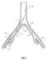
- FIG. 7the introducer with a stent graft mounted onto it according to one embodiment of the present invention is shown schematically.
- the introducer generally shown as 1has an introducer catheter 3 extending over a guide wire catheter 5 .
- the guide wire catheter 5extends from the distal end 7 of the introducer 1 to immediately distal of the nose cone dilator 11 .
- a branched stent graft 13is retained at its proximal end by a retention arrangement (see FIGS. 12 and 13 for one example of a proximal retention arrangement) onto the introducer immediately distal of the nose cone dilator 11 .
- the branched stent graft 13is retained at its distal end by another retention arrangement (see FIGS. 14 and 15 for examples of a proximal retention arrangement) onto the introducer.
- a sleeve 15 operated by a sleeve manipulator 17is mounted on the introducer catheter 3 and in the ready to deploy position the sleeve 15 extends over the branched stent graft 13 to the nose cone dilator 11 . As illustrated in FIG. 7 , however, the sleeve 15 is withdrawn so that the branched stent graft is exposed to show detail of the assembly.
- a handle 19 at the distal end of the introducer catheter 3enables manipulation of the introducer 1 .
- An indwelling catheter 21enters a lumen (not shown) of the introducer catheter 3 at the handle 19 and exits from the introducer catheter 3 at the distal end 23 of the branched stent graft 13 .
- the branched stent graft 13has a substantially tubular body with a main lumen through the main tubular body and a side lumen through the branch 25 .
- the indwelling catheter 21enters the lumen of the branch 25 from its distal end 26 and hence it passes outside the main tubular body of the branched stent graft before it enters the branch lumen.
- the indwelling catheterthen exits from the main body adjacent the nose cone dilator and extends along the side of the nose cone dilator in a groove 27 in the nose cone dilator.
- a guide wire 29there is a guide wire 29 .
- This guide wire 29can be pushed through the indwelling catheter so that it extends beyond the tip 31 of the nose cone dilator so that it can be snared as will be discussed in relation to FIGS. 1 to 6 showing one embodiment of the stent graft placement procedure.
- the tip 32 of the indwelling catheteris tapered around the guide wire 29 to prevent blood loss through the indwelling catheter.
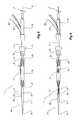
- FIGS. 1 to 6Now looking at FIGS. 1 to 6 , it will be seen that there is schematically illustrated a series of arteries within the human body, although as discussed earlier, the invention is not restricted to this particular application.
- a descending aorta 40extends down to an aortic bifurcation 42 from which extend common iliac arteries 44 and 46 .
- common iliac arteries 44 and 46From each of the common iliac arteries an internal iliac artery 48 and 50 , respectively, extends.
- the internal iliac arteries 48 and 50cannot be practically accessed from their distal ends remote from the junction with the common iliac artery.
- a guide wire 50 for the deployment device 52has been extended into a femoral artery via a femoral incision (not shown) and extended up beyond the aortic bifurcation 42 to the aorta 40 .
- the introducer 1has then been deployed over the guide wire with the nose cone dilator 11 extending nearly up to the aortic bifurcation.
- the sleeve 15 on the deployment deviceextends up to the nose cone dilator 11 but has been withdrawn slightly to expose the proximal end 32 of the indwelling catheter 21 .
- the guide wire 29 from the indwelling catheter 21has been extended so that it extends up beyond the aortic bifurcation but only a short distance up the aorta 40 .
- a snare catheter 52has been deployed via the contra-lateral iliac artery 46 and by suitable radiographic techniques the loop 54 of the snare catheter 52 is used to catch the guide wire 29 .
- FIG. 2Ashows an alternative step in the process. I this step the indwelling catheter 21 and the guide wire 29 have been advanced together to the aortic bifurcation 42 and so that the indwelling catheter 21 is beyond the nose cone dilator 11 . The guide wire 29 is then advance so that it can be snared by the loop 54 of the snare catheter. By this alternative step the guide wire 29 is held more firmly and there is less likelihood that it will become entangled with the main guide wire 50 .
- the guide wire 29has been withdrawn through the contra-lateral iliac artery 46 and the indwelling catheter 21 has been advanced over the guide wire so that it extends over the aortic bifurcation 42 and down the contra-lateral iliac artery 46 .
- the sheath 15has been withdrawn to the distal end 23 of the branched stent graft 13 so that it is just distal of the proximal end of the introducer catheter 3 .
- the branched stent graft 13is partially freed but is still retained by retention arrangements at at least the proximal and distal ends of the branched stent graft and is hence in an unexpanded or not fully expanded condition.
- FIG. 4shows the next stage of the process where a sheath 58 of a suitable size has been advanced over the guide wire 29 via the contra-lateral artery and indwelling catheter 21 so that it enters the proximal end 60 of the branched stent graft 13 .
- the indwelling catheter and guide wire 29still extends down the iliac artery 44 on the introducer 1 so that the sheath 58 can be manipulated to successfully enter the proximal end of the branched stent graft so that it extends towards and into the branch 25 on the stent graft 13 .
- the indwelling catheter 21 and guide wire 19can be withdrawn either from the contra-lateral iliac artery 46 or from the iliac artery 44 and another guide wire 62 introduced via the sheath 58 .
- This guide wire 62can then be manipulated so that it enters the internal iliac artery 48 .
- a further deployment device 63can then be introduced via the sheath 58 from the contra-lateral iliac artery 46 to extend out of the distal end of the branch 25 of the branched stent graft 13 so that a leg extension 64 can be deployed to extend from the branch 25 of the branched stent graft 13 .
- the sheath 58 from the contra-lateral iliac artery 46can then be withdrawn and the release mechanisms at each end of the stent graft 13 can be released and the leg extension 64 released so that the branched stent graft with leg extension is then deployed in the common iliac artery.
- the introducer 1can then be withdrawn although in some situations it may be desirable to leave the sleeve 15 in position so that further deployment of a stent graft into the aorta such as a bifurcated stent graft can be achieved through the sheath 15 .
- the steps in the graft placement procedure accordingly using the device of the present inventionmay be as follows:
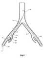
- FIGS. 8 and 9an introducer with a stent graft mounted onto it according to an alternative embodiment of the present invention is shown schematically.
- the same reference numeralsare used for corresponding features to those of FIG. 7 .
- the introducer generally shown as 1has an introducer catheter 3 extending over a guide wire catheter 5 .
- the guide wire catheter 5extends from the distal end 7 of the introducer 1 to immediately distal of the nose cone dilator 11 which is at the proximal end 9 of the introducer.
- a fenestrated stent graft 70is retained by a retention arrangement (not shown) onto the introducer immediately distal of the nose cone dilator 11 .
- a sleeve 15 operated by a sleeve manipulator 17is mounted on the introducer catheter 3 and in the ready to deploy position the sleeve 15 extends over the stent graft 70 to the nose cone dilator 11 . As illustrated in FIG.
- a handle 19 at the distal end of the introducer catheter 3enables manipulation of the introducer 1 .
- An indwelling catheter 21enters a lumen (not shown) of the introducer catheter 3 at the handle 19 and exits from the introducer catheter at the distal end 23 of the stent graft 70 .
- the stent graft 70has a substantially tubular body with a main lumen through the main tubular body and a fenestration 71 .
- the indwelling catheter 21enters the fenestration 71 from outside the stent graft and hence it passes outside the main tubular body of the stent graft at the distal end thereof, before it enters fenestration.
- the indwelling catheterthen passes through the main lumen of the stent graft to its proximal end and exits from the main body adjacent the nose cone dilator 11 and extends along the side of the nose cone dilator in a groove 27 in the nose cone dilator.
- a guide wire 29there is a guide wire 29 .
- This guide wire 29can be pushed through the indwelling catheter so that it extends beyond the tip 31 of the nose cone dilator so that it can be snared as discussed in relation to FIGS. 1 to 6 showing a stent graft placement procedure.
- the tip 32 of the indwelling catheteris tapered around the guide wire 29 to prevent blood loss through the indwelling catheter.
- FIG. 10shows a stage of deployment of the stent graft as shown in FIGS. 8 and 9 corresponding to the stage of deployment shown in FIG. 5 above.
- the same reference numeralare used for corresponding features to those of FIGS. 1 to 6 .
- a guide wire 50 for the deployment device 52has been extended into a femoral artery via a femoral incision (not shown) and extended up beyond the aortic bifurcation 42 into the aorta 40 .
- An introducer 1has then been deployed over the guide wire with the nose cone dilator 11 extending nearly up to the aortic bifurcation.
- the sleeve 15 on the deployment deviceextends up to the nose cone dilator but has been withdrawn slightly to expose the proximal end of the indwelling catheter 21 .
- a guide wire from an indwelling catheter(not shown in FIG.
- a snare catheterhas been deployed via the contra-lateral iliac artery 46 and by suitable radiographic techniques the loop of the snare catheter has been used to catch the guide wire.
- the guide wirehas then been withdrawn through the contra-lateral iliac artery 46 and the indwelling catheter has been advanced over the guide wire so that it extends over the aortic bifurcation 42 and down the contra-lateral iliac artery 46 .
- the sheath 15has been withdrawn to just distal of the fenestration 25 and still covering the distal end 23 of the stent graft 70 .
- the stent graft 13is partially freed but is still retained by a retention arrangements at the proximal end 60 of the stent graft and by the sheath at the distal end.
- the exposed portion of the stent graft between the proximal end and the fenestrationcan expand although there may be diameter reducing ties (not shown) to restrict the amount of expansion.
- a sheath 58 of a suitable sizehas been advanced over the guide wire 29 and indwelling catheter 21 so that it enters the proximal end 60 of the branched stent graft 70 .
- the indwelling catheter and guide wire 29still extends down the iliac artery 44 on the introducer 1 so that the sheath 58 can be manipulated to successfully enter the proximal end of the branched stent graft 60 so that it extends towards and into the fenestration 71 on the stent graft 70 .
- the indwelling catheter 21 and guide wire 19can be withdrawn, either from the contra-lateral iliac artery 46 , or from the iliac artery 44 and another guide wire 62 introduced via the sheath 58 .
- This guide wire 62can then be manipulated so that it enters the internal iliac artery 48 .
- a further deployment device 63has then been introduced via the sheath 58 from the contra-lateral iliac artery 46 to extend out of the fenestration 71 of the stent graft 70 .
- the further deployment device 63carries a leg extension 64 .
- the leg extension 64can be deployed to extend from the fenestration 71 of the stent graft 70 .
- the leg extension 64can be a covered balloon expandable stent for instance, which is carried on a balloon in the deployment device so that it can be deployed and expanded with its proximal end retained in the fenestration and extending into the internal iliac artery 48 .
- FIG. 11an introducer with a stent graft mounted onto it according to an alternative embodiment of the present invention is shown schematically.
- the stent graft 90has a fenestration 94 in the wall of the stent graft 90 and an internal leg extension 92 extending inwardly and toward the proximal end 74 of the stent graft 90 from the fenestration 94 .
- the indwelling catheter 80extends into the fenestration 94 and into the internal leg extension 92 and toward the proximal end 74 of the stent graft 90 .
- the indwelling catheter 80then exits from the main body adjacent the nose cone dilator 82 and extends along the side of the nose cone dilator 82 in a groove 81 in the nose cone dilator 82 .
- FIGS. 8 to 11show various embodiments of the present invention in a stylised manner. It should be noted that the configuration with the main sheath withdrawn completely off the stent graft but with the indwelling catheter and guide wire in its initial position would not occur in practice.
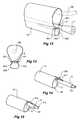
- FIG. 12shows a side view of one method of proximal retention suitable for the present invention
- FIG. 13shows a cross sectional view of the arrangement shown in FIG. 12 .
- the same reference numeralsare used for corresponding features to those of FIG. 7 for corresponding items.
- the guide wire catheter 5extends to a nose cone dilator 11 and the proximal end of the stent graft 13 is retained onto the guide wire catheter just distal of the nose cone dilator. Retention is by means of a pair loops of suture material 101 each of which is engaged with a trigger wire 103 extending from an aperture in the guide wire catheter 5 .
- the loopsare placed so that there is formed a smaller 105 and larger fold 107 of the stent graft 13 at its proximal end.
- the indwelling catheterpasses through the region defined by the larger fold 107 and therefore when the sheath 58 (see FIG. 4 ) has been advanced over the guide wire then it can more easily enter the lumen of the stent graft.
- FIG. 14shows a side view of one method of distal retention suitable for the present invention.
- the same reference numeralsare used for corresponding features to those of FIG. 7 for corresponding items.
- the distal end 23 of the stent graft 13is retained onto the guide wire catheter 5 just proximal of the deployment catheter 3 by means of a suture loop 109 engaged into the stent graft 13 and a loop of trigger wire 111 extending from the deployment catheter 3 . Removal of the trigger wire 111 when required will release the distal end 23 of the stent graft 13 .
- FIG. 15shows a side view of an alternative method of distal retention suitable for the present invention.
- the same reference numeralsare used for corresponding features to those of FIG. 7 for corresponding items.
- the distal end 23 of the stent graft 13is retained onto the guide wire catheter 5 just proximal of the deployment catheter 3 by means a loop of trigger wire 113 extending from the deployment catheter 3 and passing through a portion of the stent graft 13 . Removal of the trigger wire 113 when required will release the distal end 23 of the stent graft 13 .
Landscapes
- Health & Medical Sciences (AREA)
- Engineering & Computer Science (AREA)
- Biomedical Technology (AREA)
- Cardiology (AREA)
- Oral & Maxillofacial Surgery (AREA)
- Transplantation (AREA)
- Heart & Thoracic Surgery (AREA)
- Vascular Medicine (AREA)
- Life Sciences & Earth Sciences (AREA)
- Animal Behavior & Ethology (AREA)
- General Health & Medical Sciences (AREA)
- Public Health (AREA)
- Veterinary Medicine (AREA)
- Gastroenterology & Hepatology (AREA)
- Pulmonology (AREA)
- Prostheses (AREA)
- Media Introduction/Drainage Providing Device (AREA)
Abstract
Description
- 1. Deploy an introducer into a femoral artery via a femoral incision and extend the introducer up to the aortic bifurcation.
- 2. Withdraw the sheath to expose the proximal end of an indwelling catheter associated with the introducer.
- 3. Advance an indwelling guide wire through the indwelling catheter beyond the nose cone dilator of the introducer.
- 4. Introduce a snare catheter into the contra-lateral iliac artery via a femoral route and snare the indwelling guide wire.
- 5. Withdraw the indwelling guide wire through the contra-lateral iliac artery and advance the indwelling catheter around the aortic bifurcation to protect the aortic bifurcation during subsequent steps.
- 6. Withdraw the main sheath to expose the branched stent graft but still have the branched stent graft retained at each of its ends.
- 7. Deploy an auxiliary sheath over the indwelling guide wire up the contra-lateral iliac artery and into the branched stent graft via the proximal end of the branched stent graft.
- 8. Advance the auxiliary sheath into the short leg of the branched stent graft via the indwelling catheter guide wire or another guide wire which has been deployed through the sheath which has been placed via the contra-lateral iliac artery.
- 9. Remove the indwelling catheter and indwelling guide wire.
- 10. Advance a guide wire through the auxiliary sheath via the contra-lateral iliac artery and manipulate it into the internal iliac artery. At this stage, it may be necessary to withdraw the deployment device or rotate it slightly to guide the branch of the branched stent graft towards the internal iliac artery.
- 11. Advance a short leg introducer with a leg stent graft over the guide wire in the contra-lateral iliac artery and through the auxiliary sheath and into the internal iliac artery.
- 12. Release the proximal distal ends of the branched stent graft
- 13. Release the leg stent graft from the short leg introducer or balloon expand the leg stent graft.
- 14. Withdraw the contra-lateral iliac artery auxiliary sheath, introducer and guide wire.
- 15. Withdraw the main introducer.
Claims (2)
Priority Applications (12)
| Application Number | Priority Date | Filing Date | Title |
|---|---|---|---|
| US10/962,763US8012193B2 (en) | 2003-10-14 | 2004-10-12 | Introducer for an iliac side branch device |
| US11/713,388US7998186B2 (en) | 2003-10-14 | 2007-03-02 | Introducer for a side branch device |
| US13/181,285US9770321B2 (en) | 2003-10-14 | 2011-07-12 | Introducer for a side branch device |
| US13/181,249US20110270375A1 (en) | 2003-10-14 | 2011-07-12 | Introducer for an iliac side branch device |
| US14/469,247US9603734B2 (en) | 2003-10-14 | 2014-08-26 | Introducer for an iliac side branch device |
| US14/469,268US9788982B2 (en) | 2003-10-14 | 2014-08-26 | Introducer for an iliac side branch device |
| US14/469,259US9808365B2 (en) | 2003-10-14 | 2014-08-26 | Introducer for an iliac side branch device |
| US14/469,234US9782284B2 (en) | 2003-10-14 | 2014-08-26 | Introducer for an iliac side branch device |
| US15/710,255US10201414B2 (en) | 2003-10-14 | 2017-09-20 | Introducer for a side branch device |
| US15/710,235US10166095B2 (en) | 2003-10-14 | 2017-09-20 | Introducer for a side branch device |
| US16/227,221US20190192276A1 (en) | 2003-10-14 | 2018-12-20 | Introducer for a side branch device |
| US16/256,623US11229537B2 (en) | 2003-10-14 | 2019-01-24 | Introducer for a side branch device |
Applications Claiming Priority (3)
| Application Number | Priority Date | Filing Date | Title |
|---|---|---|---|
| US51082303P | 2003-10-14 | 2003-10-14 | |
| US60148504P | 2004-08-13 | 2004-08-13 | |
| US10/962,763US8012193B2 (en) | 2003-10-14 | 2004-10-12 | Introducer for an iliac side branch device |
Related Child Applications (2)
| Application Number | Title | Priority Date | Filing Date |
|---|---|---|---|
| US11/713,388Continuation-In-PartUS7998186B2 (en) | 2003-10-14 | 2007-03-02 | Introducer for a side branch device |
| US13/181,249DivisionUS20110270375A1 (en) | 2003-10-14 | 2011-07-12 | Introducer for an iliac side branch device |
Publications (2)
| Publication Number | Publication Date |
|---|---|
| US20050182476A1 US20050182476A1 (en) | 2005-08-18 |
| US8012193B2true US8012193B2 (en) | 2011-09-06 |
Family
ID=34467977
Family Applications (7)
| Application Number | Title | Priority Date | Filing Date |
|---|---|---|---|
| US10/962,763Active2027-10-31US8012193B2 (en) | 2003-10-14 | 2004-10-12 | Introducer for an iliac side branch device |
| US13/181,249AbandonedUS20110270375A1 (en) | 2003-10-14 | 2011-07-12 | Introducer for an iliac side branch device |
| US14/469,247Expired - LifetimeUS9603734B2 (en) | 2003-10-14 | 2014-08-26 | Introducer for an iliac side branch device |
| US14/469,234Expired - LifetimeUS9782284B2 (en) | 2003-10-14 | 2014-08-26 | Introducer for an iliac side branch device |
| US14/469,259Active2026-02-20US9808365B2 (en) | 2003-10-14 | 2014-08-26 | Introducer for an iliac side branch device |
| US14/469,268Active2025-12-06US9788982B2 (en) | 2003-10-14 | 2014-08-26 | Introducer for an iliac side branch device |
| US16/256,623Expired - LifetimeUS11229537B2 (en) | 2003-10-14 | 2019-01-24 | Introducer for a side branch device |
Family Applications After (6)
| Application Number | Title | Priority Date | Filing Date |
|---|---|---|---|
| US13/181,249AbandonedUS20110270375A1 (en) | 2003-10-14 | 2011-07-12 | Introducer for an iliac side branch device |
| US14/469,247Expired - LifetimeUS9603734B2 (en) | 2003-10-14 | 2014-08-26 | Introducer for an iliac side branch device |
| US14/469,234Expired - LifetimeUS9782284B2 (en) | 2003-10-14 | 2014-08-26 | Introducer for an iliac side branch device |
| US14/469,259Active2026-02-20US9808365B2 (en) | 2003-10-14 | 2014-08-26 | Introducer for an iliac side branch device |
| US14/469,268Active2025-12-06US9788982B2 (en) | 2003-10-14 | 2014-08-26 | Introducer for an iliac side branch device |
| US16/256,623Expired - LifetimeUS11229537B2 (en) | 2003-10-14 | 2019-01-24 | Introducer for a side branch device |
Country Status (3)
| Country | Link |
|---|---|
| US (7) | US8012193B2 (en) |
| EP (5) | EP1691719B1 (en) |
| WO (1) | WO2005037141A2 (en) |
Cited By (28)
| Publication number | Priority date | Publication date | Assignee | Title |
|---|---|---|---|---|
| US20070123910A1 (en)* | 2005-11-16 | 2007-05-31 | William A. Cook Australia Pty Ltd. | Stent graft introducer |
| US20090125095A1 (en)* | 2007-11-01 | 2009-05-14 | Cook Incorporated | Flexible stent graft |
| US20100198328A1 (en)* | 2009-02-02 | 2010-08-05 | William A. Cook Australia Pty. Ltd. | Preloaded Stent Graft Delivery Device |
| US8480726B2 (en) | 2011-02-28 | 2013-07-09 | Cook Medical Technologies Llc | Stent graft with valve arrangement |
| US8709068B2 (en) | 2007-03-05 | 2014-04-29 | Endospan Ltd. | Multi-component bifurcated stent-graft systems |
| US8945200B1 (en)* | 2011-11-16 | 2015-02-03 | W. L. Gore & Associates, Inc. | Iliac bifurcated endoprosthesis medical apparatus and method of deploying same |
| US9220614B2 (en) | 2013-03-11 | 2015-12-29 | Cook Medical Technologies Llc | Endovascular grafts for treating the iliac arteries and methods of delivery and deployment thereof |
| US9427339B2 (en) | 2011-10-30 | 2016-08-30 | Endospan Ltd. | Triple-collar stent-graft |
| US9439793B2 (en) | 2013-03-12 | 2016-09-13 | Cook Medical Technologies Llc | Extension for iliac branch delivery device and methods of using the same |
| US9522073B2 (en) | 2012-02-08 | 2016-12-20 | Cook Medical Technologies Llc | Orientation markers for endovascular delivery system |
| US9545324B2 (en) | 2013-03-13 | 2017-01-17 | Cook Medical Technologies Llc | Pre-loaded iliac branch device and methods of deployment |
| US9597204B2 (en) | 2011-12-04 | 2017-03-21 | Endospan Ltd. | Branched stent-graft system |
| US9770321B2 (en) | 2003-10-14 | 2017-09-26 | Cook Medical Technologies Llc | Introducer for a side branch device |
| US9770350B2 (en) | 2012-05-15 | 2017-09-26 | Endospan Ltd. | Stent-graft with fixation elements that are radially confined for delivery |
| US9782284B2 (en) | 2003-10-14 | 2017-10-10 | Cook Medical Technologies Llc | Introducer for an iliac side branch device |
| EP3245986A1 (en) | 2016-03-24 | 2017-11-22 | Cook Medical Technologies LLC | Wire retention and release mechanisms |
| US9839510B2 (en) | 2011-08-28 | 2017-12-12 | Endospan Ltd. | Stent-grafts with post-deployment variable radial displacement |
| US9918825B2 (en) | 2009-06-23 | 2018-03-20 | Endospan Ltd. | Vascular prosthesis for treating aneurysms |
| US9956101B2 (en) | 2014-12-04 | 2018-05-01 | Trivascular, Inc. | Internal iliac preservation devices and methods |
| US9993360B2 (en) | 2013-01-08 | 2018-06-12 | Endospan Ltd. | Minimization of stent-graft migration during implantation |
| US10130501B2 (en) | 2013-03-12 | 2018-11-20 | Cook Medical Technologies Llc | Delivery device with an extension sheath and methods of using the same |
| US10143576B2 (en) | 2006-04-19 | 2018-12-04 | Cook Medical Technologies Llc | Twin bifurcated stent graft |
| US10470871B2 (en) | 2001-12-20 | 2019-11-12 | Trivascular, Inc. | Advanced endovascular graft |
| US10485684B2 (en) | 2014-12-18 | 2019-11-26 | Endospan Ltd. | Endovascular stent-graft with fatigue-resistant lateral tube |
| US10603197B2 (en) | 2013-11-19 | 2020-03-31 | Endospan Ltd. | Stent system with radial-expansion locking |
| US11096810B2 (en) | 2017-11-29 | 2021-08-24 | Cook Medical Technologies Llc | Preloaded pusher tip for endografts |
| US11324618B2 (en) | 2017-02-28 | 2022-05-10 | Cook Medical Technologies Llc | Delivery system for a preloaded fenestrated device having a ratcheted wire release |
| US11672682B2 (en) | 2012-02-14 | 2023-06-13 | W. L. Gore & Associates, Inc. | Endoprosthesis having aligned legs for ease of cannulation |
Families Citing this family (89)
| Publication number | Priority date | Publication date | Assignee | Title |
|---|---|---|---|---|
| US9125733B2 (en) | 2003-01-14 | 2015-09-08 | The Cleveland Clinic Foundation | Branched vessel endoluminal device |
| EP1791498B1 (en)* | 2004-09-22 | 2018-02-28 | Cook Medical Technologies, LLC | Stent graft with integral side arm |
| US8287583B2 (en) | 2005-01-10 | 2012-10-16 | Taheri Laduca Llc | Apparatus and method for deploying an implantable device within the body |
| US8128680B2 (en) | 2005-01-10 | 2012-03-06 | Taheri Laduca Llc | Apparatus and method for deploying an implantable device within the body |
| WO2008098255A2 (en) | 2007-02-09 | 2008-08-14 | Taheri Laduca Llc | Apparatus and method for deploying an implantable device within the body |
| US8162894B2 (en)* | 2005-09-09 | 2012-04-24 | Cook Medical Technologies Llc | Valve opener |
| JP5181211B2 (en)* | 2005-12-23 | 2013-04-10 | クック・メディカル・テクノロジーズ・リミテッド・ライアビリティ・カンパニー | Trigger wire release mechanism and introducer for prosthesis including the same |
| US20100292771A1 (en)* | 2009-05-18 | 2010-11-18 | Syncardia Systems, Inc | Endovascular stent graft system and guide system |
| GB0617219D0 (en) | 2006-08-31 | 2006-10-11 | Barts & London Nhs Trust | Blood vessel prosthesis and delivery apparatus |
| US8523931B2 (en)* | 2007-01-12 | 2013-09-03 | Endologix, Inc. | Dual concentric guidewire and methods of bifurcated graft deployment |
| US20080288045A1 (en)* | 2007-02-22 | 2008-11-20 | Mohsin Saeed | Apparatus and method for implantation of a bifurcated endovascular prosthesis |
| US8821567B2 (en)* | 2007-02-22 | 2014-09-02 | Mohsin Saeed | Apparatus and method for implantation of a bifurcated endovascular prosthesis |
| US8118862B2 (en)* | 2007-02-22 | 2012-02-21 | Mohsin Saeed | Apparatus and method for implantation of bifurcated endovascular prosthesis |
| JP5261725B2 (en)* | 2007-03-06 | 2013-08-14 | ウィリアム・エイ・クック・オーストラリア・プロプライエタリー・リミテッド | Intravascular placement device |
| US8273115B2 (en)* | 2007-04-24 | 2012-09-25 | W. L. Gore & Associates, Inc. | Side branched endoluminal prostheses and methods of delivery thereof |
| US10646363B2 (en)* | 2007-12-27 | 2020-05-12 | Cook Medical Technologies Llc | Endovascular device delivery system |
| GB0803302D0 (en) | 2008-02-22 | 2008-04-02 | Barts & London Nhs Trust | Blood vessel prosthesis and delivery apparatus |
| WO2009105699A1 (en) | 2008-02-22 | 2009-08-27 | Endologix, Inc. | Design and method of placement of a graft or graft system |
| US8236040B2 (en) | 2008-04-11 | 2012-08-07 | Endologix, Inc. | Bifurcated graft deployment systems and methods |
| WO2009148607A1 (en)* | 2008-06-04 | 2009-12-10 | Gore Enterprise Holdings, Inc. | Controlled deployable medical device and method of making the same |
| CA2727000C (en) | 2008-06-04 | 2014-01-07 | Gore Enterprise Holdings, Inc. | Controlled deployable medical device and method of making the same |
| EP2520320B1 (en) | 2008-07-01 | 2016-11-02 | Endologix, Inc. | Catheter system |
| EP2331011B1 (en)* | 2008-08-29 | 2015-01-14 | Cook Medical Technologies LLC | Prosthesis with moveable fenestration |
| US8137398B2 (en)* | 2008-10-13 | 2012-03-20 | Medtronic Ventor Technologies Ltd | Prosthetic valve having tapered tip when compressed for delivery |
| CN101836911A (en) | 2009-03-18 | 2010-09-22 | 微创医疗器械(上海)有限公司 | Collateral filmed stent |
| US20110054587A1 (en) | 2009-04-28 | 2011-03-03 | Endologix, Inc. | Apparatus and method of placement of a graft or graft system |
| CN101897629B (en)* | 2009-05-26 | 2013-08-07 | 上海微创医疗器械(集团)有限公司 | Branched membrane-covered support conveying system and conveying method thereof |
| GB2481357B (en)* | 2009-05-26 | 2016-12-14 | Microport Endovascular (Shanghai) Co Ltd | Delivery system for branched stent graft |
| US9095456B2 (en) | 2009-10-13 | 2015-08-04 | Cook Medical Technologies Llc | Paraplegia prevention stent graft |
| EP3034036B1 (en) | 2009-10-13 | 2019-09-11 | Cook Medical Technologies LLC | Paraplegia prevention stent graft |
| US20120253387A1 (en)* | 2009-12-02 | 2012-10-04 | Apica Cardiovascular Ireland Limited | Device system and method for tissue access site closure |
| CN102370532B (en)* | 2010-08-13 | 2015-06-17 | 黄连军 | Collateral type tectorial membrane support frame conveyor as well as installing method |
| US8771336B2 (en) | 2010-08-21 | 2014-07-08 | Cook Medical Technologies Llc | Endoluminal prosthesis comprising a valve replacement and at least one fenestration |
| US8702786B2 (en) | 2010-08-21 | 2014-04-22 | Cook Medical Technologies Llc | Prosthesis having pivoting fenestration |
| US8870939B2 (en) | 2010-08-21 | 2014-10-28 | Cook Medical Technologies Llc | Prosthesis having pivoting fenestration |
| CA2748206C (en) | 2010-08-21 | 2015-06-23 | Blayne A. Roeder | Prosthesis having pivoting fenestration |
| US20120109279A1 (en) | 2010-11-02 | 2012-05-03 | Endologix, Inc. | Apparatus and method of placement of a graft or graft system |
| JP5944914B2 (en) | 2010-11-15 | 2016-07-05 | エンドバスキュラー ディベロップメント アクティエボラーグ | Assembly with guide wire and fixator for attachment to a blood vessel |
| US8535371B2 (en) | 2010-11-15 | 2013-09-17 | Endovascular Development AB | Method of positioning a tubular element in a blood vessel of a person |
| US20120130475A1 (en) | 2010-11-16 | 2012-05-24 | Shaw Edward E | Sleeves for expandable medical devices |
| US8808350B2 (en) | 2011-03-01 | 2014-08-19 | Endologix, Inc. | Catheter system and methods of using same |
| EP3583916B1 (en) | 2011-04-28 | 2023-12-06 | Cook Medical Technologies LLC | Apparatus for facilitating deployment of an endoluminal prosthesis |
| US8551158B2 (en) | 2011-05-13 | 2013-10-08 | Cook Medical Technologies Llc | Steerable iliac branch device |
| US10213329B2 (en) | 2011-08-12 | 2019-02-26 | W. L. Gore & Associates, Inc. | Evertable sheath devices, systems, and methods |
| CN103732181B (en) | 2011-08-12 | 2016-05-04 | W.L.戈尔及同仁股份有限公司 | Be used for the device of the cross-sectional profiles of the approximate vascular system with branch |
| US8728148B2 (en) | 2011-11-09 | 2014-05-20 | Cook Medical Technologies Llc | Diameter reducing tie arrangement for endoluminal prosthesis |
| US9877858B2 (en) | 2011-11-14 | 2018-01-30 | W. L. Gore & Associates, Inc. | External steerable fiber for use in endoluminal deployment of expandable devices |
| US9782282B2 (en) | 2011-11-14 | 2017-10-10 | W. L. Gore & Associates, Inc. | External steerable fiber for use in endoluminal deployment of expandable devices |
| US10213187B1 (en) | 2012-01-25 | 2019-02-26 | Mubin I. Syed | Method and apparatus for percutaneous superficial temporal artery access for carotid artery stenting |
| US9375308B2 (en) | 2012-03-13 | 2016-06-28 | W. L. Gore & Associates, Inc. | External steerable fiber for use in endoluminal deployment of expandable devices |
| US8968384B2 (en)* | 2012-04-27 | 2015-03-03 | Medtronic Vascular, Inc. | Circumferentially constraining sutures for a stent-graft |
| WO2014081947A1 (en) | 2012-11-21 | 2014-05-30 | Syed Mubin I | System for the intravascular placement of a medical device |
| AU2012258394B1 (en) | 2012-11-27 | 2013-03-07 | Cook Medical Technologies Llc | Stent graft having a closeable fenestration |
| US10039657B2 (en)* | 2012-12-21 | 2018-08-07 | CARDINAL HEALTH SWITZERLAND 515 GmbH | Cannulation guiding device for bifurcated stent and method of use |
| US9907641B2 (en) | 2014-01-10 | 2018-03-06 | W. L. Gore & Associates, Inc. | Implantable intraluminal device |
| US9763819B1 (en) | 2013-03-05 | 2017-09-19 | W. L. Gore & Associates, Inc. | Tapered sleeve |
| US9987155B1 (en) | 2013-03-07 | 2018-06-05 | W. L. Gore & Associates, Inc. | Implantable medical devices and related delivery systems |
| US10265202B2 (en) | 2013-03-14 | 2019-04-23 | Cook Medical Technologies Llc | Prosthesis having an everting pivoting fenestration |
| US9179999B2 (en)* | 2013-06-06 | 2015-11-10 | Med-Genesis, Llc | Apparatus and method for installing a stent |
| AU2013206712B1 (en) | 2013-07-03 | 2013-11-28 | Cook Medical Technologies Llc | Endovascular graft having a cannulation pocket |
| US10524944B1 (en) | 2014-01-29 | 2020-01-07 | W. L. Gore & Associates, Inc. | Delivery systems and methods of endoluminal delivery of branched vascular endoprosthetic devices |
| US10966850B2 (en) | 2014-03-06 | 2021-04-06 | W. L. Gore & Associates, Inc. | Implantable medical device constraint and deployment apparatus |
| US9974675B2 (en) | 2014-04-04 | 2018-05-22 | W. L. Gore & Associates, Inc. | Delivery and deployment systems for bifurcated stent grafts |
| US9833346B2 (en) | 2014-04-04 | 2017-12-05 | W. L. Gore & Associates, Inc. | Deployment handle for a medical device deployment system |
| US10478324B2 (en) | 2014-08-12 | 2019-11-19 | W. L. Gore & Associates, Inc. | Handle for medical device deployment |
| US9636244B2 (en) | 2015-04-09 | 2017-05-02 | Mubin I. Syed | Apparatus and method for proximal to distal stent deployment |
| WO2017004265A1 (en) | 2015-06-30 | 2017-01-05 | Endologix, Inc. | Locking assembly for coupling guidewire to delivery system |
| US10034785B1 (en) | 2015-10-13 | 2018-07-31 | W. L. Gore & Associates, Inc. | Single site access aortic aneurysm repair method |
| US9980838B2 (en)* | 2015-10-30 | 2018-05-29 | Ram Medical Innovations Llc | Apparatus and method for a bifurcated catheter for use in hostile aortic arches |
| US10779976B2 (en) | 2015-10-30 | 2020-09-22 | Ram Medical Innovations, Llc | Apparatus and method for stabilization of procedural catheter in tortuous vessels |
| US10327929B2 (en) | 2015-10-30 | 2019-06-25 | Ram Medical Innovations, Llc | Apparatus and method for stabilization of procedural catheter in tortuous vessels |
| US10492936B2 (en) | 2015-10-30 | 2019-12-03 | Ram Medical Innovations, Llc | Apparatus and method for improved access of procedural catheter in tortuous vessels |
| US11020256B2 (en) | 2015-10-30 | 2021-06-01 | Ram Medical Innovations, Inc. | Bifurcated “Y” anchor support for coronary interventions |
| US10512533B1 (en) | 2016-02-23 | 2019-12-24 | W. L. Gore & Associates, Inc. | Branched graft assembly method in vivo |
| US10173031B2 (en) | 2016-06-20 | 2019-01-08 | Mubin I. Syed | Interchangeable flush/selective catheter |
| WO2018027215A1 (en) | 2016-08-05 | 2018-02-08 | W. L. Gore & Associates, Inc. | Integrated medical device constraining lumen |
| JP6940594B2 (en) | 2016-08-24 | 2021-09-29 | ダブリュ.エル.ゴア アンド アソシエイツ,インコーポレイティドW.L. Gore & Associates, Incorporated | Sleeve for dilated medical devices |
| WO2018045097A1 (en)* | 2016-08-31 | 2018-03-08 | Endologix, Inc. | Systems and methods with stent and filling structure |
| AU2017326087B2 (en) | 2016-09-15 | 2020-03-26 | W. L. Gore & Associates, Inc. | Staged deployment of expandable implant |
| CA3206418A1 (en) | 2017-02-14 | 2018-08-23 | W. L. Gore & Associates, Inc. | Implantable medical device delivery systems and methods |
| WO2018157243A1 (en) | 2017-03-01 | 2018-09-07 | Power Adam | Looped wire for advanced stent grafts and methods of using same |
| CA3055567C (en) | 2017-03-08 | 2021-11-23 | W. L. Gore & Associates, Inc. | Steering wire attach for angulation |
| EP3694450B1 (en) | 2017-10-11 | 2023-08-02 | W. L. Gore & Associates, Inc. | Implantable medical device constraint and deployment apparatus |
| US11007075B2 (en) | 2018-02-18 | 2021-05-18 | Ram Medical Innovations, Inc. | Vascular access devices and methods for lower limb interventions |
| WO2020030075A1 (en)* | 2018-08-09 | 2020-02-13 | 杭州唯强医疗科技有限公司 | Delivery apparatus |
| CN110811946B (en)* | 2018-08-09 | 2025-07-11 | 杭州唯强医疗科技有限公司 | A conveying device |
| AU2018439076B2 (en) | 2018-08-31 | 2022-07-07 | W. L. Gore & Associates, Inc. | Apparatus, system, and method for steering an implantable medical device |
| US12268619B2 (en) | 2019-10-15 | 2025-04-08 | Merit Medical Systems, Inc. | Endovascular prosthesis with selectively openable internal duct |
| US11311397B2 (en) | 2019-10-23 | 2022-04-26 | Medtronic Vascular, Inc. | Branch stent graft and delivery method for endovascular treatment of the iliac artery aneurysms |
Citations (22)
| Publication number | Priority date | Publication date | Assignee | Title |
|---|---|---|---|---|
| US5387235A (en) | 1991-10-25 | 1995-02-07 | Cook Incorporated | Expandable transluminal graft prosthesis for repair of aneurysm |
| US5628783A (en)* | 1991-04-11 | 1997-05-13 | Endovascular Technologies, Inc. | Bifurcated multicapsule intraluminal grafting system and method |
| US5720776A (en) | 1991-10-25 | 1998-02-24 | Cook Incorporated | Barb and expandable transluminal graft prosthesis for repair of aneurysm |
| US5776142A (en)* | 1996-12-19 | 1998-07-07 | Medtronic, Inc. | Controllable stent delivery system and method |
| US5824055A (en)* | 1997-03-25 | 1998-10-20 | Endotex Interventional Systems, Inc. | Stent graft delivery system and methods of use |
| WO1998053761A1 (en) | 1997-05-26 | 1998-12-03 | William A. Cook Australia Pty. Ltd. | A prosthesis and a method and means of deploying a prosthesis |
| WO1999029262A1 (en) | 1997-12-10 | 1999-06-17 | William A. Cook Australia Pty. Ltd. | Endoluminal aortic stents |
| US6206931B1 (en) | 1996-08-23 | 2001-03-27 | Cook Incorporated | Graft prosthesis materials |
| US20010012943A1 (en)* | 1998-12-11 | 2001-08-09 | Shaolian Samuel M. | Bifurcation graft deployment catheter |
| US20010037142A1 (en)* | 2000-03-14 | 2001-11-01 | Cook Incorporated | Endovascular stent graft |
| US20020045930A1 (en)* | 1995-12-14 | 2002-04-18 | Burg Erik Van Der | Stent-graft deployment apparatus and method |
| US20020143383A1 (en)* | 2001-01-19 | 2002-10-03 | Parodi Juan Carlos | Introducer for deployment of branched prosthesis |
| WO2003034948A1 (en) | 2001-10-26 | 2003-05-01 | Cook Incorporated | Prostheses for curved lumens |
| US20030120332A1 (en) | 2001-12-19 | 2003-06-26 | Cook Incorporated | Stent graft with improved graft adhesion |
| WO2003101518A1 (en) | 2002-05-29 | 2003-12-11 | William A. Cook Australia Pty. Ltd. | Trigger wire system for a prosthesis deployment device |
| US6663666B1 (en)* | 1994-05-12 | 2003-12-16 | Endovascular Technologies, Inc. | Delivery catheter for intraluminally deploying a graft |
| WO2004002365A1 (en) | 2002-06-26 | 2004-01-08 | Cook Incorporated | Stent-graft fastening |
| WO2004002370A1 (en) | 2002-06-28 | 2004-01-08 | Cook Incorporated | Thoracic aortic aneurysm stent graft |
| WO2004017867A1 (en) | 2002-08-23 | 2004-03-04 | William A. Cook Australia Pty. Ltd. | Composite prosthesis |
| WO2004017868A1 (en) | 2002-08-23 | 2004-03-04 | William A. Cook Australia Pty. Ltd. | Asymmetric stent graft attachment |
| WO2004028399A2 (en) | 2002-06-28 | 2004-04-08 | Cook Incorporated | Thoracic deployment device |
| WO2004033566A1 (en) | 2002-10-04 | 2004-04-22 | Eftec Europe Holding Ag | Coating agent |
Family Cites Families (42)
| Publication number | Priority date | Publication date | Assignee | Title |
|---|---|---|---|---|
| CA1232814A (en)* | 1983-09-16 | 1988-02-16 | Hidetoshi Sakamoto | Guide wire for catheter |
| US5693083A (en)* | 1983-12-09 | 1997-12-02 | Endovascular Technologies, Inc. | Thoracic graft and delivery catheter |
| CA2065634C (en)* | 1991-04-11 | 1997-06-03 | Alec A. Piplani | Endovascular graft having bifurcation and apparatus and method for deploying the same |
| EP0687022B1 (en)* | 1992-04-30 | 1999-04-21 | Sony Corporation | Material for anode and method of its manufacture |
| US5609627A (en)* | 1994-02-09 | 1997-03-11 | Boston Scientific Technology, Inc. | Method for delivering a bifurcated endoluminal prosthesis |
| US5556389A (en)* | 1994-03-31 | 1996-09-17 | Liprie; Samuel F. | Method and apparatus for treating stenosis or other constriction in a bodily conduit |
| US5683449A (en) | 1995-02-24 | 1997-11-04 | Marcade; Jean Paul | Modular bifurcated intraluminal grafts and methods for delivering and assembling same |
| US5669924A (en)* | 1995-10-26 | 1997-09-23 | Shaknovich; Alexander | Y-shuttle stent assembly for bifurcating vessels and method of using the same |
| US6325826B1 (en) | 1998-01-14 | 2001-12-04 | Advanced Stent Technologies, Inc. | Extendible stent apparatus |
| US7591846B2 (en)* | 1996-11-04 | 2009-09-22 | Boston Scientific Scimed, Inc. | Methods for deploying stents in bifurcations |
| US6551350B1 (en)* | 1996-12-23 | 2003-04-22 | Gore Enterprise Holdings, Inc. | Kink resistant bifurcated prosthesis |
| US6187033B1 (en) | 1997-09-04 | 2001-02-13 | Meadox Medicals, Inc. | Aortic arch prosthetic graft |
| US5984955A (en) | 1997-09-11 | 1999-11-16 | Wisselink; Willem | System and method for endoluminal grafting of bifurcated or branched vessels |
| US6520988B1 (en)* | 1997-09-24 | 2003-02-18 | Medtronic Ave, Inc. | Endolumenal prosthesis and method of use in bifurcation regions of body lumens |
| EP1039864B1 (en)* | 1997-11-14 | 2006-12-27 | Boston Scientific Limited | Multi-sheath delivery catheter |
| US6099497A (en)* | 1998-03-05 | 2000-08-08 | Scimed Life Systems, Inc. | Dilatation and stent delivery system for bifurcation lesions |
| US6224609B1 (en)* | 1998-03-16 | 2001-05-01 | Teramed Inc. | Bifurcated prosthetic graft |
| US6129738A (en)* | 1998-06-20 | 2000-10-10 | Medtronic Ave, Inc. | Method and apparatus for treating stenoses at bifurcated regions |
| US6368345B1 (en)* | 1998-09-30 | 2002-04-09 | Edwards Lifesciences Corporation | Methods and apparatus for intraluminal placement of a bifurcated intraluminal garafat |
| US6162246A (en) | 1999-02-16 | 2000-12-19 | Barone; Hector Daniel | Aortic graft and method of treating abdominal aortic aneurysms |
| US6261316B1 (en)* | 1999-03-11 | 2001-07-17 | Endologix, Inc. | Single puncture bifurcation graft deployment system |
| US6884258B2 (en)* | 1999-06-04 | 2005-04-26 | Advanced Stent Technologies, Inc. | Bifurcation lesion stent delivery using multiple guidewires |
| US7387639B2 (en)* | 1999-06-04 | 2008-06-17 | Advanced Stent Technologies, Inc. | Short sleeve stent delivery catheter and methods |
| US6383213B2 (en)* | 1999-10-05 | 2002-05-07 | Advanced Cardiovascular Systems, Inc. | Stent and catheter assembly and method for treating bifurcations |
| US20020198585A1 (en) | 1999-10-05 | 2002-12-26 | Willem Wisselink | System and method for edoluminal grafting of bifurcated or branched vessels |
| US6808534B1 (en)* | 2000-02-16 | 2004-10-26 | Endovascular Technologies, Inc. | Collapsible jacket guard |
| WO2002076346A1 (en)* | 2001-03-23 | 2002-10-03 | Hassan Tehrani | Branched aortic arch stent graft |
| US20040138734A1 (en) | 2001-04-11 | 2004-07-15 | Trivascular, Inc. | Delivery system and method for bifurcated graft |
| US6761733B2 (en)* | 2001-04-11 | 2004-07-13 | Trivascular, Inc. | Delivery system and method for bifurcated endovascular graft |
| US6749628B1 (en) | 2001-05-17 | 2004-06-15 | Advanced Cardiovascular Systems, Inc. | Stent and catheter assembly and method for treating bifurcations |
| US7014653B2 (en)* | 2001-12-20 | 2006-03-21 | Cleveland Clinic Foundation | Furcated endovascular prosthesis |
| US6723116B2 (en)* | 2002-01-14 | 2004-04-20 | Syde A. Taheri | Exclusion of ascending/descending aorta and/or aortic arch aneurysm |
| US6949121B1 (en)* | 2002-02-07 | 2005-09-27 | Sentient Engineering & Technology, Llc | Apparatus and methods for conduits and materials |
| EP1487380B1 (en) | 2002-03-25 | 2008-02-27 | Cook Incorporated | Branched vessel prothesis |
| US6858038B2 (en) | 2002-06-21 | 2005-02-22 | Richard R. Heuser | Stent system |
| US20040143286A1 (en) | 2003-01-17 | 2004-07-22 | Johnson Eric G. | Catheter with disruptable guidewire channel |
| EP1608293B1 (en)* | 2003-04-03 | 2015-06-03 | Cook Medical Technologies LLC | Deployment system for a branched stent graft |
| JP4406649B2 (en) | 2003-10-10 | 2010-02-03 | ザ クリーブランド クリニック ファウンデイション | Intraluminal prosthesis for interconnection module related applications |
| US7998186B2 (en) | 2003-10-14 | 2011-08-16 | William A. Cook Australia Pty. Ltd. | Introducer for a side branch device |
| EP1691719B1 (en) | 2003-10-14 | 2016-09-14 | Cook Medical Technologies LLC | Introducer for an iliac side branch device |
| AU2005262541B2 (en) | 2004-06-16 | 2011-04-21 | Cook Incorporated | Thoracic deployment device and stent graft |
| EP1838242A2 (en) | 2005-01-21 | 2007-10-03 | Gen 4, LLC | Modular stent graft employing bifurcated graft and leg locking stent elements |
- 2004
- 2004-10-12EPEP04794818.7Apatent/EP1691719B1/ennot_activeExpired - Lifetime
- 2004-10-12EPEP16150468.3Apatent/EP3031425B1/ennot_activeExpired - Lifetime
- 2004-10-12WOPCT/US2004/033566patent/WO2005037141A2/enactiveSearch and Examination
- 2004-10-12EPEP16150466.7Apatent/EP3028681B1/ennot_activeExpired - Lifetime
- 2004-10-12EPEP16150470.9Apatent/EP3031426B1/ennot_activeExpired - Lifetime
- 2004-10-12EPEP16150469.1Apatent/EP3050542B1/ennot_activeExpired - Lifetime
- 2004-10-12USUS10/962,763patent/US8012193B2/enactiveActive
- 2011
- 2011-07-12USUS13/181,249patent/US20110270375A1/ennot_activeAbandoned
- 2014
- 2014-08-26USUS14/469,247patent/US9603734B2/ennot_activeExpired - Lifetime
- 2014-08-26USUS14/469,234patent/US9782284B2/ennot_activeExpired - Lifetime
- 2014-08-26USUS14/469,259patent/US9808365B2/enactiveActive
- 2014-08-26USUS14/469,268patent/US9788982B2/enactiveActive
- 2019
- 2019-01-24USUS16/256,623patent/US11229537B2/ennot_activeExpired - Lifetime
Patent Citations (36)
| Publication number | Priority date | Publication date | Assignee | Title |
|---|---|---|---|---|
| US5628783A (en)* | 1991-04-11 | 1997-05-13 | Endovascular Technologies, Inc. | Bifurcated multicapsule intraluminal grafting system and method |
| US5720776A (en) | 1991-10-25 | 1998-02-24 | Cook Incorporated | Barb and expandable transluminal graft prosthesis for repair of aneurysm |
| US5387235A (en) | 1991-10-25 | 1995-02-07 | Cook Incorporated | Expandable transluminal graft prosthesis for repair of aneurysm |
| US6663666B1 (en)* | 1994-05-12 | 2003-12-16 | Endovascular Technologies, Inc. | Delivery catheter for intraluminally deploying a graft |
| US20020045930A1 (en)* | 1995-12-14 | 2002-04-18 | Burg Erik Van Der | Stent-graft deployment apparatus and method |
| US6206931B1 (en) | 1996-08-23 | 2001-03-27 | Cook Incorporated | Graft prosthesis materials |
| US5776142A (en)* | 1996-12-19 | 1998-07-07 | Medtronic, Inc. | Controllable stent delivery system and method |
| US5824055A (en)* | 1997-03-25 | 1998-10-20 | Endotex Interventional Systems, Inc. | Stent graft delivery system and methods of use |
| WO1998053761A1 (en) | 1997-05-26 | 1998-12-03 | William A. Cook Australia Pty. Ltd. | A prosthesis and a method and means of deploying a prosthesis |
| US6524335B1 (en) | 1997-12-10 | 2003-02-25 | William A. Cook Australia Pty. Ltd. | Endoluminal aortic stents |
| WO1999029262A1 (en) | 1997-12-10 | 1999-06-17 | William A. Cook Australia Pty. Ltd. | Endoluminal aortic stents |
| US20010012943A1 (en)* | 1998-12-11 | 2001-08-09 | Shaolian Samuel M. | Bifurcation graft deployment catheter |
| US20010037142A1 (en)* | 2000-03-14 | 2001-11-01 | Cook Incorporated | Endovascular stent graft |
| US20020143383A1 (en)* | 2001-01-19 | 2002-10-03 | Parodi Juan Carlos | Introducer for deployment of branched prosthesis |
| US20030088305A1 (en) | 2001-10-26 | 2003-05-08 | Cook Incorporated | Prostheses for curved lumens |
| US6974471B2 (en) | 2001-10-26 | 2005-12-13 | Cook Incorporated | Prostheses for curved lumens |
| WO2003034948A1 (en) | 2001-10-26 | 2003-05-01 | Cook Incorporated | Prostheses for curved lumens |
| US20030120332A1 (en) | 2001-12-19 | 2003-06-26 | Cook Incorporated | Stent graft with improved graft adhesion |
| WO2003053287A1 (en) | 2001-12-19 | 2003-07-03 | Cook Incorporated | Stent graft with improved graft adhesion |
| WO2003101518A1 (en) | 2002-05-29 | 2003-12-11 | William A. Cook Australia Pty. Ltd. | Trigger wire system for a prosthesis deployment device |
| US20030233140A1 (en) | 2002-05-29 | 2003-12-18 | William A. Cook Australia Pty Ltd | Trigger wire system |
| US20040054396A1 (en) | 2002-06-26 | 2004-03-18 | Cook Incorporated | Stent-graft fastening |
| WO2004002365A1 (en) | 2002-06-26 | 2004-01-08 | Cook Incorporated | Stent-graft fastening |
| US7238198B2 (en) | 2002-06-26 | 2007-07-03 | Cook Incorporated | Stent-graft fastening |
| WO2004002370A1 (en) | 2002-06-28 | 2004-01-08 | Cook Incorporated | Thoracic aortic aneurysm stent graft |
| WO2004028399A2 (en) | 2002-06-28 | 2004-04-08 | Cook Incorporated | Thoracic deployment device |
| US7232459B2 (en) | 2002-06-28 | 2007-06-19 | Cook Incorporated | Thoracic aortic aneurysm stent graft |
| US20040106978A1 (en) | 2002-06-28 | 2004-06-03 | Cook Incorporated | Thoracic aortic aneurysm stent graft |
| US6939370B2 (en) | 2002-06-28 | 2005-09-06 | Cook Incorporated | Thoracic aortic stent graft deployment device |
| US20040098079A1 (en) | 2002-06-28 | 2004-05-20 | Cook Incorporated | Thoracic aortic stent graft deployment device |
| WO2004017868A1 (en) | 2002-08-23 | 2004-03-04 | William A. Cook Australia Pty. Ltd. | Asymmetric stent graft attachment |
| US20040082990A1 (en) | 2002-08-23 | 2004-04-29 | William A. Cook Australia Pty. Ltd. | Composite prosthesis |
| US20040073289A1 (en) | 2002-08-23 | 2004-04-15 | William A. Cook Australia Pty. Ltd. | Asymmetric stent graft attachment |
| WO2004017867A1 (en) | 2002-08-23 | 2004-03-04 | William A. Cook Australia Pty. Ltd. | Composite prosthesis |
| US7294147B2 (en) | 2002-08-23 | 2007-11-13 | Cook Incorporated | Composite prosthesis |
| WO2004033566A1 (en) | 2002-10-04 | 2004-04-22 | Eftec Europe Holding Ag | Coating agent |
Non-Patent Citations (6)
| Title |
|---|
| U.S. Appl. No. 60/391,737, filed Jun. 26, 2002, Hartley, et al. |
| U.S. Appl. No. 60/392,599, filed Jun. 28, 2002, Greenberg, et al. |
| U.S. Appl. No. 60/392,667, filed Jun. 28, 2002, Hartley, et al. |
| U.S. Appl. No. 60/392,682, filed Jun. 28, 2002, Hartley, et al. |
| U.S. Appl. No. 60/405,367, filed Aug. 23, 2002, Hartley. |
| U.S. Appl. No. 60/405,769, filed Aug. 23, 2002, Hartley. |
Cited By (43)
| Publication number | Priority date | Publication date | Assignee | Title |
|---|---|---|---|---|
| US10470871B2 (en) | 2001-12-20 | 2019-11-12 | Trivascular, Inc. | Advanced endovascular graft |
| US11439497B2 (en) | 2001-12-20 | 2022-09-13 | Trivascular, Inc. | Advanced endovascular graft |
| US11229537B2 (en) | 2003-10-14 | 2022-01-25 | The Cleveland Clinic Foundation | Introducer for a side branch device |
| US20180008395A1 (en)* | 2003-10-14 | 2018-01-11 | Cook Medical Technologies Llc | Introducer for a side branch device |
| US9782284B2 (en) | 2003-10-14 | 2017-10-10 | Cook Medical Technologies Llc | Introducer for an iliac side branch device |
| US9770321B2 (en) | 2003-10-14 | 2017-09-26 | Cook Medical Technologies Llc | Introducer for a side branch device |
| US10166095B2 (en)* | 2003-10-14 | 2019-01-01 | Cook Medical Technologies Llc | Introducer for a side branch device |
| US10201414B2 (en) | 2003-10-14 | 2019-02-12 | Cook Medical Technologies Llc | Introducer for a side branch device |
| US20070123910A1 (en)* | 2005-11-16 | 2007-05-31 | William A. Cook Australia Pty Ltd. | Stent graft introducer |
| US8845708B2 (en) | 2005-11-16 | 2014-09-30 | The Cleveland Clinic Foundation | Stent graft introducer |
| US10143576B2 (en) | 2006-04-19 | 2018-12-04 | Cook Medical Technologies Llc | Twin bifurcated stent graft |
| US8709068B2 (en) | 2007-03-05 | 2014-04-29 | Endospan Ltd. | Multi-component bifurcated stent-graft systems |
| US9107741B2 (en) | 2007-11-01 | 2015-08-18 | Cook Medical Technologies Llc | Flexible stent graft |
| US10028849B2 (en) | 2007-11-01 | 2018-07-24 | Cook Medical Technologies Llc | Flexible stent graft |
| US20090125095A1 (en)* | 2007-11-01 | 2009-05-14 | Cook Incorporated | Flexible stent graft |
| US8753385B2 (en)* | 2009-02-02 | 2014-06-17 | Cook Medical Technologies Llc | Preloaded stent graft delivery device |
| US20100198328A1 (en)* | 2009-02-02 | 2010-08-05 | William A. Cook Australia Pty. Ltd. | Preloaded Stent Graft Delivery Device |
| US9918825B2 (en) | 2009-06-23 | 2018-03-20 | Endospan Ltd. | Vascular prosthesis for treating aneurysms |
| US11090148B2 (en) | 2009-06-23 | 2021-08-17 | Endospan Ltd. | Vascular prosthesis for treating aneurysms |
| US8480726B2 (en) | 2011-02-28 | 2013-07-09 | Cook Medical Technologies Llc | Stent graft with valve arrangement |
| US9839510B2 (en) | 2011-08-28 | 2017-12-12 | Endospan Ltd. | Stent-grafts with post-deployment variable radial displacement |
| US9427339B2 (en) | 2011-10-30 | 2016-08-30 | Endospan Ltd. | Triple-collar stent-graft |
| US8945200B1 (en)* | 2011-11-16 | 2015-02-03 | W. L. Gore & Associates, Inc. | Iliac bifurcated endoprosthesis medical apparatus and method of deploying same |
| US9597204B2 (en) | 2011-12-04 | 2017-03-21 | Endospan Ltd. | Branched stent-graft system |
| US9522073B2 (en) | 2012-02-08 | 2016-12-20 | Cook Medical Technologies Llc | Orientation markers for endovascular delivery system |
| US11672682B2 (en) | 2012-02-14 | 2023-06-13 | W. L. Gore & Associates, Inc. | Endoprosthesis having aligned legs for ease of cannulation |
| US9770350B2 (en) | 2012-05-15 | 2017-09-26 | Endospan Ltd. | Stent-graft with fixation elements that are radially confined for delivery |
| US9993360B2 (en) | 2013-01-08 | 2018-06-12 | Endospan Ltd. | Minimization of stent-graft migration during implantation |
| US9220614B2 (en) | 2013-03-11 | 2015-12-29 | Cook Medical Technologies Llc | Endovascular grafts for treating the iliac arteries and methods of delivery and deployment thereof |
| US9439793B2 (en) | 2013-03-12 | 2016-09-13 | Cook Medical Technologies Llc | Extension for iliac branch delivery device and methods of using the same |
| US10130501B2 (en) | 2013-03-12 | 2018-11-20 | Cook Medical Technologies Llc | Delivery device with an extension sheath and methods of using the same |
| US9545324B2 (en) | 2013-03-13 | 2017-01-17 | Cook Medical Technologies Llc | Pre-loaded iliac branch device and methods of deployment |
| US10603197B2 (en) | 2013-11-19 | 2020-03-31 | Endospan Ltd. | Stent system with radial-expansion locking |
| US9956101B2 (en) | 2014-12-04 | 2018-05-01 | Trivascular, Inc. | Internal iliac preservation devices and methods |
| US11033413B2 (en) | 2014-12-04 | 2021-06-15 | Trivascular, Inc. | Internal iliac preservation devices and methods |
| US11918498B2 (en) | 2014-12-04 | 2024-03-05 | Trivascular, Inc. | Internal iliac preservation devices and methods |
| US10485684B2 (en) | 2014-12-18 | 2019-11-26 | Endospan Ltd. | Endovascular stent-graft with fatigue-resistant lateral tube |
| US12193954B2 (en) | 2014-12-18 | 2025-01-14 | Endospan Ltd. | Endovascular stent-graft with fatigue-resistant lateral tube |
| US11419742B2 (en) | 2014-12-18 | 2022-08-23 | Endospan Ltd. | Endovascular stent-graft with fatigue-resistant lateral tube |
| US10610393B2 (en) | 2016-03-24 | 2020-04-07 | Cook Medical Technologies Llc | Wire retention and release mechanisms |
| EP3245986A1 (en) | 2016-03-24 | 2017-11-22 | Cook Medical Technologies LLC | Wire retention and release mechanisms |
| US11324618B2 (en) | 2017-02-28 | 2022-05-10 | Cook Medical Technologies Llc | Delivery system for a preloaded fenestrated device having a ratcheted wire release |
| US11096810B2 (en) | 2017-11-29 | 2021-08-24 | Cook Medical Technologies Llc | Preloaded pusher tip for endografts |
Also Published As
| Publication number | Publication date |
|---|---|
| EP3031426B1 (en) | 2022-07-20 |
| EP3028681B1 (en) | 2019-12-25 |
| EP3050542B1 (en) | 2022-03-16 |
| US20050182476A1 (en) | 2005-08-18 |
| WO2005037141A2 (en) | 2005-04-28 |
| EP1691719B1 (en) | 2016-09-14 |
| US9603734B2 (en) | 2017-03-28 |
| US9788982B2 (en) | 2017-10-17 |
| EP3050542A1 (en) | 2016-08-03 |
| US20110270375A1 (en) | 2011-11-03 |
| US20190151073A1 (en) | 2019-05-23 |
| US20140364931A1 (en) | 2014-12-11 |
| EP3031425B1 (en) | 2022-03-30 |
| US20140364932A1 (en) | 2014-12-11 |
| US9808365B2 (en) | 2017-11-07 |
| EP1691719A2 (en) | 2006-08-23 |
| WO2005037141A3 (en) | 2005-07-28 |
| US20140364934A1 (en) | 2014-12-11 |
| EP3031426A1 (en) | 2016-06-15 |
| US9782284B2 (en) | 2017-10-10 |
| US20140364933A1 (en) | 2014-12-11 |
| US11229537B2 (en) | 2022-01-25 |
| EP3028681A1 (en) | 2016-06-08 |
| EP3031425A1 (en) | 2016-06-15 |
Similar Documents
| Publication | Publication Date | Title |
|---|---|---|
| US11229537B2 (en) | Introducer for a side branch device | |
| US10201414B2 (en) | Introducer for a side branch device | |
| US7537606B2 (en) | Branch stent graft deployment and method | |
| US7611529B2 (en) | Thoracic introducer | |
| US20040098084A1 (en) | Branch grafting device and method | |
| US9439793B2 (en) | Extension for iliac branch delivery device and methods of using the same | |
| US9545324B2 (en) | Pre-loaded iliac branch device and methods of deployment |
Legal Events
| Date | Code | Title | Description |
|---|---|---|---|
| AS | Assignment | Owner name:COOK INCORPORATED, INDIANA Free format text:ASSIGNMENT OF ASSIGNORS INTEREST;ASSIGNORS:HARTLEY, DAVID ERNEST;ANDERSON, JOHN LENNON;STELTER, WOLF;REEL/FRAME:018977/0853 Effective date:20050110 Owner name:WILLIAM A. COOK AUSTRALIA PTY. LTD., AUSTRALIA Free format text:ASSIGNMENT OF ASSIGNORS INTEREST;ASSIGNORS:HARTLEY, DAVID ERNEST;ANDERSON, JOHN LENNON;STELTER, WOLF;REEL/FRAME:018977/0853 Effective date:20050110 Owner name:WILLIAM COOK EUROPE APS, DENMARK Free format text:ASSIGNMENT OF ASSIGNORS INTEREST;ASSIGNORS:HARTLEY, DAVID ERNEST;ANDERSON, JOHN LENNON;STELTER, WOLF;REEL/FRAME:018977/0853 Effective date:20050110 | |
| AS | Assignment | Owner name:COOK MEDICAL TECHNOLOGIES LLC, INDIANA Free format text:ASSIGNMENT OF ASSIGNORS INTEREST;ASSIGNORS:COOK INCORPORATED;WILLIAM COOK EUROPE APS;SIGNING DATES FROM 20110429 TO 20110505;REEL/FRAME:026236/0320 | |
| STCF | Information on status: patent grant | Free format text:PATENTED CASE | |
| AS | Assignment | Owner name:THE CLEVELAND CLINIC FOUNDATION, OHIO Free format text:ASSIGNMENT OF ASSIGNORS INTEREST;ASSIGNOR:GREENBERG, ROY K.;REEL/FRAME:033946/0580 Effective date:20040527 | |
| FPAY | Fee payment | Year of fee payment:4 | |
| AS | Assignment | Owner name:COOK MEDICAL TECHNOLOGIES LLC, INDIANA Free format text:ASSIGNMENT OF ASSIGNORS INTEREST;ASSIGNOR:WILLIAM A. COOK AUSTRALIA PTY. LTD.;REEL/FRAME:035375/0309 Effective date:20140210 | |
| MAFP | Maintenance fee payment | Free format text:PAYMENT OF MAINTENANCE FEE, 8TH YEAR, LARGE ENTITY (ORIGINAL EVENT CODE: M1552); ENTITY STATUS OF PATENT OWNER: LARGE ENTITY Year of fee payment:8 | |
| MAFP | Maintenance fee payment | Free format text:PAYMENT OF MAINTENANCE FEE, 12TH YEAR, LARGE ENTITY (ORIGINAL EVENT CODE: M1553); ENTITY STATUS OF PATENT OWNER: LARGE ENTITY Year of fee payment:12 | |
| AS | Assignment | Owner name:WILMINGTON TRUST, NATIONAL ASSOCIATION, AS COLLATERAL AGENT, DELAWARE Free format text:SECURITY INTEREST;ASSIGNOR:COOK MEDICAL TECHNOLOGIES LLC;REEL/FRAME:066700/0277 Effective date:20240227 |