US8012176B2 - Spinal prostheses - Google Patents
Spinal prosthesesDownload PDFInfo
- Publication number
- US8012176B2 US8012176B2US11/692,200US69220007AUS8012176B2US 8012176 B2US8012176 B2US 8012176B2US 69220007 AUS69220007 AUS 69220007AUS 8012176 B2US8012176 B2US 8012176B2
- Authority
- US
- United States
- Prior art keywords
- attachment
- attachment members
- prosthesis
- members
- spinal
- Prior art date
- Legal status (The legal status is an assumption and is not a legal conclusion. Google has not performed a legal analysis and makes no representation as to the accuracy of the status listed.)
- Expired - Lifetime, expires
Links
Images


Classifications
- A—HUMAN NECESSITIES
- A61—MEDICAL OR VETERINARY SCIENCE; HYGIENE
- A61B—DIAGNOSIS; SURGERY; IDENTIFICATION
- A61B17/00—Surgical instruments, devices or methods
- A61B17/56—Surgical instruments or methods for treatment of bones or joints; Devices specially adapted therefor
- A61B17/58—Surgical instruments or methods for treatment of bones or joints; Devices specially adapted therefor for osteosynthesis, e.g. bone plates, screws or setting implements
- A61B17/68—Internal fixation devices, including fasteners and spinal fixators, even if a part thereof projects from the skin
- A61B17/70—Spinal positioners or stabilisers, e.g. stabilisers comprising fluid filler in an implant
- A61B17/7001—Screws or hooks combined with longitudinal elements which do not contact vertebrae
- A61B17/7043—Screws or hooks combined with longitudinal elements which do not contact vertebrae with a longitudinal element fixed to one or more transverse elements which connect multiple screws or hooks
- A—HUMAN NECESSITIES
- A61—MEDICAL OR VETERINARY SCIENCE; HYGIENE
- A61B—DIAGNOSIS; SURGERY; IDENTIFICATION
- A61B17/00—Surgical instruments, devices or methods
- A61B17/56—Surgical instruments or methods for treatment of bones or joints; Devices specially adapted therefor
- A61B17/58—Surgical instruments or methods for treatment of bones or joints; Devices specially adapted therefor for osteosynthesis, e.g. bone plates, screws or setting implements
- A61B17/68—Internal fixation devices, including fasteners and spinal fixators, even if a part thereof projects from the skin
- A61B17/70—Spinal positioners or stabilisers, e.g. stabilisers comprising fluid filler in an implant
- A61B17/7062—Devices acting on, attached to, or simulating the effect of, vertebral processes, vertebral facets or ribs ; Tools for such devices
- A61B17/7064—Devices acting on, attached to, or simulating the effect of, vertebral facets; Tools therefor
- A—HUMAN NECESSITIES
- A61—MEDICAL OR VETERINARY SCIENCE; HYGIENE
- A61F—FILTERS IMPLANTABLE INTO BLOOD VESSELS; PROSTHESES; DEVICES PROVIDING PATENCY TO, OR PREVENTING COLLAPSING OF, TUBULAR STRUCTURES OF THE BODY, e.g. STENTS; ORTHOPAEDIC, NURSING OR CONTRACEPTIVE DEVICES; FOMENTATION; TREATMENT OR PROTECTION OF EYES OR EARS; BANDAGES, DRESSINGS OR ABSORBENT PADS; FIRST-AID KITS
- A61F2/00—Filters implantable into blood vessels; Prostheses, i.e. artificial substitutes or replacements for parts of the body; Appliances for connecting them with the body; Devices providing patency to, or preventing collapsing of, tubular structures of the body, e.g. stents
- A61F2/02—Prostheses implantable into the body
- A61F2/30—Joints
- A61F2/44—Joints for the spine, e.g. vertebrae, spinal discs
- A61F2/4405—Joints for the spine, e.g. vertebrae, spinal discs for apophyseal or facet joints, i.e. between adjacent spinous or transverse processes
- A—HUMAN NECESSITIES
- A61—MEDICAL OR VETERINARY SCIENCE; HYGIENE
- A61F—FILTERS IMPLANTABLE INTO BLOOD VESSELS; PROSTHESES; DEVICES PROVIDING PATENCY TO, OR PREVENTING COLLAPSING OF, TUBULAR STRUCTURES OF THE BODY, e.g. STENTS; ORTHOPAEDIC, NURSING OR CONTRACEPTIVE DEVICES; FOMENTATION; TREATMENT OR PROTECTION OF EYES OR EARS; BANDAGES, DRESSINGS OR ABSORBENT PADS; FIRST-AID KITS
- A61F2/00—Filters implantable into blood vessels; Prostheses, i.e. artificial substitutes or replacements for parts of the body; Appliances for connecting them with the body; Devices providing patency to, or preventing collapsing of, tubular structures of the body, e.g. stents
- A61F2/02—Prostheses implantable into the body
- A61F2/30—Joints
- A61F2002/30001—Additional features of subject-matter classified in A61F2/28, A61F2/30 and subgroups thereof
- A61F2002/30316—The prosthesis having different structural features at different locations within the same prosthesis; Connections between prosthetic parts; Special structural features of bone or joint prostheses not otherwise provided for
- A61F2002/30329—Connections or couplings between prosthetic parts, e.g. between modular parts; Connecting elements
- A61F2002/30383—Connections or couplings between prosthetic parts, e.g. between modular parts; Connecting elements made by laterally inserting a protrusion, e.g. a rib into a complementarily-shaped groove
- A61F2002/30387—Dovetail connection
- A—HUMAN NECESSITIES
- A61—MEDICAL OR VETERINARY SCIENCE; HYGIENE
- A61F—FILTERS IMPLANTABLE INTO BLOOD VESSELS; PROSTHESES; DEVICES PROVIDING PATENCY TO, OR PREVENTING COLLAPSING OF, TUBULAR STRUCTURES OF THE BODY, e.g. STENTS; ORTHOPAEDIC, NURSING OR CONTRACEPTIVE DEVICES; FOMENTATION; TREATMENT OR PROTECTION OF EYES OR EARS; BANDAGES, DRESSINGS OR ABSORBENT PADS; FIRST-AID KITS
- A61F2/00—Filters implantable into blood vessels; Prostheses, i.e. artificial substitutes or replacements for parts of the body; Appliances for connecting them with the body; Devices providing patency to, or preventing collapsing of, tubular structures of the body, e.g. stents
- A61F2/02—Prostheses implantable into the body
- A61F2/30—Joints
- A61F2002/30001—Additional features of subject-matter classified in A61F2/28, A61F2/30 and subgroups thereof
- A61F2002/30316—The prosthesis having different structural features at different locations within the same prosthesis; Connections between prosthetic parts; Special structural features of bone or joint prostheses not otherwise provided for
- A61F2002/30329—Connections or couplings between prosthetic parts, e.g. between modular parts; Connecting elements
- A61F2002/30476—Connections or couplings between prosthetic parts, e.g. between modular parts; Connecting elements locked by an additional locking mechanism
- A61F2002/305—Snap connection
- A—HUMAN NECESSITIES
- A61—MEDICAL OR VETERINARY SCIENCE; HYGIENE
- A61F—FILTERS IMPLANTABLE INTO BLOOD VESSELS; PROSTHESES; DEVICES PROVIDING PATENCY TO, OR PREVENTING COLLAPSING OF, TUBULAR STRUCTURES OF THE BODY, e.g. STENTS; ORTHOPAEDIC, NURSING OR CONTRACEPTIVE DEVICES; FOMENTATION; TREATMENT OR PROTECTION OF EYES OR EARS; BANDAGES, DRESSINGS OR ABSORBENT PADS; FIRST-AID KITS
- A61F2/00—Filters implantable into blood vessels; Prostheses, i.e. artificial substitutes or replacements for parts of the body; Appliances for connecting them with the body; Devices providing patency to, or preventing collapsing of, tubular structures of the body, e.g. stents
- A61F2/02—Prostheses implantable into the body
- A61F2/30—Joints
- A61F2002/30001—Additional features of subject-matter classified in A61F2/28, A61F2/30 and subgroups thereof
- A61F2002/30316—The prosthesis having different structural features at different locations within the same prosthesis; Connections between prosthetic parts; Special structural features of bone or joint prostheses not otherwise provided for
- A61F2002/30535—Special structural features of bone or joint prostheses not otherwise provided for
- A61F2002/30563—Special structural features of bone or joint prostheses not otherwise provided for having elastic means or damping means, different from springs, e.g. including an elastomeric core or shock absorbers
- A—HUMAN NECESSITIES
- A61—MEDICAL OR VETERINARY SCIENCE; HYGIENE
- A61F—FILTERS IMPLANTABLE INTO BLOOD VESSELS; PROSTHESES; DEVICES PROVIDING PATENCY TO, OR PREVENTING COLLAPSING OF, TUBULAR STRUCTURES OF THE BODY, e.g. STENTS; ORTHOPAEDIC, NURSING OR CONTRACEPTIVE DEVICES; FOMENTATION; TREATMENT OR PROTECTION OF EYES OR EARS; BANDAGES, DRESSINGS OR ABSORBENT PADS; FIRST-AID KITS
- A61F2/00—Filters implantable into blood vessels; Prostheses, i.e. artificial substitutes or replacements for parts of the body; Appliances for connecting them with the body; Devices providing patency to, or preventing collapsing of, tubular structures of the body, e.g. stents
- A61F2/02—Prostheses implantable into the body
- A61F2/30—Joints
- A61F2002/30001—Additional features of subject-matter classified in A61F2/28, A61F2/30 and subgroups thereof
- A61F2002/30316—The prosthesis having different structural features at different locations within the same prosthesis; Connections between prosthetic parts; Special structural features of bone or joint prostheses not otherwise provided for
- A61F2002/30535—Special structural features of bone or joint prostheses not otherwise provided for
- A61F2002/30576—Special structural features of bone or joint prostheses not otherwise provided for with extending fixation tabs
- A61F2002/30578—Special structural features of bone or joint prostheses not otherwise provided for with extending fixation tabs having apertures, e.g. for receiving fixation screws
- A—HUMAN NECESSITIES
- A61—MEDICAL OR VETERINARY SCIENCE; HYGIENE
- A61F—FILTERS IMPLANTABLE INTO BLOOD VESSELS; PROSTHESES; DEVICES PROVIDING PATENCY TO, OR PREVENTING COLLAPSING OF, TUBULAR STRUCTURES OF THE BODY, e.g. STENTS; ORTHOPAEDIC, NURSING OR CONTRACEPTIVE DEVICES; FOMENTATION; TREATMENT OR PROTECTION OF EYES OR EARS; BANDAGES, DRESSINGS OR ABSORBENT PADS; FIRST-AID KITS
- A61F2/00—Filters implantable into blood vessels; Prostheses, i.e. artificial substitutes or replacements for parts of the body; Appliances for connecting them with the body; Devices providing patency to, or preventing collapsing of, tubular structures of the body, e.g. stents
- A61F2/02—Prostheses implantable into the body
- A61F2/30—Joints
- A61F2002/30001—Additional features of subject-matter classified in A61F2/28, A61F2/30 and subgroups thereof
- A61F2002/30316—The prosthesis having different structural features at different locations within the same prosthesis; Connections between prosthetic parts; Special structural features of bone or joint prostheses not otherwise provided for
- A61F2002/30535—Special structural features of bone or joint prostheses not otherwise provided for
- A61F2002/30604—Special structural features of bone or joint prostheses not otherwise provided for modular
- A—HUMAN NECESSITIES
- A61—MEDICAL OR VETERINARY SCIENCE; HYGIENE
- A61F—FILTERS IMPLANTABLE INTO BLOOD VESSELS; PROSTHESES; DEVICES PROVIDING PATENCY TO, OR PREVENTING COLLAPSING OF, TUBULAR STRUCTURES OF THE BODY, e.g. STENTS; ORTHOPAEDIC, NURSING OR CONTRACEPTIVE DEVICES; FOMENTATION; TREATMENT OR PROTECTION OF EYES OR EARS; BANDAGES, DRESSINGS OR ABSORBENT PADS; FIRST-AID KITS
- A61F2/00—Filters implantable into blood vessels; Prostheses, i.e. artificial substitutes or replacements for parts of the body; Appliances for connecting them with the body; Devices providing patency to, or preventing collapsing of, tubular structures of the body, e.g. stents
- A61F2/02—Prostheses implantable into the body
- A61F2/30—Joints
- A61F2/30767—Special external or bone-contacting surface, e.g. coating for improving bone ingrowth
- A61F2/30771—Special external or bone-contacting surface, e.g. coating for improving bone ingrowth applied in original prostheses, e.g. holes or grooves
- A61F2002/30841—Sharp anchoring protrusions for impaction into the bone, e.g. sharp pins, spikes
- A—HUMAN NECESSITIES
- A61—MEDICAL OR VETERINARY SCIENCE; HYGIENE
- A61F—FILTERS IMPLANTABLE INTO BLOOD VESSELS; PROSTHESES; DEVICES PROVIDING PATENCY TO, OR PREVENTING COLLAPSING OF, TUBULAR STRUCTURES OF THE BODY, e.g. STENTS; ORTHOPAEDIC, NURSING OR CONTRACEPTIVE DEVICES; FOMENTATION; TREATMENT OR PROTECTION OF EYES OR EARS; BANDAGES, DRESSINGS OR ABSORBENT PADS; FIRST-AID KITS
- A61F2220/00—Fixations or connections for prostheses classified in groups A61F2/00 - A61F2/26 or A61F2/82 or A61F9/00 or A61F11/00 or subgroups thereof
- A61F2220/0025—Connections or couplings between prosthetic parts, e.g. between modular parts; Connecting elements
- A—HUMAN NECESSITIES
- A61—MEDICAL OR VETERINARY SCIENCE; HYGIENE
- A61F—FILTERS IMPLANTABLE INTO BLOOD VESSELS; PROSTHESES; DEVICES PROVIDING PATENCY TO, OR PREVENTING COLLAPSING OF, TUBULAR STRUCTURES OF THE BODY, e.g. STENTS; ORTHOPAEDIC, NURSING OR CONTRACEPTIVE DEVICES; FOMENTATION; TREATMENT OR PROTECTION OF EYES OR EARS; BANDAGES, DRESSINGS OR ABSORBENT PADS; FIRST-AID KITS
- A61F2310/00—Prostheses classified in A61F2/28 or A61F2/30 - A61F2/44 being constructed from or coated with a particular material
- A61F2310/00005—The prosthesis being constructed from a particular material
- A61F2310/00011—Metals or alloys
- A61F2310/00017—Iron- or Fe-based alloys, e.g. stainless steel
- A—HUMAN NECESSITIES
- A61—MEDICAL OR VETERINARY SCIENCE; HYGIENE
- A61F—FILTERS IMPLANTABLE INTO BLOOD VESSELS; PROSTHESES; DEVICES PROVIDING PATENCY TO, OR PREVENTING COLLAPSING OF, TUBULAR STRUCTURES OF THE BODY, e.g. STENTS; ORTHOPAEDIC, NURSING OR CONTRACEPTIVE DEVICES; FOMENTATION; TREATMENT OR PROTECTION OF EYES OR EARS; BANDAGES, DRESSINGS OR ABSORBENT PADS; FIRST-AID KITS
- A61F2310/00—Prostheses classified in A61F2/28 or A61F2/30 - A61F2/44 being constructed from or coated with a particular material
- A61F2310/00005—The prosthesis being constructed from a particular material
- A61F2310/00011—Metals or alloys
- A61F2310/00023—Titanium or titanium-based alloys, e.g. Ti-Ni alloys
- A—HUMAN NECESSITIES
- A61—MEDICAL OR VETERINARY SCIENCE; HYGIENE
- A61F—FILTERS IMPLANTABLE INTO BLOOD VESSELS; PROSTHESES; DEVICES PROVIDING PATENCY TO, OR PREVENTING COLLAPSING OF, TUBULAR STRUCTURES OF THE BODY, e.g. STENTS; ORTHOPAEDIC, NURSING OR CONTRACEPTIVE DEVICES; FOMENTATION; TREATMENT OR PROTECTION OF EYES OR EARS; BANDAGES, DRESSINGS OR ABSORBENT PADS; FIRST-AID KITS
- A61F2310/00—Prostheses classified in A61F2/28 or A61F2/30 - A61F2/44 being constructed from or coated with a particular material
- A61F2310/00005—The prosthesis being constructed from a particular material
- A61F2310/00011—Metals or alloys
- A61F2310/00029—Cobalt-based alloys, e.g. Co-Cr alloys or Vitallium
- A—HUMAN NECESSITIES
- A61—MEDICAL OR VETERINARY SCIENCE; HYGIENE
- A61F—FILTERS IMPLANTABLE INTO BLOOD VESSELS; PROSTHESES; DEVICES PROVIDING PATENCY TO, OR PREVENTING COLLAPSING OF, TUBULAR STRUCTURES OF THE BODY, e.g. STENTS; ORTHOPAEDIC, NURSING OR CONTRACEPTIVE DEVICES; FOMENTATION; TREATMENT OR PROTECTION OF EYES OR EARS; BANDAGES, DRESSINGS OR ABSORBENT PADS; FIRST-AID KITS
- A61F2310/00—Prostheses classified in A61F2/28 or A61F2/30 - A61F2/44 being constructed from or coated with a particular material
- A61F2310/00389—The prosthesis being coated or covered with a particular material
- A61F2310/00592—Coating or prosthesis-covering structure made of ceramics or of ceramic-like compounds
- A61F2310/00796—Coating or prosthesis-covering structure made of a phosphorus-containing compound, e.g. hydroxy(l)apatite
- Y—GENERAL TAGGING OF NEW TECHNOLOGICAL DEVELOPMENTS; GENERAL TAGGING OF CROSS-SECTIONAL TECHNOLOGIES SPANNING OVER SEVERAL SECTIONS OF THE IPC; TECHNICAL SUBJECTS COVERED BY FORMER USPC CROSS-REFERENCE ART COLLECTIONS [XRACs] AND DIGESTS
- Y10—TECHNICAL SUBJECTS COVERED BY FORMER USPC
- Y10S—TECHNICAL SUBJECTS COVERED BY FORMER USPC CROSS-REFERENCE ART COLLECTIONS [XRACs] AND DIGESTS
- Y10S606/00—Surgery
- Y10S606/907—Composed of particular material or coated
- Y10S606/91—Polymer
Definitions
- the present inventionis generally related to apparatus and methods for spinal prostheses.
- the present inventionseeks to provide a novel spinal prosthesis, as is described more in detail hereinbelow.
- the prostheses disclosed hereinare particularly advantageous for the posterior portion of the spine, but the invention is not limited to the posterior portion of the spine.
- an articleincluding a spinal prosthesis having a unitary body with at least three attachment points attachable to spinal structure, the unitary body including a flexure assembly positioned between first and second attachment members, wherein flexure of the flexure assembly permits movement of the first attachment member relative to the second attachment member.
- the spinal prosthesiscan include one or more of the following features.
- the first and second attachment membersmay be formed with mounting holes adapted for a mechanical fastener to pass through and into the spinal structure.
- the first and second attachment membersmay include sidewalls separated by a gap, the gap being adapted for receiving therein a posterior portion of the spine.
- the flexure assemblymay be attached to the first and second attachment members by means of a tenon-and-mortise joint.
- the first and second attachment membersmay include at least one pair of opposing resilient pawls adapted for gripping the portion of the spine.
- the flexure assemblymay include more than one flexure member between the first and second attachment members.
- At least a portion of the flexure assemblymay be attached to the first and second attachment members with a plurality of locking members.
- at least a portion of the flexure assemblymay be integrally formed with the first and second attachment members.
- the locking membersmay include plate-like elements secured to the first and second attachment members with mechanical fasteners.
- the locking membersmay include at least one lug extending generally perpendicularly from the plate-like elements, around which at least one stopper is engaged.
- the flexure assemblymay include a boot placed at least partially around inner portions of the first and second attachment members, the boot being connected to the first and second attachment members.
- the bootmay be elastomeric.
- the flexure assemblymay be adapted to flex omnidirectionally.
- a plurality of pedicle screwsmay be attached to or integrally formed with the spinal prosthesis.
- the pedicle screwsmay include polyaxial pedicle screws having a threaded shank and a polyaxial swivel head.
- the threaded shank and/or the polyaxial swivel headmay be attached to or integrally formed with the spinal prosthesis.
- the first and second attachment membersmay include mounting arms rotatably mounted in a housing, one portion of each mounting arm being disposed in a hollow chamber formed in the housing, and another portion of each mounting arm protruding from the housing through an aperture formed in the housing.
- the flexure assemblymay include a multi-part articulating assembly, including a first joint member that has a convex contour that articulates with a second joint member that has a concave contour that corresponds to and glides over the convex contour of the first joint member, the first and second joint members being attached to or integrally part of the attachment members.
- a stoppermay be provided that limits the flexure of the flexure assembly and limits relative movement of the attachment members with respect to one another.
- FIGS. 1A and 1Bare simplified pictorial illustrations of a structure of a human spine, in particular the lumbar vertebrae, FIGS. 1A and 1B respectively showing side and top views of the L4 and L5 vertebrae;
- FIG. 1Cis a simplified perspective illustration of an elastomeric spinal prosthesis, constructed and operative in accordance with an embodiment of the present invention
- FIG. 2is a simplified perspective illustration of an elastomeric spinal prosthesis, constructed and operative in accordance with another embodiment of the present invention
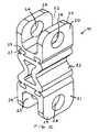
- FIG. 3is a simplified perspective illustration of an elastomeric spinal prosthesis, constructed and operative in accordance with yet another embodiment of the present invention, adapted for attachment to a posterior portion of the spine and to other vertebral structure, e.g., a facet or pedicle of the same vertebra;
- FIG. 4is a perspective view of a superior attachment member of the prosthesis shown in FIG. 3 ;
- FIG. 5is a perspective view of an inferior attachment member of the prosthesis shown in FIG. 3 ;
- FIG. 6is a perspective view of an elastomeric member of the prosthesis shown in FIG. 3 ;
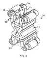
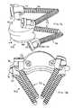
- FIGS. 7A and 7Bare simplified pictorial illustrations, from two different perspective views, of an elastomeric spinal prosthesis, constructed and operative in accordance with still another embodiment of the present invention.
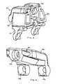
- FIGS. 8A and 8Bare simplified sectional illustrations, respectively along front and side facing planes, of the elastomeric spinal prosthesis shown in FIGS. 7A and 7B ;
- FIGS. 8C and 8Dare simplified sectional illustrations of an alternative construction of a flexure assembly of the elastomeric spinal prosthesis of FIGS. 8A and 8B .
- FIGS. 1A and 1Billustrate a structure of a human spine, in particular the lumbar vertebrae.
- FIGS. 1A and 1Billustrate the fourth and fifth lumbar vertebrae L4 and L5, respectively, in a lateral view (while in anatomic association) and in a superior view (separately).
- the lumbar vertebrae(of which there are a total of five) are in the lower back, also called the “small of the back.”
- each vertebraincludes a vertebral body 110 , which is the anterior, massive part of bone that gives strength to the vertebral column and supports body weight.
- a vertebral arch 112is posterior to the vertebral body 110 and is formed by right and left pedicles 114 and lamina 116 .
- the pedicles 114are short, stout processes that join the vertebral arch 112 to the vertebral body 110 .
- the pedicles 114project posteriorly to meet two broad flat plates of bone, called the lamina 116 .
- a spinous process 118 and two transverse processes 120project from the vertebral arch 112 and afford attachments for muscles, thus forming levers that help the muscles move the vertebrae.
- Two superior articular processes 122project superiorly from the vertebral arch 112 and two inferior articular processes 124 project inferiorly from the vertebral arch 112 .
- the superior articular processes 122 of a vertebraare located opposite corresponding inferior articular processes 124 of an adjacent vertebra.
- inferior articular processes 124are located opposite corresponding superior articular processes 122 of an adjacent vertebra.
- a vertebra's superior articular processes 122 with the inferior articular processes 124 of an adjacent vertebraform a joint, called a zygapophysial joint, or in short hand, a facet joint or facet 126 .
- Facet joints 126 found between adjacent superior articular processes 122 and inferior articular processes 124 along the spinal columnpermit gliding movement between the vertebrae L4 and L5.
- FIG. 1Cillustrates a spinal prosthesis 10 , constructed and operative in accordance with an embodiment of the present invention.
- Prosthesis 10may include an upper (superior) vertebral attachment member 20 attachable to one of the spinous processes 118 (not shown in FIG. 1C ), and a lower (inferior) vertebral attachment member 21 attachable to an adjacent spinous process 118 .
- Attachment members 20 and 21may be rigid or non-rigid, formed of materials including, but not limited to, a biocompatible material such as a metal, e.g., stainless steel, titanium or titanium alloy, cobalt chromium alloys, plastics or other hard, rigid materials or any combination of the above.
- An elastomeric member 22(also referred to as a flexure assembly) is placed between and may be integrally formed with or attached to upper and lower vertebral attachment members 20 and 21 .
- Elastomeric member 22may be made from a compliant material including, but not limited to, polyurethane containing materials, silicone containing materials, polyethylene based elastomers, hydrogels, and polypropylene containing materials.
- Elastomeric member 22may flex in any direction, which may help reduce tension between the attachment members 20 and 21 during movement of the spine.
- the flexure of elastomeric member 22permits the attachment members 20 and 21 to move relative to one another. This may help install the prosthesis in the body by overcoming misalignments between the parts of the prosthesis and the mounting holes in the body.
- any material or body structure such as ligamentsmay be removed or moved to the side temporarily in order to expose adjacent spinous processes.
- a laminactomy(cutting into the lamina 116 and removing at least a portion thereof) may be performed through a posterior incision.
- the attachment members 20 and 21may be attached to the exposed spinous processes 118 of the adjacent vertebrae.
- upper and lower vertebral attachment members 20 and 21are formed with mounting holes 24 adapted for a mechanical fastener (not shown) to pass through and into the spinous processes 118 .
- a mechanical fastener(not shown)
- any fastener or fastenerssuch as but not limited to, screws, bolts, rivets, nails, tacks and nuts may pass through holes 24 to firmly attach attachment members 20 and 21 to the spinous process 118 .
- the vertebral attachment members 20 and 21may have sidewalls 25 separated by a gap 23 (forming a U-shape).
- the spinous process 118 or any posterior portion of the spine, for example,may be received snugly (or loosely) in gap 23 prior to fastening with the mechanical fastener.
- a hole, or holes,may be drilled into or right through the spinous process 118 at a place opposite holes 24 in order to use the mechanical fasteners to firmly attach the attachment members 20 and 21 to the spinous processes 118 .
- elastomeric member 22may be attached to or integrally formed with upper and lower vertebral attachment members 20 and 21 by means of a tenon-and-mortise joint.
- the tenon-and-mortise jointmay comprise tenons 27 (protrusions) that mate with mortises (grooves) 29 .
- the inventionis not limited to this type of joint or connection, and other types of joints, connections, fastenings, adhesive bonding and the like may also be used.
- FIG. 2illustrates a spinal prosthesis 30 having upper and lower vertebral attachment members 32 and 34 that can be attached to a spinous process 118 without having to drill into or through the spinous process.
- a smaller incision to install the prosthesis 30may be used than to install the prosthesis 10 .
- This embodimentmay include upper and lower vertebral attachment members 32 and 34 that have one or more pairs of opposing resilient pawls 36 mounted on a base 38 and adapted for gripping the spinous process 118 .
- the pawls 36apply a spring force to tightly grip the spinous process 118 .
- the attachment membersmay thus be pushed into place and tightly “snap on” the spinous process 118 . (The spinous process 118 is received in gap 23 as before.)
- the prosthesismay be attached to the spinous process 118 alone.
- the attachment membersmay be additionally or alternatively attached to other parts of the vertebra, such as but not limited to parts of the facet 126 and/or to the pedicles 114 or any posterior portion of the spine, not just the spinous process 118 .
- Other embodiments that attach to the pedicles 114are described further hereinbelow.
- FIG. 3illustrates an elastomeric spinal prosthesis 39 , constructed and operative in accordance with yet another embodiment of the present invention.
- Prosthesis 39may be attached, for example, to the spinous process 118 and to other vertebral structure, e.g., a facet 126 or pedicle 114 or any posterior portion of the spine (see FIGS. 1A and 1B ; not shown in FIG. 3 ).
- Prosthesis 39may include an upper vertebral attachment member 40 attachable to the spinous process 118 , facet 126 and/or pedicle 114 , and a lower vertebral attachment member 41 attachable to another portion of the spine (not shown), such as an adjacent spinous process 118 , facet 126 and/or pedicle 114 .
- Attachment members 40 and 41may be rigid or non-rigid, as above.
- One or more elastomeric members 42may be placed between and may be integrally formed with or attached to upper and lower vertebral attachment members 40 and 41 .
- Elastomeric member 42shown clearly in FIG. 6 , may be made from a compliant material as above.
- upper and lower vertebral attachment members 40 and 41may be formed with one or more mounting holes adapted for a mechanical fastener (not shown) to pass through and into the portion of the spine.
- a mechanical fastenernot shown
- any fastener or fastenerssuch as but not limited to, screws, bolts, rivets, nails, tacks and nuts may pass through the mounting holes to firmly attach attachment members 40 and 41 to the spinous process 118 .
- FIGS. 4 and 5are posterior perspective views of non-limiting examples of upper and lower attachment members 40 and 41 , respectively, as shown in FIG. 3 .
- a mounting hole 44is formed for attaching attachment member 40 to the posterior of one of the spinous processes 118 , for example.
- Another mounting hole 46 in member 40may be for fixation to the right facet 126 of the same vertebra and yet another mounting hole 48 may be for fixation to the left facet 126 of the same vertebra.
- the three-point fixation or attachmentmay provide a stable and more secure attachment of member 40 to the vertebra posteriorly with a minimum amount of invasiveness.
- elastomeric membermay be attached to or integrally formed with upper and lower vertebral attachment members 40 and 41 by means of a tenon-and-mortise joint.
- the tenon-and-mortise jointmay comprise tenons 47 (protrusions) that mate with mortises (grooves) 49 .
- the inventionis not limited to this type of joint or connection, and other types of joints, connections, fastenings, adhesive bonding and the like may also be used.
- the mounting holesmay be placed and oriented in a multitude of manners.
- the mounting holes 24do not pass through a plane that intersects elastomeric member 22 .
- the mounting holes 24are generally transverse to a longitudinal axis of elastomeric member 22 .
- the mounting hole 44passes through a plane that intersects elastomeric member 42 .
- the mounting holes 44 , 46 and 48are generally parallel to the longitudinal axis of elastomeric member 42 .
- Other arrangementsare also within the scope of the invention.
- FIGS. 7A , 7 B, 8 A and 8 Billustrate an elastomeric spinal prosthesis 50 , constructed and operative in accordance with still another embodiment of the present invention.
- Prosthesis 50may be attached, for example, to the spinous process 118 and pedicles 114 (see FIGS. 1A and 1B ; not shown in FIGS. 7A , 7 B, 8 A and 8 B).
- Prosthesis 50may include an upper (superior) vertebral attachment member 52 and a lower (inferior) vertebral attachment member 54 .
- the attachment members 52 and 54may be attached to adjacent spinous processes 118 , but as is described further hereinbelow, the prosthesis 50 may be attached to pedicles without having to attach the attachment members 52 and 54 to the spinous processes 118 .
- Attachment members 52 and 54may be rigid or non-rigid, formed of materials including, but not limited to, a biocompatible material such as a metal, e.g., stainless steel, titanium or titanium alloy, cobalt chromium alloys, plastics or other hard, rigid materials or any combination of the above.
- a flexure assembly 56comprising one or more flexing members (described below), may be placed between and may be integrally formed with or attached to upper and lower vertebral attachment members 52 and 54 .
- Flexure assembly 56may be attached to upper and lower vertebral attachment members 52 and 54 by means of locking members 58 .
- Locking members 58may include plate-like elements 59 secured to upper and lower vertebral attachment members 52 and 54 with mechanical fasteners 60 , such as but not limited to, screws.
- Locking members 58may further include lugs 61 extending generally perpendicularly from plate-like elements 59 , around which stoppers 62 are securedly engaged. Four such stoppers 62 are shown in the illustrated embodiment, however, the invention may be carried out with any number of such stoppers.
- a boot 64may be placed at least partially or fully around inner portions of the attachment members 52 and 54 , e.g., at least partially or fully around the locking members 58 and stoppers 62 .
- the boot 64may have any suitable shape or size, such as but not limited to, a ring, a stocking, an ellipsoid and other shapes.
- the boot 64is sandwiched between upper and lower vertebral attachment members 52 and 54 , and connected to locking members 58 , such as but not necessarily, by means of inner ridges 65 of boot 64 fixedly engaging grooves 66 formed in plate-like elements 59 (as seen best in FIG. 8B ).
- flexure assembly 56comprises stoppers 62 and boot 64 .
- the flexure assembly 56may be constructed of a compliant, elastomeric material including, but not limited to, polyurethane containing materials, silicone containing materials, polyethylene based elastomers, hydrogels, and polypropylene containing materials.
- the flexure assembly 56may be constructed of rigid materials, such as stainless steel, for example.
- boot 64is made of a compliant material, such as but not limited to, an elastomer (e.g., polyurethane) or cloth (woven or non-woven synthetic or natural fibers).
- the flexure assembly 56permits flexure of prosthesis 50 about two mutually orthogonal axes 67 and 68 , as well as other directions for omnidirectional flexure in any degree of freedom.
- prosthesis 50can resiliently rotate about axis 67 in the direction of arrows 69 .
- prosthesis 50can resiliently rotate about axis 68 in the direction of arrows 70 .
- the stoppers 62(as well as boot 64 to some extent) may limit the flexure of flexure assembly 56 and thus limit the relative movement of the attachment members 52 and 54 with respect to one another.
- pedicle screws 72( FIGS. 7A and 7B ) for installing prosthesis 50 into the pedicles 114 .
- the pedicle screws 72may comprise, without limitation, polyaxial pedicle screws, e.g., made of titanium or titanium alloy, commercially available in many sizes and shapes from many manufacturers. It is noted that titanium is highly resistant to corrosion and fatigue, and is MRI compatible.
- the pedicle screw 72may have a threaded shank 74 and a mobile, swivel head 75 , whose ability to swivel may help avoid vertebral stress.
- the swivel heads 75may be rotatably attached to rounded prongs 76 jutting from upper and lower vertebral attachment members 52 and 54 , by means of lock nuts 77 that mate with heads 75 .
- a laminactomymay be performed, thereby creating a gap between the spinous processes 118 , as mentioned hereinabove.
- the pedicle screws 72may be screwed into the pedicles 114 .
- the prosthesis 50may be inserted in the gap between the spinous processes 118 , with the rounded prongs 76 aligned with the heads 75 of the pedicle screws 72 .
- the lock nuts 77may then secure the prosthesis 50 to the pedicle screws 72 .
- the prosthesis 50may thus be attached to the pedicles without having to attach the attachment members 52 and 54 to the spinous processes 118 .
- attachment members 52 and 54may also be attached to adjacent spinous processes 118 or other spinal structure by any convenient method.
- the outer surfaces of attachment members 52 and 54may be coated with a material, such as but not limited to, Hydroxy-Appatite (H/A), which encourages bone growth into the outer surfaces thereof.
- H/AHydroxy-Appatite
- FIGS. 8C and 8Dillustrate an alternative construction of the flexure assembly 56 of the elastomeric spinal prosthesis 50 .
- flexure assembly 56may be constructed may include a two-part articulating assembly, constructed of a first joint member 101 , which may have a convex outer contour 102 with a truncated face 103 .
- a semi-circular cutout 104may be gouged out of the convex outer contour 102 .
- a plate 105may secure the first joint member 101 to the lower attachment member 54 , such as with screws (not shown) that pass through mounting holes 106 .
- the other part of the two-part articulating assembly of flexure assembly 56may include a second joint member 107 , which may have a concave outer contour 108 that corresponds to and glides over the convex outer contour of the first joint member 101 .
- a plate 109may secure the second joint member 107 to the upper attachment member 52 , such as with screws (not shown) that pass through mounting holes 110 .
- a stopper 111may be provided, either as part of the second joint member 107 or as a separate part attached to the upper attachment member 52 . The stopper 111 protrudes into the semi-circular cutout 104 .
- this version of the flexure assembly 56 shown in FIGS. 8C and 8Dpermits flexure of prosthesis 50 about two mutually orthogonal axes 67 and 68 as well as other directions for omnidirectional flexure in any degree of freedom.
- prosthesis 50can resiliently rotate about axis 67 in the direction of arrows 69 .
- prosthesis 50can resiliently rotate about axis 68 in the direction of arrows 70 .
- the stopper 111may limit the flexure of flexure assembly 56 and thus limit the relative movement of the attachment members 52 and 54 with respect to one another.
- each of the spinal prostheses described hereinaboveinclude a unitary body with at least three attachment points attachable to spinal structure.
- unitary bodyit is meant that the spinal prosthesis may be attached to the spinal structure as one pre-assembled, contiguous assembly. The surgeon can simply hold the entire unitary body in place during attachment to the spinal structure. This is in contrast to known prostheses that must be attached to the spinal structure as at least two separate parts, which may or may not articulate with one another. With those prostheses, the surgeon must attach each part separately to some spinal structure and merely “hope” that the parts fit together properly after installment.
- the unitary construction of the present inventioneliminates this problem and greatly facilitates installation of the prosthesis.
- attachment of attachment memberswas to either the spinous process alone or to the spinous process and to the facet or to the spinous process and to pedicle of the particular vertebra
- any combination of the above embodimentswill bring about similar results (such as stabilization of the spine, relief of pain, implantation of the prosthesis, etc.) and the above examples are just examples of attachment sites and not in any way meant to be limiting.
- a superior attachment membermay be attached to a spinous process alone and the prosthesis's inferior attachment member may be attached to the adjacent vertebra's spinous process and to its pedicle or facet or even a combination of both.
- the prosthesis of this inventionmay be used in conjunction with an implant that is anterior to the spinal cord such as a total disc replacement.
Landscapes
- Health & Medical Sciences (AREA)
- Orthopedic Medicine & Surgery (AREA)
- Life Sciences & Earth Sciences (AREA)
- Neurology (AREA)
- Surgery (AREA)
- Heart & Thoracic Surgery (AREA)
- Engineering & Computer Science (AREA)
- Biomedical Technology (AREA)
- Nuclear Medicine, Radiotherapy & Molecular Imaging (AREA)
- Medical Informatics (AREA)
- Molecular Biology (AREA)
- Animal Behavior & Ethology (AREA)
- General Health & Medical Sciences (AREA)
- Public Health (AREA)
- Veterinary Medicine (AREA)
- Prostheses (AREA)
- Surgical Instruments (AREA)
- Steroid Compounds (AREA)
Abstract
Description
Claims (6)
Priority Applications (1)
| Application Number | Priority Date | Filing Date | Title |
|---|---|---|---|
| US11/692,200US8012176B2 (en) | 2003-11-07 | 2007-03-28 | Spinal prostheses |
Applications Claiming Priority (4)
| Application Number | Priority Date | Filing Date | Title |
|---|---|---|---|
| US51788803P | 2003-11-07 | 2003-11-07 | |
| US10/750,860US7011685B2 (en) | 2003-11-07 | 2004-01-05 | Spinal prostheses |
| US11/369,816US7537613B2 (en) | 2003-11-07 | 2006-03-08 | Spinal prostheses |
| US11/692,200US8012176B2 (en) | 2003-11-07 | 2007-03-28 | Spinal prostheses |
Related Parent Applications (1)
| Application Number | Title | Priority Date | Filing Date |
|---|---|---|---|
| US11/369,816ContinuationUS7537613B2 (en) | 2003-11-07 | 2006-03-08 | Spinal prostheses |
Publications (2)
| Publication Number | Publication Date |
|---|---|
| US20070191948A1 US20070191948A1 (en) | 2007-08-16 |
| US8012176B2true US8012176B2 (en) | 2011-09-06 |
Family
ID=34572972
Family Applications (13)
| Application Number | Title | Priority Date | Filing Date |
|---|---|---|---|
| US10/750,860Expired - LifetimeUS7011685B2 (en) | 2003-11-07 | 2004-01-05 | Spinal prostheses |
| US11/369,816Expired - LifetimeUS7537613B2 (en) | 2003-11-07 | 2006-03-08 | Spinal prostheses |
| US11/692,197Active2026-05-18US7833272B2 (en) | 2003-11-07 | 2007-03-28 | Spinal prostheses |
| US11/692,203Active2026-05-16US7811324B2 (en) | 2003-11-07 | 2007-03-28 | Spinal prostheses |
| US11/692,200Expired - LifetimeUS8012176B2 (en) | 2003-11-07 | 2007-03-28 | Spinal prostheses |
| US11/692,204Active - Reinstated2026-06-02US8262699B2 (en) | 2003-11-07 | 2007-03-28 | Spinal prostheses |
| US11/692,202Active2026-05-09US7811323B2 (en) | 2003-11-07 | 2007-03-28 | Spinal prostheses |
| US11/692,198Active2026-04-19US7811308B2 (en) | 2003-11-07 | 2007-03-28 | Spinal prostheses |
| US11/692,201Active2026-05-09US7811322B2 (en) | 2003-11-07 | 2007-03-28 | Spinal prostheses |
| US11/692,199Active2026-05-03US7811330B2 (en) | 2003-11-07 | 2007-03-28 | Spinal prostheses |
| US11/833,248Active2025-11-14US7846209B2 (en) | 2003-11-07 | 2007-08-03 | Spinal prostheses |
| US11/833,246Active2025-11-06US7842090B2 (en) | 2003-11-07 | 2007-08-03 | Spinal prostheses |
| US11/858,277AbandonedUS20080009948A1 (en) | 2003-11-07 | 2007-09-20 | Spinal prostheses |
Family Applications Before (4)
| Application Number | Title | Priority Date | Filing Date |
|---|---|---|---|
| US10/750,860Expired - LifetimeUS7011685B2 (en) | 2003-11-07 | 2004-01-05 | Spinal prostheses |
| US11/369,816Expired - LifetimeUS7537613B2 (en) | 2003-11-07 | 2006-03-08 | Spinal prostheses |
| US11/692,197Active2026-05-18US7833272B2 (en) | 2003-11-07 | 2007-03-28 | Spinal prostheses |
| US11/692,203Active2026-05-16US7811324B2 (en) | 2003-11-07 | 2007-03-28 | Spinal prostheses |
Family Applications After (8)
| Application Number | Title | Priority Date | Filing Date |
|---|---|---|---|
| US11/692,204Active - Reinstated2026-06-02US8262699B2 (en) | 2003-11-07 | 2007-03-28 | Spinal prostheses |
| US11/692,202Active2026-05-09US7811323B2 (en) | 2003-11-07 | 2007-03-28 | Spinal prostheses |
| US11/692,198Active2026-04-19US7811308B2 (en) | 2003-11-07 | 2007-03-28 | Spinal prostheses |
| US11/692,201Active2026-05-09US7811322B2 (en) | 2003-11-07 | 2007-03-28 | Spinal prostheses |
| US11/692,199Active2026-05-03US7811330B2 (en) | 2003-11-07 | 2007-03-28 | Spinal prostheses |
| US11/833,248Active2025-11-14US7846209B2 (en) | 2003-11-07 | 2007-08-03 | Spinal prostheses |
| US11/833,246Active2025-11-06US7842090B2 (en) | 2003-11-07 | 2007-08-03 | Spinal prostheses |
| US11/858,277AbandonedUS20080009948A1 (en) | 2003-11-07 | 2007-09-20 | Spinal prostheses |
Country Status (6)
| Country | Link |
|---|---|
| US (13) | US7011685B2 (en) |
| EP (1) | EP1578314B1 (en) |
| AT (1) | ATE363250T1 (en) |
| DE (1) | DE602004006709T2 (en) |
| ES (1) | ES2287686T3 (en) |
| WO (1) | WO2005044152A1 (en) |
Cited By (6)
| Publication number | Priority date | Publication date | Assignee | Title |
|---|---|---|---|---|
| US8864828B2 (en) | 2004-10-20 | 2014-10-21 | Vertiflex, Inc. | Interspinous spacer |
| US8900271B2 (en) | 2004-10-20 | 2014-12-02 | The Board Of Trustees Of The Leland Stanford Junior University | Systems and methods for posterior dynamic stabilization of the spine |
| US9039742B2 (en) | 2004-10-20 | 2015-05-26 | The Board Of Trustees Of The Leland Stanford Junior University | Systems and methods for posterior dynamic stabilization of the spine |
| US9119680B2 (en) | 2004-10-20 | 2015-09-01 | Vertiflex, Inc. | Interspinous spacer |
| US9155570B2 (en) | 2004-10-20 | 2015-10-13 | Vertiflex, Inc. | Interspinous spacer |
| US10398478B2 (en) | 2015-07-31 | 2019-09-03 | Paradigm Spine, Llc | Interspinous stabilization and fusion device |
Families Citing this family (288)
| Publication number | Priority date | Publication date | Assignee | Title |
|---|---|---|---|---|
| US20080039859A1 (en)* | 1997-01-02 | 2008-02-14 | Zucherman James F | Spine distraction implant and method |
| US8128661B2 (en)* | 1997-01-02 | 2012-03-06 | Kyphon Sarl | Interspinous process distraction system and method with positionable wing and method |
| US20080086212A1 (en)* | 1997-01-02 | 2008-04-10 | St. Francis Medical Technologies, Inc. | Spine distraction implant |
| US6695842B2 (en)* | 1997-10-27 | 2004-02-24 | St. Francis Medical Technologies, Inc. | Interspinous process distraction system and method with positionable wing and method |
| US7201751B2 (en) | 1997-01-02 | 2007-04-10 | St. Francis Medical Technologies, Inc. | Supplemental spine fixation device |
| US7959652B2 (en)* | 2005-04-18 | 2011-06-14 | Kyphon Sarl | Interspinous process implant having deployable wings and method of implantation |
| US6068630A (en)* | 1997-01-02 | 2000-05-30 | St. Francis Medical Technologies, Inc. | Spine distraction implant |
| US7306628B2 (en)* | 2002-10-29 | 2007-12-11 | St. Francis Medical Technologies | Interspinous process apparatus and method with a selectably expandable spacer |
| US6811567B2 (en)* | 1999-10-22 | 2004-11-02 | Archus Orthopedics Inc. | Facet arthroplasty devices and methods |
| US7674293B2 (en)* | 2004-04-22 | 2010-03-09 | Facet Solutions, Inc. | Crossbar spinal prosthesis having a modular design and related implantation methods |
| US7691145B2 (en) | 1999-10-22 | 2010-04-06 | Facet Solutions, Inc. | Prostheses, systems and methods for replacement of natural facet joints with artificial facet joint surfaces |
| US8187303B2 (en)* | 2004-04-22 | 2012-05-29 | Gmedelaware 2 Llc | Anti-rotation fixation element for spinal prostheses |
| ATE285207T1 (en) | 1999-10-22 | 2005-01-15 | Archus Orthopedics Inc | FACET ARTHROPLASTY DEVICES |
| US6579319B2 (en) | 2000-11-29 | 2003-06-17 | Medicinelodge, Inc. | Facet joint replacement |
| US20050080486A1 (en) | 2000-11-29 | 2005-04-14 | Fallin T. Wade | Facet joint replacement |
| US6565605B2 (en) | 2000-12-13 | 2003-05-20 | Medicinelodge, Inc. | Multiple facet joint replacement |
| US6419703B1 (en) | 2001-03-01 | 2002-07-16 | T. Wade Fallin | Prosthesis for the replacement of a posterior element of a vertebra |
| US7090698B2 (en) | 2001-03-02 | 2006-08-15 | Facet Solutions | Method and apparatus for spine joint replacement |
| FR2828398B1 (en)* | 2001-08-08 | 2003-09-19 | Jean Taylor | VERTEBRA STABILIZATION ASSEMBLY |
| US7241272B2 (en) | 2001-11-13 | 2007-07-10 | Baxter International Inc. | Method and composition for removing uremic toxins in dialysis processes |
| DE60336724D1 (en) | 2002-07-19 | 2011-05-26 | Baxter Healthcare Sa | SYSTEM FOR PERITONEAL DIALYSIS |
| AU2003265597A1 (en)* | 2002-08-23 | 2004-03-11 | Paul C. Mcafee | Metal-backed uhmpe rod sleeve system preserving spinal motion |
| FR2844179B1 (en)* | 2002-09-10 | 2004-12-03 | Jean Taylor | POSTERIOR VERTEBRAL SUPPORT KIT |
| US20060264939A1 (en)* | 2003-05-22 | 2006-11-23 | St. Francis Medical Technologies, Inc. | Interspinous process implant with slide-in distraction piece and method of implantation |
| US8070778B2 (en)* | 2003-05-22 | 2011-12-06 | Kyphon Sarl | Interspinous process implant with slide-in distraction piece and method of implantation |
| US7931674B2 (en)* | 2005-03-21 | 2011-04-26 | Kyphon Sarl | Interspinous process implant having deployable wing and method of implantation |
| US8048117B2 (en) | 2003-05-22 | 2011-11-01 | Kyphon Sarl | Interspinous process implant and method of implantation |
| US20080021468A1 (en)* | 2002-10-29 | 2008-01-24 | Zucherman James F | Interspinous process implants and methods of use |
| US7549999B2 (en)* | 2003-05-22 | 2009-06-23 | Kyphon Sarl | Interspinous process distraction implant and method of implantation |
| US8147548B2 (en) | 2005-03-21 | 2012-04-03 | Kyphon Sarl | Interspinous process implant having a thread-shaped wing and method of implantation |
| US7608104B2 (en)* | 2003-05-14 | 2009-10-27 | Archus Orthopedics, Inc. | Prostheses, tools and methods for replacement of natural facet joints with artifical facet joint surfaces |
| US7074238B2 (en) | 2003-07-08 | 2006-07-11 | Archus Orthopedics, Inc. | Prostheses, tools and methods for replacement of natural facet joints with artificial facet joint surfaces |
| FR2858546B1 (en) | 2003-08-04 | 2006-04-28 | Spine Next Sa | INTERVERTEBRAL DISC PROSTHESIS |
| US7799082B2 (en) | 2003-08-05 | 2010-09-21 | Flexuspine, Inc. | Artificial functional spinal unit system and method for use |
| US7753958B2 (en) | 2003-08-05 | 2010-07-13 | Gordon Charles R | Expandable intervertebral implant |
| US7909869B2 (en) | 2003-08-05 | 2011-03-22 | Flexuspine, Inc. | Artificial spinal unit assemblies |
| DE602004006709T2 (en)* | 2003-11-07 | 2008-02-07 | Impliant Ltd. | SPINE GRAFT |
| US7588590B2 (en) | 2003-12-10 | 2009-09-15 | Facet Solutions, Inc | Spinal facet implant with spherical implant apposition surface and bone bed and methods of use |
| US20050131406A1 (en) | 2003-12-15 | 2005-06-16 | Archus Orthopedics, Inc. | Polyaxial adjustment of facet joint prostheses |
| US8333789B2 (en) | 2007-01-10 | 2012-12-18 | Gmedelaware 2 Llc | Facet joint replacement |
| US7993373B2 (en) | 2005-02-22 | 2011-08-09 | Hoy Robert W | Polyaxial orthopedic fastening apparatus |
| US8562649B2 (en) | 2004-02-17 | 2013-10-22 | Gmedelaware 2 Llc | System and method for multiple level facet joint arthroplasty and fusion |
| US7763073B2 (en)* | 2004-03-09 | 2010-07-27 | Depuy Spine, Inc. | Posterior process dynamic spacer |
| US7717939B2 (en) | 2004-03-31 | 2010-05-18 | Depuy Spine, Inc. | Rod attachment for head to head cross connector |
| US7645294B2 (en) | 2004-03-31 | 2010-01-12 | Depuy Spine, Inc. | Head-to-head connector spinal fixation system |
| US7282065B2 (en)* | 2004-04-09 | 2007-10-16 | X-Spine Systems, Inc. | Disk augmentation system and method |
| US7406775B2 (en)* | 2004-04-22 | 2008-08-05 | Archus Orthopedics, Inc. | Implantable orthopedic device component selection instrument and methods |
| US7051451B2 (en)* | 2004-04-22 | 2006-05-30 | Archus Orthopedics, Inc. | Facet joint prosthesis measurement and implant tools |
| WO2006055186A2 (en) | 2004-10-25 | 2006-05-26 | Archus Orthopedics, Inc. | Spinal prosthesis having a modular design |
| US7914556B2 (en) | 2005-03-02 | 2011-03-29 | Gmedelaware 2 Llc | Arthroplasty revision system and method |
| US7585316B2 (en)* | 2004-05-21 | 2009-09-08 | Warsaw Orthopedic, Inc. | Interspinous spacer |
| US8764801B2 (en) | 2005-03-28 | 2014-07-01 | Gmedelaware 2 Llc | Facet joint implant crosslinking apparatus and method |
| US7507242B2 (en) | 2004-06-02 | 2009-03-24 | Facet Solutions | Surgical measurement and resection framework |
| US7854752B2 (en)* | 2004-08-09 | 2010-12-21 | Theken Spine, Llc | System and method for dynamic skeletal stabilization |
| CA2574277A1 (en)* | 2004-08-09 | 2006-02-23 | Innovative Spinal Technologies, Inc. | System and method for dynamic skeletal stabilization |
| DE502004008055D1 (en)* | 2004-08-13 | 2008-10-23 | Synthes Gmbh | INTERSPINAL IMPLANT |
| AU2005277363A1 (en) | 2004-08-18 | 2006-03-02 | Fsi Acquisition Sub, Llc | Adjacent level facet arthroplasty devices, spine stabilization systems, and methods |
| US7717938B2 (en)* | 2004-08-27 | 2010-05-18 | Depuy Spine, Inc. | Dual rod cross connectors and inserter tools |
| US7887566B2 (en)* | 2004-09-16 | 2011-02-15 | Hynes Richard A | Intervertebral support device with bias adjustment and related methods |
| US8092496B2 (en) | 2004-09-30 | 2012-01-10 | Depuy Spine, Inc. | Methods and devices for posterior stabilization |
| US7766940B2 (en) | 2004-12-30 | 2010-08-03 | Depuy Spine, Inc. | Posterior stabilization system |
| US20060084976A1 (en)* | 2004-09-30 | 2006-04-20 | Depuy Spine, Inc. | Posterior stabilization systems and methods |
| US7896906B2 (en)* | 2004-12-30 | 2011-03-01 | Depuy Spine, Inc. | Artificial facet joint |
| US7763074B2 (en) | 2004-10-20 | 2010-07-27 | The Board Of Trustees Of The Leland Stanford Junior University | Systems and methods for posterior dynamic stabilization of the spine |
| US8162985B2 (en)* | 2004-10-20 | 2012-04-24 | The Board Of Trustees Of The Leland Stanford Junior University | Systems and methods for posterior dynamic stabilization of the spine |
| US8277488B2 (en) | 2004-10-20 | 2012-10-02 | Vertiflex, Inc. | Interspinous spacer |
| US8613747B2 (en) | 2004-10-20 | 2013-12-24 | Vertiflex, Inc. | Spacer insertion instrument |
| US8945183B2 (en) | 2004-10-20 | 2015-02-03 | Vertiflex, Inc. | Interspinous process spacer instrument system with deployment indicator |
| US7935134B2 (en) | 2004-10-20 | 2011-05-03 | Exactech, Inc. | Systems and methods for stabilization of bone structures |
| US9161783B2 (en) | 2004-10-20 | 2015-10-20 | Vertiflex, Inc. | Interspinous spacer |
| US20070239159A1 (en)* | 2005-07-22 | 2007-10-11 | Vertiflex, Inc. | Systems and methods for stabilization of bone structures |
| US8425559B2 (en) | 2004-10-20 | 2013-04-23 | Vertiflex, Inc. | Systems and methods for posterior dynamic stabilization of the spine |
| US8025680B2 (en)* | 2004-10-20 | 2011-09-27 | Exactech, Inc. | Systems and methods for posterior dynamic stabilization of the spine |
| US8128662B2 (en) | 2004-10-20 | 2012-03-06 | Vertiflex, Inc. | Minimally invasive tooling for delivery of interspinous spacer |
| US9023084B2 (en) | 2004-10-20 | 2015-05-05 | The Board Of Trustees Of The Leland Stanford Junior University | Systems and methods for stabilizing the motion or adjusting the position of the spine |
| US8123807B2 (en) | 2004-10-20 | 2012-02-28 | Vertiflex, Inc. | Systems and methods for posterior dynamic stabilization of the spine |
| US8409282B2 (en) | 2004-10-20 | 2013-04-02 | Vertiflex, Inc. | Systems and methods for posterior dynamic stabilization of the spine |
| US8267969B2 (en) | 2004-10-20 | 2012-09-18 | Exactech, Inc. | Screw systems and methods for use in stabilization of bone structures |
| US8226690B2 (en) | 2005-07-22 | 2012-07-24 | The Board Of Trustees Of The Leland Stanford Junior University | Systems and methods for stabilization of bone structures |
| US8317864B2 (en) | 2004-10-20 | 2012-11-27 | The Board Of Trustees Of The Leland Stanford Junior University | Systems and methods for posterior dynamic stabilization of the spine |
| US8123782B2 (en) | 2004-10-20 | 2012-02-28 | Vertiflex, Inc. | Interspinous spacer |
| US8012207B2 (en) | 2004-10-20 | 2011-09-06 | Vertiflex, Inc. | Systems and methods for posterior dynamic stabilization of the spine |
| US9055981B2 (en) | 2004-10-25 | 2015-06-16 | Lanx, Inc. | Spinal implants and methods |
| US8241330B2 (en) | 2007-01-11 | 2012-08-14 | Lanx, Inc. | Spinous process implants and associated methods |
| EP2219538B1 (en) | 2004-12-06 | 2022-07-06 | Vertiflex, Inc. | Spacer insertion instrument |
| US8597331B2 (en)* | 2004-12-10 | 2013-12-03 | Life Spine, Inc. | Prosthetic spinous process and method |
| US8172877B2 (en)* | 2004-12-13 | 2012-05-08 | Kyphon Sarl | Inter-cervical facet implant with surface enhancements |
| US7655044B2 (en)* | 2004-12-13 | 2010-02-02 | Depuy Spine, Inc. | Artificial facet joint device having a compression spring |
| US7491238B2 (en)* | 2004-12-23 | 2009-02-17 | Impliant Ltd. | Adjustable spinal prosthesis |
| US20060200156A1 (en)* | 2005-01-05 | 2006-09-07 | Jamal Taha | Spinal docking system, spinal docking device, and methods of spinal stabilization |
| US20060190081A1 (en)* | 2005-02-09 | 2006-08-24 | Gary Kraus | Facet stabilization schemes |
| US8096994B2 (en) | 2005-02-17 | 2012-01-17 | Kyphon Sarl | Percutaneous spinal implants and methods |
| US8034080B2 (en) | 2005-02-17 | 2011-10-11 | Kyphon Sarl | Percutaneous spinal implants and methods |
| US20060184248A1 (en)* | 2005-02-17 | 2006-08-17 | Edidin Avram A | Percutaneous spinal implants and methods |
| US8038698B2 (en)* | 2005-02-17 | 2011-10-18 | Kphon Sarl | Percutaneous spinal implants and methods |
| US8157841B2 (en)* | 2005-02-17 | 2012-04-17 | Kyphon Sarl | Percutaneous spinal implants and methods |
| US8029567B2 (en)* | 2005-02-17 | 2011-10-04 | Kyphon Sarl | Percutaneous spinal implants and methods |
| US20080039944A1 (en)* | 2005-02-17 | 2008-02-14 | Malandain Hugues F | Percutaneous Spinal Implants and Methods |
| US20080288078A1 (en)* | 2005-02-17 | 2008-11-20 | Kohm Andrew C | Percutaneous spinal implants and methods |
| US7988709B2 (en)* | 2005-02-17 | 2011-08-02 | Kyphon Sarl | Percutaneous spinal implants and methods |
| US8100943B2 (en) | 2005-02-17 | 2012-01-24 | Kyphon Sarl | Percutaneous spinal implants and methods |
| US8057513B2 (en) | 2005-02-17 | 2011-11-15 | Kyphon Sarl | Percutaneous spinal implants and methods |
| US20070055237A1 (en)* | 2005-02-17 | 2007-03-08 | Edidin Avram A | Percutaneous spinal implants and methods |
| US20070276493A1 (en)* | 2005-02-17 | 2007-11-29 | Malandain Hugues F | Percutaneous spinal implants and methods |
| US8007521B2 (en)* | 2005-02-17 | 2011-08-30 | Kyphon Sarl | Percutaneous spinal implants and methods |
| US8097018B2 (en)* | 2005-02-17 | 2012-01-17 | Kyphon Sarl | Percutaneous spinal implants and methods |
| US7998174B2 (en) | 2005-02-17 | 2011-08-16 | Kyphon Sarl | Percutaneous spinal implants and methods |
| US20070276372A1 (en)* | 2005-02-17 | 2007-11-29 | Malandain Hugues F | Percutaneous Spinal Implants and Methods |
| US7267690B2 (en) | 2005-03-09 | 2007-09-11 | Vertebral Technologies, Inc. | Interlocked modular disc nucleus prosthesis |
| US7722647B1 (en) | 2005-03-14 | 2010-05-25 | Facet Solutions, Inc. | Apparatus and method for posterior vertebral stabilization |
| US8496686B2 (en)* | 2005-03-22 | 2013-07-30 | Gmedelaware 2 Llc | Minimally invasive spine restoration systems, devices, methods and kits |
| US20060241757A1 (en)* | 2005-03-31 | 2006-10-26 | Sdgi Holdings, Inc. | Intervertebral prosthetic device for spinal stabilization and method of manufacturing same |
| US9675385B2 (en) | 2005-04-12 | 2017-06-13 | Nathan C. Moskowitz | Spinous process staple with interdigitating-interlocking hemi-spacers for adjacent spinous process separation and distraction |
| US8034079B2 (en)* | 2005-04-12 | 2011-10-11 | Warsaw Orthopedic, Inc. | Implants and methods for posterior dynamic stabilization of a spinal motion segment |
| CA2614898C (en)* | 2005-04-27 | 2014-04-22 | Trinity Orthopedics, Llc | Mono-planar pedilcle screw method, system, and kit |
| US7727233B2 (en)* | 2005-04-29 | 2010-06-01 | Warsaw Orthopedic, Inc. | Spinous process stabilization devices and methods |
| US20060276790A1 (en)* | 2005-06-02 | 2006-12-07 | Zimmer Spine, Inc. | Minimally invasive facet joint repair |
| US7951169B2 (en) | 2005-06-10 | 2011-05-31 | Depuy Spine, Inc. | Posterior dynamic stabilization cross connectors |
| US20070005064A1 (en)* | 2005-06-27 | 2007-01-04 | Sdgi Holdings | Intervertebral prosthetic device for spinal stabilization and method of implanting same |
| FR2887434B1 (en) | 2005-06-28 | 2008-03-28 | Jean Taylor | SURGICAL TREATMENT EQUIPMENT OF TWO VERTEBRATES |
| US8523865B2 (en) | 2005-07-22 | 2013-09-03 | Exactech, Inc. | Tissue splitter |
| US8163024B2 (en)* | 2005-09-14 | 2012-04-24 | Premia Spine Ltd. | Adjustable spinal prostheses |
| US8486145B2 (en)* | 2005-09-19 | 2013-07-16 | Premia Spine Ltd. | Flexure limiter for spinal prosthesis |
| BRPI0520561A2 (en)* | 2005-09-21 | 2010-03-23 | Sintea Biotech S P A | intervertebral stabilization device, medical kit for intervertebral stabilization, intervertebral stabilization method |
| US7879074B2 (en)* | 2005-09-27 | 2011-02-01 | Depuy Spine, Inc. | Posterior dynamic stabilization systems and methods |
| US8357181B2 (en)* | 2005-10-27 | 2013-01-22 | Warsaw Orthopedic, Inc. | Intervertebral prosthetic device for spinal stabilization and method of implanting same |
| US8430911B2 (en)* | 2005-12-14 | 2013-04-30 | Spinefrontier Inc | Spinous process fixation implant |
| US7695514B2 (en)* | 2005-12-29 | 2010-04-13 | Depuy Spine, Inc. | Facet joint and spinal ligament replacement |
| US20070173822A1 (en)* | 2006-01-13 | 2007-07-26 | Sdgi Holdings, Inc. | Use of a posterior dynamic stabilization system with an intradiscal device |
| US7815680B2 (en)* | 2006-01-13 | 2010-10-19 | Nabil L. Muhanna | Flexible vertebral implant |
| US8083795B2 (en)* | 2006-01-18 | 2011-12-27 | Warsaw Orthopedic, Inc. | Intervertebral prosthetic device for spinal stabilization and method of manufacturing same |
| US20070173823A1 (en) | 2006-01-18 | 2007-07-26 | Sdgi Holdings, Inc. | Intervertebral prosthetic device for spinal stabilization and method of implanting same |
| US7682376B2 (en)* | 2006-01-27 | 2010-03-23 | Warsaw Orthopedic, Inc. | Interspinous devices and methods of use |
| US20070191838A1 (en)* | 2006-01-27 | 2007-08-16 | Sdgi Holdings, Inc. | Interspinous devices and methods of use |
| US7691130B2 (en) | 2006-01-27 | 2010-04-06 | Warsaw Orthopedic, Inc. | Spinal implants including a sensor and methods of use |
| US8118869B2 (en)* | 2006-03-08 | 2012-02-21 | Flexuspine, Inc. | Dynamic interbody device |
| US8262698B2 (en)* | 2006-03-16 | 2012-09-11 | Warsaw Orthopedic, Inc. | Expandable device for insertion between anatomical structures and a procedure utilizing same |
| US8025681B2 (en)* | 2006-03-29 | 2011-09-27 | Theken Spine, Llc | Dynamic motion spinal stabilization system |
| FR2899788B1 (en)* | 2006-04-13 | 2008-07-04 | Jean Taylor | TREATMENT EQUIPMENT FOR VERTEBRATES, COMPRISING AN INTEREPINOUS IMPLANT |
| US20070270959A1 (en)* | 2006-04-18 | 2007-11-22 | Sdgi Holdings, Inc. | Arthroplasty device |
| US20070288012A1 (en)* | 2006-04-21 | 2007-12-13 | Dennis Colleran | Dynamic motion spinal stabilization system and device |
| US8118844B2 (en) | 2006-04-24 | 2012-02-21 | Warsaw Orthopedic, Inc. | Expandable device for insertion between anatomical structures and a procedure utilizing same |
| US20070270962A1 (en)* | 2006-04-26 | 2007-11-22 | Impliant Ltd. | Tools for spinal prostheses |
| US8048118B2 (en) | 2006-04-28 | 2011-11-01 | Warsaw Orthopedic, Inc. | Adjustable interspinous process brace |
| US20070270824A1 (en)* | 2006-04-28 | 2007-11-22 | Warsaw Orthopedic, Inc. | Interspinous process brace |
| DE102007018860B4 (en)* | 2006-04-28 | 2023-01-05 | Paradigm Spine L.L.C. | Instrument system for use with an interspinous implant |
| US8062337B2 (en)* | 2006-05-04 | 2011-11-22 | Warsaw Orthopedic, Inc. | Expandable device for insertion between anatomical structures and a procedure utilizing same |
| US8147517B2 (en)* | 2006-05-23 | 2012-04-03 | Warsaw Orthopedic, Inc. | Systems and methods for adjusting properties of a spinal implant |
| US20070276496A1 (en)* | 2006-05-23 | 2007-11-29 | Sdgi Holdings, Inc. | Surgical spacer with shape control |
| US8048120B1 (en)* | 2006-05-31 | 2011-11-01 | Medicine Lodge, Inc. | System and method for segmentally modular spinal plating |
| US20080058808A1 (en) | 2006-06-14 | 2008-03-06 | Spartek Medical, Inc. | Implant system and method to treat degenerative disorders of the spine |
| FR2902639B1 (en)* | 2006-06-26 | 2008-08-22 | Arca Medica Gmbh | IMPLANT INTENDED FOR THE STABILIZATION OF THE SACRED LOMBO REGION |
| AU2006345898A1 (en)* | 2006-07-03 | 2008-01-10 | Sami Khalife | Interspinous stabilization system |
| US8048119B2 (en)* | 2006-07-20 | 2011-11-01 | Warsaw Orthopedic, Inc. | Apparatus for insertion between anatomical structures and a procedure utilizing same |
| US20080039847A1 (en)* | 2006-08-09 | 2008-02-14 | Mark Piper | Implant and system for stabilization of the spine |
| US8702755B2 (en) | 2006-08-11 | 2014-04-22 | Gmedelaware 2 Llc | Angled washer polyaxial connection for dynamic spine prosthesis |
| US8906096B2 (en) | 2006-08-15 | 2014-12-09 | GMFDelaware 2 LLC | Spinal implant |
| US20080086115A1 (en)* | 2006-09-07 | 2008-04-10 | Warsaw Orthopedic, Inc. | Intercostal spacer device and method for use in correcting a spinal deformity |
| US8845726B2 (en) | 2006-10-18 | 2014-09-30 | Vertiflex, Inc. | Dilator |
| US8097019B2 (en) | 2006-10-24 | 2012-01-17 | Kyphon Sarl | Systems and methods for in situ assembly of an interspinous process distraction implant |
| US8096996B2 (en) | 2007-03-20 | 2012-01-17 | Exactech, Inc. | Rod reducer |
| FR2908035B1 (en)* | 2006-11-08 | 2009-05-01 | Jean Taylor | INTEREPINE IMPLANT |
| US8361117B2 (en) | 2006-11-08 | 2013-01-29 | Depuy Spine, Inc. | Spinal cross connectors |
| US20080114455A1 (en)* | 2006-11-15 | 2008-05-15 | Warsaw Orthopedic, Inc. | Rotating Interspinous Process Devices and Methods of Use |
| US7879104B2 (en)* | 2006-11-15 | 2011-02-01 | Warsaw Orthopedic, Inc. | Spinal implant system |
| US9737414B2 (en) | 2006-11-21 | 2017-08-22 | Vertebral Technologies, Inc. | Methods and apparatus for minimally invasive modular interbody fusion devices |
| US7955392B2 (en) | 2006-12-14 | 2011-06-07 | Warsaw Orthopedic, Inc. | Interspinous process devices and methods |
| CA2675037A1 (en) | 2007-01-10 | 2008-07-17 | Facet Solutions, Inc. | Taper-locking fixation system |
| US9247968B2 (en) | 2007-01-11 | 2016-02-02 | Lanx, Inc. | Spinous process implants and associated methods |
| US9265532B2 (en) | 2007-01-11 | 2016-02-23 | Lanx, Inc. | Interspinous implants and methods |
| US8075596B2 (en)* | 2007-01-12 | 2011-12-13 | Warsaw Orthopedic, Inc. | Spinal prosthesis systems |
| US7931676B2 (en)* | 2007-01-18 | 2011-04-26 | Warsaw Orthopedic, Inc. | Vertebral stabilizer |
| US7959677B2 (en) | 2007-01-19 | 2011-06-14 | Flexuspine, Inc. | Artificial functional spinal unit system and method for use |
| US20080243187A1 (en)* | 2007-02-01 | 2008-10-02 | Warsaw Orthopedic, Inc. | Vertebral body fixation apparatus |
| US9414861B2 (en) | 2007-02-09 | 2016-08-16 | Transcendental Spine, Llc | Dynamic stabilization device |
| AU2008241447B2 (en) | 2007-04-16 | 2014-03-27 | Vertiflex, Inc. | Interspinous spacer |
| US7799058B2 (en)* | 2007-04-19 | 2010-09-21 | Zimmer Gmbh | Interspinous spacer |
| US9381047B2 (en) | 2007-05-09 | 2016-07-05 | Ebi, Llc | Interspinous implant |
| US9173686B2 (en)* | 2007-05-09 | 2015-11-03 | Ebi, Llc | Interspinous implant |
| EP1994901A1 (en)* | 2007-05-24 | 2008-11-26 | Bio Medical S.r.L. | Intervertebral support device |
| US8052722B2 (en) | 2007-06-05 | 2011-11-08 | Spartek Medical, Inc. | Dual deflection rod system for a dynamic stabilization and motion preservation spinal implantation system and method |
| US8048128B2 (en) | 2007-06-05 | 2011-11-01 | Spartek Medical, Inc. | Revision system and method for a dynamic stabilization and motion preservation spinal implantation system and method |
| US8048115B2 (en) | 2007-06-05 | 2011-11-01 | Spartek Medical, Inc. | Surgical tool and method for implantation of a dynamic bone anchor |
| US8092501B2 (en) | 2007-06-05 | 2012-01-10 | Spartek Medical, Inc. | Dynamic spinal rod and method for dynamic stabilization of the spine |
| US8083772B2 (en)* | 2007-06-05 | 2011-12-27 | Spartek Medical, Inc. | Dynamic spinal rod assembly and method for dynamic stabilization of the spine |
| US8114134B2 (en) | 2007-06-05 | 2012-02-14 | Spartek Medical, Inc. | Spinal prosthesis having a three bar linkage for motion preservation and dynamic stabilization of the spine |
| US8109970B2 (en) | 2007-06-05 | 2012-02-07 | Spartek Medical, Inc. | Deflection rod system with a deflection contouring shield for a spine implant and method |
| US8048123B2 (en) | 2007-06-05 | 2011-11-01 | Spartek Medical, Inc. | Spine implant with a deflection rod system and connecting linkages and method |
| US8021396B2 (en) | 2007-06-05 | 2011-09-20 | Spartek Medical, Inc. | Configurable dynamic spinal rod and method for dynamic stabilization of the spine |
| US9204908B2 (en) | 2007-07-26 | 2015-12-08 | Dynamic Spine, Llc | Segmental orthopedic device for spinal elongation and for treatment of scoliosis |
| US8790380B2 (en) | 2007-07-26 | 2014-07-29 | Dynamic Spine, Llc | Segmental orthopaedic device for spinal elongation and for treatment of scoliosis |
| US8348976B2 (en)* | 2007-08-27 | 2013-01-08 | Kyphon Sarl | Spinous-process implants and methods of using the same |
| CA2697170A1 (en)* | 2007-09-14 | 2009-03-19 | Synthes Usa, Llc | Interspinous spacer |
| US8523912B2 (en) | 2007-10-22 | 2013-09-03 | Flexuspine, Inc. | Posterior stabilization systems with shared, dual dampener systems |
| US8187330B2 (en) | 2007-10-22 | 2012-05-29 | Flexuspine, Inc. | Dampener system for a posterior stabilization system with a variable length elongated member |
| US8162994B2 (en) | 2007-10-22 | 2012-04-24 | Flexuspine, Inc. | Posterior stabilization system with isolated, dual dampener systems |
| US8182514B2 (en) | 2007-10-22 | 2012-05-22 | Flexuspine, Inc. | Dampener system for a posterior stabilization system with a fixed length elongated member |
| US8157844B2 (en) | 2007-10-22 | 2012-04-17 | Flexuspine, Inc. | Dampener system for a posterior stabilization system with a variable length elongated member |
| US8267965B2 (en) | 2007-10-22 | 2012-09-18 | Flexuspine, Inc. | Spinal stabilization systems with dynamic interbody devices |
| US20090118833A1 (en)* | 2007-11-05 | 2009-05-07 | Zimmer Spine, Inc. | In-situ curable interspinous process spacer |
| US20090182384A1 (en)* | 2008-01-14 | 2009-07-16 | Warsaw Orthopedic, Inc. | Material combinations for medical device implants |
| US20090198241A1 (en)* | 2008-02-04 | 2009-08-06 | Phan Christopher U | Spine distraction tools and methods of use |
| US20090198338A1 (en)* | 2008-02-04 | 2009-08-06 | Phan Christopher U | Medical implants and methods |
| US8252029B2 (en)* | 2008-02-21 | 2012-08-28 | Zimmer Gmbh | Expandable interspinous process spacer with lateral support and method for implantation |
| US8333792B2 (en) | 2008-02-26 | 2012-12-18 | Spartek Medical, Inc. | Load-sharing bone anchor having a deflectable post and method for dynamic stabilization of the spine |
| US8211155B2 (en) | 2008-02-26 | 2012-07-03 | Spartek Medical, Inc. | Load-sharing bone anchor having a durable compliant member and method for dynamic stabilization of the spine |
| US8048125B2 (en) | 2008-02-26 | 2011-11-01 | Spartek Medical, Inc. | Versatile offset polyaxial connector and method for dynamic stabilization of the spine |
| US8057517B2 (en) | 2008-02-26 | 2011-11-15 | Spartek Medical, Inc. | Load-sharing component having a deflectable post and centering spring and method for dynamic stabilization of the spine |
| US8267979B2 (en) | 2008-02-26 | 2012-09-18 | Spartek Medical, Inc. | Load-sharing bone anchor having a deflectable post and axial spring and method for dynamic stabilization of the spine |
| US8337536B2 (en) | 2008-02-26 | 2012-12-25 | Spartek Medical, Inc. | Load-sharing bone anchor having a deflectable post with a compliant ring and method for stabilization of the spine |
| US8007518B2 (en) | 2008-02-26 | 2011-08-30 | Spartek Medical, Inc. | Load-sharing component having a deflectable post and method for dynamic stabilization of the spine |
| US8083775B2 (en) | 2008-02-26 | 2011-12-27 | Spartek Medical, Inc. | Load-sharing bone anchor having a natural center of rotation and method for dynamic stabilization of the spine |
| US8097024B2 (en) | 2008-02-26 | 2012-01-17 | Spartek Medical, Inc. | Load-sharing bone anchor having a deflectable post and method for stabilization of the spine |
| US20090234456A1 (en)* | 2008-03-14 | 2009-09-17 | Warsaw Orthopedic, Inc. | Intervertebral Implant and Methods of Implantation and Treatment |
| US8114136B2 (en)* | 2008-03-18 | 2012-02-14 | Warsaw Orthopedic, Inc. | Implants and methods for inter-spinous process dynamic stabilization of a spinal motion segment |
| USD623746S1 (en)* | 2008-06-25 | 2010-09-14 | Globus Medical, Inc. | Spinal implant |
| US8057679B2 (en) | 2008-07-09 | 2011-11-15 | Baxter International Inc. | Dialysis system having trending and alert generation |
| CN101332116B (en)* | 2008-07-18 | 2011-05-04 | 南方医科大学 | Spinal crest elastic internal fixation device |
| US20100030549A1 (en)* | 2008-07-31 | 2010-02-04 | Lee Michael M | Mobile device having human language translation capability with positional feedback |
| WO2010016949A1 (en)* | 2008-08-08 | 2010-02-11 | Alphatec Spine, Inc. | Spinous process device and method of use |
| US20110106170A1 (en)* | 2008-08-14 | 2011-05-05 | Doerr Timothy E | Tack for spine fixation |
| US20100211109A1 (en)* | 2008-08-14 | 2010-08-19 | Doerr Timothy E | Tack for spine fixation |
| US20100051552A1 (en) | 2008-08-28 | 2010-03-04 | Baxter International Inc. | In-line sensors for dialysis applications |
| US7927375B2 (en) | 2008-09-12 | 2011-04-19 | Doty Keith L | Dynamic six-degrees-of-freedom intervertebral spinal disc prosthesis |
| US20100087864A1 (en)* | 2008-10-03 | 2010-04-08 | Assaf Klein | Fastener assembly that fastens to polyaxial pedicle screw |
| US20100106252A1 (en)* | 2008-10-29 | 2010-04-29 | Kohm Andrew C | Spinal implants having multiple movable members |
| US8114131B2 (en)* | 2008-11-05 | 2012-02-14 | Kyphon Sarl | Extension limiting devices and methods of use for the spine |
| US9044278B2 (en)* | 2008-11-06 | 2015-06-02 | Spinal Kinetics Inc. | Inter spinous process spacer with compressible core providing dynamic stabilization |
| WO2010065277A1 (en)* | 2008-11-25 | 2010-06-10 | Synthes Usa, Llc | Visco-elastic facet joint implant |
| WO2010068829A2 (en)* | 2008-12-12 | 2010-06-17 | Spinefrontier, Inc. | Improved spinous process fixation implant |
| US20100160978A1 (en)* | 2008-12-23 | 2010-06-24 | John Carbone | Bone screw assembly with non-uniform material |
| CH700268A2 (en)* | 2009-01-21 | 2010-07-30 | Med Titan Spine Gmbh | Lumbar support relief. |
| US8128699B2 (en)* | 2009-03-13 | 2012-03-06 | Warsaw Orthopedic, Inc. | Spinal implant and methods of implantation and treatment |
| US8372117B2 (en)* | 2009-06-05 | 2013-02-12 | Kyphon Sarl | Multi-level interspinous implants and methods of use |
| US8157842B2 (en)* | 2009-06-12 | 2012-04-17 | Kyphon Sarl | Interspinous implant and methods of use |
| US8226724B2 (en)* | 2009-06-18 | 2012-07-24 | Doty Keith L | Intervertebral spinal disc prosthesis |
| WO2011008864A1 (en)* | 2009-07-14 | 2011-01-20 | Life Spine, Inc. | Combined interbody and plate assemblies |
| PL215752B1 (en)* | 2009-09-28 | 2014-01-31 | Lfc Spolka Z Ograniczona Odpowiedzialnoscia | Equipment for surgical vertebra movement |
| US20110077686A1 (en)* | 2009-09-29 | 2011-03-31 | Kyphon Sarl | Interspinous process implant having a compliant spacer |
| US8771317B2 (en)* | 2009-10-28 | 2014-07-08 | Warsaw Orthopedic, Inc. | Interspinous process implant and method of implantation |
| US9901455B2 (en) | 2009-11-25 | 2018-02-27 | Nathan C. Moskowitz | Total artificial spino-laminar prosthetic replacement |
| CN102695465A (en) | 2009-12-02 | 2012-09-26 | 斯帕泰克医疗股份有限公司 | Low profile spinal prosthesis incorporating a bone anchor having a deflectable post and a compound spinal rod |
| US8740948B2 (en) | 2009-12-15 | 2014-06-03 | Vertiflex, Inc. | Spinal spacer for cervical and other vertebra, and associated systems and methods |
| US8114132B2 (en)* | 2010-01-13 | 2012-02-14 | Kyphon Sarl | Dynamic interspinous process device |
| US8317831B2 (en)* | 2010-01-13 | 2012-11-27 | Kyphon Sarl | Interspinous process spacer diagnostic balloon catheter and methods of use |
| US8388656B2 (en) | 2010-02-04 | 2013-03-05 | Ebi, Llc | Interspinous spacer with deployable members and related method |
| US8147526B2 (en) | 2010-02-26 | 2012-04-03 | Kyphon Sarl | Interspinous process spacer diagnostic parallel balloon catheter and methods of use |
| US8409287B2 (en)* | 2010-05-21 | 2013-04-02 | Warsaw Orthopedic, Inc. | Intervertebral prosthetic systems, devices, and associated methods |
| US20110307015A1 (en) | 2010-06-10 | 2011-12-15 | Spartek Medical, Inc. | Adaptive spinal rod and methods for stabilization of the spine |
| AU2011264818B2 (en) | 2010-06-10 | 2015-06-18 | Globus Medical, Inc. | Low-profile, uniplanar bone screw |
| US8814908B2 (en) | 2010-07-26 | 2014-08-26 | Warsaw Orthopedic, Inc. | Injectable flexible interspinous process device system |
| US9358122B2 (en) | 2011-01-07 | 2016-06-07 | K2M, Inc. | Interbody spacer |
| EP3097878A1 (en) | 2011-02-06 | 2016-11-30 | Paradigm Spine, LLC | Translaminar interspinous stabilization system |
| US8496689B2 (en) | 2011-02-23 | 2013-07-30 | Farzad Massoudi | Spinal implant device with fusion cage and fixation plates and method of implanting |
| US8425560B2 (en) | 2011-03-09 | 2013-04-23 | Farzad Massoudi | Spinal implant device with fixation plates and lag screws and method of implanting |
| US8388687B2 (en) | 2011-03-25 | 2013-03-05 | Flexuspine, Inc. | Interbody device insertion systems and methods |
| US8591548B2 (en) | 2011-03-31 | 2013-11-26 | Warsaw Orthopedic, Inc. | Spinous process fusion plate assembly |
| US8591549B2 (en) | 2011-04-08 | 2013-11-26 | Warsaw Orthopedic, Inc. | Variable durometer lumbar-sacral implant |
| RU2578177C2 (en) | 2011-05-18 | 2016-03-20 | Ульрих Гмбх Энд Ко. Кг | Artificial disc replacement |
| US8277505B1 (en) | 2011-06-10 | 2012-10-02 | Doty Keith L | Devices for providing up to six-degrees of motion having kinematically-linked components and methods of use |
| US20120323276A1 (en)* | 2011-06-17 | 2012-12-20 | Bryan Okamoto | Expandable interspinous device |
| US9144506B2 (en) | 2011-08-11 | 2015-09-29 | Jeff Phelps | Interbody axis cage |
| US11812923B2 (en) | 2011-10-07 | 2023-11-14 | Alan Villavicencio | Spinal fixation device |
| US9468536B1 (en) | 2011-11-02 | 2016-10-18 | Nuvasive, Inc. | Spinal fusion implants and related methods |
| US9526627B2 (en) | 2011-11-17 | 2016-12-27 | Exactech, Inc. | Expandable interbody device system and method |
| US8287598B1 (en) | 2011-12-05 | 2012-10-16 | TrueMotion Spine, Inc. | True spinal motion preserving, shock absorbing, intervertebral spinal disc prosthesis |
| US8430916B1 (en) | 2012-02-07 | 2013-04-30 | Spartek Medical, Inc. | Spinal rod connectors, methods of use, and spinal prosthesis incorporating spinal rod connectors |
| US9510953B2 (en) | 2012-03-16 | 2016-12-06 | Vertebral Technologies, Inc. | Modular segmented disc nucleus implant |
| US10448977B1 (en)* | 2012-03-31 | 2019-10-22 | Ali H. MESIWALA | Interspinous device and related methods |
| WO2013177314A1 (en)* | 2012-05-22 | 2013-11-28 | The Regents Of The University Of California | A method and device for restabilization with axial rotation of the atlantoaxial junction |
| ITPI20120106A1 (en)* | 2012-10-19 | 2014-04-20 | Giancarlo Guizzardi | DEVICE AND SYSTEM FOR VERTEBRAL ARTHRODES |
| USD731061S1 (en) | 2012-11-28 | 2015-06-02 | Nuvasive, Inc. | Intervertebral implant |
| US9492288B2 (en) | 2013-02-20 | 2016-11-15 | Flexuspine, Inc. | Expandable fusion device for positioning between adjacent vertebral bodies |
| US9675303B2 (en) | 2013-03-15 | 2017-06-13 | Vertiflex, Inc. | Visualization systems, instruments and methods of using the same in spinal decompression procedures |
| WO2014150673A1 (en)* | 2013-03-15 | 2014-09-25 | Crown Packaging Technology, Inc. | Necked beverage can having a seamed-on end |
| US9517144B2 (en) | 2014-04-24 | 2016-12-13 | Exactech, Inc. | Limited profile intervertebral implant with incorporated fastening mechanism |
| US10398565B2 (en) | 2014-04-24 | 2019-09-03 | Choice Spine, Llc | Limited profile intervertebral implant with incorporated fastening and locking mechanism |
| AU2015256024B2 (en) | 2014-05-07 | 2020-03-05 | Vertiflex, Inc. | Spinal nerve decompression systems, dilation systems, and methods of using the same |
| WO2016207206A1 (en) | 2015-06-25 | 2016-12-29 | Gambro Lundia Ab | Medical device system and method having a distributed database |
| JP2017535034A (en)* | 2015-09-15 | 2017-11-24 | デ ルーカ オーブン テクノロジーズ、 エルエルシー | Microwave oven with wire mesh heating element |
| AU2017381172A1 (en) | 2016-12-21 | 2019-06-13 | Gambro Lundia Ab | Medical device system including information technology infrastructure having secure cluster domain supporting external domain |
| CN110831530A (en) | 2017-06-25 | 2020-02-21 | 普利马脊柱有限公司 | Multi-level spinal implant system |
| CN109431662B (en)* | 2018-12-12 | 2021-05-28 | 南昌大学第二附属医院 | Posterior lumbar laminar reconstruction device |
| US11622864B2 (en) | 2019-06-28 | 2023-04-11 | Innovasis, Inc. | Expandable intervertebral implant |
| US11534310B2 (en) | 2020-08-20 | 2022-12-27 | Spinal Simplicity, Llc | Interspinous process implant |
| WO2023158581A1 (en) | 2022-02-15 | 2023-08-24 | Boston Scientific Neuromodulation Corporation | Interspinous spacer and systems utilizing the interspinous spacer |
| US12433646B2 (en) | 2023-02-21 | 2025-10-07 | Boston Scientific Neuromodulation Corporation | Interspinous spacer with actuator locking arrangements and methods and systems |
| US12390340B2 (en) | 2023-03-15 | 2025-08-19 | Boston Scientific Neuromodulation Corporation | Interspinous spacer with a range of deployment positions and methods and systems |
Citations (5)
| Publication number | Priority date | Publication date | Assignee | Title |
|---|---|---|---|---|
| US4759769A (en)* | 1987-02-12 | 1988-07-26 | Health & Research Services Inc. | Artificial spinal disc |
| US6063121A (en)* | 1998-07-29 | 2000-05-16 | Xavier; Ravi | Vertebral body prosthesis |
| US6375682B1 (en)* | 2001-08-06 | 2002-04-23 | Lewis W. Fleischmann | Collapsible, rotatable and expandable spinal hydraulic prosthetic device |
| US6610093B1 (en)* | 2000-07-28 | 2003-08-26 | Perumala Corporation | Method and apparatus for stabilizing adjacent vertebrae |
| US7166131B2 (en)* | 2002-10-28 | 2007-01-23 | Synthes (Usa) | Intervertebral disk prosthesis or artificial vertebra |
Family Cites Families (37)
| Publication number | Priority date | Publication date | Assignee | Title |
|---|---|---|---|---|
| US4617922A (en)* | 1982-01-18 | 1986-10-21 | Richards Medical Company | Compression screw assembly |
| FR2681525A1 (en) | 1991-09-19 | 1993-03-26 | Medical Op | Device for flexible or semi-rigid stabilisation of the spine, in particular of the human spine, by a posterior route |
| US5496318A (en)* | 1993-01-08 | 1996-03-05 | Advanced Spine Fixation Systems, Inc. | Interspinous segmental spine fixation device |
| US5397364A (en)* | 1993-10-12 | 1995-03-14 | Danek Medical, Inc. | Anterior interbody fusion device |
| US5458642A (en)* | 1994-01-18 | 1995-10-17 | Beer; John C. | Synthetic intervertebral disc |
| FR2722980B1 (en) | 1994-07-26 | 1996-09-27 | Samani Jacques | INTERTEPINOUS VERTEBRAL IMPLANT |
| US7494507B2 (en)* | 2000-01-30 | 2009-02-24 | Diamicron, Inc. | Articulating diamond-surfaced spinal implants |
| US5683465A (en)* | 1996-03-18 | 1997-11-04 | Shinn; Gary Lee | Artificial intervertebral disk prosthesis |
| US5836948A (en)* | 1997-01-02 | 1998-11-17 | Saint Francis Medical Technologies, Llc | Spine distraction implant and method |
| US5893889A (en)* | 1997-06-20 | 1999-04-13 | Harrington; Michael | Artificial disc |
| US6146421A (en)* | 1997-08-04 | 2000-11-14 | Gordon, Maya, Roberts And Thomas, Number 1, Llc | Multiple axis intervertebral prosthesis |
| FR2774581B1 (en) | 1998-02-10 | 2000-08-11 | Dimso Sa | INTEREPINOUS STABILIZER TO BE ATTACHED TO SPINOUS APOPHYSIS OF TWO VERTEBRES |
| FR2775183B1 (en) | 1998-02-20 | 2000-08-04 | Jean Taylor | INTER-SPINOUS PROSTHESIS |
| ATE256432T1 (en) | 1998-05-19 | 2004-01-15 | Synthes Ag | OSTEOSYNTHETIC IMPLANT WITH EMBEDDED JOINT CONNECTION |
| FR2787017B1 (en)* | 1998-12-11 | 2001-04-27 | Dimso Sa | INTERVERTEBRAL DISC PROSTHESIS WITH IMPROVED MECHANICAL BEHAVIOR |
| FR2787014B1 (en) | 1998-12-11 | 2001-03-02 | Dimso Sa | INTERVERTEBRAL DISC PROSTHESIS WITH REDUCED FRICTION |
| US6974478B2 (en)* | 1999-10-22 | 2005-12-13 | Archus Orthopedics, Inc. | Prostheses, systems and methods for replacement of natural facet joints with artificial facet joint surfaces |
| US6293949B1 (en)* | 2000-03-01 | 2001-09-25 | Sdgi Holdings, Inc. | Superelastic spinal stabilization system and method |
| FR2811540B1 (en)* | 2000-07-12 | 2003-04-25 | Spine Next Sa | IMPORTING INTERVERTEBRAL IMPLANT |
| US6468311B2 (en)* | 2001-01-22 | 2002-10-22 | Sdgi Holdings, Inc. | Modular interbody fusion implant |
| DE10132588C2 (en)* | 2001-07-05 | 2003-05-22 | Fehling Instr Gmbh | Disc prosthesis |
| DE60238997D1 (en)* | 2001-09-28 | 2011-03-03 | Stephen Ritland | CHROME OR HOOKS |
| US20030125738A1 (en) | 2002-01-03 | 2003-07-03 | Khanna Rohit Kumar | Laminoplasty with laminar stabilization method and system |
| US6626909B2 (en) | 2002-02-27 | 2003-09-30 | Kingsley Richard Chin | Apparatus and method for spine fixation |
| US6669729B2 (en) | 2002-03-08 | 2003-12-30 | Kingsley Richard Chin | Apparatus and method for the replacement of posterior vertebral elements |
| EP1346708A1 (en)* | 2002-03-20 | 2003-09-24 | A-Spine Holding Group Corp. | Three-hooked device for fixing spinal column |
| US20040015166A1 (en)* | 2002-07-22 | 2004-01-22 | Gorek Josef E. | System and method for stabilizing the spine by securing spine stabilization rods in crossed disposition |
| US7101400B2 (en)* | 2002-08-19 | 2006-09-05 | Jeffery Thramann | Shaped memory artificial disc and methods of engrafting the same |
| FR2845587B1 (en)* | 2002-10-14 | 2005-01-21 | Scient X | DYNAMIC DEVICE FOR INTERVERTEBRAL CONNECTION WITH MULTIDIRECTIONALLY CONTROLLED DEBATMENT |
| US6908484B2 (en)* | 2003-03-06 | 2005-06-21 | Spinecore, Inc. | Cervical disc replacement |
| US7377942B2 (en)* | 2003-08-06 | 2008-05-27 | Warsaw Orthopedic, Inc. | Posterior elements motion restoring device |
| US7794465B2 (en)* | 2003-09-10 | 2010-09-14 | Warsaw Orthopedic, Inc. | Artificial spinal discs and associated implantation instruments and methods |
| DE602004006709T2 (en)* | 2003-11-07 | 2008-02-07 | Impliant Ltd. | SPINE GRAFT |
| US7566346B2 (en)* | 2004-10-29 | 2009-07-28 | X-Spine Systems, Inc. | Prosthetic implant and method |
| US7310487B2 (en)* | 2004-11-04 | 2007-12-18 | Seiko Epson Corporation | Image forming apparatus with controlled timing of contact of cleaning blade against intermediate transfer member |
| US7309357B2 (en)* | 2004-12-30 | 2007-12-18 | Infinesse, Corporation | Prosthetic spinal discs |
| US7294129B2 (en)* | 2005-02-18 | 2007-11-13 | Ebi, L.P. | Spinal fixation device and associated method |
- 2004
- 2004-01-05DEDE602004006709Tpatent/DE602004006709T2/ennot_activeExpired - Fee Related
- 2004-01-05WOPCT/IL2004/000003patent/WO2005044152A1/enactiveIP Right Grant
- 2004-01-05ATAT04700166Tpatent/ATE363250T1/enactive
- 2004-01-05ESES04700166Tpatent/ES2287686T3/ennot_activeExpired - Lifetime
- 2004-01-05EPEP04700166Apatent/EP1578314B1/ennot_activeExpired - Lifetime
- 2004-01-05USUS10/750,860patent/US7011685B2/ennot_activeExpired - Lifetime
- 2006
- 2006-03-08USUS11/369,816patent/US7537613B2/ennot_activeExpired - Lifetime
- 2007
- 2007-03-28USUS11/692,197patent/US7833272B2/enactiveActive
- 2007-03-28USUS11/692,203patent/US7811324B2/enactiveActive
- 2007-03-28USUS11/692,200patent/US8012176B2/ennot_activeExpired - Lifetime
- 2007-03-28USUS11/692,204patent/US8262699B2/enactiveActive - Reinstated
- 2007-03-28USUS11/692,202patent/US7811323B2/enactiveActive
- 2007-03-28USUS11/692,198patent/US7811308B2/enactiveActive
- 2007-03-28USUS11/692,201patent/US7811322B2/enactiveActive
- 2007-03-28USUS11/692,199patent/US7811330B2/enactiveActive
- 2007-08-03USUS11/833,248patent/US7846209B2/enactiveActive
- 2007-08-03USUS11/833,246patent/US7842090B2/enactiveActive
- 2007-09-20USUS11/858,277patent/US20080009948A1/ennot_activeAbandoned
Patent Citations (5)
| Publication number | Priority date | Publication date | Assignee | Title |
|---|---|---|---|---|
| US4759769A (en)* | 1987-02-12 | 1988-07-26 | Health & Research Services Inc. | Artificial spinal disc |
| US6063121A (en)* | 1998-07-29 | 2000-05-16 | Xavier; Ravi | Vertebral body prosthesis |
| US6610093B1 (en)* | 2000-07-28 | 2003-08-26 | Perumala Corporation | Method and apparatus for stabilizing adjacent vertebrae |
| US6375682B1 (en)* | 2001-08-06 | 2002-04-23 | Lewis W. Fleischmann | Collapsible, rotatable and expandable spinal hydraulic prosthetic device |
| US7166131B2 (en)* | 2002-10-28 | 2007-01-23 | Synthes (Usa) | Intervertebral disk prosthesis or artificial vertebra |
Cited By (7)
| Publication number | Priority date | Publication date | Assignee | Title |
|---|---|---|---|---|
| US8864828B2 (en) | 2004-10-20 | 2014-10-21 | Vertiflex, Inc. | Interspinous spacer |
| US8900271B2 (en) | 2004-10-20 | 2014-12-02 | The Board Of Trustees Of The Leland Stanford Junior University | Systems and methods for posterior dynamic stabilization of the spine |
| US9039742B2 (en) | 2004-10-20 | 2015-05-26 | The Board Of Trustees Of The Leland Stanford Junior University | Systems and methods for posterior dynamic stabilization of the spine |
| US9119680B2 (en) | 2004-10-20 | 2015-09-01 | Vertiflex, Inc. | Interspinous spacer |
| US9155570B2 (en) | 2004-10-20 | 2015-10-13 | Vertiflex, Inc. | Interspinous spacer |
| US10398478B2 (en) | 2015-07-31 | 2019-09-03 | Paradigm Spine, Llc | Interspinous stabilization and fusion device |
| US11141201B2 (en) | 2015-07-31 | 2021-10-12 | Paradigm Spine, Llc | Interspinous stabilization and fusion device |
Also Published As
| Publication number | Publication date |
|---|---|
| US7811322B2 (en) | 2010-10-12 |
| US7811330B2 (en) | 2010-10-12 |
| US7842090B2 (en) | 2010-11-30 |
| US20060149383A1 (en) | 2006-07-06 |
| US7537613B2 (en) | 2009-05-26 |
| US7811323B2 (en) | 2010-10-12 |
| US20050102028A1 (en) | 2005-05-12 |
| DE602004006709D1 (en) | 2007-07-12 |
| US8262699B2 (en) | 2012-09-11 |
| US20080004706A1 (en) | 2008-01-03 |
| US7846209B2 (en) | 2010-12-07 |
| EP1578314A1 (en) | 2005-09-28 |
| US20070191950A1 (en) | 2007-08-16 |
| US20080009947A1 (en) | 2008-01-10 |
| ES2287686T3 (en) | 2007-12-16 |
| US20070203494A1 (en) | 2007-08-30 |
| US7811324B2 (en) | 2010-10-12 |
| US20080009948A1 (en) | 2008-01-10 |
| US7011685B2 (en) | 2006-03-14 |
| WO2005044152A1 (en) | 2005-05-19 |
| ATE363250T1 (en) | 2007-06-15 |
| US20070288006A1 (en) | 2007-12-13 |
| EP1578314B1 (en) | 2007-05-30 |
| US7811308B2 (en) | 2010-10-12 |
| US20070191948A1 (en) | 2007-08-16 |
| US20070191949A1 (en) | 2007-08-16 |
| US20070191847A1 (en) | 2007-08-16 |
| DE602004006709T2 (en) | 2008-02-07 |
| US7833272B2 (en) | 2010-11-16 |
| US20070191947A1 (en) | 2007-08-16 |
| US20070213724A1 (en) | 2007-09-13 |
Similar Documents
| Publication | Publication Date | Title |
|---|---|---|
| US8012176B2 (en) | Spinal prostheses | |
| US9844399B2 (en) | Facet joint implant crosslinking apparatus and method | |
| EP1848354B1 (en) | Adjustable spinal prosthesis | |
| US8323342B2 (en) | Intervertebral implant | |
| US7819900B2 (en) | Tri-joint implant methods | |
| US7763051B2 (en) | Posterior dynamic stabilization systems and methods | |
| US8979852B2 (en) | Tools for implantation of interspinous implants and methods therof | |
| JP2009525060A (en) | Intervertebral joint prosthesis |
Legal Events
| Date | Code | Title | Description |
|---|---|---|---|
| AS | Assignment | Owner name:IMPLIANT LTD., ISRAEL Free format text:ASSIGNMENT OF ASSIGNORS INTEREST;ASSIGNORS:ARNIN, URI;SUDIN, YURI;TAUBER, MICHAEL;AND OTHERS;REEL/FRAME:019261/0577 Effective date:20040104 | |
| AS | Assignment | Owner name:PREMIA SPINE LTD., ISRAEL Free format text:ASSIGNMENT OF ASSIGNORS INTEREST;ASSIGNOR:IMPLIANT LTD.;REEL/FRAME:026761/0863 Effective date:20110531 | |
| STCF | Information on status: patent grant | Free format text:PATENTED CASE | |
| REMI | Maintenance fee reminder mailed | ||
| FPAY | Fee payment | Year of fee payment:4 | |
| SULP | Surcharge for late payment | ||
| FEPP | Fee payment procedure | Free format text:MAINTENANCE FEE REMINDER MAILED (ORIGINAL EVENT CODE: REM.); ENTITY STATUS OF PATENT OWNER: SMALL ENTITY | |
| FEPP | Fee payment procedure | Free format text:7.5 YR SURCHARGE - LATE PMT W/IN 6 MO, SMALL ENTITY (ORIGINAL EVENT CODE: M2555); ENTITY STATUS OF PATENT OWNER: SMALL ENTITY | |
| MAFP | Maintenance fee payment | Free format text:PAYMENT OF MAINTENANCE FEE, 8TH YR, SMALL ENTITY (ORIGINAL EVENT CODE: M2552); ENTITY STATUS OF PATENT OWNER: SMALL ENTITY Year of fee payment:8 | |
| FEPP | Fee payment procedure | Free format text:MAINTENANCE FEE REMINDER MAILED (ORIGINAL EVENT CODE: REM.); ENTITY STATUS OF PATENT OWNER: SMALL ENTITY | |
| PRDP | Patent reinstated due to the acceptance of a late maintenance fee | Effective date:20230907 | |
| FEPP | Fee payment procedure | Free format text:PETITION RELATED TO MAINTENANCE FEES FILED (ORIGINAL EVENT CODE: PMFP); ENTITY STATUS OF PATENT OWNER: SMALL ENTITY Free format text:PETITION RELATED TO MAINTENANCE FEES GRANTED (ORIGINAL EVENT CODE: PMFG); ENTITY STATUS OF PATENT OWNER: SMALL ENTITY Free format text:SURCHARGE, PETITION TO ACCEPT PYMT AFTER EXP, UNINTENTIONAL. (ORIGINAL EVENT CODE: M2558); ENTITY STATUS OF PATENT OWNER: SMALL ENTITY | |
| MAFP | Maintenance fee payment | Free format text:PAYMENT OF MAINTENANCE FEE, 12TH YR, SMALL ENTITY (ORIGINAL EVENT CODE: M2553); ENTITY STATUS OF PATENT OWNER: SMALL ENTITY Year of fee payment:12 | |
| AS | Assignment | Owner name:JPMORGAN CHASE BANK, N.A., NEW YORK Free format text:SECURITY INTEREST;ASSIGNORS:PREMIA SPINE INCORPORATED;PREMIA SPINE LTD;REEL/FRAME:072310/0703 Effective date:20250918 |