US8012168B2 - Access and closure device and method - Google Patents
Access and closure device and methodDownload PDFInfo
- Publication number
- US8012168B2 US8012168B2US11/544,149US54414906AUS8012168B2US 8012168 B2US8012168 B2US 8012168B2US 54414906 AUS54414906 AUS 54414906AUS 8012168 B2US8012168 B2US 8012168B2
- Authority
- US
- United States
- Prior art keywords
- lumen
- introducer
- arteriotomy
- angle
- introduction
- Prior art date
- Legal status (The legal status is an assumption and is not a legal conclusion. Google has not performed a legal analysis and makes no representation as to the accuracy of the status listed.)
- Expired - Fee Related, expires
Links
Images


Classifications
- A—HUMAN NECESSITIES
- A61—MEDICAL OR VETERINARY SCIENCE; HYGIENE
- A61B—DIAGNOSIS; SURGERY; IDENTIFICATION
- A61B17/00—Surgical instruments, devices or methods
- A61B17/34—Trocars; Puncturing needles
- A61B17/3415—Trocars; Puncturing needles for introducing tubes or catheters, e.g. gastrostomy tubes, drain catheters
- A—HUMAN NECESSITIES
- A61—MEDICAL OR VETERINARY SCIENCE; HYGIENE
- A61B—DIAGNOSIS; SURGERY; IDENTIFICATION
- A61B17/00—Surgical instruments, devices or methods
- A61B17/0057—Implements for plugging an opening in the wall of a hollow or tubular organ, e.g. for sealing a vessel puncture or closing a cardiac septal defect
- A—HUMAN NECESSITIES
- A61—MEDICAL OR VETERINARY SCIENCE; HYGIENE
- A61B—DIAGNOSIS; SURGERY; IDENTIFICATION
- A61B17/00—Surgical instruments, devices or methods
- A61B17/34—Trocars; Puncturing needles
- A61B17/3403—Needle locating or guiding means
- A—HUMAN NECESSITIES
- A61—MEDICAL OR VETERINARY SCIENCE; HYGIENE
- A61M—DEVICES FOR INTRODUCING MEDIA INTO, OR ONTO, THE BODY; DEVICES FOR TRANSDUCING BODY MEDIA OR FOR TAKING MEDIA FROM THE BODY; DEVICES FOR PRODUCING OR ENDING SLEEP OR STUPOR
- A61M25/00—Catheters; Hollow probes
- A61M25/01—Introducing, guiding, advancing, emplacing or holding catheters
- A61M25/02—Holding devices, e.g. on the body
- A61M25/04—Holding devices, e.g. on the body in the body, e.g. expansible
- A—HUMAN NECESSITIES
- A61—MEDICAL OR VETERINARY SCIENCE; HYGIENE
- A61M—DEVICES FOR INTRODUCING MEDIA INTO, OR ONTO, THE BODY; DEVICES FOR TRANSDUCING BODY MEDIA OR FOR TAKING MEDIA FROM THE BODY; DEVICES FOR PRODUCING OR ENDING SLEEP OR STUPOR
- A61M25/00—Catheters; Hollow probes
- A61M25/01—Introducing, guiding, advancing, emplacing or holding catheters
- A61M25/06—Body-piercing guide needles or the like
- A—HUMAN NECESSITIES
- A61—MEDICAL OR VETERINARY SCIENCE; HYGIENE
- A61B—DIAGNOSIS; SURGERY; IDENTIFICATION
- A61B17/00—Surgical instruments, devices or methods
- A61B17/04—Surgical instruments, devices or methods for suturing wounds; Holders or packages for needles or suture materials
- A61B17/0401—Suture anchors, buttons or pledgets, i.e. means for attaching sutures to bone, cartilage or soft tissue; Instruments for applying or removing suture anchors
- A—HUMAN NECESSITIES
- A61—MEDICAL OR VETERINARY SCIENCE; HYGIENE
- A61B—DIAGNOSIS; SURGERY; IDENTIFICATION
- A61B17/00—Surgical instruments, devices or methods
- A61B17/04—Surgical instruments, devices or methods for suturing wounds; Holders or packages for needles or suture materials
- A61B17/0469—Suturing instruments for use in minimally invasive surgery, e.g. endoscopic surgery
- A—HUMAN NECESSITIES
- A61—MEDICAL OR VETERINARY SCIENCE; HYGIENE
- A61B—DIAGNOSIS; SURGERY; IDENTIFICATION
- A61B17/00—Surgical instruments, devices or methods
- A61B17/064—Surgical staples, i.e. penetrating the tissue
- A61B17/0644—Surgical staples, i.e. penetrating the tissue penetrating the tissue, deformable to closed position
- A—HUMAN NECESSITIES
- A61—MEDICAL OR VETERINARY SCIENCE; HYGIENE
- A61B—DIAGNOSIS; SURGERY; IDENTIFICATION
- A61B17/00—Surgical instruments, devices or methods
- A61B17/068—Surgical staplers, e.g. containing multiple staples or clamps
- A—HUMAN NECESSITIES
- A61—MEDICAL OR VETERINARY SCIENCE; HYGIENE
- A61B—DIAGNOSIS; SURGERY; IDENTIFICATION
- A61B17/00—Surgical instruments, devices or methods
- A61B17/12—Surgical instruments, devices or methods for ligaturing or otherwise compressing tubular parts of the body, e.g. blood vessels or umbilical cord
- A61B17/12009—Implements for ligaturing other than by clamps or clips, e.g. using a loop with a slip knot
- A—HUMAN NECESSITIES
- A61—MEDICAL OR VETERINARY SCIENCE; HYGIENE
- A61B—DIAGNOSIS; SURGERY; IDENTIFICATION
- A61B17/00—Surgical instruments, devices or methods
- A61B17/12—Surgical instruments, devices or methods for ligaturing or otherwise compressing tubular parts of the body, e.g. blood vessels or umbilical cord
- A61B17/128—Surgical instruments, devices or methods for ligaturing or otherwise compressing tubular parts of the body, e.g. blood vessels or umbilical cord for applying or removing clamps or clips
- A61B17/1285—Surgical instruments, devices or methods for ligaturing or otherwise compressing tubular parts of the body, e.g. blood vessels or umbilical cord for applying or removing clamps or clips for minimally invasive surgery
- A—HUMAN NECESSITIES
- A61—MEDICAL OR VETERINARY SCIENCE; HYGIENE
- A61B—DIAGNOSIS; SURGERY; IDENTIFICATION
- A61B17/00—Surgical instruments, devices or methods
- A61B17/0057—Implements for plugging an opening in the wall of a hollow or tubular organ, e.g. for sealing a vessel puncture or closing a cardiac septal defect
- A61B2017/00637—Implements for plugging an opening in the wall of a hollow or tubular organ, e.g. for sealing a vessel puncture or closing a cardiac septal defect for sealing trocar wounds through abdominal wall
- A—HUMAN NECESSITIES
- A61—MEDICAL OR VETERINARY SCIENCE; HYGIENE
- A61B—DIAGNOSIS; SURGERY; IDENTIFICATION
- A61B17/00—Surgical instruments, devices or methods
- A61B17/0057—Implements for plugging an opening in the wall of a hollow or tubular organ, e.g. for sealing a vessel puncture or closing a cardiac septal defect
- A61B2017/00646—Type of implements
- A61B2017/00659—Type of implements located only on one side of the opening
- A—HUMAN NECESSITIES
- A61—MEDICAL OR VETERINARY SCIENCE; HYGIENE
- A61B—DIAGNOSIS; SURGERY; IDENTIFICATION
- A61B17/00—Surgical instruments, devices or methods
- A61B17/0057—Implements for plugging an opening in the wall of a hollow or tubular organ, e.g. for sealing a vessel puncture or closing a cardiac septal defect
- A61B2017/00672—Locating means therefor, e.g. bleed back lumen
- A—HUMAN NECESSITIES
- A61—MEDICAL OR VETERINARY SCIENCE; HYGIENE
- A61B—DIAGNOSIS; SURGERY; IDENTIFICATION
- A61B17/00—Surgical instruments, devices or methods
- A61B17/0057—Implements for plugging an opening in the wall of a hollow or tubular organ, e.g. for sealing a vessel puncture or closing a cardiac septal defect
- A61B2017/00676—Implements for plugging an opening in the wall of a hollow or tubular organ, e.g. for sealing a vessel puncture or closing a cardiac septal defect promotion of self-sealing of the puncture
- A—HUMAN NECESSITIES
- A61—MEDICAL OR VETERINARY SCIENCE; HYGIENE
- A61B—DIAGNOSIS; SURGERY; IDENTIFICATION
- A61B17/00—Surgical instruments, devices or methods
- A61B17/04—Surgical instruments, devices or methods for suturing wounds; Holders or packages for needles or suture materials
- A61B17/0401—Suture anchors, buttons or pledgets, i.e. means for attaching sutures to bone, cartilage or soft tissue; Instruments for applying or removing suture anchors
- A61B2017/0403—Dowels
- A—HUMAN NECESSITIES
- A61—MEDICAL OR VETERINARY SCIENCE; HYGIENE
- A61B—DIAGNOSIS; SURGERY; IDENTIFICATION
- A61B17/00—Surgical instruments, devices or methods
- A61B17/04—Surgical instruments, devices or methods for suturing wounds; Holders or packages for needles or suture materials
- A61B17/0401—Suture anchors, buttons or pledgets, i.e. means for attaching sutures to bone, cartilage or soft tissue; Instruments for applying or removing suture anchors
- A61B2017/0406—Pledgets
- A—HUMAN NECESSITIES
- A61—MEDICAL OR VETERINARY SCIENCE; HYGIENE
- A61B—DIAGNOSIS; SURGERY; IDENTIFICATION
- A61B17/00—Surgical instruments, devices or methods
- A61B17/04—Surgical instruments, devices or methods for suturing wounds; Holders or packages for needles or suture materials
- A61B17/0401—Suture anchors, buttons or pledgets, i.e. means for attaching sutures to bone, cartilage or soft tissue; Instruments for applying or removing suture anchors
- A61B2017/0417—T-fasteners
- A—HUMAN NECESSITIES
- A61—MEDICAL OR VETERINARY SCIENCE; HYGIENE
- A61B—DIAGNOSIS; SURGERY; IDENTIFICATION
- A61B17/00—Surgical instruments, devices or methods
- A61B17/04—Surgical instruments, devices or methods for suturing wounds; Holders or packages for needles or suture materials
- A61B17/0401—Suture anchors, buttons or pledgets, i.e. means for attaching sutures to bone, cartilage or soft tissue; Instruments for applying or removing suture anchors
- A61B2017/0419—H-fasteners
- A—HUMAN NECESSITIES
- A61—MEDICAL OR VETERINARY SCIENCE; HYGIENE
- A61B—DIAGNOSIS; SURGERY; IDENTIFICATION
- A61B17/00—Surgical instruments, devices or methods
- A61B17/04—Surgical instruments, devices or methods for suturing wounds; Holders or packages for needles or suture materials
- A61B2017/0496—Surgical instruments, devices or methods for suturing wounds; Holders or packages for needles or suture materials for tensioning sutures
- A—HUMAN NECESSITIES
- A61—MEDICAL OR VETERINARY SCIENCE; HYGIENE
- A61B—DIAGNOSIS; SURGERY; IDENTIFICATION
- A61B17/00—Surgical instruments, devices or methods
- A61B17/04—Surgical instruments, devices or methods for suturing wounds; Holders or packages for needles or suture materials
- A61B17/06—Needles ; Sutures; Needle-suture combinations; Holders or packages for needles or suture materials
- A61B2017/06052—Needle-suture combinations in which a suture is extending inside a hollow tubular needle, e.g. over the entire length of the needle
- A—HUMAN NECESSITIES
- A61—MEDICAL OR VETERINARY SCIENCE; HYGIENE
- A61B—DIAGNOSIS; SURGERY; IDENTIFICATION
- A61B17/00—Surgical instruments, devices or methods
- A61B17/34—Trocars; Puncturing needles
- A61B17/3403—Needle locating or guiding means
- A61B2017/3405—Needle locating or guiding means using mechanical guide means
- A—HUMAN NECESSITIES
- A61—MEDICAL OR VETERINARY SCIENCE; HYGIENE
- A61M—DEVICES FOR INTRODUCING MEDIA INTO, OR ONTO, THE BODY; DEVICES FOR TRANSDUCING BODY MEDIA OR FOR TAKING MEDIA FROM THE BODY; DEVICES FOR PRODUCING OR ENDING SLEEP OR STUPOR
- A61M25/00—Catheters; Hollow probes
- A61M2025/0001—Catheters; Hollow probes for pressure measurement
- A61M2025/0002—Catheters; Hollow probes for pressure measurement with a pressure sensor at the distal end
Definitions
- the present inventionrelates to the field of accessing a biological lumen and closing the access port thereby created.
- a number of diagnostic and interventional vascular proceduresare now performed translumenally, where a catheter is introduced to the vascular system at a convenient access location—such as the femoral, brachial, or subclavian arteries—and guided through the vascular system to a target location to perform therapy or diagnosis.
- a catheteris introduced to the vascular system at a convenient access location—such as the femoral, brachial, or subclavian arteries—and guided through the vascular system to a target location to perform therapy or diagnosis.
- vascular accessis no longer required, the catheter and other vascular access devices must be removed from the vascular entrance and bleeding at the puncture site must be stopped.
- hemostasisis achieved by manual compression, the patient is required to remain recumbent for six to eighteen hours under observation to assure continued hemostasis. During this time bleeding from the vascular access wound can restart, potentially resulting in major complications. These complications may require blood transfusion and/or surgical intervention.
- Bioabsorbable fastenershave also been used to stop bleeding. Generally, these approaches rely on the placement of a thrombogenic and bioabsorbable material, such as collagen, at the superficial arterial wall over the puncture site. This method generally presents difficulty locating the interface of the overlying tissue and the adventitial surface of the blood vessel. Implanting the fastener too far from the desired location can result in failure to provide hemostasis. If, however, the fastener intrudes into the vascular lumen, thrombus can form on the fastener. Thrombus can embolize downstream and/or block normal blood flow at the thrombus site. Implanted fasteners can also cause infection and auto-immune reactions/rejections of the implant.
- a thrombogenic and bioabsorbable materialsuch as collagen
- Suturing methodsare also used to provide hemostasis after vascular access.
- the suture-applying deviceis introduced through the tissue tract with a distal end of the device located at the vascular puncture. Needles in the device draw suture through the blood vessel wall on opposite sides of the punctures, and the suture is secured directly over the adventitial surface of the blood vessel wall to close the vascular access wound.
- suturing methodsneed to be performed with a precise control.
- the needlesneed to be properly directed through the blood vessel wall so that the suture is well anchored in tissue to provide for tight closure.
- Suturing methodsalso require additional steps for the surgeon.
- vascular closure device and methodthat does not implant a foreign substance and is self-sealing.
- vascular closure device and methodrequiring no or few extra steps to close the vascular site.
- a device for accessing a biological lumenhas a lumen wall having a longitudinal lumen wall axis.
- the devicehas an elongated member that has a longitudinal member axis.
- the memberis configured to access the lumen at a first angle.
- the first angleis defined by the longitudinal lumen wall axis and the longitudinal member axis. The first angle is less than about 19 degrees.
- the first anglecan be less than about 15 degrees.
- the first anglecan be less than about 10 degrees.
- the devicecan also have an anchor.
- the anchorcan be configured to hold the elongated member at a fixed angle with respect to the longitudinal lumen wall axis.
- the devicecan also have a retainer.
- the retainercan be configured to hold the elongated member at a fixed angle with respect to the longitudinal lumen axis.
- the biological lumenhas a lumen wall and a longitudinal lumen wall axis.
- the devicehas a first elongated member and a second elongated member.
- the first elongated memberhas a first elongated member axis.
- the second elongated memberhas a second elongated member axis.
- the second elongated memberis configured so that the second elongated member axis is parallel to the longitudinal lumen wall axis.
- the second elongated membercan have a retainer.
- the retainercan have an inflatable member.
- the retainercan have a resilient member.
- the second elongated membercan extend substantially adjacent to the lumen wall.
- the devicefor closing an opening on a biological lumen wall.
- the devicehas a longitudinal axis, a first force-applying member, a second force-applying member, and a resilient member.
- the resilient memberprovides to the first and the second force-applying members a force that is radially outward with respect to the longitudinal axis.
- a method of accessing a blood vessel through a blood vessel wallis also disclosed.
- the blood vessel wallhas a longitudinal wall axis.
- the methodincludes entering the vessel at an angle of less than about 19 degrees with respect to the longitudinal wall axis.
- the methodalso includes inserting a lumenal tool into the vessel.
- the biological lumenhas a lumen wall and a longitudinal lumen wall axis.
- the methodincludes inserting in the biological lumen a second elongated member.
- the second elongated memberhas a second elongated member axis.
- the methodalso includes aligning the second elongated member so that the second elongated member axis is substantially parallel to the longitudinal lumen wall axis.
- the methodincludes inserting in the biological lumen a first elongated member comprising a first elongated member axis.
- the vascular openinghas an inside surface and a longitudinal axis.
- the methodincludes inserting a device in the opening and applying a force to the inside surface.
- the forceis directed in at least one radially outward direction from the longitudinal axis.
- the methodcan include maintaining the force.
- the applying a forcecan include the device applying at least a part of the force.
- the applying of a forcecan include the device applying all of the force.
- the methodincludes forming an arteriotomy and deploying a closure augmentation device in the arteriotomy.
- the closure augmentation deviceproduces pressure on the inside surface and the outside surface.
- FIG. 1is a front perspective view of an embodiment of the arteriotomy device.
- FIG. 2is a side view of the arteriotomy device of FIG. 1 .
- FIG. 3is a close-up view of the arteriotomy device of FIG. 1 .
- FIGS. 4 and 5are close-up views of various embodiments of the anchor.
- FIG. 6is a side perspective view of an embodiment of the arteriotomy device with the introduction device deployed.
- FIG. 7is a close-up view of an embodiment of the arteriotomy device with the introduction device deployed.
- FIGS. 8 and 9are side views of various embodiments of the arteriotomy device with the introduction devices deployed.
- FIG. 10is a bottom perspective view of an embodiment of the arteriotomy device.
- FIG. 11is a side view of an embodiment of the arteriotomy device with the lumenal retainer deployed.
- FIG. 12is a bottom perspective view of an embodiment of the arteriotomy device with the lumenal retainer deployed.
- FIG. 13is a side perspective view of an embodiment of the arteriotomy device.
- FIG. 14is a side perspective view of an embodiment of the arteriotomy device with the entry wall retainer deployed.
- FIGS. 15 and 16illustrate various embodiments of the tensioner.
- FIGS. 17 and 18illustrate various embodiments of the pressure clip.
- FIGS. 19 and 20illustrate various embodiments of the toggle.
- FIG. 21illustrates a method for deploying the arteriotomy device in a cross-section of a lumen.
- FIGS. 22 and 23illustrate methods for deploying the retainers in a cross-section of a lumen.
- FIGS. 24 and 25illustrate a method for deploying the introduction device in a cross-section of a lumen.
- FIG. 26illustrates a method for deploying a guidewire in a cross-section of a lumen.
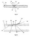
- FIGS. 27-30illustrate a method for deploying the introduction device in a cross-section of a lumen.
- FIG. 31illustrates a method for deploying a guidewire in a cross-section of a lumen.
- FIG. 32illustrates a portion of an arteriotomized lumen.
- FIG. 33illustrates section A-A of FIG. 28 .
- FIGS. 34-36illustrate a method for deploying a tensioner in a see-through portion of lumen wall.
- FIGS. 37-40illustrate methods for deploying various embodiments of the pressure clip in a cross-section of a lumen.
- FIG. 41illustrates a method of using a suture on a portion of an arteriotomized lumen.
- FIG. 42illustrates section B-B of FIG. 41 with the out-of-section suture.
- FIG. 43illustrates a method of using pledgets on a portion of an arteriotomized lumen.
- FIG. 44illustrates section C-C of FIG. 43 .
- FIG. 45illustrates an embodiment of the toggle deployment device in a first configuration.
- FIG. 46is a close-up view of FIG. 45 .
- FIG. 47illustrates an embodiment of the toggle deployment device in a second configuration.
- FIG. 48is a close-up view of FIG. 47 .
- FIG. 49illustrates a method of using the toggle deployment device in a cross-section of a lumen.
- FIG. 50illustrates FIG. 49 with a portion of the toggle deployment device shown in section D-D.
- FIG. 51illustrates a method of using the toggle deployment device in a cross-section of a lumen.
- FIG. 52illustrates FIG. 51 with a portion of the toggle deployment device shown in section E-E.
- FIGS. 53-55illustrate a method of using the toggle deployment device in a cross-section of a lumen.
- FIG. 56is a close-up view of FIG. 55 .
- FIG. 57illustrates an embodiment of a deployed toggle in a cross-section of a lumen.
- FIG. 58is a close-up view of FIG. 59 .
- FIGS. 59-61illustrate a method for deploying a toggle in a cross-section of a lumen.
- FIG. 62is a close-up view of FIG. 61 .
- FIG. 63illustrates a method for deploying a toggle in a cross-section of a lumen.
- FIGS. 64-66shown, in cross-section, a method for deploying the guidewire through an arteriotomy.
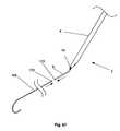
- FIGS. 67 and 68illustrate a method for attaching guidewire to the anchor.
- FIGS. 1 through 3illustrate a device for accessing a biological lumen, such as an arteriotomy device 2 .
- the arteriotomy device 2can have a delivery guide 4 .
- the delivery guide 4can be slidably attached to an anchor 6 .
- the anchor 6can be rigid, flexible or combinations thereof.
- the anchor 6can be resilient, deformable or combinations thereof.
- the anchor 6can be retractable and extendable from the delivery guide 4 .
- the delivery guide 4can have an introducer lumen 8 .
- the introducer lumen 8can have an introducer lumen exit port 10 .
- the introducer lumen exit port 10can be on the surface of the delivery guide 4 .
- the anchor 6can have an anchor angle section 12 .
- the anchor 6can have an anchor extension section 14 , for example a guide eye sheath or an attachable guidewire.
- the anchor extension section 14can extend from the anchor angle section 12 .
- the anchor extension section 14can be separate from and attached to, or integral with, the anchor angle section 12 .
- the anchor angle section 12can have an anchor angle first sub-section 16 , an anchor bend 20 and an anchor angle second sub-section 18 .
- the anchor angle first and/or second sub-sections 16 and/or 18can be part of the anchor bend 20 .
- the anchor bend 20can have a sharp or gradual curve.
- the radius of curvature for the anchor bend 20can be from about 0.1 mm (0.004 in.) to about 2.0 mm (0.079 in.).
- the anchor angle first sub-section 16can have an anchor angle first sub-section diameter 22 from about 0.38 mm (0.015 in.) to about 1.0 mm (0.039 in.), for example about 0.71 mm (0.028 in.).
- the anchor angle second sub-section 18can have an anchor angle second sub-section diameter 24 from about 0.38 mm (0.015 in.) to about 1.0 mm (0.039 in.), for example about 0.71 mm (0.028 in.).
- the anchor angle first sub-section 16can have a delivery longitudinal axis 26 .
- the anchor angle second sub-section 18can have an anchor longitudinal axis 28 .
- the intersection of the delivery longitudinal axis 26 and the anchor longitudinal axis 28can be an anchoring angle 30 .
- the anchoring angle 30can be from about 20° to about 90°, more narrowly from about 30° to about 60°, for example about 45°.
- any or all elements of the arteriotomy device 2 or other devices or apparatuses described hereincan be made from, for example, a single or multiple stainless steel alloys, nickel titanium alloys (e.g., Nitinol), cobalt-chrome alloys (e.g., ELGILOY® from Elgin Specialty Metals, Elgin, Ill.; CONICHROME® from Carpenter Metals Corp., Wyomissing, Pa.), molybdenum alloys (e.g., molybdenum TZM alloy, for example as disclosed in International Pub. No. WO 03/082363 A2, published 9 Oct.
- nickel titanium alloyse.g., Nitinol
- cobalt-chrome alloyse.g., ELGILOY® from Elgin Specialty Metals, Elgin, Ill.
- CONICHROME®from Carpenter Metals Corp., Wyomissing, Pa.
- molybdenum alloyse.g., moly
- tungsten-rhenium alloysfor example, as disclosed in International Pub. No. WO 03/082363
- polymerssuch as polyester (e.g., DACRON® from E. I. Du Pont de Nemours and Company, Wilmington, Del.), polypropylene, polytetrafluoroethylene (PTFE), expanded PTFE (ePTFE), polyether ether ketone (PEEK), nylon, polyether-block co-polyamide polymers (e.g., PEBAX® from ATOFINA, Paris, France), aliphatic polyether polyurethanes (e.g., TECOFLEX® from Thermedics Polymer Products, Wilmington, Mass.), polyvinyl chloride (PVC), polyurethane, thermoplastic, fluorinated ethylene propylene (FEP), absorbable or resorbable polymers such as polyglycolic acid (PGA), polylactic acid (PLA), polydioxanone, and pseudo
- any or all elements of the arteriotomy device 2can be or have a matrix for cell ingrowth or used with a fabric, for example a covering (not shown) that acts as a matrix for cell ingrowth.
- the matrix and/or fabriccan be, for example, polyester (e.g., DACRON® from E. I. du Pont de Nemours and Company, Wilmington, Del.), polypropylene, PTFE, ePTFE, nylon, extruded collagen, silicone or combinations thereof.
- the elements of the arteriotomy device 2 and/or the fabriccan be filled and/or coated with an agent delivery matrix known to one having ordinary skill in the art and/or a therapeutic and/or diagnostic agent.
- the agents within these matricescan include radioactive materials; radiopaque materials; cytogenic agents; cytotoxic agents; cytostatic agents; thrombogenic agents, for example polyurethane, cellulose acetate polymer mixed with bismuth trioxide, and ethylene vinyl alcohol; lubricious, hydrophilic materials; phosphor cholene; anti-inflammatory agents, for example non-steroidal anti-inflammatories (NSAIDs) such as cyclooxygenase-1 (COX-1) inhibitors (e.g., acetylsalicylic acid, for example ASPIRIN® from Bayer AG, Leverkusen, Germany; ibuprofen, for example ADVIL® from Wyeth, Collegeville, Pa.; indomethacin; mefenamic acid), CO
- FIG. 4illustrates that the anchor angle section 12 and the anchor extension section 14 can have a flexible elongated element.
- the flexible elongated elementcan be resilient and/or deformable.
- the flexible elongated elementcan have an integral, or multiple separate and fixedly attached, wound wire 32 .
- the anchor angle section 12can be in a sheath 34 .
- FIG. 5illustrates that the anchor angle section 12 can have a wire coating 36 , for example a lubricious coating and/or a coating made from urethane.
- FIGS. 6 and 7illustrate that the arteriotomy device 2 can have an introduction device 38 .
- the introduction device 38can be slidably attached to the introducer lumen 8 .
- the introduction device 38can have a hollow needle (as shown in FIG. 6 ).
- the introduction device 38can have a solid needle (as shown in FIG. 7 ).
- the introduction device 38can have a guidewire.
- the introduction device 38can have an introduction longitudinal axis 40 .
- the intersection of the introduction longitudinal axis 40 and the anchor longitudinal axis 28can be an introduction angle 42 .
- the introduction angle 42can be less than or equal to about 19°, more narrowly less than or equal to about 15°, yet more narrowly from about 5° to about 10°, for example about °10.
- the introduction device 38can have an introduction device diameter 44 .
- the introduction device diameter 44can be from about 0.25 mm (0.010 in.) to about 1.0 mm (0.039 in.), for example about 0.56 mm (0.022 in.).
- FIGS. 8 and 9illustrate that the arteriotomy device 2 can be configured so that the introduction device 38 can be deployed from the anchor 6 .
- the anchor 6can have an introduction device port 46 .
- the introduction device 38can be a hollow needle (as shown in FIG. 8 ). When fully deployed, the introduction device 38 can contact the introducer lumen exit port 10 .
- the introduction device 38can be a channel between the introducer lumen 8 and the anchor 6 .
- the anchor 6can have a port (not shown) configured to communicate with the biological lumen and the introduction device 38 .
- the introduction device 38can be a solid needle (as shown in FIG. 9 ).
- FIG. 10illustrates that a lumenal retainer 48 can have a first retracted configuration.
- the lumenal retainer 48can be seated in a lumenal retainer port 50 .
- the lumenal retainer port 50can be in the anchor 6 .
- the lumenal retainer 48can be a wire, scaffold or stent—for example made from a deformable or resilient material, such as a shape memory alloy—an inflatable balloon, or combinations thereof.
- Intralumenal inflatable balloonssuch as those inflated with saline solution or carbon dioxide, are known to those having ordinary skill in the art.
- the lumenal retainer 48can extend into the delivery guide 4 .
- FIGS. 11 and 12illustrate that the lumenal retainer 48 can have a second deployed configuration.
- FIG. 11shows that the lumenal retainer 48 can be a wire or balloon.
- FIG. 12shows that the lumenal retainer 48 can be a wire.
- the lumenal retainer 48can deploy away from the lumenal retainer port.
- the lumenal retainer 48can have a lumenal retainer deployed diameter 52 .
- the lumenal retainer deployed diameter 52can be from about 2.54 mm (0.100 in.) to about 10.2 mm (0.400 in.), for example about 6.35 mm (0.250 in.).
- FIG. 13illustrates that the arteriotomy device 2 can have an entry wall retainer port 54 .
- the entry wall retainer port 54can be at or near the anchor bend 20 .
- the entry wall retainer port 54can be at or near the anchor angle first sub-section 16 .
- the entry wall retainer port 54can be in fluid communication with a sensor or port (not shown) on or near the delivery guide 4 of the arteriotomy device 2 .
- FIG. 14illustrates that an entry wall retainer 56 can be deployed through the entry wall retainer port 54 .
- the entry wall retainer 56can have a first retracted configuration (as shown in FIG. 13 ).
- the entry wall retainer 56can have a second deployed configuration (as shown in FIG. 14 ).
- FIGS. 15 through 20illustrate various supplemental closure devices.
- the supplemental closure devicescan be completely or partially bioabsorbable, bioresorbable, bioadsorbable or combinations thereof.
- the supplemental closure devicescan be made from homografts, heterografts or combinations thereof.
- the supplemental closure devicescan be made from autografts, allografts or combinations thereof.
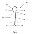
- FIG. 15illustrates a tensioner 58 .
- the tensioner 58can be resilient, deformable, or combinations thereof.
- the tensioner 58can have a tensioner longitudinal axis 60 .
- the tensioner 58can have a resilient element, such as a spring, for example a tensioner head 62 .
- the tensioner head 62can have a tensioner first shoulder 64 .
- the tensioner head 62can have a tensioner second shoulder 66 .
- the tensioner first and second shoulders 64 and 66can rotatably attached to a separate or integral tensioner first leg 68 and a separate or integral tensioner second leg 70 , respectively.
- the tensioner first and second legs 68 and 70can attach to tensioner first and second feet 72 and 74 , respectively.
- the tensioner legs 68 and 70can have tensioner leg diameters 76 .
- the tensioner leg diameters 76can be from about 0.1 mm (0.005 in.) to about 0.76 mm (0.030 in.), for example about 0.38 mm (0.015 in.).
- the tensioner first and second legs 68 and 70can have a tensioner inter-leg outer diameter 78 .
- the tensioner inter-leg outer diameter 78can be from about 1.3 mm (0.050 in.) to about 5.08 mm (0.200 in.), for example about 4.06 mm (0.160 in.).
- the tensioner shoulders 64 and/or 66 and/or the tensioner feet 72 and/or 74can extend to a greater radius from the tensioner longitudinal axis 60 than their respective tensioner inter-leg radius.
- FIG. 16illustrates a tensioner first strut 80 that can attach to the tensioner first leg 68 and the tensioner second leg 70 .
- the tensioner first leg 68can be resilient, deformable or combinations thereof.
- a tensioner second strut 82can attach to the tensioner first leg 68 and the tensioner second leg 70 .
- the tensioner second leg 70can be resilient and/or deformable.
- the tensioner 58can have no tensioner head 62 .
- the tensioner 58can have more than two tensioner struts 80 and 82 .
- FIG. 17illustrates a pressure clip 84 .
- the pressure clip 84can be resilient.
- the pressure clip 84can be deformable.
- the pressure clip 84can have a pressure clip longitudinal axis 86 .
- the pressure clip 84can have a pressure, clip head 88 .
- the pressure clip head 88can be rotatably attached to a separate or integral pressure clip first leg 90 .
- the pressure clip head 88can be rotatably attached to a separate or integral pressure clip second leg 92 .
- the pressure clipcan have a pressure clip first end 94 and a pressure clip second end 96 .
- the pressure clip first leg 90can terminate in the pressure clip first end 94 .
- the pressure clip second leg 92can terminate in the pressure clip second end 96 .
- the pressure clip first leg 90 and/or the pressure clip second leg 92can be biased toward the pressure clip longitudinal axis 86 .
- FIG. 18illustrates the pressure clip 84 that can have a pressure clip sheath 98 slidably attached to the pressure clip second leg 92 .
- the pressure clip first, and/or second ends 94 and/or 96can be pressure dissipaters, such as flat and/or curved portions, for example circular loops.
- the pressure clip first and/or second ends 94 and/or 96can be resilient and/or deformable.
- the pressure clip first leg 90can be rotatably attached to the pressure clip second leg 92 .
- the pressure clip first leg 90can be attached to the pressure clip second leg 92 via a rotatable, and/or deformable, and/or flexural joint in the pressure clip head 88 .
- FIG. 19illustrates a toggle 100 .
- the toggle 100can have a toggle first end 102 .
- the toggle 100can have a toggle second end 104 .
- the toggle first and/or second ends 102 and/or 104can be bars, dowels, rods, beams, or combinations thereof.
- the toggle 100can have a filament 106 .
- the filament 106can be fixedly attached at a filament first end 107 to the toggle first end 102 .
- the filament 106can be fixedly attached at a filament second end 109 to the toggle second end 104 .
- the filament 106can be resilient or deformable.
- the filament 106can be substantially flexible.
- FIG. 20illustrates the toggle 100 that can have the filament 106 that can be slidably attached to the toggle second end 104 at a hole 108 .
- the filament 106can frictionally fit the hole 108 .
- the filament 106can have no pawls 110 (not shown in FIG. 20 ).
- the filament 106can interference fit the hole 108 .
- the filament 106can have one or more pawls 110 .
- the hole 108can have one or more notches 112 .
- the notches 112can be internal to the hole 108 .
- the notches 112 and the pawls 110can be configured to allow the toggle second end 104 to slide toward the toggle first end 102 .
- the notches 112 and the pawls 110can be configured to provide an interference fit when the toggle second end 104 is attempted to be moved away from the toggle first end 102 .
- the elements of the arteriotomy device 2can be directly attached by, for example, melting, screwing, gluing, welding or use of an interference fit or pressure fit such as crimping, snapping, or combining methods thereof.
- the elementscan be integrated, for example, molding, die cutting, laser cutting, electrical discharge machining (EDM) or stamping from a single piece or material. Any other methods can be used as known to those having ordinary skill in the art.
- Integrated partscan be made from pre-formed resilient materials, for example resilient alloys (e.g., Nitinol, ELGILOY® that are preformed and biased into the post-deployment shape and then compressed into the deployment shape as known to those having ordinary skill in the art.
- resilient alloyse.g., Nitinol, ELGILOY® that are preformed and biased into the post-deployment shape and then compressed into the deployment shape as known to those having ordinary skill in the art.
- any elements of the arteriotomy device 2can be coated by dip-coating, brush-coating or spray-coating methods known to one having ordinary skill in the art
- these methodscan be used to coat the wound wire 32 with the wire coating 36 can be spray coated, dip-coated or brushed onto the wire 32 .
- the supplemental closure devicescan be covered with a fabric, for example polyester (e.g., DACRON® from E. I. du Pont de Nemours and Company, Wilmington, Del.), polypropylene, PTFE, ePTFE, nylon, extruded collagen, silicone or combinations 7 thereof.
- DACRON®from E. I. du Pont de Nemours and Company, Wilmington, Del.
- FIG. 21illustrates a method of inserting the anchor 6 into a biological lumen 114 , for example a blood vessel, such as a femoral artery.
- the biological lumen 114can have a lumen wall 116 and a lumen wall surface 118 .
- the anchor 6can be inserted into the biological lumen 114 using a Seldinger technique, modified Seldinger technique, or other method known to one having ordinary skill in the art.
- the anchor 6can create a first arteriotomy 120 .
- the anchor 6can be inserted into the lumen 114 so that the anchor angle second sub-section 18 can be substantially parallel with the lumen wall surface 118 .
- the anchor 6can be inserted into the lumen 114 so that the anchor angle second sub-section 18 can be substantially in contact with the lumen wall surface 118 .
- FIG. 22illustrates a method of deploying, as shown by arrow, the lumenal retainer 48 from the first retracted configuration to the second deployed configuration.
- the lumenal retainer 48can be deployed by extending a wire, scaffold or stent, or by inflating a balloon.
- the anchor angle second sub-section 18can be made substantially parallel with the lumen wall surface 118 .
- the anchor angle second sub-section 18can be made to be substantially in contact with the lumen wall surface 118 .
- FIG. 23illustrates a method of deploying, as shown by arrow 122 , the entry wall retainer 56 from the first retracted configuration to the second deployed configuration.
- the lumenal retainer 48can be substantially parallel with the lumen wall surface 118 .
- the lumenal retainer 48can be substantially in contact with the lumen wall surface 118 .
- a proximal forcecan be applied to the anchor 6 , for example by being applied to the delivery guide 4 .
- the anchor angle second sub-section 18can be made substantially parallel with the lumen wall surface 118 .
- the anchor angle second sub-section 18can be made to be substantially in contact with the lumen wall surface 118 .
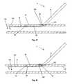
- FIGS. 24 and 25illustrate a method for deploying the introduction device 38 .
- the introduction device 38can egress from the introducer lumen 8 and the introducer lumen exit port 10 .
- the introduction device 38can be pushed, as shown by arrow, into and through the lumen wall 116 .
- the introduction device 38can form a second arteriotomy 128 .
- the introduction device 38can be pushed, as shown by arrow, adjacent to or through the anchor 6 .
- the anchor 6can be configured to have ports suitable to allow the introduction device 38 to pass through the anchor 6 .
- a tip of the introduction device 38can enter the lumen 114 .
- the introduction device 38can pass through an introduction run 132 and an introduction rise 134 .
- the introduction run 132can be the component of the length of the introduction device 38 in the lumen wall 116 that is parallel to the lumen wall 116 .
- the introduction run 132can be the component of the length parallel to the lumen wall 116 between the opening of the second arteriotomy 128 on the outside of the lumen wall 116 and the opening of the second arteriotomy 128 on the inside lumen wall surface 118 .
- the introduction run 132can be from about 0.10 cm (0.010 in.) to about 3.810 cm (1.500 in.), for example about 0.64 cm (0.25 in.).
- the introduction rise 134can be the component of the length of the introduction device 38 in the lumen wall 116 that is perpendicular to the lumen wall 116 .
- the introduction rise 134can be the component of the length perpendicular to the lumen wall 116 between the opening of the second arteriotomy 128 on the outside of the lumen wall 116 and the opening of the second arteriotomy 128 on the inside lumen wall surface 118 .
- the introduction rise 134can be from about 0.51 mm (0.020 in.) to about 5.08 mm (0.200 in.), for example about 1.0 mm (0.040 in.).
- An introduction slopecan be the ratio of the introduction rise 134 to the introduction run 132 .
- the introduction slopecan be from about 1 ⁇ 2 to about 1/40 or less, for example about 1 ⁇ 6, also for example about 1 ⁇ 3.
- the introduction slopecan be, for examples, equal to or less than about 1 ⁇ 2 or 1 ⁇ 3, more narrowly equal to or less than about 1 ⁇ 3 or 1 ⁇ 4, yet more narrowly equal to or less than about 1 ⁇ 5 or 1 ⁇ 6, even still more narrowly than about equal to or less than about 1/10.
- the introduction rise 134 and the introduction run 132can be components of an introduction vector.
- the introduction run 132can be the component of the introduction vector parallel to the lumen wall 116 .
- the introduction rise 134can be the component of the introduction vector perpendicular to the lumen wall 116 .
- the introduction vectorcan be a vector from an outer opening 136 to an inner opening 138 .
- the outer opening 136can be a temporary or permanent opening on the outside of the lumen wall 116 formed by the introduction device 38 .
- the inner opening 138can be a temporary or permanent opening on the inside of the vessel wall.
- FIG. 26illustrates that the introduction-device 38 , for example a hollow needle, can act as a pathway for a lumenal tool, for example tools such as a guidewire 168 , to be deployed, as shown by arrow, into the lumen 114 .
- the introduction device 38for example a solid needle, can be removed from the second arteriotomy 128 and the lumenal tool can be deployed through, for example, the introducer lumen exit port 10 , and the second arteriotomy 128 .
- the introduction device 38can be the lumenal tool, for example a guidewire.
- the introduction device 38can be further deployed and used as a lumenal tool after passing through the lumen wall 116 .
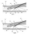
- FIGS. 27 through 30illustrates a method of deploying the introduction device 38 that can have a pre-formed bend.
- the arteriotomy device 2can be configured to deploy the introduction device 38 at the introduction angle 42 from about 0° to about 5°, for example about 0°.
- the introduction device 38can be pushed, as shown by arrow, through the lumen wall 116 .
- the introduction device 38can cleave a plane in the lumen wall 116 .
- the planecan be substantially parallel with the lumen wall surface 118 .
- the introduction device 38can be adjacent to the adventitia in a blood vessel.
- the introduction device 38can be advanced along the subintimal or submedial cleavage plane in a blood vessel.
- a subintimal angioplastycan be performed as known to one having ordinary skill in the art.
- a remote endarterectomycan be performed as known to one having ordinary skill in the art.
- Bent and straight introduction devices 38can be swapped during use to selectively cleave the lumen wall 116 .
- Tools, such as guidewirescan be inserted through hollow introduction devices 38 to selectively cleave the lumen wall 116 .
- FIG. 29when the bend in the introduction device 38 moves into the lumen wall 116 , the introduction device 38 can rotate, as shown by arrow, toward the biological lumen 114 . As shown in FIG. 30 , the bend in the introduction device 38 can continue to rotate the introduction device 38 toward the biological lumen 114 . As described infra, the introduction device 38 can enter the lumen 114 .
- FIG. 31illustrates that the introduction device 38 that can have the bend can act as a pathway for a lumenal tool, as described infra.
- An introducer sheathcan be inserted over the guidewire 168 and/or the introduction device 38 .
- the introducer sheathcan be less than about 22 French (7.3 mm, 0.29 in. diameter) or less than the diameter of the lumen to which the introducer sheath is introduced.
- the introducer sheathcan be, for examples, about 6 French (2.3 mm, 0.092 in. diameter), and about 8 French (2.67 mm, 0.105 in. diameter).
- the introducer sheathcan be known to one having ordinary skill in the art, for example the introducer sheath described in U.S. Pat. No. 5,183,464 to Dubrul, et al.
- the introducer sheathcan be inserted into the second arteriotomy 128 .
- the introducer sheathcan expand the second arteriotomy 128 to a workable size.
- the introducer sheathcan be inserted into the second arteriotomy 128 before and/or after and/or concurrently with the supplemental closure device is deployed and/or other closure method is used.
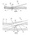
- FIGS. 32 and 33illustrate an exemplary biological lumen 114 after the arteriotomy device 2 has been deployed to, and removed from, the biological lumen 114 .
- the biological lumen 114can have the first and second arteriotomies 120 and 128 .
- the biological lumen 114can have a second arteriotomy 128 .
- the biological lumen 114can have a first web 140 on one side of the arteriotomy (shown for the second arteriotomy 128 ), and a second web 142 on the opposite side of the arteriotomy 120 or 128 .
- the natural pressure, shown by arrows, from the first and second webs 140 and 142can self-seal the arteriotomy 120 or 128 .
- One or more supplemental closure devicescan be deployed to the first and/or second arteriotomies 120 and/or 128 .
- the supplemental closure devicescan provide a force or restraint to aid hemostasis.
- the supplemental closure devicescan be permanently or temporarily deployed.
- the supplemental closure devicescan biodissolve after hemostasis is achieved and/or after the relevant arteriotomy 120 or 128 is substantially or completely healed.
- the force from the supplemental closure devicecan be maintained from about 15 minutes to about 24 hours or more, for example about 120 minutes.
- FIG. 34illustrates a tensioner 58 in a compressed configuration. Compressive forces, shown by arrows, can compress the tensioner first and second legs 68 and 70 .
- the tensioner inter-leg outer diameter 78can be from about 0.51 mm (0.020 in.) to about 2.54 mm (0.100 in.), for example about 1.5 mm (0.060 in.).
- FIGS. 35 and 36illustrate a method of deploying the tensioner 58 .
- the tensioner 58can be in a compressed configuration.
- the tensioner 58can be exposed to the compressive forces, as shown by arrows 144 .
- the compressive forcescan be applied by a retractable sheath, clamps, other methods known to one having ordinary skill in the art, or combinations thereof.
- a deployment forceshown by arrow 146 , can deploy the tensioner 58 into the arteriotomy 120 or 128 .
- the arteriotomy 120 or 128can have an arteriotomy diameter 148 .
- the arteriotomy diameter 148can be from about 0.5 mm (0.020 in.) to about 400 mm (15 in.), yet a narrower range from about 1.0 mm (0.040 in.) to about 10.2 mm (0.400 in.), for example about 2.54 mm (0.100 in.).
- the tensioner inter-leg outer diameter 78can be smaller than the arteriotomy diameter 148 .
- the tensioner first and second shoulders 64 and 66can be wide enough to interference fit with the arteriotomy 120 or 128 .
- the tensioner first and second shoulders 64 and 66can dissipate force on the lumen wall surface 118 .
- the compressive forcescan be removed from the tensioner 58 .
- the tensioner first and second leg 68 and 70can expand, as shown by arrows.
- the tensioner 58can force the arteriotomy 120 or 128 into a substantially or completely flat and/or closed and/or stretched configuration.
- the walls of the arteriotomy 120 or 128can come into close contact.
- the arteriotomy 120 or 128can have an arteriotomy width 150 and an arteriotomy height 152 .
- the arteriotomy width 150can be about half the circumference of the arteriotomy 120 or 128 .
- the arteriotomy width 150can be from about 1.0 mm (0.040 in.) to about 10.2 mm (0.400 in.), for example about 4.06 mm (0.160 in.).
- the arteriotomy height 152can be about the tensioner leg diameter 76 .
- the arteriotomy height 152can be less than about 0.51 mm (0.020 in.), more narrowly, less than about 0.38 mm (0.015 in.);
- the arteriotomy height 152can be from about 0.25 mm (0.010 in.) to about 1.3 mm (0.050 in.), for example about 0.38 mm (0.015 in.).
- the arteriotomy height 152can be small enough to enable cell growth, blood clotting, acoustic sealing, heat sealing, gluing, enhanced self-sealing and combinations thereof across the arteriotomy 120 or 128 .
- the tensioner first and second shoulders 64 and 66can be wide enough to interference fit with the arteriotomy 120 or 128 .
- the tensioner first and second feet 72 and 74can be wide enough to interference fit with the arteriotomy 120 or 128 .
- the tensioner first and second feet 72 and 74can dissipate force on the lumen wall surface 118 .
- the arteriotomy 120 or 128can be plugged, and/or packed, and/or tamponed before, and/or concurrent with, and/or after using any of any of the supplemental closure devices infra and/or supra, the self-sealing closure method, or combinations thereof.
- the plug, pack, tampon, or combinations thereofcan be made from gelfoam, collagen, other implantable and biocompatible tampon materials known to those having ordinary skill in the art, or combinations thereof.
- FIGS. 37 through 40illustrate deploying the pressure clip 84 to the arteriotomy 120 or 128 .
- FIG. 37illustrates extending, and/or thinning, and/or straightening, and/or tensioning the pressure clip second end 96 .
- the pressure clip sheath 98can be translated, as shown by arrow, along the pressure clip second leg 92 and onto the pressure clip second end 96 .
- the pressure clip 84can be deployed to the arteriotomy after the pressure clip second end 96 is extended, and/or thinned, and/or straightened, and/or tensioned.
- the pressure clip second leg 92can be rotated with respect to the pressure clip head 88 , so that the pressure clip second leg 92 and the pressure clip head 88 are substantially aligned.
- the pressure clip second leg 92can be deployed, as shown by the arrow, through the first arteriotomy 120 .
- the pressure clip second leg 92can be deployed through the lumen wall 116 (e.g., if there is no existing first arteriotomy 120 , if the first arteriotomy 120 is not suitably located with respect to the second arteriotomy 128 ).
- FIG. 39illustrates contracting, and/or widening, and/or releasing and/or relaxing the pressure clip second end 96 .
- the pressure clip sheath 98can be translated, as shown by arrow, along the pressure clip second leg 92 and off of the pressure clip second end 96 .
- the pressure clip second end 96can be contracted, and/or widened, and/or released and/or relaxed after the pressure clip 84 is deployed to the arteriotomy.
- the pressure clip second leg 92can be released or deformed so as to rotate with respect to the pressure clip head 88 .
- the pressure clip head 88can seat in the first arteriotomy 120 .
- the pressure clip first and second legs 90 and 92can apply force, as shown by arrows, to the first and second webs 140 and 142 , respectively.
- FIGS. 41 and 42illustrate a method of deploying a stitch 154 surrounding and/or through the arteriotomy 120 or 128 .
- the stitch 154can be tightened to apply additional pressure to the arteriotomy 120 or 128 .
- the stitch 154can have a knot 156 , or other tying configuration or device, for example a pledget or clamp.
- FIGS. 43 and 44illustrate a method of deploying the filament 106 adjacent to and/or through the arteriotomy 120 or 128 .
- the filament 106can be attached to a first pledget 158 a by a first knot 156 a or other tying configuration or device.
- the filament 106can be attached to a second pledget 158 b by a second knot 156 b or other tying configuration or device.
- the first and second pledgets 158 a and 158 bcan be other pressure diffusers known to one having ordinary skill in the art, such as the toggles 100 described infra and supra.
- FIGS. 45 and 46illustrate a toggle deployment device 159 that can be in a first retracted configuration.
- the toggle deployment device 159can have a pressure check port 160 .
- the pressure check port 160can be in fluid communication with a sensor or port on or near the handle (not shown) of the toggle deployment device 159 , such as an external lumen where blood flow can be observed, for example from flow from the end of an external tube or port and/or through a transparent or translucent window.
- the pressure check port 160can facilitate deployment of the toggle deployment device 159 to a location where the pressure check port 160 is introduced to pressure, for example when the pressure check port 160 enters the biological lumen 114 .
- the sensor or port on or near the handle of the toggle deployment device 159will signal that the pressure check port 160 has been placed into the biological lumen 114 (e.g., by displaying a small amount of blood flow).
- the pressure check port 160can be deployed into the biological lumen 114 and then withdrawn from the biological lumen 114 to the point where the lumen wall 116 just stops the pressure in the pressure check port 160 .
- the entry wall retainer port 54can additionally perform the function as described herein for the pressure check port 160 .
- the toggle deployment device 159can have a delivery needle port 161 .
- FIGS. 47 and 48illustrate the toggle deployment device 159 that can be in a second delivery configuration.
- a delivery needle 162can be slidably attached to the toggle deployment device 159 .
- the delivery needle 162can egress from the delivery needle port 161 when the toggle deployment device 159 is in the second delivery configuration.
- FIGS. 49 and 50illustrate that the toggle deployment device 159 can be deployed into the arteriotomy 120 or 128 at a location where the pressure check port 160 can be located in the biological lumen 114 .
- the delivery needle port 161can be in, or adjacent to, the lumen wall 116 .
- FIGS. 51 and 52illustrate that the toggle deployment device 159 can be placed in the second delivery configuration.
- the delivery needle portis in, or adjacent to, the lumen wall 116 when the toggle deployment device 159 is placed in the second delivery configuration
- the delivery needle 162can enter the lumen wall 116 .
- the delivery needle 162can enter the second web 142 .
- the delivery needle 162can exit the second web 142 and enter, as shown by arrows, the biological lumen 114 .
- FIG. 53illustrates that a pusher 164 can be slidably attached to the delivery needle 162 .
- the delivery needle 162can have a needle tip port 166 .
- the toggle 100can be in the delivery needle 162 .
- the toggle 100can be configured in the delivery needle 162 such that the toggle first end 102 can be located on the needle tip port 166 —side of the pusher 164 .
- FIG. 54illustrates that the pusher 164 can be moved, as shown by arrow, toward the needle tip port 166 .
- the delivery needle 162can be moved back relative to the pusher 164 , the pusher 164 can be moved forward relative to the delivery needle 162 , or combinations thereof.
- the pusher 164can push the toggle first end 102 out of the delivery needle 162 .
- the pusher 164can push the toggle first end 102 into the biological lumen 114 .
- FIGS. 55 and 56illustrate that the toggle deployment device 159 can be in a first retracted configuration after deploying the toggle first end 102 into the biological lumen 114 .
- the toggle second end 104can be in the toggle deployment device 159 .
- the filament 106can extend though the delivery needle port 161 .
- FIGS. 57 and 58illustrate that the toggle 100 can be deployed across the lumen wall.
- the toggle deployment device 159When the toggle deployment device 159 is removed from the arteriotomy, the toggle second end 104 can deploy on the outside of the lumen wall 116 from the delivery needle port 161 .
- the toggle first end 102can form an interference fit with the lumen wall surface 118 .
- the toggle second end 104can form an interference fit with the outside of the lumen wall 116 or the surrounding tissue, such as subcutaneous tissue.
- the toggle second end 104can be slidably translated along the filament 106 toward the lumen wall 116 , for example for the toggle 100 illustrated in FIG. 20 .
- the length of the filament 106 on the opposite side of toggle second end 104 from the toggle first end 102can be cut, snapped, torn or otherwise removed.
- FIGS. 59 through 63illustrate a method for deploying the toggle 100 .
- the delivery needle 162can egress, as shown by arrow, from a toggle deployment delivery port 163 .
- the toggle deployment delivery port 163can be in the delivery guide 4 .
- the delivery needle 162 ′can be advanced toward the lumen 114 .
- FIG. 60illustrates that the delivery needle 162 can be deployed through the lumen wall.
- the delivery needle 162When the delivery needle 162 is deployed through the lumen wall 116 , the delivery needle can intersect, or pass adjacent to, the second arteriotomy.
- FIGS. 61 and 62illustrate that the pusher 164 can be advanced, as shown by arrow, through the delivery needle 162 .
- the toggle first end 102can egress from the needle tip port 166 .
- the toggle first end 102can deploy into the lumen 114 .
- FIG. 63illustrates that the delivery needle 162 can be retracted into the delivery guide 4 and/or the filament 106 can be pulled taught, both shown by arrow.
- the toggle first end 102can form an interference fit with the lumen wall surface 118 .
- the toggle second end 104(not shown in FIG. 63 ) can be slidably translated on the filament 106 down to, and form an interference fit with, the outside of the lumen wall 116 .
- the length of the filament 106 on the opposite side of toggle second end 104 from the toggle first end 102can be cut, snapped, torn or otherwise removed.
- FIG. 64illustrates an introducer needle 165 that can have an end inserted, as shown by arrow, through the lumen wall 116 and into the lumen 114 , for example by using the Seldinger technique.
- the introducer needle 165can be hollow and/or have a longitudinal channel.
- FIG. 65illustrates that the guidewire 168 can be deployed, shown by arrows, through the hollow and/or longitudinal channel of the introducer needle 165 .
- FIG. 66illustrates that the introducer needle 165 can be removed, as shown by arrow, from the lumen wall 116 .
- the guidewire 168can remain substantially in place. After the introducer needle 165 is removed, a portion of the guidewire 168 can be outside the lumen 114 and another portion of the guidewire 168 can be inside the lumen 114 .
- FIG. 67illustrates a method of fixedly or slidably attaching the guidewire 168 to the anchor 6 .
- a guidewire proximal end 170can be placed in proximity to an anchor distal end 172 .
- the guidewire proximal end 170can then be attached, as shown by arrows, to the anchor distal end 172 .
- the guidewire proximal end 170can be attached to the anchor distal end 172 while some or all of the guidewire 168 is in the lumen 114 .
- the guidewire proximal end 170can be configured to snap-fit, interference fit, slidably attach or combinations thereof, to the anchor 6 .
- the guidewire 168can act as the anchor extension section 14 and/or the lumenal tool.
- FIG. 68illustrates the guidewire 168 attached to the anchor 6 .
Landscapes
- Health & Medical Sciences (AREA)
- Life Sciences & Earth Sciences (AREA)
- Animal Behavior & Ethology (AREA)
- General Health & Medical Sciences (AREA)
- Veterinary Medicine (AREA)
- Engineering & Computer Science (AREA)
- Biomedical Technology (AREA)
- Heart & Thoracic Surgery (AREA)
- Public Health (AREA)
- Surgery (AREA)
- Biophysics (AREA)
- Hematology (AREA)
- Anesthesiology (AREA)
- Pulmonology (AREA)
- Medical Informatics (AREA)
- Nuclear Medicine, Radiotherapy & Molecular Imaging (AREA)
- Molecular Biology (AREA)
- Pathology (AREA)
- Cardiology (AREA)
- Gastroenterology & Hepatology (AREA)
- Surgical Instruments (AREA)
- Prostheses (AREA)
Abstract
Description
Claims (13)
Priority Applications (1)
| Application Number | Priority Date | Filing Date | Title |
|---|---|---|---|
| US11/544,149US8012168B2 (en) | 2004-05-12 | 2006-10-06 | Access and closure device and method |
Applications Claiming Priority (2)
| Application Number | Priority Date | Filing Date | Title |
|---|---|---|---|
| US10/844,247US20050267520A1 (en) | 2004-05-12 | 2004-05-12 | Access and closure device and method |
| US11/544,149US8012168B2 (en) | 2004-05-12 | 2006-10-06 | Access and closure device and method |
Related Parent Applications (1)
| Application Number | Title | Priority Date | Filing Date |
|---|---|---|---|
| US10/844,247ContinuationUS20050267520A1 (en) | 2004-05-12 | 2004-05-12 | Access and closure device and method |
Publications (2)
| Publication Number | Publication Date |
|---|---|
| US20070032802A1 US20070032802A1 (en) | 2007-02-08 |
| US8012168B2true US8012168B2 (en) | 2011-09-06 |
Family
ID=35426402
Family Applications (8)
| Application Number | Title | Priority Date | Filing Date |
|---|---|---|---|
| US10/844,247AbandonedUS20050267520A1 (en) | 2004-05-12 | 2004-05-12 | Access and closure device and method |
| US11/544,196Expired - Fee RelatedUS8002791B2 (en) | 2004-05-12 | 2006-10-06 | Access and closure device and method |
| US11/544,149Expired - Fee RelatedUS8012168B2 (en) | 2004-05-12 | 2006-10-06 | Access and closure device and method |
| US11/544,177Expired - Fee RelatedUS7998169B2 (en) | 2004-05-12 | 2006-10-06 | Access and closure device and method |
| US11/545,272Expired - Fee RelatedUS8002793B2 (en) | 2004-05-12 | 2006-10-06 | Access and closure device and method |
| US11/544,365Expired - Fee RelatedUS8002792B2 (en) | 2004-05-12 | 2006-10-06 | Access and closure device and method |
| US13/332,899AbandonedUS20120089166A1 (en) | 2004-05-12 | 2011-12-21 | Access and Closure Device and Method |
| US14/965,673AbandonedUS20160095621A1 (en) | 2004-05-12 | 2015-12-10 | Access and closure device and method |
Family Applications Before (2)
| Application Number | Title | Priority Date | Filing Date |
|---|---|---|---|
| US10/844,247AbandonedUS20050267520A1 (en) | 2004-05-12 | 2004-05-12 | Access and closure device and method |
| US11/544,196Expired - Fee RelatedUS8002791B2 (en) | 2004-05-12 | 2006-10-06 | Access and closure device and method |
Family Applications After (5)
| Application Number | Title | Priority Date | Filing Date |
|---|---|---|---|
| US11/544,177Expired - Fee RelatedUS7998169B2 (en) | 2004-05-12 | 2006-10-06 | Access and closure device and method |
| US11/545,272Expired - Fee RelatedUS8002793B2 (en) | 2004-05-12 | 2006-10-06 | Access and closure device and method |
| US11/544,365Expired - Fee RelatedUS8002792B2 (en) | 2004-05-12 | 2006-10-06 | Access and closure device and method |
| US13/332,899AbandonedUS20120089166A1 (en) | 2004-05-12 | 2011-12-21 | Access and Closure Device and Method |
| US14/965,673AbandonedUS20160095621A1 (en) | 2004-05-12 | 2015-12-10 | Access and closure device and method |
Country Status (8)
| Country | Link |
|---|---|
| US (8) | US20050267520A1 (en) |
| EP (4) | EP1748735A4 (en) |
| JP (5) | JP4871268B2 (en) |
| CN (2) | CN104257410A (en) |
| AU (1) | AU2005244834A1 (en) |
| CA (1) | CA2566743A1 (en) |
| IL (2) | IL179173A (en) |
| WO (1) | WO2005112791A2 (en) |
Cited By (7)
| Publication number | Priority date | Publication date | Assignee | Title |
|---|---|---|---|---|
| US9572558B2 (en) | 2012-02-29 | 2017-02-21 | Vivasure Medical Limited | Devices and methods for delivering implants for percutaneous perforation closure |
| US9610070B2 (en) | 2007-06-15 | 2017-04-04 | Vivasure Medical Limited | Closure device |
| US9850013B2 (en) | 2013-03-15 | 2017-12-26 | Vivasure Medical Limited | Loading devices and methods for percutaneous perforation closure systems |
| US10206668B2 (en) | 2014-12-15 | 2019-02-19 | Vivasure Medical Limited | Implantable sealable member with mesh layer |
| US10433826B2 (en) | 2014-12-15 | 2019-10-08 | Vivasure Medical Limited | Closure apparatus with flexible sealable member and flexible support member |
| US11311280B2 (en) | 2015-12-15 | 2022-04-26 | Vivasure Medical Limited | Arteriotomy closure apparatus with slotted shoe for advantageous pressure distribution |
| US11357486B2 (en) | 2009-12-30 | 2022-06-14 | Vivasure Medical Limited | Closure system and uses thereof |
Families Citing this family (52)
| Publication number | Priority date | Publication date | Assignee | Title |
|---|---|---|---|---|
| US7410480B2 (en)* | 2004-04-21 | 2008-08-12 | Acclarent, Inc. | Devices and methods for delivering therapeutic substances for the treatment of sinusitis and other disorders |
| US20050251178A1 (en)* | 2004-05-03 | 2005-11-10 | Tirabassi Michael V | Hooked rod delivery system for use in minimally invasive surgery |
| US20050267520A1 (en) | 2004-05-12 | 2005-12-01 | Modesitt D B | Access and closure device and method |
| US7678133B2 (en) | 2004-07-10 | 2010-03-16 | Arstasis, Inc. | Biological tissue closure device and method |
| EP1879505B1 (en)* | 2005-04-29 | 2012-10-24 | Vivasure Medical Limited | An interventional medical closure device |
| CN103190942A (en) | 2005-05-12 | 2013-07-10 | 阿尔斯塔西斯公司 | Access and closure device and method |
| US20060270989A1 (en)* | 2005-05-27 | 2006-11-30 | Mcmichael Donald J | Gastric fastening system |
| US7549200B2 (en)* | 2005-05-27 | 2009-06-23 | Kimberly-Clark Worldwide, Inc. | Clamp for flexible tube |
| US20100168767A1 (en) | 2008-06-30 | 2010-07-01 | Cardiva Medical, Inc. | Apparatus and methods for delivering hemostatic materials for blood vessel closure |
| US8911472B2 (en) | 2005-12-13 | 2014-12-16 | Cardiva Medical, Inc. | Apparatus and methods for delivering hemostatic materials for blood vessel closure |
| US20080097491A1 (en)* | 2006-08-28 | 2008-04-24 | Fred Gobel | Tissue to tissue anchoring device and method of using the same |
| WO2008027366A2 (en)* | 2006-08-28 | 2008-03-06 | Vascular Precision | Devices and methods for creating and closing controlled openings in tissue |
| US7582098B2 (en)* | 2006-08-28 | 2009-09-01 | Kimberly-Clark Wolrdwide, Inc. | Percutaneous gastrointestinal anchoring kit |
| US8858490B2 (en) | 2007-07-18 | 2014-10-14 | Silk Road Medical, Inc. | Systems and methods for treating a carotid artery |
| US20090105744A1 (en)* | 2007-10-17 | 2009-04-23 | Modesitt D Bruce | Methods for forming tracts in tissue |
| US9358002B2 (en)* | 2008-04-01 | 2016-06-07 | Covidien Lp | Anchoring device |
| US10376261B2 (en) | 2008-04-01 | 2019-08-13 | Covidien Lp | Anchoring suture |
| JP5695564B2 (en)* | 2008-07-07 | 2015-04-08 | アピカ カーディオヴァスキュラー アイルランド リミテッド | Tissue access site system and method |
| JP2011528606A (en)* | 2008-07-21 | 2011-11-24 | アルスタシス,インコーポレイテッド | Apparatus and method for forming a tract in tissue |
| JP2011528605A (en)* | 2008-07-21 | 2011-11-24 | アルスタシス,インコーポレイテッド | Device, method, and kit for forming a tube in tissue |
| US8574245B2 (en) | 2008-08-13 | 2013-11-05 | Silk Road Medical, Inc. | Suture delivery device |
| EP2323566A2 (en) | 2008-08-13 | 2011-05-25 | Silk Road Medical, Inc. | Suture delivery device |
| CN102405022B (en)* | 2009-03-14 | 2015-02-04 | 瓦索斯蒂奇股份有限公司 | Vessel access and closure device |
| US20110125178A1 (en)* | 2009-05-15 | 2011-05-26 | Michael Drews | Devices, methods and kits for forming tracts in tissue |
| AU2010298315A1 (en)* | 2009-09-22 | 2012-04-19 | Arstasis, Inc. | Devices, methods, and kits for forming tracts in tissue |
| AU2011203850A1 (en) | 2010-01-11 | 2012-08-02 | Arstasis, Inc. | Device for forming tracts in tissue |
| EP2584977A4 (en) | 2010-06-26 | 2017-08-09 | Vasostitch, Inc. | Method and apparatus for transapical access and closure |
| WO2012090069A2 (en) | 2010-12-30 | 2012-07-05 | Vivasure Medical Limited | Surgical closure systems and methods |
| EP2717781B1 (en) | 2011-06-07 | 2019-02-06 | St. Jude Medical Puerto Rico LLC | Large bore closure device |
| US20130060279A1 (en) | 2011-09-02 | 2013-03-07 | Cardiva Medical, Inc. | Catheter with sealed hydratable hemostatic occlusion element |
| EP2747667B1 (en) | 2011-11-16 | 2016-03-09 | St. Jude Medical Puerto Rico LLC | Vascular closure system |
| WO2013074490A1 (en) | 2011-11-16 | 2013-05-23 | St. Jude Medical Puerto Rico Llc | Large bore vascular closure device with inner and outer seals |
| WO2013081905A1 (en) | 2011-11-28 | 2013-06-06 | St. Jude Medical Puerto Rico Llc | Anchor device for large bore vascular closure |
| JP6164698B2 (en)* | 2011-12-07 | 2017-07-19 | リサーチ メディカル プロプライエタリー リミテッドResearch Medical Pty Ltd | Surgical trocar |
| US9358077B2 (en) | 2012-03-14 | 2016-06-07 | St. Jude Medical Puerto Rico Llc | Markers for tissue tract depth indication and methods |
| US20130317438A1 (en) | 2012-05-25 | 2013-11-28 | Arstasis, Inc. | Vascular access configuration |
| US20130317481A1 (en) | 2012-05-25 | 2013-11-28 | Arstasis, Inc. | Vascular access configuration |
| WO2014022509A1 (en) | 2012-08-01 | 2014-02-06 | Arstasis, Inc. | Access closure configuration |
| US20140039546A1 (en)* | 2012-08-01 | 2014-02-06 | Arstasis Inc. | Access closure configuration |
| WO2014021937A1 (en) | 2012-08-03 | 2014-02-06 | St. Jude Medical Puerto Rico Llc | Large bore introducer with improved seal |
| US10159479B2 (en) | 2012-08-09 | 2018-12-25 | Silk Road Medical, Inc. | Suture delivery device |
| WO2014031147A1 (en) | 2012-08-24 | 2014-02-27 | St. Jude Medical Puerto Rico Llc | Balloon bailout and bioadhesive delivery device for suture based closure and methods |
| US9554785B2 (en) | 2012-12-21 | 2017-01-31 | Essential Medical, Inc. | Vascular locating systems and methods of use |
| US10136885B2 (en) | 2013-03-11 | 2018-11-27 | St. Jude Medical Puerto Rico Llc | Three suture large bore closure device and methods |
| US9055933B2 (en) | 2013-03-12 | 2015-06-16 | St. Jude Medical Puerto Rico Llc | Large bore closure secondary hemostasis bioadhesive delivery systems and methods |
| EP3007631A4 (en)* | 2013-06-11 | 2016-11-16 | Promed Inc | Improved vessel access closure |
| WO2015175537A1 (en) | 2014-05-16 | 2015-11-19 | Silk Road Medical, Inc. | Vessel access and closure assist system and method |
| EP3397190A1 (en)* | 2015-12-28 | 2018-11-07 | Koninklijke Philips N.V. | Elongated interventional device for optical shape sensing |
| US10531868B2 (en) | 2017-12-01 | 2020-01-14 | Cardiva Medical, Inc. | Apparatus and methods for accessing and closing multiple penetrations on a blood vessel |
| SG11202006260XA (en)* | 2018-01-04 | 2020-07-29 | Seger Surgical Solutions Ltd | Tissue alignment for surgical closure |
| WO2023043661A1 (en)* | 2021-09-17 | 2023-03-23 | Teleflex Life Sciences Limited | Depth gauge system |
| EP4565145A1 (en)* | 2022-08-09 | 2025-06-11 | Boston Scientific Scimed, Inc. | Tissue traction devices, systems |
Citations (232)
| Publication number | Priority date | Publication date | Assignee | Title |
|---|---|---|---|---|
| US2857925A (en) | 1954-10-01 | 1958-10-28 | Higginbotham Richard Stopford | Ground gripping ferrule for use on walking sticks, crutches and the like |
| US3727614A (en) | 1971-05-13 | 1973-04-17 | Merck & Co Inc | Multiple dosage inoculator |
| US3730185A (en) | 1971-10-29 | 1973-05-01 | Cook Inc | Endarterectomy apparatus |
| US4006747A (en) | 1975-04-23 | 1977-02-08 | Ethicon, Inc. | Surgical method |
| US4744364A (en)* | 1987-02-17 | 1988-05-17 | Intravascular Surgical Instruments, Inc. | Device for sealing percutaneous puncture in a vessel |
| US4774949A (en) | 1983-06-14 | 1988-10-04 | Fogarty Thomas J | Deflector guiding catheter |
| US4850960A (en)* | 1987-07-08 | 1989-07-25 | Joseph Grayzel | Diagonally tapered, bevelled tip introducing catheter and sheath and method for insertion |
| US4890611A (en) | 1988-04-05 | 1990-01-02 | Thomas J. Fogarty | Endarterectomy apparatus and method |
| US4921484A (en) | 1988-07-25 | 1990-05-01 | Cordis Corporation | Mesh balloon catheter device |
| US4955897A (en) | 1988-08-22 | 1990-09-11 | Ship Arthur G | Tissue forceps |
| US4962755A (en) | 1989-07-21 | 1990-10-16 | Heart Tech Of Minnesota, Inc. | Method for performing endarterectomy |
| US5183464A (en) | 1991-05-17 | 1993-02-02 | Interventional Thermodynamics, Inc. | Radially expandable dilator |
| US5271415A (en) | 1992-01-28 | 1993-12-21 | Baxter International Inc. | Guidewire extension system |
| US5304184A (en) | 1992-10-19 | 1994-04-19 | Indiana University Foundation | Apparatus and method for positive closure of an internal tissue membrane opening |
| US5336221A (en) | 1992-10-14 | 1994-08-09 | Premier Laser Systems, Inc. | Method and apparatus for applying thermal energy to tissue using a clamp |
| US5358507A (en) | 1991-07-26 | 1994-10-25 | Pat O. Daily | Thromboendarterectomy suction dissector |
| US5364359A (en) | 1990-03-01 | 1994-11-15 | Advanced Protective Injection Systems Medical B.V. | Syringe with retractable needle |
| US5364389A (en) | 1992-11-25 | 1994-11-15 | Premier Laser Systems, Inc. | Method and apparatus for sealing and/or grasping luminal tissue |
| US5368601A (en) | 1992-04-30 | 1994-11-29 | Lasersurge, Inc. | Trocar wound closure device |
| US5380290A (en) | 1992-04-16 | 1995-01-10 | Pfizer Hospital Products Group, Inc. | Body access device |
| US5383897A (en) | 1992-10-19 | 1995-01-24 | Shadyside Hospital | Method and apparatus for closing blood vessel punctures |
| EP0637431A1 (en) | 1993-08-05 | 1995-02-08 | VODA, Jan | Suture device |
| US5391182A (en) | 1993-08-03 | 1995-02-21 | Origin Medsystems, Inc. | Apparatus and method for closing puncture wounds |
| US5391183A (en) | 1990-09-21 | 1995-02-21 | Datascope Investment Corp | Device and method sealing puncture wounds |
| US5403329A (en) | 1992-09-23 | 1995-04-04 | United States Surgical Corporation | Instrument for closing trocar puncture wounds |
| US5415657A (en) | 1992-10-13 | 1995-05-16 | Taymor-Luria; Howard | Percutaneous vascular sealing method |
| US5417699A (en) | 1992-12-10 | 1995-05-23 | Perclose Incorporated | Device and method for the percutaneous suturing of a vascular puncture site |
| US5437665A (en) | 1993-10-12 | 1995-08-01 | Munro; Malcolm G. | Electrosurgical loop electrode instrument for laparoscopic surgery |
| US5439469A (en) | 1993-11-05 | 1995-08-08 | Advanced Surgical, Inc. | Wound closure device |
| US5451230A (en) | 1994-10-11 | 1995-09-19 | Steinert; Roger F. | Cataract disassembly |
| US5467786A (en) | 1992-12-10 | 1995-11-21 | William C. Allen | Method for repairing tears and incisions in soft tissue |
| US5470338A (en) | 1993-10-08 | 1995-11-28 | United States Surgical Corporation | Instrument for closing trocar puncture wounds |
| US5474568A (en) | 1993-10-08 | 1995-12-12 | United States Surgical Corporation | Instrument for closing trocar puncture wounds |
| US5476470A (en) | 1994-04-15 | 1995-12-19 | Fitzgibbons, Jr.; Robert J. | Trocar site suturing device |
| US5489288A (en) | 1992-10-09 | 1996-02-06 | Advanced Surgical, Inc. | Device and method for applying large-diameter ligating loop |
| US5496332A (en) | 1994-10-20 | 1996-03-05 | Cordis Corporation | Wound closure apparatus and method for its use |
| US5496334A (en) | 1993-03-31 | 1996-03-05 | J. Stro/ bel & Sohne GmbH & Co. | Suturing apparatus |
| US5503634A (en) | 1993-04-28 | 1996-04-02 | Christy; William J. | Surgical stab wound closure device and method |
| US5507744A (en) | 1992-04-23 | 1996-04-16 | Scimed Life Systems, Inc. | Apparatus and method for sealing vascular punctures |
| US5527321A (en) | 1993-07-14 | 1996-06-18 | United States Surgical Corporation | Instrument for closing trocar puncture wounds |
| US5527322A (en) | 1993-11-08 | 1996-06-18 | Perclose, Inc. | Device and method for suturing of internal puncture sites |
| US5536255A (en) | 1994-10-03 | 1996-07-16 | Moss; Gerald | Dilator/introducer apparatus for percutaneous gastrostomy |
| US5571169A (en) | 1993-06-07 | 1996-11-05 | Endovascular Instruments, Inc. | Anti-stenotic method and product for occluded and partially occluded arteries |
| US5620461A (en) | 1989-05-29 | 1997-04-15 | Muijs Van De Moer; Wouter M. | Sealing device |
| US5622188A (en) | 1989-08-18 | 1997-04-22 | Endovascular Instruments, Inc. | Method of restoring reduced or absent blood flow capacity in an artery |
| US5645566A (en) | 1995-09-15 | 1997-07-08 | Sub Q Inc. | Apparatus and method for percutaneous sealing of blood vessel punctures |
| US5653717A (en) | 1995-08-28 | 1997-08-05 | Urohealth Systems, Inc. | Wound closure device |
| US5695504A (en) | 1995-02-24 | 1997-12-09 | Heartport, Inc. | Devices and methods for performing a vascular anastomosis |
| US5700273A (en) | 1995-07-14 | 1997-12-23 | C.R. Bard, Inc. | Wound closure apparatus and method |
| US5709224A (en) | 1995-06-07 | 1998-01-20 | Radiotherapeutics Corporation | Method and device for permanent vessel occlusion |
| US5746755A (en) | 1994-06-01 | 1998-05-05 | Perclose, Inc. | Method and device for providing hemostasis at vascular penetration sites |
| US5762066A (en) | 1992-02-21 | 1998-06-09 | Ths International, Inc. | Multifaceted ultrasound transducer probe system and methods for its use |
| US5766183A (en) | 1996-10-21 | 1998-06-16 | Lasersurge, Inc. | Vascular hole closure |
| US5772673A (en) | 1996-03-07 | 1998-06-30 | United States Surgical Corporation | Apparatus for applying surgical clips |
| US5797929A (en) | 1994-06-01 | 1998-08-25 | Perclose, Inc. | Apparatus and methods for advancing surgical knots |
| US5810810A (en) | 1992-04-23 | 1998-09-22 | Scimed Life Systems, Inc. | Apparatus and method for sealing vascular punctures |
| US5817108A (en) | 1995-06-07 | 1998-10-06 | Medtronic, Inc. | Device and method for suturing wound |
| US5830232A (en) | 1997-04-14 | 1998-11-03 | Hasson; Harrith M. | Device for closing an opening in tissue and method of closing a tissue opening using the device |
| US5836955A (en) | 1995-07-14 | 1998-11-17 | C.R. Bard, Inc. | Wound closure apparatus and method |
| US5860990A (en) | 1995-08-24 | 1999-01-19 | Nr Medical, Inc. | Method and apparatus for suturing |
| US5868762A (en) | 1997-09-25 | 1999-02-09 | Sub-Q, Inc. | Percutaneous hemostatic suturing device and method |
| US5882302A (en) | 1992-02-21 | 1999-03-16 | Ths International, Inc. | Methods and devices for providing acoustic hemostasis |
| US5902311A (en) | 1995-06-15 | 1999-05-11 | Perclose, Inc. | Low profile intraluminal suturing device and method |
| US5941897A (en) | 1997-05-09 | 1999-08-24 | Myers; Gene E. | Energy activated fibrin plug |
| US5954732A (en) | 1997-09-10 | 1999-09-21 | Hart; Charles C. | Suturing apparatus and method |
| US5972013A (en) | 1997-09-19 | 1999-10-26 | Comedicus Incorporated | Direct pericardial access device with deflecting mechanism and method |
| US5972005A (en) | 1998-02-17 | 1999-10-26 | Advanced Cardiovascular Systems, Ind. | Wound closure assembly and method of use |
| US5980539A (en) | 1998-05-06 | 1999-11-09 | X-Site L.L.C. | Device and method for suturing blood vessels and the like |
| US5984917A (en) | 1995-06-07 | 1999-11-16 | Ep Technologies, Inc. | Device and method for remote insertion of a closed loop |
| US5984948A (en) | 1997-04-14 | 1999-11-16 | Hasson; Harrith M. | Device for closing an opening in tissue and method of closing a tissue opening using the device |
| US5984950A (en) | 1996-12-23 | 1999-11-16 | Sub-Q, Inc. | Percutaneous hemostasis device |
| US6033401A (en) | 1997-03-12 | 2000-03-07 | Advanced Closure Systems, Inc. | Vascular sealing device with microwave antenna |
| US6036721A (en) | 1996-11-16 | 2000-03-14 | Cap Incorporated | Puncture closure |
| US6036699A (en) | 1992-12-10 | 2000-03-14 | Perclose, Inc. | Device and method for suturing tissue |
| US6042601A (en) | 1998-03-18 | 2000-03-28 | United States Surgical Corporation | Apparatus for vascular hole closure |
| US6063085A (en) | 1992-04-23 | 2000-05-16 | Scimed Life Systems, Inc. | Apparatus and method for sealing vascular punctures |
| US6071300A (en) | 1995-09-15 | 2000-06-06 | Sub-Q Inc. | Apparatus and method for percutaneous sealing of blood vessel punctures |
| US6071292A (en) | 1997-06-28 | 2000-06-06 | Transvascular, Inc. | Transluminal methods and devices for closing, forming attachments to, and/or forming anastomotic junctions in, luminal anatomical structures |
| US6077276A (en) | 1997-10-29 | 2000-06-20 | X-Site L.L.C. | Device and method for suturing blood vessels and the like |
| US6080175A (en) | 1998-07-29 | 2000-06-27 | Corvascular, Inc. | Surgical cutting instrument and method of use |
| US6093173A (en) | 1998-09-09 | 2000-07-25 | Embol-X, Inc. | Introducer/dilator with balloon protection and methods of use |
| US6117144A (en) | 1995-08-24 | 2000-09-12 | Sutura, Inc. | Suturing device and method for sealing an opening in a blood vessel or other biological structure |
| US6136010A (en) | 1999-03-04 | 2000-10-24 | Perclose, Inc. | Articulating suturing device and method |
| US6139560A (en) | 1999-03-16 | 2000-10-31 | Kremer; Frederic B. | Cutting device and method for making controlled surgical incisions |
| US6143004A (en) | 1998-08-18 | 2000-11-07 | Atrion Medical Products, Inc. | Suturing device |
| US6146397A (en) | 1999-04-06 | 2000-11-14 | Harkrider, Jr.; William W. | Endarterectomy loop |
| US6152918A (en) | 1996-04-05 | 2000-11-28 | Eclipse Surgical Technologies, Inc. | Laser device with auto-piercing tip for myocardial revascularization procedures |
| US6159232A (en) | 1997-12-16 | 2000-12-12 | Closys Corporation | Clotting cascade initiating apparatus and methods of use and methods of closing wounds |
| US6171317B1 (en) | 1999-09-14 | 2001-01-09 | Perclose, Inc. | Knot tying device and method |
| US6179832B1 (en) | 1997-09-11 | 2001-01-30 | Vnus Medical Technologies, Inc. | Expandable catheter having two sets of electrodes |
| US6190396B1 (en) | 1999-09-14 | 2001-02-20 | Perclose, Inc. | Device and method for deploying and organizing sutures for anastomotic and other attachments |
| US6197042B1 (en) | 2000-01-05 | 2001-03-06 | Medical Technology Group, Inc. | Vascular sheath with puncture site closure apparatus and methods of use |
| US6203554B1 (en) | 1999-11-23 | 2001-03-20 | William Roberts | Apparatus, kit and methods for puncture site closure |
| US6206895B1 (en) | 1999-07-13 | 2001-03-27 | Scion Cardio-Vascular, Inc. | Suture with toggle and delivery system |
| US6258084B1 (en) | 1997-09-11 | 2001-07-10 | Vnus Medical Technologies, Inc. | Method for applying energy to biological tissue including the use of tumescent tissue compression |
| US6302898B1 (en) | 1994-06-24 | 2001-10-16 | Advanced Closure Systems, Inc. | Devices for sealing punctures in body vessels |
| US20010031922A1 (en) | 1999-12-23 | 2001-10-18 | Therus Corporation | Ultrasound transducers for imaging and therapy |
| US20010047165A1 (en) | 1995-10-13 | 2001-11-29 | Transvascular, Inc. | Catheters and related devices for forming passageways between blood vessels or other anatomical structures |
| US6358556B1 (en) | 1995-04-19 | 2002-03-19 | Boston Scientific Corporation | Drug release stent coating |
| US6358244B1 (en) | 1996-07-12 | 2002-03-19 | Endo Surgical Devices, Inc. | Endarterectomy surgical instrument and procedure |
| US6371975B2 (en) | 1998-11-06 | 2002-04-16 | Neomend, Inc. | Compositions, systems, and methods for creating in situ, chemically cross-linked, mechanical barriers |
| US6383208B1 (en) | 1999-11-05 | 2002-05-07 | Onux Medical, Inc. | Apparatus and method for approximating and closing the walls of a hole or puncture in a physiological shell structure |
| US20020062146A1 (en) | 1996-10-11 | 2002-05-23 | Joshua Makower | Methods and apparatus for transmyocardial direct coronary revascularization |
| US6395015B1 (en) | 1997-07-31 | 2002-05-28 | Medtronic Inc. | Temporary vascular seal for anastomosis |
| US6398782B1 (en) | 1992-10-13 | 2002-06-04 | Edwards Lifesciences Corporation | Bipolar vascular sealing apparatus and methods |
| US6454777B1 (en) | 2001-02-27 | 2002-09-24 | David T. Green | Apparatus and method for suturing a blood vessel |
| US6458147B1 (en) | 1998-11-06 | 2002-10-01 | Neomend, Inc. | Compositions, systems, and methods for arresting or controlling bleeding or fluid leakage in body tissue |
| US6457182B1 (en) | 2001-06-08 | 2002-10-01 | The United States Of America As Represented By The Secretary Of The Army | Protective glove |
| US6468228B1 (en) | 1996-06-18 | 2002-10-22 | Vance Products Incorporated | Surgical tissue morcellator |
| US6475182B1 (en) | 1997-03-12 | 2002-11-05 | Olexander Hnojewyj | Fluidic media introduction apparatus |
| US6506210B1 (en) | 2000-09-01 | 2003-01-14 | Angiolink Corporation | Wound site management and wound closure device |
| US6524321B2 (en) | 2001-01-03 | 2003-02-25 | Nozomu Kanesaka | Closure device for puncture in vessel |
| US6524326B1 (en) | 1995-12-07 | 2003-02-25 | Loma Linda University Medical Center | Tissue opening locator and everter and method |
| US6533795B1 (en) | 2000-04-11 | 2003-03-18 | Opus Medical, Inc | Dual function suturing apparatus and method |
| US20030093093A1 (en) | 1999-03-04 | 2003-05-15 | Modesitt D. Bruce | Articulating suturing device and method |
| US6565583B1 (en) | 1999-07-08 | 2003-05-20 | Acumen Vascular, Inc. | Endarterectomy apparatus and method |
| US6569012B2 (en) | 2001-01-09 | 2003-05-27 | Topcoder, Inc. | Systems and methods for coding competitions |
| US20030100921A1 (en) | 1998-11-06 | 2003-05-29 | Neomend, Inc. | Systems, methods, and compositions for achieving closure of vascular puncture sites |
| US20030158578A1 (en) | 2002-02-21 | 2003-08-21 | Integrated Vascular Systems, Inc. | Sheath apparatus and methods for delivering a closure device |
| US6623510B2 (en) | 2000-12-07 | 2003-09-23 | Integrated Vascular Systems, Inc. | Closure device and methods for making and using them |
| US6626855B1 (en) | 1999-11-26 | 2003-09-30 | Therus Corpoation | Controlled high efficiency lesion formation using high intensity ultrasound |
| US6641592B1 (en) | 1999-11-19 | 2003-11-04 | Lsi Solutions, Inc. | System for wound closure |
| US6656136B1 (en) | 1999-10-25 | 2003-12-02 | Therus Corporation | Use of focused ultrasound for vascular sealing |
| US6663655B2 (en) | 2000-12-14 | 2003-12-16 | Core Medical, Inc. | Apparatus and methods for sealing vascular punctures |
| US20030233120A1 (en) | 2002-06-12 | 2003-12-18 | Radi Medical Systems Ab | Closure device |
| US6676685B2 (en) | 1999-02-22 | 2004-01-13 | Tyco Healthcare Group Lp | Arterial hole closure apparatus |
| US6682489B2 (en) | 2001-01-12 | 2004-01-27 | Radi Medical Systems Ab | Technique to confirm correct positioning of arterial wall sealing device |
| US20040044350A1 (en) | 1999-04-09 | 2004-03-04 | Evalve, Inc. | Steerable access sheath and methods of use |
| US6719750B2 (en) | 2000-08-30 | 2004-04-13 | The Johns Hopkins University | Devices for intraocular drug delivery |
| US20040086951A1 (en) | 2001-08-24 | 2004-05-06 | Archakov Alexandr Ivanovich | Method for detecting in/vitro food antigen intolerance |
| US6733515B1 (en)* | 1997-03-12 | 2004-05-11 | Neomend, Inc. | Universal introducer |
| US20040092964A1 (en) | 1999-03-04 | 2004-05-13 | Modesitt D. Bruce | Articulating suturing device and method |
| US20040093024A1 (en) | 2000-09-01 | 2004-05-13 | James Lousararian | Advanced wound site management systems and methods |
| US20040097978A1 (en) | 1999-03-04 | 2004-05-20 | Modesitt D. Bruce | Articulating suturing device and method |
| US6743195B2 (en) | 2001-03-14 | 2004-06-01 | Cardiodex | Balloon method and apparatus for vascular closure following arterial catheterization |
| US6749622B2 (en) | 1999-09-13 | 2004-06-15 | Rex Medical, L.P. | Vascular closure |
| US20040122449A1 (en) | 1999-03-04 | 2004-06-24 | Modesitt D. Bruce | Articulating suturing device and method |
| US20040138522A1 (en) | 2002-08-21 | 2004-07-15 | Haarstad Philip J. | Methods and apparatus providing suction-assisted tissue engagement through a minimally invasive incision |
| US20040143290A1 (en) | 2003-01-20 | 2004-07-22 | Jerry Brightbill | Vascular sealant delivery device and sheath introducer and method |
| US6767356B2 (en) | 2000-09-01 | 2004-07-27 | Angiolink Corporation | Advanced wound site management systems and methods |
| US20040153123A1 (en) | 2003-01-30 | 2004-08-05 | Integrated Vascular Systems, Inc. | Clip applier and methods of use |
| US6773699B1 (en) | 2001-10-09 | 2004-08-10 | Tissue Adhesive Technologies, Inc. | Light energized tissue adhesive conformal patch |
| US20040158287A1 (en) | 2000-07-14 | 2004-08-12 | Cragg Andrew H. | Sheath-mounted arterial plug delivery device |
| US6780197B2 (en) | 2000-01-05 | 2004-08-24 | Integrated Vascular Systems, Inc. | Apparatus and methods for delivering a vascular closure device to a body lumen |
| US20040176758A1 (en) | 2003-03-04 | 2004-09-09 | Cardiva Medical, Inc. | Apparatus and methods for closing vascular penetrations |
| US6790220B2 (en) | 2001-06-08 | 2004-09-14 | Morris Innovative Research, Inc. | Method and apparatus for sealing access |
| US6802822B1 (en) | 2000-03-31 | 2004-10-12 | 3M Innovative Properties Company | Dispenser for an adhesive tissue sealant having a flexible link |
| US20040215232A1 (en) | 2003-04-24 | 2004-10-28 | Belhe Kedar Ravindra | Device and method for positioning a closure device |
| US20040220594A1 (en) | 2003-05-02 | 2004-11-04 | Cardio Life Research S.A. | Two-part clamping device |
| US20040220604A1 (en) | 2003-04-30 | 2004-11-04 | Fogarty Thomas J. | Tissue separation apparatus and method |
| US6818008B1 (en) | 1992-01-07 | 2004-11-16 | Cch Associates, Inc. | Percutaneous puncture sealing method |
| US20040267308A1 (en) | 2003-06-04 | 2004-12-30 | Accessclosure, Inc. | Auto-retraction apparatus and methods for sealing a vascular puncture |
| US20040267307A1 (en) | 2003-06-04 | 2004-12-30 | Access Closure, Inc. | Occlusion member and tensioner apparatus and methods of their use for sealing a vascular puncture |
| US6840952B2 (en) | 2000-12-07 | 2005-01-11 | Mark B. Saker | Tissue tract sealing device |
| US6843792B2 (en) | 1998-11-17 | 2005-01-18 | Scimed Life Systems, Inc. | Device for controlled endoscopic penetration of injection needle |
| US6846321B2 (en) | 2000-06-21 | 2005-01-25 | Cardiodex, Ltd. | Mechanical method and apparatus for enhancing hemostatis following arterial catheterization |
| US6846320B2 (en) | 1998-05-01 | 2005-01-25 | Sub-Q, Inc. | Device and method for facilitating hemostasis of a biopsy tract |
| US20050033361A1 (en) | 2003-06-16 | 2005-02-10 | Galdonik Jason A. | Temporary hemostatic plug apparatus and method of use |
| US6860895B1 (en) | 1999-06-18 | 2005-03-01 | Radi Medical Systems Ab | Tool, a sealing device, a system and a method for closing a wound |
| US20050049634A1 (en) | 2003-08-07 | 2005-03-03 | Scimed Life Systems, Inc. | Medical closure device |
| US6863680B2 (en) | 2001-11-08 | 2005-03-08 | Sub-Q, Inc. | System and method for delivering hemostasis promoting material to a blood vessel puncture site by fluid pressure |
| US20050075653A1 (en) | 1999-06-25 | 2005-04-07 | Usgi Medical Inc. | Apparatus and methods for forming and securing gastrointestinal tissue folds |
| US20050085851A1 (en) | 2003-10-15 | 2005-04-21 | William Fiehler | Tissue puncture closure device with automatic tamping |
| US20050085773A1 (en) | 2003-10-15 | 2005-04-21 | Forsberg Andrew T. | Method and apparatus for locating vascular punctures |
| US20050085856A1 (en) | 2003-10-17 | 2005-04-21 | Ensure Medical, Inc. | Locator and delivery device and method of use |
| US20050085854A1 (en) | 2003-10-17 | 2005-04-21 | Ensure Medical, Inc. | Locator and closure device and method of use |
| US20050085852A1 (en) | 2003-10-15 | 2005-04-21 | Theresa Ditter | Vascular sealing device with locking hub |
| US20050085855A1 (en) | 2003-10-17 | 2005-04-21 | Forsberg Andrew T. | Automatic suture locking device |
| US20050090860A1 (en) | 2003-10-23 | 2005-04-28 | Paprocki Loran J. | Segmented plug for tissue tracts |
| US20050096697A1 (en) | 2003-11-04 | 2005-05-05 | Forsberg Andrew T. | Vascular insertion sheath with stiffened tip |
| US6890342B2 (en) | 2000-08-02 | 2005-05-10 | Loma Linda University | Method and apparatus for closing vascular puncture using hemostatic material |
| US6890344B2 (en) | 2001-11-13 | 2005-05-10 | Scion Cardiovascular, Inc. | Hemostasis pad and method |
| US6890343B2 (en) | 2000-12-14 | 2005-05-10 | Ensure Medical, Inc. | Plug with detachable guidewire element and methods for use |
| US6893431B2 (en) | 2001-10-15 | 2005-05-17 | Scimed Life Systems, Inc. | Medical device for delivering patches |
| US20050107826A1 (en) | 2003-08-14 | 2005-05-19 | Zhu Yong H. | Vascular wound closure device and method |
| US6896692B2 (en) | 2000-12-14 | 2005-05-24 | Ensure Medical, Inc. | Plug with collet and apparatus and method for delivering such plugs |
| US20050125030A1 (en) | 2003-12-03 | 2005-06-09 | Forsberg Andrew T. | Vascular puncture seal anchor nest |
| US20050149065A1 (en) | 2003-12-19 | 2005-07-07 | Modesitt D. B. | Device and method for suturing of internal puncture sites |
| US6929655B2 (en) | 2001-06-15 | 2005-08-16 | Radi Medical Systems Ab | Tamping mechanism |
| US6936053B1 (en) | 1998-07-02 | 2005-08-30 | Jeffrey N. Weiss | Ocular implant needle |
| US6939364B1 (en) | 2001-10-09 | 2005-09-06 | Tissue Adhesive Technologies, Inc. | Composite tissue adhesive |
| US6939357B2 (en) | 2001-05-04 | 2005-09-06 | Francis Navarro | Instrument for closing, by subcutaneous suturing, an orifice made in the abdominal wall of a patient |
| US6939348B2 (en) | 2003-03-27 | 2005-09-06 | Cierra, Inc. | Energy based devices and methods for treatment of patent foramen ovale |
| US6942674B2 (en) | 2000-01-05 | 2005-09-13 | Integrated Vascular Systems, Inc. | Apparatus and methods for delivering a closure device |
| US6949080B2 (en) | 1998-01-30 | 2005-09-27 | Percardia, Inc. | Left ventricular conduits to coronary arteries and methods for coronary bypass |
| US6949107B2 (en) | 1999-09-13 | 2005-09-27 | Rex Medical, Lp | Injection method for locating vessel lumen |
| US6949114B2 (en) | 1998-11-06 | 2005-09-27 | Neomend, Inc. | Systems, methods, and compositions for achieving closure of vascular puncture sites |
| US20050228443A1 (en) | 2004-04-09 | 2005-10-13 | Cardiva Medical, Inc. | Device and method for sealing blood vessels |
| US20050234507A1 (en) | 2004-04-16 | 2005-10-20 | Jeff Geske | Medical tool for access to internal tissue |
| US20050251189A1 (en) | 2004-05-07 | 2005-11-10 | Usgi Medical Inc. | Multi-position tissue manipulation assembly |
| US6969397B2 (en) | 2000-12-14 | 2005-11-29 | Ensure Medical, Inc. | Guide wire element for positioning vascular closure devices and methods for use |
| WO2005112791A2 (en) | 2004-05-12 | 2005-12-01 | Modesitt D Bruce | Access and closure device and method |
| US20050267522A1 (en) | 2004-05-27 | 2005-12-01 | Cardiva Medical, Inc. | Self-tensioning vascular occlusion device and method for its use |
| US20050277980A1 (en) | 2004-05-27 | 2005-12-15 | Cardiva Medical, Inc. | Self-tensioning vascular occlusion device and method for its use |
| US6981983B1 (en) | 1999-03-31 | 2006-01-03 | Rosenblatt Peter L | System and methods for soft tissue reconstruction |
| US20060009802A1 (en) | 2004-07-10 | 2006-01-12 | Modesitt D B | Biological tissue closure device and method |
| US6994686B2 (en) | 1998-08-26 | 2006-02-07 | Neomend, Inc. | Systems for applying cross-linked mechanical barriers |
| US7008440B2 (en) | 2001-11-08 | 2006-03-07 | Sub-Q, Inc. | System and method for delivering hemostasis promoting material to a blood vessel puncture site by fluid pressure |
| US20060064159A1 (en) | 2003-10-08 | 2006-03-23 | Porter Christopher H | Device and method for vascular access |
| US7025776B1 (en) | 2001-04-24 | 2006-04-11 | Advanced Catheter Engineering, Inc. | Arteriotomy closure devices and techniques |
| US7025746B2 (en) | 2001-12-26 | 2006-04-11 | Yale University | Vascular access device |
| US7029489B1 (en) | 2001-05-18 | 2006-04-18 | Sub-Q, Inc. | System and method for delivering hemostasis promoting material to a blood vessel puncture site |
| US7037322B1 (en) | 2001-11-08 | 2006-05-02 | Sub-Q, Inc. | System and method for delivering hemostasis promoting material to a blood vessel puncture with a staging tube |
| US7037323B2 (en) | 2001-11-08 | 2006-05-02 | Sub-Q, Inc. | Pledget-handling system and method for delivering hemostasis promoting material to a blood vessel puncture site by fluid pressure |
| US7041119B2 (en) | 2001-02-27 | 2006-05-09 | Green David T | Apparatus for suturing a blood vessel |
| US20060111741A1 (en) | 2004-11-23 | 2006-05-25 | Instrasurgical, Llc | Wound closure device |
| US20060135991A1 (en) | 2004-12-17 | 2006-06-22 | Terumo Kabushiki Kaisha | Tissue closure and tissue closing device |
| US20060136035A1 (en) | 2004-12-20 | 2006-06-22 | Vascular Architects, Inc. A Delaware Corporation | Coiled endoluminal prosthesis system and delivery catheter |
| US20060135990A1 (en) | 2004-12-17 | 2006-06-22 | Johnson Eric G | Delivery system |
| US7074232B2 (en) | 2000-09-01 | 2006-07-11 | Medtronic Angiolink, Inc. | Advanced wound site management systems and methods |
| US7077848B1 (en) | 2000-03-11 | 2006-07-18 | John Hopkins University | Sutureless occular surgical methods and instruments for use in such methods |
| US20060167476A1 (en) | 2000-11-06 | 2006-07-27 | Perclose, Inc | Systems, devices and methods for suturing patient tissue |
| US7083628B2 (en) | 2002-09-03 | 2006-08-01 | Edwards Lifesciences Corporation | Single catheter mitral valve repair device and method for use |
| US20060235449A1 (en) | 2005-04-19 | 2006-10-19 | Vascular Architects, Inc., A Delaware Corporation | Vascular intimal lining removal assembly |
| US20060259017A1 (en) | 2005-04-27 | 2006-11-16 | Cardiac Pacemakers, Inc. | Adhesive elements and methods for accessing the pericardial space |
| US20060264975A1 (en) | 2005-05-17 | 2006-11-23 | Pipenhagen Catherine A | Suture loop closure device |
| WO2006124896A2 (en) | 2005-05-12 | 2006-11-23 | Arstasis, Inc. | Access and closure device and method |
| US7141055B2 (en) | 2002-04-24 | 2006-11-28 | Surgical Connections, Inc. | Resection and anastomosis devices and methods |
| US7186251B2 (en) | 2003-03-27 | 2007-03-06 | Cierra, Inc. | Energy based devices and methods for treatment of patent foramen ovale |
| US7226467B2 (en) | 1999-04-09 | 2007-06-05 | Evalve, Inc. | Fixation device delivery catheter, systems and methods of use |
| US7247162B1 (en) | 2002-01-14 | 2007-07-24 | Edwards Lifesciences Corporation | Direct access atherectomy devices |
| US7250028B2 (en) | 1999-11-09 | 2007-07-31 | Intuitive Surgical Inc | Endoscopic beating-heart stabilizer and vessel occlusion fastener |
| US7335220B2 (en) | 2004-11-05 | 2008-02-26 | Access Closure, Inc. | Apparatus and methods for sealing a vascular puncture |
| US7361180B2 (en) | 2004-05-07 | 2008-04-22 | Usgi Medical, Inc. | Apparatus for manipulating and securing tissue |
| US7381201B2 (en) | 2002-06-24 | 2008-06-03 | Alza Corporation | Reusable, spring driven autoinjector |
| US7390329B2 (en) | 2004-05-07 | 2008-06-24 | Usgi Medical, Inc. | Methods for grasping and cinching tissue anchors |
| US7470237B2 (en) | 2005-01-10 | 2008-12-30 | Ethicon Endo-Surgery, Inc. | Biopsy instrument with improved needle penetration |
| US20090105744A1 (en) | 2007-10-17 | 2009-04-23 | Modesitt D Bruce | Methods for forming tracts in tissue |
| US7609673B2 (en) | 2002-02-08 | 2009-10-27 | Telefonaktiebolaget Lm Ericsson (Publ) | Packet-based conversational service for a multimedia session in a mobile communications system |
| US7635329B2 (en) | 2004-09-27 | 2009-12-22 | Evalve, Inc. | Methods and devices for tissue grasping and assessment |
| US20100016786A1 (en) | 2008-07-21 | 2010-01-21 | Arstasis, Inc. | Devices, methods, and kits for forming tracts in tissue |
| US20100016810A1 (en) | 2008-07-21 | 2010-01-21 | Arstasis. Inc., | Devices and methods for forming tracts in tissue |
Family Cites Families (21)
| Publication number | Priority date | Publication date | Assignee | Title |
|---|---|---|---|---|
| US4744949A (en)* | 1986-03-26 | 1988-05-17 | Nalco Chemical Company | Method for preventing corrosion in aqueous systems |
| JPH0788114A (en)* | 1993-09-22 | 1995-04-04 | Igaki Iryo Sekkei:Kk | Pricking section closing material |
| US5385507A (en)* | 1993-11-04 | 1995-01-31 | Martin Engineering Company | Twist tensioner with selectively engageable coupling |
| ATE440559T1 (en)* | 1995-10-13 | 2009-09-15 | Medtronic Vascular Inc | DEVICE FOR INTERSTITIAL TRANSVASCULAR PROCEDURES |
| US6010514A (en)* | 1998-03-17 | 2000-01-04 | Burney; Bryan T. | Suturing assembly and method of use |
| ES2228165T3 (en)* | 1998-12-09 | 2005-04-01 | Cook Incorporated | HOLLOW NEEDLE, CURVED, SUPERELASTIC, FOR MEDICAL USE. |
| US20040215233A1 (en)* | 2000-06-16 | 2004-10-28 | Magenta Medical Corporation | Methods and apparatus for forming anastomotic sites |
| US8620777B2 (en)* | 2001-11-19 | 2013-12-31 | Hewlett-Packard Development Company, L.P. | Methods, software modules and software application for logging transaction-tax-related transactions |
| US6881983B2 (en)* | 2002-02-25 | 2005-04-19 | Kopin Corporation | Efficient light emitting diodes and lasers |
| US6743463B2 (en) | 2002-03-28 | 2004-06-01 | Scimed Life Systems, Inc. | Method for spray-coating a medical device having a tubular wall such as a stent |
| US7862572B2 (en)* | 2004-09-20 | 2011-01-04 | Endoevolution, Llc | Apparatus and method for minimally invasive suturing |
| US6984983B2 (en)* | 2002-05-31 | 2006-01-10 | Schlumberger Technology Corporation | System and method for evaluation of thinly laminated earth formations |
| EP1539291A4 (en)* | 2002-09-20 | 2010-03-10 | Flowmedica Inc | Method and apparatus for selective material delivery via an intra-renal catheter |
| US7662128B2 (en)* | 2002-12-23 | 2010-02-16 | Salcudean Septimiu E | Steerable needle |
| US7381210B2 (en) | 2003-03-14 | 2008-06-03 | Edwards Lifesciences Corporation | Mitral valve repair system and method for use |
| US20050065853A1 (en)* | 2003-09-18 | 2005-03-24 | Philip Ferreira | Reverse auction system and method |
| US20060064101A1 (en)* | 2004-02-12 | 2006-03-23 | Arthrocare Corporation | Bone access system |
| US7293300B2 (en)* | 2004-04-21 | 2007-11-13 | Watkins Manufacturing Corporation | Trickle waterfall for spa |
| US8682411B2 (en)* | 2007-01-22 | 2014-03-25 | Cvdevices, Llc | Devices, systems and methods for epicardial cardiac monitoring system |
| US20080097347A1 (en)* | 2006-09-22 | 2008-04-24 | Babak Arvanaghi | Bendable needle assembly |
| JP5206218B2 (en)* | 2008-08-20 | 2013-06-12 | 富士通株式会社 | Fingerprint image acquisition device, fingerprint authentication device, fingerprint image acquisition method, and fingerprint authentication method |
- 2004
- 2004-05-12USUS10/844,247patent/US20050267520A1/ennot_activeAbandoned
- 2005
- 2005-05-12WOPCT/US2005/016623patent/WO2005112791A2/enactiveApplication Filing
- 2005-05-12CNCN201410385081.1Apatent/CN104257410A/enactivePending
- 2005-05-12EPEP05747814Apatent/EP1748735A4/ennot_activeWithdrawn
- 2005-05-12EPEP14196344.7Apatent/EP2913008A1/ennot_activeWithdrawn
- 2005-05-12EPEP12156932Apatent/EP2499976A3/ennot_activeWithdrawn
- 2005-05-12CNCN200580023327.XApatent/CN101431948B/ennot_activeExpired - Fee Related
- 2005-05-12CACA002566743Apatent/CA2566743A1/ennot_activeAbandoned
- 2005-05-12EPEP20080011884patent/EP1972282A3/ennot_activeWithdrawn
- 2005-05-12JPJP2007513356Apatent/JP4871268B2/ennot_activeExpired - Fee Related
- 2005-05-12AUAU2005244834Apatent/AU2005244834A1/ennot_activeAbandoned
- 2006
- 2006-10-06USUS11/544,196patent/US8002791B2/ennot_activeExpired - Fee Related
- 2006-10-06USUS11/544,149patent/US8012168B2/ennot_activeExpired - Fee Related
- 2006-10-06USUS11/544,177patent/US7998169B2/ennot_activeExpired - Fee Related
- 2006-10-06USUS11/545,272patent/US8002793B2/ennot_activeExpired - Fee Related
- 2006-10-06USUS11/544,365patent/US8002792B2/ennot_activeExpired - Fee Related
- 2006-11-09ILIL179173Apatent/IL179173A/ennot_activeIP Right Cessation
- 2008
- 2008-05-09JPJP2008123950Apatent/JP2008253791A/ennot_activeWithdrawn
- 2010
- 2010-08-16JPJP2010181964Apatent/JP2011005270A/enactivePending
- 2011
- 2011-12-21USUS13/332,899patent/US20120089166A1/ennot_activeAbandoned
- 2012
- 2012-03-19JPJP2012061872Apatent/JP2012130766A/enactivePending
- 2013
- 2013-08-20JPJP2013170128Apatent/JP2013255826A/enactivePending
- 2014
- 2014-04-28ILIL232275Apatent/IL232275A0/enunknown
- 2015
- 2015-12-10USUS14/965,673patent/US20160095621A1/ennot_activeAbandoned
Patent Citations (275)
| Publication number | Priority date | Publication date | Assignee | Title |
|---|---|---|---|---|
| US2857925A (en) | 1954-10-01 | 1958-10-28 | Higginbotham Richard Stopford | Ground gripping ferrule for use on walking sticks, crutches and the like |
| US3727614A (en) | 1971-05-13 | 1973-04-17 | Merck & Co Inc | Multiple dosage inoculator |
| US3730185A (en) | 1971-10-29 | 1973-05-01 | Cook Inc | Endarterectomy apparatus |
| US4006747A (en) | 1975-04-23 | 1977-02-08 | Ethicon, Inc. | Surgical method |
| US4774949A (en) | 1983-06-14 | 1988-10-04 | Fogarty Thomas J | Deflector guiding catheter |
| US4744364A (en)* | 1987-02-17 | 1988-05-17 | Intravascular Surgical Instruments, Inc. | Device for sealing percutaneous puncture in a vessel |
| US4850960A (en)* | 1987-07-08 | 1989-07-25 | Joseph Grayzel | Diagonally tapered, bevelled tip introducing catheter and sheath and method for insertion |
| US4890611A (en) | 1988-04-05 | 1990-01-02 | Thomas J. Fogarty | Endarterectomy apparatus and method |
| US4921484A (en) | 1988-07-25 | 1990-05-01 | Cordis Corporation | Mesh balloon catheter device |
| US4955897A (en) | 1988-08-22 | 1990-09-11 | Ship Arthur G | Tissue forceps |
| US5620461A (en) | 1989-05-29 | 1997-04-15 | Muijs Van De Moer; Wouter M. | Sealing device |
| US4962755A (en) | 1989-07-21 | 1990-10-16 | Heart Tech Of Minnesota, Inc. | Method for performing endarterectomy |
| US5622188A (en) | 1989-08-18 | 1997-04-22 | Endovascular Instruments, Inc. | Method of restoring reduced or absent blood flow capacity in an artery |
| US5364359A (en) | 1990-03-01 | 1994-11-15 | Advanced Protective Injection Systems Medical B.V. | Syringe with retractable needle |
| US5391183A (en) | 1990-09-21 | 1995-02-21 | Datascope Investment Corp | Device and method sealing puncture wounds |
| US5183464A (en) | 1991-05-17 | 1993-02-02 | Interventional Thermodynamics, Inc. | Radially expandable dilator |
| US5358507A (en) | 1991-07-26 | 1994-10-25 | Pat O. Daily | Thromboendarterectomy suction dissector |
| US6818008B1 (en) | 1992-01-07 | 2004-11-16 | Cch Associates, Inc. | Percutaneous puncture sealing method |
| US5271415A (en) | 1992-01-28 | 1993-12-21 | Baxter International Inc. | Guidewire extension system |
| US5882302A (en) | 1992-02-21 | 1999-03-16 | Ths International, Inc. | Methods and devices for providing acoustic hemostasis |
| US5762066A (en) | 1992-02-21 | 1998-06-09 | Ths International, Inc. | Multifaceted ultrasound transducer probe system and methods for its use |
| US5380290A (en) | 1992-04-16 | 1995-01-10 | Pfizer Hospital Products Group, Inc. | Body access device |
| US5810810A (en) | 1992-04-23 | 1998-09-22 | Scimed Life Systems, Inc. | Apparatus and method for sealing vascular punctures |
| US6063085A (en) | 1992-04-23 | 2000-05-16 | Scimed Life Systems, Inc. | Apparatus and method for sealing vascular punctures |
| US5507744A (en) | 1992-04-23 | 1996-04-16 | Scimed Life Systems, Inc. | Apparatus and method for sealing vascular punctures |
| US5368601A (en) | 1992-04-30 | 1994-11-29 | Lasersurge, Inc. | Trocar wound closure device |
| US5403329A (en) | 1992-09-23 | 1995-04-04 | United States Surgical Corporation | Instrument for closing trocar puncture wounds |
| US5489288A (en) | 1992-10-09 | 1996-02-06 | Advanced Surgical, Inc. | Device and method for applying large-diameter ligating loop |
| US5415657A (en) | 1992-10-13 | 1995-05-16 | Taymor-Luria; Howard | Percutaneous vascular sealing method |
| US6398782B1 (en) | 1992-10-13 | 2002-06-04 | Edwards Lifesciences Corporation | Bipolar vascular sealing apparatus and methods |
| US5336221A (en) | 1992-10-14 | 1994-08-09 | Premier Laser Systems, Inc. | Method and apparatus for applying thermal energy to tissue using a clamp |
| US5304184A (en) | 1992-10-19 | 1994-04-19 | Indiana University Foundation | Apparatus and method for positive closure of an internal tissue membrane opening |
| US5383897A (en) | 1992-10-19 | 1995-01-24 | Shadyside Hospital | Method and apparatus for closing blood vessel punctures |
| US5364389A (en) | 1992-11-25 | 1994-11-15 | Premier Laser Systems, Inc. | Method and apparatus for sealing and/or grasping luminal tissue |
| US5860991A (en) | 1992-12-10 | 1999-01-19 | Perclose, Inc. | Method for the percutaneous suturing of a vascular puncture site |
| US5779719A (en) | 1992-12-10 | 1998-07-14 | Perclose, Inc. | Device and method for the percutaneous suturing of a vascular puncture site |
| US5467786A (en) | 1992-12-10 | 1995-11-21 | William C. Allen | Method for repairing tears and incisions in soft tissue |
| US6036699A (en) | 1992-12-10 | 2000-03-14 | Perclose, Inc. | Device and method for suturing tissue |
| US5417699A (en) | 1992-12-10 | 1995-05-23 | Perclose Incorporated | Device and method for the percutaneous suturing of a vascular puncture site |
| US5613974A (en) | 1992-12-10 | 1997-03-25 | Perclose, Inc. | Apparatus and method for vascular closure |
| US5496334A (en) | 1993-03-31 | 1996-03-05 | J. Stro/ bel & Sohne GmbH & Co. | Suturing apparatus |
| US5503634A (en) | 1993-04-28 | 1996-04-02 | Christy; William J. | Surgical stab wound closure device and method |
| US5571169A (en) | 1993-06-07 | 1996-11-05 | Endovascular Instruments, Inc. | Anti-stenotic method and product for occluded and partially occluded arteries |
| US5527321A (en) | 1993-07-14 | 1996-06-18 | United States Surgical Corporation | Instrument for closing trocar puncture wounds |
| US5391182A (en) | 1993-08-03 | 1995-02-21 | Origin Medsystems, Inc. | Apparatus and method for closing puncture wounds |
| EP0637431A1 (en) | 1993-08-05 | 1995-02-08 | VODA, Jan | Suture device |
| US5462561A (en) | 1993-08-05 | 1995-10-31 | Voda; Jan K. | Suture device |
| US5474568A (en) | 1993-10-08 | 1995-12-12 | United States Surgical Corporation | Instrument for closing trocar puncture wounds |
| US5470338A (en) | 1993-10-08 | 1995-11-28 | United States Surgical Corporation | Instrument for closing trocar puncture wounds |
| US5437665A (en) | 1993-10-12 | 1995-08-01 | Munro; Malcolm G. | Electrosurgical loop electrode instrument for laparoscopic surgery |
| US5439469A (en) | 1993-11-05 | 1995-08-08 | Advanced Surgical, Inc. | Wound closure device |
| US5527322A (en) | 1993-11-08 | 1996-06-18 | Perclose, Inc. | Device and method for suturing of internal puncture sites |
| US5792152A (en) | 1993-11-08 | 1998-08-11 | Perclose, Inc. | Device and method for suturing of internal puncture sites |
| US6206893B1 (en) | 1993-11-08 | 2001-03-27 | Perclose, Inc. | Device and method for suturing of internal puncture sites |
| US6517553B2 (en) | 1993-11-08 | 2003-02-11 | Abbott Laboratories | Device and method for suturing of internal puncture sites |
| US20020016614A1 (en) | 1993-11-08 | 2002-02-07 | Perclose, Inc | Device and method for suturing of internal puncture sites |
| US5476470A (en) | 1994-04-15 | 1995-12-19 | Fitzgibbons, Jr.; Robert J. | Trocar site suturing device |
| US5797929A (en) | 1994-06-01 | 1998-08-25 | Perclose, Inc. | Apparatus and methods for advancing surgical knots |
| US5746755A (en) | 1994-06-01 | 1998-05-05 | Perclose, Inc. | Method and device for providing hemostasis at vascular penetration sites |
| US6117145A (en) | 1994-06-01 | 2000-09-12 | Perclose, Inc. | Method and device for providing hemostasis at vascular penetration sites |
| US6302898B1 (en) | 1994-06-24 | 2001-10-16 | Advanced Closure Systems, Inc. | Devices for sealing punctures in body vessels |
| US5536255A (en) | 1994-10-03 | 1996-07-16 | Moss; Gerald | Dilator/introducer apparatus for percutaneous gastrostomy |
| US5451230A (en) | 1994-10-11 | 1995-09-19 | Steinert; Roger F. | Cataract disassembly |
| US5496332A (en) | 1994-10-20 | 1996-03-05 | Cordis Corporation | Wound closure apparatus and method for its use |
| US5695504A (en) | 1995-02-24 | 1997-12-09 | Heartport, Inc. | Devices and methods for performing a vascular anastomosis |
| US6358556B1 (en) | 1995-04-19 | 2002-03-19 | Boston Scientific Corporation | Drug release stent coating |
| US5817108A (en) | 1995-06-07 | 1998-10-06 | Medtronic, Inc. | Device and method for suturing wound |
| US5709224A (en) | 1995-06-07 | 1998-01-20 | Radiotherapeutics Corporation | Method and device for permanent vessel occlusion |
| US5984917A (en) | 1995-06-07 | 1999-11-16 | Ep Technologies, Inc. | Device and method for remote insertion of a closed loop |
| US5902311A (en) | 1995-06-15 | 1999-05-11 | Perclose, Inc. | Low profile intraluminal suturing device and method |
| US5921994A (en) | 1995-06-15 | 1999-07-13 | Perclose, Inc. | Low profile intraluminal suturing device and method |
| US5846253A (en) | 1995-07-14 | 1998-12-08 | C. R. Bard, Inc. | Wound closure apparatus and method |
| US5700273A (en) | 1995-07-14 | 1997-12-23 | C.R. Bard, Inc. | Wound closure apparatus and method |
| US5836955A (en) | 1995-07-14 | 1998-11-17 | C.R. Bard, Inc. | Wound closure apparatus and method |
| US5860990A (en) | 1995-08-24 | 1999-01-19 | Nr Medical, Inc. | Method and apparatus for suturing |
| US6117144A (en) | 1995-08-24 | 2000-09-12 | Sutura, Inc. | Suturing device and method for sealing an opening in a blood vessel or other biological structure |
| US6245079B1 (en) | 1995-08-24 | 2001-06-12 | Sutura, Inc. | Suturing device and method for sealing an opening in a blood vessel or other biological structure |
| US5653717A (en) | 1995-08-28 | 1997-08-05 | Urohealth Systems, Inc. | Wound closure device |
| US5645566A (en) | 1995-09-15 | 1997-07-08 | Sub Q Inc. | Apparatus and method for percutaneous sealing of blood vessel punctures |
| US6071300A (en) | 1995-09-15 | 2000-06-06 | Sub-Q Inc. | Apparatus and method for percutaneous sealing of blood vessel punctures |
| US20020156495A1 (en) | 1995-09-15 | 2002-10-24 | Rodney Brenneman | Apparatus and method for percutaneous sealing of blood vessel punctures |
| US20010047165A1 (en) | 1995-10-13 | 2001-11-29 | Transvascular, Inc. | Catheters and related devices for forming passageways between blood vessels or other anatomical structures |
| US6524326B1 (en) | 1995-12-07 | 2003-02-25 | Loma Linda University Medical Center | Tissue opening locator and everter and method |
| US5772673A (en) | 1996-03-07 | 1998-06-30 | United States Surgical Corporation | Apparatus for applying surgical clips |
| US6152918A (en) | 1996-04-05 | 2000-11-28 | Eclipse Surgical Technologies, Inc. | Laser device with auto-piercing tip for myocardial revascularization procedures |
| US6468228B1 (en) | 1996-06-18 | 2002-10-22 | Vance Products Incorporated | Surgical tissue morcellator |
| US6358244B1 (en) | 1996-07-12 | 2002-03-19 | Endo Surgical Devices, Inc. | Endarterectomy surgical instrument and procedure |
| US20020062146A1 (en) | 1996-10-11 | 2002-05-23 | Joshua Makower | Methods and apparatus for transmyocardial direct coronary revascularization |
| US5766183A (en) | 1996-10-21 | 1998-06-16 | Lasersurge, Inc. | Vascular hole closure |
| US6036721A (en) | 1996-11-16 | 2000-03-14 | Cap Incorporated | Puncture closure |
| US5984950A (en) | 1996-12-23 | 1999-11-16 | Sub-Q, Inc. | Percutaneous hemostasis device |
| US20040172058A1 (en) | 1997-03-12 | 2004-09-02 | Neomend, Inc. | Universal introducer |
| US6562059B2 (en) | 1997-03-12 | 2003-05-13 | Neomend, Inc. | Vascular sealing device with microwave antenna |
| US6475182B1 (en) | 1997-03-12 | 2002-11-05 | Olexander Hnojewyj | Fluidic media introduction apparatus |
| US6733515B1 (en)* | 1997-03-12 | 2004-05-11 | Neomend, Inc. | Universal introducer |
| US6033401A (en) | 1997-03-12 | 2000-03-07 | Advanced Closure Systems, Inc. | Vascular sealing device with microwave antenna |
| US5830232A (en) | 1997-04-14 | 1998-11-03 | Hasson; Harrith M. | Device for closing an opening in tissue and method of closing a tissue opening using the device |
| US5984948A (en) | 1997-04-14 | 1999-11-16 | Hasson; Harrith M. | Device for closing an opening in tissue and method of closing a tissue opening using the device |
| US5941897A (en) | 1997-05-09 | 1999-08-24 | Myers; Gene E. | Energy activated fibrin plug |
| US6071292A (en) | 1997-06-28 | 2000-06-06 | Transvascular, Inc. | Transluminal methods and devices for closing, forming attachments to, and/or forming anastomotic junctions in, luminal anatomical structures |
| US6395015B1 (en) | 1997-07-31 | 2002-05-28 | Medtronic Inc. | Temporary vascular seal for anastomosis |
| US5954732A (en) | 1997-09-10 | 1999-09-21 | Hart; Charles C. | Suturing apparatus and method |
| US6258084B1 (en) | 1997-09-11 | 2001-07-10 | Vnus Medical Technologies, Inc. | Method for applying energy to biological tissue including the use of tumescent tissue compression |
| US6179832B1 (en) | 1997-09-11 | 2001-01-30 | Vnus Medical Technologies, Inc. | Expandable catheter having two sets of electrodes |
| US5972013A (en) | 1997-09-19 | 1999-10-26 | Comedicus Incorporated | Direct pericardial access device with deflecting mechanism and method |
| US5868762A (en) | 1997-09-25 | 1999-02-09 | Sub-Q, Inc. | Percutaneous hemostatic suturing device and method |
| US6077276A (en) | 1997-10-29 | 2000-06-20 | X-Site L.L.C. | Device and method for suturing blood vessels and the like |
| US6159232A (en) | 1997-12-16 | 2000-12-12 | Closys Corporation | Clotting cascade initiating apparatus and methods of use and methods of closing wounds |
| US6949080B2 (en) | 1998-01-30 | 2005-09-27 | Percardia, Inc. | Left ventricular conduits to coronary arteries and methods for coronary bypass |
| US5972005A (en) | 1998-02-17 | 1999-10-26 | Advanced Cardiovascular Systems, Ind. | Wound closure assembly and method of use |
| US6042601A (en) | 1998-03-18 | 2000-03-28 | United States Surgical Corporation | Apparatus for vascular hole closure |
| US6846320B2 (en) | 1998-05-01 | 2005-01-25 | Sub-Q, Inc. | Device and method for facilitating hemostasis of a biopsy tract |
| US5980539A (en) | 1998-05-06 | 1999-11-09 | X-Site L.L.C. | Device and method for suturing blood vessels and the like |
| US6936053B1 (en) | 1998-07-02 | 2005-08-30 | Jeffrey N. Weiss | Ocular implant needle |
| US6080175A (en) | 1998-07-29 | 2000-06-27 | Corvascular, Inc. | Surgical cutting instrument and method of use |
| US6143004A (en) | 1998-08-18 | 2000-11-07 | Atrion Medical Products, Inc. | Suturing device |
| US6994686B2 (en) | 1998-08-26 | 2006-02-07 | Neomend, Inc. | Systems for applying cross-linked mechanical barriers |
| US6689152B2 (en) | 1998-09-09 | 2004-02-10 | Edwards Lifesciences Corp. | Introducer/dilator with balloon protection and methods of use |
| US6093173A (en) | 1998-09-09 | 2000-07-25 | Embol-X, Inc. | Introducer/dilator with balloon protection and methods of use |
| US6949114B2 (en) | 1998-11-06 | 2005-09-27 | Neomend, Inc. | Systems, methods, and compositions for achieving closure of vascular puncture sites |
| US6458147B1 (en) | 1998-11-06 | 2002-10-01 | Neomend, Inc. | Compositions, systems, and methods for arresting or controlling bleeding or fluid leakage in body tissue |
| US6371975B2 (en) | 1998-11-06 | 2002-04-16 | Neomend, Inc. | Compositions, systems, and methods for creating in situ, chemically cross-linked, mechanical barriers |
| US20030100921A1 (en) | 1998-11-06 | 2003-05-29 | Neomend, Inc. | Systems, methods, and compositions for achieving closure of vascular puncture sites |
| US6843792B2 (en) | 1998-11-17 | 2005-01-18 | Scimed Life Systems, Inc. | Device for controlled endoscopic penetration of injection needle |
| US6676685B2 (en) | 1999-02-22 | 2004-01-13 | Tyco Healthcare Group Lp | Arterial hole closure apparatus |
| US7235087B2 (en) | 1999-03-04 | 2007-06-26 | Abbott Park | Articulating suturing device and method |
| US20040092964A1 (en) | 1999-03-04 | 2004-05-13 | Modesitt D. Bruce | Articulating suturing device and method |
| US20060079914A1 (en) | 1999-03-04 | 2006-04-13 | Modesitt D B | Articulating suturing device and method |
| US20030093093A1 (en) | 1999-03-04 | 2003-05-15 | Modesitt D. Bruce | Articulating suturing device and method |
| US20040122449A1 (en) | 1999-03-04 | 2004-06-24 | Modesitt D. Bruce | Articulating suturing device and method |
| US20070167959A1 (en) | 1999-03-04 | 2007-07-19 | Abbott Laboratories | Articulating suturing device and method |
| US20060142785A1 (en) | 1999-03-04 | 2006-06-29 | Modesitt D B | Articulating suturing device and method |
| US20040097978A1 (en) | 1999-03-04 | 2004-05-20 | Modesitt D. Bruce | Articulating suturing device and method |
| US6964668B2 (en) | 1999-03-04 | 2005-11-15 | Abbott Laboratories | Articulating suturing device and method |
| US7001400B1 (en) | 1999-03-04 | 2006-02-21 | Abbott Laboratories | Articulating suturing device and method |
| US6136010A (en) | 1999-03-04 | 2000-10-24 | Perclose, Inc. | Articulating suturing device and method |
| US20050143761A1 (en) | 1999-03-04 | 2005-06-30 | Modesitt D. B. | Articulating suturing device and method |
| US6139560A (en) | 1999-03-16 | 2000-10-31 | Kremer; Frederic B. | Cutting device and method for making controlled surgical incisions |
| US6981983B1 (en) | 1999-03-31 | 2006-01-03 | Rosenblatt Peter L | System and methods for soft tissue reconstruction |
| US6146397A (en) | 1999-04-06 | 2000-11-14 | Harkrider, Jr.; William W. | Endarterectomy loop |
| US20040044350A1 (en) | 1999-04-09 | 2004-03-04 | Evalve, Inc. | Steerable access sheath and methods of use |
| US7226467B2 (en) | 1999-04-09 | 2007-06-05 | Evalve, Inc. | Fixation device delivery catheter, systems and methods of use |
| US6860895B1 (en) | 1999-06-18 | 2005-03-01 | Radi Medical Systems Ab | Tool, a sealing device, a system and a method for closing a wound |
| US20050075653A1 (en) | 1999-06-25 | 2005-04-07 | Usgi Medical Inc. | Apparatus and methods for forming and securing gastrointestinal tissue folds |
| US7704264B2 (en) | 1999-06-25 | 2010-04-27 | Usgi Medical, Inc. | Apparatus and methods for forming and securing gastrointestinal tissue folds |
| US6565583B1 (en) | 1999-07-08 | 2003-05-20 | Acumen Vascular, Inc. | Endarterectomy apparatus and method |
| US6206895B1 (en) | 1999-07-13 | 2001-03-27 | Scion Cardio-Vascular, Inc. | Suture with toggle and delivery system |
| US6949107B2 (en) | 1999-09-13 | 2005-09-27 | Rex Medical, Lp | Injection method for locating vessel lumen |
| US6749622B2 (en) | 1999-09-13 | 2004-06-15 | Rex Medical, L.P. | Vascular closure |
| US6190396B1 (en) | 1999-09-14 | 2001-02-20 | Perclose, Inc. | Device and method for deploying and organizing sutures for anastomotic and other attachments |
| US6171317B1 (en) | 1999-09-14 | 2001-01-09 | Perclose, Inc. | Knot tying device and method |
| US6656136B1 (en) | 1999-10-25 | 2003-12-02 | Therus Corporation | Use of focused ultrasound for vascular sealing |
| US6383208B1 (en) | 1999-11-05 | 2002-05-07 | Onux Medical, Inc. | Apparatus and method for approximating and closing the walls of a hole or puncture in a physiological shell structure |
| US7250028B2 (en) | 1999-11-09 | 2007-07-31 | Intuitive Surgical Inc | Endoscopic beating-heart stabilizer and vessel occlusion fastener |
| US6641592B1 (en) | 1999-11-19 | 2003-11-04 | Lsi Solutions, Inc. | System for wound closure |
| US6203554B1 (en) | 1999-11-23 | 2001-03-20 | William Roberts | Apparatus, kit and methods for puncture site closure |
| US6626855B1 (en) | 1999-11-26 | 2003-09-30 | Therus Corpoation | Controlled high efficiency lesion formation using high intensity ultrasound |
| US20010031922A1 (en) | 1999-12-23 | 2001-10-18 | Therus Corporation | Ultrasound transducers for imaging and therapy |
| US6719694B2 (en) | 1999-12-23 | 2004-04-13 | Therus Corporation | Ultrasound transducers for imaging and therapy |
| US6197042B1 (en) | 2000-01-05 | 2001-03-06 | Medical Technology Group, Inc. | Vascular sheath with puncture site closure apparatus and methods of use |
| US6780197B2 (en) | 2000-01-05 | 2004-08-24 | Integrated Vascular Systems, Inc. | Apparatus and methods for delivering a vascular closure device to a body lumen |
| US6942674B2 (en) | 2000-01-05 | 2005-09-13 | Integrated Vascular Systems, Inc. | Apparatus and methods for delivering a closure device |
| US7077848B1 (en) | 2000-03-11 | 2006-07-18 | John Hopkins University | Sutureless occular surgical methods and instruments for use in such methods |
| US6802822B1 (en) | 2000-03-31 | 2004-10-12 | 3M Innovative Properties Company | Dispenser for an adhesive tissue sealant having a flexible link |
| US6533795B1 (en) | 2000-04-11 | 2003-03-18 | Opus Medical, Inc | Dual function suturing apparatus and method |
| US6846321B2 (en) | 2000-06-21 | 2005-01-25 | Cardiodex, Ltd. | Mechanical method and apparatus for enhancing hemostatis following arterial catheterization |
| US20040158287A1 (en) | 2000-07-14 | 2004-08-12 | Cragg Andrew H. | Sheath-mounted arterial plug delivery device |
| US6890342B2 (en) | 2000-08-02 | 2005-05-10 | Loma Linda University | Method and apparatus for closing vascular puncture using hemostatic material |
| US6719750B2 (en) | 2000-08-30 | 2004-04-13 | The Johns Hopkins University | Devices for intraocular drug delivery |
| US6506210B1 (en) | 2000-09-01 | 2003-01-14 | Angiolink Corporation | Wound site management and wound closure device |
| US7074232B2 (en) | 2000-09-01 | 2006-07-11 | Medtronic Angiolink, Inc. | Advanced wound site management systems and methods |
| US6767356B2 (en) | 2000-09-01 | 2004-07-27 | Angiolink Corporation | Advanced wound site management systems and methods |
| US20040093024A1 (en) | 2000-09-01 | 2004-05-13 | James Lousararian | Advanced wound site management systems and methods |
| US20060167476A1 (en) | 2000-11-06 | 2006-07-27 | Perclose, Inc | Systems, devices and methods for suturing patient tissue |
| US6840952B2 (en) | 2000-12-07 | 2005-01-11 | Mark B. Saker | Tissue tract sealing device |
| US6623510B2 (en) | 2000-12-07 | 2003-09-23 | Integrated Vascular Systems, Inc. | Closure device and methods for making and using them |
| US6846319B2 (en) | 2000-12-14 | 2005-01-25 | Core Medical, Inc. | Devices for sealing openings through tissue and apparatus and methods for delivering them |
| US6890343B2 (en) | 2000-12-14 | 2005-05-10 | Ensure Medical, Inc. | Plug with detachable guidewire element and methods for use |
| US6896692B2 (en) | 2000-12-14 | 2005-05-24 | Ensure Medical, Inc. | Plug with collet and apparatus and method for delivering such plugs |
| US6969397B2 (en) | 2000-12-14 | 2005-11-29 | Ensure Medical, Inc. | Guide wire element for positioning vascular closure devices and methods for use |
| US6663655B2 (en) | 2000-12-14 | 2003-12-16 | Core Medical, Inc. | Apparatus and methods for sealing vascular punctures |
| US6524321B2 (en) | 2001-01-03 | 2003-02-25 | Nozomu Kanesaka | Closure device for puncture in vessel |
| US6569012B2 (en) | 2001-01-09 | 2003-05-27 | Topcoder, Inc. | Systems and methods for coding competitions |
| US6682489B2 (en) | 2001-01-12 | 2004-01-27 | Radi Medical Systems Ab | Technique to confirm correct positioning of arterial wall sealing device |
| US7041119B2 (en) | 2001-02-27 | 2006-05-09 | Green David T | Apparatus for suturing a blood vessel |
| US6454777B1 (en) | 2001-02-27 | 2002-09-24 | David T. Green | Apparatus and method for suturing a blood vessel |
| US6743195B2 (en) | 2001-03-14 | 2004-06-01 | Cardiodex | Balloon method and apparatus for vascular closure following arterial catheterization |
| US7025776B1 (en) | 2001-04-24 | 2006-04-11 | Advanced Catheter Engineering, Inc. | Arteriotomy closure devices and techniques |
| US6939357B2 (en) | 2001-05-04 | 2005-09-06 | Francis Navarro | Instrument for closing, by subcutaneous suturing, an orifice made in the abdominal wall of a patient |
| US7029489B1 (en) | 2001-05-18 | 2006-04-18 | Sub-Q, Inc. | System and method for delivering hemostasis promoting material to a blood vessel puncture site |
| US6790220B2 (en) | 2001-06-08 | 2004-09-14 | Morris Innovative Research, Inc. | Method and apparatus for sealing access |
| US6457182B1 (en) | 2001-06-08 | 2002-10-01 | The United States Of America As Represented By The Secretary Of The Army | Protective glove |
| US6929655B2 (en) | 2001-06-15 | 2005-08-16 | Radi Medical Systems Ab | Tamping mechanism |
| US20040086951A1 (en) | 2001-08-24 | 2004-05-06 | Archakov Alexandr Ivanovich | Method for detecting in/vitro food antigen intolerance |
| US6939364B1 (en) | 2001-10-09 | 2005-09-06 | Tissue Adhesive Technologies, Inc. | Composite tissue adhesive |
| US6773699B1 (en) | 2001-10-09 | 2004-08-10 | Tissue Adhesive Technologies, Inc. | Light energized tissue adhesive conformal patch |
| US6893431B2 (en) | 2001-10-15 | 2005-05-17 | Scimed Life Systems, Inc. | Medical device for delivering patches |
| US7037322B1 (en) | 2001-11-08 | 2006-05-02 | Sub-Q, Inc. | System and method for delivering hemostasis promoting material to a blood vessel puncture with a staging tube |
| US7008440B2 (en) | 2001-11-08 | 2006-03-07 | Sub-Q, Inc. | System and method for delivering hemostasis promoting material to a blood vessel puncture site by fluid pressure |
| US7037323B2 (en) | 2001-11-08 | 2006-05-02 | Sub-Q, Inc. | Pledget-handling system and method for delivering hemostasis promoting material to a blood vessel puncture site by fluid pressure |
| US6863680B2 (en) | 2001-11-08 | 2005-03-08 | Sub-Q, Inc. | System and method for delivering hemostasis promoting material to a blood vessel puncture site by fluid pressure |
| US6890344B2 (en) | 2001-11-13 | 2005-05-10 | Scion Cardiovascular, Inc. | Hemostasis pad and method |
| US7025746B2 (en) | 2001-12-26 | 2006-04-11 | Yale University | Vascular access device |
| US7247162B1 (en) | 2002-01-14 | 2007-07-24 | Edwards Lifesciences Corporation | Direct access atherectomy devices |
| US7609673B2 (en) | 2002-02-08 | 2009-10-27 | Telefonaktiebolaget Lm Ericsson (Publ) | Packet-based conversational service for a multimedia session in a mobile communications system |
| US6749621B2 (en) | 2002-02-21 | 2004-06-15 | Integrated Vascular Systems, Inc. | Sheath apparatus and methods for delivering a closure device |
| US20030158578A1 (en) | 2002-02-21 | 2003-08-21 | Integrated Vascular Systems, Inc. | Sheath apparatus and methods for delivering a closure device |
| US7141055B2 (en) | 2002-04-24 | 2006-11-28 | Surgical Connections, Inc. | Resection and anastomosis devices and methods |
| US20030233120A1 (en) | 2002-06-12 | 2003-12-18 | Radi Medical Systems Ab | Closure device |
| US6939363B2 (en) | 2002-06-12 | 2005-09-06 | Radi Medical Systems Ab | Closure device |
| US7381201B2 (en) | 2002-06-24 | 2008-06-03 | Alza Corporation | Reusable, spring driven autoinjector |
| US20040138522A1 (en) | 2002-08-21 | 2004-07-15 | Haarstad Philip J. | Methods and apparatus providing suction-assisted tissue engagement through a minimally invasive incision |
| US7083628B2 (en) | 2002-09-03 | 2006-08-01 | Edwards Lifesciences Corporation | Single catheter mitral valve repair device and method for use |
| US7008442B2 (en) | 2003-01-20 | 2006-03-07 | Medtronic Vascular, Inc. | Vascular sealant delivery device and sheath introducer and method |
| US20040143290A1 (en) | 2003-01-20 | 2004-07-22 | Jerry Brightbill | Vascular sealant delivery device and sheath introducer and method |
| US20040153123A1 (en) | 2003-01-30 | 2004-08-05 | Integrated Vascular Systems, Inc. | Clip applier and methods of use |
| US20040176758A1 (en) | 2003-03-04 | 2004-09-09 | Cardiva Medical, Inc. | Apparatus and methods for closing vascular penetrations |
| US7186251B2 (en) | 2003-03-27 | 2007-03-06 | Cierra, Inc. | Energy based devices and methods for treatment of patent foramen ovale |
| US6939348B2 (en) | 2003-03-27 | 2005-09-06 | Cierra, Inc. | Energy based devices and methods for treatment of patent foramen ovale |
| US20040215232A1 (en) | 2003-04-24 | 2004-10-28 | Belhe Kedar Ravindra | Device and method for positioning a closure device |
| US20040220604A1 (en) | 2003-04-30 | 2004-11-04 | Fogarty Thomas J. | Tissue separation apparatus and method |
| US20060206125A1 (en) | 2003-04-30 | 2006-09-14 | Fogarty Thomas J | Tissue separation apparatus and method |
| US20040220594A1 (en) | 2003-05-02 | 2004-11-04 | Cardio Life Research S.A. | Two-part clamping device |
| US20040267307A1 (en) | 2003-06-04 | 2004-12-30 | Access Closure, Inc. | Occlusion member and tensioner apparatus and methods of their use for sealing a vascular puncture |
| US20040267308A1 (en) | 2003-06-04 | 2004-12-30 | Accessclosure, Inc. | Auto-retraction apparatus and methods for sealing a vascular puncture |
| US20050033361A1 (en) | 2003-06-16 | 2005-02-10 | Galdonik Jason A. | Temporary hemostatic plug apparatus and method of use |
| US20050049634A1 (en) | 2003-08-07 | 2005-03-03 | Scimed Life Systems, Inc. | Medical closure device |
| US20050107826A1 (en) | 2003-08-14 | 2005-05-19 | Zhu Yong H. | Vascular wound closure device and method |
| US20060064159A1 (en) | 2003-10-08 | 2006-03-23 | Porter Christopher H | Device and method for vascular access |
| US20050085773A1 (en) | 2003-10-15 | 2005-04-21 | Forsberg Andrew T. | Method and apparatus for locating vascular punctures |
| US20050085851A1 (en) | 2003-10-15 | 2005-04-21 | William Fiehler | Tissue puncture closure device with automatic tamping |
| US20050085852A1 (en) | 2003-10-15 | 2005-04-21 | Theresa Ditter | Vascular sealing device with locking hub |
| US20050085855A1 (en) | 2003-10-17 | 2005-04-21 | Forsberg Andrew T. | Automatic suture locking device |
| US20050085854A1 (en) | 2003-10-17 | 2005-04-21 | Ensure Medical, Inc. | Locator and closure device and method of use |
| US20050085856A1 (en) | 2003-10-17 | 2005-04-21 | Ensure Medical, Inc. | Locator and delivery device and method of use |
| US20050090860A1 (en) | 2003-10-23 | 2005-04-28 | Paprocki Loran J. | Segmented plug for tissue tracts |
| US20050096697A1 (en) | 2003-11-04 | 2005-05-05 | Forsberg Andrew T. | Vascular insertion sheath with stiffened tip |
| US20050125030A1 (en) | 2003-12-03 | 2005-06-09 | Forsberg Andrew T. | Vascular puncture seal anchor nest |
| US20050149065A1 (en) | 2003-12-19 | 2005-07-07 | Modesitt D. B. | Device and method for suturing of internal puncture sites |
| US20050228443A1 (en) | 2004-04-09 | 2005-10-13 | Cardiva Medical, Inc. | Device and method for sealing blood vessels |
| US20050234507A1 (en) | 2004-04-16 | 2005-10-20 | Jeff Geske | Medical tool for access to internal tissue |
| US20050251189A1 (en) | 2004-05-07 | 2005-11-10 | Usgi Medical Inc. | Multi-position tissue manipulation assembly |
| US7390329B2 (en) | 2004-05-07 | 2008-06-24 | Usgi Medical, Inc. | Methods for grasping and cinching tissue anchors |
| US7361180B2 (en) | 2004-05-07 | 2008-04-22 | Usgi Medical, Inc. | Apparatus for manipulating and securing tissue |
| US7621925B2 (en) | 2004-05-07 | 2009-11-24 | Usgi Medical, Inc. | Needle assembly for tissue manipulation |
| US20050267520A1 (en) | 2004-05-12 | 2005-12-01 | Modesitt D B | Access and closure device and method |
| WO2005112791A2 (en) | 2004-05-12 | 2005-12-01 | Modesitt D Bruce | Access and closure device and method |
| US20070032803A1 (en) | 2004-05-12 | 2007-02-08 | Modesitt D B | Access and closure device and method |
| US20070027454A1 (en) | 2004-05-12 | 2007-02-01 | Modesitt D B | Access and closure device and method |
| US20070027455A1 (en) | 2004-05-12 | 2007-02-01 | Modesitt D B | Access and closure device and method |
| US20070032802A1 (en) | 2004-05-12 | 2007-02-08 | Modesitt D B | Access and closure device and method |
| US20070032804A1 (en) | 2004-05-12 | 2007-02-08 | Modesitt D B | Access and closure device and method |
| US20050267522A1 (en) | 2004-05-27 | 2005-12-01 | Cardiva Medical, Inc. | Self-tensioning vascular occlusion device and method for its use |
| US20050277980A1 (en) | 2004-05-27 | 2005-12-15 | Cardiva Medical, Inc. | Self-tensioning vascular occlusion device and method for its use |
| US20100125296A1 (en) | 2004-07-10 | 2010-05-20 | Modesitt D Bruce | Biological tissue closure device and method |
| US20060009802A1 (en) | 2004-07-10 | 2006-01-12 | Modesitt D B | Biological tissue closure device and method |
| WO2006017023A2 (en) | 2004-07-10 | 2006-02-16 | Modesitt Bruce D | Biological tissue closure device and method |
| US7635329B2 (en) | 2004-09-27 | 2009-12-22 | Evalve, Inc. | Methods and devices for tissue grasping and assessment |
| US7335220B2 (en) | 2004-11-05 | 2008-02-26 | Access Closure, Inc. | Apparatus and methods for sealing a vascular puncture |
| US20060111741A1 (en) | 2004-11-23 | 2006-05-25 | Instrasurgical, Llc | Wound closure device |
| US20060135991A1 (en) | 2004-12-17 | 2006-06-22 | Terumo Kabushiki Kaisha | Tissue closure and tissue closing device |
| US20060135990A1 (en) | 2004-12-17 | 2006-06-22 | Johnson Eric G | Delivery system |
| US20060136035A1 (en) | 2004-12-20 | 2006-06-22 | Vascular Architects, Inc. A Delaware Corporation | Coiled endoluminal prosthesis system and delivery catheter |
| US7470237B2 (en) | 2005-01-10 | 2008-12-30 | Ethicon Endo-Surgery, Inc. | Biopsy instrument with improved needle penetration |
| US20060235449A1 (en) | 2005-04-19 | 2006-10-19 | Vascular Architects, Inc., A Delaware Corporation | Vascular intimal lining removal assembly |
| US20060259017A1 (en) | 2005-04-27 | 2006-11-16 | Cardiac Pacemakers, Inc. | Adhesive elements and methods for accessing the pericardial space |
| US20060271078A1 (en) | 2005-05-12 | 2006-11-30 | Modesitt D B | Access and closure device and method |
| US20070255313A1 (en) | 2005-05-12 | 2007-11-01 | Arstasis, Inc. | Access and closure device and method |
| US20090318889A1 (en) | 2005-05-12 | 2009-12-24 | Arstasis, Inc. | Access and closure device and method |
| WO2006124896A2 (en) | 2005-05-12 | 2006-11-23 | Arstasis, Inc. | Access and closure device and method |
| US20070106246A1 (en) | 2005-05-12 | 2007-05-10 | Modesitt D B | Access and closure device and method |
| US20060264975A1 (en) | 2005-05-17 | 2006-11-23 | Pipenhagen Catherine A | Suture loop closure device |
| US20090105744A1 (en) | 2007-10-17 | 2009-04-23 | Modesitt D Bruce | Methods for forming tracts in tissue |
| US20100016786A1 (en) | 2008-07-21 | 2010-01-21 | Arstasis, Inc. | Devices, methods, and kits for forming tracts in tissue |
| US20100016810A1 (en) | 2008-07-21 | 2010-01-21 | Arstasis. Inc., | Devices and methods for forming tracts in tissue |
Non-Patent Citations (80)
| Title |
|---|
| European Search Report from European Patent Office for EP application No. EP05787529.6, Applicant Arstasis, Inc., EPO Forms 1507, 1503, and P0459, dated Nov. 5, 2010. (5 pages). |
| European Search Report mailed on Jun. 26, 2009, for EP Patent Application No. 08011884.7, filed on May 12, 2005, five pages. |
| File history for related application U.S. Appl. No. 11/432,982, filed May 12, 2006, Inventor D. Bruce Modesitt, including (128 pages): Examiner Interview Summary Record for U.S. Appl. No. 11/432,982, dated Mar. 14, 2011 Notice Regarding Non-Responsive Amendment for U.S. Appl. No. 11/432,982, dated Jan. 5, 2011 Amendment Response to Non Final Office Action mailed Apr. 15, 2010 for U.S. Appl. No. 11/432,982, submitted on Oct. 15, 2010 Non Final Office Action for U.S. Appl. No. 11/432,982, mailed Apr. 15, 2010 Amendment Response to Final Office Action mailed Jun. 11, 2009 for U.S. Appl. No. 11/432,982, submitted on Aug. 27, 2009 Final Office Action for U.S. Appl. No. 11/432,982, mailed Jun. 11, 2009 Amendment Response to Non Final Office Action mailed Oct. 8, 2008 for U.S. Appl. No. 11/432,982, submitted on Jan. 6, 2009 Non Final Office Action for U.S. Appl. No. 11/432,982, mailed Oct. 8, 2008 Application for U.S. Appl. No. 11/432,982, filed May 12, 2006. |
| File history for related U.S. Appl. No. 10/844,247, filed May 12, 2004, Inventor D. Bruce Modesitt, including (211 pages total): Amendment Response to Final Office Action mailed Jul. 6, 2009, for U.S. Appl. No. 10/844,247, submitted on Dec. 7, 2009; Examiner Interview Summary Record for U.S. Appl. No. 10/844,247, mailed Sep. 30, 2009; Final Office Action for U.S. Appl. No. 10/844,247, mailed Jul. 6, 2009; Applicants Arguments/Remarks Made in an Amendment in Response to Examiner Interview Summary Record mailed Mar. 24, 2009, for U.S. Appl. No. 10/844,247, submitted on Apr. 9, 2009; Examiner Interview Summary Record for U.S. Appl. No. 10/844,247, mailed Mar. 24, 2009; Amendment Response to Non Final Office Action mailed Nov. 12, 2008, for U.S. Appl. No. 10/844,247, submitted on Mar. 12, 2009; Non Final Office Action for U.S. Appl. No. 10/844,247, mailed Nov. 12, 2008; Response to Election/Restriction mailed Jun. 16, 2008 for U.S. Appl. No. 10/844,247, submitted on Jul. 16, 2008; Requirem |
| File history for related U.S. Appl. No. 10/888,682, filed Jul. 10, 2004, Inventor D. Bruce Modesitt, including (141 pages total): Supplemental Amendment Response to Final Office Action mailed May 6, 2009 for U.S. Appl. No. 10/888,682, submitted on Aug. 28, 2009 Amendment Response to Final Office Action dated May 6, 2009 for U.S. Appl. No. 10/888,682, submitted on Jul. 1, 2009 Final Office Action for U.S. Appl. No. 10/888,682, mailed May 6, 2009 Amendment Response to Non Final Office Action mailed Jul. 31, 2008 for U.S. Appl. No. 10/888,682, submitted on Nov. 26, 2008 Non Final Office Action for U.S. Appl. No. 10/888,682, mailed Jul. 31, 2008 Response to Restriction and Election mailed Feb. 15, 2008 for U.S. Appl. No. 10/888,682, submitted on Apr. 30, 2008 Requirement for Restriction and Election for U.S. Appl. No. 10/888,682, mailed on Feb. 15, 2008 Application for U.S. Appl. No. 10/888,682, filed Jul. 10, 2004. |
| File history for related U.S. Appl. No. 11/544,177, filed Oct. 6, 2006, Inventor D. Bruce Modesitt, including (167 pages total): Terminal Disclaimer for U.S. Appl. No. 11/544,177, submitted Mar. 18, 2011; Amendment Response to Non Final Office Action mailed Jun. 22, 2010, for U.S. Appl. No. 11/544,177, submitted on Dec. 22, 2010; Terminal Disclaimer for U.S. Appl. No. 11/544,177, submitted Dec. 22, 2011; Non Final Office Action for U.S. Appl. No. 11/544,177, mailed Jun. 22, 2010; Amendment Response to Final Office Action mailed Nov. 25, 2009, for U.S. Appl. No. 11/544,177, submitted on May 7, 2010; Examiner Interview Summary Record for U.S. Appl. No. 11/544,177, mailed Feb. 16, 2010; Final Office Action for U.S. Appl. No. 11/544,177, mailed Nov. 25, 2009; Examiner Interview Summary Record for U.S. Appl. No. 11/544,177, mailed Aug. 6, 2009; Supplemental Amendment Response to Non Final Office Action mailed Feb. 24, 2009, for U.S. Appl. No. 11/544,177, submitted on Aug. 6, 2009; Amendment |
| File history for related U.S. Appl. No. 11/544,196, filed Oct. 6, 2006, Inventor D. Bruce Modesitt, including (126 pages total): Terminal Disclaimer for U.S. Appl. No. 11/544,196, submitted Mar. 18, 2011; Amendment Response to Non Final Office Action mailed Jun. 23, 2010, for U.S. Appl. No. 11/544,196, submitted on Dec. 23, 2010; Examiner Interview Summary Record for U.S. Appl. No. 11/544,196, mailed Dec. 16, 2010; Non Final Office Action for U.S. Appl. No. 11/544,196, mailed Jun. 23, 2010; Amendment Response to Final Office Action mailed Nov. 27, 2009, for U.S. Appl. No. 11/544,196, submitted on May 7, 2010; Examiner Interview Summary Record for U.S. Appl. No. 11/544,196, mailed Feb. 16, 2010; Final Office Action for U.S. Appl. No. 11/544,196, mailed Nov. 27, 2009; Examiner Interview Summary Record for U.S. Appl. No. 11/544,196, mailed Aug. 6, 2009; Supplemental Amendment Response to Non Final Office Action mailed Sep. 2, 2003, for U.S. Appl. No. 11/544,196, submitted on Aug. 3, 2009; |
| File history for related U.S. Appl. No. 11/544,317, filed Oct. 6, 2006, Inventor D. Bruce Modesitt, including (163 pages): Terminal Disclaimer Decision for U.S. Appl. No. 11/544,317, mailed on Mar. 15, 2011 Amendment Response to Non Final Office Action mailed Jun. 24, 2010 for U.S. Appl. No. 11/544,317, submitted on Dec. 23, 2010 Terminal Disclaimer for U.S. Appl. No. 11/544,317, filed Dec. 23, 2010 Non Final Office Action for U.S. Appl. No. 11/544,317, mailed Jun. 24, 2010 Amendment Response to Final Office Action mailed on Aug. 14, 2009 for U.S. Appl. No. 11/544,317, submitted on Feb. 12, 2010 Final Office Action for U.S. Appl. No. 11/544,317, mailed Aug. 14, 2009 Amendment Response to Non Final Office Action mailed Jan. 9, 2009 for U.S. Appl. No. 11/544,317, submitted on May 11, 2009 Non Final Office Action for U.S. Appl. No. 11/544,317, mailed Jan. 9, 2009 Amendment Response to Application filed on Oct. 6, 2006 for U.S. Appl. No. 11/544,317, submitted on Oct. 6, 2006 Application fo |
| File history for related U.S. Appl. No. 11/544,365, filed Oct. 6, 2006, Inventor D. Bruce Modesitt, including (152 pages total): Terminal Disclaimer for U.S. Appl. No. 11/544,365, submitted Dec. 23, 2010; Amendment Response to Non Final Office Action mailed Jun. 25, 2010, for U.S. Appl. No. 11/544,365, submitted on Dec. 23, 2010; Examiner Interview Summary Record for U.S. Appl. No. 11/544,365, mailed Dec. 16, 2010; Non Final Office Action for U.S. Appl. No. 11/544,365, mailed Jun. 25, 2010; Amendment Response to Final Office Action mailed Nov. 18, 2009, for U.S. Appl. No. 11/544,365, submitted on May 7, 2010; Examiner Interview Summary Record for U.S. Appl. No. 11/544,365, mailed Feb. 16, 2010; Final Office Action for U.S. Appl. No. 11/544,365, mailed Nov. 18, 2009; Examiner Interview Summary Record for U.S. Appl. No. 11/544,365, mailed Aug. 6, 2009; Supplemental Amendment Response to Non Final Office Action mailed Feb. 23, 2009, for U.S. Appl. No. 11/544,365, submitted on Aug. 6, 2009 |
| File history for related U.S. Appl. No. 11/545,272, filed Oct. 6, 2006, Inventor D. Bruce Modesitt, including (154 pages total): Terminal Disclaimer for U.S. Appl. No. 11/545,272, submitted Dec. 23, 2010; Amendment Response to Non Final Office Action mailed Jun. 23, 2010, for U.S. Appl. No. 11/545,272, submitted on Dec. 23, 2010; Examiner Interview Summary Record for U.S. Appl. No. 11/545,272, mailed Dec. 16, 2010; Non Final Office Action for U.S. Appl. No. 11/545,272, mailed Jun. 23, 2010; Amendment Response to Final Office Action mailed Nov. 25, 2009, for U.S. Appl. No. 11/545,272, submitted on May 7, 2010; Examiner Interview Summary Record for U.S. Appl. No. 11/545,272, mailed Feb. 16, 2010; Final Office Action for U.S. Appl. No. 11/545,272, mailed Nov. 25, 2009; Examiner Interview Summary Record for U.S. Appl. No. 11/545,272, mailed Aug. 3, 2009; Supplemental Amendment Response to Non Final Office Action mailed Feb. 18, 2009, for U.S. Appl. No. 11/545,272, submitted on Aug. 3, 2009 |
| File history for related U.S. Appl. No. 11/788,509, filed Apr. 19, 2007, Inventor D. Bruce Modesitt, including (288 pages): Terminal Disclaimer Decision for U.S. Appl. No. 11/788,509, mailed on Mar. 21, 2011 Terminal Disclaimer for U.S. Appl. No. 11/788,509, filed Mar. 18, 2011 Terminal Disclaimer Decision for U.S. Appl. No. 11/788,509, mailed on Mar. 11, 2011 Amendment Response to Non Final Office Action mailed Jun. 24, 2010 for U.S. Appl. No. 11/788,509, submitted on Dec. 23, 2010 Terminal Disclaimer for U.S. Appl. No. 11/788,509, filed Dec. 23, 2010 Non Final Office Action for U.S. Appl. No. 11/788,509, mailed Jun. 24, 2010 Supplemental Amendment Response to Final Office Action mailed Aug. 21, 2009 for U.S. Appl. No. 11/788,509, submitted on Apr. 29, 2010 Amendment Response to Final Office Action mailed Aug. 21, 2009 for U.S. Appl. No. 11/788,509, submitted on Feb. 19, 2010 Final Office Action for U.S. Appl. No. 11/788,509, mailed Aug. 21, 2009 Amendment Response to Notice Regarding |
| File history for related U.S. Appl. No. 11/873,957, filed Oct. 17, 2007, Inventor D. Bruce Modesitt, et al., including (90 pages): Amendment Response to Notice Regarding Non-Responsive Amendment dated Feb. 7, 2011 for U.S. Appl. No. 11/873,957, submitted on Mar. 2, 2011 Examiner Interview Summary Record for U.S. Appl. No. 11/873,957, dated Feb. 7, 2011 Notice Regarding Non-Responsive Amendment for U.S. Appl. No. 11/873,957, dated Feb. 7, 2011 Amendment Response to Non Final Office Action mailed Aug. 2, 2010 for U.S. Appl. No. 11/873,957, submitted on Feb. 2, 2011 Terminal Disclaimer for U.S. Appl. No. 11/873,957, filed Feb. 2, 2011 Non Final Office Action for U.S. Appl. No. 11/873,957, mailed Aug. 2, 2010 Application for U.S. Appl. No. 11/873,957, filed Oct. 17, 2007. |
| File history for related U.S. Appl. No. 12/467,251, filed May 15, 2009, Inventor D. Bruce Modesitt, including (46 pages): Amendment Response to Application as filed on May 15, 2009 for U.S. Appl. No. 12/467,251, submitted on May 15, 2009 Application for U.S. Appl. No. 12/467,251, filed May 15, 2009. |
| File history for related U.S. Appl. No. 12/507,038, filed Jul. 21, 2009, Inventor Michael Drews, et al., including (90 pages): Application for U.S. Appl. No. 12/507,038, filed Jul. 21, 2009. |
| File history for related U.S. Appl. No. 12/507,043, filed Jul. 21, 2009, Inventor Michael Drews, et al., including (97 pages): Application for U.S. Appl. No. 12/507,043, filed Jul. 21, 2009. |
| File history for related U.S. Appl. No. 12/693,395, filed Jan. 25, 2010, Inventor D. Bruce Modesitt, including (61 pages): Amendment Response to Application filed Jan. 25, 2010 for U.S. Appl. No. 12/693,395, submitted on Jan. 25, 2010 Application for U.S. Appl. No. 12/693,395, filed Jan. 25, 2010. |
| File history for related U.S. Appl. No. 12/780,768, filed May 14, 2010, Inventor Michael Drews, et al., including (97 pages): Application for U.S. Appl. No. 12/780,768, filed May 14, 2010. |
| File History for related U.S. Appl. No. 12/888,209, filed Sep. 22, 2010, Inventor D. Bruce Modesitt, et al., including ( pages): Application for U.S. Appl. No. 12/888,309, filed Sep. 22, 2010. |
| File history for related U.S. Appl. No. 13/004,848, filed Jan. 11, 2011, Inventor D. Bruce Modesitt, et al., including (91 pages): Application for U.S. Appl. No. 13/004,848, filed Jan. 11, 2011. |
| Final Office Action mailed on Aug. 14, 2009, for U.S. Appl. No. 11/544,317, filed Oct. 6, 2006, eight pages. |
| Final Office Action mailed on Aug. 21, 2009, for U.S. Appl. No. 11/788,509, filed Apr. 19, 2007, ten pages. |
| Final Office Action mailed on Jul. 6, 2009, for U.S. Appl. No. 10/844,247, filed May 12, 2004, nine pages. |
| Final Office Action mailed on Jun. 11, 2009, for U.S. Appl. No. 11/432,982, filed May 12, 2006, seven pages. |
| Final Office Action mailed on May 6, 2009, for U.S. Appl. No. 10/888,682, filed Jul. 10, 2004, eight pages. |
| Final Office Action mailed on Nov. 18, 2009, for U.S. Appl. No. 11/544,365, filed Oct. 6, 2006, 6 pages. |
| Final Office Action mailed on Nov. 25, 2009, for U.S. Appl. No. 11/544,177, filed Oct. 6, 2006, 8 pages. |
| Final Office Action mailed on Nov. 25, 2009, for U.S. Appl. No. 11/545,272, filed Oct. 6, 2006, 6 pages. |
| Final Office Action mailed on Nov. 27, 2009, for U.S. Appl. No. 11/544,196, filed Oct. 6, 2006, 6 pages. |
| Franklin, I.J. et al. (1999). "Uptake of Tetracycline by Aortic Aneurysm Wall and Its Effect on Inflammation and Proteolysis," Brit. J. Surgery 86(6):771-775. |
| Further Office Action dated May 24, 2010, for Israeli Patent Application No. 180497, with a filing date of May 12, 2005, with English translation provided by Israeli associate. (5 pages). |
| Further Office Action dated Sep. 6, 2010, for Israeli Patent Application No. 179173, with a filing date of Jun. 30, 2005, with English translation provided by Israeli associate. (9 pages). |
| Initial Office Action dated Jan. 24, 2010, for Israeli Patent Application No. 180497, with a filing date of May 12, 2005, with English translation provided by Israeli associate. (5 pages). |
| Initial Office Action dated Jan. 25, 2010, for Israeli Patent Application No. 179173, with a filing date of Jun. 30, 2005, with English translation provided by Israeli associate. (5 pages). |
| International Preliminary Report on Patentability issued on Mar. 3, 2009, for PCT Application No. PCT/US2005/023107, filed on Jun. 30, 2005, five pages. |
| International Preliminary Report on Patentability issued on Nov. 14, 2007, for PCT Application No. PCT/US2006/018915, filed on May 12, 2006, five pages. |
| International Preliminary Report on Patentability mailed on Mar. 5, 2009, for PCT Application No. PCT/US2005/016623, filed on May 12, 2005, five pages. |
| International Search Report mailed Aug. 8, 2008, for PCT Application No. PCT/US05/16623 filed May 12, 2005, three pages. |
| International Search Report mailed Jun. 5, 2008, for PCT Application No. PCT/US05/23107 filed Jun. 30, 2005, two pages. |
| International Search Report mailed on Sep. 3, 2009, for PCT Application No. PCT/US2009/051317, filed on Jul. 21, 2009, three pages. |
| International Search Report, mailed Aug. 20, 2007, for PCT Application No. PCT/US06/18915 filed on May 12, 2006, 2 pages. |
| Invitation to Pay Additional Fees mailed on Sep. 10, 2009, for PCT Application No. PCT/US09/51320, filed on Jul. 21, 2009, two pages. |
| Non-final office action dated May 28, 2011, for related U.S. Appl. No. 12/467,251, Inventor D. Bruce Modesitt, filed May 15, 2009, (11 pages). |
| Non-Final Office Action mailed Jan. 9, 2009, for U.S. Appl. No. 11/544,317, filed Oct. 6, 2006, 11 pages. |
| Non-Final Office Action mailed Jul. 31, 2008, for U.S. Appl. No. 10/888,682, filed Jul. 10, 2004, 12 pages. |
| Non-Final Office Action mailed Nov. 12, 2008, for U.S. Appl. No. 10/844,247, filed May 12, 2004, nine pages. |
| Non-Final Office Action mailed Oct. 29, 2008, for U.S. Appl. No. 11/788,509, filed Apr. 19, 2007, eight pages. |
| Non-Final Office Action mailed Oct. 8, 2008, for U.S. Appl. No. 11/432,982, filed May 12, 2006, seven pages. |
| Non-Final Office Action mailed on Apr. 15, 2010, for U.S. Appl. No. 11/432,982, filed May 12, 2006, eight pages. |
| Non-Final Office Action mailed on Feb. 18, 2009, for U.S. Appl. No. 11/545,272, filed Oct. 6, 2006, seven pages. |
| Non-Final Office Action mailed on Feb. 23, 2009, for U.S. Appl. No. 11/544,196, filed Oct. 6, 2006, seven pages. |
| Non-Final Office Action mailed on Feb. 23, 2009, for U.S. Appl. No. 11/544,365, filed Oct. 6, 2006, six pages. |
| Non-Final Office Action mailed on Feb. 24, 2009, for U.S. Appl. No. 11/544,177, filed Oct. 6, 2006, seven pages. |
| Notice of Allowance mailed on Nov. 3, 2009, for U.S. Appl. No. 10/888,682, filed Jul. 10, 2004, 9 pages. |
| Office Action dated Apr. 13, 2010, for Australian Patent Application No. 2005244834, with a filing date of May 12, 2005. (3 pages). |
| Office Action dated Dec. 8, 2010, for Japanese Patent Application No. 2007-0520363, with a filing date of Jun. 30, 2005, and with English translation provided by Japanese associate, (5 pages). |
| Office Action dated Feb. 14, 2011, for European Patent Application No. 05787529.6, with a filing date of Jun. 30, 2005, (15 pages). |
| Office Action dated Jan. 24, 2011, for Japanese Patent Application No. 2007-513356, with a filing date of May 12, 2005, and with English translation provided by Japanese associate, (7 pages). |
| Office Action dated Jan. 24, 2011, for Japanese Patent Application No. 2008-123950, with a filing date of May 12, 2005, and with English translation provided by Japanese associate, (4 pages). |
| Office Action dated Jun. 3, 2010, for Chinese Patent Application No. 200580023327.X , with a filing date of May 12, 2005, with English translation provided by Chinese associate. (7 pages). |
| Office Action dated Jun. 4, 2010, for Australian Patent Application No. 2005272102, with a filing date of Jun. 30, 2005. (3 pages). |
| Office Action dated Jun. 4, 2010, for Chinese Patent Application No. 2005800293656, with a filing date of Jun. 30, 2005, with English translation provided by Chinese associate. (10 pages). |
| Office Action dated May 22, 2009, for Chinese Patent Application No. 2006800252468, with a filing date of May 12, 2006, with English translation provided by Chinese associate. (7 pages). |
| Office action for related AU Patent Application No. 2006247355, dated Mar. 16, 2011, (16 pages). |
| PCT International Preliminary Report on Patentability for PCT/US2009/051320, Applicant Arstasis, Inc., Forms PCT/IB/373 and PCT/ISA/237 dated Jan. 25, 2011. (7 pages). |
| PCT International Search Report and Written Opinion for PCT/US2006/018915, Applicant Arstasis, Inc., Forms PCT/ISA/210 and 237 dated Aug. 20, 2007. (6 pages). |
| PCT International Search Report and Written Opinion for PCT/US2009/051320, Applicant Arstasis, Inc., Forms PCT/ISA/210, 220, and 237 dated Nov. 6, 2009. (11 pages). |
| PCT International Search Report and Written Opinion for PCT/US2010/035001, Applicant Arstasis, Inc., Forms PCT/ISA/210, 220, and 237 dated Jul. 19, 2010. (11 pages). |
| PCT International Search Report and Written Opinion for PCT/US2010/049859, Applicant Arstasis, Inc., Forms PCT/ISA/210, 220, and 237 dated Nov. 5, 2010. (14 pages). |
| Pyo, R. et al. (Jun. 2000). "Targeted Gene Disruption of Matrix Metalloproteinase-9 (Gelatinase B) Suppresses Development of Experimental Abdominal Aortic Aneurysms," J. Clinical Investigation 105(11):1641-1649. |
| Response to Office Action submitted Jul. 13, 2010, for Israeli Patent Application No. 179173, with a filing date of Jun. 30, 2005. (1 page). |
| Response to Office Action submitted May 23, 2010, for Israeli Patent Application No. 180497, with a filing date of May 12, 2005, with English translation provided by Israeli associate. (7 pages). |
| Response to Office Action submitted Nov. 6, 2010, for Chinese Patent Application No. 2006800252468, with English instructions to respond provided to Chinese associate. (29 pages). |
| Response to Office Action submitted Oct. 18, 2010, for Chinese Patent Application No. 2005800293656, with English instructions to respond provided to Chinese associate, (27 pages). |
| Tambiah, J. et al. (2001). "Provocation of Experimental Aortic Inflammation and Dilatation by Inflammatory Mediators and Chlamydia pneumoniae," Brit. J. Surgery 88(7):935-940. |
| Walton, L.J. et al. (Jul. 6, 1999). "Inhibition of Prostaglandin E2 Synthesis in Abdominal Aortic Aneurysms," Circulation 100:48-54. |
| Written Opinion mailed on Aug. 20, 2007, for PCT Application No. PCT/US06/18915, filed on May 12, 2006, four pages. |
| Written Opinion mailed on Aug. 8, 2008, for PCT Application No. PCT/US05/16623, filed on May 12, 2005, three pages. |
| Written Opinion mailed on Jun. 5, 2008, for PCT Application No. PCT/US05/23107, filed on Jun. 30, 2005, four pages. |
| Written Opinion mailed on Sep. 3, 2009, for PCT Application No. PCT/US2009/051317, filed on Jul. 21, 2009, seven pages. |
| Xu, Q. et al. (Aug. 11, 2000). "Sp1 Increases Expression of Cyclooxygenase-2 in Hypoxic Vascular Endothelium," J. Biological Chemistry 275(32):24583-24589. |
Cited By (17)
| Publication number | Priority date | Publication date | Assignee | Title |
|---|---|---|---|---|
| US9610070B2 (en) | 2007-06-15 | 2017-04-04 | Vivasure Medical Limited | Closure device |
| US11357486B2 (en) | 2009-12-30 | 2022-06-14 | Vivasure Medical Limited | Closure system and uses thereof |
| US12274427B2 (en) | 2009-12-30 | 2025-04-15 | Vivasure Medical Limited | Closure system and uses thereof |
| US9662099B2 (en) | 2012-02-29 | 2017-05-30 | Vivasure Medical Limited | Percutaneous perforation closure systems, devices, and methods |
| US9737286B2 (en) | 2012-02-29 | 2017-08-22 | Vivasure Medical Limited | Implants and methods for percutaneous perforation closure |
| US9572558B2 (en) | 2012-02-29 | 2017-02-21 | Vivasure Medical Limited | Devices and methods for delivering implants for percutaneous perforation closure |
| US11957328B2 (en) | 2012-02-29 | 2024-04-16 | Vivasure Medical Limited | Implants and methods for percutaneous perforation closure |
| US10966698B2 (en) | 2012-02-29 | 2021-04-06 | Vivasure Medical Limited | Implants and methods for percutaneous perforation closure |
| US9850013B2 (en) | 2013-03-15 | 2017-12-26 | Vivasure Medical Limited | Loading devices and methods for percutaneous perforation closure systems |
| US11141142B2 (en) | 2014-12-15 | 2021-10-12 | Vivasure Medical Limited | Implantable sealable member with mesh layer |
| US11478235B2 (en) | 2014-12-15 | 2022-10-25 | Vivasure Medical Limited | Closure apparatus with flexible sealable member and flexible support member |
| US10433826B2 (en) | 2014-12-15 | 2019-10-08 | Vivasure Medical Limited | Closure apparatus with flexible sealable member and flexible support member |
| US12082798B2 (en) | 2014-12-15 | 2024-09-10 | Vivasure Medical Limited | Closure apparatus with flexible sealable member and flexible support member |
| US10206668B2 (en) | 2014-12-15 | 2019-02-19 | Vivasure Medical Limited | Implantable sealable member with mesh layer |
| US11311280B2 (en) | 2015-12-15 | 2022-04-26 | Vivasure Medical Limited | Arteriotomy closure apparatus with slotted shoe for advantageous pressure distribution |
| US11992198B2 (en) | 2015-12-15 | 2024-05-28 | Vivasure Medical Limited | Arteriotomy closure apparatus with slotted shoe for advantageous pressure distribution |
| US12364469B2 (en) | 2015-12-15 | 2025-07-22 | Vivasure Medical Limited | Arteriotomy closure apparatus with slotted shoe for advantageous pressure distribution |
Also Published As
Similar Documents
| Publication | Publication Date | Title |
|---|---|---|
| US8012168B2 (en) | Access and closure device and method | |
| US8241325B2 (en) | Access and closure device and method | |
| US7678133B2 (en) | Biological tissue closure device and method | |
| KR20080110741A (en) | Wound Closure Device | |
| US20080097509A1 (en) | Biodegradable Closure Device | |
| AU2014208255A1 (en) | Access and closure device and method | |
| AU2012200175A1 (en) | Access and closure device and method | |
| HK1122204A (en) | Access and closure device and method |
Legal Events
| Date | Code | Title | Description |
|---|---|---|---|
| AS | Assignment | Owner name:ARSTASIS, INC., CALIFORNIA Free format text:ASSIGNMENT OF ASSIGNORS INTEREST;ASSIGNOR:MODESITT, D. BRUCE;REEL/FRAME:018667/0361 Effective date:20061106 | |
| ZAAA | Notice of allowance and fees due | Free format text:ORIGINAL CODE: NOA | |
| ZAAB | Notice of allowance mailed | Free format text:ORIGINAL CODE: MN/=. | |
| STCF | Information on status: patent grant | Free format text:PATENTED CASE | |
| FEPP | Fee payment procedure | Free format text:PAYOR NUMBER ASSIGNED (ORIGINAL EVENT CODE: ASPN); ENTITY STATUS OF PATENT OWNER: SMALL ENTITY | |
| FPAY | Fee payment | Year of fee payment:4 | |
| AS | Assignment | Owner name:GREENHEART INVESTMENTS, LLC, CALIFORNIA Free format text:SECURITY INTEREST;ASSIGNOR:ARSTASIS, INC.;REEL/FRAME:035228/0841 Effective date:20150312 | |
| FEPP | Fee payment procedure | Free format text:MAINTENANCE FEE REMINDER MAILED (ORIGINAL EVENT CODE: REM.); ENTITY STATUS OF PATENT OWNER: SMALL ENTITY | |
| FEPP | Fee payment procedure | Free format text:7.5 YR SURCHARGE - LATE PMT W/IN 6 MO, SMALL ENTITY (ORIGINAL EVENT CODE: M2555); ENTITY STATUS OF PATENT OWNER: SMALL ENTITY | |
| MAFP | Maintenance fee payment | Free format text:PAYMENT OF MAINTENANCE FEE, 8TH YR, SMALL ENTITY (ORIGINAL EVENT CODE: M2552); ENTITY STATUS OF PATENT OWNER: SMALL ENTITY Year of fee payment:8 | |
| FEPP | Fee payment procedure | Free format text:MAINTENANCE FEE REMINDER MAILED (ORIGINAL EVENT CODE: REM.); ENTITY STATUS OF PATENT OWNER: SMALL ENTITY | |
| LAPS | Lapse for failure to pay maintenance fees | Free format text:PATENT EXPIRED FOR FAILURE TO PAY MAINTENANCE FEES (ORIGINAL EVENT CODE: EXP.); ENTITY STATUS OF PATENT OWNER: SMALL ENTITY | |
| STCH | Information on status: patent discontinuation | Free format text:PATENT EXPIRED DUE TO NONPAYMENT OF MAINTENANCE FEES UNDER 37 CFR 1.362 | |
| FP | Lapsed due to failure to pay maintenance fee | Effective date:20230906 |