US8012121B2 - Method and apparatus for selective material delivery via an intra-renal catheter - Google Patents
Method and apparatus for selective material delivery via an intra-renal catheterDownload PDFInfo
- Publication number
- US8012121B2 US8012121B2US11/768,390US76839007AUS8012121B2US 8012121 B2US8012121 B2US 8012121B2US 76839007 AUS76839007 AUS 76839007AUS 8012121 B2US8012121 B2US 8012121B2
- Authority
- US
- United States
- Prior art keywords
- renal
- delivery
- catheter
- distal
- patient
- Prior art date
- Legal status (The legal status is an assumption and is not a legal conclusion. Google has not performed a legal analysis and makes no representation as to the accuracy of the status listed.)
- Expired - Fee Related, expires
Links
- 238000012384transportation and deliveryMethods0.000titleclaimsabstractdescription411
- 239000000463materialSubstances0.000titleclaimsabstractdescription60
- 238000000034methodMethods0.000titleclaimsdescription108
- 210000002254renal arteryAnatomy0.000claimsabstractdescription240
- 238000004873anchoringMethods0.000claimsabstractdescription96
- 239000012530fluidSubstances0.000claimsabstractdescription90
- 210000000702aorta abdominalAnatomy0.000claimsabstractdescription82
- 210000002796renal veinAnatomy0.000claimsabstractdescription48
- 210000003734kidneyAnatomy0.000claimsabstractdescription38
- 238000002560therapeutic procedureMethods0.000claimsabstractdescription17
- 230000003187abdominal effectEffects0.000claimsabstractdescription6
- 230000017531blood circulationEffects0.000claimsdescription35
- 210000005227renal systemAnatomy0.000claimsdescription27
- 210000004369bloodAnatomy0.000claimsdescription24
- 239000008280bloodSubstances0.000claimsdescription24
- 230000002792vascularEffects0.000claimsdescription24
- 230000002146bilateral effectEffects0.000claimsdescription13
- 230000000717retained effectEffects0.000claimsdescription6
- 230000008878couplingEffects0.000claimsdescription3
- 238000010168coupling processMethods0.000claimsdescription3
- 238000005859coupling reactionMethods0.000claimsdescription3
- 238000011084recoveryMethods0.000claimsdescription3
- 210000005166vasculatureAnatomy0.000claimsdescription3
- 239000003795chemical substances by applicationSubstances0.000description78
- 210000001367arteryAnatomy0.000description73
- 210000000709aortaAnatomy0.000description57
- 238000002347injectionMethods0.000description47
- 239000007924injectionSubstances0.000description47
- 230000009286beneficial effectEffects0.000description35
- 238000001802infusionMethods0.000description35
- 230000003014reinforcing effectEffects0.000description30
- 239000003814drugSubstances0.000description28
- 108091006146ChannelsProteins0.000description24
- 229940079593drugDrugs0.000description22
- 230000008901benefitEffects0.000description20
- 238000011282treatmentMethods0.000description17
- 208000033626Renal failure acuteDiseases0.000description15
- 201000011040acute kidney failureDiseases0.000description14
- 239000000975dyeSubstances0.000description14
- 230000033001locomotionEffects0.000description14
- 229920000642polymerPolymers0.000description14
- FAPWRFPIFSIZLT-UHFFFAOYSA-MSodium chlorideChemical compound[Na+].[Cl-]FAPWRFPIFSIZLT-UHFFFAOYSA-M0.000description13
- 102400001284Vessel dilatorHuman genes0.000description13
- 108010090012atrial natriuretic factor prohormone (31-67)Proteins0.000description13
- XQYZDYMELSJDRZ-UHFFFAOYSA-NpapavarineNatural productsC1=C(OC)C(OC)=CC=C1CC1=NC=CC2=CC(OC)=C(OC)C=C12XQYZDYMELSJDRZ-UHFFFAOYSA-N0.000description13
- 239000003550markerSubstances0.000description12
- 201000003068rheumatic feverDiseases0.000description12
- 230000009885systemic effectEffects0.000description12
- 206010007559Cardiac failure congestiveDiseases0.000description11
- 206010029155Nephropathy toxicDiseases0.000description11
- 238000013459approachMethods0.000description11
- 150000001875compoundsChemical class0.000description10
- 238000002594fluoroscopyMethods0.000description10
- 238000002583angiographyMethods0.000description9
- 230000002829reductive effectEffects0.000description9
- 210000003484anatomyAnatomy0.000description8
- 230000023597hemostasisEffects0.000description8
- 238000000429assemblyMethods0.000description7
- 230000000712assemblyEffects0.000description7
- 210000004204blood vesselAnatomy0.000description7
- 208000014674injuryDiseases0.000description7
- 238000003780insertionMethods0.000description7
- 230000037431insertionEffects0.000description7
- 230000003287optical effectEffects0.000description7
- 229960001789papaverineDrugs0.000description7
- 239000000126substanceSubstances0.000description7
- 238000002604ultrasonographyMethods0.000description7
- 238000011144upstream manufacturingMethods0.000description7
- 229930008281A03AD01 - PapaverineNatural products0.000description6
- 230000001010compromised effectEffects0.000description6
- 230000006378damageEffects0.000description6
- VYFYYTLLBUKUHU-UHFFFAOYSA-NdopamineChemical compoundNCCC1=CC=C(O)C(O)=C1VYFYYTLLBUKUHU-UHFFFAOYSA-N0.000description6
- 230000000694effectsEffects0.000description6
- 210000000056organAnatomy0.000description6
- 239000011780sodium chlorideSubstances0.000description6
- 229940124597therapeutic agentDrugs0.000description6
- 20800002681747,XYY syndromeDiseases0.000description5
- 229920002614Polyether block amidePolymers0.000description5
- 230000036772blood pressureEffects0.000description5
- 230000000747cardiac effectEffects0.000description5
- 238000004891communicationMethods0.000description5
- 238000003745diagnosisMethods0.000description5
- 238000012377drug deliveryMethods0.000description5
- 210000001105femoral arteryAnatomy0.000description5
- 238000012544monitoring processMethods0.000description5
- 230000002441reversible effectEffects0.000description5
- 230000024883vasodilationEffects0.000description5
- 208000027418Wounds and injuryDiseases0.000description4
- 230000008859changeEffects0.000description4
- DDRJAANPRJIHGJ-UHFFFAOYSA-NcreatinineChemical compoundCN1CC(=O)NC1=NDDRJAANPRJIHGJ-UHFFFAOYSA-N0.000description4
- 239000000032diagnostic agentSubstances0.000description4
- 229940039227diagnostic agentDrugs0.000description4
- 238000005516engineering processMethods0.000description4
- 229960002724fenoldopamDrugs0.000description4
- TVURRHSHRRELCG-UHFFFAOYSA-NfenoldopamChemical compoundC1=CC(O)=CC=C1C1C2=CC(O)=C(O)C(Cl)=C2CCNC1TVURRHSHRRELCG-UHFFFAOYSA-N0.000description4
- 230000001965increasing effectEffects0.000description4
- 230000003907kidney functionEffects0.000description4
- 230000007246mechanismEffects0.000description4
- 230000010412perfusionEffects0.000description4
- 229940124549vasodilatorDrugs0.000description4
- 239000003071vasodilator agentSubstances0.000description4
- 208000009304Acute Kidney InjuryDiseases0.000description3
- CVKUMNRCIJMVAR-UHFFFAOYSA-NFenoldopam mesylateChemical compoundCS(O)(=O)=O.C1=CC(O)=CC=C1C1C2=CC(O)=C(O)C(Cl)=C2CCNC1CVKUMNRCIJMVAR-UHFFFAOYSA-N0.000description3
- 206010019280Heart failuresDiseases0.000description3
- 206010047139VasoconstrictionDiseases0.000description3
- 230000001154acute effectEffects0.000description3
- 238000002399angioplastyMethods0.000description3
- 238000012790confirmationMethods0.000description3
- 239000002872contrast mediaSubstances0.000description3
- 229960003638dopamineDrugs0.000description3
- 238000009552doppler ultrasonographyMethods0.000description3
- 229960004009fenoldopam mesylateDrugs0.000description3
- 230000006870functionEffects0.000description3
- 230000009931harmful effectEffects0.000description3
- 238000003384imaging methodMethods0.000description3
- 239000000203mixtureSubstances0.000description3
- 229910001000nickel titaniumInorganic materials0.000description3
- 230000036961partial effectEffects0.000description3
- 238000011477surgical interventionMethods0.000description3
- 238000012360testing methodMethods0.000description3
- 230000007704transitionEffects0.000description3
- 230000008733traumaEffects0.000description3
- 230000025033vasoconstrictionEffects0.000description3
- 230000000007visual effectEffects0.000description3
- 102000002723Atrial Natriuretic FactorHuman genes0.000description2
- 101800001288Atrial natriuretic factorProteins0.000description2
- 101800001890Atrial natriuretic peptideProteins0.000description2
- 0C[C@](CC=CCC1)[C@]1[C@@]1[C@@](CCCCC[C@@](C2)[C@](C3)[C@@]3[C@@]2C(C)=C*)C1Chemical compoundC[C@](CC=CCC1)[C@]1[C@@]1[C@@](CCCCC[C@@](C2)[C@](C3)[C@@]3[C@@]2C(C)=C*)C10.000description2
- 229940127291Calcium channel antagonistDrugs0.000description2
- 241000408529LibraSpecies0.000description2
- 208000012998acute renal failureDiseases0.000description2
- 230000006978adaptationEffects0.000description2
- OIRDTQYFTABQOQ-KQYNXXCUSA-NadenosineChemical compoundC1=NC=2C(N)=NC=NC=2N1[C@@H]1O[C@H](CO)[C@@H](O)[C@H]1OOIRDTQYFTABQOQ-KQYNXXCUSA-N0.000description2
- 239000000480calcium channel blockerSubstances0.000description2
- NSQLIUXCMFBZME-MPVJKSABSA-NcarperitideChemical compoundC([C@H]1C(=O)NCC(=O)NCC(=O)N[C@@H](CCCNC(N)=N)C(=O)N[C@@H](CCSC)C(=O)N[C@@H](CC(O)=O)C(=O)N[C@@H](CCCNC(N)=N)C(=O)N[C@H](C(NCC(=O)N[C@@H](C)C(=O)N[C@@H](CCC(N)=O)C(=O)N[C@@H](CO)C(=O)NCC(=O)N[C@@H](CC(C)C)C(=O)NCC(=O)N[C@@H](CSSC[C@@H](C(=O)N1)NC(=O)[C@H](CO)NC(=O)[C@H](CO)NC(=O)[C@H](CCCNC(N)=N)NC(=O)[C@H](CCCNC(N)=N)NC(=O)[C@H](CC(C)C)NC(=O)[C@@H](N)CO)C(=O)N[C@@H](CC(N)=O)C(=O)N[C@@H](CO)C(=O)N[C@@H](CC=1C=CC=CC=1)C(=O)N[C@@H](CCCNC(N)=N)C(=O)N[C@@H](CC=1C=CC(O)=CC=1)C(O)=O)=O)[C@@H](C)CC)C1=CC=CC=C1NSQLIUXCMFBZME-MPVJKSABSA-N0.000description2
- 230000004087circulationEffects0.000description2
- 239000000994contrast dyeSubstances0.000description2
- 210000004351coronary vesselAnatomy0.000description2
- 229940109239creatinineDrugs0.000description2
- 238000002224dissectionMethods0.000description2
- 239000002934diureticSubstances0.000description2
- 230000002708enhancing effectEffects0.000description2
- 238000001125extrusionMethods0.000description2
- 210000003191femoral veinAnatomy0.000description2
- 238000011010flushing procedureMethods0.000description2
- ZZUFCTLCJUWOSV-UHFFFAOYSA-NfurosemideChemical compoundC1=C(Cl)C(S(=O)(=O)N)=CC(C(O)=O)=C1NCC1=CC=CO1ZZUFCTLCJUWOSV-UHFFFAOYSA-N0.000description2
- 229960003883furosemideDrugs0.000description2
- 238000001631haemodialysisMethods0.000description2
- 210000002216heartAnatomy0.000description2
- 230000000322hemodialysisEffects0.000description2
- 230000002452interceptive effectEffects0.000description2
- 238000013152interventional procedureMethods0.000description2
- 208000017169kidney diseaseDiseases0.000description2
- 230000000670limiting effectEffects0.000description2
- 230000004807localizationEffects0.000description2
- 210000003141lower extremityAnatomy0.000description2
- 238000007726management methodMethods0.000description2
- 229910052751metalInorganic materials0.000description2
- 239000002184metalSubstances0.000description2
- 238000012986modificationMethods0.000description2
- 230000004048modificationEffects0.000description2
- HYIMSNHJOBLJNT-UHFFFAOYSA-NnifedipineChemical compoundCOC(=O)C1=C(C)NC(C)=C(C(=O)OC)C1C1=CC=CC=C1[N+]([O-])=OHYIMSNHJOBLJNT-UHFFFAOYSA-N0.000description2
- 229960001597nifedipineDrugs0.000description2
- 238000011321prophylaxisMethods0.000description2
- 230000001681protective effectEffects0.000description2
- 230000002787reinforcementEffects0.000description2
- 210000002966serumAnatomy0.000description2
- 230000002966stenotic effectEffects0.000description2
- 238000001356surgical procedureMethods0.000description2
- 230000001839systemic circulationEffects0.000description2
- ZFXYFBGIUFBOJW-UHFFFAOYSA-NtheophyllineChemical compoundO=C1N(C)C(=O)N(C)C2=C1NC=N2ZFXYFBGIUFBOJW-UHFFFAOYSA-N0.000description2
- 238000004448titrationMethods0.000description2
- 238000012800visualizationMethods0.000description2
- SGTNSNPWRIOYBX-UHFFFAOYSA-N2-(3,4-dimethoxyphenyl)-5-{[2-(3,4-dimethoxyphenyl)ethyl](methyl)amino}-2-(propan-2-yl)pentanenitrileChemical compoundC1=C(OC)C(OC)=CC=C1CCN(C)CCCC(C#N)(C(C)C)C1=CC=C(OC)C(OC)=C1SGTNSNPWRIOYBX-UHFFFAOYSA-N0.000description1
- JBMKAUGHUNFTOL-UHFFFAOYSA-NAldoclorChemical classC1=C(Cl)C(S(=O)(=O)N)=CC2=C1NC=NS2(=O)=OJBMKAUGHUNFTOL-UHFFFAOYSA-N0.000description1
- 206010002091AnaesthesiaDiseases0.000description1
- 206010002198Anaphylactic reactionDiseases0.000description1
- 201000001320AtherosclerosisDiseases0.000description1
- 208000037260Atherosclerotic PlaqueDiseases0.000description1
- 239000002126C01EB10 - AdenosineSubstances0.000description1
- 208000006017Cardiac TamponadeDiseases0.000description1
- 206010053567CoagulopathiesDiseases0.000description1
- FBPFZTCFMRRESA-KVTDHHQDSA-ND-MannitolChemical compoundOC[C@@H](O)[C@@H](O)[C@H](O)[C@H](O)COFBPFZTCFMRRESA-KVTDHHQDSA-N0.000description1
- 208000003870Drug OverdoseDiseases0.000description1
- 206010016803Fluid overloadDiseases0.000description1
- 208000032843HemorrhageDiseases0.000description1
- HTTJABKRGRZYRN-UHFFFAOYSA-NHeparinChemical compoundOC1C(NC(=O)C)C(O)OC(COS(O)(=O)=O)C1OC1C(OS(O)(=O)=O)C(O)C(OC2C(C(OS(O)(=O)=O)C(OC3C(C(O)C(O)C(O3)C(O)=O)OS(O)(=O)=O)C(CO)O2)NS(O)(=O)=O)C(C(O)=O)O1HTTJABKRGRZYRN-UHFFFAOYSA-N0.000description1
- 206010020772HypertensionDiseases0.000description1
- PWKSKIMOESPYIA-BYPYZUCNSA-NL-N-acetyl-CysteineChemical compoundCC(=O)N[C@@H](CS)C(O)=OPWKSKIMOESPYIA-BYPYZUCNSA-N0.000description1
- 229930195725MannitolNatural products0.000description1
- 241001465754MetazoaSpecies0.000description1
- AFVFQIVMOAPDHO-UHFFFAOYSA-NMethanesulfonic acidChemical compoundCS(O)(=O)=OAFVFQIVMOAPDHO-UHFFFAOYSA-N0.000description1
- SNIOPGDIGTZGOP-UHFFFAOYSA-NNitroglycerinChemical compound[O-][N+](=O)OCC(O[N+]([O-])=O)CO[N+]([O-])=OSNIOPGDIGTZGOP-UHFFFAOYSA-N0.000description1
- 206010030113OedemaDiseases0.000description1
- 206010033296OverdosesDiseases0.000description1
- 208000031481Pathologic ConstrictionDiseases0.000description1
- 208000010378Pulmonary EmbolismDiseases0.000description1
- 206010063897Renal ischaemiaDiseases0.000description1
- 206010040047SepsisDiseases0.000description1
- 206010040070Septic ShockDiseases0.000description1
- 102000003990Urokinase-type plasminogen activatorHuman genes0.000description1
- 108090000435Urokinase-type plasminogen activatorProteins0.000description1
- 208000024248Vascular System injuryDiseases0.000description1
- 208000012339Vascular injuryDiseases0.000description1
- HZEWFHLRYVTOIW-UHFFFAOYSA-N[Ti].[Ni]Chemical compound[Ti].[Ni]HZEWFHLRYVTOIW-UHFFFAOYSA-N0.000description1
- 208000002223abdominal aortic aneurysmDiseases0.000description1
- OIPILFWXSMYKGL-UHFFFAOYSA-NacetylcholineChemical compoundCC(=O)OCC[N+](C)(C)COIPILFWXSMYKGL-UHFFFAOYSA-N0.000description1
- 229960004373acetylcholineDrugs0.000description1
- 229960004308acetylcysteineDrugs0.000description1
- 230000004913activationEffects0.000description1
- 239000013543active substanceSubstances0.000description1
- 239000000654additiveSubstances0.000description1
- 230000000996additive effectEffects0.000description1
- 229960005305adenosineDrugs0.000description1
- 239000000695adrenergic alpha-agonistSubstances0.000description1
- 239000000556agonistSubstances0.000description1
- 230000037005anaesthesiaEffects0.000description1
- 230000036783anaphylactic responseEffects0.000description1
- 208000003455anaphylaxisDiseases0.000description1
- 230000003466anti-cipated effectEffects0.000description1
- 239000002220antihypertensive agentSubstances0.000description1
- 229940127088antihypertensive drugDrugs0.000description1
- 229940124572antihypotensive agentDrugs0.000description1
- 239000003963antioxidant agentSubstances0.000description1
- YEESUBCSWGVPCE-UHFFFAOYSA-Nazanylidyneoxidanium iron(2+) pentacyanideChemical compound[Fe++].[C-]#N.[C-]#N.[C-]#N.[C-]#N.[C-]#N.N#[O+]YEESUBCSWGVPCE-UHFFFAOYSA-N0.000description1
- 230000005540biological transmissionEffects0.000description1
- 230000008081blood perfusionEffects0.000description1
- 210000000746body regionAnatomy0.000description1
- 210000002302brachial arteryAnatomy0.000description1
- 210000005242cardiac chamberAnatomy0.000description1
- 238000002589cardiac ventriculographyMethods0.000description1
- 206010007625cardiogenic shockDiseases0.000description1
- 210000001715carotid arteryAnatomy0.000description1
- 238000006243chemical reactionMethods0.000description1
- 230000035602clottingEffects0.000description1
- 239000011248coating agentSubstances0.000description1
- 238000000576coating methodMethods0.000description1
- 238000010276constructionMethods0.000description1
- 238000007796conventional methodMethods0.000description1
- 229920001577copolymerPolymers0.000description1
- 238000002586coronary angiographyMethods0.000description1
- 230000006735deficitEffects0.000description1
- 238000013461designMethods0.000description1
- 238000011161developmentMethods0.000description1
- 230000018109developmental processEffects0.000description1
- 206010012601diabetes mellitusDiseases0.000description1
- 238000002405diagnostic procedureMethods0.000description1
- 230000010339dilationEffects0.000description1
- 201000010099diseaseDiseases0.000description1
- 208000037265diseases, disorders, signs and symptomsDiseases0.000description1
- 230000001882diuretic effectEffects0.000description1
- 229940030606diureticsDrugs0.000description1
- 231100000673dose–response relationshipToxicity0.000description1
- 231100000725drug overdoseToxicity0.000description1
- 239000000284extractSubstances0.000description1
- 238000000605extractionMethods0.000description1
- 239000003527fibrinolytic agentSubstances0.000description1
- 238000001914filtrationMethods0.000description1
- 238000002637fluid replacement therapyMethods0.000description1
- 239000007789gasSubstances0.000description1
- 230000002496gastric effectEffects0.000description1
- 239000000499gelSubstances0.000description1
- 229960003711glyceryl trinitrateDrugs0.000description1
- 210000004013groinAnatomy0.000description1
- 230000000004hemodynamic effectEffects0.000description1
- 229960002897heparinDrugs0.000description1
- 229920000669heparinPolymers0.000description1
- 230000003116impacting effectEffects0.000description1
- 239000007943implantSubstances0.000description1
- 230000006872improvementEffects0.000description1
- 238000001727in vivoMethods0.000description1
- 238000012966insertion methodMethods0.000description1
- 238000001990intravenous administrationMethods0.000description1
- 208000028867ischemiaDiseases0.000description1
- 230000000302ischemic effectEffects0.000description1
- 238000002955isolationMethods0.000description1
- 238000011068loading methodMethods0.000description1
- 230000007774longtermEffects0.000description1
- 238000012423maintenanceMethods0.000description1
- 230000014759maintenance of locationEffects0.000description1
- 235000010355mannitolNutrition0.000description1
- 239000000594mannitolSubstances0.000description1
- 238000010297mechanical methods and processMethods0.000description1
- 239000012567medical materialSubstances0.000description1
- 210000001363mesenteric artery superiorAnatomy0.000description1
- 150000002739metalsChemical class0.000description1
- 230000037125natural defenseEffects0.000description1
- HLXZNVUGXRDIFK-UHFFFAOYSA-Nnickel titaniumChemical compound[Ti].[Ti].[Ti].[Ti].[Ti].[Ti].[Ti].[Ti].[Ti].[Ti].[Ti].[Ni].[Ni].[Ni].[Ni].[Ni].[Ni].[Ni].[Ni].[Ni].[Ni].[Ni].[Ni].[Ni].[Ni]HLXZNVUGXRDIFK-UHFFFAOYSA-N0.000description1
- 229960002460nitroprussideDrugs0.000description1
- 210000004789organ systemAnatomy0.000description1
- 230000002093peripheral effectEffects0.000description1
- 230000035479physiological effects, processes and functionsEffects0.000description1
- 239000004810polytetrafluoroethyleneSubstances0.000description1
- 229920001343polytetrafluoroethylenePolymers0.000description1
- 229920002635polyurethanePolymers0.000description1
- 239000004814polyurethaneSubstances0.000description1
- 239000000843powderSubstances0.000description1
- 238000003825pressingMethods0.000description1
- 230000002265preventionEffects0.000description1
- 230000000069prophylactic effectEffects0.000description1
- 239000003223protective agentSubstances0.000description1
- 230000002685pulmonary effectEffects0.000description1
- 230000005855radiationEffects0.000description1
- 230000009467reductionEffects0.000description1
- 230000008327renal blood flowEffects0.000description1
- 230000008439repair processEffects0.000description1
- 230000004044responseEffects0.000description1
- 238000012552reviewMethods0.000description1
- 230000036303septic shockEffects0.000description1
- 238000007493shaping processMethods0.000description1
- 238000004513sizingMethods0.000description1
- 239000007787solidSubstances0.000description1
- 239000010935stainless steelSubstances0.000description1
- 229910001220stainless steelInorganic materials0.000description1
- 230000036262stenosisEffects0.000description1
- 208000037804stenosisDiseases0.000description1
- 238000012385systemic deliveryMethods0.000description1
- 229960000278theophyllineDrugs0.000description1
- 238000011287therapeutic doseMethods0.000description1
- 229940126585therapeutic drugDrugs0.000description1
- 230000001225therapeutic effectEffects0.000description1
- 239000003451thiazide diuretic agentSubstances0.000description1
- 230000002885thrombogenetic effectEffects0.000description1
- 230000000472traumatic effectEffects0.000description1
- 239000002996urinary tract agentSubstances0.000description1
- 229960005356urokinaseDrugs0.000description1
- 239000002550vasoactive agentSubstances0.000description1
- 239000005526vasoconstrictor agentSubstances0.000description1
- 210000003462veinAnatomy0.000description1
- 230000002861ventricularEffects0.000description1
- 229960001722verapamilDrugs0.000description1
- 239000002699waste materialSubstances0.000description1
Images


Classifications
- A—HUMAN NECESSITIES
- A61—MEDICAL OR VETERINARY SCIENCE; HYGIENE
- A61M—DEVICES FOR INTRODUCING MEDIA INTO, OR ONTO, THE BODY; DEVICES FOR TRANSDUCING BODY MEDIA OR FOR TAKING MEDIA FROM THE BODY; DEVICES FOR PRODUCING OR ENDING SLEEP OR STUPOR
- A61M25/00—Catheters; Hollow probes
- A61M25/01—Introducing, guiding, advancing, emplacing or holding catheters
- A61M25/02—Holding devices, e.g. on the body
- A61M25/04—Holding devices, e.g. on the body in the body, e.g. expansible
- A—HUMAN NECESSITIES
- A61—MEDICAL OR VETERINARY SCIENCE; HYGIENE
- A61M—DEVICES FOR INTRODUCING MEDIA INTO, OR ONTO, THE BODY; DEVICES FOR TRANSDUCING BODY MEDIA OR FOR TAKING MEDIA FROM THE BODY; DEVICES FOR PRODUCING OR ENDING SLEEP OR STUPOR
- A61M25/00—Catheters; Hollow probes
- A61M25/0043—Catheters; Hollow probes characterised by structural features
- A61M25/0054—Catheters; Hollow probes characterised by structural features with regions for increasing flexibility
- A—HUMAN NECESSITIES
- A61—MEDICAL OR VETERINARY SCIENCE; HYGIENE
- A61M—DEVICES FOR INTRODUCING MEDIA INTO, OR ONTO, THE BODY; DEVICES FOR TRANSDUCING BODY MEDIA OR FOR TAKING MEDIA FROM THE BODY; DEVICES FOR PRODUCING OR ENDING SLEEP OR STUPOR
- A61M29/00—Dilators with or without means for introducing media, e.g. remedies
- A61M29/02—Dilators made of swellable material
- A—HUMAN NECESSITIES
- A61—MEDICAL OR VETERINARY SCIENCE; HYGIENE
- A61M—DEVICES FOR INTRODUCING MEDIA INTO, OR ONTO, THE BODY; DEVICES FOR TRANSDUCING BODY MEDIA OR FOR TAKING MEDIA FROM THE BODY; DEVICES FOR PRODUCING OR ENDING SLEEP OR STUPOR
- A61M25/00—Catheters; Hollow probes
- A61M2025/0008—Catheters; Hollow probes having visible markings on its surface, i.e. visible to the naked eye, for any purpose, e.g. insertion depth markers, rotational markers or identification of type
- A—HUMAN NECESSITIES
- A61—MEDICAL OR VETERINARY SCIENCE; HYGIENE
- A61M—DEVICES FOR INTRODUCING MEDIA INTO, OR ONTO, THE BODY; DEVICES FOR TRANSDUCING BODY MEDIA OR FOR TAKING MEDIA FROM THE BODY; DEVICES FOR PRODUCING OR ENDING SLEEP OR STUPOR
- A61M25/00—Catheters; Hollow probes
- A61M25/0021—Catheters; Hollow probes characterised by the form of the tubing
- A61M25/0023—Catheters; Hollow probes characterised by the form of the tubing by the form of the lumen, e.g. cross-section, variable diameter
- A61M25/0026—Multi-lumen catheters with stationary elements
- A61M2025/0034—Multi-lumen catheters with stationary elements characterized by elements which are assembled, connected or fused, e.g. splittable tubes, outer sheaths creating lumina or separate cores
- A—HUMAN NECESSITIES
- A61—MEDICAL OR VETERINARY SCIENCE; HYGIENE
- A61M—DEVICES FOR INTRODUCING MEDIA INTO, OR ONTO, THE BODY; DEVICES FOR TRANSDUCING BODY MEDIA OR FOR TAKING MEDIA FROM THE BODY; DEVICES FOR PRODUCING OR ENDING SLEEP OR STUPOR
- A61M25/00—Catheters; Hollow probes
- A61M25/0021—Catheters; Hollow probes characterised by the form of the tubing
- A61M25/0023—Catheters; Hollow probes characterised by the form of the tubing by the form of the lumen, e.g. cross-section, variable diameter
- A61M25/0026—Multi-lumen catheters with stationary elements
- A61M2025/0037—Multi-lumen catheters with stationary elements characterized by lumina being arranged side-by-side
- A—HUMAN NECESSITIES
- A61—MEDICAL OR VETERINARY SCIENCE; HYGIENE
- A61M—DEVICES FOR INTRODUCING MEDIA INTO, OR ONTO, THE BODY; DEVICES FOR TRANSDUCING BODY MEDIA OR FOR TAKING MEDIA FROM THE BODY; DEVICES FOR PRODUCING OR ENDING SLEEP OR STUPOR
- A61M25/00—Catheters; Hollow probes
- A61M25/01—Introducing, guiding, advancing, emplacing or holding catheters
- A61M25/0105—Steering means as part of the catheter or advancing means; Markers for positioning
- A61M25/0133—Tip steering devices
- A61M2025/0161—Tip steering devices wherein the distal tips have two or more deflection regions
- A—HUMAN NECESSITIES
- A61—MEDICAL OR VETERINARY SCIENCE; HYGIENE
- A61M—DEVICES FOR INTRODUCING MEDIA INTO, OR ONTO, THE BODY; DEVICES FOR TRANSDUCING BODY MEDIA OR FOR TAKING MEDIA FROM THE BODY; DEVICES FOR PRODUCING OR ENDING SLEEP OR STUPOR
- A61M25/00—Catheters; Hollow probes
- A61M25/01—Introducing, guiding, advancing, emplacing or holding catheters
- A61M2025/0188—Introducing, guiding, advancing, emplacing or holding catheters having slitted or breakaway lumens
- A—HUMAN NECESSITIES
- A61—MEDICAL OR VETERINARY SCIENCE; HYGIENE
- A61M—DEVICES FOR INTRODUCING MEDIA INTO, OR ONTO, THE BODY; DEVICES FOR TRANSDUCING BODY MEDIA OR FOR TAKING MEDIA FROM THE BODY; DEVICES FOR PRODUCING OR ENDING SLEEP OR STUPOR
- A61M25/00—Catheters; Hollow probes
- A61M25/10—Balloon catheters
- A61M25/1002—Balloon catheters characterised by balloon shape
- A61M2025/1004—Balloons with folds, e.g. folded or multifolded
- A—HUMAN NECESSITIES
- A61—MEDICAL OR VETERINARY SCIENCE; HYGIENE
- A61M—DEVICES FOR INTRODUCING MEDIA INTO, OR ONTO, THE BODY; DEVICES FOR TRANSDUCING BODY MEDIA OR FOR TAKING MEDIA FROM THE BODY; DEVICES FOR PRODUCING OR ENDING SLEEP OR STUPOR
- A61M25/00—Catheters; Hollow probes
- A61M25/10—Balloon catheters
- A61M2025/1043—Balloon catheters with special features or adapted for special applications
- A61M2025/1047—Balloon catheters with special features or adapted for special applications having centering means, e.g. balloons having an appropriate shape
- A—HUMAN NECESSITIES
- A61—MEDICAL OR VETERINARY SCIENCE; HYGIENE
- A61M—DEVICES FOR INTRODUCING MEDIA INTO, OR ONTO, THE BODY; DEVICES FOR TRANSDUCING BODY MEDIA OR FOR TAKING MEDIA FROM THE BODY; DEVICES FOR PRODUCING OR ENDING SLEEP OR STUPOR
- A61M25/00—Catheters; Hollow probes
- A61M25/10—Balloon catheters
- A61M2025/1043—Balloon catheters with special features or adapted for special applications
- A61M2025/1052—Balloon catheters with special features or adapted for special applications for temporarily occluding a vessel for isolating a sector
- A—HUMAN NECESSITIES
- A61—MEDICAL OR VETERINARY SCIENCE; HYGIENE
- A61M—DEVICES FOR INTRODUCING MEDIA INTO, OR ONTO, THE BODY; DEVICES FOR TRANSDUCING BODY MEDIA OR FOR TAKING MEDIA FROM THE BODY; DEVICES FOR PRODUCING OR ENDING SLEEP OR STUPOR
- A61M25/00—Catheters; Hollow probes
- A61M25/0021—Catheters; Hollow probes characterised by the form of the tubing
- A61M25/0023—Catheters; Hollow probes characterised by the form of the tubing by the form of the lumen, e.g. cross-section, variable diameter
- A61M25/0026—Multi-lumen catheters with stationary elements
- A61M25/0029—Multi-lumen catheters with stationary elements characterized by features relating to least one lumen located at the middle part of the catheter, e.g. slots, flaps, valves, cuffs, apertures, notches, grooves or rapid exchange ports
- A—HUMAN NECESSITIES
- A61—MEDICAL OR VETERINARY SCIENCE; HYGIENE
- A61M—DEVICES FOR INTRODUCING MEDIA INTO, OR ONTO, THE BODY; DEVICES FOR TRANSDUCING BODY MEDIA OR FOR TAKING MEDIA FROM THE BODY; DEVICES FOR PRODUCING OR ENDING SLEEP OR STUPOR
- A61M25/00—Catheters; Hollow probes
- A61M25/01—Introducing, guiding, advancing, emplacing or holding catheters
- A61M25/0105—Steering means as part of the catheter or advancing means; Markers for positioning
- A61M25/0133—Tip steering devices
- A61M25/0147—Tip steering devices with movable mechanical means, e.g. pull wires
- A—HUMAN NECESSITIES
- A61—MEDICAL OR VETERINARY SCIENCE; HYGIENE
- A61M—DEVICES FOR INTRODUCING MEDIA INTO, OR ONTO, THE BODY; DEVICES FOR TRANSDUCING BODY MEDIA OR FOR TAKING MEDIA FROM THE BODY; DEVICES FOR PRODUCING OR ENDING SLEEP OR STUPOR
- A61M25/00—Catheters; Hollow probes
- A61M25/01—Introducing, guiding, advancing, emplacing or holding catheters
- A61M25/0105—Steering means as part of the catheter or advancing means; Markers for positioning
- A61M25/0133—Tip steering devices
- A61M25/0152—Tip steering devices with pre-shaped mechanisms, e.g. pre-shaped stylets or pre-shaped outer tubes
- A—HUMAN NECESSITIES
- A61—MEDICAL OR VETERINARY SCIENCE; HYGIENE
- A61M—DEVICES FOR INTRODUCING MEDIA INTO, OR ONTO, THE BODY; DEVICES FOR TRANSDUCING BODY MEDIA OR FOR TAKING MEDIA FROM THE BODY; DEVICES FOR PRODUCING OR ENDING SLEEP OR STUPOR
- A61M39/00—Tubes, tube connectors, tube couplings, valves, access sites or the like, specially adapted for medical use
- A61M39/02—Access sites
- A61M39/06—Haemostasis valves, i.e. gaskets sealing around a needle, catheter or the like, closing on removal thereof
Definitions
- This inventionrelates to the field of medical devices, and more particularly to a system and method for locally delivering fluids or agents within the body of a patient. Still more particularly, it relates to a system and method for locally delivering fluids or agents into branch blood vessels or body lumens from a main vessel or lumen, respectively, and in particular into renal arteries extending from an aorta in a patient.
- Local “fluid” delivery systemsmay include drugs or other agents, or may even include locally delivering the body's own fluids, such as artificially enhanced blood transport (e.g. either entirely within the body such as directing or shunting blood from one place to another, or in extracorporeal modes such as via external blood pumps etc.).
- Local “agent” delivery systemsare herein generally intended to relate to introduction of a foreign composition as an agent into the body, which may include drug or other useful or active agent, and may be in a fluid form or other form such as gels, solids, powders, gases, etc.
- local agent delivery systems and methodsare often used for the benefit of achieving relatively high, localized concentrations of agent where injected within the body in order to maximize the intended effects there and while minimizing unintended peripheral effects of the agent elsewhere in the body.
- a particular dose of a locally delivered agentmay be efficacious for an intended local effect
- the same dose systemically deliveredwould be substantially diluted throughout the body before reaching the same location.
- the agent's intended local effectis equally diluted and efficacy is compromised.
- systemic agent deliveryrequires higher dosing to achieve the required localized dose for efficacy, often resulting in compromised safety due to for example systemic reactions or side effects of the agent as it is delivered and processed elsewhere throughout the body other than at the intended target.
- Angiographyis one such practice using a hollow, tubular angiography catheter for locally injecting radiopaque dye into a blood chamber or vessel, such as for example coronary arteries in the case of coronary angiography, or in a ventricle in the case of cardiac ventriculography.
- angiographic catheters of the type just described above, and other similar tubular delivery cathetershave also been disclosed for use in locally injecting treatment agents through their delivery lumens into such body spaces within the body. More detailed examples of this type include local delivery of thrombolytic drugs such as TPATM, heparin, cumadin, or urokinase into areas of existing clot or thrombogenic implants or vascular injury.
- various balloon catheter systemshave also been disclosed for local administration of therapeutic agents into target body lumens or spaces, and in particular associated with blood vessels.
- balloons with porous or perforated wallsthat elute drug agents through the balloon wall and into surrounding tissue such as blood vessel walls.
- localized delivery of therapeutic agentsinclude various multiple balloon catheters that have spaced balloons that are inflated to engage a lumen or vessel wall in order to isolate the intermediate catheter region from in-flow or out-flow across the balloons.
- a fluid agent delivery systemis often coupled to this intermediate region in order to fill the region with agent such as drug that provides an intended effect at the isolated region between the balloons.
- the diagnosis or treatment of many different types of medical conditions associated with various different systems, organs, and tissues,may also benefit from the ability to locally deliver fluids or agents in a controlled manner.
- various conditions related to the renal systemwould benefit a great deal from an ability to locally deliver of therapeutic, prophylactic, or diagnostic agents into the renal arteries.
- Acute renal failureis an abrupt decrease in the kidney's ability to excrete waste from a patient's blood. This change in kidney function may be attributable to many causes.
- a traumatic eventsuch as hemorrhage, gastrointestinal fluid loss, or renal fluid loss without proper fluid replacement may cause the patient to go into ARF. Patients may also become vulnerable to ARF after receiving anesthesia, surgery, or ⁇ -adrenergic agonists because of related systemic or renal vasoconstriction.
- systemic vasodilation caused by anaphylaxis, and anti-hypertensive drugs, sepsis or drug overdosemay also cause ARF because the body's natural defense is to shut down, i.e., vasoconstriction of non-essential organs such as the kidneys.
- Reduced cardiac output caused by cardiogenic shock, congestive heart failure, pericardial tamponade or massive pulmonary embolismcreates an excess of fluid in the body, which can exacerbate congestive heart failure.
- a reduction in blood flow and blood pressure in the kidneys due to reduced cardiac outputcan in turn result in the retention of excess fluid in the patient's body, leading, for example, to pulmonary and systemic edema.
- vasodilatorsincluding for example papavarine, fenoldopam mesylate, calcium channel blockers, atrial natriuretic peptide (ANP), acetylcholine, nifedipine, nitroglycerine, nitroprusside, adenosine, dopamine, and theophylline; antioxidants, such as for example acetylcysteine; and diuretics, such as for example mannitol, or furosemide.
- vasodilatorsincluding for example papavarine, fenoldopam mesylate, calcium channel blockers, atrial natriuretic peptide (ANP), acetylcholine, nifedipine, nitroglycerine, nitroprusside, adenosine, dopamine, and theophylline
- antioxidantssuch as for example acetylcysteine
- diureticssuch as for example mannitol,
- the renal system in many patientsmay also suffer from a particular fragility, or otherwise general exposure, to potentially harmful effects of other medical device interventions.
- the kidneys as one of the body's main blood filtering toolsmay suffer damage from exposed to high-density radiopaque contrast dye, such as during coronary, cardiac, or neuro angiography procedures.
- radiocontrast nephropathyor “RCN” is often observed during such procedures, wherein an acute impairment of renal function follows exposure to such radiographic contrast materials, typically resulting in a rise in serum creatinine levels of more than 25% above baseline, or an absolute rise of 0.5 mg/dl within 48 hours. Therefore, in addition to CHF, renal damage associated with RCN is also a frequently observed cause of ARF.
- kidneys' functionis directly related to cardiac output and related blood pressure into the renal system.
- These physiological parametersmay also be significantly compromised during a surgical intervention such as an angioplasty, coronary artery bypass, valve repair or replacement, or other cardiac interventional procedure. Therefore, the various drugs used to treat patients experiencing ARF associated with other conditions such as CHF have also been used to treat patients afflicted with ARF as a result of RCN. Such drugs would also provide substantial benefit for treating or preventing ARF associated with acutely compromised hemodynamics to the renal system, such as during surgical interventions.
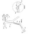
- a Seldinger access technique to the femoral arteryinvolves relatively controlled dilation of a puncture hole to minimize the size of the intruding window through the artery wall, and is a preferred method where the profiles of such delivery systems are sufficiently small. Otherwise, for larger systems a “cut-down” technique is used involving a larger, surgically made access window through the artery wall.
- a local renal agent delivery systemfor contemporaneous use with other retrogradedly delivered medical device systems, such as of the types just described above, would preferably be adapted to allow for such interventional device systems, in particular of the types and dimensions just described, to pass upstream across the renal artery ostia (a) while the agent is being locally delivered into the renal arteries, and (b) while allowing blood to flow downstream across the renal artery ostia, and (c) in an overall cooperating system that allows for Seldinger femoral artery access.
- Each one of these features (a), (b), or (c), or any sub-combination thereof,would provide significant value to patient treatment; a local renal delivery system providing for the combination of all three features is so much the more valuable.
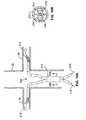
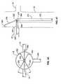
- the renal arteriesextend from respective ostia along the abdominal aorta that are significantly spaced apart from each other circumferentially around the relatively very large aorta. Often, these renal artery ostia are also spaced from each other longitudinally along the aorta with relative superior and inferior locations.
- an appropriate local renal delivery system for such indicationswould preferably be adapted to feed multiple renal arteries perfusing both kidneys.
- mere local delivery of an agent into the natural, physiologic blood flow path of the aorta upstream of the kidneysmay provide some beneficial, localized renal delivery versus other systemic delivery methods, but various undesirable results still arise.
- the high flow aortaimmediately washes much of the delivered agent beyond the intended renal artery ostia. This reduces the amount of agent actually perfusing the renal arteries with reduced efficacy, and thus also produces unwanted loss of the agent into other organs and tissues in the systemic circulation (with highest concentrations directly flowing into downstream circulation).
- tubular local delivery catheterssuch as angiographic catheters, other “end-hole” catheters, or otherwise, may be positioned with their distal agent perfusion ports located within the renal arteries themselves for delivering agents there, such as via a percutaneous translumenal procedure via the femoral arteries (or from other access points such as brachial arteries, etc.).
- angiographic catheterssuch as angiographic catheters, other “end-hole” catheters, or otherwise
- distal agent perfusion portslocated within the renal arteries themselves for delivering agents there, such as via a percutaneous translumenal procedure via the femoral arteries (or from other access points such as brachial arteries, etc.).
- angiographic catheterssuch as angiographic catheters, other “end-hole” catheters, or otherwise
- distal agent perfusion portslocated within the renal arteries themselves for delivering agents there, such as via a percutaneous translumenal procedure via the femoral arteries (or from other access points such as brachi
- kidney functione.g. RCN
- the renal arteries themselvesmay have pre-existing conditions that either prevent the ability to provide the required catheter seating, or that increase the risks associated with such mechanical intrusion.
- the artery wallmay be diseased or stenotic, such as due to atherosclerotic plaque, clot, dissection, or other injury or condition.
- IABPsintra-aortic balloon pumps
- One such techniqueinvolves placing an IABP in the abdominal aorta so that the balloon is situated slightly below (proximal to) the branch arteries.
- the balloonis selectively inflated and deflated in a counterpulsation mode (by reference to the physiologic pressure cycle) so that increased pressure distal to the balloon directs a greater portion of blood flow into principally the branch arteries in the region of their ostia.
- an ability to locally deliver such dye into the renal artery from within the artery itself, such as by seating an angiography catheter there,may also be hindered by the same stenotic condition requiring the dye injection in the first place (as introduced above).
- patientsmay have stent-grafts that may prevent delivery catheter seating.
- the previously disclosed systems and methods summarized immediately abovegenerally lack the ability to effectively deliver agents from within a main artery and locally into substantially only branch arteries extending therefrom while allowing the passage of substantial blood flow and/or other medical devices through the main artery past the branches.
- Thisis in particular the case with previously disclosed renal treatment and diagnostic devices and methods, which do not adequately provide for local delivery of agents into the renal system from a location within the aorta while allowing substantial blood flow continuously downstream past the renal ostia and/or while allowing distal medical device assemblies to be passed retrogradedly across the renal ostia for upstream use.
- agentssuch as protective or therapeutic drugs or radiopaque contrast dye, could be delivered to one or both of the renal arteries in such a manner.
- a local renal drug delivery systemand at least one adjunctive distal interventional device, such as an angiographic or guiding catheter, through a single access site, such as a single femoral arterial puncture.
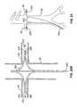
- One aspect of the inventionis a local renal delivery system with two renal delivery members adapted to be positioned within first and second renal arteries and are both coupled to a proximal coupler assembly located externally of the patient's body for material delivery into the two separate arteries via the two delivery members.
- a first renal delivery memberhas a first port that is adapted to be delivered to a first delivery position within a first renal artery via a first corresponding renal ostium located at a first location along an abdominal aorta wall of the abdominal aorta in a patient.
- a second renal delivery memberhas a second port that is adapted to be delivered to a second delivery position within a second renal artery via a second corresponding renal ostium located at a second location along the abdominal aorta wall that is different than the first location.
- the proximal coupler assemblyis adapted to be located externally of the patient when the first and second ports are positioned at the first and second delivery positions, respectively.
- the proximal coupler assemblyis also coupled to the first and second ports so as to deliver material from outside the patient's body via the proximal coupler assembly, through the first and second ports at the first and second delivery positions, respectively, and into the first and second renal arteries, also respectively.
- the systemfurther includes an anchor that is adjustable from a first configuration to a second configuration as follows.
- the anchor in the first configurationis adapted to be delivered to an anchoring position along one of the abdominal aorta or the first renal artery within the patient.
- the anchoris adjustable to the second configuration at the anchoring position and is thus adapted to secure the first renal delivery member with the first port substantially retained at the first delivery position within the first renal artery.
- the anchor in the second configuration at the anchoring positionis also adapted to allow substantial blood flow across the anchoring position.
- the first and second renal delivery assembliestogether comprise a bi-lateral renal delivery system that cooperates with a vascular access system and a percutaneous translumenal interventional device as follows.
- the vascular access systemhas an elongate tubular body with at least one lumen extending between a proximal port and a distal port that is adapted to be positioned within a vessel having translumenal access to a location along the abdominal aorta associated with the first and second renal ostia when the proximal port is located externally of the patient.
- the percutaneous translumenal interventional deviceis adapted to be delivered to an intervention location across the location while the first and second ports are located at the first and second delivery positions, respectively.
- the bilateral renal delivery assembly and percutaneous translumenal interventional deviceare adapted to be delivered percutaneously into the vessel through the vascular access device, and are also adapted to be simultaneously engaged within the vascular access device.
- Another aspect of the inventionis a local renal delivery system with a renal delivery member adapted to be positioned within a renal artery via its ostium along an abdominal aorta wall and that is adapted to be coupled to a proximal coupler assembly located externally of the patient.
- An anchoris also provided to secure the renal delivery member within the renal artery without substantially occluding blood flow across the anchor.
- the renal delivery memberhas a distal port that is adapted to be delivered to a delivery position within the renal artery via a corresponding renal ostium along an abdominal aorta wall.
- the proximal coupler assemblyis adapted to be located externally of the patient when the distal port is positioned at the delivery position.
- the proximal coupler assemblyis also fluidly coupled to the distal port so as to deliver material from outside the patient's body via the proximal coupler assembly, through the distal port at the delivery position and into the renal artery.
- the anchoris adjustable from a first configuration to a second configuration as follows.
- the anchor in the first configurationis adapted to be delivered to an anchoring position along one of the abdominal aorta or the renal artery within the patient.
- the anchoris adjustable from the first configuration to the second configuration at the anchoring position where it is adapted to secure the renal delivery member with the distal port substantially retained at the delivery position within the renal artery.
- the anchor in the second configuration at the anchoring positionis adapted to allow substantial blood flow across the anchoring position.
- the systemfurther includes a second renal delivery member with a second port.
- the second renal delivery memberis adapted to be positioned at least in part within a second renal artery across a second renal ostium having a unique location with respect to the first location along an abdominal aorta wall of an abdominal aorta in the patient with respect, and such that the second port is located at a second position within the renal artery.
- the proximal coupler assemblyis fluidly coupled to each of the first and second ports so as to deliver material from outside the patient's body via the proximal coupler assembly, through the first and second ports at the first and second respective delivery positions and into the first and second renal arteries, respectively.
- Another aspect of the inventionis a local renal delivery system with a vascular access system, a bi-lateral renal delivery assembly, and a percutaneous translumenal interventional device.
- the vascular access systemis adapted to deliver the bi-lateral renal delivery assembly and the percutaneous translumenal interventional device simultaneously into the vasculature such that they can perform their respective functions.
- the vascular access systemhas an elongate tubular body with at least one lumen extending between a proximal port and a distal port that is adapted to be positioned within a vessel when the proximal port is located externally of the patient.
- the bi-lateral renal delivery assemblyincludes first and second renal delivery members with first and second ports, respectively, that are adapted to be delivered to first and second respective delivery positions within first and second renal arteries, respectively, via first and second corresponding renal ostia, respectively, at unique relative locations along an abdominal aorta wall of the patient.
- the percutaneous translumenal interventional deviceis adapted to be delivered to an intervention location across the location while the first and second ports are located at the first and second delivery positions, respectively.
- the bi-lateral renal delivery assemblyis adapted to simultaneously deliver material from an external location relative to the patient and directly into each of first and second renal arteries via first and second ports at the first and second delivery positions, respectively.
- the bilateral renal delivery assembly and percutaneous translumenal medical deviceare adapted to be delivered percutaneously into a vessel having translumenal access to the location through the vascular access device, and are also adapted to be simultaneously engaged within the vascular access device.
- the systemfurther includes an anchor that is adjustable from a first configuration to a second configuration as follows.
- the anchor in the first configurationis adapted to be delivered to an anchoring position along one of the abdominal aorta or the first renal artery within the patient.
- the anchoris adjustable to the second configuration at the anchoring position such that it is adapted to secure the first renal delivery member with the first port substantially retained at the first delivery position within the first renal artery.
- the anchor in the second configuration at the anchoring positionis also constructed so as to allow substantial blood flow across the anchoring position.
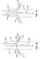
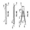
- an elongate bodythat has a proximal end portion and a distal end portion that is adapted to be delivered to a location within the abdominal aorta when the proximal end portion extends externally from the patient.
- the first and second renal delivery membersextend from the distal end portion of the elongate body.
- the first and second renal delivery membersextend distally from the distal end portion of the elongate body in a bifurcated fashion.
- the distal end portion of the elongate bodycomprises first and second ports, and the first and second renal delivery members are moveable relative to the elongate body and are adjustable to extend from the elongate body through the first and second ports, respectively.
- the distal end portion of the elongate bodymay terminate at a distal tip, the first and second ports are located at the distal tip, and the first and second renal delivery members are adjustable to extend distally from the distal tip of the elongate body through the first and second ports, respectively.
- the first and second portsare located at different positions spaced around the circumference of the elongate body proximally of the distal tip, and the first and second renal delivery members are adjustable to extend laterally from the elongate body relative to the longitudinal axis through the first and second ports.
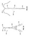
- the first renal delivery memberis substantially fixed and un-adjustable with respect to the elongate body, and the second renal delivery member is adjustable relative to the elongate body.
- a cannulation assemblyis located along the distal end portion of the elongate body with a distal end, a proximal end, a length between the proximal and distal ends along a longitudinal axis, a circumference around the longitudinal axis.
- the first and second renal delivery membersare located along the cannulation assembly at first and second circumferential locations spaced around the circumference.
- the cannulation assemblyis adapted to be positioned at a location within the abdominal aorta associated with the first and second renal ostia.
- the cannulation assemblyis longitudinally collapsible at the location such that the distal and proximal ends of the first and second renal delivery members are brought together with respect to each other.
- the first and second renal delivery membersare biased to extend radially outward from the longitudinal axis at their respective circumferential locations such that the radially extended delivery members are adapted to cannulate the first and second renal arteries via their respective renal ostia along the location, respectively.
- the first and second delivery membersare two of a plurality of more than two renal delivery members.
- Each delivery memberextends laterally from the elongate body with a memory shape such that each terminates at a respective distal tip having a unique position circumferentially about the longitudinal axis.
- the memory shape of each of the plurality of renal delivery membersis adapted to bias the renal delivery member against the abdominal aorta wall at a location along the abdominal aorta corresponding with the first and second renal ostia such that each renal delivery member contacts the wall at a unique lateral location around the circumference of the abdominal aorta wall relative to the other renal delivery members.
- the first and second renal delivery membersare those renal delivery members of the plurality having their unique lateral locations corresponding with the unique locations of the first and second renal ostia, respectively.
- the systemis further adapted to isolate delivery of material from outside the patient to only the first and second renal delivery members cannulated into the first and second renal arteries, respectively.
- the distal tips of multiple ones of the pluralities of renal delivery membersare further adapted to have unique longitudinal locations along the longitudinal axis.
- the first and second renal delivery membersmay be adjustable from a first orientation to a second orientation relative to the distal end portion of the elongate body upon cannulation of the first and second renal arteries as follows. In the first orientation the first and second ports of the first and second renal delivery members are not fluidly coupled to the proximal coupler assembly. In the second orientation the first and second ports of the first and second renal delivery members are fluidly coupled to the proximal coupler assembly.
- one or both of the two renal delivery membersis substantially self-cannulating with respect to the respective renal artery via the corresponding ostium along the abdominal aorta wall such that the member does not require controlled manipulation of its shape within the abdominal aorta for cannulation.
- the self-cannulating renal delivery memberis flow-directed with respect to self-cannulation of the respective renal artery via the corresponding renal ostium along the abdominal aorta wall.
- the self-cannulating renal delivery memberis adapted to passively take a shape within the abdominal aorta that is adapted to self-cannulate the respective renal artery.
- the self-cannulating renal delivery memberis adjustable between a first shape and a second shape that is a memory shape configuration.
- the memory response toward the second shapeis adapted to self-cannulate the respective renal artery.
- one or both of the renal delivery membersis adapted to have a controllable shape and is selectively steerable when positioned within the abdominal aorta so as to selectively cannulate the respective renal artery via its corresponding renal ostium along the abdominal aorta wall.
- a pull-wirehas a distal end portion secured to the renal delivery member at a location so as to be positioned with the renal delivery member within the abdominal aorta, and a proximal end portion of the pull-wire extends proximally therefrom.
- the distal end portion of the pull-wiremanipulates the shape of the steerable renal delivery member such that it may selectively cannulate the respective renal artery via its corresponding renal ostium.
- controllable renal delivery memberhas an elongate body with a stylet passageway that houses a stylet that is moveable relative to the elongate body of the at least one renal delivery member.
- the elongate bodyis adjustable from a first shape to a second shape by relative movement of the stylet between a first stylet position and a second stylet position, respectively, with respect to the elongate body of the at least one renal delivery member.
- the elongate body in the first shapeis adapted to be delivered into the abdominal aorta through a radially confining outer sheath.
- the elongate body in the second shapeis adapted to cannulate the respective renal artery via the corresponding ostium.
- the relative movement of the stylet relative to the renal delivery membercontrols the shape of the renal delivery member.
- the stylethas a shape; and the elongate body of the renal delivery member takes the second shape based upon the shape of the stylet.
- the second shapeis a memory shape condition for the elongate body, and the elongate body is adjusted from the second shape to the first shape by deflection of the elongate body of the at least one renal delivery member from the memory shape condition with the stylet.
- the first renal delivery memberis substantially self-cannulating with respect to the first renal artery via the first ostium
- the second renal delivery memberis not substantially self-cannulating with respect to the second renal artery via the second ostium and has a controllable shape and is steerable so as to controllably cannulate the second renal artery via the second ostium.
- the proximal coupler assemblycomprises first and second proximal couplers as follows.
- the first proximal coupleris fluidly coupled to the first port, and the second proximal coupler is fluidly coupled to the second port.
- the proximal coupler assemblyis a single common coupler that is fluidly coupled to each of the first and second ports via a common fluid passageway.
- the anchoris a renal anchor
- the anchoring positionis located along the first renal artery.
- the anchorincludes a shapeable section of the first delivery member that is adjustable between first and second shapes that correspond with the first and second configurations, respectively, for the anchor.
- the anchoris adjustable from the first shape to the second shape at the anchoring position such that the second shape is biased to radially extend from the longitudinal axis of the first delivery member and is adapted to engage a wall of the first renal artery with sufficient force to secure the first delivery member with the first port at the first delivery position.
- the anchormay include a pull-wire with a distal end portion secured to the renal delivery member at a fixed location corresponding with the shapeable section of the first delivery member, and with a proximal end portion extending proximally from the fixed location.
- the distal end portion of the pull-wiremanipulates the shape of the first renal delivery member from the first shape to the second shape.
- the first renal delivery memberhas a stylet passageway that houses a stylet that is moveable relative to the shapeable section.
- the shapeable sectionis adjustable from the first shape to the second shape by relative movement of the stylet between a first stylet position and a second stylet position, respectively, within the stylet passageway along the shapeable section.
- the stylethas a shape; and the shapeable section is deflectable from the first shape to the second shape by the shape of the stylet.
- the second shapecomprises a memory shape condition for the shapeable section, and the shapeable section is deflectable from the second shape to the first shape by adjusting the relative position of the stylet.
- the first delivery memberincludes proximal and distal sections that are located proximally and distally adjacent to the shapeable section.
- the proximal and distal sectionsare positioned along opposite sides of the renal artery wall.
- the proximal and distal sectionsare positioned along one side of the renal artery wall and the shapeable section is biased against a second opposite side of the renal artery wall.
- the anchorhas a radially extendable member located along the elongate body and that is adjustable between first and second shapes that correspond with the first and second configurations for the anchor as follows.
- the radially extendable member in the second shapeis biased to radially extend from the elongate body relative to the first shape and is adapted to radially engage a wall of the first renal artery with sufficient force to secure the first delivery member within the first renal artery with the first delivery port at the first delivery position.
- the radially extendable membermay extend at least in part between proximal and distal locations that are spaced by a distance along an outer surface of the elongate body and where the radially extendable member is respectively engaged with the elongate body as follows.
- the proximal locationcomprises a port that communicates with a lumen within the elongate body.
- the radially extendable memberhas a length between a proximal portion and a distal portion that is longer than the distance between proximal and distal locations, such that in the first shape the proximal portion of the radially extendable member extends proximally within the port and proximally along the lumen to an internal location such that the length extends between the internal location and the distal location.
- the proximal portion of the radially extendable memberis advanced distally from the internal location to generally correspond with the port at the proximal location such that the length of the radially extendable member extends along a radially extended path between the proximal and distal locations externally of the elongate body within the first renal artery.
- the radially extendable memberextends directly between the proximal and distal locations in the first shape. In another variant, the radially extendable member extends around a circumference of the elongate body between the proximal and distal locations.
- the first shape of the radially extendable memberis wrapped around the elongate body between the proximal and distal locations; the second shape includes an arc that is adapted to engage the wall of the first renal artery over a portion of the circumference of the first renal artery wall.
- the second shapeis a memory shape for the radially extendable member, such that the radially extendable member is adjustable to the first shape within a radially confining outer sheath.
- the radially extendable memberis self-adjustable at the anchoring position from the first shape to the second shape by releasing the radially extendable member from radial confinement.
- the second shapemay be a partial loop shape that extends along an arc between first and second locations around the circumference of the elongate body.
- the anchorfurther comprises a second said radially extendable member with a second shape that is a partial loop shape that extends along an arc along an opposite side of the elongate body. The first and second partial loop shapes are adapted to engage the first renal artery wall on opposite sides with the elongate body located within the first renal artery therebetween.
- the radially extendable memberincludes an inflatable balloon that is adjustable between a deflated configuration and an inflated configuration as follows.
- the deflated configurationcharacterizes the first shape
- the inflated configurationcharacterizes the second shape.
- the second shape characterized by the inflated condition for the balloonmay be a shape that is not round.
- itmay be an oblong lobe with a first diameter that spans across the first renal artery transverse to the longitudinal axis of the first renal artery so as to engage to the first renal artery wall with sufficient force to anchor the first renal delivery member there, but with a second diameter transverse to the first diameter that is less than the diameter of the first renal artery. With this shape the oblong lobe does not completely occlude the first renal artery at the anchoring position.
- the second shapemay also include a plurality of such oblong lobes that are arranged about the circumference of the elongate body in spaced arrangement relative to each other.
- each oblong lobeis adapted to radially engage a unique portion of the first renal artery wall. Blood is thus allowed to flow in the spaces between the adjacent oblong lobes.
- the anchorincludes a plurality of radially extendable members that are located at spaced intervals around the circumference of the elongate body.
- Each radially extendable member in the second shapeis adapted to engage the wall of the first renal artery at a different location around the circumference of the first renal artery relative to the other radially extendable members.
- the systemincludes an anchor that is an aortic anchor deployable at an anchoring position that is located along the abdominal aorta.
- the aortic anchorincludes a shapeable section of the first renal delivery member that is adjustable between first and second shapes that correspond with the first and second configurations, respectively, for the anchor as follows.
- the first delivery memberhas proximal and distal sections located proximally and distally adjacent the shapeable section and that includes the first port.
- the distal sectionincludes the first port and is adapted to be positioned within the first renal artery with the first port at the first delivery location and with the shapeable section located along the anchoring position within the abdominal aorta.
- the proximal sectionextends along a longitudinal axis where it transitions to the shapeable section.
- the shapeable sectionis adjustable from the first shape to the second shape at the anchoring position such that the second shape is biased to radially extend from the longitudinal axis and is adapted to engage a wall of the abdominal aorta at the anchoring position with sufficient force to secure the first delivery member with the first port at the first delivery position.
- the shapeable sectionhas a proximal region and a distal region characterized as follows.
- the proximal regionis radially biased to a first side of the longitudinal axis so as to contact a first side of the abdominal aorta wall
- the distal regionis radially biased to a second side generally opposite the first side of the longitudinal axis so as to contact a second side generally opposite the first side of the abdominal aorta wall.
- the proximal and distal regionscooperate to apply generally opposite forces against the first and second sides of the abdominal aorta wall to thereby anchor the first delivery member at that location.
- the distal regionforms a loop that extends from the proximal region along the first side of the abdominal aorta, arcs across the abdominal aorta to engage the second side of the abdominal aorta, and arcs back across the abdominal aorta from the second side toward the first side.
- the distal sectionextends from the distal region extending across the abdominal aorta and into the first renal artery via the first renal ostium.
- a second anchoris provided that is adjustable from a first configuration to a second configuration as follows.
- the second anchor in its respective first configurationis adapted to be delivered to a second anchoring position along one of either the abdominal aorta or the second renal artery within the patient.
- the second anchor in its respective second configuration at the second anchoring positionis adapted to secure the second renal delivery member with the second port substantially retained at the second delivery position within the second renal artery.
- the second anchor in its respective second configuration at the second anchoring positionis constructed so as to allow substantial blood flow from the abdominal aorta and along the second renal artery to the kidney.
- the first anchoris a renal anchor and the first anchoring position is within the first renal artery
- the second anchoris a renal anchor and the second anchoring position is within the second renal artery.
- the first anchoris an aortic anchor and the first anchoring position is within the abdominal aorta
- the second anchoris an aortic anchor and the second anchoring position is within the abdominal aorta.
- the first anchormay be a renal anchor with the first anchoring position located within the first renal artery
- the second anchoris an aortic anchor with the second anchoring position being located within the abdominal aorta.
- the systemfurther includes a source of material, and the first delivery member is adapted to deliver the material from a location externally of the patient through the first delivery port at the first delivery position and into the first renal artery.
- the source of materialcomprises a fluid agent, and in particular may be a renal protective agent.
- the fluid agentmay be a diuretic, such as in particular Furosemide or Thiazide, or analog or derivative thereof.
- the fluid agentmay be a vasopressor, such as in one particular beneficial example Dopamine, or an analog or derivative thereof.
- the fluid agentmay be a vasodilator or otherwise a vasoactive agent.
- the fluid agentincludes Papaverine, a calcium-channel blocker, Nifedipine, Verapamil, fenoldapam mesylate, a dopamine DA 1 agonist, or analogs or derivatives thereof, or combinations or blends thereof.
- the percutaneous translumenal interventional devicemay be a delivery device to enable interventional therapy or diagnosis, such as a guiding catheter or an angiographic catheter, or may be a direct interventional device such as a recanalization device, e.g. balloon angioplasty, stenting, or atherectomy device, etc.
- the systemis adapted to provide such cooperative operation between these components in particular where the percutaneous translumenal interventional device is between about 4 French and about 8 French.
- the renal vein delivery memberhas a distal port that is adapted to be delivered to a delivery position within a renal vein via its ostium along a vena cava in a patient.
- a proximal coupler assemblyis adapted to be located externally of the patient when the distal port is at the delivery position, and is fluidly coupled to the distal port such that a material may be delivered from outside of the patient through the proximal coupler assembly, through the distal port at the delivery position, and into the renal vein.
- An occlusion memberis adjustable between a first configuration and a second configuration as follows.
- the occlusion member in the first configurationis adapted to be delivered to an occlusion position located toward ostium from the delivery position, such that the distal port and occlusion members are located at the delivery and occlusion positions, respectively.
- the occlusion member in the second configuration at the occlusion positionis adapted to substantially occlude flow from the renal vein and into the vena cava.
- a control systemis provided and is adapted to control cooperative operation of the renal vein delivery assembly and the occlusion member between first and second modes of operation as follows. In the first mode the occlusion member is in the first configuration at the occlusion position and venous blood is allowed to flow from the kidney and along the renal vein and into the vena cava.
- the occlusion memberIn the second mode the occlusion member is in the second configuration at the occlusion position, venous blood is substantially occluded from flowing from the kidney along the renal vein and into the vena cava, and a volume of fluid agent flows through the distal port at the delivery position and into the renal vein at sufficient pressure to provide retrograde flow into the respective kidney coupled to the renal vein.
- a second renal delivery memberis also provided and has a second port that is adapted to be delivered to a second delivery position within a second renal vein via a second ostium having a unique location along the vena cava relative to the first ostium.
- the proximal coupler assemblyis fluidly coupled to each of the first and second ports such that the material may be delivered from outside of the patient through the proximal coupler assembly, through both of the first and second ports at the first and second respective delivery positions, and into the first and second renal veins, respectively.
- a second occlusion memberis adjustable between a first configuration and a second configuration as follows.
- the second occlusion member in the first configurationis adapted to be delivered to a second occlusion position located toward the second ostium from the second delivery position, such that the second port and second occlusion members are located at the second delivery and second occlusion positions, respectively.
- the second occlusion member in the second configuration at the second occlusion positionis adapted to substantially occlude flow from the renal vein and into the vena cava.
- the control systemis further adapted to control cooperative operation of the second renal delivery assembly and the second occlusion member between third and fourth modes of operation as follows.
- the second occlusion memberIn the third mode the second occlusion member is in the first configuration at the second occlusion position and venous blood is allowed to flow from the kidney and along the second renal vein and into the vena cava. In the second mode the second occlusion member is in the second configuration at the second occlusion position, venous blood is substantially occluded from flowing from the kidney along the renal vein and into the vena cava, and a volume of fluid agent flows through the second port at the second delivery position and into the second renal vein with retrograde flow into the respective kidney coupled to the second renal vein.
- the first and third modes of operationare at least in part simultaneous, and the second and fourth modes of operation are at least in part simultaneous.
- Additional aspects of the inventioninclude various methods for treating a renal system in a patient as follows.
- One method aspectincludes: positioning a first port of a first renal delivery member at a first delivery position within a first renal artery via a first corresponding renal ostium located at a first location along an abdominal aorta wall of an abdominal aorta in a patient, and also positioning a second port of a second renal delivery member at a second delivery position within a second renal artery via a second corresponding renal ostium located at a second location along the abdominal aorta wall that is different than the first location.
- This methodalso includes positioning a proximal coupler assembly externally of the patient when the first and second ports are positioned at the first and second delivery positions, respectively. Also included is the step of delivering a material from outside the patient's body via the proximal coupler assembly, through the first and second ports at the first and second delivery positions, respectively, and into the first and second renal arteries, also respectively.
- Another method aspectincludes: delivering a distal port of a renal delivery member to a delivery position within a renal artery via a corresponding renal ostium along an abdominal aorta wall, positioning a proximal coupler assembly externally of the patient when the distal port is positioned at the delivery position, delivering an anchor in a first configuration to an anchoring position along one of the abdominal aorta or the renal artery within the patient, and adjusting the anchor at the anchoring position from the first configuration to a second configuration that secures the renal delivery member with the distal port substantially retained at the delivery position within the renal artery.
- this methodalso includes allowing substantial blood flow across the anchoring position when the anchor is in the second configuration at the anchoring position, and delivering material from outside the patient's body via the proximal coupler assembly, through the distal port at the delivery position and into the renal artery.
- Another method aspect of the inventionincludes: positioning a distal port of a tubular body of a vascular access system within a vessel having transvascular access to a location along an abdominal aorta associated with first and second renal ostia when a proximal port of the tubular body is located externally of the patient. Another step is introducing first and second renal delivery members of a bi-lateral local renal deliver assembly into the vessel through the tubular body. Another step is introducing a percutaneous translumenal interventional device into the vessel through the tubular body. A further step includes delivering first and second ports of the first and second renal delivery members, respectively, to first and second respective delivery positions within first and second renal arteries, respectively, via the first and second renal ostia, also respectively.
- Another stepis delivering a distal end portion of the percutaneous translumenal interventional device to an intervention location across the location while the first and second ports are located at the first and second delivery positions, respectively.
- An additional stepincludes simultaneously delivering material from an external location relative to the patient and directly into each of first and second renal arteries via the first and second ports at the first and second delivery positions, respectively. Accordingly, the bi-lateral renal delivery assembly and a proximal end portion of the percutaneous translumenal interventional device are simultaneously engaged within the tubular body of the vascular access assembly when the first and second ports are at the first and second delivery positions and the distal end portion of the percutaneous translumenal interventional device is at the intervention location.
- Another method aspect according to the inventionincludes a method for preparing a bi-lateral renal delivery system for use in treating a patient as follows. This method includes: introducing first and second renal delivery members of a bi-lateral local renal delivery assembly into a tubular body of a vascular access system, and introducing a percutaneous translumenal interventional device into the tubular body.
- the various components used in these method stepsare further characterized as follows.
- the bi-lateral renal delivery assembly and the percutaneous translumenal interventional deviceare simultaneously engaged within the tubular body of the vascular access assembly.
- the first and second renal delivery membershave first and second ports, respectively, that are adapted to be delivered to first and second respective delivery positions within first and second renal arteries, respectively, via first and second renal ostia, also respectively, having unique locations along the abdominal aortic wall.
- the percutaneous translumenal interventional devicehas a distal end portion that is adapted to be delivered to an intervention location across a location along the abdominal aorta associated with the first and second renal ostia while the first and second ports are located at the first and second delivery positions, respectively.
- the first and second renal delivery membersare coupled to a proximal coupler assembly that is adapted to deliver material from an external location relative to the patient and to the first and second ports so as to deliver the material directly into each of first and second renal arteries via the first and second ports at the first and second delivery positions, respectively.
- the tubular body of the vascular access systemhas a distal port that is adapted to be positioned within a vessel having transvascular access to the location along the abdominal aorta when a proximal port of the tubular body is located externally of the patient.
- Another method aspect of the inventionis a method for treating a renal system in a patient via a renal vein as follows.
- This methodincludes: delivering a distal port of a renal delivery member to a delivery position within a renal vein via its ostium along a vena cava in a patient, and positioning a proximal coupler assembly externally of the patient when the distal port is at the delivery position.
- the methodalso includes fluidly coupling the proximal coupler assembly to the distal port such that a material may be delivered from outside of the patient through the proximal coupler assembly, through the distal port at the delivery position, and into the renal vein.
- Another stepis delivering an occlusion member in a first configuration to an occlusion position located toward ostium from the delivery position, such that the distal port and occlusion members are located at the delivery and occlusion positions, respectively.
- a further stepincludes adjusting the occlusion member at the occlusion position from the first configuration to a second configuration so as to substantially occlude flow from the renal vein and into the vena cava.
- this methodalso includes controlling co-operative operation of the renal delivery assembly and the occlusion member between first and second modes of operation as follows. In the first mode the occlusion member is in the first configuration at the occlusion position and venous blood is allowed to flow from the kidney and along the renal vein and into the vena cava.
- the occlusion memberIn the second mode the occlusion member is in the second configuration at the occlusion position, venous blood is substantially occluded from flowing from the kidney along the renal vein and into the vena cava, and a volume of fluid agent flows through the distal port at the delivery position and into the renal vein at sufficient pressure to provide retrograde flow into the respective kidney coupled to the renal vein.
- Another method aspect of the inventionincludes flow directing a local renal delivery member from a location within an abdominal aorta and into a renal artery via its renal ostium along the aorta wall.
- two renal delivery membersare flow directed into each of two separate renal ostia, such that bi-lateral local renal delivery may be performed.
- Another method aspect of the inventionincludes cannulating a plurality of x branch lumens from a main lumen or body space by delivering y delivery members to the main lumen or body space that are adapted to be positioned at y unique locations along the main lumen or body space, such that x ones of the y delivery members are located to correspond with the x branch lumens so as to cannulate those branch lumens, wherein x and y are integers and y is greater than x.
- Another aspect of the inventionis a method for treating a renal system in a patient that includes: positioning an introducer sheath within an abdominal aorta at a location associated with first and second renal artery ostia associated with first and second renal arteries that perfuse first and second kidneys in the patient, and delivering a bi-lateral renal delivery assembly in a first configuration under radial confinement through the introducer sheath and to a first position along the location.
- This methodfurther includes withdrawing the introducer with respect to the bi-lateral renal delivery assembly so as to remove the radial confinement.
- the methodfurther includes allowing first and second bifurcating delivery members to self-expand apart from each other and radially against an abdominal aorta wall at the location with shape memory recovery force to a second configuration.
- a further mode of this aspectincludes modifying the position of the self-expanded renal delivery assembly so as to self-cannulate at least one of the delivery members into at least one of the renal arteries via its corresponding ostium along the abdominal aorta wall.
- the methodfurther includes torquing the renal delivery assembly in the second configuration.
- the methodfurther includes modifying the longitudinal position of the renal delivery assembly in the second configuration.
- a bi-lateral local renal delivery assemblyis delivered to a location within an abdominal aorta corresponding with first and second renal ostium along an abdominal aorta wall of the patient.
- a percutaneous translumenal interventional deviceis delivered to an intervention location across the location corresponding with the renal ostia.
- a first delivery member of the bilateral local renal delivery assemblyis positioned in a first renal artery via a first ostium along the abdominal aorta wall, whereas a second delivery member of the bilateral local renal delivery assembly is positioned within a second renal artery via a second ostium along the abdominal aorta wall.
- the bi-lateral local renal delivery assembly and percutaneous translumenal interventional deviceare inserted into the patient's vasculature through a common vascular access site.
- a further mode of this aspectincludes injecting radiocontrast dye into the patient at the intervention location with the percutaneous translumenal device.
- Another aspect of the inventionis a system for providing local renal therapy in a patient that includes an introducer sheath with a proximal end portion and a distal end portion that is adapted to be positioned at a location within an abdominal aorta associated with first and second renal ostia of first and second renal arteries, respectively, while the proximal end portion extends externally from the patient, and also with an introducer lumen extending between a proximal port located along the proximal end portion and a distal port located along the distal end portion.
- This systemfurther includes a local injection assembly with an injection port assembly that is adapted to be delivered to the location through the introducer lumen and through the distal port in a first condition.
- the local injection assemblyis adapted to be adjusted at the location from the first condition to a second condition that is advanced externally through the distal port at the location.
- the local injection assemblyIn the second condition at the location the local injection assembly is adapted to be fluidly coupled to a source of fluid agent located externally from the patient.
- the local injection assemblyIn the second condition at the location the local injection assembly is also adapted to position the injection port assembly so as to inject a volume of fluid agent substantially bilaterally into each of the two renal arteries.
- a sensing mechanismthat is adapted to sense a position of at least one of the injection port assembly or the distal port relative to at least one of the renal ostia without use of fluoroscopic or X-ray imaging.
- At least one markeris provided at a location that is adapted to indicate the location of at least one of the injection port assembly or the distal port with respect to a non-fluoroscopic sensor assembly located externally of the location.
- a marker assemblyis located along the distal end portion of the introducer sheath and is adapted to indicate the relative location of the distal port within the location relative to at least one renal ostium.
- the local injection assemblyincludes first and second injection ports that are adapted to be delivered to first and second positions such that the volume of fluid agent is injected substantially into the first and second renal arteries via the first and second injection ports, respectively, at the first and second positions, also respectively.
- First and second markersare positioned relative to the first and second injection ports, respectively, so as to indicate the relative position of the injection ports relative to the first and second positions, also respectively.
- the local injection assemblyincludes first and second injection members, and the first and second injection ports are located along the first and second injection members, respectively.
- the first and second markersare located at first and second locations along the first and second injection members relative to the first and second injection ports.
- a sensor assemblyis provided that is adapted to cooperate with at least one of the local injection assembly or the distal port of the introducer sheath such that the sensor assembly is adapted to be positioned within the location and to sense a parameter indicative of the relative position of the local injection assembly or distal port relative to the renal ostia at the location.
- a sensoris located along the distal end portion of the introducer sheath and is adapted to sense a parameter that is indicative of a relative location of the distal port relative to at least one renal ostium.
- At least one sensoris located relative to the injection port assembly so as to indicate the relative position of the injection port assembly.
- the local injection assemblyincludes first and second injection ports that are adapted to be delivered to first and second positions such that the volume of fluid agent is injected substantially into the first and second renal arteries via the first and second injection ports, respectively, at the first and second positions, also respectively.
- First and second sensorsare positioned relative to the first and second injection ports, respectively, so as to indicate the relative position of the injection ports relative to the first and second positions, also respectively.
- the local injection assemblyincludes first and second injection members, and the first and second injection ports are located along the first and second injection members, respectively. Further to this feature, the first and second sensors are located at first and second locations along the first and second injection members relative to the first and second injection ports.
- suchmay include an ultrasound sensor, a Doppler ultrasound sensor, an optical sensor, a pressure sensor, a flow velocity sensor, a flow rate sensor, or a chemical sensor, or combinations thereof.
- a monitoring assemblymay also be provided for monitoring the sensed parameters externally of the patient.
- Another aspect of the inventionis a method for providing local renal therapy in a patient that includes in one regard delivering a distal end portion of an introducer sheath to a location within an abdominal aorta associated with first and second renal ostia of first and second renal arteries, respectively, while a proximal end portion of the introducer sheath extends externally from the patient, and also such that an introducer lumen within the introducer sheath extends between a proximal port located along the proximal end portion and a distal port located along the distal end portion at the location.
- a local injection assembly with an injection port assemblyis delivered to the location through the introducer lumen and through the distal port in a first condition.
- the local injection assemblyis adjusted at the location from the first condition to a second condition that is advanced externally through the distal port at the location.
- the local injection assembly in the second condition at the locationis fluidly coupled to a source of fluid agent located externally from the patient.
- the injection port assemblyis positioned so as to inject a volume of fluid agent from the source substantially bilaterally into each of the two renal arteries.
- a parameter indicative of a position of at least one of the injection port assembly or the distal port relative to at least one of the renal ostiais sensed without use of fluoroscopic or X-ray imaging.
- non-fluoroscopic positioning sensing the positionmay be accomplished an ultrasound sensor, a Doppler ultrasound sensor, by sensing an optical parameter with an optical sensor, by sensing a pressure parameter with a pressure sensor, by sensing a velocity of blood flow with a flow velocity sensor, by sensing a blood flow rate with a flow rate sensor, or by sensing a chemical parameter of blood with a chemical sensor, or by use of a combination of these modalities.
- FIG. 1illustrates the distal section of a fluid agent delivery catheter with a preformed shape to anchor in an artery according to the present invention.
- FIG. 2Aillustrates a method of deploying a preformed shaped catheter introduced in a sheath.
- FIG. 2Billustrates the intermediate retraction of the sheath shown in FIG. 2A .
- FIG. 2Cillustrates further retraction of the sheath shown in FIG. 2A .
- FIG. 3illustrates a fluid delivery catheter extending into a branch artery with a high flexibility deflectable section.
- FIG. 4Aillustrates a method of inserting a catheter with a deflectable section as shown in FIG. 3 using a stylet.
- FIG. 4Billustrates a method of deploying a catheter with a deflectable section as shown in FIG. 3 using a stylet
- FIG. 5illustrates another embodiment of a fluid delivery catheter with a preformed anchoring shape.
- FIG. 6Aillustrates a first step for deploying a preformed shape catheter as shown in FIG. 5 with a stylet.
- FIG. 6Billustrates another step for deploying a preformed shape catheter as shown in FIG. 5 with a stylet.
- FIG. 6Cillustrates a further step for deploying a preformed shape catheter as shown in FIG. 5 with a stylet.
- FIG. 6Dillustrates a preformed shape catheter, deployed with a stylet, in an anchoring shape as shown in FIG. 5 .
- FIG. 7Aillustrates a multilumen catheter using a flexible reinforcing element as an anchoring device.
- FIG. 7Billustrates distal motion of the reinforcing element forming an expanded loop.
- FIG. 7Cillustrates a cross-sectional view of the catheter shown in FIG. 7B inserted in a body vessel.
- FIG. 8Aillustrates another embodiment of the catheter shown in FIG. 7A where the reinforcing element loops around the catheter in a helical configuration.
- FIG. 8Billustrates the loop formed in FIG. 8A when the reinforcing element is extended.
- FIG. 8Cillustrates a section view of the catheter shown in FIG. 8B symmetrically anchored to the wall of an artery.
- FIG. 9is another embodiment of the device shown in FIG. 7A with two or more reinforcing elements for anchors.
- FIG. 10illustrates a multilumen catheter shown in FIG. 9 with four reinforcing elements, inserted and anchored in a branch artery.
- FIG. 11Aillustrates an anchoring catheter with a reinforcing element to anchor near the distal end.
- FIG. 11Billustrates the anchoring catheter shown in FIG. 11A with the reinforcing element deployed.
- FIG. 12Aillustrates a method of constructing an anchoring catheter to form loops that provide an anchoring force as shown previously in FIG. 10 .
- FIG. 12Billustrates the anchoring catheter in FIG. 12A with loops deployed to bow outward.
- FIG. 13Aillustrates another anchoring catheter using two loops of shape retaining material.
- FIG. 13Billustrates the anchoring catheter shown in FIG. 13A restricted in a sheath.
- FIG. 13Cillustrates the anchoring catheter shown in FIG. 13A deployed in a blood vessel.
- FIG. 14Aillustrates a side view of multilumen catheter with an asymmetrical, inflatable anchoring member according to the present invention.
- FIG. 14Bis a cross sectional view of the catheter in FIG. 14A with the inflatable anchoring member folded in a sheath.
- FIG. 14Cis a cross sectional view of the catheter in FIG. 14A deployed in a blood vessel.
- FIG. 15Aillustrates a multilumen catheter with a multi-lobed, symmetrical, inflatable anchoring member.
- FIG. 15Bis a cross sectional view of the catheter in FIG. 15A with the inflatable anchoring member folded in a sheath.
- FIG. 15Cis a cross sectional view of the catheter in FIG. 15A deployed in a blood vessel.
- FIG. 16illustrates the distal section of an anchoring renal catheter with a preformed compound shape.
- FIG. 17illustrates another embodiment of the renal catheter shown in FIG. 16 where the compound shape comprises a 270-degree loop.
- FIG. 18Aillustrates a bifurcated renal catheter with distal anchoring sections manipulated by control wires.
- FIG. 18Billustrates a cross sectional view of the catheter shown in 18 A taken along the lines 18 B- 18 B.
- FIG. 19illustrates a preformed bifurcated catheter with distal sections having opposite preformed 90-degree loop shapes for anchoring.
- FIG. 20illustrates a variation of a preformed bifurcated catheter where one distal section is similar to that shown in FIG. 17 and the second distal section similar to that shown in FIG. 10 .
- FIG. 21illustrates the cross section of bifurcated catheter as shown in FIG. 20 taken along the lines 21 - 21 .
- FIG. 22Aillustrates a plan view of a multilumen catheter with a longitudinal slit near the distal end.
- FIG. 22Billustrates a cross section view of FIG. 22A taken along the lines 22 B- 22 B.
- FIG. 22Cillustrates a perforating crosscut forming hinges of the catheter shown in FIG. 22A with the hinges in the partly open position.
- FIG. 22Dillustrates the catheter shown in FIG. 22A inserted in a main artery with hinges flexed in the fully open position.
- FIG. 23illustrates two independent micro catheters each placed directly into a renal artery.
- FIG. 24illustrates a flow-guided catheter with flexible renal sub catheters and an inflatable member in an inflated state.
- FIG. 25illustrates the flow-guided catheter shown in FIG. 24 with the inflatable member in a deflated state.
- FIG. 26illustrates a flow-guided catheter for use with a brachial approach from above the renal arteries.
- FIG. 27is a flow-guided catheter for use with a brachial approach from above with an inflatable member.
- FIG. 28illustrates a truncated cone flow diverter that may be used adjunctively with flow-guided catheters using a brachial approach.
- FIG. 29illustrates a low profile flow-guided catheter using a brachial approach.
- FIG. 30illustrates the flow-guided catheter shown in FIG. 29 with sub catheters equipped with distal tip inflatable members.
- FIG. 31illustrates independent low profile flow guided sub-catheters using a brachial approach.
- FIG. 32illustrates the independent sub-catheters shown in FIG. 31 with distal tip inflatable members.
- FIG. 33illustrates the distal end of a bifurcated renal catheter.
- FIG. 34illustrates the proximal end of the bifurcated catheter shown in FIG. 33 with a hub assembly and controls for pull wires.
- FIG. 35illustrates the non-supported, pre-formed distal extensions of a bifurcated
- FIG. 35Aillustrates the non-supported, pre-formed distal extensions of an alternative embodiment of a bifurcated renal infusion catheter.
- FIG. 35Billustrates the non-supported, pre-formed distal extensions of an alternative embodiment of a bifurcated renal infusion catheter.
- FIG. 35Cillustrates the non-supported, pre-formed distal extensions of an alternative embodiment of a bifurcated renal infusion catheter.
- FIG. 36is a stylized illustration of the bifurcated catheter of FIG. 35 with the distal extensions positioned in the renal arteries.
- FIG. 37is another bifurcated renal infusion catheter with pre-formed distal extensions.
- FIG. 38is the bifurcated catheter as illustrated in FIG. 37 with offset distal extensions.
- FIG. 39is another embodiment of a bifurcated catheter as shown in FIG. 37 where a plurality of distal extensions are offset and located on one side.
- FIG. 40is a bifurcated catheter with a moveable distal extension controlled by a guide wire.
- FIG. 41is another bifurcated catheter as shown in FIG. 40 where both moveable distal extensions may be manipulated independently by guide wire.
- FIG. 42illustrates a bifurcated infusion catheter with four preformed distal extensions.
- FIG. 43is a stylized illustration of the catheter as shown in FIG. 42 with two extensions positioned in renal arteries.
- FIG. 44is a stylized illustration of the catheter as shown in FIG. 42 with four extensions positioned in renal arteries.
- FIG. 45illustrates another beneficial embodiment of a renal infusion catheter with multiple preformed distal extensions.
- FIG. 46illustrates a schematic cross section of an aorta at the intersection of the renal arteries with a multiple distal extension catheter deployed.
- FIG. 47is a stylized illustration of an infusion catheter with multiple pivoting distal extensions.
- FIG. 48Aillustrates a step in constructing a multiple distal extension catheter according to the present invention.
- FIG. 48Billustrates another step in constructing a multiple distal extension catheter.
- FIG. 48Cillustrates a further step in constructing a multiple distal extension catheter.
- FIG. 48Dillustrates another step in constructing a multiple distal extension catheter.
- FIG. 48Eillustrates a further step in constructing a multiple distal extension catheter.
- FIG. 48Fillustrates another step in constructing a multiple distal extension catheter.
- FIG. 48Gillustrates a further step in constructing a multiple distal extension catheter.
- FIG. 49is an illustration of a drain catheter system for use in the venous system according to the present invention.
- FIG. 50is a detailed view of the distal tip of the drain catheter system shown in FIG. 49 and deployed in a renal vein.
- FIG. 51illustrates another embodiment of a distal tip for the drain catheter system shown in FIG. 50 with an expandable mesh deployed in a renal vein.
- FIG. 52illustrates a detailed view of another embodiment of a distal tip for the drain catheter system shown in FIG. 50 combining the embodiments shown in FIG. 50 and FIG. 51 .
- FIG. 53illustrates a typical reversible roller pump at the proximal end of the drain catheter shown in FIG. 49 .
- FIG. 54illustrates a proximal coupler system for delivering aortic devices adjunctively with a catheter.
- FIG. 55illustrates a cross-sectional view of the proximal coupler system as shown in FIG. 54 .
- FIG. 56Aillustrates a proximal coupler assembly as shown in FIG. 54 coupled to a local fluid delivery system.
- FIG. 56Billustrates a proximal coupler assembly as shown in FIG. 56A with the local fluid delivery system advanced in an introducer sheath.
- FIG. 57illustrates a proximal coupler assembly as shown in FIG. 54 through 56B with a fluid infusion device deployed in the renal arteries and a catheter simultaneously deployed in the aorta.
- FIG. 58illustrates a renal therapy system with an introducer sheath system, a vessel dilator, a fluid delivery system and a bifurcated catheter.
- FIG. 59is a stylized illustration of a double Y assembly with two local fluid delivery systems and an intervention catheter in an aorta system.
- the present inventionis principally related to selective bi-lateral renal delivery systems and methods. Accordingly, the present invention is thus related to, and the present description is to be read in combination with, various aspects of the subject matter disclosed in the following prior filed, co-pending U.S. patent applications that are commonly owned with the present application (to the extent such disclosures are readily considered in conjunction with the present disclosure, as would be apparent to one of ordinary skill): Ser. No. 09/229,390 to Keren et al., filed Jan. 11, 1999; Ser. No. 09/562,493 to Keren et al., filed May 1, 2000; and Ser. No. 09/724,691 to Kesten et al., filed Nov. 28, 2000. The disclosures of these prior patent applications are herein incorporated in their entirety by reference thereto.
- the inventionis also related to, and the present description should be considered in conjunction with, certain aspects of the subject matter disclosed in the following Published International Patent Applications (to the extent such published disclosures are readily considered in conjunction with the present disclosure as would be apparent to one of ordinary skill): WO 00/41612 to Libra Medical Systems, published Jul. 20, 2000; and WO 01/83016 to Libra Medical Systems, published Nov. 8, 2001.
- the disclosures of these Published International Patent Applicationsare also herein incorporated in their entirety by reference thereto.
- FIG. 1 through FIG. 59for illustrative purposes the present invention is embodied in the apparatus generally shown in FIG. 1 through FIG. 59 . It will be appreciated that the apparatus may vary as to configuration and as to details of the parts, and that the method may vary as to the specific steps and sequence, without departing from the basic concepts as disclosed herein.
- proximalshould be understood to mean locations on a system or device relatively closer to the operator during use
- distalshould be understood to mean locations relatively further away from the operator during use of a system or device.
- the disclosed material delivery systemswill include a fluid delivery assembly, a proximal coupler assembly and one or more elongated bodies, such as catheters.
- elongated bodiesmay contain one or more delivery lumens and generally consist of a proximal region, a mid-distal region, and a distal tip region or regions in the case of multi-tipped embodiments.
- the distal tip regionwill typically have means for anchoring and means for delivering a material such as a fluid agent.
- Radiopaque markers or other devicesmay be coupled to the specific regions of the elongated body to assist introduction and positioning.
- the material delivery systemis intended to be placed into position by a physician, typically either an interventionalist (cardiologist or radiologist) or an intensivist, a physician who specializes in the treatment of intensive-care patients.
- a physiciantypically either an interventionalist (cardiologist or radiologist) or an intensivist, a physician who specializes in the treatment of intensive-care patients.
- the physicianwill gain access to a femoral artery in the patient's groin, typically using a Seldinger technique of percutaneous vessel access or other conventional method.
- FIG. 1an embodiment of the distal section of an anchoring material delivery catheter 10 with a preformed shape to anchor in an artery 12 to prevent movement during medical procedures is generally shown.
- Material delivery cathetersmay move during medical procedures due to blood flow, body movement and movement of interventional catheters. It is highly beneficial that the distal portion of a catheter remain stationary within the branch blood vessel and deliver therapeutic agent throughout the procedure.
- the proximal shaftwill play a significant role in the maintenance of catheter position within the patient anatomy. The mechanical characteristics of the proximal shaft region will influence the magnitude of the “anchoring” forces required on the wall of the main or branch artery by the apparatus discussed below.
- the proximal shaft section of the catheterwill require greater stiffness and column strength to withstand the forces imparted on the catheter by blood flow in the main vessel and possible patient repositioning or movement that can occur throughout the course of treatment.
- the pre-formed shape in this embodimentcomprises a near distal section 14 with a memory shape defined by R 1 and an adjacent second section 16 with memory shape defined by radius R 2 .
- Radius R 1 and radius R 2are biased in the opposite direction so catheter 10 forms a generally S shape and exerts opposite spring forces in the direction of arrows 18 against the walls of artery 12 when section 14 and section 16 are in their natural state.
- the wall of the proximal shaft regionincludes a stainless-steel braid, coil or multiple independent longitudinal wire inclusions to increase column strength and flexural rigidity.
- the proximal shaft regionis preferably constructed of a higher durometer polymeric material such as 60D to 70D polyurethane or a poly-ether-block-amide copolymer such as PEBAX.
- FIG. 2A through FIG. 2Cillustrates sequential steps in a method of deploying a pre-formed catheter 10 introduced in a radially confining sheath 22 .
- Distal end 25 of the catheter 10is released from sheath 22 by moving sheath 22 proximally as shown by directional arrow 24 or alternatively by advancing catheter 10 distally through the sheath as shown by directional arrow 26 .
- FIG. 2Billustrates the position of the pre-formed catheter 10 with section 14 , formed with memory shape defined radius R 1 , exposed from sheath 22 .
- FIG. 2Cillustrates the position of the pre-formed catheter 10 with second section 16 formed with radius R 2 exposed.
- FIG. 3 through FIG. 4Billustrate an anchoring material delivery catheter 30 extending through a main artery 32 and into a branch artery 3 with a shapeable section 36 deployed to form an S configuration defined by radius R 1 and radius R 2 .
- Radius R 1is formed when shapeable section 36 is deformed by a guide wire (shown in FIG. 4A and FIG. 4B ) or other deployment means.
- Radius R 2is formed by the contact of the distal end 38 on the wall of branch artery 34 .
- the “S” shape of catheter 30exerts anchoring force 40 proximal of the deflectable section 36 and anchoring force 42 distal of the shapeable section 36 .
- FIG. 4A and FIG. 4Billustrate a method of anchoring catheter 30 with a shapeable section 36 .
- Pull wire 44is attached to an inner lumen wall of shapeable section 36 at approximately median position 46 and extends to a control point at the proximal end of catheter 30 (not shown).
- proximal segment 48 of shapeable section 36takes a shape defined by radius R 1 as shown in FIG. 4B .
- Distal section 50 of shapeable section 36takes a shape defined by radius R 2 (shown in FIG. 3 ) by contact of distal end 38 of catheter to the artery wall 34 .
- Control over anchor force 40 and anchor force 42 exerted on artery wall 34may be achieved by monitoring the tensile force exerted on pull wire 44 .
- FIG. 5another embodiment of an anchoring material delivery catheter 52 with an anchoring memory shape is generally shown.
- catheter 52is deployed in artery 12 where section 54 is configured with radius R 1 , section 56 is configured with radius R 2 oriented opposite from R 1 , section 58 with radius R 3 oriented towards R 2 and section 60 with radius R 4 oriented opposite from R 3 .
- the orientation of radii R 1 through R 4create an anchor shape that exerts outward anchoring forces 62 and 64 and anchors catheter 52 in artery 12 when sections 54 , 56 , 58 and 60 assume their natural memory shape.
- FIG. 6A through FIG. 6Dillustrate a method of anchoring a pre-formed shaped material delivery member 52 as shown in FIG. 5 .
- Stiff mandrel 66is inserted in catheter 52 to position memory shaped sections 54 , 56 , 58 , and 60 in a straightened configuration.
- stiff mandrel 66has been retracted proximally as shown by arrow 68 to allow section 54 to assume a memory shape defined by radius R 1 . Note that radius R 1 may vary during deployment as the catheter 52 is positioned.
- stiff mandrel 66has been retracted proximally past section 58 and section 56 assumes memory shape defined by radius R 2 and section 58 assumes memory shape with radius R 4
- stiff mandrel 66has been retracted proximally past section 60 with radius R 4 and delivery member 52 assumes an anchoring shape as illustrated in FIG. 5 .
- FIG. 7A through FIG. 7Cillustrate another embodiment of an anchoring multilumen delivery catheter 70 with a flexible reinforcing element 72 located in reinforcing element lumen 74 according to the present invention.
- reinforcing element 72exits the reinforcing element lumen 74 through first opening 76 and reenters the reinforcing element lumen 74 proximal of first opening 76 at second opening 78 .
- Reinforcing element 72is anchored in reinforcing element lumen 74 distal of second opening 78 at position 80 .
- FIG. 7Billustrates distal motion 82 of reinforcing element 72 in reinforcing element lumen 74 causing reinforcing element 72 to form an expanded loop 84 defined by radius R 1 outside of catheter 70 and between first opening 76 and second opening 78 .
- FIG. 7Cillustrates a section view of delivery member 70 shown in FIG. 7B asymmetrically anchored to a wall of artery 12 by force 86 exerted by expanded loop 84 and by force 88 exerted by the body of catheter 70 .
- FIG. 8A and FIG. 8Billustrate another embodiment of an anchoring multilumen delivery member 70 where reinforcing element 72 exits first opening 76 and loops around delivery member 70 in a helical configuration before entering second opening 78 .
- FIG. 8Billustrates the delivery member 70 in FIG. 8A with loop 90 formed around catheter 70 when reinforcing element 72 is pushed in direction 82 .
- FIG. 8Cillustrates a sectional view of delivery member 70 shown in FIG. 8B symmetrically anchored to a wall of artery 12 by forces in the direction of arrow 92 that are exerted on the inner wall circumference artery 12 by expanded loop 90 .
- FIG. 9Is another embodiment of an anchoring delivery catheter shown in FIG. 7A with two or more reinforcing elements 72 in a multilumen catheter 100 with a first opening 76 and corresponding second opening 78 for each reinforcing element 72 .
- Three reinforcing elements 72are illustrated in FIG. 9 with phantom lines of the reinforcing element lumens 74 omitted for clarity.
- FIG. 10illustrates a multilumen catheter 102 , similar to catheter 100 in FIG. 9 , with four reinforcing elements 72 inserted and anchored in a branch artery 34 of a main artery 32 .
- reinforcing elements 72When reinforcing elements 72 are extended, they bow outward into loops 104 which exert an anchoring force 106 against the inner wall of branch artery 34 .
- FIG. 11A and FIG. 11Billustrate an embodiment of an anchoring delivery catheter where reinforcing strut 110 is anchored near the distal end 112 of a catheter 114 and is attached to the distal end 116 of sheath 118 which encloses the catheter 114 proximal of distal end 112 .
- sheath 118is advanced as shown by arrow 120 or alternatively, catheter 114 is retracted as shown by arrow 122 .
- Reinforcing strut 110bows outward as loop 124 which anchors the catheter 114 in similar to the anchor previously shown in FIG. 7C .
- FIG. 12A and FIG. 12Billustrate a cut section view of an anchoring delivery catheter where catheter 130 is encased in flexible sheath 132 and anchored to sheath 132 at the distal end 134 near the distal end of catheter 130 .
- Slits 136are made in pairs lengthwise near the distal end of sheath 132 to form two or more struts 138 .
- a pair of struts 138is depicted in the embodiment shown in FIG. 12A and FIG. 12B .
- sheath 132is advanced in a distal direction shown by arrow 140 or alternatively, or in combination, catheter 130 is retracted in a proximal direction as shown by arrow 142 .
- Sheath struts 138bow outward to form loops 144 which anchor catheter 130 against a vessel wall as shown previously in FIG. 10 .
- FIG. 13A through FIG. 13Cillustrates an anchoring delivery catheter where two or more loops 150 of shape retaining material, such as nickel titanium wire, are attached near the distal end of catheter 152 so the coupling 154 of metal loops are proximal of the apex 156 of loops 150 .
- Loops 150are configured to bias the apex 156 away from the surface of catheter 152 when loops 150 are in their free state.
- FIG. 13Billustrates catheter 152 shown in FIG. 13A with loops 150 attached that are encased in a radially confining sheath 158 , such as an introducer sheath, which compresses the apex 156 of loops 150 near the surface of catheter 152 within sheath 158 .
- a radially confining sheath 158such as an introducer sheath
- FIG. 13Cillustrates catheter 152 shown in FIG. 13A inserted in artery 12 with sheath 158 retracted in the proximal direction shown by arrow 160 .
- Loops 150flex outwardly and loop apex 156 exerts outward anchoring force 162 against the inner wall of artery 12 .
- sheath 158is advanced over catheter 152 to collapse loops 150 to permit the removal of catheter 152 .
- FIG. 14A through FIG. 14Cillustrates the distal section of another embodiment of an anchoring multilumen catheter 164 according to the present invention.
- Catheter 164has an inflation lumen 166 fluidly connected to asymmetrical inflatable member 168 , with an oblong lobe shape, shown in an inflated state.
- FIG. 14Billustrates a cross section of catheter 164 encased in sheath 170 with asymmetrical inflatable member 168 in a deflated state and folded around catheter 164 .
- FIG. 14Cillustrates a cross section of catheter 164 inserted in artery 12 with asymmetrical inflatable member 168 in an inflated state and exerting anchoring force 172 and anchoring force 174 against the inner wall of artery 12 .
- the cross section of asymmetrical inflatable member 168is a lobe shape to contact inner wall of artery 12 in one location when inflated and simultaneously allow free area 178 for blood flow in artery 12 .
- FIG. 15A through FIG. 15Cillustrate another embodiment of an anchoring multilumen catheter 164 with inflation lumen 166 fluidly connected to a symmetrical inflatable member 180 generally comprising two or more symmetrically positioned lobes 182 .
- inflatable member 180has 4 symmetrical lobes 182 .
- FIG. 15Billustrates a cross section of catheter 164 encased in a radial confinement sheath 170 with lobes 182 of symmetrical inflatable member 168 in a deflated state and folded around catheter 164 .
- FIG. 15Cillustrates a cross section of catheter 164 inserted in artery 12 with radial confinement sheath 170 shown in FIG. 15B removed and symmetrical inflatable member 180 in an inflated state and exerting force 184 at the contact point of each lobe 182 against the inner wall of artery 12 .
- the cross section of lobes 182is shaped so each lobe 182 contacts inner wall of artery 12 when inflated and allow free area 186 for blood flow in artery 12 .
- Each inflated lobe 182exerts radial outward anchoring force 184 .
- FIG. 16illustrates a distal section of an anchoring delivery catheter 190 of similar construction to one shown in FIG. 1 with a distal end 192 .
- Radii R 1 through R 5define a compound “S” anchoring shape, wherein R 1 is generally configured to position distal end 192 of catheter 190 in artery 34 and against a wall of artery 34 .
- Radii R 2 and R 3are generally configured in an opposite direction of R 1 and create a biased section that exerts outward force 194 against a wall of aorta 32 .
- Radii R 4 and R 5are generally configured opposite of radii R 1 and R 2 and create an adjacent section to exert an outward force 196 against a generally opposite wall of aorta 32 .
- the specific configuration of radii R 1 through R 5creates an anchoring shape that is generally larger than aorta 32 in its natural state.
- FIG. 17illustrates another anchoring catheter 198 with a distal end 200 similar to that shown in FIG. 16 , wherein a compound shape 202 is defined by radii R 1 and R 2 , wherein R 1 and R 2 are generally configured to form a 270-degree loop.
- the natural diameter of the loop of compound shape 202is generally larger than the diameter of aorta 32 and exerts anchoring forces 204 against opposite walls of aorta 32 .
- Radii R 3 and R 4proximal of compound shape 202 on catheter 198 , are generally configured opposite each other to facilitate optimum positioning of compound shape 202 and distal end 200 of catheter 198 in artery 34 .
- FIG. 18A and FIG. 18Billustrate a bifurcated anchoring catheter 208 in main artery 32 with a delivery sheath 210 , a left distal section 212 and right distal section 214 adapted to deliver a material.
- Distal sections 212 , 214are configured to preferentially select arteries 34 when delivery sheath 210 is retracted proximally.
- Distal section 212is manipulated by control wire 216 and distal section 214 is independently manipulated by control wire 218 , wherein distal sections 212 , 214 are manipulated as previously described in FIG. 3 to anchor in arteries 34 .
- FIG. 18Billustrates a cross section of bifurcated catheter 208 taken along the lines 18 B- 18 B in FIG.
- Each distal section 212 , 214is capable of independent insertion and manipulation in a branch artery 34 .
- Cross section of delivery sheath 210may also be a single lumen or more than two lumens.
- FIG. 19illustrates an embodiment of a preformed bifurcated delivery catheter 220 with distal section 222 having a preformed 90-degree loop shape 226 and distal section 224 having the same but opposing 90-degree loop shape 226 .
- the diameter of preformed loop shape 226 of distal section 222 , 224is generally larger than the diameter of main artery 32 and thereby exerts an anchor force outward on main artery 32 as previously described in FIG. 17 .
- Distal section 222 and distal section 224are configured to preferentially insert into opposing branch arteries 34 .
- FIG. 20illustrates a variation of a bifurcated anchoring delivery catheter 228 wherein distal section 230 , similar to catheter 198 previously described in FIG. 17 , is combined with a distal section 232 , similar to catheter 102 previously described in FIG. 10 .
- the diameter of the 270-degree loop shape 234 on distal section 230is generally larger than the diameter of main artery 32 and anchors catheter 228 in main artery 32 with distal section 230 in branch artery 34 .
- Distal section 232is anchored in a branch artery 34 and with reinforcing element loops 236 .
- FIG. 21is a cross section taken along the lines 21 — 21 in FIG. 20 of a bifurcated catheter 228 with lumen 238 fluidly connected to distal section 230 .
- Lumen 240contains distal section 232 with a plurality of lumens 242 for reinforcing elements 236 and a delivery lumen 244 .
- FIG. 22Aillustrates a plan view
- FIG. 22Billustrates a cross section view taken along the lines 22 B— 22 B in FIG. 22A
- a multilumen catheter 250 with a center lumen 252 with control wire 254 and delivery lumen 256 in the right side 258 of catheter 250 and delivery lumen 260 in the left side 262 of catheter 250are shown.
- a longitudinal slit 264 of a predetermined lengthis made in catheter 250 near the distal end 266 to separate right side 258 from left side 262 . Slit 264 terminates a predetermined distance from distal end 266 .
- Control wire 254is anchored (not shown) at distal end 266 .
- a perforating crosscut 268medial of slit 264 is made part way into right side 258 through lumen 256 and part way into left side 262 through lumen 260 .
- FIG. 22Cillustrates that the perforating cross-cut 268 does not extend completely through right side 258 and left side 260 , thus forming hinges 270 when control wire 254 is retracted in proximal direction 272 .
- Lumen 256 and lumen 260are bisected at hinges 270 .
- FIG. 22Dillustrates the multilumen catheter 250 shown in FIG. 22A inserted in main artery 32 and positioned adjacent to branch arteries 34 .
- Control wire 254is retracted, retracting distal end 266 proximally to flex hinges 270 outward placing bisected lumens 256 and 260 into branch arteries 34 .
- Material 272is delivered through lumen 256 and lumen 260 and into branch arteries 32 at hinges 270 .
- FIG. 23illustrates two independent micro catheters 272 introduced through aorta 32 with introducer sheath 274 and each positioned directly into a renal artery 34 , by methods previously described, for material delivery.
- Each micro catheter 272has a distal tip adaptation 276 , such as a small loop, to anchor and prevent backing out during delivery.
- Each micro cathetermay be optionally equipped with a guide wire (not shown) to assist placement in renal artery 34 .
- FIG. 24illustrates a flow-guided catheter 280 with distal, flexible renal sub-catheters 282 and a mid-distal inflatable member 284 placed in aorta 32 proximal to renal arteries 34 .
- inflatable member 284When inflatable member 284 is in an inflated state, aortic blood flow 286 is diverted into renal arteries 34 and sub catheters 282 are flow guided into renal arteries 34 .
- the principle of operationrequires the flow guided catheter 280 to be placed into the region above the renal arteries 34 .
- Inflatable member 284is inflated and positioned just below the renal arteries 34 .
- inflatable member 284When inflatable member 284 is inflated, aortic blood flow is temporarily diverted into the renal arteries, and thus the flow-guided sub-catheters 282 are then advanced through the main catheter. Because all of the aortic blood flow is now directed into the renal arteries 34 , the flow will guide the sub-catheters directly into each renal artery. Once these sub-catheters are inserted to an adequate depth, the inflatable member 284 is deflated, returning all aortic blood flow to normal. However, the flow-guided sub-catheters 282 remain within the renal arteries 34 , and fluid agent infusion can then be accomplished with 100% being directed to the target organ.
- the aorta 32remains fully open during the drug infusion, the standard coronary procedures can occur simultaneously without undue interference from the flow guided catheter 280 and sub-catheters 282 .
- the deviceis ‘forgiving’ relative to positioning and placement, and does not require exact positioning to accomplish the drug infusion objective. Because the flow-guided sub-catheters are placed directly into the renal arteries, there are no issues relating to quality of ‘seal’ as there is no requirement for a seal and the fluid agent is unlikely to leak into the aorta as the infusion system is so deeply seated into the renal arteries. There is no ongoing occlusion or even diversion of the aortic flow.
- FIG. 25illustrates the flow-guided catheter 280 previously described in FIG. 24 with inflatable member 284 in a deflated state.
- Sub-catheters 282remains in renal arteries 34 while blood flow 286 is normal. Intervention catheters (not shown) may pass guided catheter 280 with inflatable member 284 in a deflated state.
- Sub-catheters 282may be equipped with distal tip adaptations for anchoring as previously described.
- FIG. 26illustrates an embodiment of a flow-guided catheter 290 adapted for insertion from a brachial approach from above. Because approximately 30% of aortic blood flow enters the renal arteries, catheter 290 can be positioned just above the renal arteries and sub-catheters 292 will naturally flow into the renal arteries for material delivery. This embodiment has other advantages when the access and introduction occurs from the brachial approach, where the flow guided sub-catheters 292 have an even more natural ‘flow’ into the renal arteries. There is little risk of vessel trauma or other injury, as there are no ‘seals’ required, and thus any fitment issues and the associated risks of over sizing are eliminated.
- FIG. 27is another flow-guided catheter 294 adapted for a brachial approach configured with distal inflatable member 296 .
- Inflatable member 296is positioned in aorta 32 below renal arteries 34 in an inflated state. Increased blood flow to renal arteries 34 cause sub catheters 298 to flow naturally into renal arteries 34 .
- interventional catheters(not shown) can pass renal arteries 34 unobstructed for medical procedures.
- FIG. 28illustrates a catheter 294 adapted for a brachial approach and with a truncated cone flow diverter 300 that may be used to temporarily increase blood flow to renal arteries 34 adjunctively with flow guided renal catheters.
- FIG. 29illustrates a low profile flow-guided catheter 302 with distal sub-catheters 304 in renal arteries 34 and adjacent to interventional catheter 306 .
- the position of flow-guided catheter 302does not interfere with interventional catheter 306 .
- FIG. 30illustrates a variation of low profile flow-guided catheter 302 shown in FIG. 29 positioned with sub-catheters 304 in renal arteries 34 .
- Sub-catheters 304are equipped with distal tip inflatable members 308 to assist flow-guided placement and anchoring.
- Flow-guided catheter 302does not interfere with interventional catheter 306 .
- FIG. 31illustrates a brachial approach for independent low profile sub-catheters 310 positioned in renal arteries 34 without interfering with interventional catheter 306 .
- FIG. 32illustrates a variation of independent low profile sub-catheters 310 shown in FIG. 31 with distal tip inflatable members 308 to assist flow-guided placement and anchoring in renal arteries 34 and positioned without interfering with intervention catheter 306 .
- FIG. 33shows the distal section of a bifurcated catheter 320 with the bifurcated distal ends 322 positioned to insert into the renal arteries.
- Catheter 324contains one or more lumens (not shown) for guide wire(s) 326 and material delivery.
- Guide wires 326manipulate the bifurcated ends 322 from a straight insertion position (not shown) to the material delivery position shown here.
- bifurcated ends 322can be maintained in a straight position by guide wires 326 to allow advancement and positioning without a radially confining sheath. This embodiment takes advantage of human anatomy, which provides for renal arteries to originate within a few millimeters of each other along the aorta and generally laterally or slightly dorsally.
- the origins of the renal arteriesare also generally set apart from other vessels originating in the same manner, thus making it easy to locate the renal arteries.
- Thisallows for a single bifurcated catheter 320 with a bifurcated distal section 322 to be placed with its distal tips into the renal arteries, negating the need for two separate catheters. It also allows for a single device to reach both renal arteries simultaneously and to be adaptable to a majority of patients with a single size, again because of the relative uniformity and consistency of human anatomy in this respect.
- the use of pull wires in this embodimentprovides for a relatively more rigid distal (beyond the bifurcation) catheter, but also allows for active placement via manipulation of the proximal control mechanism.
- An advantage of the pull wiresis that they may be configured so as to make the distal catheter sections straight, allowing for sheath-less advancement, and then be manipulated to cause the bifurcated ends 322 to point toward the renal arteries.
- FIG. 34illustrates the proximal end of catheter 320 with guide wires 326 in sheath 324 extending down through a Y hub assembly 328 .
- Guide wires 326connect to respective handles 330 which are used for manipulation of the bifurcated distal ends 322 shown in FIG. 33 .
- a proximal coupler assembly(not shown) is typically used for delivery of fluid agents through the catheter.
- FIG. 35illustrates a bifurcated renal catheter 332 with material delivery catheter 334 and non-supported, pre-formed tubular distal extensions 336 .
- Distal extensions 336exhibit a variation of a pre-formed shape to enhance cannulation of the renal arteries.
- pre-formed distal extensionsare made of a medium durometer Pebax material that will pop into branch arteries and maintain their relative position, but still exhibit a softness that will not cause intimal trauma when the distal tips contact vessel walls.
- distal extensions 336have a plurality of infusion ports (not shown).
- the distal extensions 336have radiopaque marker bands (not shown) to aid in positioning and cannulation of the renal arteries.
- polymer tube 338is coupled to bifurcated catheter 332 proximal of distal extensions 334 .
- polymer tubehas radiopaque marker bands (not shown) to assist in positioning and cannulation of the renal arteries.
- Material delivery catheter 334may have a single delivery lumen or separate lumens for each distal extension 336 .
- FIGS. 35A-35Cillustrate three different embodiments of a bifurcated renal catheter 332 A, 332 B, 332 C with material delivery catheter 334 and non-supported, pre-formed tubular distal extensions 336 .
- distal extensions 336 A, 336 B, 336 Chave a different shape, angles of curvature and dimensions than in the other embodiments.
- these three embodimentsare merely examples, and many other shapes, angles of curvature and dimensions may be used in alternative embodiments.
- a “height” Hmay be measured from the distal end of polymer tube 338 A, 338 B, 338 C to the part of distal extensions 336 that is farthest away from the polymer tube 338 distal end.
- a “wingspan” Wmay also be measured from a distal tip of one distal extension 336 to a distal tip of the opposite distal extension 336 .
- the height Hmay range from about 0.75 inches to about 1.5 inches, and more preferably from about 0.85 inches to about 1.25 inches, and even more preferably from about 0.9 inches to about 1.15 inches.
- Wingspan Win some embodiments, may range from about 2.0 inches to about 4.0 inches, and more preferably from about 2.5 inches to about 3.5 inches, and even more preferably from about 2.5 inches to about 3.0 inches. Alternative embodiments may have any of a number of suitable combinations of dimensions. Angles and radii of curvature of distal extensions 336 are also shown in FIGS. 35A-35C , though alternative embodiments may have different curvatures.
- FIG. 36illustrates bifurcated catheter 332 shown in FIG. 35 inserted into aorta 32 with the introducer sheath omitted for clarity.
- Bifurcated catheter 332is manipulated in aorta 32 in the vicinity of renal arteries 34 until the preformed distal extensions 336 pop into and anchor in the renal arteries 34 .
- FIG. 37illustrates another embodiment of a bifurcated catheter 340 with preformed distal extensions 342 positioned for insertion into renal arteries.
- these preformed shapes for the distal extensions of bifurcated delivery cathetersmay be chosen for particular renal artery or ostial diameters. It is further understood that some variations of the pre-formed shapes enhance cannulation of branch arteries when moving up the aorta while other variations enhance cannulation moving down the aorta. Still further variations work equally well moving up or down the aorta. Testing has demonstrated the ability to “find” the renal ostia with these embodiments. Variations in the radius of the distal curves on the catheter extensions adapt the device to work particularly well for different shaped (e.g.
- kitsmay be provided to physicians with varied radii of curvature for the distal extensions and devices chosen to appropriately match the size of the vessel to cannulate.
- FIG. 38is another embodiment of a bifurcated catheter 340 previously illustrated in FIG. 37 with distal extensions 342 offset to provide access to offset renal arteries.
- FIG. 39is a further alternative embodiment of a bifurcated catheter 340 as shown in FIG. 37 where a plurality of pre-formed distal extensions 342 are configured on one side to accommodate a plurality of renal artery offset conditions (not shown). These distal extensions 347 may incorporate unique radiopaque markings so as to make them individually identifiable under fluoroscopic visualization.
- This embodimenttypically incorporates one or more proximal coupler assemblies (not shown) for properly directing drug infusion to the proper distal extensions (those which are placed into the renal arteries).
- FIG. 40illustrates a bifurcated catheter 344 where distal end 346 is passive and distal extension 348 is movable through a guide wire 350 connected through a proximal coupler 352 to a handle 330 as shown previously in FIG. 34 .
- the “easier” cannulationis done first with the passive extension 346 and the second cannulation accomplished using manipulation of distal extension 348 through control wire 350 .
- FIG. 41is another embodiment of a bifurcated catheter 344 shown in FIG. 40 where each moveable distal extensions 348 may be manipulated independently by respective guide wires 350 connected through proximal coupler 354 to respective handles 330 . This configuration allows the physician to guide each distal extension 348 into its respective target artery (not shown).
- FIG. 42illustrates a delivery catheter 360 with four preformed distal extensions 362 in their free state with introducer sheath 364 retracted.
- Distal extensions 362may be adapted to include unique radiopaque markings (not shown) such that each distal extension can be uniquely identified under fluoroscopy.
- FIG. 43is a stylized illustration of catheter 360 shown in FIG. 43 in aorta 32 with two of the four distal extensions 362 positioned in renal arteries 34 .
- two of four distal extensions 362 in renal arteries 34are sufficient to deliver required materials in particular cases.
- individual distal extensions 362may include various unique radiopaque markings (not shown) that correspond to identification on an adjustable fluid inlet manifold (also not shown) such that the user may select the proper infusion lumens corresponding to the cannulated distal extensions, and thus deliver selected agent only to the distal extensions in the renal arteries.
- FIG. 44is a stylized illustration of catheter 360 shown in FIG. 42 in aorta 32 with four distal extensions 362 positioned in renal arteries 34 .
- distal extensions 362may incorporate unique radiopaque markings allowing them to be individually identified under fluoroscopy.
- FIG. 45illustrates another embodiment of catheter 360 with pre-formed distal extensions 364 in another beneficially pre-formed shape.
- FIG. 46illustrates a schematic cross section of an aorta 32 at the intersection of renal arteries 34 viewed looking down on the distal extensions of the catheter 360 .
- Delivery catheter 360with a plurality of distal extensions 362 , is positioned within the relatively narrow angle ⁇ acute over ( ⁇ ) ⁇ illustrating that this arrangement of distal extensions 362 will accommodate natural anatomy configurations without interference with the superior mesenteric artery 366 located above renal arteries 34 .
- Testingdemonstrates that at least one extension on each side will “find” that side's renal, providing for selective infusion.
- a proximal coupler assembly(not shown) can be configured to select the appropriate extensions for infusion (via a system of corresponding radiopaque markers on the extensions and the coupler assembly).
- FIG. 47is a stylized illustration of a delivery catheter 370 with a single infusion lumen 372 . Details on the right of catheter 370 have been omitted for clarity.
- a pivot post 374is positioned horizontally over a concave opening 376 of delivery catheter 370 . Concave opening 376 is in fluid communication with infusion lumen 372 .
- Tubular extensions 378 and 380are configured to rotate on pivot post 374 at preformed bend 382 .
- Delivery catheter 370is inserted in aorta 32 near the renal arteries 34 .
- Tubular extension 378is positioned with its distal end 384 in contact with the wall of aorta 32 and its pivot end 386 is in contact with the surface of concave opening 376 .
- tubular extension 378is not in fluid communication with infusion lumen 372 .
- distal end 388 of tubular extension 380enters renal artery 34 and rotates to a position on pivot post 374 such that pivot end 390 of tubular extension 380 is in fluid communication with infusion lumen 372 and can deliver materials directly into renal artery 34 .
- a tubular extension 388selects a renal artery 34 (as it is no longer constrained by aortic wall 32 )
- the selected tubular extension 388is automatically placed into fluid communication with the catheter's infusion lumen 372 .
- FIG. 48A through FIG. 48Gillustrate one sequence of steps in a method of constructing a single lumen delivery catheter with multiple distal extensions.
- Distal extensionsmay have pre-formed shapes for cannulation.
- one or more tubular members Twith dimensions of approximately 0.028 inches inside diameter and about 0.036 inches outside diameter and of material such as Pebax, is cut at 402 at an acute angle at proximal end 404 . Cut tubular member T becomes distal extension 400 .
- mandrels 406preferably having a suitable nonstick coating such as TFE, is inserted in distal extensions 400 past the proximal end 404 .
- FIG. 48Cillustrates a step where a flared tube 408 has a proximal end 410 , a flared distal end 412 , and is about 0.049 inches inside diameter to about 0.057 inches outside diameter.
- the proximal end 404 of distal extensions 400 with mandrels 406are inserted into the flared distal end 412 of flared tube 408 .
- FIG. 48Dillustrates a step where the outer cover 414 of a hypotube 416 is cut at the distal portion 418 to expose inner tube 420 . Exposed inner tube 420 is inserted in proximal end 410 of flared tube 408 .
- FIG. 48Eillustrates a step where flared tube 408 and exposed inner tube 420 is covered and fused with a thermal shrink-wrap 422 .
- FIG. 48Fillustrates a step where preferably a tube 424 of about 0.055 inches inside diameter and about 0.064 inches outside diameter, and of material such as Pebax, is placed over thermal shrink wrap 422 , to cover the proximal end 412 of flared tube 408 and the distal end 418 of the outer cover 414 of hypotube 416 .
- Tube 424is preferably fused to shrink wrap 422 at a temperature of about 400° F.
- FIG. 48Gillustrates a step where a cover tube 426 of about 0.070 inches inside diameter and about 0.090 inches outside diameter and of material such as Pebax, is placed to cover the proximal end 412 of flared tube 408 , tube 424 and the distal end 418 of the outer cover 414 of hypotube 416 in the embodiment shown.
- Cover tube 426is fused to outer cover 414 of hypotube 416 and tube 424 at about 400° F.
- the mandrels 406are then removed from the distal extensions 400 resulting in multiple distal extensions 400 in fluid communication with hypotube 416 .
- FIG. 49 through FIG. 53is a stylized illustration of another embodiment of an anchoring catheter for use in the venous system 450 with a femoral vein 452 and a renal vein 454 .
- This embodimentis used to increase renal perfusion and function by reducing the venous pressure of the renal system. This may be particularly effective for patients displaying renal hypoperfusion resulting in fluid overload or threatened or actual acute renal failure. Further, using the device in the venous system reduces medical complications and trauma due to the lower pressures involved.
- FIG. 49 through FIG. 53is a stylized illustration of another embodiment of an anchoring catheter for use in the venous system 450 with a femoral vein 452 and a renal vein 454 .
- This embodimentis used to increase renal perfusion and function by reducing the venous pressure of the renal system. This may be particularly effective for patients displaying renal hypoperfusion resulting in fluid overload or threatened or actual acute renal failure. Further, using the device in the venous system reduces medical complications and trauma due to the lower pressures
- a multilumen drain catheter 456 with a drain sleeve 458 at the distal tip 460is inserted in renal vein 454 with return sleeve 462 at a mid proximal region of catheter 456 positioned in femoral vein 452 .
- a proximal coupler assembly 464is attached at the proximal end of catheter 456 and fluidly connects drain sleeve 458 and return sleeve 462 to a pump (see FIG. 53 ).
- An expandable member 466such as a balloon, is positioned just proximal of the drain sleeve 458 and fluidly connected to an inflation lumen in multilumen catheter 456 .
- the distal tip 460is positioned in a renal vein 454 through the venous system 450 using conventional insertion methods.
- the expandable member 466is inflated or deflated through operation of a syringe (not shown) or a pump (see FIG. 53 ) at inflation port 468 fluidly connected to the inflation lumen at the proximal coupler 464 (see FIG. 53 ).
- FIG. 50illustrates the distal tip 460 of the multilumen catheter 456 shown in FIG. 49 inserted in renal vein 454 .
- expandable member 466When expandable member 466 is in an inflated state, renal vein 454 is occluded from venous system 450 and the pressure in renal vein 454 is actively reduced with a reversible pump 468 (shown in FIG. 53 ) and fluidly connected to drain sleeve 458 in renal vein 454 .
- This configurationmay also used to retro-deliver fluid agents to the renal system.
- the expandable member 466is periodically inflated to temporarily occlude renal vein 454 from venous system 450 .
- a fluid agentis introduced through a fluid agent lumen (not shown) to the drain sleeve 458 where it perfuses in an anti-grade fashion into the renal system.
- FIG. 51illustrates another embodiment of a distal tip 470 shown in FIG. 50 where an expandable mesh 472 is positioned to enclose drain sleeve 458 in the renal vein 454 and thereby prevent vein collapse from reduced blood pressure.
- the expandable mesh 472is activated by a pull wire 490 (see FIG. 53 ) or other activation means through drain catheter 456 .
- FIG. 52illustrates another embodiment of a distal tip 474 combining elements of the embodiments shown in FIG. 50 and FIG. 51 .
- Expandable mesh 472is positioned to enclose drain sleeve 458 at distal end 476 in the embodiment shown.
- Expandable member 466is positioned just proximal of expandable mesh 472 .
- Distal tip 474is inserted in renal vein 454 where expandable member 466 occludes the renal vein 454 and expandable mesh 472 prevents collapse of renal vein 454 due to reduced pressure.
- FIG. 53illustrates a typical reversible roller pump 468 at the proximal end of the drain catheter 456 illustrated in FIG. 49 and connected through proximal coupler 478 .
- Pump 468extracts blood from distal tip 474 through a drain line 480 fluidly connected to drain sleeve 458 and inserts it back into the venous system through a return line 482 fluidly connected to return sleeve 452 .
- Blood flow arrow 484shows blood extraction location and blood flow arrow 486 shows blood return location.
- An inflation tube 488fluidly connects pump 468 and expandable member 466 .
- Pull wire 490is attached proximally to control handle 492 and distally to expandable mesh 472 and activates expandable mesh 472 . Reversing the direction of pump 468 reverses the blood flow at distal tip 474 and return sleeve 452 . This reverse configuration may be used to retro-deliver fluid agents.
- FIG. 54 through FIG. 57illustrates an embodiment of a proximal coupler system 850 used to deploy and position anchoring delivery devices adjunctive with interventional catheters.
- FIG. 54 and FIG. 55illustrate a proximal coupler system 850 in side view, and cut away section view, respectively.
- the Y Hub body 852is configured with an introducer sheath fitting 854 at the distal end 856 of hub body 852 and a main adapter fitting 858 at the proximal end 860 of Y hub body 852 .
- Main branch 862has tubular main channel 864 aligned on axis 866 .
- Main channel 862fluidly connects introducer sheath fitting 854 and main adapter fitting 858 .
- main channel 864is adapted to accommodate a 6 Fr guide catheter.
- Side port fitting 868is positioned on main branch 862 and is fluidly connected to main channel 864 .
- Secondary branch 870has tubular branch channel 872 that intersects main channel 864 at predetermined transition angle ⁇ . The preferred transition angle ⁇ is approximately 20 degrees.
- Proximal end 874 of secondary branch 870has secondary fitting 876 .
- a channel restriction 878is molded into introducer sheath fitting 854 .
- the Y hub body 852may be molded in one piece or assembled from a plurality of pieces.
- side port fitting 868may be positioned on secondary branch 870 in a manner similar to positioning on main branch 862 as shown.
- FIG. 56A and FIG. 56Billustrate a proximal coupler system 850 with a hemostasis valve 880 attached at main port 858 and Touhy Borst valve 882 attached at branch port 876 .
- Fluid tube 884is coupled to side port 868 and fluidly connects stop valve 886 and fluid port 888 .
- Introducer sheath 890 with proximal end 892 and distal end 894is coupled to Y hub body 852 at sheath fitting 854 .
- Proximal coupler system 850is coupled to a local fluid delivery system 900 .
- a stiff tube 902has a distal end 904 (shown in FIG.
- stiff tube 902is made of a Nickel-Titanium alloy. Stiff tube 902 is encased in delivery sheath 910 distal of mid proximal section 906 . By way of example and not of limitation, delivery sheath 910 may be about 6 Fr to about 8 Fr in diameter.
- a torque handle 912is coupled to stiff tube 902 at a mid proximal position 906 .
- a material injection port 916is positioned at the proximal end 908 of stiff tube 902 . Material injection port 916 is coupled to an adapter valve 920 for introducing materials such as fluids.
- Side port fitting 922is coupled to tube 924 and further coupled to stopcock 926 and fluid fitting 928 .
- adaptor 920is a Luer fitting.
- side port fitting 922is used for injecting a saline solution.
- Delivery sheath handle 930is positioned and attached firmly at the proximal end 932 of delivery sheath 910 .
- Delivery sheath handle 930has two delivery handle tabs 934 .
- delivery sheath handle 930is configured to break symmetrically in two parts when delivery handle tabs 934 are forced apart.
- Delivery sheath 910is inserted through Touhy Borst adapter 882 through secondary branch channel 872 until distal end (not shown) of delivery sheath 910 is against channel restriction 878 (see FIG. 55 ). At that point, force 940 is applied in a distal direction at torque handle 912 to push stiff tube 902 through delivery sheath 910 .
- stiff tube 902has been advanced through into introduction sheath 890 and past the distal end 894 of introduction sheath 890 .
- delivery sheath handle 930is split in two by pressing inwardly on delivery handle tabs 934 .
- Delivery sheath 910may be split by pulling delivery tabs 934 of handle 930 apart and retracted from Y hub body 852 to allow a medical intervention device like that shown in FIG. 57 to enter hemostasis valve 880 for further advancement through main channel 864 (see FIG. 55 ) and adjacent to stiff tube 902 .
- delivery sheath 934may be removed from Y hub body 852 through Touhy Borst valve 882 before spitting and removing from stiff tube 902 .
- FIG. 57is an illustration of the proximal coupler system 850 of FIG. 56B with introducer sheath 890 inserted in aorta system 32 .
- Delivery sheath 910 (not shown) of local fluid delivery system 900has been retracted proximally and removed and one or more fluid agent infusion devices 936 at distal end 904 of stiff tube 902 have been advanced and positioned at renal arteries 34 .
- Interventional catheter 940enters hemostasis valve 880 and is advanced through introducer sheath 890 and past fluid agent infusion device 936 for further medical intervention at a remote location distal to the renal arteries while fluid agent infusion device 936 remains in place at renal arteries 34 .
- proximal coupler systemscan be further modified with additional branch ports to advance and position more than two devices through a single introducer sheath.
- FIG. 58illustrates a further embodiment of the proximal coupler assembly and fluid delivery assembly that is shown in FIG. 57 .
- Renal therapy system 950includes an introducer sheath system 952 , a vessel dilator 954 and a fluid delivery system 956 with a bifurcated renal catheter 958 . Details of channels, saline systems and fittings as shown previously in FIG. 54 through FIG. 57 are omitted for clarity.
- Introducer sheath system 952has Y hub body 960 as shown previously in FIG. 54 and FIG. 55 configured various inner structures as shown previously in FIG. 55 .
- Y hub body 960has hemostasis valve 962 on proximal end 966 and Touhy Borst valve 968 on secondary end 970 .
- Distal end 972 of Y hub body 960is coupled to proximal end 974 of introducer sheath 976 .
- Introducer sheath 976has distal tip 978 that has a truncated cone shape and radiopaque marker band 980 .
- introducer sheath 976is constructed with an inner liner of PTFE material, an inner coiled wire reinforcement and an outer polymer jacket. Introducer sheath 976 has predetermined length L measured from proximal end 974 to distal tip 978 .
- Vessel dilator 954with distal end 980 and proximal end 982 is preferably a polymer, (e.g. extrusion tubing) with a center lumen for a guide wire (not shown).
- Distal end 980is adapted with a taper cone shape.
- Proximal end 982is coupled to a Luer fitting 984 .
- Fluid delivery system 956has stiff tube 986 , torque handle 988 , and proximal hub 990 as previously described in FIG. 56A and FIG. 56B with bifurcated catheter 958 coupled at distal end 992 .
- Bifurcated catheter 958has two distal extensions 993 , 994 composed partially of a memory shape material. Distal tips 995 , 996 of each distal extension 993 , 994 respectively, have a plurality of fluid ports (not shown) and radiopaque marker bands 997 .
- Polymer tube 998is positioned proximal of distal extensions 993 , 994 and has radiopaque marker bands 1000 .
- the proximal hub 990 of fluid delivery system 956preferably has a Luer fitting 1002 for infusing a fluid agent that is fluidly coupled with the stiff tube 986 .
- a single lumen, tear-away delivery sheath 1004has a distal end 1006 , a proximal end 1008 , and slidingly encases stiff tube 986 .
- Delivery sheath 1004is positioned between the torque handle 988 and the bifurcated catheter 958 .
- the distal end 1006 of sheath 1004has a shape and outer diameter adapted to mate with the channel restriction in the distal end of the main channel of the Y hub body as shown previously in FIG. 55 .
- the proximal end 1008 of the delivery sheath 1004is coupled to a handle assembly 1010 with two handles 1012 and a tear away cap 1014 .
- Dilator 954is inserted through Touhy Borst valve 968 on secondary port 970 until distal end 980 protrudes from distal tip 978 of introducer sheath 976 to form a smooth outer conical shape.
- Distal tip 978 of introducer sheath 976is positioned in the aorta system near the renal arteries (not shown).
- Dilator 954is removed and fluid delivery device 956 is prepared by sliding delivery sheath 1004 distally until distal extensions 993 , 994 of bifurcated catheter 958 are enclosed in delivery sheath 1004 .
- Distal end 1006 of delivery sheath 1004is inserted in Touhy Borst valve 968 and advanced to the restriction in the main channel of the Y hub body shown in FIG.
- Bifurcated catheter 958is advanced distally into introducer sheath 976 . Tear away delivery sheath 1004 is retracted and removed through Touhy Borst valve 968 as shown previously in FIG. 56B . Bifurcated catheter 958 is advanced distally out of the distal tip 978 of introducer sheath 976 and distal extensions 993 , 994 expand to their preformed shape to cannulate the renal arteries as shown in FIG. 57 .
- FIG. 59is a stylized illustration of a double Y proximal coupler 1150 with two local fluid delivery systems 1152 , 1154 and an intervention catheter 1156 in an aorta system 1158 . Details of local fluid delivery systems 1152 , 1154 are shown in FIGS. 56A and 56B and are omitted here for clarity.
- the double Y proximal coupler 1150is constructed similar to a proximal coupler assembly as shown in FIG. 54 and FIG. 55 but with another branch port added.
- Secondary branch 1160accommodates local fluid delivery system 1152 for drug infusion in right renal artery 1162 .
- Tertiary branch 1164accommodates local fluid delivery system 1154 for drug infusion in left renal artery 1166 .
- Intervention catheter 1156enters double Y proximal coupler 1150 through hemostasis valve 1168 .
- Introduction sheath 1170is sized to accommodate local fluid delivery systems 1152 , 1154 and catheter 1156 simultaneously.
- FIG. 59illustrates secondary branch 1160 and tertiary branch 1164 on the same side of the double proximal coupler, however they may be positioned on opposite sides or in another beneficial configuration.
- the cross section of local fluid delivery system 1152 , 1154may be oval shaped.
- double Y proximal coupler 1150may be adapted to advance a wide mix of medical devices such as guide wires, diagnostic catheters, flow diverters and infusion assemblies through introducer sheath 1170 and into a vascular system such as aorta system 1158 .
- An introducer sheath systemis comprised of a Y hub body coupled to an introducer sheath.
- the Y hub bodyas shown previously in FIG. 54 through FIG. 55 is preferably made of a clear material and is configured with a main channel and a secondary channel that intersects the main channel. The distal end of the main channel is configured with a channel restriction as shown in FIG. 55 .
- the Y hub bodyhas an introducer sheath fitting at the distal end and a port for the introduction of a saline solution into the main channel of the Y hub body.
- a hemostasis valveis attached to the proximal fitting on the main branch of the Y hub body and is configured to accommodate a nominal 6 French diameter catheter.
- a Touhy Borst valveis attached to the secondary fitting on the secondary port of the Y hub body.
- An introducer sheathis coupled to the introducer sheath fitting of the Y hub body and is constructed with an inner liner of TFE material, an inner coiled wire reinforcement and an outer polymer jacket.
- the nominal 8 French introducer sheathhas an inner diameter of about 0.116 inches and an outer diameter of about 0.138 inches.
- the distal tipis shaped as a truncated cone to adapt with the distal tip of a vessel dilator and has a radiopaque marker band.
- the proximal end of the introducer sheathis comprised of the outer polymer jacket only and is flared to couple to the introducer sheath fitting on the Y hub body.
- multiple introducer sheathsare provided with a renal therapy system to accommodate different anatomies.
- Introducer sheaths with nominal usable lengths L, as shown in FIG. 58 , of about 30 cm, about 35 cm, about 40 cm, and about 45 cmare typically included, but other suitable lengths can be provided as well.
- the different length introducer sheathsare each coupled to a Y body hub as an integrated introducer sheath system, however, the system may be packaged and sold separately for later assembly.
- a renal therapy systemhas a plurality of introducer sheath systems, each with a different length introducer sheath.
- a vessel dilatoris used with this renal therapy system to guide the distal tip of the introducer sheath to the proximal region of the renal arteries.
- the vessel dilatoris a polymer extrusion, tapered at the distal end with an inner lumen of about 0.040 inches and adapted for passage of a guide wire of about 0.035 inches to about 0.038 inches in diameter.
- the vessel dilator useable lengthis at least nominally about 11 cm longer than the usable length of the corresponding introducer sheath to allow for placement through the introducer sheath and the Y hub body.
- the proximal end of the vessel dilatorhas a Luer fitting, primarily for flushing the inner lumen with a saline solution.
- an integrated introducer sheath system of suitable lengthis selected.
- the vessel dilatoris introduced through the Touhy Borst valve on the secondary branch of the Y hub and advanced until the distal t of the vessel dilator protrudes from the distal tip of the introducer sheath resulting in a smooth outer conical shape.
- a saline flushis introduced through the port on the Y body and the proximal port of the vessel dilator.
- the introducer sheath with vessel dilator insertedis advanced on the guide wire through the percutaneous entry point and to the region in the aorta of the renal arteries.
- the marker band on the distal tip of the introducer sheathmay be used with fluoroscopy to aid in positioning.
- a fluid delivery system as previously shown in FIG. 56Ais prepared for insertion into the Y hub body.
- the fluid delivery systemhas a stiff tube made of Nitinol tubing and is about 77 cm in usable length with a distal end, a mid proximal portion and a proximal end.
- a bifurcated catheteras previously shown in FIG. 35 , is coupled at the distal end of the stiff tube.
- the distal extensions of the bifurcated catheterhave a memory shape and are made of a braid-reinforced polymer with an inner core of ribbon wire.
- Each distal extension in this examplehas a radiopaque marker band and two infusion ports at or near the distal tip.
- the outside diameter of each of the distal extensionsnominally about 3 French.
- the polymer tubeencasing the bifurcated catheter in a position proximal of the union of the distal extensions.
- the polymer tubehas two radiopaque markers positioned about 1 cm to about 1.5 cm proximal of the union of the distal extensions to aid in relative positioning of the bifurcated catheter and the introducer sheath.
- the fluid delivery systemhas a torque handle coupled at the mid proximal portion of the stiff tube and a proximal hub coupled at the proximal end of the stiff tube.
- the proximal hubhas a Luer fitting for infusing a fluid agent and a saline flush port fluidly coupled with the stiff tube.
- a single lumen, tear-away delivery sheathslidingly encases the stiff tube and is positioned between the torque handle and the bifurcated catheter.
- the delivery sheathis nominally about 15 cm in length with a distal end and a proximal end.
- the distal endhas a shape and outer diameter adapted to mate with the channel restriction in the distal end of the main channel of the Y hub body as shown previously in FIG. 55 .
- the proximal end of the delivery sheathis coupled to a handle assembly with two handles.
- the handle assemblyhas a tear away cap on the proximal end and is configured to allow the handle assembly to separate into two portions when the tear-away cap is removed and the handles pulled apart.
- the circumferential profile of the delivery sheathis configured with opposing thin wall sections to facilitate splitting lengthwise in two pieces when the handles are pulled apart.
- the fluid delivery systemis prepared by flushing saline solution from the saline port in the stiff tube proximal hub through to infusion ports in the distal extension tips of the bifurcated catheter.
- the bifurcated catheteris loaded into the delivery sheath by pulling the catheter stiff tube or torque handle proximally relative to the delivery sheath handle until the tips of the distal extensions of the bifurcated catheter are completely within the delivery sheath.
- the distal end of the delivery sheath, with the bifurcated catheter loaded,is inserted through the Touhy Borst valve on the secondary port of the Y hub body until the distal end seats in the channel restriction in the main channel.
- Distal force on the torque handle of the stiff tubeadvances the bifurcated catheter into the introducer sheath, preferably to at least about 15 cm (about the length of the tear away delivery sheath) into the introducer sheath to ensure the distal extensions are completely out of the tear away delivery sheath and into the introducer sheath.
- the tear away delivery sheathis retracted from the Y hub body by pulling in a proximal position on the delivery sheath handle assembly as previously described in FIG. 56B .
- the bifurcated catheterremains in position in the introducer sheath.
- the Touhy Borst valveis tightened on the stiff tube to prevent fluid loss.
- the tear away capis removed from the delivery sheath handle assembly and the handles are pulled apart, tearing the delivery sheath longitudinally and into two pieces, which are removed from the stiff tube and discarded.
- the bifurcated catheteris advanced to the distal tip of the introducer sheath by distal movement of the stiff tube at the torque handle relative to the Y hub body. Using fluoroscopic guidance, the bifurcated catheter is advanced out of the distal tip of the introducer sheath. The bifurcated catheter is manipulated through the torque handle, and the introducer sheath is simultaneously retracted, and the distal extensions bias toward their memory shape in the aorta and cannulate the renal arteries.
- the distal tip of the introducer sheathis retracted at least just proximal of the marker bands on the polymer tube of the bifurcated catheter to allow for interventional catheter advancement, while the bifurcated catheter remains in place.
- the Touhy Borst valveis tightened to prevent further movement of the bifurcated catheter in the introducer sheath.
- the introducer sheathmay be sutured or otherwise positionally controlled at or near the percutaneous entry site to prevent sheath movement during the subsequent procedure.
- Fluid agentmay now be delivered through the proximal port of the fluid delivery system, through the stiff tube and into the renal arteries through the bifurcated catheter similar to that shown in FIG. 57 .
- Medical intervention proceduressuch as coronary procedures, are initiated by inserting the appropriate guide wires and catheters through the hemostasis valve on the proximal fitting of the Y hub body.
- a nominal 6 French catheterwill advance through the introducer sheath and along side the stiff tube without significant resistance.
- the intervention catheters and guide wiresare retracted and removed from the Y hub body through the hemostasis valve. Fluid agent delivery is typically then stopped, but may alternatively be continued for a period of time following therapy.
- the Touhy Borst valveis loosened and the torque handle of the stiff tube is pulled proximally relative to the Y hub body, withdrawing the distal extensions of the bifurcated catheter out of the renal arteries and into the introducer sheath.
- the introducer sheathis retracted from the percutaneous entry point and the entry point closed with standard medical procedures.
- Certain particular embodiments described aboveillustrate certain highly beneficial aspects of the invention that provide for bi-lateral self-cannulation of renal arteries via their respective ostia that are at spaced locations along an abdominal aorta wail.
- self-cannulationit is generally meant that the device may be guided to and inserted within the respective ostium without requiring a pre-seated guidewire to provide a railway into the artery.
- shape memory recovery following release from confinement distally from an introducer sheath, such as for the arms or legs of the bifurcated cathetersprovides an efficient means for a natural outward force against the wall of the aorta.
- the various embodiments herein described for the present inventioncan be useful in treatments and therapies directed at the kidneys such as the prevention of radiocontrast nephropathy (RCN) from diagnostic treatments using iodinated contrast materials.
- RCNradiocontrast nephropathy
- a series of treatment schemeshave been developed based upon local therapeutic agent delivery to the kidneys. Treatments may be beneficial for low risk patients as well.
- agents identified for such treatmentare normal saline (NS) and the vasodilators papaverine (PAP) and fenoldopam mesylate (FM).
- fenoldopamcauses dose-dependent renal vasodilation at systemic doses as low as approximately 0.01 mcg/kg/min through approximately 0.5 mcg/kg/min IV and it increases blood flow both to the renal cortex and to the renal medulla. Due to this physiology, fenoldopam may be utilized for protection of the kidneys from ischemic insults such as high-risk surgical procedures and contrast nephropathy.
- Dosing from approximately 0.01 to approximately 3.2 mcg/kg/minis considered suitable for most applications of the present embodiments, or about 0.005 to about 1.6 mcg/kg/min per renal artery (or per kidney).
- the dose level of normal saline delivered bilaterally to the renal arteriesmay be set empirically, or beneficially customized such that it is determined by titration.
- the catheter or infusion pump designmay provide practical limitations to the amount of fluid that can be delivered; however, it would be desirable to give as much as possible, and is contemplated that levels up to about 2 liters per hour (about 25 cc/kg/hr in an average about 180 lb patient) or about one liter or 12.5 cc/kg per hour per kidney may be beneficial.
- a very low, systemic dose of papaverinemay be given, either alone or in conjunction with other medical management such as for example saline loading, prior to the anticipated contrast insult.
- a dosemay be on the order for example of between about 3 to about 14 mg/hr (based on bolus indications of approximately 10-40 mg about every 3 hours—papaverine is not generally dosed by weight).
- a dosing of 2-3 mg/min or 120-180 mg/hrare considered halved regarding the dose rates for each artery itself.
- radiopaque markersare shown and described above for use with fluoroscopy to manipulate and position the introducer sheath and the intra renal catheters.
- the required fluoroscopy equipment and auxiliary equipment devicesare typically located in a specialized location limiting the in vivo use of the invention to that location.
- Other modalities for positioning intra renal cathetersare highly beneficial to overcome limitations of fluoroscopy.
- non-fluoroscopy guided technologyis highly beneficial for use in operating rooms, intensive care units, and emergency rooms, where fluoroscopy may not be readily available or its use may cause undue radiation exposure to users and others due to a lack of specific radiation safeguards normally present in angiography suites and the like.
- the use of non-fluoroscopy positioningallows intra renal catheter systems and methods to be used to treat other diseases such as ATN and CHF in clinical settings outside of the angiography suite or catheter lab.
- the intra renal catheteris modified to incorporate marker bands with metals that are visible with ultrasound technology.
- the ultrasonic sensorsare placed outside the body surface to obtain a view.
- a portable, noninvasive ultrasound instrumentis placed on the surface of the body and moved around to locate the device and location of both renal ostia. This technology is used to view the aorta, both renal ostia and the intra-renal catheter, or combinations or sub-combinations thereof.
- ultrasound sensorsare placed on the introducer sheath and/or the intra-renal catheter itself; specifically at the tip of the distal extensions, along the distal extensions or at the distal end of the catheter.
- the intra-renal catheter with the ultrasonic sensors implemented therewithallows the physician to move the sensors up and down the aorta to locate both renal ostia.
- a further embodimentincorporates Doppler ultrasonography with the intra-renal catheters.
- Doppler ultrasonographydetects the direction, velocity, and turbulence of blood flow. Since the renal arteries are isolated along the aorta, the resulting velocity and turbulence is used to locate both renal ostia.
- a further advantage of Doppler ultrasonographyis it is non-invasive and uses no X-rays. According to this mode, a Doppler sensor may be included for example along branch members to be cannulated into renal arteries via their ostia in order to indicate the relative positions versus what is desired.
- a still further embodimentincorporates optical technology with the intra renal catheter.
- An optical sensoris placed at the tip of the introducer sheath.
- the introducer sheathes optical sensorallows visualization of the area around the tip of the introducer sheath to locate the renal ostia.
- a transparent balloonis positioned around the distal tip of the introducer sheath.
- the balloonis inflated to allow optical visual confirmation of renal ostium.
- the balloonallows for distance between the tip of the introducer sheath and optic sensor while separating aorta blood flow. That distance enhances the ability to visualize the image within the aorta.
- the balloonis adapted to allow profusion through the balloon wall while maintaining contact with the aorta wall.
- the ballooncan be inflated near the renal ostium to be visually seen with the optic sensor.
- the optic sensoris placed at the distal tips of the intra renal catheter. Once the intra renal catheter is deployed within the aorta, the optic sensor allows visual confirmation of the walls of the aorta. The intra renal catheter is tracked up and down the aorta until visual confirmation of the renal ostia is found. With the optic image provided by this mode, the physician can then track the intra renal catheter into the renal arteries to a predetermined depth.
- Another embodimentuses sensors that measure pressure, velocity, and/or flow rate to locate renal ostia without the requirement of fluoroscopy equipment.
- the sensorsare positioned at the tip of distal extensions of the intra renal catheter.
- the sensorsdisplay real time data about the pressure, velocity, and/or flow rate.
- the physicianlocates both renal ostia by observing the sensor data when the intra renal catheter is around the approximate location of the renal ostia.
- the intra renal catheterhas multiple sensors positioned at a mid distal and a mid proximal position on the catheter to obtain mid proximal and mid distal sensor data. From this real time data, the physician can observe a significant flow rate differential above and below the renal arteries and locate the approximate location. With the renal arteries being the only significant sized vessels within the region, the sensors would detect significant changes in any of the sensor parameters.
- chemical sensorsare positioned on the intra renal catheter to detect any change in blood chemistry that indicates to the physician the location of the renal ostia. Chemical sensors are positioned at multiple locations on the intra renal catheter to detect chemical change from one sensor location to another.
- beneficial modes according to the embodiments just describedare contemplated for use with other bilateral renal delivery systems, such as for example: systems adapted to cannulate each of two renal arteries; systems adapted to position one or more injection ports at desired positions within the abdominal aorta so as to inject agent into regions of blood flowing into the renal arteries via their ostia; and systems adapted to provide isolation, occlusion, or diversion of certain regions of abdominal aortic flow in order to either enhance flow of blood or injected agents into the renal system via their ostia along the abdominal aorta wall.
- the use of such sensorsmay be performed by monitoring changes in sensed parameters, indicating a change in environment indicative of a desired or un-desired placement. Or, such may be performed by recognition of one or more signature signals of such parameter that are empirically known to indicate a particular position within a patient's anatomy.
Landscapes
- Health & Medical Sciences (AREA)
- Life Sciences & Earth Sciences (AREA)
- Hematology (AREA)
- Animal Behavior & Ethology (AREA)
- Engineering & Computer Science (AREA)
- Anesthesiology (AREA)
- Biomedical Technology (AREA)
- Heart & Thoracic Surgery (AREA)
- Veterinary Medicine (AREA)
- Public Health (AREA)
- General Health & Medical Sciences (AREA)
- Pulmonology (AREA)
- Biophysics (AREA)
- Vascular Medicine (AREA)
- Media Introduction/Drainage Providing Device (AREA)
- External Artificial Organs (AREA)
Abstract
Description
Claims (9)
Priority Applications (1)
| Application Number | Priority Date | Filing Date | Title |
|---|---|---|---|
| US11/768,390US8012121B2 (en) | 2002-09-20 | 2007-06-26 | Method and apparatus for selective material delivery via an intra-renal catheter |
Applications Claiming Priority (7)
| Application Number | Priority Date | Filing Date | Title |
|---|---|---|---|
| US41234302P | 2002-09-20 | 2002-09-20 | |
| US41247602P | 2002-09-20 | 2002-09-20 | |
| US47634703P | 2003-06-05 | 2003-06-05 | |
| US50260003P | 2003-09-13 | 2003-09-13 | |
| PCT/US2003/029744WO2004032791A2 (en) | 2002-09-20 | 2003-09-22 | Method and apparatus for selective material delivery via an intra-renal catheter |
| US11/084,738US7914503B2 (en) | 2002-09-20 | 2005-03-16 | Method and apparatus for selective material delivery via an intra-renal catheter |
| US11/768,390US8012121B2 (en) | 2002-09-20 | 2007-06-26 | Method and apparatus for selective material delivery via an intra-renal catheter |
Related Parent Applications (1)
| Application Number | Title | Priority Date | Filing Date |
|---|---|---|---|
| US11/084,738DivisionUS7914503B2 (en) | 2002-09-20 | 2005-03-16 | Method and apparatus for selective material delivery via an intra-renal catheter |
Publications (2)
| Publication Number | Publication Date |
|---|---|
| US20070249997A1 US20070249997A1 (en) | 2007-10-25 |
| US8012121B2true US8012121B2 (en) | 2011-09-06 |
Family
ID=32097072
Family Applications (2)
| Application Number | Title | Priority Date | Filing Date |
|---|---|---|---|
| US11/084,738Expired - Fee RelatedUS7914503B2 (en) | 2002-09-20 | 2005-03-16 | Method and apparatus for selective material delivery via an intra-renal catheter |
| US11/768,390Expired - Fee RelatedUS8012121B2 (en) | 2002-09-20 | 2007-06-26 | Method and apparatus for selective material delivery via an intra-renal catheter |
Family Applications Before (1)
| Application Number | Title | Priority Date | Filing Date |
|---|---|---|---|
| US11/084,738Expired - Fee RelatedUS7914503B2 (en) | 2002-09-20 | 2005-03-16 | Method and apparatus for selective material delivery via an intra-renal catheter |
Country Status (5)
| Country | Link |
|---|---|
| US (2) | US7914503B2 (en) |
| EP (1) | EP1539291A4 (en) |
| JP (1) | JP2006508776A (en) |
| AU (1) | AU2003276903A1 (en) |
| WO (1) | WO2004032791A2 (en) |
Cited By (23)
| Publication number | Priority date | Publication date | Assignee | Title |
|---|---|---|---|---|
| US8287495B2 (en) | 2009-07-30 | 2012-10-16 | Tandem Diabetes Care, Inc. | Infusion pump system with disposable cartridge having pressure venting and pressure feedback |
| US20140025037A1 (en)* | 2002-09-20 | 2014-01-23 | Angiodynamics, Inc. | Method and Apparatus for Intra-Aortic Substance Delivery to a Branch Vessel |
| US9173998B2 (en) | 2013-03-14 | 2015-11-03 | Tandem Diabetes Care, Inc. | System and method for detecting occlusions in an infusion pump |
| US9421329B2 (en) | 2013-03-15 | 2016-08-23 | Tandem Diabetes Care, Inc. | Infusion device occlusion detection system |
| US9526856B2 (en) | 2011-12-15 | 2016-12-27 | The Board Of Trustees Of The Leland Stanford Junior University | Devices and methods for preventing tracheal aspiration |
| US9597205B2 (en) | 2012-06-06 | 2017-03-21 | Magenta Medical Ltd. | Prosthetic renal valve |
| US9764113B2 (en) | 2013-12-11 | 2017-09-19 | Magenta Medical Ltd | Curved catheter |
| US9770194B2 (en) | 2013-11-05 | 2017-09-26 | Ciel Medical, Inc. | Devices and methods for airway measurement |
| US9913937B2 (en) | 2013-03-13 | 2018-03-13 | Magenta Medical Ltd. | Renal pump |
| US10258736B2 (en) | 2012-05-17 | 2019-04-16 | Tandem Diabetes Care, Inc. | Systems including vial adapter for fluid transfer |
| US10470871B2 (en) | 2001-12-20 | 2019-11-12 | Trivascular, Inc. | Advanced endovascular graft |
| US10583231B2 (en) | 2013-03-13 | 2020-03-10 | Magenta Medical Ltd. | Blood pump |
| US10881770B2 (en) | 2018-01-10 | 2021-01-05 | Magenta Medical Ltd. | Impeller for blood pump |
| US10893927B2 (en) | 2018-03-29 | 2021-01-19 | Magenta Medical Ltd. | Inferior vena cava blood-flow implant |
| US11033727B2 (en) | 2016-11-23 | 2021-06-15 | Magenta Medical Ltd. | Blood pumps |
| US11039915B2 (en) | 2016-09-29 | 2021-06-22 | Magenta Medical Ltd. | Blood vessel tube |
| US11191944B2 (en) | 2019-01-24 | 2021-12-07 | Magenta Medical Ltd. | Distal tip element for a ventricular assist device |
| US11260212B2 (en) | 2016-10-25 | 2022-03-01 | Magenta Medical Ltd. | Ventricular assist device |
| US11291826B2 (en) | 2018-01-10 | 2022-04-05 | Magenta Medical Ltd. | Axially-elongatable frame and impeller |
| US11291824B2 (en) | 2015-05-18 | 2022-04-05 | Magenta Medical Ltd. | Blood pump |
| US12128228B2 (en) | 2019-05-23 | 2024-10-29 | Magenta Medical Ltd | Blood pumps |
| US12128227B2 (en) | 2020-04-07 | 2024-10-29 | Magenta Medical Ltd. | Manufacture of an impeller |
| US12440663B2 (en) | 2022-04-18 | 2025-10-14 | Magenta Medical Ltd. | Curved tube for a ventricular assist device |
Families Citing this family (144)
| Publication number | Priority date | Publication date | Assignee | Title |
|---|---|---|---|---|
| US6749598B1 (en)* | 1999-01-11 | 2004-06-15 | Flowmedica, Inc. | Apparatus and methods for treating congestive heart disease |
| US20160193078A1 (en)* | 2002-01-16 | 2016-07-07 | Zoll Circulation, Inc. | Apparatus and Method Of Gastric Cooling Using Balloon Catheter |
| US8145316B2 (en) | 2002-04-08 | 2012-03-27 | Ardian, Inc. | Methods and apparatus for renal neuromodulation |
| US20070135875A1 (en)* | 2002-04-08 | 2007-06-14 | Ardian, Inc. | Methods and apparatus for thermally-induced renal neuromodulation |
| US8145317B2 (en) | 2002-04-08 | 2012-03-27 | Ardian, Inc. | Methods for renal neuromodulation |
| US7620451B2 (en) | 2005-12-29 | 2009-11-17 | Ardian, Inc. | Methods and apparatus for pulsed electric field neuromodulation via an intra-to-extravascular approach |
| US6978174B2 (en)* | 2002-04-08 | 2005-12-20 | Ardian, Inc. | Methods and devices for renal nerve blocking |
| US7853333B2 (en) | 2002-04-08 | 2010-12-14 | Ardian, Inc. | Methods and apparatus for multi-vessel renal neuromodulation |
| US8150519B2 (en) | 2002-04-08 | 2012-04-03 | Ardian, Inc. | Methods and apparatus for bilateral renal neuromodulation |
| US8774913B2 (en) | 2002-04-08 | 2014-07-08 | Medtronic Ardian Luxembourg S.A.R.L. | Methods and apparatus for intravasculary-induced neuromodulation |
| US9636174B2 (en) | 2002-04-08 | 2017-05-02 | Medtronic Ardian Luxembourg S.A.R.L. | Methods for therapeutic renal neuromodulation |
| US8175711B2 (en) | 2002-04-08 | 2012-05-08 | Ardian, Inc. | Methods for treating a condition or disease associated with cardio-renal function |
| US8774922B2 (en) | 2002-04-08 | 2014-07-08 | Medtronic Ardian Luxembourg S.A.R.L. | Catheter apparatuses having expandable balloons for renal neuromodulation and associated systems and methods |
| US8131371B2 (en) | 2002-04-08 | 2012-03-06 | Ardian, Inc. | Methods and apparatus for monopolar renal neuromodulation |
| US8347891B2 (en) | 2002-04-08 | 2013-01-08 | Medtronic Ardian Luxembourg S.A.R.L. | Methods and apparatus for performing a non-continuous circumferential treatment of a body lumen |
| US20140018880A1 (en) | 2002-04-08 | 2014-01-16 | Medtronic Ardian Luxembourg S.A.R.L. | Methods for monopolar renal neuromodulation |
| US7617005B2 (en) | 2002-04-08 | 2009-11-10 | Ardian, Inc. | Methods and apparatus for thermally-induced renal neuromodulation |
| US9308044B2 (en) | 2002-04-08 | 2016-04-12 | Medtronic Ardian Luxembourg S.A.R.L. | Methods for therapeutic renal neuromodulation |
| US7653438B2 (en) | 2002-04-08 | 2010-01-26 | Ardian, Inc. | Methods and apparatus for renal neuromodulation |
| US9308043B2 (en) | 2002-04-08 | 2016-04-12 | Medtronic Ardian Luxembourg S.A.R.L. | Methods for monopolar renal neuromodulation |
| US20110207758A1 (en)* | 2003-04-08 | 2011-08-25 | Medtronic Vascular, Inc. | Methods for Therapeutic Renal Denervation |
| US7756583B2 (en) | 2002-04-08 | 2010-07-13 | Ardian, Inc. | Methods and apparatus for intravascularly-induced neuromodulation |
| US20080213331A1 (en) | 2002-04-08 | 2008-09-04 | Ardian, Inc. | Methods and devices for renal nerve blocking |
| US7162303B2 (en) | 2002-04-08 | 2007-01-09 | Ardian, Inc. | Renal nerve stimulation method and apparatus for treatment of patients |
| US20070129761A1 (en) | 2002-04-08 | 2007-06-07 | Ardian, Inc. | Methods for treating heart arrhythmia |
| EP1585572A4 (en) | 2002-09-20 | 2010-02-24 | Flowmedica Inc | Method and apparatus for intra aortic substance delivery to a branch vessel |
| US7993325B2 (en) | 2002-09-20 | 2011-08-09 | Angio Dynamics, Inc. | Renal infusion systems and methods |
| EP1539291A4 (en)* | 2002-09-20 | 2010-03-10 | Flowmedica Inc | Method and apparatus for selective material delivery via an intra-renal catheter |
| DE10261575A1 (en)* | 2002-12-23 | 2004-07-08 | Nova Lung Gmbh | Device for cannulating a blood-carrying vessel and its use for cannulating blood-carrying vessels |
| US20050043585A1 (en)* | 2003-01-03 | 2005-02-24 | Arindam Datta | Reticulated elastomeric matrices, their manufacture and use in implantable devices |
| BRPI0410324A (en) | 2003-05-15 | 2006-05-23 | Biomerix Corp | implantable device, elastomeric matrix production lyophilization processes having a cross-linked structure, polymerization for cross-linked elastomeric matrix preparation and cross-linked composite elastomeric implant preparation, and method for treating an orthopedic disorder |
| EP1635736A2 (en)* | 2003-06-05 | 2006-03-22 | FlowMedica, Inc. | Systems and methods for performing bi-lateral interventions or diagnosis in branched body lumens |
| JP2007521233A (en)* | 2003-08-05 | 2007-08-02 | フロウメディカ, インコーポレイテッド | System and method for the prevention of radiocontrast-induced nephropathy |
| US7998104B2 (en) | 2003-11-21 | 2011-08-16 | Silk Road Medical, Inc. | Method and apparatus for treating a carotid artery |
| US7763077B2 (en) | 2003-12-24 | 2010-07-27 | Biomerix Corporation | Repair of spinal annular defects and annulo-nucleoplasty regeneration |
| WO2005091910A2 (en)* | 2004-03-04 | 2005-10-06 | Flowmedica, Inc. | Sheath for use in peripheral interventions |
| US20050267520A1 (en)* | 2004-05-12 | 2005-12-01 | Modesitt D B | Access and closure device and method |
| EP1750506A4 (en)* | 2004-05-14 | 2010-03-17 | Flowmedica Inc | Bi-lateral local renal delivery for treating congestive heart failure and for bnp therapy |
| US20070190108A1 (en)* | 2004-05-17 | 2007-08-16 | Arindam Datta | High performance reticulated elastomeric matrix preparation, properties, reinforcement, and use in surgical devices, tissue augmentation and/or tissue repair |
| US7678133B2 (en)* | 2004-07-10 | 2010-03-16 | Arstasis, Inc. | Biological tissue closure device and method |
| US20060069323A1 (en)* | 2004-09-24 | 2006-03-30 | Flowmedica, Inc. | Systems and methods for bi-lateral guidewire cannulation of branched body lumens |
| US20070083239A1 (en)* | 2005-09-23 | 2007-04-12 | Denise Demarais | Methods and apparatus for inducing, monitoring and controlling renal neuromodulation |
| US7937143B2 (en)* | 2004-11-02 | 2011-05-03 | Ardian, Inc. | Methods and apparatus for inducing controlled renal neuromodulation |
| US8409191B2 (en) | 2004-11-04 | 2013-04-02 | Boston Scientific Scimed, Inc. | Preshaped ablation catheter for ablating pulmonary vein ostia within the heart |
| US20060116714A1 (en)* | 2004-11-26 | 2006-06-01 | Ivan Sepetka | Coupling and release devices and methods for their assembly and use |
| US7891085B1 (en)* | 2005-01-11 | 2011-02-22 | Boston Scientific Neuromodulation Corporation | Electrode array assembly and method of making same |
| WO2006121883A1 (en) | 2005-05-05 | 2006-11-16 | Boston Scientific Scimed, Inc. | Steerable catheter for performing medical procedure adjacent pulmonary vein ostia |
| CN103190942A (en)* | 2005-05-12 | 2013-07-10 | 阿尔斯塔西斯公司 | Access and closure device and method |
| US8608789B2 (en)* | 2005-05-24 | 2013-12-17 | Trireme Medical, Inc. | Delivery system for bifurcation stents |
| US7894906B2 (en) | 2006-06-06 | 2011-02-22 | Cardiac Pacemakers, Inc. | Amelioration of chronic pain by endolymphatic stimulation |
| US8126538B2 (en) | 2006-06-06 | 2012-02-28 | Cardiac Pacemakers, Inc. | Method and apparatus for introducing endolymphatic instrumentation |
| US7734341B2 (en) | 2006-06-06 | 2010-06-08 | Cardiac Pacemakers, Inc. | Method and apparatus for gastrointestinal stimulation via the lymphatic system |
| US20070282376A1 (en) | 2006-06-06 | 2007-12-06 | Shuros Allan C | Method and apparatus for neural stimulation via the lymphatic system |
| US7771401B2 (en)* | 2006-06-08 | 2010-08-10 | Angiodynamics, Inc. | Selective renal cannulation and infusion systems and methods |
| DE102006042639A1 (en)* | 2006-09-01 | 2008-03-20 | Novalung Gmbh | Cannula introducing device for use in extracorporeal circulation system, has expandable structure that is transferred from non-expandable condition into expandable condition by dilator, where structure has opening in expandable condition |
| US8905999B2 (en)* | 2006-09-01 | 2014-12-09 | Cardiac Pacemakers, Inc. | Method and apparatus for endolymphatic drug delivery |
| US20080154186A1 (en)* | 2006-11-07 | 2008-06-26 | Angiodynamics, Inc. | Multiple lumen catheter with proximal port |
| US8317773B2 (en)* | 2006-11-07 | 2012-11-27 | Angio Dynamics, Inc. | Catheter with open faced sloped end portion |
| US20080281350A1 (en)* | 2006-12-13 | 2008-11-13 | Biomerix Corporation | Aneurysm Occlusion Devices |
| WO2008095052A2 (en)* | 2007-01-30 | 2008-08-07 | Loma Vista Medical, Inc., | Biological navigation device |
| US9037244B2 (en) | 2007-02-13 | 2015-05-19 | Virender K. Sharma | Method and apparatus for electrical stimulation of the pancreatico-biliary system |
| US20080221551A1 (en)* | 2007-03-09 | 2008-09-11 | Flowmedica, Inc. | Acute kidney injury treatment systems and methods |
| ES2397553T3 (en) | 2007-04-10 | 2013-03-07 | C.R.Bard, Inc. | Low power ultrasound system |
| FR2916978B1 (en)* | 2007-06-07 | 2009-07-31 | Chater Pierre El | SURGICAL DRAIN WITHOUT CUTANEOUS FIXATION (EL CHATER) |
| EP2497520B1 (en) | 2007-07-18 | 2022-04-13 | Silk Road Medical, Inc. | Systems for establishing retrograde carotid arterial blood flow |
| US20090198172A1 (en)* | 2008-02-05 | 2009-08-06 | Garrison Michi E | Interventional sheath with retention features |
| US8858490B2 (en) | 2007-07-18 | 2014-10-14 | Silk Road Medical, Inc. | Systems and methods for treating a carotid artery |
| US20090105799A1 (en)* | 2007-10-23 | 2009-04-23 | Flowmedica, Inc. | Renal assessment systems and methods |
| JP2011509714A (en) | 2008-01-11 | 2011-03-31 | ボストン サイエンティフィック サイムド, インコーポレイテッド | Endoscope mooring device |
| JP2011510796A (en) | 2008-02-05 | 2011-04-07 | シルク・ロード・メディカル・インコーポレイテッド | Intervention catheter system and method |
| WO2009114826A2 (en)* | 2008-03-13 | 2009-09-17 | Angiodynamics, Inc. | Treatment systems and methods for renal-related diseases |
| EP2268347A4 (en)* | 2008-03-24 | 2011-09-21 | M D Joe Sam Robinson | Intravascular cerebral catheter device and method of use |
| WO2009131583A1 (en)* | 2008-04-24 | 2009-10-29 | Angiodynamics, Inc. | Catheter with open faced beveled tip |
| US20090299374A1 (en) | 2008-06-02 | 2009-12-03 | Loma Vista Medical, Inc. | Inflatable medical devices |
| JP2011528606A (en)* | 2008-07-21 | 2011-11-24 | アルスタシス,インコーポレイテッド | Apparatus and method for forming a tract in tissue |
| JP2011528605A (en)* | 2008-07-21 | 2011-11-24 | アルスタシス,インコーポレイテッド | Device, method, and kit for forming a tube in tissue |
| WO2010014568A1 (en)* | 2008-07-28 | 2010-02-04 | William Beaumont Hospital | Multiple port introducer for thrombolysis |
| US10603489B2 (en) | 2008-10-09 | 2020-03-31 | Virender K. Sharma | Methods and apparatuses for stimulating blood vessels in order to control, treat, and/or prevent a hemorrhage |
| US9079028B2 (en) | 2008-10-09 | 2015-07-14 | Virender K. Sharma | Method and apparatus for stimulating the vascular system |
| USD603044S1 (en) | 2008-12-15 | 2009-10-27 | Angiodynamics, Inc. | Catheter tip |
| US8652129B2 (en) | 2008-12-31 | 2014-02-18 | Medtronic Ardian Luxembourg S.A.R.L. | Apparatus, systems, and methods for achieving intravascular, thermally-induced renal neuromodulation |
| WO2010141752A1 (en) | 2009-06-03 | 2010-12-09 | Silk Road Medical, Inc. | System and methods for controlling retrograde carotid arterial blood flow |
| WO2011011269A2 (en)* | 2009-07-23 | 2011-01-27 | Waters Kendall R | Endoventricular injection catheter system with integrated echocardiographic capabilities |
| US20100204708A1 (en)* | 2010-02-23 | 2010-08-12 | Sanjiv Sharma | Carotid guiding catheter (sheath) for carotid percutaneous intervention/stenting with internal fixation device to prevent migration of the Carotid guiding catheter (sheath) |
| US9642991B2 (en)* | 2011-05-03 | 2017-05-09 | Lxs, Llc | Apparatus and methods for accessing the lymphatic system |
| WO2012009486A2 (en) | 2010-07-13 | 2012-01-19 | Loma Vista Medical, Inc. | Inflatable medical devices |
| WO2012052925A1 (en) | 2010-10-18 | 2012-04-26 | CardioSonic Ltd. | An ultrasound transceiver and control of a thermal damage process |
| US8585601B2 (en) | 2010-10-18 | 2013-11-19 | CardioSonic Ltd. | Ultrasound transducer |
| TWI513451B (en) | 2010-10-25 | 2015-12-21 | Medtronic Ardian Luxembourg | Devices, systems and methods for evaluation and feedback of neuromodulation treatment |
| US10188436B2 (en) | 2010-11-09 | 2019-01-29 | Loma Vista Medical, Inc. | Inflatable medical devices |
| CN103327935B (en)* | 2010-12-14 | 2016-10-19 | 杭州启明医疗器械有限公司 | Including the alignment device of device, set group and method |
| JP6002150B2 (en)* | 2011-01-11 | 2016-10-05 | シメティス・ソシエテ・アノニムSymetis Sa | Guide catheter and combination including the same |
| GB201102867D0 (en)* | 2011-02-18 | 2011-04-06 | Univ Leicester | Catheter and method |
| EP2522307B1 (en)* | 2011-05-08 | 2020-09-30 | ITSO Medical AB | Device for delivery of medical devices to a cardiac valve |
| US9597018B2 (en) | 2012-03-08 | 2017-03-21 | Medtronic Ardian Luxembourg S.A.R.L. | Biomarker sampling in the context of neuromodulation devices, systems, and methods |
| AU2013230781B2 (en) | 2012-03-08 | 2015-12-03 | Medtronic Af Luxembourg S.A.R.L. | Ovarian neuromodulation and associated systems and methods |
| US10357304B2 (en) | 2012-04-18 | 2019-07-23 | CardioSonic Ltd. | Tissue treatment |
| US20130317481A1 (en) | 2012-05-25 | 2013-11-28 | Arstasis, Inc. | Vascular access configuration |
| CN104470469A (en)* | 2012-05-25 | 2015-03-25 | 阿尔斯塔西斯公司 | Vascular access configuration |
| US20130317438A1 (en) | 2012-05-25 | 2013-11-28 | Arstasis, Inc. | Vascular access configuration |
| US11357447B2 (en) | 2012-05-31 | 2022-06-14 | Sonivie Ltd. | Method and/or apparatus for measuring renal denervation effectiveness |
| US20140110296A1 (en) | 2012-10-19 | 2014-04-24 | Medtronic Ardian Luxembourg S.A.R.L. | Packaging for Catheter Treatment Devices and Associated Devices, Systems, and Methods |
| US9233225B2 (en) | 2012-11-10 | 2016-01-12 | Curvo Medical, Inc. | Coaxial bi-directional catheter |
| US9549666B2 (en) | 2012-11-10 | 2017-01-24 | Curvo Medical, Inc. | Coaxial micro-endoscope |
| US9180033B2 (en) | 2012-11-20 | 2015-11-10 | Indiana University Research And Technology Corp. | Intravascular shunt for traumatized arteries |
| WO2014081947A1 (en) | 2012-11-21 | 2014-05-30 | Syed Mubin I | System for the intravascular placement of a medical device |
| MX2015015137A (en)* | 2013-04-30 | 2016-07-08 | Lake Region Mfg Inc D B A Lake Region Medical | Reverse loop ablation device. |
| WO2014188430A2 (en) | 2013-05-23 | 2014-11-27 | CardioSonic Ltd. | Devices and methods for renal denervation and assessment thereof |
| JP6708543B2 (en)* | 2013-06-04 | 2020-06-10 | プリスティーン アクセス テクノロジーズ エルティーディーPristine Access Technologies Ltd | Dual tip hemodialysis catheter |
| WO2015016139A1 (en)* | 2013-08-01 | 2015-02-05 | テルモ株式会社 | Guiding catheter for renal artery and method for using same |
| DE102013216030A1 (en)* | 2013-08-13 | 2015-02-19 | Olympus Winter & Ibe Gmbh | Guide catheter with stabilization mechanism and method for inserting a guide catheter |
| US10194980B1 (en) | 2014-03-28 | 2019-02-05 | Medtronic Ardian Luxembourg S.A.R.L. | Methods for catheter-based renal neuromodulation |
| US9980766B1 (en) | 2014-03-28 | 2018-05-29 | Medtronic Ardian Luxembourg S.A.R.L. | Methods and systems for renal neuromodulation |
| US10194979B1 (en) | 2014-03-28 | 2019-02-05 | Medtronic Ardian Luxembourg S.A.R.L. | Methods for catheter-based renal neuromodulation |
| US10016591B2 (en) | 2014-10-24 | 2018-07-10 | Medtronic, Inc. | Medical electrical lead |
| US10532206B2 (en) | 2014-10-24 | 2020-01-14 | Medtronic, Inc. | Coronary sinus medical electrical lead |
| US9901732B2 (en) | 2014-10-24 | 2018-02-27 | Medtronic, Inc. | Medical electrical lead |
| US20180326227A1 (en)* | 2014-11-26 | 2018-11-15 | Sonievie Ltd. | Devices and methods for pulmonary hypertension treatment |
| CR20170245A (en)* | 2014-12-05 | 2017-09-14 | Edwards Lifesciences Corp | DIRIGIBLE CATETER WITH TRACTION CABLE |
| US10434287B2 (en) | 2015-04-28 | 2019-10-08 | Cook Medical Technologies Llc | Transradial celiac artery catherer |
| US11020256B2 (en)* | 2015-10-30 | 2021-06-01 | Ram Medical Innovations, Inc. | Bifurcated “Y” anchor support for coronary interventions |
| US10327929B2 (en) | 2015-10-30 | 2019-06-25 | Ram Medical Innovations, Llc | Apparatus and method for stabilization of procedural catheter in tortuous vessels |
| US10492936B2 (en) | 2015-10-30 | 2019-12-03 | Ram Medical Innovations, Llc | Apparatus and method for improved access of procedural catheter in tortuous vessels |
| US10779976B2 (en) | 2015-10-30 | 2020-09-22 | Ram Medical Innovations, Llc | Apparatus and method for stabilization of procedural catheter in tortuous vessels |
| WO2017096362A1 (en)* | 2015-12-04 | 2017-06-08 | Barrish Mark D | Lateral articulation anchors for catheters and other uses |
| US10173031B2 (en) | 2016-06-20 | 2019-01-08 | Mubin I. Syed | Interchangeable flush/selective catheter |
| JP2018064786A (en)* | 2016-10-20 | 2018-04-26 | 株式会社八光 | Branch pipe |
| WO2018118938A1 (en)* | 2016-12-20 | 2018-06-28 | W. L. Gore & Associates, Inc. | Anticannulation web |
| WO2018173053A1 (en) | 2017-03-20 | 2018-09-27 | Sonievie Ltd. | Pulmonary hypertension treatment method and/or system |
| IL258461A (en)* | 2017-04-06 | 2018-06-28 | Continuse Biometrics Ltd | System and method for blood pressure measurement |
| US10993669B2 (en)* | 2017-04-20 | 2021-05-04 | Endotronix, Inc. | Anchoring system for a catheter delivered device |
| WO2019070828A1 (en)* | 2017-10-03 | 2019-04-11 | Sanford Health | Bi-lateral catheter system and methods for use |
| CN111417427B (en) | 2017-11-30 | 2023-09-01 | 巴德股份有限公司 | Intravascular Devices |
| WO2019108941A1 (en)* | 2017-12-01 | 2019-06-06 | Generations International Asset Management Company Llc D/B/A International Private Bank | Memory catheter |
| US11007075B2 (en) | 2018-02-18 | 2021-05-18 | Ram Medical Innovations, Inc. | Vascular access devices and methods for lower limb interventions |
| US11191556B2 (en) | 2018-03-01 | 2021-12-07 | Covidien Lp | Catheter including an expandable member |
| WO2020072895A1 (en)* | 2018-10-04 | 2020-04-09 | The University Of Chicago | Lima crossover integrated catheter system |
| JP7208395B2 (en)* | 2018-12-19 | 2023-01-18 | ボストン サイエンティフィック サイムド,インコーポレイテッド | Circulatory aid |
| FR3092000B1 (en)* | 2019-01-28 | 2023-02-24 | Hopitaux Paris Assist Publique | INJECTION CANNULA, FLUID INJECTION SYSTEM |
| CN112972166A (en)* | 2019-12-17 | 2021-06-18 | 先健科技(深圳)有限公司 | Medical Device System |
| US12097339B2 (en)* | 2019-12-31 | 2024-09-24 | Biosense Webster (Israel) Ltd. | System and methods of using a catheter with an anchoring mechanism |
| US11660437B2 (en) | 2020-05-26 | 2023-05-30 | Penumbra, Inc. | Hemostasis valve |
| US20210402156A1 (en)* | 2020-06-30 | 2021-12-30 | Becton, Dickinson And Company | Catheter tip passive control device and related systems and methods |
| EP4240460A4 (en) | 2020-11-09 | 2024-05-08 | Agile Devices, Inc. | CATHETER CONTROL DEVICES |
Citations (219)
| Publication number | Priority date | Publication date | Assignee | Title |
|---|---|---|---|---|
| US1696018A (en) | 1926-07-10 | 1928-12-18 | Schellberg Oscar Boto | Colonic theraphy apparatus |
| US2499045A (en) | 1948-08-16 | 1950-02-28 | Walker Frank Ray | Rectal dilator and medicator |
| US3144868A (en) | 1960-10-21 | 1964-08-18 | Mario E Jascalevich | Drainage and feeding cannulae |
| US3455298A (en) | 1967-04-10 | 1969-07-15 | George L Anstadt | Instrument for direct mechanical cardiac massage |
| US3516408A (en) | 1967-09-21 | 1970-06-23 | Vincent L Montanti | Arterial bypass |
| US3667069A (en) | 1970-03-27 | 1972-06-06 | Univ Minnesota | Jet pump cardiac replacement and assist device and method of at least partially replacing a disabled right heart |
| US3730186A (en) | 1971-03-05 | 1973-05-01 | Univ California | Adjustable implantable artery-constricting device |
| US3791374A (en) | 1971-08-09 | 1974-02-12 | Department Of Health Education | Programmer for segmented balloon pump |
| US3841331A (en) | 1972-11-17 | 1974-10-15 | J Wilder | Suction-pump assembly for drawing body fluids |
| US3995623A (en) | 1974-12-23 | 1976-12-07 | American Hospital Supply Corporation | Multipurpose flow-directed catheter |
| US4248224A (en) | 1978-08-01 | 1981-02-03 | Jones James W | Double venous cannula |
| US4309994A (en) | 1980-02-25 | 1982-01-12 | Grunwald Ronald P | Cardiovascular cannula |
| US4345602A (en) | 1979-02-08 | 1982-08-24 | Toray Monofilament Company Limited | Medical vascular guide wire and self-guilding type catheter |
| US4407271A (en) | 1980-07-28 | 1983-10-04 | Peter Schiff | Apparatus for left heart assist |
| US4423725A (en) | 1982-03-31 | 1984-01-03 | Baran Ostap E | Multiple surgical cuff |
| US4459977A (en) | 1981-03-27 | 1984-07-17 | Veronique Pizon | Coronary sinus retroperfusion apparatus for the treatment of myocardial ischemia |
| US4490374A (en) | 1982-09-30 | 1984-12-25 | Ortho Pharmaceutical Corporation | 5,6-Dialkoxy-3,4-optionally substituted-2(1H)quinazolinones, composition and method of use |
| US4493697A (en) | 1979-05-10 | 1985-01-15 | Krause Horst E | Method and apparatus for pumping blood within a vessel |
| US4536893A (en) | 1982-03-03 | 1985-08-27 | Roberto Parravicini | Implant device for substaining the activity of the myocardium |
| US4546759A (en) | 1983-07-29 | 1985-10-15 | Mladen Solar | Method and apparatus for assisting human heart function |
| US4554284A (en) | 1984-09-12 | 1985-11-19 | Smithkline Beckman Corporation | 7-(2-Aminoethyl)-1,3-benzthia- or oxa-zol-2(3H)-ones |
| US4636195A (en) | 1982-04-02 | 1987-01-13 | Harvey Wolinsky | Method and apparatus for removing arterial constriction |
| US4685446A (en) | 1984-02-21 | 1987-08-11 | Choy Daniel S J | Method for using a ventricular assist device |
| US4705502A (en) | 1985-11-06 | 1987-11-10 | The Kendall Company | Suprapubic catheter with dual balloons |
| US4705507A (en) | 1984-05-02 | 1987-11-10 | Boyles Paul W | Arterial catheter means |
| US4712551A (en) | 1986-10-14 | 1987-12-15 | Rayhanabad Simon B | Vascular shunt |
| US4714460A (en) | 1983-07-29 | 1987-12-22 | Reynaldo Calderon | Methods and systems for retrograde perfusion in the body for curing it of the disease or immume deficiency |
| US4723939A (en) | 1986-07-31 | 1988-02-09 | The Research Foundation Of State Univ. Of New York | Apparatus and method for multiple organ procurement |
| US4753221A (en) | 1986-10-22 | 1988-06-28 | Intravascular Surgical Instruments, Inc. | Blood pumping catheter and method of use |
| US4781716A (en) | 1987-02-13 | 1988-11-01 | Marc Richelsoph | Artificial heart |
| US4817586A (en) | 1987-11-24 | 1989-04-04 | Nimbus Medical, Inc. | Percutaneous bloom pump with mixed-flow output |
| US4834707A (en) | 1987-09-16 | 1989-05-30 | Evans Phillip H | Venting apparatus and method for cardiovascular pumping application |
| US4840172A (en) | 1986-09-04 | 1989-06-20 | Augustine Scott D | Device for positioning an endotracheal tube |
| US4846831A (en) | 1988-04-27 | 1989-07-11 | Skillin David E | Manual back-up drive for artificial heart |
| US4861330A (en) | 1987-03-12 | 1989-08-29 | Gene Voss | Cardiac assist device and method |
| US4863461A (en) | 1988-03-21 | 1989-09-05 | Symbion, Inc. | Artificial ventricle |
| US4888011A (en) | 1988-07-07 | 1989-12-19 | Abiomed, Inc. | Artificial heart |
| US4902291A (en) | 1989-01-31 | 1990-02-20 | University Of Utah Research Foundation | Collapsible artificial ventricle and pumping shell |
| US4902272A (en) | 1987-06-17 | 1990-02-20 | Abiomed Cardiovascular, Inc. | Intra-arterial cardiac support system |
| US4906229A (en) | 1988-05-03 | 1990-03-06 | Nimbus Medical, Inc. | High-frequency transvalvular axisymmetric blood pump |
| US4909252A (en) | 1988-05-26 | 1990-03-20 | The Regents Of The Univ. Of California | Perfusion balloon catheter |
| US4911163A (en) | 1986-06-12 | 1990-03-27 | Ernesto Fina | Two ballooned catheter device for diagnostic and operative use |
| US4919647A (en) | 1988-10-13 | 1990-04-24 | Kensey Nash Corporation | Aortically located blood pumping catheter and method of use |
| US4925377A (en) | 1985-12-05 | 1990-05-15 | Data Promeditech I.N.C. Ab | Pump |
| US4925443A (en) | 1987-02-27 | 1990-05-15 | Heilman Marlin S | Biocompatible ventricular assist and arrhythmia control device |
| US4927412A (en) | 1988-12-08 | 1990-05-22 | Retroperfusion Systems, Inc. | Coronary sinus catheter |
| US4927407A (en) | 1989-06-19 | 1990-05-22 | Regents Of The University Of Minnesota | Cardiac assist pump with steady rate supply of fluid lubricant |
| US4938766A (en) | 1987-08-28 | 1990-07-03 | Jarvik Robert K | Prosthetic compliance devices |
| US4950226A (en) | 1989-09-11 | 1990-08-21 | Bruce Barron | Surgical shunt for liver isolation |
| US4957477A (en) | 1986-05-22 | 1990-09-18 | Astra Tech Ab | Heart assist jacket and method of using it |
| US4964864A (en) | 1988-09-27 | 1990-10-23 | American Biomed, Inc. | Heart assist pump |
| US4976691A (en) | 1989-01-23 | 1990-12-11 | Harvinder Sahota | Topless catheters |
| US4976692A (en) | 1990-09-13 | 1990-12-11 | Travenol Laboratories (Israel) Ltd. | Catheter particularly useful for inducing labor and/or for the application of a pharmaceutical substance to the cervix of the uterus |
| US4990139A (en) | 1986-09-10 | 1991-02-05 | Jang G David | Tandem independently inflatable/deflatable multiple diameter balloon angioplasty catheter systems |
| US4995864A (en) | 1989-08-15 | 1991-02-26 | Imed Corporation | Dual chamber pumping apparatus |
| US5002531A (en) | 1986-06-26 | 1991-03-26 | Tassilo Bonzel | Dilation catheter with an inflatable balloon |
| US5002532A (en) | 1987-01-06 | 1991-03-26 | Advanced Cardiovascular Systems, Inc. | Tandem balloon dilatation catheter |
| GB2239675A (en) | 1989-12-05 | 1991-07-10 | Man Fai Shiu | Pump for pumping liquid |
| US5044369A (en) | 1989-01-23 | 1991-09-03 | Harvinder Sahota | Bent topless catheters |
| US5053023A (en) | 1988-10-25 | 1991-10-01 | Vas-Cath Incorporated | Catheter for prolonged access |
| US5059178A (en) | 1988-08-03 | 1991-10-22 | Ya Wang D | Method of percutaneously removing a thrombus from a blood vessel by using catheters and system for removing a thrombus from a blood vessel by using catheters |
| US5067960A (en) | 1989-12-06 | 1991-11-26 | Medtronic, Inc. | Muscle fitness detection by colorimetry |
| US5069680A (en) | 1989-12-06 | 1991-12-03 | Medtronic, Inc. | Muscle stimulator with variable duty cycle |
| US5069662A (en) | 1988-10-21 | 1991-12-03 | Delcath Systems, Inc. | Cancer treatment |
| US5073094A (en) | 1987-11-17 | 1991-12-17 | Regents Of The University Of Minnesota | Zero net external displacement implantable pump and driver |
| US5087244A (en) | 1989-01-31 | 1992-02-11 | C. R. Bard, Inc. | Catheter and method for locally applying medication to the wall of a blood vessel or other body lumen |
| US5089019A (en) | 1989-12-06 | 1992-02-18 | Medtronic, Inc. | Muscle work output monitor by intramuscular temperature variation measurement |
| US5098370A (en) | 1988-01-29 | 1992-03-24 | Galram Technology Industries, Inc. | Heart assist device |
| US5098442A (en) | 1989-12-06 | 1992-03-24 | Medtronic, Inc. | Muscle contraction control by intramuscular pressure monitoring |
| US5112301A (en) | 1991-06-19 | 1992-05-12 | Strato Medical Corporation | Bidirectional check valve catheter |
| US5119804A (en) | 1990-11-19 | 1992-06-09 | Anstadt George L | Heart massage apparatus |
| US5129883A (en) | 1990-07-26 | 1992-07-14 | Michael Black | Catheter |
| US5131905A (en) | 1990-07-16 | 1992-07-21 | Grooters Ronald K | External cardiac assist device |
| US5135474A (en) | 1990-08-03 | 1992-08-04 | University Of Medicine And Dentistry Of New Jersey | Hepatic bypass catheter |
| US5158540A (en) | 1985-12-19 | 1992-10-27 | Leocor, Inc. | Perfusion catheter |
| US5160323A (en) | 1989-05-26 | 1992-11-03 | Andrew Daniel E | Method and system for inserting spinal catheters |
| US5163910A (en) | 1990-04-10 | 1992-11-17 | Mayo Foundation For Medical Education And Research | Intracatheter perfusion pump apparatus and method |
| US5167628A (en) | 1991-05-02 | 1992-12-01 | Boyles Paul W | Aortic balloon catheter assembly for indirect infusion of the coronary arteries |
| US5180364A (en) | 1991-07-03 | 1993-01-19 | Robert Ginsburg | Valved self-perfusing catheter guide |
| US5205810A (en) | 1990-10-15 | 1993-04-27 | Medtronic, Inc. | Muscle powered cardiac assist system |
| US5226888A (en) | 1991-10-25 | 1993-07-13 | Michelle Arney | Coiled, perfusion balloon catheter |
| US5256141A (en) | 1992-12-22 | 1993-10-26 | Nelson Gencheff | Biological material deployment method and apparatus |
| US5257974A (en) | 1992-08-19 | 1993-11-02 | Scimed Life Systems, Inc. | Performance enhancement adaptor for intravascular balloon catheter |
| US5282784A (en) | 1991-10-09 | 1994-02-01 | Mentor Corporation | Injection stent system |
| US5290227A (en) | 1992-08-06 | 1994-03-01 | Pasque Michael K | Method of implanting blood pump in ascending aorta or main pulmonary artery |
| US5292309A (en) | 1993-01-22 | 1994-03-08 | Schneider (Usa) Inc. | Surgical depth measuring instrument and method |
| US5308320A (en) | 1990-12-28 | 1994-05-03 | University Of Pittsburgh Of The Commonwealth System Of Higher Education | Portable and modular cardiopulmonary bypass apparatus and associated aortic balloon catheter and associated method |
| US5308319A (en) | 1989-12-28 | 1994-05-03 | Sumitmo Bakelite Company Limited | Cardio assist system and insertion device therefor |
| US5312343A (en) | 1989-11-24 | 1994-05-17 | Michael Krog | Device for segmental perfusion and aspiration of colon and rectum |
| US5320604A (en) | 1991-04-24 | 1994-06-14 | Baxter International Inc. | Low-profile single-lumen dual-balloon catheter with integrated guide wire for embolectomy dilatation/occlusion and delivery of treatment fluid |
| US5326374A (en) | 1992-12-01 | 1994-07-05 | Michael N. Ilbawi | Body-implantable device for controlling the size of a fluid passageway |
| US5328470A (en) | 1989-03-31 | 1994-07-12 | The Regents Of The University Of Michigan | Treatment of diseases by site-specific instillation of cells or site-specific transformation of cells and kits therefor |
| US5332403A (en) | 1992-08-17 | 1994-07-26 | Jack Kolff | LVAD with t-shape and unidirectional valve |
| US5345927A (en) | 1990-03-02 | 1994-09-13 | Bonutti Peter M | Arthroscopic retractors |
| US5358519A (en) | 1989-12-06 | 1994-10-25 | Medtronic, Inc. | Muscle control and monitoring system |
| US5370617A (en) | 1993-09-17 | 1994-12-06 | Sahota; Harvinder | Blood perfusion balloon catheter |
| US5383840A (en) | 1992-07-28 | 1995-01-24 | Vascor, Inc. | Biocompatible ventricular assist and arrhythmia control device including cardiac compression band-stay-pad assembly |
| DE4324637A1 (en) | 1993-07-22 | 1995-03-09 | Schreiber Hans | Method and set for organ transplant |
| US5397307A (en) | 1993-12-07 | 1995-03-14 | Schneider (Usa) Inc. | Drug delivery PTCA catheter and method for drug delivery |
| US5421826A (en) | 1992-04-29 | 1995-06-06 | Cardiovascular Dynamics, Inc. | Drug delivery and dilatation catheter having a reinforced perfusion lumen |
| US5429584A (en) | 1990-11-09 | 1995-07-04 | Mcgill University | Cardiac assist method and apparatus |
| US5453084A (en) | 1993-05-19 | 1995-09-26 | Moses; John A. | Vascular graft with internal shunt |
| US5464449A (en) | 1993-07-08 | 1995-11-07 | Thomas J. Fogarty | Internal graft prosthesis and delivery system |
| US5476453A (en) | 1994-05-20 | 1995-12-19 | Mehta; Sameer | Catheter for simultaneous right and left coronary cannulization |
| US5478331A (en) | 1994-05-11 | 1995-12-26 | Localmed, Inc. | Multi-function proximal end adapter for catheter |
| US5484385A (en) | 1994-04-21 | 1996-01-16 | C. R. Bard, Inc. | Intra-aortic balloon catheter |
| US5505701A (en) | 1993-11-22 | 1996-04-09 | Anaya Fernandez De Lomana; Eugenio F. | Intra-aortic balloon catheter |
| US5509428A (en) | 1994-05-31 | 1996-04-23 | Dunlop; Richard W. | Method and apparatus for the creation of tricuspid regurgitation |
| US5536250A (en) | 1994-04-01 | 1996-07-16 | Localmed, Inc. | Perfusion shunt device and method |
| US5569296A (en) | 1994-05-13 | 1996-10-29 | Stentco, Inc. | Method for delivering and deploying intraluminal devices |
| US5599306A (en) | 1994-04-01 | 1997-02-04 | Localmed, Inc. | Method and apparatus for providing external perfusion lumens on balloon catheters |
| US5609628A (en) | 1995-04-20 | 1997-03-11 | Keranen; Victor J. | Intravascular graft and catheter |
| US5613949A (en) | 1994-04-01 | 1997-03-25 | Advanced Cardiovascular Systems, Inc. | Double balloon catheter assembly |
| US5613980A (en) | 1994-12-22 | 1997-03-25 | Chauhan; Tusharsindhu C. | Bifurcated catheter system and method |
| US5617878A (en) | 1996-05-31 | 1997-04-08 | Taheri; Syde A. | Stent and method for treatment of aortic occlusive disease |
| US5643215A (en) | 1995-02-24 | 1997-07-01 | The Research Foundation Of State University Of New York | Gas exchange apparatus and method |
| US5643171A (en) | 1993-05-04 | 1997-07-01 | Neocardia, Llc | Method and apparatus for uniform radiation treatment of vascular lumens |
| US5669924A (en) | 1995-10-26 | 1997-09-23 | Shaknovich; Alexander | Y-shuttle stent assembly for bifurcating vessels and method of using the same |
| US5702343A (en) | 1996-10-02 | 1997-12-30 | Acorn Medical, Inc. | Cardiac reinforcement device |
| WO1998003213A1 (en) | 1996-07-23 | 1998-01-29 | Heartport, Inc. | Minimally-invasive devices and methods for treatment of congestive heart failure |
| US5713853A (en) | 1995-06-07 | 1998-02-03 | Interventional Innovations Corporation | Methods for treating thrombosis |
| US5713860A (en) | 1992-11-02 | 1998-02-03 | Localmed, Inc. | Intravascular catheter with infusion array |
| US5720735A (en) | 1997-02-12 | 1998-02-24 | Dorros; Gerald | Bifurcated endovascular catheter |
| WO1998017347A1 (en) | 1996-10-18 | 1998-04-30 | Cardio Technologies, Inc. | Method and apparatus for assisting a heart |
| US5755779A (en) | 1995-12-07 | 1998-05-26 | Horiguchi; Sachio | Blood stream adjuster |
| US5762599A (en) | 1994-05-02 | 1998-06-09 | Influence Medical Technologies, Ltd. | Magnetically-coupled implantable medical devices |
| US5766151A (en) | 1991-07-16 | 1998-06-16 | Heartport, Inc. | Endovascular system for arresting the heart |
| US5776190A (en) | 1992-10-30 | 1998-07-07 | Jarvik; Robert | Cannula pumps for temporary cardiac support and methods of their application and use |
| US5797876A (en) | 1995-11-27 | 1998-08-25 | Therox, Inc. | High pressure perfusion device |
| US5807311A (en) | 1996-11-29 | 1998-09-15 | Palestrant; Aubrey M. | Dialysis catheter having rigid and collapsible lumens and related method |
| US5807895A (en) | 1994-11-29 | 1998-09-15 | Schwarz Pharma, Inc. | Use of prostaglandin E1, E2 or analogs to prevent renal failure induced by medical tests that utilize contrast media agents |
| US5817046A (en) | 1997-07-14 | 1998-10-06 | Delcath Systems, Inc. | Apparatus and method for isolated pelvic perfusion |
| WO1998052639A1 (en) | 1997-05-19 | 1998-11-26 | United States Surgical Corporation | Catheter system |
| US5902336A (en) | 1996-10-15 | 1999-05-11 | Mirimedical, Inc. | Implantable device and method for removing fluids from the blood of a patient method for implanting such a device and method for treating a patient experiencing renal failure |
| US5902229A (en) | 1998-03-30 | 1999-05-11 | Cardio Technologies, Inc. | Drive system for controlling cardiac compression |
| WO1999022784A1 (en) | 1997-11-03 | 1999-05-14 | Cardio Technologies, Inc. | Method and apparatus for assisting a heart to pump blood |
| US5913852A (en) | 1995-07-21 | 1999-06-22 | Nemours Foundation | Drain cannula |
| WO1999033407A1 (en) | 1997-12-31 | 1999-07-08 | Heartport, Inc. | Methods and apparatus for perfusion of isolated tissue structure |
| US5928132A (en) | 1998-03-31 | 1999-07-27 | Datascope Investment Corp. | Closed chest intra-aortic balloon based ventricular assist device |
| US5935924A (en) | 1994-04-15 | 1999-08-10 | Genentech, Inc. | Treatment of congestive heart failure |
| WO1999051286A1 (en) | 1998-04-02 | 1999-10-14 | Scimed Life Systems, Inc. | System for treating congestive heart failure |
| US5968013A (en) | 1997-08-21 | 1999-10-19 | Scimed Life Systems, Inc. | Multi-function dilatation catheter |
| US5984955A (en) | 1997-09-11 | 1999-11-16 | Wisselink; Willem | System and method for endoluminal grafting of bifurcated or branched vessels |
| US6001079A (en) | 1995-09-05 | 1999-12-14 | Pourchez; Thierry | Multilumen catheter, particularly for hemodialysis |
| US6013054A (en) | 1997-04-28 | 2000-01-11 | Advanced Cardiovascular Systems, Inc. | Multifurcated balloon catheter |
| US6039721A (en) | 1996-07-24 | 2000-03-21 | Cordis Corporation | Method and catheter system for delivering medication with an everting balloon catheter |
| US6068629A (en) | 1997-02-04 | 2000-05-30 | Medtronic, Inc. | System and methods for tissue mapping and ablation |
| US6077256A (en) | 1998-10-06 | 2000-06-20 | Mann; Michael J. | Delivery of a composition to the lung |
| US6086557A (en) | 1998-10-01 | 2000-07-11 | Cardiothoracic Systems, Inc. | Bifurcated venous cannula |
| WO2000041612A2 (en) | 1999-01-11 | 2000-07-20 | Libra Medical Systems, Inc. | Apparatus and methods for treating congestive heart disease |
| US6096073A (en) | 1997-02-25 | 2000-08-01 | Scimed Life Systems, Inc. | Method of deploying a stent at a lesion site located at a bifurcation in a parent vessel |
| US6117156A (en) | 1996-05-03 | 2000-09-12 | Medinol Ltd. | Bifurcated stent and method of making same |
| US6117117A (en) | 1998-08-24 | 2000-09-12 | Advanced Cardiovascular Systems, Inc. | Bifurcated catheter assembly |
| US6143002A (en) | 1998-08-04 | 2000-11-07 | Scimed Life Systems, Inc. | System for delivering stents to bifurcation lesions |
| US6142973A (en) | 1997-11-07 | 2000-11-07 | Ave Connaught | Balloon catheter for repairing bifurcated vessels |
| US6156016A (en) | 1998-01-06 | 2000-12-05 | Maginot Vascular Systems | Catheter systems and associated methods utilizing removable inner catheter or catheters |
| US6165120A (en) | 1997-01-02 | 2000-12-26 | Myocor, Inc. | Heart wall tension reduction apparatus and method |
| US6190349B1 (en) | 1997-08-06 | 2001-02-20 | Hemocleanse, Inc. | Splittable multiple catheter assembly and methods for inserting the same |
| WO2001041861A1 (en) | 1999-12-07 | 2001-06-14 | Chf Solutions, Inc. | Kidney perfusion catheter |
| US6251133B1 (en) | 1996-05-03 | 2001-06-26 | Medinol Ltd. | Bifurcated stent with improved side branch aperture and method of making same |
| US6261273B1 (en) | 1998-05-07 | 2001-07-17 | Carlos E. Ruiz | Access system for branched vessels amd methods of use |
| US6261316B1 (en) | 1999-03-11 | 2001-07-17 | Endologix, Inc. | Single puncture bifurcation graft deployment system |
| US6287608B1 (en) | 2000-04-11 | 2001-09-11 | Intellicardia, Inc. | Method and apparatus for treatment of congestive heart failure by improving perfusion of the kidney by infusion of a vasodilator |
| US20010029349A1 (en) | 1996-04-12 | 2001-10-11 | Boris Leschinsky | Method and apparatus for treating aneurysms |
| US20010031907A1 (en) | 1999-07-13 | 2001-10-18 | Downey H. Fred | Enhanced intra-aortic balloon assist device |
| US6325826B1 (en) | 1998-01-14 | 2001-12-04 | Advanced Stent Technologies, Inc. | Extendible stent apparatus |
| WO2001097879A1 (en) | 2000-06-20 | 2001-12-27 | Chf Solutions, Inc. | Apparatus and method for perfusing the kidney with venous blood |
| WO2001097878A1 (en) | 2000-06-20 | 2001-12-27 | Intellicardia, Inc. | Split circulation apparatus and method |
| US20020022857A1 (en) | 1996-11-07 | 2002-02-21 | St. Jude Medical Cardiovascular Group, Inc. | Medical grafting methods and apparatus |
| US6387037B1 (en) | 1997-10-09 | 2002-05-14 | Orqis Medical Corporation | Implantable heart assist system and method of applying same |
| US6390969B1 (en) | 1997-10-09 | 2002-05-21 | Orqis Medical Corporation | Implantable heart assist system and method of applying same |
| US20020090388A1 (en) | 2000-12-01 | 2002-07-11 | Humes H. David | Intravascular drug delivery device and use therefor |
| US20020091355A1 (en) | 2000-11-17 | 2002-07-11 | Ascend Medical, Inc. | Compliant delivery catheter |
| US6468241B1 (en) | 2000-10-26 | 2002-10-22 | Chf Solutions, Inc. | Artificial kidney set with electronic key |
| US20020165574A1 (en) | 2001-05-01 | 2002-11-07 | Velocimed. | Emboli protection devices and related methods of use |
| US20020169413A1 (en) | 1999-01-11 | 2002-11-14 | Libra Medical Systems, Inc. | Apparatus and methods for treating congestive heart disease |
| US6482211B1 (en) | 2000-07-31 | 2002-11-19 | Advanced Cardiovascular Systems, Inc. | Angulated stent delivery system and method of use |
| US6508787B2 (en) | 1995-09-26 | 2003-01-21 | Fraunhofer-Gesellschaft Zur Foerderung Der Angewandten Forschung E.V. | System for actively supporting the flow of body fluids |
| US6514226B1 (en) | 2000-02-10 | 2003-02-04 | Chf Solutions, Inc. | Method and apparatus for treatment of congestive heart failure by improving perfusion of the kidney |
| US20030050600A1 (en) | 2001-05-01 | 2003-03-13 | Velocimed, L.L.C. | Emboli protection devices and related methods of use |
| US6533747B1 (en) | 2000-05-23 | 2003-03-18 | Chf Solutions, Inc. | Extracorporeal circuit for peripheral vein fluid removal |
| US20030069468A1 (en) | 1997-10-09 | 2003-04-10 | Bolling Steven F. | Implantable heart assist system and method of applying same |
| US20030100919A1 (en) | 1999-07-30 | 2003-05-29 | Incept Llc | Vascular device for emboli, thrombus and foreign body removal and methods of use |
| US6595959B1 (en) | 1999-04-23 | 2003-07-22 | Alexander A. Stratienko | Cardiovascular sheath/catheter |
| US20030144636A1 (en) | 2000-01-07 | 2003-07-31 | Scimed Life Systems, Inc. | Drainage catheter |
| US20030153898A1 (en) | 2000-06-01 | 2003-08-14 | Schon Donald A. | Multilumen catheter and methods for making the catheter |
| US20030181856A1 (en) | 2002-02-01 | 2003-09-25 | Goldman Robert J. | Multi-function catheter and use thereof |
| US20030220664A1 (en) | 2002-03-07 | 2003-11-27 | Timothy Petrick | Iliac bifurcation balloon catheter |
| US6669718B2 (en) | 1999-11-18 | 2003-12-30 | Petrus Besselink | Apparatus and method for placing bifurcated stents |
| US20040002730A1 (en) | 2002-06-26 | 2004-01-01 | Denison Andy E. | Embolic filtering devices for bifurcated vessels |
| US6699231B1 (en) | 1997-12-31 | 2004-03-02 | Heartport, Inc. | Methods and apparatus for perfusion of isolated tissue structure |
| US20040044302A1 (en) | 2002-06-26 | 2004-03-04 | Chf Solutions, Inc. | Method and device for removal of radiocontrast media from blood |
| US20040064089A1 (en) | 2000-11-28 | 2004-04-01 | Kesten Randy J. | Intra-aortic renal drug delivery catheter |
| US6733474B2 (en) | 1996-10-10 | 2004-05-11 | Scimed Life Systems, Inc. | Catheter for tissue dilatation and drug delivery |
| US20040111148A1 (en) | 2002-04-24 | 2004-06-10 | Burt Goodson | Bifurcated endoluminal prosthetic assembly and method |
| US6749628B1 (en) | 2001-05-17 | 2004-06-15 | Advanced Cardiovascular Systems, Inc. | Stent and catheter assembly and method for treating bifurcations |
| US20040117003A1 (en) | 2002-05-28 | 2004-06-17 | The Cleveland Clinic Foundation | Minimally invasive treatment system for aortic aneurysms |
| US20040167415A1 (en) | 2003-02-24 | 2004-08-26 | Plc Systems Inc. | Method and system for prevention of radiocontrast nephropathy |
| US20040167463A1 (en) | 2003-02-21 | 2004-08-26 | Zawacki John A. | Multi-lumen catheter with separate distal tips |
| US20040254236A1 (en) | 2003-06-03 | 2004-12-16 | Qing Dong | P-38 inhibitors |
| WO2005002660A1 (en) | 2003-06-17 | 2005-01-13 | Flowmedica, Inc. | Method and apparatus for intra aortic substance delivery to a branch vessel |
| US20050027305A1 (en) | 2002-04-23 | 2005-02-03 | Brian Shiu | Integrated mechanical handle with quick slide mechanism |
| US6884258B2 (en) | 1999-06-04 | 2005-04-26 | Advanced Stent Technologies, Inc. | Bifurcation lesion stent delivery using multiple guidewires |
| US6911039B2 (en) | 2002-04-23 | 2005-06-28 | Medtronic Vascular, Inc. | Integrated mechanical handle with quick slide mechanism |
| US20050197624A1 (en) | 2004-03-04 | 2005-09-08 | Flowmedica, Inc. | Sheath for use in peripheral interventions |
| US6945992B2 (en) | 2003-04-22 | 2005-09-20 | Medtronic Vascular, Inc. | Single-piece crown stent |
| US20050245892A1 (en) | 2002-09-20 | 2005-11-03 | Flowmedica, Inc. | Apparatus and method for inserting an intra-aorta catheter through a delivery sheath |
| US20050245882A1 (en) | 2002-09-20 | 2005-11-03 | Flowmedica, Inc. | Method and apparatus for intra-aortic substance delivery to a branch vessel |
| US20050267010A1 (en) | 2004-05-14 | 2005-12-01 | Flowmedica, Inc. | Bi-lateral local renal delivery for treating congestive heart failure and for BNP therapy |
| US20060030814A1 (en) | 2002-09-20 | 2006-02-09 | Flowmedica, Inc. | Method and apparatus for selective drug infusion via an intra-aortic flow diverter delivery catheter |
| US20060036218A1 (en)* | 2002-09-20 | 2006-02-16 | Flowmedica, Inc. | Method and apparatus for selective material delivery via an intra-renal catheter |
| US20060069323A1 (en) | 2004-09-24 | 2006-03-30 | Flowmedica, Inc. | Systems and methods for bi-lateral guidewire cannulation of branched body lumens |
| US20060079836A1 (en) | 2004-10-12 | 2006-04-13 | Holman Thomas J | Reinforced and drug-eluting balloon catheters and methods for making same |
| US20060079859A1 (en) | 2002-09-20 | 2006-04-13 | Flowmedica, Inc. | Renal infusion systems and methods |
| US20060149350A1 (en) | 2003-06-05 | 2006-07-06 | Flowmedica, Inc. | Systems and methods for performing bi-lateral interventions or diagnosis in branched body lumens |
| US20060259066A1 (en) | 2005-04-28 | 2006-11-16 | Euteneuer Charles L | Bifurcated artery filter system |
| US20070053904A1 (en) | 1999-06-29 | 2007-03-08 | Millennium Pharmaceuticals, Inc. | Antibodies having diagnostic, preventive, therapeutic, and other uses |
| US7381204B2 (en) | 2001-01-24 | 2008-06-03 | Arrow International, Inc. | Multi-lumen catheter with attachable hub |
| US7470252B2 (en) | 2004-09-16 | 2008-12-30 | Boston Scientific Scimed, Inc. | Expandable multi-port therapeutic delivery system |
Family Cites Families (26)
| Publication number | Priority date | Publication date | Assignee | Title |
|---|---|---|---|---|
| US4169464A (en)* | 1977-12-16 | 1979-10-02 | Cordis Corporation | Catheter for selective catheterization of aortic branches |
| US4994069A (en)* | 1988-11-02 | 1991-02-19 | Target Therapeutics | Vaso-occlusion coil and method |
| FR2641692A1 (en)* | 1989-01-17 | 1990-07-20 | Nippon Zeon Co | Plug for closing an opening for a medical application, and device for the closure plug making use thereof |
| US5108407A (en)* | 1990-06-08 | 1992-04-28 | Rush-Presbyterian St. Luke's Medical Center | Method and apparatus for placement of an embolic coil |
| US5108420A (en)* | 1991-02-01 | 1992-04-28 | Temple University | Aperture occlusion device |
| US5382259A (en)* | 1992-10-26 | 1995-01-17 | Target Therapeutics, Inc. | Vasoocclusion coil with attached tubular woven or braided fibrous covering |
| US5417708A (en)* | 1994-03-09 | 1995-05-23 | Cook Incorporated | Intravascular treatment system and percutaneous release mechanism therefor |
| US5695457A (en)* | 1994-07-28 | 1997-12-09 | Heartport, Inc. | Cardioplegia catheter system |
| US5879366A (en)* | 1996-12-20 | 1999-03-09 | W.L. Gore & Associates, Inc. | Self-expanding defect closure device and method of making and using |
| NO962336L (en)* | 1995-06-06 | 1996-12-09 | Target Therapeutics Inc | Vaso-occlusive spiral |
| US6280413B1 (en)* | 1995-06-07 | 2001-08-28 | Medtronic Ave, Inc. | Thrombolytic filtration and drug delivery catheter with a self-expanding portion |
| WO1997016119A1 (en)* | 1995-10-30 | 1997-05-09 | Children's Medical Center Corporation | Self-centering umbrella-type septal closure device |
| US5871537A (en)* | 1996-02-13 | 1999-02-16 | Scimed Life Systems, Inc. | Endovascular apparatus |
| US5853422A (en)* | 1996-03-22 | 1998-12-29 | Scimed Life Systems, Inc. | Apparatus and method for closing a septal defect |
| AR001590A1 (en)* | 1996-04-10 | 1997-11-26 | Jorge Alberto Baccaro | Abnormal vascular communications occluder device and applicator cartridge of said device |
| US5733329A (en)* | 1996-12-30 | 1998-03-31 | Target Therapeutics, Inc. | Vaso-occlusive coil with conical end |
| US6129704A (en) | 1997-06-12 | 2000-10-10 | Schneider (Usa) Inc. | Perfusion balloon catheter having a magnetically driven impeller |
| WO1999008607A1 (en)* | 1997-08-05 | 1999-02-25 | Boston Scientific Limited | Detachable aneurysm neck bridge |
| US6063070A (en)* | 1997-08-05 | 2000-05-16 | Target Therapeutics, Inc. | Detachable aneurysm neck bridge (II) |
| US6036720A (en)* | 1997-12-15 | 2000-03-14 | Target Therapeutics, Inc. | Sheet metal aneurysm neck bridge |
| US6063100A (en)* | 1998-03-10 | 2000-05-16 | Cordis Corporation | Embolic coil deployment system with improved embolic coil |
| US5935148A (en)* | 1998-06-24 | 1999-08-10 | Target Therapeutics, Inc. | Detachable, varying flexibility, aneurysm neck bridge |
| US6280414B1 (en)* | 1998-09-30 | 2001-08-28 | Medtronic Ave, Inc. | Method and apparatus for local delivery of therapeutic agent |
| JP2000300571A (en)* | 1999-04-19 | 2000-10-31 | Nissho Corp | Closure plug for transcatheter operation |
| AU2000260531A1 (en) | 2000-06-20 | 2002-01-02 | Chf Solutions, Inc. | Implantable flow diversion device |
| WO2001097687A1 (en) | 2000-06-20 | 2001-12-27 | Chf Solutions, Inc. | Instrumented stent |
- 2003
- 2003-09-22EPEP03808092Apatent/EP1539291A4/ennot_activeWithdrawn
- 2003-09-22AUAU2003276903Apatent/AU2003276903A1/ennot_activeAbandoned
- 2003-09-22WOPCT/US2003/029744patent/WO2004032791A2/enactiveApplication Filing
- 2003-09-22JPJP2005501060Apatent/JP2006508776A/enactivePending
- 2005
- 2005-03-16USUS11/084,738patent/US7914503B2/ennot_activeExpired - Fee Related
- 2007
- 2007-06-26USUS11/768,390patent/US8012121B2/ennot_activeExpired - Fee Related
Patent Citations (238)
| Publication number | Priority date | Publication date | Assignee | Title |
|---|---|---|---|---|
| US1696018A (en) | 1926-07-10 | 1928-12-18 | Schellberg Oscar Boto | Colonic theraphy apparatus |
| US2499045A (en) | 1948-08-16 | 1950-02-28 | Walker Frank Ray | Rectal dilator and medicator |
| US3144868A (en) | 1960-10-21 | 1964-08-18 | Mario E Jascalevich | Drainage and feeding cannulae |
| US3455298A (en) | 1967-04-10 | 1969-07-15 | George L Anstadt | Instrument for direct mechanical cardiac massage |
| US3516408A (en) | 1967-09-21 | 1970-06-23 | Vincent L Montanti | Arterial bypass |
| US3667069A (en) | 1970-03-27 | 1972-06-06 | Univ Minnesota | Jet pump cardiac replacement and assist device and method of at least partially replacing a disabled right heart |
| US3730186A (en) | 1971-03-05 | 1973-05-01 | Univ California | Adjustable implantable artery-constricting device |
| US3791374A (en) | 1971-08-09 | 1974-02-12 | Department Of Health Education | Programmer for segmented balloon pump |
| US3841331A (en) | 1972-11-17 | 1974-10-15 | J Wilder | Suction-pump assembly for drawing body fluids |
| US3995623A (en) | 1974-12-23 | 1976-12-07 | American Hospital Supply Corporation | Multipurpose flow-directed catheter |
| US4248224A (en) | 1978-08-01 | 1981-02-03 | Jones James W | Double venous cannula |
| US4345602A (en) | 1979-02-08 | 1982-08-24 | Toray Monofilament Company Limited | Medical vascular guide wire and self-guilding type catheter |
| US4493697A (en) | 1979-05-10 | 1985-01-15 | Krause Horst E | Method and apparatus for pumping blood within a vessel |
| US4309994A (en) | 1980-02-25 | 1982-01-12 | Grunwald Ronald P | Cardiovascular cannula |
| US4407271A (en) | 1980-07-28 | 1983-10-04 | Peter Schiff | Apparatus for left heart assist |
| US4459977A (en) | 1981-03-27 | 1984-07-17 | Veronique Pizon | Coronary sinus retroperfusion apparatus for the treatment of myocardial ischemia |
| US4536893A (en) | 1982-03-03 | 1985-08-27 | Roberto Parravicini | Implant device for substaining the activity of the myocardium |
| US4423725A (en) | 1982-03-31 | 1984-01-03 | Baran Ostap E | Multiple surgical cuff |
| US4636195A (en) | 1982-04-02 | 1987-01-13 | Harvey Wolinsky | Method and apparatus for removing arterial constriction |
| US4490374A (en) | 1982-09-30 | 1984-12-25 | Ortho Pharmaceutical Corporation | 5,6-Dialkoxy-3,4-optionally substituted-2(1H)quinazolinones, composition and method of use |
| US4546759A (en) | 1983-07-29 | 1985-10-15 | Mladen Solar | Method and apparatus for assisting human heart function |
| US4714460A (en) | 1983-07-29 | 1987-12-22 | Reynaldo Calderon | Methods and systems for retrograde perfusion in the body for curing it of the disease or immume deficiency |
| US4685446A (en) | 1984-02-21 | 1987-08-11 | Choy Daniel S J | Method for using a ventricular assist device |
| US4705507A (en) | 1984-05-02 | 1987-11-10 | Boyles Paul W | Arterial catheter means |
| US4554284A (en) | 1984-09-12 | 1985-11-19 | Smithkline Beckman Corporation | 7-(2-Aminoethyl)-1,3-benzthia- or oxa-zol-2(3H)-ones |
| US4705502A (en) | 1985-11-06 | 1987-11-10 | The Kendall Company | Suprapubic catheter with dual balloons |
| US4925377A (en) | 1985-12-05 | 1990-05-15 | Data Promeditech I.N.C. Ab | Pump |
| US5158540A (en) | 1985-12-19 | 1992-10-27 | Leocor, Inc. | Perfusion catheter |
| US4957477A (en) | 1986-05-22 | 1990-09-18 | Astra Tech Ab | Heart assist jacket and method of using it |
| US4911163A (en) | 1986-06-12 | 1990-03-27 | Ernesto Fina | Two ballooned catheter device for diagnostic and operative use |
| US5002531A (en) | 1986-06-26 | 1991-03-26 | Tassilo Bonzel | Dilation catheter with an inflatable balloon |
| US4723939A (en) | 1986-07-31 | 1988-02-09 | The Research Foundation Of State Univ. Of New York | Apparatus and method for multiple organ procurement |
| US4840172A (en) | 1986-09-04 | 1989-06-20 | Augustine Scott D | Device for positioning an endotracheal tube |
| US4990139A (en) | 1986-09-10 | 1991-02-05 | Jang G David | Tandem independently inflatable/deflatable multiple diameter balloon angioplasty catheter systems |
| US4712551A (en) | 1986-10-14 | 1987-12-15 | Rayhanabad Simon B | Vascular shunt |
| US4753221A (en) | 1986-10-22 | 1988-06-28 | Intravascular Surgical Instruments, Inc. | Blood pumping catheter and method of use |
| US5002532A (en) | 1987-01-06 | 1991-03-26 | Advanced Cardiovascular Systems, Inc. | Tandem balloon dilatation catheter |
| US4781716A (en) | 1987-02-13 | 1988-11-01 | Marc Richelsoph | Artificial heart |
| US4925443A (en) | 1987-02-27 | 1990-05-15 | Heilman Marlin S | Biocompatible ventricular assist and arrhythmia control device |
| US4861330A (en) | 1987-03-12 | 1989-08-29 | Gene Voss | Cardiac assist device and method |
| US4902272A (en) | 1987-06-17 | 1990-02-20 | Abiomed Cardiovascular, Inc. | Intra-arterial cardiac support system |
| US4938766A (en) | 1987-08-28 | 1990-07-03 | Jarvik Robert K | Prosthetic compliance devices |
| US4834707A (en) | 1987-09-16 | 1989-05-30 | Evans Phillip H | Venting apparatus and method for cardiovascular pumping application |
| US5073094A (en) | 1987-11-17 | 1991-12-17 | Regents Of The University Of Minnesota | Zero net external displacement implantable pump and driver |
| US4817586A (en) | 1987-11-24 | 1989-04-04 | Nimbus Medical, Inc. | Percutaneous bloom pump with mixed-flow output |
| US5098370A (en) | 1988-01-29 | 1992-03-24 | Galram Technology Industries, Inc. | Heart assist device |
| US4863461A (en) | 1988-03-21 | 1989-09-05 | Symbion, Inc. | Artificial ventricle |
| US4846831A (en) | 1988-04-27 | 1989-07-11 | Skillin David E | Manual back-up drive for artificial heart |
| US4906229A (en) | 1988-05-03 | 1990-03-06 | Nimbus Medical, Inc. | High-frequency transvalvular axisymmetric blood pump |
| US4909252A (en) | 1988-05-26 | 1990-03-20 | The Regents Of The Univ. Of California | Perfusion balloon catheter |
| US4888011A (en) | 1988-07-07 | 1989-12-19 | Abiomed, Inc. | Artificial heart |
| US5059178A (en) | 1988-08-03 | 1991-10-22 | Ya Wang D | Method of percutaneously removing a thrombus from a blood vessel by using catheters and system for removing a thrombus from a blood vessel by using catheters |
| US5112349A (en) | 1988-09-27 | 1992-05-12 | American Biomed, Inc. | Heart assist pump |
| US4964864A (en) | 1988-09-27 | 1990-10-23 | American Biomed, Inc. | Heart assist pump |
| US4919647A (en) | 1988-10-13 | 1990-04-24 | Kensey Nash Corporation | Aortically located blood pumping catheter and method of use |
| US5069662A (en) | 1988-10-21 | 1991-12-03 | Delcath Systems, Inc. | Cancer treatment |
| US5411479A (en) | 1988-10-21 | 1995-05-02 | Bgh Medical Products Inc | Cancer treatment and catheter for use in treatment |
| US5053023A (en) | 1988-10-25 | 1991-10-01 | Vas-Cath Incorporated | Catheter for prolonged access |
| US4927412A (en) | 1988-12-08 | 1990-05-22 | Retroperfusion Systems, Inc. | Coronary sinus catheter |
| US5044369A (en) | 1989-01-23 | 1991-09-03 | Harvinder Sahota | Bent topless catheters |
| US4976691A (en) | 1989-01-23 | 1990-12-11 | Harvinder Sahota | Topless catheters |
| US5087244A (en) | 1989-01-31 | 1992-02-11 | C. R. Bard, Inc. | Catheter and method for locally applying medication to the wall of a blood vessel or other body lumen |
| US4902291A (en) | 1989-01-31 | 1990-02-20 | University Of Utah Research Foundation | Collapsible artificial ventricle and pumping shell |
| US5328470A (en) | 1989-03-31 | 1994-07-12 | The Regents Of The University Of Michigan | Treatment of diseases by site-specific instillation of cells or site-specific transformation of cells and kits therefor |
| US5160323A (en) | 1989-05-26 | 1992-11-03 | Andrew Daniel E | Method and system for inserting spinal catheters |
| US4927407A (en) | 1989-06-19 | 1990-05-22 | Regents Of The University Of Minnesota | Cardiac assist pump with steady rate supply of fluid lubricant |
| US4995864A (en) | 1989-08-15 | 1991-02-26 | Imed Corporation | Dual chamber pumping apparatus |
| US4950226A (en) | 1989-09-11 | 1990-08-21 | Bruce Barron | Surgical shunt for liver isolation |
| US5312343A (en) | 1989-11-24 | 1994-05-17 | Michael Krog | Device for segmental perfusion and aspiration of colon and rectum |
| GB2239675A (en) | 1989-12-05 | 1991-07-10 | Man Fai Shiu | Pump for pumping liquid |
| US5067960A (en) | 1989-12-06 | 1991-11-26 | Medtronic, Inc. | Muscle fitness detection by colorimetry |
| US5358519A (en) | 1989-12-06 | 1994-10-25 | Medtronic, Inc. | Muscle control and monitoring system |
| US5069680A (en) | 1989-12-06 | 1991-12-03 | Medtronic, Inc. | Muscle stimulator with variable duty cycle |
| US5089019A (en) | 1989-12-06 | 1992-02-18 | Medtronic, Inc. | Muscle work output monitor by intramuscular temperature variation measurement |
| US5098442A (en) | 1989-12-06 | 1992-03-24 | Medtronic, Inc. | Muscle contraction control by intramuscular pressure monitoring |
| US5308319A (en) | 1989-12-28 | 1994-05-03 | Sumitmo Bakelite Company Limited | Cardio assist system and insertion device therefor |
| US5345927A (en) | 1990-03-02 | 1994-09-13 | Bonutti Peter M | Arthroscopic retractors |
| US5163910A (en) | 1990-04-10 | 1992-11-17 | Mayo Foundation For Medical Education And Research | Intracatheter perfusion pump apparatus and method |
| US5131905A (en) | 1990-07-16 | 1992-07-21 | Grooters Ronald K | External cardiac assist device |
| US5129883A (en) | 1990-07-26 | 1992-07-14 | Michael Black | Catheter |
| US5135474A (en) | 1990-08-03 | 1992-08-04 | University Of Medicine And Dentistry Of New Jersey | Hepatic bypass catheter |
| US4976692A (en) | 1990-09-13 | 1990-12-11 | Travenol Laboratories (Israel) Ltd. | Catheter particularly useful for inducing labor and/or for the application of a pharmaceutical substance to the cervix of the uterus |
| US5364337A (en) | 1990-10-15 | 1994-11-15 | Medtronic, Inc. | Muscle powered cardiac assist system |
| US5205810A (en) | 1990-10-15 | 1993-04-27 | Medtronic, Inc. | Muscle powered cardiac assist system |
| US5429584A (en) | 1990-11-09 | 1995-07-04 | Mcgill University | Cardiac assist method and apparatus |
| US5119804A (en) | 1990-11-19 | 1992-06-09 | Anstadt George L | Heart massage apparatus |
| US5308320A (en) | 1990-12-28 | 1994-05-03 | University Of Pittsburgh Of The Commonwealth System Of Higher Education | Portable and modular cardiopulmonary bypass apparatus and associated aortic balloon catheter and associated method |
| US5320604A (en) | 1991-04-24 | 1994-06-14 | Baxter International Inc. | Low-profile single-lumen dual-balloon catheter with integrated guide wire for embolectomy dilatation/occlusion and delivery of treatment fluid |
| US5167628A (en) | 1991-05-02 | 1992-12-01 | Boyles Paul W | Aortic balloon catheter assembly for indirect infusion of the coronary arteries |
| US5112301A (en) | 1991-06-19 | 1992-05-12 | Strato Medical Corporation | Bidirectional check valve catheter |
| US5180364A (en) | 1991-07-03 | 1993-01-19 | Robert Ginsburg | Valved self-perfusing catheter guide |
| US5766151A (en) | 1991-07-16 | 1998-06-16 | Heartport, Inc. | Endovascular system for arresting the heart |
| US5282784A (en) | 1991-10-09 | 1994-02-01 | Mentor Corporation | Injection stent system |
| US5226888A (en) | 1991-10-25 | 1993-07-13 | Michelle Arney | Coiled, perfusion balloon catheter |
| US5421826A (en) | 1992-04-29 | 1995-06-06 | Cardiovascular Dynamics, Inc. | Drug delivery and dilatation catheter having a reinforced perfusion lumen |
| US5383840A (en) | 1992-07-28 | 1995-01-24 | Vascor, Inc. | Biocompatible ventricular assist and arrhythmia control device including cardiac compression band-stay-pad assembly |
| US5558617A (en) | 1992-07-28 | 1996-09-24 | Vascor, Inc. | Cardiac compression band-stay-pad assembly and method of replacing the same |
| US5290227A (en) | 1992-08-06 | 1994-03-01 | Pasque Michael K | Method of implanting blood pump in ascending aorta or main pulmonary artery |
| US5332403A (en) | 1992-08-17 | 1994-07-26 | Jack Kolff | LVAD with t-shape and unidirectional valve |
| US5257974A (en) | 1992-08-19 | 1993-11-02 | Scimed Life Systems, Inc. | Performance enhancement adaptor for intravascular balloon catheter |
| US5776190A (en) | 1992-10-30 | 1998-07-07 | Jarvik; Robert | Cannula pumps for temporary cardiac support and methods of their application and use |
| US5713860A (en) | 1992-11-02 | 1998-02-03 | Localmed, Inc. | Intravascular catheter with infusion array |
| US5326374A (en) | 1992-12-01 | 1994-07-05 | Michael N. Ilbawi | Body-implantable device for controlling the size of a fluid passageway |
| US5256141A (en) | 1992-12-22 | 1993-10-26 | Nelson Gencheff | Biological material deployment method and apparatus |
| US5292309A (en) | 1993-01-22 | 1994-03-08 | Schneider (Usa) Inc. | Surgical depth measuring instrument and method |
| US5643171A (en) | 1993-05-04 | 1997-07-01 | Neocardia, Llc | Method and apparatus for uniform radiation treatment of vascular lumens |
| US5453084A (en) | 1993-05-19 | 1995-09-26 | Moses; John A. | Vascular graft with internal shunt |
| US5464449A (en) | 1993-07-08 | 1995-11-07 | Thomas J. Fogarty | Internal graft prosthesis and delivery system |
| DE4324637A1 (en) | 1993-07-22 | 1995-03-09 | Schreiber Hans | Method and set for organ transplant |
| US5370617A (en) | 1993-09-17 | 1994-12-06 | Sahota; Harvinder | Blood perfusion balloon catheter |
| US5505701A (en) | 1993-11-22 | 1996-04-09 | Anaya Fernandez De Lomana; Eugenio F. | Intra-aortic balloon catheter |
| US5397307A (en) | 1993-12-07 | 1995-03-14 | Schneider (Usa) Inc. | Drug delivery PTCA catheter and method for drug delivery |
| US5613949A (en) | 1994-04-01 | 1997-03-25 | Advanced Cardiovascular Systems, Inc. | Double balloon catheter assembly |
| US5599306A (en) | 1994-04-01 | 1997-02-04 | Localmed, Inc. | Method and apparatus for providing external perfusion lumens on balloon catheters |
| US5536250A (en) | 1994-04-01 | 1996-07-16 | Localmed, Inc. | Perfusion shunt device and method |
| US5935924A (en) | 1994-04-15 | 1999-08-10 | Genentech, Inc. | Treatment of congestive heart failure |
| US5484385A (en) | 1994-04-21 | 1996-01-16 | C. R. Bard, Inc. | Intra-aortic balloon catheter |
| US5762599A (en) | 1994-05-02 | 1998-06-09 | Influence Medical Technologies, Ltd. | Magnetically-coupled implantable medical devices |
| US5478331A (en) | 1994-05-11 | 1995-12-26 | Localmed, Inc. | Multi-function proximal end adapter for catheter |
| US5569296A (en) | 1994-05-13 | 1996-10-29 | Stentco, Inc. | Method for delivering and deploying intraluminal devices |
| US5476453A (en) | 1994-05-20 | 1995-12-19 | Mehta; Sameer | Catheter for simultaneous right and left coronary cannulization |
| US5509428A (en) | 1994-05-31 | 1996-04-23 | Dunlop; Richard W. | Method and apparatus for the creation of tricuspid regurgitation |
| US5807895A (en) | 1994-11-29 | 1998-09-15 | Schwarz Pharma, Inc. | Use of prostaglandin E1, E2 or analogs to prevent renal failure induced by medical tests that utilize contrast media agents |
| US5613980A (en) | 1994-12-22 | 1997-03-25 | Chauhan; Tusharsindhu C. | Bifurcated catheter system and method |
| US5643215A (en) | 1995-02-24 | 1997-07-01 | The Research Foundation Of State University Of New York | Gas exchange apparatus and method |
| US5609628A (en) | 1995-04-20 | 1997-03-11 | Keranen; Victor J. | Intravascular graft and catheter |
| US5713853A (en) | 1995-06-07 | 1998-02-03 | Interventional Innovations Corporation | Methods for treating thrombosis |
| US5913852A (en) | 1995-07-21 | 1999-06-22 | Nemours Foundation | Drain cannula |
| US6001079A (en) | 1995-09-05 | 1999-12-14 | Pourchez; Thierry | Multilumen catheter, particularly for hemodialysis |
| US6508787B2 (en) | 1995-09-26 | 2003-01-21 | Fraunhofer-Gesellschaft Zur Foerderung Der Angewandten Forschung E.V. | System for actively supporting the flow of body fluids |
| US5669924A (en) | 1995-10-26 | 1997-09-23 | Shaknovich; Alexander | Y-shuttle stent assembly for bifurcating vessels and method of using the same |
| US5797876A (en) | 1995-11-27 | 1998-08-25 | Therox, Inc. | High pressure perfusion device |
| US5755779A (en) | 1995-12-07 | 1998-05-26 | Horiguchi; Sachio | Blood stream adjuster |
| US20010029349A1 (en) | 1996-04-12 | 2001-10-11 | Boris Leschinsky | Method and apparatus for treating aneurysms |
| US6251133B1 (en) | 1996-05-03 | 2001-06-26 | Medinol Ltd. | Bifurcated stent with improved side branch aperture and method of making same |
| US6540779B2 (en) | 1996-05-03 | 2003-04-01 | Medinol Ltd. | Bifurcated stent with improved side branch aperture and method of making same |
| US6117156A (en) | 1996-05-03 | 2000-09-12 | Medinol Ltd. | Bifurcated stent and method of making same |
| US5617878A (en) | 1996-05-31 | 1997-04-08 | Taheri; Syde A. | Stent and method for treatment of aortic occlusive disease |
| WO1998003213A1 (en) | 1996-07-23 | 1998-01-29 | Heartport, Inc. | Minimally-invasive devices and methods for treatment of congestive heart failure |
| US6039721A (en) | 1996-07-24 | 2000-03-21 | Cordis Corporation | Method and catheter system for delivering medication with an everting balloon catheter |
| US5702343A (en) | 1996-10-02 | 1997-12-30 | Acorn Medical, Inc. | Cardiac reinforcement device |
| US6733474B2 (en) | 1996-10-10 | 2004-05-11 | Scimed Life Systems, Inc. | Catheter for tissue dilatation and drug delivery |
| US5902336A (en) | 1996-10-15 | 1999-05-11 | Mirimedical, Inc. | Implantable device and method for removing fluids from the blood of a patient method for implanting such a device and method for treating a patient experiencing renal failure |
| US5971910A (en) | 1996-10-18 | 1999-10-26 | Cardio Technologies, Inc. | Method and apparatus for assisting a heart to pump blood by applying substantially uniform pressure to the ventricles |
| WO1998017347A1 (en) | 1996-10-18 | 1998-04-30 | Cardio Technologies, Inc. | Method and apparatus for assisting a heart |
| US20020022857A1 (en) | 1996-11-07 | 2002-02-21 | St. Jude Medical Cardiovascular Group, Inc. | Medical grafting methods and apparatus |
| US5807311A (en) | 1996-11-29 | 1998-09-15 | Palestrant; Aubrey M. | Dialysis catheter having rigid and collapsible lumens and related method |
| US6165120A (en) | 1997-01-02 | 2000-12-26 | Myocor, Inc. | Heart wall tension reduction apparatus and method |
| US6068629A (en) | 1997-02-04 | 2000-05-30 | Medtronic, Inc. | System and methods for tissue mapping and ablation |
| US5720735A (en) | 1997-02-12 | 1998-02-24 | Dorros; Gerald | Bifurcated endovascular catheter |
| US6096073A (en) | 1997-02-25 | 2000-08-01 | Scimed Life Systems, Inc. | Method of deploying a stent at a lesion site located at a bifurcation in a parent vessel |
| US6013054A (en) | 1997-04-28 | 2000-01-11 | Advanced Cardiovascular Systems, Inc. | Multifurcated balloon catheter |
| US6287277B1 (en) | 1997-04-28 | 2001-09-11 | Advanced Cardiovascular Systems, Inc. | Balloon formation by vacuum deposition |
| WO1998052639A1 (en) | 1997-05-19 | 1998-11-26 | United States Surgical Corporation | Catheter system |
| US5817046A (en) | 1997-07-14 | 1998-10-06 | Delcath Systems, Inc. | Apparatus and method for isolated pelvic perfusion |
| US6190349B1 (en) | 1997-08-06 | 2001-02-20 | Hemocleanse, Inc. | Splittable multiple catheter assembly and methods for inserting the same |
| US5968013A (en) | 1997-08-21 | 1999-10-19 | Scimed Life Systems, Inc. | Multi-function dilatation catheter |
| US5984955A (en) | 1997-09-11 | 1999-11-16 | Wisselink; Willem | System and method for endoluminal grafting of bifurcated or branched vessels |
| US6390969B1 (en) | 1997-10-09 | 2002-05-21 | Orqis Medical Corporation | Implantable heart assist system and method of applying same |
| US6387037B1 (en) | 1997-10-09 | 2002-05-14 | Orqis Medical Corporation | Implantable heart assist system and method of applying same |
| US20030069468A1 (en) | 1997-10-09 | 2003-04-10 | Bolling Steven F. | Implantable heart assist system and method of applying same |
| WO1999022784A1 (en) | 1997-11-03 | 1999-05-14 | Cardio Technologies, Inc. | Method and apparatus for assisting a heart to pump blood |
| US6142973A (en) | 1997-11-07 | 2000-11-07 | Ave Connaught | Balloon catheter for repairing bifurcated vessels |
| WO1999033407A1 (en) | 1997-12-31 | 1999-07-08 | Heartport, Inc. | Methods and apparatus for perfusion of isolated tissue structure |
| US6699231B1 (en) | 1997-12-31 | 2004-03-02 | Heartport, Inc. | Methods and apparatus for perfusion of isolated tissue structure |
| US6156016A (en) | 1998-01-06 | 2000-12-05 | Maginot Vascular Systems | Catheter systems and associated methods utilizing removable inner catheter or catheters |
| US6325826B1 (en) | 1998-01-14 | 2001-12-04 | Advanced Stent Technologies, Inc. | Extendible stent apparatus |
| US5902229A (en) | 1998-03-30 | 1999-05-11 | Cardio Technologies, Inc. | Drive system for controlling cardiac compression |
| US5928132A (en) | 1998-03-31 | 1999-07-27 | Datascope Investment Corp. | Closed chest intra-aortic balloon based ventricular assist device |
| WO1999051286A1 (en) | 1998-04-02 | 1999-10-14 | Scimed Life Systems, Inc. | System for treating congestive heart failure |
| US6086527A (en) | 1998-04-02 | 2000-07-11 | Scimed Life Systems, Inc. | System for treating congestive heart failure |
| US6261273B1 (en) | 1998-05-07 | 2001-07-17 | Carlos E. Ruiz | Access system for branched vessels amd methods of use |
| US6143002A (en) | 1998-08-04 | 2000-11-07 | Scimed Life Systems, Inc. | System for delivering stents to bifurcation lesions |
| US6475208B2 (en) | 1998-08-24 | 2002-11-05 | Advanced Cardiovascular Systems, Inc. | Bifurcated catheter assembly |
| US6494875B1 (en) | 1998-08-24 | 2002-12-17 | Advanced Cardiovascular Systems, Inc. | Bifurcated catheter assembly |
| US6210380B1 (en) | 1998-08-24 | 2001-04-03 | Advanced Cardiovascular Systems, Inc. | Bifurcated catheter assembly |
| US6117117A (en) | 1998-08-24 | 2000-09-12 | Advanced Cardiovascular Systems, Inc. | Bifurcated catheter assembly |
| US6086557A (en) | 1998-10-01 | 2000-07-11 | Cardiothoracic Systems, Inc. | Bifurcated venous cannula |
| US6077256A (en) | 1998-10-06 | 2000-06-20 | Mann; Michael J. | Delivery of a composition to the lung |
| US6749598B1 (en) | 1999-01-11 | 2004-06-15 | Flowmedica, Inc. | Apparatus and methods for treating congestive heart disease |
| US20020169413A1 (en) | 1999-01-11 | 2002-11-14 | Libra Medical Systems, Inc. | Apparatus and methods for treating congestive heart disease |
| WO2000041612A2 (en) | 1999-01-11 | 2000-07-20 | Libra Medical Systems, Inc. | Apparatus and methods for treating congestive heart disease |
| US20040097900A1 (en) | 1999-01-11 | 2004-05-20 | Gad Keren | Apparatus and methods for treating congestive heart disease |
| US6261316B1 (en) | 1999-03-11 | 2001-07-17 | Endologix, Inc. | Single puncture bifurcation graft deployment system |
| US6595959B1 (en) | 1999-04-23 | 2003-07-22 | Alexander A. Stratienko | Cardiovascular sheath/catheter |
| US6884258B2 (en) | 1999-06-04 | 2005-04-26 | Advanced Stent Technologies, Inc. | Bifurcation lesion stent delivery using multiple guidewires |
| US20070053904A1 (en) | 1999-06-29 | 2007-03-08 | Millennium Pharmaceuticals, Inc. | Antibodies having diagnostic, preventive, therapeutic, and other uses |
| US20010031907A1 (en) | 1999-07-13 | 2001-10-18 | Downey H. Fred | Enhanced intra-aortic balloon assist device |
| US20030100919A1 (en) | 1999-07-30 | 2003-05-29 | Incept Llc | Vascular device for emboli, thrombus and foreign body removal and methods of use |
| US6669718B2 (en) | 1999-11-18 | 2003-12-30 | Petrus Besselink | Apparatus and method for placing bifurcated stents |
| WO2001041861A1 (en) | 1999-12-07 | 2001-06-14 | Chf Solutions, Inc. | Kidney perfusion catheter |
| US6592567B1 (en) | 1999-12-07 | 2003-07-15 | Chf Solutions, Inc. | Kidney perfusion catheter |
| US20030144636A1 (en) | 2000-01-07 | 2003-07-31 | Scimed Life Systems, Inc. | Drainage catheter |
| US6514226B1 (en) | 2000-02-10 | 2003-02-04 | Chf Solutions, Inc. | Method and apparatus for treatment of congestive heart failure by improving perfusion of the kidney |
| US6287608B1 (en) | 2000-04-11 | 2001-09-11 | Intellicardia, Inc. | Method and apparatus for treatment of congestive heart failure by improving perfusion of the kidney by infusion of a vasodilator |
| US6533747B1 (en) | 2000-05-23 | 2003-03-18 | Chf Solutions, Inc. | Extracorporeal circuit for peripheral vein fluid removal |
| US20030153898A1 (en) | 2000-06-01 | 2003-08-14 | Schon Donald A. | Multilumen catheter and methods for making the catheter |
| WO2001097879A1 (en) | 2000-06-20 | 2001-12-27 | Chf Solutions, Inc. | Apparatus and method for perfusing the kidney with venous blood |
| WO2001097878A1 (en) | 2000-06-20 | 2001-12-27 | Intellicardia, Inc. | Split circulation apparatus and method |
| US6482211B1 (en) | 2000-07-31 | 2002-11-19 | Advanced Cardiovascular Systems, Inc. | Angulated stent delivery system and method of use |
| US6468241B1 (en) | 2000-10-26 | 2002-10-22 | Chf Solutions, Inc. | Artificial kidney set with electronic key |
| US20020091355A1 (en) | 2000-11-17 | 2002-07-11 | Ascend Medical, Inc. | Compliant delivery catheter |
| US20040064089A1 (en) | 2000-11-28 | 2004-04-01 | Kesten Randy J. | Intra-aortic renal drug delivery catheter |
| US20020090388A1 (en) | 2000-12-01 | 2002-07-11 | Humes H. David | Intravascular drug delivery device and use therefor |
| US7381204B2 (en) | 2001-01-24 | 2008-06-03 | Arrow International, Inc. | Multi-lumen catheter with attachable hub |
| US20030050600A1 (en) | 2001-05-01 | 2003-03-13 | Velocimed, L.L.C. | Emboli protection devices and related methods of use |
| US20020165574A1 (en) | 2001-05-01 | 2002-11-07 | Velocimed. | Emboli protection devices and related methods of use |
| US6749628B1 (en) | 2001-05-17 | 2004-06-15 | Advanced Cardiovascular Systems, Inc. | Stent and catheter assembly and method for treating bifurcations |
| US20030181856A1 (en) | 2002-02-01 | 2003-09-25 | Goldman Robert J. | Multi-function catheter and use thereof |
| US20030220664A1 (en) | 2002-03-07 | 2003-11-27 | Timothy Petrick | Iliac bifurcation balloon catheter |
| US20050027305A1 (en) | 2002-04-23 | 2005-02-03 | Brian Shiu | Integrated mechanical handle with quick slide mechanism |
| US6911039B2 (en) | 2002-04-23 | 2005-06-28 | Medtronic Vascular, Inc. | Integrated mechanical handle with quick slide mechanism |
| US20040111148A1 (en) | 2002-04-24 | 2004-06-10 | Burt Goodson | Bifurcated endoluminal prosthetic assembly and method |
| US20040117003A1 (en) | 2002-05-28 | 2004-06-17 | The Cleveland Clinic Foundation | Minimally invasive treatment system for aortic aneurysms |
| US6887258B2 (en) | 2002-06-26 | 2005-05-03 | Advanced Cardiovascular Systems, Inc. | Embolic filtering devices for bifurcated vessels |
| US20040002730A1 (en) | 2002-06-26 | 2004-01-01 | Denison Andy E. | Embolic filtering devices for bifurcated vessels |
| US20040044302A1 (en) | 2002-06-26 | 2004-03-04 | Chf Solutions, Inc. | Method and device for removal of radiocontrast media from blood |
| US20050245882A1 (en) | 2002-09-20 | 2005-11-03 | Flowmedica, Inc. | Method and apparatus for intra-aortic substance delivery to a branch vessel |
| US20050245892A1 (en) | 2002-09-20 | 2005-11-03 | Flowmedica, Inc. | Apparatus and method for inserting an intra-aorta catheter through a delivery sheath |
| US20060079859A1 (en) | 2002-09-20 | 2006-04-13 | Flowmedica, Inc. | Renal infusion systems and methods |
| US7104981B2 (en) | 2002-09-20 | 2006-09-12 | Flowmedica, Inc. | Apparatus and method for inserting an intra-aorta catheter through a delivery sheath |
| US6994700B2 (en) | 2002-09-20 | 2006-02-07 | Flowmedica, Inc. | Apparatus and method for inserting an intra-aorta catheter through a delivery sheath |
| US20060030814A1 (en) | 2002-09-20 | 2006-02-09 | Flowmedica, Inc. | Method and apparatus for selective drug infusion via an intra-aortic flow diverter delivery catheter |
| US20060036218A1 (en)* | 2002-09-20 | 2006-02-16 | Flowmedica, Inc. | Method and apparatus for selective material delivery via an intra-renal catheter |
| US20060047266A1 (en) | 2002-09-20 | 2006-03-02 | Flowmedica, Inc. | Apparatus and method for inserting an intra-aorta catheter through a delivery sheath |
| US20040167463A1 (en) | 2003-02-21 | 2004-08-26 | Zawacki John A. | Multi-lumen catheter with separate distal tips |
| US20040167415A1 (en) | 2003-02-24 | 2004-08-26 | Plc Systems Inc. | Method and system for prevention of radiocontrast nephropathy |
| US6945992B2 (en) | 2003-04-22 | 2005-09-20 | Medtronic Vascular, Inc. | Single-piece crown stent |
| US20040254236A1 (en) | 2003-06-03 | 2004-12-16 | Qing Dong | P-38 inhibitors |
| US20060149350A1 (en) | 2003-06-05 | 2006-07-06 | Flowmedica, Inc. | Systems and methods for performing bi-lateral interventions or diagnosis in branched body lumens |
| WO2005002660A1 (en) | 2003-06-17 | 2005-01-13 | Flowmedica, Inc. | Method and apparatus for intra aortic substance delivery to a branch vessel |
| WO2005014100A1 (en) | 2003-07-09 | 2005-02-17 | Flowmedica, Inc. | Intra-aortic renal drug delivery catheter |
| US20050197624A1 (en) | 2004-03-04 | 2005-09-08 | Flowmedica, Inc. | Sheath for use in peripheral interventions |
| US20050267010A1 (en) | 2004-05-14 | 2005-12-01 | Flowmedica, Inc. | Bi-lateral local renal delivery for treating congestive heart failure and for BNP therapy |
| US7470252B2 (en) | 2004-09-16 | 2008-12-30 | Boston Scientific Scimed, Inc. | Expandable multi-port therapeutic delivery system |
| US20060069323A1 (en) | 2004-09-24 | 2006-03-30 | Flowmedica, Inc. | Systems and methods for bi-lateral guidewire cannulation of branched body lumens |
| US20060079836A1 (en) | 2004-10-12 | 2006-04-13 | Holman Thomas J | Reinforced and drug-eluting balloon catheters and methods for making same |
| US20060259066A1 (en) | 2005-04-28 | 2006-11-16 | Euteneuer Charles L | Bifurcated artery filter system |
Non-Patent Citations (114)
| Title |
|---|
| "Chronic Renal Insufficiency," downloaded from internet website http://www.nutropin.com/patients/5-1-renal -insifficiency.jsp, retrieved on Nov. 13, 2006. |
| "Diabetes Mellitus," University of Maryland Medical Center webage, retrieved from http://www.umm.edu/altmed/ConsConditions/DiabetesMellituscc.html on Nov. 13, 2006. |
| "FDA Form 510(K) on Related Correspondence for Advanced Equipment Development, Inc." |
| Agostoni et al. Sustained Benefit from Ultrafiltration in Moderate Congestive heart failure Cardiology 2001:96 183-189. |
| Akaba, N. et al.; "A Cylinder-Shaped Balloon Catheter for the Management of Dissecting Aneurysms in Acute Stage," Herz, vol. 17, No. 6, pp. 390-393, Dec. 1992. Abstract Only. |
| Aspelin, et al., "Nephrotoxic Effects in high-Risk Patients Undergoing Angiography," N Engl J Med, Feb. 2003, vol. 348, No. 6, pp. 491-499. |
| Bakris, et al., Renal Hemodynamics in Radiocontrast Medium-Induced Renal Dysfunction etc. Kidney Internation, vol. 56 pp. 206-210 (1999). |
| Beregi, et al., "Doppler Flow Wire Evaluation of Renal Blood Flow Reserve in Hyertenstive Patient With Normal Renal Arteries," Cardiovascular and Interventional Radiology, vol. 23, pp. 340-346 (2000). |
| Bergey, E.A. et al.; "Transphepatic Insertion of Vascular Dialysis Catheters in Children: A Safe, Life-Prolonging Procedure," Pediatr. Radiol., vol. 29, No. 1, pp. 42-50, Jan. 1999. Abstract Only. |
| Bischoff, W. et al.; "Modified in Suty Perfusion of the Kidney Using Balloon Catheters," vol. 94, No. 30, pp. 1695-1697, Oct. 21, 1976. Abstract Only. |
| Briguori et al., "Contrast Agent-Assocaited Nephrotoxicity," Progess in Cardiovascular Diseases, 45;6(2003): 493-503. |
| Canaud, B. et al.; "Temporary Vascular Access for Extracorporeal Renal Replacement Threrapies in Acute Renal Failure Patients," Kidney Int. Suppl., vol. 66, pp. S142-S150, May 1998. Abstract Only. |
| Chatterjee, "Refractory hear failure-drugs and devices", European Heart Journal, 2001, 22:2227-2230. |
| Chu, et al. "Fenoldopam in the Prevention of Contrast Media-Induced Acute Renal Failure," The Annals of Pharmacotherapy, 35:1278-1282 (2001). |
| Cohn, Jay N.; "The Management of Chronic Heart Failure," The New England Journal of Medicine, pp. 490-498. Aug. 15, 1996. |
| Darves, "ASHP: Perioperative Fenoldopam Improves Renal Function During Major Surgery," Retrieved from the Internet [Online]: www.pslgroup.com/dg/225C72.htm, Dec. 19, 2002. |
| Del Greco, The Kidney in Congestive Heart Failure, Modern Concepts of Cardiovascular, Sep. 1975, vol. 44, No. 9, pp. 47-52. |
| D'Elia, et al., Nephrotoxicity from Angiographic Contrast Material, "A prospective Study," Am J Med, May 1982, vol. 72, pp. 719-725. |
| Diaz-Sandoval, et al., "Acetylcysteine to Prevent Angiography-Related Renal Tissue Injury," The Amerian Journal of Cardiology, Feb. 1, 2002: vol. 89, pp. 356-358. |
| Drescher, et al., Prevention of Contrast Medium-Induced Renal Vasospasm by Phosphodiesterase Inhibition, Ivest Radiol 1998; 33:858-862. |
| Eisenber, et al., Renal Failure After Major Angiography Can be Avoided with Hydration, AJR, May 1981; 136:859-861. |
| Eisenberg, et al., Renal Failure After Major Angiography, Am J Med, Jan. 1980, vol. 68, pp. 43-46. |
| Eisenberger, F. et al.; "Transfemoral Cannulation of the Renal Vessels. Diagnostic and Therapeutic use in Urologe," [A], vol. 16, No. 1, pp. 1-5, Jan. 1977. Abstract Only. |
| Elkayam, et al., Renal Hemodynamic Effects of Vasodilation with Nifedipine and Hydralazine in Patients With Heart Failure, JACC Dec. 1984; vol. 4, No. 6, pp. 1261-1267. |
| Elkayam, et al., Renal Vasodilatory Effect of Endothelial Stimulation in Patients with Chronic Congestive Heart Failure, J Am Coll Cardiol 1996;28:176-182. |
| Encarta dictionary, "Prevent," downloaded from website http://encarta.msn.com/encnet/features/dictionary/DictionaryResults.aspx?refid=1861737040, 2001, 1 page, retrieved Apr. 18, 2007. |
| Farncombe, "Dyspnea: assessment and treatment," Support Care Cancer, 1997, 5, 94-99. |
| Fox, S.L.; "Mechanisms of Contraction," Human Physiology, Fourth Edition, pp. 300-323. |
| Freeman, et al., "Nephopathy Requiring Dialysis After Percutaneous Coronary Intervention and the Critical role of an Adjusted Contrast Dose," Am J Cardiol, vol. 90, (Nov. 15, 2002) pp. 1068-1073. |
| Garwood, Susan et al.; "Renal Preservation Strategies for High Risk Patients,"University of Chico School Medicine, Cove Page, Table of Contents Page, pp. 1-19, 1998. |
| Geisburg et al., "Addressing the Challenges of Cardiorenal Syndrome," Clevland Clinic Journal of Medicine, 2006, 73, 485-491. |
| Gerlach, et al., "Contrast Medium-Induced Nephrotoxicity: Pathophysiology and Prevention," Pharmacotherapy, 2000, 20(5):540-548. |
| Gianello et al., Clinical Transplantation, 1995, 9, 481-489. |
| Greceo, B.A. et al.; "Atherosclerotic Ischemic Renal Disease," Am. J. Kidney Dis., vol. 29, No. 2, pp. 167-187, Feb. 1997. Abstractly Only. |
| Gruberg, et al. The prognostic implications of further renal deterioration within 48 h of interventional etc. J AM Coll Cardiol 2000, 20(5):540-548. |
| Halpenny et al. The effects of fendolopam on renal blood flow and tubular function during aortic cross-clamping in anaesthetized clogs, EUR J Anaetestheisol, Aug. 2000: 17(8); 491-8 Abstract. |
| Heyman, et al., Pathophysiology of Radiocontract Nephropathy, A Role for Medullary Hypoxia, Invest Radiol, 1999; 34:685-691. |
| Hobbs, et al., "An Update on Nesiritide for Treatment of Decompensated Heart Failure," Exp. Opin. Invest. Drugs, 2001, 10(5):935-942. |
| Houghton, et al., "Basal and Reserve Renal Artery Blood Flow: Effect of Endothelium-Dependent and Indendent Vasoactive Agonists and Radiographic Contrast Medium in Two Patients", J invas Cardiol 2000, 12: 211-215. |
| Hunter et al., "Preventing Contrast-Induced Nephropathy with Fenoldopam," Techniques in Vascular and Interventional Radiology. 2001. 4:1:53-56. |
| Iannone, L.D. et al.; "Effect of Primary Balloon Expandable Renal Artery Stents o Long-Term Patency, Renal Function, and Blood Pressure in Hypertensive and Renal Insufficient Patients with Artery Stenosis," CAthet/ Cardiovasc. Dign., vol. 37, No. 3, pp. 243-250, Mar. 1996. Abstract Only. |
| Jacobs, M.J. et al.; "Reduced Renal Failure Following Thoracoabdominal Aortic Aneurysym Repair by Selective Prefusion," Eur. J. Cardiothorac. Surg., vol. 14, No. 2, pp. 201-205, Aug. 1998. Abstract Only. |
| Katsumata T. et al. "Newly-Developed Catheter for Cardio-Renal Assist During Intraaortic Balloon Counterpulsation," Kyobu Geka, vol. 46, No. 9, pp. 767-770, Aug. 1993. Abstract Only. |
| Kay, et al., Acetylcysteine for Prevention of Acute Deterioration of Renal Function Following Elective Coronary Angiography and Intervention, JAMA, vol. 289 No. 5, (Feb. 5, 2003). |
| Kehrer et al.; "Construction and Experimental Application of a Catheter for Selective Arterial Kidney Perfusion in Situ," Urological Research, vol. 13, pp. 85-89, 1985. |
| Kim, et al., Fluriscopic Landmarks for Optimal Visualization of the Proximal Renal Arteries, JVIR, 10:37-39 (1999). |
| Kini et al. A protocol for Prevention of Radiographic contrast Nepropathy etc. Catheterization and Cardiovascular Interventions 2002, 55:169-173. |
| Kini et al. Managing the High-Risk Patient: Experience with Fenoldopam etc. Rev. Cardiovas Med 2001:2(suppl 1) S19-S25. |
| Kobayashi, A. et al.; "Experimental Study on the Usefulness of the Autoperfusion Balloon Catheter in Maintaining the Blood Supply to the Distal Organs," Nippon Igaku Hoshasen Gakkai Zasshi, vol. 52, No. 5, pp. 682-684, May 25, 1992. Abstract Only. |
| Kou-Gi Shyu et al., "Acetylcysteine Protects Against Acute Renal Damage in Patients with Abnormal Renal Function Undergoing a Coronary Procedure," The Journal of the American College of Cardiology, 2002; 40:8. |
| Lass, et al., Cardiocascular and Renal Hemodynamic Effects of Intranenous Infusions of the Selective DA1Agonist ec., Circulation 1988; 78:1310-1315. |
| Levin, Howard, R. et al.; "Reversal of Chronic Ventricular Dilation in Patients with End-Stage Cardiomyopathy by Prolonged Mechanical Unloading," vol. 91, No. 11, pp. 2727-2748, Jun. 1, 1995. |
| Linden, R.J. et al.; "The Nature of the Atrial Receptors Responsible for a Reflex Decrease in Activity in Renal Nerves of the Dog," The Physiological Society, pp. 31-40, 1980. |
| Madyoon et al., "Fenoldopam for prevention of contrast-induced renal dysfunction in a high risk angiography population: A historically-controlled case series", Circulation vol. 104, No. Suppl. 17, XP00908219, Oct. 23, 2001, p. II-185. |
| Madyoon, "Clinical Experience with Use of Fenoldopam for Prevention of Radiocontrast Hephropathy etc," Rev Cardiovasc Med. 2001, 2(suppl 1 ); S26-S30. |
| Madyoon, Use of Fenoldopam to Prevent Radiocontrast Nephropathy etc. Catherization and Cardiovascular Interventions 2001, 53:341-345. |
| Margulies, et al., Induction and Prevention of Radiocontrast-Induced Nephropathy in Dogs with Heart Failure, Kidney Int. 1990; vol. 38:1101-1108. |
| Margulies, et al., Intra-Arterial Atrial Natriuetic Factor (ANF) Attenuates Radiocontrast-Induced etc., Renal Pathology, unknown date, pp. 666, Abstract only. |
| Masaki, Z. et al.; "In Situ Perfusion by Retrograde Cannulation of a Tumor Artery for Nephron-Sparing Surgery," Int. J. Urol, vol. 2, No. 3, pp. 161-165, Jul. 1995. Abstract Only. |
| Mason, et al., Renal Dysfunction After Arteriography, JAMA, 1985;253:1001-1004. |
| Mathis, J. M. et al.; "Use of Guide Catheter as a Temporary Stent During Microcatheter Intervention," AJNR Am. J. Neuroradiol, vol. 19, No. 5, pp. 932-933, May 1998. Abstract Only. |
| Mathur et al., The effects of fenoldopam, a selective dopamine receptor agonist, on renal hemodynamics etc. Abstract only. Crit Cre Med Sep. 1999: 27(9) 1832-1837. |
| Mathur, "The Role of the DA1 Receptor Agonist Fenoldopam in the Management of Critically Ill, Transplant, and Hypertensive Patients," Reviews in Cardiovascular Medicine, 2003;4(Supp 1):S35-S40. |
| Mathur, V.S., "Pathophysiology of radiocontrast nephropathy and use of fenoldopam for its prevention", Reviews in Cardiovascular Medicine, vol. 2, No. Suppl. 1, 2001, pp. 54-58, XP009098238. |
| Mccarthy, Animal Models in Medical Device Developmental and Qualification, Charles River Laboratories, vol. 10(2) 1997. |
| Mccullough, et al., Acute Renal Failure after Coronary Intervention: Incencence, Risk Factors, and Relationship to Mortality, Am J Med. 1997; 103:368-375. |
| Mehran, et al., "A Risk Score for Prediction of Contrast Induced nephropathy After Percutaneous Coronary Intervention," Retrieved from the Internet [Online]: www.abstractsinline.com/viewer, Mar. 31, 2003. |
| Mehran, et al., "Radiocontrast-Induced Acute Renal Failure: Allocations and Outcomes," Rev Cardiovasc Med 2001;2(suppl1):S9-S13. |
| Middleton, J. P.; "Ischemic Disease of the Kidney: How and Why to Consider Revascularization,"J. Nephrol., vol. 11, No. 3, pp. 123-136, May-Jun. 1998. Abstract Only. |
| Miller, et al., "Effects of Fenoldopam on Renal Blood Flow and Tubular Function Following Supraerenal Aortic Cross-Campling," Ann Vasc Surg, 2003, Published online Oct. 23, 2003. Abstract Only. |
| Mintz, et al., "Radiocontrast-Induced Nephropathy and Percutaneous Coronary Intervention," Expert Opin. Pharmacother., 2003; 4(5):639-652. |
| Mueller et al. Prevention of Contrast Media Associated Nephropathy, Arch Intern Med, Feb. 2002, vol. 162 pp. 329-336. |
| Murray et al., "Clinical Anesthesiology: Third Edition." McGraw-Hill Professional. New York. 2002. |
| Nohria et al. Medical Management of Advanced Heart Failure, JAMA, Feb. 6, 2002, vol. 162, pp. 628-640. |
| Novick, A.C.; "Atherosclerotic Ischemic Nephropathy. Epidemiology and Clinical Considerations," Urol. Clin. North Am., vol. 21, No. 2, pp. 195-200, May 1994. Abstract Only. |
| Paganini, et al., "Severity Scores and Outcomes With Acute Renal Failure in the ICU Setting," Contrib Nephrol, 2001; 132: 181-195. |
| Parfrey, et al., Contrast Material-Induced Renal Failure in Patients with Diabetes Mellitus, Renal Insufficiency, or Both, N Engl J Med, 1989, 320:149-153. |
| Patel, et al., Intravenous Fenoldopam Infusion in Severe Heart Failure, Cardiovasc Drugs Ther 1993; 7:97-101. |
| Pharmacy and Therapeutics Committe, Fenoldopam Mesylate (Corlopam) Usage Guidelines; Clinical Pharmacy Associaates, Inc. Feb. 2001. http://www.clinpharm.com/client-data/productfiles/fenoldopam%20usage%20guidelines.pdf Access Nov. 29, 2007. |
| Pierce, "Fenoldopam (Corlopam) DUE", Pharmacy & Therapeutics Committee, Jan. 2002, http://prodruginfo.com/Formulary/DUE/fenolddue.pdf, Accessed Sep. 12, 2007. |
| Postma, C.T. et al.; "Treatment of Renal Artery Stenosis with Intra-Arterial Stents," Ned Tijdshr Genneeskd., vol. 142, No. 39, pp. 2132-2137, Sep. 26, 1998. Abstract Only. |
| Ramanathan, et al., Ameliorating Contrast-Induced Nephropathy, Journal of Invasive Cardiology, Nov. 2001, Retrieved from the Internet [Online]: www.invasivecardiology.comlfic-20011/jic-200111f6.html. |
| Rebeiz, et al., "Radiocontrast Nephropathy: a Time for Affirmative Action, J Invasive Cardiology," Jan. 2003, vol. 15, No. 1, pp. 23-24. |
| Rihal, et al., "Incidence and Prognostic Importance of Acute Renal Failure After Percutaneous Coronary Intervention," Circulation, (May 14, 2002),105:2259-2264. |
| Ritchie, et al., "Use of nonionic or Low Osmolar Contrast Agents in Cardiovascular Procedures," Retrieved from the Internet [Online] www.acc.org/clinical/position/72543.htm, Jan. 22, 2003. |
| Robinson, et al., "Congestive Heart Failure: Targeted Drug Therapy and Invasive Interventions", Retrieved from the Internet [Online] www.speroff.com/articiesITextbook/66-CHF2.htm, printed Sep. 4, 2002. |
| Rudnick, et al., Nephortoxicity of Ionic and Noionic Contrast Media in 1196 Patients: A Randomized Trial, Kidney International, 1995; 47:254-261. |
| Schwab, et al., Contrast Nephrotoxicity: A Randomized Controlled Trial of a Nonionic and an Ionic Radiographic Contrast Agent, N Engl J Med, 1989, 320:149-153. |
| Seiter, H. et al.; "Modified T-Catheter and its use for Transvenous Hypothemic in Situ Perfusion in the Surgical Restoration of the Kidney with Staghorn calculi," Z. Uro Nephrol., vol. 76, No. 6, pp. 403-406, Jun. 1983. Abstract Only. |
| Sheifer, "Sex Differences in Coronary Atery Size", American Heart Journal, 2000; 139(4):649-653. |
| Shusterman, et al., Fenoldopam, But Not Nitroprusside, Improves Renal Function etc. Am J of Medicine, 95:161-168 (1993). |
| Solomon, et al., Effects of Saline, Mannitol, and Furosemide on Accute Decreases in Renal Function etc., N Engl J Med 1994; vol. 331 No. 21 pp. 1416-1420. |
| Stevens, et al., A Prospective Randomized Trail of Prevention Measures in Patients at High Risk for Contrast Nephropathy, J Am Coll Cardiol, 1999; 33:403-411. |
| Stone, G.W. et al., "Designand rationale of CONTRAST—a prospective, randomized, placebo-controlled trial of fendoldopam mesylate for the prevention of radiocontrast nephropathy", Reviews in Cardiovascular Medicine, vol. 2, No. Suppl. 1, pp. 531-536, XP009098217. |
| Strick, et al., Direct Measurement of Renal Medullary Blood Flow in the Dog, Am J. Physiol. 267 (Regulatory Integrative Comp. Physiol. 36): R253-R2259, 1994. |
| Suehiro, et al., "Selective Renal Vasodilation and Active Renal Artery Perfusion Improve Renal Function in Dogs with Acute Heart Failure," The Journal of Pharmacology and Experimental Therapeutics, vol. 298, No. 3 pp. 1154-1160 (2001). |
| Taliercio, et al., Risks for Renal Dysfunction with Cardiac Angiography, Annals of Internal Medicine, 1986; 104:501-504. |
| Thatipelli et al., "CT Angipgraphy of Renal Artery Anantomy for Evaluating Embolic Protection Devices." Journal of Vascular and Interventional Radiology. 2007; 18(7): 842-846. |
| Thomas, et al., Glomerrular Filtration Dynamics During Renal Vasodilation etc. Am. J. Physiol. 244:F606-F611 (1983). |
| Thomas, et al., Influence of Bradykinin and Papaverine on Renal etc., Renal Physiology, Basel 5:197-205 (1982). |
| Tumlin et al., "A multicenter, double-blind, placebo-controlled trial of fenoldopam meysylate in the prevention of radiocontrast nephropathy in patients with moderate to severe renal insufficiency" Journal of the American Society of Nephrology, Vo. 11, Sep. 2000, p. 135A, XP009098223. |
| Tumlin et al., "Fenoldopam Mesylate Blocks Reductions in Renal Plasma Flow After Radiocontrast Dye Infusion: A Pilot Trial in the Prevention of Contrast Nephropathy," The American Heart Journal, 2002; 143:5:894-903. |
| Tumlin, J.A. et al., Fenoldopam mesylate blocks reductions in renal plasma flow after radiocontrast dye infusion: a pilot trial in the prevention of contrast nephropathy:, American Heart Jouornal, vol. 143, No. 5, May 2002, pp. 894-903, XP002475379. |
| U.S. Appl. No. 09/165,333-Leschinsky, Boris-"Method and Apparatus for Treating Aneurysms". |
| UIC Collge of Pharmacy, "Is Fenoldopam (Corlopam) Useful for the Prevention Of Contrast Media Associated Nephrotoxicity?", Retrieved from the Internet [Online] www.uic.edu/pharmacy/services/di/fenoldopam.htm, Jan. 2003. |
| Umrani et al., Beneficial effects of fenoldopam treatment of renal function in streptozotocin-induced diabetic rats, Clin Exp Hypertens, Apr. 24, 2002 (3): 207-19 Abstract only. |
| Van Der Zander et al., "Hypertension: Does Brain Natrriuretic Paptide Have a Direct Renal Effect in Human Hypertensives?", American Heart Association, 2003, 41, 119-123. |
| Vari, et al., Induction, Prevention and Mechanisms of Contrast Media-Induced Acute Renal Failure, Kidney International, 1988; 33:669-707. |
| Venkatamaran, "Prevention of acute renal failure," Crit. Care Clin., 2005, 21(2), 281-289 (abstract). |
| Walker, H.S. et al.; "Use of a Balloon-Tipped Profusion Catheter for Renal Preservation During Suprarenal Abdominal Aortic Operations," J. Vasc. Surg., vol. 2, No. 2, pp. 337-339, Mar. 1985. Abstract Only. |
| Weisberg et al., Risk of radiocontrast nephropathy in patients with and without diabetes mellutus, Kidney International, 1994, 45:259-265. |
| White, C.J. et al.; "Renal Artery Stent Placement: Utility in Lesions Difficult to Treat with Balloon Angioplasty," Am. Coll. Cardiol., vol. 30, No. 6, pp. 1445-1450, Nov. 15, 1997. Abstract Only. |
| Williams, D.M. et al.; "Design and Testing of a High-FLo2 Autoperfusion Catheter: An Experimental Study," J. Vasc. Interv. Radiol., vol. 3, No. pp. 285-290, May 1992. Abstract Only. |
| Zacherl, et al. Periarterial Papverine Applications Improves Intraoperative Kidney Function etc. Journal of Surgical Research 103:268-271 (2002). |
Cited By (82)
| Publication number | Priority date | Publication date | Assignee | Title |
|---|---|---|---|---|
| US10470871B2 (en) | 2001-12-20 | 2019-11-12 | Trivascular, Inc. | Advanced endovascular graft |
| US11439497B2 (en) | 2001-12-20 | 2022-09-13 | Trivascular, Inc. | Advanced endovascular graft |
| US9956377B2 (en)* | 2002-09-20 | 2018-05-01 | Angiodynamics, Inc. | Method and apparatus for intra-aortic substance delivery to a branch vessel |
| US20140025037A1 (en)* | 2002-09-20 | 2014-01-23 | Angiodynamics, Inc. | Method and Apparatus for Intra-Aortic Substance Delivery to a Branch Vessel |
| US8926561B2 (en) | 2009-07-30 | 2015-01-06 | Tandem Diabetes Care, Inc. | Infusion pump system with disposable cartridge having pressure venting and pressure feedback |
| US8298184B2 (en) | 2009-07-30 | 2012-10-30 | Tandem Diabetes Care, Inc. | Infusion pump system with disposable cartridge having pressure venting and pressure feedback |
| US9211377B2 (en) | 2009-07-30 | 2015-12-15 | Tandem Diabetes Care, Inc. | Infusion pump system with disposable cartridge having pressure venting and pressure feedback |
| US12042627B2 (en) | 2009-07-30 | 2024-07-23 | Tandem Diabetes Care, Inc. | Infusion pump systems and methods |
| US12144964B2 (en) | 2009-07-30 | 2024-11-19 | Tandem Diabetes Care, Inc | Infusion pump system with disposable cartridge having pressure venting and pressure feedback |
| US11135362B2 (en) | 2009-07-30 | 2021-10-05 | Tandem Diabetes Care, Inc. | Infusion pump systems and methods |
| US8287495B2 (en) | 2009-07-30 | 2012-10-16 | Tandem Diabetes Care, Inc. | Infusion pump system with disposable cartridge having pressure venting and pressure feedback |
| US11285263B2 (en) | 2009-07-30 | 2022-03-29 | Tandem Diabetes Care, Inc. | Infusion pump systems and methods |
| US8758323B2 (en) | 2009-07-30 | 2014-06-24 | Tandem Diabetes Care, Inc. | Infusion pump system with disposable cartridge having pressure venting and pressure feedback |
| US9526856B2 (en) | 2011-12-15 | 2016-12-27 | The Board Of Trustees Of The Leland Stanford Junior University | Devices and methods for preventing tracheal aspiration |
| US10258736B2 (en) | 2012-05-17 | 2019-04-16 | Tandem Diabetes Care, Inc. | Systems including vial adapter for fluid transfer |
| US11839540B2 (en) | 2012-06-06 | 2023-12-12 | Magenta Medical Ltd | Vena-caval apparatus and methods |
| US11160654B2 (en) | 2012-06-06 | 2021-11-02 | Magenta Medical Ltd. | Vena-caval device |
| US9597205B2 (en) | 2012-06-06 | 2017-03-21 | Magenta Medical Ltd. | Prosthetic renal valve |
| US10299918B2 (en) | 2012-06-06 | 2019-05-28 | Magenta Medical Ltd. | Vena-caval device |
| US11883274B2 (en) | 2013-03-13 | 2024-01-30 | Magenta Medical Ltd. | Vena-caval blood pump |
| US11298521B2 (en) | 2013-03-13 | 2022-04-12 | Magenta Medical Ltd. | Methods of manufacturing an impeller |
| US10583231B2 (en) | 2013-03-13 | 2020-03-10 | Magenta Medical Ltd. | Blood pump |
| US10864310B2 (en) | 2013-03-13 | 2020-12-15 | Magenta Medical Ltd. | Impeller for use in blood pump |
| US11850415B2 (en) | 2013-03-13 | 2023-12-26 | Magenta Medical Ltd. | Blood pump |
| US11648391B2 (en) | 2013-03-13 | 2023-05-16 | Magenta Medical Ltd. | Blood pump |
| US11484701B2 (en) | 2013-03-13 | 2022-11-01 | Magenta Medical Ltd. | Vena-caval occlusion element |
| US9913937B2 (en) | 2013-03-13 | 2018-03-13 | Magenta Medical Ltd. | Renal pump |
| US11298520B2 (en) | 2013-03-13 | 2022-04-12 | Magenta Medical Ltd. | Impeller for use with axial shaft |
| US12414851B2 (en) | 2013-03-13 | 2025-09-16 | Magenta Medical Ltd | Impeller for blood pump |
| US11052238B2 (en) | 2013-03-13 | 2021-07-06 | Magenta Medical Ltd. | Vena-caval sleeve |
| US10363350B2 (en) | 2013-03-13 | 2019-07-30 | Magenta Medical Ltd. | Blood pump |
| US10039874B2 (en) | 2013-03-13 | 2018-08-07 | Magenta Medical Ltd. | Renal pump |
| US9962486B2 (en) | 2013-03-14 | 2018-05-08 | Tandem Diabetes Care, Inc. | System and method for detecting occlusions in an infusion pump |
| US9173998B2 (en) | 2013-03-14 | 2015-11-03 | Tandem Diabetes Care, Inc. | System and method for detecting occlusions in an infusion pump |
| US9421329B2 (en) | 2013-03-15 | 2016-08-23 | Tandem Diabetes Care, Inc. | Infusion device occlusion detection system |
| US9770194B2 (en) | 2013-11-05 | 2017-09-26 | Ciel Medical, Inc. | Devices and methods for airway measurement |
| US10213580B2 (en) | 2013-12-11 | 2019-02-26 | Magenta Medical Ltd | Curved catheter |
| US9764113B2 (en) | 2013-12-11 | 2017-09-19 | Magenta Medical Ltd | Curved catheter |
| US12390631B2 (en) | 2015-05-18 | 2025-08-19 | Magenta Medical Ltd. | Blood pump |
| US11291824B2 (en) | 2015-05-18 | 2022-04-05 | Magenta Medical Ltd. | Blood pump |
| US11648387B2 (en) | 2015-05-18 | 2023-05-16 | Magenta Medical Ltd. | Blood pump |
| US11039915B2 (en) | 2016-09-29 | 2021-06-22 | Magenta Medical Ltd. | Blood vessel tube |
| US11839754B2 (en) | 2016-10-25 | 2023-12-12 | Magenta Medical Ltd | Ventricular assist device |
| US11291825B2 (en) | 2016-10-25 | 2022-04-05 | Magenta Medical Ltd. | Ventricular assist device |
| US12090314B2 (en) | 2016-10-25 | 2024-09-17 | Magenta Medical Ltd. | Ventricular assist device |
| US11260212B2 (en) | 2016-10-25 | 2022-03-01 | Magenta Medical Ltd. | Ventricular assist device |
| US12133978B2 (en) | 2016-11-23 | 2024-11-05 | Magenta Medical Ltd. | Blood pumps |
| US11648392B2 (en) | 2016-11-23 | 2023-05-16 | Magenta Medical Ltd. | Blood pumps |
| US11033727B2 (en) | 2016-11-23 | 2021-06-15 | Magenta Medical Ltd. | Blood pumps |
| US11291826B2 (en) | 2018-01-10 | 2022-04-05 | Magenta Medical Ltd. | Axially-elongatable frame and impeller |
| US11844592B2 (en) | 2018-01-10 | 2023-12-19 | Magenta Medical Ltd. | Impeller and frame for blood pump |
| US12207906B2 (en) | 2018-01-10 | 2025-01-28 | Magenta Medical Ltd. | Tube for ventricular assist device |
| US11684275B2 (en) | 2018-01-10 | 2023-06-27 | Magenta Medical Ltd. | Distal tip element for blood pump |
| US11690521B2 (en) | 2018-01-10 | 2023-07-04 | Magenta Medical Ltd. | Impeller for blood pump |
| US11806116B2 (en) | 2018-01-10 | 2023-11-07 | Magenta Medical Ltd. | Sensor for blood pump |
| US11806117B2 (en) | 2018-01-10 | 2023-11-07 | Magenta Medical Ltd. | Drive cable for blood pump |
| US11185679B2 (en) | 2018-01-10 | 2021-11-30 | Magenta Medical Ltd. | Blood-pressure-measurement tube |
| US10905808B2 (en) | 2018-01-10 | 2021-02-02 | Magenta Medical Ltd. | Drive cable for use with a blood pump |
| US11185680B2 (en) | 2018-01-10 | 2021-11-30 | Magenta Medical Ltd. | Ventricular assist device |
| US10881770B2 (en) | 2018-01-10 | 2021-01-05 | Magenta Medical Ltd. | Impeller for blood pump |
| US12343518B2 (en) | 2018-01-10 | 2025-07-01 | Magenta Medical Ltd. | Blood-pressure-measurement element |
| US12059235B2 (en) | 2018-01-10 | 2024-08-13 | Magenta Medical Ltd. | Blood pump catheter with dual-function continuous lumen |
| US11944413B2 (en) | 2018-01-10 | 2024-04-02 | Magenta Medical Ltd. | Ventricular assist device |
| US11950889B2 (en) | 2018-01-10 | 2024-04-09 | Magenta Medical Ltd. | Ventricular assist device |
| US12127820B2 (en) | 2018-01-10 | 2024-10-29 | Magenta Medical Ltd. | Ventricular assist device |
| US10994120B2 (en) | 2018-01-10 | 2021-05-04 | Magenta Medical Ltd. | Ventricular assist device |
| US10893927B2 (en) | 2018-03-29 | 2021-01-19 | Magenta Medical Ltd. | Inferior vena cava blood-flow implant |
| US11191944B2 (en) | 2019-01-24 | 2021-12-07 | Magenta Medical Ltd. | Distal tip element for a ventricular assist device |
| US12186545B2 (en) | 2019-01-24 | 2025-01-07 | Magenta Medical Ltd. | Impleller and frame for a blood pump |
| US11285309B2 (en) | 2019-01-24 | 2022-03-29 | Magenta Medical Ltd. | Ventricular assist device with stabilized impeller |
| US11298523B2 (en) | 2019-01-24 | 2022-04-12 | Magenta Medical Ltd. | Impeller housing |
| US11964143B2 (en) | 2019-01-24 | 2024-04-23 | Magenta Medical Ltd. | Flexible drive cable with rigid axial shaft |
| US11944800B2 (en) | 2019-01-24 | 2024-04-02 | Magenta Medical Ltd. | Atraumatic balloon for blood pump |
| US11666747B2 (en) | 2019-01-24 | 2023-06-06 | Magenta Medical Ltd. | Manufacturing an impeller |
| US12023476B2 (en) | 2019-01-24 | 2024-07-02 | Magenta Medical Ltd. | Duckbill valve for use with percutaneous medical devices |
| US11484699B2 (en) | 2019-01-24 | 2022-11-01 | Magenta Medical Ltd. | Welding overtube |
| US12329957B2 (en) | 2019-01-24 | 2025-06-17 | Magenta Medical Ltd. | Impeller housing |
| US11471663B2 (en) | 2019-01-24 | 2022-10-18 | Magenta Medical Ltd. | Frame for blood pump |
| US12128228B2 (en) | 2019-05-23 | 2024-10-29 | Magenta Medical Ltd | Blood pumps |
| US12128227B2 (en) | 2020-04-07 | 2024-10-29 | Magenta Medical Ltd. | Manufacture of an impeller |
| US12440665B2 (en) | 2021-11-22 | 2025-10-14 | Magenta Medical Ltd. | Magnetic phase detection |
| US12440663B2 (en) | 2022-04-18 | 2025-10-14 | Magenta Medical Ltd. | Curved tube for a ventricular assist device |
Also Published As
| Publication number | Publication date |
|---|---|
| EP1539291A2 (en) | 2005-06-15 |
| EP1539291A4 (en) | 2010-03-10 |
| AU2003276903A8 (en) | 2004-05-04 |
| AU2003276903A1 (en) | 2004-05-04 |
| US7914503B2 (en) | 2011-03-29 |
| WO2004032791A3 (en) | 2004-07-01 |
| US20070249997A1 (en) | 2007-10-25 |
| JP2006508776A (en) | 2006-03-16 |
| WO2004032791A2 (en) | 2004-04-22 |
| US20060036218A1 (en) | 2006-02-16 |
Similar Documents
| Publication | Publication Date | Title |
|---|---|---|
| US8012121B2 (en) | Method and apparatus for selective material delivery via an intra-renal catheter | |
| US6994700B2 (en) | Apparatus and method for inserting an intra-aorta catheter through a delivery sheath | |
| US7766961B2 (en) | Systems and methods for performing bi-lateral interventions or diagnosis in branched body lumens | |
| US7364566B2 (en) | Method and apparatus for intra-aortic substance delivery to a branch vessel | |
| JP2006508776A5 (en) | ||
| US20060167437A1 (en) | Method and apparatus for intra aortic substance delivery to a branch vessel | |
| US7993325B2 (en) | Renal infusion systems and methods | |
| WO2004107965A2 (en) | Systems and methods for performing bi-lateral interventions or diagnosis in branched body lumens | |
| US20060030814A1 (en) | Method and apparatus for selective drug infusion via an intra-aortic flow diverter delivery catheter | |
| US7563247B2 (en) | Intra-aortic renal delivery catheter | |
| US20070167913A1 (en) | Vascular sheath with variable lumen construction | |
| US9956377B2 (en) | Method and apparatus for intra-aortic substance delivery to a branch vessel | |
| JP2006513809A5 (en) | ||
| EP1644070A1 (en) | Method and apparatus for intra aortic substance delivery to a branch vessel |
Legal Events
| Date | Code | Title | Description |
|---|---|---|---|
| AS | Assignment | Owner name:ANGIODYNAMICS, INC., NEW YORK Free format text:ASSIGNMENT OF ASSIGNORS INTEREST;ASSIGNOR:FLOWMEDICA, INC.;REEL/FRAME:022299/0922 Effective date:20090112 | |
| STCF | Information on status: patent grant | Free format text:PATENTED CASE | |
| AS | Assignment | Owner name:JPMORGAN CHASE BANK, N.A., AS ADMINISTRATIVE AGENT Free format text:SECURITY AGREEMENT;ASSIGNOR:ANGIODYNAMICS, INC.;REEL/FRAME:028260/0329 Effective date:20120522 | |
| AS | Assignment | Owner name:JPMORGAN CHASE BANK, N.A., AS ADMINISTRATIVE AGENT, ILLINOIS Free format text:SECURITY AGREEMENT;ASSIGNOR:ANGIODYNAMICS, INC.;REEL/FRAME:031315/0720 Effective date:20130919 Owner name:JPMORGAN CHASE BANK, N.A., AS ADMINISTRATIVE AGENT Free format text:SECURITY AGREEMENT;ASSIGNOR:ANGIODYNAMICS, INC.;REEL/FRAME:031315/0720 Effective date:20130919 Owner name:ANGIODYNAMICS, INC., NEW YORK Free format text:RELEASE BY SECURED PARTY;ASSIGNOR:JPMORGAN CHASE BANK N.A., AS ADMINISTRATIVE AGENT;REEL/FRAME:031315/0361 Effective date:20130919 | |
| FPAY | Fee payment | Year of fee payment:4 | |
| SULP | Surcharge for late payment | ||
| AS | Assignment | Owner name:JPMORGAN CHASE BANK, N.A., AS ADMINISTRATIVE AGENT, ILLINOIS Free format text:SECURITY INTEREST;ASSIGNOR:ANGIODYNAMICS, INC.;REEL/FRAME:040613/0049 Effective date:20161107 Owner name:JPMORGAN CHASE BANK, N.A., AS ADMINISTRATIVE AGENT Free format text:SECURITY INTEREST;ASSIGNOR:ANGIODYNAMICS, INC.;REEL/FRAME:040613/0049 Effective date:20161107 | |
| AS | Assignment | Owner name:ANGIODYNAMICS, INC., NEW YORK Free format text:RELEASE BY SECURED PARTY;ASSIGNOR:JPMORGAN CHASE BANK, N.A., AS ADMINISTRATIVE AGENT;REEL/FRAME:040688/0540 Effective date:20161107 | |
| FEPP | Fee payment procedure | Free format text:MAINTENANCE FEE REMINDER MAILED (ORIGINAL EVENT CODE: REM.); ENTITY STATUS OF PATENT OWNER: LARGE ENTITY | |
| AS | Assignment | Owner name:JPMORGAN CHASE BANK, N.A., AS ADMINISTRATIVE AGENT Free format text:CONFIRMATORY GRANT OF SECURITY INTEREST IN UNITED STATES PATENTS;ASSIGNOR:ANGIODYNAMICS, INC.;REEL/FRAME:049371/0657 Effective date:20190603 Owner name:JPMORGAN CHASE BANK, N.A., AS ADMINISTRATIVE AGENT, ILLINOIS Free format text:CONFIRMATORY GRANT OF SECURITY INTEREST IN UNITED STATES PATENTS;ASSIGNOR:ANGIODYNAMICS, INC.;REEL/FRAME:049371/0657 Effective date:20190603 | |
| LAPS | Lapse for failure to pay maintenance fees | Free format text:PATENT EXPIRED FOR FAILURE TO PAY MAINTENANCE FEES (ORIGINAL EVENT CODE: EXP.); ENTITY STATUS OF PATENT OWNER: LARGE ENTITY | |
| STCH | Information on status: patent discontinuation | Free format text:PATENT EXPIRED DUE TO NONPAYMENT OF MAINTENANCE FEES UNDER 37 CFR 1.362 | |
| FP | Lapsed due to failure to pay maintenance fee | Effective date:20190906 | |
| AS | Assignment | Owner name:ANGIODYNAMICS, INC., NEW YORK Free format text:RELEASE BY SECURED PARTY;ASSIGNOR:JPMORGAN CHASE BANK, N.A., AS ADMINISTRATIVE AGENT;REEL/FRAME:061363/0446 Effective date:20220830 |