US8012117B2 - Miniature flexible thrombectomy catheter - Google Patents
Miniature flexible thrombectomy catheterDownload PDFInfo
- Publication number
- US8012117B2 US8012117B2US11/702,990US70299007AUS8012117B2US 8012117 B2US8012117 B2US 8012117B2US 70299007 AUS70299007 AUS 70299007AUS 8012117 B2US8012117 B2US 8012117B2
- Authority
- US
- United States
- Prior art keywords
- tube
- catheter
- distal
- flexible
- high pressure
- Prior art date
- Legal status (The legal status is an assumption and is not a legal conclusion. Google has not performed a legal analysis and makes no representation as to the accuracy of the status listed.)
- Active
Links
Images


Classifications
- A—HUMAN NECESSITIES
- A61—MEDICAL OR VETERINARY SCIENCE; HYGIENE
- A61M—DEVICES FOR INTRODUCING MEDIA INTO, OR ONTO, THE BODY; DEVICES FOR TRANSDUCING BODY MEDIA OR FOR TAKING MEDIA FROM THE BODY; DEVICES FOR PRODUCING OR ENDING SLEEP OR STUPOR
- A61M25/00—Catheters; Hollow probes
- A61M25/0097—Catheters; Hollow probes characterised by the hub
- A—HUMAN NECESSITIES
- A61—MEDICAL OR VETERINARY SCIENCE; HYGIENE
- A61B—DIAGNOSIS; SURGERY; IDENTIFICATION
- A61B17/00—Surgical instruments, devices or methods
- A61B17/22—Implements for squeezing-off ulcers or the like on inner organs of the body; Implements for scraping-out cavities of body organs, e.g. bones; for invasive removal or destruction of calculus using mechanical vibrations; for removing obstructions in blood vessels, not otherwise provided for
- A—HUMAN NECESSITIES
- A61—MEDICAL OR VETERINARY SCIENCE; HYGIENE
- A61B—DIAGNOSIS; SURGERY; IDENTIFICATION
- A61B17/00—Surgical instruments, devices or methods
- A61B17/32—Surgical cutting instruments
- A61B17/3203—Fluid jet cutting instruments
- A61B17/32037—Fluid jet cutting instruments for removing obstructions from inner organs or blood vessels, e.g. for atherectomy
- A—HUMAN NECESSITIES
- A61—MEDICAL OR VETERINARY SCIENCE; HYGIENE
- A61M—DEVICES FOR INTRODUCING MEDIA INTO, OR ONTO, THE BODY; DEVICES FOR TRANSDUCING BODY MEDIA OR FOR TAKING MEDIA FROM THE BODY; DEVICES FOR PRODUCING OR ENDING SLEEP OR STUPOR
- A61M25/00—Catheters; Hollow probes
- A61M25/0067—Catheters; Hollow probes characterised by the distal end, e.g. tips
- A61M25/0068—Static characteristics of the catheter tip, e.g. shape, atraumatic tip, curved tip or tip structure
- A61M25/007—Side holes, e.g. their profiles or arrangements; Provisions to keep side holes unblocked
- A—HUMAN NECESSITIES
- A61—MEDICAL OR VETERINARY SCIENCE; HYGIENE
- A61B—DIAGNOSIS; SURGERY; IDENTIFICATION
- A61B17/00—Surgical instruments, devices or methods
- A61B17/22—Implements for squeezing-off ulcers or the like on inner organs of the body; Implements for scraping-out cavities of body organs, e.g. bones; for invasive removal or destruction of calculus using mechanical vibrations; for removing obstructions in blood vessels, not otherwise provided for
- A61B2017/22079—Implements for squeezing-off ulcers or the like on inner organs of the body; Implements for scraping-out cavities of body organs, e.g. bones; for invasive removal or destruction of calculus using mechanical vibrations; for removing obstructions in blood vessels, not otherwise provided for with suction of debris
- A—HUMAN NECESSITIES
- A61—MEDICAL OR VETERINARY SCIENCE; HYGIENE
- A61M—DEVICES FOR INTRODUCING MEDIA INTO, OR ONTO, THE BODY; DEVICES FOR TRANSDUCING BODY MEDIA OR FOR TAKING MEDIA FROM THE BODY; DEVICES FOR PRODUCING OR ENDING SLEEP OR STUPOR
- A61M25/00—Catheters; Hollow probes
- A61M25/0043—Catheters; Hollow probes characterised by structural features
- A61M2025/0059—Catheters; Hollow probes characterised by structural features having means for preventing the catheter, sheath or lumens from collapsing due to outer forces, e.g. compressing forces, or caused by twisting or kinking
- A—HUMAN NECESSITIES
- A61—MEDICAL OR VETERINARY SCIENCE; HYGIENE
- A61M—DEVICES FOR INTRODUCING MEDIA INTO, OR ONTO, THE BODY; DEVICES FOR TRANSDUCING BODY MEDIA OR FOR TAKING MEDIA FROM THE BODY; DEVICES FOR PRODUCING OR ENDING SLEEP OR STUPOR
- A61M25/00—Catheters; Hollow probes
- A61M25/0067—Catheters; Hollow probes characterised by the distal end, e.g. tips
- A61M25/0068—Static characteristics of the catheter tip, e.g. shape, atraumatic tip, curved tip or tip structure
- A61M2025/0073—Tip designed for influencing the flow or the flow velocity of the fluid, e.g. inserts for twisted or vortex flow
- A—HUMAN NECESSITIES
- A61—MEDICAL OR VETERINARY SCIENCE; HYGIENE
- A61M—DEVICES FOR INTRODUCING MEDIA INTO, OR ONTO, THE BODY; DEVICES FOR TRANSDUCING BODY MEDIA OR FOR TAKING MEDIA FROM THE BODY; DEVICES FOR PRODUCING OR ENDING SLEEP OR STUPOR
- A61M25/00—Catheters; Hollow probes
- A61M25/0043—Catheters; Hollow probes characterised by structural features
- A61M25/0054—Catheters; Hollow probes characterised by structural features with regions for increasing flexibility
- A—HUMAN NECESSITIES
- A61—MEDICAL OR VETERINARY SCIENCE; HYGIENE
- A61M—DEVICES FOR INTRODUCING MEDIA INTO, OR ONTO, THE BODY; DEVICES FOR TRANSDUCING BODY MEDIA OR FOR TAKING MEDIA FROM THE BODY; DEVICES FOR PRODUCING OR ENDING SLEEP OR STUPOR
- A61M25/00—Catheters; Hollow probes
- A61M25/0067—Catheters; Hollow probes characterised by the distal end, e.g. tips
- A61M25/0068—Static characteristics of the catheter tip, e.g. shape, atraumatic tip, curved tip or tip structure
- A61M25/0069—Tip not integral with tube
Definitions
- the present inventionis for a thrombectomy catheter device, in general, and more particularly, to a thrombectomy catheter device incorporating a miniature distal portion for introduction into the smaller vessels in neurovascular regions.
- Prior art thrombectomy cathetershave been designed to access and treat neurological anatomy, whereby the catheter was delivered in two parts.
- a microcatheterwas delivered to the site over a guidewire.
- a microcatheteris essentially a tube which functions as the effluent lumen of the thrombectomy catheter.
- a nitinol jet bodythe part of the thrombectomy catheter that delivers saline to the distal end of the catheter, is delivered inside the microcatheter to the treatment site.
- the jet bodyhas proximally directed small holes that are partly responsible for the high back pressures developed by the catheter. The holes are positioned to direct high speed jets proximally within the catheter body.
- the jet bodywas designed to include a short skirt.
- the jet bodywas activated by pumped saline, recovered pressures within the catheter assembly would expand the skirt such that the two parts became a unified single catheter assembly.
- the sequential exchange of devicesmeant that no guidewire was in place once the jet body was delivered. Hence, there was more lumen capacity for exhaust flow and the catheter size could be kept smaller.
- This two-part configuration for deliverywas difficult to accomplish.
- Some microcatheterswould actually stretch while the jet body was advanced through the lumen. Hence, the jet body was never exposed to enable activation. Sometimes the microcatheter would ovalize in tortuous anatomy making it difficult to deliver the jet body through its lumen.
- the general purpose of the present inventionis to provide a miniature flexible thrombectomy catheter.
- a jet body having an arcuate fluid jet emanatoris incorporated in order to minimize size at the distal portion of a minimally sized catheter tube.
- a miniature flexible thrombectomy catheteruseful in over-the-wire application.
- This embodimentincludes a manifold and associated components of the manifold, a configured catheter tube extending from the manifold consisting of a proximal flexible tube section joined and connected to a multiple radius flexible distal tube comprised of a proximal section continuous with a smaller distal section, a plurality of outflow orifices and inflow orifices spaced about the periphery of the smaller distal section, and a flexible tip located at the end of the smaller distal section.
- the smaller distal sectionis 3 Fr (as measured with reference to the French catheter scale), for purpose of example and demonstration, and is suitably sized for navigation along narrow, restrictive and tortuous paths of the vasculature.
- the miniature flexible thrombectomy catheteralso includes a jet body which is accommodated by the manifold and the configured catheter tube.
- the minimally dimensioned jet bodyis comprised of connected tubular components consisting of a flexible proximal high pressure tube, a flexible nitinol tube which functions as a high pressure tube, and a smaller flexible distal high pressure tube having a continuous arcuate fluid jet emanator at the distal end thereof.
- a unique laser swaging processis used to produce a suitable joint to connect the proximal end of the smaller flexible distal high pressure tube having a continuous arcuate fluid jet emanator to the distal end of the flexible nitinol tube which maintains flexibility, whereas prior art jet body devices incorporated welding techniques to join nitinol tubes to stainless steel tubes resulting in joint brittleness which were subject to failure.
- a distally located support ring in conjunction with a marker bandserves as a support for the arcuate fluid jet emanator which is suitably and supportively secured thereto.
- a proximally located support ring of nitinolis welded to the flexible nitinol tube and fastened to the small profile distal section of the multiple radius flexible distal tube in cooperation with a marker band for support and positioning of the jet body.
- the uniquely formed small jet bodycan also be utilized in other forms of the present invention.
- the present inventionis able to deliver a catheter tube through a highly tortuous anatomy to the site of thrombus and the like due to the use of flexible and miniaturized components.
- One key to deliverabilityis to retain the elastic properties of the various catheter components including and involving both the catheter tube and the jet body contained within the catheter tube.
- Prior art versions of a neurologic catheteraccomplished deliverability by using a lengthy and expensive nitinol jet body.
- the present inventionincorporates a jet body having a short nitinol component in combination with other flexible tubular components to provide for pushable yet flexible deliverability into narrow and tortuous vascular regions.
- Nitinolis flexible and retains its elastic properties when subjected to severe bending. For example, consider an S-shaped curve.
- the catheter componentswill bend.
- the jet bodyannealed stainless steel hypotubing
- plastic deformationrelates to retaining a bent shape
- the cathetercan make the first bend, but then locks up as it is advanced, since the catheter cannot easily change from one curve at the bottom of the S-curve to a different curve at the top of the S-curve. Accordingly, a nitinol portion of the jet body at the distal end of the catheter will attempt to return to its original shape and not take on a set. This is a necessary design element for this miniature flexible thrombectomy catheter, the present invention.
- Nitinolis not inexpensive, so the jet body uses a proximal high pressure tube of stainless steel for most of the proximal length of the catheter.
- the proximal portion of the catheter and the jet bodyis generally designed to be stiff and is not subjected to much bending.
- the stainless steelprovides good pushability for the proximal portion of the jet body.
- stepped nitinolwas used whereby the proximal end of the jet body had larger diameter nitinol stepping down to smaller diameter nitinol in the distal jet body end of the catheter to provide the desired flexibility.
- cross stream technologyis incorporated rather than the other designs used for previous neurologic thrombectomy catheters.
- Cross stream technologywhich uses inflow and outflow windows rather than a circumferential gap, has been shown to have much greater thrombectomy efficacy assuming comparable designs in terms of equivalent vessel safety.
- these two approaches of stepping the catheter tube diameter and the use of cross stream technologyare the strategies to maximize thrombectomy action of the small profile device.
- Another form of the present inventionincludes incorporating the common jet body into use with a rapid exchange style catheter.
- This formis closely related to one or more referenced patent applications where a guidewire tube for accommodation of a guidewire extends from the distal tip of the catheter tube to a guidewire tube exit region located along the catheter tube, whereby only a portion of the catheter tube is used for accommodation of a guidewire.
- This formalso relates to a rapid exchange catheter including the use of a substantially full, but interrupted, spiral catheter tube consisting of a proximal tube of spiral cut stainless steel, a short intermediate flexible intermediate tube comprising a guidewire tube exit region thereabout and a distal tube of spiral cut stainless steel.
- spiral cut catheter tubesenables a varying pitch to be cut into the stainless steel tubing.
- the stiffness of the full spiral catheter tubecan be controlled such that the spiral cut stainless steel proximal tube is relatively stiff at the proximal end and extremely flexible at the distal end.
- Another pertinent aspect of the full spiral catheter tubeis the efficiently designed effluent lumen of the catheter tube. Placing a spiral cut in the stainless steel tubing avoids the plastic deformation issues and provides coils which will bend easily and which can be pushed along its longitudinal axis. The use of spiral cut tubing for the effluent lumen provides for extreme flexibility while retaining pushability through the vasculature, while minimizing the wall thickness of the catheter tube.
- the spiral cut tubingis jacketed with polymer shrink tubing, or in the alternative, is jacketed by a polymer tube drawn down over the spiral tubing to retain fluid within the spiral cut stainless steel catheter tubes.
- This polymer jacketis thin and the stainless steel tubing is very thin walled as well to retain most of the flexibility. Consequently, the result of this composite tubing is a thin walled, small diameter, pushable, flexible tube which is the goal of many interventional devices.
- the inflow and outflow orificesare cut into the stainless steel in the full spiral catheter tube eliminating the need for saddles which are conventionally welded to the jet body to support the catheter tube and included lumen in cross stream catheters to prevent inflow and outflow orifice deformation.
- saddles or support ringsprovide structural support for attachment of plastic tubing, but stiffens the catheter tube in this region.
- the jet body of the present inventioncan be welded directly to the inside of the full spiral catheter tube.
- One additional advantage to laser cutting the stainless steel tubing comprising the full spiral catheter tubeis that the inflow and outflow orifices can be cut at the same time.
- multiple forms of the miniature flexible thrombectomy catheterinclude common significant aspects and features as applied to all forms of the present invention:
- One significant aspect and feature of the present inventionis a miniature flexible thrombectomy catheter which can be operated by one practitioner.
- miniature flexible thrombectomy catheteris a device of such size, flexibility and construction as to enable ready passage through the small, narrow and tortuous pathways found in the fragile vessels of the heart, the brain, or other body areas, including the more fragile veins.
- Another significant aspect and feature of the miniature flexible thrombectomy catheteris a distal portion having a small diameter, such as 3 Fr or smaller, for purposes of example and illustration.
- Another significant aspect and feature of the present inventionis the use of an arcuate fluid jet emanator, whereby internal catheter tube space is gained for passage of a guidewire.
- jet bodywhich is accommodated by a manifold and a configured catheter tube
- the minimally dimensioned jet bodyis comprised of connected tubular components consisting of a flexible proximal high pressure tube, a flexible nitinol tube, and a smaller flexible distal high pressure tube having an arcuate fluid jet emanator at the distal end thereof.
- Another significant aspect and feature of the present inventionis the use of a unique laser swaging process to produce a suitable joint to overlappingly connect the proximal end of the smaller flexible distal high pressure tube which bears the distally located arcuate fluid jet emanator to the distal end of the flexible nitinol tube.
- Another significant aspect and feature of the present inventionis the use of a unique laser swaging process for gold plating at least the external proximal surface of the smaller flexible distal high pressure tube, which bears the continuously formed and distally located arcuate fluid jet emanator, inserting the gold plated proximal surface of such smaller flexible distal high pressure tube into the distal end of the flexible nitinol tube and directing a laser weld thereabout to form a suitable overlapping joint between the proximal end of the smaller flexible distal high pressure tube and the distal end of the flexible nitinol tube.
- Another significant aspect and feature of the present inventionis a unique swaging process where suitable temperature heat is applied to a junction having a nitinol tube surrounding a gold plated stainless steel tube.
- the nitinol tubehas a lower melting point than the gold plating of the stainless steel tube.
- Heatis carefully and appropriately applied to the junction in order to cause the nitinol tube to become soft and elastic, but not to reach the melting point of the gold plating, thereby allowing the nitinol tube to swagingly bond to the gold plating of the stainless steel tube without forming any undesirable gaps.
- Another significant aspect and feature of the present inventionis the provision of a miniature flexible thrombectomy catheter for producing one or more jets of saline and projecting them in a proximal direction to create a vacuum near the site of thrombus or other unwanted material while pressurizing the exhaust passage.
- Still another significant aspect and feature of the present inventionis to provide an improved method of removing thrombus or other unwanted material from an obstructed body vessel.
- Still another significant aspect and feature of the present inventionis a miniature flexible thrombectomy catheter having inflow orifices and outflow orifices to create one or more cross stream jets for enhanced removal of thrombus or other unwanted material.
- a further significant aspect and feature of such a form of the present inventionis the use of tubular components comprised of materials which provide and promote pushability and torqueability and which provide and promote operator feel.
- Another significant aspect and feature of the present inventionis the inclusion of structural members which allow minimizing the outer diameter of the device while maximizing the inner diameter of the device.
- the outer diameter of the deviceis minimized to provide the least intrusive profile and the inside diameter of the device is maximized for higher and less restrictive exhaust flow.
- a yet further significant aspect and feature of the present inventionis coating the device hydrophilically for improved movement inside a guide catheter or vessel wall, as well as improved trackability.
- a still further significant aspect and feature of the present inventionis the ability to incorporate various fluid jet emanator shapes, styles and designs.
- An additional significant aspect and feature of the present inventionis the reduction of fabrication costs by eliminating complicated extruded shapes, minimizing the number of components, reducing the complexity of the components, and improving the quality of the components.
- Another significant aspect and feature of the present inventionis a manifold which reduces the number of components and provides superior sealability and bond strengths.
- One significant aspect and feature of the present inventionis the use of a configured catheter tube extending from the manifold consisting of a proximal flexible tube section, preferably of braided polyimide, joined and connected to a multiple radius flexible distal tube, preferably of Pebax, comprised of a proximal section continuous with a smaller distal section, a plurality of outflow orifices and inflow orifices spaced about the distal periphery of the smaller distal section, and a flexible tip located at the end of the smaller distal section.
- Another significant aspect and feature of the present inventionis the spacing of inflow (and outflow) orifices at 120°, for the purpose of example and illustration, with respect to each other, whereby sufficient tubular catheter tube material included therebetween provides for robust structure between each inflow (and outflow) orifice, thereby minimizing the possibility of collapsing the tubular catheter tube material thereabouts.
- a catheter tubeincluding the use of materials, such as, but not limited to, braided polyimide, Pebax, and the like, and including a polymer-jacketed covering to provide superior pushability and trackability with a minimal wall thickness and to provide superior handling characteristics while maintaining the smallest wall thickness possible, thereby providing devices of smaller cross section.
- materialssuch as, but not limited to, braided polyimide, Pebax, and the like, and including a polymer-jacketed covering to provide superior pushability and trackability with a minimal wall thickness and to provide superior handling characteristics while maintaining the smallest wall thickness possible, thereby providing devices of smaller cross section.
- Another significant aspect and feature of the present inventionis a guidewire tube for passage of a guidewire through the distal portion of the miniature flexible thrombectomy catheter.
- Yet another significant aspect and feature of the present inventionis a catheter tube having an intermediate tube to provide connection between a proximal spiral metal tube, a distal spiral metal tube, and the guidewire tube at a guidewire exit region.
- a still further significant aspect and feature of the present inventionis to provide an efficient, reliable, and less costly method of fabricating a rapid exchange catheter by utilizing an intermediate tube formed with a truncated and rounded slot at a guidewire tube exit region.
- Another significant aspect and feature of the present inventionis the use of a catheter tube having connected spiral metal tubes and an interceding intermediate tube having a polymer-jacketed covering to provide superior pushability and trackability with a minimal wall thickness and to provide superior handling characteristics while maintaining the smallest wall thickness possible, thereby providing devices of smaller cross section.
- Another significant aspect and feature of the present inventionis the use of spiral metal tubes and a short intermediate tube having a polymer-jacket covering where the combined and connected tubes substantially form a spiral interrupted only by the short intermediate tube which may occur in groups of constant pitch or in progressive pitch as appropriate along the length of the catheter tube to provide a continuous or other pitch transition.
- Another significant aspect and feature of the present inventionis a miniature flexible thrombectomy catheter in the form of a rapid exchange fluid jet thrombectomy catheter having inflow orifices and outflow orifices located in wide pitch regions of the distal spiral metal tube.
- an all plastic guidewire exit port regionwhich can be located anywhere from 2-38 cm from the tapered tip, but preferably about 17-25 cm from the tapered tip.
- a further significant aspect and feature of the present inventionis to provide a smaller miniature flexible thrombectomy catheter wherein a guidewire passes through only a portion of the device resulting in less pressure drop along the exhaust passage, and which can also improve the flow of dye through the catheter, thereby increasing catheter performance and procedural performances.
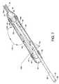
- FIG. 1is a plan view of the visible components of a miniature flexible thrombectomy catheter, the present invention
- FIG. 2is an isometric exploded and segmented view of the miniature flexible thrombectomy catheter
- FIG. 3is an assembled view in partial cross section of the components of the manifold and closely associated components and features thereof including a guidewire such as is incorporated in the use of the invention;
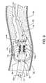
- FIG. 4is an exploded and sectioned isometric view of the distal tube of the invention including foreshortened portions of the proximal tube and of the components of a jet body which align and reside therein;
- FIG. 5is a cross section view along line 5 - 5 of FIG. 1 showing the spacing of the inflow orifices about the periphery of the proximal section of a distal tube;
- FIG. 6shows the alignment of the jet body within the proximal tube and the distal tube
- FIG. 7is an isometric cutaway view of the distal portion of the proximal section at one end of the distal tube showing high velocity fluid jet stream directed rearwardly from the jet orifices of the fluid jet emanator to form one or more cross stream jets;
- FIGS. 8 and 9illustrate the mode of operation of one form of the present invention, where FIG. 8 illustrates the miniature flexible thrombectomy catheter connected to ancillary devices, and where FIG. 9 is a side view of the distal region of the miniature flexible thrombectomy catheter in the performance of the method of use thereof within a small blood vessel;
- FIG. 10is a plan view of the visible components of another form of the miniature flexible thrombectomy catheter.
- FIG. 11is an isometric exploded and segmented view of the miniature flexible thrombectomy catheter of FIG. 10 ;
- FIG. 12is an assembled view in cross section of the components of the manifold of FIG. 11 and closely associated components and features thereof, as well as showing the inclusion of and the accommodation of the catheter tube;
- FIG. 13is a partial cross section view of the catheter tube along line 13 - 13 of FIG. 11 ;
- FIG. 14is a divided side view of the catheter tube showing extremes of the proximal spiral metal tube and the distal spiral metal tube;
- FIG. 15is a foreshortened exploded and separated isometric view of the components of the catheter tube extending from and including the proximal spiral metal tube to the tapered tip;
- FIG. 16is an isometric view of the distal end of the intermediate tube in close association with the proximal end of the distal spiral metal tube and of the proximal end of the intermediate tube with the distal end of the proximal spiral metal tube shown distanced from the intermediate tube;
- FIG. 17is a cross section view of the catheter tube along line 17 - 17 of FIG. 10 ;
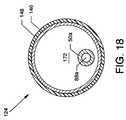
- FIG. 18is a cross section view of the catheter tube along line 18 - 18 of FIG. 17 ;
- FIG. 19is a cross section view of the catheter tube along line 19 - 19 of FIG. 17 ;
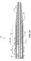
- FIG. 20is a section view along line 20 - 20 of FIG. 10 of the distal portion of the catheter tube including the tapered tip shown displaced from the catheter tube;
- FIG. 21is the same as FIG. 20 with the tapered tip shown engaging the distal spiral metal tube and the guidewire tube; and,
- FIGS. 22 and 23illustrate the mode of operation of one form of the present invention, where FIG. 22 illustrates the miniature flexible thrombectomy catheter connected to ancillary devices, and where FIG. 23 is a side view of the distal region of the miniature flexible thrombectomy catheter in the performance of the method of use thereof within a small blood vessel.
- FIG. 1is a plan view of the visible components of a miniature flexible thrombectomy catheter 10 , the present invention, including a one-piece manifold 12 having multiple structures extending therefrom or attached thereto and including a configured catheter tube 14 and other components as described herein.
- the catheter tube 14includes a hydrophilic coating to enhance deliverability along the vasculature or other structure.
- the visible portion of the one-piece manifold 12includes a central tubular body 16 , a threaded exhaust branch 18 , and a high pressure connection branch 20 extending angularly from the central tubular body 16 , a cavity body 22 extending proximally from the central tubular body 16 and partially shown and extending distally from the central tubular body 16 , and a threaded connection port 24 .
- the proximal end of the catheter tube 14secures to the manifold 12 by the use of a Luer fitting 26 accommodated by the threaded connection port 24 .
- the proximal end of the catheter tube 14extends through a strain relief tube 28 and through the Luer fitting 26 to communicate with the manifold 12 .
- the flexible catheter tube 14is comprised of tubular components consisting of a flexible proximal tube 30 joined and connected to a shorter section of flexible distal tube 32 having multiple sections of different radii.
- the tubular components of the flexible catheter tube 14are comprised of materials which promote pushability, torqueability, and which provide for operator feel.
- the proximal tube 30is comprised of braided polyimide, a synthetic polymeric resin or other suitable flexible material
- the distal tube 32is comprised of Pebax, a thermoplastic elastomer, or other suitable flexible material.
- the proximal tube 30is 4 Fr as measured with reference to the French catheter scale.
- the distal tube 32includes different radial sections, whereby a proximal section 32 a of the distal tube 32 can be 4 Fr size to mate with the distal end of the proximal tube 30 , and the distal section 32 b of the distal tube 32 can be drawn and reduced or otherwise processed to 3 Fr size.
- the proximal end of the distal section 32 a of the distal tube 32is drawn down in size and inserted into and secured within the distal interior of the proximal tube 30 by adhesive or by any other suitable method, as shown in FIG. 6 .
- the distal portion of the distal section 32 bis tapered to form a flexible tip 34 .
- the proximal tube 30 and the distal tube 32function as an exhaust tube for evacuation of macerated effluence from a thrombus or lesion site.
- the distal section 32 b of the catheter tube 14includes a plurality of outflow orifices 36 a - 36 n and a plurality of inflow orifices 38 a - 38 n, a proximally located radiopaque marker band 40 and a distally located radiopaque marker band 41 .
- a hemostasis nut 42aligned to and threadingly engaged with the proximal region of the cavity body 22 , and a threaded high pressure connection port 44 secured to the high pressure connection branch 20 by a Luer connector 46 .
- An introducer 48is also shown.
- FIG. 2is an isometric exploded and segmented view of the miniature flexible thrombectomy catheter 10 , the present invention
- FIG. 3is an assembled view in partial cross section of the components of the manifold 12 and closely associated components and features thereof, but including a guidewire 104 , such as is incorporated in the use of the invention.
- the catheter tube 14is comprised of the proximal tube 30 and the distal tube 32 which together serve and function as an exhaust tube.
- a collection of assembled componentsdelivers high pressure saline or other suitable fluid to the distal portion of the catheter tube 14 for creation of a cross stream jet.
- Such componentsare connected and include a proximally located flexible proximal high pressure tube 50 , a flexible nitinol tube 52 , and a relatively short flexible distal high pressure tube 54 having a fluid jet emanator 56 at the distal end.
- the proximal high pressure tube 50preferably of stainless steel or other suitable material, passes through and is generally distal to the strain relief tube 28 and extends along a greater portion of and within the lumens of the catheter tube 14 .
- the proximal end of the flexible nitinol tube 52connects to the distal end of the proximal high pressure tube 50 , whereby the flexible nitinol tube 52 extends distally from the distal end of the proximal high pressure tube 50 .
- the proximal end of the distally located and relatively short flexible distal high pressure tube 54preferably of stainless steel or other suitable material, is connected to the distal end of the nitinol tube 52 by a unique process, as later described in detail.
- the distal end of the distal high pressure tube 54including the fluid jet emanator 56 , is also shown in greater detail in FIGS. 4 , 5 , 6 and 7 .
- a proximally located support ring 43preferably of nitinol, is attached such as by a weldment to the nitinol tube 52 for support of the jet body 58 inside the proximal section 32 b of the distal tube 32 in cooperation with the marker band 41 .
- Some of the components forming the jet body 58 and other componentsare foreshortened and shown as partial lengths for the purpose of brevity and clarity.
- the manifold 12includes connected and communicating passageways and cavities ( FIG. 3 ) including a high pressure connection branch passageway 60 , an exhaust branch passageway 62 , a tapered central passageway 64 extending from and through the threaded connection port 24 and through the central tubular body 16 to and communicating with a multiple radius cavity 66 , which preferably is cylindrical, located central to the cavity body 22 .
- Threads 68are located about the proximal portion of the cavity body 22 at the proximal region of the manifold 12 for accommodation of internal threads 69 to the hemostasis nut 42 .
- Beneficial to the instant inventionis the use of a flexible self-sealing hemostasis valve 70 and a washer 72 which is located distal to the self-sealing hemostasis valve 70 , the shapes of and the functions of which are described in the referenced copending patent application Ser. No. 10/455,096.
- the self-sealing hemostasis valve 70 and the washer 72are aligned in and housed in the cavity 66 at the cavity body 22 at the proximal region of the manifold 12 .
- the hemostasis nut 42includes a centrally located cylindrical boss 74 .
- the washer 72 and the self-sealing hemostasis valve 70are captured in the greater radius portion of the cavity 66 by threaded engagement of the hemostasis nut 42 to the cavity body 20 of the manifold 12 .
- the cylindrical boss 74is brought to bear against the collective self-sealing hemostasis valve 70 and the washer 72 to resultingly bring pressure to bear as required against the self-sealing hemostasis valve 70 which pressure culminates in a forcible sealing of the self-sealing hemostasis valve 70 about a guidewire.
- a ferrule 76which is aligned within a passageway 78 of the threaded high pressure connection port 44 the combination of which is partially aligned within an interior passageway 80 of the Luer connector 46 .
- the proximal end of the proximal high pressure tube 50shown in segmented form in FIG. 2 , is utilized for delivery of high pressure ablation liquids and is suitably secured in a center passage of the ferrule 76 to communicate with the interior passageway 78 of the threaded high pressure connection port 44 , as shown in FIG. 3 .
- the proximal high pressure tube 50also extends through the high pressure connection branch passageway 60 , through part of the tapered central passageway 64 , through the strain relief tube 28 and Luer fitting 26 , and through a lumen 82 of the proximal tube 30 where connection is made to the nitinol tube 52 .
- the nitinol tube 52extends along the balance of the lumen 82 and thence through the lumen 84 of the proximal section 32 a, thence through the continuing lumen 84 of the distal section 32 b to connect to the shorter distal high pressure tube 54 within the proximal section 32 b .
- the lumen 84 having a variable diameterextends through the continuously fashioned proximal and distal sections 32 a and 32 b, respectively, comprising the distal tube 32 .
- the shorter distal high pressure tube 54continues to a support ring 86 where the fluid jet emanator 56 at the end of the shorter distal high pressure tube 54 is connected, such as by a weldment thereto, thereby supporting the shorter distal high pressure tube 54 and affixing the distal portion of the jet body 58 within the catheter tube 14 .
- FIG. 4is an exploded and sectioned isometric view of the distal tube 32 including a short portion of the proximal tube 30 and of the components of the jet body 58 which are aligned therein. Especially shown are the connected lumens of the jet body 58 , including a lumen 88 of the proximal high pressure tube 50 , a lumen 90 of the nitinol tube 52 , and a lumen 92 of the distal high pressure tube 54 , whereby the lumen 92 extends within the fluid jet emanator 56 and is terminated within the end of the fluid jet emanator 56 ( FIG. 5 ).
- the connected lumenstransport high pressure saline or other fluids to the plurality of proximally directed jet orifices 94 a - 94 n ( FIG. 5 ) located in the proximal region of the fluid jet emanator 56 for the creation of a cross stream jet incorporating the outflow orifices 36 a - 36 n and inflow orifices 38 a - 38 n .
- the outflow orifices 36 a - 36 n, as well as the inflow orifices 38 a - 38 nare spaced at 120° intervals or other suitable intervals ( FIG.
- FIG. 5is a cross section view along line 5 - 5 of FIG. 1 showing the spacing of the inflow orifices 38 a - 38 n about the periphery of the distal section 32 b of the distal tube 32 .
- the outflow orifices 36 a - 36 nare similarly spaced at 120°, as described in FIG. 4 .
- the portion of the lumen 92 and the connected jet orifices 94 a - 94 nlocated along and about the fluid jet emanator 56 .
- Current thrombectomy cathetersinclude fluid jet emanators formed by bending hypotubing 90 degrees and then forming a 350+ degree loop.
- the present designincorporates the fluid jet emanator 56 in the form of an arcuate foreshortened loop which occupies less space.
- the arcuate fluid jet emanator 56describes an arc of 160°, for the purpose of example and illustration, but may include an arc of other than 160°.
- the inwardly facing portion of the 160° arc of the fluid jet emanator 56describes an arcuate passageway 57 also shown in FIG. 4 .
- the 90 degree bendis formed near the distal portion of the distal high pressure tube 54 and is also bendingly directed in arcuate fashion slightly less than halfway around the circumference so that slightly less than one side of the distal section 32 b of the distal tube 32 will include the distal fluid jet emanator 56 rather than the full circumference.
- Such a relationshipallows passage of a guidewire in the space between the arcuate passageway 57 of the fluid jet emanator 56 and the opposed side of the distal section 32 b, even though passage may not center along the central longitudinal axis of the distal section 32 b of the distal tube 32 .
- the support ring 86welded to the fluid jet emanator 56 , the inner diameter is sufficient to pass the guidewire or even a guidewire lumen.
- FIG. 6shows the alignment of the jet body 58 within the proximal tube 30 and the distal tube 32 .
- the attachment of the proximal high pressure tube 50 to the nitinol tube 52is accomplished by using a proximal high pressure tube 50 which is slightly larger than the nitinol tube 52 to form an overlapping joint.
- the distal end of the proximal high pressure tube 50is annealed.
- proximal end of the nitinol tube 52is inserted into the lumen 88 at the distal end of the proximal high pressure tube 50 and a sealed joint 96 is formed by rotary swaging the proximal high pressure tube 50 over, about and onto the proximal end of the nitinol tube 52 with a rotary swage device.
- Nitinolis not easily formed to be utilized in small radius applications and thus the distal high pressure tube 54 of stainless steel, which is more readily and more reliably formed with respect to nitinol, is incorporated into use, whereby the small radius arcuate fluid jet emanator 56 is fashioned at the distal end of the distal high pressure tube 54 in order to fit within the small radius lumen 84 of the distal section 32 b .
- the proximal end of the distal high pressure tube 54is mated within the distal end of the nitinol tube 52 to form a joint 98 by a new and unique laser swaging process, as described later in detail. It is noted that the lumen 84 of the distal section 32 b continues through the distal section 32 b and is reduced to a narrow section 84 a at the flexible tip 34 .
- the stainless steel distal high pressure tube 54is plated with gold.
- the proximal end of the gold-plated stainless steel distal high pressure tube 54is inserted into the lumen 90 at the distal end of the nitinol tube 52 .
- the distal end of the nitinol tube 52is welded down onto the proximal end of the gold-plated stainless steel distal high pressure tube 54 to form and seal joint 98 .
- Poweris adjusted so the materials meet, but do not mix, to accomplish a swage.
- the gold platingserves as a barrier for mixing and to inhibit penetration of the weld.
- the mechanism of this weldingis that the nitinol tube 52 is actually being keyholed by the laser.
- Goldis highly reflective to the laser light used (1064 nm). Therefore, the laser light opens a hole in the nitinol and then reflects off the gold.
- the resultis a nitinol tube 52 which is essentially swaged onto a gold-plated stainless steel distal high pressure tube 54 with a laser.
- the gold-plated stainless steel distal high pressure tube 54is then annealed in the region that will be bent and formed to form the fluid jet emanator 56 .
- the annealingenables the distal portion of the stainless steel distal high pressure tube 54 to be readily formed into a distally located semicircle (half loop), i.e, the fluid jet emanator 56 .
- the annealingalso removes the thin layer of gold from the surface of the exposed distal stainless steel tube 54 .
- the stainless steel fluid jet emanator 56can be electrical discharge machined or otherwise processed to form the proximally directed jet orifices 94 a - 94 n in the loop portion of the fluid jet emanator 56 .
- FIG. 7is an isometric cutaway view of the distal portion of the proximal section 32 b at one end of the distal tube 32 showing high velocity fluid jet stream 118 directed rearwardly from the jet orifices 94 a - 94 n of the fluid jet emanator 56 to form one or more cross stream jets 120 .
- the operation of the cross stream jets 120is further described in FIG. 9 .
- FIGS. 8 and 9illustrate the mode of operation of one form of the present invention, where FIG. 8 illustrates the miniature flexible thrombectomy catheter 10 connected to ancillary devices, and where FIG. 9 illustrates a side view of the distal region of the miniature flexible thrombectomy catheter 10 in the performance of the method of use thereof within a small blood vessel 100 (shown in cross section) at a site of a thrombotic deposit or lesion 102 .
- the mode of operationis best understood by referring to FIGS. 8 and 9 , as well as previously described figures.
- the miniature flexible thrombectomy catheter 10is shown engaged over and about a guidewire 104 where the guidewire 104 engages the lumen 84 of the distal tube 32 at the tapered tip 34 of the distal tube 32 followed by passage through the lumen 82 of the proximal tube 30 , thence sealingly through the manifold 12 and closely associated components thereof to exit therefrom through the hemostasis nut 42 .
- a high pressure fluid source 106 and a high pressure fluid pump 110connect, as shown, to the manifold 12 via the threaded high pressure connection port 44 by Luer connector 108 or optionally by a direct connection to supply high pressure saline or other suitable fluid for the miniature flexible thrombectomy catheter 10 .
- An optional exhaust regulator 112 and a collection chamber 114connect to the threaded end of the threaded exhaust branch 18 of the manifold 12 by a Luer fitting 116 , as shown, for influencing the outflow from the miniature flexible thrombectomy catheter 10 .
- FIG. 9is a side view of the miniature flexible thrombectomy catheter 10 in the performance of the method of use thereof, with particular attention given to the distal section 32 b of the distal tube 32 including the flexible tapered tip 34 positioned in a blood vessel 100 at a site of a thrombotic deposit or lesion 102 .
- Multiple high velocity fluid jet streams 118 of saline, for example, or other suitable fluid,are shown being emitted in a proximal direction from the fluid jet emanator 56 to impinge upon thrombotic deposits or lesions 102 to carry and urge particulate thereof proximally.
- fluid jet emanatorsof appropriate size and/or configuration can be incorporated within the distal section 32 b of the distal tube 32 as an alternative to the fluid jet emanator 56 to emanate or emit one or more high velocity fluid jet streams 118 distally along or near the longitudinal axis of the distal tube 32 to accomplish the same purpose as that described for the fluid jet emanator 56 .
- the high velocity fluid jet streams 118 of salinepass outwardly through the outflow orifices 36 a - 36 n creating cross stream jets 120 (lower velocity jets) directed outwardly toward the wall of the blood vessel 100 and are influenced by the low pressure at the inflow orifices 38 a - 38 n to cause the cross stream jets 120 to flow circumferentially and distally to impinge on, provide drag forces on, and break up thrombotic deposits or lesions 102 , and to, by entrainment, urge and carry along one or more particles 102 a of thrombotic deposits or lesions 102 through the inflow orifices 38 a - 38 n, a relatively low pressure region, into the high velocity fluid jet streams 118 where the thrombus is further macerated into microscopic particles, and then into the distal tube lumen 84 ( FIG.
- the entrainment through the inflow orifices 38 a - 38 nis based on entrainment by the high velocity fluid jet streams 118 .
- the outflowis driven by internal pressure which is created by the high velocity fluid jet streams 118 and the fluid entrained through the inflow orifices 38 a - 38 n .
- Enhanced clot removalis attainable because of the recirculation pattern established between outflow and inflow orifices 36 a - 36 n and 38 a - 38 n, which creates a flow field that maximizes drag force on the wall-adhered thrombus.
- FIG. 10is a plan view of the visible components of another form of the miniature flexible thrombectomy catheter 10 , herein designated as the miniature flexible thrombectomy catheter 10 a, the present invention, employing many components and teachings of the first form of the present invention.
- the distal portion of the miniature flexible thrombectomy catheter 10 aincludes a one-piece manifold 122 having multiple structures extending therefrom or attached thereto including a configured catheter tube 124 distal to the manifold 122 , as well as other components attached to the structure of the manifold 122 as described herein.
- the catheter tube 124includes a hydrophilic coating and a thin and flexible plastic polymer jacket covering to enhance deliverability along the vasculature.
- the visible portion of the one-piece manifold 122includes a central tubular body 126 , a threaded exhaust branch 128 extending angularly from the central tubular body 126 , a threaded connection port 130 extending proximally from the central tubular body 126 , and a threaded connection port 132 partially shown extending distally from the central tubular body 126 .
- the proximal end of the catheter tube 124is secured to the manifold 122 by the use of a Luer fitting 134 accommodated by the threaded connection port 132 .
- the proximal end of the catheter tube 124extends through a strain relief tube 136 and through the Luer fitting 134 to communicate with the manifold 122 .
- a threaded high pressure connection port 138threadingly engages a Luer fitting 140 , whereby the Luer fitting 140 connectingly engages the threaded connection port 130 .
- the catheter tube 124comprises a substantially unitary, continuous, elongated, tubular structure containing or hosting various components and serving as an exhaust path extending distally from inside the manifold 122 and through the strain relief tube 136 and terminating at or near a flexible tapered tip 137 fashioned of suitable flexible silicone or other flexible rubber like material.
- the catheter tube 124which is substantially continuous except for a short portion, consists of connected tubular components including a proximal spiral metal tube 142 and a distal spiral metal tube 144 preferably of a smaller cross section dimension of the proximal spiral metal tube 142 , connected by a short configured intermediate tube 146 , preferably of Pebax or other suitable flexible material, therebetween.
- the proximal spiral metal tube 142 and the distal spiral metal tube 144can be laser cut or otherwise suitably fashioned.
- the pitch of the cutcan be progressively or otherwise varied along the length of the proximal spiral metal tube 142 and the distal spiral metal tube 144 comprising the majority of the catheter tube 124 .
- the use of the proximal spiral metal tube 142 , the distal spiral metal tube 144 , and the interceding intermediate tube 146instead of the easily kinkable, stiff, projecting metal tube of previous designs, preserves the excellent pushability and torqueability of previous designs, but is less kinkable and more flexible than previous designs.
- the spiral cut along the length of the catheter tube 124i.e., the proximal spiral metal tube 142 and the distal spiral metal tube 144 , can be progressively transitioned or otherwise varied in pitch from distal to proximal to produce a continuous transition from flexible to stiff which maximizes the pushability and “feel” of the catheter tube 124 .
- the pitch of the spiral cutsare shown as uniformly progressive, the spiral cut along the proximal spiral metal tube 142 and the distal spiral metal tube 144 can be of various pitch configurations to achieve the desired property.
- the length of the proximal spiral metal tube 142 and the distal spiral metal tube 144can be extended or shortened anywhere along the length of the catheter tube 124 , or the pitch can be configured to provide a desired mechanical property.
- a polymer jacket 148which can be transparent and which can be in the form of a shrink tube or other suitable configuration or material, encompasses the catheter tube 124 , thus creating a leak-free tubular structure, as well as adding mechanical and lubricious properties to the catheter tube 124 .
- a polymer tubesuch as, but not limited to, Pebax can be drawn down to encompass the catheter tube 124 .
- a uniformly progressive pitch of the proximal spiral metal tube 142 and the distal spiral metal tube 144can be seen through the preferably clear polymer jacket 148 if a transparent polymer is incorporated, starting with a wide pitch shown at 150 of the proximal spiral metal tube 142 at or near the strain relief tube 136 transitioning to a close pitch shown at 152 at or near the distal end of the distal spiral metal tube 144 .
- a guidewire tube exit region 154is located along the intermediate tube 146 and the proximal portion of a guidewire tube 155 having a lumen 157 ( FIG. 15 ) is located at the guidewire tube exit region 154 , as later described in detail.
- the proximal spiral metal tube 142is slightly larger than 3 Fr, as measured with reference to French catheter scale.
- the distal spiral metal tube 144can also be slightly larger or smaller than 3 Fr.
- the intermediate tube 146can be of an appropriate size and configuration to mate with the distal end of the proximal spiral metal tube 142 and the proximal end of the distal spiral metal tube 144 .
- the proximal spiral metal tube 142 and the distal proximal spiral metal tube 144 in combination with the intermediate tube 148function as an exhaust tube for evacuation of macerated effluence from a thrombus or lesion site.
- the cross section dimension of the distal spiral metal tube 144preferably is somewhat less than the cross section dimension of the proximal spiral metal tube 142 , thereby providing a greater degree of flexibility to the distal portion of the catheter tube 124 , such as taught with respect to the catheter tube 14 of the miniature flexible thrombectomy catheter 10 .
- FIG. 11is an isometric exploded and segmented view of the miniature flexible thrombectomy catheter 10 a, the present invention
- FIG. 12is an assembled view in cross section of the components of the manifold 122 and closely associated components and features thereof, as well as showing the inclusion of and the accommodation of the catheter tube 124 .
- the catheter tube 124is comprised of the proximal spiral metal tube 142 and the distal spiral metal tube 144 and the intermediate tube 146 which, together and collectively, serve and function as an exhaust tube.
- a jet body 58 a similar in most respects in construction and in the method of construction to the jet body 58 of the miniature flexible thrombectomy catheter 10delivers high pressure saline or other suitable fluid to the distal portion of the catheter tube 124 for creation of cross stream jets.
- Such similar components comprising the jet body 58 aare suffixed by the letter “a” and are connected and include the proximally located flexible proximal high pressure tube 50 a, which in this form includes a straight proximal end, the flexible nitinol tube 52 a, and the distally located relatively short flexible distal high pressure tube 54 a having the fluid jet emanator 56 a at the distal end. Joints 96 a and 98 a are shown in FIG. 15 .
- the proximal high pressure tube 50 apasses through and is generally distal to the strain relief tube 136 and extends along a greater portion of and within the lumens of the catheter tube 124 .
- Some of the components forming the jet body 58 a and other componentsare foreshortened and shown as partial lengths for the purpose of brevity and clarity.
- the manifold 122includes connected and communicating passageways including a central passageway 162 extending from and through the threaded connection port 132 and thence through the central tubular body 126 to and communicating with and connecting to and being a part of the interior of the threaded connection port 130 .
- An exhaust branch passageway 164 central to the threaded exhaust branch 128communicates with the central passageway 162 .
- a ferrule 166which aligns within a passageway 168 of the threaded high pressure connection port 138 , the combination of which is partially accommodated within the proximal portion of the central passageway 162 of the manifold 122 .
- the proximal end of the proximal high pressure tube 50 ais utilized for delivery of high pressure ablation liquids and suitably secures in a center passage of the ferrule 166 .
- the proximal high pressure tube 50 aalso extends directly through the central passageway 162 , through the lumen 170 ( FIG. 13 ) of the proximal spiral metal tube 142 , through a lumen 172 ( FIG. 16 ) of the intermediate tube 146 , and partially through and along proximal portion of the lumen 174 of the distal spiral metal tube 144 at or near where connection is made to the nitinol tube 52 a.
- FIG. 13is a partial cross section view of the catheter tube 124 along line 13 - 13 of FIG. 11
- FIG. 14is a divided side view of the catheter tube 124 showing extremes of the proximal spiral metal tube 142 and the distal spiral metal tube 144 .
- the material of the polymer jacket 148 encasing the proximal spiral metal tube 142 and the distal spiral metal tube 144is transparent, the proximal spiral metal tube 142 and the distal spiral metal tube 144 are easily viewed therethrough.
- a proximal spiral cut 176extends along and about the proximal spiral metal tube 142 and a distal spiral cut 178 extends along and about the distal spiral metal tube 144 , whereby the substantially full length polymer jacket 148 is closely aligned over and about the proximal spiral cut 176 of the proximal spiral metal tube 142 and closely aligned over and about the distal spiral cut 178 of the distal spiral metal tube 144 , as well as over and about the exterior of the intermediate tube 146 ( FIG. 11 ) which also is visible.
- the proximal spiral cut 176 and the distal spiral cut 178can be produced by a laser cutting tool, or other suitable fashioning methods can be incorporated into use in the substantially continuous catheter tube 124 which can include various spiral pitch configurations.
- proximal spiral metal tube 142formed by the proximal spiral cut 176 having a wide pitch 150 which can be a constant pitch or changing progressive pitch transitioning to a medium pitch 151 as formed by the proximal spiral cut 176 which can be a constant pitch or changing progressive pitch
- distal spiral metal tube 144formed by the distal spiral cut 178 having a close pitch 152 which can be a constant pitch or changing progressive pitch
- Additional wide pitch regions 180 and 182 interrupting the close pitch 152 of the distal spiral metal tube 144 for accommodation of the outflow orifices 156 a - 156 n and the inflow orifices 158 a - 158 nare shown in FIG. 14 .
- Many configurationscan be incorporated to achieve required pushability and torqueability to meet different criteria, whereby the wide pitch, the medium pitch, and the close pitch features can populate various locations along the proximal spiral metal tube 142 and/or the distal spiral metal tube 144 .
- FIG. 15is an exploded and separated isometric view of the components of the catheter tube 124 extending from and including the proximal spiral metal tube 142 to the tapered tip 137 , some components being foreshortened with respect to length for the purpose of illustration and clarity.
- the shown portion of the catheter tube 124includes the spiral metal tube 142 , the polymer jacket 148 , the intermediate tube 146 including the formed portion 184 , the flexible guidewire tube 155 of polymer construction, the proximal high pressure tube 50 a, the nitinol tube 52 a, the distal high pressure tube 54 a, the fluid jet emanator 56 a, the distal spiral metal tube 144 , and other components and features within, along and about the catheter tube 124 .
- the proximal high pressure tube 50 a with a lumen 88 aextends from the manifold 122 , as previously described, through the lumen 170 in the proximal spiral metal tube 142 , through the lumen 172 of the intermediate tube 146 at or near which point the proximal high pressure tube 50 a connects to the proximal end of the nitinol tube 52 a .
- the distal end of the nitinol tube 52 ais connected to the proximal end of the distal high pressure tube 54 a having the included fluid jet emanator 56 a, whereby the nitinol tube 52 a and the distal high pressure tube 54 a having the included fluid jet emanator 56 a extend along and within the lumen 174 of the distal spiral metal tube 144 .
- the fluid jet emanator 56 a at the distal end of the distal high pressure tube 54 ais located and secured distally in the lumen 174 of the distal spiral metal tube 144 just distal of the inflow orifices 158 a - 158 n, as shown in FIG. 20 .
- the outer arcuate perimeter of the fluid jet emanator 56 ais suitably secured, such as by, but not limited to, a weldment to the inner diameter of the distal spiral metal tube 144 , thereby fixing the fluid jet emanator 56 a to the distal spiral metal tube 144 and securing the fluid jet emanator 56 a with respect to the outflow orifices 156 a - 156 n and the inflow orifices 158 a - 158 n, ( FIG. 20 ), thereby eliminating the use of a radiopaque marker band or of a support ring as a securing or support device.
- the guidewire tube 155 having the lumen 157is securely accommodated by a crescent-shaped truncated and rounded slot 188 at the formed tubular portion 184 and is secured thereto by an adhesive or other suitable attachment methods, if required, and extends distally from the formed tubular portion 184 at the guidewire tube exit region 154 through an orifice 190 ( FIG. 16 ), where the orifice 190 transitions between the distal end of the truncated and rounded slot 188 and the lumen 172 of the distal spiral metal tube 144 .
- the guidewire tube 155continues through the arcuate passageway 57 a of the fluid jet emanator 56 a, and further through the distal portion of the lumen 174 of the spiral metal tube 144 where the distal portion of the guidewire tube 155 terminates securely, such as by heat bonding or other suitable means, within the passageway 196 of the flexible tapered tip 137 .
- Heatcan be applied to form the tapered tip 137 of increasingly flexible shape in a distal direction at the end of the catheter tube 124 , as well as to engagingly secure the distal end portion of the guidewire tube 155 to and within the tapered tip 137 .
- the tapered tip 137may also be formed through a cold drawn down process or may be physically attached through adhesives or polymer reintegration.
- FIG. 16is an isometric view of the distal end of the intermediate tube 146 in close association with the proximal end of the distal spiral metal tube 144 and of the proximal end of the intermediate tube 146 with the distal end of the proximal spiral metal tube 142 shown distanced from the intermediate tube 146 .
- the intermediate tube 146includes opposed flared ends 192 and 194 for accommodated connection with the proximal spiral metal tube 142 and with the distal spiral metal tube 144 , respectively.
- the guidewire tube exit region 154which is delineated mostly by the formed tubular portion 184 of the intermediate tube 146 .
- the formed tubular portion 184includes geometry in the form of a truncated and rounded slot 188 of decreasing depth in a proximal direction which accommodates the guidewire tube 155 ( FIG. 15 ).
- the truncated and rounded slot 188is substantially formed in the shape of a nearly full semicircular arc at the extreme distal end of the formed tubular portion 184 .
- the arcwhile the radius remains constant, is decreased progressing proximally from the extreme distal end of the formed tubular portion 184 to provide for an angled transitional accommodation of the guidewire tube 155 , as shown in FIGS. 15 and 17 .
- Other transitional accommodation for routing of the guidewire tube 155is offered by the orifice 190 , previously referenced in connection with FIG. 15 .
- the lumen 172 interior to the intermediate tube 146depending on component lengths, generally can accommodate a portion of the proximal high pressure tube 50 a and also functions as part of the overall effluent exhaust path.
- FIG. 17is a cross section view of the catheter tube 124 along line 17 - 17 of FIG. 10 . Shown in particular is the guidewire tube exit region 154 , the formed tubular portion 184 , and the proximal end of the guidewire tube 155 at the guidewire tube exit region 154 .
- the proximal end of the guidewire tube 155is accommodated by the truncated and rounded slot 188 and a portion of the co-located overlying polymer jacket 148 to which it is secured, if required, by an adhesive, by welding, or other such suitable method, and by the orifice 190 at the distal end of the truncated and rounded slot 188 .
- the proximal end of the guidewire tube 155is of such length that the outer profile of the catheter tube 124 is not exceeded so as to maintain the desired minimal catheter profile.
- the portion of the truncated and rounded slot 188which is not occupied by the proximal end of the guidewire tube 155 and which is proximal to the proximal end of the guidewire tube 155 , can also be utilized to accommodate a guidewire without structure interference.
- the proximal high pressure tube 50 ahaving the lumen 88 a ( FIGS. 18 and 19 ) passing through the lumen 172 .
- Lumen 172 of the intermediate tube 146functions as a portion of the exhaust route extending the length of the catheter tube 124 .
- FIG. 18is a cross section view of the catheter tube 124 along line 18 - 18 of FIG. 17 . Illustrated in particular is the lumen 172 of the intermediate tube 146 which functions as part of the exhaust route through the catheter tube 124 with minimal obstructions or restrictions therein.
- FIG. 19is a cross section view of the catheter tube 124 along line 19 - 19 of FIG. 17 . Illustrated in particular is the alignment and accommodation of the guidewire tube 155 in the truncated and rounded slot 188 at the formed tubular portion 184 of the intermediate tube 146 .
- FIG. 20is a section view of the distal portion of the catheter tube 124 including the tapered tip 137 along line 20 - 20 of FIG. 10 where the tapered tip 137 is shown removed from the distal spiral metal tube 144 , and FIG. 21 is the same as FIG. 20 with the tapered tip 137 shown engaging the distal spiral metal tube 144 and the guidewire tube 155 .
- the radiopaque marker band of the first form of the inventionis not included due to the trackability of the metal structure of the catheter tube 124 .
- the outer arcuate semi-perimeter of the fluid jet emanator 56 a opposing the arcuate passageway 57 ais suitably secured, such as, but not limited to, a weld directly to the distal interior of the distal spiral metal tube 144 of the catheter tube 124 at a location just distal to the inflow orifices 158 a - 158 n .
- a support ringsuch as support ring 86 , is not required for mounting of the fluid jet emanator 56 a as the structure of the distal spiral metal tube 144 is sufficiently sturdy enough for mounting.
- the metal structure of the distal spiral metal tube 144is of sufficient strength to prevent any deformation or collapsing of the distal spiral metal tube 144 in the region of the inflow orifices 158 a - 158 n without the use of a support ring.
- the flexible tapered tip 137includes a passageway 196 for fixed accommodation of the distal end of the guidewire tube 155 and also includes a reduced constant radius section 198 which is accommodated by and secured within the distal portion of the lumen 174 of the distal spiral metal tube 144 .
- the flexible tapered tip 137as opposed to a rounded but nontapered tip, can part and more easily penetrate thrombotic deposits or lesions during insertional travel in a distal direction instead of advancing or pushing such thrombotic deposits or lesions distally.
- the decreasing diameter in a distal direction of the tapered tip 137also allows for increasing flexibility to negotiate and pass through tortuous vascular paths.
- the portion of the catheter tube 124 which immediately follows the tapered tip 137 on a tortuous negotiation and passageis influenced by the supportive structure of the distal spiral metal tube 144 which offers reinforcement to form and contribute to maintaining the diameter of the catheter tube 124 along the entire catheter tube 124 against bending or collapsing due to tortuous paths or negative pressures, especially in the regions in close proximity to or including the inflow orifices 158 a - 158 n and the outflow orifices 156 a - 156 n .
- Such supportallows the use of thinner wall dimension for the catheter tube 124 to allow for a larger and more effective and efficiently sized exhaust lumen, i.e., the combination of lumens 170 , 172 and 174 , as well as contributing to a lesser sized outer diameter.
- Such supportalso contributes to supportively maintaining the diameter and overall shape of the catheter tube 124 when it is pushed or advanced along a vein or other vessel, as well as providing torsional support.
- FIGS. 22 and 23illustrate the mode of operation of one form of the present invention where FIG. 22 illustrates the miniature flexible thrombectomy catheter 10 a connected to ancillary devices, and where FIG. 23 illustrates a side view of the distal region of the miniature flexible thrombectomy catheter 10 a in the performance of the method of use thereof within a small blood vessel 100 (shown in cross section) at a site of a thrombotic deposit or lesion 102 .
- the mode of operationis best understood by referring to FIGS. 22 and 23 , as well as previously described figures.
- the rapid exchange fluid jet thrombectomy device 10 ais shown engaged over and about a guidewire 200 where the guidewire 200 (previously engaged in the blood vessel 100 of FIG. 23 ) first engages the lumen 157 of the guidewire tube 155 at the tapered tip 137 of the distal spiral metal tube 144 followed by exiting of the guidewire 200 from the lumen 157 ( FIG. 17 ) at the proximal end of the guidewire tube 155 at the guidewire tube exit region 154 .
- a fluid source 106 and a high pressure fluid pump 110connect as shown to the manifold 122 via the threaded high pressure connection port 138 by the Luer fitting 140 or optionally by a direct connection.
- An optional exhaust regulator 112 and a collection chamber 114connect to the threaded branch end of the exhaust branch 128 of the manifold 122 by a Luer fitting 202 , as shown.
- FIG. 23is a side view of the distal portion of the rapid exchange fluid jet thrombectomy device 10 a in the performance of the method of use thereof, with particular attention given to the distal region of the distal spiral metal tube 144 including the flexible tapered tip 137 positioned in a blood vessel 100 at a site of a thrombotic deposit or lesion 102 .
- Multiple high velocity fluid jet streams 118 of saline, for example, or other suitable fluid,are shown being emitted in a proximal direction from the fluid jet emanator 56 a to impinge upon and carry away thrombotic deposits or lesions 102 .
- fluid jet emanatorsof appropriate size and/or configuration can be incorporated within the distal portion of the distal spiral metal tube 144 as an alternative to the fluid jet emanator 56 a illustrated in this figure to emanate or emit one or more high velocity fluid jet streams 118 distally along or near the longitudinal axis of the distal spiral metal tube 144 to accomplish the same purpose as that described for the fluid jet emanator 56 a .
- the high velocity fluid jet streams 118 of salinepass outwardly through the outflow orifices 156 a - 156 n in a radial direction creating cross stream jets 120 (lower velocity jets) directed outwardly toward the wall of the blood vessel 100 and are influenced by the low pressure at the inflow orifices 158 a - 158 n to cause the cross stream jets 120 to flow circumferentially and distally to impinge on, provide drag forces on, and break up thrombotic deposits or lesions 102 and to, by entrainment, urge and carry along the particles 102 a of thrombotic deposits or lesions 102 through the inflow orifices 158 a - 158 n, a relatively low pressure region, into the high velocity fluid jet streams 118 where the thrombus is further macerated into microscopic particles, and then into the lumen 174 of the distal spiral metal tube 144 ( FIG.
- the entrainment through the inflow orifices 158 a - 158 nis based on entrainment by the high velocity fluid jet streams 118 .
- the outflowis driven by internal pressure which is created by the high velocity fluid jet streams 118 and the fluid entrained through the inflow orifices 158 a - 158 n .
- Enhanced clot removalis attainable because of the recirculation pattern established between outflow and inflow orifices 156 a - 156 n and 158 a - 158 n, which creates a flow field that maximizes drag force on wall-adhered thrombus.
Landscapes
- Health & Medical Sciences (AREA)
- Life Sciences & Earth Sciences (AREA)
- General Health & Medical Sciences (AREA)
- Surgery (AREA)
- Veterinary Medicine (AREA)
- Engineering & Computer Science (AREA)
- Biomedical Technology (AREA)
- Heart & Thoracic Surgery (AREA)
- Public Health (AREA)
- Animal Behavior & Ethology (AREA)
- Anesthesiology (AREA)
- Hematology (AREA)
- Pulmonology (AREA)
- Vascular Medicine (AREA)
- Nuclear Medicine, Radiotherapy & Molecular Imaging (AREA)
- Biophysics (AREA)
- Medical Informatics (AREA)
- Molecular Biology (AREA)
- Orthopedic Medicine & Surgery (AREA)
- Media Introduction/Drainage Providing Device (AREA)
- Surgical Instruments (AREA)
Abstract
Description
- 10 miniature flexible thrombectomy catheter
- 10aminiature flexible thrombectomy catheter
- 12 manifold
- 14 catheter tube
- 16 central tubular body
- 18 threaded exhaust branch
- 20 high pressure connection branch
- 22 cavity body
- 24 threaded connection port
- 26 Luer fitting
- 28 strain relief tube
- 30 proximal tube
- 32 distal tube
- 32aproximal section (of32)
- 32bdistal section (of32)
- 34 flexible tip
- 36a-noutflow orifices
- 38a-ninflow orifices
- 40 marker band
- 41 market band
- 42 hemostasis nut
- 43 support ring
- 44 threaded high pressure connector port
- 46 Luer connector
- 48 introducer
- 50 proximal high pressure tube
- 50aproximal high pressure tube
- 52 nitinol tube
- 52anitinol tube
- 54 distal high pressure tube
- 54adistal high pressure tube
- 56 fluid jet emanator
- 56afluid jet emanator
- 57 arcuate passageway
- 57aarcuate passageway
- 58 jet body
- 58ajet body
- 60 high pressure connection branch passageway
- 62 exhaust branch passageway
- 64 tapered central passageway
- 66 cavity
- 68 threads
- 69 threads
- 70 self-sealing hemostasis valve
- 72 washer
- 74 cylindrical boss
- 76 ferrule
- 78 passageway
- 80 interior passageway
- 82 lumen (of
proximal section 32a) - 84 lumen (of
distal section 32b) - 84anarrow section (of lumen84)
- 86 support ring
- 88 lumen (of proximal high pressure tube50)
- 88alumen (of proximal
high pressure tube 50a) - 90 lumen (of nitinol tube52)
- 90alumen (of
nitinol tube 52a) - 92 lumen (of distal high pressure tube54)
- 92alumen (of distal
high pressure tube 54a) - 94a-njet orifices
- 96 joint
- 96ajoint
- 98 joint
- 98ajoint
- 100 blood vessel
- 102 thrombotic deposit or lesion
- 102aparticles
- 104 guidewire
- 106 high pressure fluid source
- 108 Luer fitting
- 110 high pressure fluid pump
- 112 exhaust regulator
- 114 collection chamber
- 116 Luer fitting
- 118 high velocity fluid jet stream
- 120 cross stream jets
- 122 manifold
- 124 catheter tube
- 126 central tubular body
- 128 threaded exhaust branch
- 130 threaded connection port
- 132 threaded connection port
- 134 Luer fitting
- 136 strain relief tube
- 137 tapered tip
- 138 threaded high pressure connection port
- 140 Luer fitting
- 142 proximal spiral metal tube
- 144 distal spiral metal tube
- 146 intermediate tube
- 148 polymer jacket
- 150 wide pitch
- 151 medium pitch
- 152 close pitch
- 154 guidewire tube exit region
- 155 guidewire tube
- 156a-noutflow orifices
- 157 lumen (of guidewire tube155)
- 158a-ninflow orifices
- 162 central passageway
- 164 exhaust branch passageway
- 166 ferrule
- 168 passageway
- 170 lumen (of proximal spiral metal tube142)
- 172 lumen (of intermediate tube146)
- 174 lumen (of distal spiral metal tube144)
- 176 proximal spiral cut
- 178 distal spiral cut
- 180 wide pitch region
- 182 wide pitch region
- 184 formed tubular portion
- 188 truncated and rounded slot
- 190 orifice.
- 192 flared end
- 194 flared end
- 196 passageway
- 198 reduced constant radius section
- 200 guidewire
- 202 Luer fitting
Claims (22)
Priority Applications (4)
| Application Number | Priority Date | Filing Date | Title |
|---|---|---|---|
| US11/702,990US8012117B2 (en) | 2007-02-06 | 2007-02-06 | Miniature flexible thrombectomy catheter |
| EP08725186.4AEP2162179B1 (en) | 2007-02-06 | 2008-02-05 | Miniature flexible thrombectomy catheter |
| PCT/US2008/001515WO2008097545A2 (en) | 2007-02-06 | 2008-02-05 | Miniature flexible thrombectomy catheter |
| US14/100,155US9585686B2 (en) | 2005-09-28 | 2013-12-09 | Infusion flow guidewire system |
Applications Claiming Priority (1)
| Application Number | Priority Date | Filing Date | Title |
|---|---|---|---|
| US11/702,990US8012117B2 (en) | 2007-02-06 | 2007-02-06 | Miniature flexible thrombectomy catheter |
Publications (2)
| Publication Number | Publication Date |
|---|---|
| US20080188831A1 US20080188831A1 (en) | 2008-08-07 |
| US8012117B2true US8012117B2 (en) | 2011-09-06 |
Family
ID=39676804
Family Applications (1)
| Application Number | Title | Priority Date | Filing Date |
|---|---|---|---|
| US11/702,990ActiveUS8012117B2 (en) | 2005-09-28 | 2007-02-06 | Miniature flexible thrombectomy catheter |
Country Status (3)
| Country | Link |
|---|---|
| US (1) | US8012117B2 (en) |
| EP (1) | EP2162179B1 (en) |
| WO (1) | WO2008097545A2 (en) |
Cited By (10)
| Publication number | Priority date | Publication date | Assignee | Title |
|---|---|---|---|---|
| US20100312223A1 (en)* | 2009-06-03 | 2010-12-09 | Medrad, Inc. | Rapid exchange fluid jet catheter and method |
| US20110152908A1 (en)* | 2009-12-16 | 2011-06-23 | Medrad, Inc. | Catheter Including Composite Guide and Methods for use and manufacturing of the Same |
| US8597238B2 (en) | 2004-12-10 | 2013-12-03 | Medrad, Inc. | Enhanced cross stream mechanical thrombectomy catheter |
| US9216034B2 (en) | 2011-10-04 | 2015-12-22 | Angioworks Medical, B.V. | Devices and methods for percutaneous endarterectomy |
| US9585686B2 (en) | 2005-09-28 | 2017-03-07 | Boston Scientific Limited | Infusion flow guidewire system |
| US9693795B2 (en) | 2015-05-27 | 2017-07-04 | Angioworks Medical B.V. | Devices and methods for minimally invasive tissue removal |
| US10265502B2 (en) | 2013-02-19 | 2019-04-23 | Beth Israel Deaconess Medical Center, Inc. | Adjustable stiffness catheter |
| US20210322732A1 (en)* | 2020-04-20 | 2021-10-21 | Surmodics Md, Llc | Radial Balloon Catheter |
| US11679195B2 (en) | 2021-04-27 | 2023-06-20 | Contego Medical, Inc. | Thrombus aspiration system and methods for controlling blood loss |
| WO2025029855A1 (en)* | 2023-07-31 | 2025-02-06 | Abiomed, Inc. | Access device with dual entry ports |
Families Citing this family (24)
| Publication number | Priority date | Publication date | Assignee | Title |
|---|---|---|---|---|
| WO2012021697A1 (en) | 2010-08-12 | 2012-02-16 | Medrad, Inc. | Infusion flow system and fluid coupling |
| US9050127B2 (en)* | 2012-06-27 | 2015-06-09 | Boston Scientific Limited | Consolidated atherectomy and thrombectomy catheter |
| WO2014078506A2 (en)* | 2012-11-14 | 2014-05-22 | Ams Research Corporation | Cell delivery device and system with anti-clumping feature and methods for pelvic tissue treatment |
| US20140277006A1 (en) | 2013-03-14 | 2014-09-18 | Medrad, Inc. | Thrombectomy catheters, systems and methods |
| US10828051B2 (en)* | 2014-07-28 | 2020-11-10 | Shaw P. Wan | Suction evacuation device |
| US10463351B2 (en) | 2014-10-15 | 2019-11-05 | Cook Medical Technologies Llc | Transitional geometry for an expandable medical device |
| US10617847B2 (en) | 2014-11-04 | 2020-04-14 | Orbusneich Medical Pte. Ltd. | Variable flexibility catheter support frame |
| EP4008389B1 (en) | 2014-11-04 | 2025-07-02 | OrbusNeich Medical Pte. Ltd. | Progressive flexibility catheter support frame |
| EP3242608B1 (en) | 2015-01-09 | 2020-11-25 | Accurate Medical Therapeutics Ltd. | Embolization microcatheter |
| ES2721312T3 (en)* | 2015-03-02 | 2019-07-30 | Accurate Medical Therapeutics Ltd | Catheters with lateral openings to modify and administer suspensions to a subject |
| US10251636B2 (en)* | 2015-09-24 | 2019-04-09 | Ethicon Llc | Devices and methods for cleaning a surgical device |
| GB2538124B (en)* | 2015-12-07 | 2017-06-21 | Diasolve Ltd | Microcatheter apparatus |
| WO2017152086A1 (en)* | 2016-03-03 | 2017-09-08 | Boston Scientific Scimed, Inc. | Accessory devices for use with catheters |
| WO2017191636A1 (en) | 2016-05-04 | 2017-11-09 | Accurate Medical Therapeutics Ltd. | Embolization microcatheter head having slitted pattern |
| US10869990B2 (en) | 2016-07-13 | 2020-12-22 | Boston Scientific Scimed, Inc. | Infusion catheter with high pressure capabilities |
| EP3703583B1 (en) | 2017-11-02 | 2025-10-15 | Accurate Medical Therapeutics Ltd. | Embolization catheter with integral filter |
| US11931060B2 (en) | 2018-01-10 | 2024-03-19 | Boston Scientific Scimed, Inc. | Aspiration medical device |
| CN112672780B (en)* | 2018-09-10 | 2023-08-29 | 祥丰医疗私人有限公司 | Flexible Conduit Support Frame |
| EP3938024A1 (en) | 2019-03-13 | 2022-01-19 | Abiomed, Inc. | Dual hub introducer sheath |
| BR112021023510A2 (en) | 2019-05-23 | 2022-01-18 | Accurate Medical Therapeutics Ltd | Embolization catheter for reflux-free delivery of microspheres. |
| US11744601B2 (en)* | 2019-08-30 | 2023-09-05 | Biosense Webster (Israel) Ltd. | Sinuplasty tool |
| US12409299B2 (en)* | 2019-09-20 | 2025-09-09 | Abiomed, Inc. | Bifurcated hub |
| JP7282388B2 (en)* | 2020-03-30 | 2023-05-29 | 株式会社東海メディカルプロダクツ | Catheter tip and catheter with catheter tip |
| CN117677353A (en) | 2021-05-04 | 2024-03-08 | 波士顿科学国际有限公司 | Aspiration medical device |
Citations (136)
| Publication number | Priority date | Publication date | Assignee | Title |
|---|---|---|---|---|
| US1902418A (en) | 1931-11-02 | 1933-03-21 | Jensen Salsbery Lab Inc | Surgical instrument |
| US1904241A (en)* | 1926-12-31 | 1933-04-18 | Kammerer Erwin | Compound metal stock |
| US3752617A (en) | 1969-10-13 | 1973-08-14 | Sherwood Medical Ind Inc | Apparatus for extruding products of plural components of varied proportions with scrap reclamation |
| US3930505A (en) | 1974-06-24 | 1976-01-06 | Hydro Pulse Corporation | Surgical apparatus for removal of tissue |
| GB1571459A (en) | 1977-12-20 | 1980-07-16 | Instavac Ltd | Vacuum pumps and vacuum pump assemblies |
| US4224943A (en) | 1979-01-24 | 1980-09-30 | Sorenson Research Co., Inc. | Cannula and method for bidirectional blood flow |
| US4248234A (en) | 1979-03-08 | 1981-02-03 | Critikon, Inc. | Catheter with variable flexural modulus and method of using same |
| US4290428A (en) | 1978-09-01 | 1981-09-22 | Durand Alain J M | Catheter with bulb |
| US4328811A (en) | 1980-07-28 | 1982-05-11 | Fogarty Thomas J | Calibrating dilation catheter |
| US4385635A (en) | 1980-04-25 | 1983-05-31 | Ruiz Oscar F | Angiographic catheter with soft tip end |
| US4495255A (en)* | 1980-10-30 | 1985-01-22 | At&T Technologies, Inc. | Laser surface alloying |
| DE3421390C2 (en) | 1984-06-08 | 1986-07-17 | Werner Dr.med. 4330 Mülheim Schubert | High pressure catheter with cutting and / or abrasion device |
| US4631052A (en) | 1984-01-03 | 1986-12-23 | Intravascular Surgical Instruments, Inc. | Method and apparatus for surgically removing remote deposits |
| US4636346A (en) | 1984-03-08 | 1987-01-13 | Cordis Corporation | Preparing guiding catheter |
| US4690672A (en) | 1984-09-06 | 1987-09-01 | Veltrup Elmar M | Apparatus for removing solid structures from body passages |
| US4739768A (en) | 1986-06-02 | 1988-04-26 | Target Therapeutics | Catheter for guide-wire tracking |
| US4747405A (en) | 1984-03-01 | 1988-05-31 | Vaser, Inc. | Angioplasty catheter |
| DE3705339A1 (en) | 1987-02-19 | 1988-09-01 | Siemens Ag | CATHETER FOR TREATING VESSEL NARROWS |
| US4775371A (en) | 1986-09-02 | 1988-10-04 | Advanced Cardiovascular Systems, Inc. | Stiffened dilatation catheter and method of manufacture |
| US4781186A (en) | 1984-05-30 | 1988-11-01 | Devices For Vascular Intervention, Inc. | Atherectomy device having a flexible housing |
| US4782834A (en) | 1987-01-06 | 1988-11-08 | Advanced Cardiovascular Systems, Inc. | Dual lumen dilatation catheter and method of manufacturing the same |
| US4790813A (en) | 1984-12-17 | 1988-12-13 | Intravascular Surgical Instruments, Inc. | Method and apparatus for surgically removing remote deposits |
| US4842579A (en) | 1984-05-14 | 1989-06-27 | Surgical Systems & Instruments, Inc. | Atherectomy device |
| US4861336A (en) | 1987-04-01 | 1989-08-29 | Helzel Manfred W | Puncture catheter |
| US4883459A (en) | 1983-07-29 | 1989-11-28 | Reynaldo Calderon | Retrograde perfusion |
| US4888146A (en) | 1988-05-19 | 1989-12-19 | Dandeneau James V | Method and apparatus of forming extruded article |
| US4898574A (en) | 1986-05-08 | 1990-02-06 | Olympus Optical Co., Ltd. | Lithotomic apparatus |
| US4898591A (en) | 1988-08-09 | 1990-02-06 | Mallinckrodt, Inc. | Nylon-PEBA copolymer catheter |
| US4902276A (en) | 1986-06-09 | 1990-02-20 | The Regents Of The University Of California | Apparatus and method for removing obstructions in bodily organs or cavities |
| US4913698A (en) | 1987-10-26 | 1990-04-03 | Marui Ika Company, Limited | Aqua-stream and aspirator for brain surgery |
| US4950238A (en) | 1988-07-07 | 1990-08-21 | Clarence E. Sikes | Hydro-rotary vascular catheter |
| EP0232678B1 (en) | 1985-12-31 | 1991-04-03 | Arnold Neracher | Surgical device |
| US5011469A (en) | 1988-08-29 | 1991-04-30 | Shiley, Inc. | Peripheral cardiopulmonary bypass and coronary reperfusion system |
| US5085649A (en) | 1990-11-21 | 1992-02-04 | Flynn Vincent J | Torque controlled tubing |
| US5086842A (en) | 1989-09-07 | 1992-02-11 | Institut Francais Du Petrole | Device and installation for the cleaning of drains, particularly in a petroleum production well |
| US5092873A (en) | 1990-02-28 | 1992-03-03 | Devices For Vascular Intervention, Inc. | Balloon configuration for atherectomy catheter |
| US5114399A (en) | 1990-10-01 | 1992-05-19 | Intramed Laboratories | Surgical device |
| US5135482A (en) | 1985-12-31 | 1992-08-04 | Arnold Neracher | Hydrodynamic device for the elimination of an organic deposit obstructing a vessel of a human body |
| US5163431A (en) | 1990-04-09 | 1992-11-17 | Cordis Corporation | Angiographic catheter |
| US5215614A (en) | 1989-06-29 | 1993-06-01 | Cordis Europa N.V. | Method for manufacturing a catheter |
| US5221270A (en) | 1991-06-28 | 1993-06-22 | Cook Incorporated | Soft tip guiding catheter |
| US5234416A (en) | 1991-06-06 | 1993-08-10 | Advanced Cardiovascular Systems, Inc. | Intravascular catheter with a nontraumatic distal tip |
| US5250059A (en) | 1992-01-22 | 1993-10-05 | Devices For Vascular Intervention, Inc. | Atherectomy catheter having flexible nose cone |
| US5254107A (en) | 1991-03-06 | 1993-10-19 | Cordis Corporation | Catheter having extended braid reinforced transitional tip |
| US5259842A (en) | 1992-01-25 | 1993-11-09 | Hp-Media Gesellschaft Mgh Fur Medizintechnische Systeme | High-pressure liquid dispenser for the dispensing of sterile liquid |
| US5273526A (en) | 1991-06-21 | 1993-12-28 | Lake Region Manufacturing Company, Inc. | Vascular occulusion removal devices and method |
| US5300022A (en) | 1992-11-12 | 1994-04-05 | Martin Klapper | Urinary catheter and bladder irrigation system |
| US5308342A (en) | 1991-08-07 | 1994-05-03 | Target Therapeutics, Inc. | Variable stiffness catheter |
| US5318518A (en) | 1991-08-14 | 1994-06-07 | Hp Medica Gesellschaft Mbh Fur Medizintechnische Systeme | Irrigating catheter |
| US5320599A (en) | 1990-02-14 | 1994-06-14 | Cordis Corporation | Drainage catheter |
| US5324285A (en) | 1989-04-28 | 1994-06-28 | C.B.A. Moulin De Classe | Laser-catheter |
| US5342386A (en) | 1992-10-26 | 1994-08-30 | Cordis Corporation | Catheter with multiple flexibilities along the shaft |
| EP0251512B1 (en) | 1986-06-09 | 1994-08-31 | The Regents Of The University Of California | Apparatus for removing gallstones |
| US5358485A (en) | 1992-01-13 | 1994-10-25 | Schneider (Usa) Inc. | Cutter for atherectomy catheter |
| US5366464A (en) | 1993-07-22 | 1994-11-22 | Belknap John C | Atherectomy catheter device |
| US5370609A (en) | 1990-08-06 | 1994-12-06 | Possis Medical, Inc. | Thrombectomy device |
| US5372601A (en) | 1993-03-30 | 1994-12-13 | Lary; Banning G. | Longitudinal reciprocating incisor |
| US5380307A (en) | 1992-09-30 | 1995-01-10 | Target Therapeutics, Inc. | Catheter with atraumatic drug delivery tip |
| US5399164A (en) | 1992-11-02 | 1995-03-21 | Catheter Imaging Systems | Catheter having a multiple durometer |
| US5425723A (en) | 1993-12-30 | 1995-06-20 | Boston Scientific Corporation | Infusion catheter with uniform distribution of fluids |
| US5456674A (en) | 1993-03-31 | 1995-10-10 | Cordis Corporation | Catheters with variable properties |
| US5478330A (en) | 1992-12-01 | 1995-12-26 | Cardiac Pathways Corporation | Steerable catheter with adjustable bend location and/or radius and method |
| US5496294A (en) | 1994-07-08 | 1996-03-05 | Target Therapeutics, Inc. | Catheter with kink-resistant distal tip |
| US5496267A (en) | 1990-11-08 | 1996-03-05 | Possis Medical, Inc. | Asymmetric water jet atherectomy |
| US5499973A (en) | 1994-09-08 | 1996-03-19 | Saab; Mark A. | Variable stiffness balloon dilatation catheters |
| US5531685A (en) | 1993-06-11 | 1996-07-02 | Catheter Research, Inc. | Steerable variable stiffness device |
| US5536242A (en) | 1994-07-01 | 1996-07-16 | Scimed Life Systems, Inc. | Intravascular device utilizing fluid to extract occlusive material |
| US5554121A (en) | 1994-07-25 | 1996-09-10 | Advanced Cardiovascular Systems, Inc. | Intraluminal catheter with high strength proximal shaft |
| US5554114A (en) | 1994-10-20 | 1996-09-10 | Micro Therapeutics, Inc. | Infusion device with preformed shape |
| US5571094A (en) | 1992-01-09 | 1996-11-05 | Advanced Cardiovascular Systems, Inc. | Guidewire replacement device |
| US5599325A (en) | 1994-05-18 | 1997-02-04 | Schneider (Usa) Inc | Thin wall catheter with reinforcing sleeve |
| US5634897A (en) | 1993-10-08 | 1997-06-03 | Lake Region Manufacturing, Inc. | Rheolytic occlusion removal catheter system and method |
| US5658263A (en) | 1995-05-18 | 1997-08-19 | Cordis Corporation | Multisegmented guiding catheter for use in medical catheter systems |
| US5662622A (en) | 1995-04-04 | 1997-09-02 | Cordis Corporation | Intravascular catheter |
| EP0528181B1 (en) | 1991-08-21 | 1997-10-08 | Mitsubishi Cable Industries, Ltd. | Process and apparatus for producing elongated body elastic modulus changing type |
| US5676659A (en) | 1993-11-12 | 1997-10-14 | Medtronic, Inc. | Small diameter, high torque catheter |
| US5681336A (en) | 1995-09-07 | 1997-10-28 | Boston Scientific Corporation | Therapeutic device for treating vien graft lesions |
| US5683345A (en) | 1994-10-27 | 1997-11-04 | Novoste Corporation | Method and apparatus for treating a desired area in the vascular system of a patient |
| US5687714A (en) | 1995-10-10 | 1997-11-18 | The United States Of America As Represented By The Department Of Health And Human Services | Self-cleaning endotracheal tube apparatus |
| US5702439A (en) | 1990-08-28 | 1997-12-30 | Scimed Life Systems, Inc. | Balloon catheter with distal guide wire lumen |
| US5704926A (en) | 1994-11-23 | 1998-01-06 | Navarre Biomedical, Ltd. | Flexible catheter |
| US5713849A (en) | 1994-07-19 | 1998-02-03 | Cordis Corporation | Suction catheter and method |
| US5792167A (en) | 1996-09-13 | 1998-08-11 | Stryker Corporation | Surgical irrigation pump and tool system |
| US5902266A (en) | 1994-09-12 | 1999-05-11 | Cordis Corporation | Method for delivering a liquid solution to the interior wall surface of a vessel |
| US5928186A (en) | 1996-02-07 | 1999-07-27 | Cordis Europa, N.V. | High-frequency thrombectomy catheter |
| US5944686A (en) | 1995-06-07 | 1999-08-31 | Hydrocision, Inc. | Instrument for creating a fluid jet |
| US5964223A (en) | 1994-06-17 | 1999-10-12 | Trudell Medical Limited | Nebulizing catheter system and methods of use and manufacture |
| US5976120A (en) | 1997-05-05 | 1999-11-02 | Micro Therapeutics, Inc. | Single segment microcatheter |
| US5989210A (en) | 1998-02-06 | 1999-11-23 | Possis Medical, Inc. | Rheolytic thrombectomy catheter and method of using same |
| US5989271A (en) | 1998-11-09 | 1999-11-23 | Possis Medical, Inc. | Flexible tip rheolytic thrombectomy catheter and method of constructing same |
| US5997558A (en) | 1996-07-26 | 1999-12-07 | Kensey Nash Corporation | System and method or use for revascularizing stenotic bypass grafts and other blood vessels |
| US6001078A (en) | 1996-05-29 | 1999-12-14 | Cordis Corporation | Selective positioning drainage catheter |
| US6022336A (en) | 1996-05-20 | 2000-02-08 | Percusurge, Inc. | Catheter system for emboli containment |
| US6024729A (en) | 1998-03-10 | 2000-02-15 | Vernay Laboratories, Inc. | Hemostasis valve assembly including guide wire seal |
| US6030369A (en) | 1997-07-03 | 2000-02-29 | Target Therapeutics Inc. | Micro catheter shaft |
| US6045547A (en) | 1998-06-15 | 2000-04-04 | Scimed Life Systems, Inc. | Semi-continuous co-extruded catheter shaft |
| US6063069A (en) | 1997-05-19 | 2000-05-16 | Micro Therapeutics Inc. | Method and apparatus for power lysis of a thrombus |
| US6117150A (en) | 1997-07-14 | 2000-09-12 | Cook Urological Incorporated | Pneumatic tissue dissector with exhaust system |
| US6128799A (en) | 1995-10-20 | 2000-10-10 | Nagata; Yukiaki | Conduit interior smoothing device |
| US6129697A (en) | 1990-08-06 | 2000-10-10 | Possis Medical, Inc. | Thrombectomy and tissue removal device |
| US6129698A (en) | 1996-05-24 | 2000-10-10 | Beck; Robert C | Catheter |
| US6135977A (en) | 1994-02-16 | 2000-10-24 | Possis Medical, Inc. | Rheolytic catheter |
| US6224570B1 (en) | 1998-02-06 | 2001-05-01 | Possis Medical, Inc. | Rheolytic thrombectomy catheter and method of using same |
| US6287280B1 (en) | 1999-09-07 | 2001-09-11 | Merit Medical Systems, Inc. | Hemostasis valve apparatus with integral introducer |
| US20010051785A1 (en) | 1990-08-06 | 2001-12-13 | Possis Medical, Inc. | Thrombectomy catheter and system |
| US6331176B1 (en) | 1999-03-11 | 2001-12-18 | Advanced Cardiovascular Systems, Inc. | Bleed back control assembly and method |
| US6355027B1 (en) | 1999-06-09 | 2002-03-12 | Possis Medical, Inc. | Flexible microcatheter |
| US6357635B1 (en) | 1999-09-15 | 2002-03-19 | Loctite Corporation | Dispensing closure assembly |
| US6375635B1 (en) | 1999-05-18 | 2002-04-23 | Hydrocision, Inc. | Fluid jet surgical instruments |
| US6409863B1 (en) | 2000-06-12 | 2002-06-25 | Scimed Life Systems, Inc. | Methods of fabricating a catheter shaft having one or more guidewire ports |
| US6414420B1 (en) | 1999-01-21 | 2002-07-02 | Ngk Spark Plug Co., Ltd. | Spark plug and method of manufacturing the same |
| US6420205B1 (en) | 1999-03-24 | 2002-07-16 | Kyocera Corporation | Method for producing package for housing photosemiconductor element |
| US20020103530A1 (en) | 2000-12-26 | 2002-08-01 | Chuanting You | Monolayer modification to gold coated stents to reduce adsorption |
| US6540734B1 (en) | 2000-02-16 | 2003-04-01 | Advanced Cardiovascular Systems, Inc. | Multi-lumen extrusion tubing |
| US6544215B1 (en)* | 1998-10-02 | 2003-04-08 | Scimed Life Systems, Inc. | Steerable device for introducing diagnostic and therapeutic apparatus into the body |
| US20030127620A1 (en) | 2002-01-09 | 2003-07-10 | Eric Houde | Fluid management valve |
| US6592549B2 (en) | 2001-03-14 | 2003-07-15 | Scimed Life Systems, Inc. | Rapid exchange stent delivery system and associated components |
| US6635070B2 (en) | 2001-05-21 | 2003-10-21 | Bacchus Vascular, Inc. | Apparatus and methods for capturing particulate material within blood vessels |
| US6659329B1 (en) | 1999-04-16 | 2003-12-09 | Edison Welding Institute, Inc | Soldering alloy |
| US6676637B1 (en) | 1998-02-06 | 2004-01-13 | Possis Medical, Inc. | Single operator exchange fluid jet thrombectomy method |
| US20040068248A1 (en) | 1999-11-24 | 2004-04-08 | Mooney Charles R. | Vascular access devices having hemostatic safety valve |
| US6730037B2 (en) | 1990-12-17 | 2004-05-04 | Cardiovascular Imaging Systems, Inc. | Vascular catheter having low-profile distal end |
| US20040116831A1 (en) | 2002-12-13 | 2004-06-17 | Scimed Life Systems, Inc. | Distal protection guidewire with nitinol core |
| US20040133264A1 (en)* | 2000-02-04 | 2004-07-08 | Moore Scott T. | Stent introducer apparatus |
| US20040143312A1 (en)* | 2000-05-04 | 2004-07-22 | Wilfred Samson | Method and apparatus for providing heat exchange within a catheter body |
| US20050059957A1 (en)* | 2003-01-17 | 2005-03-17 | Campbell Carey V. | Catheter assembly |
| US6875949B2 (en) | 2003-03-19 | 2005-04-05 | Edison Welding Institute | Method of welding titanium and titanium based alloys to ferrous metals |
| US6875193B1 (en)* | 1998-02-06 | 2005-04-05 | Possis Medical, Inc. | Rapid exchange fluid jet thrombectomy device and method |
| US6921396B1 (en) | 2002-08-30 | 2005-07-26 | Arrow International, Inc. | Multi-lumen catheter with integrated connector |
| US6964657B2 (en) | 1997-10-17 | 2005-11-15 | Micro Therapeutics, Inc. | Catheter system and method for injection of a liquid embolic composition and a solidification agent |
| US20050267408A1 (en) | 2004-05-27 | 2005-12-01 | Axel Grandt | Catheter having first and second guidewire tubes and overlapping stiffening members |
| US20060047223A1 (en) | 2004-08-31 | 2006-03-02 | Ryan Grandfield | Apparatus and method for joining stainless steel guide wire portion to nitinol portion, without a hypotube |
| US20060064123A1 (en) | 1998-02-06 | 2006-03-23 | Possis Medical, Inc. | Rapid exchange fluid jet thrombectomy device and method |
| US7120992B2 (en) | 2002-06-28 | 2006-10-17 | Advanced Bionics Corporation | Method of making an electronic module |
| US7179291B2 (en)* | 2003-05-27 | 2007-02-20 | Viacor, Inc. | Method and apparatus for improving mitral valve function |
| US7226433B2 (en) | 1998-02-06 | 2007-06-05 | Possis Medical, Inc. | Thrombectomy catheter device having a self-sealing hemostasis valve |
Family Cites Families (2)
| Publication number | Priority date | Publication date | Assignee | Title |
|---|---|---|---|---|
| JP4612186B2 (en)* | 1998-02-24 | 2011-01-12 | ナビリスト メディカル, インコーポレイテッド | High flow dialysis catheter and related methods |
| US20060129091A1 (en)* | 2004-12-10 | 2006-06-15 | Possis Medical, Inc. | Enhanced cross stream mechanical thrombectomy catheter with backloading manifold |
- 2007
- 2007-02-06USUS11/702,990patent/US8012117B2/enactiveActive
- 2008
- 2008-02-05WOPCT/US2008/001515patent/WO2008097545A2/enactiveApplication Filing
- 2008-02-05EPEP08725186.4Apatent/EP2162179B1/enactiveActive
Patent Citations (158)
| Publication number | Priority date | Publication date | Assignee | Title |
|---|---|---|---|---|
| US1904241A (en)* | 1926-12-31 | 1933-04-18 | Kammerer Erwin | Compound metal stock |
| US1902418A (en) | 1931-11-02 | 1933-03-21 | Jensen Salsbery Lab Inc | Surgical instrument |
| US3752617A (en) | 1969-10-13 | 1973-08-14 | Sherwood Medical Ind Inc | Apparatus for extruding products of plural components of varied proportions with scrap reclamation |
| US3930505A (en) | 1974-06-24 | 1976-01-06 | Hydro Pulse Corporation | Surgical apparatus for removal of tissue |
| GB1571459A (en) | 1977-12-20 | 1980-07-16 | Instavac Ltd | Vacuum pumps and vacuum pump assemblies |
| US4290428A (en) | 1978-09-01 | 1981-09-22 | Durand Alain J M | Catheter with bulb |
| US4224943A (en) | 1979-01-24 | 1980-09-30 | Sorenson Research Co., Inc. | Cannula and method for bidirectional blood flow |
| US4248234A (en) | 1979-03-08 | 1981-02-03 | Critikon, Inc. | Catheter with variable flexural modulus and method of using same |
| US4385635A (en) | 1980-04-25 | 1983-05-31 | Ruiz Oscar F | Angiographic catheter with soft tip end |
| US4328811A (en) | 1980-07-28 | 1982-05-11 | Fogarty Thomas J | Calibrating dilation catheter |
| US4495255A (en)* | 1980-10-30 | 1985-01-22 | At&T Technologies, Inc. | Laser surface alloying |
| US4883459A (en) | 1983-07-29 | 1989-11-28 | Reynaldo Calderon | Retrograde perfusion |
| US4631052A (en) | 1984-01-03 | 1986-12-23 | Intravascular Surgical Instruments, Inc. | Method and apparatus for surgically removing remote deposits |
| US4747405A (en) | 1984-03-01 | 1988-05-31 | Vaser, Inc. | Angioplasty catheter |
| US4636346A (en) | 1984-03-08 | 1987-01-13 | Cordis Corporation | Preparing guiding catheter |
| US4842579B1 (en) | 1984-05-14 | 1995-10-31 | Surgical Systems & Instr Inc | Atherectomy device |
| US4842579A (en) | 1984-05-14 | 1989-06-27 | Surgical Systems & Instruments, Inc. | Atherectomy device |
| US4781186A (en) | 1984-05-30 | 1988-11-01 | Devices For Vascular Intervention, Inc. | Atherectomy device having a flexible housing |
| DE3421390C2 (en) | 1984-06-08 | 1986-07-17 | Werner Dr.med. 4330 Mülheim Schubert | High pressure catheter with cutting and / or abrasion device |
| US4690672A (en) | 1984-09-06 | 1987-09-01 | Veltrup Elmar M | Apparatus for removing solid structures from body passages |
| US4790813A (en) | 1984-12-17 | 1988-12-13 | Intravascular Surgical Instruments, Inc. | Method and apparatus for surgically removing remote deposits |
| US5135482A (en) | 1985-12-31 | 1992-08-04 | Arnold Neracher | Hydrodynamic device for the elimination of an organic deposit obstructing a vessel of a human body |
| EP0232678B1 (en) | 1985-12-31 | 1991-04-03 | Arnold Neracher | Surgical device |
| US4898574A (en) | 1986-05-08 | 1990-02-06 | Olympus Optical Co., Ltd. | Lithotomic apparatus |
| US4739768B1 (en) | 1986-06-02 | 1994-11-15 | Target Therapeutics Inc | Catheter for guide-wire tracking |
| US4739768B2 (en) | 1986-06-02 | 1995-10-24 | Target Therapeutics Inc | Catheter for guide-wire tracking |
| US4739768A (en) | 1986-06-02 | 1988-04-26 | Target Therapeutics | Catheter for guide-wire tracking |
| EP0251512B1 (en) | 1986-06-09 | 1994-08-31 | The Regents Of The University Of California | Apparatus for removing gallstones |
| US4902276A (en) | 1986-06-09 | 1990-02-20 | The Regents Of The University Of California | Apparatus and method for removing obstructions in bodily organs or cavities |
| US4775371A (en) | 1986-09-02 | 1988-10-04 | Advanced Cardiovascular Systems, Inc. | Stiffened dilatation catheter and method of manufacture |
| US4782834A (en) | 1987-01-06 | 1988-11-08 | Advanced Cardiovascular Systems, Inc. | Dual lumen dilatation catheter and method of manufacturing the same |
| DE3705339A1 (en) | 1987-02-19 | 1988-09-01 | Siemens Ag | CATHETER FOR TREATING VESSEL NARROWS |
| US4861336A (en) | 1987-04-01 | 1989-08-29 | Helzel Manfred W | Puncture catheter |
| US4913698A (en) | 1987-10-26 | 1990-04-03 | Marui Ika Company, Limited | Aqua-stream and aspirator for brain surgery |
| US4888146A (en) | 1988-05-19 | 1989-12-19 | Dandeneau James V | Method and apparatus of forming extruded article |
| US4950238A (en) | 1988-07-07 | 1990-08-21 | Clarence E. Sikes | Hydro-rotary vascular catheter |
| US4898591A (en) | 1988-08-09 | 1990-02-06 | Mallinckrodt, Inc. | Nylon-PEBA copolymer catheter |
| US5011469A (en) | 1988-08-29 | 1991-04-30 | Shiley, Inc. | Peripheral cardiopulmonary bypass and coronary reperfusion system |
| US5324285A (en) | 1989-04-28 | 1994-06-28 | C.B.A. Moulin De Classe | Laser-catheter |
| US5215614A (en) | 1989-06-29 | 1993-06-01 | Cordis Europa N.V. | Method for manufacturing a catheter |
| US5086842A (en) | 1989-09-07 | 1992-02-11 | Institut Francais Du Petrole | Device and installation for the cleaning of drains, particularly in a petroleum production well |
| US5320599A (en) | 1990-02-14 | 1994-06-14 | Cordis Corporation | Drainage catheter |
| US5092873A (en) | 1990-02-28 | 1992-03-03 | Devices For Vascular Intervention, Inc. | Balloon configuration for atherectomy catheter |
| US5163431A (en) | 1990-04-09 | 1992-11-17 | Cordis Corporation | Angiographic catheter |
| US20010051785A1 (en) | 1990-08-06 | 2001-12-13 | Possis Medical, Inc. | Thrombectomy catheter and system |
| US6544209B1 (en) | 1990-08-06 | 2003-04-08 | Possis Medical, Inc. | Thrombectomy and tissue removal method and device |
| US6719718B2 (en) | 1990-08-06 | 2004-04-13 | Possis Medical, Inc. | Thrombectomy catheter and system |
| US6984239B1 (en) | 1990-08-06 | 2006-01-10 | Possis Medical, Inc. | Thrombectomy and tissue removal method |
| US6764483B1 (en) | 1990-08-06 | 2004-07-20 | Possis Medical, Inc. | Thrombectomy catheter and system |
| US6096001A (en) | 1990-08-06 | 2000-08-01 | Possis Medical, Inc. | Thrombectomy and tissue removal device |
| US5785675A (en) | 1990-08-06 | 1998-07-28 | Possis Medical, Inc. | Thrombectomy device |
| US6558366B1 (en) | 1990-08-06 | 2003-05-06 | Possis Medical, Inc. | Thrombectomy method |
| US6805684B2 (en) | 1990-08-06 | 2004-10-19 | Possis Medical, Inc. | Thrombectomy catheter and system |
| US6258061B1 (en) | 1990-08-06 | 2001-07-10 | Possis Medical, Inc. | Thrombectomy and tissue removal device |
| US6471683B2 (en) | 1990-08-06 | 2002-10-29 | Possis Medical, Inc. | Thrombectomy and tissue removal method |
| US6129697A (en) | 1990-08-06 | 2000-10-10 | Possis Medical, Inc. | Thrombectomy and tissue removal device |
| US5370609A (en) | 1990-08-06 | 1994-12-06 | Possis Medical, Inc. | Thrombectomy device |
| US6926726B2 (en) | 1990-08-06 | 2005-08-09 | Possis Medical, Inc. | Thrombectomy and tissue removal method |
| US6676627B1 (en) | 1990-08-06 | 2004-01-13 | Possis Medical, Inc. | Crossflow thrombectomy catheter and system |
| US6945951B1 (en)* | 1990-08-06 | 2005-09-20 | Possis Medical, Inc. | Thrombectomy catheter and system |
| US5702439A (en) | 1990-08-28 | 1997-12-30 | Scimed Life Systems, Inc. | Balloon catheter with distal guide wire lumen |
| US5114399A (en) | 1990-10-01 | 1992-05-19 | Intramed Laboratories | Surgical device |
| US5496267A (en) | 1990-11-08 | 1996-03-05 | Possis Medical, Inc. | Asymmetric water jet atherectomy |
| US5085649A (en) | 1990-11-21 | 1992-02-04 | Flynn Vincent J | Torque controlled tubing |
| US6730037B2 (en) | 1990-12-17 | 2004-05-04 | Cardiovascular Imaging Systems, Inc. | Vascular catheter having low-profile distal end |
| US5254107A (en) | 1991-03-06 | 1993-10-19 | Cordis Corporation | Catheter having extended braid reinforced transitional tip |
| US5234416A (en) | 1991-06-06 | 1993-08-10 | Advanced Cardiovascular Systems, Inc. | Intravascular catheter with a nontraumatic distal tip |
| US5273526A (en) | 1991-06-21 | 1993-12-28 | Lake Region Manufacturing Company, Inc. | Vascular occulusion removal devices and method |
| US5221270A (en) | 1991-06-28 | 1993-06-22 | Cook Incorporated | Soft tip guiding catheter |
| US5308342A (en) | 1991-08-07 | 1994-05-03 | Target Therapeutics, Inc. | Variable stiffness catheter |
| US5318518A (en) | 1991-08-14 | 1994-06-07 | Hp Medica Gesellschaft Mbh Fur Medizintechnische Systeme | Irrigating catheter |
| EP0528181B1 (en) | 1991-08-21 | 1997-10-08 | Mitsubishi Cable Industries, Ltd. | Process and apparatus for producing elongated body elastic modulus changing type |
| US5571094A (en) | 1992-01-09 | 1996-11-05 | Advanced Cardiovascular Systems, Inc. | Guidewire replacement device |
| US5358485A (en) | 1992-01-13 | 1994-10-25 | Schneider (Usa) Inc. | Cutter for atherectomy catheter |
| US5250059A (en) | 1992-01-22 | 1993-10-05 | Devices For Vascular Intervention, Inc. | Atherectomy catheter having flexible nose cone |
| US5259842A (en) | 1992-01-25 | 1993-11-09 | Hp-Media Gesellschaft Mgh Fur Medizintechnische Systeme | High-pressure liquid dispenser for the dispensing of sterile liquid |
| US5380307A (en) | 1992-09-30 | 1995-01-10 | Target Therapeutics, Inc. | Catheter with atraumatic drug delivery tip |
| US5342386A (en) | 1992-10-26 | 1994-08-30 | Cordis Corporation | Catheter with multiple flexibilities along the shaft |
| US5542924A (en) | 1992-11-02 | 1996-08-06 | Catheter Imaging Systems | Method of forming a catheter having a multiple durometer |
| US5399164A (en) | 1992-11-02 | 1995-03-21 | Catheter Imaging Systems | Catheter having a multiple durometer |
| US5624397A (en) | 1992-11-02 | 1997-04-29 | Snoke; Phillip J. | Catheter having a multiple durometer |
| US5300022A (en) | 1992-11-12 | 1994-04-05 | Martin Klapper | Urinary catheter and bladder irrigation system |
| US5478330A (en) | 1992-12-01 | 1995-12-26 | Cardiac Pathways Corporation | Steerable catheter with adjustable bend location and/or radius and method |
| US5372601A (en) | 1993-03-30 | 1994-12-13 | Lary; Banning G. | Longitudinal reciprocating incisor |
| US5456674A (en) | 1993-03-31 | 1995-10-10 | Cordis Corporation | Catheters with variable properties |
| US5531685A (en) | 1993-06-11 | 1996-07-02 | Catheter Research, Inc. | Steerable variable stiffness device |
| US5366464A (en) | 1993-07-22 | 1994-11-22 | Belknap John C | Atherectomy catheter device |
| US5634897A (en) | 1993-10-08 | 1997-06-03 | Lake Region Manufacturing, Inc. | Rheolytic occlusion removal catheter system and method |
| US5676659A (en) | 1993-11-12 | 1997-10-14 | Medtronic, Inc. | Small diameter, high torque catheter |
| US5425723A (en) | 1993-12-30 | 1995-06-20 | Boston Scientific Corporation | Infusion catheter with uniform distribution of fluids |
| US6135977A (en) | 1994-02-16 | 2000-10-24 | Possis Medical, Inc. | Rheolytic catheter |
| US5599325A (en) | 1994-05-18 | 1997-02-04 | Schneider (Usa) Inc | Thin wall catheter with reinforcing sleeve |
| US5964223A (en) | 1994-06-17 | 1999-10-12 | Trudell Medical Limited | Nebulizing catheter system and methods of use and manufacture |
| US5536242A (en) | 1994-07-01 | 1996-07-16 | Scimed Life Systems, Inc. | Intravascular device utilizing fluid to extract occlusive material |
| US5496294A (en) | 1994-07-08 | 1996-03-05 | Target Therapeutics, Inc. | Catheter with kink-resistant distal tip |
| US5713849A (en) | 1994-07-19 | 1998-02-03 | Cordis Corporation | Suction catheter and method |
| US5554121B1 (en) | 1994-07-25 | 1998-07-14 | Advanced Cardiovascular System | Intraluminal catheter with high strength proximal shaft |
| US5554121A (en) | 1994-07-25 | 1996-09-10 | Advanced Cardiovascular Systems, Inc. | Intraluminal catheter with high strength proximal shaft |
| US5499973A (en) | 1994-09-08 | 1996-03-19 | Saab; Mark A. | Variable stiffness balloon dilatation catheters |
| US5902266A (en) | 1994-09-12 | 1999-05-11 | Cordis Corporation | Method for delivering a liquid solution to the interior wall surface of a vessel |
| US5554114A (en) | 1994-10-20 | 1996-09-10 | Micro Therapeutics, Inc. | Infusion device with preformed shape |
| US5683345A (en) | 1994-10-27 | 1997-11-04 | Novoste Corporation | Method and apparatus for treating a desired area in the vascular system of a patient |
| US5704926A (en) | 1994-11-23 | 1998-01-06 | Navarre Biomedical, Ltd. | Flexible catheter |
| US5662622A (en) | 1995-04-04 | 1997-09-02 | Cordis Corporation | Intravascular catheter |
| US5658263A (en) | 1995-05-18 | 1997-08-19 | Cordis Corporation | Multisegmented guiding catheter for use in medical catheter systems |
| US5944686A (en) | 1995-06-07 | 1999-08-31 | Hydrocision, Inc. | Instrument for creating a fluid jet |
| US5681336A (en) | 1995-09-07 | 1997-10-28 | Boston Scientific Corporation | Therapeutic device for treating vien graft lesions |
| US5687714A (en) | 1995-10-10 | 1997-11-18 | The United States Of America As Represented By The Department Of Health And Human Services | Self-cleaning endotracheal tube apparatus |
| US6128799A (en) | 1995-10-20 | 2000-10-10 | Nagata; Yukiaki | Conduit interior smoothing device |
| US5928186A (en) | 1996-02-07 | 1999-07-27 | Cordis Europa, N.V. | High-frequency thrombectomy catheter |
| US6022336A (en) | 1996-05-20 | 2000-02-08 | Percusurge, Inc. | Catheter system for emboli containment |
| US6129698A (en) | 1996-05-24 | 2000-10-10 | Beck; Robert C | Catheter |
| US6001078A (en) | 1996-05-29 | 1999-12-14 | Cordis Corporation | Selective positioning drainage catheter |
| US5997558A (en) | 1996-07-26 | 1999-12-07 | Kensey Nash Corporation | System and method or use for revascularizing stenotic bypass grafts and other blood vessels |
| US5792167A (en) | 1996-09-13 | 1998-08-11 | Stryker Corporation | Surgical irrigation pump and tool system |
| US5976120A (en) | 1997-05-05 | 1999-11-02 | Micro Therapeutics, Inc. | Single segment microcatheter |
| US6063069A (en) | 1997-05-19 | 2000-05-16 | Micro Therapeutics Inc. | Method and apparatus for power lysis of a thrombus |
| US6030369A (en) | 1997-07-03 | 2000-02-29 | Target Therapeutics Inc. | Micro catheter shaft |
| US6117150A (en) | 1997-07-14 | 2000-09-12 | Cook Urological Incorporated | Pneumatic tissue dissector with exhaust system |
| US6964657B2 (en) | 1997-10-17 | 2005-11-15 | Micro Therapeutics, Inc. | Catheter system and method for injection of a liquid embolic composition and a solidification agent |
| US7226433B2 (en) | 1998-02-06 | 2007-06-05 | Possis Medical, Inc. | Thrombectomy catheter device having a self-sealing hemostasis valve |
| US20060064123A1 (en) | 1998-02-06 | 2006-03-23 | Possis Medical, Inc. | Rapid exchange fluid jet thrombectomy device and method |
| US6875193B1 (en)* | 1998-02-06 | 2005-04-05 | Possis Medical, Inc. | Rapid exchange fluid jet thrombectomy device and method |
| US6755803B1 (en)* | 1998-02-06 | 2004-06-29 | Possis Medical, Inc. | Single operator exchange fluid jet thrombectomy device |
| US6224570B1 (en) | 1998-02-06 | 2001-05-01 | Possis Medical, Inc. | Rheolytic thrombectomy catheter and method of using same |
| US5989210A (en) | 1998-02-06 | 1999-11-23 | Possis Medical, Inc. | Rheolytic thrombectomy catheter and method of using same |
| US6676637B1 (en) | 1998-02-06 | 2004-01-13 | Possis Medical, Inc. | Single operator exchange fluid jet thrombectomy method |
| US6024729A (en) | 1998-03-10 | 2000-02-15 | Vernay Laboratories, Inc. | Hemostasis valve assembly including guide wire seal |
| US6045547A (en) | 1998-06-15 | 2000-04-04 | Scimed Life Systems, Inc. | Semi-continuous co-extruded catheter shaft |
| US6544215B1 (en)* | 1998-10-02 | 2003-04-08 | Scimed Life Systems, Inc. | Steerable device for introducing diagnostic and therapeutic apparatus into the body |
| US5989271A (en) | 1998-11-09 | 1999-11-23 | Possis Medical, Inc. | Flexible tip rheolytic thrombectomy catheter and method of constructing same |
| US6414420B1 (en) | 1999-01-21 | 2002-07-02 | Ngk Spark Plug Co., Ltd. | Spark plug and method of manufacturing the same |
| US6331176B1 (en) | 1999-03-11 | 2001-12-18 | Advanced Cardiovascular Systems, Inc. | Bleed back control assembly and method |
| US6420205B1 (en) | 1999-03-24 | 2002-07-16 | Kyocera Corporation | Method for producing package for housing photosemiconductor element |
| US6659329B1 (en) | 1999-04-16 | 2003-12-09 | Edison Welding Institute, Inc | Soldering alloy |
| US6375635B1 (en) | 1999-05-18 | 2002-04-23 | Hydrocision, Inc. | Fluid jet surgical instruments |
| US6355027B1 (en) | 1999-06-09 | 2002-03-12 | Possis Medical, Inc. | Flexible microcatheter |
| US6287280B1 (en) | 1999-09-07 | 2001-09-11 | Merit Medical Systems, Inc. | Hemostasis valve apparatus with integral introducer |
| US6357635B1 (en) | 1999-09-15 | 2002-03-19 | Loctite Corporation | Dispensing closure assembly |
| US20040068248A1 (en) | 1999-11-24 | 2004-04-08 | Mooney Charles R. | Vascular access devices having hemostatic safety valve |
| US20040133264A1 (en)* | 2000-02-04 | 2004-07-08 | Moore Scott T. | Stent introducer apparatus |
| US6540734B1 (en) | 2000-02-16 | 2003-04-01 | Advanced Cardiovascular Systems, Inc. | Multi-lumen extrusion tubing |
| US20040143312A1 (en)* | 2000-05-04 | 2004-07-22 | Wilfred Samson | Method and apparatus for providing heat exchange within a catheter body |
| US6409863B1 (en) | 2000-06-12 | 2002-06-25 | Scimed Life Systems, Inc. | Methods of fabricating a catheter shaft having one or more guidewire ports |
| US20020103530A1 (en) | 2000-12-26 | 2002-08-01 | Chuanting You | Monolayer modification to gold coated stents to reduce adsorption |
| US6592549B2 (en) | 2001-03-14 | 2003-07-15 | Scimed Life Systems, Inc. | Rapid exchange stent delivery system and associated components |
| US6635070B2 (en) | 2001-05-21 | 2003-10-21 | Bacchus Vascular, Inc. | Apparatus and methods for capturing particulate material within blood vessels |
| US20030127620A1 (en) | 2002-01-09 | 2003-07-10 | Eric Houde | Fluid management valve |
| US7120992B2 (en) | 2002-06-28 | 2006-10-17 | Advanced Bionics Corporation | Method of making an electronic module |
| EP1382366B1 (en) | 2002-07-16 | 2009-11-18 | Medrad, Inc. | Rapid exchange fluid jet thrombectomy device |
| US6921396B1 (en) | 2002-08-30 | 2005-07-26 | Arrow International, Inc. | Multi-lumen catheter with integrated connector |
| US20040116831A1 (en) | 2002-12-13 | 2004-06-17 | Scimed Life Systems, Inc. | Distal protection guidewire with nitinol core |
| US20050059957A1 (en)* | 2003-01-17 | 2005-03-17 | Campbell Carey V. | Catheter assembly |
| US20050142377A1 (en) | 2003-03-19 | 2005-06-30 | Edison Welding Institute | Composite medical device having a titanium or titanium based alloy section and a ferrous metal section |
| US6875949B2 (en) | 2003-03-19 | 2005-04-05 | Edison Welding Institute | Method of welding titanium and titanium based alloys to ferrous metals |
| US7179291B2 (en)* | 2003-05-27 | 2007-02-20 | Viacor, Inc. | Method and apparatus for improving mitral valve function |
| US20050267408A1 (en) | 2004-05-27 | 2005-12-01 | Axel Grandt | Catheter having first and second guidewire tubes and overlapping stiffening members |
| US20060047223A1 (en) | 2004-08-31 | 2006-03-02 | Ryan Grandfield | Apparatus and method for joining stainless steel guide wire portion to nitinol portion, without a hypotube |
Non-Patent Citations (12)
| Title |
|---|
| European Search Report for corresponding application EP 99300846. |
| European Search Report in corresponding application EP 03253576.7. |
| European Search Report in corresponding application EP 99308120. |
| International Search Report for corresponding application PCT/US05/41412. |
| International Search Report for corresponding application PCT/US08/00538. |
| International Search Report for corresponding application PCT/US08/01515. |
| International Search Report for corresponding application PCT/US08/01517. |
| International Search Report in corresponding application PCT/US02/17617. |
| Material Data Sheet for Dow, Calibre MegaRad 2080 10; Polycarbonate, Gamma Radiation Resistant (date unknown). |
| Office Action dated Nov. 18, 2009 in related U.S. Appl. No. 11/096,592. |
| U.S. Appl. No. 09/356,783, "Rheolytic Thrombectomy Catheter and Method of Using Same", Morris et al., filed Jul. 16, 1999. |
| U.S. Appl. No. 12/174,125, "Method of Manufacturing a Miniature Flexible Thrombectomy Catheter". |
Cited By (26)
| Publication number | Priority date | Publication date | Assignee | Title |
|---|---|---|---|---|
| US8998843B2 (en) | 2003-06-05 | 2015-04-07 | Boston Scientific Limited | Enhanced cross stream mechanical thrombectomy catheter |
| US9833257B2 (en) | 2003-06-05 | 2017-12-05 | Boston Scientific Limited | Enhanced cross stream mechanical thrombectomy catheter |
| US10314609B2 (en) | 2004-12-10 | 2019-06-11 | Boston Scientific Limited | Enhanced cross stream mechanical thrombectomy catheter |
| US8597238B2 (en) | 2004-12-10 | 2013-12-03 | Medrad, Inc. | Enhanced cross stream mechanical thrombectomy catheter |
| US9585686B2 (en) | 2005-09-28 | 2017-03-07 | Boston Scientific Limited | Infusion flow guidewire system |
| US8353858B2 (en) | 2009-06-03 | 2013-01-15 | Medrad, Inc. | Rapid exchange fluid jet catheter and method |
| US20100312223A1 (en)* | 2009-06-03 | 2010-12-09 | Medrad, Inc. | Rapid exchange fluid jet catheter and method |
| US8657777B2 (en) | 2009-06-03 | 2014-02-25 | Bayer Medical Care Inc. | Rapid exchange fluid jet catheter |
| US9901361B2 (en) | 2009-12-16 | 2018-02-27 | Boston Scientific Limited | Catheter having tapered guide surface |
| US9078691B2 (en) | 2009-12-16 | 2015-07-14 | Boston Scientific Limited | Catheter having tapered guide surface |
| US8398579B2 (en) | 2009-12-16 | 2013-03-19 | Medrad, Inc. | Catheter including composite guide and methods for use of the same |
| US20110152908A1 (en)* | 2009-12-16 | 2011-06-23 | Medrad, Inc. | Catheter Including Composite Guide and Methods for use and manufacturing of the Same |
| US9216034B2 (en) | 2011-10-04 | 2015-12-22 | Angioworks Medical, B.V. | Devices and methods for percutaneous endarterectomy |
| US10149697B2 (en) | 2011-10-04 | 2018-12-11 | Angioworks Medical, B.V. | Devices and methods for percutaneous tissue removal |
| US10369328B2 (en) | 2013-02-19 | 2019-08-06 | Beth Israel Deaconess Medical Center, Inc. | Adjustable stiffness catheter |
| US10265502B2 (en) | 2013-02-19 | 2019-04-23 | Beth Israel Deaconess Medical Center, Inc. | Adjustable stiffness catheter |
| US10426512B2 (en) | 2015-05-27 | 2019-10-01 | Angioworks Medical B.V. | Devices and methods for minimally invasive tissue removal |
| US9693795B2 (en) | 2015-05-27 | 2017-07-04 | Angioworks Medical B.V. | Devices and methods for minimally invasive tissue removal |
| US20210322732A1 (en)* | 2020-04-20 | 2021-10-21 | Surmodics Md, Llc | Radial Balloon Catheter |
| WO2021216442A1 (en)* | 2020-04-20 | 2021-10-28 | Surmodics Md, Llc | Radial balloon catheter |
| US11865237B2 (en)* | 2020-04-20 | 2024-01-09 | Surmodics Md, Llc | Radial balloon catheter |
| US11679195B2 (en) | 2021-04-27 | 2023-06-20 | Contego Medical, Inc. | Thrombus aspiration system and methods for controlling blood loss |
| US11679194B2 (en) | 2021-04-27 | 2023-06-20 | Contego Medical, Inc. | Thrombus aspiration system and methods for controlling blood loss |
| US11717603B2 (en) | 2021-04-27 | 2023-08-08 | Contego Medical, Inc. | Thrombus aspiration system and methods for controlling blood loss |
| US11931502B2 (en) | 2021-04-27 | 2024-03-19 | Contego Medical, Inc. | Thrombus aspiration system and methods for controlling blood loss |
| WO2025029855A1 (en)* | 2023-07-31 | 2025-02-06 | Abiomed, Inc. | Access device with dual entry ports |
Also Published As
| Publication number | Publication date |
|---|---|
| EP2162179A4 (en) | 2011-10-26 |
| WO2008097545A2 (en) | 2008-08-14 |
| WO2008097545A3 (en) | 2008-12-31 |
| EP2162179B1 (en) | 2019-09-25 |
| US20080188831A1 (en) | 2008-08-07 |
| EP2162179A2 (en) | 2010-03-17 |
Similar Documents
| Publication | Publication Date | Title |
|---|---|---|
| US8012117B2 (en) | Miniature flexible thrombectomy catheter | |
| US7996974B2 (en) | Method of manufacturing a miniature flexible thrombectomy catheter | |
| EP1865858B1 (en) | Rapid exchange fluid jet thrombectomy device | |
| EP2695634B1 (en) | Catheter | |
| EP1681075B1 (en) | Suction catheter | |
| KR100688268B1 (en) | Balloon Catheter for Temporary Endovascular Occlusion | |
| CA2348073C (en) | Catheter having improved bonding region | |
| US8066677B2 (en) | Rapid exchange catheter with tear resistant guidewire shaft | |
| EP1382366B1 (en) | Rapid exchange fluid jet thrombectomy device | |
| US20070191767A1 (en) | Bifurcated Catheter Joints | |
| US20020177800A1 (en) | Aspiration catheters and method of use | |
| JP2003520060A (en) | Balloon catheter having axial flexibility | |
| WO2007106190A2 (en) | Rapid exchange catheter having a uniform diameter exchange joint | |
| AU2003252706A1 (en) | Suction catheter | |
| JPH0871157A (en) | Catheter tube | |
| JP2021137574A (en) | Catheter proximal junction | |
| JP2008110132A (en) | Catheter | |
| JP2002301161A (en) | Catheter and manufacturing method for catheter | |
| JP3483088B2 (en) | catheter | |
| JP4914282B2 (en) | Catheter with pushability | |
| JP2000140119A (en) | Catheter and catheter appliance | |
| WO2009094041A1 (en) | Forwardly directed fluid jet crossing catheter | |
| JP2003320032A (en) | Balloon catheter |
Legal Events
| Date | Code | Title | Description |
|---|---|---|---|
| AS | Assignment | Owner name:POSSIS MEDICAL, INC., MINNESOTA Free format text:ASSIGNMENT OF ASSIGNORS INTEREST;ASSIGNORS:BONNETTE, MICHAEL J.;THOR, ERIC J.;KOZAK, DEBRA M.;AND OTHERS;REEL/FRAME:018969/0720;SIGNING DATES FROM 20070124 TO 20070131 Owner name:POSSIS MEDICAL, INC., MINNESOTA Free format text:ASSIGNMENT OF ASSIGNORS INTEREST;ASSIGNORS:BONNETTE, MICHAEL J.;THOR, ERIC J.;KOZAK, DEBRA M.;AND OTHERS;SIGNING DATES FROM 20070124 TO 20070131;REEL/FRAME:018969/0720 | |
| AS | Assignment | Owner name:MEDRAD, INC., PENNSYLVANIA Free format text:MERGER;ASSIGNOR:POSSIS MEDICAL, INC.;REEL/FRAME:022062/0848 Effective date:20081209 Owner name:MEDRAD, INC.,PENNSYLVANIA Free format text:MERGER;ASSIGNOR:POSSIS MEDICAL, INC.;REEL/FRAME:022062/0848 Effective date:20081209 | |
| STCF | Information on status: patent grant | Free format text:PATENTED CASE | |
| CC | Certificate of correction | ||
| AS | Assignment | Owner name:BAYER MEDICAL CARE INC., PENNSYLVANIA Free format text:CHANGE OF NAME;ASSIGNOR:MEDRAD, INC.;REEL/FRAME:032250/0165 Effective date:20131107 | |
| AS | Assignment | Owner name:BOSTON SCIENTIFIC LIMITED, BERMUDA Free format text:ASSIGNMENT OF ASSIGNORS INTEREST;ASSIGNOR:BAYER MEDICAL CARE INC.;REEL/FRAME:033729/0215 Effective date:20140827 | |
| FPAY | Fee payment | Year of fee payment:4 | |
| FEPP | Fee payment procedure | Free format text:PAYOR NUMBER ASSIGNED (ORIGINAL EVENT CODE: ASPN); ENTITY STATUS OF PATENT OWNER: LARGE ENTITY | |
| MAFP | Maintenance fee payment | Free format text:PAYMENT OF MAINTENANCE FEE, 8TH YEAR, LARGE ENTITY (ORIGINAL EVENT CODE: M1552); ENTITY STATUS OF PATENT OWNER: LARGE ENTITY Year of fee payment:8 | |
| MAFP | Maintenance fee payment | Free format text:PAYMENT OF MAINTENANCE FEE, 12TH YEAR, LARGE ENTITY (ORIGINAL EVENT CODE: M1553); ENTITY STATUS OF PATENT OWNER: LARGE ENTITY Year of fee payment:12 | |
| AS | Assignment | Owner name:BOSTON SCIENTIFIC MEDICAL DEVICE LIMITED, IRELAND Free format text:ASSIGNMENT OF ASSIGNORS INTEREST;ASSIGNOR:BOSTON SCIENTIFIC LIMITED;REEL/FRAME:065580/0083 Effective date:20191231 |