US8012108B2 - Range of motion system and method - Google Patents
Range of motion system and methodDownload PDFInfo
- Publication number
- US8012108B2 US8012108B2US11/203,516US20351605AUS8012108B2US 8012108 B2US8012108 B2US 8012108B2US 20351605 AUS20351605 AUS 20351605AUS 8012108 B2US8012108 B2US 8012108B2
- Authority
- US
- United States
- Prior art keywords
- force
- arm member
- joint
- body portion
- arm
- Prior art date
- Legal status (The legal status is an assumption and is not a legal conclusion. Google has not performed a legal analysis and makes no representation as to the accuracy of the status listed.)
- Active, expires
Links
- 238000000034methodMethods0.000titleclaimsabstractdescription58
- 230000007246mechanismEffects0.000claimsdescription42
- 210000002808connective tissueAnatomy0.000claimsdescription18
- 230000007423decreaseEffects0.000claimsdescription18
- 230000008859changeEffects0.000claimsdescription15
- 239000006260foamSubstances0.000claimsdescription10
- 239000004033plasticSubstances0.000claimsdescription8
- 229920003023plasticPolymers0.000claimsdescription8
- 230000003247decreasing effectEffects0.000claimsdescription7
- 239000012530fluidSubstances0.000claimsdescription6
- 210000003127kneeAnatomy0.000claimsdescription6
- 239000012858resilient materialSubstances0.000claimsdescription6
- 210000000707wristAnatomy0.000claimsdescription6
- 210000003423ankleAnatomy0.000claimsdescription5
- 239000013013elastic materialSubstances0.000claimsdescription5
- JOYRKODLDBILNP-UHFFFAOYSA-NEthyl urethaneChemical compoundCCOC(N)=OJOYRKODLDBILNP-UHFFFAOYSA-N0.000claims4
- 210000001519tissueAnatomy0.000description86
- 239000000463materialSubstances0.000description13
- 208000006111contractureDiseases0.000description9
- 210000001503jointAnatomy0.000description9
- 238000012544monitoring processMethods0.000description8
- 230000000712assemblyEffects0.000description7
- 238000000429assemblyMethods0.000description7
- 230000003068static effectEffects0.000description7
- 238000000418atomic force spectrumMethods0.000description6
- 210000000988bone and boneAnatomy0.000description6
- 230000006835compressionEffects0.000description6
- 238000007906compressionMethods0.000description6
- 238000010586diagramMethods0.000description6
- 208000014674injuryDiseases0.000description6
- 210000005067joint tissueAnatomy0.000description6
- 210000003857wrist jointAnatomy0.000description6
- 238000005452bendingMethods0.000description5
- 210000002310elbow jointAnatomy0.000description4
- 230000000750progressive effectEffects0.000description4
- 210000004872soft tissueAnatomy0.000description4
- 210000000623ulnaAnatomy0.000description4
- 208000027418Wounds and injuryDiseases0.000description3
- 210000003484anatomyAnatomy0.000description3
- 210000000544articulatio talocruralisAnatomy0.000description3
- 230000008901benefitEffects0.000description3
- 230000006378damageEffects0.000description3
- 238000006073displacement reactionMethods0.000description3
- 210000003205muscleAnatomy0.000description3
- 230000036316preloadEffects0.000description3
- 238000001356surgical procedureMethods0.000description3
- 238000002560therapeutic procedureMethods0.000description3
- 230000008733traumaEffects0.000description3
- 206010020880HypertrophyDiseases0.000description2
- 229920000954PolyglycolidePolymers0.000description2
- 206010008129cerebral palsyDiseases0.000description2
- 239000002131composite materialSubstances0.000description2
- 238000010276constructionMethods0.000description2
- 230000000694effectsEffects0.000description2
- 210000003195fasciaAnatomy0.000description2
- 239000000835fiberSubstances0.000description2
- 210000000245forearmAnatomy0.000description2
- 238000001746injection mouldingMethods0.000description2
- 210000003041ligamentAnatomy0.000description2
- 239000002184metalSubstances0.000description2
- 229910052751metalInorganic materials0.000description2
- 210000002435tendonAnatomy0.000description2
- 102000007469ActinsHuman genes0.000description1
- 108010085238ActinsProteins0.000description1
- 208000009043Chemical BurnsDiseases0.000description1
- 208000034656ContusionsDiseases0.000description1
- 206010023201Joint contractureDiseases0.000description1
- 206010062575Muscle contractureDiseases0.000description1
- 102000003505MyosinHuman genes0.000description1
- 108060008487MyosinProteins0.000description1
- 206010041415Spastic paralysisDiseases0.000description1
- 208000006011StrokeDiseases0.000description1
- 206010053615Thermal burnDiseases0.000description1
- 210000001361achilles tendonAnatomy0.000description1
- 239000002253acidSubstances0.000description1
- 229910052782aluminiumInorganic materials0.000description1
- XAGFODPZIPBFFR-UHFFFAOYSA-NaluminiumChemical compound[Al]XAGFODPZIPBFFR-UHFFFAOYSA-N0.000description1
- 238000013459approachMethods0.000description1
- 230000009286beneficial effectEffects0.000description1
- 239000000560biocompatible materialSubstances0.000description1
- 239000004621biodegradable polymerSubstances0.000description1
- 229920002988biodegradable polymerPolymers0.000description1
- 230000000740bleeding effectEffects0.000description1
- 239000006227byproductSubstances0.000description1
- 238000005266castingMethods0.000description1
- 238000012790confirmationMethods0.000description1
- 230000008602contractionEffects0.000description1
- 210000001513elbowAnatomy0.000description1
- 210000003414extremityAnatomy0.000description1
- 210000001145finger jointAnatomy0.000description1
- 230000006870functionEffects0.000description1
- 210000004394hip jointAnatomy0.000description1
- 210000002758humerusAnatomy0.000description1
- 150000001261hydroxy acidsChemical class0.000description1
- 238000003384imaging methodMethods0.000description1
- 210000000281joint capsuleAnatomy0.000description1
- 210000000629knee jointAnatomy0.000description1
- 238000013150knee replacementMethods0.000description1
- 238000012986modificationMethods0.000description1
- 230000004048modificationEffects0.000description1
- 238000012806monitoring deviceMethods0.000description1
- 230000000399orthopedic effectEffects0.000description1
- 230000000704physical effectEffects0.000description1
- 238000000554physical therapyMethods0.000description1
- 239000004633polyglycolic acidSubstances0.000description1
- 229920000642polymerPolymers0.000description1
- 230000008569processEffects0.000description1
- 102000004169proteins and genesHuman genes0.000description1
- 108090000623proteins and genesProteins0.000description1
- 230000009467reductionEffects0.000description1
- 238000010319rehabilitative therapyMethods0.000description1
- 230000004044responseEffects0.000description1
- 231100000241scarToxicity0.000description1
- 230000037390scarringEffects0.000description1
- 238000000926separation methodMethods0.000description1
- 239000012781shape memory materialSubstances0.000description1
- 210000002832shoulderAnatomy0.000description1
- 210000000323shoulder jointAnatomy0.000description1
- 230000000087stabilizing effectEffects0.000description1
- 229910001220stainless steelInorganic materials0.000description1
- 239000010935stainless steelSubstances0.000description1
- 239000000126substanceSubstances0.000description1
- 230000002459sustained effectEffects0.000description1
- 230000001225therapeutic effectEffects0.000description1
- 230000000472traumatic effectEffects0.000description1
- 150000003673urethanesChemical class0.000description1
Images


Classifications
- A—HUMAN NECESSITIES
- A61—MEDICAL OR VETERINARY SCIENCE; HYGIENE
- A61H—PHYSICAL THERAPY APPARATUS, e.g. DEVICES FOR LOCATING OR STIMULATING REFLEX POINTS IN THE BODY; ARTIFICIAL RESPIRATION; MASSAGE; BATHING DEVICES FOR SPECIAL THERAPEUTIC OR HYGIENIC PURPOSES OR SPECIFIC PARTS OF THE BODY
- A61H1/00—Apparatus for passive exercising; Vibrating apparatus; Chiropractic devices, e.g. body impacting devices, external devices for briefly extending or aligning unbroken bones
- A61H1/02—Stretching or bending or torsioning apparatus for exercising
- A61H1/0218—Drawing-out devices
- A—HUMAN NECESSITIES
- A61—MEDICAL OR VETERINARY SCIENCE; HYGIENE
- A61H—PHYSICAL THERAPY APPARATUS, e.g. DEVICES FOR LOCATING OR STIMULATING REFLEX POINTS IN THE BODY; ARTIFICIAL RESPIRATION; MASSAGE; BATHING DEVICES FOR SPECIAL THERAPEUTIC OR HYGIENIC PURPOSES OR SPECIFIC PARTS OF THE BODY
- A61H1/00—Apparatus for passive exercising; Vibrating apparatus; Chiropractic devices, e.g. body impacting devices, external devices for briefly extending or aligning unbroken bones
- A61H1/008—Apparatus for applying pressure or blows almost perpendicular to the body or limb axis, e.g. chiropractic devices for repositioning vertebrae, correcting deformation
- A—HUMAN NECESSITIES
- A61—MEDICAL OR VETERINARY SCIENCE; HYGIENE
- A61F—FILTERS IMPLANTABLE INTO BLOOD VESSELS; PROSTHESES; DEVICES PROVIDING PATENCY TO, OR PREVENTING COLLAPSING OF, TUBULAR STRUCTURES OF THE BODY, e.g. STENTS; ORTHOPAEDIC, NURSING OR CONTRACEPTIVE DEVICES; FOMENTATION; TREATMENT OR PROTECTION OF EYES OR EARS; BANDAGES, DRESSINGS OR ABSORBENT PADS; FIRST-AID KITS
- A61F5/00—Orthopaedic methods or devices for non-surgical treatment of bones or joints; Nursing devices ; Anti-rape devices
- A61F5/01—Orthopaedic devices, e.g. long-term immobilising or pressure directing devices for treating broken or deformed bones such as splints, casts or braces
- A61F5/0102—Orthopaedic devices, e.g. long-term immobilising or pressure directing devices for treating broken or deformed bones such as splints, casts or braces specially adapted for correcting deformities of the limbs or for supporting them; Ortheses, e.g. with articulations
- A61F5/013—Orthopaedic devices, e.g. long-term immobilising or pressure directing devices for treating broken or deformed bones such as splints, casts or braces specially adapted for correcting deformities of the limbs or for supporting them; Ortheses, e.g. with articulations for the arms, hands or fingers
- A—HUMAN NECESSITIES
- A61—MEDICAL OR VETERINARY SCIENCE; HYGIENE
- A61H—PHYSICAL THERAPY APPARATUS, e.g. DEVICES FOR LOCATING OR STIMULATING REFLEX POINTS IN THE BODY; ARTIFICIAL RESPIRATION; MASSAGE; BATHING DEVICES FOR SPECIAL THERAPEUTIC OR HYGIENIC PURPOSES OR SPECIFIC PARTS OF THE BODY
- A61H1/00—Apparatus for passive exercising; Vibrating apparatus; Chiropractic devices, e.g. body impacting devices, external devices for briefly extending or aligning unbroken bones
- A61H1/02—Stretching or bending or torsioning apparatus for exercising
- A61H1/0237—Stretching or bending or torsioning apparatus for exercising for the lower limbs
- A—HUMAN NECESSITIES
- A61—MEDICAL OR VETERINARY SCIENCE; HYGIENE
- A61H—PHYSICAL THERAPY APPARATUS, e.g. DEVICES FOR LOCATING OR STIMULATING REFLEX POINTS IN THE BODY; ARTIFICIAL RESPIRATION; MASSAGE; BATHING DEVICES FOR SPECIAL THERAPEUTIC OR HYGIENIC PURPOSES OR SPECIFIC PARTS OF THE BODY
- A61H1/00—Apparatus for passive exercising; Vibrating apparatus; Chiropractic devices, e.g. body impacting devices, external devices for briefly extending or aligning unbroken bones
- A61H1/02—Stretching or bending or torsioning apparatus for exercising
- A61H1/0274—Stretching or bending or torsioning apparatus for exercising for the upper limbs
- A—HUMAN NECESSITIES
- A61—MEDICAL OR VETERINARY SCIENCE; HYGIENE
- A61H—PHYSICAL THERAPY APPARATUS, e.g. DEVICES FOR LOCATING OR STIMULATING REFLEX POINTS IN THE BODY; ARTIFICIAL RESPIRATION; MASSAGE; BATHING DEVICES FOR SPECIAL THERAPEUTIC OR HYGIENIC PURPOSES OR SPECIFIC PARTS OF THE BODY
- A61H1/00—Apparatus for passive exercising; Vibrating apparatus; Chiropractic devices, e.g. body impacting devices, external devices for briefly extending or aligning unbroken bones
- A61H1/02—Stretching or bending or torsioning apparatus for exercising
- A61H1/0292—Stretching or bending or torsioning apparatus for exercising for the spinal column
- A61H1/0296—Neck
- A—HUMAN NECESSITIES
- A63—SPORTS; GAMES; AMUSEMENTS
- A63B—APPARATUS FOR PHYSICAL TRAINING, GYMNASTICS, SWIMMING, CLIMBING, OR FENCING; BALL GAMES; TRAINING EQUIPMENT
- A63B23/00—Exercising apparatus specially adapted for particular parts of the body
- A—HUMAN NECESSITIES
- A61—MEDICAL OR VETERINARY SCIENCE; HYGIENE
- A61F—FILTERS IMPLANTABLE INTO BLOOD VESSELS; PROSTHESES; DEVICES PROVIDING PATENCY TO, OR PREVENTING COLLAPSING OF, TUBULAR STRUCTURES OF THE BODY, e.g. STENTS; ORTHOPAEDIC, NURSING OR CONTRACEPTIVE DEVICES; FOMENTATION; TREATMENT OR PROTECTION OF EYES OR EARS; BANDAGES, DRESSINGS OR ABSORBENT PADS; FIRST-AID KITS
- A61F5/00—Orthopaedic methods or devices for non-surgical treatment of bones or joints; Nursing devices ; Anti-rape devices
- A61F5/01—Orthopaedic devices, e.g. long-term immobilising or pressure directing devices for treating broken or deformed bones such as splints, casts or braces
- A61F5/0102—Orthopaedic devices, e.g. long-term immobilising or pressure directing devices for treating broken or deformed bones such as splints, casts or braces specially adapted for correcting deformities of the limbs or for supporting them; Ortheses, e.g. with articulations
- A61F2005/0132—Additional features of the articulation
- A61F2005/0137—Additional features of the articulation with two parallel pivots
- A61F2005/0139—Additional features of the articulation with two parallel pivots geared
- A—HUMAN NECESSITIES
- A61—MEDICAL OR VETERINARY SCIENCE; HYGIENE
- A61F—FILTERS IMPLANTABLE INTO BLOOD VESSELS; PROSTHESES; DEVICES PROVIDING PATENCY TO, OR PREVENTING COLLAPSING OF, TUBULAR STRUCTURES OF THE BODY, e.g. STENTS; ORTHOPAEDIC, NURSING OR CONTRACEPTIVE DEVICES; FOMENTATION; TREATMENT OR PROTECTION OF EYES OR EARS; BANDAGES, DRESSINGS OR ABSORBENT PADS; FIRST-AID KITS
- A61F5/00—Orthopaedic methods or devices for non-surgical treatment of bones or joints; Nursing devices ; Anti-rape devices
- A61F5/01—Orthopaedic devices, e.g. long-term immobilising or pressure directing devices for treating broken or deformed bones such as splints, casts or braces
- A61F5/0102—Orthopaedic devices, e.g. long-term immobilising or pressure directing devices for treating broken or deformed bones such as splints, casts or braces specially adapted for correcting deformities of the limbs or for supporting them; Ortheses, e.g. with articulations
- A61F2005/0132—Additional features of the articulation
- A61F2005/0153—Additional features of the articulation combining rotational and stretching movements
- A—HUMAN NECESSITIES
- A61—MEDICAL OR VETERINARY SCIENCE; HYGIENE
- A61H—PHYSICAL THERAPY APPARATUS, e.g. DEVICES FOR LOCATING OR STIMULATING REFLEX POINTS IN THE BODY; ARTIFICIAL RESPIRATION; MASSAGE; BATHING DEVICES FOR SPECIAL THERAPEUTIC OR HYGIENIC PURPOSES OR SPECIFIC PARTS OF THE BODY
- A61H2201/00—Characteristics of apparatus not provided for in the preceding codes
- A61H2201/16—Physical interface with patient
- A61H2201/1602—Physical interface with patient kind of interface, e.g. head rest, knee support or lumbar support
- A61H2201/1604—Head
- A61H2201/1607—Holding means therefor
- A—HUMAN NECESSITIES
- A63—SPORTS; GAMES; AMUSEMENTS
- A63B—APPARATUS FOR PHYSICAL TRAINING, GYMNASTICS, SWIMMING, CLIMBING, OR FENCING; BALL GAMES; TRAINING EQUIPMENT
- A63B23/00—Exercising apparatus specially adapted for particular parts of the body
- A63B2023/006—Exercising apparatus specially adapted for particular parts of the body for stretching exercises
Definitions
- the present inventionrelates to an adjustable orthosis for stretching tissue in the human body.
- the present inventionrelates to an adjustable orthosis which utilizes the principles of stress relaxation and creep for stretching tissue such as ligaments, tendons or muscles around a joint during flexion or extension of the joint.
- the range of motiondepends upon the anatomy and condition of that joint and on the particular genetics of each individual. Many joints primarily move either in flexion or extension, although some joints also are capable of rotational movement in varying degrees. Flexion is to bend the joint and extension is to straighten the joint; however, in the orthopedic convention some joints only flex. Some joints, such as the knee, may exhibit a slight internal or external rotation during flexion or extension. Other joints, such as the elbow or shoulder, not only flex and extend but also exhibit more rotational range of motion, which allows them to move in multiple planes.
- the elbow jointfor instance, is capable of supination and pronation, which is rotation of the hand about the longitudinal axis of the forearm placing the palm up or the palm down.
- the shoulderis capable of a combination of movements, such as abduction, internal rotation, external rotation, flexion and extension.
- ROM orthosisrange-of-motion
- ROM orthosesare used during physical rehabilitative therapy to increase the range-of-motion of a joint. Additionally, they also may be used for tissue transport, bone lengthening, stretching of skin or other tissue, tissue fascia, and the like. When used to treat a joint, the device typically is attached on opposite members of the joint so that is can apply a force to move the joint in opposition to the contraction.
- stress relaxation techniquesmay be used to apply variable forces to the joint or tissue while in a constant position.
- Stress relaxationis the reduction of forces, over time, in a material that is stretched and held at a constant length. Relaxation occurs because of the realignment of fibers and elongation of the material when the tissue is held at a fixed position over time.
- Treatment methods that use stress relaxationare serial casting and static splinting.
- One example of devices utilizing stress relaxationis the Joint Active System, which uses a rack and pinion gear to move and hold the joint in a constant position.
- Sequential application of stress relaxation techniquesalso known as Static Progressive Stretch (“SPS”) uses the biomechanical principles of stress relaxation to restore range of motion (ROM) in joint contractures.
- SPSis the incremental application of stress relaxation—stretch to position to allow tissue forces to drop as tissues stretch, and then stretching the tissue further by moving the device to a new position—repeated application of constant displacement with variable force.
- SPS protocolthe patient is fitted with an orthosis about the joint. The orthosis is operated to stretch the joint until there is tissue/muscle resistance. The orthosis maintains the joint in this position for a set time period, for example five minutes, allowing for stress relaxation. The orthosis is then operated to incrementally increase the stretch in the tissue and again held in position for the set time period.
- the process of incrementally increasing the stretch in the tissueis continued, with the pattern being repeated for a maximum total session time, for example 30 minutes.
- the protocolcan be progressed by increasing the time period, total treatment time, or with the addition of sessions per day. Additionally, the applied force may also be increased.
- Exemplary orthoses that utilize the stress relaxation and/or SPS protocolsinclude, but are not limited to, those described in U.S. Pat. No. 6,921,377 (“Finger Orthosis”), U.S. Pat. No. 6,770,047 (“Method of using a neck brace”), U.S. Pat. No. 6,599,263 (“Shoulder Orthosis”), U.S. Pat. No. 6,113,562 (“Shoulder Orthosis”), U.S. Pat. No. 6,503,213 (“Method of using a neck brace”), U.S. Pat. No. 6,502,577 (“Finger Orthosis”), U.S. Pat. No. 5,848,979 (“Orthosis”), U.S.
- Another treatment protocoluses principles of creep to apply a constant force over variable displacement.
- techniques and devices utilizing principles of creepinvolve continued deformation with the application of a fixed load.
- the deformation and elongationare continuous but slow (requiring hours to days to obtain plastic deformation), and the material is kept under a constant state of stress.
- Treatment methodssuch as traction therapy and dynamic splinting are based on the properties of creep.
- One potential disadvantage of using a static loadis that the amount of force needed to effect tissue stretching or creep may change over time. For instance, while a 10 lb force may initially provide desirable results in the beginning of the treatment protocol, it may be insufficient after the tissue has begun to stretch. Likewise, the amount of force needed in the beginning of the treatment protocol may be too much force for use in later stages of the protocol.
- Exemplary orthoses utilizing the creep protocolinclude U.S. Pat. Nos.; 5,167,612, 5,365,947, and 5,456,268 entitled “Adjustable Orthosis”, and U.S. Pat. No. 5,685,830 entitled “Adjustable Orthosis having one-piece connector section for flexing” all to Bonutti; U.S. Pat. No. 6,413,231, entitled “Device To Assist In Therapy Of Patient Who Has Limited Jaw Opening;” U.S. Pat. No. 5,645,521, entitled “Shoulder Physical Therapy Device;” U.S. Pat. No. 5,070,868, entitled “Adjustable Splint;” and U.S. Pat. No.
- the present inventionis directed to devices and methods of using a combination of stress relaxation and creep protocols to treat contractures. Without being bound to a particular theory, it is believed that combining these loading conditions, such as by applying them in a Static Progressive Stretch mode, may reduce the overall treatment time or may improve the overall amount of tissue stretch achieved.
- One embodiment of the inventionrelates to a device for stretching tissue around a joint between two pivotable or rotatable body portions near a joint.
- the devicehas two arm members that are connected to the body portions near the joint.
- a drive assemblyis used to move one arm member relative to the other so that the arm can be moved, for instance, from a first position to a second position.
- the drive assemblyalso may be capable of moving the arm to a third, fourth, or even more positions or configurations.
- a force application assembly associated with one of the arm membersthen imparts forces to one of the body portions.
- the force application assemblymay be interposed between an arm member and body portion, and may include one or more springs, such as a linear spring, leaf spring, helical spring, torsional spring, or the like, that help impart forces on the patient's body.
- the force application assemblymay use a fluid bladder or have resilient material that imparts forces on the body.
- the force applicationalso could be dynamic tension.
- the dynamic tensioncould be a known spring which can have adjustable control, vary the force, could have a control knob or could be electrically controlled or could be controlled via sensor.
- Springs and other components used in the present inventionmay be formed of low-cost polymeric materials so that all or part of the device may be designed to be disposable.
- the force application assemblymay have an adjustable controllable dynamic system that allows electrical feedback or compliance monitoring of the system.
- the forces imparted to the bodymay be substantially constant, or alternatively may vary in degree, force profile, or duration.
- the devicemay hold the second arm in any of its positions for a predetermined period of time, until a desired amount of tissue stretch relaxation or creep is achieved, or until some other parameter is met.
- one or more cuffsare used to attach one or more arm members to the patient's body.
- a cuff and force application assemblymay be configured to impart torsional forces on one of the body portions instead of, or in addition to, imparting bending forces.
- Axial forcesmay also be applied either alone or in combination with other types of forces.
- the inventionalso is directed to methods of increasing the range of motion on connective tissue between first and second body portions interconnected by a joint.
- one embodiment of the inventioninvolves connecting a first and second arm member with a first and second body portion, respectively.
- One of the arm membersmay then be moved from a first position to a second position, utilizing the principles of stress relaxation to stretch the tissue about the joint.
- a forcemay be imparted on a body member to urge it to move even further than the second position, utilizing the principles of creep to further stretch the tissue about the joint.
- This forcemay be applied throughout a treatment interval, or may vary in degree, force profile, or duration.
- Some embodimentsinvolve moving the body member to third, fourth or even more positions. These multiple positions may gradually increase in a particular direction or range to account for stretching of the body tissue.
- FIG. 1Ais a schematic diagram of an orthosis including a drive assembly and a force application assembly
- FIG. 1Bis a schematic diagram of the orthosis of FIG. 1A including flexible connecting section;
- FIG. 1Cis a schematic diagram of the flexible connecting section of FIG. 1B including an accordion section;
- FIG. 2Ais a schematic diagram of a force application assembly of the orthosis of FIG. 1 ;
- FIG. 2Bis a schematic diagram of an adjustable force application assembly of the orthosis of FIG. 1
- FIG. 2Cis a schematic diagram of another adjustable force application assembly of the orthosis of FIG. 1
- FIGS. 3A-3Fdepict alternative force elements for use in the force application assembly of FIG. 2A ;
- FIG. 4depicts another force application assembly of the orthosis of FIG. 1 ;
- FIG. 5Adepicts a sectional view of the force application assembly of FIG. 4 ;
- FIG. 5Bdepicts sectional view of the force application assembly including a force control system
- FIG. 6depicts an exemplary orthosis
- FIG. 7depicts a drive mechanism of the orthosis of FIG. 6 ;
- FIG. 8depicts another exemplary orthosis
- FIG. 9depicts a further exemplary orthosis
- FIG. 10depicts a drive assembly of the orthosis of FIG. 9 ;
- FIG. 11depicts an isometric view of a still further exemplary orthosis
- FIG. 12depicts a partial sectional view of the orthosis of FIG. 11 ;
- FIG. 13depicts a sectional view of a drive assembly of the orthosis of FIG. 11 ;
- FIG. 14depicts an orthosis including a pair of force application assemblies
- FIGS. 15A and 15Bdepict examples of force profiles that can be applied by the force application assembly
- FIG. 16depict another orthosis of the present invention.
- FIG. 17depicts a control assembly of the orthosis or FIG. 16 ;
- FIG. 18depicts an orthosis of the present invention including a first and second force application assembly
- FIG. 19depicts a telescoping arm member for the orthosis of the present invention.
- FIG. 20depicts an orthosis of the present invention including multiple drive assemblies
- FIG. 21depicts a neck orthosis in accordance with the present invention.
- the present inventionrelates to a ROM device for stretching tissue, such as the connective tissue around a joint, between first and second body portions utilizing the principles of stress relaxation and creep.
- tissuesuch as the connective tissue around a joint
- treatment protocols based on principles of creepinvolve continued tissue movement and deformation under the application of constant loading
- treatment protocols based on principles of stress relaxationinvolve varying loading and constant displacement.
- Techniques utilizing principles of creeptherefore allow joint position to change over time as tissue stretches in response to the applied load, whereas techniques utilizing stress relaxation maintain a constant joint position while allowing the applied load to vary over time—usually to diminish or lessen as the tissue stretches. Relaxation occurs because of the realignment of fibers and elongation of the material when the tissue is held at a fixed position over time.
- the inventionalso utilizes the principles of Static Progressive Stretch to provide a sequential application of stress relaxation and creep to the treated tissue.
- Static Progressive Stretchto provide a sequential application of stress relaxation and creep to the treated tissue.
- a joint and the first and second body portionscan define on one side (the flexor side) of the joint an inner sector which decreases in angle as the joint is flexed (bent) and on the opposite side (the extensor side) of the joint an outer sector which decreases in angle as the joint is extended (straightened).
- the orthosis of the present inventionis affixable to either the flexor or extensor side of the joint for treatment of flexion or extension contractures.
- the jointmay also exhibit slight internal or external rotations.
- some jointsmay also be capable of even greater rotation. While the examples discussed herein primarily illustrate aspects of the invention in the context of increasing range of motion for flexion and extension, they also may be used to increase rotational range of motion.
- the orthosisincludes a drive assembly for moving the second body portion with respect to the first body portion from a first position to a second position.
- the orthosisfully or at least partially restricts motion of the second body portion in at least one direction (e.g. flexion, extension, or rotation), utilizing the principles of stress relaxation to stretch the tissue around the joint.
- the orthosisfurther comprises a force application assembly that can apply loading to the tissue while the device is in one or more of its angular positions.
- the force applied by the force application assemblypreferably is in a direction where joint or tissue movement is not fully restricted by the drive assembly or other components of the device.
- the force application assemblycan provide a constant force to the second body portion, may be capable of permitting adjustment of the force applied to the second body portion, or may be configured to provide a varying force profile across the second body portion. Initially, the force applied by the force application assembly may be less than the force applied by the drive assembly. As the force in the tissue drops, however, the drive assembly force may reduce to a point where the force application assembly provides a greater force on the tissue.
- the application of the force application assembly forceresults in a continuous stretching of the tissue around the joint, maintaining, decreasing, or preventing a relaxation of the tissue, utilizing the principles of creep to further stretch the joint tissue.
- the drive assembly and force application assemblytake advantage of both principles of stress relaxation and creep.
- the drive assemblymay be used to move the second body portion from the second position to a third position, incrementally stretching the tissue surrounding the joint.
- the orthosismay be capable of moving from a first position to one or more other positions to provide different configuration angles of the device. It is contemplated that the drive assembly may be used to incrementally move the second body portion after the expiration of a predetermined time or until completion of the protocol. This approach is different from application of a constant load over a sustained time period.
- the orthosis of the present inventioncan be used to effect rotational movement between bones in a body of a patient.
- a wrist jointit may be desirable to stretch viscoelastic body tissue connected with the ulna and radius bones and/or with the humerus in the arm of a patient in order to obtain a greater range of supination or pronation of the hand of the patient.
- the ulna and radius bones in the lower portion of the arm of the patientmove relative to each other.
- the drive assembly of the orthosismay be used to move the radius bones with respect to the ulna from a first position to a second position when in the second position.
- the orthosismay restrict movement of the radius bones in at least one direction, such as by preventing the radius and ulna from returning to the first position.
- the drive assemblyutilizes the principles of stress relaxation to stretch the tissue around the wrist joint.
- the drive assemblymay be used to move the radius bones from the second position to a third position, incrementally stretching the tissue surrounding the wrist joint.
- the force application assemblycan apply loading to the radius bones while the drive assembly is in one or more positions. This allows the device to utilize the principles of creep to help stretch the tissue.
- the force applied by the force application assemblymay be less than a force applied by the drive assembly.
- the drive assembly forcemay reach a point where the force application assembly provides a greater force to the tissue. The forces applied by the force application assembly results in a continuous stretching of the tissue around the joint during the set time period, maintaining, decreasing, or preventing a relaxation of the tissue.
- the forces applied by the drive assembly and force application assemblymay be in substantially the same direction or alternatively may differ.
- increasing range of motion for a kneemay involve applying loading on the joint in substantially the same direction for both assemblies.
- treatment of an ankle, wrist, elbow, or shouldermay involve the drive assembly applying a force to cause flexion or extension while the force application assembly applies rotational forces (or vice versa).
- FIG. 1Aschematic representation of the orthosis 10 of the present invention.
- the orthosis 10includes a first arm member 12 attachable to a first body portion and a second arm member 14 attachable to a second body portion.
- the first and second arms 12 , 14are pivotally connected to each other at the axis of rotation “P.”
- first and second members 12 and 14can be operatively connected with a living hinge or flexible section 15 .
- a flexible section 15allows for a self centering connection, pivoting the first and second members 12 and 14 about a joint axis, as opposed to a hinge axis.
- the first and second members 12 and 14can be connected with a flexible section 15 , such as a bar, which allows bending movement between the first and second members 12 and 14 .
- the flexible section 15can include stress risers, allowing for an easing on bending.
- the flexible section 15can include an accordion section 17 , allowing the flexible section 15 to expand and contract as it bends.
- the flexible section 15can include multiple accordion sections 17 .
- the multiple accordion sections 17allow the device to more closely emulate the joint dynamics.
- the flexible section 15can be made of a flexibly polymeric material, metal, or other biocompatible materials capable of exerting loading when flexed, stretched or compressed.
- An exemplary orthosis, including a flexible sectionis disclosed in U.S. Pat. No. 5,685,830 entitled “Adjustable Orthosis having one-piece connector section for flexing” to Bonutti, the contents of which are herein expressly incorporated by reference in their entirety.
- the flexible section 15can be made of a shape memory or reactive material.
- the flexible section 15can be made of a shape memory material, where a change in temperature results in a shape or position change of the flexible section 15 .
- the change in shape of the flexible section 15can be used to change the position of the first and second arm members 12 and 14 .
- the change in shape of the flexible section 15can be used to provide a force to the first and second arm members 12 and 14 .
- the flexible section 15can be made of a reactive material, where a change in temperature or an application of energy results in a change in the physical properties of the flexible section 15 .
- the flexible section 15can initially be in a rigid form. An electric current can be applied to the flexible section 15 , changing the flexible section 15 from rigid to flexible, allowing movement of the first and second arm members 12 and 14 . Upon positioning the first and second arm members 12 and 14 , the electric current can be discontinued, changing the flexible section 15 from flexible to rigid, securing the position of the first and second arm members 12 and 14 .
- a drive assembly 16is connected to the first and second arm members 12 and 14 , where the drive assembly 16 is operated to apply a force to rotate the first and second arm members 12 and 14 relative to each other about point “P.”
- the drive assembly 16may be connected to the first and second arm members 12 and 14 on the inner or outer sectors of the orthosis 10 .
- the drive assembly 18may be connected to a side portion of the orthosis 10 , along the joint axis 16 , or to other sectors of the orthosis 10 .
- the first arm member 12can be secured to a first body portion of a patient and the second body member 14 can be secured to a second body portion of the patient, where a joint is interposed between the first and second arm members 12 and 14 .
- the drive assembly 16is actuated to provide a force to the second arm member 12 with respect to the first arm member 14 , pivoting the second arm member 14 with respect to the first arm member 12 from a first position to a second position.
- the movement of the first and second arm members 12 and 14rotates the first and second body portions with respect to each other about the joint axis.
- the orthosis 10restricts movement of the second body portion in at least one direction when in the second position, utilizing the principles of stress relaxation to stretch the tissue around the joint.
- the drive assembly 16can further include a locking mechanism.
- the locking mechanismcan be used to secure the position of the second arm member 14 with respect to the first arm member 12 .
- the locking mechanismcan prevent the actuation of the drive assembly 16 , securing the position of first and second arm members 12 and 14 .
- the locking mechanismcan secure the first and second arm members 12 and 14 , preventing an actuation of the drive assembly 16 from moving the first and second arm members 12 and 14 .
- the locking mechanismcan be utilized such that the orthosis 10 can be used as a static splint.
- the orthosis 10further includes a force application assembly 18 connected to the second member 14 .
- the force application assembly 18may be positioned between the second member 14 and the second body portion, such that the force application assembly 18 imparts loading forces to the second body portion with respect to the second arm member 14 , utilizing the principles of creep to further stretch the joint tissue.
- the loading forcesmay be substantially constant or may vary in degree or duration.
- the force applied by the force application assembly 18may be less than a force applied by the drive assembly 16 .
- the drive assembly forcedecreases and may reach a point where the force application assembly force exceeds the drive assembly force.
- the force application assembly 18can impart a substantially constant force onto the second body portion, or alternatively may vary in degree or duration.
- the application of the force application assembly forceutilizes the principles of creep to continuously stretch the joint tissue during the set time period, thereby maintaining, decreasing, or preventing a relaxation of the tissue.
- the drive assembly 16may be used to move the second arm member 14 with respect to the first arm member 12 from the second position to a third position, incrementally stretching the tissue surrounding the joint. It is contemplated that the drive assembly 12 may be used to incrementally move the second body portion after the expiration of a predetermined time or until completion of the protocol.
- the orthosis 10 of the present inventioncan be connected to the flexor side of the first and second body portions of the joint, which results in a decrease in angle as the joint is flexed (bent) and an increase in angle as the joint is extended (straightened).
- orthosis 10 of the present inventioncan be connected to the extensor side of the joint, which results in a decrease in angle as the joint is extended straightened and an increase in angle as the joint is flexed (bent).
- the orthosis 10is operated to extend a joint in the following manner.
- the first arm member 12is fastened to the first body portion and the second arm member 14 is fastened to the second body portion.
- the orthosis 10is attached to the first and second body portions in a first position.
- the drive assembly 16is operated to move the second arm member 14 from the first position to a second position, relative to the first arm member 12 by rotating the second body portion about a joint axis.
- the connective tissue of the jointis consequently stretched.
- the orthosis 10is maintained in the second position for a predetermined treatment time, utilizing the principles of stress relaxation to stretch the connective tissue of the joint.
- the present inventionfurther utilizes a force application assembly 18 to apply loading or forces to the second body portion.
- This application of forceprevents a relaxation of the connective tissue of the joint, utilizing the principles of creep to further stretch the connective tissue of the joint.
- the second arm member 14may be returned to the first position, relieving the joint. While in one embodiment, the loading or forces applied are substantially constant, they also may gradually increase, decrease, pulse between a first and second amount of force, or be varied in other ways such as described in the examples and embodiments provided herein.
- the second arm member 14can be rotated to a third position, further increasing the stretch of the connective tissue of the joint.
- the second arm member 14can be rotated at discrete time intervals to incrementally increase the stretch of the joint through the treatment cycle.
- the force application assembly 18provides the substantially constant force to the second body portion, preventing a relaxation of the connective tissue of the joint.
- the second arm member 14is returned to the first position relieving the joint.
- the force application assembly 18includes an assembly member 20 pivotally connected to the second arm member 14 , such that the assembly member 20 is interposed between the second arm member 14 and the second body portion.
- One or more force elements 21such as a spring, is interposed between the second arm member 14 and the assembly member 20 , where the force element 21 provides a force urging the assembly member 20 away from the second arm member 14 .
- the force application assembly 18can include a lock out element 19 .
- the lock out element 19secures the assembly member 20 to the second arm member 14 , preventing expansion of the force element 21 .
- the lock out element 19permits the optional use of the force element 21 during the protocol or for any position of the device.
- force application assembly 18can be adjustable, wherein the force applied by the force element 21 can be controlled.
- the force application assembly 18can include a threaded member 25 operably connected to the force element 21 .
- the threaded member 25can be used to selectively increase or decrease the force applied by the force element 21 .
- the adjustable force application assembly 18can include a bladder force element 21 .
- the bladder force element 21is connected to a pump 27 , where the pump can inflate and deflate the bladder force element 21 to selectively increase or decrease the force applied by the bladder force element 21 .
- the force element 21is representative of one or more springs, it should be understood that the force application assembly 18 can use other devices to impart forces on the assembly member 20 . It is contemplated that the force elements 21 may be any device that can impart forces urging the assembly member 20 to move relative to the second arm member 14 .
- the force elementcan be a leaf spring, a “C” spring, a fluid bladder, and elastic resilient material, or any other related device known in the art. Additional, non-limiting examples of force elements include pneumatic or hydraulic systems, open cell or closed cell foams, and elastic materials such as rubber, urethanes, plastics, or the like.
- the force elementcan further include an adjustable force element to increase or decrease the provide force.
- FIGS. 4 and 5Aillustrate an alternative force application assembly 18 of the invention.
- the force application assembly 18includes first assembly member 22 connected to the second arm member 14 and a second assembly member 24 slidably positioned over the first assembly member 22 .
- the first and second assembly members 22 and 24each include lip portions 26 a and 26 b , limiting the range of motion of the second assembly member 24 with respect to the first assembly member 22 .
- Lip portions 26 a and 26 balso may help prevent inadvertent removal of the second assembly member 24 from the first assembly member 22 .
- Force elements 28may be disposed between the first and second assembly members 22 and 24 in order to provide a force urging the second assembly member 24 away from the first assembly member 22 .
- the force applied to the second assembly member 24 with respect to the first assembly member 22can be selected based on the therapeutic requirements of a patient.
- the force elements 30can be selected to provide a desired force, i.e., 1 lb., 2 lbs., 3 lbs., etc.
- the force appliedremains substantially constant during a treatment interval, which, for purposes of this application, is the time during which the device is in use and in a particular configuration or position.
- a treatment intervalwhich, for purposes of this application, is the time during which the device is in use and in a particular configuration or position.
- the number of treatment intervalsmay correspond to the number of different positions or device configurations used in the overall treatment protocol.
- the force applied in one treatment intervalmay differ in degree, profile, or duration of force applied in another treatment interval, although in some cases the applied force may be substantially the same for two or more, or even for all treatment intervals.
- the degree of force appliedmay be varied from one treatment interval to another, and likewise the degree of force applied may be adjusted depending upon different factors or patient needs.
- Force elements 28may comprise one or more spring elements that, when compressed, impart an outward force on the first and second assembly members.
- the force elements and assembly membersmay be configured so that the force members are always partially compressed or deformed, thereby creating a pre-load force that must be overcome in order to move the assembly members closer together.
- the amount of initial deflection, and therefore the amount of preloading of the force elementsmay be made adjustable by providing a movable plate, washer, screw, or other force adjustment device disposed at least partially between the assembly members.
- more than one force adjustment devicesmay be used in order to allow even greater control and variation of the forces applied during a treatment interval. For instance, it may be desirable to provide a different degree of force in one region than in another.
- FIG. 15Ait may be desirable to have a relatively uniform force profile as illustrated in FIG. 15A
- the patientmay have an injury in part of the treated anatomy, such as bruising, scarring, cuts, stitches, or the like that is sensitive to application of pressure forces.
- the adjustment devicesmay be configured to permit access and adjustment of the force preload and/or profile during a treatment protocol. In this manner, a physician may be able to assess and adjust the imparted forces for any treatment interval.
- adjustmentsalso may be made during a treatment interval. For example, adjustments may be made during a treatment interval in order to increase or decrease the forces imparted, even though the geometric angle or position of the device remains unchanged.
- the initial force imparted at the beginning of a treatment intervalmay be low, but then increased over time according to a patient's progress or according to a predetermined time schedule.
- the force application assembly 18can include a force control system for control the force applied by the force elements 30 .
- a pneumatic or hydraulic systemmay have controls for the amount of force imparted by any or all of the force elements as well as the force profile and direction of applied forces.
- a servo-mechanical force control systemmay be used to vary the amount of deflection or preload of spring-like force elements.
- the conceptsmay also be applied to treating contractures limiting rotational range of motion.
- the devices described hereinalso may be configured to increase the rotational range of motion, such as supination or pronation, for a joint in addition to, or instead of, treating bending.
- a device for treating contractures in a shoulder, elbow, wrist, hip or ankle jointmay be configured to help enhance rotational capability of the joint.
- the force application assembly 18includes a force control system 198 having a first assembly member 22 connected to the second arm member 14 and a second assembly member 24 slidably positioned over the first assembly member 22 .
- a compression plate 200is positioned within the second assembly member 24 , where the force elements 28 are disposed between the compression plate 200 and the first assembly member 22 .
- a drive mechanism 201is provided to raise and lower the compression plate 200 , compressing or extending the force elements 30 to selectively increase or decrease the substantially constant force.
- the drive mechanism 201may include a knob 202 connected to a shaft 204 , the opposite end of the shaft 204 including a worm drive 206 .
- the knob 202 , shaft 204 , and worm drive 206are connected such that a rotation of the knob 202 rotates the worm drive 206 .
- a threaded member 208is rotatably mounted to the second assembly member 24 and includes a gear 210 for engaging the worm drive 206 .
- the gear 210engages the worm drive 206 such that a rotation of the worm drive 206 results in a rotation of the threaded member 208 .
- the threaded member 208is positioned and threaded through a threaded aperture 212 in the compression plated 200 , such that as the threaded member 208 is rotated the compression plate 200 is raised or lowered. In this manner the force elements 30 can be compressed or expanded to selectively change the substantially constant force.
- the force application assembly 18is disclosed as being interposed between the second arm member 18 and the second body portion, providing a force to the second body portion.
- the force application assembly 18can be in other locations or positions, such as adjacent to the drive assembly 16 .
- the force application assembly 18can include a torsional spring position about the joint axis and interposed between the first and second arm members 12 and 14 .
- the torsional springcan provide a force to the second arm member 14 with respect to the first arm member 12 , utilizing the principles of creep to further stretch the connective tissue of the joint.
- the force application assembly 16can be integrated into the drive assembly.
- the orthosis 30includes first and second arm members 12 and 14 pivotally connected at “P.”
- the first arm member 12includes a first cuff 31 for attachment to the first body portion.
- the term “cuff” as used hereinmeans any suitable structure for transmitting the force of the orthosis to the limb portion it engages.
- the second arm member 14includes the force application assembly 18 and a second cuff 32 , for attachment to the second body portion, wherein the force application assembly 18 is interposed between the second cuff 32 and the second arm 14 , such that the force application assembly 18 can provide the substantially constant force to the second body portion.
- the cuffs 31 and 32can include a strap, such as VELCRO straps and foam portions to secure the cuffs 31 and 32 to the body portions.
- the drive assembly 16is operably connected to the first and second arm members 12 and 14 .
- the drive assembly 16includes first and second lever arms 34 and 36 pivotally connected to the first and second arm members 12 and 14 and operably connected to a drive mechanism of the drive assembly 16 . Operation of the drive mechanism actuates the lever arms 34 and 36 to move the first and second arm members 12 and 14 .
- Tracking arms 38 and 40are pivotally connected to the first and second arm members 12 and 14 and slidably connected to the drive assembly 16 , stabilizing the drive assembly 16 with respect to the first and second arm member 12 and 14 .
- the drive mechanism 50includes a worm 52 rotatably mounted within the drive assembly 16 .
- a knob 54is connected to the worm 52 , such that a rotation of the knob 54 rotates the worm 52 .
- a threaded actuation sleeve 56is position on the worm 52 , such that as the worm 52 is rotated the threaded sleeve traverses the worm 52 .
- the first and second lever arms 34 and 36are pivotally connected to the threaded sleeve 54 . In operation a rotation of the knob 56 results in an actuation of the lever arms 34 and 36 , moving the first and second arm members 12 and 14 .
- the drive assembly 16 for an orthosis 10 in accordance with the present inventioncan be actuated by a motor instead of by a manually actuatable member, such as the knob 54 .
- an electric motoris mounted to the worm 52 .
- a batterymay provide electric power to the motor, or it may be powered from another source.
- a microprocessorcan be used to operate the motor to more accurately control positioning of the arm members or to allow for automation of some steps of treatment such as moving from one position to another.
- the motormay also operate within a control system that allows for remote operation of the device by a healthcare professional or technician.
- the microprocessor and motor togethercan be used to cycle the first and second arm members 12 and 14 through extension and flexion (or rotational positions); to move the first and second arm members 12 and 14 in one pivotal direction a certain amount, hold there while tissue stretches, then move further in that direction; or in any other manner.
- the orthosiscan be set to cycle to one end of the joint's range of motion and hold there for a predetermined period of time, then cycle to the other end of the joint's range of motion and hold there.
- skilled artisanswould understand how to program and control the microprocessor so that the first and second arm members 12 and 14 move as desired.
- This embodimentis ideally suited for continuous passive motion exercise, because it can be programmed with the desired sequence of movements.
- at least this embodiment of the inventionalso would be a portable device so that it may be provided to a patient to use in the home, at work, or wherever they may desire.
- the present inventioncan further include a monitor for use with the device 10 , which provides assurances the patient is properly using the device 16 during his/her exercise period
- the monitorcan have a position sensor, a temperature sensor, a clock or timer, or a device type sensor for monitoring the patient's implementation of a protocol.
- the information obtained from these monitoring devicesmay be stored for later analysis or confirmation of proper use or may be transmitted in real-time during use of the device.
- the data obtained from the monitorcan be analyzed by a healthcare professional or technician and the protocol can be adjusted accordingly. This analysis may be conducted remotely, thereby saving the time and expense of a home visit by a healthcare professional or technician.
- An exemplary monitoring systemis provided in U.S. Publication No. 20040215111 entitled “Patient Monitoring Apparatus and Method for Orthosis and Other Devices,” to Bonutti et al., the content of which is herein expressly incorporated by reference in its entirety
- the orthosis 60includes a second cuff 62 for attachment to a second body portion 64 such as the forearm, and a first cuff 66 for attachment to a first body portion 68 such as the upper arm.
- the second body portion 64is joined to the first body portion 68 at the elbow joint designated A, around which is located, as is well known, soft tissue.
- Each of the first and second cuffs 66 and 62includes a plurality of loop connectors 70 for receiving straps extending around the body portions 68 and 64 to clamp the cuffs 66 and 62 to the body portions 64 and 68 .
- the second cuff 62is mounted onto a second cuff arm 72 , wherein a force application assembly 18 is interposed between the second cuff 62 and the second cuff arm 72 , such that the force application assembly 18 can provide a constant force to the second body portion 64 .
- the second cuff arm 72is pivotally mounted by a pin 74 to a drive assembly 76 .
- the second cuff arm 72includes a support 78 .
- a first lever arm 80extends from the drive assembly 76 and is pivotally connected to the support 78 by a pin 82 .
- the first lever arm 80is pivotally connected to a cuff actuator block 84 .
- the cuff actuator block 34is fixed to the second cuff 62 .
- the first cuff 66is mounted on a first cuff arm 90 .
- the first cuff arm 90is pivotally mounted by a pin 92 to the drive assembly 76 .
- the first cuff arm 90includes a support 94 .
- a second lever arm 96extends from the drive assembly 76 and is pivotally connected to the support 94 by a pin 98 .
- the second lever arm 96is pivotally connected to a cuff actuator block 100 .
- the cuff actuator block 100is fixed to the second cuff 16 .
- the drive assembly 76includes a drive mechanism having a manually actuatable knob 102 operably connected to a threaded shaft (worm) 104 .
- the shaft 104extends through the drive assembly 76 .
- a threaded actuator block 106is threaded on the shaft 104 , wherein the first and second lever arms 80 and 96 are pivotally connected to the actuator block 106 .
- the knob 102is turned so that the arm actuator block 106 moves, either upward or downward. As the actuator block 106 moves it applies a directed force to the first lever arm 80 . This force is transmitted to the support 78 and to the second cuff arm 72 . The second cuff arm 72 pivots about the pin 74 .
- Operation with respect to the first cuff arm 90is similar. As the actuator block 106 moves it applies a directed force on the second lever arm 96 . This force is transmitted to the first cuff arm 90 . The first cuff arm 90 pivots about the pin 92 relative to the drive assembly 76 .
- an orthosis 120 of the present inventionincludes a first arm member 122 attachable to the first body portion and a second arm member 124 attachable to the second body portion, wherein the joint axis 126 is interposed between and offset from the first and second arm members 122 and 124 .
- the first and second arm members 122 and 124are connected with each other offset from the joint axis 126 .
- the first arm member 122 of the orthosis 120includes a first extension member 128 , which extends at angle ⁇ from the first arm member 122 .
- the second arm member 124 of the orthosis 120includes a second extension member 130 , having an arcuate shape.
- the first and second extension members 128 and 130are operatively connected a point “P,” such that in operation the second extension member 130 travels along an arcuate path about and substantially through point “P.”
- the arcuate shape of the second extension member 130results in the second body portion rotating about axis 126 , which preferably corresponds to the joint axis, when the second arm member 124 is moved from a first position to a second position relative to the first arm member 122 .
- the angle ⁇ between the longitudinal axis of the first arm member 122 and the longitudinal axis of the second arm member 124is a function of the joint to be treated and the degree of flexion or extension contractures.
- a first cuff 132is attached to the first arm member 122 , wherein the first cuff 132 is positionable about the first body portion.
- the first cuff 132is attached to the first body portion by cuff straps.
- the first cuff 132secures the first body portion to the first arm member 122 .
- a second cuff 134is attached to the second arm member 124 , wherein a force application assembly 18 is interposed between the second arm member 124 and the second cuff 134 .
- the second cuff 134is positionable about the second body portion and is attached to the second body portion by cuff straps, such that the force application assembly 18 can provide a constant force to the second body portion.
- the drive assembly 140 of the orthosis 120includes a gear system.
- the drive assembly 140is supported in the first extension member 128 including a gear 142 rotatable about point “P.”
- a shaft 144attached to the gear 142 , extends from first extension member 128 .
- a knob 146is connected to the shaft 144 , opposite the gear 142 , for manually rotating the gear 142 .
- the second extension member 130includes a series of teeth 148 along an inner surface 150 .
- the second extension member 130is threaded through the first extension member 128 , such that the teeth 148 on the second extension member 130 engage the gear 142 .
- the rotation of the knob 146causes the gear 142 to rotate, pushing or pulling the second extension member 130 through the first extension member 128 .
- the drive assembly 140includes a locking or breaking mechanism which prevents the gear 142 from rotating absent an applied force rotation of the knob 146 .
- a lock or breaking mechanismcan include a compression washer or other known gear locking or breaking mechanisms.
- the drive assembly 140is described as utilizing a gear system. However, it is contemplated that other known drive systems can be used to move the second extension member 130 through the first extension member 128 , for example a friction type drive system. Regardless of the drive system used, the joint orthosis of the present invention can act as a brace, restricting the relative movement of the first and second body portions to one degree of freedom (e.g. flexion and extension about the joint). Thus, drive assembly 140 can be configured to allow free motion in one degree of freedom. This can be achieved in a number of different ways. For example, gear 142 can be positioned such that it does not engage teeth 148 .
- the drive assembly 140 for an orthosis 120 in accordance with the present inventioncan be actuated by a motor instead of by a manually actuatable member, such as the knob 146 , as previously described.
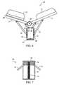
- an orthosis 160 of the present inventionincludes a first pair of arm members 162 and 164 attachable to the first body portion and a second pair of arm members 166 and 168 attachable to the second body portion, wherein the joint axis 170 is interposed between the first and second arm member pairs 162 , 164 , 166 , and 168 .
- the first and second arm member pairs 162 , 164 , 166 , and 168are pivotally connected with each other on the joint axis 170 .
- the first pair of arm members 162 and 164include attachment brackets 172 and 174 attach there to.
- a first cuff 178is attached to the attachment brackets 172 and 174 , wherein the first cuff 178 is positionable about the first body portion.
- the first cuff 178is attached to the first body portion by cuff straps.
- the first cuff 178secures the first body portion to the first pair of arm members 162 and 164 .
- the second pair of arm members 166 and 169include attachment brackets 180 and 182 attach there to.
- a second cuff 184is attached to the attachment brackets 180 and 182 , wherein a force application assembly 18 is interposed between the attachment brackets 180 and 182 and the second cuff 184 .
- the second cuff 184is positionable about the second body portion and is attached to the second body portion by cuff straps, such that the force application assembly 18 can provide a constant force to the second body portion.
- a drive assembly 188is connected to and interposed between the first arm member 164 and the second arm member 168 .
- the drive assembly 188includes a housing 190 connected to first arm member 164 .
- the housing 190includes a worm 192 mounted therein and operably connected to a knob 194 .
- a rotation of the knob 194rotates the worm 192 .
- a main gear 196is rotatably mounted to the housing 190 , where the main gear 196 rotates about the joint axis 170 .
- the main gear 196is mounted in engagement with the worm 194 , such that as the worm 194 is rotated the main gear 196 is rotated.
- Second arm member 168is affixed to the main gear 196 , such that as the main gear 196 is rotated the second arm member 168 is rotated about the joint axis with respect to the first arm member 164 ,
- the drive assembly 188 for an orthosis 160 in accordance with the present inventioncan be actuated by a motor instead of by a manually actuatable member, such as the knob 194 .
- a compressive forcemay be applied to the connective tissue surrounding the joint. It may be desirable to control the compressive force, distracting the joint as the joint is flexed or extended. “Distraction” is defined by one dictionary as “Separation of the surfaces of a joint by extension without injury or dislocation of the parts.” (Taber's Cyclopedic Medical Dictionary, 16th Edition, 1989, page 521), and involves stretching rather than compressing the joint capsule, soft tissue, ligaments, and tendons.
- the orthosis 30includes two relatively pivotable arm members 12 and 14 .
- Each arm member 12 and 14includes a cuff 31 and 32 mounted there to, where the first cuff 31 is slidably mounted to the first arm member 12 and the second cuff 32 is slidably mounted to the force application assembly 18 .
- the cuffs 31 and 32clamp onto the body portions on either side of the joint.
- the pivot axis “P” of the arm member 12 and 14is spaced from the axis of rotation of the joint. Movement of the arm member 12 and 14 to extend the joint may result in distractive forces being applied to the joint. These distractive forces are limited and controlled by having the cuffs 31 and 32 slidable on the arm members 12 and 14 .
- the cuffs 31 and 32are selectively moved along the arm member 12 and 14 , during relative movement of the arm member 12 and 14 , to provide the proper amount of distractive forces to the joint and to limit compressive forces on the joint.
- the orthosis 190includes a first arm member 12 attachable to a first body portion and a second arm member 14 attachable to a second body portion.
- the orthosis 190further includes a first force application assembly 18 a connected to the first arm member 12 .
- the first force application assembly 18 amay be positioned between the first arm member 12 and the first body portion, such that the first force application assembly 18 a provides a substantially constant force to the first body portion
- a second force application assembly 18 bconnected to the second arm member 14 .
- the second force application assembly 18 bmay be positioned between the second arm member 14 and the second body portion, such that the second force application assembly 18 b provides a substantially constant force to the second body portion.
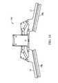
- the orthosis 220includes first and second arm member 222 and 224 pivotally connected to a base member 226 .
- a control assembly 228is mounted to the base member 226 proximal to the first and second arm members 222 and 224 .
- the first arm member 222is operably connected to the control assembly 228 with a first lever arm 230 and the second arm member 224 is operable connected to the control assembly 228 with a second lever arm 232 , such that an operation of the control assembly pivots the first and second lever arms 222 and 224 about the base member 226 .
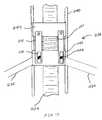
- the control assembly 228includes a drive assembly 234 and an integrated force application assembly 236 .
- the drive assembly 234includes a thread member 238 rotatably mounted in a control frame 240 , where a first end of the threaded member 238 in rotatably connected to the base member 226 and a second end of the threaded member 238 is connected to a knob 242 , such that a rotation of the knob 242 rotates the threaded member 238 .
- a threaded bushing 244is slidably mounted in the control frame 240 about the threaded member 238 , such that rotation of the threaded member 238 causes the threaded bushing 244 to traverse the threaded member 238 .
- the force application assembly 236is integrated to the drive assembly 234 and includes a slip bushing 246 slidably mounted in the control frame 240 about the threaded member 238 .
- the slip bushing 246is movably connected to the threaded bushing 244 with elongated connectors 248 , where a first end of the elongated connectors 238 are affixed to the threaded busing 244 .
- a second end of the elongated connectors 248includes slotted portions 250 configured to receive pin members 252 affixed to the slip bushing 246 , such that the slip bushing 246 can move with respect to the threaded bushing 244 along the slotted portions 250 .
- the first and second lever arms 230 and 232are pivotally connected to the slip bushing 246 .
- a force element 254such as a spring, is interposed between the threaded bushing 244 and the slip bushing 246 .
- the knob 242may be turned to rotate the threaded member 226 such that the threaded bushing 244 and the slip bushing 246 move, either upward or downward along the threaded member 226 .
- the slip bushing 224applies a directed force to the first and second lever arms 230 and 232 . This force is transmitted to the first and second arm members 222 and 224 , pivoting the first and second arm members 222 and 224 with respect to the base member 226 .
- the orthosis 220is operated to extend a joint in the following manner.
- the first arm member 22is fastened to the first body portion and the second arm member 224 is fastened to the second body portion.
- the orthosis 220is attached to the first and second body portions in a first position.
- the drive assembly 234is operated to move the second arm member 224 from the first position to a second position, relative to the first arm member 222 .
- the connective tissue of the jointis consequently stretched.
- the orthosis 220is maintained in the second position for a predetermined treatment time, utilizing the principles of stress relaxation to stretch the connective tissue of the joint.
- the present inventionfurther utilizes a force application assembly 236 to apply loading or forces to the second body portion. This application of force prevents a relaxation of the connective tissue of the joint, utilizing the principles of creep to further stretch the connective tissue of the joint.
- the force applied by the force application assembly 236may be less than a force applied by the drive assembly 234 , such that the force element 254 is compressed between the threaded bushing 244 and the slip bushing 246 .
- the drive assembly forcemay decrease to a point where the force application assembly force exceeds the drive assembly force, such that the force element 254 expanded, moving the slip bushing 236 with respect the threaded bushing 244 , providing a force to the tissue.
- the force application assembly 238can impart a substantially constant force onto the second body portion.
- the application of the force application assembly forceutilizes the principals of creep to continuous stretch the joint tissue during the set time period, maintain, decreasing, or preventing a relaxation of the tissue.
- the drive assembly 234may be used to move the second arm member 224 with respect to the first arm member 222 from the second position to a third position, incrementally stretching the tissue surrounding the joint. It is contemplated that the drive assembly 234 may be used to incrementally move the second body portion after the expiration of a predetermined time or until completion of the protocol.
- the orthosis 220can further include a second force application assembly 260 .
- the force application assembly 260can take the form as those previously described herein.
- the force application assembly 260includes an assembly member 262 pivotally connected to the first arm member 222 , such that the assembly member 262 is interposed between the first arm member 222 and the first body portion.
- One or more force elements 264such as a spring, is interposed between the first arm member 222 and the assembly member 262 , where the force element 264 provides a force urging the assembly member 262 away from the first arm member 222 .
- the force applied by the force application assemblies 236 and 260may be less than a force applied by the drive assembly 234 .
- the drive assembly forcemay decrease to a point where the force application assembly force exceeds the drive assembly force, such that the force application assemblies 236 and 260 can provide a force to the tissue.
- the force application assemblies 236 and 260can impart a substantially constant force onto the second body portion.
- the application of the force application assembly forcesutilizes the principals of creep to continuous stretch the joint tissue during the set time period, maintiain, decreasing, or preventing a relaxation of the tissue.
- the drive assembly 16may be used to move the second arm member 14 with respect to the first arm member 12 from the second position to a third position, incrementally stretching the tissue surrounding the joint. It is contemplated that the drive assembly 12 may be used to incrementally move the second body portion after the expiration of a predetermined time or until completion of the protocol.
- a compressive or distractive forcemay be applied to the connective tissue surrounding the joint.
- the compressive or distractive forcemay be controlled by slidably mounting the cuffs to the arm members.
- the arm memberscan be expandable to adsorb the compressive and distractive forces imparted in the joint.
- arm member 12 or 14may include a telescoping rod 278 having a first portion 280 slidably mounted onto a second portion 282 .
- Each arm member 12 or 14can include a cuff 31 or 32 mounted to the first portion 280 , where the cuff 31 or 32 clamps onto a body portion on either side of the joint. Movement of the arm member 12 or 14 to extend the joint may result in distractive forces being applied to the joint. These distractive forces are limited and controlled by the first member 280 sliding on the second member 282 .
- the first member 280is selectively moved along the second member 282 , during relative movement of the arm member 12 or 14 , to provide the proper amount of distractive forces to the joint and to limit compressive forces on the joint.
- the telescoping rod 278can be used to adjust the length of the arm member 12 or 14 . Adjustment of the arm member 12 or 14 enables the orthosis to be better tailored to a user's anatomy.
- a spring 284can be interposed between the first and second portions 280 and 282 .
- the spring 284can provide a distractive force to the joint.
- the amount of force applied by the springcan be controlled using a control mechanism.
- the control mechanismcan include a threaded member 286 which can be used to increase or decrease the applied force.
- the spring 284provides a distractive force
- expanding the telescoping rod 278imparts a moment force about the joint axis.
- the momentimparts a substantially constant force to the first and second arm members 12 and 14 and the second body portion, utilizing the principles of creep to further stretch the joint tissue.
- the orthosis of the present inventioncan be used to extend, flex, or rotate other joints in the body, such as an ankle, knee, finger, wrist, or elbow joint, with the construction of the orthosis in such case being varied to fit the particular application.
- the orthosiscan be used, for example, to flex the ankle joint to stretch a tight achilles tendon in cerebral palsy or post traumatic contractures. It may also be especially useful in obtaining the last degrees of joint extension.
- the orthosiscan be custom made to fit a particular individual, or can be an off the shelf item.
- the orthosiscan also be used, for example, to eliminate contractures or stress soft tissue.
- the inventioncan be used for patients with cerebral palsy, stroke, spastic paralysis, burns, as well as in post-traumatic or post-surgical cases. It can also be used, for example, in therapy after a knee replacement, in which the extremes of motion in extension or flexion are difficult to obtain without extensive intervention of a therapist. As previously discussed, the invention also may be used to extend the rotational capability of a joint.
- the devicecan be used for tissue transport, bone lengthening, stretching skin or tissue fascia, etc.
- device of the present inventioncan be incorporated in an external bone fixation device, such as a llizarov device, where the device is affixed to the bones on the body portions using pins.
- the drive assembly and force application assemblycan be used for bone lengthening and stretch the surround soft tissue.
- the present inventionis disclosed as utilizing the principles of stress relaxation and creep. However, it is contemplated that the present invention can include additional treatment protocols.
- CPMcontinuous passive motion
- the devicecontinually moves the joint through a range of motion.
- the motionmay be provided by an electric or hydraulic motor or a pneumatic system attached to the device. As the CPM moves the joint through its range of motion, however, it does not increase the range of motion.
- the present inventioncan be incorporated into a CPM device, where the CPM device would stop at an end range position.
- a drive assemblymay be provided to move the joint from its normal position at the end range position of the CPM to a second position, thereby stretching the tissue using the principles of stress relaxation.
- a force application assemblymay be utilized to provide an additional force, utilizing the principles of creep to stretch the tissue.
- the drive assemblymay be moved to a third position to further stretch the tissue or the CPM device may resume movement of the joint throughout the range of motion.
- the drive assemblyBefore CPM movement resumes, the drive assembly may be returned to an original position so that the range of motion of the CPM is returned to its original state, or the drive assembly may be used to alter the range of motion that the CPM follows. In this manner CPM device can be utilized to increase the range of motion of the joint.
- the device of the present inventioncan include multiple drive assemblies for providing a macro and micro adjustment of the device.
- FIG. 20another orthosis 300 of the present invention is provided.
- the orthosis 300includes first and second arm members 302 and 304 pivotally connected to a base member 306 .
- a first drive assembly 308is mounted to the base member 306 proximal to the first and second arm members 302 and 304 .
- the first arm member 302is operably connected to the first drive assembly 308 with a first lever arm 310 and the second arm member 304 is operably connected to the first drive assembly 308 with a second lever arm 312 , such that an operation of the first drive assembly 308 pivots the first and second lever arms 302 and 304 about the base member 306 .
- the first drive assembly 308can include a thread member 238 rotatably mounted in a control frame 240 , where a first end of the threaded member 238 in rotatable connected to the base member 306 and a second end of the threaded member 238 is connect to a knob 242 , such that a rotation of the knob 242 rotates the threaded member 238 .
- a threaded bushing 244is slidably mounted in the control frame 240 about the threaded member 238 , such that rotation of the threaded member 238 caused the threaded bushing 244 to traverse the threaded member 238 .
- the first drive assembly 308provides a macro or gross adjustment of the first and second arm members 302 and 304 .
- this drive membermay implement principles of stress relaxation by moving the joint or tissue from a first position to a second position that is maintained while the tissue stretches.
- a second drive assembly 314is mounted to the second arm member 304 .
- the second drive assembly 314includes an assembly member 316 pivotally connected to the second arm member 304 .
- a drive element 318in interposed between the assembly member 316 and the second arm member 304 .
- the drive element 318provides a force to the assembly member 316 and the second arm member 304 , such that the position of the assembly member 316 can be moved and selectively positioned with respect to the second arm member 304 .
- the drive element 318provides a micro or fine adjust to the device and may be used to utilize the principles of creep by imparting forces to the joint while the first drive assembly 308 is held in a fixed position.
- the second drive assemblymay impart loading on the tissue or joint. This loading can be provided by monitoring resistive forces of the tissue and adjusting the device to maintain a desired loading condition. Thus, over time the position of the second drive assembly may change while the position of the first drive assembly remains fixed. If the first drive assembly is subsequently moved to a third position, the second drive assembly may also be repositioned to an original or starting position with respect to the second arm member 304 .
- the drive element 318can include a threaded member 320 threaded through the second arm member 304 .
- a first end of the threaded member 320contact a bottom surface of the assembly member 316 .
- a second end of the threaded member 320includes a knob 322 , a rotation of which threaded the threaded member 320 through the second arm member 304 changes the position of the assembly member 316 with respect to the second arm member 304 .
- the drive element 318can be a gear system or pneumatic device positioned between the assembly member 316 and the second arm member 304 .
- the gear system or pneumatic devicecan provide a force to change the position of the assembly member 316 with respect to the second arm member 304 .
- first and second arm membersare shown being connected by a simple connector, pivoting about a singly axis.
- the s first and second arm membercan be connect by a complex connector, allowing rotation about multiple axis.
- the complex connectcan be a ball and socket type joint, a universal joint, or other similar type joints.
- neck brace 400can be used to move or stabilize a neck of a patient.
- the neck brace 400includes a T-shaped support member 402 which is connected with a torso 404 of a person.
- a chin support 406is connected with a chin of the person.
- An actuator mechanism 408moves the chin support 406 relative to the support member 402 .
- the chin support 406is moved relative to the support member 402 after the chin support is connected to the chin and the support member is connected to the torso 404 to move the neck of the person.
- the support member 402 and the chin support 406may have any desired construction as long as they are effective to engage the torso 404 and the chin.
- a pair of interconnecting members or arms 410connects the chin support 406 with the support member 402 .
- the arms 410extend from the chin support 406 to the actuator mechanism 408 .
- Each of the arms 410has an upper end 412 with a slot 414 .
- Threaded members 416extend from the portion 418 of the chin support 406 through the slots 414 .
- Clamping members 420threadably engage the threaded members 416 to clamp the ends 412 of the arms 410 to the portion 418 .
- the portion 418can be positioned relative to the arms 410 when the clamping members 420 are loosened from the threaded members 416 .
- the portion 418can be pivoted about the threaded members 416 and the threaded members can be moved between the ends of the slots 414 to position the chin support 406 relative to the arms 410 .
- the actuator mechanism 408is connected to a pivot support 422 connected to a support plate 424 of the support member 402 .
- the actuator mechanism 408is connected to the pivot support by a pivot connection 426 .
- the actuator mechanism 408transmits force between the support member 402 and the chin support 406 to simultaneously pivot the actuator mechanism about a pivot axis of the pivot connection 426 and move the interconnecting members 410 relative to the actuator mechanism.
- the actuator mechanism 408transmits force from an input member which, in the illustrated embodiment of the neck brace 400 , is a manually rotatable knob 428 . Force is transmitted from the knob 428 through the actuator mechanism 408 to the chin support 406 . Force is transmitted from the actuator mechanism 408 to pivot the actuator mechanism about the pivot connection 426 . In addition, force is transmitted from the knob 428 to move the interconnecting members 410 and the chin support 406 relative to the actuator mechanism 408 as the actuator mechanism pivots about the pivot connection 426 .
- the neck brace 400is more fully described in U.S. Pat. No. 6,503,213, entitled Method of Using a Neck Brace, to Bonutti, the entire contents of which are herein incorporated by reference in its entirety.
- the interconnecting arms 410further include a force application assembly 430 .
- the arms 410are bisected into first and second portions 432 and 434 , where the force application assembly 430 is interposed between the first and second portions 432 and 434 .
- the force application assembly 430can provided a force to the second portion 434 with respect to the first portion 432 , such that a distractive force can be applied to the neck of the patient.
- the distractive forceprovides a cervical traction to the neck of the patient, separating the vertebrae.
- the force application assemblycan include a spring portion, bladder or other such mechanism. Additionally, the applied force can be selectively controlled, where the magnitude of the applied force can be increased or decreased by the patient, medical practitioner, or others.
- the components of the present inventionare rigid members made of, for example, aluminum, stainless steel, polymeric, or composite materials.
- the member and extensionsare rigid so as to be able to transmit the necessary forces. It should be understood that any material of sufficient rigidity can be used.
- the componentscan be made by injection molding.
- tool and die metal molds of the componentsare prepared. Hot, melted plastic material is injected into the molds. The plastic is allowed to cool, forming components. The components are removed from the molds and assembled.
- the componentscan be made of polymeric or composite materials such that the device can be disposable.
- the componentscan be made of a biodegradable material such as a biodegradable polymer.
- a biodegradable materialsuch as a biodegradable polymer.
- PHA'spoly (hydroxyacids)
- PLApolyactic acid
- PGApolyglycolic acid
- the devicecan be made of a nonmagnetic material.
- the devicecan be used as a positioning device for use in imaging devices, such as a MRI device. It is also contemplated that the device can be used as a positioning device for use during surgical procedures, where it may be necessary to adjust and hold the position of the joint.
Landscapes
- Health & Medical Sciences (AREA)
- General Health & Medical Sciences (AREA)
- Veterinary Medicine (AREA)
- Public Health (AREA)
- Life Sciences & Earth Sciences (AREA)
- Animal Behavior & Ethology (AREA)
- Physical Education & Sports Medicine (AREA)
- Rehabilitation Therapy (AREA)
- Pain & Pain Management (AREA)
- Epidemiology (AREA)
- Orthopedic Medicine & Surgery (AREA)
- Engineering & Computer Science (AREA)
- Biomedical Technology (AREA)
- Nursing (AREA)
- Heart & Thoracic Surgery (AREA)
- Vascular Medicine (AREA)
- Neurology (AREA)
- Orthopedics, Nursing, And Contraception (AREA)
Abstract
Description
Claims (35)
Priority Applications (4)
| Application Number | Priority Date | Filing Date | Title |
|---|---|---|---|
| US11/203,516US8012108B2 (en) | 2005-08-12 | 2005-08-12 | Range of motion system and method |
| US13/194,496US8784343B2 (en) | 2005-08-12 | 2011-07-29 | Range of motion system |
| US14/311,879US9320669B2 (en) | 2005-08-12 | 2014-06-23 | Range of motion system |
| US15/071,344US20160331621A1 (en) | 2005-08-12 | 2016-03-16 | Range of Motion System and Method |
Applications Claiming Priority (1)
| Application Number | Priority Date | Filing Date | Title |
|---|---|---|---|
| US11/203,516US8012108B2 (en) | 2005-08-12 | 2005-08-12 | Range of motion system and method |
Related Child Applications (1)
| Application Number | Title | Priority Date | Filing Date |
|---|---|---|---|
| US13/194,496DivisionUS8784343B2 (en) | 2005-08-12 | 2011-07-29 | Range of motion system |
Publications (2)
| Publication Number | Publication Date |
|---|---|
| US20070038161A1 US20070038161A1 (en) | 2007-02-15 |
| US8012108B2true US8012108B2 (en) | 2011-09-06 |
Family
ID=37743469
Family Applications (4)
| Application Number | Title | Priority Date | Filing Date |
|---|---|---|---|
| US11/203,516Active2026-03-18US8012108B2 (en) | 2005-08-12 | 2005-08-12 | Range of motion system and method |
| US13/194,496Active2025-12-02US8784343B2 (en) | 2005-08-12 | 2011-07-29 | Range of motion system |
| US14/311,879Expired - LifetimeUS9320669B2 (en) | 2005-08-12 | 2014-06-23 | Range of motion system |
| US15/071,344AbandonedUS20160331621A1 (en) | 2005-08-12 | 2016-03-16 | Range of Motion System and Method |
Family Applications After (3)
| Application Number | Title | Priority Date | Filing Date |
|---|---|---|---|
| US13/194,496Active2025-12-02US8784343B2 (en) | 2005-08-12 | 2011-07-29 | Range of motion system |
| US14/311,879Expired - LifetimeUS9320669B2 (en) | 2005-08-12 | 2014-06-23 | Range of motion system |
| US15/071,344AbandonedUS20160331621A1 (en) | 2005-08-12 | 2016-03-16 | Range of Motion System and Method |
Country Status (1)
| Country | Link |
|---|---|
| US (4) | US8012108B2 (en) |
Cited By (6)
| Publication number | Priority date | Publication date | Assignee | Title |
|---|---|---|---|---|
| US20150105222A1 (en)* | 2007-08-15 | 2015-04-16 | Grigore C. Burdea | Rehabilitation systems and methods |
| US20170281386A1 (en)* | 2016-03-30 | 2017-10-05 | Albert Rojo Salido, III | Finger Splint for Treating Boutonniere Deformity |
| US10278881B1 (en) | 2013-12-12 | 2019-05-07 | Ermi, Inc. | Devices and methods for assisting pronation and/or supination |
| US11136234B2 (en) | 2007-08-15 | 2021-10-05 | Bright Cloud International Corporation | Rehabilitation systems and methods |
| US11896538B2 (en)* | 2013-03-15 | 2024-02-13 | Ermi, Inc. | Device with therapeutic features |
| US20240082094A1 (en)* | 2015-03-04 | 2024-03-14 | Bonutti Research, Inc. | Orthosis for range of motion |
Families Citing this family (31)
| Publication number | Priority date | Publication date | Assignee | Title |
|---|---|---|---|---|
| US6113562A (en) | 1998-06-01 | 2000-09-05 | Peter M. Bonutti | Shoulder orthosis |
| US6502577B1 (en)* | 2000-09-18 | 2003-01-07 | Peter M. Bonutti | Method for moving finger joints |
| US6503213B2 (en)* | 2000-12-01 | 2003-01-07 | Peter M. Bonutti | Method of using a neck brace |
| US6575926B2 (en)* | 2000-12-15 | 2003-06-10 | Bonutti 2003 Trust-A | Myofascial strap |
| US7182738B2 (en) | 2003-04-23 | 2007-02-27 | Marctec, Llc | Patient monitoring apparatus and method for orthosis and other devices |
| US7452342B2 (en) | 2004-03-08 | 2008-11-18 | Bonutti Research Inc. | Range of motion device |
| US8066656B2 (en) | 2005-10-28 | 2011-11-29 | Bonutti Research, Inc. | Range of motion device |
| US8012108B2 (en) | 2005-08-12 | 2011-09-06 | Bonutti Research, Inc. | Range of motion system and method |
| US8920346B2 (en) | 2007-02-05 | 2014-12-30 | Bonutti Research Inc. | Knee orthosis |
| US8353854B2 (en) | 2007-02-14 | 2013-01-15 | Tibion Corporation | Method and devices for moving a body joint |
| EP2178475A1 (en)* | 2007-07-25 | 2010-04-28 | Bonutti Research Inc. | Orthosis apparatus and method of using an orthosis apparatus |
| US8905950B2 (en) | 2008-03-04 | 2014-12-09 | Bonutti Research, Inc. | Shoulder ROM orthosis |
| US20090306548A1 (en)* | 2008-06-05 | 2009-12-10 | Bhugra Kern S | Therapeutic method and device for rehabilitation |
| CA2823606C (en)* | 2011-02-11 | 2018-10-16 | Orthofix S.R.L. | External orthopaedic fixator for the elbow joint. |
| CN102764188B (en)* | 2012-07-16 | 2014-04-02 | 上海大学 | Controllable variable-stiffness flexible elbow joint rehabilitation robot |
| US10292887B2 (en)* | 2012-12-31 | 2019-05-21 | Mako Surgical Corp. | Motorized joint positioner |
| US9402759B2 (en) | 2013-02-05 | 2016-08-02 | Bonutti Research, Inc. | Cervical traction systems and method |
| WO2014151584A1 (en) | 2013-03-15 | 2014-09-25 | Alterg, Inc. | Orthotic device drive system and method |
| US20160002780A1 (en)* | 2013-03-15 | 2016-01-07 | Applied Materials, Inc. | Carrier for substrates |
| WO2016069713A1 (en)* | 2014-10-29 | 2016-05-06 | Bonutti Research, Inc. | Orthosis for range of motion |
| US11273069B2 (en) | 2016-01-12 | 2022-03-15 | The Trustees Of Columbia University In The City Of New York | Wearable apparatuses, methods, and systems for diagnosis, analysis, therapy and other uses |
| US9867752B2 (en)* | 2016-02-19 | 2018-01-16 | Beto Engineering & Marketing Co., Ltd. | Tilting inversion exerciser |
| US11241353B2 (en) | 2017-11-09 | 2022-02-08 | The Curators Of The University Of Missouri | Knee flexion device and associated method of use |
| US11844738B2 (en) | 2018-08-17 | 2023-12-19 | Troy Bruesewitz | Therapy device for neck and spine |
| CN109199796A (en)* | 2018-10-29 | 2019-01-15 | 西安交通大学医学院第附属医院 | A kind of pneumatic electromagnetic levitation type recovery set for lower limbs |
| US11324654B2 (en)* | 2019-09-05 | 2022-05-10 | Leaders Rehab Robot | Rehabilitation device |
| JP7202474B2 (en)* | 2019-11-15 | 2023-01-11 | エイチ ロボティクス インコーポレイテッド | Rehabilitation exercise device for upper and lower limbs |
| WO2021096131A1 (en)* | 2019-11-15 | 2021-05-20 | 에이치로보틱스 주식회사 | Rehabilitation exercise device for upper and lower limbs |
| WO2022234572A1 (en)* | 2021-05-03 | 2022-11-10 | Skelable Ltd. | Dynamic orthosis |
| WO2022267832A1 (en)* | 2021-06-21 | 2022-12-29 | 苏州微创康复医疗科技(集团)有限公司 | Tissue adjusting device |
| US11857447B1 (en) | 2023-03-21 | 2024-01-02 | Robert MacArthur | Brace for reducing and stabilizing fracture in human hand |
Citations (262)
| Publication number | Priority date | Publication date | Assignee | Title |
|---|---|---|---|---|
| US433227A (en) | 1890-07-29 | Thirds to charles it | ||
| DE405327C (en) | 1924-03-19 | 1924-10-31 | Fritz Groenert | Stretching device to remedy shortened tendons |
| US2191283A (en) | 1938-07-02 | 1940-02-20 | Harry H Leiter | Splint |
| US2206902A (en) | 1935-04-29 | 1940-07-09 | Kost Alwin | Foot corrective device |
| US2223276A (en) | 1937-12-17 | 1940-11-26 | Thomas C Ward | Cervical splint |
| US2237252A (en) | 1939-09-27 | 1941-04-01 | Harry Herschel Leiter | Surgical arm rest and support therefor |
| US2246689A (en) | 1938-05-09 | 1941-06-24 | Kost Alwin | Mechanical movement |
| US2250493A (en) | 1940-06-10 | 1941-07-29 | George M Milne | Foot and leg exercising device |
| US2590739A (en) | 1949-07-26 | 1952-03-25 | Wagner Hugo | Orthopedic bone aligning and fixing mechanism |
| US2590729A (en) | 1948-06-16 | 1952-03-25 | Scognamillo Engineering Compan | Rotary compressor |
| US2811154A (en) | 1953-07-20 | 1957-10-29 | William M Scholl | Stretchable bandage |
| US2820455A (en) | 1953-12-28 | 1958-01-21 | Newton J Hall | Neck brace |
| US2829562A (en) | 1953-02-03 | 1958-04-08 | Rue Richard M La | Cartridge feeding mechanism |
| US2832334A (en) | 1956-05-23 | 1958-04-29 | Stephen H Whitelaw | Therapeutic device for use in manipulative treatment of joints of the human body |
| US3083708A (en) | 1960-08-08 | 1963-04-02 | Jobst Institute | Sleeve or legging for stimulating flow of fluids within an animal body |
| US3338237A (en) | 1964-10-20 | 1967-08-29 | Sconce Jerry Wayne | Pneumatic splint |
| US3351055A (en) | 1963-11-26 | 1967-11-07 | Jobst Institute | Pressure bandage-splint and method of forming same |
| US3548818A (en) | 1968-03-14 | 1970-12-22 | David Kaplan | Shoulder brace |
| US3580248A (en) | 1968-12-02 | 1971-05-25 | Leighton W Larson | Bivalved cast |
| US3698389A (en) | 1971-05-21 | 1972-10-17 | Guedel Co Inc | Elbow locking device |
| US3701349A (en) | 1971-05-13 | 1972-10-31 | Leighton W Larson | Bi-valved cast |
| US3724452A (en) | 1971-03-04 | 1973-04-03 | Green T | Cervical brace |
| US3760056A (en) | 1970-09-23 | 1973-09-18 | Bogert R | Method for custom fitting an inflatable bladder to a wearer{3 s foot |
| US3795243A (en) | 1973-01-29 | 1974-03-05 | J Miller | Ambulatory traction device for cervical problems |
| US3811434A (en) | 1972-10-26 | 1974-05-21 | Jacobson S Mfg | Inflatable splint |
| US3814419A (en) | 1973-06-04 | 1974-06-04 | L Bjorklund | Arm exercising device |
| US3856004A (en) | 1973-12-26 | 1974-12-24 | Comfort Care Prod | Clavicle brace |
| US3955565A (en) | 1973-12-05 | 1976-05-11 | Johnson Jr Glenn W | Orthopedic apparatus |
| US3970316A (en) | 1975-03-27 | 1976-07-20 | Diversified Products, Inc. | Golf swing restrictor |
| US3976057A (en) | 1974-12-23 | 1976-08-24 | Clarence F. Bates | Joint flexing apparatus |
| US4039183A (en) | 1976-04-21 | 1977-08-02 | Ritshyo Kogyo Kabushiki Kaisha | Wrist exercise and strengthening device |
| US4076022A (en) | 1976-12-20 | 1978-02-28 | James Walker | Therapeutic foot and leg protector |
| US4084267A (en) | 1975-09-18 | 1978-04-18 | Viennatone Gesellschaft M.B.H. | Drive for an orthosis or a prosthesis |
| US4108170A (en) | 1977-03-24 | 1978-08-22 | Spann Donald C | Patient support strap |
| US4180870A (en) | 1975-04-15 | 1980-01-01 | Fa Wilh. Jul. Teufel | Universal-orthese |
| DE2829562A1 (en) | 1978-07-05 | 1980-01-17 | Klaus Muenich | Machine for exercising part of human body - has motor reversing switch actuated by lever coupled to winch drum |
| US4214577A (en) | 1978-02-27 | 1980-07-29 | Hoy Mansell I | Orthosis for exercising joint |
| US4229001A (en) | 1979-02-23 | 1980-10-21 | Roman Michael P | Therapeutic exercise device |
| US4237873A (en) | 1978-12-11 | 1980-12-09 | Hoyt Laurance J Sr | Cerebral palsy arm and hand brace |
| US4241731A (en) | 1978-05-11 | 1980-12-30 | Pauley James H | Universal arm support |
| US4273113A (en) | 1979-10-29 | 1981-06-16 | World Medical Marketing Corporation | Foot exerciser |
| US4285773A (en) | 1977-08-27 | 1981-08-25 | Alberta Oil Sands Technology And Research Authority | Apparatus and process for recovery of hydrocarbon from inorganic host materials |
| US4320748A (en) | 1980-11-20 | 1982-03-23 | Orthomedics, Inc. | Fracture brace |
| US4363481A (en) | 1980-11-20 | 1982-12-14 | Erickson David T | Exercise device |
| US4370977A (en) | 1981-05-04 | 1983-02-01 | Kenneth D. Driver | Knee and elbow brace |
| US4383523A (en) | 1980-06-13 | 1983-05-17 | Schurman John R | Cervical brace |
| US4417569A (en) | 1981-10-19 | 1983-11-29 | Alexander Mencher | Universal functional shoulder orthosis |
| US4441489A (en) | 1981-03-10 | 1984-04-10 | National Research Development Corporation | Orthopaedic splints |
| US4454871A (en) | 1980-09-29 | 1984-06-19 | Med-Con, Inc. | Ankle-foot orthosis |
| US4456001A (en) | 1982-07-02 | 1984-06-26 | Electro-Biology, Inc. | Apparatus for equine hoof treatment |
| US4456002A (en) | 1982-09-27 | 1984-06-26 | L M B Hand Rehab Products | Spring metacarpophalangeal flexion splint (knuckle splint) |
| US4502681A (en) | 1980-08-08 | 1985-03-05 | Olle Blomqvist | Apparatus for carrying out quadriceps training |
| US4502470A (en) | 1982-09-16 | 1985-03-05 | Kiser John L | Physiologic device and method of treating the leg extremities |
| US4508111A (en) | 1981-07-23 | 1985-04-02 | Dynasplint Systems, Inc. | Adjustable splint |
| US4509509A (en) | 1983-07-11 | 1985-04-09 | Jean Bouvet | Apparatus for treating the joints of the human body |
| SU1158195A1 (en) | 1983-09-20 | 1985-05-30 | 9-Я Городская Клиническая Больница Г.Запорожья | Apparatus for developing contractures of upper limb |
| US4538595A (en) | 1984-02-21 | 1985-09-03 | Hajianpour Muhamad A | Passive exercising device |
| US4538600A (en) | 1983-10-27 | 1985-09-03 | Dynasplint Systems, Inc. | Adjustable splint |
| US4570619A (en) | 1982-10-27 | 1986-02-18 | Jung Corporation | Clavicle brace |
| US4576151A (en) | 1984-03-19 | 1986-03-18 | Carmichael Hoagy C | Orthopedic leg appliance |
| US4589406A (en) | 1983-08-11 | 1986-05-20 | Florek Florian F | Orthopaedic appliance for use in treating acromioclavicular joint injuries |
| EP0181688A2 (en) | 1984-10-30 | 1986-05-21 | SEGAL, David | Limb exerciser |
| US4612919A (en) | 1984-10-03 | 1986-09-23 | Best Walter E | Adjustable limb support |
| US4628913A (en) | 1984-01-13 | 1986-12-16 | United States Manufacturing Co. | Cervical thoracic orthosis |
| US4641639A (en) | 1985-12-09 | 1987-02-10 | Rigoberto Padilla | Ambulatory brace assembly |
| US4653479A (en) | 1985-01-17 | 1987-03-31 | Empi, Inc. | Interrupted drive limb motion apparatus |
| US4665905A (en) | 1986-06-09 | 1987-05-19 | Brown Charles S | Dynamic elbow and knee extension brace |
| US4693239A (en) | 1986-01-21 | 1987-09-15 | Orthomedics, Inc. | Orthosis |
| US4716889A (en) | 1981-10-23 | 1988-01-05 | Toronto Medical Corp. | Device for imparting continuous passive motion to human joints |
| US4718665A (en) | 1986-07-15 | 1988-01-12 | Soma Dynamics Corporation | Exercise device |
| US4727865A (en) | 1985-03-07 | 1988-03-01 | Hill Byrne Christopher R | Replaceable rigid cast with integral fasteners |
| US4739334A (en) | 1986-09-30 | 1988-04-19 | The United States Of America As Represented By The Secretary Of The Air Force | Electro-optical beamforming network for phased array antennas |
| US4765320A (en) | 1987-05-11 | 1988-08-23 | Smith & Nephew Rolyan, Inc. | Dynamic low profile splint |
| SU1426580A1 (en) | 1987-02-04 | 1988-09-30 | Научно-исследовательский институт травматологии и ортопедии | Arrangement for mechanotherapy of fingers of the hand |
| US4788941A (en) | 1987-05-14 | 1988-12-06 | Villeneuve Gerald P | Safety belt |
| US4790301A (en) | 1987-10-23 | 1988-12-13 | Krister Silfverskiold | Device for and method of dynamic splinting |
| US4793334A (en) | 1986-07-22 | 1988-12-27 | Mcguinness Charles G | Cervical brace |
| US4805601A (en) | 1985-03-15 | 1989-02-21 | Eischen Sr Clement G | Device for lower limb extremity having weight-response pressure chambers |
| US4807601A (en) | 1985-12-20 | 1989-02-28 | Empi, Inc. | Live display appartus for setting extenson and flexion limits in continuous passive motion (CPM) system |
| US4809688A (en) | 1986-04-22 | 1989-03-07 | Empresa Cubana Importadora Y. Exportadora Of Products Medicos, T/A Medicuba | Sinergic splint for early mobilization of the flexor tendons of the hand |
| US4834073A (en)* | 1987-02-20 | 1989-05-30 | Medical Technology, Inc. | Passive motion exerciser |
| US4844455A (en) | 1987-12-21 | 1989-07-04 | Har-Tru Corporation | Tennis net tightening apparatus |
| US4844454A (en) | 1988-07-15 | 1989-07-04 | Rogers Stephen A | Portable, manually operable knee exerciser |
| US4844094A (en) | 1987-05-29 | 1989-07-04 | Royce Medical Company | Ankle brace |
| US4848326A (en) | 1988-06-20 | 1989-07-18 | Robert Lonardo | Knee contracture correction device |
| EP0181668B1 (en) | 1984-11-02 | 1989-08-09 | North American Philips Corporation | Method and apparatus for measuring the apparent frequency shift of ultrasound pulses in tissue |
| US4862877A (en) | 1987-11-18 | 1989-09-05 | Lmb Hand Rehab Products, Inc. | Hand splint for wrist support with optional support of MP joints and thumb and IP finger assists |
| US4865024A (en) | 1988-10-21 | 1989-09-12 | Hensley Dvid E | Extension deceleration orthosis |
| US4869267A (en) | 1988-05-10 | 1989-09-26 | Royce Medical Company | Adjustable tension ankle support |
| US4869499A (en) | 1989-01-17 | 1989-09-26 | Schiraldo Donald R | Toe exercise device |
| US4884454A (en) | 1988-11-14 | 1989-12-05 | Lifting Technologies, Inc. | Manbasket testing apparatus and method |
| US4913755A (en) | 1988-03-16 | 1990-04-03 | Royce Medical Company | Method of forming orthopaedic gel pads |
| US4913135A (en) | 1986-12-16 | 1990-04-03 | Mattingly Leslie G | Cervical brace |
| US4930497A (en) | 1989-01-23 | 1990-06-05 | Toronto Medical Corp. | Apparatus for imparting continuous passive motion to a lower limb |
| US4953543A (en) | 1988-08-09 | 1990-09-04 | Royce Medical Company | Cruciate ligament leg brace |
| US4955396A (en) | 1988-02-05 | 1990-09-11 | Northwest Marine Technology, Inc. | Method for tagging macro-organisms |
| US4955369A (en) | 1988-10-27 | 1990-09-11 | Bledsoe Gary R | Dynamically shiftable counter shear force knee brace |
| US4957281A (en) | 1989-01-30 | 1990-09-18 | Wright State University | Rotator cuff therapeutic exercise apparatus |
| US4964402A (en) | 1988-08-17 | 1990-10-23 | Royce Medical Company | Orthopedic device having gel pad with phase change material |
| US4991234A (en) | 1989-10-10 | 1991-02-12 | Bert Greenberg | Body support band |
| US4996979A (en) | 1989-10-13 | 1991-03-05 | Royce Medical Company | Soft-goods type, formable orthopaedic cast |
| US5005563A (en) | 1990-06-18 | 1991-04-09 | Veale Charles J | Mobile-cervical extension and supporting apparatus |
| US5019050A (en) | 1989-05-30 | 1991-05-28 | Lynn Karen K | Securing device and method |
| US5018514A (en) | 1987-06-11 | 1991-05-28 | Brace Technologies, Inc. | Knee brace |
| US5025782A (en) | 1990-02-12 | 1991-06-25 | Ambulatory Traction Inc. | Adjustable rack and pinion knee brace |
| US5027802A (en) | 1989-06-16 | 1991-07-02 | Donohue Patrick T | Multi-mode digital traction system |
| US5027801A (en) | 1987-05-29 | 1991-07-02 | Royce Medical Company | Orthopaedic gel pad assembly |
| US5027688A (en) | 1988-05-18 | 1991-07-02 | Yamaha Corporation | Brace type angle-detecting device for musical tone control |
| US5036838A (en) | 1990-07-16 | 1991-08-06 | Applied Technology International, Ltd. | Foam plastic orthopedic fabric |
| US5036837A (en) | 1990-02-09 | 1991-08-06 | Bio-Tec, Inc. | Dynamic extension splint |
| SU1671296A1 (en) | 1988-11-21 | 1991-08-23 | Ленинградский научно-исследовательский детский ортопедический институт им.Г.И.Турнера | Orthopedic appliance for upper limb |
| US5052375A (en)* | 1990-02-21 | 1991-10-01 | John G. Stark | Instrumented orthopedic restraining device and method of use |
| US5070866A (en) | 1990-10-25 | 1991-12-10 | Alexander William K | Woven back support belt with rigidity control |
| US5078128A (en) | 1990-06-27 | 1992-01-07 | Royce Medical Company | Removable leg walker |
| US5088481A (en) | 1990-10-10 | 1992-02-18 | Darco International Inc. | Casted foot medical boot with dual pivot points |
| US5100403A (en) | 1990-06-08 | 1992-03-31 | Smith & Nephew Richards, Inc. | Dynamic elbow support |
| US5102411A (en) | 1990-06-08 | 1992-04-07 | Hotchkiss Robert N | Dynamic elbow support |
| EP0380060A3 (en) | 1989-01-24 | 1992-04-15 | Robert D. Singer | Electronic range of motion apparatus for orthosis, prothesis and cpm machine |
| US5116359A (en) | 1990-12-05 | 1992-05-26 | Moore Joseph L | Head, neck and shoulder therapeutic exercise device |
| US5125400A (en) | 1985-12-16 | 1992-06-30 | Aircast Incorporated | Ankle brace having multiple inflatable aircells |
| US5135470A (en) | 1988-05-25 | 1992-08-04 | Bryan Reeves | Shoulder and back support brace |
| US5139475A (en) | 1990-08-14 | 1992-08-18 | Francis Robicsek | Medical appliance for treating venous insufficiency |
| US5141489A (en) | 1991-07-26 | 1992-08-25 | Sereboff Joel L | Cervical brace |
| US5156589A (en) | 1986-09-05 | 1992-10-20 | Karl Otto Braun Kg | Cohesive bandage |
| US5163451A (en) | 1990-12-19 | 1992-11-17 | Sutter Corporation | Rehabilitation patient positioning method |
| US5167612A (en) | 1990-07-30 | 1992-12-01 | Bonutti Peter M | Adjustable orthosis |
| US5191903A (en) | 1991-06-06 | 1993-03-09 | Donohue Patrick T | Digital traction system |
| US5197942A (en) | 1992-01-13 | 1993-03-30 | Harold Brady | Customized foot orthosis |
| US5201772A (en) | 1991-01-31 | 1993-04-13 | Maxwell Scott M | System for resisting limb movement |
| US5201702A (en) | 1990-04-17 | 1993-04-13 | Mars Suzanne P | Brace for supporting the head in an upright position |
| US5203321A (en) | 1990-12-11 | 1993-04-20 | Sutter Corporation | Passive anatomic ankle-foot exerciser |
| FR2661333B1 (en) | 1990-04-25 | 1993-04-23 | Caruana Patrick | MULTI-JOINT MUSCLE EXERCISE APPARATUS. |
| US5211161A (en) | 1991-01-22 | 1993-05-18 | Compagnie Generale De Materiel Orthopedique | Three axis passive motion exerciser |
| US5213094A (en) | 1990-07-30 | 1993-05-25 | Bonutti Peter M | Orthosis with joint distraction |
| US5213095A (en) | 1991-02-06 | 1993-05-25 | Dague Lawrence M | Coupling apparatus for scuba gear |
| US5218954A (en) | 1992-07-09 | 1993-06-15 | Bemmelen Paul S Van | Arterial assist device and method |
| US5226245A (en) | 1991-09-20 | 1993-07-13 | Lamont William D | Protective boot structure |
| US5232435A (en) | 1992-02-04 | 1993-08-03 | Saul Leibinsohn | Splint |
| US5252102A (en) | 1989-01-24 | 1993-10-12 | Electrobionics Corporation | Electronic range of motion apparatus, for orthosis, prosthesis, and CPM machine |
| US5252101A (en) | 1992-01-24 | 1993-10-12 | Breslow, Morrison, Terzian & Associates, Inc. | Simulated toy commode |
| US5261125A (en) | 1992-01-08 | 1993-11-16 | Rudolph Cartwright | Head impact force diversion system |
| US5277695A (en) | 1991-11-08 | 1994-01-11 | Aircast, Inc. | Adjustable ankle compress |
| US5285773A (en) | 1990-07-30 | 1994-02-15 | Peter M. Bonutti | Orthosis with distraction through range of motion |
| US5297540A (en) | 1992-01-29 | 1994-03-29 | Jace Systems, Inc. | Continuous passive motion orthosis device for a toe |
| US5312322A (en) | 1992-11-02 | 1994-05-17 | The United States Of America As Represented By The Secretary Of The Navy | Three point extension splint to treat flexion contractures about limb synovial hinge joints |
| US5316022A (en) | 1992-08-28 | 1994-05-31 | Schiek Sr James W | Sports belt with cinchable fastener system |
| US5323435A (en) | 1993-07-16 | 1994-06-21 | Combustion Engineering Inc. | Control rod housing support bars with wing assemblies |
| US5328448A (en) | 1993-03-16 | 1994-07-12 | Gray Sr Richard O | Finger joint therapy apparatus |
| US5327882A (en) | 1992-09-03 | 1994-07-12 | Toronto Medical Corp. | Continuous passive motion device |
| USRE34661E (en) | 1988-05-10 | 1994-07-12 | Royce Medical Company | Gel and air cushion ankle brace |
| US5329705A (en) | 1993-02-16 | 1994-07-19 | Royce Medical Company | Footgear with pressure relief zones |
| US5348530A (en) | 1993-07-29 | 1994-09-20 | Royce Medical Company | Pneumatic ankle brace with bladder and pump arrangement |
| US5349956A (en) | 1991-12-04 | 1994-09-27 | Apogee Medical Products, Inc. | Apparatus and method for use in medical imaging |
| US5352216A (en) | 1989-10-26 | 1994-10-04 | Alcare Co., Ltd. | Stretch fabric for medical use |
| US5354260A (en) | 1993-05-13 | 1994-10-11 | Novamedix, Ltd. | Slipper with an inflatable foot pump |
| US5364323A (en) | 1993-09-09 | 1994-11-15 | Tony Liu | Multi-directional rotatable wrist exerciser |
| US5370133A (en) | 1994-02-22 | 1994-12-06 | Darco International, Inc. | Lower leg, ankle and foot immobilization brace with uniform, adjustable compression |
| US5372597A (en) | 1993-05-12 | 1994-12-13 | Smith & Nephew Richards, Inc. | Supination-pronation device |
| US5376091A (en) | 1990-06-08 | 1994-12-27 | Smith & Nephew Richards, Inc. | Dynamic finger support |
| US5378223A (en) | 1992-10-23 | 1995-01-03 | Royce Medical Company | Orthopedic support pad and method for providing semi-permanent relief zones |
| US5385536A (en) | 1993-03-01 | 1995-01-31 | Wayne Z. Burkhead | Orthopedic brace for arm and shoulder |
| US5389065A (en) | 1993-06-15 | 1995-02-14 | Aircast, Inc. | Ankle brace with ATF compression |
| US5391132A (en) | 1992-09-16 | 1995-02-21 | Greenwald; Dale R. | Free standing rotator cuff development device |
| US5399152A (en) | 1990-09-13 | 1995-03-21 | Habermeyer; Peter | Apparatus for treating fractures in extremities |
| US5403265A (en) | 1993-11-03 | 1995-04-04 | Lunax Corporation | Pressure sock |
| US5407422A (en) | 1994-10-04 | 1995-04-18 | Sharon C. Hanson | Pelvic belt |
| US5407420A (en) | 1992-11-12 | 1995-04-18 | Smith & Nephew Donjoy, Inc. | Fully adjustable shoulder brace |
| US5417643A (en) | 1993-10-27 | 1995-05-23 | Danninger Medical Technology, Inc. | Continuous passive motion exercise device |
| US5419757A (en) | 1992-12-28 | 1995-05-30 | Daneshvar; Yousef | Support containing shaped balloons |
| US5421874A (en) | 1993-06-22 | 1995-06-06 | Genesis Composites, L.C. | Composite microsphere and lubricant mixture |
| US5435009A (en) | 1992-10-01 | 1995-07-25 | Huntleigh Technology Plc | Inflatable compression garment |
| US5437611A (en) | 1993-12-01 | 1995-08-01 | Orthotic Rehabilitation Products, Inc. | Dynamic brace joint |
| US5452205A (en) | 1991-09-16 | 1995-09-19 | Jace Systems, Inc. | Universal controller for continuous passive motion devices |
| US5453082A (en)* | 1991-09-20 | 1995-09-26 | Lamont; William D. | Protective medical boot with pneumatically adjustable orthotic splint |
| US5456286A (en) | 1993-08-17 | 1995-10-10 | A. W. Chesterton Co. | Shaft seal coolant flow control |
| US5464385A (en) | 1990-06-27 | 1995-11-07 | Royce Medical Company | Walker with open heel |
| US5466250A (en) | 1991-01-23 | 1995-11-14 | Aircast, Inc. | Automatic fluid compress and circulating system |
| US5466213A (en) | 1993-07-06 | 1995-11-14 | Massachusetts Institute Of Technology | Interactive robotic therapist |
| US5472407A (en) | 1993-10-13 | 1995-12-05 | Schenck; Robert R. | Motorized dynamic traction device |
| US5492133A (en) | 1992-02-19 | 1996-02-20 | Aircast, Inc. | Improved flexible fastening strap |
| US5503622A (en) | 1994-04-18 | 1996-04-02 | Wehr; Maxon P. | Method of making an ankle encompassing pressure orthosis |
| US5503619A (en) | 1990-07-30 | 1996-04-02 | Bonutti; Peter M. | Orthosis for bending wrists |
| US5503908A (en) | 1992-12-22 | 1996-04-02 | Kimberly-Clark Corporation | Self-adhesive nonwoven elastic compressible composite material |
| US5518009A (en) | 1994-11-28 | 1996-05-21 | Ruiz-Gonzalez; Susan | Apparatus for treating colic in infants |
| US5520181A (en) | 1993-11-24 | 1996-05-28 | Technology Funding Secured Investors Ii | Positioning device for producing movement in the shoulder |
| US5527269A (en) | 1993-12-24 | 1996-06-18 | Medi Bayreuth Gmbh & Co. | Ankle joint orthesis |
| US5531669A (en) | 1994-11-18 | 1996-07-02 | Center For Prosthetics Orthotics, Inc. | Cervical brace with interlock assembly |
| US5535274A (en) | 1991-10-19 | 1996-07-09 | Cellport Labs, Inc. | Universal connection for cellular telephone interface |
| US5538486A (en) | 1994-06-03 | 1996-07-23 | Hoggan Health Industries, Inc. | Instrumented therapy cord |
| US5571077A (en) | 1994-10-18 | 1996-11-05 | Lake Medical Products, Inc. | Self-supporting foot orthosis with pivotally mounted cover |
| US5577998A (en) | 1995-02-03 | 1996-11-26 | Aircast, Incorporated | Walking brace |
| US5605535A (en) | 1995-05-01 | 1997-02-25 | Lepage; Jeffrey A. | Ankle positioning splint |
| US5609570A (en) | 1993-07-12 | 1997-03-11 | Lamed, Inc. | Protective medical boot and orthotic splint |
| US5620411A (en) | 1992-02-19 | 1997-04-15 | Tecnol Medical Products, Inc. | Ankle brace walker |
| US5626537A (en) | 1993-11-23 | 1997-05-06 | Danyo; J. Joseph | Exercise compliance apparatus and method |
| US5647378A (en) | 1996-04-23 | 1997-07-15 | Farnum; Randal J. | Invalid support belt |
| US5653680A (en) | 1995-08-10 | 1997-08-05 | Cruz; Mark K. | Active wrist brace |
| US5681269A (en) | 1995-12-13 | 1997-10-28 | Smith & Nephew Rolyan Inc. | Joint extension splint |
| US5685830A (en) | 1990-07-30 | 1997-11-11 | Bonutti; Peter M. | Adjustable orthosis having one-piece connector section for flexing |
| US5755679A (en) | 1994-10-20 | 1998-05-26 | Selner; Allen J. | Apparatus for foot stabilizer |
| US5772619A (en) | 1995-04-07 | 1998-06-30 | Corbett; Blake | Pivotal brace for prosthesis |
| US5778565A (en) | 1995-11-28 | 1998-07-14 | Royce Medical Company | Versatile orthopaedic or post-operative footgear having removable toe piece |
| US5788659A (en) | 1996-12-13 | 1998-08-04 | Haas; Michael John | Shoulder traction device for relocating a dislocated shoulder |
| US5792084A (en) | 1993-08-10 | 1998-08-11 | Smith & Nephew, Inc. | Knee brace having an inflatable pad circumscribing the patella |
| US5820577A (en) | 1996-09-26 | 1998-10-13 | Taylor; Terrence M. | Finger exercise device |
| US5823975A (en) | 1990-02-21 | 1998-10-20 | Stark; John G. | Local monitoring system for an instrumented orthopedic restraining device and method therefor |
| US5833639A (en) | 1995-10-27 | 1998-11-10 | Johnson & Johnson Professional, Inc. | Short leg walker |
| US5839139A (en) | 1997-04-24 | 1998-11-24 | John Fink | Heel elevator for the prevention of heel and foot ulcerations |
| US5848979A (en) | 1996-07-18 | 1998-12-15 | Peter M. Bonutti | Orthosis |
| US5865773A (en) | 1998-01-28 | 1999-02-02 | Koledin; Michael J. | Cervical extrication collar |
| US5882323A (en) | 1997-09-18 | 1999-03-16 | Belkin; Julie | Polycentric hinged ulnar deviation hand splint |
| US5882320A (en) | 1997-07-11 | 1999-03-16 | Peterson; Lloyd E. | Disposable cast or bandage protector |
| US5919148A (en) | 1996-03-27 | 1999-07-06 | Marko; Alexei J. | Apparatus and method for evaluation of shoulder stability |
| US5929782A (en) | 1990-02-21 | 1999-07-27 | Stark; John G. | Communication system for an instrumented orthopedic restraining device and method therefor |
| US5940992A (en) | 1998-03-16 | 1999-08-24 | Darco International, Inc. | Surgical shoe for avoiding heel strike and for reducing weight bearing from the heel of a foot |
| US5943705A (en) | 1998-03-05 | 1999-08-31 | Sink; Michael D. | Athletic equipment attachment strap |
| US5980435A (en) | 1993-07-09 | 1999-11-09 | Kinetecs, Inc. | Methods of therapy or controlled exercise using a jointed brace |
| US6007500A (en) | 1998-01-28 | 1999-12-28 | Quintinskie, Jr.; John J. | Shoulder, rotator cuff, and elbow stretching machine |
| US6021780A (en) | 1998-07-09 | 2000-02-08 | Darco International, Inc. | Immobilization brace with overlapping ventilation ports within semi-flexible boot and foam sheet material liner |
| US6027468A (en) | 1998-03-18 | 2000-02-22 | Aircast, Inc. | Walking brace with enhanced shock absorbency |
| US6053169A (en) | 1999-02-22 | 2000-04-25 | Hunt; Dermot A. | Medical strap for treating injured patient |
| US6059576A (en) | 1997-11-21 | 2000-05-09 | Brann; Theodore L. | Training and safety device, system and method to aid in proper movement during physical activity |
| US6093162A (en) | 1998-11-16 | 2000-07-25 | Fairleigh; Angela | Dynamic splint for post-operative treatment of flexible implant arthroplasty of the fingers |
| US6099489A (en) | 1997-10-16 | 2000-08-08 | Beiersdorf Ag | Medical bandage |
| US6113562A (en) | 1998-06-01 | 2000-09-05 | Peter M. Bonutti | Shoulder orthosis |
| US6142964A (en) | 1997-03-27 | 2000-11-07 | Bodyworks Properties Limited | Multi-planar brace |
| US6142965A (en) | 1997-02-25 | 2000-11-07 | Mathewson; Paul R. | Variably adjustable bi-directional derotation bracing system |
| US6155994A (en)* | 1997-03-06 | 2000-12-05 | Myopoint, Inc. | Methods and equipment for treating or preventing muscle pain or injury |
| US6179800B1 (en) | 1994-06-08 | 2001-01-30 | Brunel University | Splint |
| US6179747B1 (en) | 1999-01-22 | 2001-01-30 | Lillie P. Kelley | One piece face and neck exerciser |
| JP2001087296A (en) | 1999-09-21 | 2001-04-03 | Hideki Shiraishi | Dynamic splint with towing (fulcrum) movable outrigger |
| US6228044B1 (en) | 1999-01-05 | 2001-05-08 | Rose Biomedical Research | Methods and apparatus for treating plantar ulcerations |
| US6267742B1 (en) | 1998-09-29 | 2001-07-31 | Brown Medical Industries | Biplanar foot dorsiflexion collapsible posterior splint |
| US20010047209A1 (en) | 2000-03-14 | 2001-11-29 | Solomon Alexander G. | Control device for the therapeutic mobilization of joints |
| US20020029784A1 (en) | 1999-06-11 | 2002-03-14 | Izex Technologies, Inc. | Database management for an orthopedic treatment system |
| US6384755B1 (en) | 1999-04-09 | 2002-05-07 | Hewlett-Packard Company | Method and apparatus for analog to digital conversion using an impedance device as an identifier |
| US6409691B1 (en) | 1999-08-02 | 2002-06-25 | Daos Limited | Liquid brace |
| US6436058B1 (en) | 2000-06-15 | 2002-08-20 | Dj Orthopedics, Llc | System and method for implementing rehabilitation protocols for an orthopedic restraining device |
| US6485447B1 (en) | 2000-05-25 | 2002-11-26 | Salix Medical, Inc. | Foot support device with adjustable forefoot rocker angle |
| US20020183655A1 (en) | 2001-05-31 | 2002-12-05 | Li-Qun Zhang | Portable intelligent stretching device |
| US6502577B1 (en) | 2000-09-18 | 2003-01-07 | Peter M. Bonutti | Method for moving finger joints |
| US6503213B2 (en) | 2000-12-01 | 2003-01-07 | Peter M. Bonutti | Method of using a neck brace |
| US6509659B1 (en) | 2001-10-24 | 2003-01-21 | Motorola, Inc. | Cable or module identification apparatus and method |
| US6572571B2 (en) | 2000-08-31 | 2003-06-03 | Richard Dean Lowe | Limb stabilizer |
| US6575926B2 (en) | 2000-12-15 | 2003-06-10 | Bonutti 2003 Trust-A | Myofascial strap |
| US6637429B2 (en) | 2000-11-20 | 2003-10-28 | Annette M. Mundrick | Pediatric abdominal support |
| US6702768B2 (en)* | 2000-10-19 | 2004-03-09 | Colin Corporation | Foot bending and stretching apparatus |
| US20040215120A1 (en) | 2003-04-24 | 2004-10-28 | Jensen Jeffrey L. | Apparatus and method for applying a total contact cast |
| US20040243025A1 (en)* | 2003-05-29 | 2004-12-02 | Zalman Peles | Orthodynamic rehabilitator |
| US6872187B1 (en)* | 1998-09-01 | 2005-03-29 | Izex Technologies, Inc. | Orthoses for joint rehabilitation |
| US6890285B2 (en) | 2001-10-01 | 2005-05-10 | Tariq Rahman | Brace compliance monitor |
| US6984197B2 (en)* | 2002-07-08 | 2006-01-10 | Skylite Corporation | Exercise apparatus |
| US7112179B2 (en) | 2004-03-08 | 2006-09-26 | Marc Tec, Llc | Orthosis |
| US20070038161A1 (en) | 2005-08-12 | 2007-02-15 | Bonutti Peter M | Range of motion system and method |
| US7182738B2 (en) | 2003-04-23 | 2007-02-27 | Marctec, Llc | Patient monitoring apparatus and method for orthosis and other devices |
| US20070055190A1 (en) | 2004-03-08 | 2007-03-08 | Bonutti Boris P | Range of motion device |
| US20070100267A1 (en) | 2005-10-28 | 2007-05-03 | Bonutti Boris P | Range of motion device |
| US20070197605A1 (en) | 2004-08-14 | 2007-08-23 | Sanofi-Aventis Deutschland Gmbh | Arylcycloakyl-substituted alkanoic acid derivatives useful as peroxisome proliferator-activated receptor (ppar) ligands for the treatment of hyperlipidemia and diabetes |
| US20070219475A1 (en) | 2006-03-17 | 2007-09-20 | Bonutti Boris P | Ankle orthosis |
| US20070219476A1 (en) | 2006-03-20 | 2007-09-20 | Bonutti Boris P | Elbow orthosis |
| US20080188356A1 (en) | 2007-02-05 | 2008-08-07 | Bonutti Boris P | Knee orthosis |
| JP4261657B2 (en) | 1998-12-22 | 2009-04-30 | キヤノン株式会社 | Manufacturing method of color filter |
Family Cites Families (31)
| Publication number | Priority date | Publication date | Assignee | Title |
|---|---|---|---|---|
| US432327A (en) | 1890-07-15 | William i | ||
| US2395936A (en) | 1944-10-12 | 1946-03-05 | Oleisky Isadore | Posture correcting device |
| US3832997A (en) | 1972-08-30 | 1974-09-03 | Lambda Dev Ltd | Orthopedic device for combination with a plaster cast |
| US4649906A (en) | 1984-06-15 | 1987-03-17 | Spademan Richard George | Cuff device |
| US4558692A (en) | 1984-06-25 | 1985-12-17 | Greiner Donn B | Passive leg exerciser |
| US5052379A (en) | 1989-04-27 | 1991-10-01 | Soma Dynamics Corporation | Combination brace and wearable exercise apparatus for body joints |
| US5749840A (en) | 1989-12-07 | 1998-05-12 | Ultraflex Systems, Inc. | Dynamic splint |
| US5520620A (en) | 1993-04-26 | 1996-05-28 | Johnson; Lanny L. | Shoulder brace |
| US5437619A (en) | 1993-06-30 | 1995-08-01 | Empi, Inc. | Range-of-motion splint with eccentric spring |
| US5472410A (en) | 1994-04-22 | 1995-12-05 | Deroyal/Lmb, Inc. | Adjustable flexion and extension joint orthoses |
| US5472413A (en) | 1994-10-07 | 1995-12-05 | Pro Orthopedic Devices, Inc. | Universal fit knee and elbow braces with spiders |
| US5683389A (en) | 1994-12-05 | 1997-11-04 | Smith & Nephew, Inc. | External fixator for distal radius fractures |
| US5575764A (en) | 1994-12-14 | 1996-11-19 | Van Dyne; Leonard A. | Prosthetic joint with dynamic torque compensator |
| US5662595A (en)* | 1995-09-19 | 1997-09-02 | Chesher; Stephen P. | Supination-pronation orthosis for a joint |
| US6076266A (en) | 1996-03-07 | 2000-06-20 | Trimble Navigation Limited | Theodolite with a disengageable adjustment mechanism |
| US5865714A (en)* | 1997-07-03 | 1999-02-02 | Marlowe; Dennis | Arm exercise device |
| US5954678A (en)* | 1997-08-25 | 1999-09-21 | Cruz; Mark | Orthosis for an anatomical joint |
| US6001075A (en) | 1997-12-12 | 1999-12-14 | Ex. P.H. | Dynamic splint |
| DE19803166C2 (en) | 1998-01-28 | 2000-05-11 | Betek Bergbau & Hartmetall | Round shank chisels for a cutting machine or the like |
| US6179799B1 (en)* | 1999-02-01 | 2001-01-30 | Robert E. Doran | Orthosis for supination and pronation of the wrist |
| CA2689254A1 (en) | 2000-03-14 | 2001-09-20 | Otto Bock Health Care Lp | A therapeutic mobilization device including a pro/supination assembly |
| US6589195B1 (en)* | 2000-05-26 | 2003-07-08 | Orthomerica Products, Inc. | Modular adjustable prophylactic hip orthosis and adduction/abduction joint |
| US6506172B1 (en) | 2000-10-10 | 2003-01-14 | Dynasplint Systems, Inc. | Supinator/pronator therapy system to bring mobility to wrist, forearm and/or elbow |
| ATE535216T1 (en) | 2002-04-25 | 2011-12-15 | Ultraflex Systems Inc | MOVABLE KNEE JOINT |
| GB2390840A (en) | 2002-07-17 | 2004-01-21 | Reckitt Benckiser | Water-soluble container with plural compartments |
| WO2004073143A1 (en) | 2003-02-11 | 2004-08-26 | Randall Family Trust | Electric machine having an axial air gap |
| US7473234B1 (en) | 2004-05-24 | 2009-01-06 | Deroyal Industries, Inc. | Brace with worm gear |
| US7074202B1 (en)* | 2004-08-30 | 2006-07-11 | Weber Orthopedic Inc. | Arm brace apparatus with pre-positioning means |
| US7156819B2 (en)* | 2004-11-12 | 2007-01-02 | R & R Holdings, Llc | Flexion and extension device |
| WO2007109638A2 (en) | 2006-03-20 | 2007-09-27 | Marctec, Llc | Elbow orthosis |
| AU2007299684B2 (en) | 2006-09-21 | 2012-11-01 | Bonutti Research Inc. | Range of motion device |
- 2005
- 2005-08-12USUS11/203,516patent/US8012108B2/enactiveActive
- 2011
- 2011-07-29USUS13/194,496patent/US8784343B2/enactiveActive
- 2014
- 2014-06-23USUS14/311,879patent/US9320669B2/ennot_activeExpired - Lifetime
- 2016
- 2016-03-16USUS15/071,344patent/US20160331621A1/ennot_activeAbandoned
Patent Citations (293)
| Publication number | Priority date | Publication date | Assignee | Title |
|---|---|---|---|---|
| US433227A (en) | 1890-07-29 | Thirds to charles it | ||
| DE405327C (en) | 1924-03-19 | 1924-10-31 | Fritz Groenert | Stretching device to remedy shortened tendons |
| US2206902A (en) | 1935-04-29 | 1940-07-09 | Kost Alwin | Foot corrective device |
| US2223276A (en) | 1937-12-17 | 1940-11-26 | Thomas C Ward | Cervical splint |
| US2246689A (en) | 1938-05-09 | 1941-06-24 | Kost Alwin | Mechanical movement |
| US2191283A (en) | 1938-07-02 | 1940-02-20 | Harry H Leiter | Splint |
| US2237252A (en) | 1939-09-27 | 1941-04-01 | Harry Herschel Leiter | Surgical arm rest and support therefor |
| US2250493A (en) | 1940-06-10 | 1941-07-29 | George M Milne | Foot and leg exercising device |
| US2590729A (en) | 1948-06-16 | 1952-03-25 | Scognamillo Engineering Compan | Rotary compressor |
| US2590739A (en) | 1949-07-26 | 1952-03-25 | Wagner Hugo | Orthopedic bone aligning and fixing mechanism |
| US2829562A (en) | 1953-02-03 | 1958-04-08 | Rue Richard M La | Cartridge feeding mechanism |
| US2811154A (en) | 1953-07-20 | 1957-10-29 | William M Scholl | Stretchable bandage |
| US2820455A (en) | 1953-12-28 | 1958-01-21 | Newton J Hall | Neck brace |
| US2832334A (en) | 1956-05-23 | 1958-04-29 | Stephen H Whitelaw | Therapeutic device for use in manipulative treatment of joints of the human body |
| US3083708A (en) | 1960-08-08 | 1963-04-02 | Jobst Institute | Sleeve or legging for stimulating flow of fluids within an animal body |
| US3351055A (en) | 1963-11-26 | 1967-11-07 | Jobst Institute | Pressure bandage-splint and method of forming same |
| US3338237A (en) | 1964-10-20 | 1967-08-29 | Sconce Jerry Wayne | Pneumatic splint |
| US3548818A (en) | 1968-03-14 | 1970-12-22 | David Kaplan | Shoulder brace |
| US3580248A (en) | 1968-12-02 | 1971-05-25 | Leighton W Larson | Bivalved cast |
| US3760056A (en) | 1970-09-23 | 1973-09-18 | Bogert R | Method for custom fitting an inflatable bladder to a wearer{3 s foot |
| US3724452A (en) | 1971-03-04 | 1973-04-03 | Green T | Cervical brace |
| US3701349A (en) | 1971-05-13 | 1972-10-31 | Leighton W Larson | Bi-valved cast |
| US3698389A (en) | 1971-05-21 | 1972-10-17 | Guedel Co Inc | Elbow locking device |
| US3811434A (en) | 1972-10-26 | 1974-05-21 | Jacobson S Mfg | Inflatable splint |
| US3795243A (en) | 1973-01-29 | 1974-03-05 | J Miller | Ambulatory traction device for cervical problems |
| US3814419A (en) | 1973-06-04 | 1974-06-04 | L Bjorklund | Arm exercising device |
| US3955565A (en) | 1973-12-05 | 1976-05-11 | Johnson Jr Glenn W | Orthopedic apparatus |
| US3856004A (en) | 1973-12-26 | 1974-12-24 | Comfort Care Prod | Clavicle brace |
| US3976057A (en) | 1974-12-23 | 1976-08-24 | Clarence F. Bates | Joint flexing apparatus |
| US3970316A (en) | 1975-03-27 | 1976-07-20 | Diversified Products, Inc. | Golf swing restrictor |
| US4180870A (en) | 1975-04-15 | 1980-01-01 | Fa Wilh. Jul. Teufel | Universal-orthese |
| US4084267A (en) | 1975-09-18 | 1978-04-18 | Viennatone Gesellschaft M.B.H. | Drive for an orthosis or a prosthesis |
| US4039183A (en) | 1976-04-21 | 1977-08-02 | Ritshyo Kogyo Kabushiki Kaisha | Wrist exercise and strengthening device |
| US4076022A (en) | 1976-12-20 | 1978-02-28 | James Walker | Therapeutic foot and leg protector |
| US4108170A (en) | 1977-03-24 | 1978-08-22 | Spann Donald C | Patient support strap |
| US4285773A (en) | 1977-08-27 | 1981-08-25 | Alberta Oil Sands Technology And Research Authority | Apparatus and process for recovery of hydrocarbon from inorganic host materials |
| US4214577A (en) | 1978-02-27 | 1980-07-29 | Hoy Mansell I | Orthosis for exercising joint |
| US4241731A (en) | 1978-05-11 | 1980-12-30 | Pauley James H | Universal arm support |
| DE2829562A1 (en) | 1978-07-05 | 1980-01-17 | Klaus Muenich | Machine for exercising part of human body - has motor reversing switch actuated by lever coupled to winch drum |
| US4237873A (en) | 1978-12-11 | 1980-12-09 | Hoyt Laurance J Sr | Cerebral palsy arm and hand brace |
| US4229001A (en) | 1979-02-23 | 1980-10-21 | Roman Michael P | Therapeutic exercise device |
| US4273113A (en) | 1979-10-29 | 1981-06-16 | World Medical Marketing Corporation | Foot exerciser |
| US4383523A (en) | 1980-06-13 | 1983-05-17 | Schurman John R | Cervical brace |
| US4502681A (en) | 1980-08-08 | 1985-03-05 | Olle Blomqvist | Apparatus for carrying out quadriceps training |
| US4454871A (en) | 1980-09-29 | 1984-06-19 | Med-Con, Inc. | Ankle-foot orthosis |
| US4320748A (en) | 1980-11-20 | 1982-03-23 | Orthomedics, Inc. | Fracture brace |
| US4363481A (en) | 1980-11-20 | 1982-12-14 | Erickson David T | Exercise device |
| US4441489A (en) | 1981-03-10 | 1984-04-10 | National Research Development Corporation | Orthopaedic splints |
| US4370977A (en) | 1981-05-04 | 1983-02-01 | Kenneth D. Driver | Knee and elbow brace |
| US4508111A (en) | 1981-07-23 | 1985-04-02 | Dynasplint Systems, Inc. | Adjustable splint |
| US4417569A (en) | 1981-10-19 | 1983-11-29 | Alexander Mencher | Universal functional shoulder orthosis |
| US4716889A (en) | 1981-10-23 | 1988-01-05 | Toronto Medical Corp. | Device for imparting continuous passive motion to human joints |
| US4456001A (en) | 1982-07-02 | 1984-06-26 | Electro-Biology, Inc. | Apparatus for equine hoof treatment |
| US4502470A (en) | 1982-09-16 | 1985-03-05 | Kiser John L | Physiologic device and method of treating the leg extremities |
| US4456002A (en) | 1982-09-27 | 1984-06-26 | L M B Hand Rehab Products | Spring metacarpophalangeal flexion splint (knuckle splint) |
| US4570619A (en) | 1982-10-27 | 1986-02-18 | Jung Corporation | Clavicle brace |
| US4509509A (en) | 1983-07-11 | 1985-04-09 | Jean Bouvet | Apparatus for treating the joints of the human body |
| US4589406A (en) | 1983-08-11 | 1986-05-20 | Florek Florian F | Orthopaedic appliance for use in treating acromioclavicular joint injuries |
| SU1158195A1 (en) | 1983-09-20 | 1985-05-30 | 9-Я Городская Клиническая Больница Г.Запорожья | Apparatus for developing contractures of upper limb |
| US4538600A (en) | 1983-10-27 | 1985-09-03 | Dynasplint Systems, Inc. | Adjustable splint |
| US4628913A (en) | 1984-01-13 | 1986-12-16 | United States Manufacturing Co. | Cervical thoracic orthosis |
| US4538595A (en) | 1984-02-21 | 1985-09-03 | Hajianpour Muhamad A | Passive exercising device |
| US4576151A (en) | 1984-03-19 | 1986-03-18 | Carmichael Hoagy C | Orthopedic leg appliance |
| US4612919A (en) | 1984-10-03 | 1986-09-23 | Best Walter E | Adjustable limb support |
| EP0181688A2 (en) | 1984-10-30 | 1986-05-21 | SEGAL, David | Limb exerciser |
| US4606542A (en) | 1984-10-30 | 1986-08-19 | David Segal | Limb muscle exercising |
| EP0181668B1 (en) | 1984-11-02 | 1989-08-09 | North American Philips Corporation | Method and apparatus for measuring the apparent frequency shift of ultrasound pulses in tissue |
| US4653479A (en) | 1985-01-17 | 1987-03-31 | Empi, Inc. | Interrupted drive limb motion apparatus |
| US4727865A (en) | 1985-03-07 | 1988-03-01 | Hill Byrne Christopher R | Replaceable rigid cast with integral fasteners |
| US4805601A (en) | 1985-03-15 | 1989-02-21 | Eischen Sr Clement G | Device for lower limb extremity having weight-response pressure chambers |
| US4641639A (en) | 1985-12-09 | 1987-02-10 | Rigoberto Padilla | Ambulatory brace assembly |
| US5125400A (en) | 1985-12-16 | 1992-06-30 | Aircast Incorporated | Ankle brace having multiple inflatable aircells |
| US4807601A (en) | 1985-12-20 | 1989-02-28 | Empi, Inc. | Live display appartus for setting extenson and flexion limits in continuous passive motion (CPM) system |
| US4693239A (en) | 1986-01-21 | 1987-09-15 | Orthomedics, Inc. | Orthosis |
| US4809688A (en) | 1986-04-22 | 1989-03-07 | Empresa Cubana Importadora Y. Exportadora Of Products Medicos, T/A Medicuba | Sinergic splint for early mobilization of the flexor tendons of the hand |
| US4665905A (en) | 1986-06-09 | 1987-05-19 | Brown Charles S | Dynamic elbow and knee extension brace |
| US4718665A (en) | 1986-07-15 | 1988-01-12 | Soma Dynamics Corporation | Exercise device |
| US4793334A (en) | 1986-07-22 | 1988-12-27 | Mcguinness Charles G | Cervical brace |
| US5156589A (en) | 1986-09-05 | 1992-10-20 | Karl Otto Braun Kg | Cohesive bandage |
| US4739334A (en) | 1986-09-30 | 1988-04-19 | The United States Of America As Represented By The Secretary Of The Air Force | Electro-optical beamforming network for phased array antennas |
| US4913135A (en) | 1986-12-16 | 1990-04-03 | Mattingly Leslie G | Cervical brace |
| SU1426580A1 (en) | 1987-02-04 | 1988-09-30 | Научно-исследовательский институт травматологии и ортопедии | Arrangement for mechanotherapy of fingers of the hand |
| US4834073A (en)* | 1987-02-20 | 1989-05-30 | Medical Technology, Inc. | Passive motion exerciser |
| US4765320A (en) | 1987-05-11 | 1988-08-23 | Smith & Nephew Rolyan, Inc. | Dynamic low profile splint |
| US4788941A (en) | 1987-05-14 | 1988-12-06 | Villeneuve Gerald P | Safety belt |
| US4844094A (en) | 1987-05-29 | 1989-07-04 | Royce Medical Company | Ankle brace |
| US5027801A (en) | 1987-05-29 | 1991-07-02 | Royce Medical Company | Orthopaedic gel pad assembly |
| US5018514A (en) | 1987-06-11 | 1991-05-28 | Brace Technologies, Inc. | Knee brace |
| US4790301A (en) | 1987-10-23 | 1988-12-13 | Krister Silfverskiold | Device for and method of dynamic splinting |
| US4862877A (en) | 1987-11-18 | 1989-09-05 | Lmb Hand Rehab Products, Inc. | Hand splint for wrist support with optional support of MP joints and thumb and IP finger assists |
| US4844455A (en) | 1987-12-21 | 1989-07-04 | Har-Tru Corporation | Tennis net tightening apparatus |
| US4955396A (en) | 1988-02-05 | 1990-09-11 | Northwest Marine Technology, Inc. | Method for tagging macro-organisms |
| US4913755A (en) | 1988-03-16 | 1990-04-03 | Royce Medical Company | Method of forming orthopaedic gel pads |
| US4869267A (en) | 1988-05-10 | 1989-09-26 | Royce Medical Company | Adjustable tension ankle support |
| USRE34661E (en) | 1988-05-10 | 1994-07-12 | Royce Medical Company | Gel and air cushion ankle brace |
| US5027688A (en) | 1988-05-18 | 1991-07-02 | Yamaha Corporation | Brace type angle-detecting device for musical tone control |
| US5135470A (en) | 1988-05-25 | 1992-08-04 | Bryan Reeves | Shoulder and back support brace |
| US4848326A (en) | 1988-06-20 | 1989-07-18 | Robert Lonardo | Knee contracture correction device |
| US4844454A (en) | 1988-07-15 | 1989-07-04 | Rogers Stephen A | Portable, manually operable knee exerciser |
| US4953543A (en) | 1988-08-09 | 1990-09-04 | Royce Medical Company | Cruciate ligament leg brace |
| US4964402A (en) | 1988-08-17 | 1990-10-23 | Royce Medical Company | Orthopedic device having gel pad with phase change material |
| US4865024A (en) | 1988-10-21 | 1989-09-12 | Hensley Dvid E | Extension deceleration orthosis |
| US4955369A (en) | 1988-10-27 | 1990-09-11 | Bledsoe Gary R | Dynamically shiftable counter shear force knee brace |
| US4884454A (en) | 1988-11-14 | 1989-12-05 | Lifting Technologies, Inc. | Manbasket testing apparatus and method |
| SU1671296A1 (en) | 1988-11-21 | 1991-08-23 | Ленинградский научно-исследовательский детский ортопедический институт им.Г.И.Турнера | Orthopedic appliance for upper limb |
| US4869499A (en) | 1989-01-17 | 1989-09-26 | Schiraldo Donald R | Toe exercise device |
| US4930497A (en) | 1989-01-23 | 1990-06-05 | Toronto Medical Corp. | Apparatus for imparting continuous passive motion to a lower limb |
| US5252102A (en) | 1989-01-24 | 1993-10-12 | Electrobionics Corporation | Electronic range of motion apparatus, for orthosis, prosthesis, and CPM machine |
| EP0380060A3 (en) | 1989-01-24 | 1992-04-15 | Robert D. Singer | Electronic range of motion apparatus for orthosis, prothesis and cpm machine |
| US4957281A (en) | 1989-01-30 | 1990-09-18 | Wright State University | Rotator cuff therapeutic exercise apparatus |
| US5019050A (en) | 1989-05-30 | 1991-05-28 | Lynn Karen K | Securing device and method |
| US5027802A (en) | 1989-06-16 | 1991-07-02 | Donohue Patrick T | Multi-mode digital traction system |
| US4991234A (en) | 1989-10-10 | 1991-02-12 | Bert Greenberg | Body support band |
| US4996979A (en) | 1989-10-13 | 1991-03-05 | Royce Medical Company | Soft-goods type, formable orthopaedic cast |
| US5352216A (en) | 1989-10-26 | 1994-10-04 | Alcare Co., Ltd. | Stretch fabric for medical use |
| US5036837A (en) | 1990-02-09 | 1991-08-06 | Bio-Tec, Inc. | Dynamic extension splint |
| US5025782A (en) | 1990-02-12 | 1991-06-25 | Ambulatory Traction Inc. | Adjustable rack and pinion knee brace |
| US6184797B1 (en) | 1990-02-21 | 2001-02-06 | John G. Stark | Communication system for an instrumented orthopedic restraining device and method therefor |
| US6296595B1 (en) | 1990-02-21 | 2001-10-02 | Izex Technologies, Inc. | Method of optimizing isometric exercise |
| US5929782A (en) | 1990-02-21 | 1999-07-27 | Stark; John G. | Communication system for an instrumented orthopedic restraining device and method therefor |
| US5823975A (en) | 1990-02-21 | 1998-10-20 | Stark; John G. | Local monitoring system for an instrumented orthopedic restraining device and method therefor |
| US5052375A (en)* | 1990-02-21 | 1991-10-01 | John G. Stark | Instrumented orthopedic restraining device and method of use |
| US5201702A (en) | 1990-04-17 | 1993-04-13 | Mars Suzanne P | Brace for supporting the head in an upright position |
| FR2661333B1 (en) | 1990-04-25 | 1993-04-23 | Caruana Patrick | MULTI-JOINT MUSCLE EXERCISE APPARATUS. |
| US5100403A (en) | 1990-06-08 | 1992-03-31 | Smith & Nephew Richards, Inc. | Dynamic elbow support |
| US5102411A (en) | 1990-06-08 | 1992-04-07 | Hotchkiss Robert N | Dynamic elbow support |
| US5376091A (en) | 1990-06-08 | 1994-12-27 | Smith & Nephew Richards, Inc. | Dynamic finger support |
| US5005563A (en) | 1990-06-18 | 1991-04-09 | Veale Charles J | Mobile-cervical extension and supporting apparatus |
| US5078128A (en) | 1990-06-27 | 1992-01-07 | Royce Medical Company | Removable leg walker |
| US5464385A (en) | 1990-06-27 | 1995-11-07 | Royce Medical Company | Walker with open heel |
| US5036838A (en) | 1990-07-16 | 1991-08-06 | Applied Technology International, Ltd. | Foam plastic orthopedic fabric |
| US5685830A (en) | 1990-07-30 | 1997-11-11 | Bonutti; Peter M. | Adjustable orthosis having one-piece connector section for flexing |
| US5365947A (en) | 1990-07-30 | 1994-11-22 | Bonutti Peter M | Adjustable orthosis |
| US5453075A (en) | 1990-07-30 | 1995-09-26 | Peter M. Bonutti | Orthosis with distraction through range of motion |
| US5213094A (en) | 1990-07-30 | 1993-05-25 | Bonutti Peter M | Orthosis with joint distraction |
| US5167612A (en) | 1990-07-30 | 1992-12-01 | Bonutti Peter M | Adjustable orthosis |
| US5395303A (en) | 1990-07-30 | 1995-03-07 | Peter M. Bonutti | Orthosis with distraction through range of motion |
| US5611764A (en) | 1990-07-30 | 1997-03-18 | Peter M. Bonutti | Method of increasing range of motion |
| US5503619A (en) | 1990-07-30 | 1996-04-02 | Bonutti; Peter M. | Orthosis for bending wrists |
| CA2065669C (en) | 1990-07-30 | 1995-04-18 | Peter M. Bonutti | Adjustable orthosis |
| US5285773A (en) | 1990-07-30 | 1994-02-15 | Peter M. Bonutti | Orthosis with distraction through range of motion |
| US5456268A (en)* | 1990-07-30 | 1995-10-10 | Bonutti; Peter M. | Adjustable orthosis |
| US5139475A (en) | 1990-08-14 | 1992-08-18 | Francis Robicsek | Medical appliance for treating venous insufficiency |
| US5399152A (en) | 1990-09-13 | 1995-03-21 | Habermeyer; Peter | Apparatus for treating fractures in extremities |
| US5088481A (en) | 1990-10-10 | 1992-02-18 | Darco International Inc. | Casted foot medical boot with dual pivot points |
| US5070866A (en) | 1990-10-25 | 1991-12-10 | Alexander William K | Woven back support belt with rigidity control |
| US5116359A (en) | 1990-12-05 | 1992-05-26 | Moore Joseph L | Head, neck and shoulder therapeutic exercise device |
| US5203321A (en) | 1990-12-11 | 1993-04-20 | Sutter Corporation | Passive anatomic ankle-foot exerciser |
| US5163451A (en) | 1990-12-19 | 1992-11-17 | Sutter Corporation | Rehabilitation patient positioning method |
| US5211161A (en) | 1991-01-22 | 1993-05-18 | Compagnie Generale De Materiel Orthopedique | Three axis passive motion exerciser |
| US5466250A (en) | 1991-01-23 | 1995-11-14 | Aircast, Inc. | Automatic fluid compress and circulating system |
| US5201772A (en) | 1991-01-31 | 1993-04-13 | Maxwell Scott M | System for resisting limb movement |
| US5213095A (en) | 1991-02-06 | 1993-05-25 | Dague Lawrence M | Coupling apparatus for scuba gear |
| CA2066151C (en) | 1991-04-17 | 1997-05-06 | Peter M. Bonutti | Orthosis with joint distraction |
| EP0510840B1 (en) | 1991-04-24 | 1998-01-28 | Peter M. Bonutti | Orthosis with distraction through range of motion |
| US5191903A (en) | 1991-06-06 | 1993-03-09 | Donohue Patrick T | Digital traction system |
| US5141489A (en) | 1991-07-26 | 1992-08-25 | Sereboff Joel L | Cervical brace |
| US5452205A (en) | 1991-09-16 | 1995-09-19 | Jace Systems, Inc. | Universal controller for continuous passive motion devices |
| US5453082A (en)* | 1991-09-20 | 1995-09-26 | Lamont; William D. | Protective medical boot with pneumatically adjustable orthotic splint |
| US5226245A (en) | 1991-09-20 | 1993-07-13 | Lamont William D | Protective boot structure |
| US5535274A (en) | 1991-10-19 | 1996-07-09 | Cellport Labs, Inc. | Universal connection for cellular telephone interface |
| US5277695A (en) | 1991-11-08 | 1994-01-11 | Aircast, Inc. | Adjustable ankle compress |
| US5349956A (en) | 1991-12-04 | 1994-09-27 | Apogee Medical Products, Inc. | Apparatus and method for use in medical imaging |
| US5261125A (en) | 1992-01-08 | 1993-11-16 | Rudolph Cartwright | Head impact force diversion system |
| US5197942A (en) | 1992-01-13 | 1993-03-30 | Harold Brady | Customized foot orthosis |
| US5252101A (en) | 1992-01-24 | 1993-10-12 | Breslow, Morrison, Terzian & Associates, Inc. | Simulated toy commode |
| US5297540A (en) | 1992-01-29 | 1994-03-29 | Jace Systems, Inc. | Continuous passive motion orthosis device for a toe |
| US5232435A (en) | 1992-02-04 | 1993-08-03 | Saul Leibinsohn | Splint |
| US5492133A (en) | 1992-02-19 | 1996-02-20 | Aircast, Inc. | Improved flexible fastening strap |
| US5620411A (en) | 1992-02-19 | 1997-04-15 | Tecnol Medical Products, Inc. | Ankle brace walker |
| US5218954A (en) | 1992-07-09 | 1993-06-15 | Bemmelen Paul S Van | Arterial assist device and method |
| US5316022A (en) | 1992-08-28 | 1994-05-31 | Schiek Sr James W | Sports belt with cinchable fastener system |
| US5327882A (en) | 1992-09-03 | 1994-07-12 | Toronto Medical Corp. | Continuous passive motion device |
| US5391132A (en) | 1992-09-16 | 1995-02-21 | Greenwald; Dale R. | Free standing rotator cuff development device |
| US5435009A (en) | 1992-10-01 | 1995-07-25 | Huntleigh Technology Plc | Inflatable compression garment |
| US5378223A (en) | 1992-10-23 | 1995-01-03 | Royce Medical Company | Orthopedic support pad and method for providing semi-permanent relief zones |
| US5312322A (en) | 1992-11-02 | 1994-05-17 | The United States Of America As Represented By The Secretary Of The Navy | Three point extension splint to treat flexion contractures about limb synovial hinge joints |
| US5407420A (en) | 1992-11-12 | 1995-04-18 | Smith & Nephew Donjoy, Inc. | Fully adjustable shoulder brace |
| US5503908A (en) | 1992-12-22 | 1996-04-02 | Kimberly-Clark Corporation | Self-adhesive nonwoven elastic compressible composite material |
| US5419757A (en) | 1992-12-28 | 1995-05-30 | Daneshvar; Yousef | Support containing shaped balloons |
| US5329705A (en) | 1993-02-16 | 1994-07-19 | Royce Medical Company | Footgear with pressure relief zones |
| US5761834A (en) | 1993-02-16 | 1998-06-09 | Royce Medical Company | Footgear with pressure relief zones |
| US5385536A (en) | 1993-03-01 | 1995-01-31 | Wayne Z. Burkhead | Orthopedic brace for arm and shoulder |
| US5328448A (en) | 1993-03-16 | 1994-07-12 | Gray Sr Richard O | Finger joint therapy apparatus |
| US5372597A (en) | 1993-05-12 | 1994-12-13 | Smith & Nephew Richards, Inc. | Supination-pronation device |
| US5354260A (en) | 1993-05-13 | 1994-10-11 | Novamedix, Ltd. | Slipper with an inflatable foot pump |
| US5389065A (en) | 1993-06-15 | 1995-02-14 | Aircast, Inc. | Ankle brace with ATF compression |
| US5421874A (en) | 1993-06-22 | 1995-06-06 | Genesis Composites, L.C. | Composite microsphere and lubricant mixture |
| US5466213A (en) | 1993-07-06 | 1995-11-14 | Massachusetts Institute Of Technology | Interactive robotic therapist |
| US5980435A (en) | 1993-07-09 | 1999-11-09 | Kinetecs, Inc. | Methods of therapy or controlled exercise using a jointed brace |
| US5609570A (en) | 1993-07-12 | 1997-03-11 | Lamed, Inc. | Protective medical boot and orthotic splint |
| US5323435A (en) | 1993-07-16 | 1994-06-21 | Combustion Engineering Inc. | Control rod housing support bars with wing assemblies |
| US5348530A (en) | 1993-07-29 | 1994-09-20 | Royce Medical Company | Pneumatic ankle brace with bladder and pump arrangement |
| US5792084A (en) | 1993-08-10 | 1998-08-11 | Smith & Nephew, Inc. | Knee brace having an inflatable pad circumscribing the patella |
| US5456286A (en) | 1993-08-17 | 1995-10-10 | A. W. Chesterton Co. | Shaft seal coolant flow control |
| US5364323A (en) | 1993-09-09 | 1994-11-15 | Tony Liu | Multi-directional rotatable wrist exerciser |
| US5472407A (en) | 1993-10-13 | 1995-12-05 | Schenck; Robert R. | Motorized dynamic traction device |
| US5417643A (en) | 1993-10-27 | 1995-05-23 | Danninger Medical Technology, Inc. | Continuous passive motion exercise device |
| US5403265A (en) | 1993-11-03 | 1995-04-04 | Lunax Corporation | Pressure sock |
| US5626537A (en) | 1993-11-23 | 1997-05-06 | Danyo; J. Joseph | Exercise compliance apparatus and method |
| US5520181A (en) | 1993-11-24 | 1996-05-28 | Technology Funding Secured Investors Ii | Positioning device for producing movement in the shoulder |
| US5437611A (en) | 1993-12-01 | 1995-08-01 | Orthotic Rehabilitation Products, Inc. | Dynamic brace joint |
| US5527269A (en) | 1993-12-24 | 1996-06-18 | Medi Bayreuth Gmbh & Co. | Ankle joint orthesis |
| US5370133A (en) | 1994-02-22 | 1994-12-06 | Darco International, Inc. | Lower leg, ankle and foot immobilization brace with uniform, adjustable compression |
| US5503622A (en) | 1994-04-18 | 1996-04-02 | Wehr; Maxon P. | Method of making an ankle encompassing pressure orthosis |
| US5520628A (en) | 1994-04-18 | 1996-05-28 | Wehr; Maxon P. | Ankle encompassing pressure orthosis |
| US5538486A (en) | 1994-06-03 | 1996-07-23 | Hoggan Health Industries, Inc. | Instrumented therapy cord |
| US6179800B1 (en) | 1994-06-08 | 2001-01-30 | Brunel University | Splint |
| US5407422A (en) | 1994-10-04 | 1995-04-18 | Sharon C. Hanson | Pelvic belt |
| US5665059A (en) | 1994-10-18 | 1997-09-09 | Therapy Concepts, Inc. | Pivotally adjustable self-supporting foot orthosis |
| US5571077A (en) | 1994-10-18 | 1996-11-05 | Lake Medical Products, Inc. | Self-supporting foot orthosis with pivotally mounted cover |
| US5755679A (en) | 1994-10-20 | 1998-05-26 | Selner; Allen J. | Apparatus for foot stabilizer |
| US5531669A (en) | 1994-11-18 | 1996-07-02 | Center For Prosthetics Orthotics, Inc. | Cervical brace with interlock assembly |
| US5518009A (en) | 1994-11-28 | 1996-05-21 | Ruiz-Gonzalez; Susan | Apparatus for treating colic in infants |
| US5577998A (en) | 1995-02-03 | 1996-11-26 | Aircast, Incorporated | Walking brace |
| US5772619A (en) | 1995-04-07 | 1998-06-30 | Corbett; Blake | Pivotal brace for prosthesis |
| US5605535A (en) | 1995-05-01 | 1997-02-25 | Lepage; Jeffrey A. | Ankle positioning splint |
| US5653680A (en) | 1995-08-10 | 1997-08-05 | Cruz; Mark K. | Active wrist brace |
| US5833639A (en) | 1995-10-27 | 1998-11-10 | Johnson & Johnson Professional, Inc. | Short leg walker |
| US5778565A (en) | 1995-11-28 | 1998-07-14 | Royce Medical Company | Versatile orthopaedic or post-operative footgear having removable toe piece |
| US5681269A (en) | 1995-12-13 | 1997-10-28 | Smith & Nephew Rolyan Inc. | Joint extension splint |
| US5919148A (en) | 1996-03-27 | 1999-07-06 | Marko; Alexei J. | Apparatus and method for evaluation of shoulder stability |
| US5647378A (en) | 1996-04-23 | 1997-07-15 | Farnum; Randal J. | Invalid support belt |
| US5848979A (en) | 1996-07-18 | 1998-12-15 | Peter M. Bonutti | Orthosis |
| US5820577A (en) | 1996-09-26 | 1998-10-13 | Taylor; Terrence M. | Finger exercise device |
| US5788659A (en) | 1996-12-13 | 1998-08-04 | Haas; Michael John | Shoulder traction device for relocating a dislocated shoulder |
| US6142965A (en) | 1997-02-25 | 2000-11-07 | Mathewson; Paul R. | Variably adjustable bi-directional derotation bracing system |
| US6155994A (en)* | 1997-03-06 | 2000-12-05 | Myopoint, Inc. | Methods and equipment for treating or preventing muscle pain or injury |
| US6142964A (en) | 1997-03-27 | 2000-11-07 | Bodyworks Properties Limited | Multi-planar brace |
| US5839139A (en) | 1997-04-24 | 1998-11-24 | John Fink | Heel elevator for the prevention of heel and foot ulcerations |
| US5882320A (en) | 1997-07-11 | 1999-03-16 | Peterson; Lloyd E. | Disposable cast or bandage protector |
| US5882323A (en) | 1997-09-18 | 1999-03-16 | Belkin; Julie | Polycentric hinged ulnar deviation hand splint |
| US6099489A (en) | 1997-10-16 | 2000-08-08 | Beiersdorf Ag | Medical bandage |
| US6059576A (en) | 1997-11-21 | 2000-05-09 | Brann; Theodore L. | Training and safety device, system and method to aid in proper movement during physical activity |
| US6007500A (en) | 1998-01-28 | 1999-12-28 | Quintinskie, Jr.; John J. | Shoulder, rotator cuff, and elbow stretching machine |
| US5865773A (en) | 1998-01-28 | 1999-02-02 | Koledin; Michael J. | Cervical extrication collar |
| US5943705A (en) | 1998-03-05 | 1999-08-31 | Sink; Michael D. | Athletic equipment attachment strap |
| US5940992A (en) | 1998-03-16 | 1999-08-24 | Darco International, Inc. | Surgical shoe for avoiding heel strike and for reducing weight bearing from the heel of a foot |
| US6027468A (en) | 1998-03-18 | 2000-02-22 | Aircast, Inc. | Walking brace with enhanced shock absorbency |
| US6113562A (en) | 1998-06-01 | 2000-09-05 | Peter M. Bonutti | Shoulder orthosis |
| US6599263B1 (en) | 1998-06-01 | 2003-07-29 | Bonutti 2003 Trust A | Shoulder orthosis |
| US20040153010A1 (en) | 1998-06-01 | 2004-08-05 | Bonutti Peter M. | Shoulder orthosis |
| US6929616B2 (en) | 1998-06-01 | 2005-08-16 | Bonutti Ip, Llc | Shoulder orthosis |
| US6021780A (en) | 1998-07-09 | 2000-02-08 | Darco International, Inc. | Immobilization brace with overlapping ventilation ports within semi-flexible boot and foam sheet material liner |
| US6872187B1 (en)* | 1998-09-01 | 2005-03-29 | Izex Technologies, Inc. | Orthoses for joint rehabilitation |
| US6267742B1 (en) | 1998-09-29 | 2001-07-31 | Brown Medical Industries | Biplanar foot dorsiflexion collapsible posterior splint |
| US6093162A (en) | 1998-11-16 | 2000-07-25 | Fairleigh; Angela | Dynamic splint for post-operative treatment of flexible implant arthroplasty of the fingers |
| JP4261657B2 (en) | 1998-12-22 | 2009-04-30 | キヤノン株式会社 | Manufacturing method of color filter |
| US6682497B2 (en) | 1999-01-05 | 2004-01-27 | Jeffrey L. Jensen | Methods and apparatus for treating plantar ulcerations |
| US6228044B1 (en) | 1999-01-05 | 2001-05-08 | Rose Biomedical Research | Methods and apparatus for treating plantar ulcerations |
| US6179747B1 (en) | 1999-01-22 | 2001-01-30 | Lillie P. Kelley | One piece face and neck exerciser |
| US6053169A (en) | 1999-02-22 | 2000-04-25 | Hunt; Dermot A. | Medical strap for treating injured patient |
| US6384755B1 (en) | 1999-04-09 | 2002-05-07 | Hewlett-Packard Company | Method and apparatus for analog to digital conversion using an impedance device as an identifier |
| US6371123B1 (en) | 1999-06-11 | 2002-04-16 | Izex Technology, Inc. | System for orthopedic treatment protocol and method of use thereof |
| US20020029784A1 (en) | 1999-06-11 | 2002-03-14 | Izex Technologies, Inc. | Database management for an orthopedic treatment system |
| US6409691B1 (en) | 1999-08-02 | 2002-06-25 | Daos Limited | Liquid brace |
| JP2001087296A (en) | 1999-09-21 | 2001-04-03 | Hideki Shiraishi | Dynamic splint with towing (fulcrum) movable outrigger |
| US6743187B2 (en) | 2000-03-14 | 2004-06-01 | Orthorehab, Inc. | Control device for the therapeutic mobilization of joints |
| US20010047209A1 (en) | 2000-03-14 | 2001-11-29 | Solomon Alexander G. | Control device for the therapeutic mobilization of joints |
| US6485447B1 (en) | 2000-05-25 | 2002-11-26 | Salix Medical, Inc. | Foot support device with adjustable forefoot rocker angle |
| US6436058B1 (en) | 2000-06-15 | 2002-08-20 | Dj Orthopedics, Llc | System and method for implementing rehabilitation protocols for an orthopedic restraining device |
| US6572571B2 (en) | 2000-08-31 | 2003-06-03 | Richard Dean Lowe | Limb stabilizer |
| US7404804B2 (en) | 2000-09-18 | 2008-07-29 | Bonutti Research Inc. | Finger orthosis |
| US6502577B1 (en) | 2000-09-18 | 2003-01-07 | Peter M. Bonutti | Method for moving finger joints |
| US6921377B2 (en) | 2000-09-18 | 2005-07-26 | Bonutti Ip, Llc | Finger orthosis |
| US6702768B2 (en)* | 2000-10-19 | 2004-03-09 | Colin Corporation | Foot bending and stretching apparatus |
| US6637429B2 (en) | 2000-11-20 | 2003-10-28 | Annette M. Mundrick | Pediatric abdominal support |
| US7306573B2 (en) | 2000-12-01 | 2007-12-11 | Marctec, Llc | Neck brace |
| US20080091132A1 (en) | 2000-12-01 | 2008-04-17 | Bonutti Peter M | Neck brace and method of using same to treat spinal disc disorders |
| US6503213B2 (en) | 2000-12-01 | 2003-01-07 | Peter M. Bonutti | Method of using a neck brace |
| US6770047B2 (en) | 2000-12-01 | 2004-08-03 | Bonutti 2003 Trust-A | Method of using a neck brace |
| US20060036205A1 (en) | 2000-12-15 | 2006-02-16 | Bonutti Peter M | Myofascial strap |
| US6575926B2 (en) | 2000-12-15 | 2003-06-10 | Bonutti 2003 Trust-A | Myofascial strap |
| US6958048B2 (en) | 2000-12-15 | 2005-10-25 | Bonutti Ip. Llc | Myofascial strap |
| US6599255B2 (en) | 2001-05-31 | 2003-07-29 | Rehabilitation Institute Of Chicago | Portable intelligent stretching device |
| US20020183655A1 (en) | 2001-05-31 | 2002-12-05 | Li-Qun Zhang | Portable intelligent stretching device |
| US6890285B2 (en) | 2001-10-01 | 2005-05-10 | Tariq Rahman | Brace compliance monitor |
| US6509659B1 (en) | 2001-10-24 | 2003-01-21 | Motorola, Inc. | Cable or module identification apparatus and method |
| US6984197B2 (en)* | 2002-07-08 | 2006-01-10 | Skylite Corporation | Exercise apparatus |
| US20070135738A1 (en) | 2003-04-23 | 2007-06-14 | Bonutti Peter M | Patient monitoring apparatus and method for orthosis and other devices |
| US7182738B2 (en) | 2003-04-23 | 2007-02-27 | Marctec, Llc | Patient monitoring apparatus and method for orthosis and other devices |
| US6974431B2 (en) | 2003-04-24 | 2005-12-13 | Medefficiency, Inc. | Apparatus and method for applying a total contact cast |
| US20040215120A1 (en) | 2003-04-24 | 2004-10-28 | Jensen Jeffrey L. | Apparatus and method for applying a total contact cast |
| US20040243025A1 (en)* | 2003-05-29 | 2004-12-02 | Zalman Peles | Orthodynamic rehabilitator |
| US7204814B2 (en) | 2003-05-29 | 2007-04-17 | Muscle Tech Ltd. | Orthodynamic rehabilitator |
| US20070055190A1 (en) | 2004-03-08 | 2007-03-08 | Bonutti Boris P | Range of motion device |
| US7112179B2 (en) | 2004-03-08 | 2006-09-26 | Marc Tec, Llc | Orthosis |
| US20070197605A1 (en) | 2004-08-14 | 2007-08-23 | Sanofi-Aventis Deutschland Gmbh | Arylcycloakyl-substituted alkanoic acid derivatives useful as peroxisome proliferator-activated receptor (ppar) ligands for the treatment of hyperlipidemia and diabetes |
| US20070038161A1 (en) | 2005-08-12 | 2007-02-15 | Bonutti Peter M | Range of motion system and method |
| US20070100267A1 (en) | 2005-10-28 | 2007-05-03 | Bonutti Boris P | Range of motion device |
| US20070219475A1 (en) | 2006-03-17 | 2007-09-20 | Bonutti Boris P | Ankle orthosis |
| US20070219476A1 (en) | 2006-03-20 | 2007-09-20 | Bonutti Boris P | Elbow orthosis |
| US20080188356A1 (en) | 2007-02-05 | 2008-08-07 | Bonutti Boris P | Knee orthosis |
Non-Patent Citations (7)
| Title |
|---|
| Advertising materials from the Internet on Jun. 5, 1998 entitled: "Make DonJoy's Quadrant Your First Choice for Effective Post-Operative Shoulder Treatment". "Quadrant Brace Specifications". |
| Advertising materials from the Internet on Jun. 5, 1998 entitled: "Quadrant by Smith & Nephew DonJoy". "Entering a New Plane". |
| Advertising materials from the Internet on Jun. 5, 1998 entitled: "Ultraslingtm by DonJoy". |
| Dynasplint Systems Inc., "Practitioner Information for Dynasplint LPS Orthosis- Knee Extension", date known but prior to Aug. 23, 1991. |
| Neporent et al. "Weight Training for Dummies" 1997, p. 294. |
| Publication by UE Tech, Technology Meeting Human Needs, Rehabilitation Product Catalog, vol. 7, publication date unknown, but prior to Oct. 13, 1998. |
| Taber's Cyclopedic Medical Dictionary 16th Edition (1989) (#34), p. 521, definition of "distraction". |
Cited By (10)
| Publication number | Priority date | Publication date | Assignee | Title |
|---|---|---|---|---|
| US20150105222A1 (en)* | 2007-08-15 | 2015-04-16 | Grigore C. Burdea | Rehabilitation systems and methods |
| US9868012B2 (en)* | 2007-08-15 | 2018-01-16 | Bright Cloud International Corp. | Rehabilitation systems and methods |
| US11136234B2 (en) | 2007-08-15 | 2021-10-05 | Bright Cloud International Corporation | Rehabilitation systems and methods |
| US11896538B2 (en)* | 2013-03-15 | 2024-02-13 | Ermi, Inc. | Device with therapeutic features |
| US10278881B1 (en) | 2013-12-12 | 2019-05-07 | Ermi, Inc. | Devices and methods for assisting pronation and/or supination |
| US11666501B2 (en) | 2013-12-12 | 2023-06-06 | Ermi Llc | Devices and methods for assisting pronation and/or supination |
| US11826274B1 (en) | 2013-12-12 | 2023-11-28 | Ermi Llc | Devices and methods for assisting extension and/or flexion |
| US20240082094A1 (en)* | 2015-03-04 | 2024-03-14 | Bonutti Research, Inc. | Orthosis for range of motion |
| US20170281386A1 (en)* | 2016-03-30 | 2017-10-05 | Albert Rojo Salido, III | Finger Splint for Treating Boutonniere Deformity |
| US10278855B2 (en)* | 2016-03-30 | 2019-05-07 | Albert Rojo Salido, III | Finger splint for treating boutonniere deformity |
Also Published As
| Publication number | Publication date |
|---|---|
| US20160331621A1 (en) | 2016-11-17 |
| US9320669B2 (en) | 2016-04-26 |
| US8784343B2 (en) | 2014-07-22 |
| US20120029398A1 (en) | 2012-02-02 |
| US20140303527A1 (en) | 2014-10-09 |
| US20070038161A1 (en) | 2007-02-15 |
Similar Documents
| Publication | Publication Date | Title |
|---|---|---|
| US9320669B2 (en) | Range of motion system | |
| US11266520B2 (en) | Ankle orthosis | |
| US8905950B2 (en) | Shoulder ROM orthosis | |
| US9314392B2 (en) | Range of motion device | |
| US10456314B2 (en) | Range of motion device | |
| US10159591B2 (en) | Elbow orthosis | |
| US9980871B2 (en) | Knee orthosis | |
| CA2664015A1 (en) | Range of motion device |
Legal Events
| Date | Code | Title | Description |
|---|---|---|---|
| AS | Assignment | Owner name:BONUTTI IP, LLC, ILLINOIS Free format text:ASSIGNMENT OF ASSIGNORS INTEREST;ASSIGNORS:BONUTTI, PETER M;PHILLIPS, GLEN A.;BEYERS, JUSTIN E.;SIGNING DATES FROM 20050921 TO 20050922;REEL/FRAME:016623/0032 Owner name:BONUTTI IP, LLC, ILLINOIS Free format text:ASSIGNMENT OF ASSIGNORS INTEREST;ASSIGNORS:BONUTTI, PETER M;PHILLIPS, GLEN A.;BEYERS, JUSTIN E.;REEL/FRAME:016623/0032;SIGNING DATES FROM 20050921 TO 20050922 | |
| AS | Assignment | Owner name:MARCTEC, LLC,ILLINOIS Free format text:CHANGE OF NAME;ASSIGNOR:BONUTTI IP, LLC;REEL/FRAME:017603/0207 Effective date:20060418 Owner name:MARCTEC, LLC, ILLINOIS Free format text:CHANGE OF NAME;ASSIGNOR:BONUTTI IP, LLC;REEL/FRAME:017603/0207 Effective date:20060418 | |
| AS | Assignment | Owner name:BONUTTI RESEARCH INC., ILLINOIS Free format text:ASSIGNMENT OF ASSIGNORS INTEREST;ASSIGNOR:MARCTEC, LLC;REEL/FRAME:020155/0973 Effective date:20071107 | |
| STCF | Information on status: patent grant | Free format text:PATENTED CASE | |
| FPAY | Fee payment | Year of fee payment:4 | |
| MAFP | Maintenance fee payment | Free format text:PAYMENT OF MAINTENANCE FEE, 8TH YR, SMALL ENTITY (ORIGINAL EVENT CODE: M2552); ENTITY STATUS OF PATENT OWNER: SMALL ENTITY Year of fee payment:8 | |
| MAFP | Maintenance fee payment | Free format text:PAYMENT OF MAINTENANCE FEE, 12TH YR, SMALL ENTITY (ORIGINAL EVENT CODE: M2553); ENTITY STATUS OF PATENT OWNER: SMALL ENTITY Year of fee payment:12 |