US8011534B2 - Flavoring component holding dispenser for use with consumable beverages - Google Patents
Flavoring component holding dispenser for use with consumable beveragesDownload PDFInfo
- Publication number
- US8011534B2 US8011534B2US11/931,229US93122907AUS8011534B2US 8011534 B2US8011534 B2US 8011534B2US 93122907 AUS93122907 AUS 93122907AUS 8011534 B2US8011534 B2US 8011534B2
- Authority
- US
- United States
- Prior art keywords
- dispenser
- cap
- plunger
- chamber
- bottle
- Prior art date
- Legal status (The legal status is an assumption and is not a legal conclusion. Google has not performed a legal analysis and makes no representation as to the accuracy of the status listed.)
- Expired - Fee Related, expires
Links
Images


Classifications
- B—PERFORMING OPERATIONS; TRANSPORTING
- B65—CONVEYING; PACKING; STORING; HANDLING THIN OR FILAMENTARY MATERIAL
- B65D—CONTAINERS FOR STORAGE OR TRANSPORT OF ARTICLES OR MATERIALS, e.g. BAGS, BARRELS, BOTTLES, BOXES, CANS, CARTONS, CRATES, DRUMS, JARS, TANKS, HOPPERS, FORWARDING CONTAINERS; ACCESSORIES, CLOSURES, OR FITTINGS THEREFOR; PACKAGING ELEMENTS; PACKAGES
- B65D51/00—Closures not otherwise provided for
- B65D51/24—Closures not otherwise provided for combined or co-operating with auxiliary devices for non-closing purposes
- B65D51/28—Closures not otherwise provided for combined or co-operating with auxiliary devices for non-closing purposes with auxiliary containers for additional articles or materials
- B65D51/2807—Closures not otherwise provided for combined or co-operating with auxiliary devices for non-closing purposes with auxiliary containers for additional articles or materials the closure presenting means for placing the additional articles or materials in contact with the main contents by acting on a part of the closure without removing the closure, e.g. by pushing down, pulling up, rotating or turning a part of the closure, or upon initial opening of the container
- B65D51/2814—Closures not otherwise provided for combined or co-operating with auxiliary devices for non-closing purposes with auxiliary containers for additional articles or materials the closure presenting means for placing the additional articles or materials in contact with the main contents by acting on a part of the closure without removing the closure, e.g. by pushing down, pulling up, rotating or turning a part of the closure, or upon initial opening of the container the additional article or materials being released by piercing, cutting or tearing an element enclosing it
- B65D51/2828—Closures not otherwise provided for combined or co-operating with auxiliary devices for non-closing purposes with auxiliary containers for additional articles or materials the closure presenting means for placing the additional articles or materials in contact with the main contents by acting on a part of the closure without removing the closure, e.g. by pushing down, pulling up, rotating or turning a part of the closure, or upon initial opening of the container the additional article or materials being released by piercing, cutting or tearing an element enclosing it said element being a film or a foil
- B65D51/2835—Closures not otherwise provided for combined or co-operating with auxiliary devices for non-closing purposes with auxiliary containers for additional articles or materials the closure presenting means for placing the additional articles or materials in contact with the main contents by acting on a part of the closure without removing the closure, e.g. by pushing down, pulling up, rotating or turning a part of the closure, or upon initial opening of the container the additional article or materials being released by piercing, cutting or tearing an element enclosing it said element being a film or a foil ruptured by a sharp element, e.g. a cutter or a piercer
- B—PERFORMING OPERATIONS; TRANSPORTING
- B65—CONVEYING; PACKING; STORING; HANDLING THIN OR FILAMENTARY MATERIAL
- B65D—CONTAINERS FOR STORAGE OR TRANSPORT OF ARTICLES OR MATERIALS, e.g. BAGS, BARRELS, BOTTLES, BOXES, CANS, CARTONS, CRATES, DRUMS, JARS, TANKS, HOPPERS, FORWARDING CONTAINERS; ACCESSORIES, CLOSURES, OR FITTINGS THEREFOR; PACKAGING ELEMENTS; PACKAGES
- B65D47/00—Closures with filling and discharging, or with discharging, devices
- B65D47/04—Closures with discharging devices other than pumps
- B65D47/20—Closures with discharging devices other than pumps comprising hand-operated members for controlling discharge
- B65D47/24—Closures with discharging devices other than pumps comprising hand-operated members for controlling discharge with poppet valves or lift valves, i.e. valves opening or closing a passageway by a relative motion substantially perpendicular to the plane of the seat
- B65D47/241—Closures with discharging devices other than pumps comprising hand-operated members for controlling discharge with poppet valves or lift valves, i.e. valves opening or closing a passageway by a relative motion substantially perpendicular to the plane of the seat the valve being opened or closed by actuating a cap-like element
- B65D47/243—Closures with discharging devices other than pumps comprising hand-operated members for controlling discharge with poppet valves or lift valves, i.e. valves opening or closing a passageway by a relative motion substantially perpendicular to the plane of the seat the valve being opened or closed by actuating a cap-like element moving linearly, i.e. without rotational motion
- B—PERFORMING OPERATIONS; TRANSPORTING
- B67—OPENING, CLOSING OR CLEANING BOTTLES, JARS OR SIMILAR CONTAINERS; LIQUID HANDLING
- B67D—DISPENSING, DELIVERING OR TRANSFERRING LIQUIDS, NOT OTHERWISE PROVIDED FOR
- B67D2210/00—Indexing scheme relating to aspects and details of apparatus or devices for dispensing beverages on draught or for controlling flow of liquids under gravity from storage containers for dispensing purposes
- B67D2210/00028—Constructional details
- B67D2210/0012—Constructional details related to concentrate handling
- Y—GENERAL TAGGING OF NEW TECHNOLOGICAL DEVELOPMENTS; GENERAL TAGGING OF CROSS-SECTIONAL TECHNOLOGIES SPANNING OVER SEVERAL SECTIONS OF THE IPC; TECHNICAL SUBJECTS COVERED BY FORMER USPC CROSS-REFERENCE ART COLLECTIONS [XRACs] AND DIGESTS
- Y02—TECHNOLOGIES OR APPLICATIONS FOR MITIGATION OR ADAPTATION AGAINST CLIMATE CHANGE
- Y02W—CLIMATE CHANGE MITIGATION TECHNOLOGIES RELATED TO WASTEWATER TREATMENT OR WASTE MANAGEMENT
- Y02W30/00—Technologies for solid waste management
- Y02W30/50—Reuse, recycling or recovery technologies
- Y02W30/80—Packaging reuse or recycling, e.g. of multilayer packaging
Definitions
- the present inventionis directed generally to consumable beverage dispensers for use with bottles and, more specifically, to a consumable beverage dispenser capable of holding a flavoring component for selective mixing with a consumable beverage.
- a drinking bottleis typically constructed of resilient, flexible plastic material which is more durable than prior known drink containers and thus may be used during recreational activities or while driving a vehicle.
- Drink bottles having spouts or straws with capped endsprovide additional advantages for convenient use in various environments.
- Unfortunately, such drink bottlesare incapable of storing a flavoring component separate from the main consumable beverage until just prior to the initial consumption of the consumable beverage.
- a dispenser containing a flavoring componentcapable of being dispensed just prior to initial consumption; that preferably uses a plunger to release the flavoring component; that preferably uses a plunger end to seal an opening in the bottle's cap; and that is simple to use.
- One embodiment of the present inventionis directed to a dispenser for a bottle adapted to contain a consumable beverage.
- the dispenseris adapted for a person to drink from and is adapted to engage the bottle.
- the dispenserincludes a dispenser body adapted to hold a flavoring component.
- the dispenser bodyhas a first dispenser end, adapted for drinking therefrom, and has a second dispenser end, adapted to be engaged with the bottle.
- a plungeris slidably disposed at least partially within the dispenser body for movement from a first plunger position to a second plunger position, in which the plunger creates a passageway through the dispenser body.
- the passagewayis adapted to allow the flavoring component from the dispenser body to mix with the consumable beverage in the bottle.
- a capis slidably positioned on the first dispenser end of the dispenser body and defines a cap opening adapted to allow the person to drink the consumable beverage therefrom.
- the capis moveable between a first cap position, in which the cap opening is proximate to the first dispenser end of the dispenser body, and a second cap position, in which the cap opening is spaced further from the first dispenser end than when the cap is in the first cap position.
- the present inventionis directed to a dispenser for a bottle adapted to contain a consumable beverage.
- the dispenseris adapted for a person to drink from and is adapted to engage the bottle.
- the dispenserincludes a dispenser body adapted to hold a flavoring component.
- the dispenser bodyhas a first dispenser end, suitable for drinking therefrom, and has a second dispenser end, adapted to be engaged with the bottle.
- a capis slidably positioned on the first dispenser end of the dispenser body and defines a cap opening adapted to allow the person to drink the consumable beverage therefrom, the cap having an inner cap surface.
- a removable memberis disposed about the dispenser body and is adapted to prevent the cap from sliding from a second cap position, in which the inner cap surface is spaced from the first dispenser end, to a first cap position, in which the inner cap surface is at least in close proximity to the first dispenser end.
- a plungeris slidably disposed at least partially within the dispenser body for movement from a first plunger position, in which the plunger generally extends between the inner cap surface and the second dispenser end, to a second plunger position, in which the plunger creates a passageway through the dispenser body.
- the passagewayis adapted to allow the flavoring component from the chamber to mix with the consumable beverage in the bottle.
- the present inventionis directed to a reusable dispenser for a bottle adapted to contain a consumable beverage.
- the dispenseris adapted for a person to drink from and being adapted to engage the bottle.
- the dispenserincludes a dispenser body adapted to hold a flavoring component.
- the dispenser bodyhaving a first dispenser end, adapted for drinking therefrom, and having a second dispenser end, adapted to be engaged with the bottle.
- a plungeris slidably disposed at least partially within the dispenser body for movement from a first plunger position to a second plunger position, in which the plunger creates a passageway through the dispenser body.
- the passagewayis adapted to allow the flavoring component from the chamber to mix with the consumable beverage in the bottle.
- a capis slidably positioned on the first dispenser end of the dispenser body and defines a cap opening adapted to allow the person to drink the consumable beverage therefrom, the cap being moveable between a first cap position, in which the cap opening is proximate to the first dispenser end of the dispenser body, and a second cap position, in which the cap opening is spaced further from the first dispenser end than when the cap is in the first cap position.
- the plungerWhen the plunger is in the second plunger position and the cap is in the first cap position, the plunger end cooperates with the cap to seal the cap opening so that the dispenser is adapted to prevent the consumable beverage from leaving the bottle.
- the dispenser bodyis configured so that the passageway, after being created by the plunger, can be closed so that the dispenser is adapted to be reused.
- the present inventionis directed toward a dispenser for a bottle that is adapted to contain a consumable beverage.
- the dispenseris adapted for a person to drink from and is adapted to engage the bottle.
- the dispenserincludes a dispenser body defining a chamber therein.
- the chamberis adapted to hold a flavoring component.
- the dispenser bodyhas a first dispenser end, suitable for drinking therefrom, and has a second dispenser end, adapted to be positioned within the bottle when the dispenser is engaged with the bottle.
- the plungeris slidably disposed at least partially within the dispenser body for movement from a first plunger position, in which a plunger end extends outwardly from the first dispenser end of the dispenser body, to a second plunger position, in which the plunger penetrates a portion of the dispenser body to create a passageway.
- the passagewayis adapted to allow the flavoring component from the chamber to mix with the consumable beverage.
- a capis slidably positioned on the first dispenser end of the dispenser body and defines a cap opening adapted to allow a person to drink the consumable beverage therefrom.
- the capis moveable between a first cap position, in which the cap opening is proximate to the first dispenser end of the dispenser body, and a second cap position, in which the cap opening is spaced further from the first dispenser end than when the cap is in the first cap position.
- first cap positionin which the cap opening is proximate to the first dispenser end of the dispenser body
- second cap positionin which the cap opening is spaced further from the first dispenser end than when the cap is in the first cap position.
- the present inventionis directed to a dispenser for a bottle adapted to contain a consumable beverage.
- the dispenseris adapted for a person to drink from and is adapted to engage the bottle.
- the dispenserincludes a dispenser body defining a chamber therein.
- the chamberis adapted to hold a flavoring component.
- the dispenser bodyhas a first dispenser end, suitable for drinking therefrom, and has a second dispenser end, adapted to be positioned within the bottle when the dispenser is engaged with the bottle.
- a capis slidably positioned on the first dispenser end of the dispenser body and defines a cap opening adapted to allow the person to drink the consumable beverage therefrom.
- the caphas an inner cap surface.
- a removable memberis disposed about the dispenser body and is adapted to prevent the cap from sliding from a second cap position, in which the inner cap surface is spaced from the first dispenser end, to a first cap position, in which the inner cap surface is at least in close proximity to the first dispenser end.
- a plungeris slidably positioned at least partially within the dispenser body for movement from a first plunger position, in which the plunger generally extends between the inner cap surface and the second dispenser end, to a second plunger position, in which the plunger penetrates a portion of the dispenser body to create a passageway.
- the passagewayis adapted to allow the flavoring component from the chamber to mix with the consumable beverage in the bottle.
- the present inventionis directed to a dispenser for a bottle that is adapted to contain a consumable beverage.
- the dispenseris adapted for a person to drink from and is adapted to engage the bottle.
- the dispenserincludes a dispenser body defining a chamber therein.
- the chamberis adapted to hold a flavoring component.
- the dispenser bodyhas a first dispenser end, suitable for drinking therefrom, and has a second dispenser end, adapted to be positioned within the bottle when the dispenser is engaged with the bottle.
- the dispenser bodyhas a consumable beverage passageway extending between the first dispenser end and a portion of a dispenser outer surface adapted to be located within the bottle when the dispenser is engaged with the bottle.
- a plungeris at least partially slidably disposed within the dispenser body such that when the dispenser is secured to the bottle, the dispenser body drives the plunger to penetrate a portion of the dispenser body to create a passageway, the passageway being adapted to allow the flavoring component from the chamber to mix with the consumable beverage in the bottle.
- the consumable beverage passagewayis adapted to allow the consumable beverage and/or the flavoring component to pass through the dispenser to the first dispenser end.
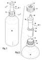
- FIG. 1is a perspective view of a dispenser according to a first preferred embodiment of the present invention illustrating the dispenser mounted on a bottle adapted to contain a consumable beverage;
- FIG. 2is an exploded view of the dispenser of FIG. 1 illustrating a tubular sleeve that is slidably positionable over the dispenser to secure a dispenser lip to an upper edge of an outer surface of the bottle that defines a bottle mouth therein;
- FIG. 3is a cross-sectional view of the dispenser of FIG. 1 as taken along the line 3 - 3 of FIG. 1 and illustrates a plunger in a first plunger position with a plunger end extending outwardly from the first dispenser end of the dispenser body;
- FIG. 4is a cross-sectional view of the dispenser of FIG. 3 as taken along the line 4 - 4 of FIG. 3 and illustrates at least one guide projection that extends outwardly from the plunger and slidably abuts an inner chamber surface to maintain the proper alignment of the plunger within the chamber;
- FIG. 5is a cross-sectional view of the dispenser of FIG. 1 , similar to that of FIG. 3 , and illustrates the plunger in a second plunger position such that the plunger has penetrated a portion of the dispenser body to allow the flavoring component to mix with the consumable beverage and illustrates the cap in a first cap position such that the plunger end cooperates with the cap to seal the cap opening and to prevent the flow of consumable beverage or flavoring component through the dispenser;
- FIG. 6is a cross-sectional view of the dispenser of FIG. 1 similar to that of FIG. 3 , illustrating the cap in the second cap position for drinking therefrom;
- FIG. 7is a perspective view of a dispenser according to a second preferred embodiment of the present invention prior to insertion in the bottle;
- FIG. 8is cross-sectional view of the dispenser of FIG. 7 mounted to the bottle and illustrates the tubular sleeve being integrally formed with the dispenser body such that tubular sleeve is disposed over and spaced from a portion of the dispenser body to create a perimeter groove around the dispenser body that is adapted to receive a portion of the bottle and that defines a bottle opening;
- FIG. 9is cross-sectional view of the dispenser of FIG. 7 , similar to that of FIG. 8 , and illustrates the plunger in the second plunger position and the cap in the first cap position;
- FIG. 10is a cross-sectional view of the dispenser of FIG. 7 with the plunger in the second plunger position and the cap in the first cap position;
- FIG. 11is a perspective view of a dispenser according to a third preferred embodiment of the present invention secured to the bottle;
- FIG. 12is an exploded view of the dispenser of FIG. 11 ;
- FIG. 13is a cross-sectional view of the dispenser of FIG. 11 as taken along the line 13 - 13 of FIG. 11 and illustrates a removable member maintaining the cap in the second cap position with the plunger in a first plunger position in which the plunger generally extends between an inner cap surface and the second dispenser end;
- FIG. 14is a cross-sectional view of the dispenser of FIG. 11 , similar to that of FIG. 13 , and illustrates the dispenser with the removable member detached such that the cap can be moved into the first cap position to drive the plunger into a second plunger position in which the plunger penetrates the dispenser body to form a passageway between the chamber and the interior of the bottle;
- FIG. 15is a perspective view of a dispenser according to a fourth preferred embodiment of the present invention illustrating the dispenser prior to being to secured to the bottle;
- FIG. 16is a cross-sectional view of the dispenser of FIG. 15 secured to the bottle and illustrates the cap in the first cap position with the plunger in the second plunger position;
- FIG. 17is a perspective view of a dispenser according to a fifth preferred embodiment of the present invention prior to being secured to the bottle;
- FIG. 18is a cross-sectional view of the dispenser of FIG. 17 secured to the bottle and illustrates the plunger in a first plunger position
- FIG. 19is a cross-sectional view of the dispenser of FIG. 17 , similar to that of FIG. 18 and illustrates the plunger after the dispenser body has driven the plunger to penetrate a portion of the dispenser body during the securing of the dispenser body to the bottle;
- FIG. 20is a perspective view of a dispenser according to a sixth preferred embodiment of the present invention prior to securing the dispenser to the bottle;
- FIG. 21is a cross-sectional view of the dispenser of FIG. 20 and illustrates the dispenser just prior to the engagement of the dispenser to the bottle;
- FIG. 22illustrates the dispenser of FIG. 20 with the plunger in the second position after being driven by a portion of the dispenser body during the securing the dispenser body to the bottle;
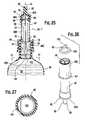
- FIG. 23is a perspective view of a dispenser according to a seventh preferred embodiment of the present invention illustrating the dispenser mounted on the bottle which is adapted to contain a consumable beverage;
- FIG. 24is an exploded view of the dispenser of FIG. 23 which is preferably configured to be reusable;
- the tubular sleevemay be slidably positionable over the dispenser to secure the dispenser lip to an upper edge of an outer surface of the bottle that defines a bottle mouth therein;
- FIG. 25is a cross-sectional view of the dispenser of FIG. 23 as taken along the line 25 - 25 of FIG. 23 and illustrates the recloseable cap in the closed position on the bottom of the dispenser with the plunger in a first plunger position;
- FIG. 26is a partially exploded view of the dispenser of FIG. 23 showing the recloseable cap separate from the dispenser and having a panel that is in an open position to allow the contents of the dispenser to be released therefrom;
- the recloseable capcan be integrally formed with the dispenser bottom or any other suitable mechanism for making the dispenser reusable can be used without departing from the scope of the present invention;
- FIG. 27is a cross-sectional view of the dispenser of FIG. 25 as taken along the line 27 - 27 in FIG. 25 and illustrates the panel in the closed position;
- FIG. 28is a cross-sectional view similar to that of FIG. 25 that shows the dispenser of FIG. 23 with the plunger in the second plunger position with the panel abutted, dislodged, penetrated by the plunger, or moved;
- the panelis in the open position which allows the flavoring component of the dispenser to mix with the consumable beverage;
- the capis in the first cap position which generally prevents drinking from the bottle;
- FIG. 29is a cross-sectional view similar to that of FIG. 28 of the dispenser of FIG. 23 showing the cap in the second cap position for drinking therefrom;
- FIG. 30is a cross-sectional view of the dispenser of FIG. 28 taken along the line 30 - 30 of FIG. 28 and illustrates the panel in the open position;
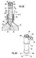
- FIG. 31is a perspective view of a dispenser according to an eighth preferred embodiment of the present invention prior to insertion in the bottle;
- FIG. 32is cross-sectional view of the dispenser of FIG. 31 mounted to the bottle and illustrates the dispenser having a recloseable lid positioned on the bottom thereof to allow the flavoring component to be dispensed; the lid can preferably be reattached after the dispenser has been refilled after use;
- FIG. 33is cross-sectional view of the dispenser of FIG. 32 , similar to that of FIG. 28 , and illustrates the plunger in the second plunger position and the cap in the first cap position;
- the recloseable lidwhich forms part of the dispenser body, is in the open position after penetration of the dispenser body by the plunger;
- FIG. 34is a perspective view of the dispenser of FIG. 33 with the lid in the open position;
- FIG. 35is a perspective view of a dispenser according to a ninth preferred embodiment of the present invention secured to the bottle;
- the dispenseris preferably inserted into the tubular sleeve after the tubular sleeve has been attached to the bottle; This allows the dispenser to be slid in and out of the bottle with minimum manipulation to facilitate swapping dispensers during use or to facilitate the selection of an individual dispenser prior to consumption of the bottle contents;
- FIG. 36is a cross-sectional view of the dispenser of FIG. 35 and illustrates the connection between the dispenser and a portion of the tubular sleeve based on a preferred double lip that extends around the dispenser;
- the connectioncan be a twist lock, detent, snap fit, tongue and groove, friction fit, or any other suitable connection without departing from the scope of the present invention.
- FIG. 37is a cross-sectional view of the dispenser of FIG. 35 , similar to that of FIG. 36 , and illustrates the dispenser with the plunger in a second plunger position in which the plunger penetrates the dispenser body to form a passageway between the chamber and the interior of the bottle; The dispenser's recloseable lid is illustrated in the open position;
- FIG. 38is a perspective view of the dispenser with the recloseable lid in the open position
- FIG. 39illustrates a dispenser of FIG. 35 and a broken away portion of the tubular sleeve; the dispenser has a post thereon for engaging a groove along an inner surface of the portion of the sleeve; The post and groove combine to form a twist lock connection;
- FIG. 40illustrates the dispenser of FIG. 35 and a broken away portion of the tubular sleeve; the dispenser has a post thereon for engaging a generally spiral slot along an inner surface of the portion of the sleeve;
- FIG. 41is a partial cross-sectional view of the dispenser engaged with the tubular sleeve;
- the inner portion of the tubular sleevetapers inwardly in a generally conical fashion to provide an interference fit with the dispenser;
- the tubular sleevepreferably includes a gasket along an upper part of the inner portion to facilitate a fluid tight connection.
- flavoring componentas used in the claims and in the corresponding portions of the specification, is defined as meaning “a juice concentrate, a drink mix, a drink powder, a vitamin mix, a protein powder, a liquid containing caffeine, a flavoring element, a coloring element, a dye, a food coloring, or the like.”
- flavoring componentas used in the claims and in the corresponding portions of the specification, is defined as meaning “a juice concentrate, a drink mix, a drink powder, a vitamin mix, a protein powder, a liquid containing caffeine, a flavoring element, a coloring element, a dye, a food coloring, or the like.”
- the words “a” and “one”are defined as including one or more of the referenced item unless specifically stated otherwise. This terminology includes the words above specifically mentioned, derivatives thereof, and words of similar import.
- the dispenser 30 : 1 - 30 : 9is adapted to contain a flavoring component 32 in a chamber 34 within a dispenser body 40 .
- the flavoring component 32is preferably selectively dispensed into a consumable beverage 36 contained in a bottle 38 to which the dispenser 30 : 1 - 30 : 9 is attached.
- dispenser 30 : 1 - 30 : 9 of the present inventionare similar and operate in a generally similar fashion.
- the first preferred dispenser 30 : 1will be described and, thereafter, only the differences between the first preferred dispenser 30 : 1 and the remaining preferred dispensers 30 : 2 - 30 : 9 will be discussed. Accordingly, it is understood that those features discussed in connection with any one of the embodiments of the dispensers 30 : 1 - 30 : 9 will operate generally the same in the remaining embodiments unless otherwise described.
- the various features shown in the drawings and described in the specificationcan be interchanged without departing from the scope of the present invention.
- the dispenser 30 : 1 - 30 : 9is formed of a sturdy, non-reactive, durable, lightweight material, suitable for use with beverages, such as a suitable polymer.
- a sturdy, non-reactive, durable, lightweight materialsuitable for use with beverages, such as a suitable polymer.
- any known material suitable for use with consumable beveragesbe can used without departing from the scope of the present invention.
- one embodiment of the dispenser 30 : 1 of the present inventionis adapted for a person to drink from and is adapted to engage the bottle 38 .
- the dispenser 30 : 1includes the dispenser body 40 that defines the chamber 34 therein.
- the chamber 34is adapted to hold the flavoring component 32 .
- the dispenser body 40is preferably formed in a cylindrical fashion. Referring specifically to FIG. 3 , the dispenser body 40 may have a longitudinal axis 44 .
- the chamber 34preferably has at least first and second chamber sections 46 A, 46 B.
- the first chamber sectionincludes a first dispenser end 42 A.
- the first chamber cross-sectionis preferably greater than a second chamber cross-section, as measured perpendicular to the longitudinal axis 44 . That is, the first chamber section 46 A is preferably located at the top of the chamber 34 with a side that is bounded by an inner surface 48 of a cap 50 .
- the second chamber section 46 Bis preferably located adjacent to the first chamber section 42 A. It is preferred that the first and second chamber sections 46 A, 46 B are cylindrical.
- the chamber 34include a chamber shoulder 52 that is adapted to abut at least one guide projection 54 (further described below) to prevent a plunger 56 (further described below) from being completely withdrawn from the dispenser body 40 .
- the chamber shoulder 52can be formed at an interface between the second chamber section 46 B and a third chamber section 46 C.
- the third chamber section 46 Cpreferably has a third chamber cross-section, as measured perpendicularly to the longitudinal axis 44 , that is greater than the second chamber cross-section.
- the first dispenser end 42 Ais preferably open.
- the first end 42 A of the dispenseris substantially closed by the cap 50 positioned on the first dispenser 42 A. While a particular shape has been described above for the chamber 34 contained in the dispenser body 40 , those of ordinary skill in the art will appreciate from this disclosure that the dimensions and shape of the chamber 34 can be varied without departing from scope of the present invention.
- the dispenser bodyhas a first dispenser end 42 A suitable for drinking therefrom.
- the dispenserhas a second dispenser end 42 B that is adapted to be positioned within the bottle 38 when the dispenser 30 : 1 is engaged with the bottle 38 . While the second end 42 B is generally shown as only slightly protruding past the neck of the bottle 38 , those of ordinary skill in the art will appreciate from this disclosure that the amount of penetration of the second dispenser end 42 B into the bottle 38 can vary without departing from the scope of the present invention.
- the dispenser body 40preferably includes a penetrable section 60 disposed on the second dispenser end 42 B. As best shown in FIG. 2 , the dispenser body 40 also preferably includes an outwardly directed dispenser lip 64 that forms a dispenser shoulder 66 that is adapted to be seated on a bottle surface 68 that defines a bottle opening 70 .
- a tubular sleeve 72is slidably engagable over the dispenser 30 : 1 to secure the dispenser 30 : 1 at least partially in the bottle opening 70 .
- the tubular sleeve 72is preferably threadably engagable with the bottle 38 via the engagement of at least one sleeve thread 76 with at least one bottle thread 74 .
- the tubular sleeve 72can be integrally formed with the dispenser body 40 such that the tubular sleeve is disposed over and spaced from a portion of the dispenser 40 to create a perimeter groove 78 around the dispenser body 40 that is adapted to receive the portion of the bottle surface 68 that defines the bottle opening 70 .
- the plunger 56is slidably disposed at least partially within the dispenser body 40 for movement from a first plunger position (shown in FIG. 3 ), in which a plunger end 58 extends outwardly from the first dispenser end 42 A of the dispenser body 40 , to a second a plunger position (shown in FIGS. 5 and 6 ), in which the plunger 56 penetrates a portion 60 of the dispenser body 40 to create a passageway 62 .
- the passageway 62is adapted to allow the flavoring component 32 from the chamber 34 to mix with the consumable beverage 36 in the bottle 38 .
- the plunger end 58forms a button 80 that, while the plunger 56 is in the first plunger position, is adapted for a person to depress (i.e., to move inwardly) to allow the flavoring component 32 to mix with the consumable beverage 36 .
- the button 80can have any shape depending upon the desired cap opening 82 (that preferable correlation is further described below).
- the plunger 56preferably includes at least one gasket 84 extending outwardly therefrom.
- the at least one gasket 84preferably forms a chamber seal 86 (shown in FIG. 3 ) between the plunger 56 and an inner chamber surface 48 along the first chamber section 46 A when the plunger 56 is in the first plunger position (as shown in FIG. 3 ).
- the chamber seal 86is adapted to prevent the flavoring component 32 from being dispensed through the cap 50 . This simplifies transportation and handling of the dispenser 30 : 1 prior to use.
- the at least one gasket 84is preferably spaced from the inner chamber surface along the second chamber section 46 B when the plunger 56 is in the second position (shown in FIGS. 5 and 6 ) to form a chamber passageway 88 .
- the chamber passageway 88is adapted to allow the flavoring component 32 and/or the consumable beverage 36 to flow through the chamber 34 toward the cap 50 .
- the chamber passageway 88preferably extends generally about the perimeter of the at least one gasket 84 due to the increased cross-sectional area of the second chamber section 46 B relative to the first chamber section 46 A. It is preferred that the plunger 56 include at least one guide projection 54 that extends outwardly therefrom and slidably abuts the inner chamber surface 48 .
- the guide projection 54comprise four fins 90 that are spaced generally equidistantly about the plunger 56 .
- the guide projection 54can be used provided that the flavoring component 32 and/or the consumable beverage 36 can pass by the guide projection(s) 54 .
- the amount of force necessary to move the plunger 56 from the first plunger position to the second plunger positioncan be customized to customer taste.
- the cap 50is slidably positioned on the first dispenser end 42 A of the dispenser body and defines a cap opening 82 adapted to allow a person to drink the consumable beverage 36 therefrom. It is preferable that the cap 50 is slidable upwardly and downwardly on the dispenser 40 .
- the capis moveable between a first cap position (shown in FIG. 5 ), in which the cap opening 82 is proximate to the first dispenser end 42 A of the dispenser body 40 , and a second cap position (shown in FIG. 6 ) in which the cap opening 82 is spaced further from the first dispenser end 42 A than when the cap 50 is in the first cap position.
- the plunger end 58cooperates with the cap 50 to seal the cap opening 82 so that the dispenser 30 : 1 is adapted to prevent the consumable beverage 36 from leaving the bottle 38 .
- the cap opening 82can have any shape and it is preferable that the button 80 formed by the plunger end 58 of the plunger 56 is complimentarily shaped.
- the second preferred embodiment of the dispenser 30 : 2is similar in design and operation to the first preferred dispenser 30 : 1 , except for the tubular sleeve 72 is integrally formed with the dispenser body 40 .
- a third preferred embodiment of the dispenser 30 : 3preferably includes a removable member 92 that is disposed about the dispenser body 40 and is adapted to prevent the cap 50 from sliding thereon.
- the removable member 92is disposed beneath a bottom edge of the cap 50 and above an upper dispenser body shoulder 94 .
- the cap 50is slidable from a second cap position (shown in FIG. 13 ), in which the inner cap surface 48 is spaced from the first dispenser end 42 A, to a first cap position (as shown in FIG. 14 ), in which the inner cap surface 48 is at least in close proximity to the first dispenser end 42 A.
- the term “at least in close proximity”means “preferably abutting contact therebetween or within a reasonable tolerance, such as between approximately two (2) and four (4) millimeters or the like.”
- the plunger 56is slidably disposed at least partially within the dispenser body for movement from a first plunger position (shown in FIG. 13 ), in which the plunger extends generally between the inner cap surface 48 and the second dispenser end 42 B, to a second plunger position (shown in FIG. 14 ), in which the plunger 56 penetrates a portion 60 of the dispenser body 40 to create a passageway 62 .
- the cap 50can be moved into the first cap position to drive the plunger 56 from the first plunger position to the second plunger position to selectively disperse the flavoring component 32 into the bottle 38 .
- the fourth preferred dispenser 30 : 4is substantially similar to third preferred dispenser 30 : 3 , except that the tubular sleeve 72 is integrally formed with the dispenser body 40 .
- the dispensers 30 : 1 - 30 : 6can be sonically welded, integrally formed with a heat weld, hot wire welded, or adhesively fixed to the bottle 38 without departing from the scope of the present invention.
- a fifth preferred embodiment of the dispenser 30 : 5 of the present inventionincludes a dispenser body having a consumable beverage passageway 96 extending between the first dispenser body end 42 A and a portion of a dispenser outer surface 98 and is adapted to be located within the bottle 38 when the dispenser 30 : 5 is engaged with the bottle 38 .
- the chamber 34it is preferred, but not necessary, that the chamber 34 not be in fluid communication with the first dispenser end 42 A except for by following a liquid path through the consumable beverage 36 in the bottle and into the dispenser 40 via the portion of the dispenser outer surface 98 that opens to the consumable beverage passageway 96 .
- the plunger 56is preferably disposed within the dispenser body 40 such that when the dispenser 30 : 5 is secured to bottle 38 , the dispenser body 40 drives the plunger 56 to penetrate a portion of the dispenser body 60 to create a passageway 62 and thus, encouraging any flavoring component 32 that is consumed by a person to flow through the bottle 38 and back into the dispenser body 40 via the consumable beverage passageway 96 .
- the plunger 56is out of contact with the penetrable section 60 when the tubular sleeve 72 is beginning to engage the bottle 38 .
- the upper half of the dispenser body 40drives the plunger 56 downwardly until the tubular sleeve 36 is engaged with the bottle 38 sufficiently to force the plunger 56 downwardly through the penetratable section 60 of the dispenser body 40 .
- the penetrable portion 60 of any of the dispensers 30 : 1 - 30 : 6can be formed by a foil, a partially perforated polymer section, or the like without departing from the scope of the present invention.
- one embodiment of the present inventionoperates as follows.
- the second dispenser end 42 Bis inserted into the bottle opening 70 such that the dispenser lip 64 abuts the bottle surface 68 .
- the tubular sleeve 72is slid over the top of the dispenser body 40 and threadably secured to the bottle 38 .
- the tubular sleeve 72clamps the dispenser lip 64 between an upper, annular ring, portion of the tubular sleeve 72 and the bottle surface 68 to secure the dispenser 30 : 1 thereto.
- a userdepresses button 80 to drive the plunger 56 downwardly through the penetrable section 60 to create a passageway 62 .
- any flavoring component 32 within the chamber 34 of the dispenser 30 : 1is then allowed to pass through the passageway 62 and mix with the consumable beverage 36 .
- the consumable beverage 36 and/or the flavoring component 32are preferably prevented from being ejected from the bottle via the dispenser 30 ; 1 .
- the userpulls the cap 50 upwardly into the second cap position as shown in FIG. 6 .
- the dispenser 30 : 7is preferably configured to be reusable.
- the bottom of the dispensermay include a recloseable cap 100 with a panel 102 therein that is moveable between an open position (shown in FIGS. 28-30 ) and a closed position (shown in FIGS. 24 , 25 , and 27 ).
- the tubular sleeve 72may be slidably positionable over the dispenser 30 : 7 to secure the dispenser lip 64 to an upper edge 68 of the bottle opening 70 .
- the panel 102is preferably connected to the recloseable cap 100 via a living hinge.
- a section of the panel 102preferably forms a bevel 122 that is configured to engage a protuberance 120 on the recloseable cap 100 to allow the panel to be secured in the closed position. While a preferred construction for a reusable dispenser 30 : 7 is shown, those of ordinary skill in the art will appreciate from this disclosure that any suitable recloseable/resealable structure or mechanism can be used on the lower end of the dispenser 30 : 7 without departing from the scope of the present invention.
- the recloseable cap 100can be integrally formed with the dispenser bottom or can be sonically welded thereto or secured using any suitable method without departing from the scope of the present invention. Furthermore, any other suitable mechanism for making the dispenser 30 : 7 reusable can be used without departing from the scope of the present invention.
- FIGS. 31-34illustrate an eighth preferred embodiment of the dispenser 30 : 8 .
- the dispenserusers a recloseable lid 104 that is connected via a strap 106 .
- the lid 104can form the lower end of the dispenser body 40 until it is penetrated by the plunger 56 .
- FIG. 33illustrates the recloseable lid 104 in the open position after penetration of the dispenser body by the plunger 56 .
- FIGS. 35-41illustrate a ninth preferred embodiment of the dispenser 30 : 9 .
- the dispenseris preferably inserted into the tubular sleeve 72 after the tubular sleeve 72 has been attached to the bottle 38 .
- Thisallows the dispenser 30 : 9 to be slid in and out of the bottle 38 with minimum manipulation to facilitate swapping dispensers during use or to facilitate the selection of an individual dispenser 30 : 9 prior to consumption of the bottle contents. It further allows the dispenser to be a generally cylindrical piece with a minimum of protruding components to facilitate shipping and handling by children.
- the dispenser 30 : 9is preferably inserted into a portion 108 of the tubular sleeve 72 that may extend into the opening of the bottle. Referring to FIG.
- connectionbetween the dispenser 30 : 9 and a portion 108 of the tubular sleeve 72 based on a preferred double lip 64 that extends around the dispenser 30 : 9 .
- the connectioncan be a twist lock (shown in FIG. 39 ), detent, snap fit, tongue and groove (shown in FIG. 40 ), friction fit (shown in FIG. 41 ), or any other suitable connection without departing from the scope of the present invention.
- FIG. 39illustrates the dispenser 30 : 9 and a broken away portion of the tubular sleeve 72 .
- the dispenser 30 : 9can have a post 112 thereon for engaging a groove 110 along an inner surface of the portion 108 of the sleeve 72 .
- the post 112 and groove 110preferably combine to form a twist lock connection.
- the dispenser 30 : 9may use the post 112 for engaging a generally spiral slot 114 along an inner surface of the portion 108 of the sleeve 72 to form a tongue and groove connection.
- the dispenser 30 : 9may be engaged with the tubular sleeve 72 via the inner portion 108 .
- the inner portion 108 of the tubular sleevepreferably tapers 118 inwardly in a generally conical fashion to provide an interference fit with the dispenser.
- the interference fitmay be made more reliable by selecting materials that have high frictional coefficient therebetween.
- the tubular sleeve 72preferably includes a gasket 116 along an upper part of the inner portion 108 to facilitate a fluid tight connection. While specific mechanisms for connection the dispenser 30 : 9 to the bottle have been disclosed, any suitable connection may be used without departing from the scope of the present invention.
Landscapes
- Engineering & Computer Science (AREA)
- Mechanical Engineering (AREA)
- Closures For Containers (AREA)
Abstract
Description
Claims (15)
Priority Applications (4)
| Application Number | Priority Date | Filing Date | Title |
|---|---|---|---|
| US11/931,229US8011534B2 (en) | 2003-02-10 | 2007-10-31 | Flavoring component holding dispenser for use with consumable beverages |
| US12/575,994US7909210B2 (en) | 2003-02-10 | 2009-10-08 | Flavoring component holding dispenser for use with consumable beverages |
| US13/224,711US8499971B2 (en) | 2003-02-10 | 2011-09-02 | Flavoring component holding dispenser for use with consumable beverages |
| US13/958,930US20130327788A1 (en) | 2003-02-10 | 2013-08-05 | Flavoring component holding dispenser for use with consumable beverages |
Applications Claiming Priority (3)
| Application Number | Priority Date | Filing Date | Title |
|---|---|---|---|
| US10/361,269US6959839B2 (en) | 2003-02-10 | 2003-02-10 | Flavoring component holding dispenser for use with consumable beverages |
| US11/019,488US7306117B2 (en) | 2003-02-10 | 2004-12-22 | Flavoring component holding dispenser for use with consumable beverages |
| US11/931,229US8011534B2 (en) | 2003-02-10 | 2007-10-31 | Flavoring component holding dispenser for use with consumable beverages |
Related Parent Applications (1)
| Application Number | Title | Priority Date | Filing Date |
|---|---|---|---|
| US11/019,488Continuation-In-PartUS7306117B2 (en) | 2003-02-10 | 2004-12-22 | Flavoring component holding dispenser for use with consumable beverages |
Related Child Applications (2)
| Application Number | Title | Priority Date | Filing Date |
|---|---|---|---|
| US12/575,994DivisionUS7909210B2 (en) | 2003-02-10 | 2009-10-08 | Flavoring component holding dispenser for use with consumable beverages |
| US13/224,711ContinuationUS8499971B2 (en) | 2003-02-10 | 2011-09-02 | Flavoring component holding dispenser for use with consumable beverages |
Publications (2)
| Publication Number | Publication Date |
|---|---|
| US20080116221A1 US20080116221A1 (en) | 2008-05-22 |
| US8011534B2true US8011534B2 (en) | 2011-09-06 |
Family
ID=46329741
Family Applications (4)
| Application Number | Title | Priority Date | Filing Date |
|---|---|---|---|
| US11/931,229Expired - Fee RelatedUS8011534B2 (en) | 2003-02-10 | 2007-10-31 | Flavoring component holding dispenser for use with consumable beverages |
| US12/575,994Expired - Fee RelatedUS7909210B2 (en) | 2003-02-10 | 2009-10-08 | Flavoring component holding dispenser for use with consumable beverages |
| US13/224,711Expired - Fee RelatedUS8499971B2 (en) | 2003-02-10 | 2011-09-02 | Flavoring component holding dispenser for use with consumable beverages |
| US13/958,930AbandonedUS20130327788A1 (en) | 2003-02-10 | 2013-08-05 | Flavoring component holding dispenser for use with consumable beverages |
Family Applications After (3)
| Application Number | Title | Priority Date | Filing Date |
|---|---|---|---|
| US12/575,994Expired - Fee RelatedUS7909210B2 (en) | 2003-02-10 | 2009-10-08 | Flavoring component holding dispenser for use with consumable beverages |
| US13/224,711Expired - Fee RelatedUS8499971B2 (en) | 2003-02-10 | 2011-09-02 | Flavoring component holding dispenser for use with consumable beverages |
| US13/958,930AbandonedUS20130327788A1 (en) | 2003-02-10 | 2013-08-05 | Flavoring component holding dispenser for use with consumable beverages |
Country Status (1)
| Country | Link |
|---|---|
| US (4) | US8011534B2 (en) |
Cited By (3)
| Publication number | Priority date | Publication date | Assignee | Title |
|---|---|---|---|---|
| US20100163509A1 (en)* | 2008-12-17 | 2010-07-01 | Mauro Andres Canziani Hoffa | Hermetic closing system, additive dispenser, for containers and/or bottles |
| US8640865B2 (en)* | 2012-05-01 | 2014-02-04 | William Smart | Cap for storing materials separate from a body of liquid and facilitating subsequent mixing of the materials and the liquid |
| US9745115B2 (en) | 2014-02-10 | 2017-08-29 | Joshua Hall | Multi-compartment, portable beverage container |
Families Citing this family (55)
| Publication number | Priority date | Publication date | Assignee | Title |
|---|---|---|---|---|
| US8960424B1 (en)* | 2011-05-27 | 2015-02-24 | Michael R. Anderson | Dispensing capsule with snap in activation chamber |
| US8011534B2 (en) | 2003-02-10 | 2011-09-06 | Cool Gear International, Llc | Flavoring component holding dispenser for use with consumable beverages |
| WO2006035558A1 (en) | 2004-09-29 | 2006-04-06 | Yoshino Kogyosyo Co., Ltd. | Mixing vessel for two-part fluid or the like |
| JP2009509885A (en)* | 2005-10-07 | 2009-03-12 | アマン,レイナー | Closing device |
| CN101730651A (en)* | 2007-04-05 | 2010-06-09 | 弗雷德里克·M·库里 | dispenser |
| CA2721419C (en)* | 2008-04-17 | 2016-05-17 | From The Earth Naturally Ltd. | Dispensing cap for beverage container |
| US9211984B2 (en)* | 2008-04-17 | 2015-12-15 | From The Earth Naturally Ltd. | Dispensing cap for beverage container |
| US20120199503A1 (en)* | 2008-04-17 | 2012-08-09 | Anita Dyrbye | Dispensing cap for beverage container |
| KR100971860B1 (en) | 2008-06-16 | 2010-07-22 | 이우정 | Cosmetic containers |
| FR2938243B1 (en)* | 2008-11-12 | 2013-08-23 | Soc D Thermoformage Et D Injection Des Plastics | DEVICE FOR PRESERVING AND RELEASING A PRODUCT CONTAINED IN A RESERVOIR COMPRISING A BREAKABLE WALL |
| US20100186848A1 (en)* | 2008-12-04 | 2010-07-29 | Moorad Thomas S | Dispenser and method |
| US20110155760A1 (en)* | 2009-12-31 | 2011-06-30 | Christina Wulfson | One handed article dispenser |
| WO2012031120A1 (en) | 2010-09-02 | 2012-03-08 | Kraft Foods Global Brands Llc | Containers and methods for mixing and dispensing beverage concentrates |
| IT1402348B1 (en)* | 2010-09-17 | 2013-08-30 | Biofarma S P A | CHISURA FOR A BOTTLE AND BOTTLE INCLUDING SUCH CLOSING DEVICE |
| US20120234789A1 (en)* | 2010-11-24 | 2012-09-20 | Cool Gear International, Llc | Caps and containers |
| AR084271A1 (en) | 2010-12-14 | 2013-05-02 | Kraft Foods Global Brands Llc | CONTAINERS AND METHODS TO ISOLATE LIQUIDS BEFORE DISPENSING THEM |
| BR112013019530A2 (en)* | 2011-02-01 | 2018-06-19 | Granite State Product Dev Llc | dispensing cap for a container. |
| US10065775B2 (en) | 2011-02-01 | 2018-09-04 | Granite State Product Development LLC | Dispensing cap for a container |
| RU2563781C2 (en)* | 2011-04-05 | 2015-09-20 | УАЙТ ЭлЭлСи | Lid with container for additive and respective package |
| US9242772B1 (en) | 2011-05-27 | 2016-01-26 | Michael R. Anderson | Drink-through dispensing capsule with snap in activation chamber |
| US8857665B2 (en) | 2011-11-15 | 2014-10-14 | John H. Owoc | Beverage container with secondary internal dispensing chamber |
| TWM431147U (en)* | 2011-11-29 | 2012-06-11 | Lie-Shi Wu | Compatible bottle cap |
| US20130139703A1 (en)* | 2011-12-05 | 2013-06-06 | Harold Walter Hogarth | Apparatus and Methods for Providing Additives To Beverages |
| WO2014026852A1 (en)* | 2012-08-12 | 2014-02-20 | Bevaswiss Ag | Closure which can be filled in an oxygen-tight manner and has a pushbutton for triggering purposes |
| ITTO20121006A1 (en)* | 2012-11-20 | 2014-05-21 | Inge Spa | DEVICE FOR THE ERMETIC CONSERVATION OF A SUBSTANCE TO BE MIXED WITH ANOTHER CONTENT IN A CONTAINER. |
| RU2753016C2 (en) | 2012-12-28 | 2021-08-11 | Крафт Фудс Груп Брэндс Ллк | Containers and methods for isolating liquids before dosing |
| US9795242B2 (en) | 2013-02-14 | 2017-10-24 | Cirkul, Inc. | Additive delivery systems and containers |
| US9771194B1 (en)* | 2013-02-28 | 2017-09-26 | Zing Anything Llc | Metered, blending portable beverage container |
| US9359183B2 (en) | 2013-03-14 | 2016-06-07 | Carlon Holdings Llc | Flavored pouring dispenser |
| AU2014243136A1 (en)* | 2013-03-25 | 2015-10-29 | ViCap Systems Europe Asia AG | Closure having a mandrel for a container |
| US20150016208A1 (en)* | 2013-07-15 | 2015-01-15 | Solutions Biomed, Llc | Multi-chamber container for storing and mixing liquids |
| US9162804B2 (en)* | 2013-11-25 | 2015-10-20 | Ezra Hamway | Dispensing cap for attaching to a container |
| JP6326360B2 (en)* | 2014-08-29 | 2018-05-16 | 株式会社吉野工業所 | Refill container |
| WO2016081925A1 (en) | 2014-11-21 | 2016-05-26 | Samsara Bottle System, Inc. | Adjustable additive cartridge systems |
| US10888826B2 (en) | 2014-11-21 | 2021-01-12 | Cirkul, Inc. | Adjustable additive cartridge systems and methods |
| US10464714B2 (en)* | 2014-12-29 | 2019-11-05 | Mauro Andres Canziani Hoffa | Closing assembly for a container, such as bottles and/or flasks, removable cartridges, closing device, and method |
| US10252836B2 (en) | 2015-10-08 | 2019-04-09 | Stephen Frank Charles Geldard | Applicator apparatus, mouth fill devices, collapsible containers and methods |
| US10885562B2 (en)* | 2016-10-18 | 2021-01-05 | Autoalert, Llc | Visual discovery tool for automotive manufacturers with network encryption, data conditioning, and prediction engine |
| US10112752B2 (en) | 2017-01-02 | 2018-10-30 | Toddy Tech, LLC | Tumbler lid with reservoir and repetitive measuring and disbursement mechanism |
| US10421590B2 (en) | 2017-01-02 | 2019-09-24 | Toddy Tech, LLC | Tumbler lid with reservoir and repetitive measuring and disbursement mechanism |
| PL236612B1 (en)* | 2017-11-13 | 2021-02-08 | Krajewski Dariusz Jerzy | Screw cap with the feeder for sachets, preferably for the liquid food products |
| EP3887060A1 (en)* | 2018-11-26 | 2021-10-06 | Dispensing Technologies B.V. | System and method for dispensing a mixture of a liquid and an additive and cartridge for use therein |
| KR102252534B1 (en)* | 2018-12-14 | 2021-05-14 | (주)아모레퍼시픽 | Main container for mixing cosmetic and sub container for mixing cosmetic and cosmetic including same |
| US10548421B1 (en)* | 2019-02-17 | 2020-02-04 | Manus Lositisuk | Multi-compartment beverage container |
| GB2585237A (en)* | 2019-07-05 | 2021-01-06 | Medcap Ltd | Container closure for container |
| US10935406B1 (en)* | 2019-08-16 | 2021-03-02 | Toddy Tech, LLC | Beverage container lid with reservoir and repetitive measuring and disbursement mechanism |
| GB2595478A (en) | 2020-05-27 | 2021-12-01 | Medcap Ltd | Dispenser for selectively delivering a substance in a container |
| US11572226B2 (en)* | 2020-08-19 | 2023-02-07 | Idispense, Llc | Concentrate cartridge with membrane |
| US11840383B2 (en) | 2020-10-23 | 2023-12-12 | Russ Lynn Peterson | Edible material dispensing tab for beverage |
| US12194423B2 (en) | 2022-09-30 | 2025-01-14 | Toddy Tech, LLC | Beverage container lid and beverage container using same |
| USD1088737S1 (en) | 2022-12-08 | 2025-08-19 | Cool Gear International, Llc | Liquid container |
| US12402557B2 (en)* | 2022-12-22 | 2025-09-02 | Meristem Crop Performance Group, LLC | Method and device for delivering biological material to liquid medium |
| USD1071670S1 (en) | 2023-01-09 | 2025-04-22 | Igloo Products Corp. | Jug with lid |
| USD1073411S1 (en) | 2023-03-07 | 2025-05-06 | Igloo Products Corp. | Container |
| CN220555457U (en)* | 2023-05-06 | 2024-03-05 | 科尔曼公司 | reusable bottle |
Citations (51)
| Publication number | Priority date | Publication date | Assignee | Title |
|---|---|---|---|---|
| US3156369A (en) | 1962-09-19 | 1964-11-10 | Ethicon Inc | Bicameral container |
| US3651990A (en)* | 1969-10-23 | 1972-03-28 | Edward J Cernei | Container for keeping liquids in separate condition and commingling and dispensing the same |
| US3655096A (en) | 1969-10-22 | 1972-04-11 | Pillsbury Co | Container for diluting and dispensing material |
| US3966089A (en) | 1975-04-25 | 1976-06-29 | Colgate-Palmolive Company | Diluting and dispensing container |
| US4757916A (en) | 1986-09-12 | 1988-07-19 | L'oreal | Unit allowing two products to be stored separately and to be simultaneously dispensed after they have been brought into contact |
| US4785974A (en) | 1985-08-26 | 1988-11-22 | The Coca-Cola Company | System for serving a pre-mix beverage or making and serving a post-mix beverage in the zero gravity conditions of outer space |
| US4950083A (en) | 1988-08-03 | 1990-08-21 | Eparco | Packaging for a liquid composition which is ready for use, produced from a concentrated liquid composition, and method for its implementation |
| US5000314A (en) | 1989-01-23 | 1991-03-19 | Bristol-Myers Company | Unit dose package |
| US5071034A (en) | 1988-12-05 | 1991-12-10 | Jerome Corbiere | Distributing device for liquid preparations |
| US5125534A (en) | 1991-01-14 | 1992-06-30 | Rose Barry L | Beverage flavoring and dispensing apparatus and method of construction |
| US5246142A (en) | 1991-09-26 | 1993-09-21 | Dipalma Elio | Device for storing two products separately and subsequently mixing them |
| US5325996A (en) | 1993-04-07 | 1994-07-05 | Gondal Pty. Ltd. | Beverage vessel with flavoring concentrate dispenser |
| US5328063A (en) | 1993-06-10 | 1994-07-12 | Creative Packaging Corp. | Venting closure cap |
| US5373937A (en) | 1993-07-16 | 1994-12-20 | Goldwell Ag | Two-compartment container |
| US5419445A (en) | 1994-06-24 | 1995-05-30 | Kaesemeyer; David M. | Container for storing, mixing and dispensing |
| US5421483A (en) | 1992-12-09 | 1995-06-06 | Parise; Bernardino | Container for substances concentrated in the form of powder or a liquid to be placed in solution within a receptacle at the time of use |
| US5474209A (en) | 1992-07-02 | 1995-12-12 | Laboratorios Cusi, S.A. | Pharmaceutical product container with two separate substances and a mixing device and dosed dispensation |
| US5543528A (en) | 1992-03-23 | 1996-08-06 | Sanofi | Imidazolines |
| US5669533A (en) | 1995-08-01 | 1997-09-23 | Creative Products, Inc. | Resealable fluid dispenser cap assembly |
| US5772017A (en) | 1996-10-25 | 1998-06-30 | Kang; Heung Sun | Beverage mixing dispenser device |
| US5836479A (en) | 1994-07-25 | 1998-11-17 | Sprayex L.L.C. | Rechargeable containers and dispensers |
| US5860569A (en) | 1996-06-13 | 1999-01-19 | Carnaudmetalbox Sante-Beaute | Product-dispensing container |
| US5871122A (en) | 1994-07-25 | 1999-02-16 | Sprayex L.L.C. | Rechargeable dispensers |
| US5875888A (en) | 1996-08-02 | 1999-03-02 | L'oreal | Device for separately storing two components, for mixing them, and for dispensing the mixture |
| US5875889A (en) | 1996-08-02 | 1999-03-02 | L'oreal | Device for separately packaging two components, for mixing them together and for dispensing the resulting mixture |
| US5890624A (en) | 1994-07-25 | 1999-04-06 | Sprayex L.L.C. | Rechargeable dispensers |
| US5927549A (en) | 1998-03-20 | 1999-07-27 | Aptargroup, Inc. | Dispensing structure with frangible membrane for separating two products |
| US5947332A (en) | 1994-07-25 | 1999-09-07 | Sprayex, Inc. | Rechargeable dispensers |
| US5950819A (en) | 1998-05-08 | 1999-09-14 | Sellars; Andy | Storage, admixing, and dispensing system |
| US5984141A (en) | 1998-05-20 | 1999-11-16 | Gibler; Gregory A. | Beverage storage and mixing device |
| US6041969A (en) | 1997-06-10 | 2000-03-28 | Parise; Bernardino | Container for concentrated powder or liquid substances to be put in solution within an enclosure at the time of use |
| US6050452A (en) | 1997-09-10 | 2000-04-18 | Novembal | Push-pull closure with reinforced tamper-proofing |
| US6092649A (en) | 1998-10-22 | 2000-07-25 | Sermed Industries Inc. | Cartridge for holding a first and second fluid |
| US6116445A (en) | 1997-09-09 | 2000-09-12 | Kabushikikaisha Fancl | Sealing cap for containers |
| US6123230A (en) | 1998-05-21 | 2000-09-26 | Sprayex, Inc. | Probe for rechargeable dispensers |
| US6155459A (en) | 1997-12-15 | 2000-12-05 | Diversey Lever, Inc. | Spray dispenser |
| US6165523A (en) | 1999-04-26 | 2000-12-26 | Story; Douglas | Injector bottle cap assembly |
| US6182865B1 (en) | 1997-03-27 | 2001-02-06 | Deversey Lever, Inc. | Device for storing a liquid co-operable with a spray dispenser, and spray dispenser comprising said device |
| US6224922B1 (en) | 1999-12-16 | 2001-05-01 | Mark J. Fonte | Drink colorizer |
| US6250511B1 (en) | 1999-11-05 | 2001-06-26 | Albert R. Kelly | Recharge insert for cleaning, sanitizing or disinfectant fluid spray system |
| US6269979B1 (en) | 1999-10-05 | 2001-08-07 | Charles Dumont | Multi-compartmented mixing dispenser |
| US6290100B1 (en) | 2000-06-30 | 2001-09-18 | Canberra Corporation | Concentrate cartridge for a diluting and dispensing container |
| US6305576B1 (en) | 2000-01-19 | 2001-10-23 | Nalge Nunc International Corporation | Cartridge for aseptically holding and dispensing a fluid material, and a container and method for aseptically holding and mixing the fluid material |
| US6367622B1 (en)* | 2000-08-01 | 2002-04-09 | Lily Hsu | Container with separate storage spaces |
| US6372270B1 (en) | 1999-05-26 | 2002-04-16 | Sean P. Denny | Drink mix apparatus for making personal quantities of beverage |
| US6412526B2 (en) | 1999-05-28 | 2002-07-02 | James A. Castillo | Device for maintaining separate ingredients in liquid food products |
| US6672817B2 (en) | 2000-05-16 | 2004-01-06 | Sean P. Denny | Beverage preparation and dispensing container |
| US6772910B1 (en) | 1999-11-17 | 2004-08-10 | Fredrick Michael Coory | Piercing cap for a container |
| US20040155061A1 (en) | 2003-02-10 | 2004-08-12 | Donna Roth | Flavoring component holding dispenser for use with consumable beverages |
| US7562782B2 (en)* | 2004-10-08 | 2009-07-21 | Nippon Kouatsu Electric Co., Ltd. | Cap structure for beverage container |
| US7909210B2 (en) | 2003-02-10 | 2011-03-22 | Cool Gear International, Llc | Flavoring component holding dispenser for use with consumable beverages |
Family Cites Families (9)
| Publication number | Priority date | Publication date | Assignee | Title |
|---|---|---|---|---|
| US219642A (en) | 1879-09-16 | Improvement in jewel-caskets | ||
| US100412A (en) | 1870-03-01 | Improvement in churns | ||
| US5975360A (en)* | 1991-05-20 | 1999-11-02 | Ophardt; Heiner | Capped piston pump |
| IT1264668B1 (en) | 1993-07-05 | 1996-10-04 | Inge Spa | BOTTLE FOR STORAGE IN SEPARATE CONDITION OF SUBSTANCES TO BE MIXED BEFORE DISPENSING |
| FR2729920B1 (en)* | 1995-02-01 | 1997-06-06 | Kerplas Snc | BOTTLE BODY AND BOTTLE FOR DISPENSING A PRODUCT |
| AUPP408498A0 (en) | 1998-06-12 | 1998-07-02 | Clarkson, Aron Joseph | Improvements in closures for containers |
| IT1316941B1 (en)* | 2000-10-25 | 2003-05-13 | Lameplast Spa | BOTTLE FOR BICOMPENENT ESTEMPORARY PRODUCTS. |
| EP1663807A4 (en) | 2003-09-09 | 2009-01-21 | Aron Joseph Clarkson | Dispensing closure |
| PL1737743T3 (en) | 2005-03-23 | 2009-10-30 | Wilhelm Rene | 'push-pull' type closure for a container |
- 2007
- 2007-10-31USUS11/931,229patent/US8011534B2/ennot_activeExpired - Fee Related
- 2009
- 2009-10-08USUS12/575,994patent/US7909210B2/ennot_activeExpired - Fee Related
- 2011
- 2011-09-02USUS13/224,711patent/US8499971B2/ennot_activeExpired - Fee Related
- 2013
- 2013-08-05USUS13/958,930patent/US20130327788A1/ennot_activeAbandoned
Patent Citations (55)
| Publication number | Priority date | Publication date | Assignee | Title |
|---|---|---|---|---|
| US3156369A (en) | 1962-09-19 | 1964-11-10 | Ethicon Inc | Bicameral container |
| US3655096A (en) | 1969-10-22 | 1972-04-11 | Pillsbury Co | Container for diluting and dispensing material |
| US3651990A (en)* | 1969-10-23 | 1972-03-28 | Edward J Cernei | Container for keeping liquids in separate condition and commingling and dispensing the same |
| US3966089A (en) | 1975-04-25 | 1976-06-29 | Colgate-Palmolive Company | Diluting and dispensing container |
| US4785974A (en) | 1985-08-26 | 1988-11-22 | The Coca-Cola Company | System for serving a pre-mix beverage or making and serving a post-mix beverage in the zero gravity conditions of outer space |
| US4757916A (en) | 1986-09-12 | 1988-07-19 | L'oreal | Unit allowing two products to be stored separately and to be simultaneously dispensed after they have been brought into contact |
| US4950083A (en) | 1988-08-03 | 1990-08-21 | Eparco | Packaging for a liquid composition which is ready for use, produced from a concentrated liquid composition, and method for its implementation |
| US5071034A (en) | 1988-12-05 | 1991-12-10 | Jerome Corbiere | Distributing device for liquid preparations |
| US5000314A (en) | 1989-01-23 | 1991-03-19 | Bristol-Myers Company | Unit dose package |
| US5125534A (en) | 1991-01-14 | 1992-06-30 | Rose Barry L | Beverage flavoring and dispensing apparatus and method of construction |
| US5246142A (en) | 1991-09-26 | 1993-09-21 | Dipalma Elio | Device for storing two products separately and subsequently mixing them |
| US5543528A (en) | 1992-03-23 | 1996-08-06 | Sanofi | Imidazolines |
| US5474209A (en) | 1992-07-02 | 1995-12-12 | Laboratorios Cusi, S.A. | Pharmaceutical product container with two separate substances and a mixing device and dosed dispensation |
| US5421483A (en) | 1992-12-09 | 1995-06-06 | Parise; Bernardino | Container for substances concentrated in the form of powder or a liquid to be placed in solution within a receptacle at the time of use |
| US5325996A (en) | 1993-04-07 | 1994-07-05 | Gondal Pty. Ltd. | Beverage vessel with flavoring concentrate dispenser |
| US5328063A (en) | 1993-06-10 | 1994-07-12 | Creative Packaging Corp. | Venting closure cap |
| US5373937A (en) | 1993-07-16 | 1994-12-20 | Goldwell Ag | Two-compartment container |
| US5419445A (en) | 1994-06-24 | 1995-05-30 | Kaesemeyer; David M. | Container for storing, mixing and dispensing |
| US5947332A (en) | 1994-07-25 | 1999-09-07 | Sprayex, Inc. | Rechargeable dispensers |
| US5890624A (en) | 1994-07-25 | 1999-04-06 | Sprayex L.L.C. | Rechargeable dispensers |
| US5836479A (en) | 1994-07-25 | 1998-11-17 | Sprayex L.L.C. | Rechargeable containers and dispensers |
| US5871122A (en) | 1994-07-25 | 1999-02-16 | Sprayex L.L.C. | Rechargeable dispensers |
| US5669533A (en) | 1995-08-01 | 1997-09-23 | Creative Products, Inc. | Resealable fluid dispenser cap assembly |
| US5860569A (en) | 1996-06-13 | 1999-01-19 | Carnaudmetalbox Sante-Beaute | Product-dispensing container |
| US5875888A (en) | 1996-08-02 | 1999-03-02 | L'oreal | Device for separately storing two components, for mixing them, and for dispensing the mixture |
| US5875889A (en) | 1996-08-02 | 1999-03-02 | L'oreal | Device for separately packaging two components, for mixing them together and for dispensing the resulting mixture |
| US5772017A (en) | 1996-10-25 | 1998-06-30 | Kang; Heung Sun | Beverage mixing dispenser device |
| US6182865B1 (en) | 1997-03-27 | 2001-02-06 | Deversey Lever, Inc. | Device for storing a liquid co-operable with a spray dispenser, and spray dispenser comprising said device |
| US6041969A (en) | 1997-06-10 | 2000-03-28 | Parise; Bernardino | Container for concentrated powder or liquid substances to be put in solution within an enclosure at the time of use |
| US6116445A (en) | 1997-09-09 | 2000-09-12 | Kabushikikaisha Fancl | Sealing cap for containers |
| US6050452A (en) | 1997-09-10 | 2000-04-18 | Novembal | Push-pull closure with reinforced tamper-proofing |
| US6155459A (en) | 1997-12-15 | 2000-12-05 | Diversey Lever, Inc. | Spray dispenser |
| US5927549A (en) | 1998-03-20 | 1999-07-27 | Aptargroup, Inc. | Dispensing structure with frangible membrane for separating two products |
| US5950819A (en) | 1998-05-08 | 1999-09-14 | Sellars; Andy | Storage, admixing, and dispensing system |
| US5984141A (en) | 1998-05-20 | 1999-11-16 | Gibler; Gregory A. | Beverage storage and mixing device |
| US6123230A (en) | 1998-05-21 | 2000-09-26 | Sprayex, Inc. | Probe for rechargeable dispensers |
| US6152326A (en) | 1998-05-21 | 2000-11-28 | Sprayex, Inc. | Probe for rechargeable dispensers |
| US6092649A (en) | 1998-10-22 | 2000-07-25 | Sermed Industries Inc. | Cartridge for holding a first and second fluid |
| US6165523A (en) | 1999-04-26 | 2000-12-26 | Story; Douglas | Injector bottle cap assembly |
| US6372270B1 (en) | 1999-05-26 | 2002-04-16 | Sean P. Denny | Drink mix apparatus for making personal quantities of beverage |
| US6412526B2 (en) | 1999-05-28 | 2002-07-02 | James A. Castillo | Device for maintaining separate ingredients in liquid food products |
| US6269979B1 (en) | 1999-10-05 | 2001-08-07 | Charles Dumont | Multi-compartmented mixing dispenser |
| US6250511B1 (en) | 1999-11-05 | 2001-06-26 | Albert R. Kelly | Recharge insert for cleaning, sanitizing or disinfectant fluid spray system |
| US6772910B1 (en) | 1999-11-17 | 2004-08-10 | Fredrick Michael Coory | Piercing cap for a container |
| US6224922B1 (en) | 1999-12-16 | 2001-05-01 | Mark J. Fonte | Drink colorizer |
| US6305576B1 (en) | 2000-01-19 | 2001-10-23 | Nalge Nunc International Corporation | Cartridge for aseptically holding and dispensing a fluid material, and a container and method for aseptically holding and mixing the fluid material |
| US6672817B2 (en) | 2000-05-16 | 2004-01-06 | Sean P. Denny | Beverage preparation and dispensing container |
| US6290100B1 (en) | 2000-06-30 | 2001-09-18 | Canberra Corporation | Concentrate cartridge for a diluting and dispensing container |
| US6367622B1 (en)* | 2000-08-01 | 2002-04-09 | Lily Hsu | Container with separate storage spaces |
| US20040155061A1 (en) | 2003-02-10 | 2004-08-12 | Donna Roth | Flavoring component holding dispenser for use with consumable beverages |
| US20050127101A1 (en) | 2003-02-10 | 2005-06-16 | Donna Roth | Flavoring component holding dispenser for use with consmable beverages |
| US6959839B2 (en) | 2003-02-10 | 2005-11-01 | Donna Roth | Flavoring component holding dispenser for use with consumable beverages |
| US7306117B2 (en) | 2003-02-10 | 2007-12-11 | Donna Roth | Flavoring component holding dispenser for use with consumable beverages |
| US7909210B2 (en) | 2003-02-10 | 2011-03-22 | Cool Gear International, Llc | Flavoring component holding dispenser for use with consumable beverages |
| US7562782B2 (en)* | 2004-10-08 | 2009-07-21 | Nippon Kouatsu Electric Co., Ltd. | Cap structure for beverage container |
Cited By (4)
| Publication number | Priority date | Publication date | Assignee | Title |
|---|---|---|---|---|
| US20100163509A1 (en)* | 2008-12-17 | 2010-07-01 | Mauro Andres Canziani Hoffa | Hermetic closing system, additive dispenser, for containers and/or bottles |
| US8356711B2 (en)* | 2008-12-17 | 2013-01-22 | Mauro Andres Canziani Hoffa | Hermetic closing system, additive dispenser, for containers and/or bottles |
| US8640865B2 (en)* | 2012-05-01 | 2014-02-04 | William Smart | Cap for storing materials separate from a body of liquid and facilitating subsequent mixing of the materials and the liquid |
| US9745115B2 (en) | 2014-02-10 | 2017-08-29 | Joshua Hall | Multi-compartment, portable beverage container |
Also Published As
| Publication number | Publication date |
|---|---|
| US8499971B2 (en) | 2013-08-06 |
| US20130327788A1 (en) | 2013-12-12 |
| US20100187257A1 (en) | 2010-07-29 |
| US7909210B2 (en) | 2011-03-22 |
| US20120061421A1 (en) | 2012-03-15 |
| US20080116221A1 (en) | 2008-05-22 |
Similar Documents
| Publication | Publication Date | Title |
|---|---|---|
| US8011534B2 (en) | Flavoring component holding dispenser for use with consumable beverages | |
| US7306117B2 (en) | Flavoring component holding dispenser for use with consumable beverages | |
| RU2713343C2 (en) | Liquid dispensing container with multi-position valve and drinking straw | |
| US6170654B1 (en) | Closure cap having blister pack rupturable upon opening of cap | |
| US7886899B2 (en) | Container closure having means for introducing an additive into the contents of the container | |
| US8584890B2 (en) | Multiple-opening container and method | |
| US20080179334A1 (en) | Container for holding and mixing a beverage | |
| CN109641684A (en) | Liquid dispensing container with multi-position selector | |
| US20050279653A1 (en) | Device for dispensing material into a container | |
| US20050218015A1 (en) | Universal bottle cap | |
| KR20210027526A (en) | Lid for a container | |
| KR20170037886A (en) | Universal bottle cap | |
| GB2370555A (en) | Multi-function container | |
| US20090200303A1 (en) | Disposable fluid container | |
| US20230331457A1 (en) | Compartmentalized Beverage Container Device | |
| US7182230B2 (en) | Resealable closure system | |
| AU731584B2 (en) | Closure cap having blister pack rupturable upon opening of cap | |
| CA2258997C (en) | Closure cap having blister pack rupturable upon opening of cap | |
| AU2022291577B2 (en) | A drinks container | |
| US20240262585A1 (en) | Dispenser | |
| US11045028B1 (en) | Drinking straw with agitator | |
| HK1246750B (en) | Liquid dispensing container with multi-position vale and straw |
Legal Events
| Date | Code | Title | Description |
|---|---|---|---|
| AS | Assignment | Owner name:ROTH, HENRY, MASSACHUSETTS Free format text:ASSIGNMENT OF ASSIGNORS INTEREST;ASSIGNOR:WO, MARCO;REEL/FRAME:025128/0893 Effective date:20100920 Owner name:ROTH, DONNA, MASSACHUSETTS Free format text:ASSIGNMENT OF ASSIGNORS INTEREST;ASSIGNOR:WO, MARCO;REEL/FRAME:025128/0893 Effective date:20100920 | |
| AS | Assignment | Owner name:COOL GEAR INTERNATIONAL, LLC, PENNSYLVANIA Free format text:ASSIGNMENT OF ASSIGNORS INTEREST;ASSIGNORS:ROTH, DONNA J.;ROTH, HENRY M.;REEL/FRAME:025521/0375 Effective date:20101201 | |
| AS | Assignment | Owner name:COOL GEAR INTERNATIONAL, LLC, PENNSYLVANIA Free format text:ASSIGNMENT OF ASSIGNORS INTEREST;ASSIGNORS:ROTH, DONNA J.;ROTH, HENRY ("HANK") M.;REEL/FRAME:025521/0506 Effective date:20101201 | |
| STCF | Information on status: patent grant | Free format text:PATENTED CASE | |
| AS | Assignment | Owner name:CERBERUS BUSINESS FINANCE, LLC, AS COLLATERAL AGENT, NEW YORK Free format text:GRANT OF A SECURITY INTEREST -- PATENTS;ASSIGNOR:COOL GEAR INTERNATIONAL, LLC;REEL/FRAME:034705/0061 Effective date:20141222 Owner name:CERBERUS BUSINESS FINANCE, LLC, AS COLLATERAL AGEN Free format text:GRANT OF A SECURITY INTEREST -- PATENTS;ASSIGNOR:COOL GEAR INTERNATIONAL, LLC;REEL/FRAME:034705/0061 Effective date:20141222 | |
| FPAY | Fee payment | Year of fee payment:4 | |
| FEPP | Fee payment procedure | Free format text:MAINTENANCE FEE REMINDER MAILED (ORIGINAL EVENT CODE: REM.); ENTITY STATUS OF PATENT OWNER: LARGE ENTITY | |
| LAPS | Lapse for failure to pay maintenance fees | Free format text:PATENT EXPIRED FOR FAILURE TO PAY MAINTENANCE FEES (ORIGINAL EVENT CODE: EXP.); ENTITY STATUS OF PATENT OWNER: LARGE ENTITY | |
| STCH | Information on status: patent discontinuation | Free format text:PATENT EXPIRED DUE TO NONPAYMENT OF MAINTENANCE FEES UNDER 37 CFR 1.362 | |
| FP | Lapsed due to failure to pay maintenance fee | Effective date:20190906 |