US8011530B2 - Articulating handle for space-saving cookware and method for using same - Google Patents
Articulating handle for space-saving cookware and method for using sameDownload PDFInfo
- Publication number
- US8011530B2 US8011530B2US11/715,170US71517007AUS8011530B2US 8011530 B2US8011530 B2US 8011530B2US 71517007 AUS71517007 AUS 71517007AUS 8011530 B2US8011530 B2US 8011530B2
- Authority
- US
- United States
- Prior art keywords
- handle
- cookware
- locking lever
- clamp member
- grip portion
- Prior art date
- Legal status (The legal status is an assumption and is not a legal conclusion. Google has not performed a legal analysis and makes no representation as to the accuracy of the status listed.)
- Expired - Fee Related, expires
Links
- 238000000034methodMethods0.000titleabstractdescription7
- 238000003860storageMethods0.000abstractdescription5
- 239000000463materialSubstances0.000description5
- 229910052751metalInorganic materials0.000description3
- 239000002184metalSubstances0.000description3
- 150000002739metalsChemical class0.000description3
- 230000001154acute effectEffects0.000description2
- 230000000712assemblyEffects0.000description2
- 238000000429assemblyMethods0.000description2
- 238000005219brazingMethods0.000description2
- 229920003023plasticPolymers0.000description2
- 239000004033plasticSubstances0.000description2
- 238000003466weldingMethods0.000description2
- 229910052782aluminiumInorganic materials0.000description1
- XAGFODPZIPBFFR-UHFFFAOYSA-NaluminiumChemical compound[Al]XAGFODPZIPBFFR-UHFFFAOYSA-N0.000description1
- 230000001174ascending effectEffects0.000description1
- 239000000919ceramicSubstances0.000description1
- 239000002131composite materialSubstances0.000description1
- 238000004519manufacturing processMethods0.000description1
- 238000012986modificationMethods0.000description1
- 230000004048modificationEffects0.000description1
- 230000000284resting effectEffects0.000description1
- 229910001220stainless steelInorganic materials0.000description1
- 239000010935stainless steelSubstances0.000description1
Images


Classifications
- A—HUMAN NECESSITIES
- A47—FURNITURE; DOMESTIC ARTICLES OR APPLIANCES; COFFEE MILLS; SPICE MILLS; SUCTION CLEANERS IN GENERAL
- A47J—KITCHEN EQUIPMENT; COFFEE MILLS; SPICE MILLS; APPARATUS FOR MAKING BEVERAGES
- A47J45/00—Devices for fastening or gripping kitchen utensils or crockery
- A47J45/06—Handles for hollow-ware articles
- A47J45/07—Handles for hollow-ware articles of detachable type
Definitions
- the present inventiongenerally relates to an articulating handle for space-saving cookware and, more particularly, to an articulated handle for cookware that is configured to save space by rotating between and locking into multiple positions, and methods for using the same.
- Conventional cookwaregenerally includes a handle that is fixed to a side of the cookware and protrudes outwardly from the side. This protruding handle generally occupies shelf space within the cabinet, preventing another piece of cookware from being positioned in a side-to-side manner adjacent the first piece of cookware. Such a conventional handle design creates wasted space within the cabinet.
- cookware designed to address this problemincludes either collapsible or removable handles.
- these types of handlescreate separate problems of their own, such as adding complexity to the cookware's design and manufacture as well as demands on the consumer.
- the removable handlesalso require the consumers to remove and store the handles separately, which adds the potential risk of the consumer misplacing the handles.
- the present inventionsolves the problems heretofore encountered in the prior art by providing an articulated handle for cookware wherein the cookware may be nested in a level arrangement, thus saving storage space.
- the articulated handle of the present inventiondoes not require removal of the handle prior to storing the cookware due to the inventive handle assembly which permits locking and unlocking the handle assembly for vertical positioning the handle when storing.
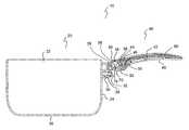
- FIG. 1is a perspective view of an exemplary embodiment of an articulating handle for cookware according to the present invention
- FIG. 2is an exploded perspective view of the handle illustrated in FIG. 1 ;
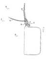
- FIG. 3is a side elevational view of the handle illustrated in FIG. 1 in a substantially vertical position
- FIG. 4is a top plan view of the handle illustrated in FIG. 1 ;
- FIG. 5is a cross-sectional view of the handle illustrated in FIG. 4 ;
- FIG. 6is a cross-sectional view of the handle illustrated in FIG. 4 , wherein the locking lever is in the unlocked position;
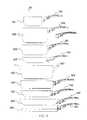
- FIG. 7is a top plan view of an exemplary embodiment of a nested arrangement of cookware pieces having articulating handles according to the present invention.
- FIG. 8is a side elevational view of the nested arrangement illustrated in FIG. 7 ;
- FIG. 9is an exploded view of the nested arrangement illustrated in FIG. 7 .
- FIGS. 1-6disclose an exemplary embodiment of a space-saving cookware 10 according to the present invention. Such an embodiment saves space within storage cabinets and permits multiple cookware pieces to be neatly stacked and stored within the cabinets.
- the exemplary cookware 10includes a receptacle 20 and an articulating handle assembly 40 .
- Receptacle 20may include a sidewall 24 , bottom wall 26 , a reservoir 22 formed by sidewall 24 and bottom wall 26 , and a hinge assembly receiving device 28 connected to the sidewall.
- Hinge assembly receiving device 28may be connected to sidewall 24 by any conventional device or method known to one of ordinary skill in the art, including but not limited to a rivet, screw, bolt, welding, brazing, etc.
- receptacle 20may comprise, but is not limited to, pots, pans, boilers, woks, griddles or any other cookware as known to one of ordinary skill in the art.
- receptacle 20may be fabricated from any conventional materials used in cookware such as metals, metals coated with non-stick material and/or other materials as known to one of ordinary skill in the art.
- cookware 10may include a hinge assembly 30 that is connected to sidewall 24 of receptacle 20 using a fastener 32 that connects hinge assembly 30 to hinge assembly receiving device 28 .
- hinge assembly 30may be connected to sidewall 24 by any conventional device or method known to one of ordinary skill in the art, including but not limited to a rivet, screw, bolt, welding, brazing, etc.
- fastener 32is a screw that is threadingly received into hinge assembly receiving device 28 .
- hinge pin 34may include multiple detents in order to permit handle assembly 40 to lock into multiple positions along the hinge pin.
- Handle assembly 40is configured such that when connected to receptacle 20 via hinge assembly 30 , it may rotate about hinge pin 34 .
- handle assembly 40rotates about hinge pin 34 between the substantially horizontal position (e.g., FIGS. 1 and 5 ) or the substantially vertical position ( FIG. 3 ).
- Handle assembly 40includes a locking lever 42 , a locking cam 44 connected to locking lever 42 , an upper clamp 60 , a lower clamp 70 rotatably connected to upper clamp 60 , a clamp actuator 50 , and a handle grip 80 attached to an underside 66 of upper clamp 60 .
- Lower clamp 70includes a first lower clamp end 72 , a lower clamp hole 74 , and a protrusion 75 .
- Lower clamp 70is formed such that a portion of its body substantially confirms to the shape of hinge pin 34 and that protrusion 75 extends inwardly from an inside surface 73 of clamp 70 .
- Protrusion 75is configured to engage detents 36 and 38 in order to stop and/or lock handle assembly 40 into the substantially horizontal and vertical positions, respectively.
- Upper clamp 60includes a first upper clamp end 62 and a hollow 64 disposed within upper clamp 60 . At first clamp end 62 , upper clamp 60 is formed to substantially conform to the shape of hinge pin 34 . Upper clamp 60 and lower clamp 70 are rotatably connected to each other at upper and lower first ends 62 and 72 using clamp pin 78 such that they encompass hinge pin 34 in order to rotatably connect handle assembly 40 to receptacle 20 .
- Clamp actuator 50in the exemplary embodiment, includes a first actuator end 54 at one end and a head 52 at an end opposite the first actuator end. Clamp actuator 50 and head 52 may comprise a bolt and head, respectively. It is understood that other devices may be used for clamp actuator 50 and head 52 as known to one of ordinary skill in the art.
- Locking lever 42includes a hinge pin hole 48 disposed near cam 44 .
- Locking lever 42is rotatably connected to clamp actuator 50 and upper clamp 60 within hollow 64 using a lever hinge pin 46 that is disposed through pin hole 48 and actuator first end 54 and connects the lever to upper clamp 60 .
- clamp actuator 50is disposed through an aperture (not shown) in upper clamp aperture 60 within hollow 64 and through lower clamp hole 74 such that head 52 engages an outer surface 76 of lower clamp 70 . As such, clamp actuator 50 causes upper clamp 60 and lower clamp 70 to substantially encompass hinge pin 34 .
- lever 42In operation, when lever 42 is moved to the unlock position as shown in FIG. 6 , cam 44 moves actuator 50 such that head 52 disengages outer surface 76 , permitting the upper and lower clamps to move apart or partially separate. When upper and lower clamps 60 and 70 , respectively, move apart, protrusion 75 disengages detents 36 and/or 38 , which permits handle assembly 40 to rotate about hinge pin 34 . For example, if handle assembly 40 is locked in a substantially horizontal position shown in FIG. 1 , lever 42 may be moved up and away from upper clamp 60 to the unlocked position, and handle assembly 40 may be rotated to the vertical position shown in FIG. 3 .
- lever 42may be moved back toward upper clamp 60 into the locked position, wherein the upper and lower clamps close, tighten around, and/or clamp onto hinge pin 34 .
- This closing of upper and lower clamps 60 and 70cause protrusion 75 to engage detent 38 , locking the handle assembly in the substantially vertical position.
- the processmay be repeated to cause protrusion 75 to engage detent 36 , locking handle assembly 40 into the substantially horizontal position.
- hinge assembly 30handle assembly 40 and any or all of their components may be fabricated from a variety of conventional materials, including but not limited to metals, plastics, ceramics, composite materials, any combinations thereof, or any other materials as known to one of ordinary skill in the art.
- the upper clamp, lower clamp, and actuatorare fabricated from aluminum
- the locking leveris fabricated from stainless steel
- the handle gripis fabricated from plastic.
- Nested arrangement 90may include multiple cookware pieces having articulated handles as described herein.
- the exemplary embodimentincludes nine (9) cookware pieces ( 100 , 200 , 300 , 400 , 500 , 600 , 700 , 800 and 900 ), wherein the size, e.g., the diameter of the receptacle, may increase in ascending order.
- cookware piece 100is the smallest (e.g., smallest diameter)
- cookware piece 200is slightly larger in size compared to piece 100 (e.g., larger diameter than cookware piece 100 ) and so on.
- the nested arrangementis assembled such that each correspondingly smaller cookware piece fits within and is placed within the next correspondingly larger cookware piece.
- piece 100is placed within the receptacle of piece 200 , which is placed within the receptacle of piece 300 , which is placed within the receptacle of piece 400 and so on until the nested arrangement includes all nine (9) pieces.
- a plurality of the cookware piecesincludes articulated handle assemblies (e.g., handle assemblies 102 , 202 , 302 , 402 , 502 , 602 , 702 , 802 and 902 ) that when rotated to the substantially vertical position may fit within the next correspondingly larger cookware piece's receptacle as shown in FIGS. 7 and 8 .
- articulated handle assembliese.g., handle assemblies 102 , 202 , 302 , 402 , 502 , 602 , 702 , 802 and 902
- Such a configurationreduces the overall height (H) of nested arrangement of cookware pieces 90 but also the length (L) and width (W).
- the height (H) of the exemplaryis approximately 336 mm
- the length (L)is approximately 360 mm
- the widthis approximately 313 mm.
- nested arrangement 90occupies a volume of space less than 0.04 m 3 , in another exemplary less than or equal to 0.0379 m 3 .
- the present inventionsaves shelf space and provides for a user to neatly stack a plurality of cookware pieces having a variety of sizes and shapes.
Landscapes
- Engineering & Computer Science (AREA)
- Food Science & Technology (AREA)
- Cookers (AREA)
Abstract
Description
Claims (12)
Priority Applications (1)
| Application Number | Priority Date | Filing Date | Title |
|---|---|---|---|
| US11/715,170US8011530B2 (en) | 2006-03-10 | 2007-03-07 | Articulating handle for space-saving cookware and method for using same |
Applications Claiming Priority (2)
| Application Number | Priority Date | Filing Date | Title |
|---|---|---|---|
| US78145306P | 2006-03-10 | 2006-03-10 | |
| US11/715,170US8011530B2 (en) | 2006-03-10 | 2007-03-07 | Articulating handle for space-saving cookware and method for using same |
Publications (2)
| Publication Number | Publication Date |
|---|---|
| US20080179211A1 US20080179211A1 (en) | 2008-07-31 |
| US8011530B2true US8011530B2 (en) | 2011-09-06 |
Family
ID=39666725
Family Applications (1)
| Application Number | Title | Priority Date | Filing Date |
|---|---|---|---|
| US11/715,170Expired - Fee RelatedUS8011530B2 (en) | 2006-03-10 | 2007-03-07 | Articulating handle for space-saving cookware and method for using same |
Country Status (1)
| Country | Link |
|---|---|
| US (1) | US8011530B2 (en) |
Cited By (10)
| Publication number | Priority date | Publication date | Assignee | Title |
|---|---|---|---|---|
| US20120073085A1 (en)* | 2009-04-27 | 2012-03-29 | La Termoplastic F. B. M. S. R. L. | System for attaching and releasing the handle of a container for cooking food |
| US20130228581A1 (en)* | 2012-03-02 | 2013-09-05 | Charles HINZMAN | Cooking utensil with rotatable handle |
| US20150313403A1 (en)* | 2013-05-02 | 2015-11-05 | Jong Peter Park | Click and lock cookware handles |
| US20200115107A1 (en)* | 2018-10-12 | 2020-04-16 | O&M Halyard, Inc. | Ergonomic Handles for Containers |
| US11304549B2 (en) | 2018-10-22 | 2022-04-19 | Misaine Innovation Taiwan Co., Ltd. | Cup |
| US11337559B2 (en)* | 2019-10-16 | 2022-05-24 | Ariel Martin | Removable handles system |
| US20220257061A1 (en)* | 2016-07-13 | 2022-08-18 | Sea To Summit Pty Ltd | Handle for a container, hand-tool or other like item |
| USD1047581S1 (en) | 2023-04-14 | 2024-10-22 | Sea To Summit Pty Ltd | Cookware handle |
| USD1047582S1 (en) | 2023-04-14 | 2024-10-22 | Sea To Summit Pty Ltd | Cookware handle mount |
| USD1047584S1 (en) | 2023-04-14 | 2024-10-22 | Sea To Summit Pty Ltd | Cookware handle |
Families Citing this family (19)
| Publication number | Priority date | Publication date | Assignee | Title |
|---|---|---|---|---|
| US20090065509A1 (en)* | 2007-09-06 | 2009-03-12 | Bradshaw International, Inc. | Collapsible cookware |
| USD639109S1 (en) | 2010-07-14 | 2011-06-07 | Tabletops Unlimited, Inc. | Stacking set of cookware |
| USD641201S1 (en) | 2010-07-14 | 2011-07-12 | Tabletops Unlimited, Inc. | Stacking set of cookware |
| USD640896S1 (en) | 2010-07-14 | 2011-07-05 | Tabletops Unlimited, Inc. | Stacking set of cookware |
| USD639108S1 (en) | 2010-07-14 | 2011-06-07 | Tabletops Unlimited, Inc. | Stacking set of cookware |
| USD635819S1 (en) | 2010-08-26 | 2011-04-12 | Tabletops Unlimited, Inc. | Stacking set of bakeware |
| USD646525S1 (en) | 2010-08-26 | 2011-10-11 | Tabletops Unlimited, Inc. | Stacking bowl and colander set |
| USD635820S1 (en) | 2010-08-26 | 2011-04-12 | Tabletops Unlimited, Inc. | Stacking set of bakeware |
| FR2965467B1 (en)* | 2010-10-01 | 2012-11-02 | Seb Sa | PIVOTING HANDLE WITH ASSEMBLY RATCHET |
| CN103536226B (en)* | 2013-10-30 | 2016-08-17 | 浙江苏泊尔橡塑制品有限公司 | A kind of foldable handle of cooker |
| US9521931B2 (en)* | 2014-03-04 | 2016-12-20 | Allure Home Creation Co., Inc. | Detachable sleeve |
| US10486857B2 (en)* | 2016-02-25 | 2019-11-26 | Calphalon Corporation | Stackable cookware and lids |
| US20170280940A1 (en)* | 2016-03-31 | 2017-10-05 | Justin Quinn | Culinary vessels with quick release detachable handles |
| US10351299B2 (en)* | 2016-12-21 | 2019-07-16 | Yitzchak JACOBSON | Nestable pot set |
| US11517153B2 (en)* | 2017-01-03 | 2022-12-06 | Gregory Darren Koke | Removable handle for cooking utensil |
| US11039706B2 (en) | 2018-12-19 | 2021-06-22 | E. Mishan & Sons, Inc. | Stackable and nestable cookware having a stable configuration |
| USD879546S1 (en)* | 2019-01-02 | 2020-03-31 | E. Mishan & Sons, Inc. | Stackable cookware |
| US20230087271A1 (en)* | 2021-09-21 | 2023-03-23 | Vincent Lanteri, JR. | Frying Pan Device with Repositionable Handle |
| USD1021514S1 (en)* | 2023-07-30 | 2024-04-09 | Mambate US Inc. | Camping cookware |
Citations (18)
| Publication number | Priority date | Publication date | Assignee | Title |
|---|---|---|---|---|
| US582076A (en)* | 1897-05-04 | Clampind attachment for kettle-bails | ||
| US1077946A (en)* | 1911-10-09 | 1913-11-04 | Philip J Boyle | Culinary utensil. |
| US1181806A (en)* | 1915-08-30 | 1916-05-02 | Daniel W Smithers | Strainer. |
| US1348813A (en)* | 1920-08-03 | Necticut | ||
| US1479628A (en)* | 1922-05-12 | 1924-01-01 | Seger Ludwig | Hinge lock |
| US2299584A (en)* | 1942-03-28 | 1942-10-20 | Otto M Low | Folding ladder |
| US2403191A (en)* | 1943-09-07 | 1946-07-02 | Alvin W Phillips | Cooking utensil |
| US2881945A (en)* | 1957-02-19 | 1959-04-14 | Aaron B Rappaport | Kitchenware safety handle |
| US2915001A (en)* | 1957-11-25 | 1959-12-01 | Leonard W Montgomery | Cooking utensil |
| US3812997A (en)* | 1972-01-05 | 1974-05-28 | Nally V Mc | Combination shipping and cooking container |
| US4222493A (en)* | 1976-04-29 | 1980-09-16 | Conchetta Friedman | Cookware |
| US4724576A (en)* | 1986-05-27 | 1988-02-16 | Nitto Aluminium Mfg. Co., Ltd. | Handle of a pot |
| US5660300A (en)* | 1995-12-12 | 1997-08-26 | Demetrio; Bruno | Nestable cooking utensil with an articulable handle |
| US6079590A (en)* | 1998-03-27 | 2000-06-27 | La Termoplastic F.B.M. S.R.L. | Grip device for a food cooking vessel, in particular a frying-pan |
| US6220477B1 (en)* | 1999-12-02 | 2001-04-24 | Mark H. Schneider | Flip-handle cookware |
| US6526876B2 (en)* | 2001-06-05 | 2003-03-04 | W. C. Bradley Company | Handle for cookware |
| US20050167435A1 (en)* | 2004-01-30 | 2005-08-04 | Dave Whitmer | Locking cookware article |
| US7090094B2 (en)* | 2004-02-20 | 2006-08-15 | Main Power Electrical Factory Ltd. | Handle for cookware |
- 2007
- 2007-03-07USUS11/715,170patent/US8011530B2/ennot_activeExpired - Fee Related
Patent Citations (18)
| Publication number | Priority date | Publication date | Assignee | Title |
|---|---|---|---|---|
| US582076A (en)* | 1897-05-04 | Clampind attachment for kettle-bails | ||
| US1348813A (en)* | 1920-08-03 | Necticut | ||
| US1077946A (en)* | 1911-10-09 | 1913-11-04 | Philip J Boyle | Culinary utensil. |
| US1181806A (en)* | 1915-08-30 | 1916-05-02 | Daniel W Smithers | Strainer. |
| US1479628A (en)* | 1922-05-12 | 1924-01-01 | Seger Ludwig | Hinge lock |
| US2299584A (en)* | 1942-03-28 | 1942-10-20 | Otto M Low | Folding ladder |
| US2403191A (en)* | 1943-09-07 | 1946-07-02 | Alvin W Phillips | Cooking utensil |
| US2881945A (en)* | 1957-02-19 | 1959-04-14 | Aaron B Rappaport | Kitchenware safety handle |
| US2915001A (en)* | 1957-11-25 | 1959-12-01 | Leonard W Montgomery | Cooking utensil |
| US3812997A (en)* | 1972-01-05 | 1974-05-28 | Nally V Mc | Combination shipping and cooking container |
| US4222493A (en)* | 1976-04-29 | 1980-09-16 | Conchetta Friedman | Cookware |
| US4724576A (en)* | 1986-05-27 | 1988-02-16 | Nitto Aluminium Mfg. Co., Ltd. | Handle of a pot |
| US5660300A (en)* | 1995-12-12 | 1997-08-26 | Demetrio; Bruno | Nestable cooking utensil with an articulable handle |
| US6079590A (en)* | 1998-03-27 | 2000-06-27 | La Termoplastic F.B.M. S.R.L. | Grip device for a food cooking vessel, in particular a frying-pan |
| US6220477B1 (en)* | 1999-12-02 | 2001-04-24 | Mark H. Schneider | Flip-handle cookware |
| US6526876B2 (en)* | 2001-06-05 | 2003-03-04 | W. C. Bradley Company | Handle for cookware |
| US20050167435A1 (en)* | 2004-01-30 | 2005-08-04 | Dave Whitmer | Locking cookware article |
| US7090094B2 (en)* | 2004-02-20 | 2006-08-15 | Main Power Electrical Factory Ltd. | Handle for cookware |
Cited By (15)
| Publication number | Priority date | Publication date | Assignee | Title |
|---|---|---|---|---|
| US20120073085A1 (en)* | 2009-04-27 | 2012-03-29 | La Termoplastic F. B. M. S. R. L. | System for attaching and releasing the handle of a container for cooking food |
| US8484805B2 (en)* | 2009-04-27 | 2013-07-16 | La Termoplastic F.B.M. S.R.L. | System for attaching and releasing the handle of a container for cooking food |
| US20130228581A1 (en)* | 2012-03-02 | 2013-09-05 | Charles HINZMAN | Cooking utensil with rotatable handle |
| US8950621B2 (en)* | 2012-03-02 | 2015-02-10 | Charles HINZMAN | Cooking utensil with rotatable handle |
| US20150313403A1 (en)* | 2013-05-02 | 2015-11-05 | Jong Peter Park | Click and lock cookware handles |
| US20220257061A1 (en)* | 2016-07-13 | 2022-08-18 | Sea To Summit Pty Ltd | Handle for a container, hand-tool or other like item |
| US11771267B2 (en)* | 2016-07-13 | 2023-10-03 | Sea To Summit Pty Ltd | Handle for a container, hand-tool or other like item |
| US10683138B2 (en)* | 2018-10-12 | 2020-06-16 | O&M Halyard, Inc. | Ergonomic handles for containers |
| US20200115107A1 (en)* | 2018-10-12 | 2020-04-16 | O&M Halyard, Inc. | Ergonomic Handles for Containers |
| US11304549B2 (en) | 2018-10-22 | 2022-04-19 | Misaine Innovation Taiwan Co., Ltd. | Cup |
| US11337559B2 (en)* | 2019-10-16 | 2022-05-24 | Ariel Martin | Removable handles system |
| USD1047581S1 (en) | 2023-04-14 | 2024-10-22 | Sea To Summit Pty Ltd | Cookware handle |
| USD1047582S1 (en) | 2023-04-14 | 2024-10-22 | Sea To Summit Pty Ltd | Cookware handle mount |
| USD1047584S1 (en) | 2023-04-14 | 2024-10-22 | Sea To Summit Pty Ltd | Cookware handle |
| USD1047583S1 (en) | 2023-04-14 | 2024-10-22 | Sea To Summit Pty Ltd | Cookware handle coupling mechanism |
Also Published As
| Publication number | Publication date |
|---|---|
| US20080179211A1 (en) | 2008-07-31 |
Similar Documents
| Publication | Publication Date | Title |
|---|---|---|
| US8011530B2 (en) | Articulating handle for space-saving cookware and method for using same | |
| US8413840B2 (en) | Handle for cookware | |
| US11548685B2 (en) | Stackable tote and lid combination | |
| US10486857B2 (en) | Stackable cookware and lids | |
| US8746498B2 (en) | Coolers with storage hooks | |
| US9393684B2 (en) | Toolbox | |
| US11523616B2 (en) | Folding pizza peel | |
| AU640556B2 (en) | A stackable and collapsible shelf | |
| US10463228B2 (en) | Wine glass drying rack | |
| EP0129484A1 (en) | Filing cabinet with multiple compartments | |
| US20090095754A1 (en) | Stackable cover for container | |
| KR20070101643A (en) | Storage container | |
| US8322564B2 (en) | Cooking article with folding handle | |
| USD517806S1 (en) | Flatten basket | |
| US20140312067A1 (en) | Stackable Liquid Pitcher | |
| US10398258B2 (en) | Handle and container with handle | |
| US20120037643A1 (en) | Cooler with tray | |
| US20030173320A1 (en) | Space-saving rack | |
| US8827098B2 (en) | Collapsible lid handle for cookware | |
| CA2715583A1 (en) | Container with a retractable handle | |
| KR101554327B1 (en) | Multiple-stage airtight container | |
| US20210030211A1 (en) | Stackable frying pans and saucepans | |
| US20050188857A1 (en) | Container for gastronomic use | |
| US20230087271A1 (en) | Frying Pan Device with Repositionable Handle | |
| KR200484789Y1 (en) | Multistage type food container |
Legal Events
| Date | Code | Title | Description |
|---|---|---|---|
| AS | Assignment | Owner name:SEB S.A., FRANCE Free format text:ASSIGNMENT OF ASSIGNORS INTEREST;ASSIGNORS:KUTSCH, DUANE;KEIDL, CHRISTOPHER;REEL/FRAME:023386/0842;SIGNING DATES FROM 20070520 TO 20070525 Owner name:GROUPE SEB USA, NEW JERSEY Free format text:ASSIGNMENT OF ASSIGNORS INTEREST;ASSIGNORS:KUTSCH, DUANE;KEIDL, CHRISTOPHER;REEL/FRAME:023386/0842;SIGNING DATES FROM 20070520 TO 20070525 Owner name:SEB S.A., FRANCE Free format text:ASSIGNMENT OF ASSIGNORS INTEREST;ASSIGNORS:KUTSCH, DUANE;KEIDL, CHRISTOPHER;SIGNING DATES FROM 20070520 TO 20070525;REEL/FRAME:023386/0842 Owner name:GROUPE SEB USA, NEW JERSEY Free format text:ASSIGNMENT OF ASSIGNORS INTEREST;ASSIGNORS:KUTSCH, DUANE;KEIDL, CHRISTOPHER;SIGNING DATES FROM 20070520 TO 20070525;REEL/FRAME:023386/0842 | |
| ZAAA | Notice of allowance and fees due | Free format text:ORIGINAL CODE: NOA | |
| ZAAB | Notice of allowance mailed | Free format text:ORIGINAL CODE: MN/=. | |
| STCF | Information on status: patent grant | Free format text:PATENTED CASE | |
| CC | Certificate of correction | ||
| FPAY | Fee payment | Year of fee payment:4 | |
| MAFP | Maintenance fee payment | Free format text:PAYMENT OF MAINTENANCE FEE, 8TH YEAR, LARGE ENTITY (ORIGINAL EVENT CODE: M1552); ENTITY STATUS OF PATENT OWNER: LARGE ENTITY Year of fee payment:8 | |
| FEPP | Fee payment procedure | Free format text:MAINTENANCE FEE REMINDER MAILED (ORIGINAL EVENT CODE: REM.); ENTITY STATUS OF PATENT OWNER: LARGE ENTITY | |
| LAPS | Lapse for failure to pay maintenance fees | Free format text:PATENT EXPIRED FOR FAILURE TO PAY MAINTENANCE FEES (ORIGINAL EVENT CODE: EXP.); ENTITY STATUS OF PATENT OWNER: LARGE ENTITY | |
| STCH | Information on status: patent discontinuation | Free format text:PATENT EXPIRED DUE TO NONPAYMENT OF MAINTENANCE FEES UNDER 37 CFR 1.362 | |
| FP | Lapsed due to failure to pay maintenance fee | Effective date:20230906 |