US8011032B2 - Energy efficient circulation system for spas and hot tubs - Google Patents
Energy efficient circulation system for spas and hot tubsDownload PDFInfo
- Publication number
- US8011032B2 US8011032B2US11/750,255US75025507AUS8011032B2US 8011032 B2US8011032 B2US 8011032B2US 75025507 AUS75025507 AUS 75025507AUS 8011032 B2US8011032 B2US 8011032B2
- Authority
- US
- United States
- Prior art keywords
- water
- pump
- assembly
- housing structure
- tub
- Prior art date
- Legal status (The legal status is an assumption and is not a legal conclusion. Google has not performed a legal analysis and makes no representation as to the accuracy of the status listed.)
- Expired - Fee Related, expires
Links
- XLYOFNOQVPJJNP-UHFFFAOYSA-NwaterSubstancesOXLYOFNOQVPJJNP-UHFFFAOYSA-N0.000claimsabstractdescription117
- 238000003287bathingMethods0.000claimsabstractdescription36
- 238000009434installationMethods0.000claimsabstractdescription16
- 238000012546transferMethods0.000claimsabstractdescription4
- 239000012530fluidSubstances0.000claimsdescription20
- 238000004891communicationMethods0.000claimsdescription10
- 238000009429electrical wiringMethods0.000claimsdescription4
- 238000001914filtrationMethods0.000claimsdescription4
- 238000010438heat treatmentMethods0.000claimsdescription3
- 239000002918waste heatSubstances0.000claimsdescription3
- 239000012774insulation materialSubstances0.000claims2
- 238000007789sealingMethods0.000claims2
- 238000005265energy consumptionMethods0.000claims1
- 239000012535impuritySubstances0.000claims1
- 238000000034methodMethods0.000abstractdescription4
- 230000003750conditioning effectEffects0.000description15
- 238000009413insulationMethods0.000description4
- 238000010586diagramMethods0.000description3
- 238000001816coolingMethods0.000description2
- 238000007667floatingMethods0.000description2
- 238000007710freezingMethods0.000description2
- 230000008014freezingEffects0.000description2
- 239000000463materialSubstances0.000description2
- 239000000853adhesiveSubstances0.000description1
- 230000001070adhesive effectEffects0.000description1
- 238000010276constructionMethods0.000description1
- 238000013461designMethods0.000description1
- 230000007613environmental effectEffects0.000description1
- 239000006260foamSubstances0.000description1
- 239000008236heating waterSubstances0.000description1
- 230000013011matingEffects0.000description1
- 238000012986modificationMethods0.000description1
- 230000004048modificationEffects0.000description1
- 238000000465mouldingMethods0.000description1
- 238000009428plumbingMethods0.000description1
- 229920000728polyesterPolymers0.000description1
- 238000003825pressingMethods0.000description1
- 238000009877renderingMethods0.000description1
- 238000003466weldingMethods0.000description1
Images


Classifications
- E—FIXED CONSTRUCTIONS
- E04—BUILDING
- E04H—BUILDINGS OR LIKE STRUCTURES FOR PARTICULAR PURPOSES; SWIMMING OR SPLASH BATHS OR POOLS; MASTS; FENCING; TENTS OR CANOPIES, IN GENERAL
- E04H4/00—Swimming or splash baths or pools
- E04H4/12—Devices or arrangements for circulating water, i.e. devices for removal of polluted water, cleaning baths or for water treatment
- E04H4/129—Systems for heating the water content of swimming pools
- A—HUMAN NECESSITIES
- A61—MEDICAL OR VETERINARY SCIENCE; HYGIENE
- A61H—PHYSICAL THERAPY APPARATUS, e.g. DEVICES FOR LOCATING OR STIMULATING REFLEX POINTS IN THE BODY; ARTIFICIAL RESPIRATION; MASSAGE; BATHING DEVICES FOR SPECIAL THERAPEUTIC OR HYGIENIC PURPOSES OR SPECIFIC PARTS OF THE BODY
- A61H33/00—Bathing devices for special therapeutic or hygienic purposes
- A61H33/60—Components specifically designed for the therapeutic baths of groups A61H33/00
- A—HUMAN NECESSITIES
- A61—MEDICAL OR VETERINARY SCIENCE; HYGIENE
- A61H—PHYSICAL THERAPY APPARATUS, e.g. DEVICES FOR LOCATING OR STIMULATING REFLEX POINTS IN THE BODY; ARTIFICIAL RESPIRATION; MASSAGE; BATHING DEVICES FOR SPECIAL THERAPEUTIC OR HYGIENIC PURPOSES OR SPECIFIC PARTS OF THE BODY
- A61H33/00—Bathing devices for special therapeutic or hygienic purposes
- A61H2033/0037—Arrangement for cleaning the fluid during use
- A—HUMAN NECESSITIES
- A61—MEDICAL OR VETERINARY SCIENCE; HYGIENE
- A61H—PHYSICAL THERAPY APPARATUS, e.g. DEVICES FOR LOCATING OR STIMULATING REFLEX POINTS IN THE BODY; ARTIFICIAL RESPIRATION; MASSAGE; BATHING DEVICES FOR SPECIAL THERAPEUTIC OR HYGIENIC PURPOSES OR SPECIFIC PARTS OF THE BODY
- A61H2201/00—Characteristics of apparatus not provided for in the preceding codes
- A61H2201/02—Characteristics of apparatus not provided for in the preceding codes heated or cooled
- A61H2201/0207—Characteristics of apparatus not provided for in the preceding codes heated or cooled heated
- A—HUMAN NECESSITIES
- A61—MEDICAL OR VETERINARY SCIENCE; HYGIENE
- A61H—PHYSICAL THERAPY APPARATUS, e.g. DEVICES FOR LOCATING OR STIMULATING REFLEX POINTS IN THE BODY; ARTIFICIAL RESPIRATION; MASSAGE; BATHING DEVICES FOR SPECIAL THERAPEUTIC OR HYGIENIC PURPOSES OR SPECIFIC PARTS OF THE BODY
- A61H2201/00—Characteristics of apparatus not provided for in the preceding codes
- A61H2201/02—Characteristics of apparatus not provided for in the preceding codes heated or cooled
- A61H2201/0221—Mechanism for heating or cooling
- A61H2201/0242—Mechanism for heating or cooling by a fluid circulating in the apparatus
- A—HUMAN NECESSITIES
- A61—MEDICAL OR VETERINARY SCIENCE; HYGIENE
- A61H—PHYSICAL THERAPY APPARATUS, e.g. DEVICES FOR LOCATING OR STIMULATING REFLEX POINTS IN THE BODY; ARTIFICIAL RESPIRATION; MASSAGE; BATHING DEVICES FOR SPECIAL THERAPEUTIC OR HYGIENIC PURPOSES OR SPECIFIC PARTS OF THE BODY
- A61H2201/00—Characteristics of apparatus not provided for in the preceding codes
- A61H2201/50—Control means thereof
- A61H2201/5007—Control means thereof computer controlled
- A—HUMAN NECESSITIES
- A61—MEDICAL OR VETERINARY SCIENCE; HYGIENE
- A61H—PHYSICAL THERAPY APPARATUS, e.g. DEVICES FOR LOCATING OR STIMULATING REFLEX POINTS IN THE BODY; ARTIFICIAL RESPIRATION; MASSAGE; BATHING DEVICES FOR SPECIAL THERAPEUTIC OR HYGIENIC PURPOSES OR SPECIFIC PARTS OF THE BODY
- A61H2201/00—Characteristics of apparatus not provided for in the preceding codes
- A61H2201/50—Control means thereof
- A61H2201/5058—Sensors or detectors
- A61H2201/5082—Temperature sensors
- A—HUMAN NECESSITIES
- A61—MEDICAL OR VETERINARY SCIENCE; HYGIENE
- A61H—PHYSICAL THERAPY APPARATUS, e.g. DEVICES FOR LOCATING OR STIMULATING REFLEX POINTS IN THE BODY; ARTIFICIAL RESPIRATION; MASSAGE; BATHING DEVICES FOR SPECIAL THERAPEUTIC OR HYGIENIC PURPOSES OR SPECIFIC PARTS OF THE BODY
- A61H33/00—Bathing devices for special therapeutic or hygienic purposes
- A61H33/0087—Therapeutic baths with agitated or circulated water
- A—HUMAN NECESSITIES
- A61—MEDICAL OR VETERINARY SCIENCE; HYGIENE
- A61H—PHYSICAL THERAPY APPARATUS, e.g. DEVICES FOR LOCATING OR STIMULATING REFLEX POINTS IN THE BODY; ARTIFICIAL RESPIRATION; MASSAGE; BATHING DEVICES FOR SPECIAL THERAPEUTIC OR HYGIENIC PURPOSES OR SPECIFIC PARTS OF THE BODY
- A61H33/00—Bathing devices for special therapeutic or hygienic purposes
- A61H33/60—Components specifically designed for the therapeutic baths of groups A61H33/00
- A61H33/601—Inlet to the bath
Definitions
- Bathing installationssuch as spas and pools, may employ a circulation water flow path and a pump connected to pump water through the circulation water flow path.
- this circulation systemprovides movement of the water through a filter to clarify the water, and through a heater to facilitate effective heating of the water.
- a significant amount of heatmay be generated by the pump during operation, and the heat energy is typically wasted unless collected by a complex cooling system.
- FIG. 1is a diagrammatic side cross-sectional view of an exemplary embodiment of a water conditioning system for a bathing installation system.
- FIG. 1Ais a simplified schematic diagram illustrating an exemplary controller which controls operation of a heater and pump.
- FIG. 2is an enlarged view of a portion of the system illustrated in FIG. 1 .
- FIG. 3is an isometric view illustrating features of an exemplary alternative embodiment of a water conditioning system.
- FIG. 4is a diagrammatic view illustrating an alternative exemplary embodiment of a water conditioning system for a bathing installation.
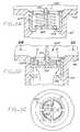
- FIG. 5is a broken-away diagram illustrating a portion of the water conditioning system of FIG. 4 .
- FIG. 6is a view illustrating an exemplary connection of the water conditioning system to a bathing installation.
- FIGS. 6A-6Cillustrate features of an exemplary check valve.
- FIG. 1An exemplary embodiment of a bathing installation 10 is diagrammatically depicted in FIG. 1 .
- the bathing installationwhich may be a spa system in an exemplary embodiment, includes a water receptacle 12 , e.g. a spa tub, for holding a body 14 of water.
- the bathing installationincludes a circulation water conditioning system 50 .
- the water conditioning systemmay include a housing structure 60 adapted to be connected to an opening 15 defined in the tub 12 .
- the housing structure 60may have a circular cross-section for ease of construction, but other configurations may alternatively be employed.
- the structure 60includes a main inlet port 62 , and an outlet port 64 , and has an interior chamber 61 .
- a floating skimmer or weir 70is positioned with a skimmer basket 72 at the inlet port 62 , and has an open top 70 A.
- waterenters the inlet port through the open top of the floating skimmer and passes through the skimmer basket 72 into the housing structure 60 , as generally indicated by arrows 54 A.
- the skimmer basketmay provide a coarse filtration of large foreign matter, such as leaves or other large items.
- a second filtration functionmay be provided in the conditioning system 50 , e.g., by a filter cartridge 80 enclosed within the housing structure 60 .
- the conditioning system 50further comprises, in this exemplary embodiment, a circulation pump 90 disposed within the housing structure.
- the housing structureis adapted to support the filter cartridge 80 and the pump such that water which enters the housing structure through the inlet port 62 passes through the filter cartridge 80 as indicated by arrows 54 B, and enters the pump 90 at pump inlet 92 .
- the pump 90has an outlet 94 , which is in fluid communication with the housing outlet port 64 .
- the housing structure 60may include a canister end cap 66 which is attached at an end of a generally cylindrical housing member or barrel member 60 A.
- the end cap 66is illustrated in further detail in the enlarged fragmentary view of FIG. 2 , and may be adapted to include an electrical wiring port 66 A at a bottom end thereof to allow an electrical cord 96 to pass through to a source of electrical power.
- the electrical power sourcemay be through a control system, as will be described more fully.
- a gasket or seal 98may be provided to prevent water from leaking through the port 66 A.
- FIG. 2depicts an exemplary mounting arrangement for the pump 90 within the housing structure 60 .
- the filter cartridge 80may include a bottom rigid plate member 82 having a hollow threaded male fitting 82 A.
- the filter cartridgemay include filter media 86 , which may be porous, and serve to capture particulates from water passing through the filter cartridge.
- Filter cartridges suitable for the purposeare commercially available. One example is the cartridge marketed by Unicel as the 7CH-402 cartridge. An example of suitable filter media is permeable polyester.
- a pump discharge housing 68may fit over one end of the pump, and include a threaded inlet port 68 A. The threaded fitting 82 A of the filter cartridge engages the threaded inlet port 68 A of the pump discharge housing to attach the filter cartridge to the pump housing.
- the inlet port 68 A of the housing 68is in fluid communication with the inlet port of the pump.
- the housing 68defines a pump chamber 95 which surrounds a pump impeller 99 which is rotated by the pump drive. The impeller rotation drives water entering the chamber 95 from inlet port 68 A to an outlet port or tube 68 B, which provides a conduit from the pump outlet port to the outlet port 64 of the housing structure 60 .
- the housing structure 60 , the canister end cap 66 and the pump discharge housing 68may each be fabricated by molding a plastic material.
- the outlet port 68 B of the pump discharge housing 68communicates with the canister end cap 66 by a slip fit.
- Pumps suitable for the purpose of pump 90are commercially available.
- One exemplary type of pumpis a magnetic drive pump, in which a power unit, typically encased in a water-tight case, creates a magnetic field which drives a magnetic impeller such as impeller 99 .
- Magnetic drive pumpsare marketed, e.g., by Danner Mfg. Inc., Islandia, N.Y.
- the housing structure 60( FIG. 1 ) is adapted to support the pump so that the pump is submerged in water which is flowing through the system 50 . Due to the physics of any electrical motor design configured to drive a pump, a portion of the electrical energy used in this manner is lost as heat. All electrical pumps must be designed with a cooling system to dissipate this heat, which if not captured in the water, will be lost.
- a significant portion of the exterior surface of the pump housing or pump bodyis in contact with water in the housing structure, which flows around the pump housing and passes into the pump inlet port 92 and is pumped out the output port 94 .
- the water flow around the pump housingis generally indicated by arrow 54 C in FIG.
- the water flow around the pump housingmay be a fraction of the total water flow through the system 50 , as some or most of the water passes directly through the filter cartridge into the pump inlet port. However, water in which the pump is submerged is in thermal contact with the pump housing, allowing heat transfer between the pump and the water. As heat is generated in the pump motor during operation of the pump, at least some of the heat energy, and preferably a large percentage, greater than 50%, of the heat energy, is transferred to the water.
- the water conditioning system 50may further include, in an exemplary embodiment, a heater system 100 ( FIG. 1 ) for actively heating water.
- the heater system 100may include an electrically powered heating element, powered by electric power delivered to heater terminals 104 .
- the heater systemmay include temperature sensors 102 A, 102 B located adjacent the input/output ports of the heater housing 106 .
- the temperature sensorsmay sense temperatures related to the temperature of water entering the heater system and the temperature of water exiting the heater system.
- a control systemmay process the temperature sensor signals, e.g. to determine whether water is present in or flowing through the heater system, and to call for heat in the event the water temperature is below a set point.
- Other sensorssuch as pressure or flow switches may be alternatively be employed to sense whether water is present in or flowing through the heater system.
- FIG. 1Ais a simplified schematic diagram illustrating an exemplary controller 300 which controls operation of the heater 100 and the pump 90 , and receives temperature data from one or more sensors 302 .
- the sensors 302may include temperature sensors providing temperature data indicative of the bathing water temperature, pressure switches, flow switches, water pH sensor, and the like.
- the controllermay be a microprocessor-based control system. Exemplary heater and control systems suitable for use are described in U.S. Pat. Nos. 7,030,343, 6,643,108 and 6,282,370, the entire contents of which are incorporated herein by reference. Other heater and control systems may alternatively be employed.
- the heater system 100may be connected to a source of electrical power.
- the heater systemmay be activated in a manner so as to maintain a desired or set water temperature in the tub.
- the temperaturemay be selected by the user, with a control panel, for example.
- the heater system 100in this exemplary embodiment has an input port connected to the pump output port by a fluid conduit 110 , and an output port connected to a port 16 in the tub wall by a fluid conduit 112 .
- the fluid conduits 110 , 112may be flexible or rigid conduits, or a combination of flexible and rigid conduits.
- FIG. 3depicts an exemplary embodiment in which flexible conduits 110 - 1 and 112 - 1 are employed to provide a fluid connection between the filter and pump housing structure and the heater system 100 , and between the heater system and the port 16 in the tub wall.
- the water conditioning system 50may include an equalizer port 65 for the housing structure 60 , and a fluid conduit 120 connected between the equalizer port 65 and a port 18 in the tub wall.
- the suddenly increased pressuremay cause water to be drawn into port 18 , through conduit 120 and into the equalizer port 65 , to be passed through the pump 90 , thus equalizing pressure at the input port 62 .
- a check valve 200may be included to prevent flow through the equalizer port until a certain backpressure exists in the housing 60 which is sufficient to overcome the break pressure of the check valve.
- the amount of power utilized by the bathing installationmay be reduced by the exemplary system depicted in FIG. 1 , in which the pump 90 is submerged in water passing through the conditioning system 50 . Heat energy generated by the pump may be transferred to the water in the housing structure 60 in which the pump is submerged. This in turn may reduce the heat load which is to be met by the heater system 100 . Depending on the set point temperature for the bathing installation and the environmental factors such as external temperature, whether the reservoir is covered, and the amount and effectiveness of any insulation, under some circumstances it may even be unnecessary to run the heater system 100 to meet the set point temperature. The amount of energy to meet the heat demands may be reduced.
- the housing structure 60may include a top bracket 63 which may be secured to the tub by engagement of a threaded nut 65 engaging external threads formed on the outer surface of the housing at the tub end of the housing structure 60 , tightening flange 67 against the tub surface surrounding the opening 15 .
- the pump 90may be fitted to a lower pump housing 69 which is fastened to the canister end cap 66 , e.g. by an opposed pair of threaded fasteners 69 A ( FIG. 2 ).
- the installation connections for the pump 90 in the housing structure 60are the pressure outlet to the heater 100 through outlet port 68 B of the pump discharge housing 68 , and port 66 A sealed by O ring 98 , which is a generally circular opening in the bottom of the filter vessel, through which passes the electrical cord 96 . Because both of these connections are slip engaged, the means of assembly of this exemplary embodiment is extremely simple, including feeding the power wire 96 through the port 66 A, lowering the pump 90 down into the housing structure through the inlet 62 , and pressing the pump into place. Although fasteners may be employed, it is also contemplated that the friction of the engagement into the ports 64 and 66 A may be adequate to retain the pump in place.
- the skimmer weir 70 and skimmer basket 72may be removable from the housing structure 60 , permitting access to the filter cartridge 80 , e.g. to remove/replace the cartridge.
- the cartridge 80may be removed by grasping the handle 87 ( FIG. 1 ) of the cartridge and rotating the cartridge to disengage the fitting 82 A from the inlet port of the pump discharge housing. After the cartridge is lifted out of the housing 60 , the pump may be removed for servicing, by removing the screws 69 A, unplugging the power cord connector, and lifting the pump 90 out of the housing.
- FIGS. 4-6Cillustrate features of another exemplary embodiment of a water conditioning system 150 .
- This embodimentincludes a housing structure 160 adapted to support the filter cartridge 80 and the pump 90 in a fluid flow path within the housing.
- This embodimentdiffers from the embodiment of FIGS. 1-3 , in that the equalizer port 165 is located at the bottom of the canister end cap 166 , instead of being located on the side of the housing barrel.
- the housing structure 160includes a generally cylindrical barrel member 160 A, a top bracket 163 attached to the top end of the barrel member for attaching the housing structure 160 to the tub 12 , and the canister end cap 166 attached to the lower end of the barrel member.
- the top bracket, the barrel member and the canister end capmay, in an exemplary embodiment, be fabricated of a plastic material, and connected together by welding, adhesive, clamping or other suitable connection technique.
- a pump discharge housing 168secures the pump 90 to the canister end cap, and the electrical power cord for the pump is passed out through port 166 A.
- the pump outletflows from outlet port 164 .
- a check valve 200is disposed in the equalizer port 165 .
- FIGS. 6A-6CAn exemplary embodiment of check valve 200 is illustrated in FIGS. 6A-6C .
- the check valveincludes a movable valve member 202 positioned in a normally closed position ( FIG. 6A ) against seat 206 by a bias spring 204 .
- a check valve break pressuredetermined by the spring constant of spring 204
- the valve membermoves away from seat 206 , permitting water flow through valve web 210 as illustrated in the open position in FIG. 6B .
- other check valve configurationsmay alternatively be employed.
- the water conditioning systemmay include a heater system 110 , as illustrated in FIG. 6 , coupled to outlet port 164 by fluid conduit 180 , and to tub inlet port 16 by fluid conduit 190 .
- the equalizer port 165may be coupled to the tub port 18 by fluid conduit 170 .
- the fluid conduitsmay be flexible tubing structures, rigid tubing structures, or a combination of flexible and rigid conduits.
- the pump 90is completely submerged in the bathing water contained within the housing structure 160 , which is surrounded by foam insulation 400 .
- the water in the housing structureis protected from freezing temperatures by the insulation 400 and the spa skirt 401 surrounding the housing structure and other components of the spa. Therefore, plumbing lines in the circulation path with the pump are not likely to freeze up unless the power outage lasts an extraordinary long time.
- the insulation 400may be omitted from spaces such as space 410 , 412 to allow ready access to spa components such as the heater assembly 100 and a controller 300 .
- a conduit 96 Bmay be provided, in which the pump wiring 96 is run from the port 166 A to a junction box 320 mounted in space 410 .
- Electrical wiring 322may run between the junction box 320 and the controller 300 , in an exemplary embodiment in which the controller includes electrical service and switching for the pump 90 .
- a plug or connector 96 A for pump wiring 96may connect to a mating electrical connector in the junction box 320 , and may be disconnected and reconnected to allow removal and installation of a pump 90 from the housing structure 60 .
- the pump wiring 96may be fished through the conduit 96 B for the removal/installation procedure.
- the controller 300may be mounted adjacent to the heater assembly 100 , and in this case, the conduit 96 B may be run to the space 412 .
- the pump wiring 96may be attached to terminal blocks by pressure connectors.
Landscapes
- Engineering & Computer Science (AREA)
- Health & Medical Sciences (AREA)
- Life Sciences & Earth Sciences (AREA)
- Public Health (AREA)
- Architecture (AREA)
- General Health & Medical Sciences (AREA)
- Rehabilitation Therapy (AREA)
- Animal Behavior & Ethology (AREA)
- Physical Education & Sports Medicine (AREA)
- Veterinary Medicine (AREA)
- Sustainable Development (AREA)
- Pain & Pain Management (AREA)
- Water Supply & Treatment (AREA)
- Epidemiology (AREA)
- Civil Engineering (AREA)
- Structural Engineering (AREA)
- Structures Of Non-Positive Displacement Pumps (AREA)
- Filtration Of Liquid (AREA)
Abstract
Description
Claims (23)
Priority Applications (1)
| Application Number | Priority Date | Filing Date | Title |
|---|---|---|---|
| US11/750,255US8011032B2 (en) | 2007-05-17 | 2007-05-17 | Energy efficient circulation system for spas and hot tubs |
Applications Claiming Priority (1)
| Application Number | Priority Date | Filing Date | Title |
|---|---|---|---|
| US11/750,255US8011032B2 (en) | 2007-05-17 | 2007-05-17 | Energy efficient circulation system for spas and hot tubs |
Publications (2)
| Publication Number | Publication Date |
|---|---|
| US20080282459A1 US20080282459A1 (en) | 2008-11-20 |
| US8011032B2true US8011032B2 (en) | 2011-09-06 |
Family
ID=40026031
Family Applications (1)
| Application Number | Title | Priority Date | Filing Date |
|---|---|---|---|
| US11/750,255Expired - Fee RelatedUS8011032B2 (en) | 2007-05-17 | 2007-05-17 | Energy efficient circulation system for spas and hot tubs |
Country Status (1)
| Country | Link |
|---|---|
| US (1) | US8011032B2 (en) |
Cited By (16)
| Publication number | Priority date | Publication date | Assignee | Title |
|---|---|---|---|---|
| US20100132108A1 (en)* | 2008-06-02 | 2010-06-03 | Weyand Helmut Rudi | Pre-fabricated device for creating a vanishing edge effect and process for creating the same |
| US20130118705A1 (en)* | 2011-11-16 | 2013-05-16 | Reed Potter | Device and Method for Heating a Pumped Fluid |
| US9267301B2 (en)* | 2014-02-04 | 2016-02-23 | Samuel Aceves | Underwater wildlife connection swimming pool |
| US20160215515A1 (en)* | 2013-09-04 | 2016-07-28 | Thursday Pools | Valve system for a fiberglass swimming pool body |
| US9487413B2 (en)* | 2015-01-20 | 2016-11-08 | Haier Us Appliance Solutions, Inc. | Water filter assembly for a beverage dispenser |
| CN106193676A (en)* | 2016-08-23 | 2016-12-07 | 北京良品营造工程技术有限公司 | A kind of moisture film water scenery and the system of generation thereof |
| US9856667B2 (en) | 2011-05-27 | 2018-01-02 | Wesley O. Cox | Low gravity fed water system without submersed drains within the bathing chamber for pools and spas |
| US9979182B2 (en) | 2014-02-24 | 2018-05-22 | Intex Marketing Ltd. | Wave-making mechanism |
| US20210039022A1 (en)* | 2018-02-02 | 2021-02-11 | Abp - Aquilina Bouvier Pool | Filter for a filtration device |
| US10960282B2 (en) | 2017-01-11 | 2021-03-30 | Intex Marketing Ltd. | Pool with an annular lane |
| US20210129002A1 (en) | 2019-11-01 | 2021-05-06 | Intex Industries Xiamen Co. Ltd. | Attachment structure for a swimming machine |
| US20210283534A1 (en)* | 2020-03-11 | 2021-09-16 | Hayward Industries, Inc. | Disposable Insert For Strainer Basket |
| US11291184B2 (en)* | 2019-04-16 | 2022-04-05 | Kelly Nienke | Watering tank circulating assembly |
| US11583743B2 (en) | 2017-06-22 | 2023-02-21 | Intex Marketing Ltd. | Adjustable hanging assembly for flow generating device |
| US20230108937A1 (en)* | 2021-10-06 | 2023-04-06 | Luis Eduardo Perez | Pool debris collection container |
| US12071961B1 (en)* | 2023-10-31 | 2024-08-27 | FES Labs, LLC | Water well submersible pump filter |
Families Citing this family (10)
| Publication number | Priority date | Publication date | Assignee | Title |
|---|---|---|---|---|
| CH700403A1 (en)* | 2009-02-11 | 2010-08-13 | Natural Blue Gmbh | Skimmer. |
| FR3001991A1 (en)* | 2013-02-11 | 2014-08-15 | Elywann | Thermal safety device for transfer of heat from bottom of swimming pool towards its surface, has pH regulator box, detection device included in pH regulator box, and set of control electronics for detection of zero voltage on sector |
| US8721881B1 (en)* | 2013-09-10 | 2014-05-13 | Totally New Technologies LLC | Pool skimmer basket system |
| CN106016699A (en)* | 2016-04-26 | 2016-10-12 | 徐子涵 | Self-cleaning constant-temperature bathtub |
| US10441503B2 (en)* | 2016-12-27 | 2019-10-15 | Richard T. FRENCH | SPA with temperature responsive pump activation and deactivation independent of heater activation |
| US11497679B2 (en)* | 2019-09-17 | 2022-11-15 | Anjoli Headen | Genital steaming assembly |
| US11008770B1 (en)* | 2020-01-17 | 2021-05-18 | Saratoga Spa & Bath, Inc. | Reconfigurable spa filter treatment systems and methods for treating filtered water for spas and hot tubs |
| US20220133588A1 (en)* | 2020-10-30 | 2022-05-05 | Jason LeMay | Hot tub with varied water levels |
| US11959494B2 (en) | 2020-11-04 | 2024-04-16 | Gecko Alliance Group Inc. | Water-cooled pump assembly for bathing unit system and pump assembly for bathing unit system with mounting brackets |
| CN215133075U (en)* | 2021-03-18 | 2021-12-14 | 东辉休闲运动用品(上海)有限公司 | Water filtration system and water cell body |
Citations (13)
| Publication number | Priority date | Publication date | Assignee | Title |
|---|---|---|---|---|
| US3010401A (en) | 1957-10-08 | 1961-11-28 | W Dan Bergman Ab | Device for electrically-driven liquid-cooled pump |
| US3701427A (en)* | 1971-01-11 | 1972-10-31 | Marine Swimming Pool Equipment | Swimming pool skimmer with vacuum and sweeping controls |
| US3969043A (en) | 1974-01-04 | 1976-07-13 | Little Giant Corporation | Process cooled submersible pump and motor assembly |
| US4854373A (en) | 1988-03-30 | 1989-08-08 | Williams Gordon G | Heat exchanger for a pump motor |
| US4858254A (en) | 1986-07-30 | 1989-08-22 | Softub, Inc. | Tub apparatus |
| US5930852A (en)* | 1997-03-21 | 1999-08-03 | Aqua-Flo, Incorporated | Heat exchanging pump motor for usage within a recirculating water system |
| US6200108B1 (en)* | 1998-03-11 | 2001-03-13 | Aqua-Flo, Incorporated | Heat exchanging means for a pump motor using a bypass tube within a recirculating water system |
| US6282370B1 (en) | 1998-09-03 | 2001-08-28 | Balboa Instruments, Inc. | Control system for bathers |
| US6643108B2 (en) | 1999-11-30 | 2003-11-04 | Balboa Instruments, Inc. | Controller system for pool and/or spa |
| US6966079B2 (en)* | 2003-07-02 | 2005-11-22 | Stetson Michael A | Pool skimmer |
| US7030343B2 (en) | 2002-10-03 | 2006-04-18 | Balboa Instruments, Inc. | Controller system for bathing installation |
| US7065804B2 (en)* | 2004-02-11 | 2006-06-27 | Rickman Kevin A | Pool cover drain system |
| US7523873B1 (en)* | 2004-11-04 | 2009-04-28 | Lopes Walter R | Heating system |
- 2007
- 2007-05-17USUS11/750,255patent/US8011032B2/ennot_activeExpired - Fee Related
Patent Citations (14)
| Publication number | Priority date | Publication date | Assignee | Title |
|---|---|---|---|---|
| US3010401A (en) | 1957-10-08 | 1961-11-28 | W Dan Bergman Ab | Device for electrically-driven liquid-cooled pump |
| US3701427A (en)* | 1971-01-11 | 1972-10-31 | Marine Swimming Pool Equipment | Swimming pool skimmer with vacuum and sweeping controls |
| US3969043A (en) | 1974-01-04 | 1976-07-13 | Little Giant Corporation | Process cooled submersible pump and motor assembly |
| US4858254A (en) | 1986-07-30 | 1989-08-22 | Softub, Inc. | Tub apparatus |
| US4854373A (en) | 1988-03-30 | 1989-08-08 | Williams Gordon G | Heat exchanger for a pump motor |
| US5930852A (en)* | 1997-03-21 | 1999-08-03 | Aqua-Flo, Incorporated | Heat exchanging pump motor for usage within a recirculating water system |
| US6200108B1 (en)* | 1998-03-11 | 2001-03-13 | Aqua-Flo, Incorporated | Heat exchanging means for a pump motor using a bypass tube within a recirculating water system |
| US6282370B1 (en) | 1998-09-03 | 2001-08-28 | Balboa Instruments, Inc. | Control system for bathers |
| US20020047006A1 (en)* | 1998-09-03 | 2002-04-25 | Cline David J. | Control system for bathers |
| US6643108B2 (en) | 1999-11-30 | 2003-11-04 | Balboa Instruments, Inc. | Controller system for pool and/or spa |
| US7030343B2 (en) | 2002-10-03 | 2006-04-18 | Balboa Instruments, Inc. | Controller system for bathing installation |
| US6966079B2 (en)* | 2003-07-02 | 2005-11-22 | Stetson Michael A | Pool skimmer |
| US7065804B2 (en)* | 2004-02-11 | 2006-06-27 | Rickman Kevin A | Pool cover drain system |
| US7523873B1 (en)* | 2004-11-04 | 2009-04-28 | Lopes Walter R | Heating system |
Cited By (25)
| Publication number | Priority date | Publication date | Assignee | Title |
|---|---|---|---|---|
| US20100132108A1 (en)* | 2008-06-02 | 2010-06-03 | Weyand Helmut Rudi | Pre-fabricated device for creating a vanishing edge effect and process for creating the same |
| US9856667B2 (en) | 2011-05-27 | 2018-01-02 | Wesley O. Cox | Low gravity fed water system without submersed drains within the bathing chamber for pools and spas |
| US20130118705A1 (en)* | 2011-11-16 | 2013-05-16 | Reed Potter | Device and Method for Heating a Pumped Fluid |
| US10301836B2 (en) | 2013-09-04 | 2019-05-28 | William Khamis | Automatic relief valve system with water level sensing for a fiberglass swimming pool body |
| US9769045B2 (en)* | 2013-09-04 | 2017-09-19 | Thursday Pools | Valve system for a fiberglass swimming pool body |
| US20170268249A1 (en)* | 2013-09-04 | 2017-09-21 | William Khamis | Automatic relief valve system with water level sensing for a fiberglass swimming pool body |
| US20160215515A1 (en)* | 2013-09-04 | 2016-07-28 | Thursday Pools | Valve system for a fiberglass swimming pool body |
| US10167649B2 (en)* | 2013-09-04 | 2019-01-01 | Thursday Pools | Automatic relief valve system with water level sensing for a fiberglass swimming pool body |
| US10731369B2 (en) | 2013-09-04 | 2020-08-04 | William Khamis | Automatic relief valve system with water level sensing for a fiberglass swimming pool body |
| US9267301B2 (en)* | 2014-02-04 | 2016-02-23 | Samuel Aceves | Underwater wildlife connection swimming pool |
| US9979182B2 (en) | 2014-02-24 | 2018-05-22 | Intex Marketing Ltd. | Wave-making mechanism |
| US10193329B2 (en) | 2014-02-24 | 2019-01-29 | Intex Marketing Ltd. | Wave-making mechanism |
| US9487413B2 (en)* | 2015-01-20 | 2016-11-08 | Haier Us Appliance Solutions, Inc. | Water filter assembly for a beverage dispenser |
| CN106193676A (en)* | 2016-08-23 | 2016-12-07 | 北京良品营造工程技术有限公司 | A kind of moisture film water scenery and the system of generation thereof |
| US10960282B2 (en) | 2017-01-11 | 2021-03-30 | Intex Marketing Ltd. | Pool with an annular lane |
| US11583743B2 (en) | 2017-06-22 | 2023-02-21 | Intex Marketing Ltd. | Adjustable hanging assembly for flow generating device |
| US20210039022A1 (en)* | 2018-02-02 | 2021-02-11 | Abp - Aquilina Bouvier Pool | Filter for a filtration device |
| US11524252B2 (en)* | 2018-02-02 | 2022-12-13 | ABP—Aquilina Bouvier Pool | Filter for a filtration device |
| US11291184B2 (en)* | 2019-04-16 | 2022-04-05 | Kelly Nienke | Watering tank circulating assembly |
| US20210129002A1 (en) | 2019-11-01 | 2021-05-06 | Intex Industries Xiamen Co. Ltd. | Attachment structure for a swimming machine |
| US11890522B2 (en) | 2019-11-01 | 2024-02-06 | Intex Marketing Ltd. | Attachment structure for a swimming machine |
| US20210283534A1 (en)* | 2020-03-11 | 2021-09-16 | Hayward Industries, Inc. | Disposable Insert For Strainer Basket |
| US12076667B2 (en)* | 2020-03-11 | 2024-09-03 | Hayward Industries, Inc. | Disposable insert for strainer basket |
| US20230108937A1 (en)* | 2021-10-06 | 2023-04-06 | Luis Eduardo Perez | Pool debris collection container |
| US12071961B1 (en)* | 2023-10-31 | 2024-08-27 | FES Labs, LLC | Water well submersible pump filter |
Also Published As
| Publication number | Publication date |
|---|---|
| US20080282459A1 (en) | 2008-11-20 |
Similar Documents
| Publication | Publication Date | Title |
|---|---|---|
| US8011032B2 (en) | Energy efficient circulation system for spas and hot tubs | |
| US2900079A (en) | Submersible pump filter-skimmer for swimming pools | |
| CN103477075B (en) | Discharge Vacuum Relief Valves for Safety Vacuum Release Systems | |
| US10543439B2 (en) | Site drainer | |
| US4867871A (en) | Sewage system discharge pump module | |
| US20070187311A1 (en) | Filtering structure for swimming pool | |
| US5236581A (en) | Spa with filter assembly accessible through its coping lip | |
| US20040070091A1 (en) | Humidifier with reverse osmosis filter | |
| EP1596959A2 (en) | Humidifier with reverse osmosis filter | |
| US7252761B2 (en) | Filtration installation for filtering the water of a water pool | |
| CN113164842A (en) | Water supply device and related method | |
| EP2319545A1 (en) | Fuel impurity reduction apparatus and method | |
| US5992447A (en) | Device for filling vinyl lined pools | |
| US5741420A (en) | Dew forming prevention apparatus | |
| CN212256119U (en) | Integrated heating and control module of water purifier | |
| CN110066058B (en) | Swimming pool water treatment device | |
| KR100370603B1 (en) | Gas removal device of cooling and heating pipe | |
| CN210048609U (en) | Swimming pool water treatment device | |
| GB0210496D0 (en) | Support platform for integrated system control of an appliance | |
| JP6758945B2 (en) | Filtration device | |
| CN220929472U (en) | Antifreezing drainage device for long tunnel | |
| CN218810469U (en) | Intelligent integrated circulating water treatment equipment | |
| CN215026766U (en) | Water quality filtering device for top-building water storage tank | |
| CN213803172U (en) | Water purifier with protection function | |
| JP3432010B2 (en) | Electrolyzed water generator |
Legal Events
| Date | Code | Title | Description |
|---|---|---|---|
| AS | Assignment | Owner name:BALBOA INSTRUMENTS, INC., CALIFORNIA Free format text:ASSIGNMENT OF ASSIGNORS INTEREST;ASSIGNORS:CLINE, DAVID J.;PERRY, LOREN R.;REEL/FRAME:019311/0039 Effective date:20070517 | |
| AS | Assignment | Owner name:PNC BANK, NATIONAL ASSOCIATION, PENNSYLVANIA Free format text:SECURITY AGREEMENT;ASSIGNORS:BALBOA WATER GROUP, INC.;BALBOA INSTRUMENTS, INC.;G-G DISTRIBUTION AND DEVELOPMENT CO., INC.;REEL/FRAME:023538/0406 Effective date:20091105 Owner name:PNC BANK, NATIONAL ASSOCIATION,PENNSYLVANIA Free format text:SECURITY AGREEMENT;ASSIGNORS:BALBOA WATER GROUP, INC.;BALBOA INSTRUMENTS, INC.;G-G DISTRIBUTION AND DEVELOPMENT CO., INC.;REEL/FRAME:023538/0406 Effective date:20091105 | |
| AS | Assignment | Owner name:PNC BANK, NATIONAL ASSOCIATION, PENNSYLVANIA Free format text:SECURITY AGREEMENT;ASSIGNORS:BALBOA WATER GROUP, LLC;BALBOA INSTRUMENTS, INC.;G-G DISTRIBUTION AND DEVELOPMENT CO., INC.;REEL/FRAME:030955/0130 Effective date:20130731 | |
| AS | Assignment | Owner name:BALBOA WATER GROUP, INC., CALIFORNIA Free format text:ASSIGNMENT OF ASSIGNORS INTEREST;ASSIGNOR:BALBOA INSTRUMENTS, INC.;REEL/FRAME:030965/0092 Effective date:20130731 | |
| REMI | Maintenance fee reminder mailed | ||
| LAPS | Lapse for failure to pay maintenance fees | ||
| STCH | Information on status: patent discontinuation | Free format text:PATENT EXPIRED DUE TO NONPAYMENT OF MAINTENANCE FEES UNDER 37 CFR 1.362 | |
| FP | Expired due to failure to pay maintenance fee | Effective date:20150906 | |
| AS | Assignment | Owner name:BALBOA INSTRUMENTS, INC., CALIFORNIA Free format text:RELEASE BY SECURED PARTY;ASSIGNOR:PNC BANK, NATIONAL ASSOCIATION;REEL/FRAME:052918/0717 Effective date:20151117 Owner name:BALBOA WATER GROUP, INC., CALIFORNIA Free format text:RELEASE BY SECURED PARTY;ASSIGNOR:PNC BANK, NATIONAL ASSOCIATION;REEL/FRAME:052918/0717 Effective date:20151117 Owner name:BALBOA WATER GROUP, LLC, CALIFORNIA Free format text:RELEASE BY SECURED PARTY;ASSIGNOR:PNC BANK, NATIONAL ASSOCIATION;REEL/FRAME:052918/0717 Effective date:20151117 Owner name:G-G DISTRIBUTION AND DEVELOPMENT CO., INC., CALIFORNIA Free format text:RELEASE BY SECURED PARTY;ASSIGNOR:PNC BANK, NATIONAL ASSOCIATION;REEL/FRAME:052918/0717 Effective date:20151117 Owner name:SPA & BATH HOLDINGS, INC., CALIFORNIA Free format text:RELEASE BY SECURED PARTY;ASSIGNOR:PNC BANK, NATIONAL ASSOCIATION;REEL/FRAME:052918/0717 Effective date:20151117 |