US8010728B1 - Multi-function docking assembly for portable digital media storage and playback device - Google Patents
Multi-function docking assembly for portable digital media storage and playback deviceDownload PDFInfo
- Publication number
- US8010728B1 US8010728B1US11/557,473US55747306AUS8010728B1US 8010728 B1US8010728 B1US 8010728B1US 55747306 AUS55747306 AUS 55747306AUS 8010728 B1US8010728 B1US 8010728B1
- Authority
- US
- United States
- Prior art keywords
- docking assembly
- digital media
- media storage
- portable digital
- playback device
- Prior art date
- Legal status (The legal status is an assumption and is not a legal conclusion. Google has not performed a legal analysis and makes no representation as to the accuracy of the status listed.)
- Expired - Fee Related, expires
Links
Images


Classifications
- G—PHYSICS
- G06—COMPUTING OR CALCULATING; COUNTING
- G06F—ELECTRIC DIGITAL DATA PROCESSING
- G06F1/00—Details not covered by groups G06F3/00 - G06F13/00 and G06F21/00
- G06F1/16—Constructional details or arrangements
- G06F1/1613—Constructional details or arrangements for portable computers
- G06F1/1632—External expansion units, e.g. docking stations
- G—PHYSICS
- G06—COMPUTING OR CALCULATING; COUNTING
- G06F—ELECTRIC DIGITAL DATA PROCESSING
- G06F21/00—Security arrangements for protecting computers, components thereof, programs or data against unauthorised activity
- G06F21/30—Authentication, i.e. establishing the identity or authorisation of security principals
- G06F21/31—User authentication
- G—PHYSICS
- G06—COMPUTING OR CALCULATING; COUNTING
- G06F—ELECTRIC DIGITAL DATA PROCESSING
- G06F2221/00—Indexing scheme relating to security arrangements for protecting computers, components thereof, programs or data against unauthorised activity
- G06F2221/21—Indexing scheme relating to G06F21/00 and subgroups addressing additional information or applications relating to security arrangements for protecting computers, components thereof, programs or data against unauthorised activity
- G06F2221/2129—Authenticate client device independently of the user
Definitions
- the present inventionrelates to accessories adapted for use with a portable digital media storage and playback device having a storage medium adapted to receive and store digital media files (such as, for example, MP3 (i.e., MPEG-1 audio layer 3) audio, WMA (Windows Media Audio) audio, MPEG-4 multimedia, and QuickTime multimedia files). More specifically, the invention relates to a multi-function docking assembly including signal transmission, power supply and/or charging, and authentication capability for such digital media storage and playback devices, and methods for broadcasting signals from a portable digital media storage and playback device coupled to a multi-function docking assembly.
- digital media filessuch as, for example, MP3 (i.e., MPEG-1 audio layer 3) audio, WMA (Windows Media Audio) audio, MPEG-4 multimedia, and QuickTime multimedia files.
- Media players of various typesare ubiquitous throughout the world, and have evolved through various forms over the years, from portable single transistor radios in the 1950's to tape cassette players, to compact disc players, and more recently to portable digital media storage and playback devices that enable a user to obtain digital media files (e.g., by download from an Internet site) and store same in storage medium of a player in any of various preferably compressed formats for subsequent selective playback.
- digital media filese.g., by download from an Internet site
- Preferred digital media storage and playback devicesutilize hard drives and/or flash memory to store digital media files.
- a number of digital media storage and playback deviceshave been developed and are commercially available, including: the iPod® family of products manufactured by Apple Computer, Inc.; the iRiver® family of products manufactured by iRiver Inc.; the NomadTM, ZenTM and MuVo® families of products manufactured by Creative Technology, Ltd.; the Rio® family of products manufactured by Digital Networks North America, Inc.; the DJTM family of products manufactured by Dell Computer, Inc.; the Lyra® family of products manufactured by RCA/Thomson Multimedia, Inc.; and the Yepp'® and neXusTM families of products manufactured by Samsung Electronics Co., Ltd.
- Such deviceshaving varying capacities but models permitting the storage of approximately 1000 or more commercial play length audio files are commonplace. Certain models having sophisticated displays are further able to store and playback image and/or video files.
- Media storage and playback devices of the aforementioned typerely on batteries for their portability, and are typically provided with a headset for user listening.
- PDMSPportable digital media storage and playback
- a PDMSP devicemay be equipped with a speaker, but its small size and light-weight characteristics limit the size of the speaker, and small battery size would limit speaker output, making a speaker-equipped PDMSP device it less than desirable when a user seeks to transmit music from the same to a group of persons.
- the PDMSP device OEMmay wish to regulate the interoperability of accessories with the PDMSP device to derive additional revenue by producing accessories itself or by licensing to third parties for value the right to produce such accessories.
- Using and regulating by license the availability to preferred third party accessory manufacturers of proprietary components such as connectorscan provide some degree of control to PSMSP device OEMs in this regard; however, such a strategy may be circumvented with relative ease by unlicensed parties with relative ease since such connectors may be readily copied.
- the present inventionrelates in one aspect to a docking assembly electrically coupleable with a portable digital media storage and playback device, the assembly comprising:
- the present inventionrelates to a method for broadcasting signals from the portable media storage and playback device to an external receiving device, the method comprising the steps of:
- the present inventionrelates to a docking assembly electrically coupleable with a portable digital media storage and playback device, the assembly comprising:
- the present inventionrelates to a method for broadcasting signals from a portable digital media storage and playback device to an external receiving device, the method comprising the steps of:
- the present inventionrelates to a method for broadcasting signals from a portable digital media storage and playback device to an external receiving device, the method comprising the steps of:
- the present inventionrelates to a portable digital media storage and playback system comprising a docking assembly as previously described operatively coupled to a portable digital media storage and playback device.
- FIG. 1is a front elevation view of a multi-function docking assembly according to one embodiment of the present invention.
- FIG. 2is a rear elevation view of the multi-function docking assembly of FIG. 1 .
- FIG. 3is a right-hand side view, in elevation, of the assembly of FIGS. 1-2 .
- FIG. 4is a bottom plan view of the assembly of FIGS. 1-3 .
- FIG. 5is a top plan view of the assembly of FIGS. 1-4 .
- FIG. 6is a left-hand side view, in elevation, of the assembly of FIGS. 1-5 .
- FIG. 7is a front elevation view of the multi-function docking assembly of FIGS. 1-6 , with a portable digital media storage and playback device docked and retained therein.
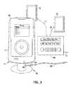
- FIG. 8is a schematic representation of a media system including a multi-function docking assembly of the invention, having a portable digital media storage and playback device docked and retained therein, and arranged in transmitting relationship to an external receiver having audio speakers attached thereto.
- FIG. 9is a pivotably adjustable ratchet adaptor, which is coupleable with a cigarette lighter power socket, e.g., a conventional 12 volt socket connected to the battery system and/or charging system of a motor vehicle, wherein the outer coupling end of the adaptor is engagable with the port on the rear face of the multi-function docking assembly, with the ratchet arm being pivotably adjustable to spatially position the portable digital media storage and playback device at a given orientation relative to a user.
- a cigarette lighter power sockete.g., a conventional 12 volt socket connected to the battery system and/or charging system of a motor vehicle
- the ratchet armbeing pivotably adjustable to spatially position the portable digital media storage and playback device at a given orientation relative to a user.
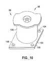
- FIG. 10is a short adaptor coupleable with the coupling structure on the rear face of the docking assembly of FIGS. 1-6 , wherein the adaptor includes a wall mounting plate, accommodating wall mounting of the multi-function docking assembly.
- FIG. 11is a desk mount device, in which the short adaptor of FIG. 10 may be reposed, to provide desktop access of a user to the portable digital media storage and playback device as reposed in the multi-function docking assembly coupled with the adaptor mounted on the desk mount article.
- FIG. 12is a front elevation view of a multi-function docking assembly according to another embodiment of the present invention.
- FIG. 13is a left-hand side view, in elevation, of the docking assembly of FIG. 12 .
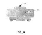
- FIG. 14is a bottom plan view of the docking assembly of FIGS. 12-13 .
- FIG. 15is a rear elevation view of the docking assembly of FIGS. 12-14 .
- FIG. 16is a right-hand side view, in elevation, of the assembly of FIGS. 12-15 .
- FIG. 17is a top plan view of the multi-function docking assembly of FIGS. 12-16 .
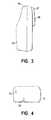
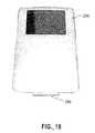
- FIG. 18is a perspective view of a portable digital media storage and playback device having a connector adapted for coupling with a Firewire® port or a USB port.
- FIG. 19is a schematic front elevation view of a multi-function docking assembly according to another embodiment of the invention, arranged for mounting therein of a portable digital media storage and playback device of the type shown in FIG. 18 .
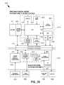
- FIG. 20is a block diagram showing the interconnection between various elements of a multi-function docking assembly and various elements of a portable digital media storage and playback device connected thereto, with each of the device and the assembly having an authentication element.
- FIG. 21is a functional block diagram for an authentication scheme that may be utilized by and between a multi-function docking assembly according to the present invention and a portable digital media storage and playback device.
- FIG. 22is a flowchart of a method for communicating a signal from a portable digital media storage and playback device to an external receiving device, the method including an authentication step.
- the present inventionprovides a multi-function docking assembly for a portable digital media storage and playback device that dramatically increases the utility of the basic portable digital media storage and playback (PDMSP) device.
- a docking assembly according to the present inventionpreferably provides device retention, wireless signal transmission, power supply and/or handling utility, and authentication utility to ensure that the docking assembly is interoperable with an associated PDMSP device.
- a signal transmitter utilized in a docking assemblypreferably comprises a radio frequency (RF) transmitter adapted to transmit at any of various RF frequencies a signal including media content played by the PDMSP device, enabling RF reception of media content signals that then can be received and played by an external receiving device.
- RF frequenciesin one embodiment include FM signals in a range of preferably from about 87.5 to about 108 MHz.
- Operable RF frequencies in another embodimentinclude a range from about 800 MHz to about 10 GHz.
- the wireless transmittermay transmit a signal compatible with a wireless network, such as an IEEE 802.16-compliant (WiMax) network, IEEE 802.11-complaint (Wi-Fi) network, an IEEE 802.15.1-compliant (Bluetooth) network, or similar or equivalent networks.
- a wireless networksuch as an IEEE 802.16-compliant (WiMax) network, IEEE 802.11-complaint (Wi-Fi) network, an IEEE 802.15.1-compliant (Bluetooth) network, or similar or equivalent networks.
- WiFiwireless fidelity
- Wireless signalsmay be intended for local-area or extended-area broadcast.
- a wireless receiver(not shown) may be provided, and preferably integrated with the wireless transmitter 549 to form a transceiver adapted for two-way network communication.
- a multi-function docking assemblyincluding a FM transmitter, an electrical circuit element for providing power supply and/or charging utility, and an authentication element may be deployed in an automobile or other vehicular environment, wherein the docking assembly is powered by a power adaptor plugged into a cigarette lighter socket of the vehicle.
- the FM transmitterthen transmits music signals originated by the PDMSP device to the FM receiver in the vehicle, enabling the acoustic system of the vehicle to be employed for broadcast of the music to the interior passenger compartment of the vehicle.
- a multi-function docking assemblymay as hereinafter described more fully comprise an AC charger enabling the battery of the PDMSP device to be recharged to a more fully charged state allowing its use period to be lengthened while on battery power.
- the multi-function docking assemblymay be provided in a kit including a base docking unit and various adaptor/charger/mount accessories, as hereinafter described.
- an iPod® PDMSP devicemay utilize a Firewire® (IEEE 1394) port for power connection purposes, other types of port and electrical connection means may be employed.
- Firewire®IEEE 1394
- more recently-released iPod® PDMSP devicesemploy 30-pin couplings.
- FIG. 1shows a front elevation view of a multi-function docking assembly 10 having a main body portion 12 including a back wall whose surface 14 together with side rails 18 and 20 define a cavity in which a PDMSP device is selectively reposable, received, and retained.
- Various componentsmay be integrated into the main body portion 12 .
- a connector adapted for connection with a PDMSP deviceis provide separately (e.g., connected by a cable) from a main body housing various components.
- the multi-function docking assemblyis provided with a male connector element 26 matably engagable with the headphone port of the PDMSP device, as well as a coupling 28 matably engagable with the Firewire® port of the PDMSP device.
- the coupling 28preferably comprises multiple (more preferably at least about ten, and still more preferably at least about thirty) discrete electrically conductive contact elements.
- a signal transmitteris disposed substantially within the body portion 12 of the multi-function docking assembly to transmit media content played through the PDMSP device to a range of RF (e.g., FM) frequencies.
- the signal transmittermay be of any suitable type, and operates to transmit media content to an external receiver disposed in signal receiving proximity to the multi-function docking assembly and PDMSP device docked therein.
- the signal transmittermay for example be provided having a tuning frequency in the FM band of 87.5 to 108.1 megahertz (MHz) and a transmission range of 4-6 feet or more.
- Stereo transmitters of such typeare readily commercially available, and are of appropriate size for incorporation in a multi-function docking assembly.
- a FM transmittermay simply transmit at a frequency fixed in the aforementioned 88-95 MHz band, or the transmitter may be tunable to select a specific frequency within such spectrum, preferably including at least one frequency generally in a range including about 88 MHz to about 108 MHz.
- an external FM receiverreceives the transmitted audio from the PDMSP device transmitted by the multi-function docking assembly, and the FM receiver (e.g., located in a user's automobile) is then able to receive (e.g., by tuning the FM receiver to the frequency used by the transmitter in the multi-function docking assembly), amplify, and reproduce via the vehicular sound system the audio content as audible sound in the automobile passenger cabin.
- the FM receivere.g., located in a user's automobile
- the interior of the body or housing of a multi-function docking assemblypreferably also includes circuitry and components for charging the battery of the PDMSP device, through the Firewire® port or other (e.g., USB) input port, as well as providing power to the PDMSP device when docked in the multi-function docking assembly.
- circuitry and componentsfor charging the battery of the PDMSP device, through the Firewire® port or other (e.g., USB) input port, as well as providing power to the PDMSP device when docked in the multi-function docking assembly.
- the multi-function docking assemblyhas on a lower portion 22 thereof indicator lights 30 and 32 , which are configured for indicating when the PDMSP device is charging or fully charged, and/or when the PDMSP device is “ON.”
- the multi-function docking assemblymay also be provided with an ON/OFF switch, for selectively actuating the PDMSP device, controlling the charging function of the multi-function docking assembly, etc.
- FIG. 2is a rear elevation view of a multi-function docking assembly, showing the back wall surface 34 , on which is provided a boss 37 forming a coupling cavity 36 including a power connector element 38 .
- the housing of the multi-function docking assemblymay be of a 2-piece construction, with mechanical fastener elements 40 , 42 , 44 and 46 serving to couple the respective parts of the assembly.
- Various parts of the multi-function docking assemblymay be removably coupled using these mechanical fasteners 40 , 42 , 44 , and 46 , or by any other appropriate means.
- the multi-function docking assemblymay be formed of a unitary molded material, having a port or opening therein for insertion and assembly of the interior components, including circuitry and components as described hereinabove.
- FIG. 3is a right-hand side elevation view of the multi-function docking assembly, showing the retention member 24 at the upper portion of the housing.
- FIG. 4is a bottom plan view of the multi-function docking assembly, including a further mechanical fastener 50 for retaining interior assembly elements of the assembly.
- FIG. 5is a top plan view of the multi-function docking assembly, showing the retention member 24 , which is selectively disengagable by thumb-actuatable release member 54 .
- FIG. 6is a left-hand side elevation view of the multi-function docking assembly, showing the symmetrical character of same relative to the view illustrated in FIG. 3 .
- FIG. 7illustrates the FM transmitter and power supply/charging assembly 10 having a PDMSP device 56 disposed in the cavity of the body 12 and communicatively coupled to the assembly 10 via the connector element 26 and coupling 28 .
- FIG. 8is a corresponding view of PDMSP device 56 mounted in the body 12 of the FM transmitter and power supply/charging assembly 10 .
- the multi-function docking assemblyis mounted on a pedestal 60 having an arm extending upwardly at the rear of the multi-function docking assembly and coupling with the power element 38 on boss 37 (see FIGS. 2 , 3 and 6 ).
- the pedestal 60is provided with an electrical coupling 62 accommodating power plug 64 connected to power cord 66 , providing power to the pedestal 60 for transmittal through contact 38 to the PDMSP device by element 28 , as shown in FIG. 1 .
- the corresponding signalis transmitted through coupling element 26 shown in FIG. 1 to the FM transmitter in the housing of the multi-function docking assembly, generating an FM signal that is transmitted to FM receiver 68 powered by power cord 70 .
- the FM receiver 68in turn is coupled by speaker wires 74 and 78 to speakers 72 and 76 , respectively.
- the audio content played by the PDMSP device 56is transmitted by the FM transmitter to FM receiver 68 and outputted as sound output at speakers 72 and 76 .
- the PDMSP devicecan be electrically charged to renew the battery power of the device, so that when undocked from the multi-function docking assembly, the PDMSP device may be outfitted with earphones and deployed in a personal listening arrangement.
- FIG. 8 embodimentis shown as including a table-type FM receiver, it will be recognized that the arrangement is illustrative only, and is adaptable to automotive or vehicular sound systems including an FM receiver or a receiver of another suitable type.
- the multi-function docking assembly as shown in FIGS. 1-6may be coupled with a power source in any suitable manner.
- FIG. 9shows a ratchet-type adaptor 80 including engagement structure 82 matable with the cavity 36 shown in FIG. 2 on the multi-function docking assembly.
- the coupling structure 82is at the face of tubular member 81 which is pivotably mounted on spindle 84 which is positionable by means of the manual wing-nut 86 , which is selectively manually tightenable or loosenable, to adjust the attitude of tubular member 81 relative to the main body 88 of the adaptor.
- the main body 88is joined to a plug end 90 featuring electrical contact elements 92 and 94 , for engagement of the plug end 90 with a corresponding socket, such as a cigarette lighter socket of a motor vehicle.
- a corresponding socketsuch as a cigarette lighter socket of a motor vehicle.
- FIG. 10shows another adaptor 96 having engagement structure 98 at the extremity of cylindrical member 100 mounted on plate number 102 .
- the engagement structure 98is engagable with the cavity 37 at the rear face of the multi-function docking assembly (see FIG. 2 ).
- the plate 102 shown in FIG. 10is provided with mounting openings 104 , 106 and 108 , for wall-attachment of the adaptor, using mounting screws, nails, etc.
- the adaptor shown in FIG. 10permits the multi-function docking assembly to be wall-mounted, whereby the PDMSP device may be selectively docked and undocked from the wall-mounted multi-function docking assembly.
- FIG. 11is a perspective view of a desk mount article 120 , in which the short adaptor 96 shown in FIG. 10 may be selectively reposed, or coupling with the desk mount article 120 joined to power cord 122 .
- the multi-function docking assembly as shown in FIGS. 1-6may thereby be coupled with the adaptor 96 of the desk mount article by engagement of the engagement structure with the cavity 37 and electrical coupling 38 as shown in FIG. 2 .
- FIG. 12is a front elevation view of an FM transmitter and power supply/charging assembly 200 , or multi-function docking assembly, according to another embodiment of the present invention.
- the multi-function docking assembly 200includes a main body portion 212 defining a cavity for selectively reposing the PDMSP device therein.
- the cavityis bounded by back wall 214 and side rails 218 and 220 .
- Extending into the cavityis a male coupling or connector 226 , which may serve to couple the multi-function docking assembly with the headphone jack of the PDMSP device, as well as a coupling 228 matably engagable with the Firewire® port of the PDMSP device.
- Such couplings 226 , 228engage PDMSP device when it is received by the docking assembly 200 .
- the docking assembly 200 and PDMSP devicemay be joined in a single step of depressing at least a portion of the PDMSP device into or against the body to simultaneously engage the couplings 226 , 228 .
- the cavity as shownis also bounded by laterally inwardly facing elements, which serve as inwardly extending tabs on the respective side rails, to assist in retaining the PDMSP device in position in the cavity during media content play, storage or charging of the player.
- an LED power indicator light 230On the upper portion 222 of the multi-function docking assembly 200 in the position shown, is provided an LED power indicator light 230 , and a Firewire® port adjustment switch 221 , which serves to laterally reposition the coupling 228 in the cavity, so that the coupling is placed in register with the Firewire® port of the PDMSP device.
- a retractable security shelf member 224is provided on the lower portion of the multi-function docking assembly 200 in the position illustrated in FIG. 12 .
- the shelf member 224can be selectively manually adjusted to a forward position to assist in retaining the PDMSP device in the cavity of the docking assembly, so that the PDMSP device is positionally fixtured in the cavity of the multi-function docking assembly during use or charging of the PDMSP device.
- FIG. 13is a left-hand side view, in elevation, of the multi-function docking assembly 200 of FIG. 12 , showing the boss 237 on the rear surface of the assembly and the protruding power connector element 238 .
- a headphone jack 219is provided on the side surface of the assembly, as shown, for selective use of the multi-function docking assembly in a headphones-engaged listening mode when a PDMSP device is mounted in the unit.
- FIG. 14is a bottom plan view of the multi-function docking assembly shown in FIG. 12 , showing the retractable security shelf 224 .
- the shelf memberincludes a ridged surface to facilitate engagement with the thumb or other digit of the user, in selectively extending the shelf forwardly to secure the PDMSP device in position, or alternatively to retract the shelf so that the PDMSP device can be removed from the multi-function docking assembly.
- FIG. 15is a rear elevation view of the multi-function docking assembly of FIG. 12 , showing the boss 237 on the back wall surface 234 .
- the boss 237forms a coupling cavity 236 including the power connector element 238 therein.
- the housing of the multi-function docking assembly of this embodimentcan be of two-piece (or more than two-piece) construction, wherein each of the front and back sections of the housing are secured to one another by means of mechanical fasteners 240 , 242 and 244 , as shown.
- the housing of the multi-function docking assemblymay alternatively be formed of single-piece construction, or otherwise formed and fabricated in a suitable manner facilitating fabrication of the assembly.
- FIG. 16is a right-hand side view, in elevation, of the assembly of FIG. 12 , showing the boss 237 on the back wall surface and the power connector element 238 protruding therefrom.
- the retractable security shelf 224is shown at the bottom of the assembly in the view illustrated, and the Firewire® port adjustment switch 221 is shown protruding from the upper end of the assembly.
- FIG. 17is a top plan view of the multi-function docking assembly shown in FIG. 12 , with the Firewire® port adjustment switch 221 protruding from the front surface of the main body portion 212 of the assembly.
- FIG. 18is a perspective view of a PDMSP device 256 having a connector 259 adapted for docking with a Firewire® port or a USB port.
- the PDMSP device 256 illustrated in FIG. 18is an iPod® PDMSP device, available from Apple Computer, Inc., Cupertino, Calif., although other PDMSP devices can be used with multi-function docking assemblies according to the present invention.
- FIG. 19is a schematic front elevation view of a multi-function docking assembly 300 according to another embodiment of the invention, arranged for mounting therein of a PDMSP device of the type shown in FIG. 18 .
- the multi-function docking assembly 300includes a housing 312 defining a cavity therein bounded by back wall surface 314 and the side rails 318 and 320 of the housing. At the bottom extremity of the cavity is positioned a dock connector 327 that mates with the connector 259 of the PDMSP device 256 (see FIG. 18 ).
- the multi-function docking assembly 300has on a lower portion of the housing, on a frontal surface thereof, a frequency indicator display 330 , which in the drawing indicates a frequency of 102.5 megahertz (MHz) being transmitted by the transmitter in the docking assembly.
- a tuning control 332which can be variously configured as a membrane switch, as a thumb-wheel control, or other control member that is selectively actuatable to increase or decrease the transmitter frequency, as desired.
- the FM transmitterhas selectively adjustable digital frequency tuning
- the frequency indicator displayis a digital display adapted to display the transmission frequency to the user.
- a power indicator 334which may comprise an LED or other suitable element indicating the power “ON” or “OFF” status of the assembly.
- an FM transmitter indicator element 336Adjacent to the power indicator 334 is an FM transmitter indicator element 336 which may likewise comprise an LED or other suitable element indicating the “ON” or “OFF” status of the FM transmitter disposed in the housing.
- the multi-function docking assembly 300 of FIG. 19is shown as coupled to a flexible 12-volt cigarette lighter adapter 350 , to enable the assembly to be powered from the electrical system of a vehicle, by plug-in of the adapter 350 into the cigarette lighter of the vehicle.
- the connected multi-function docking assembly 300then is situated to receive the PDMSP device in the cavity of the housing, and to be actuated to transmit audio from the PDMSP device to the sound system of the vehicle in which the multi-function docking assembly is mounted.
- the FM transmitter and power supply/charging assembly of the present inventionmay be widely varied in specific structure, while providing FM transmission ability to the PDMSP device docked therein, and concurrently providing charging capability to the PDMSP device battery, as well as power during docked usage of the PDMSP device.
- the various adaptors shown, as well as the associated mounting articles,may be provided as a kit together with the FM transmitter and power supply/charging assembly, to provide a package of alternative parts for varied deployment of the docked PDMSP device.
- a docking assembly and a PDMSP deviceeach include an authentication element, such as an integrated circuit, adapted to communicate with one another to execute an authentication scheme employed at least the first time that the accessory device is connected to the PDMSP device, with successful authentication being a prerequisite for the transfer of any substantive content or control signals between the PDMSP and the accessory device.
- an authentication elementsuch as an integrated circuit
- a challenge and response-based authentication schemeis employed for the authentication scheme.
- Examples of integrated circuitsthat may be used to provide or easily adapted to provide such functionality include: the Texas Instruments BQ26150-family of ICs (including models BQ26150DCKR and BQ26150DCKRG4) (Texas Instruments Inc., Dallas, Tex.); the Dallas Semiconductor/Maxim DS2703-family of ICs (including models DS2703U and DS2703U+)(Maxim Integrated Products, Sunnyvale, Calif.); and the Intersil ISL6296 family of ICs (Intersil Corp., Milpitas, Calif.).
- FIG. 20provides a block diagram of a preferred coupled combination 400 of a PDMSP device 410 and a multi-function docking assembly 450 adapted to provide authentication utility.
- the docking assembly 450includes at least one electrical interface coupling 451 that mates with a corresponding at least one electrical interface coupling 411 associated with the PDMSP device.
- the PDMSP deviceincludes a central processing unit or CPU 420 (such as a complex instruction set computer microcontroller) that interfaces with various other components.
- CPU 420such as a complex instruction set computer microcontroller
- User keys 426 or other input elementsmay be used to communicate user commands to the CPU 420 .
- a data storage element 425utilizes any of a rotating disc (hard drive or microdrive) and flash memory to store various media files in addition to other data files and/or executable programs.
- a digital signal processor or DSP 428which may be integrated into the CPU 420 if desired, may be used to execute post-processing algorithms like equalization and bass management on files to be output, either directly through the digital-to-audio converter or DAC 430 as a line level output, or through the DAC 430 and a headphone amplifier 432 as an amplified output with volume control.
- a data exchange element 434preferably including Universal Serial Bus (USB) or Firewire® (IEEE 1394) connectivity, may be used to transfer data to or from the data storage element 425 .
- An authorization element 435preferably including an integrated circuit, may be used to authenticate an accessory device such as a multi-function docking assembly 450 .
- a display element 424preferably including a high resolution LCD or LED display, may be provided to drive graphical user interface menus, play still images, and/or play video files.
- a battery 421is in electrical communication with a power management element 422 , which may provide DC-DC step-down conversion utility for various electronic elements of the PDMSP device, linear regulation utility for the audio amplifier 432 , DC-DC boost conversion utility for the display element 424 , synchronization boost conversion utility for the data exchange element 434 or other input/output elements, and charge regulation/AC charging utility for the battery 421 .
- the multi-function docking assembly 450includes one or more power supply/charging/conditioning elements 452 to receive power from an external power source 462 , condition the same for use by various elements within the docking assembly 452 , and/or conduct power to the PDMSP device 410 by way of the coupled interface couplings 451 , 411 .
- the power supplied to the PSMSP device from the external power source by way of the one or more power supply/charging/conditioning elements 452may be used to power the PDMSP device 410 and/or charge the battery 421 of the same.
- the docking assembly 450further includes an authorization element 455 such as described previously.
- the authorization element 455preferably comprises an integrated circuit and a memory, with the memory preferably including both a public memory for storing unencrypted communicable information and secret or encrypted information.
- the authorization element 455is preferably reprogrammable, such as by way of connection to a data exchange (e.g., USB or other) port 464 that may be linked to an appropriate device such as a personal computer or PDA to accomplish reprogramming functions if desired.
- a data exchangee.g., USB or other
- Such reprogramming utilitymay be desirable, for example, to enable use of the docking assembly 450 with new releases of PDMSP devices 410 having potentially new and different authentication data or authentication schemes as such new PDMSP devices may become available.
- the authorization element 455may be integrated into a central microprocessor associated with the docking assembly 450 .
- the multi-function docking assembly 450includes a signal transmitter 460 adapted to transmit at any of various, preferably RF and more preferably FM, frequencies a signal including media content received from the PDMSP device 410 .
- a display 454preferably comprising a digital frequency indicator display 454 is provided to display the transmission frequency of the signal transmitter 460 , with the transmission frequency subject to user adjustment via user keys 456 or an equivalent user input device.
- a dedicated antenna 461 in electrical communication with the signal transmitter 460may be optionally provided.
- any of various electrical elements associated with the docking assemblysuch as a power supply cord may be used to enhance the transmission of signals from the transmitter 460 .
- the docking assembly 450may further include a line level output connector 468 to communicate a media content signal to any of various auxiliary devices connectable to the docking assembly 450 .
- FIG. 21provides a functional block diagram for a basic challenge and response-based authentication scheme that may be utilized by and between a multi-function docking assembly 450 and a portable digital media storage and playback device 410 .
- the “host” or “challenger”e.g., authentication element 435 associated with the PDMSP device 410
- the “responder”e.g., authentication element 455 associated with the docking assembly 450
- a random challengemay consist of a number of bits of random data generated by the host.
- Each authentication element 435 , 455preferably includes a memory for storing certain authentication information, with the memory of at least the docking assembly authentication element 455 preferably being reprogrammable.
- the memory of each authentication element 435 , 455preferably includes both a private memory (e.g., for including unencrypted information and/or a secret key that is preferably not subject to transmission) and a public memory (e.g., for including encrypted information and/or a public key, unique device ID, or other less sensitive information).
- the responder 455uses stored information to produce a response string for transmission back to the host 435 .
- the host 435performs the same authentication transform using stored information, or some combination of stored information and information communicated by the responder (e.g., an encrypted key passed by the responder 455 ).
- the resultcompares the transform value computed by the host 435 against the response (transform value) obtained from the responder 455 .
- the hostauthenticates the responder and allows the PDMSP device and the accessory device to start operation and/or substantive communication. Otherwise, the authentication fails, and the authentication element (either alone or in with the aid of the CPU 420 ( FIG. 20 )) it may inhibit operation of the system 400 ( FIG. 20 ) and provide a warning signal to the user, e.g., through the display 424 ( FIG. 20 ).
- a challenge-and-response authentication schememay utilize cyclic redundancy check (CRC) in an authentication transform.
- CRCcyclic redundancy check
- Challenges and keys of various bit lengthsmay be used.
- a 32-bit random challenge and 96-bit secret IDare used in conjunction with a random polynomial and 16-bit seed value to generate a 16-bit CRC response.
- a unique CRC polynomial, CRC seed, and device ID valuemay be used in each device.
- Such valuesmay be stored as encrypted text in public memory and unencrypted (plain) text in private memory, such that only a host system can decrypt the polynomial, seed, and ID values using a stored secret key.
- the hostreads the encrypted device ID, polynomial, and seed values from public memory, decrypts these values using a secret key, and then generates a (e.g., 32-bit) random challenge.
- the random challengeis transmitted to the responder, which uses challenge information from the host along with the plain-text version of polynomial coefficients, seed, and device ID to calculate the authentication CRC value.
- the hostuses the polynomial coefficients, seed, and device ID that it decrypted, along with the random challenge that it sent to the responder to calculate the authentication CRC value.
- the responder authentication CRC valuemay be transmitted back to the host where the two authentication CRC values are compared, with a match serving to authenticate the responder and initiate system operation and/or substantive communication.
- a challenge-and-response authentication schememay utilize an iterative hashing algorithm such as the SHA-1/HMAC secure hash algorithm, which has been widely used for authentication of Internet transactions.
- the authentication methodis similar to a CRC-based scheme except it utilizes a different algorithm.
- the hostreads a (e.g., 128-bit) encrypted device ID from the public memory and decrypts those values using the secret key to yield plain-text information with root keys. Then it generates a (e.g., 160-bit) random challenge that is transmitted to the responder, which uses the plain-text version of the ID along with the random challenge to calculate an authentication digest value.
- the hostuses the decrypted ID and the same random challenge to calculate its own authentication digest value.
- the hostreads the authentication digest value from the responder and compares that value to its own authentication digest value. If a match is obtained, then the responder is authenticated and system operation and/or substantive communication may be initiated.
- an authentication elementemploys the Secure Hash Algorithm (SHA-1) specified in the Federal Information publication 180-1 and 180-2, and ISO/IEC 10118-3.
- An authentication IC embedded in the accessory deviceprocesses a host transmitted challenge using a stored secret key and unique ROM ID to produce a response word for transmission back to the host.
- the secret keyis securely stored on-chip and never transmitted between the battery and the host. If each of the secret key and the ROM ID includes 64 bits, the response may include 160 bits.
- FIG. 22provides a flowchart of one such method for transmitting a signal from a PDMSP to an external receiving device.
- the method 490includes multiple illustrative steps.
- a first step 491includes providing a PDMSP device.
- a second step 492includes providing a multi-function docking assembly as described herein (e.g., including a body adapted to receive and retain the PDMSP device, at least one electrical coupling associated with the body and adapted to engage the PDMSP device when the PDMSP device is received by the body, a transmitter connectable to the PDMSP device via the at least one electrical coupling, at least one electrical circuit element adapted to conduct power to the electrical coupling, and an authentication element adapted to provide an authentication signal to the PDMSP device.
- a third step 493includes joining the docking assembly and the PDMSP device in a single step of depressing at least a portion of the PDMSP device into or against he body to simultaneously engage the electrical coupling.
- a fourth step 494includes performing an authentication step including communicating an authentication signal between any of the authentication element and the PDMSP device.
- a fifth step 495includes wirelessly transmitting a signal including media content played by the PDMSP device. The fifth step is preferably only permitted when an appropriate match or handshake is established between the authentication element and the PDMSP device; otherwise, such functionality may be disabled or diminished by the PDMSP device.
- the authentication steppreferably further includes the performance of a challenge and response authentication scheme.
- an authentication operationmay involve multiple iterative steps to “unlock” various features or functions of a PDMSP device, such that multiple discrete tiers of functionality of the PDMSP device may be enabled or disabled depending on the result of an authentication operation between the PDMSP device and the multi-function docking assembly (or any other suitable accessory device not necessarily involving all the features of, or including features different from, multi-function docking assemblies as described herein).
- operation of the PDMSP device with a multi-function docking assembly or other accessorymay commence, but in a limited or restricted fashion, or in an unrestricted fashion, depending on the result of the authentication operation.
- Different levels or tiers of operation that may be unlocked, whether individually in combination, depending on the result of an authentication operationinclude (but are not limited to) the following examples:
- authentication elements and authentication methods according to the present inventionpermit not only “yes/no” threshold operability between a PDMSP device and an accessory device such as a multi-function docking assembly, but also permit discrete functions of a PDMSP device or between the PDMSP device and docked accessory to be enabled or disabled depending on the result of an authentication operation.
Landscapes
- Engineering & Computer Science (AREA)
- Theoretical Computer Science (AREA)
- Computer Hardware Design (AREA)
- Physics & Mathematics (AREA)
- General Engineering & Computer Science (AREA)
- General Physics & Mathematics (AREA)
- Computer Security & Cryptography (AREA)
- Human Computer Interaction (AREA)
- Software Systems (AREA)
- Charge And Discharge Circuits For Batteries Or The Like (AREA)
Abstract
Description
- a body adapted to receive and retain the portable digital media storage and playback device;
- at least one electrical coupling associated with the body and adapted to engage the portable digital media storage and playback device when the portable digital media storage and playback device is received by the body;
- a transmitter connectable with the portable digital media storage and playback device via the at least one electrical coupling and adapted to wirelessly transmit media content from the portable digital media storage and playback device to an external receiving device;
- at least one electrical circuit element adapted to conduct power from an external power source to the at least one electrical coupling; and
- an authentication element adapted to provide an authentication signal to the portable digital media storage and playback device.
- providing the above-described docking assembly;
- joining the docking assembly and the portable digital media storage and playback device in a single step of depressing at least a portion of the portable digital media storage and playback device into or against the body to simultaneously engage the at least one electrical coupling;
- performing an authentication step including communicating an authentication signal between the authentication element and the portable digital media storage and playback device; and
- wirelessly transmitting a signal including media content played by the portable digital media storage and playback device.
- a cavity-defining body adapted to receive and retain the portable digital media storage and playback device;
- at least one electrical coupling disposed in the cavity and adapted to engage the portable digital media storage and playback device when the portable digital media storage and playback device is received by the body;
- a transmitter connectable with the portable digital media storage and playback device via the at least one electrical coupling and adapted to wirelessly transmit media content from the portable digital media storage and playback device to an external receiving device;
- at least one electrical circuit element adapted to conduct power from an external power source through the at least one electrical coupling to the portable digital media storage and playback device; and
- an authentication element adapted to provide an authentication signal to the portable digital media storage and playback device.
- providing the above-described docking assembly;
- joining the docking assembly and the portable digital media storage and playback device in a single step of depressing at least a portion of the portable digital media storage and playback device into or against the body to simultaneously engage the at least one electrical coupling;
- performing an authentication step including communicating an authentication signal between the authentication element and the portable digital media storage and playback device; and
- wirelessly transmitting a signal including media content played by the portable digital media storage and playback device.
- providing a multi-function docking assembly comprising:
- a body adapted to receive and retain at least a portion of a portable digital media storage and playback device;
- at least one electrical coupling disposed in or on the cavity and adapted to engage the portable digital media storage and playback device when the portable digital media storage and playback device is received by the body;
- a transmitter connectable with the portable digital media storage and playback device via the at least one electrical coupling and adapted to wirelessly transmit media content from the portable digital media storage and playback device to an external receiving device;
- at least one electrical circuit element adapted to conduct power from an external power source to the at least one electrical coupling; and
- an authentication element adapted to provide an authentication signal to the portable digital media storage and playback device;
- joining the docking assembly and the portable digital media storage and playback device to engage the at least one electrical coupling;
- performing an authentication step including communicating an authentication signal between the authentication element and the portable digital media storage and playback device; and
- wirelessly transmitting a signal including media content played by the portable digital media storage and playback device.
- enabling powering or charging of a PDMSP device by a docking assembly;
- enabling full-quality/full bandwidth communication of digital media content from a PDMSP device to a docking assembly (e.g., through the electrical coupling);
- enabling downgraded-quality (e.g., limited bandwidth) communication of digital media content from the PDMSP device to the docking assembly (e.g., through the electrical coupling);
- enabling playback of protected digital media content by the PDMSP device, but only for a limited number of times;
- enabling digital media content (or only unprotected digital content) to be sent from a docking assembly to the PDMSP device (e.g., through the electrical coupling) to be stored therein;
- enabling command signals to be communicated from a docking assembly to the PDMSP device (e.g., through the electrical coupling); and
- enabling digital media content stored in the PDMSP device to be transmitted via a wireless transmitter.
Claims (54)
Priority Applications (1)
| Application Number | Priority Date | Filing Date | Title |
|---|---|---|---|
| US11/557,473US8010728B1 (en) | 2005-11-07 | 2006-11-07 | Multi-function docking assembly for portable digital media storage and playback device |
Applications Claiming Priority (2)
| Application Number | Priority Date | Filing Date | Title |
|---|---|---|---|
| US73405805P | 2005-11-07 | 2005-11-07 | |
| US11/557,473US8010728B1 (en) | 2005-11-07 | 2006-11-07 | Multi-function docking assembly for portable digital media storage and playback device |
Publications (1)
| Publication Number | Publication Date |
|---|---|
| US8010728B1true US8010728B1 (en) | 2011-08-30 |
Family
ID=44486378
Family Applications (1)
| Application Number | Title | Priority Date | Filing Date |
|---|---|---|---|
| US11/557,473Expired - Fee RelatedUS8010728B1 (en) | 2005-11-07 | 2006-11-07 | Multi-function docking assembly for portable digital media storage and playback device |
Country Status (1)
| Country | Link |
|---|---|
| US (1) | US8010728B1 (en) |
Cited By (16)
| Publication number | Priority date | Publication date | Assignee | Title |
|---|---|---|---|---|
| US20090254690A1 (en)* | 2007-06-08 | 2009-10-08 | Modu Ltd. | Communication card with standalone and master operational states |
| US20110099316A1 (en)* | 2009-10-28 | 2011-04-28 | Google Inc. | Dock-Specific Display Modes |
| US20110302347A1 (en)* | 2010-06-04 | 2011-12-08 | Apple Inc. | Class-Based Compatibility Testing and Notification |
| US20120196550A1 (en)* | 2011-02-01 | 2012-08-02 | I O Interconnect, Ltd. | Apparatus for vehicle and signal processing method |
| US20120271970A1 (en)* | 2011-04-20 | 2012-10-25 | Apple Inc. | Situational playback |
| US20130024592A1 (en)* | 2011-07-20 | 2013-01-24 | Samsung Electronics Co. Ltd. | Docking station for communication terminal |
| US20130111096A1 (en)* | 2011-10-26 | 2013-05-02 | Nai-Chien Chang | Docking device with a built-in network share module |
| US20130297844A1 (en)* | 2012-05-04 | 2013-11-07 | Jpmorgan Chase Bank, N.A. | System and Method for Mobile Device Docking Station |
| US20150212967A1 (en)* | 2014-01-30 | 2015-07-30 | Eric Jermaine Griffin | Wireless Communication Adaptor And Receiver Device With Integrated Speakers |
| US20150371030A1 (en)* | 2014-05-19 | 2015-12-24 | Lenovo (Singapore) Pte. Ltd. | Providing access to and enabling functionality of first device based on communication with second device |
| US20160239436A1 (en)* | 2006-01-24 | 2016-08-18 | Clevx, Llc | Data security system |
| US9781496B2 (en) | 2012-10-25 | 2017-10-03 | Milwaukee Electric Tool Corporation | Worksite audio device with wireless interface |
| US9820320B2 (en)* | 2015-12-09 | 2017-11-14 | Intel IP Corporation | Docking station and method to connect to a docking station |
| US9892628B2 (en) | 2014-10-14 | 2018-02-13 | Logitech Europe S.A. | Method of controlling an electronic device |
| US9891693B1 (en) | 2013-04-17 | 2018-02-13 | Western Digital Technologies, Inc. | Storage system comprising a communications port for charging an electronic device |
| US10476284B2 (en) | 2011-12-30 | 2019-11-12 | Makita Corporation | Battery system for a power tool, as well as battery holder therefor, charger, and charging system |
Citations (89)
| Publication number | Priority date | Publication date | Assignee | Title |
|---|---|---|---|---|
| JPH0374125U (en) | 1989-11-16 | 1991-07-25 | ||
| US5319716A (en) | 1991-09-17 | 1994-06-07 | Recoton Corporation | Wireless CD/automobile radio adapter |
| JPH06309854A (en) | 1993-04-27 | 1994-11-04 | Rohm Co Ltd | Car-mount adapter with sound signal transfer function |
| JPH0729981U (en) | 1993-11-04 | 1995-06-02 | 村田機械株式会社 | In-vehicle adapter for mobile phones |
| US5448757A (en) | 1990-04-28 | 1995-09-05 | Pioneer Electronic Corporation | Audio signal modulating system with pre-emphasis |
| WO1996032783A1 (en)* | 1995-04-11 | 1996-10-17 | Mold-Tech Plastics Limited Partnership | Interface for portable communications device |
| US5771441A (en) | 1996-04-10 | 1998-06-23 | Altstatt; John E. | Small, battery operated RF transmitter for portable audio devices for use with headphones with RF receiver |
| US5829993A (en)* | 1996-12-16 | 1998-11-03 | Formosa Electronic Industries Inc. | Charger with a replaceable electrical plug |
| US5839919A (en)* | 1997-02-06 | 1998-11-24 | E. Lead Electronic Co., Ltd. | In-car used mobile phone fixing seat assembly to which other electrical appliances are addible |
| US5860824A (en) | 1997-04-14 | 1999-01-19 | Fan; Eagle | Extension device for mounting in automobile cigarette lighter holder |
| US5970390A (en) | 1997-10-09 | 1999-10-19 | Sony Corporation | Transmitter and automobile audio apparatus using the same |
| WO1999065210A1 (en)* | 1998-06-10 | 1999-12-16 | Marcus Andersson | Holder for a mobile telephone |
| US6138041A (en)* | 1998-09-23 | 2000-10-24 | Ccm Cellular Connection Of Miami, Inc. | Device for safe use of a portable cellular telephone while driving |
| US6157163A (en) | 1999-09-28 | 2000-12-05 | Blackwood; Reginald S. | Automobile charging unit for a pager |
| JP3074125U (en) | 2000-06-16 | 2000-12-19 | 朝男 小林 | Transmitter with inverter |
| US6163711A (en) | 1997-12-01 | 2000-12-19 | Nokia Mobile Phones, Ltd | Method and apparatus for interfacing a mobile phone with an existing audio system |
| US6175926B1 (en) | 1998-05-08 | 2001-01-16 | Hewlett-Packard Company | Password protection for computer docking station |
| KR20010008949A (en) | 1999-07-06 | 2001-02-05 | 윤종용 | Portable audio player and the same method |
| JP2001093585A (en) | 1999-09-28 | 2001-04-06 | Sony Corp | Charging stand and charging system for charging electronic instrument mounted in charging stand |
| US6240297B1 (en) | 1997-12-04 | 2001-05-29 | Alcatel | Docking station for mobile telecommunication handset |
| US20010006336A1 (en) | 1999-12-30 | 2001-07-05 | Lg Electronics Inc. | Battery charger for cellular phone, having speaker |
| US6292440B1 (en) | 1998-11-02 | 2001-09-18 | Ids Corporation | MP3 car player |
| US6317497B1 (en) | 1999-05-12 | 2001-11-13 | Jack Ou | Toggle joint combination for extending a receptacle of automobile cigarette lighter and application thereof |
| US20010049566A1 (en) | 2000-05-12 | 2001-12-06 | Samsung Electronics Co., Ltd. | Apparatus and method for controlling audio output in a mobile terminal |
| JP2002007004A (en) | 2000-06-19 | 2002-01-11 | Aiwa Co Ltd | Communication terminal device |
| US6339699B1 (en)* | 1997-09-24 | 2002-01-15 | Harness System Technologies Research, Ltd. | Phone holder |
| KR20020010350A (en) | 2000-07-29 | 2002-02-04 | 이강엽 | Apparatus for FM transmit of portable MP3 player |
| KR20020014875A (en) | 2000-08-19 | 2002-02-27 | 윤종용 | Digital broadcasting receiver built-in MP3 player function |
| US20020032042A1 (en) | 2000-02-18 | 2002-03-14 | Poplawsky Ralph C. | Exporting controls to an external device connected to a portable phone system |
| US20020038432A1 (en) | 2000-09-27 | 2002-03-28 | Acer Communications And Multimedia Inc. | Automatic charging device via a universal serial bus and method of operating the same |
| US6381452B1 (en) | 1999-11-01 | 2002-04-30 | Ting-Kuei Tien | Multifunction new-type audio player structure |
| WO2002037499A1 (en) | 2000-10-30 | 2002-05-10 | Miroslaw Wrobel | Device for playing back mp3 files |
| US6396769B1 (en) | 1999-10-04 | 2002-05-28 | Rany Polany | System for housing a personal S.C.U.B.A diving audio system |
| US20020077834A1 (en) | 2000-12-15 | 2002-06-20 | Estevez Leonardo W. | Removable face plate compressed digital music player |
| JP2002178857A (en) | 2000-12-13 | 2002-06-26 | Car Mate Mfg Co Ltd | Transmitter device for vehicle |
| US20020086703A1 (en) | 2000-12-28 | 2002-07-04 | Brother International Corporation | Mobile computing device docking station |
| US20020086716A1 (en) | 1999-01-06 | 2002-07-04 | Priority Tech, Inc. | Hands-free mobile phone kit |
| KR20020054686A (en) | 2000-12-28 | 2002-07-08 | 구자홍 | Mobile phone having FM transmission module |
| US6420849B2 (en) | 2000-07-27 | 2002-07-16 | Koninklijke Philips Electronics N.V. | Power generating device having a form factor suitable for insertion into a player device |
| US6423892B1 (en) | 2001-01-29 | 2002-07-23 | Koninklijke Philips Electronics N.V. | Method, wireless MP3 player and system for downloading MP3 files from the internet |
| US20020098813A1 (en) | 2000-11-01 | 2002-07-25 | George Likourezos | Apparatus and method for generating and transmitting an RF modulated signal having a modulation frequency within the AM and/or FM band |
| US20020105861A1 (en) | 2000-12-29 | 2002-08-08 | Gateway, Inc. | Standalone MP3 recording station |
| US20020132651A1 (en) | 2001-03-16 | 2002-09-19 | Kohki Jinnouchi | Portable communication terminal charger system |
| US20020151327A1 (en) | 2000-12-22 | 2002-10-17 | David Levitt | Program selector and guide system and method |
| US20020173866A1 (en) | 2000-09-14 | 2002-11-21 | Andreas Dangberg | Digital mp3 audio device |
| US20030026439A1 (en) | 2000-08-08 | 2003-02-06 | Niles Part Co., Ltd. | Audio system for automobile and plug transmitter used in same |
| US20030036357A1 (en) | 2001-08-17 | 2003-02-20 | Intel Corporation | Apparatus and methods for finding and using available transmission frequencies |
| US6532152B1 (en) | 1998-11-16 | 2003-03-11 | Intermec Ip Corp. | Ruggedized hand held computer |
| US6573683B2 (en) | 2001-08-15 | 2003-06-03 | Wan Jiun Hsing Enterprises Co., Ltd. | Swivel-jointed voltage-stepping automobile charger |
| US20030114133A1 (en) | 2001-12-14 | 2003-06-19 | Ryan S. Enners | MP3 player for vehicles |
| US6591085B1 (en) | 2002-07-17 | 2003-07-08 | Netalog, Inc. | FM transmitter and power supply/charging assembly for MP3 player |
| US20030154355A1 (en) | 2002-01-24 | 2003-08-14 | Xtec, Incorporated | Methods and apparatus for providing a memory challenge and response |
| US6608399B2 (en) | 2000-10-17 | 2003-08-19 | Lear Corporation | Vehicle universal docking station and electronic feature modules |
| DE10217365C1 (en) | 2003-02-04 | 2003-08-28 | Kastriot Merlaku | Automobile audio system has car radio provided with insertion opening for portable mini audio device |
| US6631098B2 (en) | 2001-07-02 | 2003-10-07 | Prolific Technology Inc. | Dual-mode MP3 player |
| US20030194968A1 (en) | 2002-04-15 | 2003-10-16 | Young Steven Jay | System and method for local modulation and distribution of stored audio content |
| US20030236075A1 (en) | 2002-06-21 | 2003-12-25 | Johnson Timothy Michael | Wireless output input device player |
| US6671494B1 (en) | 1998-06-18 | 2003-12-30 | Competive Technologies, Inc. | Small, battery operated RF transmitter for portable audio devices for use with headphones with RF receiver |
| US6681120B1 (en) | 1997-03-26 | 2004-01-20 | Minerva Industries, Inc., | Mobile entertainment and communication device |
| US20040091124A1 (en) | 2002-11-08 | 2004-05-13 | Chua Hiap Chew | Audio devices |
| US20040107253A1 (en) | 1993-10-01 | 2004-06-03 | Collaboration Properties, Inc. | System for real-time communication between plural users |
| US6762585B2 (en)* | 2001-10-03 | 2004-07-13 | Sheng Hsin Liao | Combinational charger apparatus |
| US20040151327A1 (en) | 2002-12-11 | 2004-08-05 | Ira Marlow | Audio device integration system |
| US6781519B1 (en) | 2000-05-23 | 2004-08-24 | Alpine Electronics, Inc. | Method and vehicle system for remote-controlling vehicle audio system |
| US6788528B2 (en) | 2002-01-05 | 2004-09-07 | Hewlett-Packard Development Company, L.P. | HP jornada vehicle docking station/holder |
| US20040193900A1 (en) | 2000-03-17 | 2004-09-30 | Mark Nair | System, method and apparatus for controlling the dissemination of digital works |
| US20040224638A1 (en) | 2003-04-25 | 2004-11-11 | Apple Computer, Inc. | Media player system |
| US6836643B2 (en) | 2001-02-05 | 2004-12-28 | Moshe Shealtiel | Module specific interface for cellular phones |
| US20050047071A1 (en) | 2003-08-26 | 2005-03-03 | Bobby Tse Chun Hin | Wireless transmission interface and method |
| US20050062695A1 (en) | 2003-09-23 | 2005-03-24 | Eastman Kodak Company | Display device and system |
| US20050135790A1 (en) | 2003-12-23 | 2005-06-23 | Sandisk Corporation | Digital media player with resolution adjustment capabilities |
| US20050170744A1 (en) | 2004-01-30 | 2005-08-04 | Steven Smith | Toy with remote media source |
| US20050195848A1 (en) | 2004-02-09 | 2005-09-08 | Canon Europa Nv | Method and system for the initialization and validation of the setting up or transfer of a connection in a communications network, corresponding terminals and remote-control unit |
| US20050227773A1 (en) | 2003-09-24 | 2005-10-13 | Lu Priscilla M | Portable video storage and playback device |
| US6973477B1 (en) | 1995-05-19 | 2005-12-06 | Cyberfone Technologies, Inc. | System for securely communicating amongst client computer systems |
| US20060031617A1 (en) | 2002-11-15 | 2006-02-09 | Microsoft Corporation | Portable computing device-integrated appliance |
| US20060039263A1 (en) | 2004-08-20 | 2006-02-23 | Remy Trotabas | Audio system with removable digital media player |
| US20060052144A1 (en)* | 2004-09-08 | 2006-03-09 | Seil Oliver D | Holder, electrical supply, and RF transmitter unit for electronic devices |
| US7013164B2 (en) | 2004-03-24 | 2006-03-14 | Jow Tong Technology Co., Ltd. | FM transmitter and charger assembly for MP3 players with different sizes |
| US20060156415A1 (en)* | 2005-01-07 | 2006-07-13 | Rubinstein Jonathan J | Accessory authentication for electronic devices |
| US20060184978A1 (en) | 2005-02-16 | 2006-08-17 | Qwest Communications International Inc. | Mobile device base station for enhanced signal strength for on-demand media services |
| US20060274910A1 (en) | 2005-06-03 | 2006-12-07 | Altec Lansing Technologies, Inc. | Portable media reproduction system |
| US7187947B1 (en) | 2000-03-28 | 2007-03-06 | Affinity Labs, Llc | System and method for communicating selected information to an electronic device |
| US20070077784A1 (en) | 2005-08-01 | 2007-04-05 | Universal Electronics Inc. | System and method for accessing a user interface via a secondary device |
| US20070086724A1 (en) | 2002-07-17 | 2007-04-19 | Jeff Grady | Interface systems for portable digital media storage and playback devices |
| US20070124804A1 (en)* | 2005-11-28 | 2007-05-31 | Visteon Global Technologies, Inc. | System and method to provide for passive anti-theft dockable devices |
| US20070300155A1 (en) | 2004-04-27 | 2007-12-27 | Laefer Jay S | Method and system for controlling video selection and playback in a portable media player |
| US20080015717A1 (en) | 2006-03-03 | 2008-01-17 | Griffin Paul P Jr | Auxiliary power adapter having device controls |
| US20080025172A1 (en)* | 2004-04-27 | 2008-01-31 | Apple Inc. | Method and System For Allowing A Media Player To Transfer Digital Audio To An Accessory |
- 2006
- 2006-11-07USUS11/557,473patent/US8010728B1/ennot_activeExpired - Fee Related
Patent Citations (97)
| Publication number | Priority date | Publication date | Assignee | Title |
|---|---|---|---|---|
| JPH0374125U (en) | 1989-11-16 | 1991-07-25 | ||
| US5448757A (en) | 1990-04-28 | 1995-09-05 | Pioneer Electronic Corporation | Audio signal modulating system with pre-emphasis |
| US5319716A (en) | 1991-09-17 | 1994-06-07 | Recoton Corporation | Wireless CD/automobile radio adapter |
| JPH06309854A (en) | 1993-04-27 | 1994-11-04 | Rohm Co Ltd | Car-mount adapter with sound signal transfer function |
| US20040107253A1 (en) | 1993-10-01 | 2004-06-03 | Collaboration Properties, Inc. | System for real-time communication between plural users |
| JPH0729981U (en) | 1993-11-04 | 1995-06-02 | 村田機械株式会社 | In-vehicle adapter for mobile phones |
| JPH10507052A (en) | 1995-03-04 | 1998-07-07 | モルド−テック プラスティックス リミテッド パートナーシップ | External communication source for radio interface |
| US6052603A (en) | 1995-04-11 | 2000-04-18 | Mold-Tech Plastics Limited Partnership | System for interfacing a communication device with a radio for hands-free operation |
| WO1996032783A1 (en)* | 1995-04-11 | 1996-10-17 | Mold-Tech Plastics Limited Partnership | Interface for portable communications device |
| US6973477B1 (en) | 1995-05-19 | 2005-12-06 | Cyberfone Technologies, Inc. | System for securely communicating amongst client computer systems |
| US5771441A (en) | 1996-04-10 | 1998-06-23 | Altstatt; John E. | Small, battery operated RF transmitter for portable audio devices for use with headphones with RF receiver |
| US5829993A (en)* | 1996-12-16 | 1998-11-03 | Formosa Electronic Industries Inc. | Charger with a replaceable electrical plug |
| US5839919A (en)* | 1997-02-06 | 1998-11-24 | E. Lead Electronic Co., Ltd. | In-car used mobile phone fixing seat assembly to which other electrical appliances are addible |
| US6681120B1 (en) | 1997-03-26 | 2004-01-20 | Minerva Industries, Inc., | Mobile entertainment and communication device |
| US5860824A (en) | 1997-04-14 | 1999-01-19 | Fan; Eagle | Extension device for mounting in automobile cigarette lighter holder |
| US6339699B1 (en)* | 1997-09-24 | 2002-01-15 | Harness System Technologies Research, Ltd. | Phone holder |
| US5970390A (en) | 1997-10-09 | 1999-10-19 | Sony Corporation | Transmitter and automobile audio apparatus using the same |
| US6163711A (en) | 1997-12-01 | 2000-12-19 | Nokia Mobile Phones, Ltd | Method and apparatus for interfacing a mobile phone with an existing audio system |
| US6240297B1 (en) | 1997-12-04 | 2001-05-29 | Alcatel | Docking station for mobile telecommunication handset |
| US6175926B1 (en) | 1998-05-08 | 2001-01-16 | Hewlett-Packard Company | Password protection for computer docking station |
| WO1999065210A1 (en)* | 1998-06-10 | 1999-12-16 | Marcus Andersson | Holder for a mobile telephone |
| US6671494B1 (en) | 1998-06-18 | 2003-12-30 | Competive Technologies, Inc. | Small, battery operated RF transmitter for portable audio devices for use with headphones with RF receiver |
| US6138041A (en)* | 1998-09-23 | 2000-10-24 | Ccm Cellular Connection Of Miami, Inc. | Device for safe use of a portable cellular telephone while driving |
| US6292440B1 (en) | 1998-11-02 | 2001-09-18 | Ids Corporation | MP3 car player |
| US6532152B1 (en) | 1998-11-16 | 2003-03-11 | Intermec Ip Corp. | Ruggedized hand held computer |
| US20020086716A1 (en) | 1999-01-06 | 2002-07-04 | Priority Tech, Inc. | Hands-free mobile phone kit |
| US6317497B1 (en) | 1999-05-12 | 2001-11-13 | Jack Ou | Toggle joint combination for extending a receptacle of automobile cigarette lighter and application thereof |
| KR20010008949A (en) | 1999-07-06 | 2001-02-05 | 윤종용 | Portable audio player and the same method |
| JP2001093585A (en) | 1999-09-28 | 2001-04-06 | Sony Corp | Charging stand and charging system for charging electronic instrument mounted in charging stand |
| US6157163A (en) | 1999-09-28 | 2000-12-05 | Blackwood; Reginald S. | Automobile charging unit for a pager |
| US6396769B1 (en) | 1999-10-04 | 2002-05-28 | Rany Polany | System for housing a personal S.C.U.B.A diving audio system |
| US6381452B1 (en) | 1999-11-01 | 2002-04-30 | Ting-Kuei Tien | Multifunction new-type audio player structure |
| US20010006336A1 (en) | 1999-12-30 | 2001-07-05 | Lg Electronics Inc. | Battery charger for cellular phone, having speaker |
| US6509716B2 (en) | 1999-12-30 | 2003-01-21 | Lg Electronics Inc. | Battery charger for cellular phone, having speaker |
| US20020032042A1 (en) | 2000-02-18 | 2002-03-14 | Poplawsky Ralph C. | Exporting controls to an external device connected to a portable phone system |
| US20040193900A1 (en) | 2000-03-17 | 2004-09-30 | Mark Nair | System, method and apparatus for controlling the dissemination of digital works |
| US7187947B1 (en) | 2000-03-28 | 2007-03-06 | Affinity Labs, Llc | System and method for communicating selected information to an electronic device |
| US20010049566A1 (en) | 2000-05-12 | 2001-12-06 | Samsung Electronics Co., Ltd. | Apparatus and method for controlling audio output in a mobile terminal |
| US6781519B1 (en) | 2000-05-23 | 2004-08-24 | Alpine Electronics, Inc. | Method and vehicle system for remote-controlling vehicle audio system |
| JP3074125U (en) | 2000-06-16 | 2000-12-19 | 朝男 小林 | Transmitter with inverter |
| JP2002007004A (en) | 2000-06-19 | 2002-01-11 | Aiwa Co Ltd | Communication terminal device |
| US6420849B2 (en) | 2000-07-27 | 2002-07-16 | Koninklijke Philips Electronics N.V. | Power generating device having a form factor suitable for insertion into a player device |
| KR20020010350A (en) | 2000-07-29 | 2002-02-04 | 이강엽 | Apparatus for FM transmit of portable MP3 player |
| US20030026439A1 (en) | 2000-08-08 | 2003-02-06 | Niles Part Co., Ltd. | Audio system for automobile and plug transmitter used in same |
| US20050049009A1 (en) | 2000-08-08 | 2005-03-03 | Niles Parts Co. Ltd. | Audio system for automobile and plug transmitter used in same |
| KR20020014875A (en) | 2000-08-19 | 2002-02-27 | 윤종용 | Digital broadcasting receiver built-in MP3 player function |
| US20020173866A1 (en) | 2000-09-14 | 2002-11-21 | Andreas Dangberg | Digital mp3 audio device |
| US20020038432A1 (en) | 2000-09-27 | 2002-03-28 | Acer Communications And Multimedia Inc. | Automatic charging device via a universal serial bus and method of operating the same |
| US6798173B2 (en) | 2000-09-27 | 2004-09-28 | Benq Corporation | Automatic charging device via a universal serial bus and method of operating the same |
| US6608399B2 (en) | 2000-10-17 | 2003-08-19 | Lear Corporation | Vehicle universal docking station and electronic feature modules |
| WO2002037499A1 (en) | 2000-10-30 | 2002-05-10 | Miroslaw Wrobel | Device for playing back mp3 files |
| US20020098813A1 (en) | 2000-11-01 | 2002-07-25 | George Likourezos | Apparatus and method for generating and transmitting an RF modulated signal having a modulation frequency within the AM and/or FM band |
| JP2002178857A (en) | 2000-12-13 | 2002-06-26 | Car Mate Mfg Co Ltd | Transmitter device for vehicle |
| US20020077834A1 (en) | 2000-12-15 | 2002-06-20 | Estevez Leonardo W. | Removable face plate compressed digital music player |
| US20020151327A1 (en) | 2000-12-22 | 2002-10-17 | David Levitt | Program selector and guide system and method |
| US20020086703A1 (en) | 2000-12-28 | 2002-07-04 | Brother International Corporation | Mobile computing device docking station |
| KR20020054686A (en) | 2000-12-28 | 2002-07-08 | 구자홍 | Mobile phone having FM transmission module |
| US20020105861A1 (en) | 2000-12-29 | 2002-08-08 | Gateway, Inc. | Standalone MP3 recording station |
| US6423892B1 (en) | 2001-01-29 | 2002-07-23 | Koninklijke Philips Electronics N.V. | Method, wireless MP3 player and system for downloading MP3 files from the internet |
| US6836643B2 (en) | 2001-02-05 | 2004-12-28 | Moshe Shealtiel | Module specific interface for cellular phones |
| US20020132651A1 (en) | 2001-03-16 | 2002-09-19 | Kohki Jinnouchi | Portable communication terminal charger system |
| US6631098B2 (en) | 2001-07-02 | 2003-10-07 | Prolific Technology Inc. | Dual-mode MP3 player |
| US6573683B2 (en) | 2001-08-15 | 2003-06-03 | Wan Jiun Hsing Enterprises Co., Ltd. | Swivel-jointed voltage-stepping automobile charger |
| US20030036357A1 (en) | 2001-08-17 | 2003-02-20 | Intel Corporation | Apparatus and methods for finding and using available transmission frequencies |
| US6762585B2 (en)* | 2001-10-03 | 2004-07-13 | Sheng Hsin Liao | Combinational charger apparatus |
| US20030114133A1 (en) | 2001-12-14 | 2003-06-19 | Ryan S. Enners | MP3 player for vehicles |
| US6788528B2 (en) | 2002-01-05 | 2004-09-07 | Hewlett-Packard Development Company, L.P. | HP jornada vehicle docking station/holder |
| US20030154355A1 (en) | 2002-01-24 | 2003-08-14 | Xtec, Incorporated | Methods and apparatus for providing a memory challenge and response |
| US20030194968A1 (en) | 2002-04-15 | 2003-10-16 | Young Steven Jay | System and method for local modulation and distribution of stored audio content |
| US6782239B2 (en) | 2002-06-21 | 2004-08-24 | Neuros Audio L.L.C. | Wireless output input device player |
| US20030236075A1 (en) | 2002-06-21 | 2003-12-25 | Johnson Timothy Michael | Wireless output input device player |
| US20070086724A1 (en) | 2002-07-17 | 2007-04-19 | Jeff Grady | Interface systems for portable digital media storage and playback devices |
| US20070114974A1 (en) | 2002-07-17 | 2007-05-24 | Jeff Grady | Fm transmitter and power supply / charging assembly for mp3 player |
| US6591085B1 (en) | 2002-07-17 | 2003-07-08 | Netalog, Inc. | FM transmitter and power supply/charging assembly for MP3 player |
| US7280802B2 (en) | 2002-07-17 | 2007-10-09 | Netalog, Inc. | FM transmitter and power supply/charging assembly for MP3 player |
| US20040091124A1 (en) | 2002-11-08 | 2004-05-13 | Chua Hiap Chew | Audio devices |
| US20060031617A1 (en) | 2002-11-15 | 2006-02-09 | Microsoft Corporation | Portable computing device-integrated appliance |
| US20040151327A1 (en) | 2002-12-11 | 2004-08-05 | Ira Marlow | Audio device integration system |
| DE10217365C1 (en) | 2003-02-04 | 2003-08-28 | Kastriot Merlaku | Automobile audio system has car radio provided with insertion opening for portable mini audio device |
| US20040224638A1 (en) | 2003-04-25 | 2004-11-11 | Apple Computer, Inc. | Media player system |
| US20050047071A1 (en) | 2003-08-26 | 2005-03-03 | Bobby Tse Chun Hin | Wireless transmission interface and method |
| US20050062695A1 (en) | 2003-09-23 | 2005-03-24 | Eastman Kodak Company | Display device and system |
| US20050227773A1 (en) | 2003-09-24 | 2005-10-13 | Lu Priscilla M | Portable video storage and playback device |
| US20050135790A1 (en) | 2003-12-23 | 2005-06-23 | Sandisk Corporation | Digital media player with resolution adjustment capabilities |
| US20050170744A1 (en) | 2004-01-30 | 2005-08-04 | Steven Smith | Toy with remote media source |
| US20050195848A1 (en) | 2004-02-09 | 2005-09-08 | Canon Europa Nv | Method and system for the initialization and validation of the setting up or transfer of a connection in a communications network, corresponding terminals and remote-control unit |
| US7013164B2 (en) | 2004-03-24 | 2006-03-14 | Jow Tong Technology Co., Ltd. | FM transmitter and charger assembly for MP3 players with different sizes |
| US20080025172A1 (en)* | 2004-04-27 | 2008-01-31 | Apple Inc. | Method and System For Allowing A Media Player To Transfer Digital Audio To An Accessory |
| US20070300155A1 (en) | 2004-04-27 | 2007-12-27 | Laefer Jay S | Method and system for controlling video selection and playback in a portable media player |
| US20060039263A1 (en) | 2004-08-20 | 2006-02-23 | Remy Trotabas | Audio system with removable digital media player |
| US20060052144A1 (en)* | 2004-09-08 | 2006-03-09 | Seil Oliver D | Holder, electrical supply, and RF transmitter unit for electronic devices |
| US20060156415A1 (en)* | 2005-01-07 | 2006-07-13 | Rubinstein Jonathan J | Accessory authentication for electronic devices |
| US20060184978A1 (en) | 2005-02-16 | 2006-08-17 | Qwest Communications International Inc. | Mobile device base station for enhanced signal strength for on-demand media services |
| US20060274910A1 (en) | 2005-06-03 | 2006-12-07 | Altec Lansing Technologies, Inc. | Portable media reproduction system |
| US20070077784A1 (en) | 2005-08-01 | 2007-04-05 | Universal Electronics Inc. | System and method for accessing a user interface via a secondary device |
| US20070124804A1 (en)* | 2005-11-28 | 2007-05-31 | Visteon Global Technologies, Inc. | System and method to provide for passive anti-theft dockable devices |
| US20080015717A1 (en) | 2006-03-03 | 2008-01-17 | Griffin Paul P Jr | Auxiliary power adapter having device controls |
Non-Patent Citations (29)
| Title |
|---|
| "Read-only memory"; Wikipedia, the Free Encyclopedia; Revision date Nov. 6, 2005; all pages.* |
| Application Note 190-Challenge and Response with 1-Wire SHA devices, Found online Mar. 28, 2007 at http://www.maxim-ic.com/appnotes.cfm/appnote-number/190, Mar. 12, 2002, Publisher: Maxim Integrated Products. |
| Arkon Resources, Inc., Arkon Multimedia PDA Mounting Solutions for use with Compaq iPAQ Pocket PC, Found online Jan. 11, 2007 at http://web.archive.org/web/20020310082543/www.arkon.com/expansions.html, Mar. 10, 2002. |
| Arkon Resources, Inc., Arkon Resources, Inc.-Multimedia PDA Mounts, Found online Jan. 11, 2007 at http://web.archive.org/web/20010813012145/www.arkon.com/multimedia.html, Aug. 13, 2001. |
| Arkon Resources, Inc., Arkon Resources, Inc.-SoundFeeder Audio Adapters, Found online Jan. 11, 2007 at http://web.archive.org/web/20010813021714/www.arkon.com/sf.html, Aug. 13, 2001. |
| Arkon Resources, Inc., CD mounting kist (sic) by Arkon Resources, Found online Jan. 11, 2007 at http://web.archive.org/web/19991005210543/arkon.com/cd.html, Oct. 5, 1999. |
| Arkon Resources, Inc., Portable CD Player Mounting Kits by Arkon Resources, Found online Jan. 11, 2007 at http://web.archive.org/web/20001019004111/www.arkon.com/cd.html, Oct. 19, 2000. |
| Arkon Resources, Inc., SF120 SoundFeeder Wireless Audio Adapter Arkon Resources, Inc., Found online Jan. 11, 2007 at http://web.archive.org/web/20010820131530/www.arkon.com/SF120.htm, Aug. 20, 2001. |
| Arkon Resources, Inc., SF121 SoundFeeder FM Stereo Transmitter, Found online Jan. 11, 2007 at http://web.archive.org/web/20010804135107/www.arkon.com/SF121.htm, Aug. 4, 2001. |
| Arkon Resources, Inc., SF145 CD-Mount Portable CD Mount by Arkon Resources, Inc., Found online Jan. 11, 2007 at http://web.archive.org/web/20001029113500/www.arkon.com/SF145.htm, Oct. 29, 2000. |
| Arkon Resources, Inc., SF340 CD-Mount Portable CD Mount by Arkon Resources, Inc., Found online Jan. 11, 2007 at http://web.archive.org/web/20001208183400/www.arkon.com/SF340.htm, Dec. 8, 2000. |
| Arkon Resources, Inc., SF342 CD-Mount Portable CD Mount by Arkon Resources, Inc., Found online Jan. 11, 2007 at http://web.archive.org/web/200010029124413/www.arkon.com/SF342.htm, Oct. 29, 2000. |
| Arkon Resources, Inc., Universal Multimedia mounts for pocket PC handheld computers, Consumer Electronics Show 2001, Jan. 2001, pp. #16444. |
| Di Jasio, Lucio, Using KEELOQ to Validate Subsystem Compatibility-AN827, Application Notes-found online Mar. 28, 2007 at http://ww1.microchip.com/downloads/en/AppNotes/00827a.pdf, 2002, Publisher: Microchip Technology Inc. |
| Dr. Bott, LLC, Dr. Botts LLC iPod Universal Connection Kit with FM Transmitter, Found online Jan. 11, 2007 at http://www.drbott.com/prod/db.lasso?code=0142-IPCK, 1999. |
| DS2703-SHA-1 Battery Pack Authentication IC, Found online Mar. 28, 2007 at http://datasheets.maxim-ic.com/en/ds/DS2703.pdf, 2007, Publisher: Maxim Integrated Products. |
| Evangelista, Benny, Dial M for music, San Francisco Chronicle-found online at http://www.sfgate.com/cgi-bin/article.cgi?file=/chronicle/archive/2000/11/01/BU105818.DTL, Nov. 1, 2000. |
| Federal Communications Commission, Grant of Equipment Authorization-FCC Identifier:ME2-SF345-SF340-Grantee: Arkon Resources, Inc., Found online Jan. 11, 2007 at http://gullfoss2.fcc.gov/prod.oet/cf/eas/reports/Eas731GrantForm.cfm?mode=COPY&Req..., Feb. 23, 1996. |
| Free On-Line Dictionary of Computing; "ROM & PROM"; Free On-Line Dictionary of Computing; May 9, 1995; 2 pages.* |
| Microsoft Press; "Computer Dictionary"; Microsoft Press; Second Edition; 1994; pp. 321 and 342.* |
| Priority Tech Inc., Priority Tech Products-Platinum Series; Hands-Free Kits, Found on-line on Jul. 19, 2006 at http://web.archive.org.web/20010805114853/www.priorityusa.com/newproducts-fullbands.html, 1999, Publisher: Priority Tech, Inc. |
| Priority Tech Inc., Voice Magic Plus, Found on-line Jun. 21, 2006 at http://www.gadgetcentral.com/voicecell-intro.html, Mar. 30, 2000. |
| Roth, Aaron, Deposition in Netalog v. Griffin Technology, Inc. litigation re U.S. Patent No. 6,591,085 in M.D.N.C. Case 1:04-CV 00850, pp. 1-8, 10-17, 19-28, 30-41, 49-72, 84-91, 95-98 & Ex. C, E, F, Q, R, S, T, U, V, W, 160, Oct. 27, 2005. |
| Smith, Tony, Sprint PCS to launch mobile MP3 scheme, The Register-found online at http://www.theregister.co.uk/2000/11/01/sprint-pcs-to-launch-mobile/, Nov. 1, 2000. |
| Vega, Michael, Complete battery-pack design for one- or two-cell portable applications, Analog Applications Journal-found online Mar. 28, 2007 at http://focus.ti.com/lit/an/slyt248/slyt248.pdf, 2006, pp. 14-16, vol. 3Q, Publisher: Texas Instruments, Inc. |
| Wagner, Samuel C., Arkon's Multimedia PDA Mount, Found online Aug. 11, 2006 at http://web.archive.org/web/20010803155949/www.pocketpcpower.net/PDAMount.htm, Aug. 3, 2001. |
| Wearden, Graeme, Virgin rolls out world's first MP3 phone, Tech news on ZDNet-found online at http://news.zdnet.com/2100-9595-22-523423.html, Aug. 28, 2000. |
| Williams, Martyn, Sony squeezes MP3 player into cell phone, PC World.com-found online at http://archives.cnn.com/3000/TECH/computing/12/12/mp3.cell.phone.idg/index.html, Dec. 12, 2000. |
| World's first MP3 phone, Popular Mechanics-found online at http://www.popularmechanics.com/technology/upgrade/1279751.html, Oct. 1, 2000. |
Cited By (27)
| Publication number | Priority date | Publication date | Assignee | Title |
|---|---|---|---|---|
| US20160239436A1 (en)* | 2006-01-24 | 2016-08-18 | Clevx, Llc | Data security system |
| US10146706B2 (en)* | 2006-01-24 | 2018-12-04 | Clevx, Llc | Data security system |
| US20090254690A1 (en)* | 2007-06-08 | 2009-10-08 | Modu Ltd. | Communication card with standalone and master operational states |
| US8260999B2 (en) | 2009-10-28 | 2012-09-04 | Google Inc. | Wireless communication with a dock |
| US20120023463A1 (en)* | 2009-10-28 | 2012-01-26 | Google Inc. | Dock-specific display modes |
| US8250278B2 (en)* | 2009-10-28 | 2012-08-21 | Google Inc. | Dock-specific display modes |
| US8250277B2 (en)* | 2009-10-28 | 2012-08-21 | Google Inc. | Dock-specific display modes |
| US8260998B2 (en) | 2009-10-28 | 2012-09-04 | Google Inc. | Wireless communication with a dock |
| US20110131358A1 (en)* | 2009-10-28 | 2011-06-02 | Google Inc. | Wireless Communication with a Dock |
| US11768081B2 (en) | 2009-10-28 | 2023-09-26 | Google Llc | Social messaging user interface |
| US20110099316A1 (en)* | 2009-10-28 | 2011-04-28 | Google Inc. | Dock-Specific Display Modes |
| US20110302347A1 (en)* | 2010-06-04 | 2011-12-08 | Apple Inc. | Class-Based Compatibility Testing and Notification |
| US8347014B2 (en)* | 2010-06-04 | 2013-01-01 | Apple Inc. | Class-based compatibility testing and notification |
| US20120196550A1 (en)* | 2011-02-01 | 2012-08-02 | I O Interconnect, Ltd. | Apparatus for vehicle and signal processing method |
| US20120271970A1 (en)* | 2011-04-20 | 2012-10-25 | Apple Inc. | Situational playback |
| US20130024592A1 (en)* | 2011-07-20 | 2013-01-24 | Samsung Electronics Co. Ltd. | Docking station for communication terminal |
| US20130111096A1 (en)* | 2011-10-26 | 2013-05-02 | Nai-Chien Chang | Docking device with a built-in network share module |
| US10476284B2 (en) | 2011-12-30 | 2019-11-12 | Makita Corporation | Battery system for a power tool, as well as battery holder therefor, charger, and charging system |
| US9442526B2 (en)* | 2012-05-04 | 2016-09-13 | JPMorgan Chase, Bank, N.A. | System and method for mobile device docking station |
| US20130297844A1 (en)* | 2012-05-04 | 2013-11-07 | Jpmorgan Chase Bank, N.A. | System and Method for Mobile Device Docking Station |
| US9781496B2 (en) | 2012-10-25 | 2017-10-03 | Milwaukee Electric Tool Corporation | Worksite audio device with wireless interface |
| US9891693B1 (en) | 2013-04-17 | 2018-02-13 | Western Digital Technologies, Inc. | Storage system comprising a communications port for charging an electronic device |
| US20150212967A1 (en)* | 2014-01-30 | 2015-07-30 | Eric Jermaine Griffin | Wireless Communication Adaptor And Receiver Device With Integrated Speakers |
| US20150371030A1 (en)* | 2014-05-19 | 2015-12-24 | Lenovo (Singapore) Pte. Ltd. | Providing access to and enabling functionality of first device based on communication with second device |
| US10306443B2 (en) | 2014-05-19 | 2019-05-28 | Lenovo (Singapore) Pte. Ltd. | Providing access to and enabling functionality of first device based on communication with second device |
| US9892628B2 (en) | 2014-10-14 | 2018-02-13 | Logitech Europe S.A. | Method of controlling an electronic device |
| US9820320B2 (en)* | 2015-12-09 | 2017-11-14 | Intel IP Corporation | Docking station and method to connect to a docking station |
Similar Documents
| Publication | Publication Date | Title |
|---|---|---|
| US8010728B1 (en) | Multi-function docking assembly for portable digital media storage and playback device | |
| US7280802B2 (en) | FM transmitter and power supply/charging assembly for MP3 player | |
| US7949810B2 (en) | Techniques for transferring data between a media player and an accessory having a tuner | |
| US20050014536A1 (en) | Modular adaptor assembly for personal digital appliance | |
| US7583495B2 (en) | Portable device docking station | |
| US7272420B2 (en) | Mobile device interface and adaptation system | |
| US20050151422A1 (en) | Universal serial bus connector in a vehicle | |
| US8359372B2 (en) | Automatic transfer of information through physical docking of devices | |
| US7826318B2 (en) | Method and system for allowing a media player to transfer digital audio to an accessory | |
| US9918039B2 (en) | Interface systems for portable digital media storage and playback devices | |
| US7338328B2 (en) | Cigarette lighter adapter device that interfaces with an external device via a port interface | |
| US8036609B2 (en) | FM transmitter for an MP player | |
| US20070086724A1 (en) | Interface systems for portable digital media storage and playback devices | |
| US20040162029A1 (en) | Audio player assembly comprising an MP3 player | |
| US20090304217A1 (en) | Apparatus and method for using a portable media unit | |
| US20080049479A1 (en) | Combined modulator and inverter | |
| WO2004008649A1 (en) | Modular adaptor assembly for personal digital appliance | |
| US20070155440A1 (en) | FM Transmitter for an MP3 Player | |
| US9363590B2 (en) | Playback device | |
| US10070225B1 (en) | Vehicle entertainment system | |
| US8738737B2 (en) | Portable media player for recording and playback of streamed digital content | |
| JP2005539469A5 (en) | ||
| US20050054400A1 (en) | Wireless local area network vehicular adapter | |
| KR200418764Y1 (en) | Wireless sound transmitter | |
| US8705756B1 (en) | Distributed audio system |
Legal Events
| Date | Code | Title | Description |
|---|---|---|---|
| AS | Assignment | Owner name:SUNTRUST BANK, AS ADMINISTRATIVE AGENT, GEORGIA Free format text:SECURITY AGREEMENT;ASSIGNOR:NETALOG, INC.;REEL/FRAME:018515/0349 Effective date:20061113 | |
| AS | Assignment | Owner name:NETALOG, INC., SOUTH CAROLINA Free format text:ASSIGNMENT OF ASSIGNORS INTEREST;ASSIGNORS:GRADY, JEFF;GUSTAFSON, VINCENT K.;SIGNING DATES FROM 20061108 TO 20061114;REEL/FRAME:018607/0946 | |
| AS | Assignment | Owner name:MONROE CAPITAL ADVISORS, LLC, ILLINOIS Free format text:SECURITY AGREEMENT;ASSIGNOR:NETALOG, INC.;REEL/FRAME:018837/0029 Effective date:20070119 | |
| AS | Assignment | Owner name:NETALOG, INC., NORTH CAROLINA Free format text:RELEASE BY SECURED PARTY;ASSIGNOR:MONROE CAPITAL ADVISORS, LLC;REEL/FRAME:019323/0565 Effective date:20070502 | |
| AS | Assignment | Owner name:NETALOG, INC., NORTH CAROLINA Free format text:RELEASE BY SECURED PARTY;ASSIGNOR:SUNTRUST BANK, AS ADMINISTRATIVE AGENT;REEL/FRAME:019466/0783 Effective date:20070509 | |
| AS | Assignment | Owner name:PHILIPS ELECTRONICS NORTH AMERICA, CORPORATION, MA Free format text:MERGER;ASSIGNOR:NETALOG, INC.;REEL/FRAME:025775/0220 Effective date:20081218 | |
| STCF | Information on status: patent grant | Free format text:PATENTED CASE | |
| FPAY | Fee payment | Year of fee payment:4 | |
| FEPP | Fee payment procedure | Free format text:MAINTENANCE FEE REMINDER MAILED (ORIGINAL EVENT CODE: REM.); ENTITY STATUS OF PATENT OWNER: LARGE ENTITY | |
| LAPS | Lapse for failure to pay maintenance fees | Free format text:PATENT EXPIRED FOR FAILURE TO PAY MAINTENANCE FEES (ORIGINAL EVENT CODE: EXP.); ENTITY STATUS OF PATENT OWNER: LARGE ENTITY | |
| STCH | Information on status: patent discontinuation | Free format text:PATENT EXPIRED DUE TO NONPAYMENT OF MAINTENANCE FEES UNDER 37 CFR 1.362 | |
| FP | Lapsed due to failure to pay maintenance fee | Effective date:20190830 |