US8010061B2 - Combining multimedia signaling and wireless network signaling on a common communication medium - Google Patents
Combining multimedia signaling and wireless network signaling on a common communication mediumDownload PDFInfo
- Publication number
- US8010061B2 US8010061B2US10/329,119US32911902AUS8010061B2US 8010061 B2US8010061 B2US 8010061B2US 32911902 AUS32911902 AUS 32911902AUS 8010061 B2US8010061 B2US 8010061B2
- Authority
- US
- United States
- Prior art keywords
- signal
- port
- wireless networking
- communication medium
- coupled
- Prior art date
- Legal status (The legal status is an assumption and is not a legal conclusion. Google has not performed a legal analysis and makes no representation as to the accuracy of the status listed.)
- Expired - Fee Related, expires
Links
- 238000004891communicationMethods0.000titleclaimsabstractdescription42
- 230000011664signalingEffects0.000titleclaimsabstractdescription17
- 230000006855networkingEffects0.000claimsabstractdescription63
- 230000005540biological transmissionEffects0.000claimsabstractdescription20
- 238000000034methodMethods0.000claimsdescription12
- 230000003466anti-cipated effectEffects0.000claimsdescription5
- 238000012986modificationMethods0.000description5
- 230000004048modificationEffects0.000description5
- 239000003990capacitorSubstances0.000description4
- 238000002955isolationMethods0.000description4
- 238000012546transferMethods0.000description4
- 230000000903blocking effectEffects0.000description3
- 238000013461designMethods0.000description3
- 238000010586diagramMethods0.000description3
- 230000003287optical effectEffects0.000description3
- 238000012545processingMethods0.000description3
- 239000000047productSubstances0.000description3
- 238000013459approachMethods0.000description2
- 230000008901benefitEffects0.000description2
- 230000008878couplingEffects0.000description2
- 238000010168coupling processMethods0.000description2
- 238000005859coupling reactionMethods0.000description2
- 239000000463materialSubstances0.000description2
- 239000013307optical fiberSubstances0.000description2
- 230000005855radiationEffects0.000description2
- 230000008054signal transmissionEffects0.000description2
- 230000008859changeEffects0.000description1
- 230000000694effectsEffects0.000description1
- 238000003780insertionMethods0.000description1
- 230000037431insertionEffects0.000description1
- 230000000644propagated effectEffects0.000description1
- 238000005070samplingMethods0.000description1
- 239000013589supplementSubstances0.000description1
Images


Classifications
- H—ELECTRICITY
- H04—ELECTRIC COMMUNICATION TECHNIQUE
- H04H—BROADCAST COMMUNICATION
- H04H20/00—Arrangements for broadcast or for distribution combined with broadcast
- H04H20/53—Arrangements specially adapted for specific applications, e.g. for traffic information or for mobile receivers
- H04H20/61—Arrangements specially adapted for specific applications, e.g. for traffic information or for mobile receivers for local area broadcast, e.g. instore broadcast
- H04H20/63—Arrangements specially adapted for specific applications, e.g. for traffic information or for mobile receivers for local area broadcast, e.g. instore broadcast to plural spots in a confined site, e.g. MATV [Master Antenna Television]
- H—ELECTRICITY
- H04—ELECTRIC COMMUNICATION TECHNIQUE
- H04H—BROADCAST COMMUNICATION
- H04H20/00—Arrangements for broadcast or for distribution combined with broadcast
- H04H20/65—Arrangements characterised by transmission systems for broadcast
- H04H20/76—Wired systems
- H04H20/77—Wired systems using carrier waves
- H04H20/78—CATV [Community Antenna Television] systems
- H04H20/79—CATV [Community Antenna Television] systems using downlink of the CATV systems, e.g. audio broadcast via CATV network
- H—ELECTRICITY
- H04—ELECTRIC COMMUNICATION TECHNIQUE
- H04N—PICTORIAL COMMUNICATION, e.g. TELEVISION
- H04N7/00—Television systems
- H04N7/10—Adaptations for transmission by electrical cable
- H04N7/106—Adaptations for transmission by electrical cable for domestic distribution
- H—ELECTRICITY
- H04—ELECTRIC COMMUNICATION TECHNIQUE
- H04B—TRANSMISSION
- H04B7/00—Radio transmission systems, i.e. using radiation field
- H04B7/02—Diversity systems; Multi-antenna system, i.e. transmission or reception using multiple antennas
- H04B7/04—Diversity systems; Multi-antenna system, i.e. transmission or reception using multiple antennas using two or more spaced independent antennas
- H04B7/08—Diversity systems; Multi-antenna system, i.e. transmission or reception using multiple antennas using two or more spaced independent antennas at the receiving station
- H04B7/0802—Diversity systems; Multi-antenna system, i.e. transmission or reception using multiple antennas using two or more spaced independent antennas at the receiving station using antenna selection
- H04B7/0805—Diversity systems; Multi-antenna system, i.e. transmission or reception using multiple antennas using two or more spaced independent antennas at the receiving station using antenna selection with single receiver and antenna switching
- H04B7/0814—Diversity systems; Multi-antenna system, i.e. transmission or reception using multiple antennas using two or more spaced independent antennas at the receiving station using antenna selection with single receiver and antenna switching based on current reception conditions, e.g. switching to different antenna when signal level is below threshold
Definitions
- the present inventionrelates generally to wireless communication systems, and more particularly relates to combining community antenna television (CATV) or other multimedia signaling and wireless network signaling on a cable or other communication medium.
- CATVcommunity antenna television
- the full-service access network (FSAN) standardallows a service provider to supply communication services to a building, including, for example, voice, video and data services, via an optical fiber.
- the FSAN standardis set forth, for example, in International Telecommunication Union-Telecommunication (ITU-T) Recommendation G.983.1, entitled Broadband Optical Access Systems Based on Passive Optical Networks ( PON ), October 1998, and amendments made thereto, which are incorporated herein by reference.
- ITU-TInternational Telecommunication Union-Telecommunication
- PONPassive Optical Networks
- a device located external to the buildinggenerally converts the optical signals carried over the optical fiber to standard voice, data and CATV signals.
- Most buildings todayare already equipped with coaxial cable and/or other wiring.
- the location of the external deviceis typically not suitable for radio frequency (RE) transmission of 802.11 signals into the building. This may be due, for instance, to the materials constituting the walls of the building, the proximity of the point of use inside the building, which may be referred to as a station, to the exterior access point, etc.
- REradio frequency
- the IEEE 802.11 standardaddresses medium access control over a wireless local area network (WLAN).
- the IEEE 802.11 standardis set forth in the document IEEE Std. 802.11, entitled Supplement to IEEE Standard for Information Technology - Telecommunications and Information Exchange Between Systems - Local Metropolitan Area Networks - Specific Requirements - Part 11: Wireless LAN Medium Access Control ( MAC ) and Physical Layer ( PHY ) Specifications, 1999 Edition, which is incorporated herein by reference. Additional extensions relating to the 802.11 standard, including IEEE Std. 802.11a, entitled High Speed Physical Layer in the 5 GHz Band , November 1999, IEEE Std. 802.11b, entitled Higher Speed Physical Layer ( PHY ) Extension in the 2.4 GHz Band , February 2000, and IEEE Std.
- 802.11gentitled Further Higher Data Rate Extension in the 2.4 GHz Band , September 2000, are also incorporated herein by reference.
- two separate physical cablesare employed to transfer CATV signals and wireless networking signals to a television and WLAN device, respectively, inside the building.
- CATV signals and wireless networking signalsare also incorporated herein by reference.
- WLAN deviceConventionally, two separate physical cables are employed to transfer CATV signals and wireless networking signals to a television and WLAN device, respectively, inside the building.
- there is a considerable cost disadvantage to this approachprimarily due to the requirement of installing additional wiring at the building site to support the wireless networking services.
- the present inventionin an illustrative embodiment, provides techniques for utilizing existing communication media, such as coaxial cabling, at a given location as a conduit for conveying at least multimedia signals (e.g., CATV signals) and wireless networking signals (e.g., 802.11a, 802.11b and 802.11g signals, etc.), thereby eliminating the need for additional wiring to support WLAN or alternative wireless communication services at the location.
- multimedia signalse.g., CATV signals
- wireless networking signalse.g., 802.11a, 802.11b and 802.11g signals, etc.
- apparatus for combining at least multimedia signaling (e.g., CATV signals) and wireless network signaling for transmission over the same communication mediumincludes a first port for receiving a multimedia signal, a second port for receiving a wireless networking signal, and a third port being couplable to the communication medium.
- the apparatusis configured for generating a combined signal at the third port, the combined signal including at least a portion of the multimedia signal and at least a portion of the wireless networking signal.
- wireless networking signalsmay be conveyed over the same communication medium as is used for multimedia signals.
- the apparatusfurther comprises a multiplexer including a first input coupled to an output of the first port, a second input coupled to an output of the second port, and an output coupled to an input of the third port.
- the multiplexeris operative: (i) to receive the multimedia signal from the first port; (ii) to receive the wireless networking signal from the second port; and (iii) to generate the combined output signal at the third port.
- FIG. 1is a block diagram illustrating an exemplary system for combining multimedia signaling and wireless network signaling on a common communication medium, in accordance with one aspect of the invention.
- FIG. 2is a block diagram illustrating an exemplary combiner circuit for use in the system of FIG. 1 , in accordance with the invention.
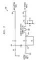
- FIG. 3is a schematic diagram illustrating an exemplary diversity switch for use in the system of FIG. 1 , in accordance with the invention.
- the present inventionwill be described herein in the context of an illustrative IEEE 802.11 compliant wireless communication system used, for example, in an FSAN environment. It should be appreciated, however, that the present invention is not limited to this or any particular wireless communication system and/or environment. Rather, the invention is more generally applicable to techniques for advantageously combining multimedia (e.g., CATV) signaling and wireless network signaling on a common communication medium (e.g., coaxial cable), thereby making use of existing wiring which may be present at a particular location to provide wireless networking services (e.g., WLAN) to the location. In this manner, the need for installing separate wiring at the location to support the additional wireless networking services can be eliminated.
- multimediae.g., CATV
- wireless network signalinge.g., coaxial cable
- the techniques of the invention described hereinmay be applied to essentially any information transmission system under which the electrical characteristics of the existing communication medium provide a suitable capacity for transmission of the wireless networking signals.
- the inventioncan also be used with other standards, as well as in non-standard systems.
- 802.11 signals, and alternative wireless networking signalsradiated outside a building, for example, near FSAN compliant customer premises equipment (CPE)
- CPEcustomer premises equipment
- FIG. 1depicts an exemplary system 100 in which the methodologies of the present invention may be implemented, in accordance with one aspect of the invention.
- the exemplary system 100comprises a combiner circuit 106 which includes a first input for receiving multimedia signals from a CATV receiver 102 , and at least a second input for receiving wireless networking signals from, for instance, an IEEE 802.11 compliant radio 104 (e.g., an access point).
- the combiner circuit 106may reside, for example, in a CPE device 116 exterior to the building.
- Combiner circuit 106preferably generates an output signal which operatively integrates the multimedia signals and the wireless networking signals for transmission over a single communication channel, which may comprise, for example, a cable 108 coupled to an output of the combiner circuit 106 , as will be described in further detail below.
- the CATV receiver 102 and the 802.11 radio 104both of which may reside in the CPE device 116 and are couplable to the combiner circuit 106 , may comprise conventional circuitry known to those skilled in the art. Accordingly, a detailed description of these components will not be presented herein.
- Cable 108may comprise a standard 50-ohm or 75-ohm coaxial cable (e.g., RG-58U), as is typically used for residential CATV wiring.
- cable 108may comprise wiring, such as, but not limited to, 300-ohm twin lead, twisted pair, etc.
- cable 108is routed at least partially throughout the interior of the building for connecting CATV equipment, such as, but not limited to, a television (TV) receiver, video cassette recorder (VCR), etc., to the CATV receiver 102 .
- CATV equipmentsuch as, but not limited to, a television (TV) receiver, video cassette recorder (VCR), etc.
- the inventionin at least one aspect, takes advantage of the existing wiring that may be present at a particular location to provide wireless networking, and/or additional services, to a desired location.
- cable 108is utilized, in essence, as an extension of the 802.11 radio 104 antenna, thereby increasing the operational range of the 802.11 radio.
- a first filter circuit 114may be coupled (e.g., in series) between the CATV equipment and the cable 108 to extract only those signals in the desired frequency band.
- the filter circuit 114may comprise a bandpass filter that is configurable to substantially attenuate signals having frequency components below and above the desired frequency range specified for conventional CATV operation, for example, below about 50 MHz, which effectively blocks any direct current (DC) signals that may produce an undesirable DC offset in the TV receiver, and above about 900 MHz, which substantially blocks any undesirable high frequency noise components which may be present in the signal. Modifications to filter 114 may be made and are contemplated by the invention so as to configure filter 114 for use with multimedia signals in an alternative frequency range other than CATV, as will be understood by those skilled in the art.
- filter circuit 114may instead comprise multiple filter stages coupled (e.g., in series) with one another and configurable to obtain a desired transfer characteristic. For instance, a bandpass transfer characteristic can be obtained from a combination of one or more low pass filters and one or more high pass filters coupled in series with the signal path, as will be understood by those skilled in the art.
- filter circuit 114may comprise one or more low pass filters configurable to produce a transfer characteristic having a cutoff frequency above a highest anticipated CATV signal frequency component.
- a wireless networking antennasuch as, for example, an IEEE 802.11 antenna, located inside the building and coupled to the cable 108 , is preferably used to radiate the wireless networking signals throughout the building for communication with one or more IEEE 802.11 compliant wireless devices (e.g., stations) inside the building.
- Wireless networking signalsare preferably transmitted using carrier frequencies substantially different from that used for CATV signaling (e.g., above about 900 MHz).
- IEEE 802.11b and IEEE 802.11g standardswhich govern most present WLAN communications, typically specify a carrier frequency of about 2.4 gigahertz (GHz).
- GHzgigahertz
- the IEEE 802.11a standardgoverns WLAN communications in the 5 GHz band.
- Wireless network communications using alternative frequency bands outside the multimedia frequency range of operationare similarly contemplated by the invention, with or without modifications to the components comprising exemplary system 100 .
- such wireless networking signalsmay be more easily discriminated from the multimedia signals existing in the combined signal transmitted over cable 108 .
- exemplary system 100may include a second filter circuit 110 coupled in series between the 802.11 antenna and the cable 108 .
- Second filter circuit 110may comprise one or more high pass filters configurable for substantially attenuating signals having frequency components below a predetermined value, for example, about 2.4 GHz, which essentially blocks any CATV or DC signals which may be present in the integrated signal generated by the combiner circuit 106 .
- Alternative circuitry for separating the CATV signals and the wireless networking signals from the integrated signal transmitted over the cable 108may also be employed, in accordance with the invention.
- second filter 110may be made and are contemplated by the invention so as to configure the filter 110 for use with wireless networking signals in an alternative frequency range other than 2.4 GHz (e.g., 5 GHz), as will be understood by those skilled in the art.
- alternative frequency rangeother than 2.4 GHz (e.g., 5 GHz), as will be understood by those skilled in the art.
- the exemplary system 100may optionally include an antenna diversity switch 112 coupled in series between an output of the second filter 110 and the 802.11 antenna.
- the antenna diversity switch 112can be used to eliminate nulls caused by multipath effects, and may be used where multiple antennas are employed for wireless network signaling.
- 802.11 WLAN systemsemploying multiple antennas, such as, for example, a MAIN antenna and an AUX antenna, one of the antennas is generally used for transmission, and a digital signal processor (DSP), or alternative processing device (e.g., controller, microprocessor, central processing unit (CPU), etc.) selects which of the two antennas to use for reception, based at least in part on the signal strength of a signal received from each antenna.
- DSPdigital signal processor
- CPUcentral processing unit
- the strength of a signal received by one antennamay be superior to the strength of the signal received by another antenna, due to its orientation and/or other characteristics, and therefore is the desirable one to use.
- antenna diversitymay be accomplished by measuring the signal strength associated with one antenna, and then quickly switching to another antenna and measuring the signal strength associated with that antenna. Assuming the signal strength does change quickly with time, the antenna having the greater signal strength will be employed for reception until the next sampling period.
- a direct current (DC) offsetis preferably driven over the cable 108 on which the modulated CATV and wireless networking signals ride. Since this DC offset is essentially only used by the diversity switch 112 , the offset is preferably removed, such as, for example, by filters 110 , 114 , before being presented to either a CATV or wireless networking device coupled to the cable.
- DCdirect current
- FIG. 2depicts an exemplary multiplexer circuit 200 in which at least a portion of the combiner circuit 106 may be implemented, in accordance with one aspect of the invention.
- the exemplary multiplexer circuit 200includes a first input 201 for receiving a CATV signal and a second input 203 for receiving an IEEE 802.11 compliant signal.
- the exemplary multiplexer circuit 200further includes an output 205 for conveying an output signal comprising at least a portion of the input CATV signal and at least a portion of the input 802.11 signal. This output may be coupled to the cable 108 shown in FIG. 1 .
- the exemplary multiplexer circuit 200comprises an amplifier 208 , such as, for example, an operational amplifier including an inverting input ( ⁇ ) at node 210 , a non-inverting input (+), and an output coupled to the output 205 of the circuit 200 .
- the amplifier 208in combination with resistors R A , R B and R C , is coupled in a voltage adder-multiplier arrangement, so as to form a summing junction at node 210 .
- resistor R Cis connected in a feedback arrangement, with one end of resistor R C coupled to the output 205 of the amplifier 208 and the other end of the resistor coupled to the inverting input of the amplifier at node 210 .
- Resistor R Ais coupled in series between the inverting input of amplifier 208 and the CATV input 201 .
- resistor R Bcoupled between the inverting input of amplifier 208 and the 802.11 input 203 .
- the non-inverting input of the amplifier 208is preferably coupled to the negative voltage supply of circuit 200 , which may be ground.
- Resistors R A , R B and R Cin addition to providing selective control of the individual gains of the CATV and 802.11 signal paths, respectively, further provide isolation between the two signal paths, and between the output 205 and a given input 201 , 203 of the circuit 200 .
- the amount of isolationwill depend, at least in part, on the resistance values selected for resistors R A , R B and R C . In the exemplary multiplexer circuit 200 , an acceptable amount of isolation may be achieved when resistors R A , R B R C are chosen to have values greater than, for instance, about 1000 ohms.
- K 1R C R A ,
- K 2R C R B , where V OUT is the voltage at the output 205 of the amplifier, V 212 and V 214 are the voltages at nodes 212 and 214 , respectively, K 1 is the gain through the CATV signal path, and K 2 is the gain through the 802.11 signal path.
- resistors R A and R Care each 2000 ohms and resistor R B is 1000 ohms.
- the gain K 1 through the CATV signal pathwill be about 1 and the gain K 2 through the 802.11 signal path will be about 2.
- the output voltage V OUTcan then be determined as ⁇ (V 212 +2V 214 ).
- the output voltagewill essentially comprise the input CATV signal and twice the input 802.11 signal.
- the exemplary multiplexer circuit 200is configurable for summing virtually any desired proportions of the input CATV and 802.11 signals.
- the impedance of the 802.11 transmission lineis first preferably matched to an output impedance associated with the existing cable ( 108 in FIG. 1 ) coupled to output 205 , which is used to convey the CATV signals (e.g., 75-ohm coaxial cable). This may be performed, for example, by an impedance matching circuit 206 coupled in series between the 802.11 input 203 and resistor R B at node 214 as shown.
- an impedance matching circuitmay be placed in series between the CATV input 201 and resistor R A at node 212 , in order to match the impedance of the CATV transmission line to the output impedance, assuming an impedance mismatch exists between the CATV transmission line and the cable ( 108 in FIG. 1 ).
- impedance matching circuitrymay be employed in both the CATV and the 802.11 signal paths for individually matching the impedances of the corresponding CATV and 802.11 transmission lines to the output transmission line impedance, in accordance with the invention.
- impedance matching circuit 206may comprise a simple passive inductive-capacitive (LC) network (not shown) operatively configured so that a reflection coefficient between a source (i.e., input) and load (i.e., output) of the circuit is substantially zero.
- LC impedance matching networksinclude, for example, Pi-networks, T-networks, etc., as are well known in the art.
- Alternative impedance matching circuitrymay be similarly utilized, as will be understood by those skilled in the art.
- a more detailed discussion on impedance matching networks suitable for use with the present inventionmay be found, for example, in the text Pieter L. D. Abrie, “Design of Impedance—Matching Networks for Radio-Frequency and Microwave Amplifiers,” Artech House Microwave Library , August 1985, which is incorporated herein by reference.
- the exemplary multiplexer circuit 200may comprise a first filter circuit 202 , which may be a low pass filter, coupled in series with the CATV signal path, such as, for example, between the CATV input 201 and resistor R A at node 212 .
- the filter circuit 202is preferably configured so as to substantially attenuate undesirable signals (e.g., high frequency noise, etc.) which may be present in the CATV signal.
- filter circuit 202may be configured to have a cutoff frequency of about 890 MHz, preferably allowing the filter circuit 202 to pass the highest anticipated CATV signal frequency substantially unattenuated, but substantially blocking signals having frequencies beyond the typical CATV operating range.
- a high pass filter(not shown), configured so as to substantially attenuate signals below a predetermined frequency (e.g., about 50 MHz, representing the lowest anticipated CATV signal frequency), may be coupled in series between the CATV input 201 and an input of filter 202 .
- filter circuit 202may comprise a bandpass filter, or a combination of one or more low pass and high pass filter stages, as previously described in connection with filter circuit 114 ( FIG. 1 ).
- the exemplary multiplexer circuit 200may comprise a second filter circuit 204 , which may be a high pass filter, coupled in series with the 802.11 signal path, such as, for example, between the 802.11 input 203 and an input of the impedance matching circuit 206 .
- the filter circuit 204is preferably configured so as to substantially attenuate undesirable signals (e.g., CATV signals, noise, etc.) which may be present in the 802.11 signal.
- Filter circuit 204may be similar to filter circuit 110 previously described.
- FIG. 3illustrates an exemplary circuit 300 in which the antenna diversity switch ( 112 in FIG. 1 ) may be implemented, in accordance with one aspect of the invention.
- the exemplary antenna diversity switch circuit 300includes a first port (Port 1 ) 302 which is couplable, directly or indirectly, to the antenna cable ( 108 in FIG. 1 ).
- Circuit 300further includes a second port (Port 2 ) 304 , which may be coupled to a MAIN antenna, and at least a third port (Port 3 ) 306 , which may be coupled to an AUX antenna.
- an 802.11 radioe.g., access point
- one of the antennas(e.g., MAIN antenna) is used for transmission, and a DSP, or alternative processing device, operatively selects which of the multiple antennas (e.g., MAIN or AUX antennas) to use for reception based, at least in part, on a comparison of signal strengths of the received signal from one or more of the antennas.
- a DSPor alternative processing device
- the exemplary circuit 300comprises RF PIN diodes D 1 and D 2 , operatively connected to enable the transmission of signals from port 302 to port 304 , while substantially blocking the transmission of signals from port 302 to port 306 .
- an anode of diode D 1is connected to port 302 at node 312 and a cathode of diode D 1 is connected to node 310 .
- An anode of diode D 2is connected to node 316 and a cathode of diode D 2 is coupled to the negative voltage supply, which may be ground.
- PIN diodesare typically employed in RF applications due, at least in part, to their very low forward resistance (e.g., less than about 1 ohm at 100 MHz), thereby providing low insertion loss, and very low capacitance (e.g., less than 0.3 pF at 100 MHz), thereby providing high isolation.
- a bypass capacitor C 4is connected in parallel across diode D 2 (i.e., between node 416 and ground).
- Coupling capacitors C 1 and C 3are connected in series between port 304 and node 310 , and between port 306 and node 316 , respectively.
- a load resistor R 1is connected between node 310 and ground.
- Coupling capacitor C 2is preferably connected in series between port 302 and a first end of a quarter wavelength stub 308 at node 314 .
- Resistor R 2is connected in parallel across capacitor C 2 (i.e., between node 312 and node 314 ).
- a second end of stub 308is coupled to node 316 .
- the stub 308is preferably tuned to be one quarter wavelength at a frequency of about 2.45 GHz, the desired operating frequency of the circuit 300 .
- a stub length of about three centimeters (cm)may be employed in exemplary circuit 300 .
- Table 1illustrates exemplary values which may be used for the components of circuit 300 , in accordance with a preferred embodiment of the invention.
- the values BAR 63 and BAR 80 for diodes D 1 and D 2represent preferred manufacturer part numbers (e.g., Infineon, Siemens, etc.).
- the values listed in Table 1may be suitable for use in a 2.4 GHz frequency band, the circuit may also be employed in alternative frequency bands (e.g., in a 5 GHz frequency band), with or without modification to the circuit 300 and/or component values specified.
- the cable 108preferably conveys the 802.11 compliant signal to an antenna within the building at a given location. This antenna then radiates the 802.11 signal to compatible stations (mobile or fixed) inside the building.
- at least a portion of the cable 108 itselfmay be used as a distributed antenna system to radiate the 802.11 signals, thereby eliminating the need for a separate antenna.
- RF signalspropagate along a wire as a surface-guided wave at low attenuation. As the surface wave propagates along the wire, it leaks radiation. The amount of RF leakage generally increases as the frequency of the signal increases.
- standard CATV cabling inside a buildingwhich is typically designed to carry signals having frequencies up to about 1 GHz, can also serve to radiate, at least somewhat, wireless networking signals (e.g., 802.11) transmitting at about 2.4 GHz or higher.
- leaky coaxremoves the shielding from portions of the coaxial cable inside the building in selected areas so as to provide RF coverage in unusually shaped environments that otherwise do not provide adequate coverage from a point source.
- Other commercially available productsinclude, for example, RadWire II, a trademark of Rubytron, which replaces radiating coaxial feeders, coaxial cable, individual antennas, etc., with a single-wire surface-wave transmission line. In either of these products, the primary objective is to utilize the cable itself as a distributed antenna system for radiating the wireless networking signals being conveyed through the cable.
Landscapes
- Engineering & Computer Science (AREA)
- Signal Processing (AREA)
- Multimedia (AREA)
- Input Circuits Of Receivers And Coupling Of Receivers And Audio Equipment (AREA)
- Two-Way Televisions, Distribution Of Moving Picture Or The Like (AREA)
Abstract
Description
VOUT=−(K1V212+K2V214),
where VOUTis the voltage at the
| TABLE 1 | |||
| Reference Designation | Value | ||
| C1, C2, C3, C4 | 8 picofarad (pF) | ||
| R1, R2 | 1000 ohms | ||
| D1 | BAR63 | ||
| D2 | BAR80 | ||
Claims (23)
Priority Applications (1)
| Application Number | Priority Date | Filing Date | Title |
|---|---|---|---|
| US10/329,119US8010061B2 (en) | 2002-12-24 | 2002-12-24 | Combining multimedia signaling and wireless network signaling on a common communication medium |
Applications Claiming Priority (1)
| Application Number | Priority Date | Filing Date | Title |
|---|---|---|---|
| US10/329,119US8010061B2 (en) | 2002-12-24 | 2002-12-24 | Combining multimedia signaling and wireless network signaling on a common communication medium |
Publications (2)
| Publication Number | Publication Date |
|---|---|
| US20040123322A1 US20040123322A1 (en) | 2004-06-24 |
| US8010061B2true US8010061B2 (en) | 2011-08-30 |
Family
ID=32594671
Family Applications (1)
| Application Number | Title | Priority Date | Filing Date |
|---|---|---|---|
| US10/329,119Expired - Fee RelatedUS8010061B2 (en) | 2002-12-24 | 2002-12-24 | Combining multimedia signaling and wireless network signaling on a common communication medium |
Country Status (1)
| Country | Link |
|---|---|
| US (1) | US8010061B2 (en) |
Cited By (2)
| Publication number | Priority date | Publication date | Assignee | Title |
|---|---|---|---|---|
| US20090296001A1 (en)* | 2008-05-30 | 2009-12-03 | Chun-Kai Chan | Integrated circuit board having tv box circuit and wireless network card circuit |
| US20110197243A1 (en)* | 2010-02-09 | 2011-08-11 | Broadcom Corporation | Cable Set-Top Box With Integrated Cable Tuner and MOCA Support |
Families Citing this family (34)
| Publication number | Priority date | Publication date | Assignee | Title |
|---|---|---|---|---|
| US6842459B1 (en) | 2000-04-19 | 2005-01-11 | Serconet Ltd. | Network combining wired and non-wired segments |
| EP2234394A1 (en) | 2001-10-11 | 2010-09-29 | Mosaid Technologies Incorporated | Coupling device |
| IL152824A (en) | 2002-11-13 | 2012-05-31 | Mosaid Technologies Inc | Addressable outlet and a network using same |
| US20040187156A1 (en)* | 2003-01-08 | 2004-09-23 | Stephen Palm | Transporting home networking frame-based communication signals over coaxial cables |
| IL157787A (en) | 2003-09-07 | 2010-12-30 | Mosaid Technologies Inc | Modular outlet for data communications network |
| IL159838A0 (en) | 2004-01-13 | 2004-06-20 | Yehuda Binder | Information device |
| IL160417A (en) | 2004-02-16 | 2011-04-28 | Mosaid Technologies Inc | Outlet add-on module |
| IL161869A (en) | 2004-05-06 | 2014-05-28 | Serconet Ltd | System and method for carrying a wireless based signal over wiring |
| US7584494B2 (en)* | 2004-06-28 | 2009-09-01 | Dow Iii Leo F | Cable to wireless conversion system for in-home video distribution |
| US7715783B2 (en)* | 2004-11-05 | 2010-05-11 | Panasonic Avionics Corporation | System and method for receiving broadcast content on a mobile platform during international travel |
| DE102004062000A1 (en)* | 2004-12-23 | 2006-07-06 | Robert Bosch Gmbh | Antenna diversity unit |
| TW200633528A (en)* | 2005-03-09 | 2006-09-16 | Interepoch Tech Inc | Dual-function transmitting system |
| US20060281428A1 (en)* | 2005-06-10 | 2006-12-14 | Chen Chih-Hao | System and method for transmitting radio signals via cable television broadband networks |
| US7813451B2 (en) | 2006-01-11 | 2010-10-12 | Mobileaccess Networks Ltd. | Apparatus and method for frequency shifting of a wireless signal and systems using frequency shifting |
| WO2009036375A1 (en) | 2007-09-14 | 2009-03-19 | Panasonic Avionics Corporation | Portable user control device and method for vehicle information systems |
| US8326282B2 (en) | 2007-09-24 | 2012-12-04 | Panasonic Avionics Corporation | System and method for receiving broadcast content on a mobile platform during travel |
| JP2010541504A (en)* | 2007-10-05 | 2010-12-24 | パナソニック・アビオニクス・コーポレイション | System and method for outputting advertising content to a moving mobile platform |
| US8594133B2 (en) | 2007-10-22 | 2013-11-26 | Corning Mobileaccess Ltd. | Communication system using low bandwidth wires |
| US8175649B2 (en) | 2008-06-20 | 2012-05-08 | Corning Mobileaccess Ltd | Method and system for real time control of an active antenna over a distributed antenna system |
| US20090202241A1 (en)* | 2008-02-08 | 2009-08-13 | Panasonic Avionics Corporation | Optical Communication System And Method For Distributing Content Aboard A Mobile Platform During Travel |
| US8509990B2 (en) | 2008-12-15 | 2013-08-13 | Panasonic Avionics Corporation | System and method for performing real-time data analysis |
| WO2010089719A1 (en) | 2009-02-08 | 2010-08-12 | Mobileaccess Networks Ltd. | Communication system using cables carrying ethernet signals |
| EP2441229B1 (en) | 2009-06-11 | 2020-05-06 | Panasonic Avionics Corporation | System and method for providing security aboard a moving platform |
| CN101959206B (en)* | 2009-07-20 | 2015-06-03 | 中兴通讯股份有限公司 | Method and system for realizing wireless communication signal coverage through CATV cable |
| US9016627B2 (en) | 2009-10-02 | 2015-04-28 | Panasonic Avionics Corporation | System and method for providing an integrated user interface system at a seat |
| US20110141057A1 (en)* | 2009-10-02 | 2011-06-16 | Panasonic Avionics Corporation | System and Method for Interacting with Information Systems |
| JP5602876B2 (en) | 2009-12-14 | 2014-10-08 | パナソニック・アビオニクス・コーポレイション | System and method for dynamic power management |
| CN102971214B (en) | 2010-04-27 | 2016-01-13 | 松下航空电子公司 | Connection support system and method for user interface device |
| WO2012034111A1 (en) | 2010-09-10 | 2012-03-15 | Panasonic Avionics Corporation | Integrated user interface system and method |
| KR20130004964A (en)* | 2011-07-05 | 2013-01-15 | 주식회사 엘지유플러스 | Dual wifi apparatus and wireless internet system using the same |
| KR101208851B1 (en)* | 2011-11-03 | 2012-12-05 | 이엠씨테크(주) | Wifi apparatus and wireless internet system using the same |
| EP2829152A2 (en) | 2012-03-23 | 2015-01-28 | Corning Optical Communications Wireless Ltd. | Radio-frequency integrated circuit (rfic) chip(s) for providing distributed antenna system functionalities, and related components, systems, and methods |
| CA2841685C (en) | 2013-03-15 | 2021-05-18 | Panasonic Avionics Corporation | System and method for providing multi-mode wireless data distribution |
| US9184960B1 (en) | 2014-09-25 | 2015-11-10 | Corning Optical Communications Wireless Ltd | Frequency shifting a communications signal(s) in a multi-frequency distributed antenna system (DAS) to avoid or reduce frequency interference |
Citations (16)
| Publication number | Priority date | Publication date | Assignee | Title |
|---|---|---|---|---|
| US5404161A (en)* | 1993-07-27 | 1995-04-04 | Information Resources, Inc. | Tuned signal detector for use with a radio frequency receiver |
| US5760822A (en)* | 1996-01-30 | 1998-06-02 | Lucent Technologies Inc. | Central node converter for local network having single coaxial cable |
| US5883677A (en)* | 1995-03-13 | 1999-03-16 | Panasonic Technologies Inc. | Method and apparatus for managing multiple outside video service providers |
| US5959592A (en)* | 1996-03-18 | 1999-09-28 | Echostar Engineering Corporation | "IF" bandstacked low noise block converter combined with diplexer |
| US6006070A (en)* | 1995-04-07 | 1999-12-21 | Telecommunications Equipment Corporation | Multi-function interactive communications system with circularly/elliptically polarized signal transmission and reception |
| WO2000005895A1 (en)* | 1998-07-20 | 2000-02-03 | Telefonaktiebolaget Lm Ericsson (Publ) | Method and apparatus for data communication |
| US20020056114A1 (en)* | 2000-06-16 | 2002-05-09 | Fillebrown Lisa A. | Transmitter for a personal wireless network |
| US20020142801A1 (en)* | 2001-03-30 | 2002-10-03 | Bruce Miller | Booster auto detect |
| US20030038716A1 (en)* | 2001-08-27 | 2003-02-27 | Piesinger Gregory Hubert | Direct TPMS sensor combined with an ABS |
| US6560448B1 (en)* | 2000-10-02 | 2003-05-06 | Intersil Americas Inc. | DC compensation system for a wireless communication device configured in a zero intermediate frequency architecture |
| US6614329B1 (en)* | 2002-02-01 | 2003-09-02 | Lucix Corporation | Radio frequency/microwave/millimeterwave filter |
| US6751441B1 (en)* | 2000-10-03 | 2004-06-15 | At&T Corp. | Intra-premises wireless broadband service using lumped and distributed wireless radiation from cable source input |
| US20040213178A1 (en)* | 2001-01-26 | 2004-10-28 | Dell Products L.P. | Reducing multipath fade of RF signals in a wireless data application |
| US20050034159A1 (en)* | 2002-12-20 | 2005-02-10 | Texas Instruments Incorporated | Implementing a hybrid wireless and coaxial cable network |
| US6857132B1 (en)* | 2000-01-14 | 2005-02-15 | Terayon Communication Systems, Inc. | Head end multiplexer to select and transmit video-on-demand and other requested programs and services |
| US7493078B2 (en)* | 2002-12-10 | 2009-02-17 | Onlive, Inc. | Antenna assembly for satellite and wireless services |
- 2002
- 2002-12-24USUS10/329,119patent/US8010061B2/ennot_activeExpired - Fee Related
Patent Citations (16)
| Publication number | Priority date | Publication date | Assignee | Title |
|---|---|---|---|---|
| US5404161A (en)* | 1993-07-27 | 1995-04-04 | Information Resources, Inc. | Tuned signal detector for use with a radio frequency receiver |
| US5883677A (en)* | 1995-03-13 | 1999-03-16 | Panasonic Technologies Inc. | Method and apparatus for managing multiple outside video service providers |
| US6006070A (en)* | 1995-04-07 | 1999-12-21 | Telecommunications Equipment Corporation | Multi-function interactive communications system with circularly/elliptically polarized signal transmission and reception |
| US5760822A (en)* | 1996-01-30 | 1998-06-02 | Lucent Technologies Inc. | Central node converter for local network having single coaxial cable |
| US5959592A (en)* | 1996-03-18 | 1999-09-28 | Echostar Engineering Corporation | "IF" bandstacked low noise block converter combined with diplexer |
| WO2000005895A1 (en)* | 1998-07-20 | 2000-02-03 | Telefonaktiebolaget Lm Ericsson (Publ) | Method and apparatus for data communication |
| US6857132B1 (en)* | 2000-01-14 | 2005-02-15 | Terayon Communication Systems, Inc. | Head end multiplexer to select and transmit video-on-demand and other requested programs and services |
| US20020056114A1 (en)* | 2000-06-16 | 2002-05-09 | Fillebrown Lisa A. | Transmitter for a personal wireless network |
| US6560448B1 (en)* | 2000-10-02 | 2003-05-06 | Intersil Americas Inc. | DC compensation system for a wireless communication device configured in a zero intermediate frequency architecture |
| US6751441B1 (en)* | 2000-10-03 | 2004-06-15 | At&T Corp. | Intra-premises wireless broadband service using lumped and distributed wireless radiation from cable source input |
| US20040213178A1 (en)* | 2001-01-26 | 2004-10-28 | Dell Products L.P. | Reducing multipath fade of RF signals in a wireless data application |
| US20020142801A1 (en)* | 2001-03-30 | 2002-10-03 | Bruce Miller | Booster auto detect |
| US20030038716A1 (en)* | 2001-08-27 | 2003-02-27 | Piesinger Gregory Hubert | Direct TPMS sensor combined with an ABS |
| US6614329B1 (en)* | 2002-02-01 | 2003-09-02 | Lucix Corporation | Radio frequency/microwave/millimeterwave filter |
| US7493078B2 (en)* | 2002-12-10 | 2009-02-17 | Onlive, Inc. | Antenna assembly for satellite and wireless services |
| US20050034159A1 (en)* | 2002-12-20 | 2005-02-10 | Texas Instruments Incorporated | Implementing a hybrid wireless and coaxial cable network |
Non-Patent Citations (1)
| Title |
|---|
| Introduction to Electronics Design by F. H. Mitchell Jr. And F. H. Mitchell Sr. Prentice-Hall, Inc 1988.* |
Cited By (3)
| Publication number | Priority date | Publication date | Assignee | Title |
|---|---|---|---|---|
| US20090296001A1 (en)* | 2008-05-30 | 2009-12-03 | Chun-Kai Chan | Integrated circuit board having tv box circuit and wireless network card circuit |
| US20110197243A1 (en)* | 2010-02-09 | 2011-08-11 | Broadcom Corporation | Cable Set-Top Box With Integrated Cable Tuner and MOCA Support |
| US9148295B2 (en)* | 2010-02-09 | 2015-09-29 | Broadcom Corporation | Cable set-top box with integrated cable tuner and MOCA support |
Also Published As
| Publication number | Publication date |
|---|---|
| US20040123322A1 (en) | 2004-06-24 |
Similar Documents
| Publication | Publication Date | Title |
|---|---|---|
| US8010061B2 (en) | Combining multimedia signaling and wireless network signaling on a common communication medium | |
| US4054910A (en) | Communication system for the transmission of closed circuit television over an ordinary pair of wires | |
| US6496708B1 (en) | Radio frequency coupler apparatus suitable for use in a multi-band wireless communication device | |
| CN1106724C (en) | Systems and methods for reducing cumulative noise in a distributed antenna network | |
| JP4199122B2 (en) | Analog regenerative transponder including regenerative transponder system | |
| US7965977B2 (en) | Remote antenna system | |
| US9860144B2 (en) | Broadband cable network utilizing common bit-loading | |
| US8816794B2 (en) | Signal branching filter, electronic device using the same, antenna apparatus, and signal transmission system used in all of the above | |
| US5502715A (en) | Integrated diplexer-amplifier for near antenna installation | |
| JPH09502591A (en) | Adder network | |
| US20040077310A1 (en) | Hybrid networking system | |
| EP0468688A2 (en) | Method and apparatus for providing wireless communications between remote locations | |
| US9559746B2 (en) | Systems and methods for multi-channel transceiver communications | |
| US8144060B2 (en) | Multiple feedpoint antenna | |
| CN117639970A (en) | Switchable forward and reverse test point circuits and RF amplifiers | |
| US7020186B2 (en) | Multi-mode bi-directional communications device including a diplexer having switchable low pass filters | |
| US6097250A (en) | Amplifier circuit | |
| US9048931B2 (en) | Method and arrangement for feeder sharing in a telecommunication system | |
| TW201301778A (en) | Transceiver and method thereof | |
| US20090058556A1 (en) | Antenna end filter arrangement | |
| US7635270B2 (en) | Method and apparatus for transferring digital packet-based data | |
| US6330138B1 (en) | Impedance matching circuit | |
| EP1414241B1 (en) | System for the transparent transfer of radio frequency signals onto a cabled network | |
| KR100591856B1 (en) | Wireless repeater | |
| US20030035073A1 (en) | Multimode downstream signal processing in a bi-directional communications device |
Legal Events
| Date | Code | Title | Description |
|---|---|---|---|
| AS | Assignment | Owner name:AGERE SYSTEMS INC., PENNSYLVANIA Free format text:ASSIGNMENT OF ASSIGNORS INTEREST;ASSIGNORS:ERKOCEVIC, NEDIM;SCHULTZ, FRANKLIN SEAN DAVID;SCHULTZ, KENNETH DAVID;REEL/FRAME:013918/0624;SIGNING DATES FROM 20030116 TO 20030204 Owner name:AGERE SYSTEMS INC., PENNSYLVANIA Free format text:ASSIGNMENT OF ASSIGNORS INTEREST;ASSIGNORS:ERKOCEVIC, NEDIM;SCHULTZ, FRANKLIN SEAN DAVID;SCHULTZ, KENNETH DAVID;SIGNING DATES FROM 20030116 TO 20030204;REEL/FRAME:013918/0624 | |
| STCF | Information on status: patent grant | Free format text:PATENTED CASE | |
| AS | Assignment | Owner name:DEUTSCHE BANK AG NEW YORK BRANCH, AS COLLATERAL AG Free format text:PATENT SECURITY AGREEMENT;ASSIGNORS:LSI CORPORATION;AGERE SYSTEMS LLC;REEL/FRAME:032856/0031 Effective date:20140506 | |
| FPAY | Fee payment | Year of fee payment:4 | |
| AS | Assignment | Owner name:AVAGO TECHNOLOGIES GENERAL IP (SINGAPORE) PTE. LTD Free format text:ASSIGNMENT OF ASSIGNORS INTEREST;ASSIGNOR:AGERE SYSTEMS LLC;REEL/FRAME:035365/0634 Effective date:20140804 | |
| AS | Assignment | Owner name:LSI CORPORATION, CALIFORNIA Free format text:TERMINATION AND RELEASE OF SECURITY INTEREST IN PATENT RIGHTS (RELEASES RF 032856-0031);ASSIGNOR:DEUTSCHE BANK AG NEW YORK BRANCH, AS COLLATERAL AGENT;REEL/FRAME:037684/0039 Effective date:20160201 Owner name:AGERE SYSTEMS LLC, PENNSYLVANIA Free format text:TERMINATION AND RELEASE OF SECURITY INTEREST IN PATENT RIGHTS (RELEASES RF 032856-0031);ASSIGNOR:DEUTSCHE BANK AG NEW YORK BRANCH, AS COLLATERAL AGENT;REEL/FRAME:037684/0039 Effective date:20160201 | |
| AS | Assignment | Owner name:BANK OF AMERICA, N.A., AS COLLATERAL AGENT, NORTH CAROLINA Free format text:PATENT SECURITY AGREEMENT;ASSIGNOR:AVAGO TECHNOLOGIES GENERAL IP (SINGAPORE) PTE. LTD.;REEL/FRAME:037808/0001 Effective date:20160201 Owner name:BANK OF AMERICA, N.A., AS COLLATERAL AGENT, NORTH Free format text:PATENT SECURITY AGREEMENT;ASSIGNOR:AVAGO TECHNOLOGIES GENERAL IP (SINGAPORE) PTE. LTD.;REEL/FRAME:037808/0001 Effective date:20160201 | |
| AS | Assignment | Owner name:AVAGO TECHNOLOGIES GENERAL IP (SINGAPORE) PTE. LTD., SINGAPORE Free format text:TERMINATION AND RELEASE OF SECURITY INTEREST IN PATENTS;ASSIGNOR:BANK OF AMERICA, N.A., AS COLLATERAL AGENT;REEL/FRAME:041710/0001 Effective date:20170119 Owner name:AVAGO TECHNOLOGIES GENERAL IP (SINGAPORE) PTE. LTD Free format text:TERMINATION AND RELEASE OF SECURITY INTEREST IN PATENTS;ASSIGNOR:BANK OF AMERICA, N.A., AS COLLATERAL AGENT;REEL/FRAME:041710/0001 Effective date:20170119 | |
| AS | Assignment | Owner name:AVAGO TECHNOLOGIES INTERNATIONAL SALES PTE. LIMITE Free format text:MERGER;ASSIGNOR:AVAGO TECHNOLOGIES GENERAL IP (SINGAPORE) PTE. LTD.;REEL/FRAME:047196/0687 Effective date:20180509 | |
| AS | Assignment | Owner name:AVAGO TECHNOLOGIES INTERNATIONAL SALES PTE. LIMITE Free format text:CORRECTIVE ASSIGNMENT TO CORRECT THE EFFECTIVE DATE OF MERGER TO 9/5/2018 PREVIOUSLY RECORDED AT REEL: 047196 FRAME: 0687. ASSIGNOR(S) HEREBY CONFIRMS THE MERGER;ASSIGNOR:AVAGO TECHNOLOGIES GENERAL IP (SINGAPORE) PTE. LTD.;REEL/FRAME:047630/0344 Effective date:20180905 | |
| AS | Assignment | Owner name:AVAGO TECHNOLOGIES INTERNATIONAL SALES PTE. LIMITE Free format text:CORRECTIVE ASSIGNMENT TO CORRECT THE PROPERTY NUMBERS PREVIOUSLY RECORDED AT REEL: 47630 FRAME: 344. ASSIGNOR(S) HEREBY CONFIRMS THE ASSIGNMENT;ASSIGNOR:AVAGO TECHNOLOGIES GENERAL IP (SINGAPORE) PTE. LTD.;REEL/FRAME:048883/0267 Effective date:20180905 | |
| FEPP | Fee payment procedure | Free format text:MAINTENANCE FEE REMINDER MAILED (ORIGINAL EVENT CODE: REM.); ENTITY STATUS OF PATENT OWNER: LARGE ENTITY | |
| LAPS | Lapse for failure to pay maintenance fees | Free format text:PATENT EXPIRED FOR FAILURE TO PAY MAINTENANCE FEES (ORIGINAL EVENT CODE: EXP.); ENTITY STATUS OF PATENT OWNER: LARGE ENTITY | |
| STCH | Information on status: patent discontinuation | Free format text:PATENT EXPIRED DUE TO NONPAYMENT OF MAINTENANCE FEES UNDER 37 CFR 1.362 | |
| FP | Lapsed due to failure to pay maintenance fee | Effective date:20190830 |