US8009419B2 - Liquid submersion cooling system - Google Patents
Liquid submersion cooling systemDownload PDFInfo
- Publication number
- US8009419B2 US8009419B2US12/902,375US90237510AUS8009419B2US 8009419 B2US8009419 B2US 8009419B2US 90237510 AUS90237510 AUS 90237510AUS 8009419 B2US8009419 B2US 8009419B2
- Authority
- US
- United States
- Prior art keywords
- liquid
- interior space
- cooling liquid
- computer
- electronically
- Prior art date
- Legal status (The legal status is an assumption and is not a legal conclusion. Google has not performed a legal analysis and makes no representation as to the accuracy of the status listed.)
- Active
Links
Images


Classifications
- G—PHYSICS
- G06—COMPUTING OR CALCULATING; COUNTING
- G06F—ELECTRIC DIGITAL DATA PROCESSING
- G06F1/00—Details not covered by groups G06F3/00 - G06F13/00 and G06F21/00
- G06F1/16—Constructional details or arrangements
- G06F1/20—Cooling means
- G—PHYSICS
- G06—COMPUTING OR CALCULATING; COUNTING
- G06F—ELECTRIC DIGITAL DATA PROCESSING
- G06F1/00—Details not covered by groups G06F3/00 - G06F13/00 and G06F21/00
- G06F1/16—Constructional details or arrangements
- H—ELECTRICITY
- H05—ELECTRIC TECHNIQUES NOT OTHERWISE PROVIDED FOR
- H05K—PRINTED CIRCUITS; CASINGS OR CONSTRUCTIONAL DETAILS OF ELECTRIC APPARATUS; MANUFACTURE OF ASSEMBLAGES OF ELECTRICAL COMPONENTS
- H05K5/00—Casings, cabinets or drawers for electric apparatus
- H05K5/02—Details
- H05K5/0204—Mounting supporting structures on the outside of casings
- H—ELECTRICITY
- H05—ELECTRIC TECHNIQUES NOT OTHERWISE PROVIDED FOR
- H05K—PRINTED CIRCUITS; CASINGS OR CONSTRUCTIONAL DETAILS OF ELECTRIC APPARATUS; MANUFACTURE OF ASSEMBLAGES OF ELECTRICAL COMPONENTS
- H05K7/00—Constructional details common to different types of electric apparatus
- H05K7/20—Modifications to facilitate cooling, ventilating, or heating
- H05K7/20218—Modifications to facilitate cooling, ventilating, or heating using a liquid coolant without phase change in electronic enclosures
- H05K7/20236—Modifications to facilitate cooling, ventilating, or heating using a liquid coolant without phase change in electronic enclosures by immersion
- H—ELECTRICITY
- H05—ELECTRIC TECHNIQUES NOT OTHERWISE PROVIDED FOR
- H05K—PRINTED CIRCUITS; CASINGS OR CONSTRUCTIONAL DETAILS OF ELECTRIC APPARATUS; MANUFACTURE OF ASSEMBLAGES OF ELECTRICAL COMPONENTS
- H05K7/00—Constructional details common to different types of electric apparatus
- H05K7/20—Modifications to facilitate cooling, ventilating, or heating
- H05K7/20218—Modifications to facilitate cooling, ventilating, or heating using a liquid coolant without phase change in electronic enclosures
- H05K7/20263—Heat dissipaters releasing heat from coolant
- H—ELECTRICITY
- H05—ELECTRIC TECHNIQUES NOT OTHERWISE PROVIDED FOR
- H05K—PRINTED CIRCUITS; CASINGS OR CONSTRUCTIONAL DETAILS OF ELECTRIC APPARATUS; MANUFACTURE OF ASSEMBLAGES OF ELECTRICAL COMPONENTS
- H05K7/00—Constructional details common to different types of electric apparatus
- H05K7/20—Modifications to facilitate cooling, ventilating, or heating
- H05K7/2029—Modifications to facilitate cooling, ventilating, or heating using a liquid coolant with phase change in electronic enclosures
- H05K7/20345—Sprayers; Atomizers
- H—ELECTRICITY
- H05—ELECTRIC TECHNIQUES NOT OTHERWISE PROVIDED FOR
- H05K—PRINTED CIRCUITS; CASINGS OR CONSTRUCTIONAL DETAILS OF ELECTRIC APPARATUS; MANUFACTURE OF ASSEMBLAGES OF ELECTRICAL COMPONENTS
- H05K7/00—Constructional details common to different types of electric apparatus
- H05K7/20—Modifications to facilitate cooling, ventilating, or heating
- H05K7/20709—Modifications to facilitate cooling, ventilating, or heating for server racks or cabinets; for data centers, e.g. 19-inch computer racks
- H05K7/20763—Liquid cooling without phase change
- H05K7/20772—Liquid cooling without phase change within server blades for removing heat from heat source
- G—PHYSICS
- G06—COMPUTING OR CALCULATING; COUNTING
- G06F—ELECTRIC DIGITAL DATA PROCESSING
- G06F2200/00—Indexing scheme relating to G06F1/04 - G06F1/32
- G06F2200/20—Indexing scheme relating to G06F1/20
- G06F2200/201—Cooling arrangements using cooling fluid
- H—ELECTRICITY
- H01—ELECTRIC ELEMENTS
- H01L—SEMICONDUCTOR DEVICES NOT COVERED BY CLASS H10
- H01L2924/00—Indexing scheme for arrangements or methods for connecting or disconnecting semiconductor or solid-state bodies as covered by H01L24/00
- H01L2924/0001—Technical content checked by a classifier
- H01L2924/0002—Not covered by any one of groups H01L24/00, H01L24/00 and H01L2224/00
- Y—GENERAL TAGGING OF NEW TECHNOLOGICAL DEVELOPMENTS; GENERAL TAGGING OF CROSS-SECTIONAL TECHNOLOGIES SPANNING OVER SEVERAL SECTIONS OF THE IPC; TECHNICAL SUBJECTS COVERED BY FORMER USPC CROSS-REFERENCE ART COLLECTIONS [XRACs] AND DIGESTS
- Y10—TECHNICAL SUBJECTS COVERED BY FORMER USPC
- Y10S—TECHNICAL SUBJECTS COVERED BY FORMER USPC CROSS-REFERENCE ART COLLECTIONS [XRACs] AND DIGESTS
- Y10S165/00—Heat exchange
- Y10S165/908—Fluid jets
Definitions
- This disclosurerelates to a liquid submersion cooling system, and in particular, to a liquid, submersion cooling system that is suitable for cooling electronic devices, including computer systems.
- a significant problem facing the computer industryis heat.
- high temperatureswhile not causing catastrophic failures, can create data processing errors. Operation at high temperatures can cause power fluctuations that lead to these errors within a central processing unit (CPU) or on the motherboard anywhere that data management is handled.
- CPUcentral processing unit
- GPUgraphics processing unit
- FIG. 1The use of liquids in cooling systems to cool computer systems is known.
- One known method of cooling computer componentsemploys a closed-loop, 2-phase system 10 as illustrated in FIG. 1 .
- the 2-phase system 10is employed to passively cool the north 12 and south 14 bridge chips.
- the vaportravels through a tube 16 to a cooling chamber 18 , the vapor turns back into liquid, and the liquid is returned by tube 20 to the chips 12 , 14 for further cooling.
- internal pumpsmove liquid past a hot plate on a CPU and then the heated liquid is pumped into a finned tower that passively cools the liquid and returns it to the plate.
- a liquid submersion cooling systemis described that is suitable for cooling, a number of electronic devices, including cooling heat-generating components in computer systems and other systems that use electronic, heat-generating components.
- electronic devicesinclude, but are not limited to, desktop computers and other forms of personal computers including laptop computers, console gaming devices, hand-held devices such as tablet computers and personal digital assistants (PDAs); servers including blade servers; disk arrays/storage systems; storage area networks; storage communication systems; work stations; routers; telecommunication infrastructure/switches; wired, optical and wireless communication devices; cell processor devices; printers; power supplies; displays; optical devices; instrumentation systems, including hand-held systems; military electronics; etc.
- desktop computers and other forms of personal computersincluding laptop computers, console gaming devices, hand-held devices such as tablet computers and personal digital assistants (PDAs); servers including blade servers; disk arrays/storage systems; storage area networks; storage communication systems; work stations; routers; telecommunication infrastructure/switches; wired, optical and wireless communication devices; cell processor devices; printers; power supplies
- the electronic devicehas a portable, self-contained liquid submersion cooling system.
- the electronic devicecan include a housing having an interior space.
- a dielectric cooling liquidis contained in the interior space, and a heat-generating electronic component or a plurality of components are disposed within the space and submerged in the dielectric cooling liquid.
- the active heat-generating electronic componentsare in direct contact with the dielectric cooling liquid.
- the componentsare indirectly cooled by the cooling liquid.
- a pumpis provided for transporting the cooling liquid into and out of the space, to and from a heat exchanger that is fixed to the exterior of the housing.
- the heat exchangerincludes a cooling liquid inlet, a cooling liquid outlet and a flow path for the cooling liquid from the cooling liquid inlet to the cooling liquid outlet. Either the pump can be placed within the interior space so that it is submerged in the cooling liquid or the pump can be disposed outside the interior space.
- an electronic devicethat relies on convection of the cooling liquid, thereby eliminating the need for a pump.
- the heat-generating electronic componentis disposed within the interior space that contains the dielectric cooling liquid. Convection causes the cooling fluid to flow out of the interior space to the heat exchanger, and from the heat exchanger back into the interior space.
- An air-moving devicesuch as a fan, can be used to move air past the heat exchanger to increase the heat transfer from the heat exchanger.
- a filterfor example, a HEPA filter can be located adjacent to the air-moving device for filtering the air.
- a motherboardis disposed within the interior space.
- the motherboardincludes a number of heat-generating electronic components.
- Heat-generating components of the computermay include: one or more CPUS, one or more GPUs, one or more memory modules such as random access memory (RAM), one or more power supplies, one or more mechanical storage devices such as hard drives, and other storage devices, including solid-state memory storage units. All of these components can be submerged in the cooling liquid.
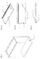
- FIG. 1shows a cooling system employing a 2-phase system 10 to passively cool the north and south bridge chips.
- FIG. 2is a view of an embodiment of a portable, self-contained, liquid submersion cooling, system on a personal computer.
- FIGS. 3A and 3Bare perspective and end views, respectively, showing components of the liquid submersion cooling system of FIG. 2 .
- FIG. 4is a perspective view of the computer case.
- FIGS. 5A , 5 B, and 5 Care perspective top and side views respectively of the lid of the computer case showing the pass-through connector.
- FIG. 6is a detailed illustration of the pass-through connector.
- FIG. 7is a perspective view of the motherboard or main board of the computer.
- FIGS. 8A and 8Bare perspective and side views, respectively, showing daughter cards on the motherboard and showing engagement with the lid.
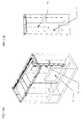
- FIG. 9illustrates a subassembly including the case, motherboard and daughter cards in the case, and the lid.
- FIG. 10illustrates the subassembly of FIG. 9 with a pump within the case.
- FIGS. 11A and 11Bare perspective and end views, respectively, of a subassembly that includes a hard drive within the case.
- FIGS. 12A and 12Bare perspective and end views, respectively, of a subassembly that includes multiple heat exchangers.
- FIGS. 13A and 13Bare perspective and end views, respectively, of a subassembly that includes a single heat exchanger.
- FIG. 14is an end view similar to FIG. 12B showing how convection cooling works.
- FIG. 15is an illustration of a prototype computer that incorporates the liquid submersion cooling system, where the video boards and pump are visible in the case and the radiators are visible, mounted on the sides.
- FIG. 16is an illustration of the prototype computer of FIG. 15 showing the front and top of the case.
- FIG. 17is a perspective view of another embodiment of a portable, self-contained liquid submersion cooling system on a personal computer.
- FIG. 18is a side view of the computer shown in FIG. 17 .
- FIG. 19is an end view of the computer shown in FIG. 17 .
- FIG. 20is a perspective view similar to FIG. 17 but with the motherboard assembly partially lifted from the interior space.
- FIG. 21is an end view of the motherboard assembly removed from the computer.
- FIG. 22is a perspective view of the motherboard assembly.
- FIG. 23is a side view of the motherboard assembly.
- FIG. 24illustrates the motherboard assembly in a raised position.
- FIG. 25is a perspective view of the computer case with the motherboard assembly and lid removed.
- FIG. 26is a side view of the heat exchanger.
- FIG. 27illustrates a pair of heat exchanger plates used to form the heat exchanger.
- FIG. 28is a perspective view of the heat exchanger and fan.
- FIG. 29illustrates a snorkel attachment for use with a hard drive.
- FIGS. 30A , 30 B, and 30 Cillustrate use of the snorkel attachment on a hard drive.
- FIGS. 31A , 31 B, and 31 Cillustrate details of the AC current cut-off mechanism associated with the lid.
- a liquid submersion cooling systemis described that is suitable for cooling, a number of electronic devices, including cooling heat-generating components in computer systems and other systems that use electronic, heat-generating components.
- Examples of electronic devices to which the concepts described herein can be appliedinclude, but are not limited to, desktop computers and other forms of personal computers including laptop computers; console gaming devices, hand-held devices such as tablet computers, wearable computers and personal digital assistants (PDAs); servers including blade servers; disk arrays/storage systems; storage area networks; storage communication systems; work stations; routers; telecommunication infrastructure/switches; wired, optical and wireless communication devices; cell processor devices; printers; power supplies; displays; optical devices; instrumentation systems including baud-held systems; military electronics; etc.
- the conceptswill be described and illustrated herein as applied to a desktop-sized computer. However, it is to be realized that the concepts could be used on other electronic devices as well.
- FIGS. 2 , 3 A and 3 Billustrate one embodiment of a desktop-sized computer 20 employing a liquid submersion cooling system 22 . All active components are illustrated submerged in a tank of dielectric liquid. This system uses a dielectric cooling liquid in direct contact with the electronically and thermally active components of a computer system. Dielectric liquids that can be used in this type of immersive cooling system include, but are not limited to:
- dielectric fluidsalso have the ability to extinguish fires on computer components. By submerging computer components in a dielectric, fire-retardant fluid, the chance of a fire starting due to computer component failure is minimized.
- the lid 2 of the case 1will attach to the connector side of the computer motherboard 30 , shown in FIGS. 7 , 8 A and 8 B, allowing motherboard input/output (IO) connections, daughter card 4 IO and power to be passed in and out of the system.
- Componentssuch as daughter cards 4 , additional processors 6 , power supply card 5 , and memory cards 8 can be added to the system by opening the tank lid 2 and lifting the attached electronics out of the case 1 .
- a hard drive 11can be disposed in the case 1 , with an air line 10 connected to the hard drive breather hole leading from the hard drive to the exterior of the case 1 .
- At least one pump 13will pump warm liquid from the top of the case 1 and pass it through surrounding heat exchangers 3 .
- the pump 13may be submersed in the liquid as shown in FIGS. 3B and 10 , or external to the case 1 .
- Using two external pumps 13 with quick-release hose attachmentswould allow hot-swapping of a failed pump while the other pump maintains system circulation.
- Using one external pump 13 with quick-release hose attachmentswould allow the change-out of a failed pump with only a brief system downtime.
- the heat exchangers 3can act as the outside surface and supporting structure of the computer case 1 .
- the majority of the case wallmay act as a radiator surface.
- ATXAdvanced Technology Extended
- BTXBalanced Technology Extended
- the walls of the heat exchangers 3may be tapered upward, like a cooling tower on a boiler. This tapering will help accelerate convection currents, making it possible to cool the system without the use of air-moving devices, such as thus.
- the case 1is large enough to contain all of the active computer components that require cooling. It may also be necessary to leave space for liquid return lines 48 with nozzles over critical components that require cooling. Nozzles may be incorporated to direct the flow of the return liquid at specific, high-temperature areas like the CPUs.
- the lid 2not only provides a liquid- and gas-tight seal for the case 1 , but it also contains a pass-through connector 7 that allows external component IO, storage IO and power to pass into and out of the case 1 , to and from the computer motherboard 30 and its components.
- the lid 2will have a gasket that will seal the case 1 .
- the lid 2may also contain a fill port 32 for filling the case 1 with coolant.
- the motherboard 30is essentially functionally the same as in current ATX or BTX specification boards, with the exception being that it does not have the same IO and power connectors. Instead, the top edge of the board is lined with a series of conductive pads 34 that are contacts for engaging the pass-through connector 7 that is part of the lid 2 .
- Multiple motherboards or other circuit boardsmay be employed to allow stacking of extra processors 6 or other components for additional computing power or to allow for multiple computers within a single tank enclosure. This cooling system would allow for numerous computer systems to be cooled in a single tank or individual tanks which may be interconnected to create a server or workstation rack system.
- daughter cards 4connect to the motherboard 30 as they do with current ATX or BTX specification boards.
- Daughter cards 4can include video cards and other PCI or PCIE cards that require IO pass-through to the outside of the case 1 .
- These daughter cards 4will require liquid- and gas-tight gaskets in order to allow external IO connections.
- the power supply 5may also be a daughter card 4 , with no power supply to motherboard wiring required.
- the power supplymay also be directly integrated into the motherboard. External alternating current (AC) connections would be made through a pass-through connector into the liquid-filled tank with a liquid and gas-tight gasket.
- ACalternating current
- the pass-through connector 7is integrated into the lid 2 in such a way that it creates a liquid- and gas-tight electrical conduit for IO and power connectivity. It attaches to the motherboard 30 on the inside of the case 1 and leads to a connector break-out 36 on the outside of the tank 1 .
- the pump 13(or pumps) is either internally-mounted within the case 1 , submersed in the liquid as shown in FIG. 10 , or externally mounted.
- the pumpis used to circulate warn coolant from inside the tank 1 to outside of the tank 1 within the heat exchangers 3 . Liquid may also be circulated through external hard drive cooling plates as well.
- the pump 13can be wired such that it can be turned on to circulate liquid even if the computer is off. Or the pump 13 can be wired to turn on only when the computer is on. After the computer is shut off, there is more than sufficient thermal capacity in the liquid within the case 1 to remove residual heat from the submerged components. This would ensure that there is no post-shut down thermal damage.
- the pump 13is illustrated in the lower left corner of the case 1 .
- Warm coolantis pumped from the top of the tank 1 to outside of the tank 1 into the heat exchangers 3 .
- the pump(s) 13may alternatively be attached to the lid 2 of the computer. This would allow for direct intake of fluids from the warmest region of the tank 1 and make maintenance and replacement of warn-out pumps much easier.
- the hard drives or other internal storage systems 11can also be submerged.
- the air line 10could be fixed over the breather hole, allowing an open-air connection to the outside of the tank 1 .
- the rest of the drive 11would be sealed as to be gas and liquid impermeable.
- the processors 6mount to the motherboard 30 via normal, vender-specified sockets. Testing has shown that no heat sinks or other appliances need to be attached to the processors 6 in order to cool them sufficiently for normal, vendor-specified temperatures. However, if lower operating temperatures or a higher level of heat transfer is required for processor 6 over-clocking, heat sinks, which greatly increase the exposed surface area of heat conduction from the processor(s) 6 , may be employed.
- the heat exchangers 3 or heat exchanger surfacesmay serve as the external shell or case of the computer 20 .
- warm cooling liquidis pumped from within the case 1 to the heat exchangers 3 , the liquid is cooled to ambient temperature. Cooling of liquids utilizing a heat exchanger 3 can be accomplished by one of several means:
- the heat exchangers 3are designed such that they angle inward and upward, creating a cooling tower effect, as seen on industrial boilers.
- This taperwill serve to create thermal conduction that draws more cool air from near the bottom of the case 1 and allows it to migrate naturally upward and out of the top of the heat exchangers 3 .
- Cool-air inlet ports(not shown) at the base of the heat exchangers can be covered with filter material in order to keep dust and other foreign matter out of the heat exchangers, while allowing air to enter.
- a fan or multiple fansmay be used to aid in the upward flow of air through the cooling system.
- the cooled liquidAs the cooled liquid is pumped back into the case 1 , it may be sent through tubes or other deflection/routing means to injector head assemblies that serve to accelerate coolant across the most thermally active components. This accelerated liquid would help to create turbulent flow of coolant across the heated surface. This turbulent flow would break down natural laminate flow, which is poor at conducting heat through a liquid because only the first few molecules of liquid that are in contact with the heated surface can actually take heat energy away from the heated surface.
- the computer 20can also include external, removable storage drives such as CD, DVD, floppy and flash drives (not illustrated).
- external IO, power button and other human interface controlswould attach to the pass-through connector 7 and be mounted on a rigid circuit board or flex circuit.
- FIG. 12Billustrates one possible flow path of liquid through the multiple heat exchangers 3 :
- Cooling liquidflows from the heat exchanger through a passageway 48 back into the case 1 near the bottom thereof where it is warmed by the heat-generating electronics and components and rises back to the top of the case 1 and the cycle begins again.
- a single heat exchanger 3 as shown in FIGS. 13A and 13Bcan be used in the cooling system through the following steps.
- the computer systemcan be cooled via active or passive convection cooling, as shown in FIG. 14 .
- active or passive convection coolingRather than forcing, air from the front of the case to the back of the case, as seen in conventional designs, air is allowed to travel vertically. Heat rises, and the cooling system 22 design takes advantage of this, as described in the following steps.
- Air flowmay be aided by the use of an air-moving device or devices such as one or more fans mounted on the top or bottom of the cooling stack. However, for some applications only passive, convection-induced air flow may be required.
- FIGS. 15-16illustrate a prototype computer 80 that incorporates the liquid submersion cooling system 22 . Due to the clear case, the video boards and pump are visible in the case and the heat exchangers are visible, mounted on the sides of the case.
- FIGS. 17-19illustrate another embodiment of a personal computer 100 employing an alternative liquid submersion cooling system 102 .
- the computer 100includes a case 104 that has a liquid-tight interior space 106 ( FIG. 20 ) designed to be leak-proof so that it can be filled with a coolant liquid.
- the word “case”is meant to include a housing, an enclosure, and the like.
- the side wall 107 of the casedefines at least one side of the interior space 106
- a portion 109 of the side wall 107is made of translucent, preferably transparent, material to allow viewing inside the space 106 .
- the material used for the portion 109can be any material suitable for forming a leak-proof container and, if viewing of the internal computer components is desired, the material should be translucent or transparent.
- An example of a suitable materialis a polycarbonate.
- the case 104also includes non-liquid tight space 111 next to the liquid-tight interior space 106 in which components of the computer 100 and the cooling system 102 are disposed as described below.
- the case 104includes a lid 108 that closes the top of the case 104 , but which can be removed to permit access to the spaces 106 , 111 .
- the lid 108includes a seal 113 (shown in FIGS. 21 and 22 ) for forming a liquid-tight seal with the interior space 106 of the case when the lid 108 is in position closing the case.
- the lid 108includes a handle 110 that facilitates grasping of the lid 108 and lifting of any internal computer components connected thereto out of the interior space 106 .
- the lid 108also includes a pass-through connector 112 (partially visible in FIG.
- an AC current cut-off mechanism 115is also provided, as shown in FIGS. 31A-C , such that when the lid 108 is opened, electrical power in the computer is shut off, preventing operation of any electrical components.
- the mechanism 115may be accomplished by routing AC power through a bridge board 400 that is contained in, or otherwise connected to, the lid 108 .
- the board 400is connected to the motherboard assembly 114 comprised of a motherboard 302 and a support 300 member.
- the board 400includes an AC power socket 402 for receiving AC power.
- a neutral line 404 and a ground line 406leads from the power socket 402 to a pass-through connector 112 leading to the interior space 106 .
- a hot or live wire 408leads from the socket 402 to a second pass-through connector 112 leading to the space 111 , passes under the board 400 and back to the top of the board 400 to a return portion 410 that connects to the pass through connector 112 to pass AC power into the interior space 106 .
- An external board 412illustrated in FIG. 31C , is fixed in the space 111 .
- the board 402includes a u-shaped connector 414 at the top thereof, one end of which connects to the hot wire 408 and the other end of which connects to the return portion 410 when the lid 108 is in place.
- the hot wire 408becomes disengaged from the connector 414 on the external board 412 , opening the electrical circuit and disconnecting AC power from the interior space.
- the current cut-off mechanism 115may also be accomplished, by routing AC power through two pins on the bridge board 400 . These pins would be shorted, passing current back to the external board 412 .
- the bridge board 400becomes disengaged from the connector 414 on the external hoard 412 .
- the lid 108also includes an opening 116 through which liquid can be added into the space 106 .
- the opening 116is closed by a removable cap which is removed when liquid is to be added.
- the lid 108can also include a lock mechanism (not shown) that locks the lid in place.
- the case 104can include a drain valve 118 (shown schematically) that can be opened in order to drain liquid from the case.
- the valve 118can be any type of valve that can be opened and closed, preferably manually, for draining the case.
- the valve 118is illustrated as being positioned at the bottom of the interior space at the bottom of the case 104 . However, the valve can be positioned at any other suitable location on the case.
- the front portion of the case 104can have a touch screen display that allows users to run the computer 100 from the front without plugging in a monitor.
- the motherboard assembly 114acts as a support for many of the internal components of the computer 100 .
- the motherboard assembly 114is removable and disposed in the interior space 106 to permit the motherboard assembly to be lifted from the case when the lid 108 is lifted upward.
- the motherboard assembly 114includes a support member 300 on which is disposed a motherboard 302 that supports the submerged components.
- the motherboard assembly 114is fixed to the lid 108 via flanges 122 at the top end of the motherboard 114 , shown in FIG. 24 , that connect to the pass-through connector 112 .
- a pair of tabs 123 that are fixed to the support member 300are connected to the lid 108 .
- FIG. 23An exemplary layout of the motherboard components is illustrated in FIG. 23 .
- the layoutis designed to render the motherboard nearly or completely 302 wire-free and facilitate movement of cooling liquid in the interior space 106 .
- the motherboard 302is illustrated as having mounted thereto four CPUs and/or GPUs 124 , video/motherboard memory cards 126 , memory cards 127 , power supply 128 , and controller chips 130 . These components are laid out relative to each other to define a number of vertical and horizontal liquid flow channels that aid in the flow of liquid.
- vertical channelsinclude channel 132 A between the CPUs/GPUs 124 , channels 132 B between the controller chips 130 , and channels 132 C between the CPUs/GPUs and the memory cards 126 , 127 .
- Horizontal channelsinclude, for example, channel 134 A between the CPUs/GPUs, channel 134 B between the CPUs/GPUs and the controller chips 130 , and channel 134 C between the CPUs/GPUs and the power supply 128 .
- a plurality of sets of light-emitting diodes (LEDs) 136that can produce a desired color/wavelength of light, such as ultraviolet, can also be mounted to the motherboard 114 at dispersed locations. When illuminated, the LEDs 136 give the liquid in the interior space 106 a luminescent glow.
- LEDslight-emitting diodes
- heat sinkscan be affixed to some or all of the heat-generating components on the motherboard 302 .
- the use of heat sinkswill depend on the amount of heat generated by a particular component and whether it is determined that additional heat dissipation than that provided by direct contact with the liquid is necessary for a particular component.
- heat sinks 140are shown attached to the CPUs/GPUs 124 and the controller chips 130 .
- the heat sinks 140each comprise a plurality of elongated fins 142 that extend from a base plate 144 fixed to the component.
- the fins 142 and plate 144conduct heat away from the component.
- the fins 142define flow channels therebetween that allow the cooling liquid to flow through and past the plurality of fins to transfer heat to the liquid.
- Heat sinks 150are also attached to the memory cards 126 , 127 and the power supply 128 .
- the heat sinks 150are similar to the heat sinks 140 , including fins 152 connected to a base plate 154 fixed to the component.
- the fins 152are short, having an axial length significantly less than the fins 142 . Nonetheless, the fins 152 define flow channels therebetween which allow the cooling liquid to flow through and past the plurality of fins to transfer heat to the liquid.
- the motherboard assembly 114is removable and disposed in the interior space 106 to permit the motherboard assembly to be lifted from the space when the lid 108 is lifted upward.
- the interior space 106 of the case 104includes a pair of channels 160 at opposite ends of the walls that define the interior space. Each channel 160 extends from the top of the walls to the bottom, and are continuous from top to bottom.
- the side edges of the motherboard assemblyare provided with slides 162 that are sized and configured to slide within the channels 160 . The channels 160 and the slides 162 help guide the motherboard assembly 114 when it is lifted upward from the case and when it is lowered back into the interior space.
- one or more slide locking mechanisms 170can be provided to retain the motherboard assembly 114 at a raised position outside the interior space 106 .
- Two slide locking mechanisms 170are illustrated. However, a single slide locking mechanism could be used if found sufficient to retain the motherboard assembly at the raised position. By keeping the motherboard assembly raised, maintenance and/or replacement of motherboard components is facilitated, while also allowing liquid to drain down into the interior space 106 when the assembly 114 is lifted upward.
- the slide locking mechanisms 170can have a number of configurations.
- the illustrated embodimentis shown to include a stop member 172 that forms part of the slide 162 .
- the stop member 172is pivotally connected to the motherboard assembly so that it can rotate between the position shown in FIGS. 21-23 and the position shown in FIG. 24 .
- the stop member 172is biased by a spring (not shown) to bias the stop member in a counterclockwise direction (when viewing FIG. 21 ) so that when the motherboard assembly is lifted upward, the stop member(s) automatically rotate to the position shown in FIG. 24 when the stop members 172 clear the channels 160 .
- the stop member 172is prevented from further rotation in the counterclockwise direction to prevent the motherboard assembly from falling back down into the interior space 106 due to interference between the stop member(s) 172 and the structure forming the channels 160 .
- the motherboard assemblyis lifted further upward, and the stop member(s) manually rotated in a clockwise direction to the position shown in FIGS. 21-23 . The assembly is then lowered down into the case.
- the submersion cooling system 102includes a heat exchanger 180 mounted in the space 111 within the case 104 , a pump 210 mounted on the motherboard 302 inside the interior space 106 , and a dielectric cooling liquid within the interior space 106 .
- the interior spaceshould contain enough dielectric, cooling liquid to submerge the components that one wishes to be submerged.
- the cooling liquidmay substantially fill the interior space 106 , whereby all heat-generating components on the motherboard are submerged.
- the cooling system 102is designed to direct heated dielectric liquid from inside the space 106 and into the heat exchanger 180 outside the space 106 where the liquid is cooled. The cooled liquid is then returned to the space 106 .
- the heat exchanger 180is positioned outside of the space and substantially forms an outer wall of the computer 100 as shown in FIG. 18 .
- the heat exchanger 180is configured to allow passage therethrough of the liquid for cooling.
- the heat exchanger 180is of a size to form substantially one wall of the case 104 .
- the heat exchanger 180includes an inlet 182 through which cooling liquid enters, an outlet 184 through which cooling liquid exits, and at least one flow path for cooling liquid through the heat exchanger extending from the inlet 182 to the outlet 184 .
- the heat exchanger 180can take on a number of different configurations, as long as it is able to cool the liquid down to an acceptable temperature prior to being fed back into the space 106 .
- An exemplary configuration of the heat exchanger 180is shown in FIGS. 26 and 27 .
- the heat exchanger 180comprises a plurality of identical plates 186 that are connected together. Each plate 186 includes a hole 188 , 190 at each end that during use form plenums that receive the dielectric liquid.
- the plate 186also includes a first plurality of holes 192 defined by bosses that extend in one direction, and a second plurality of holes 194 defined by bosses that extend in the opposite direction.
- the holes 188 , 190are also defined by bosses that extend in the same direction as the bosses defining the holes 192 .
- a central portion 196 of the plate 186is bulged in the direction of the bosses of the holes 188 , 190 , 192 , so that the opposite side of the plate 166 is recessed 198 below a surrounding rim 200 .
- a first plate 186 Ais flipped over as shown in FIG. 27 , and the two plates 186 A, 1868 then secured together such as by soldering along the rim 200 .
- the two holes 188are aligned at the top, and the two holes 190 are aligned at the bottom.
- the bosses that define the holes 194engage with each other to form a number of air passages between the two plates 186 A, 1868 .
- the recesses 198allow liquid to flow downward from the holes 188 , past the engaged bosses of the holes 194 , and down to the holes 190 .
- a third plate 186is then connected to one of the plates 186 A, 186 B, with the third plate being flipped over relative to the plate to which it is connected.
- the bosses that define the holes 188 , 190will engage each other, as will the bosses that define the holes 192 .
- Thiswill create a series of air flow paths 202 on the outside of the heat exchanger as shown in FIG. 26 .
- This process of adding plates 186is repeated to create the size of heat exchanger needed. For the two plates at opposite ends of the heat exchanger 180 , the holes 192 , 194 will be closed off to prevent escape of liquid.
- an inlet fitting 204 defining the inlet 182will be connected to the boss defining the opening 188
- an outlet fitting 206 defining the outlet 184will be connected to the boss defining the opening 190 .
- the openings 188 , 190are closed by suitable caps 208 .
- liquid to be cooledflows into the inlet 182 and into the plenum at the top of the heat exchanger defined by the holes 188 .
- the liquidis able to flow downward in the recesses 198 past the bosses of the holes 194 . As it does, the liquid transfers heat to the bosses.
- aircan flow into the aligned bosses of the holes 194 to pick up heat. Air also flows into the flow paths 202 for additional heat exchange with the bulged central portion 196 .
- the cooled liquidcollects in the plenum defined by the aligned holes 190 , and is pumped through the outlet 184 and back into the space 106 by the pump 210 .
- the pump 210is mounted on the motherboard 302 and in use is submerged in the dielectric liquid.
- the pump 210is sized to be able to circulate liquid to outside the space, through the heat exchanger, and back into the space.
- the pump 210is illustrated as a centrifugal pump having an inlet 212 and an outlet 214 .
- the inlet 212receives liquid therethrough from the space 106 , and pumps it through the outlet 214 connected to an outlet port 218 formed on the lid 108 .
- the outlet port 218extends through the lid 108 and is fluidly connected to the heat exchanger inlet 182 by suitable tubing.
- the heat exchanger outlet 184is fluidly connected by suitable tubing to an inlet port 222 formed through the lid to direct liquid back into the space 106 .
- a spray bar assembly 230is connected to the inlet port 222 .
- the spray bar assembly 230includes a central passageway 231 extending along the vertical channel 132 A, and plurality of branches or vents 232 that extend along the horizontal channels 134 A-C (and at the bottom of the space 106 ).
- the branches 232include holes 234 ( FIG. 20 ) to direct cooled liquid directly onto the components 124 , 126 , 127 , 128 , 130 .
- the holes 234are in the top of the branches 232 to direct liquid upwardly. However, holes could also be provided at the bottom of the branches to directed liquid downwardly onto the components.
- An air-moving devicecan be provided to create a flow of air past the heat exchanger.
- a number of different air-moving devicescan be used, for example, a fan or an ionization device.
- the drawingsillustrate the use of a fan 240 to create air movement past the heat exchanger 180 .
- the fan 240is best seen in FIGS. 20 , 25 , and 28 .
- the fan 240is positioned at the bottom of the computer 100 at the base of the heat exchanger 180 .
- the fanis a squirrel-cage type fan with an air outlet 241 that extends substantially across the entire length of the heat exchanger in order to create air flow across the entire heat exchanger.
- An air filteris located in front of the inlet of the fan 240 in order to filter the air.
- the air filter 242can be any suitable type of air filter, for example, a high-efficiency particulate air (HEPA) filter.
- HEPAhigh-efficiency particulate air
- the filter 242is mounted so as it is able to slide and be removable from the case 104 by pulling on a handle 243 . This permits the filter 242 to be cleaned or replaceable with a replacement filter. Air is drawn into the filter and the fan via a series of air vents 244 ( FIG. 18 ) on the side of the computer.
- HEPAhigh-efficiency particulate air
- the computer 100can also include additional features, such as a drive mechanism 250 external to the case 104 .
- the drive mechanism 250can be a DVD drive, a floppy drive, a CD drive, a Blu-ray drive, HD drive, and the like.
- one or more hard drives 252are accessible from the opposite side of the case 104 .
- the hard drives 252can be mounted so as to permit easy replacement with replacement hard drives.
- FIGS. 29 and 30 A-Cillustrate a snorkel attachment 260 that can be connected to a breather hole 261 (see FIG. 30A ) on a hard drive to aid in achieving the pressure equilibrium.
- the snorkel attachment 260includes a circular cap 262 that is designed to fit around the breather hole 261 (see FIG. 30B ) and form a liquid tight seal with the hard drive 252 to prevent entry of liquid.
- a fitting 264extends from the cap 262 , and a breather conduit 266 connects to the fitting 264 .
- the breather conduit 266can be directed to the outside of the space 106 , or the conduit 266 can connect to a fitting extending through the lid 108 .
- the snorkel attachment 260permits achievement of pressure equilibrium between the hard drive and outside air pressure, allowing the hard drive to function properly while submerged in the dielectric liquid.
- the dielectric liquid that is used in the computer 100can be any of the dielectric liquids discussed above.
- a soy-based dielectric liquidcan be used.
- a colorant materialcan be added to the dielectric liquid to make the liquid a particular color. Because the portion 109 of the side wall 107 is clear, adding a colorant to the liquid will change the visual impact of the computer.
Landscapes
- Engineering & Computer Science (AREA)
- Microelectronics & Electronic Packaging (AREA)
- Physics & Mathematics (AREA)
- Thermal Sciences (AREA)
- Theoretical Computer Science (AREA)
- General Engineering & Computer Science (AREA)
- Human Computer Interaction (AREA)
- General Physics & Mathematics (AREA)
- Computer Hardware Design (AREA)
- Cooling Or The Like Of Electrical Apparatus (AREA)
Abstract
Description
- A compressor, as is the case with typical refrigeration systems
- Peltier effect cooling
- Active air cooling of the radiator surface using a fan or other air-moving mechanism
- Passive cooling by exposing as large of a thermally conductive heat exchange surface as possible to lower ambient temperatures
- 1. Liquid is pumped out of the
case 1 from the warm upper area of thecase 1 by thepump 13 through aninlet pipe 40 and out a discharge pipe42 (seeFIG. 10 ); thedischarge pipe 42 is connected to aninlet 44 of theheat exchanger 3. - 2. Liquid flows through and is cooled by the
heat exchanger 3 that is also one side wall of the computer case. - 3. A
connection 46 allows liquid to pass through from theheat exchanger 3 on one side of thecase 1 to theheat exchanger 3 on the other side of thecomputer case 1. - 4. Coolant flows through the
heat exchanger 3 on the other side of thecase 1.
- 1. Liquid is pumped out of the
- 1. Liquid is pumped out of the
case 1 from the warm upper area of the tank as in the embodiment inFIG. 12B . - 2. Liquid flows through and is cooled by the
heat exchanger 3 that is on one side wall of thecomputer case 1. - 3. Cooling liquid flows back to the bottom area of the
tank 1 through apassageway 50 where it is warmed and rises back to the top of thecase 1, and the cycle begins again.
- 1. Liquid is pumped out of the
- 1. Cool air from underneath the computer is drawn upward as shown by
arrows 52. - 2. The
heat exchangers 3 are designed to allow the cool air to flow upward between the heat exchangers and the outside of thecase 1. As heat is dissipated from the coolant inside theheat exchangers 3, the cooler air around theheat exchangers 3 is heated and rises. - 3. The air flows through the
heat exchangers 3 and is expelled at the sides and top of the system. This rising air helps to pull more cool air into the system, much like a cooling tower for a boiler.
- 1. Cool air from underneath the computer is drawn upward as shown by
Claims (20)
Priority Applications (1)
| Application Number | Priority Date | Filing Date | Title |
|---|---|---|---|
| US12/902,375US8009419B2 (en) | 2006-05-16 | 2010-10-12 | Liquid submersion cooling system |
Applications Claiming Priority (4)
| Application Number | Priority Date | Filing Date | Title |
|---|---|---|---|
| US80071506P | 2006-05-16 | 2006-05-16 | |
| US11/736,947US7403392B2 (en) | 2006-05-16 | 2007-04-18 | Liquid submersion cooling system |
| US12/111,498US7911782B2 (en) | 2006-05-16 | 2008-04-29 | Liquid submersion cooling system |
| US12/902,375US8009419B2 (en) | 2006-05-16 | 2010-10-12 | Liquid submersion cooling system |
Related Parent Applications (1)
| Application Number | Title | Priority Date | Filing Date |
|---|---|---|---|
| US12/111,498ContinuationUS7911782B2 (en) | 2006-05-16 | 2008-04-29 | Liquid submersion cooling system |
Publications (2)
| Publication Number | Publication Date |
|---|---|
| US20110075353A1 US20110075353A1 (en) | 2011-03-31 |
| US8009419B2true US8009419B2 (en) | 2011-08-30 |
Family
ID=38711268
Family Applications (3)
| Application Number | Title | Priority Date | Filing Date |
|---|---|---|---|
| US11/736,947ActiveUS7403392B2 (en) | 2006-05-16 | 2007-04-18 | Liquid submersion cooling system |
| US12/111,498Active2028-03-20US7911782B2 (en) | 2006-05-16 | 2008-04-29 | Liquid submersion cooling system |
| US12/902,375ActiveUS8009419B2 (en) | 2006-05-16 | 2010-10-12 | Liquid submersion cooling system |
Family Applications Before (2)
| Application Number | Title | Priority Date | Filing Date |
|---|---|---|---|
| US11/736,947ActiveUS7403392B2 (en) | 2006-05-16 | 2007-04-18 | Liquid submersion cooling system |
| US12/111,498Active2028-03-20US7911782B2 (en) | 2006-05-16 | 2008-04-29 | Liquid submersion cooling system |
Country Status (7)
| Country | Link |
|---|---|
| US (3) | US7403392B2 (en) |
| EP (1) | EP2021898A4 (en) |
| JP (2) | JP2009537905A (en) |
| KR (1) | KR101437702B1 (en) |
| CN (1) | CN101443724B (en) |
| TW (1) | TWI468910B (en) |
| WO (1) | WO2007137018A1 (en) |
Cited By (53)
| Publication number | Priority date | Publication date | Assignee | Title |
|---|---|---|---|---|
| US20110132579A1 (en)* | 2008-08-11 | 2011-06-09 | Green Revolution Cooling, Inc. | Liquid Submerged, Horizontal Computer Server Rack and Systems and Method of Cooling such a Server Rack |
| US8467189B2 (en) | 2008-04-21 | 2013-06-18 | Liquidcool Solutions, Inc. | Case and rack system for liquid submersion cooling of electronic devices connected in an array |
| US20130194755A1 (en)* | 2012-01-30 | 2013-08-01 | Wei Ling | Board-level heat transfer apparatus for communication platforms |
| WO2014040182A1 (en)* | 2012-09-14 | 2014-03-20 | Marc-Antoine Pelletier | Apparatus and methods for cooling a cpu using a liquid bath |
| US20140216686A1 (en)* | 2013-02-01 | 2014-08-07 | Dell Products L.P. | Partitioned, Rotating Condenser Units to Enable Servicing of Submerged IT Equipment Positioned Beneath a Vapor Condenser Without Interrupting a Vaporization-Condensation Cycling of the Remaining Immersion Cooling System |
| US8913383B1 (en)* | 2012-02-28 | 2014-12-16 | Heatmine LLC | Heat capture system for electrical components providing electromagnetic pulse protection |
| USD724081S1 (en)* | 2013-03-05 | 2015-03-10 | Hewlett-Packard Development Company, L.P. | Top loading fan cartridge |
| US20150070846A1 (en)* | 2013-02-01 | 2015-03-12 | Dell Products L.P. | System and Method for Powering Multiple Electronic Devices Operating Within an Immersion Cooling Vessel |
| US9258926B2 (en) | 2014-06-24 | 2016-02-09 | David Lane Smith | System and method for fluid cooling of electronic devices installed in a sealed enclosure |
| US20160128231A1 (en)* | 2014-11-03 | 2016-05-05 | General Electric Company | System and method for cooling electrical components of a power converter |
| US9408332B2 (en) | 2014-06-24 | 2016-08-02 | David Lane Smith | System and method for fluid cooling of electronic devices installed in a sealed enclosure |
| US9504190B2 (en) | 2013-05-06 | 2016-11-22 | Green Revolution Cooling, Inc. | System and method of packaging computing resources for space and fire-resistance |
| US9560789B2 (en) | 2014-06-24 | 2017-01-31 | David Lane Smith | System and method for fluid cooling of electronic devices installed in a sealed enclosure |
| US9593876B2 (en) | 2012-09-07 | 2017-03-14 | David Smith | Cooling electronic devices installed in a subsurface environment |
| US9699939B2 (en) | 2014-06-24 | 2017-07-04 | David Lane Smith | System and method for fluid cooling of electronic devices installed in a sealed enclosure |
| US9756766B2 (en) | 2014-05-13 | 2017-09-05 | Green Revolution Cooling, Inc. | System and method for air-cooling hard drives in liquid-cooled server rack |
| RU2645721C2 (en)* | 2012-12-14 | 2018-02-28 | МИДАС ГРИН ТЕКНОЛОДЖИ, ЭлЭлСи | Cooling system by diving electrical instruments in liquid |
| US10178807B2 (en) | 2013-03-26 | 2019-01-08 | Hewlett Packard Enterprise Development Lp | Top loading cartridge |
| US10477726B1 (en) | 2018-09-19 | 2019-11-12 | TMGCore, LLC | Liquid immersion cooling platform |
| RU2706511C1 (en)* | 2019-05-21 | 2019-11-19 | Роман Николаевич Горобец | Two-phase contactless electronic components cooling system |
| US10617032B1 (en) | 2018-09-19 | 2020-04-07 | TMGCore, LLC | Robot for a liquid immersion cooling system |
| US10624237B2 (en) | 2018-09-19 | 2020-04-14 | TMGCore, LLC | Liquid immersion cooling vessel and components thereof |
| US10645841B1 (en)* | 2019-03-08 | 2020-05-05 | Hongfujin Precision Electronics (Tianjin) Co., Ltd. | Cooling device |
| US10653043B2 (en) | 2018-09-19 | 2020-05-12 | TMGCore, LLC | Vapor management system for a liquid immersion cooling system |
| US10694643B2 (en) | 2018-09-19 | 2020-06-23 | TMGCore, LLC | Ballast blocks for a liquid immersion cooling system |
| US10969842B2 (en) | 2018-09-19 | 2021-04-06 | TMGCore, LLC | Chassis for a liquid immersion cooling system |
| US11071238B2 (en)* | 2016-11-25 | 2021-07-20 | Iceotope Group Limited | Fluid cooling system |
| US11129298B2 (en) | 2018-09-19 | 2021-09-21 | Tmgcore, Inc. | Process for liquid immersion cooling |
| US11191186B2 (en) | 2014-06-24 | 2021-11-30 | David Lane Smith | System and method for fluid cooling of electronic devices installed in an enclosure |
| US11359865B2 (en) | 2018-07-23 | 2022-06-14 | Green Revolution Cooling, Inc. | Dual Cooling Tower Time Share Water Treatment System |
| US11421921B2 (en) | 2012-09-07 | 2022-08-23 | David Lane Smith | Cooling electronic devices installed in a subsurface environment |
| USD982145S1 (en) | 2020-10-19 | 2023-03-28 | Green Revolution Cooling, Inc. | Cooling system enclosure |
| US11729950B2 (en) | 2021-04-01 | 2023-08-15 | Ovh | Immersion cooling system with dual dielectric cooling liquid circulation |
| US11744041B2 (en) | 2014-06-24 | 2023-08-29 | David Lane Smith | System and method for fluid cooling of electronic devices installed in an enclosure |
| US11785747B2 (en) | 2018-11-16 | 2023-10-10 | TMGCore. INC. | Methods and devices for testing immersion cooling controllers |
| US11805624B2 (en) | 2021-09-17 | 2023-10-31 | Green Revolution Cooling, Inc. | Coolant shroud |
| US11895804B2 (en) | 2018-09-19 | 2024-02-06 | Tmgcore, Inc. | Fluid breakdown detection systems and processes useful for liquid immersion cooling |
| US11903163B2 (en) | 2021-10-11 | 2024-02-13 | Tmgcore, Inc. | Methods and devices to employ air cooled computers in liquid immersion cooling |
| US11924998B2 (en) | 2021-04-01 | 2024-03-05 | Ovh | Hybrid immersion cooling system for rack-mounted electronic assemblies |
| US11925946B2 (en) | 2022-03-28 | 2024-03-12 | Green Revolution Cooling, Inc. | Fluid delivery wand |
| US12035508B2 (en) | 2020-12-29 | 2024-07-09 | Modine LLC | Liquid immersion cooling platform and components thereof |
| US12049239B2 (en) | 2021-11-12 | 2024-07-30 | Modine LLC | Distributed computing network comprised of autonomous vehicles carrying liquid immersion cooling platforms |
| US12089368B2 (en) | 2022-09-14 | 2024-09-10 | Green Revolution Cooling, Inc. | System and method for cooling computing devices using a primary circuit dielectric cooling fluid |
| US12120847B1 (en) | 2021-03-23 | 2024-10-15 | Engendren LLC | Container for one or more electronic devices and methods of use thereof |
| US12120846B2 (en) | 2021-04-01 | 2024-10-15 | Ovh | Immersion cooling systems for electronic components |
| US12137536B2 (en) | 2021-04-01 | 2024-11-05 | Ovh | Systems and methods for autonomously activable redundant cooling of a heat generating component |
| US12144145B2 (en) | 2021-04-01 | 2024-11-12 | Ovh | Data center rack system with integrated liquid and dielectric immersion cooling |
| US12317450B1 (en) | 2021-11-08 | 2025-05-27 | Rhodium Technologies LLC | Fluid circulation systems and methods for cooling having a collector |
| US12389566B2 (en) | 2020-11-12 | 2025-08-12 | Green Revolution Cooling, Inc. | Multi-rack immersion cooling distribution system |
| US12402271B2 (en) | 2012-12-14 | 2025-08-26 | Midas Green Technologies, Llc | Appliance immersion cooling system |
| RU236947U1 (en)* | 2025-05-12 | 2025-09-01 | Федеральное государственное бюджетное учреждение науки Дагестанский федеральный исследовательский центр Российской академии наук | Universal quick-release cooled platform for installing heat-generating functional units in an uncooled vacuum chamber |
| US12408308B2 (en) | 2018-11-16 | 2025-09-02 | Modine LLC | Hydrofire rods for liquid immersion cooling platform |
| US12414273B2 (en) | 2023-01-25 | 2025-09-09 | Green Revolution Cooling, Inc. | Immersion cooling reservoir level control |
Families Citing this family (158)
| Publication number | Priority date | Publication date | Assignee | Title |
|---|---|---|---|---|
| FR2876812B1 (en)* | 2004-10-15 | 2006-12-22 | J C C Chereau Aeronautique | COOLING FLUID DEVICE FOR COMPUTER |
| DE102005014534A1 (en)* | 2005-03-30 | 2006-10-05 | Hush Technologies Investments Ltd. | Housing for a computer |
| US8240359B2 (en)* | 2006-04-17 | 2012-08-14 | Gerald Garrett | Liquid storage and cooling computer case |
| US20080017355A1 (en)* | 2006-05-16 | 2008-01-24 | Hardcore Computer, Inc. | Case for a liquid submersion cooled electronic device |
| US7403392B2 (en)* | 2006-05-16 | 2008-07-22 | Hardcore Computer, Inc. | Liquid submersion cooling system |
| DE102008044645B3 (en)* | 2008-08-27 | 2010-02-18 | Airbus Deutschland Gmbh | An aircraft signal computer system comprising a plurality of modular signal processor units |
| US7916483B2 (en) | 2008-10-23 | 2011-03-29 | International Business Machines Corporation | Open flow cold plate for liquid cooled electronic packages |
| US7961475B2 (en) | 2008-10-23 | 2011-06-14 | International Business Machines Corporation | Apparatus and method for facilitating immersion-cooling of an electronic subsystem |
| US7724524B1 (en)* | 2008-11-12 | 2010-05-25 | International Business Machines Corporation | Hybrid immersion cooled server with integral spot and bath cooling |
| US20100147492A1 (en)* | 2008-12-10 | 2010-06-17 | Ronald David Conry | IGBT cooling method |
| US8305759B2 (en)* | 2009-03-09 | 2012-11-06 | Hardcore Computer, Inc. | Gravity assisted directed liquid cooling |
| US8369090B2 (en) | 2009-05-12 | 2013-02-05 | Iceotope Limited | Cooled electronic system |
| US20110007474A1 (en)* | 2010-06-30 | 2011-01-13 | Detore Richard E | Combined computer device and facility air purification |
| CN101968670A (en)* | 2009-07-27 | 2011-02-09 | 鸿富锦精密工业(深圳)有限公司 | All-in-one computer |
| BR112012008138A2 (en)* | 2009-07-30 | 2019-09-24 | Tendris Solutions Bv | algae reactor |
| KR101084349B1 (en)* | 2009-10-21 | 2011-11-17 | 주식회사 자온지 | Manufacturing method of heat pipe type radiator |
| US20110108250A1 (en)* | 2009-11-09 | 2011-05-12 | Alex Horng | Heat Dissipating device |
| US8289729B2 (en)* | 2010-02-26 | 2012-10-16 | Corsair Memory, Inc. | PCB interconnect scheme for PSU |
| US20110212634A1 (en)* | 2010-02-26 | 2011-09-01 | Lieberman Donald | Ac interconnect scheme for psu |
| US8791605B2 (en)* | 2010-02-26 | 2014-07-29 | Corsair Memory, Inc. | DC interconnect scheme for PSU |
| US8279597B2 (en) | 2010-05-27 | 2012-10-02 | International Business Machines Corporation | Heatsink allowing in-situ maintenance in a stackable module |
| US8174826B2 (en) | 2010-05-27 | 2012-05-08 | International Business Machines Corporation | Liquid cooling system for stackable modules in energy-efficient computing systems |
| US8179674B2 (en) | 2010-05-28 | 2012-05-15 | International Business Machines Corporation | Scalable space-optimized and energy-efficient computing system |
| US8358503B2 (en) | 2010-05-28 | 2013-01-22 | International Business Machines Corporation | Stackable module for energy-efficient computing systems |
| CN102298424A (en)* | 2010-06-25 | 2011-12-28 | 鸿富锦精密工业(深圳)有限公司 | Computer shell |
| US8351206B2 (en) | 2010-06-29 | 2013-01-08 | International Business Machines Corporation | Liquid-cooled electronics rack with immersion-cooled electronic subsystems and vertically-mounted, vapor-condensing unit |
| US8179677B2 (en) | 2010-06-29 | 2012-05-15 | International Business Machines Corporation | Immersion-cooling apparatus and method for an electronic subsystem of an electronics rack |
| US8184436B2 (en) | 2010-06-29 | 2012-05-22 | International Business Machines Corporation | Liquid-cooled electronics rack with immersion-cooled electronic subsystems |
| US8345423B2 (en) | 2010-06-29 | 2013-01-01 | International Business Machines Corporation | Interleaved, immersion-cooling apparatuses and methods for cooling electronic subsystems |
| US8369091B2 (en) | 2010-06-29 | 2013-02-05 | International Business Machines Corporation | Interleaved, immersion-cooling apparatus and method for an electronic subsystem of an electronics rack |
| WO2012030473A2 (en)* | 2010-08-30 | 2012-03-08 | Hardcore Computer, Inc. | Server case with optical input/output and/or wireless power supply |
| TWI488562B (en) | 2010-08-30 | 2015-06-11 | Liquidcool Solutions Inc | Extruded server housing |
| US8554390B2 (en)* | 2010-11-16 | 2013-10-08 | International Business Machines Corporation | Free cooling solution for a containerized data center |
| US8994237B2 (en) | 2010-12-30 | 2015-03-31 | Dresser-Rand Company | Method for on-line detection of liquid and potential for the occurrence of resistance to ground faults in active magnetic bearing systems |
| WO2013109235A2 (en) | 2010-12-30 | 2013-07-25 | Dresser-Rand Company | Method for on-line detection of resistance-to-ground faults in active magnetic bearing systems |
| US9551349B2 (en) | 2011-04-08 | 2017-01-24 | Dresser-Rand Company | Circulating dielectric oil cooling system for canned bearings and canned electronics |
| US8876389B2 (en) | 2011-05-27 | 2014-11-04 | Dresser-Rand Company | Segmented coast-down bearing for magnetic bearing systems |
| US8851756B2 (en) | 2011-06-29 | 2014-10-07 | Dresser-Rand Company | Whirl inhibiting coast-down bearing for magnetic bearing systems |
| US8830680B2 (en)* | 2011-07-18 | 2014-09-09 | Public Wireless, Inc. | Systems and methods for heat extraction in a power supply |
| US8959941B2 (en) | 2011-07-21 | 2015-02-24 | International Business Machines Corporation | Data center cooling with an air-side economizer and liquid-cooled electronics rack(s) |
| US8867209B2 (en) | 2011-07-21 | 2014-10-21 | International Business Machines Corporation | Two-phase, water-based immersion-cooling apparatus with passive deionization |
| US8955347B2 (en)* | 2011-07-21 | 2015-02-17 | International Business Machines Corporation | Air-side economizer facilitating liquid-based cooling of an electronics rack |
| US20140211412A1 (en)* | 2011-08-05 | 2014-07-31 | Green Revolution Cooling, Inc. | Hard drive cooling for fluid submersion cooling systems |
| CN103535122A (en)* | 2011-09-23 | 2014-01-22 | 华为技术有限公司 | Container data center system and method |
| SG189562A1 (en)* | 2011-10-13 | 2013-05-31 | Tech Armory Pte Ltd | A heat management system |
| US8611088B2 (en)* | 2011-11-16 | 2013-12-17 | Cooper Technologies Company | Mechanical heat pump for an electrical housing |
| CN102510709B (en)* | 2011-11-21 | 2015-03-11 | 华为机器有限公司 | Immersion cooling electronic equipment |
| US10123464B2 (en) | 2012-02-09 | 2018-11-06 | Hewlett Packard Enterprise Development Lp | Heat dissipating system |
| US9529395B2 (en)* | 2012-03-12 | 2016-12-27 | Hewlett Packard Enterprise Development Lp | Liquid temperature control cooling |
| TW201346500A (en)* | 2012-05-02 | 2013-11-16 | Microtips Electronics Co Ltd | Heat dissipation device |
| RU2496134C1 (en)* | 2012-07-02 | 2013-10-20 | Сергей Михайлович Абрамов | Server farm with immersion cooling system |
| RU2500012C1 (en)* | 2012-07-02 | 2013-11-27 | Сергей Михайлович Абрамов | Server farm with immersion cooling system |
| JP6112640B2 (en) | 2012-09-28 | 2017-04-12 | ヒューレット パッカード エンタープライズ デベロップメント エル ピーHewlett Packard Enterprise Development LP | Cooling assembly |
| CN103830861B (en)* | 2012-11-20 | 2016-10-05 | 财团法人资讯工业策进会 | Fireproof cabinet and its fire prevention method |
| US8947873B2 (en)* | 2012-11-26 | 2015-02-03 | International Business Machines Corporation | Immersion-cooled and conduction-cooled electronic system |
| CA2891421C (en)* | 2012-12-19 | 2021-03-23 | Marcel Peter Gerard Maes | Display apparatus |
| US20150319887A1 (en) | 2013-01-24 | 2015-11-05 | Dow Global Technologies Llc | Liquid cooling medium for electronic device cooling |
| MX2015009460A (en) | 2013-01-24 | 2015-09-24 | Dow Global Technologies Llc | Liquid cooling medium for electronic device cooling. |
| BR112015018354A2 (en) | 2013-01-31 | 2017-07-18 | Hewlett Packard Development Co | liquid cooling |
| US9351429B2 (en)* | 2013-02-01 | 2016-05-24 | Dell Products, L.P. | Scalable, multi-vessel distribution system for liquid level control within immersion cooling tanks |
| RU2528567C1 (en)* | 2013-02-18 | 2014-09-20 | Открытое акционерное общество "Научно-исследовательский институт электромеханики" (ОАО "НИИЭМ") | Liquid cooling system of electronic device |
| US20140307384A1 (en)* | 2013-04-11 | 2014-10-16 | Green Revolution Cooling, Inc. | Integrated computing module with power and liquid cooling components |
| EP2825008B1 (en)* | 2013-07-09 | 2018-06-13 | ABB Schweiz AG | Oil cooling configuration for subsea converter |
| US9398723B2 (en)* | 2013-08-29 | 2016-07-19 | Eaton Corporation | Apparatus and methods using heat pipes for linking electronic assemblies that unequally produce heat |
| US9282678B2 (en)* | 2013-10-21 | 2016-03-08 | International Business Machines Corporation | Field-replaceable bank of immersion-cooled electronic components and separable heat sinks |
| US9332674B2 (en) | 2013-10-21 | 2016-05-03 | International Business Machines Corporation | Field-replaceable bank of immersion-cooled electronic components |
| JP6346283B2 (en)* | 2013-11-22 | 2018-06-20 | リキッドクール ソリューションズ, インク. | Scalable liquid immersion cooling device |
| CN103809705A (en)* | 2013-12-13 | 2014-05-21 | 成都佳美嘉科技有限公司 | Computer case |
| US9853335B2 (en) | 2013-12-23 | 2017-12-26 | Rolls-Royce North American Technologies, Inc. | Thermal management of energy storage |
| FR3016266B1 (en)* | 2014-01-07 | 2018-03-16 | Safran Electronics & Defense | ELECTRONIC POWER DEVICE WITH IMPROVED COOLING |
| US10297339B2 (en)* | 2014-02-19 | 2019-05-21 | Advantest Corporation | Integrated cooling system for electronics testing apparatus |
| EP2928275A1 (en)* | 2014-04-04 | 2015-10-07 | ABB Technology Ltd | Arrangement for cooling components of a subsea electric system |
| AU2015278221A1 (en) | 2014-06-20 | 2017-02-02 | Nortek Air Solutions Canada, Inc. | Systems and methods for managing conditions in enclosed space |
| US10087088B2 (en)* | 2014-06-27 | 2018-10-02 | Microsoft Technology Licensing, Llc | Waste heat water purifier and cooling system |
| CN104093260A (en)* | 2014-07-16 | 2014-10-08 | 中国工程物理研究院核物理与化学研究所 | A cooling device for the high potential end of a high-yield neutron generator |
| US9433132B2 (en)* | 2014-08-08 | 2016-08-30 | Intel Corporation | Recirculating dielectric fluid cooling |
| CN104216490B (en)* | 2014-09-10 | 2019-03-12 | 上海交通大学 | A computer chip liquid cooling system |
| CN107113996B (en)* | 2014-09-26 | 2019-06-14 | 液体冷却解决方案公司 | Enclosures for Liquid Immersion Cooled Electronics |
| US11032939B2 (en) | 2014-09-26 | 2021-06-08 | Liquidcool Solutions, Inc. | Liquid submersion cooled electronic systems |
| CN104216492B (en)* | 2014-09-29 | 2018-03-06 | 上海交通大学 | A kind of computer chip liquid cooled immersion structure cooling system |
| CN105487624A (en)* | 2014-10-10 | 2016-04-13 | 汤金菊 | High-density server liquid immersion cooling cabinet |
| CN104302130B (en)* | 2014-10-28 | 2017-04-12 | 深圳绿色云图科技有限公司 | Heat exchange main machine and liquid immersion cooling server system with heat exchange main machine |
| WO2016071538A1 (en)* | 2014-11-04 | 2016-05-12 | Wynnertech, S.L. | Power electronics stack assembly |
| CN104484019B (en)* | 2014-11-25 | 2019-04-30 | 曙光信息产业(北京)有限公司 | Liquid cooled server |
| WO2016117098A1 (en)* | 2015-01-22 | 2016-07-28 | 株式会社ExaScaler | Electronic instrument and cooling apparatus for electronic instrument |
| US9622376B2 (en) | 2015-05-04 | 2017-04-11 | Dell Products, L.P. | Methodology for electronic equipment to self-identify submersion in mineral oil |
| US9832912B2 (en)* | 2015-05-07 | 2017-11-28 | Dhk Storage, Llc | Computer server heat regulation utilizing integrated precision air flow |
| US11092349B2 (en) | 2015-05-15 | 2021-08-17 | Nortek Air Solutions Canada, Inc. | Systems and methods for providing cooling to a heat load |
| SG10201913923WA (en) | 2015-05-15 | 2020-03-30 | Nortek Air Solutions Canada Inc | Using liquid to air membrane energy exchanger for liquid cooling |
| US9801313B2 (en) | 2015-06-26 | 2017-10-24 | Microsoft Technology Licensing, Llc | Underwater container cooling via integrated heat exchanger |
| US9844167B2 (en) | 2015-06-26 | 2017-12-12 | Microsoft Technology Licensing, Llc | Underwater container cooling via external heat exchanger |
| FR3042886B1 (en)* | 2015-10-26 | 2018-05-11 | Calyos Sa | COMPUTER EQUIPMENT WITH ELECTRICAL POWER SUPPLY UNIT |
| WO2017070875A1 (en)* | 2015-10-29 | 2017-05-04 | 北京市鑫全盛商贸有限公司 | Computer liquid cooling system and liquid cooling apparatus container |
| EP3379377A4 (en)* | 2015-11-16 | 2018-12-26 | Exascaler Inc. | Electronic device for liquid immersion cooling and cooling system using same |
| US10420251B2 (en) | 2015-11-16 | 2019-09-17 | Exascaler Inc. | Electronic device for liquid immersion cooling and cooling system using the same |
| WO2017085773A1 (en)* | 2015-11-16 | 2017-05-26 | 株式会社ExaScaler | Electronic device for liquid immersion cooling and cooling system using same |
| JP6042587B1 (en)* | 2015-11-16 | 2016-12-14 | 株式会社ExaScaler | Immersion cooling electronic device and cooling system using the same |
| EP3177125B1 (en) | 2015-12-01 | 2019-12-11 | Aselsan Elektronik Sanayi ve Ticaret Anonim Sirketi | A hybrid cooling device |
| CA3010515C (en) | 2016-01-08 | 2023-03-21 | Nortek Air Solutions Canada, Inc. | Integrated make-up air system in 100% air recirculation system |
| GB2550356B (en)* | 2016-05-16 | 2021-11-17 | Bitfury Group Ltd | Filter for immersion cooling apparatus |
| WO2017199318A1 (en)* | 2016-05-16 | 2017-11-23 | 株式会社ExaScaler | Liquid immersion–cooled electronic device |
| CN109313471A (en)* | 2016-05-16 | 2019-02-05 | 株式会社ExaScaler | Liquid boshing but uses electronic equipment |
| WO2017199315A1 (en)* | 2016-05-16 | 2017-11-23 | 株式会社ExaScaler | Liquid immersion–cooled electronic device |
| JP6523469B6 (en)* | 2016-05-16 | 2019-06-26 | 株式会社ExaScaler | Immersion cooling electronics |
| JP6244068B1 (en)* | 2016-05-16 | 2017-12-06 | 株式会社ExaScaler | Immersion cooling electronics |
| JP6217885B1 (en)* | 2016-09-16 | 2017-10-25 | 富士通株式会社 | Immersion tank and apparatus having an immersion tank |
| WO2018087904A1 (en)* | 2016-11-12 | 2018-05-17 | 株式会社ExaScaler | Electronic device for liquid immersion cooling, power supply unit, and cooling system |
| WO2018087902A1 (en)* | 2016-11-12 | 2018-05-17 | 株式会社ExaScaler | Electronic device for liquid immersion cooling, power supply unit, and cooling system |
| EP3541155A4 (en)* | 2016-11-12 | 2020-07-15 | Exascaler Inc. | Electronic device for liquid immersion cooling, power supply unit, and cooling system |
| US11013143B2 (en)* | 2016-11-12 | 2021-05-18 | Exascaler Inc. | Electronic device for liquid immersion cooling, power supply unit, and cooling system |
| CN106843426B (en)* | 2016-12-28 | 2020-03-10 | 曙光节能技术(北京)股份有限公司 | Vertical liquid distributor for server and server |
| CN106647951B (en)* | 2016-12-30 | 2021-02-26 | 杭州嘉楠耘智信息科技有限公司 | Computing equipment and tubular heat dissipation device |
| US10108233B1 (en) | 2017-04-06 | 2018-10-23 | Johann Wischnesky | Computer cooling assembly |
| US10569615B2 (en) | 2017-04-06 | 2020-02-25 | Johann Wischnesky | Computer cooling assembly |
| FR3068448B1 (en)* | 2017-06-30 | 2019-08-09 | Commissariat A L'energie Atomique Et Aux Energies Alternatives | COOLING SYSTEM OF ONE OR MORE COLD PLATE COMPUTERS AND HEAT PRODUCTION MACHINES FROM THE RECOVERED SERVER (S) |
| FR3068449B1 (en)* | 2017-06-30 | 2019-08-09 | Commissariat A L'energie Atomique Et Aux Energies Alternatives | COOLING SYSTEM OF ONE OR MORE COMPUTER SERVERS BY HEAT PUMP AND HEAT PRODUCTION FROM THE RECOVERED SERVER (S) |
| US10871807B2 (en)* | 2017-07-24 | 2020-12-22 | Green Revolution Cooling, Inc. | Power distribution system with thermal cutoff for dielectric cooling systems |
| TWM575554U (en)* | 2018-01-02 | 2019-03-11 | 訊凱國際股份有限公司 | Liquid cooling device and display card having the same |
| US11150025B2 (en)* | 2018-05-10 | 2021-10-19 | Raytheon Company | Heat exchangers for multi-axis gimbal pointing or targeting systems |
| CN108601303B (en)* | 2018-05-21 | 2019-11-08 | 江苏锡沂高新区科技发展有限公司 | Controls for construction machinery |
| TWI662402B (en)* | 2018-06-06 | 2019-06-11 | 酷碼科技股份有限公司 | Cooling system and water-cooling radiator |
| CN109167732A (en)* | 2018-06-22 | 2019-01-08 | 铜陵市世纪朝阳数码科技有限责任公司 | A kind of domestic efficient heat dissipation router |
| AT520915B1 (en)* | 2018-09-04 | 2019-07-15 | Claus Hinterecker | Device for cooling high-performance computers or circuits with temperature control |
| TWI859157B (en)* | 2018-09-19 | 2024-10-21 | 美商摩丁有限責任公司 | Cooling system for calculating components |
| CN108990396A (en)* | 2018-09-21 | 2018-12-11 | 深圳绿色云图科技有限公司 | Liquid cooling cabinet and liquid cooling base station |
| US10609839B1 (en)* | 2018-09-28 | 2020-03-31 | Liquidcool Solutions, Inc. | Liquid submersion cooled electronic systems and devices |
| TWI699941B (en)* | 2018-09-28 | 2020-07-21 | 威剛科技股份有限公司 | Wireless charging device with heat dissipation function |
| CA3128868A1 (en)* | 2018-11-16 | 2020-05-22 | TMGCore, LLC | Liquid immersion cooling platform |
| US10852788B2 (en) | 2018-12-12 | 2020-12-01 | George Anthony Edwards | Computer component cooling device and method |
| CN111324189A (en)* | 2018-12-15 | 2020-06-23 | 鸿富锦精密电子(天津)有限公司 | Heat dissipation device and server using same |
| RU2692569C1 (en)* | 2019-02-19 | 2019-06-25 | Кирилл Олегович Морозов | Immersion cooling system of server equipment |
| CN111615291B (en)* | 2019-02-25 | 2023-04-11 | 富联精密电子(天津)有限公司 | Immersion cooling device |
| US10925180B2 (en)* | 2019-03-04 | 2021-02-16 | Baidu Usa Llc | IT container system design approach for fast deployment and high compatibility application scenarios |
| US10765033B1 (en)* | 2019-05-23 | 2020-09-01 | Microsoft Technology Licensing, Llc | Immersion cooling enclosures with insulating liners |
| EP4231413A3 (en) | 2019-06-12 | 2023-12-06 | The Lubrizol Corporation | Organic heat transfer system, method and fluid |
| US11160194B2 (en)* | 2019-11-14 | 2021-10-26 | Liquidstack Holding B.V. | Hot swap condensor for immersion cooling |
| CN111065246A (en)* | 2019-12-26 | 2020-04-24 | 苏州浪潮智能科技有限公司 | Server liquid cooling equipment and server assembly |
| TWI742569B (en) | 2020-03-18 | 2021-10-11 | 英業達股份有限公司 | Immersive cooling system |
| WO2021197968A1 (en)* | 2020-03-30 | 2021-10-07 | Shell Internationale Research Maatschappij B.V. | Thermal management system |
| CN215895404U (en)* | 2020-07-14 | 2022-02-22 | 北京嘉楠捷思信息技术有限公司 | Computing module and computing unit comprising same |
| CN111857281B (en)* | 2020-08-07 | 2025-09-05 | 深圳比特微电子科技有限公司 | Electronic equipment and liquid cooling device for the electronic equipment |
| JP7338596B2 (en) | 2020-09-17 | 2023-09-05 | トヨタ自動車株式会社 | Non-aqueous coolant composition and cooling system |
| USD998770S1 (en) | 2020-10-19 | 2023-09-12 | Green Revolution Cooling, Inc. | Cooling system enclosure |
| US11412636B2 (en)* | 2021-01-12 | 2022-08-09 | Cooler Master Co., Ltd. | Single-phase immersion cooling system and method of the same |
| CA3113022A1 (en) | 2021-03-23 | 2022-09-23 | Stephane Gauthier | Heating system using heat extracted from a computer processing unit |
| CN113766804B (en)* | 2021-08-12 | 2023-06-20 | 中国电子科技集团公司电子科学研究院 | An airborne immersion electronic heat dissipation test module |
| CN113849054B (en)* | 2021-08-31 | 2024-03-26 | 兰洋(宁波)科技有限公司 | An immersed liquid cooling system for data centers |
| US12010820B2 (en)* | 2021-09-15 | 2024-06-11 | Modine LLC | Liquid immersion cooling platform and components thereof |
| CN114217678B (en)* | 2021-11-01 | 2024-03-12 | 浙江大华技术股份有限公司 | Server |
| CN113970962A (en)* | 2021-11-17 | 2022-01-25 | 紫光计算机科技有限公司 | An immersion cooling system for electronic equipment |
| US12167569B2 (en) | 2022-01-11 | 2024-12-10 | Davinci 3.0 Incorporated | Mobile high performance computing platform for cryptocurrency mining |
| WO2023211995A1 (en)* | 2022-04-26 | 2023-11-02 | Matthew Morris | A system for integration of data centers and high density farming |
| CN119343993A (en)* | 2022-06-13 | 2025-01-21 | 伊顿智能动力有限公司 | Passive cooling devices and related systems for cooling immersion fluids and power conversion equipment |
| CN115038303B (en) | 2022-06-17 | 2025-03-18 | 北京有竹居网络技术有限公司 | Immersion liquid cooling device and liquid cooling system |
| US12289862B2 (en)* | 2022-11-16 | 2025-04-29 | Quanta Computer Inc. | Force convection driven by propeller applied in single-phase immersion cooling |
| TWI845071B (en)* | 2022-12-15 | 2024-06-11 | 勤誠興業股份有限公司 | Computer equipment and its computing device adopting immersion cooling mechanism |
| IT202300001719A1 (en)* | 2023-02-02 | 2024-08-02 | Iveco Spa | VEHICLE INCLUDING A COOLING SYSTEM FOR AN ELECTRIC DEVICE |
| TWI851343B (en)* | 2023-07-19 | 2024-08-01 | 宏碁股份有限公司 | Electronic apparatus |
Citations (73)
| Publication number | Priority date | Publication date | Assignee | Title |
|---|---|---|---|---|
| US3406244A (en) | 1966-06-07 | 1968-10-15 | Ibm | Multi-liquid heat transfer |
| US3812402A (en) | 1972-12-18 | 1974-05-21 | Texas Instruments Inc | High density digital systems and their method of fabrication with liquid cooling for semi-conductor circuit chips |
| US3858090A (en) | 1972-11-14 | 1974-12-31 | Danfoss As | Oil-cooled electrical apparatus withdrawable from an outer casing for inspection and repairs |
| US4302793A (en) | 1979-11-30 | 1981-11-24 | Submergible Oil Systems, Inc. | Electronic cooling |
| US4493010A (en) | 1982-11-05 | 1985-01-08 | Lockheed Corporation | Electronic packaging module utilizing phase-change conductive cooling |
| US4590538A (en) | 1982-11-18 | 1986-05-20 | Cray Research, Inc. | Immersion cooled high density electronic assembly |
| US4700272A (en) | 1986-06-26 | 1987-10-13 | Digital Equipment Corporation | Apparatus and method for compensation of thermal expansion of cooling fluid in enclosed electronic packages |
| US4765397A (en) | 1986-11-28 | 1988-08-23 | International Business Machines Corp. | Immersion cooled circuit module with improved fins |
| US4847731A (en) | 1988-07-05 | 1989-07-11 | The United States Of America As Represented By The Secretary Of The Navy | Liquid cooled high density packaging for high speed circuits |
| US4928206A (en) | 1988-11-23 | 1990-05-22 | Ncr Corporation | Foldable printed circuit board |
| US5021924A (en) | 1988-09-19 | 1991-06-04 | Hitachi, Ltd. | Semiconductor cooling device |
| US5131233A (en) | 1991-03-08 | 1992-07-21 | Cray Computer Corporation | Gas-liquid forced turbulence cooling |
| US5448108A (en) | 1993-11-02 | 1995-09-05 | Hughes Aircraft Company | Cooling of semiconductor power modules by flushing with dielectric liquid |
| US5458185A (en) | 1991-11-15 | 1995-10-17 | Nec Corporation | Liquid coolant circulation control system for immersion cooling |
| US5613552A (en) | 1994-07-13 | 1997-03-25 | Nippondenso Co., Ltd. | Cooling apparatus using boiling and condensing refrigerant |
| US5731954A (en) | 1996-08-22 | 1998-03-24 | Cheon; Kioan | Cooling system for computer |
| CN1177903A (en) | 1996-08-06 | 1998-04-01 | 株式会社爱德万测试 | Printed circuit board fitted with electronic device |
| US5757615A (en) | 1996-07-01 | 1998-05-26 | Compaq Computer Corporation | Liquid cooled computer apparatus and associated methods |
| JPH10213370A (en) | 1996-12-31 | 1998-08-11 | Compaq Computer Corp | Liquid cooling device for electronic device |
| US5943211A (en) | 1997-04-18 | 1999-08-24 | Raytheon Company | Heat spreader system for cooling heat generating components |
| US6019167A (en) | 1997-12-19 | 2000-02-01 | Nortel Networks Corporation | Liquid immersion cooling apparatus for electronic systems operating in thermally uncontrolled environments |
| CN2376002Y (en) | 1999-05-10 | 2000-04-26 | 余本浩 | A liquid-cooled computer cooling device |
| US6069791A (en) | 1997-08-14 | 2000-05-30 | Fujikura Ltd. | Cooling device for notebook personal computer |
| US6098175A (en) | 1998-02-24 | 2000-08-01 | Smartpower Corporation | Energy-conserving power-supply system |
| US6115251A (en) | 1999-04-15 | 2000-09-05 | Hewlett Packard Company | Cooling apparatus for computer subsystem |
| US6134108A (en) | 1998-06-18 | 2000-10-17 | Hewlett-Packard Company | Apparatus and method for air-cooling an electronic assembly |
| US6148905A (en) | 1999-04-30 | 2000-11-21 | Motorola, Inc. | Two-phase thermosyphon including air feed through slots |
| US6181554B1 (en) | 1998-10-08 | 2001-01-30 | International Business Machines Corporation | Portable computer riser for enhanced cooling |
| US6234240B1 (en) | 1999-07-01 | 2001-05-22 | Kioan Cheon | Fanless cooling system for computer |
| US6313990B1 (en) | 2000-05-25 | 2001-11-06 | Kioan Cheon | Cooling apparatus for electronic devices |
| US6333849B1 (en) | 1996-07-01 | 2001-12-25 | Compaq Computer Corporation | Apparatus for liquid cooling of specific computer components |
| US20020117291A1 (en) | 2000-05-25 | 2002-08-29 | Kioan Cheon | Computer having cooling apparatus and heat exchanging device of the cooling apparatus |
| US6504719B2 (en) | 2001-03-30 | 2003-01-07 | Intel Corporation | Computer system that can be operated without a cooling fan |
| KR20030019849A (en) | 2002-02-08 | 2003-03-07 | 쿨랜스코리아 주식회사 | The water cooling system for electronic device |
| US20030081380A1 (en) | 2000-12-19 | 2003-05-01 | Hitachi, Ltd. | Liquid cooling system for notebook computer |
| US6574105B2 (en) | 2001-01-10 | 2003-06-03 | Agilent Technologies, Inc. | Housing for enclosing measuring apparatus for recording apparatus, provided with air blowing means including high efficiency particulate air filter |
| US6625023B1 (en) | 2002-04-11 | 2003-09-23 | General Dynamics Land Systems, Inc. | Modular spray cooling system for electronic components |
| US6664627B2 (en) | 2002-02-08 | 2003-12-16 | Kioan Cheon | Water cooling type cooling block for semiconductor chip |
| US6807056B2 (en) | 2002-09-24 | 2004-10-19 | Hitachi, Ltd. | Electronic equipment |
| US20040221604A1 (en) | 2003-02-14 | 2004-11-11 | Shigemi Ota | Liquid cooling system for a rack-mount server system |
| US20040246683A1 (en) | 2001-09-27 | 2004-12-09 | Martin Honsberg-Riedl | Electrical circuit arrangement comprised of a number of electrically interconnected circuit components |
| US20050007739A1 (en) | 2003-05-26 | 2005-01-13 | Yukihiko Hata | Electronic apparatus having a heat-radiating unit for radiating heat of heat-generating components |
| US20050036288A1 (en) | 2003-08-12 | 2005-02-17 | Chen-Lai Shen | Mother board with a ventilation-enhancing member |
| US20050105273A1 (en) | 2003-11-18 | 2005-05-19 | Toshiyuki Tanaka | Cooling apparatus for electronic apparatus |
| US20050122678A1 (en) | 2003-12-08 | 2005-06-09 | Chandrakant Patel | Docking station cooling system including liquid-filled hollow structure |
| US20050162832A1 (en) | 2002-04-10 | 2005-07-28 | Jens Muller | Heat dissipation in devices that have an internal energy supply |
| US6938678B1 (en) | 2000-06-23 | 2005-09-06 | Lucent Technologies Inc. | Arrangement for liquid cooling an electrical assembly using assisted flow |
| US6947282B2 (en) | 2002-06-28 | 2005-09-20 | Hitachi, Ltd. | Electronic device, liquid cooling system and tank |
| US6972954B2 (en) | 2000-12-20 | 2005-12-06 | Hitachi, Ltd. | Liquid cooling system and personal computer using the same |
| US6979772B2 (en) | 2003-05-14 | 2005-12-27 | Chaun-Choung Technology Corp. | Integrated heat dissipating enclosure for electronic product |
| US20060007656A1 (en) | 2004-07-09 | 2006-01-12 | Symons Robert S | Integrated liquid cooling device with immersed electronic components |
| US20060012958A1 (en) | 2002-08-30 | 2006-01-19 | Kabushiki Kaisha Toshiba | Electronic apparatus |
| US20060012959A1 (en) | 2004-07-16 | 2006-01-19 | Hon Hai Precision Industry Co., Ltd. | Heat dissipation device |
| US6988537B2 (en) | 2003-05-26 | 2006-01-24 | Kabushiki Kaisha Toshiba | Cooling unit having a plurality of heat-radiating fins, and electronic apparatus with the cooling unit |
| US6999316B2 (en) | 2003-09-10 | 2006-02-14 | Qnx Cooling Systems Inc. | Liquid cooling system |
| US20060039112A1 (en) | 2004-08-20 | 2006-02-23 | Rintaro Minamitani | Liquid cooling system and an electronic apparatus applying the same therein |
| US20060037739A1 (en) | 2004-08-18 | 2006-02-23 | Nec Viewtechnology, Ltd. | Circulation-type liquid cooling apparatus and electronic device containing same |
| US7054165B2 (en) | 2003-03-20 | 2006-05-30 | Shuttle Inc. | Placement structure of an integrated motherboard for small form factor computer |
| US20070034360A1 (en) | 2005-06-08 | 2007-02-15 | Hall Jack P | High performance cooling assembly for electronics |
| US20070227710A1 (en) | 2006-04-03 | 2007-10-04 | Belady Christian L | Cooling system for electrical devices |
| US7295436B2 (en) | 2005-12-10 | 2007-11-13 | Kioan Cheon | Cooling system for computer components |
| US20070268669A1 (en) | 2006-05-16 | 2007-11-22 | Hardcore Computer, Inc. | Circuit board assembly for a liquid submersion cooled electronic device |
| US7307841B2 (en) | 2005-07-28 | 2007-12-11 | Delphi Technologies, Inc. | Electronic package and method of cooling electronics |
| US20080017355A1 (en) | 2006-05-16 | 2008-01-24 | Hardcore Computer, Inc. | Case for a liquid submersion cooled electronic device |
| US20090260777A1 (en) | 2008-04-21 | 2009-10-22 | Hardcore Computer, Inc. | case and rack system for liquid submersion cooling of electronic devices connected in an array |
| US7609518B2 (en) | 2005-11-17 | 2009-10-27 | Iceotope Limited | Cooling computer components |
| US20100103618A1 (en) | 2008-10-23 | 2010-04-29 | International Business Machines Corporation | Apparatus and method for facilitating pumped immersion-cooling of an electronic subsystem |
| US20100103620A1 (en) | 2008-10-23 | 2010-04-29 | International Business Machines Corporation | Open Flow Cold Plate For Liquid Cooled Electronic Packages |
| US20100101765A1 (en) | 2008-10-23 | 2010-04-29 | International Business Machines Corporation | Liquid cooling apparatus and method for cooling blades of an electronic system chassis |
| US20100101759A1 (en) | 2008-10-23 | 2010-04-29 | International Business Machines Corporation | Apparatus and method for facilitating immersion-cooling of an electronic subsystem |
| US20100103614A1 (en) | 2008-10-23 | 2010-04-29 | International Business Machines Corporation | Apparatus and method for immersion-cooling of an electronic system utilizing coolant jet impingement and coolant wash flow |
| CA2646237A1 (en)* | 2008-12-05 | 2010-06-05 | Oh Seungmin | Fountain style computer system case filled with non-conductive cooling liquid |
| US7911782B2 (en) | 2006-05-16 | 2011-03-22 | Hardcore Computer, Inc. | Liquid submersion cooling system |
Family Cites Families (10)
| Publication number | Priority date | Publication date | Assignee | Title |
|---|---|---|---|---|
| US5297621A (en)* | 1989-07-13 | 1994-03-29 | American Electronic Analysis | Method and apparatus for maintaining electrically operating device temperatures |
| JPH11213370A (en) | 1998-01-23 | 1999-08-06 | Sony Corp | Magnetic recording medium |
| US6748905B2 (en)* | 2002-03-04 | 2004-06-15 | The Lubrizol Corporation | Process for reducing engine wear in the operation of an internal combustion engine |
| US6988534B2 (en)* | 2002-11-01 | 2006-01-24 | Cooligy, Inc. | Method and apparatus for flexible fluid delivery for cooling desired hot spots in a heat producing device |
| KR20050077243A (en)* | 2004-01-27 | 2005-08-01 | 박재호 | Computer case using the liquid refrigerant |
| DE202005002390U1 (en)* | 2005-02-15 | 2005-06-16 | Merlaku, Kastriot | Computer system is cooled by immersing the complete unit in oil bath and uses low speed pump for circulation |
| TWM284036U (en)* | 2005-09-21 | 2005-12-21 | Thermaltake Technology Co Ltd | Computer power supply with a conductive cooling device and a liquid cooling device |
| AU2009282170B2 (en) | 2008-08-11 | 2014-11-27 | Green Revolution Cooling, Inc. | Liquid submerged, horizontal computer server rack and systems and methods of cooling such a server rack |
| CN101727954B (en)* | 2008-10-24 | 2012-08-22 | 中芯国际集成电路制造(上海)有限公司 | Decoding method of power supply line of memory array |
| US20100103765A1 (en)* | 2008-10-24 | 2010-04-29 | Hornbostel Marc D | Liquid injector for silicon production |
- 2007
- 2007-04-18USUS11/736,947patent/US7403392B2/enactiveActive
- 2007-05-11TWTW96116864Apatent/TWI468910B/ennot_activeIP Right Cessation
- 2007-05-14EPEP07762156.3Apatent/EP2021898A4/ennot_activeWithdrawn
- 2007-05-14JPJP2009511190Apatent/JP2009537905A/enactivePending
- 2007-05-14WOPCT/US2007/068849patent/WO2007137018A1/enactiveApplication Filing
- 2007-05-14CNCN200780017740.4Apatent/CN101443724B/enactiveActive
- 2007-05-14KRKR1020087030650Apatent/KR101437702B1/enactiveActive
- 2008
- 2008-04-29USUS12/111,498patent/US7911782B2/enactiveActive
- 2010
- 2010-05-13JPJP2010003139Upatent/JP3163213U/ennot_activeExpired - Lifetime
- 2010-10-12USUS12/902,375patent/US8009419B2/enactiveActive
Patent Citations (83)
| Publication number | Priority date | Publication date | Assignee | Title |
|---|---|---|---|---|
| US3406244A (en) | 1966-06-07 | 1968-10-15 | Ibm | Multi-liquid heat transfer |
| US3858090A (en) | 1972-11-14 | 1974-12-31 | Danfoss As | Oil-cooled electrical apparatus withdrawable from an outer casing for inspection and repairs |
| US3812402A (en) | 1972-12-18 | 1974-05-21 | Texas Instruments Inc | High density digital systems and their method of fabrication with liquid cooling for semi-conductor circuit chips |
| US4302793A (en) | 1979-11-30 | 1981-11-24 | Submergible Oil Systems, Inc. | Electronic cooling |
| US4493010A (en) | 1982-11-05 | 1985-01-08 | Lockheed Corporation | Electronic packaging module utilizing phase-change conductive cooling |
| US4590538A (en) | 1982-11-18 | 1986-05-20 | Cray Research, Inc. | Immersion cooled high density electronic assembly |
| US4700272A (en) | 1986-06-26 | 1987-10-13 | Digital Equipment Corporation | Apparatus and method for compensation of thermal expansion of cooling fluid in enclosed electronic packages |
| US4765397A (en) | 1986-11-28 | 1988-08-23 | International Business Machines Corp. | Immersion cooled circuit module with improved fins |
| US4847731A (en) | 1988-07-05 | 1989-07-11 | The United States Of America As Represented By The Secretary Of The Navy | Liquid cooled high density packaging for high speed circuits |
| US5021924A (en) | 1988-09-19 | 1991-06-04 | Hitachi, Ltd. | Semiconductor cooling device |
| US4928206A (en) | 1988-11-23 | 1990-05-22 | Ncr Corporation | Foldable printed circuit board |
| US5131233A (en) | 1991-03-08 | 1992-07-21 | Cray Computer Corporation | Gas-liquid forced turbulence cooling |
| US5458185A (en) | 1991-11-15 | 1995-10-17 | Nec Corporation | Liquid coolant circulation control system for immersion cooling |
| US5448108A (en) | 1993-11-02 | 1995-09-05 | Hughes Aircraft Company | Cooling of semiconductor power modules by flushing with dielectric liquid |
| US5613552A (en) | 1994-07-13 | 1997-03-25 | Nippondenso Co., Ltd. | Cooling apparatus using boiling and condensing refrigerant |
| US6496367B2 (en) | 1996-07-01 | 2002-12-17 | Compaq Information Technologies Group, L.P. | Apparatus for liquid cooling of specific computer components |
| US5757615A (en) | 1996-07-01 | 1998-05-26 | Compaq Computer Corporation | Liquid cooled computer apparatus and associated methods |
| US6333849B1 (en) | 1996-07-01 | 2001-12-25 | Compaq Computer Corporation | Apparatus for liquid cooling of specific computer components |
| CN1177903A (en) | 1996-08-06 | 1998-04-01 | 株式会社爱德万测试 | Printed circuit board fitted with electronic device |
| US6052284A (en) | 1996-08-06 | 2000-04-18 | Advantest Corporation | Printed circuit board with electronic devices mounted thereon |
| US5731954A (en) | 1996-08-22 | 1998-03-24 | Cheon; Kioan | Cooling system for computer |
| JPH10213370A (en) | 1996-12-31 | 1998-08-11 | Compaq Computer Corp | Liquid cooling device for electronic device |
| US5943211A (en) | 1997-04-18 | 1999-08-24 | Raytheon Company | Heat spreader system for cooling heat generating components |
| US6069791A (en) | 1997-08-14 | 2000-05-30 | Fujikura Ltd. | Cooling device for notebook personal computer |
| US6019167A (en) | 1997-12-19 | 2000-02-01 | Nortel Networks Corporation | Liquid immersion cooling apparatus for electronic systems operating in thermally uncontrolled environments |
| US6098175A (en) | 1998-02-24 | 2000-08-01 | Smartpower Corporation | Energy-conserving power-supply system |
| US6134108A (en) | 1998-06-18 | 2000-10-17 | Hewlett-Packard Company | Apparatus and method for air-cooling an electronic assembly |
| US6181554B1 (en) | 1998-10-08 | 2001-01-30 | International Business Machines Corporation | Portable computer riser for enhanced cooling |
| US6115251A (en) | 1999-04-15 | 2000-09-05 | Hewlett Packard Company | Cooling apparatus for computer subsystem |
| US6148905A (en) | 1999-04-30 | 2000-11-21 | Motorola, Inc. | Two-phase thermosyphon including air feed through slots |
| CN2376002Y (en) | 1999-05-10 | 2000-04-26 | 余本浩 | A liquid-cooled computer cooling device |
| US6234240B1 (en) | 1999-07-01 | 2001-05-22 | Kioan Cheon | Fanless cooling system for computer |
| US6313990B1 (en) | 2000-05-25 | 2001-11-06 | Kioan Cheon | Cooling apparatus for electronic devices |
| US20020117291A1 (en) | 2000-05-25 | 2002-08-29 | Kioan Cheon | Computer having cooling apparatus and heat exchanging device of the cooling apparatus |
| US6938678B1 (en) | 2000-06-23 | 2005-09-06 | Lucent Technologies Inc. | Arrangement for liquid cooling an electrical assembly using assisted flow |
| US20030081380A1 (en) | 2000-12-19 | 2003-05-01 | Hitachi, Ltd. | Liquid cooling system for notebook computer |
| US6972954B2 (en) | 2000-12-20 | 2005-12-06 | Hitachi, Ltd. | Liquid cooling system and personal computer using the same |
| US6574105B2 (en) | 2001-01-10 | 2003-06-03 | Agilent Technologies, Inc. | Housing for enclosing measuring apparatus for recording apparatus, provided with air blowing means including high efficiency particulate air filter |
| US6504719B2 (en) | 2001-03-30 | 2003-01-07 | Intel Corporation | Computer system that can be operated without a cooling fan |
| US20040246683A1 (en) | 2001-09-27 | 2004-12-09 | Martin Honsberg-Riedl | Electrical circuit arrangement comprised of a number of electrically interconnected circuit components |
| US6664627B2 (en) | 2002-02-08 | 2003-12-16 | Kioan Cheon | Water cooling type cooling block for semiconductor chip |
| KR20030019849A (en) | 2002-02-08 | 2003-03-07 | 쿨랜스코리아 주식회사 | The water cooling system for electronic device |
| US20050162832A1 (en) | 2002-04-10 | 2005-07-28 | Jens Muller | Heat dissipation in devices that have an internal energy supply |
| US6625023B1 (en) | 2002-04-11 | 2003-09-23 | General Dynamics Land Systems, Inc. | Modular spray cooling system for electronic components |
| US6947282B2 (en) | 2002-06-28 | 2005-09-20 | Hitachi, Ltd. | Electronic device, liquid cooling system and tank |
| US20060012958A1 (en) | 2002-08-30 | 2006-01-19 | Kabushiki Kaisha Toshiba | Electronic apparatus |
| US6807056B2 (en) | 2002-09-24 | 2004-10-19 | Hitachi, Ltd. | Electronic equipment |
| US20040221604A1 (en) | 2003-02-14 | 2004-11-11 | Shigemi Ota | Liquid cooling system for a rack-mount server system |
| US7054165B2 (en) | 2003-03-20 | 2006-05-30 | Shuttle Inc. | Placement structure of an integrated motherboard for small form factor computer |
| US6979772B2 (en) | 2003-05-14 | 2005-12-27 | Chaun-Choung Technology Corp. | Integrated heat dissipating enclosure for electronic product |
| US6988537B2 (en) | 2003-05-26 | 2006-01-24 | Kabushiki Kaisha Toshiba | Cooling unit having a plurality of heat-radiating fins, and electronic apparatus with the cooling unit |
| US20050007739A1 (en) | 2003-05-26 | 2005-01-13 | Yukihiko Hata | Electronic apparatus having a heat-radiating unit for radiating heat of heat-generating components |
| US20050036288A1 (en) | 2003-08-12 | 2005-02-17 | Chen-Lai Shen | Mother board with a ventilation-enhancing member |
| US7120018B2 (en) | 2003-08-12 | 2006-10-10 | Asustek Computer Inc. | Mother board with a ventilation-enhancing member |
| US6999316B2 (en) | 2003-09-10 | 2006-02-14 | Qnx Cooling Systems Inc. | Liquid cooling system |
| US20050105273A1 (en) | 2003-11-18 | 2005-05-19 | Toshiyuki Tanaka | Cooling apparatus for electronic apparatus |
| US20050122678A1 (en) | 2003-12-08 | 2005-06-09 | Chandrakant Patel | Docking station cooling system including liquid-filled hollow structure |
| US20060007656A1 (en) | 2004-07-09 | 2006-01-12 | Symons Robert S | Integrated liquid cooling device with immersed electronic components |
| US20060012959A1 (en) | 2004-07-16 | 2006-01-19 | Hon Hai Precision Industry Co., Ltd. | Heat dissipation device |
| US20060037739A1 (en) | 2004-08-18 | 2006-02-23 | Nec Viewtechnology, Ltd. | Circulation-type liquid cooling apparatus and electronic device containing same |
| JP2006057920A (en) | 2004-08-20 | 2006-03-02 | Hitachi Ltd | Liquid cooling system for electronic equipment and electronic equipment using the same |
| US20060039112A1 (en) | 2004-08-20 | 2006-02-23 | Rintaro Minamitani | Liquid cooling system and an electronic apparatus applying the same therein |
| US7242581B2 (en) | 2004-08-20 | 2007-07-10 | Hitachi, Ltd. | Liquid cooling system and an electronic apparatus applying the same therein |
| US20070034360A1 (en) | 2005-06-08 | 2007-02-15 | Hall Jack P | High performance cooling assembly for electronics |
| US7307841B2 (en) | 2005-07-28 | 2007-12-11 | Delphi Technologies, Inc. | Electronic package and method of cooling electronics |
| US7609518B2 (en) | 2005-11-17 | 2009-10-27 | Iceotope Limited | Cooling computer components |
| US7295436B2 (en) | 2005-12-10 | 2007-11-13 | Kioan Cheon | Cooling system for computer components |
| US20070227710A1 (en) | 2006-04-03 | 2007-10-04 | Belady Christian L | Cooling system for electrical devices |
| US7724517B2 (en) | 2006-05-16 | 2010-05-25 | Hardcore Computer, Inc. | Case for a liquid submersion cooled electronic device |
| US20080017355A1 (en) | 2006-05-16 | 2008-01-24 | Hardcore Computer, Inc. | Case for a liquid submersion cooled electronic device |
| US7414845B2 (en) | 2006-05-16 | 2008-08-19 | Hardcore Computer, Inc. | Circuit board assembly for a liquid submersion cooled electronic device |
| US7911782B2 (en) | 2006-05-16 | 2011-03-22 | Hardcore Computer, Inc. | Liquid submersion cooling system |
| US20070268669A1 (en) | 2006-05-16 | 2007-11-22 | Hardcore Computer, Inc. | Circuit board assembly for a liquid submersion cooled electronic device |
| US20100246118A1 (en) | 2008-04-21 | 2010-09-30 | Hardcore Computer, Inc. | Case and rack system for liquid submersion cooling of electronic devices connected in an array |
| US7905106B2 (en) | 2008-04-21 | 2011-03-15 | Hardcore Computer, Inc. | Case and rack system for liquid submersion cooling of electronic devices connected in an array |
| US20090260777A1 (en) | 2008-04-21 | 2009-10-22 | Hardcore Computer, Inc. | case and rack system for liquid submersion cooling of electronic devices connected in an array |
| US7911793B2 (en) | 2008-04-21 | 2011-03-22 | Hardcore Computer, Inc. | Case and rack system for liquid submersion cooling of electronic devices connected in an array |
| US20100101765A1 (en) | 2008-10-23 | 2010-04-29 | International Business Machines Corporation | Liquid cooling apparatus and method for cooling blades of an electronic system chassis |
| US20100101759A1 (en) | 2008-10-23 | 2010-04-29 | International Business Machines Corporation | Apparatus and method for facilitating immersion-cooling of an electronic subsystem |
| US20100103614A1 (en) | 2008-10-23 | 2010-04-29 | International Business Machines Corporation | Apparatus and method for immersion-cooling of an electronic system utilizing coolant jet impingement and coolant wash flow |
| US20100103620A1 (en) | 2008-10-23 | 2010-04-29 | International Business Machines Corporation | Open Flow Cold Plate For Liquid Cooled Electronic Packages |
| US20100103618A1 (en) | 2008-10-23 | 2010-04-29 | International Business Machines Corporation | Apparatus and method for facilitating pumped immersion-cooling of an electronic subsystem |
| CA2646237A1 (en)* | 2008-12-05 | 2010-06-05 | Oh Seungmin | Fountain style computer system case filled with non-conductive cooling liquid |
Non-Patent Citations (15)
| Title |
|---|
| "Koolance 1200W Liquid-Cooled Power Supply" printed from http://www.koolance.com/shop/product-info.pph?cPath=28-73&products-id=387 on Apr. 3, 2007, p. 1-3. |
| "Koolance 1200W Liquid-Cooled Power Supply" printed from http://www.koolance.com/shop/product—info.pph?cPath=28—73&products—id=387 on Apr. 3, 2007, p. 1-3. |
| "Koolance Superior Liquid Cooling Systems" PSU-1200ATX-12S User Manual, English 1.01, p. 1-10. |
| "Mineral Oil Submerged Computer" printed from http://www.pugetsystems.com/submerged.pph Aug. 1, 2007. |
| "Puget Custom Computer-Desktop Computers, Laptops, Servers" http://www.pugetsystems.com/ Aug. 21, 2007. |
| "Puget Custom Computer—Desktop Computers, Laptops, Servers" http://www.pugetsystems.com/ Aug. 21, 2007. |
| "Strip Out the Fans, Add 8 Gallons of Cooking Oil/ Tom's Hardware" http://www.tomshardware.com/2006/01/09/strip-out-the-fans/ Aug. 1, 2007 p. 1-30. |
| "Strip Out the Fans, Add 8 Gallons of Cooking Oil/ Tom's Hardware" http://www.tomshardware.com/2006/01/09/strip—out—the—fans/ Aug. 1, 2007 p. 1-30. |
| "Tom's Hardware-Computer Hardware News, Tests, Ratings and Reviews" http://www.tomshardware.com printed Aug. 21, 2007, p. 1-2. |
| "Tom's Hardware—Computer Hardware News, Tests, Ratings and Reviews" http://www.tomshardware.com printed Aug. 21, 2007, p. 1-2. |
| Diagrams printed from http://www.koolance.com/shop/images/more/psu-1200atx-12s on Apr. 3, 2007, p. 1-4. |
| Images printed from http://www.koolance.com/shop/images/more/psu-1200atx-12s on Apr. 3, 2007, p. 1-3. |
| Myers et al., Modular Jet Impingement Cooling Tank, IBM Technical Disclosure, V. 37, pp. 585-588, Apr. 1994.* |
| U.S. Appl. No. 12/795,854, filed Jun. 8, 2010 by Chad Attlesey, which is a continuation of U.S. Appl. No. 12/416,399 Publication No. 2009/0260777. |
| U.S. Appl. No. 13/027,831, filed Feb. 15, 2011 (43 pages). |
Cited By (81)
| Publication number | Priority date | Publication date | Assignee | Title |
|---|---|---|---|---|
| US9086859B2 (en) | 2008-04-21 | 2015-07-21 | Liquidcool Solutions, Inc. | Liquid submersion cooled electronic system |
| US8467189B2 (en) | 2008-04-21 | 2013-06-18 | Liquidcool Solutions, Inc. | Case and rack system for liquid submersion cooling of electronic devices connected in an array |
| US9223360B2 (en) | 2008-04-21 | 2015-12-29 | Liquidcool Solutions, Inc. | Rack mounted liquid submersion cooled electronic system |
| US8654529B2 (en) | 2008-04-21 | 2014-02-18 | Liquidcool Solutions, Inc. | Liquid submersion cooled network electronics |
| US9176547B2 (en) | 2008-04-21 | 2015-11-03 | Liquidcool Solutions, Inc. | Liquid submersion cooled data storage or memory system |
| US9128681B2 (en) | 2008-04-21 | 2015-09-08 | Liquidcool Solutions, Inc. | Liquid submersion cooled power supply system |
| US10123463B2 (en) | 2008-08-11 | 2018-11-06 | Green Revolution Cooling, Inc. | Liquid submerged, horizontal computer server rack and systems and method of cooling such a server rack |
| US12150282B2 (en) | 2008-08-11 | 2024-11-19 | Green Revolution Cooling, Inc. | Liquid submerged, horizontal computer server rack and systems and method of cooling such a server rack |
| US9992914B2 (en) | 2008-08-11 | 2018-06-05 | Green Revolution Cooling, Inc. | Commmonly submersed servers with velocity augmentation and partial recirculation in tank |
| US20110132579A1 (en)* | 2008-08-11 | 2011-06-09 | Green Revolution Cooling, Inc. | Liquid Submerged, Horizontal Computer Server Rack and Systems and Method of Cooling such a Server Rack |
| US8913391B2 (en)* | 2012-01-30 | 2014-12-16 | Alcatel Lucent | Board-level heat transfer apparatus for communication platforms |
| US20130194755A1 (en)* | 2012-01-30 | 2013-08-01 | Wei Ling | Board-level heat transfer apparatus for communication platforms |
| US8913383B1 (en)* | 2012-02-28 | 2014-12-16 | Heatmine LLC | Heat capture system for electrical components providing electromagnetic pulse protection |
| US10412860B1 (en)* | 2012-02-28 | 2019-09-10 | Heatmine LLC | Heat capture system for electrical components providing electromagnetic pulse protection |
| US9521785B1 (en)* | 2012-02-28 | 2016-12-13 | Heatmine LLC | Heat capture system for electrical components providing electromagnetic pulse protection |
| US9593876B2 (en) | 2012-09-07 | 2017-03-14 | David Smith | Cooling electronic devices installed in a subsurface environment |
| US11421921B2 (en) | 2012-09-07 | 2022-08-23 | David Lane Smith | Cooling electronic devices installed in a subsurface environment |
| US10240845B2 (en) | 2012-09-07 | 2019-03-26 | David Lane Smith | Cooling electronic devices installed in a subsurface environment |
| US9655279B2 (en) | 2012-09-14 | 2017-05-16 | Systemex-Energies International Inc. | Apparatus and methods for cooling a CPU using a liquid bath |
| WO2014040182A1 (en)* | 2012-09-14 | 2014-03-20 | Marc-Antoine Pelletier | Apparatus and methods for cooling a cpu using a liquid bath |
| US12402271B2 (en) | 2012-12-14 | 2025-08-26 | Midas Green Technologies, Llc | Appliance immersion cooling system |
| US10405457B2 (en) | 2012-12-14 | 2019-09-03 | Midas Green Technologies, Llc | Appliance immersion cooling system |
| RU2645721C2 (en)* | 2012-12-14 | 2018-02-28 | МИДАС ГРИН ТЕКНОЛОДЖИ, ЭлЭлСи | Cooling system by diving electrical instruments in liquid |
| US10143113B2 (en) | 2013-02-01 | 2018-11-27 | Dell Products, L.P. | Partitioned, rotating condenser units to enable servicing of submerged IT equipment positioned beneath a vapor condenser without interrupting a vaporization-condensation cycling of the remaining immersion cooling system |
| US20150070846A1 (en)* | 2013-02-01 | 2015-03-12 | Dell Products L.P. | System and Method for Powering Multiple Electronic Devices Operating Within an Immersion Cooling Vessel |
| US20140216686A1 (en)* | 2013-02-01 | 2014-08-07 | Dell Products L.P. | Partitioned, Rotating Condenser Units to Enable Servicing of Submerged IT Equipment Positioned Beneath a Vapor Condenser Without Interrupting a Vaporization-Condensation Cycling of the Remaining Immersion Cooling System |
| US9328964B2 (en)* | 2013-02-01 | 2016-05-03 | Dell Products, L.P. | Partitioned, rotating condenser units to enable servicing of submerged it equipment positioned beneath a vapor condenser without interrupting a vaporization-condensation cycling of the remaining immersion cooling system |
| US9144179B2 (en)* | 2013-02-01 | 2015-09-22 | Dell Products, L.P. | System and method for powering multiple electronic devices operating within an immersion cooling vessel |
| USD724081S1 (en)* | 2013-03-05 | 2015-03-10 | Hewlett-Packard Development Company, L.P. | Top loading fan cartridge |
| US10178807B2 (en) | 2013-03-26 | 2019-01-08 | Hewlett Packard Enterprise Development Lp | Top loading cartridge |
| US9504190B2 (en) | 2013-05-06 | 2016-11-22 | Green Revolution Cooling, Inc. | System and method of packaging computing resources for space and fire-resistance |
| US10624242B2 (en) | 2013-05-06 | 2020-04-14 | Green Revolution Cooling, Inc. | System and method of packaging computing resources for space and fire-resistance |
| US9756766B2 (en) | 2014-05-13 | 2017-09-05 | Green Revolution Cooling, Inc. | System and method for air-cooling hard drives in liquid-cooled server rack |
| US9408332B2 (en) | 2014-06-24 | 2016-08-02 | David Lane Smith | System and method for fluid cooling of electronic devices installed in a sealed enclosure |
| US9699939B2 (en) | 2014-06-24 | 2017-07-04 | David Lane Smith | System and method for fluid cooling of electronic devices installed in a sealed enclosure |
| US9258926B2 (en) | 2014-06-24 | 2016-02-09 | David Lane Smith | System and method for fluid cooling of electronic devices installed in a sealed enclosure |
| US9560789B2 (en) | 2014-06-24 | 2017-01-31 | David Lane Smith | System and method for fluid cooling of electronic devices installed in a sealed enclosure |
| US11191186B2 (en) | 2014-06-24 | 2021-11-30 | David Lane Smith | System and method for fluid cooling of electronic devices installed in an enclosure |
| US11744041B2 (en) | 2014-06-24 | 2023-08-29 | David Lane Smith | System and method for fluid cooling of electronic devices installed in an enclosure |
| US10104814B2 (en)* | 2014-11-03 | 2018-10-16 | General Electric Company | System and method for cooling electrical components of a power converter |
| US20160128231A1 (en)* | 2014-11-03 | 2016-05-05 | General Electric Company | System and method for cooling electrical components of a power converter |
| US11778790B2 (en) | 2016-11-25 | 2023-10-03 | Iceotope Group Limited | Fluid cooling system |
| US11737247B2 (en) | 2016-11-25 | 2023-08-22 | Iceotope Group Limited | Fluid cooling system |
| US11071238B2 (en)* | 2016-11-25 | 2021-07-20 | Iceotope Group Limited | Fluid cooling system |
| US11359865B2 (en) | 2018-07-23 | 2022-06-14 | Green Revolution Cooling, Inc. | Dual Cooling Tower Time Share Water Treatment System |
| US10653043B2 (en) | 2018-09-19 | 2020-05-12 | TMGCore, LLC | Vapor management system for a liquid immersion cooling system |
| US11129298B2 (en) | 2018-09-19 | 2021-09-21 | Tmgcore, Inc. | Process for liquid immersion cooling |
| US11102912B2 (en) | 2018-09-19 | 2021-08-24 | TMGCore, LLC | Liquid immersion cooling platform |
| US10969842B2 (en) | 2018-09-19 | 2021-04-06 | TMGCore, LLC | Chassis for a liquid immersion cooling system |
| US10694643B2 (en) | 2018-09-19 | 2020-06-23 | TMGCore, LLC | Ballast blocks for a liquid immersion cooling system |
| US10624237B2 (en) | 2018-09-19 | 2020-04-14 | TMGCore, LLC | Liquid immersion cooling vessel and components thereof |
| US10617032B1 (en) | 2018-09-19 | 2020-04-07 | TMGCore, LLC | Robot for a liquid immersion cooling system |
| US10477726B1 (en) | 2018-09-19 | 2019-11-12 | TMGCore, LLC | Liquid immersion cooling platform |
| US11895804B2 (en) | 2018-09-19 | 2024-02-06 | Tmgcore, Inc. | Fluid breakdown detection systems and processes useful for liquid immersion cooling |
| US12408308B2 (en) | 2018-11-16 | 2025-09-02 | Modine LLC | Hydrofire rods for liquid immersion cooling platform |
| US11785747B2 (en) | 2018-11-16 | 2023-10-10 | TMGCore. INC. | Methods and devices for testing immersion cooling controllers |
| US10645841B1 (en)* | 2019-03-08 | 2020-05-05 | Hongfujin Precision Electronics (Tianjin) Co., Ltd. | Cooling device |
| RU2706511C1 (en)* | 2019-05-21 | 2019-11-19 | Роман Николаевич Горобец | Two-phase contactless electronic components cooling system |
| USD982145S1 (en) | 2020-10-19 | 2023-03-28 | Green Revolution Cooling, Inc. | Cooling system enclosure |
| US12389566B2 (en) | 2020-11-12 | 2025-08-12 | Green Revolution Cooling, Inc. | Multi-rack immersion cooling distribution system |
| US12035508B2 (en) | 2020-12-29 | 2024-07-09 | Modine LLC | Liquid immersion cooling platform and components thereof |
| US12120847B1 (en) | 2021-03-23 | 2024-10-15 | Engendren LLC | Container for one or more electronic devices and methods of use thereof |
| US12167568B2 (en) | 2021-04-01 | 2024-12-10 | Ovh | Rack system for housing at least one immersion case |
| US12200901B2 (en) | 2021-04-01 | 2025-01-14 | Ovh | Method and extraction system for extracting an electronic device from an immersive cooling container |
| US11729950B2 (en) | 2021-04-01 | 2023-08-15 | Ovh | Immersion cooling system with dual dielectric cooling liquid circulation |
| US12120846B2 (en) | 2021-04-01 | 2024-10-15 | Ovh | Immersion cooling systems for electronic components |
| US12137536B2 (en) | 2021-04-01 | 2024-11-05 | Ovh | Systems and methods for autonomously activable redundant cooling of a heat generating component |
| US12144145B2 (en) | 2021-04-01 | 2024-11-12 | Ovh | Data center rack system with integrated liquid and dielectric immersion cooling |
| US12309965B2 (en) | 2021-04-01 | 2025-05-20 | Ovh | Liquid cooling device mounted on a heat generating electronic component |
| US12156370B2 (en) | 2021-04-01 | 2024-11-26 | Ovh | Rack system for housing an electronic device |
| US11924998B2 (en) | 2021-04-01 | 2024-03-05 | Ovh | Hybrid immersion cooling system for rack-mounted electronic assemblies |
| US12309975B2 (en) | 2021-09-17 | 2025-05-20 | Green Revolution Cooling, Inc. | Coolant shroud |
| US11805624B2 (en) | 2021-09-17 | 2023-10-31 | Green Revolution Cooling, Inc. | Coolant shroud |
| US11903163B2 (en) | 2021-10-11 | 2024-02-13 | Tmgcore, Inc. | Methods and devices to employ air cooled computers in liquid immersion cooling |
| US12317450B1 (en) | 2021-11-08 | 2025-05-27 | Rhodium Technologies LLC | Fluid circulation systems and methods for cooling having a collector |
| US12384419B2 (en) | 2021-11-12 | 2025-08-12 | Modine LLC | Distributed computing network comprised of autonomous vehicles carrying liquid immersion cooling platforms |
| US12049239B2 (en) | 2021-11-12 | 2024-07-30 | Modine LLC | Distributed computing network comprised of autonomous vehicles carrying liquid immersion cooling platforms |
| US11925946B2 (en) | 2022-03-28 | 2024-03-12 | Green Revolution Cooling, Inc. | Fluid delivery wand |
| US12089368B2 (en) | 2022-09-14 | 2024-09-10 | Green Revolution Cooling, Inc. | System and method for cooling computing devices using a primary circuit dielectric cooling fluid |
| US12414273B2 (en) | 2023-01-25 | 2025-09-09 | Green Revolution Cooling, Inc. | Immersion cooling reservoir level control |
| RU236947U1 (en)* | 2025-05-12 | 2025-09-01 | Федеральное государственное бюджетное учреждение науки Дагестанский федеральный исследовательский центр Российской академии наук | Universal quick-release cooled platform for installing heat-generating functional units in an uncooled vacuum chamber |
Also Published As
| Publication number | Publication date |
|---|---|
| TWI468910B (en) | 2015-01-11 |
| US7403392B2 (en) | 2008-07-22 |
| CN101443724A (en) | 2009-05-27 |
| TW200821809A (en) | 2008-05-16 |
| JP2009537905A (en) | 2009-10-29 |
| EP2021898A1 (en) | 2009-02-11 |
| CN101443724B (en) | 2016-02-17 |
| EP2021898A4 (en) | 2015-07-22 |
| US20080196870A1 (en) | 2008-08-21 |
| KR101437702B1 (en) | 2014-09-03 |
| KR20090029214A (en) | 2009-03-20 |
| US20070267741A1 (en) | 2007-11-22 |
| WO2007137018A1 (en) | 2007-11-29 |
| US7911782B2 (en) | 2011-03-22 |
| US20110075353A1 (en) | 2011-03-31 |
| JP3163213U (en) | 2010-10-07 |
Similar Documents
| Publication | Publication Date | Title |
|---|---|---|
| US8009419B2 (en) | Liquid submersion cooling system | |
| US7724517B2 (en) | Case for a liquid submersion cooled electronic device | |
| US7414845B2 (en) | Circuit board assembly for a liquid submersion cooled electronic device | |
| KR101115711B1 (en) | A case and rack system for liquid submersion cooling of electronic devices connected in an array |
Legal Events
| Date | Code | Title | Description |
|---|---|---|---|
| STCF | Information on status: patent grant | Free format text:PATENTED CASE | |
| FPAY | Fee payment | Year of fee payment:4 | |
| AS | Assignment | Owner name:ZIEN, HERBERT, WISCONSIN Free format text:SECURITY INTEREST;ASSIGNOR:LIQUIDCOOL SOLUTIONS, INC.;REEL/FRAME:040993/0318 Effective date:20170113 | |
| AS | Assignment | Owner name:EINHORN, STEPHEN, WISCONSIN Free format text:SECURITY INTEREST;ASSIGNOR:LIQUIDCOOL SOLUTIONS, INC.;REEL/FRAME:045881/0619 Effective date:20171031 Owner name:ZIEN, HERBERT, WISCONSIN Free format text:AMENDED AND RESTATED SECURITY AGREEMENT;ASSIGNOR:LIQUIDCOOL SOLUTIONS, INC.;REEL/FRAME:046220/0906 Effective date:20171031 | |
| MAFP | Maintenance fee payment | Free format text:PAYMENT OF MAINTENANCE FEE, 8TH YR, SMALL ENTITY (ORIGINAL EVENT CODE: M2552); ENTITY STATUS OF PATENT OWNER: SMALL ENTITY Year of fee payment:8 | |
| FEPP | Fee payment procedure | Free format text:MAINTENANCE FEE REMINDER MAILED (ORIGINAL EVENT CODE: REM.); ENTITY STATUS OF PATENT OWNER: SMALL ENTITY | |
| FEPP | Fee payment procedure | Free format text:11.5 YR SURCHARGE- LATE PMT W/IN 6 MO, SMALL ENTITY (ORIGINAL EVENT CODE: M2556); ENTITY STATUS OF PATENT OWNER: SMALL ENTITY | |
| MAFP | Maintenance fee payment | Free format text:PAYMENT OF MAINTENANCE FEE, 12TH YR, SMALL ENTITY (ORIGINAL EVENT CODE: M2553); ENTITY STATUS OF PATENT OWNER: SMALL ENTITY Year of fee payment:12 |