US8007522B2 - Methods for correction of spinal deformities - Google Patents
Methods for correction of spinal deformitiesDownload PDFInfo
- Publication number
- US8007522B2 US8007522B2US12/365,225US36522509AUS8007522B2US 8007522 B2US8007522 B2US 8007522B2US 36522509 AUS36522509 AUS 36522509AUS 8007522 B2US8007522 B2US 8007522B2
- Authority
- US
- United States
- Prior art keywords
- channel
- screw
- rod
- locking
- fixation
- Prior art date
- Legal status (The legal status is an assumption and is not a legal conclusion. Google has not performed a legal analysis and makes no representation as to the accuracy of the status listed.)
- Active, expires
Links
Images


Classifications
- A—HUMAN NECESSITIES
- A61—MEDICAL OR VETERINARY SCIENCE; HYGIENE
- A61B—DIAGNOSIS; SURGERY; IDENTIFICATION
- A61B17/00—Surgical instruments, devices or methods
- A61B17/56—Surgical instruments or methods for treatment of bones or joints; Devices specially adapted therefor
- A61B17/58—Surgical instruments or methods for treatment of bones or joints; Devices specially adapted therefor for osteosynthesis, e.g. bone plates, screws or setting implements
- A61B17/88—Osteosynthesis instruments; Methods or means for implanting or extracting internal or external fixation devices
- A—HUMAN NECESSITIES
- A61—MEDICAL OR VETERINARY SCIENCE; HYGIENE
- A61B—DIAGNOSIS; SURGERY; IDENTIFICATION
- A61B17/00—Surgical instruments, devices or methods
- A61B17/56—Surgical instruments or methods for treatment of bones or joints; Devices specially adapted therefor
- A61B17/58—Surgical instruments or methods for treatment of bones or joints; Devices specially adapted therefor for osteosynthesis, e.g. bone plates, screws or setting implements
- A61B17/68—Internal fixation devices, including fasteners and spinal fixators, even if a part thereof projects from the skin
- A61B17/70—Spinal positioners or stabilisers, e.g. stabilisers comprising fluid filler in an implant
- A61B17/7001—Screws or hooks combined with longitudinal elements which do not contact vertebrae
- A61B17/7035—Screws or hooks, wherein a rod-clamping part and a bone-anchoring part can pivot relative to each other
- A61B17/7038—Screws or hooks, wherein a rod-clamping part and a bone-anchoring part can pivot relative to each other to a different extent in different directions, e.g. within one plane only
- A—HUMAN NECESSITIES
- A61—MEDICAL OR VETERINARY SCIENCE; HYGIENE
- A61B—DIAGNOSIS; SURGERY; IDENTIFICATION
- A61B17/00—Surgical instruments, devices or methods
- A61B17/56—Surgical instruments or methods for treatment of bones or joints; Devices specially adapted therefor
- A61B17/58—Surgical instruments or methods for treatment of bones or joints; Devices specially adapted therefor for osteosynthesis, e.g. bone plates, screws or setting implements
- A61B17/68—Internal fixation devices, including fasteners and spinal fixators, even if a part thereof projects from the skin
- A61B17/70—Spinal positioners or stabilisers, e.g. stabilisers comprising fluid filler in an implant
- A61B17/7001—Screws or hooks combined with longitudinal elements which do not contact vertebrae
- A61B17/7002—Longitudinal elements, e.g. rods
- A—HUMAN NECESSITIES
- A61—MEDICAL OR VETERINARY SCIENCE; HYGIENE
- A61B—DIAGNOSIS; SURGERY; IDENTIFICATION
- A61B17/00—Surgical instruments, devices or methods
- A61B17/56—Surgical instruments or methods for treatment of bones or joints; Devices specially adapted therefor
- A61B17/58—Surgical instruments or methods for treatment of bones or joints; Devices specially adapted therefor for osteosynthesis, e.g. bone plates, screws or setting implements
- A61B17/68—Internal fixation devices, including fasteners and spinal fixators, even if a part thereof projects from the skin
- A61B17/70—Spinal positioners or stabilisers, e.g. stabilisers comprising fluid filler in an implant
- A61B17/7001—Screws or hooks combined with longitudinal elements which do not contact vertebrae
- A61B17/7032—Screws or hooks with U-shaped head or back through which longitudinal rods pass
Definitions
- This inventionrelates to spinal support rod kits and methods for the treatment of spinal column shape deformation.
- Support rods which are used to support a spinal columncan be fastened to the patient's vertebrae by means of fastening devices such as for example by bone screws or hooks.
- the support rodscan help to support the spine in a desired alignment.
- a support rodcan define a shape towards which a deformed spine is to be corrected. Attaching the vertebrae to the rod causes vertebrae which are out of position to be drawn towards the rod, so that they can then be retained in a correct alignment against forces imposed by soft tissue tending to revert the configuration of the spine towards the deformed shape. Correction of the spinal deformation can involve application to the vertebrae of translational forces or of torsional forces or both, to cause vertebrae to translate and to twist or both.
- a known system for the treatment of scoliosisinvolves a posterior approach using two sub-laminar hooks placed at the superior and inferior end vertebrae of the curve. A single rod is then inserted in the hooks and a distraction force is applied to correct the curve.
- More recent systemsinvolve use of distraction and compression rods which are fixed to the spine with several hooks around the pedicles, transverse processes or laminae of some vertebrae, and/or screws through the pedicles of selected vertebrae.
- These multi-segmented double rod systemsallow distraction and compression at different levels to improve alignment in the lateral and sagittal plane but nominal axial rotation.
- the Cotrel-Dubousset correction techniqueuses a rod rotation (rod to spine manoeuvre) in which a shaped rod is rotated in the concave side of the curve of the spine, and anchored using proximal and distal hooks.
- Spinal instrumentationwhich is sold by DePuy Spine Inc under the trade mark ISOLA uses vertebral translation (spine to rod manoeuvre) in which vertebrae are translated toward the rod with various specifically designed instruments and implants, for example hook and pedicle screw extensions and wires.
- the present inventionprovides a technique for treating spinal column shape deformation in which a rod is fastened to the patient's vertebrae by means of a fixation screw assembly with a rod receiving channel with separable channel arm extensions, in which the channel can swing relative to its fixation screw through an off-centred range of angles, and a locking device which can separately lock the channel against swinging relative to the fixation screw and the rod against movement in the channel.
- the inventionprovides a method of treating a spinal column shape deformation, which comprises:
- the rodcan be received in the channel between the arms
- the basehas a bore formed in it which is configured so that the shaft of the fixation screw but not the head thereof can extend through the bore, in which the channel can be swung through a range of angles relative to the fixation screw, at least in the plane which contains the two arms, the midpoint of the range of angles being angularly offset relative to the axis of the screw, in which the fixation step involves screwing the fixation screw into the pedicle, and orienting the channel so that it is inclined relative to the axis of its fixation screw and swung laterally relative to the spinal column,
- the method of the inventioncan make use of a spinal support rod kit for the treatment of spinal column shape deformations, which comprises a spinal support rod, and a fixation screw assembly comprising:
- the rodcan be received in the channel between the arms
- the basehas a bore formed in it which is configured so that the shaft of the fixation screw but not the head thereof can extend through the bore, in which the channel can be swung through a range of angles relative to the fixation screw, at least in the plane which contains the two arms, the midpoint of the range of angles being angularly offset relative to the axis of the screw,
- the method of the inventionhas the advantage that it can facilitate loading the support rod into the channels of the fixation screw assemblies because the rod can be moved into the channels towards the spinal column approximately in the coronal plane. While the movement might not be exactly in the coronal plane (for example, the movement might be in a plane which is at an angle of up to about 30° to the coronal plane), it will be understood that this represents a different approach to techniques in which a rod is introduced into a channel on a fixation screw by movement generally in the sagittal plane. Such movement into the channels is facilitated by the fact that the channel can be swung through a range of angles relative to the fixation screw, the midpoint of the range of angles being angularly offset relative to the axis of the screw.
- the fixation screwcan be screwed into the pedicle, generally along the posterior-anterior axis (or within 30° of that axis), and the channel can be swung so that it is open generally along the medial-lateral axis (or within 30° of that axis).
- the channelneed only be able to swing to one side of the vertebra, which means that the channel need not swing far in the opposite direction. Accordingly, it is possible to retain sufficient material in the base of the channel to ensure that the channel can withstand loads applied to it during and after implantation.
- the angle between the midpoint of the range of angles through which the channel can be swung in the plane which contains the two arms, and the axis of the screwis at least about 7°, more preferably at least about 10°, for example about 15° or more.
- the anglewill generally be not more than about 30°, especially not more than about 20°.
- the range of angles through which the channel can be swung in the plane which contains the two armsis at least about 40°, more preferably at least about 45°, especially at least about 50°, for example at least about 60°.
- the range of angleswill generally be not more than about 75°, especially not more than about 65°.
- the face of the head of the screw which contacts the bore in the base of the channelis generally rounded, especially so that it defines part of a sphere, when the screw is viewed from one side.
- the face of the bore in the base of the channel which contacts the head of the screwis generally rounded when the channel is viewed from one side, and in which the angle between the axis of the bore and the axis of the channel is at least about 7°, more preferably at least about 10°, for example about 15° or more. The angle will generally be not more than about 30°, especially not more than about 20°.
- the locking devicecan be used to retain the rod within the channel while the channel is swung relative to the head of its fixation screw so that the channel is less inclined to the axis of the fixation screw, until the rod is located generally posteriorly of the spinal column.
- the rodwill normally be able to twist within the channel during this swinging step, so that neither the rod is locked relative to the channel nor the channel is locked against swinging relative to the fixation screw.
- the locking devicecan be used, in separate steps, (a) to lock the channel against swinging relative to the head of the screw, and (b) to lock the rod against movement in the channel.
- the rodcan be twisted relative to at least some of the channels of the fixation screw assemblies so that a torsional load is applied to the spinal column through the rod and the fixation screw assemblies.
- the support rodis formed from a metallic material. This can have the advantage of permitting the support rod to be formed into a suitable shape prior to implantation, for example after or prior to an appropriate heat treatment step.
- a metallic materialis particularly preferred.
- Particularly preferredare titanium and certain titanium alloys. Suitable titanium based materials for use in the manufacture of spinal support rods are known.
- support rodswhich are formed from a shape memory alloy which exhibits enhanced elastic properties.
- Nickel-titanium based alloysare particularly suitable.
- Spinal support rods made from such alloysare known.
- EP-A-470660discloses apparatus for correcting the shape of a spinal column which includes a rod formed from a nickel-titanium alloy which has been treated so that it exhibits shape memory properties, in bending or in torsion or both.
- Articles formed from shape memory alloyscan exhibit shape memory properties associated with transformations between martensite and austenite phases of the alloys. These properties include thermally induced changes in configuration in which an article is first deformed from a heat-stable configuration to a heat-unstable configuration while the alloy is in its martensite phase. Subsequent exposure to increased temperature results in a change in configuration from the heat-unstable configuration towards the original heat-stable configuration as the alloy reverts from its martensite phase to its austenite phase.
- the transformation from austenite to martensite on coolingbegins at a temperature known as the M s temperature, and is completed at a temperature known as the M F temperature.
- the transformation of martensite to austenite upon heatingbegins at a temperature known as the A s temperature and is complete at a temperature known as the A f temperature.
- a support rod which is formed from a shape memory alloycan apply corrective forces by virtue of the enhanced elastic properties that are available from such materials.
- Shape memory alloyscan exhibit enhanced elastic properties compared with materials which do not exhibit martensite-austenite transformations and it is these properties that the present invention is concerned with in particular.
- the nature of superelastic transformations of shape memory alloysis discussed in “Engineering Aspects of Shape Memory Alloys”, T W Duerig et al, on page 370, Butterworth-Heinemann (1990). Subject matter disclosed in that document is incorporated in this specification by this reference to the document.
- shape memory alloyswhich might be used in the first and possibly other support rods in the kit of the invention include nickel-titanium based alloys, especially the binary alloy which contains 50.8 at-% nickel. Suitable alloys include those which satisfy ASTM F2063-00. It will often be particularly preferred for both the first and second support rods to be formed from shape memory alloys, especially for each support rod to be formed from shape memory alloys. Other metals which might be used to form support rods which do not exhibit shape memory properties include titanium and alloys thereof, for example Ti6Al4V alloys such as those which satisfy one or each of ASTM F136-02a and ASTM F1472-02a.
- the support rodmight be formed from a polymeric material.
- a suitable polymeric materialis an ether-ether-ketone polymer (PEEK).
- PEEKether-ether-ketone polymer
- Polymers used for a support rodcan be reinforced, for example using particulate or fibre materials. Suitable polymeric materials for use in spinal support rods are known.
- the support rodwill generally have a circular cross-section, at least over part of its length. This has the advantage that it can be twisted about its axis until a desired alignment is obtained, and fixed in the channel with that alignment.
- the methodmight for some applications make use of a support rod which has a non-circular cross-section at least along part of its length, which might be rounded (for example oval) or have one or more flat sides (for example square) which can facilitate locking the support rod against rotation relative to one more channels.
- the transverse dimension of the support rodwhich will be its diameter when circular in cross-section and the face to face distance when square, will generally be at least about 2 mm, preferably at least about 3.5 mm, more preferably at least about 5 mm, for example at least about 7 mm.
- the transverse dimensionwill generally be not more than about 10 mm.
- the width of the channel between the armswill generally be such that the support rod is a sliding fit, allowing the rod to slide from the open end of the channel towards the base but with minimal play between the rod and the arms.
- each of the arm extensionsis connected to its respective arm at a line of weakness which promotes separation of the arm extension from its arm.
- the arm extensioncan be separated from its arm at the line of weakness using a cutting tool.
- the line of weaknessis such that the arm extension can be separated from its arm by bending, possibly using a gripping tool (such as a pair of pliers) to grip the arm extension.
- the line of weaknessshould be such that the arm and its arm extension will bend preferentially at the line of weakness rather than at any other point along the length of the arm and the arm extension.
- the ratio of the length of arm extension measured from the line of weakness to the length of the channel arm measured from the base of the channel to the line of weaknessis not more than about 1.0, more preferably not more than about 0.8.
- the armscan have a thread on their internal faces which can be engaged by a locking device in the form of a locking screw.
- a locking devicein the form of a locking screw.
- the locking devicecomprises a first locking screw which can engage the threads on the internal faces of the arms, and a projection which is mounted on the first locking screw which can extend beyond the rod when positioned between the first locking screw and the base of the channel, to act against the head of the fixation screw directly or indirectly.
- the projectioncan be provided as a part of a locking screw assembly, for example mounted on the screw so that the screw can rotate relative to the projection.
- the projectioncan be provided on the head of the fixation screw.
- the projectioncan be provided as a component which is separate from either or each of the locking screw and the fixation screw.
- a locking screw with a projection which can act against the head of a fixation screw to lock a rod engaging channel against swinging relative to the head of the fixation screwis known from the system which is sold by DePuy Spine Inc under the trade mark Expedium.
- the locking devicecomprises a second locking screw which can act on the rod when positioned between the second locking screw and the base of the channel to lock the rod against movement in the channel.
- the locking devicecomprises a first locking screw which can engage threads on the internal faces of the arms, and a projection which is mounted on the first locking screw which can extend beyond the rod when positioned between the first locking screw and the base of the channel, to act against the head of the fixation screw directly or indirectly, and a second locking screw which can act on the rod when positioned between the second locking screw and the base of the channel to lock the rod against movement in the channel, in which the first locking screw has a threaded bore extending through it in which the second locking screw can be received.
- a locking device which comprises inner and outer coaxial screwsis known from the system which is sold by DePuy Spine Inc under the trade mark Expedium.
- the support rodwill often be straight in its undeformed configuration, but malleable so that it can be formed to match the natural curvature of the spine after any deformation of the spine has been corrected. It can be the case for some patients that the desired shape of the spine in the coronal plane after correction of any deformation is similar to the shape of the spine before correction of any deformation in the transverse plane. This has been relied on in the correction techniques pioneered by Cotrel, and is used in the present invention.
- the fixation screw assemblywhich is used in the invention facilitates the assembly of the rod into the channels of the fixation screws, as a result of the channels being disposed in or close to the coronal plane.
- the subsequent step of swinging the channels from the coronal plane towards the sagittal planeresults in the rod being deformed from the shape which corresponds to the correct anatomical shape, and so placing the spine under a correcting force which moves the vertebrae towards the correct anatomical shape.
- the use of the double function locking device in the method of the inventionprovides the additional advantage of enabling twisting forces to be applied to individual vertebrae before the channel is locked against movement relative to the rod.
- Thiscan be achieved by applying twisting forces between the rod (which can be gripped using a tool such as a pair of pliers or grips, with appropriate jaws which are designed so as not to damage the surface of the rod) and the fixation screw channel, which can be gripped using a tool with jaws which are designed to engage the channel, for example comprising a tube which is a sliding fit over the channel.
- the locking devices on the fixation screw assemblies along the patient's spinal columncan be selectively adjusted to allow movement of the rod in the channels of one or more selected assemblies, frequently just one assembly.
- the method of the inventionis applicable to the correction of deformities of regions of a patient's spinal column which require correction of curvature, possible with derotation of one or more vertebrae. Accordingly, the method of the invention is particularly applicable to deformities in the thoracolumbar region of the spine.
- the length of the support rodwill depend on a number of factors, including the height of the patient, the length of the spinal column over which a correction is needed, and the region of the spinal column in which the correction is needed. Generally, the length of the support rod will be at least about 10 cm, preferably at least about 30 cm, for example at least about 40 cm. Its length will generally be not more than about 60 cm.
- the surgeonwill use his skill and judgment to determine how best to fix the support rod to the patient's spinal column. Generally, it will be fixed to the column at spaced apart vertebrae, for example at adjacent vertebrae or at every second vertebra, or at every third vertebra, or at combinations of these spacings. It will often be preferred for each connection between a support rod and the patient's vertebrae to be achieved using fixation screw assemblies in accordance with the invention. However, the method can include other fixation devices such as other screws or hooks or combinations thereof.
- FIG. 1is an exploded view from one side of the components of a fixation screw assembly, showing a locking device which is suitable for use in the method of the invention.
- FIG. 2is a view from one side of the fixation screw assembly shown in FIG. 1 , assembled for use.
- FIG. 3is a sectional elevation through a fixation screw assembly showing in more detail a locking device which is suitable for use in the method of the invention.
- FIGS. 4 a and 4 bare views of a spinal column showing the location of a support rod in the channels of fixation screw assemblies which are orientated approximately in the coronal plane.
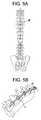
- FIGS. 5 a and 5 bare views of a spinal column after a support rod has been located in the channels of fixation screw assembles, and the channels have been swung from the coronal plane to the sagittal plane, to cause translation of a segment of the spinal column.
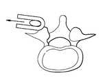
- FIGS. 6 a to 6 dare views along the spinal column of a vertebra, a fixation screw channel and a support rod, showing schematically the translation of the vertebra caused by swinging the fixation screw channel from the coronal plane to the sagittal plane.
- FIGS. 7 a to 7 dare views of a spinal column along the medial lateral axis, showing the use of a pair of tools which can engage the channels of successive fixation screw assemblies to apply a twisting force to successive adjacent vertebrae to correct misalignment.
- FIGS. 1 and 2show a fixation screw assembly 2 which can be used in the technique which is provided by the invention.
- the assemblycomprises a fixation screw 4 which has a head 6 and a threaded shaft 8 .
- the head 6has a bearing surface 10 which forms part of a sphere.
- the head 6has a socket formed in it which can receive the end of a driver tool to enable torsional forces to be applied to the screw to drive it into a bore in a patient's bone. It will often be preferred for the socket to have the shape of a regular polygonal, for example square or hexagonal. Other suitable sockets can be star shaped.
- the configuration of the thread on the shaft 8will be selected according to the nature of the bone into which the screw assembly is to be fixed. The factors which affect the design of bone screws are well understood in the literature.
- the assemblyincludes a channel 11 which comprises a pair of parallel arms 12 , 14 and a base 16 which extends between them.
- the basehas a bore 18 formed in it.
- the boreis sized so that the shaft 8 on the screw 4 can pass through it, but the head 6 cannot.
- the basehas a socket formed in it which has the shape of part of a sphere. Accordingly, the screw can be manipulated relative to the channel when the threaded shaft of the screw extends through the bore, with the spherical surfaces of the screw head and the socket in the base in contact with one another.
- the base 16 of the channelis orientated so that the angles between it and each of the arms 12 , 14 of the channel, when the assembly is viewed from one side along an axis which is perpendicular to the plane which contains the two arms, are not equal. Accordingly, the angle between the bottom face of the base and a line which extends between the arms at their upper ends is non-zero. Preferably, that angle is at least about 5°. Preferably, that angle is not more than about 20°. Accordingly, the screw can be manipulated relative to the channel through a range of angles relative to the channel with the midpoint of the range being angularly offset relative to the axis of the channel (defined by the direction in which the arms extend from the base). The screw head can be locked relative against manipulation relative to the base of the channel by means of a locking device as described in more detail below.
- Each of the arms 12 , 14has an arm extension 20 , 22 provided on it.
- the arm extensionsare formed integrally with their respective arms, for example by machining from a single body.
- a line of weakness 24is provided where each of the arm extensions is connected to its respective arm, allowing each of the arm extensions to be separated from its respective arm.
- Each arm with its respective arm extensionhas a thread formed on its internal surface.
- the threads on the opposed surfaces of the arms and the arm extensionsare continuous so that a screw having a thread on its peripheral surface can engage the threads on the arms and the arm extensions, and be screwed down into the channel.
- the spacing between the arms and their respective arm extensionsis such that a spinal support rod 26 can be received in the channel between the arms.
- the rodcan be formed from titanium or an alloy thereof.
- the rodcan be locked within the channel by means of a locking device as described in more detail below.
- the fixation screw assemblyincludes a sleeve 30 .
- the sleevehas a circular cross-section when viewed from above and has a pair of opposed slots 34 formed in its side walls which can be aligned with the slots in the channel between the opposed arms, so that a support rod 26 extending through the channel between the arms can be accommodated within the sleeve.
- the upper end 36 of the sleeveprovides a flat surface through which an axial force can be applied to the sleeve to drive it axially within the channel.
- the sleeveis sized so that the diameter of the upper end is a sliding fit between the internal surfaces of the channel.
- the lower end 38 of the sleeveis shaped so that it is a close surface to surface fit against the head of the fixation screw, by virtue of matching the spherical shape of the screw head.
- FIG. 3show a fixation screw assembly which includes a rod-receiving channel defined by two arms 112 , 114 with a base (not shown because of this view being a sectional view) extending between them.
- the basehas a bore 118 formed in it.
- the boreextends through a part-spherical socket which is shaped to facilitate relative manipulation between the channel and a fixation screw with a part-spherical head.
- the fixation screw assemblyincludes a locking device which comprises a dual locking screw 50 and a sleeve 52 .
- the sleevehas a circular cross-section when viewed from above and has a pair of opposed slots formed in its side walls which can be aligned with the slots in the channel between the opposed arms, so that a support rod 26 extending through the channel between the arms can be accommodated within the sleeve.
- the upper end 56 of the sleeveprovides a flat surface through which an axial force can be applied to the sleeve to drive it axially within the channel.
- the lower end 58 of the sleeveis shaped so that it is a close surface to surface fit against the head of the fixation screw, by virtue of matching the spherical shape of the screw head.
- the dual locking screw 50comprises an outer screw 60 which has a bore 62 extending though it.
- the outer screwhas a thread formed in its outer surface, which can engage with the thread which is formed on the internal surfaces of the arms 12 , 14 and their respective arm extensions 20 , 22 .
- the outer screwalso has a thread on the internal surface which is defined by the bore in the screw.
- the outer screwhas a plurality of spaced apart recesses in its upper facing surface, for engaging appropriate formations on a tool by which torsional forces can be applied to the outer screw to move it within the channel.
- the dual locking screwfurther includes an inner screw 64 which can engage the thread on the surface of the outer screw within the bore.
- the screwhas a socket 66 which is star shaped to engage an appropriate driver with a star shaped protrusion on it.
- FIG. 3also shows a pair of opposed blind bores 68 in the outer surfaces of the channel side walls 12 , 14 , which can be engaged by means of a double pin gripper tool, to manipulate the channel, for example in translation or by pivoting it relative to the head of the fixation screw.
- the method of the inventioncan be performed using a fixation screw assembly as described above.
- the method of the inventioncan involve one or more of the following steps:
Landscapes
- Health & Medical Sciences (AREA)
- Orthopedic Medicine & Surgery (AREA)
- Life Sciences & Earth Sciences (AREA)
- Surgery (AREA)
- Neurology (AREA)
- Heart & Thoracic Surgery (AREA)
- Engineering & Computer Science (AREA)
- Biomedical Technology (AREA)
- Nuclear Medicine, Radiotherapy & Molecular Imaging (AREA)
- Medical Informatics (AREA)
- Molecular Biology (AREA)
- Animal Behavior & Ethology (AREA)
- General Health & Medical Sciences (AREA)
- Public Health (AREA)
- Veterinary Medicine (AREA)
- Surgical Instruments (AREA)
- Prostheses (AREA)
Abstract
Description
- a. fixing at least two fixation screw assemblies to respective vertebrae in which each fixation screw assembly comprises a fixation screw having a threaded shaft and a head, a channel which comprises a pair of approximately parallel arms and a base which extends between them, and an arm extension provided on each of the channel arms which is configured to be readily detached from the arm. in which:
- b. sliding the rod generally in the coronal plane so that it is positioned between the arm extensions on each of the fixation screws,
- c. swinging the channels relative to the heads of the fixation screws so that the channels become less inclined to the axes of the fixation screws, and so that the rod is located generally posteriorly of the spinal column,
- d. locking the channel against swinging relative to the screw,
- e. rotating the rod about its axis relative to at least one of the channels, and
- f. locking the rod against movement relative to the channel.
- a. a fixation screw having a threaded shaft and a head,
- b. a channel which comprises a pair of approximately parallel arms and a base which extends between them, in which:
- c. a locking device which can be fitted to the channel, and which can separately lock:
- d. an arm extension provided on each of the channel arms at a point on its arm which is further from the base of the channel the point on the arm at which the locking device is fitted to the channel, and which is configured to be readily detached from the arm.
- 1. Preparing the bone to receive the fixation screw, generally by drilling a hole in the bone which is sized appropriately to receive the fixation screw.
- 2. Assembling the fixation screw and the channel, so that the threaded shaft of the screw extends through the bore in the base of the channel, and so that the part-spherical head of the screw is received in the part-spherical socket in the base of the channel.
- 3. Using a driver tool which is fitted with the fixation screw to drive the screw into the prepared hole in the bone.
- 4. Locating the sleeve component of the locking device within the channel, so that the slots in the side walls of the sleeve are aligned with the gaps between the channel arms, and so that the lower surface of the sleeve component is on contact with the spherical surface of the head of the fixation screw.
- 5. Locating a spinal support rod in the channel, so that extends from the channel through the slots in the sleeve component of the locking device and through the gaps between the arms of the channel.
- 6. Engaging a dual locking screw with the threads on the internal surfaces of the arms and the arms extensions of the channel.
- 7. Manipulating the channel using a double pin gripper tool which engages the opposed blind bores in the outer surfaces of the channel side walls, so that the channel is orientated appropriately relative to the fixation screw.
- 8. Applying torsional forces to the outer screw of the dual locking screw to move it within the channel using a tool which can engage the spaced apart recesses in the upper facing surface of the outer screw, so as to force the sleeve component to grip tightly the part spherical surface of the head of the fixation screw.
- 9. Applying torsional forces to the inner screw of the dual locking screw to move it relative to the outer locking screw so that it contacts the spinal support rod and fixes the rod relative to the channel and to the fixation screw.
- 1. Fixing at least two fixation screw assemblies, of the kind describe above with reference to
FIGS. 1 to 3 , to respective vertebrae of a spinal column of a patient requiring treatment of scoliosis, with the fixation screw oriented so that it extends into the pedicle, and so that the channel is orientated so that the arms thereof extend approximately in the coronal plane. - 2. Locating a spinal support rod between the arm extensions of each of the fixation screw assemblies so that the support rod is located generally medially or generally laterally of the spinal column, in which the spinal support rod is curved along its length, so that the curvature matches (a) the shape of the deformed spine when the rod is placed alongside the spine and viewed along the anterior posterior axis, and also (b) the shape of the corrected spine when the rod is placed alongside the spine and viewed along the medial lateral axis.
- 3. Using dual locking screws within the channels of the fixation screw assemblies to retain the spinal support rod loosely between the arm extensions, as shown in
FIGS. 4 aand4b. - 4. Swinging the channels relative to the heads of the fixation screws so that the channels become closer to being aligned with the sagittal plane and the support rod becomes located generally posteriorly of the spinal column, as shown in
FIGS. 5 aand5b. In this step of the method, deformation of the spinal column can be corrected by a translation of adjacent vertebrae in one or more segments of the spinal column, as shown inFIGS. 6 ato6d. - 5. Using the outer screw part of each of the dual locking screws to lock each channel against movement relative to the head of its respective fixation screw.
- 6. Locking the rod against movement relative to selected ones of the channels, in many cases preferentially the channels which are located towards the ends of the rod, using the inner screw part of the dual locking screws.
- 7. Applying a twisting force to a vertebra by gripping the channels of the fixation screw assembly which is fixed to that vertebra, so that the vertebra is twisted relative to the spinal support rod, and then locking the channel against rotation relative to the rod using the inner screw part of the dual locking screw. In this step of the method, deformation of the spinal column can be corrected by rotating adjacent vertebrae in one or more segments of the spinal column. This step can be repeated as required sequentially to one or more of the vertebrae, generally successively to adjacent vertebrae along the spinal column, as shown in
FIGS. 7 ato7d. The channels of the fixation screw assembly can be gripped using a tool which comprises a socket having a circular cross-section and a circular core, in which a channel can be received in the annular space between the core and the socket wall. - 8. Ensuring that the rod is locked against movement relative to each channel using the inner screw part of the dual locking screws.
- 9. Separating the arm extensions from the arms of the channels of the fixation screw assemblies.
- 1. Fixing at least two fixation screw assemblies, of the kind describe above with reference to
- 1. The channels of the fixation screw assemblies can be moved between a position in which the arms lie in the sagittal plane and a position in which the arms lie in the coronal plane, by virtue of the midpoint of the range of angles through which the channel can be moved relative to the fixation screw being offset.
- 2. The arm extensions on the channels of the fixation screw assemblies allow a spinal support rod to be located within the channels loosely without excessive deformation of the rod when first located there, especially when the channels of the fixation screw assemblies lie approximately in the coronal plane.
- 3. The use of a dual screw locking device allows separate locking of the channel against swinging relative to the head of the screw, and the rod against movement in the channel. This can facilitate the performance of separate steps of the method in which deformation is corrected by application of translational forces and rotational forces respectively.
Claims (16)
Priority Applications (5)
| Application Number | Priority Date | Filing Date | Title |
|---|---|---|---|
| US12/365,225US8007522B2 (en) | 2008-02-04 | 2009-02-04 | Methods for correction of spinal deformities |
| US13/205,248US8556941B2 (en) | 2008-02-04 | 2011-08-08 | Methods for correction of spinal deformities |
| US14/029,037US9713488B2 (en) | 2008-02-04 | 2013-09-17 | Methods for correction of spinal deformities |
| US15/629,825US10201377B2 (en) | 2008-02-04 | 2017-06-22 | Methods for correction of spinal deformities |
| US16/271,607US10987145B2 (en) | 2008-02-04 | 2019-02-08 | Methods for correction of spinal deformities |
Applications Claiming Priority (2)
| Application Number | Priority Date | Filing Date | Title |
|---|---|---|---|
| US2604808P | 2008-02-04 | 2008-02-04 | |
| US12/365,225US8007522B2 (en) | 2008-02-04 | 2009-02-04 | Methods for correction of spinal deformities |
Related Child Applications (1)
| Application Number | Title | Priority Date | Filing Date |
|---|---|---|---|
| US13/205,248ContinuationUS8556941B2 (en) | 2008-02-04 | 2011-08-08 | Methods for correction of spinal deformities |
Publications (2)
| Publication Number | Publication Date |
|---|---|
| US20090216280A1 US20090216280A1 (en) | 2009-08-27 |
| US8007522B2true US8007522B2 (en) | 2011-08-30 |
Family
ID=40999052
Family Applications (5)
| Application Number | Title | Priority Date | Filing Date |
|---|---|---|---|
| US12/365,225Active2030-03-06US8007522B2 (en) | 2008-02-04 | 2009-02-04 | Methods for correction of spinal deformities |
| US13/205,248Active2029-06-08US8556941B2 (en) | 2008-02-04 | 2011-08-08 | Methods for correction of spinal deformities |
| US14/029,037ActiveUS9713488B2 (en) | 2008-02-04 | 2013-09-17 | Methods for correction of spinal deformities |
| US15/629,825Active2029-03-09US10201377B2 (en) | 2008-02-04 | 2017-06-22 | Methods for correction of spinal deformities |
| US16/271,607Active2029-08-03US10987145B2 (en) | 2008-02-04 | 2019-02-08 | Methods for correction of spinal deformities |
Family Applications After (4)
| Application Number | Title | Priority Date | Filing Date |
|---|---|---|---|
| US13/205,248Active2029-06-08US8556941B2 (en) | 2008-02-04 | 2011-08-08 | Methods for correction of spinal deformities |
| US14/029,037ActiveUS9713488B2 (en) | 2008-02-04 | 2013-09-17 | Methods for correction of spinal deformities |
| US15/629,825Active2029-03-09US10201377B2 (en) | 2008-02-04 | 2017-06-22 | Methods for correction of spinal deformities |
| US16/271,607Active2029-08-03US10987145B2 (en) | 2008-02-04 | 2019-02-08 | Methods for correction of spinal deformities |
Country Status (1)
| Country | Link |
|---|---|
| US (5) | US8007522B2 (en) |
Cited By (20)
| Publication number | Priority date | Publication date | Assignee | Title |
|---|---|---|---|---|
| US20110295321A1 (en)* | 2008-02-04 | 2011-12-01 | John Hutchinson | Methods for Correction of Spinal Deformities |
| US8337532B1 (en)* | 2011-12-08 | 2012-12-25 | Spine Wave, Inc. | Methods for percutaneously extending an existing spinal construct |
| US8986349B1 (en) | 2009-11-11 | 2015-03-24 | Nuvasive, Inc. | Systems and methods for correcting spinal deformities |
| US9050141B2 (en) | 2008-02-02 | 2015-06-09 | Texas Scottish Rite Hospital For Children | Pedicle screw |
| US9186484B2 (en) | 2010-07-01 | 2015-11-17 | DePuy Synthes Products, Inc. | Guidewire insertion methods and devices |
| US9259247B2 (en) | 2013-03-14 | 2016-02-16 | Medos International Sarl | Locking compression members for use with bone anchor assemblies and methods |
| US9289249B2 (en) | 2013-03-14 | 2016-03-22 | DePuy Synthes Products, Inc. | Bone anchors and surgical instruments with integrated guide tips |
| US9345517B2 (en) | 2008-02-02 | 2016-05-24 | Globus Medical, Inc. | Pedicle screw having a removable rod coupling |
| US9408641B2 (en) | 2008-02-02 | 2016-08-09 | Globus Medical, Inc. | Spinal rod link reducer |
| US9498254B2 (en) | 2013-03-14 | 2016-11-22 | Medos International Sarl | Bottom-loading bone anchor assemblies |
| US9579126B2 (en) | 2008-02-02 | 2017-02-28 | Globus Medical, Inc. | Spinal rod link reducer |
| US9717531B2 (en) | 2013-10-18 | 2017-08-01 | Warsaw Orthopedic, Inc. | Spinal correction method and system |
| US9724145B2 (en) | 2013-03-14 | 2017-08-08 | Medos International Sarl | Bone anchor assemblies with multiple component bottom loading bone anchors |
| US9775660B2 (en) | 2013-03-14 | 2017-10-03 | DePuy Synthes Products, Inc. | Bottom-loading bone anchor assemblies and methods |
| US9782204B2 (en) | 2012-09-28 | 2017-10-10 | Medos International Sarl | Bone anchor assemblies |
| US9918747B2 (en) | 2013-03-14 | 2018-03-20 | DePuy Synthes Products, Inc. | Bone anchor assemblies and methods with improved locking |
| US10342582B2 (en) | 2013-03-14 | 2019-07-09 | DePuy Synthes Products, Inc. | Bone anchor assemblies and methods with improved locking |
| US10603077B2 (en) | 2007-04-12 | 2020-03-31 | Globus Medical, Inc. | Orthopedic fastener for stabilization and fixation |
| US10765466B2 (en)* | 2014-12-15 | 2020-09-08 | Medos International Sarl | Bone anchor driver and methods |
| US12127766B2 (en) | 2021-03-05 | 2024-10-29 | Medos International Sàrl | Selectively locking polyaxial screw |
Families Citing this family (66)
| Publication number | Priority date | Publication date | Assignee | Title |
|---|---|---|---|---|
| US7833250B2 (en) | 2004-11-10 | 2010-11-16 | Jackson Roger P | Polyaxial bone screw with helically wound capture connection |
| US7862587B2 (en) | 2004-02-27 | 2011-01-04 | Jackson Roger P | Dynamic stabilization assemblies, tool set and method |
| US8876868B2 (en) | 2002-09-06 | 2014-11-04 | Roger P. Jackson | Helical guide and advancement flange with radially loaded lip |
| WO2006052796A2 (en) | 2004-11-10 | 2006-05-18 | Jackson Roger P | Helical guide and advancement flange with break-off extensions |
| US7621918B2 (en) | 2004-11-23 | 2009-11-24 | Jackson Roger P | Spinal fixation tool set and method |
| US7377923B2 (en) | 2003-05-22 | 2008-05-27 | Alphatec Spine, Inc. | Variable angle spinal screw assembly |
| US8377102B2 (en) | 2003-06-18 | 2013-02-19 | Roger P. Jackson | Polyaxial bone anchor with spline capture connection and lower pressure insert |
| US8398682B2 (en) | 2003-06-18 | 2013-03-19 | Roger P. Jackson | Polyaxial bone screw assembly |
| US7766915B2 (en) | 2004-02-27 | 2010-08-03 | Jackson Roger P | Dynamic fixation assemblies with inner core and outer coil-like member |
| US8926670B2 (en) | 2003-06-18 | 2015-01-06 | Roger P. Jackson | Polyaxial bone screw assembly |
| US8137386B2 (en) | 2003-08-28 | 2012-03-20 | Jackson Roger P | Polyaxial bone screw apparatus |
| US7776067B2 (en) | 2005-05-27 | 2010-08-17 | Jackson Roger P | Polyaxial bone screw with shank articulation pressure insert and method |
| US7527638B2 (en) | 2003-12-16 | 2009-05-05 | Depuy Spine, Inc. | Methods and devices for minimally invasive spinal fixation element placement |
| US11419642B2 (en) | 2003-12-16 | 2022-08-23 | Medos International Sarl | Percutaneous access devices and bone anchor assemblies |
| US7179261B2 (en) | 2003-12-16 | 2007-02-20 | Depuy Spine, Inc. | Percutaneous access devices and bone anchor assemblies |
| US8152810B2 (en) | 2004-11-23 | 2012-04-10 | Jackson Roger P | Spinal fixation tool set and method |
| US7160300B2 (en) | 2004-02-27 | 2007-01-09 | Jackson Roger P | Orthopedic implant rod reduction tool set and method |
| JP2007525274A (en) | 2004-02-27 | 2007-09-06 | ロジャー・ピー・ジャクソン | Orthopedic implant rod reduction instrument set and method |
| US11241261B2 (en) | 2005-09-30 | 2022-02-08 | Roger P Jackson | Apparatus and method for soft spinal stabilization using a tensionable cord and releasable end structure |
| US8926672B2 (en) | 2004-11-10 | 2015-01-06 | Roger P. Jackson | Splay control closure for open bone anchor |
| US9168069B2 (en) | 2009-06-15 | 2015-10-27 | Roger P. Jackson | Polyaxial bone anchor with pop-on shank and winged insert with lower skirt for engaging a friction fit retainer |
| US9980753B2 (en) | 2009-06-15 | 2018-05-29 | Roger P Jackson | pivotal anchor with snap-in-place insert having rotation blocking extensions |
| US8444681B2 (en) | 2009-06-15 | 2013-05-21 | Roger P. Jackson | Polyaxial bone anchor with pop-on shank, friction fit retainer and winged insert |
| US8308782B2 (en) | 2004-11-23 | 2012-11-13 | Jackson Roger P | Bone anchors with longitudinal connecting member engaging inserts and closures for fixation and optional angulation |
| WO2006057837A1 (en) | 2004-11-23 | 2006-06-01 | Jackson Roger P | Spinal fixation tool attachment structure |
| US10076361B2 (en) | 2005-02-22 | 2018-09-18 | Roger P. Jackson | Polyaxial bone screw with spherical capture, compression and alignment and retention structures |
| US7901437B2 (en) | 2007-01-26 | 2011-03-08 | Jackson Roger P | Dynamic stabilization member with molded connection |
| CA2670988C (en) | 2006-12-08 | 2014-03-25 | Roger P. Jackson | Tool system for dynamic spinal implants |
| US10792074B2 (en) | 2007-01-22 | 2020-10-06 | Roger P. Jackson | Pivotal bone anchor assemly with twist-in-place friction fit insert |
| US8979904B2 (en) | 2007-05-01 | 2015-03-17 | Roger P Jackson | Connecting member with tensioned cord, low profile rigid sleeve and spacer with torsion control |
| AU2010260521C1 (en) | 2008-08-01 | 2013-08-01 | Roger P. Jackson | Longitudinal connecting member with sleeved tensioned cords |
| US9668771B2 (en) | 2009-06-15 | 2017-06-06 | Roger P Jackson | Soft stabilization assemblies with off-set connector |
| CN103826560A (en) | 2009-06-15 | 2014-05-28 | 罗杰.P.杰克逊 | Polyaxial Bone Anchor with Socket Stem and Winged Inserts with Friction Fit Compression Collars |
| US11229457B2 (en) | 2009-06-15 | 2022-01-25 | Roger P. Jackson | Pivotal bone anchor assembly with insert tool deployment |
| US8998959B2 (en) | 2009-06-15 | 2015-04-07 | Roger P Jackson | Polyaxial bone anchors with pop-on shank, fully constrained friction fit retainer and lock and release insert |
| EP2485654B1 (en) | 2009-10-05 | 2021-05-05 | Jackson P. Roger | Polyaxial bone anchor with non-pivotable retainer and pop-on shank, some with friction fit |
| WO2011106339A1 (en)* | 2010-02-23 | 2011-09-01 | K2M, Inc. | Polyaxial bone screw assembly |
| US12383311B2 (en) | 2010-05-14 | 2025-08-12 | Roger P. Jackson | Pivotal bone anchor assembly and method for use thereof |
| AU2011324058A1 (en) | 2010-11-02 | 2013-06-20 | Roger P. Jackson | Polyaxial bone anchor with pop-on shank and pivotable retainer |
| US8337530B2 (en)* | 2011-03-09 | 2012-12-25 | Zimmer Spine, Inc. | Polyaxial pedicle screw with increased angulation |
| JP5865479B2 (en) | 2011-03-24 | 2016-02-17 | ロジャー・ピー・ジャクソン | Multiaxial bone anchor with compound joint and pop-mounted shank |
| US9993269B2 (en)* | 2011-07-15 | 2018-06-12 | Globus Medical, Inc. | Orthopedic fixation devices and methods of installation thereof |
| US9655655B2 (en) | 2011-08-16 | 2017-05-23 | Aesculap Implant Systems, Llc | Two step locking screw assembly |
| EP2559389B1 (en)* | 2011-08-18 | 2013-04-03 | Biedermann Technologies GmbH & Co. KG | Polyaxial bone anchoring device |
| EP2604204B1 (en)* | 2011-12-13 | 2014-10-01 | Biedermann Technologies GmbH & Co. KG | Monoplanar bone anchoring device with selectable pivot plane |
| EP2606841B1 (en)* | 2011-12-23 | 2016-03-09 | Biedermann Technologies GmbH & Co. KG | Polyaxial bone anchoring device |
| US8911479B2 (en) | 2012-01-10 | 2014-12-16 | Roger P. Jackson | Multi-start closures for open implants |
| EP2687171B1 (en) | 2012-07-18 | 2015-04-22 | Biedermann Technologies GmbH & Co. KG | Polyaxial bone anchoring device |
| US9295488B2 (en) | 2012-08-09 | 2016-03-29 | Wilson T. Asfora | Joint fusion |
| US8911478B2 (en) | 2012-11-21 | 2014-12-16 | Roger P. Jackson | Splay control closure for open bone anchor |
| US10058354B2 (en) | 2013-01-28 | 2018-08-28 | Roger P. Jackson | Pivotal bone anchor assembly with frictional shank head seating surfaces |
| US8852239B2 (en) | 2013-02-15 | 2014-10-07 | Roger P Jackson | Sagittal angle screw with integral shank and receiver |
| US20140336709A1 (en)* | 2013-03-13 | 2014-11-13 | Baxano Surgical, Inc. | Multi-threaded pedicle screw system |
| US9566092B2 (en) | 2013-10-29 | 2017-02-14 | Roger P. Jackson | Cervical bone anchor with collet retainer and outer locking sleeve |
| US9717533B2 (en) | 2013-12-12 | 2017-08-01 | Roger P. Jackson | Bone anchor closure pivot-splay control flange form guide and advancement structure |
| US9451993B2 (en) | 2014-01-09 | 2016-09-27 | Roger P. Jackson | Bi-radial pop-on cervical bone anchor |
| US10064658B2 (en) | 2014-06-04 | 2018-09-04 | Roger P. Jackson | Polyaxial bone anchor with insert guides |
| US9597119B2 (en) | 2014-06-04 | 2017-03-21 | Roger P. Jackson | Polyaxial bone anchor with polymer sleeve |
| DE102015109481A1 (en)* | 2015-06-15 | 2016-12-15 | Aesculap Ag | Pedicle screw with radially offset guide |
| US9968378B1 (en)* | 2015-07-22 | 2018-05-15 | University Of South Florida | Adaptation sphere saddle |
| US10130395B2 (en)* | 2015-08-17 | 2018-11-20 | Globus Medical, Inc. | Modular uniplanar pedicle screw assembly for use with a polyaxial bone fastener |
| US20190053833A1 (en)* | 2015-10-09 | 2019-02-21 | LinkSPINE, Inc. | Spinal multi-level facet joint stabilization system |
| US9439692B1 (en)* | 2015-10-09 | 2016-09-13 | Spine Wave, Inc. | Minimally invasive spinal fixation system and method therefor |
| EP3376987B1 (en)* | 2015-11-19 | 2020-10-28 | EOS Imaging | Method of preoperative planning to correct spine misalignment of a patient |
| US11147453B2 (en) | 2017-10-03 | 2021-10-19 | Canon U.S.A., Inc. | Calibration for OCT-NIRAF multimodality probe |
| US11972561B2 (en) | 2020-08-06 | 2024-04-30 | Canon U.S.A., Inc. | Auto-pullback triggering method for intracoronary imaging apparatuses or systems using blood clearing |
Citations (52)
| Publication number | Priority date | Publication date | Assignee | Title |
|---|---|---|---|---|
| EP0470660A1 (en) | 1990-08-07 | 1992-02-12 | Acromed B.V. | Apparatus for the correction of scoliosis |
| US5129388A (en) | 1989-02-09 | 1992-07-14 | Vignaud Jean Louis | Device for supporting the spinal column |
| US5154719A (en) | 1990-02-19 | 1992-10-13 | Societe De Fabrication De Materiel Orthopedique - Sofamor | Implant for a device for osteosynthesis, in particular of the spine |
| US5385565A (en)* | 1992-09-21 | 1995-01-31 | Danek Medical, Inc. | Tool and method for derotating scoliotic spine |
| US5443467A (en) | 1993-03-10 | 1995-08-22 | Biedermann Motech Gmbh | Bone screw |
| US5520689A (en) | 1992-06-04 | 1996-05-28 | Synthes (U.S.A.) | Osteosynthetic fastening device |
| US5672176A (en) | 1995-03-15 | 1997-09-30 | Biedermann; Lutz | Anchoring member |
| US5989250A (en)* | 1996-10-24 | 1999-11-23 | Spinal Concepts, Inc. | Method and apparatus for spinal fixation |
| US6113601A (en) | 1998-06-12 | 2000-09-05 | Bones Consulting, Llc | Polyaxial pedicle screw having a loosely coupled locking cap |
| US6224598B1 (en) | 2000-02-16 | 2001-05-01 | Roger P. Jackson | Bone screw threaded plug closure with central set screw |
| US6251112B1 (en) | 2000-04-18 | 2001-06-26 | Roger P. Jackson | Thin profile closure cap for open ended medical implant |
| US6258090B1 (en) | 2000-04-28 | 2001-07-10 | Roger P. Jackson | Closure for open ended medical implant and removal tool |
| US6261287B1 (en) | 1992-03-02 | 2001-07-17 | Stryker Trauma Gmbh | Apparatus for bracing vertebrae |
| US6296642B1 (en) | 1998-11-09 | 2001-10-02 | Sdgi Holdings, Inc. | Reverse angle thread for preventing splaying in medical devices |
| US6355038B1 (en) | 1998-09-25 | 2002-03-12 | Perumala Corporation | Multi-axis internal spinal fixation |
| US6379356B1 (en) | 2000-04-26 | 2002-04-30 | Roger P. Jackson | Closure for open ended medical implant |
| US6440132B1 (en) | 2000-05-24 | 2002-08-27 | Roger P. Jackson | Open head bone screw closure with threaded boss |
| US20020133159A1 (en) | 2000-12-08 | 2002-09-19 | Jackson Roger P. | Closure for open-headed medical implant |
| US6454768B1 (en) | 2000-12-05 | 2002-09-24 | Roger P. Jackson | Removable gripping set screw |
| US6454772B1 (en) | 2000-12-08 | 2002-09-24 | Roger P. Jackson | Set screw for medical implant with gripping side slots |
| US6458132B2 (en) | 2000-03-15 | 2002-10-01 | Gil-Woon Choi | Spine supporting system |
| US6485494B1 (en) | 1996-12-20 | 2002-11-26 | Thomas T. Haider | Pedicle screw system for osteosynthesis |
| US20030055426A1 (en) | 2001-09-14 | 2003-03-20 | John Carbone | Biased angulation bone fixation assembly |
| EP1295566A1 (en) | 1999-06-30 | 2003-03-26 | Surgival Co., S.A. | Polyaxial vertebral fixing system |
| US6540748B2 (en) | 1999-09-27 | 2003-04-01 | Blackstone Medical, Inc. | Surgical screw system and method of use |
| US20030125741A1 (en)* | 2001-12-28 | 2003-07-03 | Biedermann Motech Gmbh | Locking device for securing a rod-shaped element in a holding element connected to a shank |
| US6723100B2 (en) | 2001-07-27 | 2004-04-20 | Biedermann Motech Gmbh | Bone screw and fastening tool for same |
| US6726687B2 (en) | 2000-12-08 | 2004-04-27 | Jackson Roger P | Closure plug for open-headed medical implant |
| US6730089B2 (en) | 2002-08-26 | 2004-05-04 | Roger P. Jackson | Nested closure plug and set screw with break-off heads |
| US6736820B2 (en) | 2000-11-10 | 2004-05-18 | Biedermann Motech Gmbh | Bone screw |
| US6740086B2 (en) | 2002-04-18 | 2004-05-25 | Spinal Innovations, Llc | Screw and rod fixation assembly and device |
| US20040162560A1 (en) | 2003-02-19 | 2004-08-19 | Raynor Donald E. | Implant device including threaded locking mechanism |
| US20040186473A1 (en) | 2003-03-21 | 2004-09-23 | Cournoyer John R. | Spinal fixation devices of improved strength and rigidity |
| US6835196B2 (en) | 2001-03-27 | 2004-12-28 | Biedermann Motech Gmbh | Anchoring element |
| US6869433B2 (en) | 2001-01-12 | 2005-03-22 | Depuy Acromed, Inc. | Polyaxial screw with improved locking |
| US20050080415A1 (en) | 2003-10-14 | 2005-04-14 | Keyer Thomas R. | Polyaxial bone anchor and method of spinal fixation |
| US6884244B1 (en) | 2000-06-06 | 2005-04-26 | Roger P. Jackson | Removable medical implant closure for open headed implants |
| US20050154391A1 (en) | 2003-12-30 | 2005-07-14 | Thomas Doherty | Bone anchor assemblies |
| US20050154393A1 (en) | 2003-12-30 | 2005-07-14 | Thomas Doherty | Bone anchor assemblies and methods of manufacturing bone anchor assemblies |
| US20050153077A1 (en) | 2003-12-03 | 2005-07-14 | Anthony Gedeon | Method of resisting contaminant build up and oxidation of vehicle surfaces and other surfaces |
| US20050187548A1 (en)* | 2004-01-13 | 2005-08-25 | Butler Michael S. | Pedicle screw constructs for spine fixation systems |
| US6997927B2 (en) | 2000-12-08 | 2006-02-14 | Jackson Roger P | closure for rod receiving orthopedic implant having a pair of spaced apertures for removal |
| US7018378B2 (en) | 2000-12-27 | 2006-03-28 | Biedermann Motech Gmbh | Screw |
| EP1774919A1 (en) | 2005-10-12 | 2007-04-18 | BIEDERMANN MOTECH GmbH | Poly-axial screw pivotable in a single plane |
| US7223268B2 (en) | 2001-11-27 | 2007-05-29 | Biedermann Mötech GmbH | Locking device for securing a rod-shaped element in a holding element connected to a shank |
| US20070123870A1 (en) | 2005-07-18 | 2007-05-31 | Jeon Dong M | Bi-polar screw assembly |
| EP1795134A1 (en) | 2005-11-17 | 2007-06-13 | BIEDERMANN MOTECH GmbH | Polyaxial screw for flexible rod |
| US7264621B2 (en) | 2004-06-17 | 2007-09-04 | Sdgi Holdings, Inc. | Multi-axial bone attachment assembly |
| US20070265621A1 (en) | 2006-04-06 | 2007-11-15 | Wilfried Matthis | Bone anchoring device |
| US20080269805A1 (en)* | 2007-04-25 | 2008-10-30 | Warsaw Orthopedic, Inc. | Methods for correcting spinal deformities |
| US20090228051A1 (en) | 2008-03-10 | 2009-09-10 | Eric Kolb | Bilateral vertebral body derotation system |
| US7731736B2 (en)* | 2004-06-14 | 2010-06-08 | Zimmer Spine, Inc. | Fastening system for spinal stabilization system |
Family Cites Families (247)
| Publication number | Priority date | Publication date | Assignee | Title |
|---|---|---|---|---|
| BE469107A (en) | 1945-01-25 | |||
| US2842180A (en) | 1950-02-23 | 1958-07-08 | Set Screw & Mfg Company | Self-locking threads with locking interference fit |
| US2788045A (en) | 1952-10-06 | 1957-04-09 | Rosan Joseph | Conventional truncated screw threads with small locking thread bonded therebetween |
| US4124318A (en) | 1978-03-23 | 1978-11-07 | General Motors Corporation | Splined assembly with retaining rings |
| US4762024A (en) | 1985-07-30 | 1988-08-09 | Dana Corporation | Shaft retaining means for a differential gear assembly |
| US5009017A (en) | 1987-01-20 | 1991-04-23 | Caterpillar Inc. | Retaining pin having a positive keeper means |
| WO1991016020A1 (en) | 1990-04-26 | 1991-10-31 | Danninger Medical Technology, Inc. | Transpedicular screw system and method of use |
| US5102412A (en)* | 1990-06-19 | 1992-04-07 | Chaim Rogozinski | System for instrumentation of the spine in the treatment of spinal deformities |
| JP3308271B2 (en) | 1992-06-25 | 2002-07-29 | ジンテーズ アクチエンゲゼルシャフト,クール | Osteosynthesis fixation device |
| US5306275A (en) | 1992-12-31 | 1994-04-26 | Bryan Donald W | Lumbar spine fixation apparatus and method |
| FR2702362B3 (en) | 1993-02-24 | 1995-04-14 | Soprane Sa | Fixator for osteosynthesis of the lumbosacral spine. |
| US5487744A (en) | 1993-04-08 | 1996-01-30 | Advanced Spine Fixation Systems, Inc. | Closed connector for spinal fixation systems |
| US6077262A (en) | 1993-06-04 | 2000-06-20 | Synthes (U.S.A.) | Posterior spinal implant |
| US5580246A (en) | 1995-01-30 | 1996-12-03 | Fried; Paula S. | Dental implants and methods for extending service life |
| US5643260A (en) | 1995-02-14 | 1997-07-01 | Smith & Nephew, Inc. | Orthopedic fixation system |
| US5562661A (en) | 1995-03-16 | 1996-10-08 | Alphatec Manufacturing Incorporated | Top tightening bone fixation apparatus |
| FR2750595B1 (en) | 1996-07-02 | 1998-12-04 | Dev Sed Soc Et | MEDICAL SCREWS ESPECIALLY FOR SURGERY AND ANCILLARY OF POSITION |
| US5879350A (en) | 1996-09-24 | 1999-03-09 | Sdgi Holdings, Inc. | Multi-axial bone screw assembly |
| US5797911A (en) | 1996-09-24 | 1998-08-25 | Sdgi Holdings, Inc. | Multi-axial bone screw assembly |
| US5885286A (en) | 1996-09-24 | 1999-03-23 | Sdgi Holdings, Inc. | Multi-axial bone screw assembly |
| US6224596B1 (en) | 1997-01-06 | 2001-05-01 | Roger P. Jackson | Set screw for use with osteosynthesis apparatus |
| US6371957B1 (en) | 1997-01-22 | 2002-04-16 | Synthes (Usa) | Device for connecting a longitudinal bar to a pedicle screw |
| FR2759282B1 (en) | 1997-02-10 | 1999-05-07 | Eos Medical | BREAKABLE SCREW DEVICE FOR OSTEOSYNTHESIS PLATE OR FOR COAPTATION OF TWO BONE FRAGMENTS |
| BR9809079A (en) | 1997-04-09 | 2002-01-15 | Implant Innovations Inc | Implant delivery system |
| EP1444964B1 (en) | 1997-05-24 | 2007-01-10 | Straumann Holding AG | Support for sustaining and/or forming a dental prosthesis |
| DE29710484U1 (en) | 1997-06-16 | 1998-10-15 | Howmedica GmbH, 24232 Schönkirchen | Receiving part for a holding component of a spinal implant |
| EP0933065A1 (en) | 1998-02-02 | 1999-08-04 | Sulzer Orthopädie AG | Pivotable attachment system for a bone screw |
| US6068632A (en) | 1998-05-12 | 2000-05-30 | Carchidi; Joseph Edward | Bone tap apparatus |
| US6090111A (en) | 1998-06-17 | 2000-07-18 | Surgical Dynamics, Inc. | Device for securing spinal rods |
| US6056753A (en) | 1998-07-13 | 2000-05-02 | Jackson; Roger P. | Set screw for use with osteosynthesis apparatus |
| US6050997A (en) | 1999-01-25 | 2000-04-18 | Mullane; Thomas S. | Spinal fixation system |
| DE29903342U1 (en) | 1999-02-24 | 1999-06-02 | Grzibek, Egbert, 97534 Waigolshausen | Fixing element for holding elements of spinal implants |
| US6402757B1 (en) | 1999-03-12 | 2002-06-11 | Biomet, Inc. | Cannulated fastener system for repair of bone fracture |
| US6302888B1 (en) | 1999-03-19 | 2001-10-16 | Interpore Cross International | Locking dovetail and self-limiting set screw assembly for a spinal stabilization member |
| US6280442B1 (en) | 1999-09-01 | 2001-08-28 | Sdgi Holdings, Inc. | Multi-axial bone screw assembly |
| DE60026136T2 (en) | 1999-11-15 | 2006-11-23 | Arthrex Inc., Naples | Rejuvenating bioabsorbing interference screw for the osteal attachment of ligaments |
| DE59901090D1 (en) | 1999-12-23 | 2002-05-02 | Storz Karl Gmbh & Co Kg | Decentralized drive screw |
| EP1292239B1 (en) | 2000-06-23 | 2013-02-13 | University Of Southern California | Percutaneous vertebral fusion system |
| FR2810874B1 (en) | 2000-06-30 | 2002-08-23 | Materiel Orthopedique En Abreg | IMPLANT FOR OSTEOSYNTHESIS DEVICE COMPRISING A PART FOR BONE ANCHORING AND A BODY FOR FIXING ON A ROD |
| US7833250B2 (en) | 2004-11-10 | 2010-11-16 | Jackson Roger P | Polyaxial bone screw with helically wound capture connection |
| US20060083603A1 (en) | 2000-08-23 | 2006-04-20 | Jackson Roger P | Reverse angled threadform with anti-splay clearance |
| US20060025771A1 (en) | 2000-08-23 | 2006-02-02 | Jackson Roger P | Helical reverse angle guide and advancement structure with break-off extensions |
| US6485491B1 (en) | 2000-09-15 | 2002-11-26 | Sdgi Holdings, Inc. | Posterior fixation system |
| US6488681B2 (en)* | 2001-01-05 | 2002-12-03 | Stryker Spine S.A. | Pedicle screw assembly |
| US6663656B2 (en) | 2001-02-26 | 2003-12-16 | Arthrex, Inc. | Torque driver for interference screw |
| WO2002076317A1 (en) | 2001-03-27 | 2002-10-03 | Ferree Bret A | Hinged anterior thoracic/lumbar plate |
| US8353932B2 (en) | 2005-09-30 | 2013-01-15 | Jackson Roger P | Polyaxial bone anchor assembly with one-piece closure, pressure insert and plastic elongate member |
| US8292926B2 (en) | 2005-09-30 | 2012-10-23 | Jackson Roger P | Dynamic stabilization connecting member with elastic core and outer sleeve |
| US6623485B2 (en) | 2001-10-17 | 2003-09-23 | Hammill Manufacturing Company | Split ring bone screw for a spinal fixation system |
| DE10157969C1 (en) | 2001-11-27 | 2003-02-06 | Biedermann Motech Gmbh | Element used in spinal and accident surgery comprises a shaft joined to a holding element having a U-shaped recess with two free arms having an internal thread with flanks lying at right angles to the central axis of the holding element |
| FR2833151B1 (en) | 2001-12-12 | 2004-09-17 | Ldr Medical | BONE ANCHORING IMPLANT WITH POLYAXIAL HEAD |
| US7066937B2 (en) | 2002-02-13 | 2006-06-27 | Endius Incorporated | Apparatus for connecting a longitudinal member to a bone portion |
| US7842073B2 (en) | 2002-04-18 | 2010-11-30 | Aesculap Ii, Inc. | Screw and rod fixation assembly and device |
| WO2003096916A1 (en) | 2002-05-21 | 2003-11-27 | Peter Metz-Stavenhagen | Anchoring element for securing a rod on a vertebra |
| DE10236691B4 (en)* | 2002-08-09 | 2005-12-01 | Biedermann Motech Gmbh | Dynamic stabilization device for bones, in particular for vertebrae |
| DE10246177A1 (en) | 2002-10-02 | 2004-04-22 | Biedermann Motech Gmbh | Anchor element consists of screw with head, bone-thread section on shank and holder joining rod-shaped part to screw. with cavities in wall, and thread-free end of shank |
| US8162989B2 (en) | 2002-11-04 | 2012-04-24 | Altus Partners, Llc | Orthopedic rod system |
| WO2004058081A1 (en) | 2002-12-20 | 2004-07-15 | High Plains Technology Group, Llc | Bone screw fastener and apparatus for inserting and removing same |
| US6755836B1 (en) | 2002-12-20 | 2004-06-29 | High Plains Technology Group, Llc | Bone screw fastener and apparatus for inserting and removing same |
| US20060200128A1 (en)* | 2003-04-04 | 2006-09-07 | Richard Mueller | Bone anchor |
| US6716214B1 (en) | 2003-06-18 | 2004-04-06 | Roger P. Jackson | Polyaxial bone screw with spline capture connection |
| US7473267B2 (en) | 2003-04-25 | 2009-01-06 | Warsaw Orthopedic, Inc. | System and method for minimally invasive posterior fixation |
| US7615068B2 (en) | 2003-05-02 | 2009-11-10 | Applied Spine Technologies, Inc. | Mounting mechanisms for pedicle screws and related assemblies |
| US8652175B2 (en) | 2003-05-02 | 2014-02-18 | Rachiotek, Llc | Surgical implant devices and systems including a sheath member |
| US20050182401A1 (en) | 2003-05-02 | 2005-08-18 | Timm Jens P. | Systems and methods for spine stabilization including a dynamic junction |
| FR2855392B1 (en) | 2003-05-28 | 2005-08-05 | Spinevision | CONNECTION DEVICE FOR SPINAL OSTESYNTHESIS |
| US7670362B2 (en) | 2003-06-13 | 2010-03-02 | Tyco Healthcare Group Lp | Multiple member interconnect for surgical instrument and absorbable screw fastener |
| US7967850B2 (en) | 2003-06-18 | 2011-06-28 | Jackson Roger P | Polyaxial bone anchor with helical capture connection, insert and dual locking assembly |
| US7766915B2 (en) | 2004-02-27 | 2010-08-03 | Jackson Roger P | Dynamic fixation assemblies with inner core and outer coil-like member |
| JP4357486B2 (en) | 2003-06-18 | 2009-11-04 | ロジャー・ピー・ジャクソン | Polyaxial bone screw with spline capture connection |
| US7776067B2 (en) | 2005-05-27 | 2010-08-17 | Jackson Roger P | Polyaxial bone screw with shank articulation pressure insert and method |
| US7322981B2 (en) | 2003-08-28 | 2008-01-29 | Jackson Roger P | Polyaxial bone screw with split retainer ring |
| US7087057B2 (en) | 2003-06-27 | 2006-08-08 | Depuy Acromed, Inc. | Polyaxial bone screw |
| US6981973B2 (en)* | 2003-08-11 | 2006-01-03 | Mckinley Laurence M | Low profile vertebral alignment and fixation assembly |
| AU2004266737B2 (en) | 2003-08-20 | 2010-05-13 | Warsaw Orthopedic, Inc. | Multi-axial orthopedic device and system, e.g. for spinal surgery |
| US7198625B1 (en) | 2003-10-01 | 2007-04-03 | Stryker Corporation | Surgical instrument with retractable sheath |
| US8097023B2 (en) | 2003-11-24 | 2012-01-17 | Warsaw Orthopedic, Inc. | Grommet assembly |
| WO2005058134A2 (en) | 2003-12-12 | 2005-06-30 | Kinetikos Medical Incorporated | Apparatuses, systems and methods for bone fixation |
| US7179261B2 (en) | 2003-12-16 | 2007-02-20 | Depuy Spine, Inc. | Percutaneous access devices and bone anchor assemblies |
| FR2863860B1 (en) | 2003-12-17 | 2006-03-17 | Sdgi Holdings Inc | OSTEOSYNTHESIS DEVICE OF THE RACHIS. |
| US7806914B2 (en)* | 2003-12-31 | 2010-10-05 | Spine Wave, Inc. | Dynamic spinal stabilization system |
| DE102004010382B4 (en) | 2004-03-03 | 2006-04-20 | Biedermann Motech Gmbh | Bone anchoring element for anchoring in a bone or in a vertebra and its use in a stabilizing device |
| EP1570794A1 (en) | 2004-03-04 | 2005-09-07 | U & I Corporation | Bone fixation apparatus, method and tool for assembling the same |
| US7645294B2 (en) | 2004-03-31 | 2010-01-12 | Depuy Spine, Inc. | Head-to-head connector spinal fixation system |
| US7686833B1 (en) | 2004-04-02 | 2010-03-30 | Muhanna Nabil L | Ball jointed pedicle screw and rod system |
| US7678139B2 (en) | 2004-04-20 | 2010-03-16 | Allez Spine, Llc | Pedicle screw assembly |
| DE102004027881B4 (en)* | 2004-05-28 | 2006-06-01 | Aesculap Ag & Co. Kg | Bone screw and osteosynthesis device |
| US7559943B2 (en)* | 2004-06-09 | 2009-07-14 | Zimmer Spine, Inc. | Spinal fixation device with internal drive structure |
| US7857834B2 (en) | 2004-06-14 | 2010-12-28 | Zimmer Spine, Inc. | Spinal implant fixation assembly |
| US7186255B2 (en) | 2004-08-12 | 2007-03-06 | Atlas Spine, Inc. | Polyaxial screw |
| US7604655B2 (en) | 2004-10-25 | 2009-10-20 | X-Spine Systems, Inc. | Bone fixation system and method for using the same |
| US20060161153A1 (en)* | 2004-10-25 | 2006-07-20 | Alphaspine, Inc. | Pedicle screw systems and methods of assembling/installing the same |
| US7572279B2 (en) | 2004-11-10 | 2009-08-11 | Jackson Roger P | Polyaxial bone screw with discontinuous helically wound capture connection |
| US20110190822A1 (en) | 2004-11-16 | 2011-08-04 | James Spitler | Internal Structure Stabilization System for Spanning Three or More Structures |
| US7875065B2 (en) | 2004-11-23 | 2011-01-25 | Jackson Roger P | Polyaxial bone screw with multi-part shank retainer and pressure insert |
| US9980753B2 (en) | 2009-06-15 | 2018-05-29 | Roger P Jackson | pivotal anchor with snap-in-place insert having rotation blocking extensions |
| US8444681B2 (en) | 2009-06-15 | 2013-05-21 | Roger P. Jackson | Polyaxial bone anchor with pop-on shank, friction fit retainer and winged insert |
| US9216041B2 (en) | 2009-06-15 | 2015-12-22 | Roger P. Jackson | Spinal connecting members with tensioned cords and rigid sleeves for engaging compression inserts |
| US8308782B2 (en) | 2004-11-23 | 2012-11-13 | Jackson Roger P | Bone anchors with longitudinal connecting member engaging inserts and closures for fixation and optional angulation |
| US20130144346A1 (en) | 2004-11-23 | 2013-06-06 | Roger P. Jackson | Modular polyaxial bone anchor with retainer having interconnected pieces |
| US7674277B2 (en)* | 2004-12-01 | 2010-03-09 | Warsaw Orthopedic, Inc. | Side-loading bone anchor |
| US7736380B2 (en) | 2004-12-21 | 2010-06-15 | Rhausler, Inc. | Cervical plate system |
| US7776072B2 (en)* | 2004-12-30 | 2010-08-17 | Barry Mark A | System and method for aligning vertebrae in the amelioration of aberrant spinal column deviation conditions |
| US7445627B2 (en) | 2005-01-31 | 2008-11-04 | Alpinespine, Llc | Polyaxial pedicle screw assembly |
| US10076361B2 (en) | 2005-02-22 | 2018-09-18 | Roger P. Jackson | Polyaxial bone screw with spherical capture, compression and alignment and retention structures |
| WO2008024937A2 (en) | 2006-08-23 | 2008-02-28 | Pioneer Surgical Technology, Inc. | Minimally invasive surgical system |
| US7951175B2 (en)* | 2005-03-04 | 2011-05-31 | Depuy Spine, Inc. | Instruments and methods for manipulating a vertebra |
| US7951172B2 (en)* | 2005-03-04 | 2011-05-31 | Depuy Spine Sarl | Constrained motion bone screw assembly |
| TWI375545B (en)* | 2005-04-25 | 2012-11-01 | Synthes Gmbh | Bone anchor with locking cap and method of spinal fixation |
| US7811310B2 (en) | 2005-05-04 | 2010-10-12 | Spinefrontier, Inc | Multistage spinal fixation locking mechanism |
| US7325470B2 (en) | 2005-06-16 | 2008-02-05 | Orthohelix Surgical Designs, Inc. | Self-centering screw and retaining screw driver for use in surgery |
| EP1741396B1 (en) | 2005-07-08 | 2009-09-23 | BIEDERMANN MOTECH GmbH | Bone anchoring device |
| EP1769761B1 (en)* | 2005-07-12 | 2008-09-10 | BIEDERMANN MOTECH GmbH | Bone anchoring device |
| US7766946B2 (en) | 2005-07-27 | 2010-08-03 | Frank Emile Bailly | Device for securing spinal rods |
| US7717943B2 (en) | 2005-07-29 | 2010-05-18 | X-Spine Systems, Inc. | Capless multiaxial screw and spinal fixation assembly and method |
| US7625394B2 (en) | 2005-08-05 | 2009-12-01 | Warsaw Orthopedic, Inc. | Coupling assemblies for spinal implants |
| US8075599B2 (en) | 2005-10-18 | 2011-12-13 | Warsaw Orthopedic, Inc. | Adjustable bone anchor assembly |
| US20070118117A1 (en) | 2005-10-20 | 2007-05-24 | Ebi, L.P. | Bone fixation assembly |
| US8097025B2 (en) | 2005-10-25 | 2012-01-17 | X-Spine Systems, Inc. | Pedicle screw system configured to receive a straight or curved rod |
| US8100946B2 (en) | 2005-11-21 | 2012-01-24 | Synthes Usa, Llc | Polyaxial bone anchors with increased angulation |
| US7722652B2 (en) | 2006-01-27 | 2010-05-25 | Warsaw Orthopedic, Inc. | Pivoting joints for spinal implants including designed resistance to motion and methods of use |
| US7833252B2 (en) | 2006-01-27 | 2010-11-16 | Warsaw Orthopedic, Inc. | Pivoting joints for spinal implants including designed resistance to motion and methods of use |
| US7867257B2 (en) | 2006-03-20 | 2011-01-11 | Synthes Usa, Llc | Poly-axial bone screw mating seat |
| ES2318603T3 (en) | 2006-03-31 | 2009-05-01 | Biedermann Motech Gmbh | FIXING SYSTEM TO INSURE A ROD IN A RECEPTION PART INTENDED TO BE USED IN VERTEBRAL OR TRAUMATOLOGICAL SURGERY, BEAR ANCHORAGE DEVICE THAT INCLUDES SUCH ASSOCIATED FIXING AND TOOL SYSTEM. |
| US20070270813A1 (en) | 2006-04-12 | 2007-11-22 | Laszlo Garamszegi | Pedicle screw assembly |
| US7922748B2 (en) | 2006-06-16 | 2011-04-12 | Zimmer Spine, Inc. | Removable polyaxial housing for a pedicle screw |
| WO2008008511A2 (en)* | 2006-07-14 | 2008-01-17 | Laszlo Garamszegi | Pedicle screw assembly with inclined surface seat |
| US7901413B1 (en) | 2006-07-21 | 2011-03-08 | High Plains Technology Group, Llc | Surgical locking screw and driver arrangement |
| KR100976623B1 (en) | 2006-09-08 | 2010-08-18 | 주식회사 엘지화학 | Mirror type liquid crystal display device using reflective polarizer |
| US8016862B2 (en) | 2006-09-27 | 2011-09-13 | Innovasis, Inc. | Spinal stabilizing system |
| US8167910B2 (en) | 2006-10-16 | 2012-05-01 | Innovative Delta Technology Llc | Bone screw and associated assembly and methods of use thereof |
| US7699876B2 (en) | 2006-11-08 | 2010-04-20 | Ebi, Llc | Multi-axial bone fixation apparatus |
| US8066744B2 (en) | 2006-11-10 | 2011-11-29 | Warsaw Orthopedic, Inc. | Keyed crown orientation for multi-axial screws |
| ES2334811T3 (en) | 2006-11-17 | 2010-03-16 | Biedermann Motech Gmbh | OSEO ANCHORAGE DEVICE. |
| US9101401B2 (en)* | 2006-11-20 | 2015-08-11 | Aesculap Implant Systems, Llc | Bone repair device and method |
| ES2373770T3 (en) | 2006-11-22 | 2012-02-08 | Biedermann Motech Gmbh | BONE ANCHORAGE DEVICE. |
| ES2395948T3 (en) | 2006-12-22 | 2013-02-18 | Biedermann Technologies Gmbh & Co. Kg | Bone anchoring device |
| US20080172062A1 (en)* | 2007-01-12 | 2008-07-17 | Depuy Spine, Inc. | Bone anchor manipulation device |
| US10792074B2 (en) | 2007-01-22 | 2020-10-06 | Roger P. Jackson | Pivotal bone anchor assemly with twist-in-place friction fit insert |
| US20080200956A1 (en) | 2007-02-19 | 2008-08-21 | Tutela Medicus, Llc | Low Profile Orthopedic Fastener Assembly Having Enhanced Flexibility |
| US8167912B2 (en) | 2007-02-27 | 2012-05-01 | The Center for Orthopedic Research and Education, Inc | Modular pedicle screw system |
| WO2008118295A2 (en) | 2007-03-26 | 2008-10-02 | Laszlo Garamszegi | Bottom-loading pedicle screw assembly |
| US8979904B2 (en) | 2007-05-01 | 2015-03-17 | Roger P Jackson | Connecting member with tensioned cord, low profile rigid sleeve and spacer with torsion control |
| US8197517B1 (en) | 2007-05-08 | 2012-06-12 | Theken Spine, Llc | Frictional polyaxial screw assembly |
| US8197518B2 (en) | 2007-05-16 | 2012-06-12 | Ortho Innovations, Llc | Thread-thru polyaxial pedicle screw system |
| US7951173B2 (en) | 2007-05-16 | 2011-05-31 | Ortho Innovations, Llc | Pedicle screw implant system |
| US7947065B2 (en) | 2008-11-14 | 2011-05-24 | Ortho Innovations, Llc | Locking polyaxial ball and socket fastener |
| US8721693B2 (en) | 2007-05-18 | 2014-05-13 | Us Spine, Inc. | Cervical plate locking mechanism and associated surgical method |
| US8221471B2 (en) | 2007-05-24 | 2012-07-17 | Aesculap Implant Systems, Llc | Pedicle screw fixation system |
| KR100936816B1 (en) | 2007-05-26 | 2010-01-14 | 이문기 | Pointing device by camera and mark output |
| US20090118772A1 (en) | 2007-06-01 | 2009-05-07 | Jennifer Diederich | Polyaxial bone anchor with increased angulation |
| US8114134B2 (en) | 2007-06-05 | 2012-02-14 | Spartek Medical, Inc. | Spinal prosthesis having a three bar linkage for motion preservation and dynamic stabilization of the spine |
| US8313515B2 (en) | 2007-06-15 | 2012-11-20 | Rachiotek, Llc | Multi-level spinal stabilization system |
| US20090005813A1 (en) | 2007-06-28 | 2009-01-01 | Angela Crall | Apparatus and methods for spinal implants |
| PL2170192T3 (en) | 2007-07-20 | 2011-07-29 | Synthes Gmbh | Polyaxial bone fixation element |
| DE102007042959B4 (en) | 2007-08-30 | 2011-03-31 | Aesculap Ag | Surgical retaining screw |
| US8057518B2 (en)* | 2007-08-31 | 2011-11-15 | Depuy Spine, Inc. | Spanning connector for connecting a spinal fixation element and an offset bone anchor |
| WO2009029928A1 (en)* | 2007-08-31 | 2009-03-05 | University Of South Florida | Translational manipulation polyaxial screw head |
| US20090088803A1 (en)* | 2007-10-01 | 2009-04-02 | Warsaw Orthopedic, Inc. | Flexible members for correcting spinal deformities |
| US8287576B2 (en) | 2007-10-23 | 2012-10-16 | K2M, Inc. | Mono-axial, taper lock bone screw |
| GB0720762D0 (en) | 2007-10-24 | 2007-12-05 | Depuy Spine Sorl | Assembly for orthopaedic surgery |
| US7789900B2 (en) | 2007-12-04 | 2010-09-07 | Expanding Orthopedics, Inc. | Double collet connector assembly for bone anchoring element |
| WO2009073655A1 (en) | 2007-12-04 | 2009-06-11 | Cormed Nv/Sa | Spinal fixation assembly |
| ES2373690T3 (en) | 2007-12-13 | 2012-02-07 | Biedermann Motech Gmbh | ANCHORAGE DEVICE FOR ANCHORING A ROD IN A BONE OR VERTEBRA. |
| US8998958B2 (en) | 2007-12-20 | 2015-04-07 | Aesculap Implant Systems, Llc | Locking device introducer instrument |
| US20090182384A1 (en) | 2008-01-14 | 2009-07-16 | Warsaw Orthopedic, Inc. | Material combinations for medical device implants |
| US8007522B2 (en)* | 2008-02-04 | 2011-08-30 | Depuy Spine, Inc. | Methods for correction of spinal deformities |
| US8608746B2 (en)* | 2008-03-10 | 2013-12-17 | DePuy Synthes Products, LLC | Derotation instrument with reduction functionality |
| WO2009124196A2 (en) | 2008-04-03 | 2009-10-08 | Life Spine, Inc. | Top loading polyaxial spine screw assembly with one step lockup |
| US8915944B2 (en) | 2008-04-15 | 2014-12-23 | Perumala Corporation | Rod and plate system for incremental reduction of the spine |
| ES2368016T3 (en) | 2008-04-22 | 2011-11-11 | Biedermann Motech Gmbh | INSTRUMENT FOR MOUNTING A BONE ANCHORAGE DEVICE. |
| US20090264933A1 (en) | 2008-04-22 | 2009-10-22 | Warsaw Orthopedic, Inc. | Anchors for securing a rod to a vertebral member |
| US20100004693A1 (en) | 2008-07-01 | 2010-01-07 | Peter Thomas Miller | Cam locking spine stabilization system and method |
| US8157846B2 (en) | 2008-07-24 | 2012-04-17 | Ingenium S.A. | Locking mechanism with two-piece washer |
| AU2010260521C1 (en) | 2008-08-01 | 2013-08-01 | Roger P. Jackson | Longitudinal connecting member with sleeved tensioned cords |
| EP2355725B1 (en) | 2008-09-05 | 2017-03-08 | Synthes GmbH | Bone fixation assembly |
| US8506601B2 (en) | 2008-10-14 | 2013-08-13 | Pioneer Surgical Technology, Inc. | Low profile dual locking fixation system and offset anchor member |
| EP2745789B1 (en) | 2008-10-30 | 2017-04-19 | Depuy Spine Inc. | Systems for delivering bone cement to a bone anchor |
| US8603145B2 (en) | 2008-12-16 | 2013-12-10 | Zimmer Spine, Inc. | Coaxially lockable poly-axial bone fastener assemblies |
| US8303594B2 (en) | 2008-12-30 | 2012-11-06 | Howmedica Osteonics Corp. | Method and apparatus for removal of tissue |
| EP2398413B1 (en) | 2009-02-10 | 2014-05-21 | Synthes GmbH | Screw with variable diameter cannulation and driver |
| US8636778B2 (en) | 2009-02-11 | 2014-01-28 | Pioneer Surgical Technology, Inc. | Wide angulation coupling members for bone fixation system |
| FR2942951B1 (en) | 2009-03-12 | 2012-03-30 | Euros Sa | SPINAL IMPLANT WITH LOCKING BALL JOINT |
| US8241341B2 (en) | 2009-03-20 | 2012-08-14 | Spinal Usa, Inc. | Pedicle screws and methods of using the same |
| US8382805B2 (en) | 2009-06-02 | 2013-02-26 | Alphatec Spine, Inc. | Bone screw assembly for limited angulation |
| CN103826560A (en) | 2009-06-15 | 2014-05-28 | 罗杰.P.杰克逊 | Polyaxial Bone Anchor with Socket Stem and Winged Inserts with Friction Fit Compression Collars |
| US8998959B2 (en) | 2009-06-15 | 2015-04-07 | Roger P Jackson | Polyaxial bone anchors with pop-on shank, fully constrained friction fit retainer and lock and release insert |
| US8236035B1 (en) | 2009-06-16 | 2012-08-07 | Bedor Bernard M | Spinal fixation system and method |
| US8267968B2 (en) | 2009-06-24 | 2012-09-18 | Neuropro Technologies, Inc. | Percutaneous system for dynamic spinal stabilization |
| EP2283786B1 (en) | 2009-08-12 | 2015-06-17 | Biedermann Technologies GmbH & Co. KG | A receiving part for receiving a rod for coupling the rod to a bone anchoring element |
| EP2286748B1 (en) | 2009-08-20 | 2014-05-28 | Biedermann Technologies GmbH & Co. KG | Bone anchoring device |
| EP2485654B1 (en) | 2009-10-05 | 2021-05-05 | Jackson P. Roger | Polyaxial bone anchor with non-pivotable retainer and pop-on shank, some with friction fit |
| WO2011059732A1 (en) | 2009-10-28 | 2011-05-19 | Bonovo Orthopedics, Inc. | Pedicle screws and methods of use |
| US20110106179A1 (en) | 2009-10-30 | 2011-05-05 | Warsaw Orthopedic, Inc. | Set Screw Having Variable Pitch Thread for Use With Spinal Implant Systems |
| US10172647B2 (en) | 2009-11-16 | 2019-01-08 | Nexxt Spine, LLC | Poly-axial implant fixation system |
| WO2011106339A1 (en) | 2010-02-23 | 2011-09-01 | K2M, Inc. | Polyaxial bone screw assembly |
| WO2011109009A1 (en) | 2010-03-01 | 2011-09-09 | K2M, Inc. | Bone screw assembly with non-uniform material |
| US8808335B2 (en) | 2010-03-08 | 2014-08-19 | Miami Device Solutions, Llc | Locking element for a polyaxial bone anchor, bone plate assembly and tool |
| EP2606842B1 (en) | 2010-03-29 | 2018-08-29 | Biedermann Technologies GmbH & Co. KG | Bone anchoring device |
| US20110288592A1 (en) | 2010-03-30 | 2011-11-24 | Aeolin Llc | Side Opening Bone Fastener System |
| US8617216B2 (en) | 2010-04-05 | 2013-12-31 | David L. Brumfield | Fully-adjustable bone fixation device |
| WO2011127065A1 (en) | 2010-04-06 | 2011-10-13 | Seaspine, Inc. | System and methods for correcting spinal deformities |
| US20110270322A1 (en) | 2010-05-03 | 2011-11-03 | Olsen Russell G | Surgical fastener and associated systems and methods |
| EP2384709B1 (en) | 2010-05-05 | 2012-09-05 | Biedermann Technologies GmbH & Co. KG | Receiving part for receiving a rod for coupling the rod to a bone anchoring element, bone anchoring device, method and tool for assembling the same |
| JP5797748B2 (en) | 2010-05-19 | 2015-10-21 | デピュイ・シンセス・プロダクツ・インコーポレイテッド | Bone anchor |
| US8500782B2 (en) | 2010-07-22 | 2013-08-06 | Aesculap Implant Systems, Llc | Semi-dynamic fixation plate system |
| US8882817B2 (en) | 2010-08-20 | 2014-11-11 | K2M, Inc. | Spinal fixation system |
| WO2012030712A1 (en) | 2010-08-30 | 2012-03-08 | Zimmer Spine, Inc. | Polyaxial pedicle screw |
| GB2483531A (en) | 2010-09-13 | 2012-03-14 | Facetmed Ltd | Spinal fixation system |
| US8491641B2 (en) | 2010-09-28 | 2013-07-23 | Spinofix, Inc. | Pedicle screws and dynamic adaptors |
| US20120083845A1 (en) | 2010-10-05 | 2012-04-05 | Spartek Medical, Inc. | Compound spinal rod and method for dynamic stabilization of the spine |
| EP2637584A4 (en) | 2010-10-15 | 2015-01-28 | Alphatec Holdings Inc | FIXING SCREW ASSEMBLY |
| AU2011324058A1 (en) | 2010-11-02 | 2013-06-20 | Roger P. Jackson | Polyaxial bone anchor with pop-on shank and pivotable retainer |
| EP3047812B1 (en) | 2010-11-22 | 2020-01-01 | Biedermann Technologies GmbH & Co. KG | Polyaxial bone anchoring device |
| EP2457527B1 (en) | 2010-11-24 | 2014-04-16 | Biedermann Technologies GmbH & Co. KG | Polyaxial bone anchoring device with enlarged pivot angle |
| EP2737864B1 (en) | 2010-12-10 | 2017-04-12 | Biedermann Technologies GmbH & Co. KG | Receiving part for receiving a rod for coupling the rod to a bone anchoring element and a bone anchoring device |
| ES2436067T3 (en) | 2010-12-13 | 2013-12-26 | Biedermann Technologies Gmbh & Co. Kg | Bone anchoring device |
| ES2461843T3 (en) | 2010-12-23 | 2014-05-21 | Biedermann Technologies Gmbh & Co. Kg | Bone anchoring device |
| EP2659845A1 (en) | 2010-12-27 | 2013-11-06 | Biedermann Technologies GmbH & Co. KG | Polyaxial bone anchoring device |
| US20120197313A1 (en) | 2011-01-28 | 2012-08-02 | Warsaw Orthopedic, Inc. | Angled Receiver Wall for Provisionally Fixing a Crown in a Multi-Axial Screw Assembly |
| US8337530B2 (en) | 2011-03-09 | 2012-12-25 | Zimmer Spine, Inc. | Polyaxial pedicle screw with increased angulation |
| US9603630B2 (en) | 2011-04-29 | 2017-03-28 | Warsaw Orthopedic, Inc. | Rotatable base multi-axial screw assembly |
| US20120316605A1 (en) | 2011-06-13 | 2012-12-13 | Greg Palagi | Taper Lock For A Polyaxial Spinal Rod Screw Assembly |
| EP2554130B1 (en) | 2011-08-05 | 2014-05-28 | Biedermann Technologies GmbH & Co. KG | Locking device for locking a rod-shaped element in a receiving part of a bone anchor and bone anchor with such a locking device |
| US9155580B2 (en) | 2011-08-25 | 2015-10-13 | Medos International Sarl | Multi-threaded cannulated bone anchors |
| EP2918237A1 (en) | 2011-09-15 | 2015-09-16 | Biedermann Technologies GmbH & Co. KG | Polyaxial bone anchoring device with enlarged pivot angle |
| US20130096618A1 (en) | 2011-10-14 | 2013-04-18 | Thibault Chandanson | Bone anchor assemblies |
| EP2586391B1 (en) | 2011-10-28 | 2014-08-13 | Biedermann Technologies GmbH & Co. KG | A locking assembly for a polyaxial bone anchoring device |
| US8663290B2 (en) | 2011-10-28 | 2014-03-04 | Ortho Innovations, Llc | Top loading polyaxial ball and socket fastener with saddle |
| EP2604204B1 (en) | 2011-12-13 | 2014-10-01 | Biedermann Technologies GmbH & Co. KG | Monoplanar bone anchoring device with selectable pivot plane |
| US20130211467A1 (en) | 2012-02-10 | 2013-08-15 | Warsaw Orthopedic, Inc. | Connector and fastener system |
| US8491640B1 (en) | 2012-07-02 | 2013-07-23 | James C. Robinson | Bone screw coupling assembly |
| EP2687171B1 (en) | 2012-07-18 | 2015-04-22 | Biedermann Technologies GmbH & Co. KG | Polyaxial bone anchoring device |
| US9782204B2 (en) | 2012-09-28 | 2017-10-10 | Medos International Sarl | Bone anchor assemblies |
| US9402673B2 (en) | 2012-09-28 | 2016-08-02 | DePuy Synthes Products, Inc. | Devices and methods for breaking and retaining surgical reduction tabs |
| US9763702B2 (en) | 2012-11-16 | 2017-09-19 | DePuy Synthes Products, Inc. | Bone fixation assembly |
| US8911478B2 (en) | 2012-11-21 | 2014-12-16 | Roger P. Jackson | Splay control closure for open bone anchor |
| US10058354B2 (en) | 2013-01-28 | 2018-08-28 | Roger P. Jackson | Pivotal bone anchor assembly with frictional shank head seating surfaces |
| AU2014201339B2 (en) | 2013-03-13 | 2017-04-27 | K2M, Inc. | Fixation Implant and Method of Insertion |
| US20140277159A1 (en) | 2013-03-14 | 2014-09-18 | DePuy Synthes Products, LLC | Bottom-loading bone anchor assemblies |
| US9259247B2 (en) | 2013-03-14 | 2016-02-16 | Medos International Sarl | Locking compression members for use with bone anchor assemblies and methods |
| US9433445B2 (en) | 2013-03-14 | 2016-09-06 | DePuy Synthes Products, Inc. | Bone anchors and surgical instruments with integrated guide tips |
| US9775660B2 (en) | 2013-03-14 | 2017-10-03 | DePuy Synthes Products, Inc. | Bottom-loading bone anchor assemblies and methods |
| US10342582B2 (en) | 2013-03-14 | 2019-07-09 | DePuy Synthes Products, Inc. | Bone anchor assemblies and methods with improved locking |
| US9724145B2 (en) | 2013-03-14 | 2017-08-08 | Medos International Sarl | Bone anchor assemblies with multiple component bottom loading bone anchors |
| US20140277153A1 (en) | 2013-03-14 | 2014-09-18 | DePuy Synthes Products, LLC | Bone Anchor Assemblies and Methods With Improved Locking |
| EP2886073B1 (en) | 2013-12-19 | 2017-05-31 | Biedermann Technologies GmbH & Co. KG | Polyaxial bone anchoring device with enlarged pivot angle |
- 2009
- 2009-02-04USUS12/365,225patent/US8007522B2/enactiveActive
- 2011
- 2011-08-08USUS13/205,248patent/US8556941B2/enactiveActive
- 2013
- 2013-09-17USUS14/029,037patent/US9713488B2/enactiveActive
- 2017
- 2017-06-22USUS15/629,825patent/US10201377B2/enactiveActive
- 2019
- 2019-02-08USUS16/271,607patent/US10987145B2/enactiveActive
Patent Citations (63)
| Publication number | Priority date | Publication date | Assignee | Title |
|---|---|---|---|---|
| US5129388A (en) | 1989-02-09 | 1992-07-14 | Vignaud Jean Louis | Device for supporting the spinal column |
| US5154719A (en) | 1990-02-19 | 1992-10-13 | Societe De Fabrication De Materiel Orthopedique - Sofamor | Implant for a device for osteosynthesis, in particular of the spine |
| EP0470660A1 (en) | 1990-08-07 | 1992-02-12 | Acromed B.V. | Apparatus for the correction of scoliosis |
| US6261287B1 (en) | 1992-03-02 | 2001-07-17 | Stryker Trauma Gmbh | Apparatus for bracing vertebrae |
| US6537276B2 (en) | 1992-03-02 | 2003-03-25 | Stryker Trauma Gmbh | Apparatus for bracing vertebrae |
| US5520689A (en) | 1992-06-04 | 1996-05-28 | Synthes (U.S.A.) | Osteosynthetic fastening device |
| US5385565A (en)* | 1992-09-21 | 1995-01-31 | Danek Medical, Inc. | Tool and method for derotating scoliotic spine |
| US5443467A (en) | 1993-03-10 | 1995-08-22 | Biedermann Motech Gmbh | Bone screw |
| US5672176A (en) | 1995-03-15 | 1997-09-30 | Biedermann; Lutz | Anchoring member |
| US5989250A (en)* | 1996-10-24 | 1999-11-23 | Spinal Concepts, Inc. | Method and apparatus for spinal fixation |
| US6485494B1 (en) | 1996-12-20 | 2002-11-26 | Thomas T. Haider | Pedicle screw system for osteosynthesis |
| US6113601A (en) | 1998-06-12 | 2000-09-05 | Bones Consulting, Llc | Polyaxial pedicle screw having a loosely coupled locking cap |
| US6355038B1 (en) | 1998-09-25 | 2002-03-12 | Perumala Corporation | Multi-axis internal spinal fixation |
| US6296642B1 (en) | 1998-11-09 | 2001-10-02 | Sdgi Holdings, Inc. | Reverse angle thread for preventing splaying in medical devices |
| EP1295566A1 (en) | 1999-06-30 | 2003-03-26 | Surgival Co., S.A. | Polyaxial vertebral fixing system |
| US6540748B2 (en) | 1999-09-27 | 2003-04-01 | Blackstone Medical, Inc. | Surgical screw system and method of use |
| US6361535B2 (en) | 2000-02-16 | 2002-03-26 | Roger P. Jackson | Bone screw threaded plug closure with central set screw |
| US6224598B1 (en) | 2000-02-16 | 2001-05-01 | Roger P. Jackson | Bone screw threaded plug closure with central set screw |
| US6458132B2 (en) | 2000-03-15 | 2002-10-01 | Gil-Woon Choi | Spine supporting system |
| US6251112B1 (en) | 2000-04-18 | 2001-06-26 | Roger P. Jackson | Thin profile closure cap for open ended medical implant |
| US6379356B1 (en) | 2000-04-26 | 2002-04-30 | Roger P. Jackson | Closure for open ended medical implant |
| US6258090B1 (en) | 2000-04-28 | 2001-07-10 | Roger P. Jackson | Closure for open ended medical implant and removal tool |
| US6440132B1 (en) | 2000-05-24 | 2002-08-27 | Roger P. Jackson | Open head bone screw closure with threaded boss |
| US6884244B1 (en) | 2000-06-06 | 2005-04-26 | Roger P. Jackson | Removable medical implant closure for open headed implants |
| US20060106383A1 (en) | 2000-11-10 | 2006-05-18 | Biedermann Motech Gmbh | Bone screw |
| US7785354B2 (en) | 2000-11-10 | 2010-08-31 | Biedermann Motech Gmbh | Bone screw |
| US20060084995A1 (en) | 2000-11-10 | 2006-04-20 | Biedermann Motech Gmbh | Bone screw |
| US6736820B2 (en) | 2000-11-10 | 2004-05-18 | Biedermann Motech Gmbh | Bone screw |
| US6454768B1 (en) | 2000-12-05 | 2002-09-24 | Roger P. Jackson | Removable gripping set screw |
| US6726687B2 (en) | 2000-12-08 | 2004-04-27 | Jackson Roger P | Closure plug for open-headed medical implant |
| US6997927B2 (en) | 2000-12-08 | 2006-02-14 | Jackson Roger P | closure for rod receiving orthopedic implant having a pair of spaced apertures for removal |
| US20020133159A1 (en) | 2000-12-08 | 2002-09-19 | Jackson Roger P. | Closure for open-headed medical implant |
| US6454772B1 (en) | 2000-12-08 | 2002-09-24 | Roger P. Jackson | Set screw for medical implant with gripping side slots |
| US20040186478A1 (en) | 2000-12-08 | 2004-09-23 | Jackson Roger P. | Closure plug for open headed medical implant |
| US7018378B2 (en) | 2000-12-27 | 2006-03-28 | Biedermann Motech Gmbh | Screw |
| US7291153B2 (en) | 2001-01-12 | 2007-11-06 | Debuy Acromed, Inc. | Polyaxial screw with improved locking |
| US6869433B2 (en) | 2001-01-12 | 2005-03-22 | Depuy Acromed, Inc. | Polyaxial screw with improved locking |
| US6835196B2 (en) | 2001-03-27 | 2004-12-28 | Biedermann Motech Gmbh | Anchoring element |
| US6723100B2 (en) | 2001-07-27 | 2004-04-20 | Biedermann Motech Gmbh | Bone screw and fastening tool for same |
| US6974460B2 (en) | 2001-09-14 | 2005-12-13 | Stryker Spine | Biased angulation bone fixation assembly |
| US20030055426A1 (en) | 2001-09-14 | 2003-03-20 | John Carbone | Biased angulation bone fixation assembly |
| US20040243126A1 (en)* | 2001-09-14 | 2004-12-02 | Stryker Spine | Methods for stabilizing bone using spinal fixation devices |
| US7223268B2 (en) | 2001-11-27 | 2007-05-29 | Biedermann Mötech GmbH | Locking device for securing a rod-shaped element in a holding element connected to a shank |
| US20030125741A1 (en)* | 2001-12-28 | 2003-07-03 | Biedermann Motech Gmbh | Locking device for securing a rod-shaped element in a holding element connected to a shank |
| US6740086B2 (en) | 2002-04-18 | 2004-05-25 | Spinal Innovations, Llc | Screw and rod fixation assembly and device |
| US6730089B2 (en) | 2002-08-26 | 2004-05-04 | Roger P. Jackson | Nested closure plug and set screw with break-off heads |
| US20040162560A1 (en) | 2003-02-19 | 2004-08-19 | Raynor Donald E. | Implant device including threaded locking mechanism |
| US20040186473A1 (en) | 2003-03-21 | 2004-09-23 | Cournoyer John R. | Spinal fixation devices of improved strength and rigidity |
| US20050080415A1 (en) | 2003-10-14 | 2005-04-14 | Keyer Thomas R. | Polyaxial bone anchor and method of spinal fixation |
| US20050153077A1 (en) | 2003-12-03 | 2005-07-14 | Anthony Gedeon | Method of resisting contaminant build up and oxidation of vehicle surfaces and other surfaces |
| US20050159750A1 (en) | 2003-12-30 | 2005-07-21 | Thomas Doherty | Bone anchor assemblies and methods of manufacturing bone anchor assemblies |
| US20050154393A1 (en) | 2003-12-30 | 2005-07-14 | Thomas Doherty | Bone anchor assemblies and methods of manufacturing bone anchor assemblies |
| US20050154391A1 (en) | 2003-12-30 | 2005-07-14 | Thomas Doherty | Bone anchor assemblies |
| US20050187548A1 (en)* | 2004-01-13 | 2005-08-25 | Butler Michael S. | Pedicle screw constructs for spine fixation systems |
| US20080021473A1 (en)* | 2004-01-13 | 2008-01-24 | Life Spine Llc | Pedicle screw constructs for spine fixation systetms |
| US7731736B2 (en)* | 2004-06-14 | 2010-06-08 | Zimmer Spine, Inc. | Fastening system for spinal stabilization system |
| US7264621B2 (en) | 2004-06-17 | 2007-09-04 | Sdgi Holdings, Inc. | Multi-axial bone attachment assembly |
| US20070123870A1 (en) | 2005-07-18 | 2007-05-31 | Jeon Dong M | Bi-polar screw assembly |
| EP1774919A1 (en) | 2005-10-12 | 2007-04-18 | BIEDERMANN MOTECH GmbH | Poly-axial screw pivotable in a single plane |
| EP1795134A1 (en) | 2005-11-17 | 2007-06-13 | BIEDERMANN MOTECH GmbH | Polyaxial screw for flexible rod |
| US20070265621A1 (en) | 2006-04-06 | 2007-11-15 | Wilfried Matthis | Bone anchoring device |
| US20080269805A1 (en)* | 2007-04-25 | 2008-10-30 | Warsaw Orthopedic, Inc. | Methods for correcting spinal deformities |
| US20090228051A1 (en) | 2008-03-10 | 2009-09-10 | Eric Kolb | Bilateral vertebral body derotation system |
Non-Patent Citations (3)
| Title |
|---|
| Expedium Spine System, Dual Innie Independent Locking Technology Brochure, DePuy Spine, Aug. 1, 2004. |
| Moss Miami Polyaxial Reduction Screw Surgical Technique, DePuy AcroMed, Inc. 1998. |
| Viper 2 MIS Extended Tab Order Sheet, DePuy Spine, Inc., Feb. 1, 2009. |
Cited By (55)
| Publication number | Priority date | Publication date | Assignee | Title |
|---|---|---|---|---|
| US10603077B2 (en) | 2007-04-12 | 2020-03-31 | Globus Medical, Inc. | Orthopedic fastener for stabilization and fixation |
| US9050141B2 (en) | 2008-02-02 | 2015-06-09 | Texas Scottish Rite Hospital For Children | Pedicle screw |
| US12364516B2 (en) | 2008-02-02 | 2025-07-22 | Globus Medical Inc. | Pedicle screw having a removable rod coupling |
| US9345517B2 (en) | 2008-02-02 | 2016-05-24 | Globus Medical, Inc. | Pedicle screw having a removable rod coupling |
| US9408641B2 (en) | 2008-02-02 | 2016-08-09 | Globus Medical, Inc. | Spinal rod link reducer |
| US11426206B2 (en) | 2008-02-02 | 2022-08-30 | Globus Medical, Inc. | Pedicle screw having a removable rod coupling |
| US9526526B2 (en) | 2008-02-02 | 2016-12-27 | Globus Medical, Inc. | Pedicle screw |
| US9579126B2 (en) | 2008-02-02 | 2017-02-28 | Globus Medical, Inc. | Spinal rod link reducer |
| US9526527B2 (en) | 2008-02-02 | 2016-12-27 | Globus Medical, Inc. | Pedicle screw having a removable rod coupling |
| US8556941B2 (en)* | 2008-02-04 | 2013-10-15 | DePuy Synthes Products, LLC | Methods for correction of spinal deformities |
| US9713488B2 (en) | 2008-02-04 | 2017-07-25 | Medos International Sarl | Methods for correction of spinal deformities |
| US10987145B2 (en) | 2008-02-04 | 2021-04-27 | Medos International Sarl | Methods for correction of spinal deformities |
| US20110295321A1 (en)* | 2008-02-04 | 2011-12-01 | John Hutchinson | Methods for Correction of Spinal Deformities |
| US10201377B2 (en) | 2008-02-04 | 2019-02-12 | Medos International Sarl | Methods for correction of spinal deformities |
| US8986349B1 (en) | 2009-11-11 | 2015-03-24 | Nuvasive, Inc. | Systems and methods for correcting spinal deformities |
| US10456173B1 (en) | 2009-11-11 | 2019-10-29 | Nuvasive, Inc. | Systems and methods for correcting spinal deformities |
| US11490931B2 (en) | 2009-11-11 | 2022-11-08 | Nuvasive, Inc. | Systems and methods for correcting spinal deformities |
| US9186484B2 (en) | 2010-07-01 | 2015-11-17 | DePuy Synthes Products, Inc. | Guidewire insertion methods and devices |
| US8663281B2 (en) | 2011-12-08 | 2014-03-04 | Spine Wave, Inc. | Apparatus and instruments for percutaneously extending an existing spinal construct |
| US11160587B2 (en) | 2011-12-08 | 2021-11-02 | Spine Wave, Inc. | Rod connector for attachment to an existing spinal rod |
| US8740950B2 (en) | 2011-12-08 | 2014-06-03 | Spine Wave, Inc. | Methods for percutaneously attaching a cross connector to contralateral spinal constructs |
| US9629668B2 (en) | 2011-12-08 | 2017-04-25 | Spine Wave, Inc. | Apparatus and devices for percutaneously extending an existing spinal construct |
| US9642655B2 (en) | 2011-12-08 | 2017-05-09 | Spine Wave, Inc. | Methods for percutaneously extending an existing spinal construct |
| US11696787B2 (en) | 2011-12-08 | 2023-07-11 | Spine Wave, Inc. | Apparatus and method for percutaneously extending an existing spinal construct |
| US8641739B2 (en) | 2011-12-08 | 2014-02-04 | Spine Wave, Inc. | Methods for percutaneously extending an existing spinal construct |
| US9149302B2 (en) | 2011-12-08 | 2015-10-06 | Spine Wave, Inc. | Apparatus and devices for percutaneously extending an existing spinal construct |
| US8562654B2 (en) | 2011-12-08 | 2013-10-22 | Spine Wave, Inc. | Methods for percutaneously extending an existing spinal construct |
| US8337532B1 (en)* | 2011-12-08 | 2012-12-25 | Spine Wave, Inc. | Methods for percutaneously extending an existing spinal construct |
| US8523906B2 (en) | 2011-12-08 | 2013-09-03 | Spine Wave, Inc. | Apparatus and devices for percutaneously extending an existing spinal construct |
| US10667848B2 (en) | 2011-12-08 | 2020-06-02 | Spine Wave, Inc. | Apparatus and method for percutaneously extending an existing spinal construct |
| US10016227B2 (en) | 2011-12-08 | 2018-07-10 | Spine Wave, Inc. | Methods for percutaneously extending an existing spinal construct |
| US9782204B2 (en) | 2012-09-28 | 2017-10-10 | Medos International Sarl | Bone anchor assemblies |
| US10226282B2 (en) | 2012-09-28 | 2019-03-12 | Medos International Sarl | Bone anchor assemblies |
| US10786284B2 (en) | 2012-09-28 | 2020-09-29 | Medos International Sarl | Bone anchor assemblies |
| US9259247B2 (en) | 2013-03-14 | 2016-02-16 | Medos International Sarl | Locking compression members for use with bone anchor assemblies and methods |
| US9724145B2 (en) | 2013-03-14 | 2017-08-08 | Medos International Sarl | Bone anchor assemblies with multiple component bottom loading bone anchors |
| US10413342B2 (en) | 2013-03-14 | 2019-09-17 | Medos International Sárl | Bone anchor assemblies with multiple component bottom loading bone anchors |
| US10413339B2 (en) | 2013-03-14 | 2019-09-17 | DePuy Synthes Products, Inc. | Bone anchors and surgical instruments with integrated guide tips |
| US10321938B2 (en) | 2013-03-14 | 2019-06-18 | Medos International Sàrl | Locking compression members for use with bone anchor assemblies and methods |
| US10238441B2 (en) | 2013-03-14 | 2019-03-26 | Medos International Sàrl | Bottom-loading bone anchor assemblies and methods |
| US9918747B2 (en) | 2013-03-14 | 2018-03-20 | DePuy Synthes Products, Inc. | Bone anchor assemblies and methods with improved locking |
| US9289249B2 (en) | 2013-03-14 | 2016-03-22 | DePuy Synthes Products, Inc. | Bone anchors and surgical instruments with integrated guide tips |
| US9775660B2 (en) | 2013-03-14 | 2017-10-03 | DePuy Synthes Products, Inc. | Bottom-loading bone anchor assemblies and methods |
| US9724130B2 (en) | 2013-03-14 | 2017-08-08 | Medos International Sarl | Locking compression members for use with bone anchor assemblies and methods |
| US10987138B2 (en) | 2013-03-14 | 2021-04-27 | Medos International Sari | Locking compression members for use with bone anchor assemblies and methods |
| US10342582B2 (en) | 2013-03-14 | 2019-07-09 | DePuy Synthes Products, Inc. | Bone anchor assemblies and methods with improved locking |
| US11311318B2 (en) | 2013-03-14 | 2022-04-26 | DePuy Synthes Products, Inc. | Bone anchor assemblies and methods with improved locking |
| US12082852B2 (en) | 2013-03-14 | 2024-09-10 | Medos International Sàrl | Locking compression members for use with bone anchor assemblies and methods |
| US11457961B2 (en) | 2013-03-14 | 2022-10-04 | DePuy Synthes Products, Inc. | Bone anchors and surgical instruments with integrated guide tips |
| US9498254B2 (en) | 2013-03-14 | 2016-11-22 | Medos International Sarl | Bottom-loading bone anchor assemblies |
| US9433445B2 (en) | 2013-03-14 | 2016-09-06 | DePuy Synthes Products, Inc. | Bone anchors and surgical instruments with integrated guide tips |
| US11937857B2 (en) | 2013-03-14 | 2024-03-26 | DePuy Synthes Products, Inc. | Bone anchors and surgical instruments with integrated guide tips |
| US9717531B2 (en) | 2013-10-18 | 2017-08-01 | Warsaw Orthopedic, Inc. | Spinal correction method and system |
| US10765466B2 (en)* | 2014-12-15 | 2020-09-08 | Medos International Sarl | Bone anchor driver and methods |
| US12127766B2 (en) | 2021-03-05 | 2024-10-29 | Medos International Sàrl | Selectively locking polyaxial screw |
Also Published As
| Publication number | Publication date |
|---|---|
| US8556941B2 (en) | 2013-10-15 |
| US20110295321A1 (en) | 2011-12-01 |
| US20190239936A1 (en) | 2019-08-08 |
| US10987145B2 (en) | 2021-04-27 |
| US20090216280A1 (en) | 2009-08-27 |
| US20140018861A1 (en) | 2014-01-16 |
| US20170354448A1 (en) | 2017-12-14 |
| US10201377B2 (en) | 2019-02-12 |
| US9713488B2 (en) | 2017-07-25 |
Similar Documents
| Publication | Publication Date | Title |
|---|---|---|
| US10987145B2 (en) | Methods for correction of spinal deformities | |
| US12303171B2 (en) | Pedicle screw | |
| US11426206B2 (en) | Pedicle screw having a removable rod coupling | |
| US10105166B2 (en) | Spinal rod link reducer | |
| US8709015B2 (en) | Bilateral vertebral body derotation system | |
| US9204908B2 (en) | Segmental orthopedic device for spinal elongation and for treatment of scoliosis | |
| US9408641B2 (en) | Spinal rod link reducer | |
| EP1871249B1 (en) | Bone repair device | |
| US20030004511A1 (en) | Polyaxial pedicle screw system | |
| US10603084B1 (en) | Systems for treatment of spinal deformities | |
| JP2014534009A (en) | Reduction device for treatment of spinal cord abnormalities | |
| WO1998008454A9 (en) | Apparatus and method for spinal fixation and correction of spinal deformities |
Legal Events
| Date | Code | Title | Description |
|---|---|---|---|
| AS | Assignment | Owner name:DEPUY SPINE, INC., MASSACHUSETTS Free format text:ASSIGNMENT OF ASSIGNORS INTEREST;ASSIGNOR:HUTCHINSON, JOHN;REEL/FRAME:023775/0456 Effective date:20090501 | |
| STCF | Information on status: patent grant | Free format text:PATENTED CASE | |
| AS | Assignment | Owner name:DEPUY SPINE, LLC, MASSACHUSETTS Free format text:CHANGE OF NAME;ASSIGNOR:DEPUY SPINE, INC.;REEL/FRAME:030440/0203 Effective date:20121230 Owner name:DEPUY SYNTHES PRODUCTS, LLC, MASSACHUSETTS Free format text:CHANGE OF NAME;ASSIGNOR:HAND INNOVATIONS LLC;REEL/FRAME:030440/0215 Effective date:20121231 Owner name:HAND INNOVATIONS LLC, FLORIDA Free format text:ASSIGNMENT OF ASSIGNORS INTEREST;ASSIGNOR:DEPUY SPINE, LLC;REEL/FRAME:030439/0327 Effective date:20121230 | |
| FPAY | Fee payment | Year of fee payment:4 | |
| AS | Assignment | Owner name:DEPUY SYNTHES PRODUCTS, INC., MASSACHUSETTS Free format text:CHANGE OF NAME;ASSIGNOR:DEPUY SYNTHES PRODUCTS, LLC;REEL/FRAME:036315/0166 Effective date:20141219 | |
| AS | Assignment | Owner name:MEDOS INTERNATIONAL SARL, SWITZERLAND Free format text:ASSIGNMENT OF ASSIGNORS INTEREST;ASSIGNOR:DEPUY SYNTHES PRODUCTS, INC.;REEL/FRAME:042748/0197 Effective date:20170619 | |
| MAFP | Maintenance fee payment | Free format text:PAYMENT OF MAINTENANCE FEE, 8TH YEAR, LARGE ENTITY (ORIGINAL EVENT CODE: M1552); ENTITY STATUS OF PATENT OWNER: LARGE ENTITY Year of fee payment:8 | |
| MAFP | Maintenance fee payment | Free format text:PAYMENT OF MAINTENANCE FEE, 12TH YEAR, LARGE ENTITY (ORIGINAL EVENT CODE: M1553); ENTITY STATUS OF PATENT OWNER: LARGE ENTITY Year of fee payment:12 |