US8007448B2 - System and method for performing arthroplasty of a joint and tracking a plumb line plane - Google Patents
System and method for performing arthroplasty of a joint and tracking a plumb line planeDownload PDFInfo
- Publication number
- US8007448B2 US8007448B2US10/961,455US96145504AUS8007448B2US 8007448 B2US8007448 B2US 8007448B2US 96145504 AUS96145504 AUS 96145504AUS 8007448 B2US8007448 B2US 8007448B2
- Authority
- US
- United States
- Prior art keywords
- joint
- socket
- components
- implant
- combination
- Prior art date
- Legal status (The legal status is an assumption and is not a legal conclusion. Google has not performed a legal analysis and makes no representation as to the accuracy of the status listed.)
- Active, expires
Links
Images


Classifications
- A—HUMAN NECESSITIES
- A61—MEDICAL OR VETERINARY SCIENCE; HYGIENE
- A61F—FILTERS IMPLANTABLE INTO BLOOD VESSELS; PROSTHESES; DEVICES PROVIDING PATENCY TO, OR PREVENTING COLLAPSING OF, TUBULAR STRUCTURES OF THE BODY, e.g. STENTS; ORTHOPAEDIC, NURSING OR CONTRACEPTIVE DEVICES; FOMENTATION; TREATMENT OR PROTECTION OF EYES OR EARS; BANDAGES, DRESSINGS OR ABSORBENT PADS; FIRST-AID KITS
- A61F2/00—Filters implantable into blood vessels; Prostheses, i.e. artificial substitutes or replacements for parts of the body; Appliances for connecting them with the body; Devices providing patency to, or preventing collapsing of, tubular structures of the body, e.g. stents
- A61F2/02—Prostheses implantable into the body
- A61F2/30—Joints
- A61F2/46—Special tools for implanting artificial joints
- A61F2/4657—Measuring instruments used for implanting artificial joints
- A—HUMAN NECESSITIES
- A61—MEDICAL OR VETERINARY SCIENCE; HYGIENE
- A61B—DIAGNOSIS; SURGERY; IDENTIFICATION
- A61B34/00—Computer-aided surgery; Manipulators or robots specially adapted for use in surgery
- A61B34/20—Surgical navigation systems; Devices for tracking or guiding surgical instruments, e.g. for frameless stereotaxis
- A—HUMAN NECESSITIES
- A61—MEDICAL OR VETERINARY SCIENCE; HYGIENE
- A61B—DIAGNOSIS; SURGERY; IDENTIFICATION
- A61B90/00—Instruments, implements or accessories specially adapted for surgery or diagnosis and not covered by any of the groups A61B1/00 - A61B50/00, e.g. for luxation treatment or for protecting wound edges
- A61B90/36—Image-producing devices or illumination devices not otherwise provided for
- A—HUMAN NECESSITIES
- A61—MEDICAL OR VETERINARY SCIENCE; HYGIENE
- A61B—DIAGNOSIS; SURGERY; IDENTIFICATION
- A61B17/00—Surgical instruments, devices or methods
- A61B2017/00017—Electrical control of surgical instruments
- A61B2017/00199—Electrical control of surgical instruments with a console, e.g. a control panel with a display
- A—HUMAN NECESSITIES
- A61—MEDICAL OR VETERINARY SCIENCE; HYGIENE
- A61B—DIAGNOSIS; SURGERY; IDENTIFICATION
- A61B34/00—Computer-aided surgery; Manipulators or robots specially adapted for use in surgery
- A61B34/10—Computer-aided planning, simulation or modelling of surgical operations
- A61B2034/101—Computer-aided simulation of surgical operations
- A61B2034/105—Modelling of the patient, e.g. for ligaments or bones
- A—HUMAN NECESSITIES
- A61—MEDICAL OR VETERINARY SCIENCE; HYGIENE
- A61B—DIAGNOSIS; SURGERY; IDENTIFICATION
- A61B34/00—Computer-aided surgery; Manipulators or robots specially adapted for use in surgery
- A61B34/10—Computer-aided planning, simulation or modelling of surgical operations
- A61B2034/108—Computer aided selection or customisation of medical implants or cutting guides
- A—HUMAN NECESSITIES
- A61—MEDICAL OR VETERINARY SCIENCE; HYGIENE
- A61B—DIAGNOSIS; SURGERY; IDENTIFICATION
- A61B34/00—Computer-aided surgery; Manipulators or robots specially adapted for use in surgery
- A61B34/20—Surgical navigation systems; Devices for tracking or guiding surgical instruments, e.g. for frameless stereotaxis
- A61B2034/2046—Tracking techniques
- A61B2034/2055—Optical tracking systems
- A—HUMAN NECESSITIES
- A61—MEDICAL OR VETERINARY SCIENCE; HYGIENE
- A61B—DIAGNOSIS; SURGERY; IDENTIFICATION
- A61B34/00—Computer-aided surgery; Manipulators or robots specially adapted for use in surgery
- A61B34/20—Surgical navigation systems; Devices for tracking or guiding surgical instruments, e.g. for frameless stereotaxis
- A61B2034/2068—Surgical navigation systems; Devices for tracking or guiding surgical instruments, e.g. for frameless stereotaxis using pointers, e.g. pointers having reference marks for determining coordinates of body points
- A—HUMAN NECESSITIES
- A61—MEDICAL OR VETERINARY SCIENCE; HYGIENE
- A61B—DIAGNOSIS; SURGERY; IDENTIFICATION
- A61B90/00—Instruments, implements or accessories specially adapted for surgery or diagnosis and not covered by any of the groups A61B1/00 - A61B50/00, e.g. for luxation treatment or for protecting wound edges
- A61B90/06—Measuring instruments not otherwise provided for
- A61B2090/064—Measuring instruments not otherwise provided for for measuring force, pressure or mechanical tension
- A—HUMAN NECESSITIES
- A61—MEDICAL OR VETERINARY SCIENCE; HYGIENE
- A61B—DIAGNOSIS; SURGERY; IDENTIFICATION
- A61B34/00—Computer-aided surgery; Manipulators or robots specially adapted for use in surgery
- A61B34/10—Computer-aided planning, simulation or modelling of surgical operations
- A—HUMAN NECESSITIES
- A61—MEDICAL OR VETERINARY SCIENCE; HYGIENE
- A61B—DIAGNOSIS; SURGERY; IDENTIFICATION
- A61B34/00—Computer-aided surgery; Manipulators or robots specially adapted for use in surgery
- A61B34/25—User interfaces for surgical systems
- A—HUMAN NECESSITIES
- A61—MEDICAL OR VETERINARY SCIENCE; HYGIENE
- A61F—FILTERS IMPLANTABLE INTO BLOOD VESSELS; PROSTHESES; DEVICES PROVIDING PATENCY TO, OR PREVENTING COLLAPSING OF, TUBULAR STRUCTURES OF THE BODY, e.g. STENTS; ORTHOPAEDIC, NURSING OR CONTRACEPTIVE DEVICES; FOMENTATION; TREATMENT OR PROTECTION OF EYES OR EARS; BANDAGES, DRESSINGS OR ABSORBENT PADS; FIRST-AID KITS
- A61F2/00—Filters implantable into blood vessels; Prostheses, i.e. artificial substitutes or replacements for parts of the body; Appliances for connecting them with the body; Devices providing patency to, or preventing collapsing of, tubular structures of the body, e.g. stents
- A61F2/02—Prostheses implantable into the body
- A61F2/30—Joints
- A61F2/32—Joints for the hip
- A—HUMAN NECESSITIES
- A61—MEDICAL OR VETERINARY SCIENCE; HYGIENE
- A61F—FILTERS IMPLANTABLE INTO BLOOD VESSELS; PROSTHESES; DEVICES PROVIDING PATENCY TO, OR PREVENTING COLLAPSING OF, TUBULAR STRUCTURES OF THE BODY, e.g. STENTS; ORTHOPAEDIC, NURSING OR CONTRACEPTIVE DEVICES; FOMENTATION; TREATMENT OR PROTECTION OF EYES OR EARS; BANDAGES, DRESSINGS OR ABSORBENT PADS; FIRST-AID KITS
- A61F2/00—Filters implantable into blood vessels; Prostheses, i.e. artificial substitutes or replacements for parts of the body; Appliances for connecting them with the body; Devices providing patency to, or preventing collapsing of, tubular structures of the body, e.g. stents
- A61F2/02—Prostheses implantable into the body
- A61F2/30—Joints
- A61F2/40—Joints for shoulders
- A—HUMAN NECESSITIES
- A61—MEDICAL OR VETERINARY SCIENCE; HYGIENE
- A61F—FILTERS IMPLANTABLE INTO BLOOD VESSELS; PROSTHESES; DEVICES PROVIDING PATENCY TO, OR PREVENTING COLLAPSING OF, TUBULAR STRUCTURES OF THE BODY, e.g. STENTS; ORTHOPAEDIC, NURSING OR CONTRACEPTIVE DEVICES; FOMENTATION; TREATMENT OR PROTECTION OF EYES OR EARS; BANDAGES, DRESSINGS OR ABSORBENT PADS; FIRST-AID KITS
- A61F2/00—Filters implantable into blood vessels; Prostheses, i.e. artificial substitutes or replacements for parts of the body; Appliances for connecting them with the body; Devices providing patency to, or preventing collapsing of, tubular structures of the body, e.g. stents
- A61F2/02—Prostheses implantable into the body
- A61F2/30—Joints
- A61F2/46—Special tools for implanting artificial joints
- A61F2002/4632—Special tools for implanting artificial joints using computer-controlled surgery, e.g. robotic surgery
- A61F2002/4633—Special tools for implanting artificial joints using computer-controlled surgery, e.g. robotic surgery for selection of endoprosthetic joints or for pre-operative planning
- A—HUMAN NECESSITIES
- A61—MEDICAL OR VETERINARY SCIENCE; HYGIENE
- A61F—FILTERS IMPLANTABLE INTO BLOOD VESSELS; PROSTHESES; DEVICES PROVIDING PATENCY TO, OR PREVENTING COLLAPSING OF, TUBULAR STRUCTURES OF THE BODY, e.g. STENTS; ORTHOPAEDIC, NURSING OR CONTRACEPTIVE DEVICES; FOMENTATION; TREATMENT OR PROTECTION OF EYES OR EARS; BANDAGES, DRESSINGS OR ABSORBENT PADS; FIRST-AID KITS
- A61F2/00—Filters implantable into blood vessels; Prostheses, i.e. artificial substitutes or replacements for parts of the body; Appliances for connecting them with the body; Devices providing patency to, or preventing collapsing of, tubular structures of the body, e.g. stents
- A61F2/02—Prostheses implantable into the body
- A61F2/30—Joints
- A61F2/46—Special tools for implanting artificial joints
- A61F2/4657—Measuring instruments used for implanting artificial joints
- A61F2002/4666—Measuring instruments used for implanting artificial joints for measuring force, pressure or mechanical tension
Definitions
- the present inventionrelates generally to orthopedic surgery, and more particularly to a system and method for performing replacement or arthroplasty of a ball and socket joint.
- THAtotal hip arthroplasty
- the classic THA surgeryinvolves the dislocation of the hip joint following an incision to access the joint. Following dislocation of the joint, the femoral head is removed from the femur by cutting the femur through the femoral neck.
- the hip socket or acetabulumis then reamed out using a power tool and reaming attachment to remove the cartilage remaining within the acetabulum and to prepare the acetabulum to accept the acetabular implant component or cup.
- the reamer attachmentis sized to prepare the acetabulum to accept a particular type of implant cup or component.
- the implant cupis held in place by cement, special screws and or by a mesh that accepts bone growth to firmly affix the cup to the pelvis.
- the femuris then prepared by reaming the femoral canal using specialized rasps or similar instruments to shape the femoral canal to accept the fermoral stem implant.
- the femoral stem implantis then placed in the reamed out canal and affixed in place in a manner similar to the acetabular cup.
- the last step in the classic procedureis to attach a metal ball to the stem to act as the hip pivot point within the cup.
- the classic surgical techniquepresents the surgeon with a number of other challenges.
- the use of surgical navigation and appropriate pre-surgical planningcan minimize these challenges, but even with the use of these tools, care must be taken to insure appropriate modifications to the bone are made during the surgery. For instance with hip replacement surgery, it is necessary to prepare the acetabulum to a suitable depth to accept a certain acetabular implant cup, but at the same time avoid violating or compromising the medial wall of the acetabulum. At the same time, it is necessary to make sure that the acetabulum is prepared to properly accept the implant cup.
- the cupdoes not sit well within the prepared acetabulum, for instance, if the prepared acetabulum is deeper than the depth of the cup or the cup can not be placed sufficiently deep within the acetabulum, the cup will either become loose over time or the pelvic structure may be damaged as the cup is impacted into place. There can be similar concerns for the shoulder if the glenoid is resurfaced or modified.
- One embodiment of the present inventionrelates to a method of performing an arthroplasty of a stem-ball and socket joint with a surgical navigation system.
- the methodcomprises the steps of digitizing landmarks to provide geometrical parameters of the joint and a limb depending there from, including digitizing aspects of a socket region and the stem of the limb; determining a range of motion parameter; and determining a soft tissue tension parameter.
- the methodfurther includes the step of computing a functional goal based on landmark data, the range of motion parameter, the soft tissue tension parameter, and a database of potential implants.
- the methodincludes solving for an optimal socket orientation to minimize impingement taking into account stability constraints based on an identified center of rotation of the socket; choosing an implant components combination and positioning to match the functional goals; solving for an optimal socket position to minimize impingement taking into account stability constraints based on an identified stem position and the identified center of rotation of the socket; and solving for an optimal components combination and positioning to match the functional goals based on the optimal socket position;
- the methodalso has the steps of solving for an optimal components combination and orientation to match the functional goals based on the optimal socket position and the identified stem position; choosing a final components combination and a final orientation of the components to match the functional goals; preparing of the joint to receive the final implant components; and installing the final implant components into the joint.
- a further embodiment of the present inventionis directed to a method of selecting and positioning an implant into a ball and socket joint by taking into account both geometrical parameters and soft tissue tension parameters with a surgical navigation system.
- the methodcomprises the steps of digitizing geometrical parameters and range of motion data; measuring a soft tissue tension parameter; and selecting a first socket position that provides adequate stability and minimal potential for impingement.
- the methodfurther includes the steps of establishing an acceptable tolerance range from the first socket position with regard to limb length, distal/proximal displacement, and lateral/medial displacement; selecting an initial implant combination of components; and calculating and graphically displaying attributes of the initial implant combination of components and a position of the initial implant combination of components relative to a range of additional potential attributes for additional potential implant combinations of components and for additional positions of the initial combination of components.
- the methodincludes the step of modifying the initial implant combination of components and the initial position of the initial combination of components to arrive at a final implant combination of components and a final position of the final combination of components for optimal functional properties of the joint while staying within the tolerance range.
- a still further embodiment of the present inventionis directed to a method of performing an arthroplasty of a joint with a surgical navigation system.
- the methodcomprises the steps of establishing and tracking a functional plane of the joint relative to a predetermined at rest position; and establishing and tracking a plumb line relative to the functional plane.
- the methodfurther includes the steps of preparing the joint to receive implant components; choosing implant components that minimize impingement and maximize range of motion; and inserting the chosen implant components into the prepared joint.
- FIG. 1is a schematic view of a surgical navigation system useful in the method of the present invention
- FIG. 2an anatomical view of a shoulder
- FIG. 3is an anatomical view of a pelvis and a frontal pelvic plane
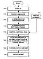
- FIG. 4Ais a flow diagram of one embodiment according to the disclosure.
- FIG. 4Bis a flow diagram of a second embodiment according to the disclosure.
- FIG. 5is a graphical display of functional yield curves relative to anteversion and inclination axes
- FIG. 6is a diagrammatic view of a display screen that guides navigation of a reamer
- FIG. 7is a diagrammatic view of an operating table
- FIGS. 8A-8Cillustrate a position of an anatomical plane relative to a plumb line plane.
- FIG. 1illustrates a surgical navigation system 100 , which includes a personal computer 102 having a CPU (not shown), internal memory (not shown), storage capacity (not shown), a monitor 104 , and a camera array 106 .
- the elements of the surgical navigation system 100are well known to those of skill in the art and there are many commercially available systems that can be adapted for use according to the methods of the present invention, such as the surgical navigation system as disclosed in published U.S. patent application 2001/0034530, the disclosure of which is incorporated by reference.
- a system and methods for performing a ball and socket joint arthroplasty with the aid of a surgical navigation systemis generally discussed in commonly assigned U.S. patent application Ser. No. 10/655,922 filed Sep. 5, 2003, also incorporated herein by reference.
- Functional driven positioning of one or more implant componentstakes into account range of motion and muscular tension to establish the orientation and position of the implants.
- orientation and positioning of an implant componentmay involve adhering to standardized position values that are not patient-specific and hence may result in less than optimal positioning and orientation from a functional standpoint.
- a surgeonmay adhere to a standard value of 20° of anteversion and 45° of inclination relative to the anatomical frontal plane for a cup implant as is well known in the art.
- Available medical literatureshows that the anatomical references used during a surgical procedure for these fixed average values of 20° and 45° may be somewhat arbitrary because these values are averages and may not correspond to the optimal function of the joint.
- the conventional approachwould dictate an amount of cup inclination and anteversion based on the frontal plane of the pelvis as measured while the patient is lying down without taking into account that when the patient stands the pelvis is flexed.
- the first goalis sufficient stability of the socket.
- an acetabular cup implantmust be well seated in the bone and positioned and oriented appropriately to withstand years of loading.
- the cup implantmust not be bored so deeply into the pelvic wall to compromise the structural integrity of same.
- the glenoid 154shoulder socket shown in FIG. 2 if machined or reamed to accommodate a shoulder implant component, must not be overly reamed in a manner that would compromise the structural integrity of the glenoid.
- the glenoid 154In a shoulder procedure, which typically does not employ a cup or socket implant, the glenoid 154 must be machined or reamed as necessary to create a surface suitable for accommodating a replacement ball implant attached to the humerus 148 wherein the ball implant interacts with the surface.
- the preparation of the glenoid 154affects the ultimate shoulder joint position, and thus, affects not only the range of motion of the shoulder joint but also has at least some affect on the arm length and/or medial-lateral arm position.
- the second goalis minimal tendency or risk of impingement/dislocation.
- These first two goals of (1) stability and (2) minimal risk of impingement/dislocationare typically the most important considerations for the socket because insufficient stability and a tendency for impingement and dislocation could severely impair the function of the joint.
- the additional goalsinclude a third goal of arriving at a socket position and orientation that results in matching the lateral-medial displacement of the operative limb to the non-operative limb (i.e., the contralateral side) or at least approaching lateral-medial displacement similar to the contralateral side.
- a fourth goalincludes positioning/orienting the socket such that the distal-proximal placement of the operative limb matches or approaches the contralateral side.
- a fifth goalis to match the length of the operative limb to the contralateral side.
- a sixth goalincludes matching (or approaching) the center of rotation of the contralateral side. It should be noted that matching the center of rotation to the contralateral side may be considered less important than matching the leg length or other of the goals.
- the surgeonmay establish an arbitrary center of rotation/first socket position that ignores precisely matching the socket position of the contralateral side but provides optimal stability for the socket. As discussed hereinbelow, the surgeon may then use left over degrees of freedom to fine-tune from the first socket position to achieve an optimal function and desired limb length
- a seventh goalis matching the kinematics of contralateral side (i.e., similar range of motion). However, depending on the anatomical constraints of the patient matching the kinematics may be less important than other of the goals. As should be evident from the “approaching” language above, the surgeon may have to compromise slightly or substantially on one or more of these additional goals in order to arrive at position and orientation of the socket that is optimal regarding the majority of the first through seventh goals. The degree to which one or more of the seven goals need be compromised may depend in large part on the anatomical constraints of the patient.
- the selection of implant(s)affects the aforementioned goals.
- the particular dimensions (i.e., size) and geometry (e.g., angles) of the selected implant(s)are an important consideration relative to achieving one or more of the first through seventh goals.
- a particular implantmay have a neck length longer or shorter than other available implants.
- the particular length of the neckaffects the lateral-medial and distal-proximal displacement of the operative femur relative to the contralateral side.
- the particular angle the neck makes with a femoral stem implantaffects the lateral-medial and distal-proximal displacements.
- a surgeonapplies suitable markers 120 a , 120 b , 120 c secured in fixed relation to appropriate anatomical landmarks, in a manner well known in the art, to input geometrical parameters of a ball and socket joint 122 and a limb 124 depending therefrom into the system 100 , and the surgeon may also digitize various positions of a movable probe 125 as is also well known in the art. In addition, one or more stationary markers 126 are typically digitized. The surgeon also digitizes range of motion data by moving the limb 122 about the joint 124 and measures soft tissue tension data with an appropriate force sensor as discussed hereinbelow.
- the system 100transforms these data to calculate a first socket position as well as a particular implant or combination of implant components that is determined optimal with regard to the first and second goals as well as all or any of the third through seventh goals. At this point the system 100 will indicate the best combination of implant components to achieve the desired functional result. As there is a finite number of implant component combinations, the system 100 will indicate that combination of implant components that best achieve the optimum result.
- the system 100preferably displays a graphical representation 130 , which includes a first axis 133 for anteversion and a second axis 136 for inclination.
- a dot 137represents the present socket position relative to inclination and anteversion.
- Function curves 138 a - 138 frepresent transformations of all available geometrical, range of motion, and soft tissue tension data relative to varying values of inclination and anteversion and such transformations are computed by the system with an appropriate algorithm.
- the system 100also determines a first implant component(s) with regard to the first and second goals and perhaps one or more of the third through seventh goals.
- the system 100utilizes an implant database 143 ( FIG. 4A ) having the geometrical properties of each potential implant for computing the optimal first implant.
- the system 100 and methodology disclosed hereintakes into account all of the above parameters at the same time.
- the algorithm used by the system 100uses the database 143 with all of the implants components and optimizes the above parameters by choosing an appropriate combination of components and respective alignments (e.g., head offset, neck angle, cup orientation) therefor.
- the implant components in the database 143can be complete sets of implants of varying sizes as well as modular implants that can be combined by the surgeon to produce a more customizable implant.
- the modular implantsinclude separate and interchangeable stems, necks and balls or heads.
- the system 100then indicates on the display 104 , the particular optimized implant(s) and also displays the graph 130 of the various function curves 138 a - 138 f for the particular optimized implant.
- some parametersare binary, e.g., no dislocation, while other parameters may have a small tolerance range such as a leg length tolerance range of +/ ⁇ 5 mm relative to the contralateral side. Any two points on any of the curves 138 a - 138 f are equivalent from a functional standpoint of the joint 124 .
- points 140 and 141produce an equivalent functional outcome in terms of range of motion and tension despite having different values of inclination and anteversion.
- the system 100can also display alternate graphs showing the results for other choices of implant components, such as the neighboring sizes to the determined optimum solution or a different implant family using an alternative implant design.
- a surgeonmay determine a minimum anteversion value 143 and a maximum anteversion value 146 with regard to the first and second goals of stability and non-impingement/dislocation.
- the surgeonmay also establish minimum and maximum values 148 and 150 between which the surgeon may manipulate from the position 137 to improve joint function without compromising the first and second goals.
- functionimproves from the curve 138 a toward the curve 138 f . Therefore, the surgeon may adjust inclination and anteversion from the position 137 to a position 152 of the curve 138 c rather than a position 154 of the curve 138 b , because the curve 138 c yields a better functional outcome than the curve 138 b.
- the soft tissue tension dataare collected by the system by any suitable pressure sensor built into the acetabular cup, or into the femoral head or neck implant of the trial implants.
- the pressure sensorsare conventional strain gauges that are built into the trial components. These trial components enable the surgeon to test the configuration to confirm that the optimum solution is in fact optimal for the patient.
- the pressure valuescan be transmitted to the system 100 wirelessly and can be related to the respective limb position.
- the surgeonmay use trial implant components that have not only the above pressure sensors but motorized parts that adjust one or more implant features such as neck offset/length or neck angle, and the system 100 could calculate soft tissue tension parameters relative to various values of neck length or neck offset angle.
- the systemis provided with lift-off data upon the system detecting displacement of the center of rotation of the joint 124 as is well known in the art.
- the performance of trials with a pressure sensormay be conducted after the system 100 determines the first socket position/first implant(s).
- the surgeoncould manipulate the neck angle and/or neck length and display a further function graph similar or identical to the graph 130 of FIG. 5 .
- the change in neck length/neck angleprovides further force data for further transformations for further function curves similar to the curves 138 a - 138 f allowing the surgeon to fine-tune from the first position to improve function relative to the third through seventh goals.
- a typical scenariowould be as follows.
- the surgeoncaptures preoperative range of motion.
- the surgeonprepares the acetabulum or glenoid and places a swivel trial.
- the surgeonreams a trial broach into the femur.
- the surgeonreams to a final position in terms of depth and anteversion, thus decreasing the degrees of freedom for later optimization.
- the surgeonnext places a trial neck and head and performs a further range of motion.
- the system 100then derives an optimal neck angle, head offset, anteversion, and inclination of cup.
- the surgeonplaces a preliminary broach in place rather than reaming to the final position in terms of depth and anteversion.
- maximum degrees of freedomare provided because the position is not final.
- the surgeonnext tests the trial neck and head and performs a range of motion analysis therefor.
- the system 100derives an optimal stem anteversion and all of the above.
- the surgeonnext verifies the proposed femoral components. Verification includes the assembly of the selected components in situ or if a automatically adjustable device is in place then the degrees of freedom of the device are adjusted accordingly.
- the trial neck with proposed angle and head with proposed offsetare mounted manually.
- the surgeonperforms one or more smart trials, utilizing motorized implant components as discussed above to adjust the proposed neck angle, offset, and anteversion in situ. Additional force data is collected, allowing further transformations and further graphical displays such as the graphical display 130 by the system 100 , and thus allowing the surgeon to fine-tune the implant component(s) geometry.
- the trial implantcould include an extensible femoral neck and a force sensor that communicates force data to the system so that during registration of the second movement the surgeon can assess the affect of soft tissue tension on the neck length. The surgeon may vary the neck length in the performance of movement analyses and transmit force data for various neck lengths.
- the surgeoncan use the system to determine an optimal neck length that provides suitable tension while also resulting in an offset that is cosmetically acceptable (i.e., within appropriate geometrical parameters). Finally, the surgeon navigates final components to the optimized positions. Depending on surgeon preferences, the above options or procedures can differ in order and degrees of freedom available for optimization.
- initial kinematics of the patientare taken into account. They can be used as a reference to document the improvement of the surgical measure.
- a first kinematic analysisis performed by moving the contralateral limb about the joint to obtain first kinematic data and the operative limb 124 is moved about the joint 122 to obtain second kinematic data that is compared to the first kinematic data.
- a block 160initializes the system 100 and allows input of patient biographical information and tests whether the markers 120 a - 120 c and the probe 125 are within the viewing volume of the camera array 106 .
- a block 164receives input from each of the markers for determining geometrical parameters, and a block 168 calculates range of motion by digitizing the markers 120 a - 120 c following or during movement of the limb 122 about the joint 124 within the viewing volume. While the limb is moved through a full range of motion the limb location is repeatedly digitized at various locations in a known manner. The surgeon typically assesses extreme positions such as maximum flexion, maximum extension, maximum internal rotation, maximum external rotation, maximum abduction, and maximum adduction.
- the surgeontypically also digitizes moderate positions of each of these.
- the surgeonneed not digitize a frontal plane such as the anatomical frontal pelvic plane 250 based upon the suspensory ligament 271 , a left and right ASIS 273 and pubic tubercles 275 (seen in FIG. 3 ) because the first kinematic data, comprising geometrical parameters and range of motion data, is sufficient to assess the kinematics of the joint and solve for an optimal socket position and in fact produces a better result.
- the functional frontal planes that are used in the system and method of the present inventionreplicates the pelvic position in certain poses, e.g. standing or sitting, relative to gravity. These functional frontal planes are then a patient specific reference to implant positioning in a static scenario.
- a block 172determines the soft tissue tension parameter of the joint 124 via wireless receipt of force data as described above.
- a block 176computes a functional goal by accessing the implant database 143 and performing an optimization algorithm that chooses the best implant(s) based on the geometrical parameters, the soft tissue tension data, the first and second goals, and one or more of the third through seventh goals.
- a block 180displays the optimal socket position and the optimal implant(s).
- the surgeonprepares the joint 124 for receipt of an implant, whether a trial implant or a final implant.
- Reaming/preparation of the joint 124could be guided by the system 100 as known in the art such as by guiding a suitable reamer (not shown but well known) having suitable active or passive tracking markers thereon.
- the implant(s)is installed into the joint 124 .
- the block 172could be repeated perhaps with the performance of a smart trial as discussed above to fine-tune the socket positioning and implant selection.
- the blocks 168 , 172could be either combined or separate as shown.
- a block 181 similar or identical to the block 180solves for a first socket position and a first implant by optimizing data obtained from the blocks 160 , 164 , 168 , 172 , and 143 .
- a block 190displays the functional attributes of the first socket position/first implant relative to varying values of inclination and anteversion. For example, the block 190 could display the point 137 ( FIG. 5 ) relative to the various curves 138 a - 138 f .
- the optimal socket position and optimal implant, respectivelyare selected. A smart trial, discussed above, could optionally be performed in between the block 190 and the blocks 192 , 194 to obtain further optimization data.
- navigation of a reaming tool 200may be accomplished by providing suitable indicia on the display 104 (see also FIG. 1 ).
- suitable indiciaFor example, one or more guide lines 204 a - 204 d that reflect the desired reaming location displayed on the display 104 .
- the position of the reaming tool 200is displayed in real-time by any suitable indicia such as a crucible 207 , and the crucible 207 is displayed relative to the guide lines 186 .
- the indiciacould further include a guide line 208 that reflects the maximum reaming depth. It should be noted that the surgeon may perform one or more virtual trials (as discussed in commonly assigned U.S. application Ser. No.
- the system 100would display the expected kinematic outcome of such virtual trial(s) to assess the surgeon's estimated optimal socket position. The surgeon may even perform further virtual trials utilizing different hypothetical implants having different dimensions. Through a process of trial and error, the surgeon could solve for the optimal socket position, and once an optimal socket position has been determined the system displays suitable indicia such as the guide lines 204 a and 204 b ( FIG. 6 ) to guide preparation of the joint.
- the surgeonmay optionally establish and track a gravitational or plumb line plane P relative to an anatomical plane of the patient during the data collection described in connection with the blocks 160 , 164 , 168 , and 172 described above.
- the plumb line plane Pallows the system to assess the position of the pelvis relative to gravity.
- optimal socket positioningis generally assessed with the pelvis in a neutral stance wherein the functional frontal plane of the pelvis offset relative to the plumb line plane P when the patient is lying down.
- the angle of the offsetvaries not only between genders but also depending on lifestyle, age, races, etc. It typically ranges from ⁇ 10 to +10 degrees but can also lie outside this range.
- Tracking the plumb line plane Pallows the system to guide joint preparation or implant navigation relative to the plumb line plane P or preferably relative to an established functional frontal plane, without having data obscured by imprecision caused by an non-level table exerting a gravitational affect on the pelvis or having the data obscured by shifting of the patient's pelvis during a procedure.
- An easy method to establish the plumb line plane P intraoperativelyuses one or more suitable levels 230 to level an operating table 235 .
- the table 235includes one or more suitable tracking markers 240 to enable the system to track the position and orientation of the table 235 .
- the table 235is moved from a first height position A to a second height position B, and the table position is digitized at each of these positions A and B to establish the plumb line plane P.
- a previously established functional frontal planecan now be tracked relative to the plumb line plane.
- the position and orientation of this planemay then be assessed relative to the plumb line plane P as illustrated in FIGS. 8A-8C .
- the reference positionis a neutral stance. This provides information relative to the appropriate positioning of the shoulder joint to maximize post operative flexibility and stability.
- the surgical navigation system 100includes appropriate software and circuitry to execute the disclosed functions.
- the computer program of the systemmay include any suitable user interface screens for executing the various features discussed herein.
Landscapes
- Health & Medical Sciences (AREA)
- Life Sciences & Earth Sciences (AREA)
- Surgery (AREA)
- Engineering & Computer Science (AREA)
- General Health & Medical Sciences (AREA)
- Animal Behavior & Ethology (AREA)
- Veterinary Medicine (AREA)
- Biomedical Technology (AREA)
- Heart & Thoracic Surgery (AREA)
- Public Health (AREA)
- Nuclear Medicine, Radiotherapy & Molecular Imaging (AREA)
- Medical Informatics (AREA)
- Molecular Biology (AREA)
- Oral & Maxillofacial Surgery (AREA)
- Orthopedic Medicine & Surgery (AREA)
- Transplantation (AREA)
- Pathology (AREA)
- Robotics (AREA)
- Biophysics (AREA)
- Physical Education & Sports Medicine (AREA)
- Cardiology (AREA)
- Vascular Medicine (AREA)
- Prostheses (AREA)
- Surgical Instruments (AREA)
Abstract
Description
Claims (21)
Priority Applications (4)
| Application Number | Priority Date | Filing Date | Title |
|---|---|---|---|
| US10/961,455US8007448B2 (en) | 2004-10-08 | 2004-10-08 | System and method for performing arthroplasty of a joint and tracking a plumb line plane |
| DE112005002453.9TDE112005002453B4 (en) | 2004-10-08 | 2005-10-07 | A system and method for performing arthroplasty of a joint and for tracking a vertical plane |
| PCT/IB2005/004073WO2006067634A1 (en) | 2004-10-08 | 2005-10-07 | System and method for performing arthroplasty of a joint and tracking a plumb line plane |
| JP2007535275AJP5132313B2 (en) | 2004-10-08 | 2005-10-07 | Method for controlling a surgical navigation system |
Applications Claiming Priority (1)
| Application Number | Priority Date | Filing Date | Title |
|---|---|---|---|
| US10/961,455US8007448B2 (en) | 2004-10-08 | 2004-10-08 | System and method for performing arthroplasty of a joint and tracking a plumb line plane |
Publications (2)
| Publication Number | Publication Date |
|---|---|
| US20060095047A1 US20060095047A1 (en) | 2006-05-04 |
| US8007448B2true US8007448B2 (en) | 2011-08-30 |
Family
ID=36263046
Family Applications (1)
| Application Number | Title | Priority Date | Filing Date |
|---|---|---|---|
| US10/961,455Active2029-01-18US8007448B2 (en) | 2004-10-08 | 2004-10-08 | System and method for performing arthroplasty of a joint and tracking a plumb line plane |
Country Status (4)
| Country | Link |
|---|---|
| US (1) | US8007448B2 (en) |
| JP (1) | JP5132313B2 (en) |
| DE (1) | DE112005002453B4 (en) |
| WO (1) | WO2006067634A1 (en) |
Cited By (54)
| Publication number | Priority date | Publication date | Assignee | Title |
|---|---|---|---|---|
| US20070179626A1 (en)* | 2005-11-30 | 2007-08-02 | De La Barrera Jose L M | Functional joint arthroplasty method |
| US20080221570A1 (en)* | 2002-08-09 | 2008-09-11 | Vineet Kumar Sarin | Non-imaging tracking tools and method for hip replacement surgery |
| US20090125117A1 (en)* | 2007-11-14 | 2009-05-14 | Francois Paradis | Leg alignment and length measurement in hip replacement surgery |
| US20090316967A1 (en)* | 2008-06-20 | 2009-12-24 | Universite De Bretagne Occidentale | Help system for implanting a hip prosthesis on an individual |
| US20100250284A1 (en)* | 2009-03-26 | 2010-09-30 | Martin Roche | System and method for an orthopedic dynamic data repository and registry for request |
| US20100274256A1 (en)* | 2009-04-27 | 2010-10-28 | Smith & Nephew, Inc. | System and Method for Identifying a Landmark |
| US20110010187A1 (en)* | 2007-09-12 | 2011-01-13 | Nobel Biocare Services Ag | Method and system for planning a medical procedure and generating data related to said medical procedure |
| US8460302B2 (en) | 2006-12-18 | 2013-06-11 | Otismed Corporation | Arthroplasty devices and related methods |
| US8460303B2 (en) | 2007-10-25 | 2013-06-11 | Otismed Corporation | Arthroplasty systems and devices, and related methods |
| US8480679B2 (en) | 2008-04-29 | 2013-07-09 | Otismed Corporation | Generation of a computerized bone model representative of a pre-degenerated state and useable in the design and manufacture of arthroplasty devices |
| US8483469B2 (en) | 2008-04-30 | 2013-07-09 | Otismed Corporation | System and method for image segmentation in generating computer models of a joint to undergo arthroplasty |
| US8532361B2 (en) | 2008-04-30 | 2013-09-10 | Otismed Corporation | System and method for image segmentation in generating computer models of a joint to undergo arthroplasty |
| USD691719S1 (en) | 2007-10-25 | 2013-10-15 | Otismed Corporation | Arthroplasty jig blank |
| US8588892B2 (en) | 2008-12-02 | 2013-11-19 | Avenir Medical Inc. | Method and system for aligning a prosthesis during surgery using active sensors |
| US8617175B2 (en) | 2008-12-16 | 2013-12-31 | Otismed Corporation | Unicompartmental customized arthroplasty cutting jigs and methods of making the same |
| US8617171B2 (en) | 2007-12-18 | 2013-12-31 | Otismed Corporation | Preoperatively planning an arthroplasty procedure and generating a corresponding patient specific arthroplasty resection guide |
| US8623023B2 (en) | 2009-04-27 | 2014-01-07 | Smith & Nephew, Inc. | Targeting an orthopaedic implant landmark |
| US8715291B2 (en) | 2007-12-18 | 2014-05-06 | Otismed Corporation | Arthroplasty system and related methods |
| US8734455B2 (en) | 2008-02-29 | 2014-05-27 | Otismed Corporation | Hip resurfacing surgical guide tool |
| US8737700B2 (en) | 2007-12-18 | 2014-05-27 | Otismed Corporation | Preoperatively planning an arthroplasty procedure and generating a corresponding patient specific arthroplasty resection guide |
| US8777875B2 (en) | 2008-07-23 | 2014-07-15 | Otismed Corporation | System and method for manufacturing arthroplasty jigs having improved mating accuracy |
| US8784425B2 (en) | 2007-02-28 | 2014-07-22 | Smith & Nephew, Inc. | Systems and methods for identifying landmarks on orthopedic implants |
| US8814868B2 (en) | 2007-02-28 | 2014-08-26 | Smith & Nephew, Inc. | Instrumented orthopaedic implant for identifying a landmark |
| US8890511B2 (en) | 2011-01-25 | 2014-11-18 | Smith & Nephew, Inc. | Targeting operation sites |
| US8968320B2 (en) | 2007-12-18 | 2015-03-03 | Otismed Corporation | System and method for manufacturing arthroplasty jigs |
| US9017336B2 (en) | 2006-02-15 | 2015-04-28 | Otismed Corporation | Arthroplasty devices and related methods |
| US9138319B2 (en) | 2010-12-17 | 2015-09-22 | Intellijoint Surgical Inc. | Method and system for aligning a prosthesis during surgery |
| US9168153B2 (en) | 2011-06-16 | 2015-10-27 | Smith & Nephew, Inc. | Surgical alignment using references |
| US9220514B2 (en) | 2008-02-28 | 2015-12-29 | Smith & Nephew, Inc. | System and method for identifying a landmark |
| US9247998B2 (en) | 2013-03-15 | 2016-02-02 | Intellijoint Surgical Inc. | System and method for intra-operative leg position measurement |
| US9308102B2 (en) | 2013-03-04 | 2016-04-12 | Howmedica Osteonics Corp. | Acetabular cup positioning device |
| US9314188B2 (en) | 2012-04-12 | 2016-04-19 | Intellijoint Surgical Inc. | Computer-assisted joint replacement surgery and navigation systems |
| US9402637B2 (en) | 2012-10-11 | 2016-08-02 | Howmedica Osteonics Corporation | Customized arthroplasty cutting guides and surgical methods using the same |
| US9526441B2 (en) | 2011-05-06 | 2016-12-27 | Smith & Nephew, Inc. | Targeting landmarks of orthopaedic devices |
| US9539037B2 (en) | 2010-06-03 | 2017-01-10 | Smith & Nephew, Inc. | Orthopaedic implants |
| US9649170B2 (en) | 2007-12-18 | 2017-05-16 | Howmedica Osteonics Corporation | Arthroplasty system and related methods |
| US9808262B2 (en) | 2006-02-15 | 2017-11-07 | Howmedica Osteonics Corporation | Arthroplasty devices and related methods |
| US10136952B2 (en) | 2016-06-16 | 2018-11-27 | Zimmer, Inc. | Soft tissue balancing in articular surgery |
| US20190133693A1 (en)* | 2017-06-19 | 2019-05-09 | Techmah Medical Llc | Surgical navigation of the hip using fluoroscopy and tracking sensors |
| US10350087B2 (en) | 2013-03-18 | 2019-07-16 | Medacta International Sa | Set of instruments for the implantation of an acetabular prosthesis |
| US10405993B2 (en) | 2013-11-13 | 2019-09-10 | Tornier Sas | Shoulder patient specific instrument |
| US10582934B2 (en) | 2007-11-27 | 2020-03-10 | Howmedica Osteonics Corporation | Generating MRI images usable for the creation of 3D bone models employed to make customized arthroplasty jigs |
| US10716676B2 (en) | 2008-06-20 | 2020-07-21 | Tornier Sas | Method for modeling a glenoid surface of a scapula, apparatus for implanting a glenoid component of a shoulder prosthesis, and method for producing such a component |
| US10959742B2 (en) | 2017-07-11 | 2021-03-30 | Tornier, Inc. | Patient specific humeral cutting guides |
| US11065016B2 (en) | 2015-12-16 | 2021-07-20 | Howmedica Osteonics Corp. | Patient specific instruments and methods for joint prosthesis |
| US11166733B2 (en) | 2017-07-11 | 2021-11-09 | Howmedica Osteonics Corp. | Guides and instruments for improving accuracy of glenoid implant placement |
| US11229489B2 (en) | 2016-06-16 | 2022-01-25 | Zimmer, Inc. | Soft tissue balancing in articular surgery |
| EP3992978A1 (en)* | 2020-10-27 | 2022-05-04 | Zimmer, Inc. | Knee arthroplasty functional digital twin |
| US11357644B2 (en) | 2011-10-24 | 2022-06-14 | Synvasive Technology, Inc. | Knee balancing devices, systems and methods |
| US11999065B2 (en) | 2020-10-30 | 2024-06-04 | Mako Surgical Corp. | Robotic surgical system with motorized movement to a starting pose for a registration or calibration routine |
| USD1044829S1 (en) | 2021-07-29 | 2024-10-01 | Mako Surgical Corp. | Display screen or portion thereof with graphical user interface |
| US12193939B2 (en) | 2017-12-29 | 2025-01-14 | Howmedica Osteonics Corp. | Patient specific humeral implant components |
| US12193718B2 (en) | 2021-04-09 | 2025-01-14 | Smith & Nephew, Inc. | Orthopedic surgical instrument |
| US12324615B2 (en) | 2021-11-05 | 2025-06-10 | Mako Surgical Corp. | Assessment of soft tissue tension in hip procedures |
Families Citing this family (52)
| Publication number | Priority date | Publication date | Assignee | Title |
|---|---|---|---|---|
| FR2816200A1 (en) | 2000-11-06 | 2002-05-10 | Praxim | DETERMINING THE POSITION OF A KNEE PROSTHESIS |
| EA008902B1 (en)* | 2003-11-12 | 2007-08-31 | Интернэшнл Пэйтент Оунерз (Кайман) Лимитед | A gauge for use in a surgical procedure |
| US7458989B2 (en)* | 2005-06-30 | 2008-12-02 | University Of Florida Rearch Foundation, Inc. | Intraoperative joint force measuring device, system and method |
| US8337426B2 (en)* | 2009-03-24 | 2012-12-25 | Biomet Manufacturing Corp. | Method and apparatus for aligning and securing an implant relative to a patient |
| US9289253B2 (en) | 2006-02-27 | 2016-03-22 | Biomet Manufacturing, Llc | Patient-specific shoulder guide |
| US9907659B2 (en) | 2007-04-17 | 2018-03-06 | Biomet Manufacturing, Llc | Method and apparatus for manufacturing an implant |
| US8167823B2 (en)* | 2009-03-24 | 2012-05-01 | Biomet Manufacturing Corp. | Method and apparatus for aligning and securing an implant relative to a patient |
| US9339278B2 (en) | 2006-02-27 | 2016-05-17 | Biomet Manufacturing, Llc | Patient-specific acetabular guides and associated instruments |
| US9173661B2 (en) | 2006-02-27 | 2015-11-03 | Biomet Manufacturing, Llc | Patient specific alignment guide with cutting surface and laser indicator |
| US8603180B2 (en) | 2006-02-27 | 2013-12-10 | Biomet Manufacturing, Llc | Patient-specific acetabular alignment guides |
| US9345548B2 (en) | 2006-02-27 | 2016-05-24 | Biomet Manufacturing, Llc | Patient-specific pre-operative planning |
| US8591516B2 (en) | 2006-02-27 | 2013-11-26 | Biomet Manufacturing, Llc | Patient-specific orthopedic instruments |
| US8407067B2 (en) | 2007-04-17 | 2013-03-26 | Biomet Manufacturing Corp. | Method and apparatus for manufacturing an implant |
| US9918740B2 (en) | 2006-02-27 | 2018-03-20 | Biomet Manufacturing, Llc | Backup surgical instrument system and method |
| US20150335438A1 (en) | 2006-02-27 | 2015-11-26 | Biomet Manufacturing, Llc. | Patient-specific augments |
| US7699793B2 (en)* | 2006-03-07 | 2010-04-20 | Brainlab Ag | Method and device for detecting and localising an impingement of joint components |
| JP2009529954A (en)* | 2006-03-14 | 2009-08-27 | マコ サージカル コーポレーション | Prosthetic device and system and method for implanting a prosthetic device |
| US9795399B2 (en) | 2006-06-09 | 2017-10-24 | Biomet Manufacturing, Llc | Patient-specific knee alignment guide and associated method |
| EP2032087A1 (en)* | 2006-06-19 | 2009-03-11 | IGO Technologies Inc. | Joint placement methods and apparatuses |
| EP1882457B1 (en)* | 2006-07-25 | 2012-03-28 | BrainLAB AG | Method and device for representing the orientation of an object to ball joints |
| US8214016B2 (en) | 2006-12-12 | 2012-07-03 | Perception Raisonnement Action En Medecine | System and method for determining an optimal type and position of an implant |
| US20100153081A1 (en) | 2008-12-11 | 2010-06-17 | Mako Surgical Corp. | Implant planning for multiple implant components using constraints |
| EP2136715B1 (en)* | 2007-04-19 | 2014-06-25 | Mako Surgical Corp. | Implant planning using captured joint motion information |
| US9044345B2 (en)* | 2007-05-22 | 2015-06-02 | Brainlab Ag | Navigated placement of pelvic implant based on combined anteversion by applying Ranawat's sign or via arithmetic formula |
| DE102007049668B3 (en)* | 2007-10-17 | 2009-04-16 | Aesculap Ag | Method and device for determining the angular position of an acetabular cup in a pelvic bone |
| DE102007049671A1 (en)* | 2007-10-17 | 2009-04-30 | Aesculap Ag | Method and device for determining the frontal plane of the pelvic bone |
| US8078440B2 (en) | 2008-09-19 | 2011-12-13 | Smith & Nephew, Inc. | Operatively tuning implants for increased performance |
| DE102010010192A1 (en)* | 2010-03-04 | 2011-09-08 | Siemens Aktiengesellschaft | Medical examination and / or treatment device |
| US9358130B2 (en)* | 2012-03-29 | 2016-06-07 | DePuy Synthes Products, Inc. | Surgical instrument and method of positioning an acetabular prosthetic component |
| JP2014504161A (en) | 2010-09-01 | 2014-02-20 | メイヨ フォンデーシヨン フォー メディカル エジュケーション アンド リサーチ | Method for optimizing arthroplasty component design |
| US9320608B2 (en) | 2010-09-01 | 2016-04-26 | Mayo Foundation For Medical Education And Research | Method for optimization of joint arthroplasty component design |
| US9968376B2 (en) | 2010-11-29 | 2018-05-15 | Biomet Manufacturing, Llc | Patient-specific orthopedic instruments |
| EP2672916A4 (en)* | 2011-02-08 | 2015-01-14 | Gen Hospital Corp | SYSTEMS AND METHODS FOR PATIENT POSITIONING |
| EP2819610B1 (en) | 2012-02-29 | 2023-04-12 | Smith & Nephew, Inc. | Determining anatomical orientations |
| CN102688097B (en)* | 2012-05-14 | 2014-11-26 | 清华大学 | Attitude acquisition method and system for acetabulum and femoral head in artificial hip joint replacement |
| US20140031829A1 (en)* | 2012-07-30 | 2014-01-30 | Orthosoft, Inc. | Method and system for creating frame of reference for cas with inertial sensors |
| SE536759C2 (en) | 2012-10-18 | 2014-07-15 | Ortoma Ab | Method and system for planning position for implant component |
| US9585768B2 (en) | 2013-03-15 | 2017-03-07 | DePuy Synthes Products, Inc. | Acetabular cup prosthesis alignment system and method |
| EP3057524B1 (en) | 2013-10-10 | 2019-11-20 | Imascap | Method for designing and producing a shoulder surgery guide |
| EP3925574A1 (en)* | 2013-11-08 | 2021-12-22 | Imascap | Pre-operatively planned adaptive glenoid implants and method for planning its design |
| US20150201974A1 (en)* | 2014-01-21 | 2015-07-23 | Warsaw Orthopedic, Inc. | Surgical instrument and method of use |
| US10758198B2 (en)* | 2014-02-25 | 2020-09-01 | DePuy Synthes Products, Inc. | Systems and methods for intra-operative image analysis |
| US12295772B2 (en) | 2014-02-25 | 2025-05-13 | DePuy Synthes Products, Inc. | Systems and methods for intra-operative image analysis |
| US10433914B2 (en) | 2014-02-25 | 2019-10-08 | JointPoint, Inc. | Systems and methods for intra-operative image analysis |
| CN106535827B (en)* | 2014-06-10 | 2018-04-06 | 梅约医学教育与研究基金会 | Method for optimizing arthroplasty component design |
| AU2015394606C1 (en) | 2015-05-08 | 2018-08-16 | Smith & Nephew Asia Pacific Pte. Limited | Determination of an implant orientation relative to a bone |
| US9913691B2 (en) | 2015-08-12 | 2018-03-13 | The Cleveland Clinic Foundation | System and method for model-based surgical planning |
| CA3039654A1 (en)* | 2016-10-07 | 2018-04-12 | New York Society For The Relief Of The Ruptured And Crippled, Maintaining The Hospital For Special Surgery | Patient specific 3-d interactive total joint model and surgical planning system |
| US10722310B2 (en) | 2017-03-13 | 2020-07-28 | Zimmer Biomet CMF and Thoracic, LLC | Virtual surgery planning system and method |
| CA3178420A1 (en) | 2020-05-15 | 2021-11-18 | John Black | Dynamic registration of anatomy using augmented reality |
| US11107586B1 (en) | 2020-06-24 | 2021-08-31 | Cuptimize, Inc. | System and method for analyzing acetabular cup position |
| US11887306B2 (en) | 2021-08-11 | 2024-01-30 | DePuy Synthes Products, Inc. | System and method for intraoperatively determining image alignment |
Citations (86)
| Publication number | Priority date | Publication date | Assignee | Title |
|---|---|---|---|---|
| US4323459A (en) | 1978-08-09 | 1982-04-06 | Petrolite Corporation | Process of inhibiting scale formation in aqueous systems using quaternary ammonium salts of α-1,4-thiazine alkanephosphonic acids |
| US4396945A (en) | 1981-08-19 | 1983-08-02 | Solid Photography Inc. | Method of sensing the position and orientation of elements in space |
| US4722056A (en) | 1986-02-18 | 1988-01-26 | Trustees Of Dartmouth College | Reference display systems for superimposing a tomagraphic image onto the focal plane of an operating microscope |
| EP0326768A2 (en) | 1988-02-01 | 1989-08-09 | Faro Medical Technologies Inc. | Computer-aided surgery apparatus |
| US4869247A (en) | 1988-03-11 | 1989-09-26 | The University Of Virginia Alumni Patents Foundation | Video tumor fighting system |
| DE3904595C1 (en) | 1989-02-16 | 1990-04-19 | Deutsches Krebsforschungszentrum Stiftung Des Oeffentlichen Rechts, 6900 Heidelberg, De | Device for determining the spatial coordinates of stereotactic target points by means of X-ray pictures |
| US4923459A (en) | 1987-09-14 | 1990-05-08 | Kabushiki Kaisha Toshiba | Stereotactics apparatus |
| US4945914A (en) | 1987-11-10 | 1990-08-07 | Allen George S | Method and apparatus for providing related images over time of a portion of the anatomy using at least four fiducial implants |
| US4951653A (en) | 1988-03-02 | 1990-08-28 | Laboratory Equipment, Corp. | Ultrasound brain lesioning system |
| US5142930A (en) | 1987-11-10 | 1992-09-01 | Allen George S | Interactive image-guided surgical system |
| US5186174A (en) | 1987-05-21 | 1993-02-16 | G. M. Piaff | Process and device for the reproducible optical representation of a surgical operation |
| US5197488A (en) | 1991-04-05 | 1993-03-30 | N. K. Biotechnical Engineering Co. | Knee joint load measuring instrument and joint prosthesis |
| US5198877A (en) | 1990-10-15 | 1993-03-30 | Pixsys, Inc. | Method and apparatus for three-dimensional non-contact shape sensing |
| US5222499A (en) | 1989-11-15 | 1993-06-29 | Allen George S | Method and apparatus for imaging the anatomy |
| US5309101A (en) | 1993-01-08 | 1994-05-03 | General Electric Company | Magnetic resonance imaging in an inhomogeneous magnetic field |
| US5383454A (en) | 1990-10-19 | 1995-01-24 | St. Louis University | System for indicating the position of a surgical probe within a head on an image of the head |
| US5394875A (en) | 1993-10-21 | 1995-03-07 | Lewis; Judith T. | Automatic ultrasonic localization of targets implanted in a portion of the anatomy |
| US5494034A (en) | 1987-05-27 | 1996-02-27 | Georg Schlondorff | Process and device for the reproducible optical representation of a surgical operation |
| US5515160A (en) | 1992-03-12 | 1996-05-07 | Aesculap Ag | Method and apparatus for representing a work area in a three-dimensional structure |
| US5551429A (en) | 1993-02-12 | 1996-09-03 | Fitzpatrick; J. Michael | Method for relating the data of an image space to physical space |
| US5575794A (en) | 1993-02-12 | 1996-11-19 | Walus; Richard L. | Tool for implanting a fiducial marker |
| US5590215A (en) | 1993-10-15 | 1996-12-31 | Allen; George S. | Method for providing medical images |
| US5617857A (en) | 1995-06-06 | 1997-04-08 | Image Guided Technologies, Inc. | Imaging system having interactive medical instruments and methods |
| US5622170A (en) | 1990-10-19 | 1997-04-22 | Image Guided Technologies, Inc. | Apparatus for determining the position and orientation of an invasive portion of a probe inside a three-dimensional body |
| US5638819A (en) | 1995-08-29 | 1997-06-17 | Manwaring; Kim H. | Method and apparatus for guiding an instrument to a target |
| US5665090A (en) | 1992-09-09 | 1997-09-09 | Dupuy Inc. | Bone cutting apparatus and method |
| US5682886A (en)* | 1995-12-26 | 1997-11-04 | Musculographics Inc | Computer-assisted surgical system |
| US5690635A (en) | 1988-04-26 | 1997-11-25 | The Board Of Regents Of The University Of Washington | Prosthesis template for use in a robot-aided system for surgery |
| US5695501A (en) | 1994-09-30 | 1997-12-09 | Ohio Medical Instrument Company, Inc. | Apparatus for neurosurgical stereotactic procedures |
| US5704897A (en) | 1992-07-31 | 1998-01-06 | Truppe; Michael J. | Apparatus and method for registration of points of a data field with respective points of an optical image |
| US5711299A (en) | 1996-01-26 | 1998-01-27 | Manwaring; Kim H. | Surgical guidance method and system for approaching a target within a body |
| US5752513A (en) | 1995-06-07 | 1998-05-19 | Biosense, Inc. | Method and apparatus for determining position of object |
| US5769789A (en) | 1993-02-12 | 1998-06-23 | George S. Allen | Automatic technique for localizing externally attached fiducial markers in volume images of the head |
| US5797924A (en) | 1993-11-02 | 1998-08-25 | Loma Linda University Medical Center | Stereotactic fixation system and calibration phantom |
| US5871445A (en) | 1993-04-26 | 1999-02-16 | St. Louis University | System for indicating the position of a surgical probe within a head on an image of the head |
| US5880976A (en) | 1997-02-21 | 1999-03-09 | Carnegie Mellon University | Apparatus and method for facilitating the implantation of artificial components in joints |
| US5891157A (en) | 1994-09-30 | 1999-04-06 | Ohio Medical Instrument Company, Inc. | Apparatus for surgical stereotactic procedures |
| EP0705075B1 (en) | 1993-06-21 | 1999-04-21 | Osteonics Corp. | Apparatus for aligning knee prostheses |
| US5907395A (en) | 1997-06-06 | 1999-05-25 | Image Guided Technologies, Inc. | Optical fiber probe for position measurement |
| US5921992A (en) | 1997-04-11 | 1999-07-13 | Radionics, Inc. | Method and system for frameless tool calibration |
| US5954648A (en) | 1996-04-29 | 1999-09-21 | U.S. Philips Corporation | Image guided surgery system |
| US5970499A (en) | 1997-04-11 | 1999-10-19 | Smith; Kurt R. | Method and apparatus for producing and accessing composite data |
| EP0705074B1 (en) | 1993-06-21 | 2000-05-10 | Osteonics Corp. | Apparatus for locating functional structures of the leg during knee surgery |
| US6081336A (en) | 1997-09-26 | 2000-06-27 | Picker International, Inc. | Microscope calibrator |
| US6112113A (en) | 1997-07-03 | 2000-08-29 | U.S. Philips Corporation | Image-guided surgery system |
| US6205411B1 (en) | 1997-02-21 | 2001-03-20 | Carnegie Mellon University | Computer-assisted surgery planner and intra-operative guidance system |
| US20010034530A1 (en) | 2000-01-27 | 2001-10-25 | Malackowski Donald W. | Surgery system |
| JP3267054B2 (en) | 1994-06-13 | 2002-03-18 | トヨタ自動車株式会社 | Power storage device for solar power |
| US6385475B1 (en) | 1997-03-11 | 2002-05-07 | Philippe Cinquin | Process and device for the preoperative determination of the positioning data of endoprosthetic parts |
| US6430434B1 (en) | 1998-12-14 | 2002-08-06 | Integrated Surgical Systems, Inc. | Method for determining the location and orientation of a bone for computer-assisted orthopedic procedures using intraoperatively attached markers |
| US6453190B1 (en) | 1996-02-15 | 2002-09-17 | Biosense, Inc. | Medical probes with field transducers |
| US20020133160A1 (en) | 2001-02-28 | 2002-09-19 | Axelson Stuart L. | Systems used in performing femoral and tibial resection in knee surgery |
| WO2003041566A2 (en) | 2001-11-14 | 2003-05-22 | University Of British Columbia | Methods and systems for intraoperative measurement of soft tissue constraints in computer aided total joint replacement surgery |
| US6569169B2 (en) | 2000-10-11 | 2003-05-27 | Stryker Leibinger Gmbh & Co Kg | Device for detecting or following the position of a bone |
| US6595997B2 (en) | 2001-02-28 | 2003-07-22 | Howmedica Osteonics Corp. | Methods used in performing femoral and tibial resection in knee surgery |
| WO2003065949A2 (en) | 2002-02-08 | 2003-08-14 | Whiteside Leo A | Apparatus for fitting implants and balancing ligaments |
| US20030153829A1 (en) | 2002-02-13 | 2003-08-14 | Kinamed, Inc. | Non-imaging, computer assisted navigation system for hip replacement surgery |
| US6676706B1 (en) | 2000-04-26 | 2004-01-13 | Zimmer Technology, Inc. | Method and apparatus for performing a minimally invasive total hip arthroplasty |
| US20040034313A1 (en) | 2000-12-15 | 2004-02-19 | Aesculap Ag & Co. Kg | Method and device for determining the mechanical axis of a femur |
| US6695850B2 (en) | 2002-02-20 | 2004-02-24 | Robert L. Diaz | Minimally invasive total hip replacement |
| US6702821B2 (en) | 2000-01-14 | 2004-03-09 | The Bonutti 2003 Trust A | Instrumentation for minimally invasive joint replacement and methods for using same |
| US20040102866A1 (en) | 2001-01-29 | 2004-05-27 | Harris Simon James | Modelling for surgery |
| US20040106916A1 (en) | 2002-03-06 | 2004-06-03 | Z-Kat, Inc. | Guidance system and method for surgical procedures with improved feedback |
| US20040106869A1 (en) | 2002-11-29 | 2004-06-03 | Ron-Tech Medical Ltd. | Ultrasound tracking device, system and method for intrabody guiding procedures |
| US20040106861A1 (en) | 2002-12-03 | 2004-06-03 | Francois Leitner | Method of determining the position of the articular point of a joint |
| US20040105086A1 (en) | 2002-12-02 | 2004-06-03 | Francois Leitner | Localization device display method and apparatus |
| US20040117026A1 (en) | 2002-09-24 | 2004-06-17 | Gregor Tuma | Device and method for determining the aperture angle of a joint |
| US20040147927A1 (en) | 2002-11-07 | 2004-07-29 | Imaging Therapeutics, Inc. | Methods for determining meniscal size and shape and for devising treatment |
| US20040152972A1 (en) | 2003-01-30 | 2004-08-05 | Mark Hunter | Method and apparatus for post-operative tuning of a spinal implant |
| US20040171924A1 (en)* | 2003-01-30 | 2004-09-02 | Mire David A. | Method and apparatus for preplanning a surgical procedure |
| US6827723B2 (en) | 2001-02-27 | 2004-12-07 | Smith & Nephew, Inc. | Surgical navigation systems and processes for unicompartmental knee arthroplasty |
| US6859661B2 (en) | 2001-01-25 | 2005-02-22 | Finsbury (Development) Limited | Surgical system for use in the course of a knee replacement operation |
| US20050065617A1 (en) | 2003-09-05 | 2005-03-24 | Moctezuma De La Barrera Jose Luis | System and method of performing ball and socket joint arthroscopy |
| US6877239B2 (en) | 2001-09-15 | 2005-04-12 | Aesculap Ag & Co. Kg | Method and device for checking a marking element for displacement |
| US20050101966A1 (en) | 2000-11-06 | 2005-05-12 | Stephane Lavallee | System for determining the position of a knee prosthesis |
| US20050113720A1 (en) | 1998-11-10 | 2005-05-26 | Philippe Cinquin | Method and device for determining the center of a joint |
| WO2005072629A1 (en) | 2004-01-16 | 2005-08-11 | Smith & Nephew, Inc. | Computer-assisted ligament balancing in total knee arthroplasty |
| US20050203384A1 (en) | 2002-06-21 | 2005-09-15 | Marwan Sati | Computer assisted system and method for minimal invasive hip, uni knee and total knee replacement |
| EP1399707B1 (en) | 2001-02-07 | 2006-06-21 | Aesculap AG & Co. KG | Method and device for determining the contour of a recess in a piece of material |
| US20060235538A1 (en) | 2005-04-13 | 2006-10-19 | Tornier | Surgical apparatus for implantation of a partial of total knee prosthesis |
| US20070179626A1 (en) | 2005-11-30 | 2007-08-02 | De La Barrera Jose L M | Functional joint arthroplasty method |
| US7275218B2 (en) | 2002-03-29 | 2007-09-25 | Depuy Products, Inc. | Method, apparatus, and program for analyzing a prosthetic device |
| EP1417941B1 (en) | 2002-11-05 | 2008-02-06 | BrainLAB AG | Method and device for registering a femoral implant |
| US7427200B2 (en) | 2002-04-16 | 2008-09-23 | Noble Philip C | Computer-based training methods for surgical procedures |
| US7657298B2 (en) | 2004-03-11 | 2010-02-02 | Stryker Leibinger Gmbh & Co. Kg | System, device, and method for determining a position of an object |
| US7662113B2 (en) | 2004-11-05 | 2010-02-16 | California Institute Of Technology | Fingertip tracker |
Family Cites Families (5)
| Publication number | Priority date | Publication date | Assignee | Title |
|---|---|---|---|---|
| US5309001A (en)* | 1991-11-25 | 1994-05-03 | Sharp Kabushiki Kaisha | Light-emitting diode having a surface electrode of a tree-like form |
| US5769092A (en)* | 1996-02-22 | 1998-06-23 | Integrated Surgical Systems, Inc. | Computer-aided system for revision total hip replacement surgery |
| US6283999B1 (en)* | 1999-01-29 | 2001-09-04 | Depuy Orthopaedics, Inc. | Shoulder prothesis with humeral fracture stem |
| US7001346B2 (en)* | 2001-11-14 | 2006-02-21 | Michael R. White | Apparatus and methods for making intraoperative orthopedic measurements |
| EP1487385A2 (en)* | 2002-03-19 | 2004-12-22 | The Board of Trustees for the University of Illinois | System and method for prosthetic fitting and balancing in joints |
- 2004
- 2004-10-08USUS10/961,455patent/US8007448B2/enactiveActive
- 2005
- 2005-10-07DEDE112005002453.9Tpatent/DE112005002453B4/ennot_activeExpired - Lifetime
- 2005-10-07WOPCT/IB2005/004073patent/WO2006067634A1/enactiveApplication Filing
- 2005-10-07JPJP2007535275Apatent/JP5132313B2/ennot_activeExpired - Lifetime
Patent Citations (110)
| Publication number | Priority date | Publication date | Assignee | Title |
|---|---|---|---|---|
| US4323459A (en) | 1978-08-09 | 1982-04-06 | Petrolite Corporation | Process of inhibiting scale formation in aqueous systems using quaternary ammonium salts of α-1,4-thiazine alkanephosphonic acids |
| US4396945A (en) | 1981-08-19 | 1983-08-02 | Solid Photography Inc. | Method of sensing the position and orientation of elements in space |
| US4722056A (en) | 1986-02-18 | 1988-01-26 | Trustees Of Dartmouth College | Reference display systems for superimposing a tomagraphic image onto the focal plane of an operating microscope |
| US5186174A (en) | 1987-05-21 | 1993-02-16 | G. M. Piaff | Process and device for the reproducible optical representation of a surgical operation |
| US5494034A (en) | 1987-05-27 | 1996-02-27 | Georg Schlondorff | Process and device for the reproducible optical representation of a surgical operation |
| US4923459A (en) | 1987-09-14 | 1990-05-08 | Kabushiki Kaisha Toshiba | Stereotactics apparatus |
| US5094241A (en) | 1987-11-10 | 1992-03-10 | Allen George S | Apparatus for imaging the anatomy |
| US4945914A (en) | 1987-11-10 | 1990-08-07 | Allen George S | Method and apparatus for providing related images over time of a portion of the anatomy using at least four fiducial implants |
| US5211164A (en) | 1987-11-10 | 1993-05-18 | Allen George S | Method of locating a target on a portion of anatomy |
| US4991579A (en) | 1987-11-10 | 1991-02-12 | Allen George S | Method and apparatus for providing related images over time of a portion of the anatomy using fiducial implants |
| US5016639A (en) | 1987-11-10 | 1991-05-21 | Allen George S | Method and apparatus for imaging the anatomy |
| US5397329A (en) | 1987-11-10 | 1995-03-14 | Allen; George S. | Fiducial implant and system of such implants |
| US5097839A (en) | 1987-11-10 | 1992-03-24 | Allen George S | Apparatus for imaging the anatomy |
| US5119817A (en) | 1987-11-10 | 1992-06-09 | Allen George S | Apparatus for imaging the anatomy |
| US5142930A (en) | 1987-11-10 | 1992-09-01 | Allen George S | Interactive image-guided surgical system |
| US5178164A (en) | 1987-11-10 | 1993-01-12 | Allen George S | Method for implanting a fiducial implant into a patient |
| US5230338A (en) | 1987-11-10 | 1993-07-27 | Allen George S | Interactive image-guided surgical system for displaying images corresponding to the placement of a surgical tool or the like |
| EP0326768A2 (en) | 1988-02-01 | 1989-08-09 | Faro Medical Technologies Inc. | Computer-aided surgery apparatus |
| US4951653A (en) | 1988-03-02 | 1990-08-28 | Laboratory Equipment, Corp. | Ultrasound brain lesioning system |
| US4869247A (en) | 1988-03-11 | 1989-09-26 | The University Of Virginia Alumni Patents Foundation | Video tumor fighting system |
| US5690635A (en) | 1988-04-26 | 1997-11-25 | The Board Of Regents Of The University Of Washington | Prosthesis template for use in a robot-aided system for surgery |
| DE3904595C1 (en) | 1989-02-16 | 1990-04-19 | Deutsches Krebsforschungszentrum Stiftung Des Oeffentlichen Rechts, 6900 Heidelberg, De | Device for determining the spatial coordinates of stereotactic target points by means of X-ray pictures |
| US5222499A (en) | 1989-11-15 | 1993-06-29 | Allen George S | Method and apparatus for imaging the anatomy |
| US5198877A (en) | 1990-10-15 | 1993-03-30 | Pixsys, Inc. | Method and apparatus for three-dimensional non-contact shape sensing |
| USRE35816E (en) | 1990-10-15 | 1998-06-02 | Image Guided Technologies Inc. | Method and apparatus for three-dimensional non-contact shape sensing |
| US5987349A (en) | 1990-10-19 | 1999-11-16 | Image Guided Technologies, Inc. | Method for determining the position and orientation of two moveable objects in three-dimensional space |
| US5851183A (en) | 1990-10-19 | 1998-12-22 | St. Louis University | System for indicating the position of a surgical probe within a head on an image of the head |
| US5383454A (en) | 1990-10-19 | 1995-01-24 | St. Louis University | System for indicating the position of a surgical probe within a head on an image of the head |
| US5383454B1 (en) | 1990-10-19 | 1996-12-31 | Univ St Louis | System for indicating the position of a surgical probe within a head on an image of the head |
| US5891034A (en) | 1990-10-19 | 1999-04-06 | St. Louis University | System for indicating the position of a surgical probe within a head on an image of the head |
| US5622170A (en) | 1990-10-19 | 1997-04-22 | Image Guided Technologies, Inc. | Apparatus for determining the position and orientation of an invasive portion of a probe inside a three-dimensional body |
| US5197488A (en) | 1991-04-05 | 1993-03-30 | N. K. Biotechnical Engineering Co. | Knee joint load measuring instrument and joint prosthesis |
| US5515160A (en) | 1992-03-12 | 1996-05-07 | Aesculap Ag | Method and apparatus for representing a work area in a three-dimensional structure |
| US5704897A (en) | 1992-07-31 | 1998-01-06 | Truppe; Michael J. | Apparatus and method for registration of points of a data field with respective points of an optical image |
| US5665090A (en) | 1992-09-09 | 1997-09-09 | Dupuy Inc. | Bone cutting apparatus and method |
| US5309101A (en) | 1993-01-08 | 1994-05-03 | General Electric Company | Magnetic resonance imaging in an inhomogeneous magnetic field |
| US5916164A (en) | 1993-02-12 | 1999-06-29 | George S. Allen | Localization cap for fiducial markers |
| US5595193A (en) | 1993-02-12 | 1997-01-21 | Walus; Richard L. | Tool for implanting a fiducial marker |
| US5575794A (en) | 1993-02-12 | 1996-11-19 | Walus; Richard L. | Tool for implanting a fiducial marker |
| US5551429A (en) | 1993-02-12 | 1996-09-03 | Fitzpatrick; J. Michael | Method for relating the data of an image space to physical space |
| US6073044A (en) | 1993-02-12 | 2000-06-06 | Fitzpatrick; J. Michael | Method for determining the location in physical space of a point of fiducial marker that is selectively detachable to a base |
| US5730130A (en) | 1993-02-12 | 1998-03-24 | Johnson & Johnson Professional, Inc. | Localization cap for fiducial markers |
| US5799099A (en) | 1993-02-12 | 1998-08-25 | George S. Allen | Automatic technique for localizing externally attached fiducial markers in volume images of the head |
| US5769789A (en) | 1993-02-12 | 1998-06-23 | George S. Allen | Automatic technique for localizing externally attached fiducial markers in volume images of the head |
| US5871445A (en) | 1993-04-26 | 1999-02-16 | St. Louis University | System for indicating the position of a surgical probe within a head on an image of the head |
| EP0705075B1 (en) | 1993-06-21 | 1999-04-21 | Osteonics Corp. | Apparatus for aligning knee prostheses |
| EP0705074B1 (en) | 1993-06-21 | 2000-05-10 | Osteonics Corp. | Apparatus for locating functional structures of the leg during knee surgery |
| US5590215A (en) | 1993-10-15 | 1996-12-31 | Allen; George S. | Method for providing medical images |
| US5394875A (en) | 1993-10-21 | 1995-03-07 | Lewis; Judith T. | Automatic ultrasonic localization of targets implanted in a portion of the anatomy |
| US5797924A (en) | 1993-11-02 | 1998-08-25 | Loma Linda University Medical Center | Stereotactic fixation system and calibration phantom |
| JP3267054B2 (en) | 1994-06-13 | 2002-03-18 | トヨタ自動車株式会社 | Power storage device for solar power |
| US5695501A (en) | 1994-09-30 | 1997-12-09 | Ohio Medical Instrument Company, Inc. | Apparatus for neurosurgical stereotactic procedures |
| US5891157A (en) | 1994-09-30 | 1999-04-06 | Ohio Medical Instrument Company, Inc. | Apparatus for surgical stereotactic procedures |
| US5617857A (en) | 1995-06-06 | 1997-04-08 | Image Guided Technologies, Inc. | Imaging system having interactive medical instruments and methods |
| US5752513A (en) | 1995-06-07 | 1998-05-19 | Biosense, Inc. | Method and apparatus for determining position of object |
| US5638819A (en) | 1995-08-29 | 1997-06-17 | Manwaring; Kim H. | Method and apparatus for guiding an instrument to a target |
| US5682886A (en)* | 1995-12-26 | 1997-11-04 | Musculographics Inc | Computer-assisted surgical system |
| US5711299A (en) | 1996-01-26 | 1998-01-27 | Manwaring; Kim H. | Surgical guidance method and system for approaching a target within a body |
| US6453190B1 (en) | 1996-02-15 | 2002-09-17 | Biosense, Inc. | Medical probes with field transducers |
| US5954648A (en) | 1996-04-29 | 1999-09-21 | U.S. Philips Corporation | Image guided surgery system |
| US6205411B1 (en) | 1997-02-21 | 2001-03-20 | Carnegie Mellon University | Computer-assisted surgery planner and intra-operative guidance system |
| US5880976A (en) | 1997-02-21 | 1999-03-09 | Carnegie Mellon University | Apparatus and method for facilitating the implantation of artificial components in joints |
| US5995738A (en)* | 1997-02-21 | 1999-11-30 | Carnegie Mellon University | Apparatus and method for facilitating the implantation of artificial components in joints |
| US6385475B1 (en) | 1997-03-11 | 2002-05-07 | Philippe Cinquin | Process and device for the preoperative determination of the positioning data of endoprosthetic parts |
| US5921992A (en) | 1997-04-11 | 1999-07-13 | Radionics, Inc. | Method and system for frameless tool calibration |
| US5970499A (en) | 1997-04-11 | 1999-10-19 | Smith; Kurt R. | Method and apparatus for producing and accessing composite data |
| US5907395A (en) | 1997-06-06 | 1999-05-25 | Image Guided Technologies, Inc. | Optical fiber probe for position measurement |
| US6112113A (en) | 1997-07-03 | 2000-08-29 | U.S. Philips Corporation | Image-guided surgery system |
| US6081336A (en) | 1997-09-26 | 2000-06-27 | Picker International, Inc. | Microscope calibrator |
| US20050113720A1 (en) | 1998-11-10 | 2005-05-26 | Philippe Cinquin | Method and device for determining the center of a joint |
| US6430434B1 (en) | 1998-12-14 | 2002-08-06 | Integrated Surgical Systems, Inc. | Method for determining the location and orientation of a bone for computer-assisted orthopedic procedures using intraoperatively attached markers |
| US6702821B2 (en) | 2000-01-14 | 2004-03-09 | The Bonutti 2003 Trust A | Instrumentation for minimally invasive joint replacement and methods for using same |
| US20010034530A1 (en) | 2000-01-27 | 2001-10-25 | Malackowski Donald W. | Surgery system |
| US6676706B1 (en) | 2000-04-26 | 2004-01-13 | Zimmer Technology, Inc. | Method and apparatus for performing a minimally invasive total hip arthroplasty |
| US6569169B2 (en) | 2000-10-11 | 2003-05-27 | Stryker Leibinger Gmbh & Co Kg | Device for detecting or following the position of a bone |
| US20050101966A1 (en) | 2000-11-06 | 2005-05-12 | Stephane Lavallee | System for determining the position of a knee prosthesis |
| US20040034313A1 (en) | 2000-12-15 | 2004-02-19 | Aesculap Ag & Co. Kg | Method and device for determining the mechanical axis of a femur |
| US6859661B2 (en) | 2001-01-25 | 2005-02-22 | Finsbury (Development) Limited | Surgical system for use in the course of a knee replacement operation |
| US20040102866A1 (en) | 2001-01-29 | 2004-05-27 | Harris Simon James | Modelling for surgery |
| EP1399707B1 (en) | 2001-02-07 | 2006-06-21 | Aesculap AG & Co. KG | Method and device for determining the contour of a recess in a piece of material |
| US6827723B2 (en) | 2001-02-27 | 2004-12-07 | Smith & Nephew, Inc. | Surgical navigation systems and processes for unicompartmental knee arthroplasty |
| US20020133160A1 (en) | 2001-02-28 | 2002-09-19 | Axelson Stuart L. | Systems used in performing femoral and tibial resection in knee surgery |
| US6595997B2 (en) | 2001-02-28 | 2003-07-22 | Howmedica Osteonics Corp. | Methods used in performing femoral and tibial resection in knee surgery |
| US6877239B2 (en) | 2001-09-15 | 2005-04-12 | Aesculap Ag & Co. Kg | Method and device for checking a marking element for displacement |
| WO2003041566A2 (en) | 2001-11-14 | 2003-05-22 | University Of British Columbia | Methods and systems for intraoperative measurement of soft tissue constraints in computer aided total joint replacement surgery |
| US20050119661A1 (en) | 2001-11-14 | 2005-06-02 | Hodgson Antony J. | Methods and systems for intraoperative measurement of soft tissue constraints in computer aided total joint replacement surgery |
| WO2003065949A2 (en) | 2002-02-08 | 2003-08-14 | Whiteside Leo A | Apparatus for fitting implants and balancing ligaments |
| US20030153978A1 (en) | 2002-02-08 | 2003-08-14 | Whiteside Biomechanics, Inc. | Apparatus and method of ligament balancing and component fit check in total knee arthroplasty |
| US6711431B2 (en) | 2002-02-13 | 2004-03-23 | Kinamed, Inc. | Non-imaging, computer assisted navigation system for hip replacement surgery |
| US20030153829A1 (en) | 2002-02-13 | 2003-08-14 | Kinamed, Inc. | Non-imaging, computer assisted navigation system for hip replacement surgery |
| US6695850B2 (en) | 2002-02-20 | 2004-02-24 | Robert L. Diaz | Minimally invasive total hip replacement |
| US20040106916A1 (en) | 2002-03-06 | 2004-06-03 | Z-Kat, Inc. | Guidance system and method for surgical procedures with improved feedback |
| US7275218B2 (en) | 2002-03-29 | 2007-09-25 | Depuy Products, Inc. | Method, apparatus, and program for analyzing a prosthetic device |
| US7427200B2 (en) | 2002-04-16 | 2008-09-23 | Noble Philip C | Computer-based training methods for surgical procedures |
| US20050203384A1 (en) | 2002-06-21 | 2005-09-15 | Marwan Sati | Computer assisted system and method for minimal invasive hip, uni knee and total knee replacement |
| US20040117026A1 (en) | 2002-09-24 | 2004-06-17 | Gregor Tuma | Device and method for determining the aperture angle of a joint |
| EP1417941B1 (en) | 2002-11-05 | 2008-02-06 | BrainLAB AG | Method and device for registering a femoral implant |
| US20040147927A1 (en) | 2002-11-07 | 2004-07-29 | Imaging Therapeutics, Inc. | Methods for determining meniscal size and shape and for devising treatment |
| US20040106869A1 (en) | 2002-11-29 | 2004-06-03 | Ron-Tech Medical Ltd. | Ultrasound tracking device, system and method for intrabody guiding procedures |
| US20040105086A1 (en) | 2002-12-02 | 2004-06-03 | Francois Leitner | Localization device display method and apparatus |
| US20040106861A1 (en) | 2002-12-03 | 2004-06-03 | Francois Leitner | Method of determining the position of the articular point of a joint |
| US20040171924A1 (en)* | 2003-01-30 | 2004-09-02 | Mire David A. | Method and apparatus for preplanning a surgical procedure |
| US20040152972A1 (en) | 2003-01-30 | 2004-08-05 | Mark Hunter | Method and apparatus for post-operative tuning of a spinal implant |
| US20050065617A1 (en) | 2003-09-05 | 2005-03-24 | Moctezuma De La Barrera Jose Luis | System and method of performing ball and socket joint arthroscopy |
| WO2005072629A1 (en) | 2004-01-16 | 2005-08-11 | Smith & Nephew, Inc. | Computer-assisted ligament balancing in total knee arthroplasty |
| US20050234332A1 (en) | 2004-01-16 | 2005-10-20 | Murphy Stephen B | Method of computer-assisted ligament balancing and component placement in total knee arthroplasty |
| US7657298B2 (en) | 2004-03-11 | 2010-02-02 | Stryker Leibinger Gmbh & Co. Kg | System, device, and method for determining a position of an object |
| US7662113B2 (en) | 2004-11-05 | 2010-02-16 | California Institute Of Technology | Fingertip tracker |
| US20060235538A1 (en) | 2005-04-13 | 2006-10-19 | Tornier | Surgical apparatus for implantation of a partial of total knee prosthesis |
| US20070179626A1 (en) | 2005-11-30 | 2007-08-02 | De La Barrera Jose L M | Functional joint arthroplasty method |
Non-Patent Citations (46)
| Title |
|---|
| "Hip Joint Anatomy," http://vv.totaljoints.info/HIPJOINT-anatomydetails.htm Oct. 7, 2003 (3 pages). |
| "Hip: Functional Method," http://kwon3d.com/manuals/kwon3d30/modeling/hip-func.html Oct. 16, 2003 (4 pages). |
| "Inclination," http://www.gentili.net/thr/inclinat.htm Oct. 16, 2003 (1 page). |
| "Kinematik Approach to Hip Navigation," José Moctezuma Jul. 24, 2002 (4 pages). |
| "Radiographic and Non-Invasive Determination of the Hip Joint Center Location: Effect on Hip Joint Angles," R.N. Kirkwood et al. Oct. 16, 2003 (3 pages). |
| "Rx90® Total Hip System Acetabular Series," Biomet Orthopedics, Inc. 2001 (11 pages). |
| "Software Requirements Specification (SRS) Image Enhanced Knee Navigation, #1728," Richard Aschenbrenner Jun. 23, 2003 (46 pages). |
| "Surgical Steps for Computer Assisted Total Hip Arthroplasty," HipTrac V1.0 José Luis Moctezuma de la Barrera Jun. 4, 2000 (6 pages). |
| "Virtual Planning of Hip Operations and Individual Adaption of Endoprostheses in Orthopaedic Surgery," H. Handels et al. (12 pages). |
| Acta Neurochirurgica Supplementum 46, (1989), pp. 112-114. |
| American Journal of Neuroradiology vol. 2, No. 2 (Mar./Apr. 1981), pp. 181-184. |
| Applied Neurophysiology vol. 43, No. 3-5, (1980), pp. 170-171, 172-173, 174-175. |
| Applied Neurophysiology, Journal of Stereotactic and Functional Neurosurgery, Proceedings of the Meeting of the American Society for Stereotactic and Functional Neurosurgery, Montreal, Quebec, (Jun. 3-6, 1987) Jan. 1998. |
| Birkfellner et al., "Calibration of Tracking Systems in a Surgical Environment," IEEE Tansactions on Medical Imaging, Nov. 17, 1998, pp. 1-6. |
| Birkfellner et al., "Evaluation and Detection of Systematic Distortions in DC-pulsed Electromagnetic Position Sensing Devices," Elsevier Science B.V., 1998, pp. 927-928. |
| Birkfellner et al., "Evaluation of Magnetic Position Digitizers for Computer Assisted Surgery," Comput. Aided Surg. 2(3/4), 225 (1997). |
| Birkfellner et al., "Systematic Distortions in Magnetic Position Digitizers," Med. Phys. 25 (11), pp. 2242-2248 (Nov. 1998). |
| British Journal of Neurosurgery vol. 3, No. 3, (1989), pp. 327-331. |
| British Journal of Neurosurgery vol. 3, No. 5, (1989), pp. 561-568, 569-574. |
| British Journal of Neurosurgery vol. 4, No. 3, (1990), pp. 193-197. |
| Guided Brain Operations E.A. Spiegel ISBN: 3805534515, (1982), pp. 23, 25, 28. |
| IEEE Computer Graphics & Applications vol. 3, No. 10, (May 1990), pp. 43-51. |
| IEEE Engineering in Medicine & Biology Society-Proceedings of 11th Annual International Conference, (1989), pp. 925, 926-929. |
| International Search Report & Written Opinion for PCT/IB2005/004073 dated May 26, 2006. |
| International Search Report and Written Opinion dated Aug. 15, 2001, Int'l. Appl. No. PCT/US01/02166. |
| Investigative Radiology vol. 15, No. 4, (Jul./Aug. 80), pp. 308-312. |
| Journal of Neurosurgery vol. 57, No. 2, (Aug. 1982), pp. 157-163. |
| Journal of Neurosurgery vol. 65, No. 4, (Oct. 1986), pp. 550-554, 557-559. |
| Journal of Neurosurgery vol. 72, No. 2, (Feb. 1990), pp. 355a. |
| Journal of Ultrasound in Medicine vol. 9, No. 9, (Sep. 1990), pp. 525-532. |
| Livingston et al., "Magnetic Tracker Calibration for Improved Augmented Reality Registration," Presence, vol. 6, No. 5, pp. 532-546 (Oct. 1997). |
| Neurosurgery vol. 10, (Mar. 1982), pp. 375-379. |
| Neurosurgery vol. 10, No. 5, (May 1982), pp. 580-586. |
| Neurosurgery vol. 3, No. 2, (Sep./Oct. 1978), pp. 157-161. |
| Neurosurgery vol. 8, No. 1 (Jan. 1981), pp. 72-82. |
| State et al., "Superior Augmented Reality Registration by Integrating Landmark Tracking and Magnetic Tracking," Proceedings of SIGGRAPH 96 (New Orleans, LA, Aug. 4-9, 1996). In Computer Graphics Proceedings, Annual Conference Series, pp. 429-438. |
| Stereotactic & Functional Neurosurgery vol. 53, No. 3, (1989) pp. 197-201. |
| Stereotactic & Functional Neurosurgery vol. 54-55, (1990), pp. 419, 422, 423, 471-476, 482-487, 488-492, 493-496, 497, 498, 500. |
| Surgical Neurology vol. 14, No. 6, (Dec. 1980), pp. 451-464. |
| U.S. Appl. No. 10/655,922. |
| U.S. Appl. No. 10/798,614. |
| Ultrasound in Neurosurgery J.M. Rubin et al. ISBN: 0881675490, pp. 47-58. |
| Web page from http://www.totaljoints.info/ANT-approach2.jpg Oct. 7, 2003 (1 page). |
| Web page from http://www.totaljoints.info/NORMALHIPJOINTIMAGE.jpg Oct. 7, 2003 (1 page). |
| Web page from http://www.totaljoints.info/POST-approach2.jpg Oct. 7, 2003 (1 page). |
| Web page from http://www.totaljoints.info/REPLACEDHIPJOINTIMAGE.jpg Oct. 7, 2003 (1 page). |
Cited By (101)
| Publication number | Priority date | Publication date | Assignee | Title |
|---|---|---|---|---|
| US8271066B2 (en)* | 2002-08-09 | 2012-09-18 | Kinamed, Inc. | Non-imaging tracking tools and method for hip replacement surgery |
| US20080221570A1 (en)* | 2002-08-09 | 2008-09-11 | Vineet Kumar Sarin | Non-imaging tracking tools and method for hip replacement surgery |
| US20070179626A1 (en)* | 2005-11-30 | 2007-08-02 | De La Barrera Jose L M | Functional joint arthroplasty method |
| US9017336B2 (en) | 2006-02-15 | 2015-04-28 | Otismed Corporation | Arthroplasty devices and related methods |
| US9808262B2 (en) | 2006-02-15 | 2017-11-07 | Howmedica Osteonics Corporation | Arthroplasty devices and related methods |
| US8460302B2 (en) | 2006-12-18 | 2013-06-11 | Otismed Corporation | Arthroplasty devices and related methods |
| US8814868B2 (en) | 2007-02-28 | 2014-08-26 | Smith & Nephew, Inc. | Instrumented orthopaedic implant for identifying a landmark |
| US8784425B2 (en) | 2007-02-28 | 2014-07-22 | Smith & Nephew, Inc. | Systems and methods for identifying landmarks on orthopedic implants |
| US20110010187A1 (en)* | 2007-09-12 | 2011-01-13 | Nobel Biocare Services Ag | Method and system for planning a medical procedure and generating data related to said medical procedure |
| USD691719S1 (en) | 2007-10-25 | 2013-10-15 | Otismed Corporation | Arthroplasty jig blank |
| US8460303B2 (en) | 2007-10-25 | 2013-06-11 | Otismed Corporation | Arthroplasty systems and devices, and related methods |
| US20090125117A1 (en)* | 2007-11-14 | 2009-05-14 | Francois Paradis | Leg alignment and length measurement in hip replacement surgery |
| US10582934B2 (en) | 2007-11-27 | 2020-03-10 | Howmedica Osteonics Corporation | Generating MRI images usable for the creation of 3D bone models employed to make customized arthroplasty jigs |
| US9649170B2 (en) | 2007-12-18 | 2017-05-16 | Howmedica Osteonics Corporation | Arthroplasty system and related methods |
| US8617171B2 (en) | 2007-12-18 | 2013-12-31 | Otismed Corporation | Preoperatively planning an arthroplasty procedure and generating a corresponding patient specific arthroplasty resection guide |
| US8715291B2 (en) | 2007-12-18 | 2014-05-06 | Otismed Corporation | Arthroplasty system and related methods |
| US8968320B2 (en) | 2007-12-18 | 2015-03-03 | Otismed Corporation | System and method for manufacturing arthroplasty jigs |
| US8737700B2 (en) | 2007-12-18 | 2014-05-27 | Otismed Corporation | Preoperatively planning an arthroplasty procedure and generating a corresponding patient specific arthroplasty resection guide |
| US9220514B2 (en) | 2008-02-28 | 2015-12-29 | Smith & Nephew, Inc. | System and method for identifying a landmark |
| US9775649B2 (en) | 2008-02-28 | 2017-10-03 | Smith & Nephew, Inc. | System and method for identifying a landmark |
| US9408618B2 (en) | 2008-02-29 | 2016-08-09 | Howmedica Osteonics Corporation | Total hip replacement surgical guide tool |
| US8734455B2 (en) | 2008-02-29 | 2014-05-27 | Otismed Corporation | Hip resurfacing surgical guide tool |
| US9646113B2 (en) | 2008-04-29 | 2017-05-09 | Howmedica Osteonics Corporation | Generation of a computerized bone model representative of a pre-degenerated state and useable in the design and manufacture of arthroplasty devices |
| US8480679B2 (en) | 2008-04-29 | 2013-07-09 | Otismed Corporation | Generation of a computerized bone model representative of a pre-degenerated state and useable in the design and manufacture of arthroplasty devices |
| US8532361B2 (en) | 2008-04-30 | 2013-09-10 | Otismed Corporation | System and method for image segmentation in generating computer models of a joint to undergo arthroplasty |
| US9208263B2 (en) | 2008-04-30 | 2015-12-08 | Howmedica Osteonics Corporation | System and method for image segmentation in generating computer models of a joint to undergo arthroplasty |
| US8483469B2 (en) | 2008-04-30 | 2013-07-09 | Otismed Corporation | System and method for image segmentation in generating computer models of a joint to undergo arthroplasty |
| US11432930B2 (en) | 2008-06-20 | 2022-09-06 | Tornier Sas | Method for modeling a glenoid surface of a scapula, apparatus for implanting a glenoid component of a shoulder prosthesis, and method for producing such a component |
| US20090316967A1 (en)* | 2008-06-20 | 2009-12-24 | Universite De Bretagne Occidentale | Help system for implanting a hip prosthesis on an individual |
| US10716676B2 (en) | 2008-06-20 | 2020-07-21 | Tornier Sas | Method for modeling a glenoid surface of a scapula, apparatus for implanting a glenoid component of a shoulder prosthesis, and method for producing such a component |
| US12268608B2 (en) | 2008-06-20 | 2025-04-08 | Tornier Sas | Method for modeling a glenoid surface of a scapula, apparatus for implanting a glenoid component of a shoulder prosthesis, and method for producing such a component |
| US12156815B2 (en) | 2008-06-20 | 2024-12-03 | Tornier Sas | Method for modeling a glenoid surface of a scapula, apparatus for implanting a glenoid component of a shoulder prosthesis, and method for producing such a component |
| US8731253B2 (en)* | 2008-06-20 | 2014-05-20 | Universite De Bretagne Occidentale | Help system for implanting a hip prosthesis on an individual |
| US8777875B2 (en) | 2008-07-23 | 2014-07-15 | Otismed Corporation | System and method for manufacturing arthroplasty jigs having improved mating accuracy |
| US10682242B2 (en) | 2008-12-02 | 2020-06-16 | Intellijoint Surgical Inc. | Method and system for aligning a prosthesis during surgery using active sensors |
| US10932921B2 (en) | 2008-12-02 | 2021-03-02 | Intellijoint Surgical Inc. | Method and system for aligning a prosthesis during surgery using active sensors |
| US10441435B2 (en) | 2008-12-02 | 2019-10-15 | Intellijoint Surgical Inc. | Method and system for aligning a prosthesis during surgery using active sensors |
| US8588892B2 (en) | 2008-12-02 | 2013-11-19 | Avenir Medical Inc. | Method and system for aligning a prosthesis during surgery using active sensors |
| US8617175B2 (en) | 2008-12-16 | 2013-12-31 | Otismed Corporation | Unicompartmental customized arthroplasty cutting jigs and methods of making the same |
| US20100250284A1 (en)* | 2009-03-26 | 2010-09-30 | Martin Roche | System and method for an orthopedic dynamic data repository and registry for request |
| US20100249533A1 (en)* | 2009-03-26 | 2010-09-30 | Jay Pierce | System and method for an orthopedic data repository and registry |
| US8945147B2 (en) | 2009-04-27 | 2015-02-03 | Smith & Nephew, Inc. | System and method for identifying a landmark |
| US20100274256A1 (en)* | 2009-04-27 | 2010-10-28 | Smith & Nephew, Inc. | System and Method for Identifying a Landmark |
| US8623023B2 (en) | 2009-04-27 | 2014-01-07 | Smith & Nephew, Inc. | Targeting an orthopaedic implant landmark |
| US9031637B2 (en) | 2009-04-27 | 2015-05-12 | Smith & Nephew, Inc. | Targeting an orthopaedic implant landmark |
| US9192399B2 (en) | 2009-04-27 | 2015-11-24 | Smith & Nephew, Inc. | System and method for identifying a landmark |
| US9763598B2 (en) | 2009-04-27 | 2017-09-19 | Smith & Nephew, Inc. | System and method for identifying a landmark |
| US9585722B2 (en) | 2009-04-27 | 2017-03-07 | Smith & Nephew, Inc. | Targeting an orthopaedic implant landmark |
| US9539037B2 (en) | 2010-06-03 | 2017-01-10 | Smith & Nephew, Inc. | Orthopaedic implants |
| US12076247B2 (en) | 2010-12-17 | 2024-09-03 | Intellijoint Surgical Inc. | Method and system for aligning a prosthesis during surgery |
| US10117748B2 (en) | 2010-12-17 | 2018-11-06 | Intellijoint Surgical Inc. | Method and system for aligning a prosthesis during surgery |
| US11229520B2 (en) | 2010-12-17 | 2022-01-25 | Intellijoint Surgical Inc. | Method and system for aligning a prosthesis during surgery |
| US9138319B2 (en) | 2010-12-17 | 2015-09-22 | Intellijoint Surgical Inc. | Method and system for aligning a prosthesis during surgery |
| US11865008B2 (en) | 2010-12-17 | 2024-01-09 | Intellijoint Surgical Inc. | Method and system for determining a relative position of a tool |
| US8890511B2 (en) | 2011-01-25 | 2014-11-18 | Smith & Nephew, Inc. | Targeting operation sites |
| US9526441B2 (en) | 2011-05-06 | 2016-12-27 | Smith & Nephew, Inc. | Targeting landmarks of orthopaedic devices |
| US9827112B2 (en) | 2011-06-16 | 2017-11-28 | Smith & Nephew, Inc. | Surgical alignment using references |
| US9168153B2 (en) | 2011-06-16 | 2015-10-27 | Smith & Nephew, Inc. | Surgical alignment using references |
| US11103363B2 (en) | 2011-06-16 | 2021-08-31 | Smith & Nephew, Inc. | Surgical alignment using references |
| US11357644B2 (en) | 2011-10-24 | 2022-06-14 | Synvasive Technology, Inc. | Knee balancing devices, systems and methods |
| US9314188B2 (en) | 2012-04-12 | 2016-04-19 | Intellijoint Surgical Inc. | Computer-assisted joint replacement surgery and navigation systems |
| US9402637B2 (en) | 2012-10-11 | 2016-08-02 | Howmedica Osteonics Corporation | Customized arthroplasty cutting guides and surgical methods using the same |
| US9308102B2 (en) | 2013-03-04 | 2016-04-12 | Howmedica Osteonics Corp. | Acetabular cup positioning device |
| US9247998B2 (en) | 2013-03-15 | 2016-02-02 | Intellijoint Surgical Inc. | System and method for intra-operative leg position measurement |
| US11839436B2 (en) | 2013-03-15 | 2023-12-12 | Intellijoint Surgical Inc. | Methods and kit for a navigated procedure |
| US11826113B2 (en) | 2013-03-15 | 2023-11-28 | Intellijoint Surgical Inc. | Systems and methods to compute a subluxation between two bones |
| US10357379B2 (en) | 2013-03-18 | 2019-07-23 | Medacta International Sa | Set of instruments for the implantation of an acetabular prosthesis |
| US10350087B2 (en) | 2013-03-18 | 2019-07-16 | Medacta International Sa | Set of instruments for the implantation of an acetabular prosthesis |
| US11179249B2 (en) | 2013-11-13 | 2021-11-23 | Tornier Sas | Shoulder patient specific instrument |
| US12097129B2 (en) | 2013-11-13 | 2024-09-24 | Tornier Sas | Shoulder patient specific instrument |
| US10405993B2 (en) | 2013-11-13 | 2019-09-10 | Tornier Sas | Shoulder patient specific instrument |
| US11980377B2 (en) | 2015-12-16 | 2024-05-14 | Howmedica Osteonics Corp. | Patient specific instruments and methods for joint prosthesis |
| US11065016B2 (en) | 2015-12-16 | 2021-07-20 | Howmedica Osteonics Corp. | Patient specific instruments and methods for joint prosthesis |
| US11229489B2 (en) | 2016-06-16 | 2022-01-25 | Zimmer, Inc. | Soft tissue balancing in articular surgery |
| US10136952B2 (en) | 2016-06-16 | 2018-11-27 | Zimmer, Inc. | Soft tissue balancing in articular surgery |
| US11135021B2 (en) | 2016-06-16 | 2021-10-05 | Zimmer, Inc. | Soft tissue balancing in articular surgery |
| US12364544B2 (en) | 2016-06-16 | 2025-07-22 | Zimmer, Inc. | Soft tissue balancing in articular surgery |
| US11707333B2 (en) | 2016-06-16 | 2023-07-25 | Zimmer, Inc. | Soft tissue balancing in articular surgery |
| US11826111B2 (en) | 2017-06-19 | 2023-11-28 | Techmah Medical Llc | Surgical navigation of the hip using fluoroscopy and tracking sensors |
| US20190133693A1 (en)* | 2017-06-19 | 2019-05-09 | Techmah Medical Llc | Surgical navigation of the hip using fluoroscopy and tracking sensors |
| US11331151B2 (en)* | 2017-06-19 | 2022-05-17 | Techmah Medical Llc | Surgical navigation of the hip using fluoroscopy and tracking sensors |
| US11166733B2 (en) | 2017-07-11 | 2021-11-09 | Howmedica Osteonics Corp. | Guides and instruments for improving accuracy of glenoid implant placement |
| US12178455B2 (en) | 2017-07-11 | 2024-12-31 | Howmedica Osteonics Corp. | Guides and instruments for improving accuracy of glenoid implant placement |
| US11278299B2 (en) | 2017-07-11 | 2022-03-22 | Howmedica Osteonics Corp | Guides and instruments for improving accuracy of glenoid implant placement |
| US11399851B2 (en) | 2017-07-11 | 2022-08-02 | Howmedica Osteonics Corp. | Guides and instruments for improving accuracy of glenoid implant placement |
| US12035929B2 (en) | 2017-07-11 | 2024-07-16 | Howmedica Osteonics Corp. | Patient specific humeral cutting guides |
| US11234721B2 (en) | 2017-07-11 | 2022-02-01 | Howmedica Osteonics Corp. | Guides and instruments for improving accuracy of glenoid implant placement |
| US12251118B2 (en) | 2017-07-11 | 2025-03-18 | Howmedica Osteonics Corp. | Guides and instruments for improving accuracy of glenoid implant placement |
| US10959742B2 (en) | 2017-07-11 | 2021-03-30 | Tornier, Inc. | Patient specific humeral cutting guides |
| US11076873B2 (en) | 2017-07-11 | 2021-08-03 | Howmedica Osteonics Corp. | Patient specific humeral cutting guides |
| US12178456B2 (en) | 2017-07-11 | 2024-12-31 | Howmedica Osteonics Corp. | Guides and instruments for improving accuracy of glenoid implant placement |
| US11918239B2 (en) | 2017-07-11 | 2024-03-05 | Howmedica Osteonics Corp. | Guides and instruments for improving accuracy of glenoid implant placement |
| US12324598B2 (en) | 2017-07-11 | 2025-06-10 | Howmedica Osteonics Corp. | Guides and instruments for improving accuracy of glenoid implant placement |
| US12193939B2 (en) | 2017-12-29 | 2025-01-14 | Howmedica Osteonics Corp. | Patient specific humeral implant components |
| EP3992978A1 (en)* | 2020-10-27 | 2022-05-04 | Zimmer, Inc. | Knee arthroplasty functional digital twin |
| US11999065B2 (en) | 2020-10-30 | 2024-06-04 | Mako Surgical Corp. | Robotic surgical system with motorized movement to a starting pose for a registration or calibration routine |
| US12214501B2 (en) | 2020-10-30 | 2025-02-04 | Mako Surgical Corp. | Robotic surgical system with recovery alignment |
| US12280506B2 (en) | 2020-10-30 | 2025-04-22 | Mako Surgical Corp. | Robotic surgical system with slingshot prevention |
| US12193718B2 (en) | 2021-04-09 | 2025-01-14 | Smith & Nephew, Inc. | Orthopedic surgical instrument |
| USD1044829S1 (en) | 2021-07-29 | 2024-10-01 | Mako Surgical Corp. | Display screen or portion thereof with graphical user interface |
| US12324615B2 (en) | 2021-11-05 | 2025-06-10 | Mako Surgical Corp. | Assessment of soft tissue tension in hip procedures |
Also Published As
| Publication number | Publication date |
|---|---|
| DE112005002453T5 (en) | 2007-08-30 |
| WO2006067634A1 (en) | 2006-06-29 |
| JP5132313B2 (en) | 2013-01-30 |
| JP2008515512A (en) | 2008-05-15 |
| US20060095047A1 (en) | 2006-05-04 |
| DE112005002453B4 (en) | 2017-03-16 |
Similar Documents
| Publication | Publication Date | Title |
|---|---|---|
| US8007448B2 (en) | System and method for performing arthroplasty of a joint and tracking a plumb line plane | |
| US11311339B2 (en) | Computer-assisted hip replacement surgery | |
| EP1885274B1 (en) | Leg alignment for surgical parameter measurement in hip replacement surgery | |
| EP1893138B1 (en) | Acetabular cup positioning | |
| US9554863B2 (en) | Hip replacement in computer-assisted surgery | |
| US7001346B2 (en) | Apparatus and methods for making intraoperative orthopedic measurements | |
| US20080146969A1 (en) | Total joint replacement component positioning as predetermined distance from center of rotation of the joint using pinless navigation | |
| US20050065617A1 (en) | System and method of performing ball and socket joint arthroscopy | |
| US20140330281A1 (en) | System and method for precise prosthesis positioning in hip arthroplasty | |
| JP2004529699A (en) | Computer assisted insertion of a hip prosthesis |
Legal Events
| Date | Code | Title | Description |
|---|---|---|---|
| AS | Assignment | Owner name:STRYKER LEIBINGER GMBH & CO. KG., GERMANY Free format text:ASSIGNMENT OF ASSIGNORS INTEREST;ASSIGNOR:DE LA BARRERA, JOSE LUIS MOCTEZUMA;REEL/FRAME:015983/0729 Effective date:20041014 | |
| STCF | Information on status: patent grant | Free format text:PATENTED CASE | |
| FPAY | Fee payment | Year of fee payment:4 | |
| AS | Assignment | Owner name:STRYKER EUROPEAN HOLDINGS I, LLC, MICHIGAN Free format text:NUNC PRO TUNC ASSIGNMENT;ASSIGNOR:STRYKER EUROPEAN HOLDINGS VI, LLC;REEL/FRAME:037153/0391 Effective date:20151008 Owner name:STRYKER EUROPEAN HOLDINGS VI, LLC, MICHIGAN Free format text:NUNC PRO TUNC ASSIGNMENT;ASSIGNOR:STRYKER LEIBINGER GMBH & CO. KG;REEL/FRAME:037152/0910 Effective date:20151008 | |
| MAFP | Maintenance fee payment | Free format text:PAYMENT OF MAINTENANCE FEE, 8TH YEAR, LARGE ENTITY (ORIGINAL EVENT CODE: M1552); ENTITY STATUS OF PATENT OWNER: LARGE ENTITY Year of fee payment:8 | |
| AS | Assignment | Owner name:STRYKER EUROPEAN OPERATIONS HOLDINGS LLC, MICHIGAN Free format text:CHANGE OF NAME;ASSIGNOR:STRYKER EUROPEAN HOLDINGS III, LLC;REEL/FRAME:052860/0716 Effective date:20190226 Owner name:STRYKER EUROPEAN HOLDINGS III, LLC, DELAWARE Free format text:NUNC PRO TUNC ASSIGNMENT;ASSIGNOR:STRYKER EUROPEAN HOLDINGS I, LLC;REEL/FRAME:052861/0001 Effective date:20200519 | |
| MAFP | Maintenance fee payment | Free format text:PAYMENT OF MAINTENANCE FEE, 12TH YEAR, LARGE ENTITY (ORIGINAL EVENT CODE: M1553); ENTITY STATUS OF PATENT OWNER: LARGE ENTITY Year of fee payment:12 | |
| AS | Assignment | Owner name:STRYKER EUROPEAN OPERATIONS HOLDINGS LLC, MICHIGAN Free format text:CHANGE OF ADDRESS;ASSIGNOR:STRYKER EUROPEAN OPERATIONS HOLDINGS LLC;REEL/FRAME:069730/0754 Effective date:20241217 |