US8007432B2 - Endoscopic accessory control mechanism - Google Patents
Endoscopic accessory control mechanismDownload PDFInfo
- Publication number
- US8007432B2 US8007432B2US11/627,542US62754207AUS8007432B2US 8007432 B2US8007432 B2US 8007432B2US 62754207 AUS62754207 AUS 62754207AUS 8007432 B2US8007432 B2US 8007432B2
- Authority
- US
- United States
- Prior art keywords
- control wire
- tool
- lumen
- insertion member
- elongate sheath
- Prior art date
- Legal status (The legal status is an assumption and is not a legal conclusion. Google has not performed a legal analysis and makes no representation as to the accuracy of the status listed.)
- Expired - Fee Related, expires
Links
- 230000007246mechanismEffects0.000titleclaimsdescription53
- 238000003780insertionMethods0.000claimsabstractdescription40
- 230000037431insertionEffects0.000claimsabstractdescription40
- 238000000034methodMethods0.000claimsabstractdescription30
- 230000013011matingEffects0.000claimsdescription20
- 239000000463materialSubstances0.000description5
- 230000005855radiationEffects0.000description4
- 238000004140cleaningMethods0.000description3
- 230000000295complement effectEffects0.000description3
- 230000000694effectsEffects0.000description3
- 238000001356surgical procedureMethods0.000description3
- 239000011248coating agentSubstances0.000description2
- 238000000576coating methodMethods0.000description2
- 239000000835fiberSubstances0.000description2
- 239000012530fluidSubstances0.000description2
- 238000007373indentationMethods0.000description2
- 238000004804windingMethods0.000description2
- 241000894006BacteriaSpecies0.000description1
- IAYPIBMASNFSPL-UHFFFAOYSA-NEthylene oxideChemical compoundC1CO1IAYPIBMASNFSPL-UHFFFAOYSA-N0.000description1
- 229920006362Teflon®Polymers0.000description1
- 229910001069Ti alloyInorganic materials0.000description1
- 239000004775TyvekSubstances0.000description1
- 229920000690TyvekPolymers0.000description1
- 230000004308accommodationEffects0.000description1
- 239000000853adhesiveSubstances0.000description1
- 230000001070adhesive effectEffects0.000description1
- 239000004599antimicrobialSubstances0.000description1
- 238000004891communicationMethods0.000description1
- 230000008878couplingEffects0.000description1
- 238000010168coupling processMethods0.000description1
- 238000005859coupling reactionMethods0.000description1
- 238000005520cutting processMethods0.000description1
- 238000011161developmentMethods0.000description1
- 230000002262irrigationEffects0.000description1
- 238000003973irrigationMethods0.000description1
- 238000002955isolationMethods0.000description1
- 239000000314lubricantSubstances0.000description1
- 238000004519manufacturing processMethods0.000description1
- 239000000203mixtureSubstances0.000description1
- 238000012986modificationMethods0.000description1
- 230000004048modificationEffects0.000description1
- 238000000465mouldingMethods0.000description1
- 229910001000nickel titaniumInorganic materials0.000description1
- HLXZNVUGXRDIFK-UHFFFAOYSA-Nnickel titaniumChemical compound[Ti].[Ti].[Ti].[Ti].[Ti].[Ti].[Ti].[Ti].[Ti].[Ti].[Ti].[Ni].[Ni].[Ni].[Ni].[Ni].[Ni].[Ni].[Ni].[Ni].[Ni].[Ni].[Ni].[Ni].[Ni]HLXZNVUGXRDIFK-UHFFFAOYSA-N0.000description1
- 239000004033plasticSubstances0.000description1
- 230000002980postoperative effectEffects0.000description1
- 238000011084recoveryMethods0.000description1
- 239000011347resinSubstances0.000description1
- 229920005989resinPolymers0.000description1
- 230000035945sensitivityEffects0.000description1
- 229910000679solderInorganic materials0.000description1
- 239000007787solidSubstances0.000description1
- 239000010935stainless steelSubstances0.000description1
- 229910001220stainless steelInorganic materials0.000description1
- 230000001954sterilising effectEffects0.000description1
- 238000004659sterilization and disinfectionMethods0.000description1
- 239000000126substanceSubstances0.000description1
- 239000013589supplementSubstances0.000description1
- 238000004381surface treatmentMethods0.000description1
- 230000001225therapeutic effectEffects0.000description1
- 238000012546transferMethods0.000description1
- 238000003466weldingMethods0.000description1
Images


Classifications
- A—HUMAN NECESSITIES
- A61—MEDICAL OR VETERINARY SCIENCE; HYGIENE
- A61B—DIAGNOSIS; SURGERY; IDENTIFICATION
- A61B17/00—Surgical instruments, devices or methods
- A61B17/00234—Surgical instruments, devices or methods for minimally invasive surgery
- A—HUMAN NECESSITIES
- A61—MEDICAL OR VETERINARY SCIENCE; HYGIENE
- A61B—DIAGNOSIS; SURGERY; IDENTIFICATION
- A61B1/00—Instruments for performing medical examinations of the interior of cavities or tubes of the body by visual or photographical inspection, e.g. endoscopes; Illuminating arrangements therefor
- A61B1/00131—Accessories for endoscopes
- A61B1/00135—Oversleeves mounted on the endoscope prior to insertion
- A—HUMAN NECESSITIES
- A61—MEDICAL OR VETERINARY SCIENCE; HYGIENE
- A61B—DIAGNOSIS; SURGERY; IDENTIFICATION
- A61B1/00—Instruments for performing medical examinations of the interior of cavities or tubes of the body by visual or photographical inspection, e.g. endoscopes; Illuminating arrangements therefor
- A61B1/012—Instruments for performing medical examinations of the interior of cavities or tubes of the body by visual or photographical inspection, e.g. endoscopes; Illuminating arrangements therefor characterised by internal passages or accessories therefor
- A61B1/018—Instruments for performing medical examinations of the interior of cavities or tubes of the body by visual or photographical inspection, e.g. endoscopes; Illuminating arrangements therefor characterised by internal passages or accessories therefor for receiving instruments
- A—HUMAN NECESSITIES
- A61—MEDICAL OR VETERINARY SCIENCE; HYGIENE
- A61B—DIAGNOSIS; SURGERY; IDENTIFICATION
- A61B17/00—Surgical instruments, devices or methods
- A61B17/34—Trocars; Puncturing needles
- A61B17/3417—Details of tips or shafts, e.g. grooves, expandable, bendable; Multiple coaxial sliding cannulas, e.g. for dilating
- A61B17/3421—Cannulas
- A—HUMAN NECESSITIES
- A61—MEDICAL OR VETERINARY SCIENCE; HYGIENE
- A61B—DIAGNOSIS; SURGERY; IDENTIFICATION
- A61B17/00—Surgical instruments, devices or methods
- A61B17/00234—Surgical instruments, devices or methods for minimally invasive surgery
- A61B2017/00292—Surgical instruments, devices or methods for minimally invasive surgery mounted on or guided by flexible, e.g. catheter-like, means
- A61B2017/00296—Surgical instruments, devices or methods for minimally invasive surgery mounted on or guided by flexible, e.g. catheter-like, means mounted on an endoscope
- A—HUMAN NECESSITIES
- A61—MEDICAL OR VETERINARY SCIENCE; HYGIENE
- A61B—DIAGNOSIS; SURGERY; IDENTIFICATION
- A61B17/00—Surgical instruments, devices or methods
- A61B17/28—Surgical forceps
- A61B17/29—Forceps for use in minimally invasive surgery
- A61B17/2909—Handles
- A61B2017/2912—Handles transmission of forces to actuating rod or piston
- A61B2017/2923—Toothed members, e.g. rack and pinion
- A—HUMAN NECESSITIES
- A61—MEDICAL OR VETERINARY SCIENCE; HYGIENE
- A61B—DIAGNOSIS; SURGERY; IDENTIFICATION
- A61B17/00—Surgical instruments, devices or methods
- A61B17/34—Trocars; Puncturing needles
- A61B17/3417—Details of tips or shafts, e.g. grooves, expandable, bendable; Multiple coaxial sliding cannulas, e.g. for dilating
- A61B17/3421—Cannulas
- A61B2017/3445—Cannulas used as instrument channel for multiple instruments
Definitions
- the present inventiongenerally relates to methods and devices for manipulating tools at a surgical site.
- Endoscopic surgical devicesare often preferred over traditional open surgical devices because the use of a natural orifice tends to reduce post-operative recovery time and complications. Consequently, significant development has gone into a range of endoscopic surgical devices that are suitable for precise placement of a working end of a tool at a desired surgical site through a natural orifice. These tools can be used to engage and/or treat tissue in a number of ways to achieve a diagnostic or therapeutic effect.
- the ability to manipulate a tool at a surgical sitecan be limited.
- the devices and methods used to place a toolmay restrict its movement relative to the surgical site, to an endoscope, or to other tools.
- many endoscopic proceduresrequire that surgical tools be positioned or used independently at the surgical site.
- an endoscopeprovide a view of a surgical site and/or the distal end of a surgical tool.
- the view of the endoscopemay be limited to nearby objects within a small viewable area in front of the endoscope and require manipulation of the endoscope and/or the surgical tool in order to obtain an adequate view.
- a proceduremay also call for the cooperative use of two or more surgical tools and may necessitate precise placement and orientation of such tools with respect to one another.
- one toolmay be employed to manipulate or grasp tissue while another tool dissects the tissue.
- an accessory devicehaving an insertion member and a control wire.
- the insertion membercan include at least one lumen adapted to receive a tool therethrough and can further include at least one control wire lumen formed therein and adapted to slidably receive the control wire.
- the insertion membercan have first and second control wire lumens adapted to slidably receive the control wire, and a distal portion of the control wire can be disposed between distal ends of the first and second control wire lumens.
- the insertion membercan be in the form of an elongate sheath with a lumen extending longitudinally between proximal and distal ends thereof for receiving an endoscope and can also include an accessory channel extending longitudinally along the elongate sheath and having a lumen extending longitudinally therethrough for receiving a tool.
- the accessory devicecan optionally further include a control mechanism disposed on a handle coupled to a proximal end of the insertion member and operatively associated with the control wire for axially moving the control wire.
- the control wirecan have a variety of configurations.
- the control wirecan be coupled to the insertion member and it can have a distal portion extending distally from the insertion member adapted to receive and manipulate a tool extending from the insertion member.
- the distal portion of the control wire extending distally from the insertion membercan have a variety of shapes.
- the distal portion of the control wirecan be in the form of an arc, or it can include a loop formed therein adapted to receive a tool therethrough.
- the control wirecan also be adapted to move in a variety of ways.
- control wirecan be adapted to move at least a distal end of a tool extending through the insertion member into a viewing window of an endoscope disposed through the insertion member, or in some cases, a viewing window distal to an elongate sheath adapted for receiving an endoscope.
- the control wirecan also be adapted to move a distal end of a tool extending through the insertion member laterally with respect to a longitudinal axis of the insertion member, and/or to push a distal end of a tool extending through the insertion member distally away from the insertion member.
- an endoscopic systemwhich in one embodiment can have an elongate sheath and an engagement mechanism.
- the elongate sheathcan have a first lumen extending longitudinally between proximal and distal ends thereof for receiving an endoscope.
- the elongate sheathcan also include at least one engagement mechanism lumen formed therethrough and adapted to slidably receive the engagement mechanism.
- the elongate sheathcan include first and second engagement mechanism lumens and a distal portion of the engagement mechanism can extend between distal ends of the first and second engagement mechanism lumens.
- an accessory channelcan be provided and the accessory channel can be coupled to the elongate sheath and it can be adapted to receive a tool therethrough.
- a method for positioning a toolin one embodiment includes advancing a tool longitudinally along an endoscope to position a distal end of the tool through an opening formed by a control wire extending distally from the endoscope, and manipulating the control wire to move the tool relative to the endoscope.
- the distal end of the toolcan also be inserted through a loop formed in the control wire.
- the toolcan be advanced through a lumen formed in an accessory channel that is coupled to the endoscope, and/or the endoscope can be inserted through a body lumen prior to advancing the tool.
- manipulating the control wirecan include axially sliding the control wire through a control wire lumen disposed longitudinally along the endoscope.
- Manipulating the control wirecan also include axially moving the control wire through the control wire lumen in the elongate sheath through which the endoscope is disposed and which has the control wire lumen formed therein.
- axially moving the control wirecan include rotating a knob coupled to the control wire and disposed on a handle at a proximal end of the elongate sheath. The control wire can move the tool in a variety of ways.
- control wirecan pull the distal end of the tool into a viewing window of the endoscope. In other embodiments, the control wire can push the distal end of the tool distally away from the distal end of the endoscope, and/or can move the distal end of the tool laterally with respect to a longitudinal axis of the endoscope.
- FIG. 1is a perspective view of one exemplary embodiment of an accessory device having an elongate sheath with a control wire coupled thereto and an endoscope extending therethrough, and an accessory channel;
- FIG. 2is an enlarged view of a distal portion of the accessory device shown in FIG. 1 ;
- FIG. 3is an enlarged view of a distal portion of the accessory device shown in FIG. 1 with the accessory channel and endoscope removed;
- FIG. 4is a side view of a distal portion of the accessory device shown in FIG. 1 with a tool disposed in the accessory channel;
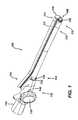
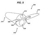
- FIG. 5is a perspective view of an exemplary endoscope having a control wire coupled thereto;
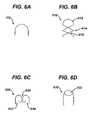
- FIG. 6Ais a top view of the control wire shown in FIG. 1 ;
- FIG. 6Bis a top view of an alternate embodiment of a control wire having an opening formed therein;
- FIG. 6Cis a top view of another embodiment of a control wire having two curved portions formed therein;
- FIG. 6Dis a top view of another embodiment of a control wire having an opening formed therein;
- FIG. 7is a perspective view of the control mechanism of the accessory device shown in FIG. 1 ;
- FIG. 8is a perspective view of the control mechanism shown in FIG. 7 with the knob removed.
- FIG. 9is a cutaway side view of the control mechanism shown in FIG. 7 .
- the present inventiongenerally provides devices and methods useful for manipulating and/or viewing tools at a surgical site. In some cases access to the surgical site can be gained translumenally, e.g., through a body lumen and/or a natural orifice in the body.
- the devices and methodsare particularly useful for manipulating and viewing tools at the working end of a viewing instrument such as an endoscope.
- a viewing instrumentsuch as an endoscope.
- some of the embodiments disclosed hereinwill be described in the context of an endoscopic procedure, the devices and methods are not limited to such applications. They may be used with a wide variety of viewing instruments and other tools. Moreover, they may be used in a wide range of other procedures including non-endoscopic procedures, such as laparoscopic and open procedures, and in virtually any medical procedure now or later in use.
- FIGS. 1-3illustrate one exemplary embodiment of an accessory device 100 .
- the accessory device 100can have a variety of configurations, but in the illustrated embodiment the accessory device 100 includes an insertion member in the form of an elongate sheath 110 and an accessory channel 111 .
- the elongate sheath 110has a distal end 112 with a control wire 118 coupled thereto and a proximal end with a handle 142 and a control mechanism 136 coupled thereto.
- the elongate sheath 110can have a tool such as an endoscope 130 disposed therethrough.
- the distal face 146 of the endoscope 130can have a viewing instrument 124 , for example a lens, one or more lighting elements 126 , 128 , for example lights or fiber optics, and a lumen 116 formed therein for receiving one or more tools, such as viewing instruments, graspers, cutting devices, irrigation devices, and so on.
- the elongate sheath 110can also have a mating element such as a track 134 for mating with a complementary mating element formed on the accessory channel 111 , such as a rail 152 .
- the elongate sheath 110can have one or more control wire lumens 120 , 122 formed therein and extending between the proximal and distal ends 112 , 114 thereof.
- the control wire 118can be slidably disposed in the control wire lumens 120 , 122 .
- the control mechanism 136can be coupled to the control wire 118 and can be adapted to move the control wire 118 , for example, by manipulation of a knob 138 . Movement of the control wire 118 can include, for example, axially sliding the control wire 118 within one or both of the control wire lumens 120 , 122 or axially rotating the control wire 118 . In use, movement of the control wire 118 can be effective to manipulate a tool.
- the toolfor example, can extend distally from the lumen 116 in the endoscope 130 , or from the accessory channel 111 , or the tool can be separate from or spaced apart from the elongate sheath 110 .
- the manipulationcan take many forms, but as one example, a portion of the tool can be pulled into a viewing window of the endoscope 130 .
- the elongate sheath 110can have a variety of configurations, but as shown in FIG. 1 and with more detail in FIGS. 2-3 , the elongate sheath 110 includes an elongate tube or shaft 150 having a lumen 110 ′ formed therein and adapted to receive a tool such as an endoscope 130 therethrough.
- the shaft 150can have a proximal end 114 adapted to remain outside of the body and a distal end 112 adapted to be positioned within the body and adjacent to a surgical site.
- the shaft 150can have any cross-sectional shape, including circles, rectangles, squares, ovals, ellipses, and so on.
- the shaft 150can have an optional end cap 148 , as shown in FIGS. 1-2 .
- the interior of the lumen 110 ′can be of any shape suitable to receive a tool.
- the lumen 110 ′can be adapted to receive a tool such as an endoscope 130 , for example as a covering or sleeve, such that the distal end of the endoscope 130 is disposed at the distal end 112 of the elongate sheath 110 for viewing a surgical site.
- the lumen 110 ′ or portions thereofcan also be rigid and/or have a fixed diameter for passing tools therethrough.
- the elongate sheath 110can also include any number of additional lumens for receiving one or more tools therethrough, including, for example, a tool to be used with an endoscope received through lumen 110 ′.
- the elongate sheath 110 or portions thereofcan be flexible.
- the elongate sheath 110can be made of a flexible material or can include articulating segments placed in desired locations to provide a desired degree of suppleness.
- a flexible elongate sheath 110can be advantageous in some applications, for example, where it is desired to advance the elongate sheath 110 through a tortuous body lumen or to create an elastic fit with a tool received in a lumen.
- a flexible elongate sheath 110can also accommodate articulation or steering of a tool disposed therethrough, such as an endoscope with an articulating distal end.
- the elongate sheath 110can also include one or more control wire lumens 120 , 122 formed therein and extending between the distal end 112 and the proximal end 114 of the elongate sheath 110 .
- the control wire lumens 120 , 122can be adapted to receive one or more control wires 118 therein.
- the control wire lumens 120 , 122 of the elongate sheath 110can be configured to orient the control wire in a desired direction or angle.
- control wire lumens 120 , 122can be bent or angled at the distal end 112 of the elongate sheath 110 such that the control wire exits the elongate sheath 110 at an desired angle.
- the control wire lumens 120 , 122can also include a groove formed therein, or an asymmetrical internal shape such as a ramp structure formed within the interior of the control wire lumen 120 , 122 . as shown, the control wire lumens 120 , 122 are configured such that the control wire 118 extends at an upward angle from the distal end 112 of the elongate sheath 110 .
- control wire lumens 120 , 122can be internal or external to the elongate sheath 110 .
- the elongate sheath 110has control wire lumens integrally formed within the end cap 148 and internal to the elongate sheath 110 .
- control wire lumens 120 , 122can be formed on an exterior surface of the elongate sheath 110 , e.g., as a tube or coil pipe fixedly or removably attached to and extending between proximal and distal ends 112 , 114 of the elongate sheath 110 .
- the elongate sheath 110can also include one or more fixed attachment points for the control wire 118 , any of which can replace or supplement the control wire lumens 120 , 122 .
- An attachment point at the distal end 112 of the elongate sheath 110can replace control lumen 122 , for example, so that the control wire 118 extends from the attachment point to the control wire lumen 120 .
- the accessory channel 111can have a variety of configurations.
- the accessory channel 111is shown as an elongate tube having a proximal end 115 and a distal end 113 .
- the accessory channel 111can have any length, including a same or a similar length as the elongate sheath 110 .
- the accessory channel 111can have virtually any cross-sectional shape, including those shapes mentioned previously with respect to the elongate shaft 110 .
- the accessory channel 111has a circular cross-sectional shape that is smaller in diameter than that of the elongate sheath 110 .
- the accessory channel 111need not have any particular size relative to the elongate sheath 110 and can have a size, including a diameter, width, or other dimension, equal to, greater than or less than that of the elongate sheath 110 .
- the accessory channel 111can have a lumen 111 ′ formed therein for receiving a tool or material therethrough. Multiple lumens are possible, such as was described previously with respect to the elongate sheath 110 .
- the accessory channel 111 or portions thereofcan be flexible or configured with articulating segments, which can be advantageous if the elongate sheath 110 is also flexible, as such an arrangement can allow for the elongate sheath 110 to be flexible even when the accessory channel 111 is mated to the elongate sheath 110 .
- a distal portion of the accessory channelcan also be adapted to be controllably articulated, as described in commonly owned U.S. patent application Ser. No. 11/277,324, entitled “Articulating Endoscopic Accessory Channel,” of James T. Spivey et al., which is hereby incorporated by reference in its entirety.
- the elongate sheath 110 and the accessory channel 111each can have a mating element formed thereon and the mating elements can be adapted to mate with one another.
- the mating elementscan have a variety of configurations, including for example interlocking elements, engaging elements, complementary shapes, sliding members, magnetic elements, spring-loaded retaining members, elastic members, and so on. Such elements can be formed on any portion of or along the entire length of the elongate sheath 110 and/or accessory channel 111 .
- the mating element formed on the elongate sheath 110is a track 134 disposed longitudinally along an outer surface of the elongate sheath 110 between proximal and distal ends 112 , 114 thereof.
- the track 134can have virtually any length, although it can be advantageous if the track 134 is comparable in length to the elongate sheath 110 so that that accessory channel 111 can be securely mated thereto. As shown, the track 134 can define a protruding surface which can be adapted to complement and accommodate the mating element of the accessory channel 111 .
- the mating element of the accessory channel 111is a C-shaped rail 152 .
- the rail 152can be disposed longitudinally on an exterior surface of the accessory channel 111 between proximal and distal ends 113 , 115 thereof.
- the rail 152can have virtually any length, including a length differing from the length of the track 134 .
- the track 134 and the rail 152can be adapted to slide when mated, e.g., to allow the rail 152 to be advanced distally or withdrawn proximally along the track 134 when mated. In such a case, the mating surfaces of the track 134 and the 152 . However, it also possible that the track 134 have a notched, indented, or serrated channel 152 to facilitate movement of the rail 152 between selectable positions. In another embodiment, the track 134 can include an end cap 135 to prevent the distal end of the rail 152 from advancing beyond the distal end of the track 134 .
- one or more of the track 134 and rail 152can be rigid, semi-flexible, or flexible.
- a flexible track 134 and/or rail 152can be advantageous in some applications, such as where the elongate shaft and/or accessory channel are flexible, or where it is desired that the track 134 and the rail 152 have an elastic fit, e.g., where the track 134 elastically encases and/or releases the rail 152 .
- the locations of the track 134 and the rail 152can also be reversed, e.g., the track 134 being disposed on the accessory channel 111 and the rail 152 being disposed on the elongate sheath 110 .
- the accessory device 100need not include an accessory channel 111 .
- the insertion membercan be in the form of an elongate sheath 110 with a control wire 118 coupled thereto, as previously described.
- the elongate sheath 110need not include a mating element such as a track 134 adapted for mating to the accessory channel 111 .
- movement of the control wire 118can be effective to manipulate a tool extending distally from a lumen formed in an endoscope, such as the lumen 116 in the endoscope 130 shown in FIG. 1 .
- an alternate embodiment of an accessory device 500can have an insertion member in the form of an endoscope 500 .
- a lumen 516is formed in the endoscope 500 for receiving a tool therethrough and the distal end 512 of the endoscope 510 has a viewing element 524 and a first and second lighting elements 526 , 528 .
- the endoscope 510has a first and second control wire lumens 520 , 522 formed therein.
- the control wire 518can be moved to manipulate a tool extending distally from the lumen 518 and/or a tool adjacent to the accessory device 500 , such as another tool disposed at the surgical site.
- the accessory device 100 of FIG. 1can also have a control wire 118 .
- the control wire 118can have a variety of configurations, but as shown, the control wire 118 is a solid wire.
- the control wire 118can be flexible or rigid. While a flexible control wire 118 can be advantageous to aid movement of the control wire 118 within the control wire lumens 120 , 122 , a rigid control wire 118 can be advantageous for pushing or otherwise manipulating a tool at a surgical site.
- the control wire 118can be made of any material suitable for use within the body, including stainless steel, and/or a titanium alloy such as nitinol, and can be constructed in a variety of ways.
- control wire 118can be a single wire, or can be formed of braided or twisted wires or fibers.
- the control wire 118can also have a coating or surface treatment for aiding in movement, e.g., a bio-compatible lubricant or a resin such as a Teflon® coating.
- a bio-compatible lubricant or a resinsuch as a Teflon® coating.
- the properties desired in the control wire 118such as its rigidity, flexibility, malleability, and so on can inform the composition and/or configuration of the control wire 118 , as one skilled in the art will recognize.
- the control wire 118can have a variety of shapes formed therein, but as shown in FIG. 1 and in an isolation view in FIG. 6A , the control wire 118 forms an arc between the distal ends of the lumens 120 , 122 and thus a tool can be received between the control wire 118 and the distal end 112 of the elongate sheath 110 .
- the arccan have virtually any size and can be formed by flexing the control wire 118 between the lumens 120 , 122 or the arc can be prefabricated, e.g., such that the control wire 118 retains an arc shape even when removed from the lumens 120 , 122 .
- FIG. 6Billustrates an alternate embodiment of a control wire 610 having a loop 612 formed therein and a cross-hatch pattern 614 .
- the control wire 610can receive a tool therethrough (e.g., through loop 612 ) and can be used to push the tool distally away from the elongate sheath 110 and/or and endoscope 130 received therethrough, as will be discussed in more detail below.
- Each intersection point 616 formed in the control wire 610can be unattached to allow for movement or can be fixedly attached together, for example by adhesive or solder or welding, for stiffening the control wire 610 .
- FIG. 6Cillustrates another embodiment of a control wire 620 having a first hook 622 and an opposing second hook 624 .
- a first toolcan be received in the first hook 622 while a second tool can be received in the second hook 624 .
- the hooks 622 , 624are not connected and can be moved independently; however, the hooks 622 , 624 can be joined at point 626 to allow the hooks 622 , 624 to move in conjunction with one another.
- FIG. 6Dillustrates yet another embodiment of a control wire 630 having a loop 632 formed therein and adapted to receive one or more tools therethrough.
- the control wire 118can have virtually any length.
- the control wire 118can extend from the proximal control mechanism 136 to the distal end 112 of the elongate sheath 110 , extend distally from a first control wire lumen 120 to a second control wire lumen 122 at the distal end 112 of the elongate sheath 110 , and extend back to the proximal control mechanism 136 in a second control wire lumen 122 .
- control wire 118can extend partway along one or more control wire lumens 120 , 122 and have a coupling to the control mechanism 136 via an intermediary rod, cable, or actuator.
- the control wire 118can also be fixed at one or more previously mentioned optional attachment points on the elongate sheath 110 instead of extending through a control wire lumen 120 , 122 .
- the control wire lumens 120 , 122can be configured to direct the control wire 118 at an angle relative to the longitudinal axis of the elongate sheath 110 ; however, the control wire 118 can also be adapted to extend at any angle relative to the accessory device 100 .
- the control wire 118have one or more bends or angles formed therein.
- the extent of the bend or anglecan be of any size, but it can be advantageous if the bend or angle is sufficiently large to allow a tool extending distally from the elongate sheath 110 to be received between the distal end of the elongate sheath 110 and the control wire 118 , or, alternatively, in a loop formed in the control wire 118 .
- the accessory device 100 of FIG. 1can have a control mechanism 136 disposed on a proximal handle 142 .
- the control mechanism 136can be located on any portion of the accessory device 100 , preferably on a portion that remains outside of the body when the accessory device 100 is used, and/or can be integrated into virtually any part of the accessory device 100 .
- the control mechanism 136can be remote to the accessory device 100 , connected via a cable, wireless communications path, computer network, and so on.
- the control mechanism 136can have a wide variety of configurations, but as shown in FIG.
- control mechanism 136has a body 140 including a top cover 704 and a bottom cover 706 and is adapted to mate with a handle 142 at a proximal end of the elongate sheath 110 .
- the body 140can have virtually any size and shape and can include indentations, moldings, handles, bar grips, rings, loops, or other accommodations to allow a user to grasp or operate the control mechanism 136 .
- the control mechanism 136can include any of a wide array of controls, including levers, scissors grips, pivot grips, sliding elements, buttons, dials, switches, pressure sensors, and so on, for manipulating the control wire 118 . As shown in an exemplary embodiment in FIG.
- the control mechanism 136has a rotatable knob 138 with gripping indentations 708 formed thereon.
- the knob 138has been removed to show a first shaft 806 about which the knob 138 can rotate and gears 804 , 808 which can transfer the force of rotation of the knob 138 to the control wire 118 via a second shaft 802 .
- the gears 804 , 808can have virtually any size and gear ratio, the gears 804 , 808 can be chosen in light of the desired force required to actuate the knob 138 and/or the degree of control and sensitivity desired in the control mechanism 136 .
- the position of the knob 138can be adjustable along the rectangular slot 800 shown in FIG. 8 .
- FIG. 9is a cutaway view of the control mechanism 136 and shows the second shaft 802 coupled to a pinion gear 900 disposed between two racks 902 , 904 .
- the upper rack 902is in turn coupled to the control wire 118
- the lower rack 904is coupled to the other end of the control wire 118 .
- one of the racks 902 , 904can be stationary, both ends of the control wire can be coupled to the one of the racks 902 , 904 , etc.
- rotation of the knob 138e.g., can effect axial movement of the control wire 118 within one or more control wire lumens 120 , 122 with a mechanical advantage defined by the gear ratios between the knob 138 and the control wire 118 .
- rotation of the knob 138can move the upper rack 902 distally while moving the bottom rack 904 proximally.
- the knob 138can be coupled to the racks 902 , 904 or the control wire 118 such that movement of the knob 138 along slot 800 , e.g., by longitudinally sliding the knob 138 , can move both racks 902 , 904 proximally or distally at the same time and thus move a portion of the control wire 118 disposed in control wire lumen 120 in the same direction as a portion of the control wire 118 disposed in control wire lumen 122 .
- actuating mechanismscan be used in place of or in addition to the gears and racks shown in FIGS. 8-9 .
- any type and number of gearscan be used, including worm gears, hypoid gears, spur gears, bevel gears, helical gears, annular gears, etc.
- the control mechanism 136can have a ratchet or rack and pawl for moving the control wire 118 , and/or pressure driven or pressure assisted mechanisms, including gas and fluid systems.
- the control mechanism 136can also have actuating rods for pulling and/or pushing the control wire within one or more control wire lumens 120 , 122 , and winding spools for winding the control wire 118 or another cable or wire which can be coupled to the control wire 118 .
- the control mechanism 136can employ electromechanical (e.g., electric motors, magnets, etc.) devices and/or computer-driven or computer-assisted devices for moving the control wire 118 . Any of the aforementioned mechanisms can be arranged to move or axially slide the control wire 118 in one or more control wire lumens 120 , 122 .
- control mechanism 136can be coupled to the control wire 118 in a variety of ways. In FIG. 9 the control mechanism 136 is shown coupled to each of two ends of the control wire 118 . The control mechanism 136 can be adapted to move just one end of the control wire 118 , for example where the opposing send of the control wire 118 is fixedly attached to the elongate sheath 110 or elsewhere.
- the accessory device 100 of FIG. 1can have a variety of other configurations, as one skilled in the art will understand.
- the accessory device 100can have multiple accessory channels, lumens for receiving tools, and/or elongate sheaths.
- the accessory device 100need not receive a tool, and instead the control wire 118 can be adapted to manipulate a tool inserted separately to the surgical site within the body.
- Any of the previously described lumenssuch as accessory channel lumen 111 ′ in FIG. 2 and/or endoscope lumen 116 in FIG. 1 , can receive surgical materials, irrigating fluids, antiseptic agents, or organic substances, etc., therethrough in addition to or instead of tools.
- the accessory device 100can have multiple control wires which can be movable within control wire lumens and/or fixedly attached to the accessory device 100 .
- the control wirescan be arranged to provide multiple loops or arcs at the distal end of the accessory device 100 , and/or can be arranged in a fashion similar to that of a single control wire.
- control wire lumenscan be associated with the accessory channel instead of or in additional to elongate sheath.
- an accessory devicesuch as the accessory device 100 shown in FIG. 1 can be positioned at a surgical site.
- the accessory device 100can be positioned in the body by inserting the distal end of the accessory device 100 into a natural orifice such as the mouth, or through an incision made in the body.
- the accessory device 100can be advanced distally through a body lumen to a desired position.
- the insertionmay be associated with or preceded by any number of procedures to lubricate, flex, shape, measure, steer, turn, rotate, and/or guide the accessory device 100 into the body.
- the insertionmay also be assisted by or performed with a viewing instrument such as an endoscope for showing the path of the accessory device 100 within the body.
- inserting the accessory device 100can include inserting an endoscope through an elongate sheath 110 , and mating an accessory channel 111 to an elongate sheath 110 .
- the rail 152 of the accessory channel 111can be slidably mated to the track 134 of the elongate sheath 110 , and the accessory channel 111 can be advanced to a desired position along the elongate sheath 110 .
- Such matingcan be performed at any time, including before and after part of the accessory device 100 is inserted in the body.
- the accessory channel 111can be unmated, e.g., by sliding the accessory channel 111 proximally along the elongate shaft 110 , and re-mated any number of times to re-introduce the accessory channel 111 or to introduce other accessory channels.
- Surgical tools as well as materialscan be inserted through one or more lumens in the accessory device 100 .
- a toolcan be inserted through the elongate sheath 110 , through a lumen 116 formed in an endoscope 130 disposed in the elongate sheath 110 , and/or through the accessory channel 111 .
- Multiple toolscan be inserted through a single lumen or through separate lumens.
- a toolcan also be inserted into the body separately from the accessory device 100 , for example, not through any lumen formed therein.
- a toolcan be advanced beyond the distal end 112 of the elongate sheath 110 and can be positioned, articulated, and maneuvered at the surgical site, as may be called for by a surgical procedure.
- a surgical toolcan be manipulated by the control wire 118 .
- a wide variety of techniquescan be used. Such manipulations can effect movement of virtually any nature and direction in the surgical tool.
- the toolcan be advanced such that at least a distal end of the tool extends between the control wire 118 and the distal end 112 of the elongate sheath 110 , or at least a distal end of the tool is received in a loop formed in the control wire 118 itself.
- the control wire 118can be used to pull at least a distal end of the tool downwards from the lumen 116 . For example, as shown in FIG.
- the control wire 118can be used to pull at least a distal end of a tool 410 downwards from the accessory channel lumen 111 ′ towards dotted line 400 . Such downward manipulation can bring at least the distal end of the tool within a viewing window of an endoscope.
- the control wire can 118also be used to push at least a distal end of the tool distally away from the accessory device 100 . Pushing a tool can be facilitated with control wires having loops and/or configurations providing suitable rigidity, for example, as previously discussed and illustrated with respect to FIGS. 6B , 6 D.
- the control wire 118can be used to provide a lateral force on the tool.
- Such a lateral forcecan move at least the distal end of the tool laterally with respect to a longitudinal axis of the accessory device 100 .
- a longitudinal axis of the accessory device 100For example, an exemplary longitudinal axis is shown as dotted line 400 in FIG. 4 .
- These and other movements of a surgical toolcan be achieved by manipulating the control wire 118 in a variety of ways. For example, axially sliding the control wire 118 within one or both of the control wire lumens 120 , 122 can lengthen or shorten a distal portion of the control wire 118 and/or can translate the arc formed by the control wire 118 .
- Sliding the control wire 118 in control wire lumen 120 while keeping the control wire 118 stationary in control wire lumen 122can effect asymmetrical movement of the control wire 118 , or can be useful with a control wire having first and second hooks such as was discussed and shown in FIG. 6C .
- the control wire 118can also be turned or rotated in one or both of the control wire lumens 120 , 122 .
- a control mechanism 136can be used to manipulate the control wire 118 .
- a usercan rotate knob 138 to move one end of the control wire distally and move the other end of the control wire 118 proximally, as previously mentioned with respect to FIGS. 8-9 .
- a usercan also move the knob 138 longitudinally along slot 800 to move a portion of the control wire 118 in control wire lumen 120 in the same direction, e.g., proximally or distally, as a portion of the control wire 118 in the control wire lumen 122 .
- Such movementcan translate an arc or a loop formed in the control wire 118 with respect to the accessory device 100 .
- the devices disclosed hereincan also be designed to be disposed of after a single use, or they can be designed to be used multiple times. In either case, however, the device can be reconditioned for reuse after at least one use. Reconditioning can include any combination of the steps of disassembly of the device, followed by cleaning or replacement of particular pieces, and subsequent reassembly.
- the devicecan be disassembled, and any number of the particular pieces or parts of the device can be selectively replaced or removed in any combination.
- the devicecan be reassembled for subsequent use either at a reconditioning facility, or by a surgical team immediately prior to a surgical procedure.
- reconditioning of a devicecan utilize a variety of techniques for disassembly, cleaning and/or replacement, and reassembly. Use of such techniques, and the resulting reconditioned device, are all within the scope of the present application.
- the invention described hereinwill be processed before surgery.
- a new or used toolis obtained and if necessary cleaned.
- the toolcan then be sterilized.
- the toolis placed in a closed and sealed container, such as a plastic or TYVEK bag.
- the container and toolare then placed in a field of radiation that can penetrate the container, such as gamma radiation, x-rays, or high-energy electrons.
- the radiationkills bacteria on the instrument and in the container.
- the sterilized instrumentcan then be stored in the sterile container.
- the sealed containerkeeps the instrument sterile until it is opened in the medical facility. It is preferred that the device is sterilized. This can be done by any number of ways known to those skilled in the art including beta or gamma radiation, ethylene oxide, or steam.
Landscapes
- Health & Medical Sciences (AREA)
- Life Sciences & Earth Sciences (AREA)
- Surgery (AREA)
- Molecular Biology (AREA)
- General Health & Medical Sciences (AREA)
- Biomedical Technology (AREA)
- Heart & Thoracic Surgery (AREA)
- Medical Informatics (AREA)
- Nuclear Medicine, Radiotherapy & Molecular Imaging (AREA)
- Animal Behavior & Ethology (AREA)
- Engineering & Computer Science (AREA)
- Public Health (AREA)
- Veterinary Medicine (AREA)
- Pathology (AREA)
- Physics & Mathematics (AREA)
- Biophysics (AREA)
- Optics & Photonics (AREA)
- Radiology & Medical Imaging (AREA)
- Surgical Instruments (AREA)
Abstract
Description
Claims (20)
Priority Applications (2)
| Application Number | Priority Date | Filing Date | Title |
|---|---|---|---|
| US11/627,542US8007432B2 (en) | 2007-01-26 | 2007-01-26 | Endoscopic accessory control mechanism |
| PCT/US2008/051902WO2008091995A2 (en) | 2007-01-26 | 2008-01-24 | Endoscopic accessory control mechanism |
Applications Claiming Priority (1)
| Application Number | Priority Date | Filing Date | Title |
|---|---|---|---|
| US11/627,542US8007432B2 (en) | 2007-01-26 | 2007-01-26 | Endoscopic accessory control mechanism |
Publications (2)
| Publication Number | Publication Date |
|---|---|
| US20080183035A1 US20080183035A1 (en) | 2008-07-31 |
| US8007432B2true US8007432B2 (en) | 2011-08-30 |
Family
ID=39509590
Family Applications (1)
| Application Number | Title | Priority Date | Filing Date |
|---|---|---|---|
| US11/627,542Expired - Fee RelatedUS8007432B2 (en) | 2007-01-26 | 2007-01-26 | Endoscopic accessory control mechanism |
Country Status (2)
| Country | Link |
|---|---|
| US (1) | US8007432B2 (en) |
| WO (1) | WO2008091995A2 (en) |
Cited By (7)
| Publication number | Priority date | Publication date | Assignee | Title |
|---|---|---|---|---|
| US20090076330A1 (en)* | 2007-09-19 | 2009-03-19 | Fujifilm Corporation | Endoscope |
| US20150031955A1 (en)* | 2009-03-25 | 2015-01-29 | The Cleveland Clinic Foundation | Medical device sheath |
| US10492811B2 (en) | 2017-04-27 | 2019-12-03 | Slatr Surgical Holdings Llc | Rotatable endoscopic instrument |
| US11246566B2 (en)* | 2015-06-26 | 2022-02-15 | B-K Medical Aps | US imaging probe with an instrument channel |
| US11272833B2 (en)* | 2015-03-12 | 2022-03-15 | Keio University | Treatment-instrument insertion aid |
| US11974720B2 (en) | 2020-07-15 | 2024-05-07 | Boston Scientific Scimed, Inc. | Medical device accessory mounting system |
| US12029392B2 (en) | 2021-03-03 | 2024-07-09 | Boston Scientific Scimed, Inc. | Medical device including a medical device management system |
Families Citing this family (22)
| Publication number | Priority date | Publication date | Assignee | Title |
|---|---|---|---|---|
| CA2650474A1 (en) | 2006-04-24 | 2007-11-08 | Synecor, Llc | Natural orifice surgical system |
| US8518024B2 (en) | 2006-04-24 | 2013-08-27 | Transenterix, Inc. | System and method for multi-instrument surgical access using a single access port |
| US9155532B2 (en)* | 2007-05-25 | 2015-10-13 | Cook Medical Technologies Llc | Medical devices, systems and methods for closing perforations |
| US8287469B2 (en) | 2008-01-09 | 2012-10-16 | Ethicon Endo-Surgery, Inc. | Articulating surgical device and method of use |
| US20090182195A1 (en)* | 2008-01-11 | 2009-07-16 | Ethicon Endo-Surgery, Inc. | Endoscopic guide system |
| WO2010042402A1 (en)* | 2008-10-06 | 2010-04-15 | Wilson-Cook Medical, Inc. | Endcap for safely deploying tissue anchors |
| US20100125168A1 (en)* | 2008-11-14 | 2010-05-20 | Ethicon Endo-Surgery, Inc. | Methods and devices for endoscope control in a body cavity |
| US8388520B2 (en) | 2009-02-25 | 2013-03-05 | Ethicon Endo-Surgery, Inc. | Shape control endoscope |
| DE102009015392A1 (en) | 2009-03-20 | 2010-09-23 | Karl Storz Gmbh & Co. Kg | Medical instrument, in particular hysteroscope |
| DE102009060718A1 (en)* | 2009-12-29 | 2011-06-30 | Richard Wolf GmbH, 75438 | Endoscopic instrument |
| DE202010018546U1 (en) | 2010-05-11 | 2017-08-07 | Lohmann & Rauscher Gmbh & Co. Kg | External insertion aid for endoscopes |
| US20120088968A1 (en)* | 2010-10-11 | 2012-04-12 | Epic Medical Inc. | Methods and devices for visualization and access |
| GB201018532D0 (en)* | 2010-11-03 | 2010-12-15 | Surgical Innovations Ltd | Handle and surgical instrument |
| US20140364866A1 (en)* | 2012-01-06 | 2014-12-11 | University Of Louisville Research Foundation, Inc. | Endoscopic snare device |
| HK1244652A1 (en) | 2014-10-20 | 2018-08-17 | Research Development International Corporation | Steerable micro-endoscope |
| CN107205619B (en)* | 2015-01-20 | 2020-04-07 | 奥林巴斯株式会社 | Insertion aid and medical device |
| CN110198654A (en)* | 2017-01-20 | 2019-09-03 | 波士顿科学国际有限公司 | System for minimal invasive operation |
| EP3494861B1 (en)* | 2017-12-05 | 2024-02-28 | Erbe Elektromedizin GmbH | Device with a working channel guide element |
| US12082839B2 (en) | 2018-03-25 | 2024-09-10 | T.A.G. Medical Products Corporation Ltd. | Working channel device |
| US11478234B2 (en)* | 2018-03-25 | 2022-10-25 | T.A.G. Medical Products Corporation Ltd. | Working channel device for an endoscopic tool |
| WO2020031378A1 (en)* | 2018-08-10 | 2020-02-13 | オリンパス株式会社 | Endoscope |
| DE102020213617B4 (en) | 2020-10-29 | 2024-04-18 | Loai Brijawi | Device for applying rubber rings in the human body |
Citations (109)
| Publication number | Priority date | Publication date | Assignee | Title |
|---|---|---|---|---|
| US1891054A (en)* | 1931-03-28 | 1932-12-13 | Louis K Pitman | Surgical instrument |
| US3924608A (en) | 1973-05-23 | 1975-12-09 | Olympus Optical Co | Endoscope |
| US4454887A (en) | 1981-04-15 | 1984-06-19 | Krueger Christian | Medical instruments for introduction into the respiratory tract of a patient |
| US4520817A (en) | 1980-02-05 | 1985-06-04 | United States Surgical Corporation | Surgical instruments |
| GB2109241B (en) | 1981-09-11 | 1985-09-04 | Fuji Photo Optical Co Ltd | Endoscope together with another medical appliance |
| US4646722A (en) | 1984-12-10 | 1987-03-03 | Opielab, Inc. | Protective endoscope sheath and method of installing same |
| US4697576A (en) | 1986-02-18 | 1987-10-06 | Welch Allyn, Inc. | Endoscope forceps elevator cable seal |
| US5025778A (en) | 1990-03-26 | 1991-06-25 | Opielab, Inc. | Endoscope with potential channels and method of using the same |
| US5040715A (en) | 1989-05-26 | 1991-08-20 | United States Surgical Corporation | Apparatus and method for placing staples in laparoscopic or endoscopic procedures |
| US5201908A (en) | 1991-06-10 | 1993-04-13 | Endomedical Technologies, Inc. | Sheath for protecting endoscope from contamination |
| US5211649A (en) | 1987-02-10 | 1993-05-18 | Vaso Products Australia Pty. Limited | Venous cuff applicator, cartridge and cuff |
| US5217001A (en) | 1991-12-09 | 1993-06-08 | Nakao Naomi L | Endoscope sheath and related method |
| US5259366A (en) | 1992-11-03 | 1993-11-09 | Boris Reydel | Method of using a catheter-sleeve assembly for an endoscope |
| GB2272159A (en) | 1992-11-10 | 1994-05-11 | Andreas G Constantinides | Surgical/diagnostic aid |
| EP0634144A1 (en) | 1993-07-15 | 1995-01-18 | Ethicon, Inc. | An Endoscopic instrument having a torsionally stiff drive shaft for applying fasteners to tissue |
| US5383880A (en) | 1992-01-17 | 1995-01-24 | Ethicon, Inc. | Endoscopic surgical system with sensing means |
| US5386817A (en) | 1991-06-10 | 1995-02-07 | Endomedical Technologies, Inc. | Endoscope sheath and valve system |
| US5400770A (en) | 1992-01-15 | 1995-03-28 | Nakao; Naomi L. | Device utilizable with endoscope and related method |
| US5431322A (en) | 1991-10-18 | 1995-07-11 | United States Surgical Corporation | Self contained gas powered surgical apparatus |
| US5460168A (en)* | 1992-12-25 | 1995-10-24 | Olympus Optical Co., Ltd. | Endoscope cover assembly and cover-system endoscope |
| US5482197A (en) | 1991-10-18 | 1996-01-09 | United States Surgical Corporation | Articulating surgical cartridge assembly |
| US5489256A (en) | 1992-09-01 | 1996-02-06 | Adair; Edwin L. | Sterilizable endoscope with separable disposable tube assembly |
| US5503616A (en) | 1991-06-10 | 1996-04-02 | Endomedical Technologies, Inc. | Collapsible access channel system |
| US5630782A (en) | 1992-09-01 | 1997-05-20 | Adair; Edwin L. | Sterilizable endoscope with separable auxiliary assembly |
| US5643175A (en) | 1992-09-01 | 1997-07-01 | Adair; Edwin L. | Sterilizable endoscope with separable disposable tube assembly |
| US5651491A (en) | 1995-10-27 | 1997-07-29 | United States Surgical Corporation | Surgical stapler having interchangeable loading units |
| EP0552423B1 (en) | 1991-10-18 | 1998-01-07 | United States Surgical Corporation | Self contained gas powered surgical apparatus |
| US5715988A (en) | 1995-08-14 | 1998-02-10 | United States Surgical Corporation | Surgical stapler with lockout mechanism |
| US5749889A (en) | 1996-02-13 | 1998-05-12 | Imagyn Medical, Inc. | Method and apparatus for performing biopsy |
| US5762256A (en) | 1995-08-28 | 1998-06-09 | United States Surgical Corporation | Surgical stapler |
| US5779130A (en) | 1994-08-05 | 1998-07-14 | United States Surgical Corporation | Self-contained powered surgical apparatus |
| US5782396A (en) | 1995-08-28 | 1998-07-21 | United States Surgical Corporation | Surgical stapler |
| US5823971A (en)* | 1993-10-29 | 1998-10-20 | Boston Scientific Corporation | Multiple biopsy sampling coring device |
| US5865361A (en) | 1997-09-23 | 1999-02-02 | United States Surgical Corporation | Surgical stapling apparatus |
| US5944654A (en) | 1996-11-14 | 1999-08-31 | Vista Medical Technologies, Inc. | Endoscope with replaceable irrigation tube |
| US5954259A (en) | 1994-08-05 | 1999-09-21 | United States Surgical Corporation | Self-contained powered surgical apparatus for applying surgical fasteners |
| JP2000033071A (en) | 1998-07-17 | 2000-02-02 | Olympus Optical Co Ltd | Endoscope therapeutic device |
| US6032849A (en) | 1995-08-28 | 2000-03-07 | United States Surgical | Surgical stapler |
| US6071233A (en) | 1997-10-31 | 2000-06-06 | Olympus Optical Co., Ltd. | Endoscope |
| JP2000171730A (en) | 1998-12-08 | 2000-06-23 | Olympus Optical Co Ltd | Battery type portable endoscopic device |
| US6109500A (en) | 1996-10-04 | 2000-08-29 | United States Surgical Corporation | Lockout mechanism for a surgical stapler |
| JP2000325303A (en) | 1999-05-17 | 2000-11-28 | Olympus Optical Co Ltd | Endoscopic therapeutic device |
| US6179776B1 (en) | 1999-03-12 | 2001-01-30 | Scimed Life Systems, Inc. | Controllable endoscopic sheath apparatus and related method of use |
| US6264087B1 (en) | 1999-07-12 | 2001-07-24 | Powermed, Inc. | Expanding parallel jaw device for use with an electromechanical driver device |
| US6315184B1 (en) | 1999-06-02 | 2001-11-13 | Powermed, Inc. | Stapling device for use with an electromechanical driver device for use with anastomosing, stapling, and resecting instruments |
| US6352503B1 (en) | 1998-07-17 | 2002-03-05 | Olympus Optical Co., Ltd. | Endoscopic surgery apparatus |
| US20020049454A1 (en) | 1999-06-02 | 2002-04-25 | Whitman Michael P. | Electro-mechanical surgical device |
| JP2002143078A (en) | 2000-11-08 | 2002-05-21 | Olympus Optical Co Ltd | Outside tube for endoscope |
| US20020107530A1 (en) | 2001-02-02 | 2002-08-08 | Sauer Jude S. | System for endoscopic suturing |
| US6443973B1 (en) | 1999-06-02 | 2002-09-03 | Power Medical Interventions, Inc. | Electromechanical driver device for use with anastomosing, stapling, and resecting instruments |
| US6458076B1 (en) | 2000-02-01 | 2002-10-01 | 5 Star Medical | Multi-lumen medical device |
| US20020183591A1 (en) | 2001-02-06 | 2002-12-05 | Nobuyuki Matsuura | Endoscopic system and method for positioning an indwelling tube |
| US6522101B2 (en) | 1999-12-10 | 2003-02-18 | Stryker Corporation | Rechargeable battery with memory that contains charging sequence data |
| EP1284120A1 (en) | 2001-08-09 | 2003-02-19 | Ingo F. Prof. Dr. Herrmann | Disposable endoscope sheath |
| US20030036679A1 (en) | 2001-08-16 | 2003-02-20 | Syntheon, Llc | Methods and apparatus for delivering a medical instrument over an endoscope while the endoscope is in a body lumen |
| US6527753B2 (en) | 2000-02-29 | 2003-03-04 | Olympus Optical Co., Ltd. | Endoscopic treatment system |
| US20030130561A1 (en) | 2000-07-24 | 2003-07-10 | Takayuki Suzuki | Endoscope and endoscopic instrument and method using same |
| US20030130564A1 (en) | 2002-01-04 | 2003-07-10 | Stephen Martone | Endoscope assemblies having working channels with reduced bending and stretching resistance |
| US20030176880A1 (en) | 2002-03-15 | 2003-09-18 | Long Gary L. | Biopsy forceps device and method |
| US20030176766A1 (en) | 2002-03-15 | 2003-09-18 | Long Gary L. | Apparatus for guiding an instrument used with an endoscope |
| US20030176767A1 (en) | 2002-03-15 | 2003-09-18 | Long Gary L. | Method for controlling position of medical instruments |
| EP1152685B1 (en) | 1999-02-15 | 2003-10-29 | Ingo F. Herrmann | Deformable fiberscope with a displaceable supplementary device |
| US20030208219A1 (en) | 2001-05-18 | 2003-11-06 | Aznoian Harold M. | Steerable biliary catheter |
| US6699180B2 (en) | 2000-10-11 | 2004-03-02 | Olympus Corporation | Endoscopic hood |
| EP1402837A1 (en) | 2002-09-18 | 2004-03-31 | Ethicon Endo-Surgery, Inc. | Endoscopic ablation system with a plurality of electrodes |
| US6716233B1 (en) | 1999-06-02 | 2004-04-06 | Power Medical Interventions, Inc. | Electromechanical driver and remote surgical instrument attachment having computer assisted control capabilities |
| WO2004047626A1 (en) | 2002-11-22 | 2004-06-10 | Jiang, Shoumei | Endoscope assembly with disposable sheath |
| US20040133075A1 (en) | 2002-08-06 | 2004-07-08 | Nobuyuki Motoki | Endoscope apparatus |
| US6790173B2 (en) | 2002-06-13 | 2004-09-14 | Usgi Medical, Inc. | Shape lockable apparatus and method for advancing an instrument through unsupported anatomy |
| US6793652B1 (en) | 1999-06-02 | 2004-09-21 | Power Medical Interventions, Inc. | Electro-mechanical surgical device |
| EP1459695A1 (en) | 2003-03-21 | 2004-09-22 | Ethicon Endo-Surgery, Inc. | Medical device with improved wall construction |
| US6808491B2 (en) | 2001-05-21 | 2004-10-26 | Syntheon, Llc | Methods and apparatus for on-endoscope instruments having end effectors and combinations of on-endoscope and through-endoscope instruments |
| US20040215058A1 (en) | 2002-09-06 | 2004-10-28 | Zirps Christopher T | Endoscopic accessory mounting adaptor |
| US20040230095A1 (en) | 2003-05-16 | 2004-11-18 | David Stefanchik | Medical apparatus for use with an endoscope |
| US20040230097A1 (en) | 2003-05-16 | 2004-11-18 | David Stefanchik | Endcap for use with an endoscope |
| US6824509B2 (en)* | 2001-07-23 | 2004-11-30 | Olympus Corporation | Endoscope |
| WO2004105593A1 (en) | 2003-05-29 | 2004-12-09 | Kiyoteru Shima | External forceps channel device for endoscope |
| US20050049455A1 (en) | 2000-04-17 | 2005-03-03 | Olympus Corporation | Endoscope and endoscope system thereof |
| JP2005131107A (en) | 2003-10-30 | 2005-05-26 | Olympus Corp | External channel and endoscope apparatus equipped with the same |
| JP2005131164A (en) | 2003-10-31 | 2005-05-26 | Olympus Corp | External channel for endoscope |
| JP2005131173A (en) | 2003-10-31 | 2005-05-26 | Olympus Corp | Externally mounted channel for endoscope |
| JP2005131163A (en) | 2003-10-31 | 2005-05-26 | Olympus Corp | External channel for endoscope |
| JP2005131211A (en) | 2003-10-31 | 2005-05-26 | Olympus Corp | Externally mounted channel for endoscope |
| JP2005131212A (en) | 2003-10-31 | 2005-05-26 | Olympus Corp | External channel for endoscope and endoscope device |
| JP2005137423A (en) | 2003-11-04 | 2005-06-02 | Olympus Corp | External channel for endoscope and branch member for external channel |
| US20050119524A1 (en) | 2002-08-07 | 2005-06-02 | Olympus Optical Co., Ltd. | Endoscopic treatment system |
| US20050119525A1 (en) | 2003-11-27 | 2005-06-02 | Olympus Corporation | Insertion auxiliary implement |
| US20050124855A1 (en) | 2000-04-03 | 2005-06-09 | Ross Jaffe | Endoscope having a guide tube |
| US20050131278A1 (en) | 2003-12-16 | 2005-06-16 | Olympus Winter & Ibe Gmbh | Endoscope |
| US20050137454A1 (en) | 2002-06-13 | 2005-06-23 | Usgi Medical Corp. | Shape lockable apparatus and method for advancing an instrument through unsupported anatomy |
| US20050149067A1 (en) | 2002-01-30 | 2005-07-07 | Olympus Corporation | Endoscopic suturing system |
| US20050154258A1 (en) | 2000-04-03 | 2005-07-14 | Tartaglia Joseph M. | Endoscope with adjacently positioned guiding apparatus |
| US20050177181A1 (en) | 2002-11-01 | 2005-08-11 | Jonathan Kagan | Devices and methods for treating morbid obesity |
| US20050222495A1 (en) | 2004-04-02 | 2005-10-06 | Olympus Corporation | Medical system with over-tube |
| US20050234297A1 (en) | 2004-04-15 | 2005-10-20 | Wilson-Cook Medical, Inc. | Endoscopic surgical access devices and methods of articulating an external accessory channel |
| EP0880338B1 (en) | 1996-02-13 | 2005-10-26 | ConMed Corporation | Surgical access device |
| JP2005304586A (en) | 2004-04-19 | 2005-11-04 | Pentax Corp | The tip of a side-viewing endoscope |
| US20050256374A1 (en) | 2004-05-14 | 2005-11-17 | Ethicon Endo-Surgery, Inc. | Medical instrument having a guidewire and an add-to catheter |
| US20060020247A1 (en) | 2002-11-01 | 2006-01-26 | Jonathan Kagan | Devices and methods for attaching an endolumenal gastrointestinal implant |
| US7029435B2 (en) | 2003-10-16 | 2006-04-18 | Granit Medical Innovation, Llc | Endoscope having multiple working segments |
| US20060235271A1 (en) | 2005-04-15 | 2006-10-19 | Wilson-Cook Medical Inc. | Endoscopic apparatus having an improved elevator |
| US20060258903A1 (en) | 2005-05-13 | 2006-11-16 | David Stefanchik | Method of inserting a feeding tube |
| US20060258904A1 (en) | 2005-05-13 | 2006-11-16 | David Stefanchik | Feeding tube and track |
| US20060259010A1 (en) | 2005-05-13 | 2006-11-16 | David Stefanchik | Feeding tube |
| EP1400214B8 (en) | 2002-09-18 | 2006-12-20 | Ethicon Endo-Surgery, Inc. | Endoscopic ablation system with a distally mounted image sensor |
| US7226410B2 (en)* | 2002-12-05 | 2007-06-05 | Ethicon-Endo Surgery, Inc. | Locally-propelled, intraluminal device with cable loop track and method of use |
| US7351202B2 (en)* | 2002-12-05 | 2008-04-01 | Ethicon Endo-Surgery, Inc. | Medical device with track and method of use |
| EP1593337B1 (en) | 2003-02-11 | 2008-08-13 | Olympus Corporation | Overtube |
| EP1607050B1 (en) | 2004-06-14 | 2009-12-02 | Ethicon Endo-Surgery, Inc. | Clip ejector for endoscopic clip applier |
- 2007
- 2007-01-26USUS11/627,542patent/US8007432B2/ennot_activeExpired - Fee Related
- 2008
- 2008-01-24WOPCT/US2008/051902patent/WO2008091995A2/enactiveApplication Filing
Patent Citations (142)
| Publication number | Priority date | Publication date | Assignee | Title |
|---|---|---|---|---|
| US1891054A (en)* | 1931-03-28 | 1932-12-13 | Louis K Pitman | Surgical instrument |
| US3924608A (en) | 1973-05-23 | 1975-12-09 | Olympus Optical Co | Endoscope |
| US4520817A (en) | 1980-02-05 | 1985-06-04 | United States Surgical Corporation | Surgical instruments |
| US4454887A (en) | 1981-04-15 | 1984-06-19 | Krueger Christian | Medical instruments for introduction into the respiratory tract of a patient |
| GB2109241B (en) | 1981-09-11 | 1985-09-04 | Fuji Photo Optical Co Ltd | Endoscope together with another medical appliance |
| US4646722A (en) | 1984-12-10 | 1987-03-03 | Opielab, Inc. | Protective endoscope sheath and method of installing same |
| US4697576A (en) | 1986-02-18 | 1987-10-06 | Welch Allyn, Inc. | Endoscope forceps elevator cable seal |
| US5211649A (en) | 1987-02-10 | 1993-05-18 | Vaso Products Australia Pty. Limited | Venous cuff applicator, cartridge and cuff |
| US5040715B1 (en) | 1989-05-26 | 1994-04-05 | United States Surgical Corp | Apparatus and method for placing staples in laparoscopic or endoscopic procedures |
| US5040715A (en) | 1989-05-26 | 1991-08-20 | United States Surgical Corporation | Apparatus and method for placing staples in laparoscopic or endoscopic procedures |
| US5025778A (en) | 1990-03-26 | 1991-06-25 | Opielab, Inc. | Endoscope with potential channels and method of using the same |
| US5386817A (en) | 1991-06-10 | 1995-02-07 | Endomedical Technologies, Inc. | Endoscope sheath and valve system |
| US5201908A (en) | 1991-06-10 | 1993-04-13 | Endomedical Technologies, Inc. | Sheath for protecting endoscope from contamination |
| US5503616A (en) | 1991-06-10 | 1996-04-02 | Endomedical Technologies, Inc. | Collapsible access channel system |
| US5431322A (en) | 1991-10-18 | 1995-07-11 | United States Surgical Corporation | Self contained gas powered surgical apparatus |
| EP0552423B1 (en) | 1991-10-18 | 1998-01-07 | United States Surgical Corporation | Self contained gas powered surgical apparatus |
| US5482197A (en) | 1991-10-18 | 1996-01-09 | United States Surgical Corporation | Articulating surgical cartridge assembly |
| US5217001A (en) | 1991-12-09 | 1993-06-08 | Nakao Naomi L | Endoscope sheath and related method |
| US5353783A (en) | 1991-12-09 | 1994-10-11 | Nakao Naomi L | Endoscopic method using sheath |
| US5400770A (en) | 1992-01-15 | 1995-03-28 | Nakao; Naomi L. | Device utilizable with endoscope and related method |
| US5518164A (en) | 1992-01-17 | 1996-05-21 | Ethicon, Inc. | Endoscopic surgical system with sensing means |
| US5383880A (en) | 1992-01-17 | 1995-01-24 | Ethicon, Inc. | Endoscopic surgical system with sensing means |
| US5518163A (en) | 1992-01-17 | 1996-05-21 | Ethicon, Inc. | Endoscopic surgical system with sensing means |
| US5433721A (en) | 1992-01-17 | 1995-07-18 | Ethicon, Inc. | Endoscopic instrument having a torsionally stiff drive shaft for applying fasteners to tissue |
| EP0552050B1 (en) | 1992-01-17 | 2000-05-10 | Ethicon, Inc. | Endoscopic surgical system with sensing means |
| US5667517A (en) | 1992-01-17 | 1997-09-16 | Ethicon, Inc. | Endoscopic surgical system with sensing means |
| US5489256A (en) | 1992-09-01 | 1996-02-06 | Adair; Edwin L. | Sterilizable endoscope with separable disposable tube assembly |
| US5630782A (en) | 1992-09-01 | 1997-05-20 | Adair; Edwin L. | Sterilizable endoscope with separable auxiliary assembly |
| US5643175A (en) | 1992-09-01 | 1997-07-01 | Adair; Edwin L. | Sterilizable endoscope with separable disposable tube assembly |
| US5259366A (en) | 1992-11-03 | 1993-11-09 | Boris Reydel | Method of using a catheter-sleeve assembly for an endoscope |
| GB2272159A (en) | 1992-11-10 | 1994-05-11 | Andreas G Constantinides | Surgical/diagnostic aid |
| US5460168A (en)* | 1992-12-25 | 1995-10-24 | Olympus Optical Co., Ltd. | Endoscope cover assembly and cover-system endoscope |
| EP0634144A1 (en) | 1993-07-15 | 1995-01-18 | Ethicon, Inc. | An Endoscopic instrument having a torsionally stiff drive shaft for applying fasteners to tissue |
| US5823971A (en)* | 1993-10-29 | 1998-10-20 | Boston Scientific Corporation | Multiple biopsy sampling coring device |
| US5954259A (en) | 1994-08-05 | 1999-09-21 | United States Surgical Corporation | Self-contained powered surgical apparatus for applying surgical fasteners |
| US5779130A (en) | 1994-08-05 | 1998-07-14 | United States Surgical Corporation | Self-contained powered surgical apparatus |
| EP1426012B1 (en) | 1994-10-07 | 2007-10-17 | United States Surgical Corporation | Self-contained powered surgical apparatus |
| EP0705570B1 (en) | 1994-10-07 | 2004-04-28 | United States Surgical Corporation | Self-contained powered surgical apparatus |
| US5715988A (en) | 1995-08-14 | 1998-02-10 | United States Surgical Corporation | Surgical stapler with lockout mechanism |
| US6032849A (en) | 1995-08-28 | 2000-03-07 | United States Surgical | Surgical stapler |
| US5782396A (en) | 1995-08-28 | 1998-07-21 | United States Surgical Corporation | Surgical stapler |
| US5762256A (en) | 1995-08-28 | 1998-06-09 | United States Surgical Corporation | Surgical stapler |
| US5651491A (en) | 1995-10-27 | 1997-07-29 | United States Surgical Corporation | Surgical stapler having interchangeable loading units |
| US5749889A (en) | 1996-02-13 | 1998-05-12 | Imagyn Medical, Inc. | Method and apparatus for performing biopsy |
| EP0880338B1 (en) | 1996-02-13 | 2005-10-26 | ConMed Corporation | Surgical access device |
| US6109500A (en) | 1996-10-04 | 2000-08-29 | United States Surgical Corporation | Lockout mechanism for a surgical stapler |
| US5944654A (en) | 1996-11-14 | 1999-08-31 | Vista Medical Technologies, Inc. | Endoscope with replaceable irrigation tube |
| US5865361A (en) | 1997-09-23 | 1999-02-02 | United States Surgical Corporation | Surgical stapling apparatus |
| US6071233A (en) | 1997-10-31 | 2000-06-06 | Olympus Optical Co., Ltd. | Endoscope |
| US6352503B1 (en) | 1998-07-17 | 2002-03-05 | Olympus Optical Co., Ltd. | Endoscopic surgery apparatus |
| JP2000033071A (en) | 1998-07-17 | 2000-02-02 | Olympus Optical Co Ltd | Endoscope therapeutic device |
| JP2000171730A (en) | 1998-12-08 | 2000-06-23 | Olympus Optical Co Ltd | Battery type portable endoscopic device |
| US6878106B1 (en) | 1999-02-15 | 2005-04-12 | Ingo F. Herrmann | Deformable fiberscope with a displaceable supplementary device |
| EP1152685B1 (en) | 1999-02-15 | 2003-10-29 | Ingo F. Herrmann | Deformable fiberscope with a displaceable supplementary device |
| US6761685B2 (en) | 1999-03-12 | 2004-07-13 | Scimed Life Systems, Inc. | Controllable endoscopic sheath apparatus and related method of use |
| US6179776B1 (en) | 1999-03-12 | 2001-01-30 | Scimed Life Systems, Inc. | Controllable endoscopic sheath apparatus and related method of use |
| EP1161174B1 (en) | 1999-03-12 | 2006-05-17 | Boston Scientific Limited | Controllable endoscopic sheath |
| US7070559B2 (en) | 1999-03-12 | 2006-07-04 | Scimed Life Systems, Inc. | Controllable endoscopic sheath apparatus and related method of use |
| JP2000325303A (en) | 1999-05-17 | 2000-11-28 | Olympus Optical Co Ltd | Endoscopic therapeutic device |
| US6315184B1 (en) | 1999-06-02 | 2001-11-13 | Powermed, Inc. | Stapling device for use with an electromechanical driver device for use with anastomosing, stapling, and resecting instruments |
| US6716233B1 (en) | 1999-06-02 | 2004-04-06 | Power Medical Interventions, Inc. | Electromechanical driver and remote surgical instrument attachment having computer assisted control capabilities |
| US6846307B2 (en) | 1999-06-02 | 2005-01-25 | Power Medical Interventions, Inc. | Electro-mechanical surgical device |
| US6846308B2 (en) | 1999-06-02 | 2005-01-25 | Power Medical Interventions, Inc. | Electro-mechanical surgical device |
| US6846309B2 (en) | 1999-06-02 | 2005-01-25 | Power Medical Interventions, Inc. | Electro-mechanical surgical device |
| US6793652B1 (en) | 1999-06-02 | 2004-09-21 | Power Medical Interventions, Inc. | Electro-mechanical surgical device |
| US20020049454A1 (en) | 1999-06-02 | 2002-04-25 | Whitman Michael P. | Electro-mechanical surgical device |
| US6443973B1 (en) | 1999-06-02 | 2002-09-03 | Power Medical Interventions, Inc. | Electromechanical driver device for use with anastomosing, stapling, and resecting instruments |
| US6264087B1 (en) | 1999-07-12 | 2001-07-24 | Powermed, Inc. | Expanding parallel jaw device for use with an electromechanical driver device |
| US6522101B2 (en) | 1999-12-10 | 2003-02-18 | Stryker Corporation | Rechargeable battery with memory that contains charging sequence data |
| US6458076B1 (en) | 2000-02-01 | 2002-10-01 | 5 Star Medical | Multi-lumen medical device |
| US6527753B2 (en) | 2000-02-29 | 2003-03-04 | Olympus Optical Co., Ltd. | Endoscopic treatment system |
| US6984203B2 (en) | 2000-04-03 | 2006-01-10 | Neoguide Systems, Inc. | Endoscope with adjacently positioned guiding apparatus |
| US20050124855A1 (en) | 2000-04-03 | 2005-06-09 | Ross Jaffe | Endoscope having a guide tube |
| US20060015009A1 (en) | 2000-04-03 | 2006-01-19 | Ross Jaffe | Endoscope having a guide tube |
| US20050154258A1 (en) | 2000-04-03 | 2005-07-14 | Tartaglia Joseph M. | Endoscope with adjacently positioned guiding apparatus |
| US7087010B2 (en) | 2000-04-17 | 2006-08-08 | Olympus Corporation | Endoscope and endoscope system thereof |
| US20050049455A1 (en) | 2000-04-17 | 2005-03-03 | Olympus Corporation | Endoscope and endoscope system thereof |
| US20030130561A1 (en) | 2000-07-24 | 2003-07-10 | Takayuki Suzuki | Endoscope and endoscopic instrument and method using same |
| US6699180B2 (en) | 2000-10-11 | 2004-03-02 | Olympus Corporation | Endoscopic hood |
| JP2002143078A (en) | 2000-11-08 | 2002-05-21 | Olympus Optical Co Ltd | Outside tube for endoscope |
| US6997931B2 (en) | 2001-02-02 | 2006-02-14 | Lsi Solutions, Inc. | System for endoscopic suturing |
| US20050165419A1 (en) | 2001-02-02 | 2005-07-28 | Sauer Jude S. | System for endoscopic suturing |
| US20020107530A1 (en) | 2001-02-02 | 2002-08-08 | Sauer Jude S. | System for endoscopic suturing |
| US6786864B2 (en) | 2001-02-06 | 2004-09-07 | Olympus Corporation | Endoscopic system and method for positioning an indwelling tube |
| US20020183591A1 (en) | 2001-02-06 | 2002-12-05 | Nobuyuki Matsuura | Endoscopic system and method for positioning an indwelling tube |
| US20030208219A1 (en) | 2001-05-18 | 2003-11-06 | Aznoian Harold M. | Steerable biliary catheter |
| US6808491B2 (en) | 2001-05-21 | 2004-10-26 | Syntheon, Llc | Methods and apparatus for on-endoscope instruments having end effectors and combinations of on-endoscope and through-endoscope instruments |
| US6824509B2 (en)* | 2001-07-23 | 2004-11-30 | Olympus Corporation | Endoscope |
| EP1284120A1 (en) | 2001-08-09 | 2003-02-19 | Ingo F. Prof. Dr. Herrmann | Disposable endoscope sheath |
| DE10139153A1 (en) | 2001-08-09 | 2003-02-27 | Ingo F Herrmann | Disposable endoscope sheath |
| US20030195387A1 (en) | 2001-08-16 | 2003-10-16 | Syntheon, Llc | Methods and appartus for delivering a medical instrument over an endoscope while the endoscope is in a body lumen |
| US6569085B2 (en) | 2001-08-16 | 2003-05-27 | Syntheon, Llc | Methods and apparatus for delivering a medical instrument over an endoscope while the endoscope is in a body lumen |
| US20030036679A1 (en) | 2001-08-16 | 2003-02-20 | Syntheon, Llc | Methods and apparatus for delivering a medical instrument over an endoscope while the endoscope is in a body lumen |
| US20060079735A1 (en) | 2002-01-04 | 2006-04-13 | Stephen Martone | Endoscope assemblies having working channels with reduced bending and stretching resistance |
| US6740030B2 (en) | 2002-01-04 | 2004-05-25 | Vision Sciences, Inc. | Endoscope assemblies having working channels with reduced bending and stretching resistance |
| US7056284B2 (en) | 2002-01-04 | 2006-06-06 | Vision Sciences, Inc. | Endoscope assemblies having working channels with reduced bending and stretching resistance |
| US20030130564A1 (en) | 2002-01-04 | 2003-07-10 | Stephen Martone | Endoscope assemblies having working channels with reduced bending and stretching resistance |
| US20050149067A1 (en) | 2002-01-30 | 2005-07-07 | Olympus Corporation | Endoscopic suturing system |
| US20030176766A1 (en) | 2002-03-15 | 2003-09-18 | Long Gary L. | Apparatus for guiding an instrument used with an endoscope |
| US20030176880A1 (en) | 2002-03-15 | 2003-09-18 | Long Gary L. | Biopsy forceps device and method |
| US20030176767A1 (en) | 2002-03-15 | 2003-09-18 | Long Gary L. | Method for controlling position of medical instruments |
| US20050137455A1 (en) | 2002-06-13 | 2005-06-23 | Usgi Medical Corp. | Shape lockable apparatus and method for advancing an instrument through unsupported anatomy |
| US20050137454A1 (en) | 2002-06-13 | 2005-06-23 | Usgi Medical Corp. | Shape lockable apparatus and method for advancing an instrument through unsupported anatomy |
| US6790173B2 (en) | 2002-06-13 | 2004-09-14 | Usgi Medical, Inc. | Shape lockable apparatus and method for advancing an instrument through unsupported anatomy |
| US20040133075A1 (en) | 2002-08-06 | 2004-07-08 | Nobuyuki Motoki | Endoscope apparatus |
| US20050119524A1 (en) | 2002-08-07 | 2005-06-02 | Olympus Optical Co., Ltd. | Endoscopic treatment system |
| US20040215058A1 (en) | 2002-09-06 | 2004-10-28 | Zirps Christopher T | Endoscopic accessory mounting adaptor |
| EP1400214B8 (en) | 2002-09-18 | 2006-12-20 | Ethicon Endo-Surgery, Inc. | Endoscopic ablation system with a distally mounted image sensor |
| EP1402837A1 (en) | 2002-09-18 | 2004-03-31 | Ethicon Endo-Surgery, Inc. | Endoscopic ablation system with a plurality of electrodes |
| US20060020247A1 (en) | 2002-11-01 | 2006-01-26 | Jonathan Kagan | Devices and methods for attaching an endolumenal gastrointestinal implant |
| US20050177181A1 (en) | 2002-11-01 | 2005-08-11 | Jonathan Kagan | Devices and methods for treating morbid obesity |
| WO2004047626A1 (en) | 2002-11-22 | 2004-06-10 | Jiang, Shoumei | Endoscope assembly with disposable sheath |
| US7351202B2 (en)* | 2002-12-05 | 2008-04-01 | Ethicon Endo-Surgery, Inc. | Medical device with track and method of use |
| US7226410B2 (en)* | 2002-12-05 | 2007-06-05 | Ethicon-Endo Surgery, Inc. | Locally-propelled, intraluminal device with cable loop track and method of use |
| EP1593337B1 (en) | 2003-02-11 | 2008-08-13 | Olympus Corporation | Overtube |
| EP1459695A1 (en) | 2003-03-21 | 2004-09-22 | Ethicon Endo-Surgery, Inc. | Medical device with improved wall construction |
| US20040230095A1 (en) | 2003-05-16 | 2004-11-18 | David Stefanchik | Medical apparatus for use with an endoscope |
| US20040230097A1 (en) | 2003-05-16 | 2004-11-18 | David Stefanchik | Endcap for use with an endoscope |
| US20040230096A1 (en) | 2003-05-16 | 2004-11-18 | David Stefanchik | Method of guiding medical devices |
| WO2004105593A1 (en) | 2003-05-29 | 2004-12-09 | Kiyoteru Shima | External forceps channel device for endoscope |
| US7029435B2 (en) | 2003-10-16 | 2006-04-18 | Granit Medical Innovation, Llc | Endoscope having multiple working segments |
| JP2005131107A (en) | 2003-10-30 | 2005-05-26 | Olympus Corp | External channel and endoscope apparatus equipped with the same |
| JP2005131212A (en) | 2003-10-31 | 2005-05-26 | Olympus Corp | External channel for endoscope and endoscope device |
| JP2005131164A (en) | 2003-10-31 | 2005-05-26 | Olympus Corp | External channel for endoscope |
| JP2005131173A (en) | 2003-10-31 | 2005-05-26 | Olympus Corp | Externally mounted channel for endoscope |
| JP2005131163A (en) | 2003-10-31 | 2005-05-26 | Olympus Corp | External channel for endoscope |
| JP2005131211A (en) | 2003-10-31 | 2005-05-26 | Olympus Corp | Externally mounted channel for endoscope |
| JP2005137423A (en) | 2003-11-04 | 2005-06-02 | Olympus Corp | External channel for endoscope and branch member for external channel |
| JP2005152416A (en) | 2003-11-27 | 2005-06-16 | Olympus Corp | Insertion auxiliary implement |
| EP1535565B1 (en) | 2003-11-27 | 2010-10-06 | Olympus Corporation | Insertion auxiliary implement for an endoscope |
| US20050119525A1 (en) | 2003-11-27 | 2005-06-02 | Olympus Corporation | Insertion auxiliary implement |
| US20050131278A1 (en) | 2003-12-16 | 2005-06-16 | Olympus Winter & Ibe Gmbh | Endoscope |
| US20050222495A1 (en) | 2004-04-02 | 2005-10-06 | Olympus Corporation | Medical system with over-tube |
| EP1582138B1 (en) | 2004-04-02 | 2008-09-10 | Olympus Corporation | Medical system with over-tube |
| US20050234297A1 (en) | 2004-04-15 | 2005-10-20 | Wilson-Cook Medical, Inc. | Endoscopic surgical access devices and methods of articulating an external accessory channel |
| JP2005304586A (en) | 2004-04-19 | 2005-11-04 | Pentax Corp | The tip of a side-viewing endoscope |
| US20050256374A1 (en) | 2004-05-14 | 2005-11-17 | Ethicon Endo-Surgery, Inc. | Medical instrument having a guidewire and an add-to catheter |
| EP1607050B1 (en) | 2004-06-14 | 2009-12-02 | Ethicon Endo-Surgery, Inc. | Clip ejector for endoscopic clip applier |
| US20060235271A1 (en) | 2005-04-15 | 2006-10-19 | Wilson-Cook Medical Inc. | Endoscopic apparatus having an improved elevator |
| US20060259010A1 (en) | 2005-05-13 | 2006-11-16 | David Stefanchik | Feeding tube |
| US20060258904A1 (en) | 2005-05-13 | 2006-11-16 | David Stefanchik | Feeding tube and track |
| US20060258903A1 (en) | 2005-05-13 | 2006-11-16 | David Stefanchik | Method of inserting a feeding tube |
Non-Patent Citations (7)
| Title |
|---|
| Frederick Van Meer, et al., "A Disposable Plastic Compact Wrist for Smart Minimally Invasive Surgical Tools," LAAS/CNRS, this paper appears in : Intelligent Robots and Systems, 2005. (IROS 2005). 2005 IEEE/RSJ International Conference on Aug. 2-6, 2005. |
| International Search Report issued Jul. 1, 2008 in PCT Appln. No. PCT/US2008/051902, 8 pages. |
| Paul Breedveld, et al., "A New, Easily Miniaturized Sterrable Endoscope," IEEE Engineering in Medicine and Biology Magazine (Nov./Dec. 2005). |
| The International Search Report and The Written Opinion of the International Searching Authority dated Oct. 20, 2008 for PCT Application No. PCT/US2008/051902 (16 pages). |
| U.S. Appl. No. 11/277,323, filed Mar. 23, 2006, Ortiz et al. |
| U.S. Appl. No. 11/277,324, filed Mar. 23, 2006, Ortiz et al. |
| U.S. Appl. No. 11/566,954, filed Dec. 5, 2006, Stefanchik et al. |
Cited By (8)
| Publication number | Priority date | Publication date | Assignee | Title |
|---|---|---|---|---|
| US20090076330A1 (en)* | 2007-09-19 | 2009-03-19 | Fujifilm Corporation | Endoscope |
| US20150031955A1 (en)* | 2009-03-25 | 2015-01-29 | The Cleveland Clinic Foundation | Medical device sheath |
| US9763562B2 (en)* | 2009-03-25 | 2017-09-19 | The Cleveland Clinic Foundation | Medical device sheath |
| US11272833B2 (en)* | 2015-03-12 | 2022-03-15 | Keio University | Treatment-instrument insertion aid |
| US11246566B2 (en)* | 2015-06-26 | 2022-02-15 | B-K Medical Aps | US imaging probe with an instrument channel |
| US10492811B2 (en) | 2017-04-27 | 2019-12-03 | Slatr Surgical Holdings Llc | Rotatable endoscopic instrument |
| US11974720B2 (en) | 2020-07-15 | 2024-05-07 | Boston Scientific Scimed, Inc. | Medical device accessory mounting system |
| US12029392B2 (en) | 2021-03-03 | 2024-07-09 | Boston Scientific Scimed, Inc. | Medical device including a medical device management system |
Also Published As
| Publication number | Publication date |
|---|---|
| WO2008091995A3 (en) | 2008-12-04 |
| US20080183035A1 (en) | 2008-07-31 |
| WO2008091995A2 (en) | 2008-07-31 |
| WO2008091995A9 (en) | 2008-10-23 |
Similar Documents
| Publication | Publication Date | Title |
|---|---|---|
| US8007432B2 (en) | Endoscopic accessory control mechanism | |
| US11974718B2 (en) | Guide tube systems and methods | |
| US7780691B2 (en) | Endoscopic tissue resection device | |
| JP5280123B2 (en) | Device with mobility aid | |
| JP5139979B2 (en) | Surgical instrument guide device | |
| US8088062B2 (en) | Interchangeable endoscopic end effectors | |
| US8906035B2 (en) | Endoscopic drop off bag | |
| US7976458B2 (en) | Independent articulating accessory channel | |
| US8771260B2 (en) | Actuating and articulating surgical device | |
| JP5474996B2 (en) | Rotary coupling device for a surgical instrument with a flexible actuator | |
| JP5265568B2 (en) | Manual articulation device | |
| US20100331622A2 (en) | Tissue manipulation devices | |
| HK1131875B (en) | Surgical instrument guide device |
Legal Events
| Date | Code | Title | Description |
|---|---|---|---|
| AS | Assignment | Owner name:ETHICON ENDO-SURGERY, INC., OHIO Free format text:ASSIGNMENT OF ASSIGNORS INTEREST;ASSIGNORS:VAKHARIA, OMAR J.;STEFANCHIK, DAVID;SPIVEY, JAMES T.;REEL/FRAME:019182/0530;SIGNING DATES FROM 20070321 TO 20070322 Owner name:ETHICON ENDO-SURGERY, INC., OHIO Free format text:ASSIGNMENT OF ASSIGNORS INTEREST;ASSIGNORS:VAKHARIA, OMAR J.;STEFANCHIK, DAVID;SPIVEY, JAMES T.;SIGNING DATES FROM 20070321 TO 20070322;REEL/FRAME:019182/0530 | |
| ZAAA | Notice of allowance and fees due | Free format text:ORIGINAL CODE: NOA | |
| ZAAB | Notice of allowance mailed | Free format text:ORIGINAL CODE: MN/=. | |
| STCF | Information on status: patent grant | Free format text:PATENTED CASE | |
| FPAY | Fee payment | Year of fee payment:4 | |
| FEPP | Fee payment procedure | Free format text:PAYOR NUMBER ASSIGNED (ORIGINAL EVENT CODE: ASPN); ENTITY STATUS OF PATENT OWNER: LARGE ENTITY Free format text:PAYER NUMBER DE-ASSIGNED (ORIGINAL EVENT CODE: RMPN); ENTITY STATUS OF PATENT OWNER: LARGE ENTITY | |
| MAFP | Maintenance fee payment | Free format text:PAYMENT OF MAINTENANCE FEE, 8TH YEAR, LARGE ENTITY (ORIGINAL EVENT CODE: M1552); ENTITY STATUS OF PATENT OWNER: LARGE ENTITY Year of fee payment:8 | |
| FEPP | Fee payment procedure | Free format text:MAINTENANCE FEE REMINDER MAILED (ORIGINAL EVENT CODE: REM.); ENTITY STATUS OF PATENT OWNER: LARGE ENTITY | |
| LAPS | Lapse for failure to pay maintenance fees | Free format text:PATENT EXPIRED FOR FAILURE TO PAY MAINTENANCE FEES (ORIGINAL EVENT CODE: EXP.); ENTITY STATUS OF PATENT OWNER: LARGE ENTITY | |
| STCH | Information on status: patent discontinuation | Free format text:PATENT EXPIRED DUE TO NONPAYMENT OF MAINTENANCE FEES UNDER 37 CFR 1.362 | |
| FP | Lapsed due to failure to pay maintenance fee | Effective date:20230830 |