US8006701B2 - Device and method for the therapy of obesity - Google Patents
Device and method for the therapy of obesityDownload PDFInfo
- Publication number
- US8006701B2 US8006701B2US11/662,029US66202905AUS8006701B2US 8006701 B2US8006701 B2US 8006701B2US 66202905 AUS66202905 AUS 66202905AUS 8006701 B2US8006701 B2US 8006701B2
- Authority
- US
- United States
- Prior art keywords
- guide means
- guide wire
- anvil
- proximal
- tissue
- Prior art date
- Legal status (The legal status is an assumption and is not a legal conclusion. Google has not performed a legal analysis and makes no representation as to the accuracy of the status listed.)
- Expired - Fee Related, expires
Links
Images


Classifications
- A—HUMAN NECESSITIES
- A61—MEDICAL OR VETERINARY SCIENCE; HYGIENE
- A61B—DIAGNOSIS; SURGERY; IDENTIFICATION
- A61B17/00—Surgical instruments, devices or methods
- A61B17/11—Surgical instruments, devices or methods for performing anastomosis; Buttons for anastomosis
- A—HUMAN NECESSITIES
- A61—MEDICAL OR VETERINARY SCIENCE; HYGIENE
- A61B—DIAGNOSIS; SURGERY; IDENTIFICATION
- A61B17/00—Surgical instruments, devices or methods
- A61B17/11—Surgical instruments, devices or methods for performing anastomosis; Buttons for anastomosis
- A61B17/1114—Surgical instruments, devices or methods for performing anastomosis; Buttons for anastomosis of the digestive tract, e.g. bowels or oesophagus
- A—HUMAN NECESSITIES
- A61—MEDICAL OR VETERINARY SCIENCE; HYGIENE
- A61B—DIAGNOSIS; SURGERY; IDENTIFICATION
- A61B17/00—Surgical instruments, devices or methods
- A61B17/11—Surgical instruments, devices or methods for performing anastomosis; Buttons for anastomosis
- A61B17/115—Staplers for performing anastomosis, e.g. in a single operation
- A61B17/1155—Circular staplers comprising a plurality of staples
- A—HUMAN NECESSITIES
- A61—MEDICAL OR VETERINARY SCIENCE; HYGIENE
- A61B—DIAGNOSIS; SURGERY; IDENTIFICATION
- A61B17/00—Surgical instruments, devices or methods
- A61B17/11—Surgical instruments, devices or methods for performing anastomosis; Buttons for anastomosis
- A61B2017/1103—Approximator
- A—HUMAN NECESSITIES
- A61—MEDICAL OR VETERINARY SCIENCE; HYGIENE
- A61B—DIAGNOSIS; SURGERY; IDENTIFICATION
- A61B17/00—Surgical instruments, devices or methods
- A61B17/11—Surgical instruments, devices or methods for performing anastomosis; Buttons for anastomosis
- A61B2017/1135—End-to-side connections, e.g. T- or Y-connections
Definitions
- the present inventionrelates to devices and methods for the therapy of obesity in general. Particularly, the present invention relates to devices for drawing together tissues that are suitable to be used in a method for carrying out anastomosis in tracts of the digestive tube.
- the present inventionrelates to a circular stapler, which is also particularly suitable to be used in a method for carrying out anastomosis in tracts of the digestive tube.
- the present inventionfurther relates to a method for carrying out anastomosis in tracts of the digestive tube.
- the problem at the heart of the present inventionis to provide devices capable of drawing tissues together and create a passage therebetween.
- a further problem at the heart of the present inventionis to provide devices capable of being used in a method for carrying out anastomosis in tracts of the digestive tube with endoluminal access.
- a problem at the heart of the present inventionis to provide a method for carrying out anastomoses in tracts of the digestive tube with endoluminal access.
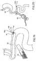
- FIG. 1illustrates a perspective view of a circular stapler
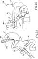
- FIG. 2illustrates a perspective view of a device to be associated with the circular stapler from FIG. 1 ;
- FIG. 2 aillustrates a perspective view of the stapler from FIG. 1 , guide wire and device from FIG. 2 during an assembly step for performing a suture
- FIG. 3illustrates a perspective view of a possible embodiment of a positioning device
- FIG. 4illustrates a sectional view along a plane containing a longitudinal axis of the device from FIG. 3 ;
- FIG. 5illustrates a perspective view of a detail of the device from FIG. 3 ;
- FIG. 6illustrates a perspective view of a detail of the device from FIG. 3 ;
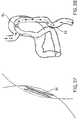
- FIGS. 7 and 8illustrate perspective views of the detail from FIG. 5 from different points of view
- FIG. 9illustrates a perspective view of a possible embodiment of a positioning device
- FIG. 10illustrates a sectional view along a plane containing a longitudinal axis of the device from FIG. 9 ;
- FIG. 11illustrates a partially sectioned, perspective view of a detail of the device from FIG. 9 ;
- FIG. 12illustrates a perspective view of a detail of the device from FIG. 9 ;
- FIG. 13illustrates a perspective view of a possible embodiment of a positioning device
- FIG. 14illustrates a sectional view along a plane containing a longitudinal axis of the device from FIG. 13 ;
- FIG. 15illustrates a perspective view of a detail of the device from FIG. 13 ;
- FIG. 16illustrates a perspective view of a detail of the device from FIG. 13 ;
- FIG. 17-40illustrate several steps of a method according to the present invention.
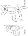
- FIG. 41illustrates a partial perspective view of a circular stapler, a positioning device and a guide wire, an anchoring ring being inserted thereon;
- FIG. 42illustrates the circular stapler, positioning device and guide wire from FIG. 41 while the positioning device is being inserted in the circular stapler;
- FIG. 43illustrates the FIG. 41 in a longitudinal section
- FIG. 44illustrates FIG. 41 from a different point of view.
- a circular stapler portioncomprising a handle 12 and a stem 14 as a whole.
- the structure of the circular stapleris similar to the known circular staplers, which are conventionally used to carry out circular anastomosis, such as of the bowel.
- the structure of the circular stapler according to the present inventionis changed compared with the conventional ones in that, in a preferred embodiment thereof, it has a channel suitable to receive the guide wire.
- the circular stapler 10has a channel crossing the stem 14 thereof from the distal end to an area at the proximal end from which it protrudes outside, for example on one side.
- the guide wireruns all along the length of the circular stapler or only a distal portion thereof.
- the channelis suitable to receive a guide wire (not illustrated in FIG. 1 ) such that the stapler can slide therealong and be placed in the site requiring anastomosis.
- a guide wirenot illustrated in FIG. 1
- An exemplary use of the circular stapler 10will be described below with particular reference to FIG. 29 .
- the length of the stem 14 and the diameter thereofare sufficient to carry out the method and reach the desired site.
- the stemis made of a flexible material, such as to facilitate reaching the site requiring anastomosis.
- the stapler 10advantageously comprises an anvil 16 illustrated for example in FIG. 2 .
- the anvil 16defines an exemplary device for drawing tissues together, particularly a device that, besides drawing the tissues together, is suitable to be associated with the circular anvil 10 such as illustrated in FIG. 1 in order to carry out anastomosis.
- the anvil 16comprises a stem 18 and a head 20 .
- the stem 18has such a longitudinal and cross size that makes it suitable to be fit on the end of the stem 14 of the circular stapler 10 opposite the handle 12 (FIGS. 2 A and 41 - 44 ).
- a channel 22crosses the anvil 16 in a longitudinal direction and is suitable to receive a guide wire, not illustrated in FIG. 2 .
- An exemplary use of the anvil 16 for the circular stapler 10will be described below with particular reference to FIG. 26-29 .
- An anchoring ring suitable to lock the anvil 16 on the guide wire on which it is fitted such as to be drawn by the guide wire in order to draw the tissues together and create the anastomosishas been designated with 76 .
- FIG. 3with 24 has been generally designated a positioning device suitable to draw tissues together which have been subjected to enterostomy, and to place means for providing a passage (anastomosis) between the tissues that have been drawn together.
- the positioning device 24comprises a first component, or proximal component, designated with numeral 26 and a second component, or distal component, designated with reference 28 .
- the positioning device 24extends along a longitudinal axis 30 .
- FIGS. 5 , 7 and 8illustrate perspective views of the proximal component 26
- FIG. 6illustrates a perspective view of the distal component 28 .
- the proximal component 26is suitably shaped to be abutted against the edge of a first enterostomy in order to draw the tissues adjacent thereto against the tissues adjacent to a second enterostomy.
- the distal component 28is suitably shaped to be inserted through the enterostomies.
- the first enterostomywill be also called herein below as the proximal enterostomy, whereas the second enterostomy will be also called the distal enterostomy.
- the first enterostomycan be a gastrostomy and the second enterostomy can be a jejunostomy.
- the first enterostomycan be a proximal jejunostomy and the second enterostomy can be a distal jejunostomy.
- the proximal component 26has a substantially cylindrical outer structure.
- a cavity 32being formed at one of the bases of the cylindrical structure and longitudinally thereto, preferably has a first portion defined by a surface having the shape of a truncated cone 32 a and a second portion defined by a cylindrical surface 32 b .
- the cavity 32does not run through the entire length of the proximal component 26 , leaving a base wall 34 .
- the cross size of the cavity 32 and the proximal component 26are preferably such as to leave an abutment surface, for example a plane annular surface 26 a contouring the cavity.
- a lug 36extends along the longitudinal axis 30 from the bottom of the cavity 32 towards the outside of the cavity, preferably such that a free end 36 a of the lug 36 is completely out of the cavity 32 .
- the length of the lug 36 from the base of cavity 32 to the free end 36 a thereofis preferably greater than the depth of the cavity 32 .
- the lug 36has a preferably cylindrical cavity 38 extending along the longitudinal axis 30 and crossing the base wall 34 leading to the opposite surface of the proximal component 26 .
- the cavity 38involves the lug 36 and base wall 34 thereby generating a duct open at the ends thereof and suitable to receive a guide wire not illustrated in FIG. 3-8 .
- the proximal component 26 comprising the lug 36is made as one piece.
- the proximal component 26comprises holes 40 for example for a suture, which can be used for separating the proximal component from the distal component, to be passed therethrough.
- the distal component 28comprises a head 42 and a stem 44 , which are preferably made as one piece, that develop along the longitudinal axis 30 .
- the head 42preferably has a shape of a truncated cone and, according to a possible embodiment, comprises holes 46 for a suture, which can be used for example to separate the distal component from the proximal component, to be passed therethrough.
- the stem 44preferably has a cylindrical structure and a free end thereof, i.e. opposite the head 42 , widens to form a preferably annular base 48 .
- a channel 50extends along the longitudinal axis 30 from the end of head 42 to the base 48 and is suitable to receive a guide wire therein, not illustrated in FIG. 4 or 6 .
- the cross size of channel 50at least in the portion at the base 48 , are such as to receive the lug 36 of the proximal component 26 therein.
- the channel 50preferably has a larger section at the area in which it receives the lug 36 .
- the remaining part of channel 50has the same cross size as the cavity 38 .
- FIGS. 3 and 4illustrate the positioning device 24 when assembled.
- the proximal component 26 and the distal component 28are joined such that the cavity 38 and channel 50 define a channel running all along the assembly for introducing a guide wire, not illustrated in FIGS. 3 and 4 .
- FIG. 4illustrates the positioning device 24 sectioned along a plane comprising the longitudinal axis 30 .
- the proximal component 26 and the distal component 28lock an elastic ring 52 therebetween, which is hold in a compressed/deformed configuration, and suitable to be placed by the positioning device 24 in a desired anastomotic site in which, after it has been positioned, the elastic ring 52 takes a preset non-compressed rest shape (see for example FIG. 37 ).
- the elastic ringcan be made of Nitinol, stainless steel or other satisfying materials.
- the elastic ring 52 in its deformed configurationhas an end, such as the proximal (designated with numeral 52 a ), that is locked between the base 48 of the distal component 28 and the inner diameter of the cavity 32 of the proximal component 26 , i.e. inside the cylindrical portion 32 b of the cavity 32 .
- the opposite end of the elastic ring 52i.e. the distal end designated with the numeral 52 b , is preferably unfastened and abuts beneath the head 42 of the distal component 28 .
- the cross size of the distal end 52 b of the elastic ring 52does not exceed the cross size of the head 42 of the distal component 28 .
- the outer diameter of the proximal componentis intended to act as a striker against the wall of the tissue to be drawn together, or in other words, abut against the proximal enterostomy while it minimizes the risk of penetration in the wall.
- the distal component 28with its head 42 , is intended to penetrate in the proximal and distal enterostomies and protects the elastic ring 52 while being inserted and positioned, such as will be described in the following.
- FIG. 9-12illustrate a possible variant embodiment of the positioning device 24 and the proximal and distal components thereof according to the present invention.
- the elements in commonhave been designated with the same numeral used in FIG. 3-8 and will be described below with reference to the differences from the above embodiment.
- the proximal component 26is substantially similar to the one illustrated in FIGS. 3-5 , 7 and 8 .
- the stem 44extends straight up to its free end opposite the head 42 that does not widen to form a base similar to the base 48 of the distal component described above.
- the head 42preferably having the shape of a cone or truncated cone, comprises a flange 54 extending from the outer perimeter of the major base of the head to form a circular wall substantially parallel to the longitudinal axis 30 .
- FIGS. 9 and 10illustrate the positioning device 24 when assembled, in which the channel 50 and the cavity 38 define a channel extending along the longitudinal axis 30 through the entire length of the assembled positioning device 24 to receive a guide wire, not illustrated in the FIG. 9-12 .
- the elastic ring 52is hold between the proximal component 26 and the distal component 28 in a compressed/deformed configuration. After the elastic ring has been positioned, it takes a preset, uncompressed rest shape as described above.
- the proximal end 52 a of the elastic ring 52is fastened by the inner diameter of the cavity 32 , particularly by the cylindrical portion 32 b of the cavity 32 , whereas the distal end 52 b of the elastic ring 52 is fastened within the circular flange 54 of the distal component 28 .
- the cross size of channel 50at least in the portion at the base 48 , are such as to receive the lug 36 of the proximal component 26 therein.
- the channel 50has a larger section at the area where it receives the lug 36 .
- the remaining part of channel 50has the same cross size as the cavity 38 .
- the elastic ring 52can be made of Nitinol (Ni—Ti alloy), stainless steel or other satisfying materials.
- the exemplary use of the positioning deviceis similar throughout the various embodiments described.
- FIG. 13-16illustrate a possible variant embodiment of the positioning device and the proximal and distal components thereof according to the present invention.
- the elements in commonhave been designated with the same numeral used in the figures above and will be described below with reference to the differences from the above embodiments.
- the proximal component 26has a prismatic outer structure, preferably having a rectangular base.
- the cavity 32is formed at one of the bases of the structure and does not run through the entire length of the proximal component 26 , leaving a base wall 34 .
- the sizes of the cavity 32 and proximal component 26are such as to leave a peripheral flat surface 26 a.
- a preferably cylindrical cavity 38extending along the longitudinal axis 30 and crossing the entire thickness of the base wall.
- Ribs 56preferably on opposite parts of cavity 38 and parallel to the long sides of the rectangular base, extend from the bottom of the cavity 32 by a height preferably less than the depth of cavity 32 .
- the proximal component 26comprises holes 40 for example for a suture, which can be used for separating the proximal component from the distal component, to be passed therethrough.
- the distal component 28comprises a head 42 , which according to a possible embodiment, comprises holes (not illustrated) for a suture, which can be used for example to separate the distal component from the proximal component, to be passed therethrough.
- the channel 50extends along the longitudinal axis 30 throughout the solid thickness of the head 42 , preferably in the middle thereof, and is suitable to receive a guide wire therein, not illustrated in FIG. 14 or 15 .
- the head 42has a tract having a substantially pyramidal or having a truncated-pyramid shape, preferably with a rectangular base.
- Two flanges 54that preferably involve the short sides of the rectangular base and a limited portion of the long sides extend from the outer periphery of the major base of the truncated-pyramidal portion, in a direction substantially parallel to the longitudinal axis 30 .
- a preferably flat extension 58arranged at a middle portion of each long side of the rectangular base and projecting in the direction substantially parallel to the longitudinal axis 30 along a preferably longer tract than the flanges 54 .
- FIGS. 13 and 14illustrate the positioning device 24 when assembled, in which the channel 50 and the cavity 38 are arranged along the longitudinal axis 30 to receive a guide wire, not illustrated in the FIG. 13-16 .
- the elastic ring 52is hold between the proximal component 26 and the distal component 28 in a preferably flattened, compressed/deformed configuration. After the elastic ring has been positioned, it takes a preset, uncompressed rest shape as described above. In the deformed configuration, the proximal end 52 a of the elastic ring 52 is fastened by the inner periphery of the cavity 32 .
- the ribs 56fasten the elastic ring 52 in a flat deformed configuration, or in other words, the elastic ring 52 is arranged between the wall of the cavity 32 and the ribs 56 . Furthermore, the distal end 52 b of the elastic ring 52 is fastened by the flanges 54 and extensions 58 , when the latter are provided.
- the assembled configuration of the positioning device 24is ensured by the interference between the proximal end 52 a of the elastic ring 52 and the walls of the proximal component 26 defining the cavity 32 , and on the other hand by the interference between the distal end 52 b of the elastic ring 52 and the flanges 54 and the extensions 58 , when the latter are provided.
- the elastic ring 52can be made of Nitinol, stainless steel or other satisfying materials.
- the exemplary use of the positioning deviceis similar throughout the various embodiments described.
- the peripheral wall 26 a of the proximal component 26is the one intended to abut against the wall of the tissue to be drawn together while minimizing the risk that the wall may be penetrated.
- the angled head 42 of the distal component 28is intended to penetrate the proximal and distal enterostomies and protects the elastic ring 52 when being introduced and positioned by fastening the ring within the flanges 54 and the extensions 58 , such as will be described in the following.
- the channel 50 and the cavity 38are intended to house a guide wire for transporting the positioning device.
- the present inventionfurther relates to a method for the therapy of obesity and particularly a method for carrying out anastomosis in tracts of the digestive tube.
- FIG. 17-40illustrate several steps of a possible embodiment of the method according to the present invention. The examples illustrated particularly relate to a method for carrying out an endoluminal/transluminal gastrojejunostomy (G-J) and a jejunojejunostomy (J-J) via transoral access.
- G-Jendoluminal/transluminal gastrojejunostomy
- J-Jjejunojejunostomy
- the method according to the present inventionadvantageously provides to draw tissues together and carry out anastomosis via endoluminal access by introducing, through a natural orifice (such as nose, mouth, ears, anus) or other luminal structures, guide or rail means within the tissues to be drawn together. Suitable components or devices can be thereby carried to the anastomotic site such that the surfaces of the tissues are suitably drawn together and connected with a channel (anastomosis).
- a natural orificesuch as nose, mouth, ears, anus
- Suitable components or devicescan be thereby carried to the anastomotic site such that the surfaces of the tissues are suitably drawn together and connected with a channel (anastomosis).
- the guide or rail meansare introduced such as to generate an open ring that can begin and end in natural orifices, such as the mouth, nose, anus or other natural orifices, such as colostomy, trocar, abdomen incisions, wounds, fistulae.
- natural orificessuch as the mouth, nose, anus or other natural orifices, such as colostomy, trocar, abdomen incisions, wounds, fistulae.
- the components or devices provided to draw the tissues togetherare advantageously moved by locking the device on the guide wire and pulling one of the guide wire ends.
- the ends of the open ring and accordingly of the main guide wireare different from each other, and hence distinguishable.
- the guide wireis internally hollow, i.e. it has a tubular structure suitable to receive needles for perforating the tissues and carrying out proximal and distal enterostomies. Perforation can take place for example either by pushing the needle through the tissues, or applying a radiofrequency through the needle.
- the open ringthen crosses the proximal enterostomy and then the distal enterostomy, for example by using a gripping device.
- the positioning device 24is locked on the guide wire by means of an anchoring ring 76 and drawn by the guide wire until it is partially inserted in the proximal enterostomy and abutted against a first tissue portion to be joined. The positioning device 24 is further drawn until it is partially inserted in a distal enterostomy by drawing together the tissue portions to be joined. Finally, the positioning device 24 partially inserted in the proximal and distal enterostomy releases an elastic ring 52 riding the proximal and distal enterostomies to hold the tissue portions joined to each other thereby generating a passage or anastomosis.
- FIG. 17-29illustrate a gastrojejunostomy (G-J) step that is advantageously carried out by introducing guide or rail means through a natural orifice (such as the nose or mouth). Subsequently, the guide means, a guide wire in this case, form an open ring crossing the points of the tissues to be joined.
- G-Jgastrojejunostomy
- FIG. 17illustrates a first step, which is designated as the step 1 , in which a substantially conventional laparoscope 60 has been introduced in the abdominal cavity to view the areas to be treated.
- This stepcan be potentially eliminated after a certain degree of skill in the method has been achieved, thereby the method can be made completely endoluminal and transluminal.
- the laparoscope 60is illustrated in FIG. 17 and also in the subsequent steps, but it can be omitted as well.
- a gastroscopic controlcan be provided, i.e. by introducing a secondary gastroscope for example through the esophagus or mouth having the function of controlling the method steps.
- a main gastroscope carrying out the method steps and a secondary gastroscope monitoring the operationwill be introduced.
- FIG. 18illustrates a step of the method according to the present invention, which is also designated as the step 2 , in which a substantially conventional main gastroscope 62 is introduced through the esophagus, stomach, passing through the pylorus and subsequently the duodenum to reach the jejunum.
- a substantially conventional main gastroscope 62is introduced through the esophagus, stomach, passing through the pylorus and subsequently the duodenum to reach the jejunum.
- the gastroscope 62is advanced by approximatively 20-40 cm beyond the pylorus.
- FIG. 19illustrates a detail of the jejunum and the end of the gastroscope 62 .
- the latterconventionally comprises several channels 64 crossing the entire length thereof and that can be used for tools or the like to be passed therethrough.
- the step from FIG. 19also designated as the step 3 , provides that a first guide wire 66 or main guide wire being suitable to provide the open ring is advanced along one of the channels 64 of the gastroscope 62 .
- the guide wireis advanced until a pointed end 66 a thereof or a needle sliding along the tubular structure of the guide wire protrudes from the gastroscope.
- the end 66 a of the guide wire 66perforates the jejunum wall from the inside and creates a jejunostomy (proximal enterostomy).
- the laparoscope 60is optionally provided. When this is provided, the guide wire 66 is advanced and the jejunostomy is created under the laparoscope visual control.
- the jejunostomycan be carried out by pushing the guide wire directly through the jejunum wall.
- radiofrequency energymay be applied to perforate the jejunum wall and then advance the guide wire 66 .
- a first guide wire 66being part of guide or rail means which will be subsequently indicated in greater detail, is positioned within the tissue to be joined and passed through one of the tissue portions to be joined.
- the jejunum tissue portion to be drawn near and joined to the stomach thereby forming an anastomosishas been designated with A.
- FIG. 20illustrates a step which has been designated as the step 4 in which the gastroscope 62 is removed and the guide wire 66 is left in the abdomen within the stomach and along a jejunum tract with the end 66 a protruding from the jejunum at the tissue portion A to be joined.
- the step 4can be carried out under laparoscopic control (laparoscope 60 ), when provided.
- FIG. 21illustrates a step which is designated as the step 5 , in which a main gastroscope 62 , of a substantially conventional type, has been introduced again in the stomach through the esophagus, in order to create a gastrostomy (distal enterostomy). Also in this case, one may directly push either a secondary guide wire 77 with a pointed end 77 a or a needle sliding within the tubular structure of the guide wire. Alternatively, or in addition thereto, radiofrequency energy can be applied in order to perforate the stomach wall and advance the guide wire.
- the gastrostomyis carried out in a stomach portion corresponding to the area to be joined. This portion has been designated with A′.
- Step 5may also be carried out under laparoscopic control.
- FIG. 22illustrates a step of the method according to the present invention, which has been designated as the step 6 , in which the gastrostomy is enlarged by means of a balloon catheter 72 .
- the catheteris inserted in the gastroscope 62 until a balloon-end 72 a thereof reaches the gastrostomy which is enlarged by inflating the balloon.
- Step 6may also be carried out under laparoscopic control.
- FIG. 23illustrates a step of the method according to the present invention, which has been also designated as the step 7 , in which the gastroscope 62 is advanced through the gastrostomy enlarged by the balloon, within the abdominal cavity.
- Step 7can be carried out either under gastroscopic (secondary gastroscope) and/or laparoscopic (laparoscope 60 ) control.
- gastroscopic controlis meant a control carried out by means of a secondary gastroscope, not illustrated in FIG. 23 , which is introduced through the esophagus having only a control function.
- This secondary gastroscopecan be provided in every step whenever a gastroscopic control as an alternative or in addition to the laparoscopic control is required.
- FIG. 24illustrates a step which has been designated as the step 8 , in which a gripping device 74 (forceps or the like) is advanced through the gastroscope 62 and the end 66 a of the guide wire 66 protruding from the jejunostomy is coupled therethrough. Gripping the guide wire point is not required.
- a gripping device 74forceps or the like
- the gripping device 74can be for example a loop-shaped endoscopic instrument for polypectomies.
- FIG. 25illustrates a step which has been designated as the step 29 , in which the guide wire 66 of the jejunum is pulled through the gastrostomy in order to provide a first ring 80 open at the ends thereof, or gastro-jejunum ring (ring 1 ), the ends thereof protruding from the orifice used (the mouth, esophagus, . . . ).
- the end of ring 80 corresponding to the jejunum (jejunum end), i.e. the end passing through the stomach and jejunum and protruding from portion Ahas been designated with 80 a
- the end of the ring 80 corresponding to the stomach (stomach end)i.e. the end passing through the stomach and protruding therefrom at portion A′ has been designated with 80 b . Both ends are advantageously different from each other in order to be distinguished.
- the ring 80can be now used as a guide means or rail system in order to introduce and carry suitable anastomotic devices suitable to draw the tissues together and carry out the anastomosis in the site of interest.
- the anastomotic devicesare advantageously locked on the guide wire for example by means of an anchoring ring 76 and one of the ends of the ring is pulled until the anastomotic device partially enters the proximal enterostomy, draws the tissues thereof near the distal enterostomy and partially enters the same.
- FIG. 26illustrates a step which has been designated as the step 10 , wherein the selected anastomotic device (anvil 16 , positioning device 24 , etc.) is inserted on the guide wire from the jejunum end 80 a and pulled along the ring 80 of guide wire through the esophagus, stomach, duodenum and jejunum. Drawing is allowed by an anchoring ring 76 which is made integral with the guide wire such as to push against the proximal part of the selected anastomotic device.
- the selected anastomotic deviceanvil 16 , positioning device 24 , etc.
- FIG. 26Although an anvil 16 has been illustrated in FIG. 26 , a positioning device 24 or other similar devices can be used as well.
- the anastomotic deviceBy pulling the guide wire from the end of stomach 80 b , the anastomotic device can be pulled until the portion A of the jejunum (proximal enterostomy).
- the end of the jejunum part of the guide wire 80 ais inserted in the channel 22 of the anvil 16 from the side of the stem 18 .
- the end of the jejunum part of the guide wire 80 awould be inserted in the channel 50 from the side of the distal component 28 .
- FIG. 27illustrates a step which has been also designated as the step 11 , in which the anastomotic device and particularly the anvil 16 is pulled until it has partially passed the jejunostomy (proximal enterostomy).
- jejunostomyproximal enterostomy
- FIG. 28illustrates a step which has been also designated as the step 12 , in which by keeping on pulling the end of the guide wire 80 b from the side of the stomach, the anvil 16 and particularly the head 20 acts as a striker against the inner wall of the portion A of the jejunum and draws the jejunum until the portion A is drawn near the stomach and particularly portion A′.
- the stem 18 of the anvil 16also partially enters the gastrostomy (distal enterostomy).
- the operationcan be carried out under laparoscopic control (laparoscope 60 ).
- laparoscope 60When a positioning device 24 is used, the head would 42 enter the gastrostomy whereas the flat peripheral surface 26 a would draw the relative contouring tissues together.
- FIG. 29illustrates a step which has been indicated as the step 13 , in which the traction on the stomach end 80 b of the guide wire is maintained in order to maintain the portions A and A′ near each other. Furthermore, a circular stapler 10 is caused to slide on the guide wire from the stomach end 80 b until it reaches the inside of the stomach, and until the stem 18 of the anvil 16 connects to the end of the stem 14 of the stapler 10 (such as illustrated in greater detail in FIGS. 2 a and 41 - 44 ). The stapler 10 carries out the anastomosis between the portion A and the portion A′ by cutting and suturing the tissue in a circular manner. A passage 84 is thereby formed ( FIG. 30 ) which directly communicates the stomach and jejunum. When a positioning device 24 is used, the passage 84 is obtained by detaching the proximal component from the distal component and releasing the elastic ring 52 riding both enterostomies.
- the guide wire 66is removed by drawing one end thereof.
- FIG. 30-40illustrate a jejunojejunostomy (J-J) step that is advantageously carried out by introducing guide or rail means through a natural orifice (such as the esophagus or mouth). Subsequently, the guide means, a guide wire in this case, form an open ring crossing the points of the tissues to be joined.
- J-Jjejunojejunostomy
- FIG. 30illustrates a step designated as the step 14 , in which a substantially conventional gastroscope 62 is introduced through the esophagus, stomach, passing through the pylorus and subsequently the duodenum to reach the jejunum.
- the gastroscope 62is advanced to a portion to be joined that is designated with B in order to carry out a proximal jejunostomy, which portion is proximally arranged relative to channel 84 (anastomosis) that has already been created.
- a guide wire 86or main guide wire, intended to form the open ring is advanced along a channel 64 .
- the guide wireis advanced until a pointed end 86 a thereof or a needle sliding within the guide wire protrudes from the gastroscope.
- the end 86 a of the guide wire 66perforates the jejunum wall from the inside and creates a jejunostomy (proximal enterostomy).
- the laparoscope 60is optionally provided. When this is provided, the guide wire 86 is advanced and the jejunostomy is created under the laparoscope visual control.
- the jejunostomycan be carried out by pushing the guide wire directly through the jejunum wall.
- radiofrequency energymay be applied to perforate the jejunum wall and then advance the guide wire 86 .
- a guide wire 86being part of guide or rail means which will be subsequently indicated in greater detail, is positioned within the tissue to be joined and passed through one of the tissue portions B to be joined (proximal jejunostomy).
- FIG. 31illustrates a step which has been indicated as the step 15 , in which the gastroscope 62 is removed and the guide wire 86 is left within the stomach and jejunum, with the end 86 a protruding from the walls of the jejunum (proximal jejunostomy).
- the gastroscope 62is then advanced through the stomach, the previously accomplished gastrojejunostomy (step 84 ) and a tract of the distal jejunum until a sufficient distance to create the jejunumjejunum (J-J) anastomosis.
- the latter portionhas been indicated with the reference B′. Analogously to FIGS.
- a secondary guide wireis advanced along the gastroscope 62 until a pointed end thereof protrudes from the end of the gastroscope 62 .
- This pointed endis then passed through the tissue walls at the portion B′ in order to create a distal jejunostomy.
- the distal jejunostomycan be also carried out either by directly pushing the pointed end through the jejunum wall or applying radiofrequency energy in order to perforate the wall, subsequently advancing the guide wire.
- the creation of the distal jejunostomycan be monitored through the laparoscope.
- a catheter with balloon-endmay be optionally inserted along the gastroscope.
- the balloon endWhen the balloon end is near the distal jejunostomy, the balloon is inflated in order to dilate the distal jejunostomy and the gastroscope is pushed in the abdominal cavity. This dilation may be required when the laparoscope is not used and monitoring is carried out through the gastroscope such that the latter can view the end 86 a of the guide wire 86 .
- FIG. 32illustrates a step which has been designated as the step 16 , in which a gripping device 74 (endoscopic forceps or the like) similar to the one used in step 8 , is advanced through the gastroscope to lock the end 86 a of the main guide wire 86 protruding from the proximal jejunostomy site. Gripping the guide wire end is not required.
- a gripping device 74endoscopic forceps or the like
- FIG. 33illustrates a step which has been indicated as the step 17 , in which the gastroscope has been removed and the main guide wire 86 has been pulled through the distal jejunostomy to form a ring 88 open at the ends thereof, or jejunumjejunum ring (the ring 2 ), the ends thereof protruding from the orifice used.
- the end of the jejunumi.e. the end passing through the stomach and the jejunum and protruding therefrom at portion B
- the end of the stomachi.e. the end passing through the stomach, protruding from the gastrojejunostomy (passage 84 ) and protruding from the jejunum at portion B′ has been designated with 88 b.
- the ring 88can be now used as a guide means or rail system in order to introduce and carry suitable anastomotic devices suitable to draw the tissues together and carry out the anastomosis in the site of interest (J-J). As described above, the anastomotic device is locked on the guide wire, an end thereof being pulled in order to advance the anastomotic device.
- FIG. 34illustrates a step which has been designated as the step 18 , wherein an anastomotic device such as a positioning device 24 is inserted from the jejunum end 88 a and pulled along the ring 88 of guide wire through the esophagus, stomach, duodenum and jejunum.
- the operationmay be carried out under laparoscopic and/or gastroscopic control in order to view the movement.
- the anastomotic devicemay be caused to slide on the guide wire from the jejunum end 88 a . Traction is permitted due to an anchoring ring similar to that described above, which is made integral with the guide wire pushing against the proximal part of the selected anastomotic device. By pulling the guide wire from the end of stomach 88 b , the anastomotic device can be pulled until the portion B of the jejunum.
- the positioning device 24(channel 50 and cavity 38 ) is inserted on the end 88 a of the guide wire from the side of the distal component 28 .
- the anastomotic device and particularly the positioning device 24is pulled until it has partially passed the proximal jejunostomy.
- the head 42 of the distal component 28 and a part of the elastic ring 52cross the proximal jejunostomy and protrude in the abdominal cavity, whereas the other part of the elastic ring 52 remains within the jejunum.
- the proximal componentalso remains within the jejunum and abuts, for example with the surface 26 a , against the tissue wall to act as a striker.
- FIG. 35illustrates a step which has been designated as the step 19 , in which the two jejunum branches are drawn together, optionally under gastroscopic and/or laparoscopic vision by keeping on pulling the anastomotic device (positioning device 24 ).
- the head 42 of the distal component 28 with a part of the elastic ring 52penetrate in the distal jejunostomy.
- FIG. 36illustrates a step which has been designated as the step 20 , in which the elastic ring 52 that takes its uncompressed configuration, such as illustrated enlarged for example in FIG. 37 (step 21 ) is positioned.
- the ends of the elastic ring 52fold between the proximal jejunostomy and the distal jejunostomy thereby maintaining the portion B and portion B′ joined to each other thereby creating a circular anastomosis.
- the elastic ring 52can be released from the positioning device 24 by simultaneously uncoupling the distal and proximal components 26 and 28 . Alternatively, one of the two components can be uncoupled by pulling the same while keeping unchanged the position of the elastic ring 52 relative to the anastomotic site.
- the suture threads protruding from the holes 40 of the proximal component 26 and the holes 46 of the distal component 28by coupling them by means of a suitable tool inserted in a gastroscope 62 .
- the suture stitchesare thus gripping points for uncoupling the proximal and distal components of the positioning device 24 from each other.
- the enterostomycan be viewed by means of a gastroscope or laparoscope.
- the guide wire 86is removed by drawing one end thereof.
- FIG. 38illustrates a step which has been designated as the step 22 , in which the gastrojejunostomy (G-J) and the jejunojejunostomy (J-J) have been completed and in which there is illustrated the route followed by the food along the digestive tract after it has been changed.
- G-Jgastrojejunostomy
- J-Jjejunojejunostomy
- a gastric partition obtained with a gastric bandage such as illustrated in FIG. 39(step 23 . 1 ) or a gastric partition obtained with an endoscopic stapler such as illustrated in FIG. 40 (step 23 . 2 ) can be provided.
- guide means carrying components or devices to the desired anastomotic site through natural orificessuch as the nose, mouth, ear, anus
- guide meanscarrying components or devices to the desired anastomotic site through natural orifices (such as the nose, mouth, ear, anus) or other luminal structures in order to carry out anastomosis greatly simplifies the procedure, shortens the patient's convalescence and eliminates the drawbacks of traditional surgery.
- the gastrojejunostomy G-Jaccording to the steps described above ( FIG. 17-FIG . 29 ) can be carried out by means of a positioning device 24 as described above (similarly to the jejunojejunostomy J-J steps corresponding to FIG. 31-38 ).
Landscapes
- Health & Medical Sciences (AREA)
- Life Sciences & Earth Sciences (AREA)
- Surgery (AREA)
- Heart & Thoracic Surgery (AREA)
- Engineering & Computer Science (AREA)
- Biomedical Technology (AREA)
- Nuclear Medicine, Radiotherapy & Molecular Imaging (AREA)
- Medical Informatics (AREA)
- Molecular Biology (AREA)
- Animal Behavior & Ethology (AREA)
- General Health & Medical Sciences (AREA)
- Public Health (AREA)
- Veterinary Medicine (AREA)
- Physiology (AREA)
- Surgical Instruments (AREA)
Abstract
Description
Claims (6)
Applications Claiming Priority (3)
| Application Number | Priority Date | Filing Date | Title |
|---|---|---|---|
| IT002132AITMI20042132A1 (en) | 2004-11-05 | 2004-11-05 | DEVICE AND METHOD FOR OBESITY THERAPY |
| ITMI2004A002132 | 2004-11-05 | ||
| PCT/IT2005/000348WO2006048905A1 (en) | 2004-11-05 | 2005-06-17 | A device and method for the therapy of obesity |
Publications (2)
| Publication Number | Publication Date |
|---|---|
| US20080302855A1 US20080302855A1 (en) | 2008-12-11 |
| US8006701B2true US8006701B2 (en) | 2011-08-30 |
Family
ID=34979462
Family Applications (1)
| Application Number | Title | Priority Date | Filing Date |
|---|---|---|---|
| US11/662,029Expired - Fee RelatedUS8006701B2 (en) | 2004-11-05 | 2005-06-17 | Device and method for the therapy of obesity |
Country Status (10)
| Country | Link |
|---|---|
| US (1) | US8006701B2 (en) |
| EP (1) | EP1809182B1 (en) |
| JP (1) | JP5037353B2 (en) |
| CN (1) | CN100522079C (en) |
| AU (1) | AU2005302041B2 (en) |
| BR (1) | BRPI0517049B8 (en) |
| CA (1) | CA2587954C (en) |
| IT (1) | ITMI20042132A1 (en) |
| MX (1) | MX2007005485A (en) |
| WO (1) | WO2006048905A1 (en) |
Cited By (159)
| Publication number | Priority date | Publication date | Assignee | Title |
|---|---|---|---|---|
| US20090082777A1 (en)* | 2007-09-24 | 2009-03-26 | Milliman Keith L | Insertion Aid with Interference Fit |
| US8146790B2 (en) | 2009-07-11 | 2012-04-03 | Tyco Healthcare Group Lp | Surgical instrument with safety mechanism |
| US8281974B2 (en) | 2009-01-14 | 2012-10-09 | Tyco Healthcare, Group LP | Surgical stapler with suture locator |
| US8424535B2 (en) | 2008-11-06 | 2013-04-23 | Covidien Lp | Circular surgical stapler with mating anvil and shell assembly |
| US8708212B2 (en) | 2011-10-18 | 2014-04-29 | Covidien Lp | Tilt top anvil with torsion spring |
| US9010605B2 (en) | 2012-01-12 | 2015-04-21 | Covidien Lp | Sliding sleeve for circular stapling instrument reloads |
| US9016547B2 (en) | 2011-10-26 | 2015-04-28 | Covidien Lp | EEA tilt top anvil with ratchet/locking mechanism |
| US9022274B2 (en) | 2012-02-15 | 2015-05-05 | Covidien Lp | Circular stapler with increased lumen diameter |
| US9351734B2 (en) | 2012-06-19 | 2016-05-31 | Covidien Lp | Spring loaded anvil retainer |
| US9351724B2 (en) | 2013-01-11 | 2016-05-31 | Covidien Lp | Circular stapling instrument |
| US9463018B2 (en) | 2009-02-06 | 2016-10-11 | Covidien Lp | Anvil for surgical stapler |
| US9517070B2 (en) | 2013-11-13 | 2016-12-13 | Covidien Lp | Anvil assembly and delivery system |
| US9526648B2 (en) | 2010-06-13 | 2016-12-27 | Synerz Medical, Inc. | Intragastric device for treating obesity |
| US9532780B2 (en) | 2013-06-12 | 2017-01-03 | Covidien Lp | EEA anvil snap ring activator |
| US9554802B2 (en) | 2013-11-13 | 2017-01-31 | Covidien Lp | Anvil assembly with frangible retaining member |
| US9572572B2 (en) | 2012-11-09 | 2017-02-21 | Covidien Lp | Circular stapler mechanical lockout |
| US9579099B2 (en) | 2014-01-07 | 2017-02-28 | Covidien Lp | Shipping member for loading unit |
| US9592056B2 (en) | 2013-03-14 | 2017-03-14 | Covidien Lp | Powered stapling apparatus |
| US9668740B2 (en) | 2013-06-14 | 2017-06-06 | Covidien Lp | Anvil assembly with sliding sleeve |
| US9675359B2 (en) | 2012-10-10 | 2017-06-13 | Covidien Lp | Surgical instrument with preload assembly |
| US9693773B2 (en) | 2013-09-11 | 2017-07-04 | Covidien Lp | Anvil assembly with sliding sleeve |
| US9730694B2 (en)* | 2014-07-01 | 2017-08-15 | Covidien Lp | Loading unit including shipping assembly |
| US9750503B2 (en) | 2013-07-11 | 2017-09-05 | Covidien Lp | Methods and devices for performing a surgical anastomosis |
| US9757133B2 (en) | 2014-07-09 | 2017-09-12 | Covidien Lp | Methods and devices for performing a surgical anastomosis |
| US9855045B2 (en) | 2014-12-09 | 2018-01-02 | Covidien Lp | Anvil assembly delivery system |
| US9861367B2 (en) | 2014-06-24 | 2018-01-09 | Covidien Lp | Anvil assembly delivery systems |
| US9867619B2 (en) | 2014-06-24 | 2018-01-16 | Covidien Lp | System for delivering an anvil assembly to a surgical site |
| US9913643B2 (en) | 2014-05-09 | 2018-03-13 | Covidien Lp | Interlock assemblies for replaceable loading unit |
| US9974536B2 (en) | 2015-07-02 | 2018-05-22 | Covidien Lp | Anvil assemblies and delivery systems |
| US9980730B2 (en) | 2015-09-21 | 2018-05-29 | Covidien Lp | Loading unit locking collar with rotational actuated release |
| US9987001B2 (en) | 2015-06-12 | 2018-06-05 | Covidien Lp | Surgical anastomosis apparatus |
| US10010439B2 (en) | 2010-06-13 | 2018-07-03 | Synerz Medical, Inc. | Intragastric device for treating obesity |
| US10022126B2 (en) | 2015-01-07 | 2018-07-17 | Covidien Lp | Loading unit locking collar |
| US10039546B2 (en) | 2013-12-23 | 2018-08-07 | Covidien Lp | Loading unit including shipping member |
| US10039549B2 (en) | 2015-01-07 | 2018-08-07 | Covidien Lp | Loading unit retention clip for surgical stapling instrument |
| US10085756B2 (en) | 2015-07-24 | 2018-10-02 | Covidien Lp | Anvil assembly and anvil assembly delivery system |
| US10085744B2 (en) | 2014-12-08 | 2018-10-02 | Covidien Lp | Loading unit attachment band for surgical stapling instrument |
| US10111684B2 (en) | 2015-09-25 | 2018-10-30 | Covidien Lp | Adapter assembly including a removable trocar assembly |
| US10111668B2 (en) | 2015-07-02 | 2018-10-30 | Covidien Lp | Anvil assembly with snap backup ring |
| US10117675B2 (en) | 2015-07-28 | 2018-11-06 | Covidien Lp | Trocar tip protector |
| US10117655B2 (en) | 2015-07-22 | 2018-11-06 | Covidien Lp | Loading unit locking band for surgical stapling instrument |
| US10117656B2 (en) | 2015-01-07 | 2018-11-06 | Covidien Lp | Loading unit locking collar |
| US10178994B2 (en) | 2013-03-15 | 2019-01-15 | Covidien Lp | Surgical stapling apparatus with reusable components |
| US10213205B2 (en) | 2012-07-06 | 2019-02-26 | Covidien Lp | T-slot tilt anvil for circular stapling instrument |
| US10271843B2 (en) | 2013-06-17 | 2019-04-30 | Covidien Lp | Surgical instrument with lockout mechanism |
| US10342534B2 (en) | 2017-03-23 | 2019-07-09 | Covidien Lp | Surgical stapling device with releasable knife carrier |
| US10390835B2 (en) | 2015-12-10 | 2019-08-27 | Covidien Lp | Surgical fastener apparatus with linear position sensor |
| US10398439B2 (en) | 2016-02-10 | 2019-09-03 | Covidien Lp | Adapter, extension, and connector assemblies for surgical devices |
| US10405864B2 (en) | 2014-07-04 | 2019-09-10 | Covidien Lp | Loading unit with shipping member for surgical stapling device |
| US10413436B2 (en) | 2010-06-13 | 2019-09-17 | W. L. Gore & Associates, Inc. | Intragastric device for treating obesity |
| US10420665B2 (en) | 2010-06-13 | 2019-09-24 | W. L. Gore & Associates, Inc. | Intragastric device for treating obesity |
| US10426480B2 (en) | 2015-04-29 | 2019-10-01 | Covidien Lp | Cutting ring assembly with rigid cutting member |
| US10426470B2 (en) | 2016-11-04 | 2019-10-01 | Covidien Lp | Stapling device with releasable knife carrier |
| US10499916B2 (en) | 2014-12-11 | 2019-12-10 | Covidien Lp | Surgical stapling loading unit |
| US10499922B2 (en) | 2016-11-04 | 2019-12-10 | Covidien Lp | Stapling device with self-releasing knife carrier pusher |
| US10507022B2 (en) | 2014-06-12 | 2019-12-17 | Covidien Lp | Surgical stapling apparatus |
| US10512466B2 (en) | 2015-11-05 | 2019-12-24 | Covidien Lp | Adapter assembly for surgical device |
| US10517601B2 (en) | 2015-02-15 | 2019-12-31 | Covidien Lp | Surgical stapling device with firing indicator of unitary construction |
| US10524797B2 (en) | 2016-01-13 | 2020-01-07 | Covidien Lp | Adapter assembly including a removable trocar assembly |
| US10542992B2 (en) | 2015-10-19 | 2020-01-28 | Covidien Lp | Loading unit with stretchable bushing |
| US10542985B2 (en) | 2014-12-17 | 2020-01-28 | Covidien Lp | Surgical stapling device with firing indicator |
| US10542993B2 (en) | 2017-02-24 | 2020-01-28 | Covidien Lp | Anvil assembly of circular stapling device including alignment splines |
| US10595871B2 (en) | 2016-05-10 | 2020-03-24 | Covidien Lp | Insertion instrument, adapter assemblies and protector assemblies for a flexible circular stapler |
| US10603042B2 (en) | 2016-02-10 | 2020-03-31 | Covidien Lp | Flexible circular stapler |
| US10695069B2 (en) | 2017-08-23 | 2020-06-30 | Covidien Lp | Circular stapling device with offset spline tip |
| US10772627B2 (en) | 2014-12-11 | 2020-09-15 | Covidien Lp | Stapler with auto-matic lockout mechanism |
| US10779980B2 (en) | 2016-04-27 | 2020-09-22 | Synerz Medical, Inc. | Intragastric device for treating obesity |
| US10828026B2 (en) | 2017-08-08 | 2020-11-10 | Covidien Lp | Tiltable anvil assembly |
| US10842495B2 (en) | 2015-10-21 | 2020-11-24 | Covidien Lp | Annular knife for a surgical stapler |
| US10874399B2 (en) | 2016-02-04 | 2020-12-29 | Covidien Lp | Circular stapler with visual indicator mechanism |
| US10881408B2 (en) | 2015-04-22 | 2021-01-05 | Covidien Lp | Interlock assembly for replaceable loading units |
| US10881409B2 (en) | 2017-05-02 | 2021-01-05 | Covidien Lp | Rotation assembly for a surgical device |
| US10932783B2 (en) | 2015-11-13 | 2021-03-02 | Covidien Lp | Circular stapler with audible indicator mechanism |
| US10932784B2 (en) | 2017-06-09 | 2021-03-02 | Covidien Lp | Handheld electromechanical surgical system |
| US10952734B2 (en) | 2018-04-23 | 2021-03-23 | Covidien Lp | Stapling device with cut ring biasing member |
| US10973522B2 (en) | 2015-10-20 | 2021-04-13 | Covidien Lp | Circular stapler with tissue gap indicator assembly |
| US10973544B2 (en) | 2018-10-02 | 2021-04-13 | Covidien Lp | Retaining mechanism for trocar assembly |
| US10987107B2 (en) | 2017-07-05 | 2021-04-27 | Covidien Lp | Surgical stapling device |
| US11020119B2 (en) | 2015-12-07 | 2021-06-01 | Covidien Lp | Anvil assembly and delivery system |
| US11045199B2 (en) | 2017-06-09 | 2021-06-29 | Covidien Lp | Handheld electromechanical surgical system |
| US11065005B2 (en) | 2018-11-07 | 2021-07-20 | Covidien Lp | Reload assembly for a circular stapling device |
| US11071549B2 (en) | 2017-03-23 | 2021-07-27 | Covidien Lp | Circular stapling device with alignment splines |
| US11090054B2 (en) | 2017-08-07 | 2021-08-17 | Covidien Lp | Stapling device with resettable tilt anvil assembly |
| US11116507B2 (en) | 2017-03-09 | 2021-09-14 | Covidien Lp | End effector assembly for a circular stapler apparatus |
| US11123101B2 (en) | 2019-07-05 | 2021-09-21 | Covidien Lp | Retaining mechanisms for trocar assemblies |
| US11141163B2 (en) | 2018-10-04 | 2021-10-12 | Covidien Lp | Circular stapling device with anvil rotation locking structure |
| US11141162B2 (en) | 2016-07-08 | 2021-10-12 | Covidien Lp | Loading unit locking collar with linearly actuated release |
| US11147561B2 (en) | 2018-11-28 | 2021-10-19 | Covidien Lp | Reload assembly for a circular stapling device |
| US11166728B2 (en) | 2019-02-08 | 2021-11-09 | Covidien Lp | Reload assembly for a circular stapling device |
| US11192227B2 (en) | 2019-07-16 | 2021-12-07 | Covidien Lp | Reload assembly for circular stapling devices |
| US11197676B2 (en) | 2018-06-28 | 2021-12-14 | Covidien Lp | Tie-down method for anvil assembly delivery system |
| US11234703B2 (en) | 2017-09-01 | 2022-02-01 | Covidien Lp | Circular stapling device with position ribs |
| US11241232B2 (en) | 2017-01-24 | 2022-02-08 | Covidien Lp | Surgical stapling device with resettable anvil assembly |
| US11241234B2 (en) | 2018-08-14 | 2022-02-08 | Covidien Lp | Anvil assembly with self-retaining backup member |
| US11246599B2 (en) | 2019-04-25 | 2022-02-15 | Covidien Lp | End effector for circular stapling instrument |
| US11253255B2 (en) | 2019-07-26 | 2022-02-22 | Covidien Lp | Knife lockout wedge |
| US11272998B2 (en) | 2020-03-04 | 2022-03-15 | Covidien Lp | Strain gage fixation in tension |
| US11298152B2 (en) | 2020-02-28 | 2022-04-12 | Covidien Lp | Trocar retaining mechanism including band support |
| US11317945B2 (en) | 2019-04-16 | 2022-05-03 | Covidien Lp | Trocar assemblies for adapter assemblies for surgical stapling instruments |
| US11324507B2 (en) | 2017-11-03 | 2022-05-10 | Covidien Lp | Device and method for attachment of a stomal sleeve |
| US11331782B2 (en) | 2019-03-01 | 2022-05-17 | Covidien Lp | Reload assembly for a circular stapling device |
| US11337701B2 (en) | 2019-03-01 | 2022-05-24 | Covidien Lp | Devices and methods for assembling adapter assemblies |
| US11344330B2 (en) | 2019-04-16 | 2022-05-31 | Covidien Lp | Trocar assemblies for adapter assemblies for surgical stapling instruments |
| US11350939B2 (en) | 2020-03-24 | 2022-06-07 | Covidien Lp | Retaining mechanisms for trocar assemblies |
| US11357509B2 (en) | 2019-07-11 | 2022-06-14 | Covidien Lp | Reload assembly for a circular stapling device |
| US11382629B2 (en) | 2017-03-09 | 2022-07-12 | Covidien Lp | Surgical stapling device with audible indicator mechanism |
| US11382630B2 (en) | 2020-02-25 | 2022-07-12 | Covidien Lp | Surgical stapling device with two part knife assembly |
| US11389263B2 (en) | 2018-12-13 | 2022-07-19 | Covidien Lp | Lockout mechanisms for surgical instruments |
| US11399825B2 (en) | 2019-10-28 | 2022-08-02 | Covidien Lp | Reload assembly with knife carrier lockout |
| US11399838B2 (en) | 2019-04-22 | 2022-08-02 | Covidien Lp | Reload assembly for circular stapling devices |
| US11419631B2 (en) | 2019-04-16 | 2022-08-23 | Covidien Lp | Trocar assemblies for adapter assemblies for surgical stapling instruments |
| US11426169B2 (en) | 2020-03-24 | 2022-08-30 | Covidien Lp | Retaining mechanisms for trocar assemblies |
| US11426170B2 (en) | 2020-03-24 | 2022-08-30 | Covidien Lp | Retaining mechanisms for trocar assemblies |
| US11446035B2 (en) | 2019-06-24 | 2022-09-20 | Covidien Lp | Retaining mechanisms for trocar assemblies |
| US11452522B2 (en) | 2016-08-15 | 2022-09-27 | Covidien Lp | Circular stapling device with articulating anvil retainer assembly |
| US11457921B2 (en) | 2019-03-26 | 2022-10-04 | Covidien Lp | Anvil assembly for surgical stapling instrument |
| US11464510B2 (en) | 2019-07-26 | 2022-10-11 | Covidien Lp | Reload assembly with knife carrier lockout |
| US11490894B1 (en) | 2021-05-12 | 2022-11-08 | Covidien Lp | Surgical device with grease filter |
| US11497501B2 (en) | 2018-03-26 | 2022-11-15 | Covidien Lp | Circular stapling device with A-frame splines |
| US11517317B2 (en) | 2020-01-06 | 2022-12-06 | Covidien Lp | Trocar release assemblies for a surgical stapler |
| US11523828B2 (en) | 2020-01-28 | 2022-12-13 | Covidien Lp | Sealed reload assembly for stapling device |
| US11529144B2 (en) | 2019-02-22 | 2022-12-20 | Covidien Lp | Encapsulated plug assembly for electromechanical surgical devices |
| US11534164B2 (en) | 2019-04-05 | 2022-12-27 | Covidien Lp | Strain gauge stabilization in a surgical device |
| US11547412B2 (en) | 2020-07-22 | 2023-01-10 | Covidien Lp | Surgical instruments and methods of assembly |
| US11547438B2 (en) | 2020-02-24 | 2023-01-10 | Covidien Lp | Tip protector for ensuring trocar insertion |
| US11547405B2 (en) | 2020-05-22 | 2023-01-10 | Covidien Lp | Surgical stapling device |
| US11547411B2 (en) | 2019-02-22 | 2023-01-10 | Covidien Lp | Anastomosis wound protector |
| US11553921B2 (en) | 2020-07-15 | 2023-01-17 | Covidien Lp | Surgical stapling device with flexible shaft |
| US11553918B2 (en) | 2019-12-16 | 2023-01-17 | Covidien Lp | Reload assembly with knife carrier lockout |
| US11553920B2 (en) | 2021-05-03 | 2023-01-17 | Covidien Lp | Trocar retainer assembly for surgical stapler |
| US11596400B2 (en) | 2017-06-09 | 2023-03-07 | Covidien Lp | Handheld electromechanical surgical system |
| US11596410B2 (en) | 2019-04-05 | 2023-03-07 | Covidien Lp | Surgical stapling device |
| US11622767B2 (en) | 2020-02-19 | 2023-04-11 | Covidien Lp | Sealed trocar assembly for stapling device |
| US11627966B2 (en) | 2020-08-26 | 2023-04-18 | Covidien Lp | Surgical stapling device |
| US11627967B2 (en) | 2020-11-23 | 2023-04-18 | Covidien Lp | Trans-anastomotic insertion device |
| US11642131B2 (en) | 2021-05-17 | 2023-05-09 | Covidien Lp | Devices and methods for shortening a rectal stump during a lower anterior resection procedure |
| US11653925B2 (en) | 2020-05-21 | 2023-05-23 | Covidien Lp | Tissue relaxation monitoring for optimized tissue stapling |
| US11660116B2 (en) | 2019-04-16 | 2023-05-30 | Covidien Lp | Trocar assemblies for adapter assemblies for surgical stapling instruments |
| US11678885B2 (en) | 2017-01-25 | 2023-06-20 | Covidien Lp | Circular stapling device and method of use |
| US11690624B2 (en) | 2019-06-21 | 2023-07-04 | Covidien Lp | Reload assembly injection molded strain gauge |
| US11712509B2 (en) | 2020-10-02 | 2023-08-01 | Covidien Lp | Seal assembly for circular stapling instrument |
| US11717299B2 (en) | 2021-10-12 | 2023-08-08 | Covidien Lp | Surgical stapling device with probiotics |
| US11730481B2 (en) | 2020-01-06 | 2023-08-22 | Covidien Lp | Assemblies for retaining a trocar assembly |
| US11737759B2 (en) | 2021-08-05 | 2023-08-29 | Covidien Lp | Surgical stapling device accommodating prolapsed tissue |
| US11744592B2 (en) | 2021-08-05 | 2023-09-05 | Covidien Lp | Handheld electromechanical stapler with tissue thickness detection |
| US11779343B2 (en) | 2020-02-26 | 2023-10-10 | Covidien Lp | Staple reload assembly with releasable knife |
| US11786241B2 (en) | 2021-02-16 | 2023-10-17 | Covidien Lp | Surgical stapling device including a hydraulic staple formation mechanism |
| US11801054B2 (en) | 2020-09-22 | 2023-10-31 | Covidien Lp | Surgical stapler with oval tool assembly |
| US11819208B2 (en) | 2021-08-05 | 2023-11-21 | Covidien Lp | Handheld electromechanical surgical device with strain gauge drift detection |
| US11839378B2 (en) | 2019-04-19 | 2023-12-12 | Covidien Lp | Circular stapling instruments |
| US11877744B2 (en) | 2020-08-14 | 2024-01-23 | Covidien Lp | Low-cost powered stapler with end stop selection |
| US11877750B2 (en) | 2021-01-21 | 2024-01-23 | Covidien Lp | Surgical stapler with powered and manual functions |
| US11883028B2 (en) | 2021-09-08 | 2024-01-30 | Covidien Lp | Systems and methods for post-operative anastomotic leak detection |
| US11896233B2 (en) | 2019-05-31 | 2024-02-13 | Covidien Lp | Circular stapling device |
| US11911038B2 (en) | 2020-01-13 | 2024-02-27 | Covidien Lp | Cut optimization for excessive tissue conditions |
| US11986187B2 (en) | 2021-01-29 | 2024-05-21 | Covidien Lp | Circular stapling device with integrated visualization device |
| US12213674B2 (en) | 2021-12-08 | 2025-02-04 | Covidien Lp | Determination of premature staple ejection |
| US12310591B2 (en) | 2020-12-15 | 2025-05-27 | Covidien Lp | Surgical stapling device with flexible shaft |
| US12357312B2 (en) | 2021-05-24 | 2025-07-15 | Covidien Lp | Anvil and delivery system assembly with automatic retaining suture release |
Families Citing this family (8)
| Publication number | Priority date | Publication date | Assignee | Title |
|---|---|---|---|---|
| US8211129B2 (en)* | 2008-05-06 | 2012-07-03 | Unique Surgical Innovations Llc | Method for anastomosis surgery using zip-ties |
| ITRM20100408A1 (en)* | 2010-07-22 | 2012-01-23 | Univ Roma Tor Vergata | DISPOSABLE HEAD FOR CIRCULAR SUTURING MACHINE TO BE USED IN COLORECTAL LAPAROSCOPIC ANASTOMOSIS. |
| BR102013024695A2 (en)* | 2013-09-26 | 2015-09-15 | Antonio Talvane Torres De Oliveira | needle-tipped flexible tip adapter for circular stapler warhead |
| US10117650B2 (en) | 2015-05-05 | 2018-11-06 | Covidien Lp | Adapter assembly and loading units for surgical stapling devices |
| US10299789B2 (en) | 2015-05-05 | 2019-05-28 | Covidie LP | Adapter assembly for surgical stapling devices |
| AU2017202229A1 (en)* | 2016-05-09 | 2017-11-23 | Covidien Lp | Adapter assembly for surgical stapling devices |
| EP3845148A4 (en)* | 2018-09-27 | 2021-11-03 | TERUMO Kabushiki Kaisha | Adhesion promotion device and medical device |
| CN213722193U (en)* | 2020-06-18 | 2021-07-20 | 三雷斯有限公司 | Surgical suturing device |
Citations (20)
| Publication number | Priority date | Publication date | Assignee | Title |
|---|---|---|---|---|
| US4848367A (en)* | 1987-02-11 | 1989-07-18 | Odis L. Avant | Method of effecting dorsal vein ligation |
| US4917114A (en)* | 1986-10-17 | 1990-04-17 | United States Surgical Corporation | Surgical fastener and surgical stapling apparatus |
| US5104025A (en)* | 1990-09-28 | 1992-04-14 | Ethicon, Inc. | Intraluminal anastomotic surgical stapler with detached anvil |
| US5205459A (en)* | 1991-08-23 | 1993-04-27 | Ethicon, Inc. | Surgical anastomosis stapling instrument |
| US5222963A (en)* | 1991-01-17 | 1993-06-29 | Ethicon, Inc. | Pull-through circular anastomosic intraluminal stapler with absorbable fastener means |
| US5250058A (en)* | 1991-01-17 | 1993-10-05 | Ethicon, Inc. | Absorbable anastomosic fastener means |
| US5309927A (en)* | 1992-10-22 | 1994-05-10 | Ethicon, Inc. | Circular stapler tissue retention spring method |
| US5327914A (en)* | 1992-09-02 | 1994-07-12 | Shlain Leonard M | Method and devices for use in surgical gastroplastic procedure |
| US5355897A (en)* | 1992-04-16 | 1994-10-18 | Ethicon, Inc. | Method of performing a pyloroplasty/pylorectomy using a stapler having a shield |
| US5829447A (en)* | 1993-02-22 | 1998-11-03 | Heartport, Inc. | Method and apparatus for thoracoscopic intracardiac procedures |
| US5951576A (en)* | 1998-03-02 | 1999-09-14 | Wakabayashi; Akio | End-to-side vascular anastomosing stapling device |
| US6102271A (en)* | 1998-11-23 | 2000-08-15 | Ethicon Endo-Surgery, Inc. | Circular stapler for hemorrhoidal surgery |
| US6110187A (en)* | 1995-02-24 | 2000-08-29 | Heartport, Inc. | Device and method for minimizing heart displacements during a beating heart surgical procedure |
| US6338737B1 (en)* | 1997-07-17 | 2002-01-15 | Haviv Toledano | Flexible annular stapler for closed surgery of hollow organs |
| US20020068947A1 (en)* | 2000-10-19 | 2002-06-06 | Kuhns Jesse J. | Surgical instrument having a fastener delivery mechanism |
| US6482224B1 (en) | 1996-08-22 | 2002-11-19 | The Trustees Of Columbia University In The City Of New York | Endovascular flexible stapling device |
| US6503259B2 (en)* | 2000-12-27 | 2003-01-07 | Ethicon, Inc. | Expandable anastomotic device |
| US20030178465A1 (en)* | 2001-11-28 | 2003-09-25 | Federico Bilotti | Surgical stapling instrument |
| US6981979B2 (en)* | 2001-12-14 | 2006-01-03 | Enrico Nicolo | Surgical anastomotic devices |
| US7059331B2 (en)* | 1998-06-19 | 2006-06-13 | Boston Scientific Scimed, Inc. | Method and device for full thickness resectioning of an organ |
Family Cites Families (6)
| Publication number | Priority date | Publication date | Assignee | Title |
|---|---|---|---|---|
| JP3851849B2 (en)* | 1992-06-04 | 2006-11-29 | オリンパス株式会社 | Tissue suture ligator |
| US5855312A (en)* | 1996-07-25 | 1999-01-05 | Toledano; Haviv | Flexible annular stapler for closed surgery of hollow organs |
| JP3531000B2 (en)* | 1998-12-07 | 2004-05-24 | グンゼ株式会社 | Anastomotic prosthesis |
| US6569173B1 (en)* | 1999-12-14 | 2003-05-27 | Integrated Vascular Interventional Technologies, L.C. | Compression plate anastomosis apparatus |
| DE60136862D1 (en)* | 2000-03-06 | 2009-01-15 | Tyco Healthcare | DEVICE FOR IMPLEMENTING A BYPASS IN THE DIGESTING SYSTEM |
| GB2369575A (en)* | 2000-04-20 | 2002-06-05 | Salviac Ltd | An embolic protection system |
- 2004
- 2004-11-05ITIT002132Apatent/ITMI20042132A1/enunknown
- 2005
- 2005-06-17WOPCT/IT2005/000348patent/WO2006048905A1/enactiveApplication Filing
- 2005-06-17BRBRPI0517049Apatent/BRPI0517049B8/ennot_activeIP Right Cessation
- 2005-06-17CACA2587954Apatent/CA2587954C/ennot_activeExpired - Fee Related
- 2005-06-17AUAU2005302041Apatent/AU2005302041B2/ennot_activeCeased
- 2005-06-17USUS11/662,029patent/US8006701B2/ennot_activeExpired - Fee Related
- 2005-06-17CNCNB2005800416196Apatent/CN100522079C/ennot_activeExpired - Fee Related
- 2005-06-17JPJP2007539717Apatent/JP5037353B2/ennot_activeExpired - Fee Related
- 2005-06-17MXMX2007005485Apatent/MX2007005485A/enactiveIP Right Grant
- 2005-06-17EPEP05761466Apatent/EP1809182B1/ennot_activeExpired - Lifetime
Patent Citations (25)
| Publication number | Priority date | Publication date | Assignee | Title |
|---|---|---|---|---|
| US4917114A (en)* | 1986-10-17 | 1990-04-17 | United States Surgical Corporation | Surgical fastener and surgical stapling apparatus |
| US4848367A (en)* | 1987-02-11 | 1989-07-18 | Odis L. Avant | Method of effecting dorsal vein ligation |
| US5104025A (en)* | 1990-09-28 | 1992-04-14 | Ethicon, Inc. | Intraluminal anastomotic surgical stapler with detached anvil |
| US5222963A (en)* | 1991-01-17 | 1993-06-29 | Ethicon, Inc. | Pull-through circular anastomosic intraluminal stapler with absorbable fastener means |
| US5250058A (en)* | 1991-01-17 | 1993-10-05 | Ethicon, Inc. | Absorbable anastomosic fastener means |
| US5205459A (en)* | 1991-08-23 | 1993-04-27 | Ethicon, Inc. | Surgical anastomosis stapling instrument |
| US5275322A (en)* | 1991-08-23 | 1994-01-04 | Ethicon, Inc. | Surgical anastomosis stapling instrument |
| US5292053A (en)* | 1991-08-23 | 1994-03-08 | Ethicon, Inc. | Surgical anastomosis stapling instrument |
| US5355897A (en)* | 1992-04-16 | 1994-10-18 | Ethicon, Inc. | Method of performing a pyloroplasty/pylorectomy using a stapler having a shield |
| US5327914A (en)* | 1992-09-02 | 1994-07-12 | Shlain Leonard M | Method and devices for use in surgical gastroplastic procedure |
| US5309927A (en)* | 1992-10-22 | 1994-05-10 | Ethicon, Inc. | Circular stapler tissue retention spring method |
| US5855614A (en)* | 1993-02-22 | 1999-01-05 | Heartport, Inc. | Method and apparatus for thoracoscopic intracardiac procedures |
| US6679268B2 (en)* | 1993-02-22 | 2004-01-20 | Heartport, Inc. | Method and apparatus for thoracoscopic intracardiac procedures |
| US5924424A (en)* | 1993-02-22 | 1999-07-20 | Heartport, Inc. | Method and apparatus for thoracoscopic intracardiac procedures |
| US5829447A (en)* | 1993-02-22 | 1998-11-03 | Heartport, Inc. | Method and apparatus for thoracoscopic intracardiac procedures |
| US6110187A (en)* | 1995-02-24 | 2000-08-29 | Heartport, Inc. | Device and method for minimizing heart displacements during a beating heart surgical procedure |
| US6482224B1 (en) | 1996-08-22 | 2002-11-19 | The Trustees Of Columbia University In The City Of New York | Endovascular flexible stapling device |
| US6338737B1 (en)* | 1997-07-17 | 2002-01-15 | Haviv Toledano | Flexible annular stapler for closed surgery of hollow organs |
| US5951576A (en)* | 1998-03-02 | 1999-09-14 | Wakabayashi; Akio | End-to-side vascular anastomosing stapling device |
| US7059331B2 (en)* | 1998-06-19 | 2006-06-13 | Boston Scientific Scimed, Inc. | Method and device for full thickness resectioning of an organ |
| US6102271A (en)* | 1998-11-23 | 2000-08-15 | Ethicon Endo-Surgery, Inc. | Circular stapler for hemorrhoidal surgery |
| US20020068947A1 (en)* | 2000-10-19 | 2002-06-06 | Kuhns Jesse J. | Surgical instrument having a fastener delivery mechanism |
| US6503259B2 (en)* | 2000-12-27 | 2003-01-07 | Ethicon, Inc. | Expandable anastomotic device |
| US20030178465A1 (en)* | 2001-11-28 | 2003-09-25 | Federico Bilotti | Surgical stapling instrument |
| US6981979B2 (en)* | 2001-12-14 | 2006-01-03 | Enrico Nicolo | Surgical anastomotic devices |
Cited By (227)
| Publication number | Priority date | Publication date | Assignee | Title |
|---|---|---|---|---|
| US9820748B2 (en)* | 2007-09-24 | 2017-11-21 | Covidien Lp | Insertion aid with interference fit |
| US20090082777A1 (en)* | 2007-09-24 | 2009-03-26 | Milliman Keith L | Insertion Aid with Interference Fit |
| US10653421B2 (en) | 2007-09-24 | 2020-05-19 | Covidien Lp | Insertion aid with interference fit |
| US8424535B2 (en) | 2008-11-06 | 2013-04-23 | Covidien Lp | Circular surgical stapler with mating anvil and shell assembly |
| US9629624B2 (en) | 2008-11-06 | 2017-04-25 | Covidien Lp | Circular surgical stapler with mating anvil and shell assembly |
| US10575847B2 (en) | 2008-11-06 | 2020-03-03 | Covidien Lp | Circular surgical stapler with mating anvil and shell assembly |
| US8281974B2 (en) | 2009-01-14 | 2012-10-09 | Tyco Healthcare, Group LP | Surgical stapler with suture locator |
| US9463018B2 (en) | 2009-02-06 | 2016-10-11 | Covidien Lp | Anvil for surgical stapler |
| US8146790B2 (en) | 2009-07-11 | 2012-04-03 | Tyco Healthcare Group Lp | Surgical instrument with safety mechanism |
| US8684248B2 (en) | 2009-07-11 | 2014-04-01 | Covidien Lp | Surgical instrument with safety mechanism |
| US8833630B2 (en) | 2009-07-11 | 2014-09-16 | Covidien Lp | Surgical instrument with safety mechanism |
| US8931680B2 (en) | 2009-07-11 | 2015-01-13 | Covidien Lp | Surgical instrument with safety mechanism |
| US9526648B2 (en) | 2010-06-13 | 2016-12-27 | Synerz Medical, Inc. | Intragastric device for treating obesity |
| US10413436B2 (en) | 2010-06-13 | 2019-09-17 | W. L. Gore & Associates, Inc. | Intragastric device for treating obesity |
| US10010439B2 (en) | 2010-06-13 | 2018-07-03 | Synerz Medical, Inc. | Intragastric device for treating obesity |
| US11351050B2 (en) | 2010-06-13 | 2022-06-07 | Synerz Medical, Inc. | Intragastric device for treating obesity |
| US10420665B2 (en) | 2010-06-13 | 2019-09-24 | W. L. Gore & Associates, Inc. | Intragastric device for treating obesity |
| US11596538B2 (en) | 2010-06-13 | 2023-03-07 | Synerz Medical, Inc. | Intragastric device for treating obesity |
| US10512557B2 (en) | 2010-06-13 | 2019-12-24 | W. L. Gore & Associates, Inc. | Intragastric device for treating obesity |
| US11135078B2 (en) | 2010-06-13 | 2021-10-05 | Synerz Medical, Inc. | Intragastric device for treating obesity |
| US11607329B2 (en) | 2010-06-13 | 2023-03-21 | Synerz Medical, Inc. | Intragastric device for treating obesity |
| US8893948B2 (en) | 2011-10-18 | 2014-11-25 | Covidien Lp | Tilt top anvil with torsion spring |
| US9867614B2 (en) | 2011-10-18 | 2018-01-16 | Covidien Lp | Tilt top anvil with torsion spring |
| US9113886B2 (en) | 2011-10-18 | 2015-08-25 | Covidien Lp | Tilt top anvil with torsion spring |
| US8708212B2 (en) | 2011-10-18 | 2014-04-29 | Covidien Lp | Tilt top anvil with torsion spring |
| US9016547B2 (en) | 2011-10-26 | 2015-04-28 | Covidien Lp | EEA tilt top anvil with ratchet/locking mechanism |
| US9010605B2 (en) | 2012-01-12 | 2015-04-21 | Covidien Lp | Sliding sleeve for circular stapling instrument reloads |
| US9345482B2 (en) | 2012-01-12 | 2016-05-24 | Covidien Lp | Sliding sleeve for circular stapling instrument reloads |
| US9022274B2 (en) | 2012-02-15 | 2015-05-05 | Covidien Lp | Circular stapler with increased lumen diameter |
| US10980540B2 (en) | 2012-06-19 | 2021-04-20 | Covidien Lp | Spring loaded anvil retainer |
| US10285701B2 (en) | 2012-06-19 | 2019-05-14 | Covidien Lp | Spring loaded anvil retainer |
| US9351734B2 (en) | 2012-06-19 | 2016-05-31 | Covidien Lp | Spring loaded anvil retainer |
| US10213205B2 (en) | 2012-07-06 | 2019-02-26 | Covidien Lp | T-slot tilt anvil for circular stapling instrument |
| US9675359B2 (en) | 2012-10-10 | 2017-06-13 | Covidien Lp | Surgical instrument with preload assembly |
| US10639041B2 (en) | 2012-10-10 | 2020-05-05 | Covidien Lp | Surgical instrument with preload assembly |
| US9681871B2 (en) | 2012-11-09 | 2017-06-20 | Covidien Lp | Circular stapler mechanical lockout |
| US9572572B2 (en) | 2012-11-09 | 2017-02-21 | Covidien Lp | Circular stapler mechanical lockout |
| US9597083B2 (en) | 2013-01-11 | 2017-03-21 | Covidien Lp | Circular stapling instrument |
| US9351724B2 (en) | 2013-01-11 | 2016-05-31 | Covidien Lp | Circular stapling instrument |
| US9592056B2 (en) | 2013-03-14 | 2017-03-14 | Covidien Lp | Powered stapling apparatus |
| US10463373B2 (en) | 2013-03-14 | 2019-11-05 | Covidien Lp | Powered stapling apparatus |
| US10178994B2 (en) | 2013-03-15 | 2019-01-15 | Covidien Lp | Surgical stapling apparatus with reusable components |
| US11083461B2 (en) | 2013-03-15 | 2021-08-10 | Covidien Lp | Surgical stapling apparatus with reusable components |
| US9532780B2 (en) | 2013-06-12 | 2017-01-03 | Covidien Lp | EEA anvil snap ring activator |
| US10499921B2 (en) | 2013-06-12 | 2019-12-10 | Covidien Lp | EEA anvil snap ring activator |
| US11065004B2 (en) | 2013-06-14 | 2021-07-20 | Covidien Lp | Anvil assembly with sliding sleeve |
| US9668740B2 (en) | 2013-06-14 | 2017-06-06 | Covidien Lp | Anvil assembly with sliding sleeve |
| US11026679B2 (en) | 2013-06-17 | 2021-06-08 | Covidien Lp | Surgical instrument with lockout mechanism |
| US10271843B2 (en) | 2013-06-17 | 2019-04-30 | Covidien Lp | Surgical instrument with lockout mechanism |
| US11547413B2 (en) | 2013-07-11 | 2023-01-10 | Covidien Lp | Methods and devices for performing a surgical anastomosis |
| US11045201B2 (en) | 2013-07-11 | 2021-06-29 | Covidien Lp | Methods and devices for performing a surgical anastomosis |
| US9750503B2 (en) | 2013-07-11 | 2017-09-05 | Covidien Lp | Methods and devices for performing a surgical anastomosis |
| US10245040B2 (en) | 2013-07-11 | 2019-04-02 | Covidien Lp | Methods and devices for performing a surgical anastomosis |
| US10653414B2 (en) | 2013-09-11 | 2020-05-19 | Covidien Lp | Anvil assembly with sliding sleeve |
| US9693773B2 (en) | 2013-09-11 | 2017-07-04 | Covidien Lp | Anvil assembly with sliding sleeve |
| US10595870B2 (en) | 2013-11-13 | 2020-03-24 | Covidien Lp | Anvil assembly with frangible retaining member |
| US9517070B2 (en) | 2013-11-13 | 2016-12-13 | Covidien Lp | Anvil assembly and delivery system |
| US11129619B2 (en) | 2013-11-13 | 2021-09-28 | Covidien Lp | Anvil assembly and delivery system |
| US9554802B2 (en) | 2013-11-13 | 2017-01-31 | Covidien Lp | Anvil assembly with frangible retaining member |
| US10039546B2 (en) | 2013-12-23 | 2018-08-07 | Covidien Lp | Loading unit including shipping member |
| US11071541B2 (en) | 2013-12-23 | 2021-07-27 | Covidien Lp | Loading unit including shipping member |
| US9579099B2 (en) | 2014-01-07 | 2017-02-28 | Covidien Lp | Shipping member for loading unit |
| US10342629B2 (en) | 2014-01-07 | 2019-07-09 | Covidien Lp | Shipping member for loading unit |
| US10022198B2 (en) | 2014-01-07 | 2018-07-17 | Covidien Lp | Shipping member for loading unit |
| US9913643B2 (en) | 2014-05-09 | 2018-03-13 | Covidien Lp | Interlock assemblies for replaceable loading unit |
| US10507022B2 (en) | 2014-06-12 | 2019-12-17 | Covidien Lp | Surgical stapling apparatus |
| US11259812B2 (en) | 2014-06-24 | 2022-03-01 | Covidien Lp | Anvil assembly delivery systems |
| US9867619B2 (en) | 2014-06-24 | 2018-01-16 | Covidien Lp | System for delivering an anvil assembly to a surgical site |
| US9861367B2 (en) | 2014-06-24 | 2018-01-09 | Covidien Lp | Anvil assembly delivery systems |
| US10154845B2 (en) | 2014-06-24 | 2018-12-18 | Covidien Lp | System for delivering an anvil assembly to a surgical site |
| US10470772B2 (en) | 2014-06-24 | 2019-11-12 | Covidien Lp | Anvil assembly delivery systems |
| US9730694B2 (en)* | 2014-07-01 | 2017-08-15 | Covidien Lp | Loading unit including shipping assembly |
| US10709445B2 (en) | 2014-07-01 | 2020-07-14 | Covidien Lp | Loading unit including shipping assembly |
| US10405864B2 (en) | 2014-07-04 | 2019-09-10 | Covidien Lp | Loading unit with shipping member for surgical stapling device |
| US9757133B2 (en) | 2014-07-09 | 2017-09-12 | Covidien Lp | Methods and devices for performing a surgical anastomosis |
| US10085744B2 (en) | 2014-12-08 | 2018-10-02 | Covidien Lp | Loading unit attachment band for surgical stapling instrument |
| US10751049B2 (en) | 2014-12-08 | 2020-08-25 | Covidien Lp | Loading unit attachment band for surgical stapling instrument |
| US10779833B2 (en) | 2014-12-09 | 2020-09-22 | Covidien Lp | Anvil assembly delivery system |
| US9855045B2 (en) | 2014-12-09 | 2018-01-02 | Covidien Lp | Anvil assembly delivery system |
| US10772627B2 (en) | 2014-12-11 | 2020-09-15 | Covidien Lp | Stapler with auto-matic lockout mechanism |
| US10499916B2 (en) | 2014-12-11 | 2019-12-10 | Covidien Lp | Surgical stapling loading unit |
| US10542985B2 (en) | 2014-12-17 | 2020-01-28 | Covidien Lp | Surgical stapling device with firing indicator |
| US10117656B2 (en) | 2015-01-07 | 2018-11-06 | Covidien Lp | Loading unit locking collar |
| US10039549B2 (en) | 2015-01-07 | 2018-08-07 | Covidien Lp | Loading unit retention clip for surgical stapling instrument |
| US10022126B2 (en) | 2015-01-07 | 2018-07-17 | Covidien Lp | Loading unit locking collar |
| US10517601B2 (en) | 2015-02-15 | 2019-12-31 | Covidien Lp | Surgical stapling device with firing indicator of unitary construction |
| US10881408B2 (en) | 2015-04-22 | 2021-01-05 | Covidien Lp | Interlock assembly for replaceable loading units |
| US10426480B2 (en) | 2015-04-29 | 2019-10-01 | Covidien Lp | Cutting ring assembly with rigid cutting member |
| US10966714B2 (en) | 2015-06-12 | 2021-04-06 | Covidien Lp | Surgical anastomosis apparatus |
| US9987001B2 (en) | 2015-06-12 | 2018-06-05 | Covidien Lp | Surgical anastomosis apparatus |
| US11013514B2 (en) | 2015-07-02 | 2021-05-25 | Covidien Lp | Anvil assembly with snap backup ring |
| US11839371B2 (en) | 2015-07-02 | 2023-12-12 | Covidien Lp | Anvil assemblies and delivery systems |
| US10939903B2 (en) | 2015-07-02 | 2021-03-09 | Covidien Lp | Anvil assemblies and delivery systems |
| US9974536B2 (en) | 2015-07-02 | 2018-05-22 | Covidien Lp | Anvil assemblies and delivery systems |
| US10111668B2 (en) | 2015-07-02 | 2018-10-30 | Covidien Lp | Anvil assembly with snap backup ring |
| US11540834B2 (en) | 2015-07-02 | 2023-01-03 | Covidien Lp | Anvil assembly with snap backup ring |
| US10117655B2 (en) | 2015-07-22 | 2018-11-06 | Covidien Lp | Loading unit locking band for surgical stapling instrument |
| US10751055B2 (en) | 2015-07-22 | 2020-08-25 | Covidien Lp | Loading unit locking band for surgical stapling instrument |
| US10881410B2 (en) | 2015-07-24 | 2021-01-05 | Covidien Lp | Anvil assembly and anvil assembly delivery system |
| US10085756B2 (en) | 2015-07-24 | 2018-10-02 | Covidien Lp | Anvil assembly and anvil assembly delivery system |
| US10117675B2 (en) | 2015-07-28 | 2018-11-06 | Covidien Lp | Trocar tip protector |
| US9980730B2 (en) | 2015-09-21 | 2018-05-29 | Covidien Lp | Loading unit locking collar with rotational actuated release |
| US11553917B2 (en) | 2015-09-21 | 2023-01-17 | Covidien Lp | Loading unit locking collar with rotational actuated release |
| US10743880B2 (en) | 2015-09-21 | 2020-08-18 | Covidien Lp | Loading unit locking collar with rotational actuated release |
| US10507039B2 (en) | 2015-09-25 | 2019-12-17 | Covidien Lp | Adapter assembly including a removable trocar assembly |
| US11278314B2 (en) | 2015-09-25 | 2022-03-22 | Covidien Lp | Adapter assembly including a removable trocar assembly |
| US10111684B2 (en) | 2015-09-25 | 2018-10-30 | Covidien Lp | Adapter assembly including a removable trocar assembly |
| US10542992B2 (en) | 2015-10-19 | 2020-01-28 | Covidien Lp | Loading unit with stretchable bushing |
| US10973522B2 (en) | 2015-10-20 | 2021-04-13 | Covidien Lp | Circular stapler with tissue gap indicator assembly |
| US10842495B2 (en) | 2015-10-21 | 2020-11-24 | Covidien Lp | Annular knife for a surgical stapler |
| US10512466B2 (en) | 2015-11-05 | 2019-12-24 | Covidien Lp | Adapter assembly for surgical device |
| US10932783B2 (en) | 2015-11-13 | 2021-03-02 | Covidien Lp | Circular stapler with audible indicator mechanism |
| US11020119B2 (en) | 2015-12-07 | 2021-06-01 | Covidien Lp | Anvil assembly and delivery system |
| US10390835B2 (en) | 2015-12-10 | 2019-08-27 | Covidien Lp | Surgical fastener apparatus with linear position sensor |
| US10524797B2 (en) | 2016-01-13 | 2020-01-07 | Covidien Lp | Adapter assembly including a removable trocar assembly |
| US11129620B2 (en) | 2016-01-13 | 2021-09-28 | Covidien Lp | Adapter assembly including a removable trocar assembly |
| US10874399B2 (en) | 2016-02-04 | 2020-12-29 | Covidien Lp | Circular stapler with visual indicator mechanism |
| US10603042B2 (en) | 2016-02-10 | 2020-03-31 | Covidien Lp | Flexible circular stapler |
| US10398439B2 (en) | 2016-02-10 | 2019-09-03 | Covidien Lp | Adapter, extension, and connector assemblies for surgical devices |
| US10779980B2 (en) | 2016-04-27 | 2020-09-22 | Synerz Medical, Inc. | Intragastric device for treating obesity |
| US11376007B2 (en) | 2016-05-10 | 2022-07-05 | Covidien Lp | Insertion instrument, adapter assemblies and protector assemblies for a flexible circular stapler |
| US10595871B2 (en) | 2016-05-10 | 2020-03-24 | Covidien Lp | Insertion instrument, adapter assemblies and protector assemblies for a flexible circular stapler |
| US11141162B2 (en) | 2016-07-08 | 2021-10-12 | Covidien Lp | Loading unit locking collar with linearly actuated release |
| US11944294B2 (en) | 2016-08-15 | 2024-04-02 | Covidien Lp | Circular stapling device with articulating anvil retainer assembly |
| US11452522B2 (en) | 2016-08-15 | 2022-09-27 | Covidien Lp | Circular stapling device with articulating anvil retainer assembly |
| US10426470B2 (en) | 2016-11-04 | 2019-10-01 | Covidien Lp | Stapling device with releasable knife carrier |
| US10499922B2 (en) | 2016-11-04 | 2019-12-10 | Covidien Lp | Stapling device with self-releasing knife carrier pusher |
| US11241232B2 (en) | 2017-01-24 | 2022-02-08 | Covidien Lp | Surgical stapling device with resettable anvil assembly |
| US11678885B2 (en) | 2017-01-25 | 2023-06-20 | Covidien Lp | Circular stapling device and method of use |
| US10542993B2 (en) | 2017-02-24 | 2020-01-28 | Covidien Lp | Anvil assembly of circular stapling device including alignment splines |
| US11324508B2 (en) | 2017-02-24 | 2022-05-10 | Covidien Lp | Anvil assembly of circular stapling device including alignment splines |
| US11382629B2 (en) | 2017-03-09 | 2022-07-12 | Covidien Lp | Surgical stapling device with audible indicator mechanism |
| US11116507B2 (en) | 2017-03-09 | 2021-09-14 | Covidien Lp | End effector assembly for a circular stapler apparatus |
| US10342534B2 (en) | 2017-03-23 | 2019-07-09 | Covidien Lp | Surgical stapling device with releasable knife carrier |
| US11076852B2 (en) | 2017-03-23 | 2021-08-03 | Covidien Lp | Surgical stapling device with releasable knife carrier |
| US11071549B2 (en) | 2017-03-23 | 2021-07-27 | Covidien Lp | Circular stapling device with alignment splines |
| US10881409B2 (en) | 2017-05-02 | 2021-01-05 | Covidien Lp | Rotation assembly for a surgical device |
| US11857194B2 (en) | 2017-06-09 | 2024-01-02 | Covidien Lp | Handheld electromechanical surgical system |
| US11045199B2 (en) | 2017-06-09 | 2021-06-29 | Covidien Lp | Handheld electromechanical surgical system |
| US11596400B2 (en) | 2017-06-09 | 2023-03-07 | Covidien Lp | Handheld electromechanical surgical system |
| US12329378B2 (en) | 2017-06-09 | 2025-06-17 | Covidien Lp | Handheld electromechanical surgical system |
| US11864768B2 (en) | 2017-06-09 | 2024-01-09 | Covidien Lp | Handheld electromechanical surgical system |
| US12310592B2 (en) | 2017-06-09 | 2025-05-27 | Covidien Lp | Handheld electromechanical surgical system |
| US10932784B2 (en) | 2017-06-09 | 2021-03-02 | Covidien Lp | Handheld electromechanical surgical system |
| US10987107B2 (en) | 2017-07-05 | 2021-04-27 | Covidien Lp | Surgical stapling device |
| US11090054B2 (en) | 2017-08-07 | 2021-08-17 | Covidien Lp | Stapling device with resettable tilt anvil assembly |
| US10828026B2 (en) | 2017-08-08 | 2020-11-10 | Covidien Lp | Tiltable anvil assembly |
| US10695069B2 (en) | 2017-08-23 | 2020-06-30 | Covidien Lp | Circular stapling device with offset spline tip |
| US11234703B2 (en) | 2017-09-01 | 2022-02-01 | Covidien Lp | Circular stapling device with position ribs |
| US11324507B2 (en) | 2017-11-03 | 2022-05-10 | Covidien Lp | Device and method for attachment of a stomal sleeve |
| US11497501B2 (en) | 2018-03-26 | 2022-11-15 | Covidien Lp | Circular stapling device with A-frame splines |
| US10952734B2 (en) | 2018-04-23 | 2021-03-23 | Covidien Lp | Stapling device with cut ring biasing member |
| US11197676B2 (en) | 2018-06-28 | 2021-12-14 | Covidien Lp | Tie-down method for anvil assembly delivery system |
| US11241234B2 (en) | 2018-08-14 | 2022-02-08 | Covidien Lp | Anvil assembly with self-retaining backup member |
| US10973544B2 (en) | 2018-10-02 | 2021-04-13 | Covidien Lp | Retaining mechanism for trocar assembly |
| US11141163B2 (en) | 2018-10-04 | 2021-10-12 | Covidien Lp | Circular stapling device with anvil rotation locking structure |
| US11576678B2 (en) | 2018-10-04 | 2023-02-14 | Covidien Lp | Circular stapling device with anvil rotation locking structure |
| US11065005B2 (en) | 2018-11-07 | 2021-07-20 | Covidien Lp | Reload assembly for a circular stapling device |
| US11147561B2 (en) | 2018-11-28 | 2021-10-19 | Covidien Lp | Reload assembly for a circular stapling device |
| US11389263B2 (en) | 2018-12-13 | 2022-07-19 | Covidien Lp | Lockout mechanisms for surgical instruments |
| US11969298B2 (en) | 2018-12-13 | 2024-04-30 | Covidien Lp | Lockout mechanisms for surgical instruments |
| US11166728B2 (en) | 2019-02-08 | 2021-11-09 | Covidien Lp | Reload assembly for a circular stapling device |
| US11547411B2 (en) | 2019-02-22 | 2023-01-10 | Covidien Lp | Anastomosis wound protector |
| US11529144B2 (en) | 2019-02-22 | 2022-12-20 | Covidien Lp | Encapsulated plug assembly for electromechanical surgical devices |
| US11331782B2 (en) | 2019-03-01 | 2022-05-17 | Covidien Lp | Reload assembly for a circular stapling device |
| US11337701B2 (en) | 2019-03-01 | 2022-05-24 | Covidien Lp | Devices and methods for assembling adapter assemblies |
| US11457921B2 (en) | 2019-03-26 | 2022-10-04 | Covidien Lp | Anvil assembly for surgical stapling instrument |
| US11596410B2 (en) | 2019-04-05 | 2023-03-07 | Covidien Lp | Surgical stapling device |
| US11534164B2 (en) | 2019-04-05 | 2022-12-27 | Covidien Lp | Strain gauge stabilization in a surgical device |
| US11419631B2 (en) | 2019-04-16 | 2022-08-23 | Covidien Lp | Trocar assemblies for adapter assemblies for surgical stapling instruments |
| US11317945B2 (en) | 2019-04-16 | 2022-05-03 | Covidien Lp | Trocar assemblies for adapter assemblies for surgical stapling instruments |
| US11344330B2 (en) | 2019-04-16 | 2022-05-31 | Covidien Lp | Trocar assemblies for adapter assemblies for surgical stapling instruments |
| US11660116B2 (en) | 2019-04-16 | 2023-05-30 | Covidien Lp | Trocar assemblies for adapter assemblies for surgical stapling instruments |
| US11839378B2 (en) | 2019-04-19 | 2023-12-12 | Covidien Lp | Circular stapling instruments |
| US11399838B2 (en) | 2019-04-22 | 2022-08-02 | Covidien Lp | Reload assembly for circular stapling devices |
| US11246599B2 (en) | 2019-04-25 | 2022-02-15 | Covidien Lp | End effector for circular stapling instrument |
| US11896233B2 (en) | 2019-05-31 | 2024-02-13 | Covidien Lp | Circular stapling device |
| US11690624B2 (en) | 2019-06-21 | 2023-07-04 | Covidien Lp | Reload assembly injection molded strain gauge |
| US11446035B2 (en) | 2019-06-24 | 2022-09-20 | Covidien Lp | Retaining mechanisms for trocar assemblies |
| US11123101B2 (en) | 2019-07-05 | 2021-09-21 | Covidien Lp | Retaining mechanisms for trocar assemblies |
| US11357509B2 (en) | 2019-07-11 | 2022-06-14 | Covidien Lp | Reload assembly for a circular stapling device |
| US11192227B2 (en) | 2019-07-16 | 2021-12-07 | Covidien Lp | Reload assembly for circular stapling devices |
| US11518014B2 (en) | 2019-07-16 | 2022-12-06 | Covidien Lp | Reload assembly for circular stapling devices |
| US12004739B2 (en) | 2019-07-26 | 2024-06-11 | Covidien Lp | Reload assembly with knife carrier lockout |
| US11464510B2 (en) | 2019-07-26 | 2022-10-11 | Covidien Lp | Reload assembly with knife carrier lockout |
| US11253255B2 (en) | 2019-07-26 | 2022-02-22 | Covidien Lp | Knife lockout wedge |
| US11911029B2 (en) | 2019-07-26 | 2024-02-27 | Covidien Lp | Knife lockout wedge |
| US11399825B2 (en) | 2019-10-28 | 2022-08-02 | Covidien Lp | Reload assembly with knife carrier lockout |
| US11553918B2 (en) | 2019-12-16 | 2023-01-17 | Covidien Lp | Reload assembly with knife carrier lockout |
| US11517317B2 (en) | 2020-01-06 | 2022-12-06 | Covidien Lp | Trocar release assemblies for a surgical stapler |
| US11730481B2 (en) | 2020-01-06 | 2023-08-22 | Covidien Lp | Assemblies for retaining a trocar assembly |
| US11911038B2 (en) | 2020-01-13 | 2024-02-27 | Covidien Lp | Cut optimization for excessive tissue conditions |
| US12357313B2 (en) | 2020-01-13 | 2025-07-15 | Covidien Lp | Cut optimization for excessive tissue conditions |
| US11523828B2 (en) | 2020-01-28 | 2022-12-13 | Covidien Lp | Sealed reload assembly for stapling device |
| US11622767B2 (en) | 2020-02-19 | 2023-04-11 | Covidien Lp | Sealed trocar assembly for stapling device |
| US11547438B2 (en) | 2020-02-24 | 2023-01-10 | Covidien Lp | Tip protector for ensuring trocar insertion |
| US11382630B2 (en) | 2020-02-25 | 2022-07-12 | Covidien Lp | Surgical stapling device with two part knife assembly |
| US11779343B2 (en) | 2020-02-26 | 2023-10-10 | Covidien Lp | Staple reload assembly with releasable knife |
| US11298152B2 (en) | 2020-02-28 | 2022-04-12 | Covidien Lp | Trocar retaining mechanism including band support |
| US11272998B2 (en) | 2020-03-04 | 2022-03-15 | Covidien Lp | Strain gage fixation in tension |
| US11426170B2 (en) | 2020-03-24 | 2022-08-30 | Covidien Lp | Retaining mechanisms for trocar assemblies |
| US11350939B2 (en) | 2020-03-24 | 2022-06-07 | Covidien Lp | Retaining mechanisms for trocar assemblies |
| US11426169B2 (en) | 2020-03-24 | 2022-08-30 | Covidien Lp | Retaining mechanisms for trocar assemblies |
| US12133651B2 (en) | 2020-05-21 | 2024-11-05 | Covidien Lp | Tissue relaxation monitoring for optimized tissue stapling |
| US11653925B2 (en) | 2020-05-21 | 2023-05-23 | Covidien Lp | Tissue relaxation monitoring for optimized tissue stapling |
| US11547405B2 (en) | 2020-05-22 | 2023-01-10 | Covidien Lp | Surgical stapling device |
| US11553921B2 (en) | 2020-07-15 | 2023-01-17 | Covidien Lp | Surgical stapling device with flexible shaft |
| US11547412B2 (en) | 2020-07-22 | 2023-01-10 | Covidien Lp | Surgical instruments and methods of assembly |
| US11877744B2 (en) | 2020-08-14 | 2024-01-23 | Covidien Lp | Low-cost powered stapler with end stop selection |
| US11627966B2 (en) | 2020-08-26 | 2023-04-18 | Covidien Lp | Surgical stapling device |
| US11801054B2 (en) | 2020-09-22 | 2023-10-31 | Covidien Lp | Surgical stapler with oval tool assembly |
| US11712509B2 (en) | 2020-10-02 | 2023-08-01 | Covidien Lp | Seal assembly for circular stapling instrument |
| US11627967B2 (en) | 2020-11-23 | 2023-04-18 | Covidien Lp | Trans-anastomotic insertion device |
| US12310591B2 (en) | 2020-12-15 | 2025-05-27 | Covidien Lp | Surgical stapling device with flexible shaft |
| US11877750B2 (en) | 2021-01-21 | 2024-01-23 | Covidien Lp | Surgical stapler with powered and manual functions |
| US11986187B2 (en) | 2021-01-29 | 2024-05-21 | Covidien Lp | Circular stapling device with integrated visualization device |
| US11786241B2 (en) | 2021-02-16 | 2023-10-17 | Covidien Lp | Surgical stapling device including a hydraulic staple formation mechanism |
| US11553920B2 (en) | 2021-05-03 | 2023-01-17 | Covidien Lp | Trocar retainer assembly for surgical stapler |
| US11490894B1 (en) | 2021-05-12 | 2022-11-08 | Covidien Lp | Surgical device with grease filter |
| US11642131B2 (en) | 2021-05-17 | 2023-05-09 | Covidien Lp | Devices and methods for shortening a rectal stump during a lower anterior resection procedure |
| US12357312B2 (en) | 2021-05-24 | 2025-07-15 | Covidien Lp | Anvil and delivery system assembly with automatic retaining suture release |
| US11744592B2 (en) | 2021-08-05 | 2023-09-05 | Covidien Lp | Handheld electromechanical stapler with tissue thickness detection |
| US11819208B2 (en) | 2021-08-05 | 2023-11-21 | Covidien Lp | Handheld electromechanical surgical device with strain gauge drift detection |
| US11737759B2 (en) | 2021-08-05 | 2023-08-29 | Covidien Lp | Surgical stapling device accommodating prolapsed tissue |
| US11883028B2 (en) | 2021-09-08 | 2024-01-30 | Covidien Lp | Systems and methods for post-operative anastomotic leak detection |
| US11717299B2 (en) | 2021-10-12 | 2023-08-08 | Covidien Lp | Surgical stapling device with probiotics |
| US12213674B2 (en) | 2021-12-08 | 2025-02-04 | Covidien Lp | Determination of premature staple ejection |
Also Published As
| Publication number | Publication date |
|---|---|
| HK1101114A1 (en) | 2007-10-12 |
| CA2587954A1 (en) | 2006-05-11 |
| ITMI20042132A1 (en) | 2005-02-05 |
| AU2005302041B2 (en) | 2010-12-16 |
| US20080302855A1 (en) | 2008-12-11 |
| EP1809182B1 (en) | 2013-03-27 |
| BRPI0517049B1 (en) | 2017-01-03 |
| JP2008518715A (en) | 2008-06-05 |
| EP1809182A1 (en) | 2007-07-25 |
| CA2587954C (en) | 2013-11-12 |
| WO2006048905A1 (en) | 2006-05-11 |
| MX2007005485A (en) | 2007-05-24 |
| BRPI0517049A (en) | 2008-09-30 |
| CN100522079C (en) | 2009-08-05 |
| AU2005302041A1 (en) | 2006-05-11 |
| BRPI0517049B8 (en) | 2021-06-22 |
| CN101083943A (en) | 2007-12-05 |
| JP5037353B2 (en) | 2012-09-26 |
Similar Documents
| Publication | Publication Date | Title |
|---|---|---|
| US8006701B2 (en) | Device and method for the therapy of obesity | |
| US8845661B2 (en) | Device and method for the therapy of obesity | |
| US8187289B2 (en) | Device and method for the therapy of obesity | |
| JP5543092B2 (en) | Accessories for anvil delivery device | |
| EP1973478B1 (en) | Positioning device for deploying locking portion of an anastomotic device | |
| EP1973476B1 (en) | Anastomotic device | |
| HK1103005B (en) | A device and method for the therapy of obesity | |
| HK1101114B (en) | A device for the therapy of obesity |
Legal Events
| Date | Code | Title | Description |
|---|---|---|---|
| ZAAA | Notice of allowance and fees due | Free format text:ORIGINAL CODE: NOA | |
| ZAAB | Notice of allowance mailed | Free format text:ORIGINAL CODE: MN/=. | |
| ZAAA | Notice of allowance and fees due | Free format text:ORIGINAL CODE: NOA | |
| ZAAB | Notice of allowance mailed | Free format text:ORIGINAL CODE: MN/=. | |
| AS | Assignment | Owner name:ETHICON ENDO-SURGERY, INC., OHIO Free format text:ASSIGNMENT OF ASSIGNORS INTEREST;ASSIGNORS:BILOTTI, FEDERICO;D'ARCANGLEO, MICHELE;TACCHINO, ROBERT;AND OTHERS;SIGNING DATES FROM 20101116 TO 20101201;REEL/FRAME:025446/0153 | |
| STCF | Information on status: patent grant | Free format text:PATENTED CASE | |
| FPAY | Fee payment | Year of fee payment:4 | |
| MAFP | Maintenance fee payment | Free format text:PAYMENT OF MAINTENANCE FEE, 8TH YEAR, LARGE ENTITY (ORIGINAL EVENT CODE: M1552); ENTITY STATUS OF PATENT OWNER: LARGE ENTITY Year of fee payment:8 | |
| FEPP | Fee payment procedure | Free format text:MAINTENANCE FEE REMINDER MAILED (ORIGINAL EVENT CODE: REM.); ENTITY STATUS OF PATENT OWNER: LARGE ENTITY | |
| LAPS | Lapse for failure to pay maintenance fees | Free format text:PATENT EXPIRED FOR FAILURE TO PAY MAINTENANCE FEES (ORIGINAL EVENT CODE: EXP.); ENTITY STATUS OF PATENT OWNER: LARGE ENTITY | |
| STCH | Information on status: patent discontinuation | Free format text:PATENT EXPIRED DUE TO NONPAYMENT OF MAINTENANCE FEES UNDER 37 CFR 1.362 | |
| FP | Lapsed due to failure to pay maintenance fee | Effective date:20230830 |