US8006691B2 - Humidifier with removable water tank - Google Patents
Humidifier with removable water tankDownload PDFInfo
- Publication number
- US8006691B2 US8006691B2US10/533,940US53394004AUS8006691B2US 8006691 B2US8006691 B2US 8006691B2US 53394004 AUS53394004 AUS 53394004AUS 8006691 B2US8006691 B2US 8006691B2
- Authority
- US
- United States
- Prior art keywords
- humidifier
- lid
- water tank
- tank
- seal
- Prior art date
- Legal status (The legal status is an assumption and is not a legal conclusion. Google has not performed a legal analysis and makes no representation as to the accuracy of the status listed.)
- Active, expires
Links
Images


Classifications
- A—HUMAN NECESSITIES
- A61—MEDICAL OR VETERINARY SCIENCE; HYGIENE
- A61M—DEVICES FOR INTRODUCING MEDIA INTO, OR ONTO, THE BODY; DEVICES FOR TRANSDUCING BODY MEDIA OR FOR TAKING MEDIA FROM THE BODY; DEVICES FOR PRODUCING OR ENDING SLEEP OR STUPOR
- A61M16/00—Devices for influencing the respiratory system of patients by gas treatment, e.g. ventilators; Tracheal tubes
- A61M16/0051—Devices for influencing the respiratory system of patients by gas treatment, e.g. ventilators; Tracheal tubes with alarm devices
- A—HUMAN NECESSITIES
- A61—MEDICAL OR VETERINARY SCIENCE; HYGIENE
- A61M—DEVICES FOR INTRODUCING MEDIA INTO, OR ONTO, THE BODY; DEVICES FOR TRANSDUCING BODY MEDIA OR FOR TAKING MEDIA FROM THE BODY; DEVICES FOR PRODUCING OR ENDING SLEEP OR STUPOR
- A61M16/00—Devices for influencing the respiratory system of patients by gas treatment, e.g. ventilators; Tracheal tubes
- A61M16/0057—Pumps therefor
- A—HUMAN NECESSITIES
- A61—MEDICAL OR VETERINARY SCIENCE; HYGIENE
- A61M—DEVICES FOR INTRODUCING MEDIA INTO, OR ONTO, THE BODY; DEVICES FOR TRANSDUCING BODY MEDIA OR FOR TAKING MEDIA FROM THE BODY; DEVICES FOR PRODUCING OR ENDING SLEEP OR STUPOR
- A61M16/00—Devices for influencing the respiratory system of patients by gas treatment, e.g. ventilators; Tracheal tubes
- A61M16/021—Devices for influencing the respiratory system of patients by gas treatment, e.g. ventilators; Tracheal tubes operated by electrical means
- A61M16/022—Control means therefor
- A61M16/024—Control means therefor including calculation means, e.g. using a processor
- A—HUMAN NECESSITIES
- A61—MEDICAL OR VETERINARY SCIENCE; HYGIENE
- A61M—DEVICES FOR INTRODUCING MEDIA INTO, OR ONTO, THE BODY; DEVICES FOR TRANSDUCING BODY MEDIA OR FOR TAKING MEDIA FROM THE BODY; DEVICES FOR PRODUCING OR ENDING SLEEP OR STUPOR
- A61M16/00—Devices for influencing the respiratory system of patients by gas treatment, e.g. ventilators; Tracheal tubes
- A61M16/10—Preparation of respiratory gases or vapours
- A61M16/14—Preparation of respiratory gases or vapours by mixing different fluids, one of them being in a liquid phase
- A61M16/16—Devices to humidify the respiration air
- A—HUMAN NECESSITIES
- A61—MEDICAL OR VETERINARY SCIENCE; HYGIENE
- A61M—DEVICES FOR INTRODUCING MEDIA INTO, OR ONTO, THE BODY; DEVICES FOR TRANSDUCING BODY MEDIA OR FOR TAKING MEDIA FROM THE BODY; DEVICES FOR PRODUCING OR ENDING SLEEP OR STUPOR
- A61M16/00—Devices for influencing the respiratory system of patients by gas treatment, e.g. ventilators; Tracheal tubes
- A61M16/0057—Pumps therefor
- A61M16/0066—Blowers or centrifugal pumps
- A—HUMAN NECESSITIES
- A61—MEDICAL OR VETERINARY SCIENCE; HYGIENE
- A61M—DEVICES FOR INTRODUCING MEDIA INTO, OR ONTO, THE BODY; DEVICES FOR TRANSDUCING BODY MEDIA OR FOR TAKING MEDIA FROM THE BODY; DEVICES FOR PRODUCING OR ENDING SLEEP OR STUPOR
- A61M16/00—Devices for influencing the respiratory system of patients by gas treatment, e.g. ventilators; Tracheal tubes
- A61M16/10—Preparation of respiratory gases or vapours
- A61M16/105—Filters
- A61M16/106—Filters in a path
- A61M16/107—Filters in a path in the inspiratory path
- A—HUMAN NECESSITIES
- A61—MEDICAL OR VETERINARY SCIENCE; HYGIENE
- A61M—DEVICES FOR INTRODUCING MEDIA INTO, OR ONTO, THE BODY; DEVICES FOR TRANSDUCING BODY MEDIA OR FOR TAKING MEDIA FROM THE BODY; DEVICES FOR PRODUCING OR ENDING SLEEP OR STUPOR
- A61M2205/00—General characteristics of the apparatus
- A61M2205/14—Detection of the presence or absence of a tube, a connector or a container in an apparatus
- A—HUMAN NECESSITIES
- A61—MEDICAL OR VETERINARY SCIENCE; HYGIENE
- A61M—DEVICES FOR INTRODUCING MEDIA INTO, OR ONTO, THE BODY; DEVICES FOR TRANSDUCING BODY MEDIA OR FOR TAKING MEDIA FROM THE BODY; DEVICES FOR PRODUCING OR ENDING SLEEP OR STUPOR
- A61M2205/00—General characteristics of the apparatus
- A61M2205/42—Reducing noise
- A—HUMAN NECESSITIES
- A61—MEDICAL OR VETERINARY SCIENCE; HYGIENE
- A61M—DEVICES FOR INTRODUCING MEDIA INTO, OR ONTO, THE BODY; DEVICES FOR TRANSDUCING BODY MEDIA OR FOR TAKING MEDIA FROM THE BODY; DEVICES FOR PRODUCING OR ENDING SLEEP OR STUPOR
- A61M2205/00—General characteristics of the apparatus
- A61M2205/50—General characteristics of the apparatus with microprocessors or computers
- A61M2205/502—User interfaces, e.g. screens or keyboards
- A—HUMAN NECESSITIES
- A61—MEDICAL OR VETERINARY SCIENCE; HYGIENE
- A61M—DEVICES FOR INTRODUCING MEDIA INTO, OR ONTO, THE BODY; DEVICES FOR TRANSDUCING BODY MEDIA OR FOR TAKING MEDIA FROM THE BODY; DEVICES FOR PRODUCING OR ENDING SLEEP OR STUPOR
- A61M2205/00—General characteristics of the apparatus
- A61M2205/50—General characteristics of the apparatus with microprocessors or computers
- A61M2205/52—General characteristics of the apparatus with microprocessors or computers with memories providing a history of measured variating parameters of apparatus or patient
- A—HUMAN NECESSITIES
- A62—LIFE-SAVING; FIRE-FIGHTING
- A62B—DEVICES, APPARATUS OR METHODS FOR LIFE-SAVING
- A62B9/00—Component parts for respiratory or breathing apparatus
- A62B9/003—Means for influencing the temperature or humidity of the breathing gas
- B—PERFORMING OPERATIONS; TRANSPORTING
- B29—WORKING OF PLASTICS; WORKING OF SUBSTANCES IN A PLASTIC STATE IN GENERAL
- B29L—INDEXING SCHEME ASSOCIATED WITH SUBCLASS B29C, RELATING TO PARTICULAR ARTICLES
- B29L2031/00—Other particular articles
- B29L2031/753—Medical equipment; Accessories therefor
Definitions
- This inventionrelates to breathable gas supply apparatus, and particularly but not exclusively to such apparatus for use in Continuous Positive Airway Pressure (CPAP) treatment of conditions such as Obstructive Sleep Apnea (OSA) and other respiratory disorders and diseases such as emphysema.
- CPAPContinuous Positive Airway Pressure
- OSAObstructive Sleep Apnea
- emphysemaemphysema
- CPAP treatment of OSAinvolves the delivery of a pressurised breathable gas, usually air, to a patient's airways using a conduit and mask.
- Gas pressures employed for CPAPtypically range from 4 cm H 2 O to 28 cm H 2 O, at flow rates of up to 180 L/min (measured at the mask), depending on patient requirements.
- the pressurised gasacts as a pneumatic splint for the patient's airway, preventing airway collapse, especially during the inspiratory phase of respiration.
- CPAP machinescomprising an air flow generator for supplying pressurised air to the patient are known, and over recent years there has been commercial imperative for more compact CPAP machines.
- CPAP machinesIn seeking to reduce the size of the CPAP machines there has been a trade-off between reduced size on the one hand and reduced performance and/or increased noise on the other, for example Malinckrodt/Tyco/Puritan Bennett ‘Goodnight’ Series.
- CPAP machineswhich incorporate humidifying devices, either separately from the flow generator or integrated therewith.
- An example of an integrated flow generator/humidifier unitis the ResMed® S7 sold by the present Applicant.
- One of the aspects of the disclosed technologyis to provide a simple and compact breathable gas supply apparatus incorporating a humidifier which is simple and economic in its construction, compact, and easy to use. Other aspects and advantages of the disclosed technology will be described throughout the specification.
- the apparatus described hereinincorporates novel aspects of architecture of both the flow generator and the humidifier, and of their integration, which contribute to a reduction in size compared with known units having similar performance. Techniques for noise reduction and damping are described which enable such a smaller machine to have noise performance which is at least as good as known larger machines.
- the apparatus described hereinachieves full integration of the humidifier with the flow generator, in the sense that air flow, electrical and, if required, data connection between the flow generator and the humidifier are provided automatically upon the physical engagement of the two devices, without the need for any other process of interconnection.
- data storage devicessuch as memory cards, smart cards, communication ports and the like
- Another aspect of the inventionis to reduce or eliminate the use of foam in the air path.
- the inventionprovides a flow generator unit for delivering breathable gas to a patient, including:
- a further form of the inventionprovides a blower enclosure for a flow generator used in delivery of breathable gas to a patient, said blower enclosure including a metal container overmoulded with an acoustically damping polymer lining.
- a further form of the inventionprovides a blower enclosure for a flow generator used in delivery of breathable gas to a patient, said blower being adapted to reduce noise from the enclosed blower, said enclosure comprising:
- a further form of the inventionprovides a blower for a flow generator used in delivery of breathable gas to a patient, said blower comprising an electric motor with a shaft, an impeller adapted to be mounted on the shaft, and a volute having an air-inlet and an air-outlet, the volute defining a chamber in which a flow of air at pressure is developed, the volute being moulded from a composite comprising a first plastic material and a second plastic material, the first plastic material being generally rigid and the second material being generally elastomeric.
- the first plastic materialis overmoulded with the second plastic material.
- the volutecomprises an upper volute and a lower volute, the lower volute incorporating the air-inlet.
- the lower voluteincludes feet moulded from the second plastics material.
- the upper voluteincorporates the air-outlet.
- the upper voluteincludes a seal constructed from the second plastic material and which in use is adapted to provide a seal between the upper and lower volutes.
- the upper and lower volutesare adapted to be snap-fitted together.
- a further form of the inventionprovides a flow generator case for a flow generator used in delivery of breathable gas to a patient, said flow generator case comprising a shell of rigid plastics overmoulded with an elastomeric lining.
- said elastomeric liningforms external feet of said flow generator case.
- a further form of the inventionprovides a fan support arrangement for a flow generator used in delivery of breathable gas to a patient, including a fan housing containing a motor and fan, said support arrangement including a plurality of mounting springs, wherein said springs, fan housing, motor and fan form a spring system having a natural resonant frequency less than one tenth of the frequency of a lowest operating speed of said fan.
- a further form of the inventionprovides a flow generator unit for delivering breathable gas to a patient, including a flow generator case having an air outlet, a fan volute contained within said case, further including a flexible tube connecting an outlet of said fan volute to said air outlet, said flexible tube having two or more corrugations therein.
- a further form of the inventionprovides a flow generator and humidifier combination for continuous positive airway pressure treatment of a patient, including a flow generator and a humidifier removably attached to the flow generator, wherein said flow generator includes a humidifier attachment detector including an optical transmitter and an optical sensor and wherein said humidifier includes an optical path connector which, when said flow generator and humidifier are attached, completes an optical path between said optical transmitter and said optical sensor.
- a further form of the inventionprovides a muffler arrangement in an air flow path of a flow generator used in delivery of breathable gas to a patient, including a first muffler volume, a second muffler volume and a connecting portion linking said first and second muffler portions, wherein said connecting portion is narrow relative to said muffler portions and includes a lead-in portion which narrows in a direction away from said first muffler portion.
- said connecting portionincludes a venturi.
- a further form of the inventionprovides a handle assembly for a flow generator used in delivery of breathable gas to a patient, including a flow generator case, a handle including a pair of attachment arms, each attachment arm having a projection received in a respective track of said case, and a handle retention member which attaches to said case to retain said handle projections against travel along said track.
- a further form of the inventionprovides a method of attachment of a handle to a flow generator case, said handle including a pair of attachment arms, each attachment arm having a projection received in a respective track of said case, including the steps of sliding said handle projections along respective of said tracks and attaching a handle retention member to said case to retain said projections against travel along said respective tracks.
- said sliding of said handle projections along said trackoccurs without substantial distortion of said attachment arms.
- a further form of the inventionprovides a humidifier for delivering humidified breathable gas to a patient, including a humidifier case,
- a further form of the inventionprovides a humidifier for delivering humidified breathable gas to a patient, including
- said water containerdefines a water volume which extends both above and below a level of said heating pad upper heating surface.
- a further form of the inventionprovides a humidifier for delivering humidified breathable gas to a patient, including
- said gas passage inletis located on a rear face of said water container and aligns with a gas passage aperture on an opposed face of said case.
- a further form of the inventionprovides, in a humidifier assembly for a flow generator used in delivery of a supply of breathable gas to a patient for treatment of sleep disordered breathing, the humidifier assembly comprising a water tub having an inlet, a base having a blower outlet and a water-tub-receiving-portion, and a hinged lid with an engagable locking mechanism, a method of forming a seal between the water tub inlet and the blower outlet of the base comprising the steps of:
- the blower outletincludes front-facing seal forming surface
- the step of placing the water tub in the water-tub-receiving portion of the basefurther includes the step of placing the water tub against the seal forming surface of the blower outlet.
- a further form of the inventionprovides, in a humidifier assembly for a flow generator used in delivery of a supply of breathable gas to a patient for treatment of sleep disordered breathing, the humidifier assembly comprising a water tub having an air outlet and an hinged lid with an engagable locking mechanism and an air delivery portion adapted to mate with an air delivery conduit so that the supply of breathable gas can be provided to a patient interface, a method of forming a seal between the water tub air outlet and the air delivery portion comprising the steps of:
- the hinged lidhas an underside, and the underside includes a seal forming surface comprising a removably attachable gasket.
- a further form of the inventionprovides a humidifier assembly for a flow generator used in delivery of a supply of breathable gas to a patient for treatment of sleep disordered breathing, the humidifier assembly comprising a water tub having an air inlet and an air outlet, a humidifier base having a blower outlet and a water-tub-receiving portion, and a lid having an air delivery portion adapted to mate with an air delivery conduit so that the supply of breathable gas can be provided to a patient interface, wherein said water-tub-receiving portion and water tub have complementary formations adapted to guide drop-in positioning of said water tub to align said air inlet with said blower outlet.
- said complementary formationsfurther guide positioning of said water tub to align said air outlet with a position of said air delivery portion of said lid when said lid is closed.
- a further form of the inventionprovides a humidifier for delivering humidified breathable gas to a patient, including
- the humidifierfurther includes a gas passage seal attached to the underside of said lid cooperating with a surface of said water container to form a sealed gas passage between a gas passage inlet and a gas inlet to said gas space.
- said gas outlet seal and said gas passage sealare integrally formed.
- a further form of the inventionprovides a humidifier for delivering humidified breathable gas to a patient, including
- said gas passageincludes a drainage portion below a level of the gas passage inlet, being a forwardmost portion of said gas passage having a front wall below the level of the gas passage inlet.
- a further form of the inventionprovides a humidifier for delivering humidified breathable gas to a patient, including
- said intermediate gas flow pathincludes a container air inlet adapted to introduce gas generally tangentially into said container headspace.
- said intermediate gas flow pathincludes an arcuate gas flow path leading to said container air inlet, and further includes a container air outlet positioned generally centrally of said headspace.
- a further form of the inventionprovides a control circuit for a humidifier for delivering humidified breathable gas to a patient, including a user operable control for selecting a desired gas humidity setting and a heater control circuit for determining a target heater temperature corresponding to the humidity setting and controlling a heater to attain said temperature, wherein said user operable control includes an off setting for which said heater control selects a target heater temperature less than a lowest operating temperature of said humidifier.
- a further form of the inventionprovides a control circuit for a humidifier for delivering humidified breathable gas to a patient, including a user operable control for selecting a desired gas humidity setting and a heater control circuit controlling a heater current to a value corresponding to the humidity setting, said user operable control including setting a reference voltage in response to said user operable control and amplifying said voltage to control said heater current.
- a further form of the inventionprovides a flow generator for delivering breathable gas to a patient, including a processor, a timer, user input means and a display, said processor being programmed to receive a reminder request input and to generate a reminder display at a time specified in said reminder request input.
- said processoris adapted to cancel a reminder request upon receiving a cancellation input from said user input means.
- data storage devicessuch as memory cards, smart cards, communication ports and the like
- a further form of the inventionprovides a modular data or electrical connector arrangement for a flow generator unit for delivering breathable gas to a patient, including:
- FIG. 1is a general view of breathable gas apparatus embodying the various features of the invention
- FIG. 2is a general view of the flow generator of the apparatus
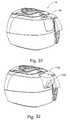
- FIG. 3is a general view of the humidifier unit
- FIG. 4is a cutaway view of the flow generator
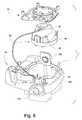
- FIG. 5is an exploded view of components of the flow generator
- FIG. 6is a vertical transverse cross-section of the flow generator
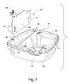
- FIG. 7is a more detailed illustration of the bottom case and power supply of FIG. 5 ;
- FIG. 8is a more detailed illustration of the chassis, chassis lid and fan housing of FIG. 5 ;
- FIG. 9is a more detailed illustration of the PCB, top case and exterior fittings of FIG. 5 ;
- FIG. 9Ais a schematic vertical cross-section detail of the connection of the handle to the flow generator top case
- FIG. 10is an underneath view of a chassis forming part of the flow generator
- FIG. 11is a vertical cross-section of the chassis through a venturi passage connecting muffler cavities of the flow generator;
- FIG. 12is a general view of a fan forming part of the flow generator
- FIG. 13is a vertical cross-section showing the fan mounting arrangement
- FIG. 14is an exploded view of a humidifier adapted for use with the flow generator of FIG. 5 ;
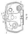
- FIG. 15is a rear view of the humidifier assembly
- FIG. 16is a perspective of a seal for the air flow path
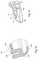
- FIG. 17is an underside perspective of the humidifier lid of FIG. 14 ;
- FIGS. 18 and 19are respectively a perspective and a detail cross section of the humidifier lid seal of FIG. 14 ;
- FIGS. 20 and 21are respectively a perspective and a longitudinal cross section of the humidifier tub lid of FIG. 14 ;
- FIG. 22is a graph of heater target temperature against humidifier setting
- FIG. 23is a schematic circuit diagram of a power control circuit to the humidifier heater
- FIG. 24illustrates reminder menus of the flow generator control
- FIGS. 25 to 34show various modular data connector arrangements
- the illustrated apparatuscomprises a flow generator 50 and a humidifier 150 , shown in their assembled condition in FIG. 1 , and separately in FIGS. 2 and 3 respectively.
- the flow generatorengages with the separable humidifier at an engagement face 52 , from which protrudes an air connector 53 for the delivery of air from the fan to the humidifier container, electrical connectors 54 for the delivery of power to the humidifier heater and an optical coupling transmitter 200 and sensor 201 described further below.
- the face 52also carries a pair of slots 55 which are engaged by corresponding tongues 156 provided on the humidifier engagement face 157 ( FIG. 15 ) by which the flow generator 50 and humidifier 150 are connected together, as will be described in more detail below.
- the flow generator 50is also provided with an LCD screen 58 and associated keys 59 by which the user can set the operating parameters of the unit.
- the flow generator 50has an external case of rigid plastics material moulded in two parts, a top case 60 and a bottom case 61 .
- the lower edge of the top case 60is stepped and flanged at 62 ( FIG. 9 ) to mate with the periphery of the bottom case 61 .
- the bottom case 61 of flow generator 50has a shell 120 of rigid plastics material, such polycarbonate/ABS blend, forming the structure of the case, integrally overmoulded with a lining 121 of an elastomer such as a synthetic rubber or thermoplastic elastomer which forms the seal 63 between the top and bottom cases and the chassis 64 and also forms the external feet of the case (see FIG. 6 ).
- a shell 120 of rigid plastics materialsuch polycarbonate/ABS blend
- the lining 121also covers the internal surface of the chassis-receiving cavity of the bottom case and the dividing wall 123 between the power supply cavity 65 and chassis-receiving cavity, the resulting composite of the rigid shell with elastomeric lining serving to reduce radiated noise levels from the flow generator by damping acoustic resonance of the walls.
- a power supply cavity 65 and a first muffler cavity 134Formed in the bottom case 61 by walls which join the outer wall of the case are the lower parts and of, respectively, a power supply cavity 65 and a first muffler cavity 134 .
- the upper parts of these cavitiesare formed by the chassis 64 , described below.
- the first muffler cavityforms part of the air flow path from the air inlet 85 to the blower, receiving air from an air inlet path defined by the chassis 64 , as described below.
- the chassis 64forms the blower or fan cavity 70 , inlet and outlet air flow paths and the top of the power supply cavity 65 .
- the fan cavity 70includes a metal liner tub 73 insert moulded into the chassis as described below.
- the chassis 64is formed with a peripheral wall 69 flanged around its lower edge to engage with the inner periphery of the overmoulded sealing flange 63 .
- the chassis 64includes a downwardly extending fan cavity 70 in which is mounted the fan 90 described below.
- This cavity 70is formed by moulded side walls 71 and base 72 , which are formed by moulding inner and outer layers of thermoplastic around an inserted steel liner tub 73 .
- the tubmay be stainless steel, nickel plated mild steel or other suitable corrosion resistant metal.
- the fan cavity 70opens to the upper surface of the chassis 64 to enable insertion of the fan 90 , this opening being closed by a lid 74 .
- the density and stiffness of the steel tubcreates a highly effective barrier to transmission of the motor and fan noise, while formation of the cavity 70 by insert moulding from differing materials provides very effective acoustic damping, as does the combination by co-moulding of the hard and soft plastics described already and further described below.
- the use of co-moulding or overmoulding in the combination of materials of different, preferably widely different, stiffness and different, preferably widely different, densityhas been found to be particularly advantageous in providing acoustic damping.
- Preferred materials for the chassis and liner tubare polypropylene thermoplastic for the chassis and metal, preferably steel (optionally stainless steel), for the liner tub.
- the applicanthas found that by forming the fan cavity as a composite of metal and polymer—having a differential in density of greater than 5 times, preferably about 7-8 times, and also significantly different stiffness and damping properties—the resonance peaks of the composite structure are well damped so that noise generated by the fan is well-suppressed by the fan cavity construction.
- the polymer for the chassis 64be a glass fibre-filled polymer containing from 10-40%, and more preferably about 30%, glass fibre.
- the use of this material as a composite with a steel liner tub 73gives both effective damping of fan noise and a good match in thermal expansion characteristics so that the composite material chassis performs well over a wide range of operating temperatures. Further, the Applicant has found that the use of glass fibres outperformed talc, bronze, glass bead filler materials for this purpose.
- the top of the fan cavityis formed by the chassis lid 74 , which is formed of an embedded steel insert overmoulded with elastomer to provide acoustic damping and sealing of the top of the fan cavity 70
- a preferred polymer lining for the lidis an elastomer, for example of the same type used for the lining 121 of the bottom case.
- the upper part of the power supply cavity 65is formed by a side wall 75 extending downwardly from the roof of the chassis 64 , which sealingly engages the opposed wall of the lower portion of this cavity.
- the lower wallis provided for this purpose with a co-moulded or overmoulded rubber sealing flange 76 .
- the interioris at the same time acoustically sealed from the power supply cavity, which may not be completely sealed from the exterior, due to the necessity of providing mains power input and low voltage power output to the humidifier, via connectors 77 and 79 mounted in apertures 78 and 80 respectively in the rear and front walls of the cavity, and if necessary the venting of the compartment to outside air for cooling. This reduces assembly time and allows the overall device to be smaller.
- a power supply unit 124is received in the power supply cavity 65 , for providing electrical power for operation of the fan, control functions and the humidifier heater pad.
- the power supplycomprises a printed circuit board 133 , to which are directly attached by soldering or other suitable means a power inlet connector 77 , a fan power outlet connector 126 for the fan motor and a humidifier power outlet 79 .
- Each end of the power supply cavity 65has mounting guides 136 for supporting the PCB of the power supply in an upright position so that installation of the power supply is achieved by drop-in assembly.
- the fan 90 and fan housing 93 , 94fit into the fan cavity 70 of the chassis and connect to electrical connector 26 at the top of the power supply PCB. Elastomer overmoulding of the base 94 of the fan housing seals the housing, provides acoustic damping of the fan housing base and forms feet on the bottom of base to act as bump stops protecting the fan in case the unit is bumped or dropped.
- a printed circuit board 81carrying the electronic control components of the unit.
- the printed circuit board 81preferably includes an LCD display 58 .
- an edge connector 1082 and a sliding connector 1082 Amay be accessible from a connector aperture in the rear of the case 60 , providing for modular connector arrangements to be described in more detail below with reference to FIGS. 25 to 34 .
- an air inlet 84is also provided in the rear wall of the top case, and this communicates with an air inlet passage 85 formed in the chassis above the roof of the upper portion of the power supply cavity 65 , this passage in turn opening to first muffler cavity 134 surrounding the bottom of the fan cavity of the chassis.
- the top casefurther defines an air inlet to the flow generator, and has a replaceable filter 129 of any suitable material, such as foam or fibre, and filter cover 130 fitted to the top case 60 .
- An inlet wedge 131serves as an airflow guide.
- a blank cover 132clips in place over apertures in the case which align with connectors 1082 , 1082 A to provide ports on the PCB for communications, etc. Further details of the communications and/other electrical ports in the flow generator case will be described later with reference to FIGS. 25 to 34 .
- connection passage 137( FIG. 11 ) into a second muffler volume formed by the space between the fan cavity 70 and the fan.
- the fan cavity and the space between the bottom case and the chassisthus form a pair of serially connected volume mufflers, with a restricted diameter passage therebetween.
- Noise attenuation produced by a muffler systemis generally proportional to the ratio of a representative diameter of the muffler volume to that of the constriction, and thus an optimal muffler design must balance optimal noise attenuation against the constraints of available muffler volume—especially in a compact machine—and avoiding unacceptable air flow restriction through the constriction.
- the Applicanthas found that a favourable adjustment of this balance may be achieved by forming the intermediate connecting passage 137 between the muffler volumes as a venturi, as shown in FIGS. 10 and 11 , with a relatively short, smoothly varying diameter lead in portion 137 a at the end adjacent the first muffler, an intermediate constriction 137 b and a gradually expanding lead out portion 137 c at the downstream end.
- the muffler systemcan achieve the noise attenuation according to the representative diameter of the smallest diameter portion, with better pressure drop characteristics.
- FIGS. 12 and 13It will now be convenient to describe the features of the fan, which are shown in FIGS. 12 and 13 .
- the fan 90comprises a motor 91 , preferably brushless DC motor, provided with a coaxial impeller 92 , mounted vertically within a fan housing consisting of a cover 93 and a base 94 .
- An air inlet 95is provided in the floor of the base 94 on the impeller axis, and cavities in the cover and base form a volute 96 which leads from the impeller to an air outlet 97 .
- the cover and base 93 and 94are joined by means of slotted tabs 98 which extend upwardly from the base to snap over stepped ribs 99 , the tabs 98 being further located by fitting between parallel ribs on the cover 93 .
- the joint between the cover 93 and the base 94is sealed by an elastomeric over- or co-moulded sealing ring 101 .
- the bottom surface of the fan housing base 94is provided with radial stiffening ribs, and overmoulded to the base 94 is an elastomer damping member 103 which covers that bottom surface between the ribs, and extends around the edge of the base by a flange portion and peripherally spaced tabs.
- an elastomer damping member 103which covers that bottom surface between the ribs, and extends around the edge of the base by a flange portion and peripherally spaced tabs.
- feet 106Moulded integrally with the rigid plastics portion of the fan housing base are feet 106 which extend proud of overmoulded elastomer member 103 to receive helical mounting springs 102 ( FIG. 13 ), preferably of metal, by which the fan is mounted on the base 72 of the fan cavity.
- the degree of size reduction which is an objective of the present inventionrequires great care to be taken to minimise the transmission of noise and vibration, particularly from the motor and the impeller of the fan 90 .
- the mounting springsare therefore chosen to ensure minimal transmission of the vibration frequencies encountered during operation. This is achieved by choosing the springs with reference to the mass of the fan 90 , such that the natural frequency of the system comprising the springs and the fan is less than approximately one tenth of the shaft speed of the motor when running at its lowest operating speed.
- the air outlet 97upon the introduction of the fan into the fan cavity, is connected by means of a thermoplastic elastomer or silicone rubber coupling member 108 with an air passage which extends from the side wall of the fan cavity to a connecting nozzle 110 extending through an aperture provided for this purpose in the front face of the flow generator.
- the coupling member 108includes at least two corrugations which provide flexibility to the connection and improved resistance against transfer of vibration from the fan to the flow generator case.
- the fan 90therefore floats within its cavity 70 in the chassis 64 with minimum acoustic coupling to the remainder of the flow generator.
- the characteristics of the mounting springs and the coupling member 108are chosen to minimise the transmission of characteristic vibration frequencies of the fan.
- the illustrated flow generator construction and materials combinationsare adapted to result in a compact CPAP flow generator unit of similar performance and noise characteristics to larger units—eg. capable of generating from 4-20 cm H 2 O pressure and a flow rate of 120 L/min and a total radiated noise volume of less than 33 dBA, more preferably less than about 30 dBA, when operating at 10 cm H 2 O—in a flow generator unit having a total volume of about 2 litres or less.
- the handle 128has opposed arms with inwardly projecting pins 140 at their distal ends.
- the top case 60includes a pair of channel-shaped tracks 141 with one open and one closed end, for receiving respective of the pins.
- the facia 127clips onto the top case 60 , and includes projections 142 which trap the pins 140 in the end of their tracks 141 .
- the handle attachment configurationthus provides a quick and simple means of assembly without requiring flexing of the handle arms to locate the pins into small recesses as in the prior art.
- the humidifier 150comprises a base unit designed for simple attachment to and detachment from the flow generator 50 , which forms a cradle for a water container which is in turn attachable to and detachable from the base unit.
- the general arrangement of the humidifier componentsincludes a base (rear cover 803 and front cover 602 ) onto which is fitted a heater comprising a heater plate (plate 632 with ceramic heater pad 800 ) which supports a water tub (tub base 698 , seal 699 and tub lid 700 ) and a hinged humidifier lid 648 which seals against the tub lid 700 to form an air path into the tub through the tub lid.
- a heatercomprising a heater plate (plate 632 with ceramic heater pad 800 ) which supports a water tub (tub base 698 , seal 699 and tub lid 700 ) and a hinged humidifier lid 648 which seals against the tub lid 700 to form an air path into the tub through the tub lid.
- the rear face of the basehas a peripheral flange 153 which seats in a corresponding peripheral recess 113 surrounding the front face of the flow generator 50 when the two units are brought together by linear movement towards each other.
- a latch 404is held in place by latch retainer 404 a to be moveable vertically and resiliently urged downwardly by spring 404 b , so that the tongues 156 engage in the slots 55 and snap home to engage the two units by means of the downwardly extending fingers 158 at the ends of the tongues.
- the PCB of the flow generatoris provided at the end adjacent the humidifier with an optical transmitter 200 which emits a periodic flash of light from the end face of the flow generator case, and an optical sensor 201 to detect the presence or absence of the humidifier.
- the rear face of the humidifiercontains a curved reflector 204 ( FIG. 15 ) which, when the humidifier is attached to the flow generator, completes an optical path from the transmitter to the sensor so that the flow generator PCB detects the presence of the humidifier and may adjust the control algorithms accordingly.
- the rear face of the base unitalso carries a connector 162 , in this embodiment a pair of flat male blade connectors, for engagement with a mating connector 114 on the front face of the flow generator, to provide power to the humidifier heater from the power supply in the power supply cavity 65 .
- the respective facesmay also carry further interconnecting devices, where other electrical or data connections are required to be established between the flow generator and the humidifier or downstream devices including the air conduit or the mask. Such devices may take the form of optically coupled devices, or connectors of other suitable kinds.
- an opto-coupling connectorenables the implementation of a simple protocol for communications between the flow generator and the humidifier. For example, the current flow levels of the flow generator can be sent to the humidifier controller which then adjusts the operation of the humidifier according to a predetermined algorithm.
- the back cover 803which fits to the rear of the front cover 602 provides the air, electrical and communications connections to the flow generator and provide support for a control PCB 804 and the catch assembly.
- the catch assemblyincludes a latch 404 which is retained by a latch retainer 404 a and spring 404 b , and operates to attach the humidifier to the flow generator generally as described for the earlier embodiments.
- a control knob 805 on the top of the front cover 602is connected to the PCB 804 to allow patient control over the degree of humidification.
- an aperture 264( FIG. 15 ) for electrical connections between the humidifier and the flow generator, or for electrical and signal connections to the humidifier.
- the air port 807 in the humidifier rear facemates with the outlet 110 of the flow generator.
- An elastomer airway seal 722fits between the front and back covers to connect the air port 807 in the back cover 803 to the aperture 626 of the front cover 602 .
- the seal(shown in more detail in FIG. 16 ) has an inlet connector portion 722 a which connects to the flow generator output via the air port 807 formed in the back cover 803 , and a peripheral seal portion 722 b which extends about the aperture 626 periphery at the front face of the cover 602 .
- a wall portion 722 c of the sealcloses off a lower part of the aperture 626 , leaving a smaller aperture 722 d defined by the seal.
- the airway seal 722defines a closed passage from the circular air port 807 to the rectangular aperture 722 d in the vertical wall of the front cover.
- the heater padcomprises lower and upper parts 806 , 800 and a heater pad cover 632 .
- the heater pad cover 632has an upper heating surface 634 , a downwardly extending peripheral wall 636 acting as a further heating surface and a rear flange with a pair of attachment portions 640 for attachment of the heater pad to tubular protrusions 628 on the rear of the front cover 602 .
- the heater pad cover 632is configured to accommodate, below the upper wall 634 and within bounds of the wall 636 , a heater pad or other heating means such as an induction heater, for causing heating of the water in the humidifier water container.
- the front of the heater pad cover 632has a forwardly extending tab 646 of dog-legged shape, which extends to the front of the humidifier cradle front cover 632 to support the heater and also provide a catch for the humidifier lid 648 .
- the water containerconsists of a water tub 698 , seal 699 and tub lid 700 .
- the floor of the tub 698is of complementary shape to the heater pad, and is formed of metal or other material suitable to conduct heat from the heater pad to the water in the tub.
- the floorhas a generally horizontal portion 900 corresponding to the upper heating surface 634 of the heater pad and a U-shaped portion below the level of the heater pad upper surface, including a generally vertical heat transfer portion 902 below the horizontal portion corresponding to the peripheral heating surface.
- the rear surface of the tub lidhas an air inlet aperture 801 leading to an inlet end of the U-shaped air passage 718 .
- the tub 698 and tub lid 700are pressed rearwards so that the peripheral seal 722 b abuts the rear surface of the tub lid in a locus surrounding the rear opening of the inlet aperture 801 , creating a sealed air path from the flow generator outlet to air passage 718 and into the headspace of the humidifier tub. This allows the humidifier tub to be removed for refilling and replaced without the need for a separate operation to connect the air flow.
- the inside wall of the tub lid 700has projections 802 a , 802 b which serve to limit the press fitting of the tub lid onto the tub base 698 .
- One projection 802 ais provided at the front of the tub, and further projections 802 b , or sets of projections, are provided on opposed side walls of the tub lid, forward of the rear of the tub.
- This positioning of the projections 802 ballows one-handed disengagement of the tub base and tub lid by squeezing together of the base and lid at their rear end, causing the connection to pivot about the side projections 802 b and the tub and lid to separate at the front.
- the ability to separate these components one-handedis a feature of considerable utility, especially for stroke patients or other users with limited dexterity.
- the water container lid 700has an air passage 718 formed as a U-shaped channel, leading to the humidified air entry aperture 720 into the headspace of the water container.
- the channel floorslopes down in the direction of air flow from the air inlet end to the end at which the air enters the water container.
- the water container lidalso has an elliptical humidified air exit aperture 722 .
- Watermay be added to the water container via the air exit aperture 801 . 1 ( FIG. 20 ) while the tub lid is in place, or by removing the tub lid.
- the tankis intended to be filled via the air exit aperture 801 . 1 , and the apparatus may be provided with a filling bottle with a spout dimensioned for a convenient fit with that outlet.
- a filling bottlewith a spout dimensioned for a convenient fit with that outlet.
- Such a bottlemay be provided with a spout of the kind incorporating an air bleed passage which will allow the tank to fill the correct predetermined height.
- filling arrangementsmay be employed, for example by removing the tub lid.
- the correct filling heightmay also indicated by filling level graduations scribed or otherwise marked on the wall of the water tub.
- a microswitch(not shown) or other sensing means may be provided to turn off power to the heater pad when the lid is opened, and/or when the water container is removed.
- FIGS. 17 to 19show the underside of the humidifier lid 648 and the seal 676 which provides a seal to the tub lid 700 about the U-shaped passage 718 and the humidified air exit aperture 716 .
- the seal 676comprises an edge seal portion 676 a and membrane portion 676 b , as shown in FIGS. 18 and 19 .
- the lid 648has an upper wall 650 and a front wall 652 which extends downwards, and outwardly, from the upper wall.
- the upper wall 650has a recess at its rear side, such that the part of the upper wall and front wall 652 on each side of the recess constitutes a rearwardly projecting arm 656 .
- the hubs 658are configured to be received in the sockets 622 of the humidifier front cover 602 such that each hub and its corresponding socket constitute a hinge connection, for attaching the lid 648 to the front cover.
- the lid 648During opening of the lid 648 , it may be freely rotated about the hubs through greater than 90° until it reaches a maximum extent of normal travel.
- the lid and front coverare configured such that, if the lid is then rotated further, the hubs pop out of the sockets 622 . This may be achieved, as would be understood by a person skilled in the art, by providing suitable chamfers on the hubs and/or sockets, or other suitable formations on the lid or cover, so that the lid flexes to release the hubs from the sockets.
- each arm 656is shaped complementarily to the shape of the upper portion of the face of the front cover to accommodate that part of the arm when the lid 648 is in a closed position.
- the lid 648includes a humidified air outlet pipe 662 which passes through the upper wall 650 and extends upwards and forwards at an acute angle from the top of the upper wall, for attachment of a hose to supply humidified air to a patient.
- the pipe 662continues below the lower surface of the upper wall 650 to define an elliptical rim 664 .
- a wall 666Extending downwards from the lower surface of the upper wall 650 is a wall 666 which is configured to define a closed path and hence a U-shaped enclosed region 668 within the confines of the wall.
- a recessed notch 674on the rear (inner) surface of that wall, for snap-fit engagement with the tab 646 of the heater pad cover to act as the catch for the lid.
- the lidmay be opened by flexing the assembly to release the tab from the notch.
- the edge seal portion 676 a of the lid sealincludes a channel 676 c which fits over the wall 664 and rim 666 on the bottom of the lid 648 , and a curved sealing flange 676 d which seals against the top surface of the tub lid, so that the space between the U-channel 718 on the tub lid and the seal membrane forms an inlet air passage of the tub, and the air outlet aperture 722 of the tub lid communicates via the elliptical opening 676 e in the lid seal to the air outlet pipe 662 of the humidifier lid 648 . This is achieved without the need to connect and disconnect air tubes to remove the water container.
- the air from the flow generatorpasses into the water container, the air then travels across the surface of the water so that the air becomes humidified.
- the heating of the water by the heating padenhances this humidification.
- the airthen exits the water container through the outlet opening 716 to the air outlet pipe 662 , which is in turn attached to a suitable hose (not shown) for supplying the humidified air to a patient.
- the air mass within the containeris caused to swirl and thus enhance the uptake of water vapour from the water contained in the tub.
- the enhanced uptake of water vapour achieved by inducing the swirling of air as it passes through the tankenables, in an alternative embodiment of the invention, the elimination of the heating of the water in the tub.
- the heating element and its controls, and the heat transfer components including the heating plate and the metal tank baseare eliminated, and the humidifier becomes a simpler, passive, device.
- a humidifier assembly in accordance with the present inventionhas a number of advantages over the prior art.
- One advantagerelates to convenience of use. Convenience of use is important for all patients, especially those who have poor dexterity.
- the base of the humidifier assemblyincludes a generally “negative” U-shaped channel.
- the bottom portion of the water tubhas a corresponding “positive” U-shape.
- the outer wall of the U-shapeis sloping, whereas the inner wall is generally vertical. Because the base and water tubs have complementary configurations, placing the water tub generally in the correct position means that it will to some extent self-align into the correct position, which as described below, is a sealing position.
- a water tub according to the present designcan be easily placed in a sealing position without requiring a patient to connect small fiddly tubes such as used in the prior art.
- An aspect of thisis that a seal is provided by placing a generally flat surface such as the rear of the water tub, or the top surface of the water tub, against respective silicone gaskets that present a corresponding flat surface. The respective seals are formed when the two flat surfaces contact.
- the humidifier assemblyhas a very convenient “drop-in” configuration.
- the water tubis held in position by the simple motion of swinging the pivoting lid through approximately 90° from fully open to closed.
- the lidis locked in position via a robust mechanism which provides and audible and reassuring “click”-sound when engaged. Whilst in the preferred embodiment, a pivoting movement is used for the lid, other movements are contemplated including sliding and translation.
- the lid of the humidifier assemblyincludes an air delivery tube connector, which in a preferred form is generally cylindrical. Connection of the air delivery tube to the lid can be achieved regardless of whether the water tub is in position. This arrangement means that the water tub can be removed and refilled with water if necessary without requiring disengagement of the air delivery tube from the humidifier assembly.
- the illustrated humidifier constructionprovides a compact humidifier adapted for ease of manufacture and use, and further provides protection against backflow of water into the flow generator when the humidifier and flow generator units are assembled together.
- Backflow protectionis provided by the sloping floor of the air passage and the location of the air inlet aperture 801 and the aperture 722 d in the seal 722 relative to the air inlet 720 from the air passage 718 into the headspace of the humidifier tub 698 .
- the tubis overfilled while in its horizontal position, the water will flow back along the U-shaped air passage 718 only as far as its forwardmost portion, which has a front wall 717 lower than the air inlet aperture 801 , and will drain towards the front of the machine.
- the waterwill be prevented from flowing back along the air passage from the tub to the air inlet 801 as the intermediate portion of the air passage 718 will be above the level of the aperture 720 . The water will then flow back into the tub once the machine is righted.
- either the air inlet aperture 720 or the air inlet 801will be above the water level and thus water should not flow back into the low generator. Again, any water which escapes the tub will flow back into the tub once the machine is righted.
- a non-return valveat an appropriate point, for example a flexible membrane supported in the mouth of the humidifier air inlet.
- the contour of the lid sealis adapted to collect condensation which may form in the lid cavity and the headspace of the water receptacle, preventing backflow of this condensation to the flow generator when the lid is opened.
- the configuration of the front and back covers of the humidifier and of the heater padis adapted to allow fitting together in a vertical orientation, to minimise the need for reorientation during assembly of the humidifier unit on the production line.
- the resilience of the connection between the lid and the water receptacle, provided by the lid sealis adapted to maintain downwards pressure on the water receptacle when the lid is closed, to maintain good heat-transfer contact between the base of the water receptacle and the heater pad without the added complexity and expense of spring-loaded mounting of the heater pad.
- the humidifieris provided with a control knob allowing adjustment of the humidity of the air supply to the patient.
- the control knobmay have a smoothly variable control, or a series of discrete humidity settings, and will have an ‘off’ setting where no power is supplied to the heating pad.
- the correlation between the humidity setting and the power to the heateris controlled by a circuit on the PCB 804 .
- FIG. 22is a sketch of a preferred calibration curve of target water container temperature (y axis) against humidity setting (x axis), including upper and lower tolerances.
- the heater controlselects a very low target heater temperature—less than ambient temperature, and preferably lower than the lowest operating temperature of the humidifier. In this way, the heating is turned off when the control knob is in its off position, while allowing use of a less expensive potentiometer without an integral off switch or a separate on/off switch.
- the mounting of the control knob mechanismmay provide a tactile ‘click’ at the off position of the control knob, to confirm to the user that the heater is turned off.
- FIG. 23is a circuit diagram of the humidifier control circuit for controlling the water temperature, including a potentiometer POT 1 actuated by the control knob 805 and an operational amplifier OA 1 providing power to the heater 800 .
- the potentiometeris used in the control path of a semiconductor arrangement to set the operating temperature. This substantially reduces the current through the potentiometer because the potentiometer now only carries a semiconductor control current rather than the load current required to drive the heater element.
- the potentiometeris used in conjunction with a temperature sensing element to control an operational amplifier which drives the heater directly or through a high current semiconductor switch.
- FIG. 23shows an arrangement for controlling temperature via an operational amplifier OA 1 .
- the operational amplifier n 1has a pair of inputs, V+ being an adding input and V ⁇ being a subtracting input.
- the output of the amplifieris proportional to the difference between the voltages on the inputs V+ and V ⁇ .
- the temperature of the wateris sensed by temperature sensitive resistive element, thermistor TH 1 , and the operating point is set by potentiometer POT 1 .
- the operational amplifier input V+is connected to the junction of R 106 and thermistor TH 1 .
- the operational amplifier switching thresholdis determined by the ratio of the resistance of the potentiometer POT 1 plus resistor R 106 to the resistance of the resistance network formed by thermistor TH 1 plus resistor R 11 in parallel with resistor R 10 plus resistor R 10 equals the ratio of resistor R 17 to resistor R 21 . That is, the operational amplifier switches when the junction between the thermistor TH 1 and resistor R 106 crosses over the potential at V ⁇ .
- the operational amplifieris powered from supply points Vss and Vo, so the drive current does not pass through the potentiometer.
- Vssmay be the same as Vs
- Vomay be the same as 0v.
- the operational amplifiermay drive the heater element directly or it may control a power transistor which drives the heater element.
- This arrangementsignificantly reduces the dissipation through the potentiometer, allowing a smaller potentiometer, with smaller cooling needs, to be used.
- the arrangementis also well adapted for use in implementing the ‘soft’ off setting arrangement described above with reference to FIG. 22 .
- FIG. 24is a flowchart of a Reminder menu to set a number of reminders to alert the patient to specific events; for example, when to replace their mask, when to insert a Data Card (if their device is Data Card enabled) and so on. It can also be used to set special customised reminders.
- a reminderWhen a reminder is due, a message is displayed on the LCD and remains whenever the device is not delivering therapy.
- the backlight on the LCDflashes when a message is displayed. If more than one reminder for a patient is scheduled for the same date, all scheduled reminders are displayed during that day.
- a patientcan clear a message by pressing the LEFT key (or inserting a Data Card, in the case of the Data Card reminder).
- the default setting for all remindersis that they are disabled.
- the patiententers the Reminder Menu from the standby screen by pressing LEFT and DOWN for at least three seconds.
- FIG. 24summarises the Reminder Menu screens:
- REPLACE MASKto set a timed reminder to remind a patient when they need to replace their mask.
- the patientcan press the LEFT (clear) key to remove the message from the LCD.
- CALL PROVIDERto set a reminder for the patient to phone the therapist at a certain time; for example, to discuss how their therapy is going.
- the patientcan press the LEFT (clear) key to remove the message from the LCD.
- INSERT CARDif a patient's flow generator is Data Card enabled, the therapist can set a timed reminder on the flow generator to remind them that they need to insert a Data Card to transfer patient data. This enables the therapist to establish compliance. The patient should actually insert the Data Card in order to clear the message from the LCD. (They can also press the LEFT (clear) key to remove the message.)
- REPLACE FILTERto set a timed reminder to remind the patient when to replace the air filter.
- the patientcan press the LEFT (clear) key to remove the message from the LCD.
- FIGS. 25 to 32are rear views of the flow generator, showing various forms of modular data connections foreshadowed earlier, utilising the slot 83 in the rear of the flow generator housing.
- the slot 83is provided in the wall of a rectangular recess 1115 .
- An arcuate depression 1123is provided in the upper surface of the unit above the recess 1115 to facilitate removal of closure elements from the depression, as described below.
- an edge connector 1082 and a sliding connector 1082 Aare aligned with and accessible through the connector slot 83 in the rear of the case 60 , providing for the modular connector arrangements to be described in more detail below.
- the slot 83is closed off by a blank closure element 132 , shaped to fit into the recess 1115 .
- the closure elementis shown in more detail in FIG. 27 . This element snaps into the recess by means of lower tabs 1118 and an upper tab 1119 which fit corresponding depressions such as 1122 in the walls of the recess 1115 , to close the slot 83 and conform to the contours of the surrounding surface of the unit.
- Complementarily shaped closure elementscan be provided for the reception of different kinds of data devices. Shown in FIG. 28 is an element 1116 a provided with a slot for the reception of a smart card 1120 .
- the element 1116 a or the printed circuit board itselfmay carry the necessary smart card socket.
- FIG. 29Shown in FIG. 29 is a closure element 1116 b provided with a DB type data socket.
- the element 1116 bis contoured to provide a lower front recess 1121 to facilitate gripping of the associated plug.
- FIG. 29AA cross-section of a modified form of this arrangement is shown in FIG. 29A , illustrating the connection between the internal connector 1086 of the element 1116 b and the edge connector 1082 of the PCB, and the external DB 9 connector 1088 .
- element 1116can be provided to enable the connection of devices such as memory cards and pre-programmed devices as required.
- This facilityfurthermore enables a wide range of devices to be integrated with the apparatus in modular fashion, for example a clock display which may utilise the system clock contained in the flow generator controller, a voice activation unit, oximetry, ECG and other diagnostic aids, a sound recorder, a light.
- FIGS. 30 to 32are a series of rear perspective views of the flow generator, illustrating one embodiment of the modular data connector arrangement.
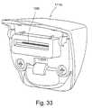
- FIG. 33shows the front, inner surface of the USB closure element module, and
- FIG. 34is a vertical cross-section of the flow generator.
- FIG. 30shows the slot 83 open, exposing the edge connector 1082 and sliding connector (not visible in this view) at the rear of the flow generator PCB 81 .
- the connectors 1082 , 1082 Acomprise a plurality of electrical contacts for carrying data and/or power between the PCB and an external device.
- FIG. 31shows the arrangement of FIG. 31 where no data connection is required, with the slot covered by a blank closure element 132 generally as described above with reference to FIGS. 25 to 27 .
- FIG. 32shows a removable closure element module 1116 c carrying a standard universal serial bus (USB) port 1084 on its rear surface.
- the element 1116 cincorporates an electrical/data pathway to an electrical connector 1090 at its forward, inner surface ( FIGS. 33 and 34 ) adapted to connect with all or selected ones of the contacts of the PCB connector 1082 for electrical and/or data transmission.
- the closure module 1116 chas internal electrical components completing a data and/or electrical pathway between its internal and external connectors so that the module acts as an adaptor between the PCB connector and a standard USB port.
- the cost and size of the flow generator unitmay be reduced as the unit may be provided with only those connectors which are needed by that patient, and additional connector modules supplied only if the need arises. Furthermore, the arrangement facilitates upgrade of the data connection arrangement of the flow generator to keep up with technological advances or changes in global data connection standards.
- the word “comprising”is to be understood in its “open” sense, that is, in the sense of “including”, and thus not limited to its “closed” sense, that is the sense of “consisting only of”.
- a corresponding meaningis to be attributed to the corresponding words “comprise, comprised and comprises where they appear.
Landscapes
- Health & Medical Sciences (AREA)
- Emergency Medicine (AREA)
- Pulmonology (AREA)
- Engineering & Computer Science (AREA)
- Anesthesiology (AREA)
- Biomedical Technology (AREA)
- Heart & Thoracic Surgery (AREA)
- Hematology (AREA)
- Life Sciences & Earth Sciences (AREA)
- Animal Behavior & Ethology (AREA)
- General Health & Medical Sciences (AREA)
- Public Health (AREA)
- Veterinary Medicine (AREA)
- Air Humidification (AREA)
Abstract
Description
- a flow generator case;
- a powered gas flow generator within the case;
- a power supply unit adapted for drop-in assembly in said case, said power supply unit including a printed circuit board, a power input connector rigidly attached to said printed circuit board and a power output connector, and
- a power supply unit mounting for mounting said power supply unit in said case such that said power input connector aligns with a power input port of said case.
- a cavity within a chassis of the flow generator, the cavity defined by side walls and base, the enclosure being adapted to receive and mount a blower in said cavity and
- a lid adapted to be mounted on said chassis so as to form a top surface of the cavity,
wherein at least one of the chassis and lid is moulded from a composite comprising a metal and a plastic.
- a water container,
- a heater located in heat transfer communication with said water container,
- a gas flow path including a gas inlet, a humidified gas outlet and an intermediate gas flow path which contacts the gas with water vapour from said container,
further including a drainage opening adjacent said heater allowing drainage of water past the heater to exit said humidifier case.
- a humidifier case,
- a water container,
- a heater pad located in heat transfer communication with said water container,
- a gas flow path including a gas inlet, a humidified gas outlet and an intermediate gas flow path which contacts the gas with water vapour from said container,
wherein said heater pad has an upper heating surface and a peripheral heating surface which includes a side wall of said heater pad, and wherein a heat transfer surface of said water container is shaped to correspond to said heater pad so as maintain close heat transfer communication with said upper heating surface and peripheral heating surface of said heater pad.
- a humidifier case having a hinged lid,
- a water container adapted for drop-in assembly in said case,
- a heater in heat transfer communication with said water container,
- a gas flow path including a gas inlet, a humidified gas outlet and an intermediate gas flow path which contacts the gas with water vapour from said container,
wherein said water container has a gas passage inlet communicating with said gas flow path,
said humidifier further including a gas passage inlet seal for sealing connection said gas passage inlet to said gas flow path, wherein said sealing connection is actuated by drop-in assembly of said water container and hinged closing of said lid.
- placing the water tub in the tub-receiving-portion of the base so as to position the inlet and the outlet adjacent one another;
- closing the hinged lid; and
- engaging the locking mechanism.
- closing the hinged lid; and
- engaging the locking mechanism.
- a humidifier case having a lid,
- a water container within said case,
- a heater in heat transfer communication with said water container,
- a gas flow path including a gas inlet, a humidified gas outlet in said lid and an intermediate gas flow path which contacts the gas with water vapour from said container, and
- a gas outlet seal operatively associated with said lid whereby closing said lid creates a sealed communication between said humidified gas outlet the seal and a gas space of said water container.
- a water container,
- a heater in heat transfer communication with said water container,
- a gas flow path including a gas inlet, a humidified gas outlet in said lid and an intermediate gas flow path which contacts the gas with water vapour from said container,
- wherein said intermediate gas flow path includes a gas passage between a gas passage inlet and a gas inlet to said gas space, said gas passage having a floor sloping downwards from said gas passage inlet to said gas inlet.
- a water container,
- a gas flow path including a gas inlet, a humidified gas outlet in said lid and an intermediate gas flow path which contacts the gas with water vapour from said container,
wherein said gas flow path is adapted to introduce said gas into a headspace of said water container with a swirling motion.
- a flow generator case including an aperture;
- a gas flow generator;
- a control circuit for said flow generator, said circuit including a connector positioned to be accessible through said aperture for data or electrical communication with an external device; and
- a plurality of closure modules each adapted to attach to said case to cover said aperture, at least one of said closure modules including an internal connector adapted to connect with said control circuit connector, an external data or electrical port adapted for connection to said external device and a data or electrical pathway between said internal and external connectors.
P=V2/R
where V=the supply voltage and is normally fixed and R=RH+RP
where RH is the resistance of the heater and is fixed and RP is the resistance of the potentiometer which is variable and provides the temperature control. The current is: I=V/R, and the proportion of heat through the potentiometer is I2*RP=RP*V2/(RP+RH)2. The remainder of the heat is used by the heater element to heat the water.
Vref=Vs*R12/(R12+R17)
Claims (173)
Priority Applications (16)
| Application Number | Priority Date | Filing Date | Title |
|---|---|---|---|
| US12/659,963US10293125B2 (en) | 2003-06-20 | 2010-03-26 | Flow generator with patient reminder |
| US12/900,008US8020551B2 (en) | 2003-06-20 | 2010-10-07 | Breathable gas apparatus with humidifier |
| US12/900,781US8028693B2 (en) | 2003-06-20 | 2010-10-08 | Breathable gas apparatus with humidifier |
| US13/080,300US8042535B2 (en) | 2003-06-20 | 2011-04-05 | Breathable gas apparatus with humidifier |
| US14/445,152US9038632B2 (en) | 2003-06-20 | 2014-07-29 | Breathable gas apparatus with humidifier |
| US14/445,143US9038631B2 (en) | 2003-06-20 | 2014-07-29 | Breathable gas apparatus with humidifier |
| US14/445,190US9227035B2 (en) | 2003-06-20 | 2014-07-29 | Breathable gas apparatus with humidifier |
| US14/501,253US9072860B2 (en) | 2003-06-20 | 2014-09-30 | Breathable gas apparatus with humidifier |
| US14/790,693US9358359B2 (en) | 2003-06-20 | 2015-07-02 | Breathable gas apparatus with humidifier |
| US14/987,275US9539409B2 (en) | 2003-06-20 | 2016-01-04 | Breathable gas apparatus with humidifier |
| US15/054,820US9610420B2 (en) | 2003-06-20 | 2016-02-26 | Breathable gas apparatus with humidifier |
| US15/079,098USRE46543E1 (en) | 2003-06-20 | 2016-03-24 | Breathable gas apparatus with humidifier |
| US15/364,874US10881820B2 (en) | 2003-06-20 | 2016-11-30 | Breathable gas apparatus with humidifier |
| US15/869,491US10201676B2 (en) | 2003-06-20 | 2018-01-12 | Breathable gas supply apparatus |
| US16/893,663US10850053B2 (en) | 2003-06-20 | 2020-06-05 | Breathable gas supply apparatus |
| US17/852,962US20230007968A1 (en) | 2003-06-20 | 2022-06-29 | Device, system, and/or method for treating and monitoring a patient |
Applications Claiming Priority (8)
| Application Number | Priority Date | Filing Date | Title |
|---|---|---|---|
| AU2003903139 | 2003-06-20 | ||
| AU2003903139AAU2003903139A0 (en) | 2003-06-20 | 2003-06-20 | Breathable gas apparatus with humidifier |
| AU2003905136 | 2003-09-22 | ||
| AU2003905136AAU2003905136A0 (en) | 2003-09-22 | Breathable Gas Apparatus with Humidifier | |
| AU2004901008AAU2004901008A0 (en) | 2004-02-27 | Breathable Gas Apparatus with Humidifier | |
| AU2004901008 | 2004-02-27 | ||
| AU2004248855AAU2004248855B8 (en) | 2003-06-20 | 2004-06-21 | Breathable gas apparatus with humidifier |
| PCT/AU2004/000810WO2004112873A1 (en) | 2003-06-20 | 2004-06-21 | Breathable gas apparatus with humidifier |
Related Parent Applications (1)
| Application Number | Title | Priority Date | Filing Date |
|---|---|---|---|
| PCT/AU2004/000810A-371-Of-InternationalWO2004112873A1 (en) | 2003-06-20 | 2004-06-21 | Breathable gas apparatus with humidifier |
Related Child Applications (4)
| Application Number | Title | Priority Date | Filing Date |
|---|---|---|---|
| US12/659,963ContinuationUS10293125B2 (en) | 2003-06-20 | 2010-03-26 | Flow generator with patient reminder |
| US12/900,008ContinuationUS8020551B2 (en) | 2003-06-20 | 2010-10-07 | Breathable gas apparatus with humidifier |
| US12/900,781ContinuationUS8028693B2 (en) | 2003-06-20 | 2010-10-08 | Breathable gas apparatus with humidifier |
| US13/080,300ContinuationUS8042535B2 (en) | 2003-06-20 | 2011-04-05 | Breathable gas apparatus with humidifier |
Publications (2)
| Publication Number | Publication Date |
|---|---|
| US20080072900A1 US20080072900A1 (en) | 2008-03-27 |
| US8006691B2true US8006691B2 (en) | 2011-08-30 |
Family
ID=35976816
Family Applications (2)
| Application Number | Title | Priority Date | Filing Date |
|---|---|---|---|
| US10/533,940Active2027-08-31US8006691B2 (en) | 2003-06-20 | 2004-06-21 | Humidifier with removable water tank |
| US12/659,963Expired - LifetimeUS10293125B2 (en) | 2003-06-20 | 2010-03-26 | Flow generator with patient reminder |
Family Applications After (1)
| Application Number | Title | Priority Date | Filing Date |
|---|---|---|---|
| US12/659,963Expired - LifetimeUS10293125B2 (en) | 2003-06-20 | 2010-03-26 | Flow generator with patient reminder |
Country Status (7)
| Country | Link |
|---|---|
| US (2) | US8006691B2 (en) |
| EP (1) | EP1648544B1 (en) |
| CN (1) | CN1809397B (en) |
| AU (6) | AU2003903139A0 (en) |
| CA (1) | CA2528314C (en) |
| NZ (1) | NZ544765A (en) |
| WO (1) | WO2004112873A1 (en) |
Cited By (67)
| Publication number | Priority date | Publication date | Assignee | Title |
|---|---|---|---|---|
| US20090020117A1 (en)* | 2007-07-18 | 2009-01-22 | Drager Medical Ag & Co. Kg | Breathing gas supply device |
| US20090194106A1 (en)* | 2005-08-15 | 2009-08-06 | Resmed Ltd. | Humidifier and/or flow generator for CPAP device |
| US20090229606A1 (en)* | 2005-08-15 | 2009-09-17 | Resmed Ltd. | Low cost cpap flow generator and humidifier assembly |
| US20090320842A1 (en)* | 2006-09-07 | 2009-12-31 | Renee Frances Doherty | Mask and flow generator system |
| US20110139154A1 (en)* | 2005-12-21 | 2011-06-16 | Resmed Limited | Identification system and method for mask and ventilator components |
| US20110162649A1 (en)* | 2006-11-06 | 2011-07-07 | Venkata Subbarao Potharaju | Method and apparatus for increasing therapy compliance |
| USD658755S1 (en)* | 2005-08-15 | 2012-05-01 | Resmed Limited | Flow generator |
| US20120167880A1 (en)* | 2009-09-11 | 2012-07-05 | Koninklijke Philips Electronics N.V. | Humifidier with wireless temperature sensing |
| USD675730S1 (en)* | 2004-06-18 | 2013-02-05 | Resmed Limited | Air delivery device |
| US20140041663A1 (en)* | 2001-12-10 | 2014-02-13 | Resmed Limited | Multiple stage blowers and volutes therefor |
| US20140137861A1 (en)* | 2005-08-01 | 2014-05-22 | Weinmann Geräte für Medizin GmbH & Co. KG | Ventilator device |
| US8789525B2 (en) | 2007-06-07 | 2014-07-29 | Resmed Limited | Tub for humidifier |
| US8839791B2 (en) | 2011-06-22 | 2014-09-23 | Breathe Technologies, Inc. | Ventilation mask with integrated piloted exhalation valve |
| US20140299130A1 (en)* | 2013-03-15 | 2014-10-09 | Human Design Medical, Llc | Portable positive airway pressure apparatus and method for attenuating the noise emitted therefrom |
| US20150040897A1 (en)* | 2011-10-01 | 2015-02-12 | Hamilton Bonaduz Ag | Respiratory Humidifier |
| US9038632B2 (en) | 2003-06-20 | 2015-05-26 | Resmed Limited | Breathable gas apparatus with humidifier |
| US9038634B2 (en) | 2011-06-22 | 2015-05-26 | Breathe Technologies, Inc. | Ventilation mask with integrated piloted exhalation valve |
| US20150197378A1 (en)* | 2012-09-25 | 2015-07-16 | Fisher & Paykel Healthcare Limited | Lid construction for breathing apparatus |
| US9162035B2 (en) | 2005-03-01 | 2015-10-20 | Resmed Limited | Recognition system for an apparatus that delivers breathable gas to a patient |
| US9272116B2 (en) | 1999-08-05 | 2016-03-01 | Resmed R&D Germany Gmbh | Apparatus for humidifying a respiratory gas |
| US9486602B2 (en) | 2011-06-22 | 2016-11-08 | Breathe Technologies, Inc. | Ventilation mask with integrated piloted exhalation valve and method of ventilating a patient using the same |
| US9517367B2 (en) | 2013-02-01 | 2016-12-13 | 3M Innovative Properties Company | Respiratory mask having a clean air inlet chamber |
| USD787036S1 (en)* | 2015-02-13 | 2017-05-16 | Samsung Electronics Co., Ltd. | Bucket for dehumidifier |
| USD790683S1 (en)* | 2015-03-11 | 2017-06-27 | Resmed Limited | Pressurized air delivery console |
| USD791925S1 (en)* | 2015-07-13 | 2017-07-11 | Samsung Electronics Co., Ltd | Water box for dehumidifier |
| USD794173S1 (en)* | 2015-02-13 | 2017-08-08 | Samsung Electronics Co., Ltd | Bucket for dehumidifier |
| US20170361053A1 (en)* | 2014-12-18 | 2017-12-21 | Koninklijke Philips N.V. | Liquid chamber decoupling system and method |
| US9861778B2 (en) | 2013-03-15 | 2018-01-09 | Resmed Limited | Humidifier reservoir |
| US9878121B2 (en) | 2013-03-13 | 2018-01-30 | Breathe Technologies, Inc. | Ventilation mask with heat and moisture exchange device |
| US9950202B2 (en) | 2013-02-01 | 2018-04-24 | 3M Innovative Properties Company | Respirator negative pressure fit check devices and methods |
| USD816209S1 (en) | 2016-03-28 | 2018-04-24 | 3M Innovative Properties Company | Respirator inlet port connection seal |
| US10030961B2 (en) | 2015-11-27 | 2018-07-24 | General Electric Company | Gap measuring device |
| US10058673B1 (en) | 2012-09-07 | 2018-08-28 | Fisher & Paykel Healthcare Limited | Humidification chamber for a respiratory assistance apparatus |
| USD827810S1 (en) | 2016-03-28 | 2018-09-04 | 3M Innovative Properties Company | Hardhat suspension adapter for half facepiece respirators |
| USD842982S1 (en) | 2016-03-28 | 2019-03-12 | 3M Innovative Properties Company | Hardhat suspension adapter for half facepiece respirators |
| USD844787S1 (en)* | 2015-12-28 | 2019-04-02 | Resmed Limited | Pressurized air delivery console |
| US10293125B2 (en) | 2003-06-20 | 2019-05-21 | Resmed Limited | Flow generator with patient reminder |
| US10342950B2 (en) | 2013-03-15 | 2019-07-09 | ResMed Pty Ltd | Humidifier reservoir |
| USD857189S1 (en) | 2016-03-11 | 2019-08-20 | ResMed Pty Ltd | Battery pack for an air delivery module |
| US10584811B2 (en) | 2009-12-30 | 2020-03-10 | Carl J Garrett | Tapered helically reinforced hose and its manufacture |
| US10584812B2 (en) | 2008-05-07 | 2020-03-10 | Globalmed, Inc. | Stretch hose and hose production method |
| US10792454B2 (en) | 2017-01-30 | 2020-10-06 | Globalmed, Inc. | Heated respiratory hose assembly |
| USD901769S1 (en)* | 2016-07-07 | 2020-11-10 | Calor | Water tank base |
| US10859188B2 (en) | 2009-01-15 | 2020-12-08 | Globalmed, Inc. | Stretch hose and hose production method |
| US10894141B2 (en) | 2007-10-05 | 2021-01-19 | Vapotherm, Inc. | Hyperthermic humidification system |
| US10905837B2 (en) | 2015-04-02 | 2021-02-02 | Hill-Rom Services Pte. Ltd. | Respiratory therapy cycle control and feedback |
| US10918822B2 (en) | 2007-07-18 | 2021-02-16 | Vapotherm, Inc. | Humidifier for breathing gas heating and humidification system |
| US11020619B2 (en) | 2016-03-28 | 2021-06-01 | 3M Innovative Properties Company | Multiple chamber respirator sealing devices and methods |
| US11052268B2 (en) | 2013-02-01 | 2021-07-06 | 3M Innovative Properties Company | Respirator negative pressure fit check devices and methods |
| US11135393B2 (en) | 2016-05-02 | 2021-10-05 | Fisher & Paykel Healthcare Limited | Humidification chamber and chamber seal for a respiratory assistance apparatus |
| US11141552B2 (en) | 2013-03-15 | 2021-10-12 | Breas Medical, Inc. | Systems and methods for providing low-noise positive airway pressure |
| US11219787B2 (en) | 2016-03-28 | 2022-01-11 | 3M Innovative Properties Company | Respirator fit check sealing devices and methods |
| WO2022034586A1 (en)* | 2020-08-11 | 2022-02-17 | Sodastream Industries Ltd. | Respiratory machine |
| US11278700B2 (en) | 2015-06-24 | 2022-03-22 | Fisher & Paykel Healthcare Limited | Breathing assistance apparatus |
| US11332385B2 (en) | 2016-12-31 | 2022-05-17 | Ugsi Solutions, Inc. | Systems and methods for removing volatile compounds from water-storage tanks |
| US11338105B2 (en) | 2018-03-27 | 2022-05-24 | Globalmed, Inc. | Respiratory humidification device |
| US11401974B2 (en) | 2017-04-23 | 2022-08-02 | Fisher & Paykel Healthcare Limited | Breathing assistance apparatus |
| US11400247B2 (en) | 2016-12-22 | 2022-08-02 | Fisher & Paykel Healthcare Limited | Breathing assistance apparatus |
| US11534565B2 (en) | 2012-12-18 | 2022-12-27 | Fisher & Paykel Healthcare Limited | Impeller and motor assembly |
| US11571536B2 (en) | 2011-07-13 | 2023-02-07 | Fisher & Paykel Healthcare Limited | Impeller and motor assembly |
| USD1017503S1 (en)* | 2023-11-03 | 2024-03-12 | Dcstar Inc. | Tank |
| US11992078B2 (en) | 2016-03-28 | 2024-05-28 | 3M Innovative Properties Company | Headwear suspension attachment element |
| US12053588B2 (en) | 2014-12-31 | 2024-08-06 | Vapotherm, Inc. | Systems and methods for humidity control |
| US12194244B2 (en) | 2018-12-18 | 2025-01-14 | ResMed Pty Ltd | Humidifier reservoir |
| USD1060658S1 (en) | 2020-12-28 | 2025-02-04 | ResMed Asia Pte. Ltd. | Patient interface |
| US12268818B2 (en) | 2006-11-06 | 2025-04-08 | Fisher & Paykel Healthcare Limited | Integrated humidifier chamber and lid |
| US12271585B2 (en) | 2017-12-08 | 2025-04-08 | Fisher & Paykel Healthcare Limited | Graphical user interface for a flow therapy apparatus |
Families Citing this family (180)
| Publication number | Priority date | Publication date | Assignee | Title |
|---|---|---|---|---|
| US5915379A (en) | 1997-03-14 | 1999-06-29 | Nellcor Puritan Bennett Incorporated | Graphic user interface for a patient ventilator |
| DE10139881B4 (en)* | 2001-08-20 | 2017-06-08 | Resmed R&D Germany Gmbh | Apparatus for supplying a breathing gas and method for controlling the same |
| FR2875138B1 (en)* | 2004-09-15 | 2008-07-11 | Mallinckrodt Dev France Sa | CONTROL METHOD FOR A HEATING HUMIDIFIER |
| DE102005000819B4 (en)* | 2005-01-05 | 2016-04-14 | Resmed R&D Germany Gmbh | Apparatus for administering a breathable gas at a pressure level above ambient pressure |
| US7195014B2 (en)* | 2005-03-22 | 2007-03-27 | Hoffman Laboratories, Llc | Portable continuous positive airway pressure system |
| US20060231097A1 (en)* | 2005-04-02 | 2006-10-19 | Dougherty Timothy R | Apparatus for CPAP therapy |
| US20060237014A1 (en)* | 2005-04-22 | 2006-10-26 | Makinson Ian D | Breathing assistance apparatus |
| CN101252966B (en) | 2005-05-26 | 2012-07-18 | 菲舍尔和佩克尔保健有限公司 | Breathing assistance apparatus |
| DE102005031388B4 (en) | 2005-07-05 | 2017-05-04 | Resmed Limited | Device for conveying a respiratory gas |
| USD553228S1 (en) | 2005-07-29 | 2007-10-16 | Resmed Limited | Humidifier tub inlet box seal |
| WO2007019626A1 (en) | 2005-08-15 | 2007-02-22 | Resmed Ltd | Humidifier tub for cpap device |
| WO2007019627A1 (en) | 2005-08-15 | 2007-02-22 | Resmed Ltd | Compliant coupling or adaptor |
| US8522782B2 (en) | 2005-09-12 | 2013-09-03 | Mergenet Medical, Inc. | High flow therapy device utilizing a non-sealing respiratory interface and related methods |
| US11497407B2 (en) | 2005-09-12 | 2022-11-15 | ResMed Pty Ltd | High flow therapy device utilizing a non-sealing respiratory interface and related methods |
| US11458270B2 (en) | 2005-09-12 | 2022-10-04 | ResMed Pty Ltd | High flow therapy device utilizing a non-sealing respiratory interface and related methods |
| US11833301B2 (en) | 2005-09-12 | 2023-12-05 | ResMed Pty Ltd | High flow therapy device utilizing a non-sealing respiratory interface and related methods |
| US11717174B2 (en) | 2005-09-12 | 2023-08-08 | ResMed Pty Ltd | High flow therapy device utilizing a non-sealing respiratory interface and related methods |
| US11696992B2 (en) | 2005-09-12 | 2023-07-11 | ResMed Pty Ltd | High flow therapy device utilizing a non-sealing respiratory interface and related methods |
| US7677246B2 (en)* | 2005-09-23 | 2010-03-16 | Ric Investments, Llc | Modular pressure support system |
| US8997740B2 (en) | 2005-09-27 | 2015-04-07 | Ric Investments, Llc | Humidifier with back-flow prevention valve |
| US8985105B2 (en)* | 2005-10-21 | 2015-03-24 | Compumedics Medical Innovation Pty Ltd | Apparatus for delivery of pressurised gas |
| EP3045196B1 (en) | 2005-10-28 | 2018-12-12 | ResMed Motor Technologies Inc | Single or multiple stage blower and nested volute(s) and/or impeller(s) therefor |
| USD577807S1 (en) | 2006-10-27 | 2008-09-30 | Resmed Limited | Impeller |
| AU2006348403A1 (en) | 2005-12-14 | 2008-05-22 | Mergenet Medical Inc. | High flow therapy device |
| CN101325979B (en) | 2005-12-15 | 2013-08-28 | 菲舍尔和佩克尔保健有限公司 | Breathing assistance apparatus |
| US20090199857A1 (en)* | 2006-03-01 | 2009-08-13 | Resmed Limited | Method and Apparatus for Reminding user to Replace and/or Service Cpap Apparatus and/or Component Thereof |
| USD577109S1 (en) | 2006-04-05 | 2008-09-16 | Resmed Limited | Adaptor seal |
| BRPI0709500A2 (en) | 2006-04-10 | 2011-07-26 | Aeiomed Inc | apparatus for providing positive airway pressure for the treatment of sleep apnea, chronic pulmonary obstruction and snoring, and method for providing positive air pressure for the treatment of sleep apnea, chronic pulmonary obstruction and snoring |
| US8021310B2 (en) | 2006-04-21 | 2011-09-20 | Nellcor Puritan Bennett Llc | Work of breathing display for a ventilation system |
| US11318267B2 (en) | 2006-09-12 | 2022-05-03 | ResMed Pty Ltd | High flow therapy device utilizing a non-sealing respiratory interface and related methods |
| US7784461B2 (en) | 2006-09-26 | 2010-08-31 | Nellcor Puritan Bennett Llc | Three-dimensional waveform display for a breathing assistance system |
| DE102006045739B3 (en)* | 2006-09-27 | 2007-08-30 | Dräger Medical AG & Co. KG | Respiration device for patient, has connection device provided between operating and control units of respirator and humidifier, where device transmits data between control units and has additional unit for transmitting electric energy |
| AU2014200733B2 (en)* | 2008-07-29 | 2015-12-17 | Fisher & Paykel Healthcare Limited | Method and apparatus for increasing therapy compliance |
| AU2015264874B2 (en)* | 2008-07-29 | 2017-09-28 | Fisher & Paykel Healthcare Limited | Method and apparatus for increasing therapy compliance |
| AU2014233632B2 (en)* | 2006-11-06 | 2017-05-25 | Fisher & Paykel Healthcare Limited | Integrated humidifier chamber and lid |
| EP2079505B1 (en) | 2006-11-08 | 2020-07-15 | ResMed Pty Ltd | Conduit for use in a respiratory apparatus |
| AU2008208148B2 (en)* | 2007-01-23 | 2014-04-17 | Fisher & Paykel Healthcare Limited | Humidification apparatus having RFID tag sensor at patient end of gas pathway |
| AU2008202487B2 (en)* | 2007-06-05 | 2013-07-04 | Resmed Motor Technologies Inc. | Blower with Bearing Tube |
| CN101690385B (en) | 2007-06-05 | 2015-05-27 | 瑞思迈有限公司 | Electric heater, in particular for humidification and liquid heating |
| USD798437S1 (en) | 2007-07-30 | 2017-09-26 | Fisher & Paykel Healthcare Limited | Breathing apparatus |
| AU2008319519A1 (en) | 2007-10-30 | 2009-05-07 | Fisher & Paykel Healthcare Limited | Fan unit with bypass vent holes |
| EP2217312A4 (en) | 2007-11-05 | 2017-12-06 | ResMed Ltd. | Ventilation system and control thereof |
| NZ602818A (en)* | 2008-01-31 | 2014-01-31 | Resmed Ltd | Respiratory apparatus |
| NZ783425A (en)* | 2008-03-04 | 2022-12-23 | ResMed Pty Ltd | Mask system |
| US9802022B2 (en) | 2008-03-06 | 2017-10-31 | Resmed Limited | Humidification of respiratory gases |
| EP2363163A1 (en)* | 2008-03-27 | 2011-09-07 | Nellcor Puritan Bennett LLC | Device for controlled delivery of breathing gas to a patient using multiple ventilation parameters |
| EP2257328A2 (en)* | 2008-03-27 | 2010-12-08 | Nellcor Puritan Bennett LLC | Breathing assistance systems with lung recruitment maneuvers |
| AU2009251939B2 (en) | 2008-05-27 | 2015-08-06 | Fisher & Paykel Healthcare Limited | Control of humidifier chamber temperature for accurate humidity control |
| USD659235S1 (en)* | 2008-06-19 | 2012-05-08 | Resmed Limited | Positive airway pressure delivery device |
| WO2010003064A1 (en) | 2008-07-02 | 2010-01-07 | Aeiomed, Inc. | Methods for battery power management of positive airway pressure apparatus |
| EP2341969A4 (en) | 2008-09-17 | 2018-03-21 | ResMed Ltd. | Display and controls for a cpap device |
| NZ620739A (en)* | 2008-09-17 | 2015-08-28 | Resmed Ltd | Humidification of respiratory gases |
| AU2014203009B2 (en)* | 2008-09-17 | 2015-12-24 | Resmed Limited | Humidification of Respiratory Gases |
| EP2337604B1 (en) | 2008-09-17 | 2018-01-24 | ResMed Limited | Humidification of respiratory gases |
| CN102186524B (en)* | 2008-10-16 | 2014-07-09 | 皇家飞利浦电子股份有限公司 | Accessory connection and data synchronication in a ventilator |
| DE202008014109U1 (en)* | 2008-10-23 | 2009-02-26 | Weber, Michael | Device for controlling an air pressure applied to respiratory organs |
| US8453640B2 (en) | 2008-11-12 | 2013-06-04 | Resmed Limited | Positive airway pressure device |
| JP5759390B2 (en)* | 2009-02-13 | 2015-08-05 | コーニンクレッカ フィリップス エヌ ヴェ | Pressure support device and operation method thereof |
| US20100242961A1 (en)* | 2009-03-31 | 2010-09-30 | Nellcor Puritan Bennett Llc | Systems and methods for preventing water damage in a breathing assistance system |
| AU2015201791B2 (en)* | 2009-04-29 | 2017-03-09 | Fisher & Paykel Healthcare Limited | A Fan Unit with Improved Surge Characteristics |
| DE112010001830T5 (en) | 2009-04-29 | 2012-07-05 | Fisher & Paykel Healthcare Ltd. | Fan unit with improved pumping characteristics |
| US20100300446A1 (en)* | 2009-05-26 | 2010-12-02 | Nellcor Puritan Bennett Llc | Systems and methods for protecting components of a breathing assistance system |
| AU2010206053B2 (en) | 2009-07-31 | 2014-08-07 | ResMed Pty Ltd | Wire Heated Tube with Temperature Control System, Tube Type Detection, and Active Over Temperature Protection for Humidifier for Respiratory Apparatus |
| WO2011017738A1 (en)* | 2009-08-11 | 2011-02-17 | Resmed Ltd | Sound dampening in positive airway pressure devices |
| IT1395037B1 (en)* | 2009-08-12 | 2012-09-05 | Covidien Ag | HUMIDIFICATION CARTRIDGE |
| US9737682B2 (en)* | 2009-09-17 | 2017-08-22 | Resmed Limited | Humidification of respiratory gases |
| WO2011056080A1 (en)* | 2009-10-09 | 2011-05-12 | Fisher & Paykel Healthcare Limited | Breathing assistance apparatus |
| WO2011050059A1 (en)* | 2009-10-20 | 2011-04-28 | Michael Gerard Lalonde | Integrated positive airway pressure apparatus |
| EP2317150B1 (en) | 2009-10-29 | 2019-12-18 | ResMed Pty Ltd | Patient ventilation device and components thereof |
| US9119925B2 (en) | 2009-12-04 | 2015-09-01 | Covidien Lp | Quick initiation of respiratory support via a ventilator user interface |
| US8335992B2 (en) | 2009-12-04 | 2012-12-18 | Nellcor Puritan Bennett Llc | Visual indication of settings changes on a ventilator graphical user interface |
| US8924878B2 (en) | 2009-12-04 | 2014-12-30 | Covidien Lp | Display and access to settings on a ventilator graphical user interface |
| US8499252B2 (en) | 2009-12-18 | 2013-07-30 | Covidien Lp | Display of respiratory data graphs on a ventilator graphical user interface |
| US9262588B2 (en) | 2009-12-18 | 2016-02-16 | Covidien Lp | Display of respiratory data graphs on a ventilator graphical user interface |
| US9302068B2 (en) | 2009-12-28 | 2016-04-05 | Koninklijke Philips N.V. | Humidity control in a pressure support system |
| US9572951B2 (en)* | 2010-04-27 | 2017-02-21 | Fisher & Paykel Healthcare Limited | Apparatus for supplying gases to a patient |
| US8638200B2 (en) | 2010-05-07 | 2014-01-28 | Covidien Lp | Ventilator-initiated prompt regarding Auto-PEEP detection during volume ventilation of non-triggering patient |
| US8607790B2 (en) | 2010-06-30 | 2013-12-17 | Covidien Lp | Ventilator-initiated prompt regarding auto-PEEP detection during pressure ventilation of patient exhibiting obstructive component |
| US8607789B2 (en) | 2010-06-30 | 2013-12-17 | Covidien Lp | Ventilator-initiated prompt regarding auto-PEEP detection during volume ventilation of non-triggering patient exhibiting obstructive component |
| US8607791B2 (en) | 2010-06-30 | 2013-12-17 | Covidien Lp | Ventilator-initiated prompt regarding auto-PEEP detection during pressure ventilation |
| US8607788B2 (en) | 2010-06-30 | 2013-12-17 | Covidien Lp | Ventilator-initiated prompt regarding auto-PEEP detection during volume ventilation of triggering patient exhibiting obstructive component |
| JP6097689B2 (en) | 2010-09-06 | 2017-03-15 | レスメド・リミテッドResMed Limited | Method and apparatus for preventing rainout |
| US8757153B2 (en) | 2010-11-29 | 2014-06-24 | Covidien Lp | Ventilator-initiated prompt regarding detection of double triggering during ventilation |
| US8757152B2 (en) | 2010-11-29 | 2014-06-24 | Covidien Lp | Ventilator-initiated prompt regarding detection of double triggering during a volume-control breath type |
| US8595639B2 (en) | 2010-11-29 | 2013-11-26 | Covidien Lp | Ventilator-initiated prompt regarding detection of fluctuations in resistance |
| US8783250B2 (en) | 2011-02-27 | 2014-07-22 | Covidien Lp | Methods and systems for transitory ventilation support |
| US9038633B2 (en) | 2011-03-02 | 2015-05-26 | Covidien Lp | Ventilator-initiated prompt regarding high delivered tidal volume |
| JP6002696B2 (en) | 2011-03-14 | 2016-10-05 | コーニンクレッカ フィリップス エヌ ヴェKoninklijke Philips N.V. | Humidifier with liquid intrusion protection |
| US9849258B2 (en)* | 2011-04-05 | 2017-12-26 | Resmed Limited | Respiratory breathing apparatus |
| FR2973846B1 (en)* | 2011-04-11 | 2013-05-24 | Airfan | APPARATUS FOR REGULATED DELIVERY OF GAS, ESPECIALLY RESPIRATORY ASSISTANCE APPARATUS |
| DK3685877T3 (en) | 2011-06-03 | 2023-10-02 | Fisher & Paykel Healthcare Ltd | MEDICAL TUBES CONSISTING OF CONDUCTIVE FILAMENTS AND METHODS OF PRODUCTION |
| US9302066B2 (en)* | 2011-09-12 | 2016-04-05 | Resmed Limited | Modularized respiratory treatment apparatus |
| US9649459B2 (en) | 2011-09-26 | 2017-05-16 | Resmed Paris Sas | Ventilator apparatus and method |
| JP6170947B2 (en)* | 2012-02-02 | 2017-07-26 | アイアセット アーゲー | Soundproof enclosure for ventilators |
| JP2015511851A (en)* | 2012-03-01 | 2015-04-23 | コーニンクレッカ フィリップス エヌ ヴェ | Method and apparatus for determining liquid level in a humidifying pressure support device |
| CN119345556A (en)* | 2012-03-06 | 2025-01-24 | 瑞思迈发动机及马达技术股份有限公司 | Traffic Generator |
| EP3738638A1 (en)* | 2012-03-15 | 2020-11-18 | Fisher & Paykel Healthcare Limited | Respiratory gas humidification system |
| EP2825236B1 (en)* | 2012-03-15 | 2019-12-25 | ResMed Pty Ltd | Heating apparatus |
| CA3207604A1 (en)* | 2012-04-05 | 2013-10-10 | Fisher & Paykel Healthcare Limited | Breathing assistance apparatus with serviceability features |
| EP3915620B8 (en) | 2012-04-05 | 2024-03-13 | Fisher & Paykel Healthcare Limited | Respiratory assistance apparatus |
| US9993604B2 (en) | 2012-04-27 | 2018-06-12 | Covidien Lp | Methods and systems for an optimized proportional assist ventilation |
| GB2575894A (en) | 2012-04-27 | 2020-01-29 | Fisher & Paykel Healthcare Ltd | Usability features for respiratory humidification system |
| EP3744377B1 (en)* | 2012-05-02 | 2025-09-17 | Fisher & Paykel Healthcare Limited | Respiratory humidifier communication systems |
| US11253663B2 (en) | 2012-05-18 | 2022-02-22 | Fisher & Paykel Healthcare Limited | Control of flow and/or pressure provided by breathing apparatus |
| US10398861B2 (en) | 2012-05-23 | 2019-09-03 | Fisher & Paykel Healthcare Limited | Flow path fault detection method for a respiratory assistance apparatus |
| US10155098B2 (en) | 2012-06-25 | 2018-12-18 | Fisher & Paykel Healthcare Limited | Medical components with microstructures for humidification and condensate management |
| US10362967B2 (en) | 2012-07-09 | 2019-07-30 | Covidien Lp | Systems and methods for missed breath detection and indication |
| US9027552B2 (en) | 2012-07-31 | 2015-05-12 | Covidien Lp | Ventilator-initiated prompt or setting regarding detection of asynchrony during ventilation |
| EP2703034B1 (en)* | 2012-08-28 | 2017-05-17 | Löwenstein Medical Technology S.A. | Device for the humidification of respiratory gas |
| CN104620245A (en) | 2012-09-13 | 2015-05-13 | 柯惠有限合伙公司 | Docking station for enteral feeding pump |
| US9375542B2 (en) | 2012-11-08 | 2016-06-28 | Covidien Lp | Systems and methods for monitoring, managing, and/or preventing fatigue during ventilation |
| GB2575363B (en) | 2012-11-14 | 2020-04-22 | Fisher & Paykel Healthcare Ltd | Zone heating for respiratory circuits |
| GB2527210B (en) | 2012-12-04 | 2020-02-05 | Fisher & Paykel Healthcare Ltd | A Breathing Tube and Method of Manufacturing a Breathing Tube |
| US9289573B2 (en) | 2012-12-28 | 2016-03-22 | Covidien Lp | Ventilator pressure oscillation filter |
| EP2950866B1 (en)* | 2013-01-30 | 2021-06-02 | Fisher & Paykel Healthcare Limited | Respiratory assistance apparatus and method of disinfecting at least part of a respiratory assistance apparatus |
| NZ710078A (en) | 2013-02-01 | 2017-01-27 | Resmed Ltd | Wire heated tube with temperature control system for humidifier for respiratory apparatus |
| US9358355B2 (en) | 2013-03-11 | 2016-06-07 | Covidien Lp | Methods and systems for managing a patient move |
| EP3909633B1 (en)* | 2013-03-14 | 2023-11-22 | Fisher & Paykel Healthcare Limited | Humidification chamber with a mixing element comprising microstructures |
| USD710493S1 (en)* | 2013-06-05 | 2014-08-05 | Tecmen Electronics Co., Ltd. | Respirator |
| WO2014205513A1 (en) | 2013-06-25 | 2014-12-31 | Resmed Limited | Outlet connection assembly and method of making the same |
| US9737680B2 (en)* | 2013-09-03 | 2017-08-22 | Apex Medical Corp. | Humidifier for respiratory apparatus |
| USD746441S1 (en) | 2013-09-13 | 2015-12-29 | Covidien Lp | Pump |
| JP6663850B2 (en) | 2013-09-13 | 2020-03-13 | フィッシャー アンド ペイケル ヘルスケア リミテッド | Humidification system connection |
| US10814091B2 (en) | 2013-10-24 | 2020-10-27 | Fisher & Paykel Healthcare Limited | System for delivery of respiratory gases |
| USD710494S1 (en)* | 2013-12-16 | 2014-08-05 | Tecmen Electronics Co., Ltd. | Respirator |
| EP4166176B1 (en) | 2013-12-17 | 2025-08-06 | ResMed Pty Ltd | Apparatus for use in treating a respiratory disorder |
| CN106029147B (en)* | 2013-12-20 | 2020-01-21 | 费雪派克医疗保健有限公司 | Humidification system connection |
| NZ716318A (en) | 2014-01-17 | 2017-07-28 | Resmed Motor Technologies Inc | Switched reluctance motor |
| CA2936923C (en)* | 2014-01-30 | 2022-07-26 | Fisher & Paykel Healthcare Limited | Breathing assistance apparatus with liquid containment |
| US10449319B2 (en) | 2014-02-07 | 2019-10-22 | Fisher & Paykel Healthcare Limited | Respiratory humidification system |
| CN111265754B (en) | 2014-03-17 | 2023-06-06 | 费雪派克医疗保健有限公司 | Medical tube for respiratory system |
| US11433210B2 (en) | 2014-05-27 | 2022-09-06 | Fisher & Paykel Healthcare Limited | Gases mixing and measuring for a medical device |
| CN106535971B (en) | 2014-06-03 | 2020-12-04 | 费雪派克医疗保健有限公司 | Flow mixers for respiratory therapy systems |
| CA3175751A1 (en)* | 2014-09-03 | 2016-03-10 | Fisher & Paykel Healthcare Limited | Deterministically controlled humidification system |
| JP1524772S (en)* | 2014-09-05 | 2015-06-01 | ||
| USD756519S1 (en)* | 2014-09-15 | 2016-05-17 | Seeko International Limited | Respiratory apparatus |
| US9950129B2 (en) | 2014-10-27 | 2018-04-24 | Covidien Lp | Ventilation triggering using change-point detection |
| USD748802S1 (en)* | 2014-11-21 | 2016-02-02 | Honeywell International Inc. | Aspiration detector |
| USD774180S1 (en) | 2015-03-12 | 2016-12-13 | Tecmen Electronics Co., Ltd. | Respirator |
| CN104689443B (en)* | 2015-03-24 | 2016-11-02 | 湖南明康中锦医疗科技发展有限公司 | A kind of lung ventilator blower fan noise reduction air passage structure |
| CN104689441B (en)* | 2015-03-24 | 2017-07-11 | 湖南明康中锦医疗科技发展有限公司 | A kind of lung ventilator fan noise reduction device |
| NZ773777A (en) | 2015-07-07 | 2023-12-22 | ResMed Pty Ltd | Respiratory pressure therapy device |
| WO2017043981A1 (en) | 2015-09-09 | 2017-03-16 | Po-Yen Liu | Zone heating for respiratory circuits |
| CN105288808B (en)* | 2015-11-27 | 2017-11-03 | 吉林省沃鸿医疗器械制造有限公司 | Lung ventilator |
| CN105268069B (en)* | 2015-11-27 | 2017-11-14 | 吉林省沃鸿医疗器械制造有限公司 | Blower fan cabin |
| AU2016364628B2 (en) | 2015-12-02 | 2022-06-23 | Fisher & Paykel Healthcare Limited | Flow path sensing for flow therapy apparatus |
| ES2861389T3 (en) | 2016-01-07 | 2021-10-06 | Philip Morris Products Sa | Aerosol generating device with sealed compartment |
| EP4052736A1 (en)* | 2016-02-19 | 2022-09-07 | Koninklijke Philips N.V. | Drive unit for a breast pump and breast pump |
| CA3037853A1 (en) | 2016-09-28 | 2018-04-05 | Fisher & Paykel Healthcare Limited | A yoke for headgear |
| CN106762850B (en)* | 2016-11-15 | 2019-04-30 | 美的集团股份有限公司 | Pedestal and bladeless fan |
| EP3551978B1 (en) | 2016-12-07 | 2022-01-26 | Fisher&Paykel Healthcare Limited | Sensing arrangements for medical devices |
| CN115154781B (en)* | 2017-04-10 | 2024-12-24 | 株式会社村田制作所 | Air supply devices and fluid control devices |
| EP3697484B1 (en) | 2017-10-18 | 2023-05-31 | Resmed Pty Ltd | Respiratory apparatus with multiple power supplies |
| AU2018353928B2 (en) | 2017-11-14 | 2019-06-13 | Covidien Lp | Methods and systems for drive pressure spontaneous ventilation |
| CA181605S (en)* | 2017-12-06 | 2019-12-09 | Maquet Critical Care Ab | Co2 absorber for an anesthesia apparatus |
| JP7161654B2 (en)* | 2018-02-28 | 2022-10-27 | サンデン株式会社 | Blower |
| EP3793653B1 (en) | 2018-05-14 | 2023-10-25 | Covidien LP | Systems and methods for ventilation humidification |
| USD899598S1 (en) | 2018-09-04 | 2020-10-20 | 3B Medical, Inc. | CPAP device |
| US11517691B2 (en) | 2018-09-07 | 2022-12-06 | Covidien Lp | Methods and systems for high pressure controlled ventilation |
| EP4623979A2 (en)* | 2018-10-26 | 2025-10-01 | BMC Medical Co., Ltd. | Humidification assembly |
| WO2020096468A1 (en) | 2018-11-09 | 2020-05-14 | Fisher & Paykel Healthcare Limited | Humidification apparatus |
| DE102018129612A1 (en)* | 2018-11-23 | 2020-05-28 | Ebm-Papst St. Georgen Gmbh & Co. Kg | Rotor assembly |
| US12246161B2 (en) | 2018-12-31 | 2025-03-11 | Cane' S.P.A. | Shell for a portable electromechanical apparatus for drug infusion |
| CN116637264A (en) | 2019-04-17 | 2023-08-25 | 瑞思迈私人有限公司 | CPAP system |
| CN110296095B (en)* | 2019-05-21 | 2022-08-09 | 上海宝钢工业技术服务有限公司 | Intelligent monitoring and diagnosing method for operation state of induced draft fan of power station boiler of thermal power plant |
| JP7275977B2 (en)* | 2019-08-08 | 2023-05-18 | 株式会社村田製作所 | CPAP device |
| JP7363909B2 (en) | 2019-10-17 | 2023-10-18 | 株式会社村田製作所 | humidifier |
| JP7315036B2 (en)* | 2020-01-24 | 2023-07-26 | 株式会社村田製作所 | CPAP device |
| CN111503051B (en)* | 2020-04-23 | 2024-12-31 | 嵊州市浙江工业大学创新研究院 | A split volute for an integrated stove |
| US11672934B2 (en) | 2020-05-12 | 2023-06-13 | Covidien Lp | Remote ventilator adjustment |
| CN111939421A (en)* | 2020-07-24 | 2020-11-17 | 天津怡和嘉业医疗科技有限公司 | Ventilation therapy equipment |
| KR20220030342A (en)* | 2020-08-27 | 2022-03-11 | 주식회사 미로 | Floating and ultrasonic type of humidifier capable of generating ultraviolet |
| US12427282B2 (en) | 2020-09-09 | 2025-09-30 | Covidien Lp | Systems and methods for active humidification in ventilatory support |
| CN112253472A (en)* | 2020-09-10 | 2021-01-22 | 自贡市川南泵业制造有限责任公司 | Automatic control drainage system of centrifugal pump |
| GB2599958B (en)* | 2020-10-19 | 2024-09-04 | Kohler Mira Ltd | Control system for one or more ablutionary devices |
| US20230109918A1 (en)* | 2021-10-07 | 2023-04-13 | Masimo Corporation | Interface Component for a Flow Therapy Device |
| CN114183854A (en)* | 2021-12-14 | 2022-03-15 | 中原工学院 | A household-based intelligent air purification and humidification device |
| JP2025531202A (en) | 2022-09-16 | 2025-09-19 | ソークリーン,インコーポレイテッド | Disinfection systems and methods |
| US12280170B2 (en)* | 2022-09-16 | 2025-04-22 | Soclean, Inc. | Disinfection systems and methods |
| US11712530B1 (en)* | 2022-09-23 | 2023-08-01 | Nanotronics Health, LLC. | Non-invasive respiratory device with a vertical connection interface |
Citations (183)
| Publication number | Priority date | Publication date | Assignee | Title |
|---|---|---|---|---|
| US1974843A (en) | 1932-11-05 | 1934-09-25 | Scanlan Morris Company | Gas humidifying device |
| USRE19826E (en) | 1936-01-21 | aisenstein | ||
| US2220669A (en) | 1936-06-26 | 1940-11-05 | Allen Sherman Hoff Co | Impeller for centrifugal pumps |
| US2945619A (en) | 1954-09-21 | 1960-07-19 | Mclure Carl Ballard | Stage expansion reaction turbines |
| US3171353A (en) | 1962-02-27 | 1965-03-02 | Kenton D Mcmahan | Centrifugal fluid pump |
| US3316910A (en) | 1963-12-20 | 1967-05-02 | Thomas A Davis | Method and apparatus for dissolving renal calculi |
| US3584401A (en) | 1969-07-01 | 1971-06-15 | Burtek Inc | Educational display device and method |
| US3612710A (en) | 1970-04-30 | 1971-10-12 | Carrier Corp | Centrifugal refrigerant gas compressor |
| US3620638A (en) | 1970-08-24 | 1971-11-16 | J Arthur Kaye | Liquid propulsion device |
| US3638926A (en)* | 1967-09-27 | 1972-02-01 | Alfred W Melville | Humidification |
| US3690317A (en) | 1970-10-29 | 1972-09-12 | Bendix Corp | Sonic nebulizer |
| US3806102A (en) | 1972-06-20 | 1974-04-23 | Arirco Inc | Medical humidifier |
| US3864440A (en) | 1972-01-21 | 1975-02-04 | Respiratory Care | Humidifier and heater for delivered gas |
| US3954920A (en) | 1973-09-04 | 1976-05-04 | Parkland International Inc. | Gas humidification system |
| US4037994A (en) | 1975-03-31 | 1977-07-26 | Bird F M | Pressure unloading valve device for compressor |
| US4051205A (en) | 1972-09-13 | 1977-09-27 | Graham Cameron Grant | Apparatus for saturated gas delivery |
| US4105372A (en) | 1975-01-31 | 1978-08-08 | Hitachi, Ltd. | Fluid rotary machine |
| US4171190A (en) | 1976-11-08 | 1979-10-16 | Molded Products Company | Blower motor mounting assembly |
| US4222971A (en) | 1978-11-14 | 1980-09-16 | Eilert Richard L | Humidifier liner |
| US4229142A (en) | 1977-11-10 | 1980-10-21 | Le Materiel Telephonique | One-piece pumping device with ambivalent operation |
| US4237080A (en) | 1979-01-11 | 1980-12-02 | Skuttle Mfg. Co. | Humidifier assemblies |
| US4243396A (en) | 1979-04-16 | 1981-01-06 | Becton, Dickinson And Company | Humidifier separator |
| GB2069607A (en) | 1980-02-12 | 1981-08-26 | Klein Schanzlin & Becker Ag | Centrifugal pump having a double volute casing |
| US4336798A (en) | 1980-10-06 | 1982-06-29 | Anthony V. Beran | Medical corrugated respiratory tube |
| US4523896A (en) | 1982-06-04 | 1985-06-18 | Creusot-Loire | Centrifugal compressor |
| US4532088A (en) | 1983-05-19 | 1985-07-30 | Inspiron Corporation | Heated respiratory therapy humidifier |
| US4576616A (en) | 1982-07-27 | 1986-03-18 | Proto-Med. Inc. | Method and apparatus for concentrating oxygen |
| US4621632A (en) | 1984-11-01 | 1986-11-11 | Bear Medical Systems, Inc. | Humidifier system |
| EP0201985A1 (en) | 1985-04-04 | 1986-11-20 | The BOC Group plc | Inhalation apparatus |
| GB2177006A (en) | 1985-06-21 | 1987-01-14 | Kendall & Co | Feeding system |
| DE3623162A1 (en) | 1985-07-15 | 1987-01-22 | Carus Carl Gustav | Ventilator with universal valve combination for neonatology |
| US4644790A (en)* | 1985-04-01 | 1987-02-24 | Sharp Kabushiki Kaisha | Liquid level indicator for humidifier |
| US4657713A (en) | 1983-05-19 | 1987-04-14 | Intertech Resources Inc. | Heated respiratory therapy humidifier |
| US4676237A (en) | 1985-01-29 | 1987-06-30 | Boutade Worldwide Investments Nv | Inhaler device |
| GB2192136A (en) | 1986-07-04 | 1988-01-06 | Virotherm Lab Ltd | Humidifiers for inhalers |
| DE3642637A1 (en) | 1986-12-13 | 1988-06-23 | Ruetgerswerke Ag | METHOD FOR PRODUCING COMPONENTS |
| US4753758A (en) | 1983-05-19 | 1988-06-28 | Intertech Resources Inc. | Respiratory humidifier |
| EP0274996A2 (en) | 1986-12-31 | 1988-07-20 | ELMED GINEVRI s.r.l. | Constant flow pressure-responsive pulmotor |
| US4799287A (en) | 1987-05-04 | 1989-01-24 | Belanger, Inc. | Blower housing construction |
| US4802819A (en) | 1987-09-14 | 1989-02-07 | Mcneil (Ohio) Corporation | Centrifugal pump |
| US4807616A (en) | 1987-07-09 | 1989-02-28 | Carmeli Adahan | Portable ventilator apparatus |
| US4838258A (en) | 1987-10-26 | 1989-06-13 | Gibeck-Dryden Corporation | Gas sampling lumen for breathing system |
| US4906417A (en) | 1988-02-08 | 1990-03-06 | Associated Mills Inc. | Humidifier |
| US4913140A (en) | 1987-09-07 | 1990-04-03 | Fisher & Paykel Limited | Float-controlled humidifier |
| US4921642A (en) | 1987-12-03 | 1990-05-01 | Puritan-Bennett Corporation | Humidifier module for use in a gas humidification assembly |
| US4926856A (en) | 1985-06-21 | 1990-05-22 | Hudson Oxygen Therapy Sales Company | Feeding system |
| US4941469A (en) | 1987-11-12 | 1990-07-17 | Carmeli Adahan | Portable ventilator apparatus |
| US4946348A (en) | 1989-02-14 | 1990-08-07 | Airflow Research & Manufacturing Corporation | Centrifugal fan with airfoil vanes in annular volute envelope |
| US4953546A (en) | 1985-07-16 | 1990-09-04 | Transpirator Technologies, Inc. | Method and apparatus for pulmonary and cariovascular conditioning of the young of large animals |
| US4973234A (en) | 1989-10-23 | 1990-11-27 | Davidson Textron Inc. | Shell mold mechanism |
| US4993411A (en) | 1990-04-06 | 1991-02-19 | Medway | Ultrasonic oxygen humidifier |
| US5061405A (en)* | 1990-02-12 | 1991-10-29 | Emerson Electric Co. | Constant humidity evaporative wicking filter humidifier |
| US5127800A (en) | 1984-03-20 | 1992-07-07 | Baker Hughes Incorporated | Flow-stabilizing volute pump and liner |
| DE4244493A1 (en) | 1992-01-18 | 1993-07-22 | Eilentropp Hew Kabel | |
| US5231979A (en) | 1992-02-14 | 1993-08-03 | Puritan-Bennett Corporation | Humidifier for CPAP device |
| US5237987A (en) | 1990-06-07 | 1993-08-24 | Infrasonics, Inc. | Human lung ventilator system |
| US5271391A (en) | 1991-12-20 | 1993-12-21 | Linda Graves | Apparatus for delivering a continuous positive airway pressure to an infant |
| DE9317450U1 (en) | 1993-11-15 | 1994-06-09 | Metrax Gmbh, 78628 Rottweil | Ventilator |
| US5329939A (en) | 1992-12-11 | 1994-07-19 | Cimco, Inc. | Humidifier with liquid level control |
| US5339825A (en) | 1991-04-18 | 1994-08-23 | Clement Clarke International Ltd. | Apparatus to measure and record peak air passage pressure |
| US5391063A (en) | 1994-04-25 | 1995-02-21 | General Motors Corporation | Magnet assembly for electric fuel pump |
| US5443061A (en) | 1991-03-21 | 1995-08-22 | Taema | Apparatus for providing a breathing gas with an overpressure and process of controlling such apparatus installation |
| US5445143A (en) | 1992-09-23 | 1995-08-29 | Fisher & Paykel Limited | Humidifier with dual float valves |
| US5482031A (en) | 1991-09-20 | 1996-01-09 | Gibeck Respiration Ab | Arrangement for connecting a patient to a respirator, and the use of a moisture-heat-exchanger in the arrangement |
| US5483616A (en)* | 1994-12-21 | 1996-01-09 | Duracraft Corporation | Humidifier tank with improved handle |
| FR2714985B1 (en) | 1994-01-11 | 1996-04-12 | Lenfant Jean Pierre | Method for memorizing and restoring a secret code. |
| DE4138098C2 (en) | 1991-11-19 | 1996-07-04 | Devilbiss Medizinische Produkt | Device for providing warm humidified breathing gas |
| US5537997A (en) | 1995-01-26 | 1996-07-23 | Respironics, Inc. | Sleep apnea treatment apparatus and passive humidifier for use therewith |
| US5558084A (en) | 1991-10-04 | 1996-09-24 | Fisher & Paykel Limited | Humidifier with delivery tube condensation preventing structure and control |
| US5564415A (en) | 1995-06-07 | 1996-10-15 | Lifecare International, Inc. | Humidifier for a ventilator |
| US5577496A (en) | 1993-04-14 | 1996-11-26 | Mine Safety Appliances Company | Respiratory protective apparatus |
| US5588423A (en) | 1994-08-20 | 1996-12-31 | Fisher & Paykel Limited | Humidifier chamber |
| US5598837A (en) | 1995-06-06 | 1997-02-04 | Respironics, Inc. | Passive humidifier for positive airway pressure devices |
| US5651775A (en) | 1995-07-12 | 1997-07-29 | Walker; Richard Bradley | Medication delivery and monitoring system and methods |
| DE19515739C2 (en) | 1995-05-03 | 1997-09-11 | Holger Krohn | Method and device for generating health-friendly breathing air in nasal positive pressure respirators |
| DE19630466C2 (en) | 1996-07-27 | 1998-05-07 | Nikolaus Netzer | Device for supplying gas for sleep apnea |
| EP0845277A2 (en) | 1996-12-02 | 1998-06-03 | FISHER & PAYKEL LIMITED | Humidifier sleep apnea treatment apparatus |
| US5794219A (en) | 1996-02-20 | 1998-08-11 | Health Hero Network, Inc. | Method of conducting an on-line auction with bid pooling |
| US5822715A (en) | 1997-01-10 | 1998-10-13 | Health Hero Network | Diabetes management system and method for controlling blood glucose |
| US5828943A (en) | 1994-04-26 | 1998-10-27 | Health Hero Network, Inc. | Modular microprocessor-based diagnostic measurement apparatus and method for psychological conditions |
| US5832448A (en) | 1996-10-16 | 1998-11-03 | Health Hero Network | Multiple patient monitoring system for proactive health management |
| US5848592A (en) | 1995-09-25 | 1998-12-15 | Sibley; Nels B. | Air filter |
| DE19752672C1 (en) | 1997-11-28 | 1999-03-04 | Buhler Motor Gmbh | Setting drive housing |
| US5879163A (en) | 1996-06-24 | 1999-03-09 | Health Hero Network, Inc. | On-line health education and feedback system using motivational driver profile coding and automated content fulfillment |
| US5887133A (en) | 1997-01-15 | 1999-03-23 | Health Hero Network | System and method for modifying documents sent over a communications network |
| EP0903160A1 (en) | 1997-09-11 | 1999-03-24 | Siemens-Elema AB | Inspiratory tube |
| US5888053A (en) | 1995-02-10 | 1999-03-30 | Ebara Corporation | Pump having first and second outer casing members |
| US5897493A (en) | 1997-03-28 | 1999-04-27 | Health Hero Network, Inc. | Monitoring system for remotely querying individuals |
| US5899855A (en) | 1992-11-17 | 1999-05-04 | Health Hero Network, Inc. | Modular microprocessor-based health monitoring system |
| DE29817685U1 (en) | 1998-10-05 | 1999-05-06 | Hoffrichter, Helmut, 19057 Schwerin | Coupling device for a respirator with a humidifier |
| US5913310A (en) | 1994-05-23 | 1999-06-22 | Health Hero Network, Inc. | Method for diagnosis and treatment of psychological and emotional disorders using a microprocessor-based video game |
| US5916493A (en) | 1997-08-12 | 1999-06-29 | Pegasus Research Corporation | Humidifier system |
| US5918603A (en) | 1994-05-23 | 1999-07-06 | Health Hero Network, Inc. | Method for treating medical conditions using a microprocessor-based video game |
| US5933136A (en) | 1996-12-23 | 1999-08-03 | Health Hero Network, Inc. | Network media access control system for encouraging patient compliance with a treatment plan |
| US5940801A (en) | 1994-04-26 | 1999-08-17 | Health Hero Network, Inc. | Modular microprocessor-based diagnostic measurement apparatus and method for psychological conditions |
| US5943473A (en) | 1997-05-29 | 1999-08-24 | Levine; Walter | Heated cartridge humidifier |
| DE29909611U1 (en) | 1999-06-02 | 1999-09-02 | Hoffrichter, Helmut, Dipl.-Ing., 19057 Schwerin | Arrangement for a heatable humidifier |
| US5951300A (en) | 1997-03-10 | 1999-09-14 | Health Hero Network | Online system and method for providing composite entertainment and health information |
| US5960403A (en) | 1992-11-17 | 1999-09-28 | Health Hero Network | Health management process control system |
| US5985559A (en) | 1997-04-30 | 1999-11-16 | Health Hero Network | System and method for preventing, diagnosing, and treating genetic and pathogen-caused disease |
| US5997476A (en) | 1997-03-28 | 1999-12-07 | Health Hero Network, Inc. | Networked system for interactive communication and remote monitoring of individuals |
| USD419658S (en) | 1998-08-28 | 2000-01-25 | Resmed Limited | Humidifier |
| US6023686A (en) | 1996-02-20 | 2000-02-08 | Health Hero Network | Method for conducting an on-line bidding session with bid pooling |
| US6032119A (en) | 1997-01-16 | 2000-02-29 | Health Hero Network, Inc. | Personalized display of health information |
| US6052511A (en)* | 1998-12-18 | 2000-04-18 | Honeywell Inc. | Humidifier with removable water supply tank |
| EP1023912A2 (en) | 1999-01-30 | 2000-08-02 | GOTTLIEB WEINMANN GERÄTE FÜR MEDIZIN UND ARBEITSSCHUTZ GMBH & CO. | Respiratory device and method for the preparation of a respiratory gas |
| US6101478A (en) | 1997-04-30 | 2000-08-08 | Health Hero Network | Multi-user remote health monitoring system |
| US6109865A (en) | 1997-11-14 | 2000-08-29 | Kioritz Corporation | Portable air-blowing working machine |
| JP2000237316A (en) | 1999-02-17 | 2000-09-05 | Teijin Ltd | Humidifier |
| US6129524A (en) | 1998-12-07 | 2000-10-10 | Turbodyne Systems, Inc. | Motor-driven centrifugal air compressor with axial airflow |
| US6131571A (en) | 1997-04-30 | 2000-10-17 | University Of Florida | Ventilation apparatus and anesthesia delivery system |
| US6135432A (en) | 1995-06-08 | 2000-10-24 | Resmed Limited | Humidifier |
| US6144837A (en) | 1994-11-04 | 2000-11-07 | Health Hero Network, Inc. | Method and apparatus for interactively monitoring a physiological condition and for interactively providing health-related information |
| US6158978A (en) | 1998-08-26 | 2000-12-12 | Cary Products Co., Inc. | Blower housing motor mount adapter and gaskets |
| US6161095A (en) | 1998-12-16 | 2000-12-12 | Health Hero Network, Inc. | Treatment regimen compliance and efficacy with feedback |
| WO2001010489A2 (en) | 1999-08-05 | 2001-02-15 | MAP Medizintechnik für Arzt und Patient GmbH & Co. KG | Device for supplying a respiratory gas, humidifying device, respiratory gas tube, and connecting device therefor |
| US6189870B1 (en) | 1997-07-01 | 2001-02-20 | Gordon Withall | Dual port medical oxygen humidifier |
| GB2353904A (en) | 1999-09-02 | 2001-03-07 | Alberice Meters Ltd | Mains supply socket attached to a printed circuit board (PCB) |
| US6202991B1 (en) | 1999-02-03 | 2001-03-20 | Nicholas Edward Coniglio | Bubble humidifier with valve inlet for supplying liquid therein |
| US6210116B1 (en) | 1998-11-05 | 2001-04-03 | John E. Kuczaj | High efficiency pump impeller |
| US6213119B1 (en) | 1995-10-23 | 2001-04-10 | Resmed Limited | Inspiratory duration in CPAP or assisted respiration treatment |
| US6216691B1 (en) | 1997-11-03 | 2001-04-17 | Resmed Limited | Mounting body |
| JP2001160102A (en) | 1999-09-23 | 2001-06-12 | Rxvp Inc | Method and device for monitoring patient movement |
| US6257171B1 (en) | 1998-01-16 | 2001-07-10 | Animal Care Systems, Inc. | Animal caging and biological storage systems |
| US6275652B1 (en)* | 1999-08-09 | 2001-08-14 | The Holmes Group, Inc. | Heating element for a humidifier |
| WO2001073653A1 (en) | 2000-03-24 | 2001-10-04 | Respironics, Inc. | Medical information management system and patient interface appliance |
| US6314237B1 (en)* | 2000-05-16 | 2001-11-06 | Appliance Development Corporation | Vapor generator |
| DE10016005A1 (en) | 2000-03-31 | 2001-12-06 | Map Gmbh | Device for humidifying breathing air has cover element in combination with holder part forming externally sealed gas conducting path leading into humidification zone in water holder part |
| WO2002002169A1 (en) | 2000-07-05 | 2002-01-10 | Compumedics Sleep Pty. Ltd. | Dual-pressure blower for positive air pressure device |
| US20020020930A1 (en) | 2000-08-14 | 2002-02-21 | Gary Austin | CPAP humidifier |
| USD454393S1 (en) | 2000-07-14 | 2002-03-12 | Resmed Limited | Flow generator |
| US20020056453A1 (en) | 1999-01-18 | 2002-05-16 | Andreas Klopp | Blowing device |
| US6397841B1 (en) | 1997-06-18 | 2002-06-04 | Resmed Limited | Apparatus for supplying breathable gas |
| US6398197B1 (en) | 1999-05-10 | 2002-06-04 | Fisher & Paykel Limited | Water chamber |
| JP2002206498A (en) | 2001-01-10 | 2002-07-26 | Kajima Corp | Exhaust fan air volume control system |
| US6435180B1 (en) | 1999-07-01 | 2002-08-20 | J&M Distributors Limited | Method and apparatus for delivering humidified air to a face mask |
| WO2002066107A1 (en) | 2001-02-16 | 2002-08-29 | Resmed Limited | Air pressure signal monitoring in apparatus for treating sleep disordered breathing |
| JP2002253672A (en) | 2001-03-06 | 2002-09-10 | Teijin Ltd | Method for processing information for apparatus for feeding gas for respiration |
| JP2002306601A (en) | 2001-04-10 | 2002-10-22 | Teijin Ltd | Home medical apparatus maintenance and inspection system |
| US6471493B2 (en) | 2000-09-27 | 2002-10-29 | Lg Electronics Inc. | Assembly structure for a turbo compressor |
| US20020159897A1 (en) | 2001-04-27 | 2002-10-31 | Kegg Steven W. | Motor-fan assembly for a floor cleaning machine |
| USD467335S1 (en) | 2001-08-27 | 2002-12-17 | Resmed Limited | Air delivery device |
| USD468011S1 (en) | 2001-08-27 | 2002-12-31 | Resmed Limited | Air delivery device |
| USD468017S1 (en) | 2001-08-16 | 2002-12-31 | Airsep Corporation | Portable oxygen supply apparatus |
| US6514053B2 (en) | 2000-02-10 | 2003-02-04 | Toshiba Tec Kabushiki Kaisha | Motor-driven pump with a plurality of impellers |
| DE20213232U1 (en) | 2002-08-23 | 2003-03-20 | EUROmed Medical Partners GmbH, 17268 Groß Dölln | Respirator, comprising noise absorbing housing for accommodation of turbine provided with inner layer of foam rubber |
| US20030062045A1 (en) | 1998-09-18 | 2003-04-03 | Respironics, Inc. | Medical ventilator |
| US6543449B1 (en) | 1997-09-19 | 2003-04-08 | Respironics, Inc. | Medical ventilator |
| US6554260B1 (en) | 1999-10-13 | 2003-04-29 | Resmed Limited | Humidifier for breathable gas apparatus |
| US20030084900A1 (en) | 2001-10-10 | 2003-05-08 | Daniel Leclerc | Respiratory assistance apparatus with two-stage turbine |
| US20030115085A1 (en) | 2001-12-13 | 2003-06-19 | Allied Telesis Kabushiki Kaisha | Management system and method |
| US6604390B1 (en)* | 2002-01-24 | 2003-08-12 | Sean Nooner | Device for securing an insulated chest to a stationary member |
| US6615444B2 (en)* | 2001-05-09 | 2003-09-09 | The Hoover Company | Dirt collection system for a vacuum cleaner |
| EP0893750B1 (en) | 1997-07-26 | 2003-09-17 | Bayerische Motoren Werke Aktiengesellschaft, Patentabteilung AJ-3 | Dispositif de commande multifonction |
| US6622724B1 (en) | 2000-06-19 | 2003-09-23 | Respironics, Inc. | Impeller and a pressure support system and method using such an impeller |
| US20030208465A1 (en) | 2002-04-12 | 2003-11-06 | Respironics, Inc. | Method for managing medical information and medical information management system |
| EP1374938A1 (en) | 2002-06-18 | 2004-01-02 | Siemens-Elema AB | Medical ventilator |
| US6672300B1 (en) | 1999-06-23 | 2004-01-06 | Graham Cameron Grant | Respiration assistor |
| US20040035422A1 (en) | 1999-07-02 | 2004-02-26 | Respironics, Inc. | Pressure support system and method and a pressure control valve for use in such a system and method |
| USD487311S1 (en) | 2001-08-27 | 2004-03-02 | Resmed Limited | Air delivery device |
| US6718974B1 (en) | 2000-10-06 | 2004-04-13 | Mallinckrodt, Inc. | CPAP humidifier having sliding access door |
| USD493520S1 (en) | 2003-05-30 | 2004-07-27 | Resmed Limited | Flow generator casing |
| USD493884S1 (en) | 2003-05-30 | 2004-08-03 | Resmed Limited | Flow generator casing with humidifier |
| US6775882B2 (en)* | 2002-01-11 | 2004-08-17 | Royal Appliance Mfg. Co. | Stick vacuum with dirt cup |
| US6837260B1 (en) | 1999-11-02 | 2005-01-04 | Respironics, Inc. | Pressure support system having a two-piece assembly |
| US20050005937A1 (en) | 2003-06-20 | 2005-01-13 | Farrugia Steven Paul | Method and apparatus for improving the comfort of CPAP |
| US6874771B2 (en) | 2002-08-09 | 2005-04-05 | Kaz, Inc. | Humidifier with a heating disc |
| US20050103339A1 (en) | 2001-12-10 | 2005-05-19 | Resmed Limited | Multiple stage blowers and volutes therefor |
| US6896478B2 (en) | 2002-12-16 | 2005-05-24 | Visteon Global Technologies, Inc. | Dual fan blower with axial expansion |
| US6910483B2 (en) | 2001-12-10 | 2005-06-28 | Resmed Limited | Double-ended blower and volutes therefor |
| US6918389B2 (en) | 2000-03-21 | 2005-07-19 | Fisher & Paykel Healthcare Limited | Breathing assistance apparatus |
| US6935337B2 (en) | 2001-02-16 | 2005-08-30 | Resmed Limited | Humidifier with structure to prevent backflow of liquid through the humidifier inlet |
| DE102005007773A1 (en) | 2004-02-20 | 2005-09-15 | Weinmann Geräte für Medizin GmbH & Co. KG | Device for humidifying respiratory air contains a component which can change place in a modular manner with an alternative part |
| EP1318307B1 (en) | 2001-12-10 | 2006-02-22 | Resmed Limited | Double-ended blower and volutes therefor |
| US7111624B2 (en) | 2000-03-21 | 2006-09-26 | Fisher & Paykel Healthcare Limited | Apparatus for delivering humidified gases |
| US20070036662A1 (en) | 2005-08-05 | 2007-02-15 | C.R.F Societa Consortilla Per Azioni | Multistage motor-compressor for the compression of a fluid |
| US7413173B2 (en) | 2004-09-10 | 2008-08-19 | Ric Investments, Llc | Molded water chamber base plate for use in a humidifier and ventilator assembly |
| US7478635B2 (en) | 2002-11-12 | 2009-01-20 | Fisher & Paykel Healthcare Limited | Breathing assistance apparatus |
| US7616871B2 (en) | 2003-08-20 | 2009-11-10 | Fisher & Paykel Healthcare Limited | Water chamber for humidifier |
| WO2009156921A1 (en) | 2008-06-27 | 2009-12-30 | Koninklijke Philips Electronics N.V. | Humidifier for a breathing system |
| US7677246B2 (en) | 2005-09-23 | 2010-03-16 | Ric Investments, Llc | Modular pressure support system |
| US20100192094A1 (en) | 2003-06-20 | 2010-07-29 | Resmed Limited | Flow generator with patient reminder |
| EP3823242A1 (en) | 2016-04-06 | 2021-05-19 | Karamba Security | Centralized controller management and anomaly detection |
Family Cites Families (240)
| Publication number | Priority date | Publication date | Assignee | Title |
|---|---|---|---|---|
| DE275612C (en) | ||||
| US756289A (en) | 1904-01-15 | 1904-04-05 | Talkophone Syndicate Ltd | Graphophone, phonograph, or the like. |
| US1085833A (en) | 1913-04-17 | 1914-02-03 | Clay Wilson | Inhaler. |
| US2598978A (en)* | 1950-05-29 | 1952-06-03 | Mary De Martin | Bed lamp with alarm clock |
| US2780708A (en) | 1953-06-23 | 1957-02-05 | Blue Ridge Glass Corp | Electric resistance heater |
| US3873806A (en) | 1969-06-11 | 1975-03-25 | George W Schossow | Vaporizer-humidifier |
| US3659604A (en) | 1970-03-30 | 1972-05-02 | Fisher & Paykel | Humidifying means |
| US3789837A (en) | 1970-12-11 | 1974-02-05 | J Liddall | Automatic therapeutic ventilator |
| US4060576A (en) | 1972-09-13 | 1977-11-29 | Graham Cameron Grant | Method and apparatus for vapor saturated gas delivery |
| US4098853A (en) | 1974-03-25 | 1978-07-04 | Chemetron Corporation | Humidifier and automatic control system therefor |
| AU503578B2 (en) | 1975-09-10 | 1979-09-13 | Grant, Graham Cameron | Task humidifier for respiratory gas |
| US4152379A (en) | 1977-05-26 | 1979-05-01 | Airco, Inc. | Anesthesia humidifier |
| JPS5820892B2 (en) | 1979-02-02 | 1983-04-26 | 小名浜堺化学株式会社 | Production method of basic ferric sulfate |
| DE3007755C2 (en) | 1980-02-29 | 1983-01-27 | Drägerwerk AG, 2400 Lübeck | Anesthetic facility |
| JPS5836560A (en)* | 1981-08-27 | 1983-03-03 | 日本ゼオン株式会社 | blood pump |
| JPS5868346A (en) | 1981-10-18 | 1983-04-23 | Toshiba Corp | data transmission system |
| ATE44470T1 (en) | 1983-11-08 | 1989-07-15 | Bunnell Life Systems Inc | HUMIDIFIER, ESPECIALLY FOR RESPIRATORY ASSISTANCE SYSTEMS. |
| JPS61179161A (en) | 1983-11-10 | 1986-08-11 | シチズン時計株式会社 | Humidifier for anesthetic device |
| US4629590A (en) | 1984-10-15 | 1986-12-16 | Cimco | Nebulizer |
| EP0346566A3 (en) | 1984-12-27 | 1990-05-02 | Teijin Limited | Oxygen enriching apparatus |
| US4870961A (en) | 1986-09-22 | 1989-10-03 | Barnard Gordon D | Medical ventilator tube and manifold assembly |
| JP2528471B2 (en) | 1987-06-22 | 1996-08-28 | 出光興産株式会社 | Method for producing dichlorosilanes |
| US5080093A (en) | 1987-07-08 | 1992-01-14 | Vortran Medical Technology, Inc. | Intermittant signal actuated nebulizer |
| US5322057A (en) | 1987-07-08 | 1994-06-21 | Vortran Medical Technology, Inc. | Intermittent signal actuated nebulizer synchronized to operate in the exhalation phase, and its method of use |
| EP0298367B1 (en) | 1987-07-09 | 1993-10-13 | Carmeli Adahan | Portable ventilator apparatus |
| US4823787A (en) | 1987-07-09 | 1989-04-25 | Carmeli Adahan | Portable ventilator apparatus |
| US5259370A (en) | 1987-11-12 | 1993-11-09 | Cimco, Inc. | Nebulizer heater |
| US4819625A (en) | 1987-11-12 | 1989-04-11 | Cimco, Inc. | Nebulizer heater |
| US4883051A (en) | 1988-02-18 | 1989-11-28 | Summa Vest, Inc. | Disposable breathing system and components |
| GB8809039D0 (en) | 1988-04-16 | 1988-05-18 | Virotherm Lab | Medical breathing apparatus |
| JPH0219168A (en) | 1988-07-08 | 1990-01-23 | Atom Kk | humidifier |
| DE3823242A1 (en) | 1988-07-08 | 1990-02-22 | Lang Volker | Y adapter with integrated water trap and automatic condensate eliminating system for connecting ventilated patients to ventilator tubing systems |
| US5014338A (en) | 1988-12-21 | 1991-05-07 | Glucksman Dov Z | Portable air humidifier |
| US4943704A (en) | 1989-02-06 | 1990-07-24 | Ryder International Corporation | Humidifier apparatus |
| DE3930362A1 (en) | 1989-09-12 | 1991-03-21 | Draegerwerk Ag | CIRCUIT BREATH PROTECTOR |
| JPH0469434A (en) | 1990-07-06 | 1992-03-04 | Fujitsu Ltd | gear system |
| US5048831A (en) | 1990-08-31 | 1991-09-17 | Sides Jim T | Electronic game apparatus and method of use |
| JPH04116746A (en) | 1990-09-06 | 1992-04-17 | Sharp Corp | Communication processing device |
| CN2086150U (en) | 1990-10-12 | 1991-10-09 | 吴诗德 | Oxygen thermal insulation damp device |
| DE9014848U1 (en) | 1990-10-26 | 1991-02-07 | Carl Heyer GmbH, 5427 Bad Ems | Device on inhalation devices with a container holder for storing a liquid container |
| US5231981A (en)* | 1991-03-20 | 1993-08-03 | N.A.D., Inc. | Display panel with pistol grip for use with anesthesia apparatus |
| JPH04359176A (en) | 1991-06-04 | 1992-12-11 | Fujitsu Ltd | Beacon transmitter |
| US6085747A (en) | 1991-06-14 | 2000-07-11 | Respironics, Inc. | Method and apparatus for controlling sleep disorder breathing |
| US5199009A (en) | 1991-09-03 | 1993-03-30 | Geno Svast | Reminder clock |
| JPH05104681A (en)* | 1991-10-15 | 1993-04-27 | Bridgestone Corp | Vibration damping material |
| ES2057723T5 (en)* | 1991-12-11 | 1999-01-01 | Hewlett Packard Gmbh | CHASSIS OF A DEVICE. |
| DE4202025C2 (en) | 1992-01-25 | 1995-02-02 | Draegerwerk Ag | Fan-assisted breathing apparatus with adjustable fan performance |
| US5364108A (en) | 1992-04-10 | 1994-11-15 | Esnouf Philip S | Game apparatus |
| JPH05285220A (en) | 1992-04-13 | 1993-11-02 | Daikin Ind Ltd | humidifier |
| US5490502A (en) | 1992-05-07 | 1996-02-13 | New York University | Method and apparatus for optimizing the continuous positive airway pressure for treating obstructive sleep apnea |
| GB9210363D0 (en) | 1992-05-14 | 1992-07-01 | Codemasters Ltd | Computer game systems |
| JPH0623051A (en) | 1992-07-06 | 1994-02-01 | Toransumedo Kk | Heating/humidifying apparatus |
| JPH0626894A (en) | 1992-07-06 | 1994-02-04 | Fujitsu Ten Ltd | Abnormality judging device |
| JP3203846B2 (en)* | 1992-12-25 | 2001-08-27 | 株式会社ブリヂストン | Manufacturing method of laminate |
| JP2532198B2 (en) | 1993-05-10 | 1996-09-11 | レーム プロパティズ ビーブイ | Communicator and software distribution system using the communicator |
| US5645531A (en)* | 1993-05-26 | 1997-07-08 | Quest Medical, Inc. | Constant pressure blood mixture delivery system and method |
| JP2576762B2 (en) | 1993-06-30 | 1997-01-29 | 日本電気株式会社 | Information collection method between nodes in ring network |
| JP3391050B2 (en) | 1993-06-30 | 2003-03-31 | 株式会社セガ | Voice virtual localization system |
| JP3000826B2 (en) | 1993-07-19 | 2000-01-17 | 株式会社デンソー | In-vehicle receiver for road-to-vehicle communication |
| US5637687A (en)* | 1993-08-31 | 1997-06-10 | Wiggins; James C. | Methods and compositions for isolating nucleic acids |
| JPH0795321A (en) | 1993-09-21 | 1995-04-07 | Tec Business Bureen:Kk | Game system and television receiver used therefor |
| EP0927538B1 (en) | 1993-11-05 | 2004-04-07 | Resmed Limited | Determination of airway patency |
| JPH07145795A (en) | 1993-11-22 | 1995-06-06 | Pacific Ind Co Ltd | Centrifugal blower with flow sensor and its drive device |
| US5594720A (en) | 1993-11-24 | 1997-01-14 | Lucent Technologies Inc. | Multiple access cellular communication with dynamic slot allocation and reduced co-channel interferences |
| CA2110851C (en) | 1993-12-07 | 2003-04-01 | Technimeca Medic (2002) Inc. | Device for preventing gas-lock during the transfer of a liquid in a closed system, an arrangement containing the same and a method of use |
| JPH07275362A (en) | 1994-04-08 | 1995-10-24 | Teijin Ltd | Respiration promoting device of air duct positive pressure type |
| DE9409231U1 (en) | 1994-06-07 | 1994-11-03 | Madaus Schwarzer Medizintechnik GmbH & Co. KG, 81245 München | Respirator for sleep medicine |
| US5503146A (en) | 1994-10-26 | 1996-04-02 | Devilbiss Health Care, Inc. | Standby control for CPAP apparatus |
| US5551419A (en)* | 1994-12-15 | 1996-09-03 | Devilbiss Health Care, Inc. | Control for CPAP apparatus |
| JP2563766B2 (en) | 1994-12-27 | 1996-12-18 | 株式会社長野計器製作所 | Gas fuel gauge |
| WO1996028093A1 (en) | 1995-03-09 | 1996-09-19 | St. Elizabeth's Medical Center Of Boston, Inc. | Apparatus and process for reducing the frequency and duration of apneic events |
| AUPN191095A0 (en) | 1995-03-23 | 1995-04-27 | Safety Equipment Australia Pty Ltd | Positive air-purifying respirator management system |
| US5573713A (en) | 1995-06-06 | 1996-11-12 | Emerson Electric Co. | Humidifier having multi-stage fans |
| US6338473B1 (en) | 1995-06-08 | 2002-01-15 | Resmed Limited | Humidifier |
| JP4031062B2 (en) | 1995-08-11 | 2008-01-09 | 株式会社荏原製作所 | Plastic parts and manufacturing method thereof |
| IL114964A (en) | 1995-08-16 | 2000-10-31 | Versamed Medical Systems Ltd | Computer controlled portable ventilator |
| US6000396A (en)* | 1995-08-17 | 1999-12-14 | University Of Florida | Hybrid microprocessor controlled ventilator unit |
| EP0760247A3 (en) | 1995-08-30 | 1997-04-23 | Devilbiss Health Care Inc | Oxygen concentrator monitoring system |
| US5928177A (en) | 1995-09-15 | 1999-07-27 | Cobe Laboratories, Inc. | Technique for loading a pump header within a peristaltic pump of a dialysis machine |
| US5719859A (en) | 1995-09-19 | 1998-02-17 | Matsushita Electric Industrial Co., Ltd. | Time division multiple access radio communication system |
| CN2239819Y (en) | 1995-10-12 | 1996-11-13 | 杨守诠 | Oxygen inhalator for hyperbaric oxygen chamber |
| US5738583A (en) | 1996-02-02 | 1998-04-14 | Motorola, Inc. | Interactive wireless gaming system |
| US6308706B1 (en) | 1996-03-08 | 2001-10-30 | LAMMERS LéON | Device and process for monitoring the respiration parameters of an artificial respiration system |
| JP3594400B2 (en) | 1996-03-19 | 2004-11-24 | 株式会社ナムコ | Game device |
| FR2746656B1 (en)* | 1996-03-26 | 1999-05-28 | System Assistance Medical | PRESSURE SENSOR NEBULIZER |
| JPH09269848A (en) | 1996-03-28 | 1997-10-14 | Internatl Business Mach Corp <Ibm> | Docking device for portable computer |
| US5735017A (en) | 1996-03-29 | 1998-04-07 | Bissell Inc. | Compact wet/dry vacuum cleaner with flexible bladder |
| GB9610814D0 (en)* | 1996-05-23 | 1996-07-31 | D H Haden Plc | Apparatus for making beverages |
| US6175854B1 (en) | 1996-06-11 | 2001-01-16 | Ameritech Services, Inc. | Computer system architecture and method for multi-user, real-time applications |
| JPH1015245A (en) | 1996-07-05 | 1998-01-20 | Kokusai Electric Co Ltd | Data transmission equipment, video game machines |
| JPH1056417A (en) | 1996-08-07 | 1998-02-24 | Nippon Telegr & Teleph Corp <Ntt> | Scheduling access control method |
| US5878743A (en) | 1996-09-23 | 1999-03-09 | Respironics, Inc. | Pressure sensitive flow control valve |
| JP3060967B2 (en) | 1996-10-16 | 2000-07-10 | タイガー魔法瓶株式会社 | humidifier |
| JP2867980B2 (en) | 1996-11-22 | 1999-03-10 | 日本電気株式会社 | Ad hoc communication network system |
| JP2924828B2 (en) | 1996-11-07 | 1999-07-26 | 日本電気株式会社 | Ad hoc network system and connection method |
| JPH10151274A (en) | 1996-11-25 | 1998-06-09 | Taito Corp | Wireless type battle game machine |
| FI101564B (en) | 1997-01-17 | 1998-07-15 | Flaekt Woods Ab | High pressure fan |
| AU6262998A (en) | 1997-01-31 | 1998-08-25 | Healthdyne Technologies, Inc. | Method and apparatus for treating airway disorders |
| US5753758A (en)* | 1997-02-05 | 1998-05-19 | Marchese; Frank | Floor finishing composition |
| US6186140B1 (en) | 1997-03-14 | 2001-02-13 | 3M Innovative Properties Company | Respiratory filter element having a storage device for keeping track of filter usage and a system for use therewith |
| US5915379A (en) | 1997-03-14 | 1999-06-29 | Nellcor Puritan Bennett Incorporated | Graphic user interface for a patient ventilator |
| US6075755A (en)* | 1997-05-12 | 2000-06-13 | Recall Services, Inc. | Medical reminder system and messaging watch |
| JPH11398A (en) | 1997-06-11 | 1999-01-06 | Fukuda Sangyo:Kk | Oxygen therapy oxygen concentrator |
| CA2443306C (en) | 1997-06-17 | 2005-11-22 | Fisher & Paykel Limited | Respiratory humidification system |
| US5987376A (en) | 1997-07-16 | 1999-11-16 | Microsoft Corporation | System and method for the distribution and synchronization of data and state information between clients in a distributed processing system |
| JPH1133230A (en) | 1997-07-16 | 1999-02-09 | Sega Enterp Ltd | Communication game system |
| US6099481A (en)* | 1997-11-03 | 2000-08-08 | Ntc Technology, Inc. | Respiratory profile parameter determination method and apparatus |
| AUPP015197A0 (en) | 1997-11-03 | 1997-11-27 | Resmed Limited | A muffler for an apparatus for supplying breathable gas |
| ES2252871T3 (en)* | 1997-11-07 | 2006-05-16 | Acist Medical Systems, Inc. | ANGIOGRAPHIC INJECTOR SYSTEM WITH MULTIPLE FLUID PROCESSOR. |
| US6119693A (en) | 1998-01-16 | 2000-09-19 | Resmed Limited | Forehead support for facial mask |
| JP3494567B2 (en) | 1998-01-22 | 2004-02-09 | 株式会社ナムコ | Portable communication toy and information storage medium |
| JPH11355867A (en) | 1998-02-24 | 1999-12-24 | Nec Corp | Communication system and its transmitter |
| AUPP240198A0 (en) | 1998-03-17 | 1998-04-09 | Resmed Limited | An apparatus for supplying breathable gas |
| US6083007A (en)* | 1998-04-02 | 2000-07-04 | Hewlett-Packard Company | Apparatus and method for configuring training for a product and the product |
| WO1999064747A1 (en) | 1998-06-11 | 1999-12-16 | Resmed Limited | A housing for a centrifugal impeller |
| JP2001038042A (en) | 1998-07-01 | 2001-02-13 | Masanobu Kujirada | Portable electronic creature existing device |
| US5844862A (en) | 1998-07-22 | 1998-12-01 | Cocatre-Zilgien; Jan H. | Skin temperature radio telemetry and alarms |
| US6554798B1 (en) | 1998-08-18 | 2003-04-29 | Medtronic Minimed, Inc. | External infusion device with remote programming, bolus estimator and/or vibration alarm capabilities |
| US6185095B1 (en) | 1998-08-28 | 2001-02-06 | Hewlett-Packard Company | Computer docking station with retractable release lever |
| US6862617B1 (en) | 1998-10-12 | 2005-03-01 | Microsoft Corp. | System and method for synchronizing objects between two devices |
| WO2000021602A1 (en)* | 1998-10-13 | 2000-04-20 | Fisher & Paykel Limited | Respiratory humidification chamber |
| JP4097240B2 (en) | 1998-10-26 | 2008-06-11 | 株式会社バンダイナムコゲームス | GAME SYSTEM AND INFORMATION STORAGE MEDIUM |
| AUPP693398A0 (en) | 1998-11-05 | 1998-12-03 | Resmed Limited | Fault diagnosis in CPAP and NIPPV devices |
| JP2000151641A (en) | 1998-11-13 | 2000-05-30 | Sony Corp | Transmission control method and transmitter |
| GB2375715B (en) | 1998-11-18 | 2003-03-26 | Intersurgical Ltd | Medical respiratory apparatus |
| US6360741B2 (en) | 1998-11-25 | 2002-03-26 | Respironics, Inc. | Pressure support system with a low leak alarm and method of using same |
| US6279574B1 (en) | 1998-12-04 | 2001-08-28 | Bunnell, Incorporated | Variable flow and pressure ventilation system |
| JP4406475B2 (en) | 1998-12-16 | 2010-01-27 | 任天堂株式会社 | Portable data transmission / reception terminal device and portable communication system using the same |
| AUPP789698A0 (en)* | 1998-12-23 | 1999-01-21 | Resmed Limited | An apparatus for supplying breathable gas |
| JP2000135380A (en) | 1999-01-26 | 2000-05-16 | Snk:Kk | Communication device for game and game devices |
| KR100323389B1 (en) | 1999-04-28 | 2002-02-19 | 오정훈 | A hand-held wireless entertainment system and a method thereof |
| DE10021782B4 (en) | 1999-05-04 | 2018-01-18 | Resmed R&D Germany Gmbh | Device for supplying a breathing gas under overpressure |
| US6796305B1 (en) | 1999-06-30 | 2004-09-28 | University Of Florida Research Foundation, Inc. | Ventilator monitor system and method of using same |
| US6524189B1 (en) | 1999-07-09 | 2003-02-25 | Nokia Corporation | Multi-player game system using mobile telephone and game unit |
| US6192883B1 (en) | 1999-08-03 | 2001-02-27 | Richard L. Miller, Jr. | Oxygen flow control system and method |
| DE19936499A1 (en) | 1999-08-05 | 2001-02-08 | Map Gmbh | Breathing gas moistening arrangement, having dosage arrangement for conveying part of fluid from storage chamber into moistening area |
| KR20010016943A (en) | 1999-08-05 | 2001-03-05 | 윤종용 | Method for preforming network game function using potable phone |
| JP4283397B2 (en) | 1999-08-26 | 2009-06-24 | 任天堂株式会社 | Communication game system, game machine, and information storage medium |
| JP3634204B2 (en) | 1999-08-31 | 2005-03-30 | 長野計器株式会社 | Apnea detector |
| US7063086B2 (en) | 1999-09-23 | 2006-06-20 | Fisher & Paykel Healthcare Limited | Breathing assistance apparatus |
| US7225809B1 (en) | 1999-11-01 | 2007-06-05 | Ric Investments, Llc | Method and apparatus for monitoring and controlling a medical device |
| JP4039654B2 (en) | 1999-11-22 | 2008-01-30 | 株式会社東芝 | Service system using mobile terminals |
| KR100677078B1 (en) | 1999-11-26 | 2007-02-01 | 삼성전자주식회사 | How to operate network between Bluetooth equipped devices |
| DE69942507D1 (en) | 1999-12-06 | 2010-07-29 | Ericsson Telefon Ab L M | Intelligent production of piconets |
| JP2001168873A (en) | 1999-12-07 | 2001-06-22 | Sony Corp | Radio communication system, its method and radio communication equipment |
| FR2802380B1 (en) | 1999-12-13 | 2002-02-15 | Matra Nortel Communications | METHOD FOR CONTROLLING A COMMUNICATION CHANNEL SHARED BY SEVERAL STATIONS, AND TRANSMITTING / RECEIVING STATION FOR IMPLEMENTING THE METHOD |
| US6678215B1 (en)* | 1999-12-28 | 2004-01-13 | G. Victor Treyz | Digital audio devices |
| JP2001190849A (en) | 2000-01-14 | 2001-07-17 | Konami Co Ltd | Game system, replacement control method of game data, game machine and computer readable recording medium |
| US6577899B2 (en)* | 2000-01-21 | 2003-06-10 | Medtronic Minimed, Inc. | Microprocessor controlled ambulatory medical apparatus with hand held communication device |
| JP2001212365A (en) | 2000-02-03 | 2001-08-07 | Oki Electric Ind Co Ltd | Game system and game method |
| SE0000605D0 (en) | 2000-02-24 | 2000-02-24 | Siemens Elema Ab | Conduit for connecting a fluid transfer device to a patient |
| JP3654125B2 (en) | 2000-02-29 | 2005-06-02 | 株式会社日立製作所 | Rotating electric machine |
| GB0004919D0 (en) | 2000-03-02 | 2000-04-19 | Koninkl Philips Electronics Nv | Ad-hoc radio communication system |
| US6804232B1 (en) | 2000-03-27 | 2004-10-12 | Bbnt Solutions Llc | Personal area network with automatic attachment and detachment |
| JP3333773B2 (en) | 2000-04-14 | 2002-10-15 | コナミ株式会社 | GAME DEVICE, GAME DEVICE CONTROL METHOD, AND INFORMATION STORAGE MEDIUM |
| JP2002011250A (en) | 2000-04-25 | 2002-01-15 | Nintendo Co Ltd | Game system and portable game machine |
| US20020119821A1 (en) | 2000-05-12 | 2002-08-29 | Sanjoy Sen | System and method for joining a broadband multi-user communication session |
| US6810463B2 (en) | 2000-05-24 | 2004-10-26 | Nintendo Co., Ltd. | Gaming machine that is usable with different game cartridge types |
| SE0002051D0 (en) | 2000-05-31 | 2000-05-31 | Jan Hedner | leak detector |
| FI20001425A0 (en) | 2000-06-15 | 2000-06-15 | Nokia Corp | Method and arrangement for distributing and executing entertaining applications in and between mobile telecommunications devices |
| US6970448B1 (en) | 2000-06-21 | 2005-11-29 | Pulse-Link, Inc. | Wireless TDMA system and method for network communications |
| US20020002074A1 (en) | 2000-06-30 | 2002-01-03 | Cyop Systems | Method for an online player game payment system |
| US6699125B2 (en) | 2000-07-03 | 2004-03-02 | Yahoo! Inc. | Game server for use in connection with a messenger server |
| KR100620289B1 (en) | 2000-07-25 | 2006-09-07 | 삼성전자주식회사 | How to operate a private simple network when leaving the master |
| DE10037688A1 (en) | 2000-08-01 | 2002-02-21 | Messer Griesheim Gmbh | Device for producing oxygen-enriched breath comprises absorber consisting of outer housing and inner housing and fan with sound absorbing unit arranged in region of its air outlet |
| JP3423977B2 (en) | 2000-08-09 | 2003-07-07 | コナミ株式会社 | Game system having item exchange function, server and game machine used in the game system, and storage medium used in the game system |
| JP3965016B2 (en) | 2000-08-24 | 2007-08-22 | 株式会社コナミデジタルエンタテインメント | Game system, game machine used in the game system, and storage medium used in the game machine |
| AU2001293320A1 (en) | 2000-09-04 | 2002-03-22 | Louis Francois Louw | Nebulizer |
| US6354946B1 (en) | 2000-09-20 | 2002-03-12 | Time Domain Corporation | Impulse radio interactive wireless gaming system and method |
| US6804542B1 (en) | 2000-09-22 | 2004-10-12 | Telefonaktiebolaget Lm Ericsson (Publ) | Sleep modes in peer-to-peer communications |
| US6546930B1 (en)* | 2000-09-29 | 2003-04-15 | Mallinckrodt Inc. | Bi-level flow generator with manual standard leak adjustment |
| US20030040347A1 (en) | 2001-06-14 | 2003-02-27 | Roach Alan P. | Wirless interactive electronic toy |
| US7056289B2 (en)* | 2000-11-06 | 2006-06-06 | The Johns Hopkins University | Method and system for outpatient monitoring |
| US6874029B2 (en) | 2000-11-22 | 2005-03-29 | Leap Wireless International, Inc. | Method and system for mediating interactive services over a wireless communications network |
| JP4092530B2 (en) | 2000-11-29 | 2008-05-28 | 富士フイルム株式会社 | Mobile terminal, information exchange mediation system and method |
| US7515718B2 (en) | 2000-12-07 | 2009-04-07 | Igt | Secured virtual network in a gaming environment |
| JP2002175234A (en) | 2000-12-07 | 2002-06-21 | Sony Corp | Device and method for transmitting/receiving contents, and recording medium |
| US20020086271A1 (en) | 2000-12-28 | 2002-07-04 | Murgia Paula J. | Interactive system for personal life patterns |
| ATE468874T1 (en) | 2000-12-29 | 2010-06-15 | Resmed Ltd | CHARACTERIZATION OF MASK SYSTEMS |
| US7668958B2 (en) | 2001-10-18 | 2010-02-23 | Intel Corporation | Method for discovery and routing using a priori knowledge in the form of application programme within mobile AD-HOC networks |
| JP2002224449A (en) | 2001-01-31 | 2002-08-13 | Tdk Corp | Video game device |
| US7186181B2 (en) | 2001-02-02 | 2007-03-06 | Igt | Wide area program distribution and game information communication system |
| AUPR315401A0 (en) | 2001-02-16 | 2001-03-15 | Resmed Limited | An apparatus for supplying clean breathable gas |
| JP2002245269A (en) | 2001-02-20 | 2002-08-30 | Nec Corp | Portable terminal, digital card distribution system and digital card exchange program |
| JP4754078B2 (en) | 2001-02-23 | 2011-08-24 | テルモ株式会社 | Syringe pump and liquid feeding method |
| KR20020083187A (en) | 2001-04-25 | 2002-11-02 | (주) 그라비티 | Instant messenger server and method for supporting on-line game and storage media having program source thereof |
| US6842460B1 (en) | 2001-06-27 | 2005-01-11 | Nokia Corporation | Ad hoc network discovery menu |
| JP4178539B2 (en) | 2001-07-02 | 2008-11-12 | 富士フイルム株式会社 | Game provision system |
| JP3538397B2 (en) | 2001-07-05 | 2004-06-14 | 株式会社コナミコンピュータエンタテインメントスタジオ | Network game server device, network game progress control method, and network game progress control program |
| GB2379579A (en) | 2001-09-05 | 2003-03-12 | Nokia Corp | Compatibility of a game with a mobile gaming system |
| US7260362B2 (en) | 2001-09-24 | 2007-08-21 | Intel Corporation | Method and apparatus for establishing ad hoc groups in a wireless communication network |
| US6967900B2 (en)* | 2001-10-22 | 2005-11-22 | Maverick Industries, Inc. | Combination clock radio, weather station and message organizer |
| US20030140924A1 (en) | 2001-11-06 | 2003-07-31 | Aylsworth Alonzo C. | Therapeutic gas conserver and control |
| US7125336B2 (en) | 2001-12-18 | 2006-10-24 | Nokia Corporation | Distributed game over a wireless telecommunications network |
| DE10163800A1 (en) | 2001-12-22 | 2003-07-03 | Heptec Gmbh | Vaporizer for ventilators and vaporizing process |
| EP1324540B1 (en) | 2001-12-28 | 2011-08-17 | Fujitsu Toshiba Mobile Communications Limited | Radio communication device |
| US8597116B2 (en) | 2002-03-12 | 2013-12-03 | Igt | Virtual player tracking and related services |
| US7102640B1 (en) | 2002-03-21 | 2006-09-05 | Nokia Corporation | Service/device indication with graphical interface |
| AUPS192602A0 (en) | 2002-04-23 | 2002-05-30 | Resmed Limited | Nasal mask |
| US7177911B2 (en) | 2002-05-09 | 2007-02-13 | Pace Micro Technology Plc | System and method for discovery and remote control of computers |
| US6953354B2 (en) | 2002-06-05 | 2005-10-11 | Fisher & Paykel Healthcare Limited | Connector for breathing conduits |
| US20030236450A1 (en) | 2002-06-24 | 2003-12-25 | Kocinski Richard J. | System for remotely monitoring and controlling CPAP apparatus |
| US7780526B2 (en) | 2002-06-28 | 2010-08-24 | Igt | Universal system mediation within gaming environments |
| US20040203354A1 (en) | 2002-06-29 | 2004-10-14 | Lin Yue | Bluetooth remote access device |
| WO2004015530A2 (en) | 2002-08-08 | 2004-02-19 | Versaly Games, Inc. | System and method for combining automatic opponent matching for computer gaming with chat room searchers |
| JP2004080400A (en) | 2002-08-19 | 2004-03-11 | Matsushita Electric Ind Co Ltd | Automatic roll determination system |
| US7089930B2 (en)* | 2002-08-20 | 2006-08-15 | Audiopack Technologies, Inc. | Wireless heads-up display for a self-contained breathing apparatus |
| US20040063498A1 (en) | 2002-09-30 | 2004-04-01 | Sony Corporation | System and method for flexibly implementing a wireless gaming network |
| KR100739673B1 (en) | 2002-10-10 | 2007-07-13 | 삼성전자주식회사 | How to Manage Defects Using Temporary Defect Management Area |
| JP2004136009A (en) | 2002-10-21 | 2004-05-13 | Nintendo Co Ltd | Radio communication game system |
| US20040082383A1 (en) | 2002-10-24 | 2004-04-29 | Motorola, Inc | Methodology and wireless device for interactive gaming |
| MXPA05005142A (en) | 2002-11-15 | 2005-08-19 | Barker Speight Bryan | Device for enhancing well-being. |
| WO2004049912A2 (en) | 2002-12-02 | 2004-06-17 | Scott Laboratories, Inc. | Respiratory monitoring systems and methods |
| WO2004069318A1 (en) | 2003-02-04 | 2004-08-19 | Fisher & Paykel Healthcare Limited | Breathing assistance apparatus |
| JP4073885B2 (en) | 2003-06-17 | 2008-04-09 | 任天堂株式会社 | GAME SYSTEM, GAME DEVICE, AND GAME PROGRAM |
| JP4865545B2 (en) | 2003-06-20 | 2012-02-01 | レスメド・リミテッド | Breathable gas supply device with humidifier |
| EP1651158B1 (en) | 2003-07-28 | 2018-11-07 | Salter Labs | Respiratory therapy system including a nasal cannula assembly |
| US20050114182A1 (en) | 2003-09-05 | 2005-05-26 | Randolph Robin L. | Method and apparatus for generating patient reminders |
| US7115097B2 (en) | 2003-10-09 | 2006-10-03 | Johnson Joseph L | Positive airway pressure notification system for treatment of breathing disorders during sleep |
| US20070135724A1 (en) | 2003-10-17 | 2007-06-14 | Ujhazy Anthony J | Methods and apparatus for heart failure treatment |
| US7314451B2 (en) | 2005-04-25 | 2008-01-01 | Earlysense Ltd. | Techniques for prediction and monitoring of clinical episodes |
| US7148806B2 (en) | 2004-03-25 | 2006-12-12 | Ge Healthcare Finland Oy | Arrangement in connection with a patient circuit and an absorber means |
| US20050217672A1 (en) | 2004-04-05 | 2005-10-06 | Staffan Bengtsson | Combined gas flow generator & control valve housing in a ventilator |
| DE102004037698A1 (en) | 2004-08-02 | 2006-03-16 | Seleon Gmbh | Evaporator as well as evaporation process |
| EP4049703B1 (en) | 2004-08-20 | 2023-09-27 | Fisher & Paykel Healthcare Limited | Apparatus for measuring properties of gases supplied to a patient |
| JP3888558B2 (en) | 2004-11-18 | 2007-03-07 | 任天堂株式会社 | Wireless network system and wireless communication program |
| AU2006220222A1 (en) | 2005-03-01 | 2006-09-08 | Resmed Limited | Recognition system for an apparatus that delivers breathable gas to a patient |
| US8739780B2 (en) | 2005-08-15 | 2014-06-03 | Resmed Limited | Low cost CPAP flow generator and humidifier assembly |
| NZ700746A (en) | 2005-10-14 | 2015-09-25 | Resmed Ltd | Flow generator message system |
| US8210173B2 (en) | 2006-09-29 | 2012-07-03 | Nellcor Puritan Bennett Llc | Breathing assistance system having integrated electrical conductors communicating data |
| BRPI0718544B8 (en) | 2006-11-06 | 2021-06-22 | Fisher & Paykel Healthcare Ltd | integrated blower and humidification system to deliver heated humidified gases to a user |
| US8365726B2 (en) | 2007-06-07 | 2013-02-05 | Resmed Limited | Tub for humidifier |
| US8550075B2 (en) | 2007-06-28 | 2013-10-08 | Resmed Limited | Removable and/or replaceable humidifier |
| NZ609725A (en) | 2007-07-31 | 2014-10-31 | Resmed Ltd | Heating element, humidifier for respiratory apparatus including heating element and respiratory apparatus |
| EP2217312A4 (en) | 2007-11-05 | 2017-12-06 | ResMed Ltd. | Ventilation system and control thereof |
| US9802022B2 (en) | 2008-03-06 | 2017-10-31 | Resmed Limited | Humidification of respiratory gases |
| EP2337604B1 (en) | 2008-09-17 | 2018-01-24 | ResMed Limited | Humidification of respiratory gases |
| US8997736B2 (en) | 2008-12-16 | 2015-04-07 | Koninklijke Philips N.V. | Interface apparatus identification system and method and differentiating feature therefor |
| JP5759390B2 (en) | 2009-02-13 | 2015-08-05 | コーニンクレッカ フィリップス エヌ ヴェ | Pressure support device and operation method thereof |
| JP5585218B2 (en) | 2010-06-01 | 2014-09-10 | 三菱電機株式会社 | Elevator door control device |
- 2003
- 2003-06-20AUAU2003903139Apatent/AU2003903139A0/ennot_activeAbandoned
- 2004
- 2004-06-21CNCN2004800173151Apatent/CN1809397B/ennot_activeExpired - Fee Related
- 2004-06-21WOPCT/AU2004/000810patent/WO2004112873A1/enactiveApplication Filing
- 2004-06-21AUAU2004248855Apatent/AU2004248855B8/ennot_activeCeased
- 2004-06-21NZNZ544765Apatent/NZ544765A/ennot_activeIP Right Cessation
- 2004-06-21EPEP04737434Apatent/EP1648544B1/ennot_activeExpired - Lifetime
- 2004-06-21CACA2528314Apatent/CA2528314C/ennot_activeExpired - Lifetime
- 2004-06-21USUS10/533,940patent/US8006691B2/enactiveActive
- 2010
- 2010-03-26USUS12/659,963patent/US10293125B2/ennot_activeExpired - Lifetime
- 2010-05-11AUAU2010201899Apatent/AU2010201899B2/ennot_activeCeased
- 2010-11-18AUAU2010241520Apatent/AU2010241520B8/ennot_activeCeased
- 2010-12-16AUAU2010257238Apatent/AU2010257238B2/ennot_activeCeased
- 2022
- 2022-10-19AUAU2022256140Apatent/AU2022256140A1/ennot_activeAbandoned
Patent Citations (207)
| Publication number | Priority date | Publication date | Assignee | Title |
|---|---|---|---|---|
| USRE19826E (en) | 1936-01-21 | aisenstein | ||
| US1974843A (en) | 1932-11-05 | 1934-09-25 | Scanlan Morris Company | Gas humidifying device |
| US2220669A (en) | 1936-06-26 | 1940-11-05 | Allen Sherman Hoff Co | Impeller for centrifugal pumps |
| US2945619A (en) | 1954-09-21 | 1960-07-19 | Mclure Carl Ballard | Stage expansion reaction turbines |
| US3171353A (en) | 1962-02-27 | 1965-03-02 | Kenton D Mcmahan | Centrifugal fluid pump |
| US3316910A (en) | 1963-12-20 | 1967-05-02 | Thomas A Davis | Method and apparatus for dissolving renal calculi |
| US3638926A (en)* | 1967-09-27 | 1972-02-01 | Alfred W Melville | Humidification |
| US3584401A (en) | 1969-07-01 | 1971-06-15 | Burtek Inc | Educational display device and method |
| US3612710A (en) | 1970-04-30 | 1971-10-12 | Carrier Corp | Centrifugal refrigerant gas compressor |
| US3620638A (en) | 1970-08-24 | 1971-11-16 | J Arthur Kaye | Liquid propulsion device |
| US3690317A (en) | 1970-10-29 | 1972-09-12 | Bendix Corp | Sonic nebulizer |
| US3864440A (en) | 1972-01-21 | 1975-02-04 | Respiratory Care | Humidifier and heater for delivered gas |
| US3806102A (en) | 1972-06-20 | 1974-04-23 | Arirco Inc | Medical humidifier |
| US4051205A (en) | 1972-09-13 | 1977-09-27 | Graham Cameron Grant | Apparatus for saturated gas delivery |
| US3954920A (en) | 1973-09-04 | 1976-05-04 | Parkland International Inc. | Gas humidification system |
| US4105372A (en) | 1975-01-31 | 1978-08-08 | Hitachi, Ltd. | Fluid rotary machine |
| US4037994A (en) | 1975-03-31 | 1977-07-26 | Bird F M | Pressure unloading valve device for compressor |
| US4171190A (en) | 1976-11-08 | 1979-10-16 | Molded Products Company | Blower motor mounting assembly |
| US4229142A (en) | 1977-11-10 | 1980-10-21 | Le Materiel Telephonique | One-piece pumping device with ambivalent operation |
| US4222971A (en) | 1978-11-14 | 1980-09-16 | Eilert Richard L | Humidifier liner |
| US4237080A (en) | 1979-01-11 | 1980-12-02 | Skuttle Mfg. Co. | Humidifier assemblies |
| US4243396A (en) | 1979-04-16 | 1981-01-06 | Becton, Dickinson And Company | Humidifier separator |
| GB2069607A (en) | 1980-02-12 | 1981-08-26 | Klein Schanzlin & Becker Ag | Centrifugal pump having a double volute casing |
| DE3005094C2 (en) | 1980-02-12 | 1983-02-24 | Klein, Schanzlin & Becker Ag, 6710 Frankenthal | Centrifugal pump with double volute casing |
| US4336798A (en) | 1980-10-06 | 1982-06-29 | Anthony V. Beran | Medical corrugated respiratory tube |
| US4523896A (en) | 1982-06-04 | 1985-06-18 | Creusot-Loire | Centrifugal compressor |
| US4576616A (en) | 1982-07-27 | 1986-03-18 | Proto-Med. Inc. | Method and apparatus for concentrating oxygen |
| US4657713A (en) | 1983-05-19 | 1987-04-14 | Intertech Resources Inc. | Heated respiratory therapy humidifier |
| US4532088A (en) | 1983-05-19 | 1985-07-30 | Inspiron Corporation | Heated respiratory therapy humidifier |
| US4753758A (en) | 1983-05-19 | 1988-06-28 | Intertech Resources Inc. | Respiratory humidifier |
| US5127800A (en) | 1984-03-20 | 1992-07-07 | Baker Hughes Incorporated | Flow-stabilizing volute pump and liner |
| US4621632A (en) | 1984-11-01 | 1986-11-11 | Bear Medical Systems, Inc. | Humidifier system |
| US4676237A (en) | 1985-01-29 | 1987-06-30 | Boutade Worldwide Investments Nv | Inhaler device |
| US4644790A (en)* | 1985-04-01 | 1987-02-24 | Sharp Kabushiki Kaisha | Liquid level indicator for humidifier |
| EP0201985A1 (en) | 1985-04-04 | 1986-11-20 | The BOC Group plc | Inhalation apparatus |
| GB2177006A (en) | 1985-06-21 | 1987-01-14 | Kendall & Co | Feeding system |
| US4926856A (en) | 1985-06-21 | 1990-05-22 | Hudson Oxygen Therapy Sales Company | Feeding system |
| DE3623162A1 (en) | 1985-07-15 | 1987-01-22 | Carus Carl Gustav | Ventilator with universal valve combination for neonatology |
| US4953546A (en) | 1985-07-16 | 1990-09-04 | Transpirator Technologies, Inc. | Method and apparatus for pulmonary and cariovascular conditioning of the young of large animals |
| GB2192136A (en) | 1986-07-04 | 1988-01-06 | Virotherm Lab Ltd | Humidifiers for inhalers |
| DE3642637A1 (en) | 1986-12-13 | 1988-06-23 | Ruetgerswerke Ag | METHOD FOR PRODUCING COMPONENTS |
| EP0274996A2 (en) | 1986-12-31 | 1988-07-20 | ELMED GINEVRI s.r.l. | Constant flow pressure-responsive pulmotor |
| EP0274996B1 (en) | 1986-12-31 | 1994-03-02 | ELMED GINEVRI s.r.l. | Constant flow pressure-responsive pulmotor |
| DE3789221T2 (en) | 1986-12-31 | 1994-08-04 | Elmed Ginevri Srl | Pressure controlled ventilator with constant flow. |
| US5097424A (en) | 1986-12-31 | 1992-03-17 | Elmed Genevri Srl | Constant flow and controlled ventilation, pressure responsive pulmotor |
| US4799287A (en) | 1987-05-04 | 1989-01-24 | Belanger, Inc. | Blower housing construction |
| US4807616A (en) | 1987-07-09 | 1989-02-28 | Carmeli Adahan | Portable ventilator apparatus |
| US4913140A (en) | 1987-09-07 | 1990-04-03 | Fisher & Paykel Limited | Float-controlled humidifier |
| US4802819A (en) | 1987-09-14 | 1989-02-07 | Mcneil (Ohio) Corporation | Centrifugal pump |
| US4838258A (en) | 1987-10-26 | 1989-06-13 | Gibeck-Dryden Corporation | Gas sampling lumen for breathing system |
| US4941469A (en) | 1987-11-12 | 1990-07-17 | Carmeli Adahan | Portable ventilator apparatus |
| US4921642A (en) | 1987-12-03 | 1990-05-01 | Puritan-Bennett Corporation | Humidifier module for use in a gas humidification assembly |
| US4906417A (en) | 1988-02-08 | 1990-03-06 | Associated Mills Inc. | Humidifier |
| US4946348A (en) | 1989-02-14 | 1990-08-07 | Airflow Research & Manufacturing Corporation | Centrifugal fan with airfoil vanes in annular volute envelope |
| US4973234A (en) | 1989-10-23 | 1990-11-27 | Davidson Textron Inc. | Shell mold mechanism |
| US5061405A (en)* | 1990-02-12 | 1991-10-29 | Emerson Electric Co. | Constant humidity evaporative wicking filter humidifier |
| US4993411A (en) | 1990-04-06 | 1991-02-19 | Medway | Ultrasonic oxygen humidifier |
| US5237987A (en) | 1990-06-07 | 1993-08-24 | Infrasonics, Inc. | Human lung ventilator system |
| US5443061A (en) | 1991-03-21 | 1995-08-22 | Taema | Apparatus for providing a breathing gas with an overpressure and process of controlling such apparatus installation |
| US5339825A (en) | 1991-04-18 | 1994-08-23 | Clement Clarke International Ltd. | Apparatus to measure and record peak air passage pressure |
| US5482031A (en) | 1991-09-20 | 1996-01-09 | Gibeck Respiration Ab | Arrangement for connecting a patient to a respirator, and the use of a moisture-heat-exchanger in the arrangement |
| US5558084A (en) | 1991-10-04 | 1996-09-24 | Fisher & Paykel Limited | Humidifier with delivery tube condensation preventing structure and control |
| DE4138098C2 (en) | 1991-11-19 | 1996-07-04 | Devilbiss Medizinische Produkt | Device for providing warm humidified breathing gas |
| US5271391A (en) | 1991-12-20 | 1993-12-21 | Linda Graves | Apparatus for delivering a continuous positive airway pressure to an infant |
| DE4244493A1 (en) | 1992-01-18 | 1993-07-22 | Eilentropp Hew Kabel | |
| US5231979A (en) | 1992-02-14 | 1993-08-03 | Puritan-Bennett Corporation | Humidifier for CPAP device |
| EP0589429B1 (en) | 1992-09-23 | 1999-02-17 | FISHER & PAYKEL LIMITED | Humidifier with dual float valves |
| US5445143A (en) | 1992-09-23 | 1995-08-29 | Fisher & Paykel Limited | Humidifier with dual float valves |
| US5899855A (en) | 1992-11-17 | 1999-05-04 | Health Hero Network, Inc. | Modular microprocessor-based health monitoring system |
| US5960403A (en) | 1992-11-17 | 1999-09-28 | Health Hero Network | Health management process control system |
| US5329939A (en) | 1992-12-11 | 1994-07-19 | Cimco, Inc. | Humidifier with liquid level control |
| DE69409024T2 (en) | 1993-04-14 | 1998-10-22 | Msa Britain Ltd | Breathing apparatus |
| US5577496A (en) | 1993-04-14 | 1996-11-26 | Mine Safety Appliances Company | Respiratory protective apparatus |
| DE9317450U1 (en) | 1993-11-15 | 1994-06-09 | Metrax Gmbh, 78628 Rottweil | Ventilator |
| FR2714985B1 (en) | 1994-01-11 | 1996-04-12 | Lenfant Jean Pierre | Method for memorizing and restoring a secret code. |
| US5391063A (en) | 1994-04-25 | 1995-02-21 | General Motors Corporation | Magnet assembly for electric fuel pump |
| US5940801A (en) | 1994-04-26 | 1999-08-17 | Health Hero Network, Inc. | Modular microprocessor-based diagnostic measurement apparatus and method for psychological conditions |
| US5828943A (en) | 1994-04-26 | 1998-10-27 | Health Hero Network, Inc. | Modular microprocessor-based diagnostic measurement apparatus and method for psychological conditions |
| US5918603A (en) | 1994-05-23 | 1999-07-06 | Health Hero Network, Inc. | Method for treating medical conditions using a microprocessor-based video game |
| US5913310A (en) | 1994-05-23 | 1999-06-22 | Health Hero Network, Inc. | Method for diagnosis and treatment of psychological and emotional disorders using a microprocessor-based video game |
| US5588423A (en) | 1994-08-20 | 1996-12-31 | Fisher & Paykel Limited | Humidifier chamber |
| GB2293325B (en) | 1994-09-20 | 1998-07-29 | Fisher & Paykel | A humidifier chamber |
| US6144837A (en) | 1994-11-04 | 2000-11-07 | Health Hero Network, Inc. | Method and apparatus for interactively monitoring a physiological condition and for interactively providing health-related information |
| US5483616A (en)* | 1994-12-21 | 1996-01-09 | Duracraft Corporation | Humidifier tank with improved handle |
| US5655522A (en) | 1995-01-26 | 1997-08-12 | Respironics, Inc. | Sleep apnea treatment apparatus and passive humidifier for use therewith |
| US5537997A (en) | 1995-01-26 | 1996-07-23 | Respironics, Inc. | Sleep apnea treatment apparatus and passive humidifier for use therewith |
| US5888053A (en) | 1995-02-10 | 1999-03-30 | Ebara Corporation | Pump having first and second outer casing members |
| US6332462B1 (en) | 1995-05-03 | 2001-12-25 | Holger Krohn | Method and device for producing respiratory air which is harmless to health in positive pressure nasal breathing apparatus |
| DE19515739C2 (en) | 1995-05-03 | 1997-09-11 | Holger Krohn | Method and device for generating health-friendly breathing air in nasal positive pressure respirators |
| US5598837A (en) | 1995-06-06 | 1997-02-04 | Respironics, Inc. | Passive humidifier for positive airway pressure devices |
| US5673687A (en) | 1995-06-07 | 1997-10-07 | Respironics, Inc. | Humidifier for a ventilator and an associated attachment |
| US5564415A (en) | 1995-06-07 | 1996-10-15 | Lifecare International, Inc. | Humidifier for a ventilator |
| US6135432A (en) | 1995-06-08 | 2000-10-24 | Resmed Limited | Humidifier |
| US5651775A (en) | 1995-07-12 | 1997-07-29 | Walker; Richard Bradley | Medication delivery and monitoring system and methods |
| US5848592A (en) | 1995-09-25 | 1998-12-15 | Sibley; Nels B. | Air filter |
| US6213119B1 (en) | 1995-10-23 | 2001-04-10 | Resmed Limited | Inspiratory duration in CPAP or assisted respiration treatment |
| US6023686A (en) | 1996-02-20 | 2000-02-08 | Health Hero Network | Method for conducting an on-line bidding session with bid pooling |
| US5794219A (en) | 1996-02-20 | 1998-08-11 | Health Hero Network, Inc. | Method of conducting an on-line auction with bid pooling |
| US5879163A (en) | 1996-06-24 | 1999-03-09 | Health Hero Network, Inc. | On-line health education and feedback system using motivational driver profile coding and automated content fulfillment |
| DE19630466C2 (en) | 1996-07-27 | 1998-05-07 | Nikolaus Netzer | Device for supplying gas for sleep apnea |
| US5832448A (en) | 1996-10-16 | 1998-11-03 | Health Hero Network | Multiple patient monitoring system for proactive health management |
| EP0845277A2 (en) | 1996-12-02 | 1998-06-03 | FISHER & PAYKEL LIMITED | Humidifier sleep apnea treatment apparatus |
| US5933136A (en) | 1996-12-23 | 1999-08-03 | Health Hero Network, Inc. | Network media access control system for encouraging patient compliance with a treatment plan |
| US5822715A (en) | 1997-01-10 | 1998-10-13 | Health Hero Network | Diabetes management system and method for controlling blood glucose |
| US5956501A (en) | 1997-01-10 | 1999-09-21 | Health Hero Network, Inc. | Disease simulation system and method |
| US5887133A (en) | 1997-01-15 | 1999-03-23 | Health Hero Network | System and method for modifying documents sent over a communications network |
| US6032119A (en) | 1997-01-16 | 2000-02-29 | Health Hero Network, Inc. | Personalized display of health information |
| US5951300A (en) | 1997-03-10 | 1999-09-14 | Health Hero Network | Online system and method for providing composite entertainment and health information |
| US5897493A (en) | 1997-03-28 | 1999-04-27 | Health Hero Network, Inc. | Monitoring system for remotely querying individuals |
| US5997476A (en) | 1997-03-28 | 1999-12-07 | Health Hero Network, Inc. | Networked system for interactive communication and remote monitoring of individuals |
| US6131571A (en) | 1997-04-30 | 2000-10-17 | University Of Florida | Ventilation apparatus and anesthesia delivery system |
| US5985559A (en) | 1997-04-30 | 1999-11-16 | Health Hero Network | System and method for preventing, diagnosing, and treating genetic and pathogen-caused disease |
| US6101478A (en) | 1997-04-30 | 2000-08-08 | Health Hero Network | Multi-user remote health monitoring system |
| US5943473A (en) | 1997-05-29 | 1999-08-24 | Levine; Walter | Heated cartridge humidifier |
| US6397841B1 (en) | 1997-06-18 | 2002-06-04 | Resmed Limited | Apparatus for supplying breathable gas |
| US6189870B1 (en) | 1997-07-01 | 2001-02-20 | Gordon Withall | Dual port medical oxygen humidifier |
| EP0893750B1 (en) | 1997-07-26 | 2003-09-17 | Bayerische Motoren Werke Aktiengesellschaft, Patentabteilung AJ-3 | Dispositif de commande multifonction |
| US5916493A (en) | 1997-08-12 | 1999-06-29 | Pegasus Research Corporation | Humidifier system |
| EP0903160A1 (en) | 1997-09-11 | 1999-03-24 | Siemens-Elema AB | Inspiratory tube |
| US6543449B1 (en) | 1997-09-19 | 2003-04-08 | Respironics, Inc. | Medical ventilator |
| US6216691B1 (en) | 1997-11-03 | 2001-04-17 | Resmed Limited | Mounting body |
| US6109865A (en) | 1997-11-14 | 2000-08-29 | Kioritz Corporation | Portable air-blowing working machine |
| DE19752672C1 (en) | 1997-11-28 | 1999-03-04 | Buhler Motor Gmbh | Setting drive housing |
| US6257171B1 (en) | 1998-01-16 | 2001-07-10 | Animal Care Systems, Inc. | Animal caging and biological storage systems |
| US6158978A (en) | 1998-08-26 | 2000-12-12 | Cary Products Co., Inc. | Blower housing motor mount adapter and gaskets |
| USD419658S (en) | 1998-08-28 | 2000-01-25 | Resmed Limited | Humidifier |
| US20030062045A1 (en) | 1998-09-18 | 2003-04-03 | Respironics, Inc. | Medical ventilator |
| DE29817685U1 (en) | 1998-10-05 | 1999-05-06 | Hoffrichter, Helmut, 19057 Schwerin | Coupling device for a respirator with a humidifier |
| US6210116B1 (en) | 1998-11-05 | 2001-04-03 | John E. Kuczaj | High efficiency pump impeller |
| US6129524A (en) | 1998-12-07 | 2000-10-10 | Turbodyne Systems, Inc. | Motor-driven centrifugal air compressor with axial airflow |
| US6161095A (en) | 1998-12-16 | 2000-12-12 | Health Hero Network, Inc. | Treatment regimen compliance and efficacy with feedback |
| US6052511A (en)* | 1998-12-18 | 2000-04-18 | Honeywell Inc. | Humidifier with removable water supply tank |
| US20020056453A1 (en) | 1999-01-18 | 2002-05-16 | Andreas Klopp | Blowing device |
| EP1023912A2 (en) | 1999-01-30 | 2000-08-02 | GOTTLIEB WEINMANN GERÄTE FÜR MEDIZIN UND ARBEITSSCHUTZ GMBH & CO. | Respiratory device and method for the preparation of a respiratory gas |
| US6202991B1 (en) | 1999-02-03 | 2001-03-20 | Nicholas Edward Coniglio | Bubble humidifier with valve inlet for supplying liquid therein |
| JP2000237316A (en) | 1999-02-17 | 2000-09-05 | Teijin Ltd | Humidifier |
| US6398197B1 (en) | 1999-05-10 | 2002-06-04 | Fisher & Paykel Limited | Water chamber |
| EP1055431B1 (en) | 1999-05-10 | 2007-11-07 | Fisher & Paykel Healthcare Limited | A water chamber |
| DE29909611U1 (en) | 1999-06-02 | 1999-09-02 | Hoffrichter, Helmut, Dipl.-Ing., 19057 Schwerin | Arrangement for a heatable humidifier |
| US6672300B1 (en) | 1999-06-23 | 2004-01-06 | Graham Cameron Grant | Respiration assistor |
| US6435180B1 (en) | 1999-07-01 | 2002-08-20 | J&M Distributors Limited | Method and apparatus for delivering humidified air to a face mask |
| US20040035422A1 (en) | 1999-07-02 | 2004-02-26 | Respironics, Inc. | Pressure support system and method and a pressure control valve for use in such a system and method |
| US20060191531A1 (en) | 1999-08-04 | 2006-08-31 | Map Medizin-Technologie Gmbh | Device for supplying respiratory gas |
| US7096864B1 (en) | 1999-08-05 | 2006-08-29 | Map Medizin-Technologie Gmbh | Device for supplying respiratory gas |
| WO2001010489A2 (en) | 1999-08-05 | 2001-02-15 | MAP Medizintechnik für Arzt und Patient GmbH & Co. KG | Device for supplying a respiratory gas, humidifying device, respiratory gas tube, and connecting device therefor |
| US6275652B1 (en)* | 1999-08-09 | 2001-08-14 | The Holmes Group, Inc. | Heating element for a humidifier |
| GB2353904A (en) | 1999-09-02 | 2001-03-07 | Alberice Meters Ltd | Mains supply socket attached to a printed circuit board (PCB) |
| JP2001160102A (en) | 1999-09-23 | 2001-06-12 | Rxvp Inc | Method and device for monitoring patient movement |
| US6554260B1 (en) | 1999-10-13 | 2003-04-29 | Resmed Limited | Humidifier for breathable gas apparatus |
| US6772999B2 (en) | 1999-10-13 | 2004-08-10 | Resmed Limited | Humidifier for breathable gas apparatus |
| US6837260B1 (en) | 1999-11-02 | 2005-01-04 | Respironics, Inc. | Pressure support system having a two-piece assembly |
| US6514053B2 (en) | 2000-02-10 | 2003-02-04 | Toshiba Tec Kabushiki Kaisha | Motor-driven pump with a plurality of impellers |
| US6918389B2 (en) | 2000-03-21 | 2005-07-19 | Fisher & Paykel Healthcare Limited | Breathing assistance apparatus |
| US7111624B2 (en) | 2000-03-21 | 2006-09-26 | Fisher & Paykel Healthcare Limited | Apparatus for delivering humidified gases |
| WO2001073653A1 (en) | 2000-03-24 | 2001-10-04 | Respironics, Inc. | Medical information management system and patient interface appliance |
| DE10016005A1 (en) | 2000-03-31 | 2001-12-06 | Map Gmbh | Device for humidifying breathing air has cover element in combination with holder part forming externally sealed gas conducting path leading into humidification zone in water holder part |
| DE10016005B4 (en) | 2000-03-31 | 2007-11-22 | Map Medizin-Technologie Gmbh | Device for breathing gas humidification |
| US6314237B1 (en)* | 2000-05-16 | 2001-11-06 | Appliance Development Corporation | Vapor generator |
| US6622724B1 (en) | 2000-06-19 | 2003-09-23 | Respironics, Inc. | Impeller and a pressure support system and method using such an impeller |
| US6349724B1 (en) | 2000-07-05 | 2002-02-26 | Compumedics Sleep Pty. Ltd. | Dual-pressure blower for positive air pressure device |
| WO2002002169A1 (en) | 2000-07-05 | 2002-01-10 | Compumedics Sleep Pty. Ltd. | Dual-pressure blower for positive air pressure device |
| USD454393S1 (en) | 2000-07-14 | 2002-03-12 | Resmed Limited | Flow generator |
| US6827340B2 (en) | 2000-08-14 | 2004-12-07 | Taga Medical Technologies, Inc. | CPAP humidifier |
| US20020020930A1 (en) | 2000-08-14 | 2002-02-21 | Gary Austin | CPAP humidifier |
| US6471493B2 (en) | 2000-09-27 | 2002-10-29 | Lg Electronics Inc. | Assembly structure for a turbo compressor |
| US6718974B1 (en) | 2000-10-06 | 2004-04-13 | Mallinckrodt, Inc. | CPAP humidifier having sliding access door |
| JP2002206498A (en) | 2001-01-10 | 2002-07-26 | Kajima Corp | Exhaust fan air volume control system |
| US6935337B2 (en) | 2001-02-16 | 2005-08-30 | Resmed Limited | Humidifier with structure to prevent backflow of liquid through the humidifier inlet |
| US7137388B2 (en) | 2001-02-16 | 2006-11-21 | Resmed Limited | Air pressure signal monitoring in apparatus for treating sleep disordered breathing |
| WO2002066107A1 (en) | 2001-02-16 | 2002-08-29 | Resmed Limited | Air pressure signal monitoring in apparatus for treating sleep disordered breathing |
| US7614398B2 (en) | 2001-02-16 | 2009-11-10 | Resmed Limited | Humidifier with structure to prevent backflow of liquid through the humidifier inlet |
| US20060237005A1 (en) | 2001-02-16 | 2006-10-26 | Resmed Limited | Air pressure signal monitoring in apparatus for treating sleep disordered breathing |
| JP2002253672A (en) | 2001-03-06 | 2002-09-10 | Teijin Ltd | Method for processing information for apparatus for feeding gas for respiration |
| JP2002306601A (en) | 2001-04-10 | 2002-10-22 | Teijin Ltd | Home medical apparatus maintenance and inspection system |
| US20020159897A1 (en) | 2001-04-27 | 2002-10-31 | Kegg Steven W. | Motor-fan assembly for a floor cleaning machine |
| US6615444B2 (en)* | 2001-05-09 | 2003-09-09 | The Hoover Company | Dirt collection system for a vacuum cleaner |
| USD468017S1 (en) | 2001-08-16 | 2002-12-31 | Airsep Corporation | Portable oxygen supply apparatus |
| USD467335S1 (en) | 2001-08-27 | 2002-12-17 | Resmed Limited | Air delivery device |
| USD468011S1 (en) | 2001-08-27 | 2002-12-31 | Resmed Limited | Air delivery device |
| USD487311S1 (en) | 2001-08-27 | 2004-03-02 | Resmed Limited | Air delivery device |
| US20030084900A1 (en) | 2001-10-10 | 2003-05-08 | Daniel Leclerc | Respiratory assistance apparatus with two-stage turbine |
| US20050103339A1 (en) | 2001-12-10 | 2005-05-19 | Resmed Limited | Multiple stage blowers and volutes therefor |
| US6910483B2 (en) | 2001-12-10 | 2005-06-28 | Resmed Limited | Double-ended blower and volutes therefor |
| US20070134085A1 (en) | 2001-12-10 | 2007-06-14 | Resmed Limited | Double-ended blower and volutes therefor |
| US20050217673A1 (en) | 2001-12-10 | 2005-10-06 | Resmed Limited | Double-ended blower and volutes therefor |
| EP1318307B1 (en) | 2001-12-10 | 2006-02-22 | Resmed Limited | Double-ended blower and volutes therefor |
| US20030115085A1 (en) | 2001-12-13 | 2003-06-19 | Allied Telesis Kabushiki Kaisha | Management system and method |
| US6775882B2 (en)* | 2002-01-11 | 2004-08-17 | Royal Appliance Mfg. Co. | Stick vacuum with dirt cup |
| US6604390B1 (en)* | 2002-01-24 | 2003-08-12 | Sean Nooner | Device for securing an insulated chest to a stationary member |
| US20030208465A1 (en) | 2002-04-12 | 2003-11-06 | Respironics, Inc. | Method for managing medical information and medical information management system |
| EP1374938A1 (en) | 2002-06-18 | 2004-01-02 | Siemens-Elema AB | Medical ventilator |
| US6874771B2 (en) | 2002-08-09 | 2005-04-05 | Kaz, Inc. | Humidifier with a heating disc |
| DE20213232U1 (en) | 2002-08-23 | 2003-03-20 | EUROmed Medical Partners GmbH, 17268 Groß Dölln | Respirator, comprising noise absorbing housing for accommodation of turbine provided with inner layer of foam rubber |
| US7478635B2 (en) | 2002-11-12 | 2009-01-20 | Fisher & Paykel Healthcare Limited | Breathing assistance apparatus |
| US6896478B2 (en) | 2002-12-16 | 2005-05-24 | Visteon Global Technologies, Inc. | Dual fan blower with axial expansion |
| USD493884S1 (en) | 2003-05-30 | 2004-08-03 | Resmed Limited | Flow generator casing with humidifier |
| USD498527S1 (en) | 2003-05-30 | 2004-11-16 | Resmed Limited | Humidifier assembly |
| USD493520S1 (en) | 2003-05-30 | 2004-07-27 | Resmed Limited | Flow generator casing |
| US20100192094A1 (en) | 2003-06-20 | 2010-07-29 | Resmed Limited | Flow generator with patient reminder |
| US20050005937A1 (en) | 2003-06-20 | 2005-01-13 | Farrugia Steven Paul | Method and apparatus for improving the comfort of CPAP |
| US7616871B2 (en) | 2003-08-20 | 2009-11-10 | Fisher & Paykel Healthcare Limited | Water chamber for humidifier |
| DE102005007773A1 (en) | 2004-02-20 | 2005-09-15 | Weinmann Geräte für Medizin GmbH & Co. KG | Device for humidifying respiratory air contains a component which can change place in a modular manner with an alternative part |
| US7413173B2 (en) | 2004-09-10 | 2008-08-19 | Ric Investments, Llc | Molded water chamber base plate for use in a humidifier and ventilator assembly |
| US20070036662A1 (en) | 2005-08-05 | 2007-02-15 | C.R.F Societa Consortilla Per Azioni | Multistage motor-compressor for the compression of a fluid |
| US7677246B2 (en) | 2005-09-23 | 2010-03-16 | Ric Investments, Llc | Modular pressure support system |
| WO2009156921A1 (en) | 2008-06-27 | 2009-12-30 | Koninklijke Philips Electronics N.V. | Humidifier for a breathing system |
| EP3823242A1 (en) | 2016-04-06 | 2021-05-19 | Karamba Security | Centralized controller management and anomaly detection |
Non-Patent Citations (40)
| Title |
|---|
| Australian Office Action for corresponding AU Appl. No. 2004248855, Mailed Nov. 6, 2009, 5 pages. |
| Australian Office Action for corresponding AU Appl. No. 2010201899, Mailed Jun. 10, 2010, 5 pages. |
| Australian Office Action for corresponding Australian Appln. No. 2010257238, mailed Mar. 10, 2011 (2 pages). |
| Breas Medical AB "iSleep® 20" Brochure, Dec. 2007, 2 pages. |
| Chinese Office Action for co-pending Chinese Application No. 200480017315.1 and English Translation, issued Oct. 9, 2009, 14 pages. |
| Examinary Summary from Meeting corresponding AU Appl. No. 2010201899, Aug. 12, 2010, 3 pages. |
| Fischer & Paykel, "Two Easy Steps to Comfort", 4 pages, Aug. 1995. |
| Fisher & Paykel Healthcare "SleepStyle(TM) 200 CPAP Series" Specification Sheet, 1998, 4 pages. |
| Fisher & Paykel Healthcare "SleepStyle(TM) 600 CPAP Series" Specification Sheet, 2005, 4 pages. |
| Fisher & Paykel Healthcare "SleepStyle™ 200 CPAP Series" Specification Sheet, 1998, 4 pages. |
| Fisher & Paykel Healthcare "SleepStyle™ 600 CPAP Series" Specification Sheet, 2005, 4 pages. |
| Fisher & Paykel Healthcare Two Easy Steps to Comfort, Humidification and Nasal CPAP Therapy, Aug. 1995, 4 pages. |
| German Patient Manual for Hoffrichter/Sandmann CPAP Respirator-Perfect CPAP Therapy, 30 pages plus Translation Verification Certificate, no date, but admitted as prior art prior to critical date. |
| Hoffrichter "Vector CPAP-Therapy With Technical Mastery", 4 pages, Oct. 1998. |
| Hoffrichter GmbH "Vector therapy in perfection" Brochure, 2002, 2 pages. |
| Hoffrichter Medizintechnik GmbH, "Sandmann CPAP-Therapie in Perfektion" brochure, 32 pages, Mar. 1998. |
| International Search Report of PCT/AU2004/000810 mailed Oct. 2004. |
| J. H. Emerson Co., Cough Assist, "Non-Invasive Removal of Bronchial Secretions," 2 pages. |
| Japanese Office Action and its English Translation for corresponding Japanese Appln. No. 2010-224861, mailed Jan. 18, 2011 (7 pages). |
| Japanese Office Action and its English Translation for Corresponding Japanese Appln. No. 2010-224862, mailed Jan. 4, 2011 (9 pages). |
| Japanese Office Action and its English Translation for Corresponding Japanese Appln. No. 2011-007671, mailed Mar. 1, 2011 (6 pages). |
| Kenyon et al., USSN 12/900,008, filed Oct. 7, 2010. |
| Kenyon et al., USSN 12/900,781, filed Oct. 8, 2010. |
| Madaus Schwarzer Medizintechnik, "New Approaches in Diagnosis and Therapy-Max nCPAP User Manual", Mar. 1994, 38 pages. |
| Madaus Schwarzer Medizintechnik, "New Approaches in Diagnosis and Therapy-Moritz biLevel User Manual", May 1994, 38 pages. |
| MAP Medizintechnik fuer Arzt and Patient "max II nCPAP moritz II biLevel-The gentle therapy for sleep-related breathing disorders" Brochure, 2000, 4 pages. |
| MAP Medizintechnik, "minni Max nCPAP®" brochure, 12 pages, Mar. 2005. |
| MAP Medizintechnik, "Moritz II biLEVEL®-The gentle therapy for sleep-related breathing disorders" brochure, 6 pages, Jan. 2001. |
| MAP Medizin-Technologie GmbH "minni Max nCPAP®, The respiratory therapy device with.out an integrated humidifier", Dec. 2003, 17 pages. |
| MAP Medizin-Technologie GmbH "minni Max nCPAP®, The respiratory therapy device with•out an integrated humidifier", Dec. 2003, 17 pages. |
| MAP Medizin-Technologie GmbH, Moritz®S/Moritz®ST-Sailing toward therapeutic success . . . , 4 pages, undated. |
| Office Action and English Translation from co-pending Japanese Application No. 2006-515549, mailed Jan. 5, 2010, 11 pages. |
| Office Action from corresponding European Appl. No. 04737434.3, mailed Apr. 14, 2010, 8 pages. |
| Office Action from corresponding European Appl. No. 04737434.3, mailed Apr. 26, 2010, 8 pages. |
| Photos of MAP Humidifier and Tub, 2 pages and cover sheet, undated. |
| ResMed "Sullivan® HumidAire® User's Instructions", 8 pages, undated. |
| ResMed, "The Sullivan® HumidAire(TM)", 1997, 1 page. |
| ResMed, "The Sullivan® HumidAire™", 1997, 1 page. |
| Respironics "System One Heated Humidifier User Manual", May 2009, 20 pages. |
| Supplementary European Search Report for Co-pending European Application No. 04737434.3, mailed Oct. 15, 2009, 4 pages. |
Cited By (191)
| Publication number | Priority date | Publication date | Assignee | Title |
|---|---|---|---|---|
| US9884163B2 (en) | 1999-08-05 | 2018-02-06 | RedMed R&D Germany GmbH | Apparatus for humidifying a respiratory gas |
| US10052450B2 (en) | 1999-08-05 | 2018-08-21 | Resmed R&D Germany Gmbh | Apparatus for humidifying a respiratory gas |
| US9555211B2 (en) | 1999-08-05 | 2017-01-31 | Resmed R&D Germany Gmbh | Apparatus for humidifying a respiratory gas |
| US9545493B2 (en) | 1999-08-05 | 2017-01-17 | Resmed R&D Germany Gmbh | Apparatus for humidifying a respiratory gas |
| US9545494B2 (en) | 1999-08-05 | 2017-01-17 | Resmed R&D Germany Gmbh | Apparatus for humidifying a respiratory gas |
| US9302067B2 (en) | 1999-08-05 | 2016-04-05 | Resmed R&D Germany Gmbh | Apparatus for humidifying a respiratory gas |
| US9272116B2 (en) | 1999-08-05 | 2016-03-01 | Resmed R&D Germany Gmbh | Apparatus for humidifying a respiratory gas |
| US20140041663A1 (en)* | 2001-12-10 | 2014-02-13 | Resmed Limited | Multiple stage blowers and volutes therefor |
| US9427538B2 (en)* | 2001-12-10 | 2016-08-30 | Resmed Limited | Multiple stage blowers and volutes therefor |
| US10300231B2 (en) | 2001-12-10 | 2019-05-28 | Resmed Limited | Multiple stage blowers and volutes therefor |
| US10434271B2 (en) | 2001-12-10 | 2019-10-08 | ResMed Pty Ltd | Multiple stage blowers and volutes therefor |
| US10293125B2 (en) | 2003-06-20 | 2019-05-21 | Resmed Limited | Flow generator with patient reminder |
| US9038631B2 (en) | 2003-06-20 | 2015-05-26 | Resmed Limited | Breathable gas apparatus with humidifier |
| US11413412B2 (en) | 2003-06-20 | 2022-08-16 | ResMed Pty Ltd | Breathable gas supply apparatus |
| US10850053B2 (en) | 2003-06-20 | 2020-12-01 | ResMed Pty Ltd | Breathable gas supply apparatus |
| US9227035B2 (en) | 2003-06-20 | 2016-01-05 | Resmed Limited | Breathable gas apparatus with humidifier |
| US9610420B2 (en) | 2003-06-20 | 2017-04-04 | Resmed Limited | Breathable gas apparatus with humidifier |
| US20170087327A1 (en)* | 2003-06-20 | 2017-03-30 | Resmed Limited | Breathable gas apparatus with humidifier |
| US10881820B2 (en)* | 2003-06-20 | 2021-01-05 | ResMed Pty Ltd | Breathable gas apparatus with humidifier |
| US11235115B2 (en) | 2003-06-20 | 2022-02-01 | ResMed Pty Ltd | Breathable gas apparatus with humidifier |
| US9539409B2 (en) | 2003-06-20 | 2017-01-10 | Resmed Limited | Breathable gas apparatus with humidifier |
| US9038632B2 (en) | 2003-06-20 | 2015-05-26 | Resmed Limited | Breathable gas apparatus with humidifier |
| US9358359B2 (en) | 2003-06-20 | 2016-06-07 | Resmed Limited | Breathable gas apparatus with humidifier |
| US11260187B2 (en) | 2003-06-20 | 2022-03-01 | ResMed Pty Ltd | Breathable gas supply apparatus |
| US10201676B2 (en) | 2003-06-20 | 2019-02-12 | Resmed Limited | Breathable gas supply apparatus |
| US9072860B2 (en) | 2003-06-20 | 2015-07-07 | Resmed Limited | Breathable gas apparatus with humidifier |
| USRE46543E1 (en) | 2003-06-20 | 2017-09-12 | Resmed Limited | Breathable gas apparatus with humidifier |
| USD675730S1 (en)* | 2004-06-18 | 2013-02-05 | Resmed Limited | Air delivery device |
| US9162035B2 (en) | 2005-03-01 | 2015-10-20 | Resmed Limited | Recognition system for an apparatus that delivers breathable gas to a patient |
| US10279134B2 (en) | 2005-03-01 | 2019-05-07 | Resmed Limited | Recognition system for an apparatus that delivers breathable gas to a patient |
| US10463827B2 (en)* | 2005-08-01 | 2019-11-05 | Loewenstein Medical Technology S.A. | Ventilation device |
| US11872348B2 (en) | 2005-08-01 | 2024-01-16 | Loewenstein Medical Technology S.A. | Ventilation device |
| US20140137861A1 (en)* | 2005-08-01 | 2014-05-22 | Weinmann Geräte für Medizin GmbH & Co. KG | Ventilator device |
| US11298482B2 (en) | 2005-08-15 | 2022-04-12 | ResMed Pty Ltd | Low cost CPAP flow generator and humidifier assembly |
| US20090229606A1 (en)* | 2005-08-15 | 2009-09-17 | Resmed Ltd. | Low cost cpap flow generator and humidifier assembly |
| US20110283999A2 (en)* | 2005-08-15 | 2011-11-24 | Resmed Limited | Humidifier and/or flow generator for cpap |
| US11420006B2 (en) | 2005-08-15 | 2022-08-23 | ResMed Pty Ltd | Humidifier and/or flow generator for CPAP device |
| US11013875B2 (en) | 2005-08-15 | 2021-05-25 | ResMed Pty Ltd | Low cost CPAP flow generator and humidifier assembly |
| US9038629B2 (en)* | 2005-08-15 | 2015-05-26 | Resmed Limited | Humidifier and/or flow generator for CPAP device |
| US12048815B2 (en) | 2005-08-15 | 2024-07-30 | ResMed Pty Ltd | Humidifier and/or flow generator for CPAP device |
| US8739780B2 (en)* | 2005-08-15 | 2014-06-03 | Resmed Limited | Low cost CPAP flow generator and humidifier assembly |
| US10124143B2 (en) | 2005-08-15 | 2018-11-13 | Resmed Limited | Humidifier and/or flow generator for CPAP device |
| US20090194106A1 (en)* | 2005-08-15 | 2009-08-06 | Resmed Ltd. | Humidifier and/or flow generator for CPAP device |
| US10058665B2 (en) | 2005-08-15 | 2018-08-28 | Resmed Limited | Low cost CPAP flow generator and humidifier assembly |
| US12409283B2 (en) | 2005-08-15 | 2025-09-09 | Resmed Pty, Ltd. | Low cost CPAP flow generator and humidifier assembly |
| US11135394B2 (en) | 2005-08-15 | 2021-10-05 | ResMed Pty Ltd | Humidifier and/or flow generator for CPAP device |
| USD658755S1 (en)* | 2005-08-15 | 2012-05-01 | Resmed Limited | Flow generator |
| US11724059B2 (en) | 2005-08-15 | 2023-08-15 | ResMed Pty Ltd | Humidifier and/or flow generator for CPAP device |
| US20110139154A1 (en)* | 2005-12-21 | 2011-06-16 | Resmed Limited | Identification system and method for mask and ventilator components |
| US8939147B2 (en) | 2005-12-21 | 2015-01-27 | Resmed Limited | Identification system and method for mask and ventilator components |
| US20090320842A1 (en)* | 2006-09-07 | 2009-12-31 | Renee Frances Doherty | Mask and flow generator system |
| US11883598B2 (en) | 2006-09-07 | 2024-01-30 | ResMed Pty Ltd | Mask and mask-mounted flow generator system |
| US12168099B2 (en) | 2006-11-06 | 2024-12-17 | Fisher & Paykel Healthcare Limited | Integrated humidifier chamber and lid |
| US9579480B2 (en) | 2006-11-06 | 2017-02-28 | Fisher & Paykel Healthcare Limited | Method and apparatus for increasing therapy compliance |
| US20110162649A1 (en)* | 2006-11-06 | 2011-07-07 | Venkata Subbarao Potharaju | Method and apparatus for increasing therapy compliance |
| US10898670B2 (en) | 2006-11-06 | 2021-01-26 | Fisher & Paykel Healthcare Limited | Method and apparatus for increasing therapy compliance |
| US9220865B2 (en)* | 2006-11-06 | 2015-12-29 | Fisher & Paykel Healthcare Limited | Method and apparatus for increasing therapy compliance |
| US11857729B2 (en) | 2006-11-06 | 2024-01-02 | Fisher & Paykel Healthcare Limited | Integrated humidifier chamber and lid |
| US12268818B2 (en) | 2006-11-06 | 2025-04-08 | Fisher & Paykel Healthcare Limited | Integrated humidifier chamber and lid |
| US11426554B2 (en) | 2006-11-06 | 2022-08-30 | Fisher & Paykel Healthcare Limited | Humidifier system |
| US10155097B2 (en) | 2006-11-06 | 2018-12-18 | Fisher & Paykel Healthcare Limited | Integrated humidifier chamber and lid |
| US11497877B2 (en) | 2006-11-06 | 2022-11-15 | Fisher & Paykel Healthcare Limited | Integrated humidifier chamber and lid |
| US11497881B2 (en) | 2006-11-06 | 2022-11-15 | Fisher & Paykel Healthcare Limited | Humidified respiratory gas supply system |
| US10478585B2 (en) | 2007-06-07 | 2019-11-19 | ResMed Pty Ltd | Tub for humidifier |
| US12011545B2 (en) | 2007-06-07 | 2024-06-18 | ResMed Pty Ltd | Tub for humidifier |
| US8789525B2 (en) | 2007-06-07 | 2014-07-29 | Resmed Limited | Tub for humidifier |
| US12226585B2 (en) | 2007-07-18 | 2025-02-18 | Vapotherm, Inc. | Humidifier for breathing gas heating and humidification system |
| US11103670B2 (en) | 2007-07-18 | 2021-08-31 | Vapotherm, Inc. | Humidifier for breathing gas heating and humidification system |
| US10918822B2 (en) | 2007-07-18 | 2021-02-16 | Vapotherm, Inc. | Humidifier for breathing gas heating and humidification system |
| US8302598B2 (en)* | 2007-07-18 | 2012-11-06 | Dräger Medical GmbH | Breathing gas supply device |
| US10974016B1 (en) | 2007-07-18 | 2021-04-13 | Vapotherm, Inc. | Humidifier for breathing gas heating and humidification system |
| US20090020117A1 (en)* | 2007-07-18 | 2009-01-22 | Drager Medical Ag & Co. Kg | Breathing gas supply device |
| US11648368B2 (en) | 2007-10-05 | 2023-05-16 | Vapotherm, Inc. | Hyperthermic humidification system |
| US10933212B2 (en) | 2007-10-05 | 2021-03-02 | Vapotherm, Inc. | Hyperthermic humidification system |
| US10974014B2 (en) | 2007-10-05 | 2021-04-13 | Vapotherm, Inc. | Hyperthermic humidification system |
| US10974013B2 (en) | 2007-10-05 | 2021-04-13 | Vapotherm, Inc. | Hyperthermic humidification system |
| US12268817B2 (en) | 2007-10-05 | 2025-04-08 | Vapotherm, Inc. | Hyperthermic humidification system |
| US10894141B2 (en) | 2007-10-05 | 2021-01-19 | Vapotherm, Inc. | Hyperthermic humidification system |
| US10584812B2 (en) | 2008-05-07 | 2020-03-10 | Globalmed, Inc. | Stretch hose and hose production method |
| US10859188B2 (en) | 2009-01-15 | 2020-12-08 | Globalmed, Inc. | Stretch hose and hose production method |
| US20120167880A1 (en)* | 2009-09-11 | 2012-07-05 | Koninklijke Philips Electronics N.V. | Humifidier with wireless temperature sensing |
| US10584811B2 (en) | 2009-12-30 | 2020-03-10 | Carl J Garrett | Tapered helically reinforced hose and its manufacture |
| US9486602B2 (en) | 2011-06-22 | 2016-11-08 | Breathe Technologies, Inc. | Ventilation mask with integrated piloted exhalation valve and method of ventilating a patient using the same |
| US9616194B2 (en) | 2011-06-22 | 2017-04-11 | Breathe Technologies, Inc. | Ventilation mask with integrated piloted exhalation valve and method of ventilating a patient using the same |
| US8844533B2 (en) | 2011-06-22 | 2014-09-30 | Breathe Technologies, Inc. | Ventilation mask with integrated piloted exhalation valve |
| US9038634B2 (en) | 2011-06-22 | 2015-05-26 | Breathe Technologies, Inc. | Ventilation mask with integrated piloted exhalation valve |
| US8839791B2 (en) | 2011-06-22 | 2014-09-23 | Breathe Technologies, Inc. | Ventilation mask with integrated piloted exhalation valve |
| US9038635B2 (en) | 2011-06-22 | 2015-05-26 | Breathe Technologies, Inc. | Ventilation mask with integrated piloted exhalation valve |
| US9327092B2 (en) | 2011-06-22 | 2016-05-03 | Breathe Technologies, Inc. | Ventilation mask with integrated piloted exhalation valve |
| US9415183B2 (en) | 2011-06-22 | 2016-08-16 | Breathe Technologies, Inc. | Ventilation mask with integrated piloted exhalation valve |
| US12318538B2 (en) | 2011-07-13 | 2025-06-03 | Fisher & Paykel Healthcare Limited | Impeller and motor assembly |
| US11571536B2 (en) | 2011-07-13 | 2023-02-07 | Fisher & Paykel Healthcare Limited | Impeller and motor assembly |
| US20150040897A1 (en)* | 2011-10-01 | 2015-02-12 | Hamilton Bonaduz Ag | Respiratory Humidifier |
| US10105511B2 (en)* | 2011-10-01 | 2018-10-23 | Hamilton Medical Ag | Respiratory humidifier |
| US11058846B2 (en) | 2012-09-07 | 2021-07-13 | Fisher & Paykel Healthcare Limited | Humidification chamber for a respiratory assistance apparatus |
| US10112028B2 (en) | 2012-09-07 | 2018-10-30 | Fisher & Paykel Healthcare Limited | Humidification chamber for a respiratory assistance apparatus |
| US10238829B2 (en) | 2012-09-07 | 2019-03-26 | Fisher & Paykel Healthcare Limited | Humidification chamber for a respiratory assistance apparatus |
| US12171949B2 (en) | 2012-09-07 | 2024-12-24 | Fisher & Paykel Healthcare Limited | Humidification chamber for a respiratory assistance apparatus |
| US11904099B2 (en) | 2012-09-07 | 2024-02-20 | Fisher & Paykel Healthcare Limited | Humidification chamber for a respiratory assistance apparatus |
| US10058673B1 (en) | 2012-09-07 | 2018-08-28 | Fisher & Paykel Healthcare Limited | Humidification chamber for a respiratory assistance apparatus |
| US20170121067A1 (en)* | 2012-09-25 | 2017-05-04 | Fisher & Paykel Healthcare Limited | Lid construction for breathing apparatus |
| AU2013324530B2 (en)* | 2012-09-25 | 2018-04-05 | Fisher & Paykel Healthcare Limited | Lid construction for breathing apparatus |
| US20150197378A1 (en)* | 2012-09-25 | 2015-07-16 | Fisher & Paykel Healthcare Limited | Lid construction for breathing apparatus |
| US12291377B2 (en)* | 2012-09-25 | 2025-05-06 | Fisher & Paykel Healthcare Limited | Lid construction for breathing apparatus |
| US11390430B2 (en) | 2012-09-25 | 2022-07-19 | Fisher & Paykel Healthcare Limited | Lid construction for breathing apparatus |
| US9546025B2 (en)* | 2012-09-25 | 2017-01-17 | Fisher & Paykel Healthcare Limited | Lid construction for breathing apparatus |
| US20190233176A1 (en)* | 2012-09-25 | 2019-08-01 | Fisher & Paykel Healthcare Limited | Lid construction for breathing apparatus |
| US10752409B2 (en) | 2012-09-25 | 2020-08-25 | Fisher And Paykel Healthcare Limited | Lid construction for breathing apparatus |
| US20240262578A1 (en)* | 2012-09-25 | 2024-08-08 | Fisher & Paykel Healthcare Limited | Lid construction for breathing apparatus |
| AU2020201978B2 (en)* | 2012-09-25 | 2021-11-04 | Fisher & Paykel Healthcare Limited | Lid construction for breathing apparatus |
| AU2022200565B2 (en)* | 2012-09-25 | 2024-03-21 | Fisher & Paykel Healthcare Limited | Lid construction for breathing apparatus |
| CN107320821A (en)* | 2012-09-25 | 2017-11-07 | 费雪派克医疗保健有限公司 | Lid for respirator is constructed |
| US11858695B2 (en) | 2012-09-25 | 2024-01-02 | Fisher & Paykel Healthcare Limited | Lid construction for breathing apparatus |
| US11565856B2 (en) | 2012-09-25 | 2023-01-31 | Fisher & Paykel Healthcare Limited | Lid construction for breathing apparatus |
| AU2018204299B2 (en)* | 2012-09-25 | 2019-12-19 | Fisher & Paykel Healthcare Limited | Lid construction for breathing apparatus |
| US10252837B2 (en)* | 2012-09-25 | 2019-04-09 | Fisher & Paykel Healthcare Limited | Lid construction for breathing apparatus |
| US11992613B2 (en) | 2012-12-18 | 2024-05-28 | Fisher & Paykel Healthcare Limited | Impeller and motor assembly |
| US11534565B2 (en) | 2012-12-18 | 2022-12-27 | Fisher & Paykel Healthcare Limited | Impeller and motor assembly |
| US9950202B2 (en) | 2013-02-01 | 2018-04-24 | 3M Innovative Properties Company | Respirator negative pressure fit check devices and methods |
| US11052268B2 (en) | 2013-02-01 | 2021-07-06 | 3M Innovative Properties Company | Respirator negative pressure fit check devices and methods |
| US12128259B2 (en) | 2013-02-01 | 2024-10-29 | 3M Innovative Properties Company | Respirator negative pressure fit check devices and methods |
| US9517367B2 (en) | 2013-02-01 | 2016-12-13 | 3M Innovative Properties Company | Respiratory mask having a clean air inlet chamber |
| US9878121B2 (en) | 2013-03-13 | 2018-01-30 | Breathe Technologies, Inc. | Ventilation mask with heat and moisture exchange device |
| US9750907B2 (en)* | 2013-03-15 | 2017-09-05 | Human Design Medical, Llc | Portable positive airway pressure apparatus and method for attenuating the noise emitted therefrom |
| US20220273905A1 (en)* | 2013-03-15 | 2022-09-01 | ResMed Pty Ltd | Humidifier reservoir |
| US11298499B2 (en) | 2013-03-15 | 2022-04-12 | ResMed Pty Ltd | Humidifier reservoir |
| US10342950B2 (en) | 2013-03-15 | 2019-07-09 | ResMed Pty Ltd | Humidifier reservoir |
| US11311696B2 (en) | 2013-03-15 | 2022-04-26 | ResMed Pty Ltd | Humidifier reservoir |
| US20140299130A1 (en)* | 2013-03-15 | 2014-10-09 | Human Design Medical, Llc | Portable positive airway pressure apparatus and method for attenuating the noise emitted therefrom |
| US11998701B2 (en) | 2013-03-15 | 2024-06-04 | ResMed Pty Ltd | Apparatus for treating a respiratory disorder in a patient |
| US11357948B2 (en) | 2013-03-15 | 2022-06-14 | ResMed Pty Ltd | Humidifier reservoir |
| US11357947B2 (en) | 2013-03-15 | 2022-06-14 | ResMed Pty Ltd | Humidifier reservoir |
| US11672940B2 (en) | 2013-03-15 | 2023-06-13 | ResMed Pty Ltd | Humidifier reservoir |
| US12251520B2 (en) | 2013-03-15 | 2025-03-18 | ResMed Pty Ltd | Humidifier reservoir |
| US11666727B2 (en) | 2013-03-15 | 2023-06-06 | ResMed Pty Ltd | Medical treatment apparatus and water reservoir for same |
| US10688271B2 (en) | 2013-03-15 | 2020-06-23 | ResMed Pty Ltd | Humidifier reservoir |
| US12201779B2 (en) | 2013-03-15 | 2025-01-21 | ResMed Pty Ltd | Humidifier reservoir |
| US11013881B2 (en) | 2013-03-15 | 2021-05-25 | ResMed Pty Ltd | Humidifier reservoir |
| US12144929B2 (en) | 2013-03-15 | 2024-11-19 | ResMed Pty Ltd | Humidifier reservoir |
| US11464935B2 (en) | 2013-03-15 | 2022-10-11 | ResMed Pty Ltd | Respiratory pressure therapy device having dock configured to alternatively receive a water reservoir or an end cap |
| US12201780B2 (en) | 2013-03-15 | 2025-01-21 | ResMed Pty Ltd | Humidifier reservoir |
| US12102769B2 (en) | 2013-03-15 | 2024-10-01 | ResMed Pty Ltd | Humidifier reservoir |
| US11497879B2 (en) | 2013-03-15 | 2022-11-15 | ResMed Pty Ltd | Humidifier reservoir |
| US11504496B2 (en) | 2013-03-15 | 2022-11-22 | ResMed Pty Ltd | Humidifier reservoir |
| US9861778B2 (en) | 2013-03-15 | 2018-01-09 | Resmed Limited | Humidifier reservoir |
| US11883605B2 (en)* | 2013-03-15 | 2024-01-30 | ResMed Pty Ltd | Humidifier reservoir |
| US11565075B2 (en) | 2013-03-15 | 2023-01-31 | ResMed Pty Ltd | Humidifier reservoir |
| US11141552B2 (en) | 2013-03-15 | 2021-10-12 | Breas Medical, Inc. | Systems and methods for providing low-noise positive airway pressure |
| US11565076B2 (en) | 2013-03-15 | 2023-01-31 | ResMed Pty Ltd | Medical treatment apparatus and water reservoir for same |
| US20170361053A1 (en)* | 2014-12-18 | 2017-12-21 | Koninklijke Philips N.V. | Liquid chamber decoupling system and method |
| US12053588B2 (en) | 2014-12-31 | 2024-08-06 | Vapotherm, Inc. | Systems and methods for humidity control |
| USD787036S1 (en)* | 2015-02-13 | 2017-05-16 | Samsung Electronics Co., Ltd. | Bucket for dehumidifier |
| USD794173S1 (en)* | 2015-02-13 | 2017-08-08 | Samsung Electronics Co., Ltd | Bucket for dehumidifier |
| USD790683S1 (en)* | 2015-03-11 | 2017-06-27 | Resmed Limited | Pressurized air delivery console |
| USD865156S1 (en) | 2015-03-11 | 2019-10-29 | ResMed Pty Ltd | Pressurized air delivery console |
| USD898897S1 (en) | 2015-03-11 | 2020-10-13 | ResMed Pty Ltd | Pressurized air delivery console |
| USD837968S1 (en) | 2015-03-11 | 2019-01-08 | Resmed Limited | Pressurized air delivery console |
| US10905836B2 (en) | 2015-04-02 | 2021-02-02 | Hill-Rom Services Pte. Ltd. | Manifold for respiratory device |
| US10905837B2 (en) | 2015-04-02 | 2021-02-02 | Hill-Rom Services Pte. Ltd. | Respiratory therapy cycle control and feedback |
| US11992611B2 (en) | 2015-04-02 | 2024-05-28 | Hill-Rom Services Pte. Ltd. | Respiratory therapy apparatus control |
| US11278700B2 (en) | 2015-06-24 | 2022-03-22 | Fisher & Paykel Healthcare Limited | Breathing assistance apparatus |
| USD791925S1 (en)* | 2015-07-13 | 2017-07-11 | Samsung Electronics Co., Ltd | Water box for dehumidifier |
| US10030961B2 (en) | 2015-11-27 | 2018-07-24 | General Electric Company | Gap measuring device |
| USD844787S1 (en)* | 2015-12-28 | 2019-04-02 | Resmed Limited | Pressurized air delivery console |
| USD976409S1 (en)* | 2015-12-28 | 2023-01-24 | ResMed Pty Ltd | Pressurized air delivery console |
| USD892303S1 (en) | 2016-03-11 | 2020-08-04 | ResMed Pty Ltd | Air delivery module |
| USD857189S1 (en) | 2016-03-11 | 2019-08-20 | ResMed Pty Ltd | Battery pack for an air delivery module |
| US11865375B2 (en) | 2016-03-28 | 2024-01-09 | 3M Innovative Properties Company | Respirator fit check sealing devices and methods |
| USD816209S1 (en) | 2016-03-28 | 2018-04-24 | 3M Innovative Properties Company | Respirator inlet port connection seal |
| USD842982S1 (en) | 2016-03-28 | 2019-03-12 | 3M Innovative Properties Company | Hardhat suspension adapter for half facepiece respirators |
| US11020619B2 (en) | 2016-03-28 | 2021-06-01 | 3M Innovative Properties Company | Multiple chamber respirator sealing devices and methods |
| US11992078B2 (en) | 2016-03-28 | 2024-05-28 | 3M Innovative Properties Company | Headwear suspension attachment element |
| USD827810S1 (en) | 2016-03-28 | 2018-09-04 | 3M Innovative Properties Company | Hardhat suspension adapter for half facepiece respirators |
| US11219787B2 (en) | 2016-03-28 | 2022-01-11 | 3M Innovative Properties Company | Respirator fit check sealing devices and methods |
| US12070555B2 (en) | 2016-05-02 | 2024-08-27 | Fisher & Paykel Healthcare Limited | Humidification chamber and chamber seal for a respiratory assistance apparatus |
| US11135393B2 (en) | 2016-05-02 | 2021-10-05 | Fisher & Paykel Healthcare Limited | Humidification chamber and chamber seal for a respiratory assistance apparatus |
| USD901769S1 (en)* | 2016-07-07 | 2020-11-10 | Calor | Water tank base |
| USD911605S1 (en) | 2016-07-07 | 2021-02-23 | Calor | Water tank chamber |
| US12168097B2 (en) | 2016-12-22 | 2024-12-17 | Fisher & Paykel Healthcare Limited | Breathing assistance apparatus |
| US11400247B2 (en) | 2016-12-22 | 2022-08-02 | Fisher & Paykel Healthcare Limited | Breathing assistance apparatus |
| US11332385B2 (en) | 2016-12-31 | 2022-05-17 | Ugsi Solutions, Inc. | Systems and methods for removing volatile compounds from water-storage tanks |
| US10792454B2 (en) | 2017-01-30 | 2020-10-06 | Globalmed, Inc. | Heated respiratory hose assembly |
| US11052214B2 (en) | 2017-01-30 | 2021-07-06 | Globalmed, Inc. | Heated respiratory hose wiring |
| US11401974B2 (en) | 2017-04-23 | 2022-08-02 | Fisher & Paykel Healthcare Limited | Breathing assistance apparatus |
| US12292085B2 (en) | 2017-04-23 | 2025-05-06 | Fisher & Paykel Healthare Limited | Breathing assistance apparatus |
| US12271585B2 (en) | 2017-12-08 | 2025-04-08 | Fisher & Paykel Healthcare Limited | Graphical user interface for a flow therapy apparatus |
| US11338105B2 (en) | 2018-03-27 | 2022-05-24 | Globalmed, Inc. | Respiratory humidification device |
| US12194244B2 (en) | 2018-12-18 | 2025-01-14 | ResMed Pty Ltd | Humidifier reservoir |
| WO2022034586A1 (en)* | 2020-08-11 | 2022-02-17 | Sodastream Industries Ltd. | Respiratory machine |
| USD1060658S1 (en) | 2020-12-28 | 2025-02-04 | ResMed Asia Pte. Ltd. | Patient interface |
| USD1017503S1 (en)* | 2023-11-03 | 2024-03-12 | Dcstar Inc. | Tank |
Also Published As
| Publication number | Publication date |
|---|---|
| CN1809397A (en) | 2006-07-26 |
| AU2010241520B2 (en) | 2011-01-06 |
| AU2004248855B2 (en) | 2010-08-19 |
| AU2010201899A1 (en) | 2010-06-03 |
| NZ544765A (en) | 2009-01-31 |
| AU2010241520B8 (en) | 2011-04-28 |
| AU2010257238B2 (en) | 2012-12-20 |
| US20100192094A1 (en) | 2010-07-29 |
| AU2010201899B2 (en) | 2010-09-16 |
| AU2004248855A1 (en) | 2004-12-29 |
| US10293125B2 (en) | 2019-05-21 |
| AU2010257238A1 (en) | 2011-01-13 |
| WO2004112873A1 (en) | 2004-12-29 |
| EP1648544A1 (en) | 2006-04-26 |
| AU2004248855C1 (en) | 2011-01-20 |
| CA2528314C (en) | 2012-04-17 |
| EP1648544A4 (en) | 2009-11-18 |
| US20080072900A1 (en) | 2008-03-27 |
| CA2528314A1 (en) | 2004-12-29 |
| AU2010241520A1 (en) | 2010-12-09 |
| AU2003903139A0 (en) | 2003-07-03 |
| EP1648544B1 (en) | 2011-07-27 |
| CN1809397B (en) | 2010-06-16 |
| AU2022256140A1 (en) | 2022-11-24 |
| AU2004248855B8 (en) | 2011-01-20 |
Similar Documents
| Publication | Publication Date | Title |
|---|---|---|
| US11413412B2 (en) | Breathable gas supply apparatus | |
| US8006691B2 (en) | Humidifier with removable water tank | |
| AU2013201490B2 (en) | Breathable Gas Apparatus with Humidifier | |
| AU2020220049B2 (en) | Breathable gas apparatus with humidifier | |
| NZ763812B2 (en) | Breathable Gas Apparatus with Humidifier |
Legal Events
| Date | Code | Title | Description |
|---|---|---|---|
| AS | Assignment | Owner name:RESMED LIMITED, AUSTRALIA Free format text:ASSIGNMENT OF ASSIGNORS INTEREST;ASSIGNOR:TREVOR-WILSON, DUNCAN LOVEL;REEL/FRAME:021657/0972 Effective date:20060905 Owner name:RESMED LIMITED, AUSTRALIA Free format text:ASSIGNMENT OF ASSIGNORS INTEREST;ASSIGNOR:JOHN SNOW & COMPANY PTY LIMITED;REEL/FRAME:021657/0975 Effective date:20060901 Owner name:RESMED LIMITED, AUSTRALIA Free format text:ASSIGNMENT OF ASSIGNORS INTEREST;ASSIGNOR:E-PRO SERVICES PTY LTD;REEL/FRAME:021657/0981 Effective date:20060918 Owner name:RESMED LIMITED, AUSTRALIA Free format text:ASSIGNMENT OF ASSIGNORS INTEREST;ASSIGNOR:SAPULA, MAREK TOMASZ;REEL/FRAME:021657/0984 Effective date:20060908 Owner name:JOHN SNOW & COMPANY PTY LIMITED, AUSTRALIA Free format text:ASSIGNMENT OF ASSIGNORS INTEREST;ASSIGNOR:SNOW, JOHN MICHAEL;REEL/FRAME:021675/0263 Effective date:20060901 Owner name:RESMED LIMITED, AUSTRALIA Free format text:ASSIGNMENT OF ASSIGNORS INTEREST;ASSIGNORS:KENYON, BARTON JOHN;YEE, ARTHUR KIN-WAI;PRIMROSE, ROHAN NEIL;AND OTHERS;REEL/FRAME:021675/0266;SIGNING DATES FROM 20060822 TO 20060918 Owner name:E-PRO SERVICES PTY LTD., AUSTRALIA Free format text:ASSIGNMENT OF ASSIGNORS INTEREST;ASSIGNOR:SAADA, JIM;REEL/FRAME:021675/0340 Effective date:20060918 Owner name:RESMED LIMITED, AUSTRALIA Free format text:ASSIGNMENT OF ASSIGNORS INTEREST;ASSIGNORS:KENYON, BARTON JOHN;YEE, ARTHUR KIN-WAI;PRIMROSE, ROHAN NEIL;AND OTHERS;SIGNING DATES FROM 20060822 TO 20060918;REEL/FRAME:021675/0266 | |
| AS | Assignment | Owner name:RESMED LIMITED, AUSTRALIA Free format text:ASSIGNMENT OF ASSIGNORS INTEREST;ASSIGNOR:JEHA, SIMONE MARIE;REEL/FRAME:021657/0978 Effective date:20060831 | |
| AS | Assignment | Owner name:RESMED LIMITED, AUSTRALIA Free format text:ASSIGNMENT OF ASSIGNORS INTEREST;ASSIGNOR:MURRAY, ANDREW CHARLES;REEL/FRAME:025440/0626 Effective date:20101116 | |
| FEPP | Fee payment procedure | Free format text:PAYOR NUMBER ASSIGNED (ORIGINAL EVENT CODE: ASPN); ENTITY STATUS OF PATENT OWNER: LARGE ENTITY | |
| AS | Assignment | Owner name:RESMED LIMITED, AUSTRALIA Free format text:ASSIGNMENT OF ASSIGNORS INTEREST;ASSIGNOR:JANIAK, MICHAEL THOMAS;REEL/FRAME:026084/0404 Effective date:20100716 Owner name:RESMED LIMITED, AUSTRALIA Free format text:ASSIGNMENT OF ASSIGNORS INTEREST;ASSIGNOR:KAO, DAN;REEL/FRAME:026084/0351 Effective date:20100621 Owner name:RESMED LIMITED, AUSTRALIA Free format text:ASSIGNMENT OF ASSIGNORS INTEREST;ASSIGNOR:BATH, ANDREW RODERICK;REEL/FRAME:026084/0269 Effective date:20101125 | |
| STCF | Information on status: patent grant | Free format text:PATENTED CASE | |
| FPAY | Fee payment | Year of fee payment:4 | |
| MAFP | Maintenance fee payment | Free format text:PAYMENT OF MAINTENANCE FEE, 8TH YEAR, LARGE ENTITY (ORIGINAL EVENT CODE: M1552); ENTITY STATUS OF PATENT OWNER: LARGE ENTITY Year of fee payment:8 | |
| AS | Assignment | Owner name:RESMED PTY LTD, AUSTRALIA Free format text:CHANGE OF NAME;ASSIGNOR:RESMED LIMITED;REEL/FRAME:050005/0461 Effective date:20190301 | |
| MAFP | Maintenance fee payment | Free format text:PAYMENT OF MAINTENANCE FEE, 12TH YEAR, LARGE ENTITY (ORIGINAL EVENT CODE: M1553); ENTITY STATUS OF PATENT OWNER: LARGE ENTITY Year of fee payment:12 |