US8005570B2 - Robotic tool changer - Google Patents
Robotic tool changerDownload PDFInfo
- Publication number
- US8005570B2 US8005570B2US11/374,706US37470606AUS8005570B2US 8005570 B2US8005570 B2US 8005570B2US 37470606 AUS37470606 AUS 37470606AUS 8005570 B2US8005570 B2US 8005570B2
- Authority
- US
- United States
- Prior art keywords
- piston
- tool changer
- failsafe
- robotic tool
- rolling members
- Prior art date
- Legal status (The legal status is an assumption and is not a legal conclusion. Google has not performed a legal analysis and makes no representation as to the accuracy of the status listed.)
- Active, expires
Links
- 238000005096rolling processMethods0.000claimsabstractdescription68
- 230000000979retarding effectEffects0.000claimsabstractdescription28
- 230000014759maintenance of locationEffects0.000claimsabstractdescription6
- 238000000034methodMethods0.000claimsdescription8
- 239000012530fluidSubstances0.000description17
- 230000003213activating effectEffects0.000description1
- 238000010276constructionMethods0.000description1
- 239000012809cooling fluidSubstances0.000description1
- 230000008878couplingEffects0.000description1
- 238000010168coupling processMethods0.000description1
- 238000005859coupling reactionMethods0.000description1
- 239000000463materialSubstances0.000description1
- 239000003921oilSubstances0.000description1
- 230000035939shockEffects0.000description1
- 238000003466weldingMethods0.000description1
Images


Classifications
- B—PERFORMING OPERATIONS; TRANSPORTING
- B23—MACHINE TOOLS; METAL-WORKING NOT OTHERWISE PROVIDED FOR
- B23B—TURNING; BORING
- B23B31/00—Chucks; Expansion mandrels; Adaptations thereof for remote control
- B23B31/02—Chucks
- B23B31/24—Chucks characterised by features relating primarily to remote control of the gripping means
- B23B31/30—Chucks characterised by features relating primarily to remote control of the gripping means using fluid-pressure means in the chuck
- B—PERFORMING OPERATIONS; TRANSPORTING
- B23—MACHINE TOOLS; METAL-WORKING NOT OTHERWISE PROVIDED FOR
- B23B—TURNING; BORING
- B23B31/00—Chucks; Expansion mandrels; Adaptations thereof for remote control
- B23B31/02—Chucks
- B23B31/10—Chucks characterised by the retaining or gripping devices or their immediate operating means
- B23B31/107—Retention by laterally-acting detents, e.g. pins, screws, wedges; Retention by loose elements, e.g. balls
- B23B31/1071—Retention by balls
- B—PERFORMING OPERATIONS; TRANSPORTING
- B25—HAND TOOLS; PORTABLE POWER-DRIVEN TOOLS; MANIPULATORS
- B25J—MANIPULATORS; CHAMBERS PROVIDED WITH MANIPULATION DEVICES
- B25J15/00—Gripping heads and other end effectors
- B25J15/04—Gripping heads and other end effectors with provision for the remote detachment or exchange of the head or parts thereof
- B—PERFORMING OPERATIONS; TRANSPORTING
- B23—MACHINE TOOLS; METAL-WORKING NOT OTHERWISE PROVIDED FOR
- B23B—TURNING; BORING
- B23B2270/00—Details of turning, boring or drilling machines, processes or tools not otherwise provided for
- B23B2270/22—Externally located features, machining or gripping of external surfaces
- Y—GENERAL TAGGING OF NEW TECHNOLOGICAL DEVELOPMENTS; GENERAL TAGGING OF CROSS-SECTIONAL TECHNOLOGIES SPANNING OVER SEVERAL SECTIONS OF THE IPC; TECHNICAL SUBJECTS COVERED BY FORMER USPC CROSS-REFERENCE ART COLLECTIONS [XRACs] AND DIGESTS
- Y10—TECHNICAL SUBJECTS COVERED BY FORMER USPC
- Y10T—TECHNICAL SUBJECTS COVERED BY FORMER US CLASSIFICATION
- Y10T279/00—Chucks or sockets
- Y10T279/10—Expanding
- Y10T279/1037—Axially moving actuator
- Y10T279/1041—Wedge
- Y10T279/1045—Internal cone
- Y—GENERAL TAGGING OF NEW TECHNOLOGICAL DEVELOPMENTS; GENERAL TAGGING OF CROSS-SECTIONAL TECHNOLOGIES SPANNING OVER SEVERAL SECTIONS OF THE IPC; TECHNICAL SUBJECTS COVERED BY FORMER USPC CROSS-REFERENCE ART COLLECTIONS [XRACs] AND DIGESTS
- Y10—TECHNICAL SUBJECTS COVERED BY FORMER USPC
- Y10T—TECHNICAL SUBJECTS COVERED BY FORMER US CLASSIFICATION
- Y10T403/00—Joints and connections
- Y10T403/22—Joints and connections with fluid pressure responsive component
- Y—GENERAL TAGGING OF NEW TECHNOLOGICAL DEVELOPMENTS; GENERAL TAGGING OF CROSS-SECTIONAL TECHNOLOGIES SPANNING OVER SEVERAL SECTIONS OF THE IPC; TECHNICAL SUBJECTS COVERED BY FORMER USPC CROSS-REFERENCE ART COLLECTIONS [XRACs] AND DIGESTS
- Y10—TECHNICAL SUBJECTS COVERED BY FORMER USPC
- Y10T—TECHNICAL SUBJECTS COVERED BY FORMER US CLASSIFICATION
- Y10T403/00—Joints and connections
- Y10T403/59—Manually releaseable latch type
- Y10T403/591—Manually releaseable latch type having operating mechanism
- Y10T403/592—Ball detent
- Y—GENERAL TAGGING OF NEW TECHNOLOGICAL DEVELOPMENTS; GENERAL TAGGING OF CROSS-SECTIONAL TECHNOLOGIES SPANNING OVER SEVERAL SECTIONS OF THE IPC; TECHNICAL SUBJECTS COVERED BY FORMER USPC CROSS-REFERENCE ART COLLECTIONS [XRACs] AND DIGESTS
- Y10—TECHNICAL SUBJECTS COVERED BY FORMER USPC
- Y10T—TECHNICAL SUBJECTS COVERED BY FORMER US CLASSIFICATION
- Y10T403/00—Joints and connections
- Y10T403/59—Manually releaseable latch type
- Y10T403/591—Manually releaseable latch type having operating mechanism
- Y10T403/593—Remotely actuated
Definitions
- the present inventionrelates to robotic tool changers, and more particularly to robotic tool changers having a master unit and a tool unit adapted to be coupled together.
- Robotic tool changersgenerally comprise a master unit and a tool unit.
- the master unitis supported from a robotic arm while the tool unit is coupled to the master unit and supports a tool.
- the master unitis provided with a fluid actuated piston that includes a contact area for engaging a series of balls that are normally held in a ball retention area of the master unit.
- the contact area of the pistonengages the ball and positions the balls outwardly where the balls engage a bearing race formed in the tool unit.
- the geometry of the bearing race and the manner of urging the balls into the bearing racecauses the master unit and tool unit to be pulled together into a locked position.
- the contact area of the pistonis particularly configured to provide two distinct functions.
- First the contact surfaceis provided with a locking surface.
- the geometry of the locking surfacecauses the balls to engage the bearing race of the tool unit such that the tool unit is pulled into a locked position within the master unit.
- Also disposed on the contact areais what is typically referred to as a failsafe surface.
- the function of the failsafe surfaceis to engage the balls and aid in maintaining a coupled relationship between the master unit and tool unit when there has been a failure of the fluid supply system to the piston, or when the supply of fluid has been temporarily shut off or otherwise interrupted.
- the failsafe surfaceon a temporary basis, prevents the piston and its contact surface from moving directly from a locked position to an unlocked position.
- failsafe surfaces found on pistonsare cylindrical and extend generally parallel to the longitudinal axis of the piston. Thus, when such a failsafe surface engages the balls, there is no opposing force to be overcome in order for the piston to move from the locked position to the unlocked position. In some situations it may be possible for the piston to accidentally move past the failsafe position. For example, it is conceivable that because of vibrations or shocks or other external forces that the piston can accidentally move past the failsafe position to the unlocked position.
- the present inventionentails a robotic tool changer having first and second units adapted to be coupled together.
- a fluid actuated pistonthat moves between locked and unlocked positions.
- the pistonengages a series of rolling members and urges the rolling members into engagement with the other unit to lock the two units together.
- the pistonincludes a failsafe or retarding surface that is shaped or configured to retard the movement of the piston as the piston moves from the locked position to the unlocked position.
- the present inventionentails a robotic tool changer having a first unit, a second unit, and a plurality of rolling members disposed in one of the units.
- a pistonis movably mounted in one of the units of the robotic tool changer and movable between locked and unlocked positions.
- the pistonincludes a stem movable back and forth through an opening in the robotic tool changer.
- the stem of the piston and the openingare configured so as to at least slightly restrain the movement of the piston during at least a portion of the piston's movement as the piston moves from the locked position to the unlocked position. This restraint is intended to prevent the piston from inadvertently or accidentally assuming the unlocked position.
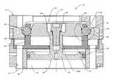
- FIG. 1is a cross-sectional view of the robotic tool changer of the present invention showing the piston of the tool changer in a locked position.
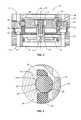
- FIG. 2is an enlarged view of the portion of the tool changer encircled in FIG. 1 and indicated by II.
- FIG. 3is a view similar to FIG. 1 , but showing the piston in a failsafe position.
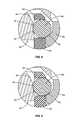
- FIG. 4is an enlarged view of the encircled portion of FIG. 3 indicated by IV.
- FIG. 5is a view similar to FIG. 1 , but showing the piston in an unlocked position.
- FIG. 6is an enlarged view of the encircled portion indicated by VI in FIG. 5 .
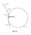
- FIG. 7Ais a schematic illustration showing the relationship between a portion of the piston and a rolling member as the piston moves between locked, failsafe, and unlocked positions.
- FIG. 7Bis a schematic illustration similar to FIG. 7A , but illustrating the contact area of the piston with respect to the longitudinal axis of the piston.
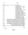
- FIG. 8is an enlarged view of a portion of the tool changer showing an alternate design for the piston and with the piston being shown in the locked position.
- FIG. 9is a view similar to FIG. 8 , but wherein the piston is disposed in the failsafe position.
- FIG. 10is a view similar to FIG. 8 wherein the piston is disposed in the unlocked position.
- FIG. 11Ais a schematic illustration of the piston of the alternative embodiment illustrating the movement of the piston with respect to a rolling member between locked, failsafe and unlocked positions.
- FIG. 11Bis a schematic illustration similar to FIG. 11A , but showing the contact area of the piston with respect to the longitudinal axis of the piston.
- FIG. 11Cis a schematic illustration of the force components that result as a rolling member moves from the locked position to the unlocked position with respect to the embodiment shown in FIGS. 8-11B .
- FIG. 12is a schematic illustration showing another alternate design for the contact area of the piston.
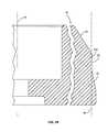
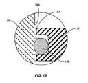
- FIG. 13is an enlarged view of the encircled area shown in FIG. 1 and denoted XII.
- Tool changer 10basically comprises a first unit and a second unit that are adapted to be coupled together.
- the first unitis indicated generally by the numeral 12 and is sometimes referred to as a master unit.
- the second unitis indicated generally by the numeral 14 and sometimes referred to as the tool unit.
- the first or master unit 12is typically connected to a robotic arm (not shown) while the second or tool unit 14 is typically connected to a particular tool.
- the respective tool units 14are coupled and decoupled to the first and master unit 12 .
- the robotic tool changer 10 disclosed hereinis similar in many respects to that disclosed in U.S. Pat. No. 5,211,501, which is expressly incorporated herein by reference.
- the robotic tool changer 10includes additional facilities for the provision of various services and utilities to the attached tool.
- relatively large electrical currentssuch as those utilized by a welding tool can be passed from an electrical source through the robotic system to the tool unit 14 .
- fluidssuch as pneumatics can be transferred through the master unit 12 to the tool unit 14 for use by a particular tool connected thereto.
- robotic tool changersinclude hydraulic fluid, cooling fluid, oil, and data transfer. Details of these services and utilities are not dealt with here in detail because such is not per se material to the present invention and because robotic tool changers of the general type shown herein are commercially known and available.
- the fluid chamber 15is cylindrical and includes a cylindrical wall 16 . Adjacent to the fluid chamber 15 is a structure that includes a horizontal member 18 that includes an annular ring 20 projecting therefrom. Horizontal member 18 forms one end of the fluid chamber 15 . Additionally, horizontal member 18 includes a central opening 18 A having an O-ring 18 B secured in an annular groove formed in the central opening. Formed in the annular ring 20 is a series of apertures or openings 22 . A rolling member 24 is generally held or disposed in each of the apertures or openings 22 . The area in and around the apertures 22 is sometimes referred to as a retention area because this area tends to at least partially retain the rolling members 24 that, as will be discussed subsequently herein, are utilized to lock the master unit 12 with the tool unit 14 .
- Piston 30is actuated back and forth in the fluid chamber 15 by a pressurized fluid source. In one embodiment, the piston 30 is pneumatically moved back and forth. Piston 30 includes a longitudinal axis indicated by the numeral 32 . Further, piston 30 includes a base 34 that is slidably contained within the fluid chamber 15 and forms a fluid tight seal with the chamber to prevent air or other fluid from bypassing the base. More particularly, the base 34 is provided with an O-ring 36 that seals against the cylindrical wall 16 of the fluid chamber 15 . Centered with respect to the base 34 is a stem 38 . Preferably the longitudinal axis 32 extends centrally through the stem 38 . As seen in FIG.
- stem 38extends through the opening 18 A formed in the horizontal member 18 .
- a generally cylindrical head indicated generally by the numeral 40Secured to the stem is a generally cylindrical head indicated generally by the numeral 40 .
- a screw 42extends through a portion of the head 40 and into a threaded cavity formed in the stem 18 . By tightening the screw 42 the head 40 of the piston 30 is coupled or connected to the base 34 of the piston.
- the outer perimeter of the head 40is configured to engage the rolling members 24 to effectuate locking the master unit 12 to the tool unit 14 .
- the outer perimeter of the headis particularly configured to cooperate with the locking members 24 to achieve both a locking and an unlocking function. Accordingly, the outer perimeter or outer area of the head 40 includes a contact area for contacting the rolling members 24 and for urging the rolling members 24 into a locked relationship with a portion of the tool unit 14 to be described subsequently herein.
- Locking surface 50is disposed at a taper or an angle with respect to the longitudinal axis 32 .
- the locking surface 50tapers generally upwardly and inwardly with respect to the longitudinal axis 32 .
- locking surface 50will engage the respective rolling members 24 and cause the rolling members 24 to engage a portion of the tool unit 14 and lock the master unit 12 and the tool unit 14 together.
- a contact surface 56that is sometimes referred to as an unlocking surface. As seen in FIGS. 2 , 4 and 6 , the contact surface 56 is tapered upwardly and inwardly towards the longitudinal axis 32 . Contact surface 56 provides two functions. As the piston 30 moves from the unlocked position to the locked position, the contact surface 56 surrounding the head 40 of the piston will contact the rolling members 24 and urge the same outwardly through the openings or apertures 22 formed in the annular ring 20 . Thus, surface 56 can be referred to as a contact surface. In addition, when the piston 30 assumes the unlocked position, the contact surface 56 will lie adjacent the rolling members 24 as shown in FIG. 6 .
- the rolling members 24are permitted to move to one side of the apertures 22 as shown in FIG. 6 .
- the contact surface 56 of the piston 30will prevent the rolling members 24 from falling from the apertures 22 .
- the position of the rolling members 24will permit the tool unit 14 to be decoupled from the master unit 12 without interference from the rolling members 24 .
- the surface 56is sometimes referred to as an unlocking surface.
- a failsafe surface 52Disposed adjacent the locking surface 50 is a failsafe surface 52 .
- a portion of the failsafe surface 52includes a generally cylindrical surface that extends generally parallel to the longitudinal axis 32 of the piston 30 .
- the failsafe surface 52also includes another portion which is referred to as a retarding surface 52 A.
- the failsafe surface 52extends generally between the locking surface 50 and the unlocking surface 56 .
- the cylindrical portion of the failsafe surface 52is disposed adjacent the locking surface 50 .
- the retarding portion 52 A of the locking surfaceis disposed adjacent the unlocking surface 56 .
- the purpose of the failsafe surface 52is to prevent the piston 30 from inadvertently or accidentally moving from the locked position shown in FIG. 1 to the unlocked position shown in FIGS. 5 and 6 .
- the rolling members 24will cause a force to be directed against the piston head 40 that will tend to drive the piston to the unlocked position in the event of an interruption in the actuating force that urges the piston to the locked position. If there is an inadvertent interruption in the actuating force acting on the piston 30 , then the piston will tend to move from the locked position in FIG. 1 to the failsafe position shown in FIGS. 3 and 4 .
- the cylindrical portion of the failsafe surface 52will, in many cases, aid in maintaining a coupled relationship between the master unit 12 and the tool unit 14 . However, the normal force directed against the rolling members 24 by the cylindrical portion of the failsafe surface 52 will produce no significant force component in the axial direction.
- the retarding surface 52 A that forms a part of the failsafe surface 52projects at least slightly outwardly from the cylindrical portion of the failsafe surface. The engagement of the retarding surface 52 A with the rolling members 24 will give rise to at least a slight resistance to further movement of the piston towards the unlocked position.
- the retarding surface 52 Aassumes the form of a ridge.
- the ridge that forms the retarding surface 52 Ais disposed generally between the cylindrical portion of the failsafe surface 52 and the contact or unlocking surface 56 .
- the dimensions of the ridgemay vary, it is contemplated that the ridge may project outwardly approximately 0.010 to 0.040 inches past the cylindrical portion of the failsafe surface.
- the relationship of the retarding surface 52 A in FIGS. 7A and 7Bthe ridge forming the retarding surface 52 A lies generally between the unlocking surface 56 and the cylindrical portion of the failsafe surface 52 .
- the master unit 12is adapted to be coupled to the tool unit.
- the tool unit 14is provided with a locking race 60 .
- the locking race 60which forms a part of the tool unit 14 , is designed to be inserted into the master unit 12 and to assume a position outwardly of and adjacent the rolling members 24 . See FIGS. 1-6 .
- Locking race 60includes a locking surface 62 .
- the piston 30is actuated and driven upwardly as viewed in FIG. 1 .
- the locking surface 50 of the piston 30will engage the rolling members 24 urging them outwardly through the apertures 22 of the annular ring 20 .
- the rolling members 24will engage the locking surface 62 that forms a part of the tool unit 14 and will urge the locking race 60 downwardly as viewed in FIG. 1 into the locked position shown therein.
- the failsafe surface 52In the failsafe position shown in FIGS. 4 and 7A , the failsafe surface 52 still engages the rolling members 24 .
- the failsafe surfaceaids in maintaining the coupled relationship between the master unit 12 and the tool unit 14 even though there is no significant opposing axial force created.
- the piston 30attempts to move past the ridge or retarding surface 52 A there will be an opposing axial force created by the engagement of the ridge with the rolling members 24 .
- Thiswill provide at least a slight and positive resistance that must be overcome in order for the piston 30 to move to the unlocked position. That is, as the rolling members attempt to clear the ridge, there will be at least a slight opposing axial force created.
- the locking race 60is free to move from the coupled position. More particularly, the unlocking surface 56 permits the rolling members 24 to assume the position shown in FIG. 6 , which in turn frees the locking race 60 , which of course means that the tool unit 14 can be decoupled from the master unit 12 .
- FIGS. 8-11Ca second embodiment is shown for the contact area of the head 40 of the piston 30 .
- the failsafe surface 52comprised a ridge disposed between the locking surface 50 and the contact or unlocking surface 56 .
- the failsafe surface 52forms a generally conical shape surface between the locking surface 50 and the contact or unlocking surface 56 . That is, as viewed in FIGS. 11A and 11B , the failsafe surface 52 extends upwardly and slightly outwardly to a point where the failsafe surface joins the contact or unlocking surface 56 . If the failsafe surface 52 is projected downwardly around the piston 30 , the projecting lines would form a cone. As seen in FIG.
- the angle of the conical surface 52is slight. As illustrated in FIG. 11B , the angle of the conical surface 52 with respect to a reference line RF, which is parallel to the longitudinal axis 32 of the piston, is preferably about 2° but may range from approximately 1° to 5°. Note that the angle of the conical surface 52 is represented by angle A ( FIG. 11B ) which is formed by reference line RF and construction line CL which is an extension of the conical or retarding surface 52 .
- FIG. 8the piston 30 assumes the locked position.
- the locking surface 50engages the rolling members 24 and urges the rolling members outwardly to where the rolling members engage the locking surface 62 of the locking race 60 of the tool unit 14 . This pulls the locking race 60 downwardly into a locked position.
- the piston 30will tend, as viewed in FIG. 9 , to move downwardly to where the rolling members 24 engage the failsafe surface 52 .
- the failsafe surface 52is conical or angled with respect to the longitudinal axis 32 of the piston, the rolling members 24 will be urged at least slightly outwardly as the piston 30 moves from the locked position to the unlocked position. That is, the conical or angled failsafe surface 52 generally prevents the piston from inadvertently moving from the locked position to the unlocked position. This is because the conical shape of the surface 52 forms a retarding surface which effectively retards the movement of the piston downwardly as viewed in FIG. 9 without an active unlocking force being applied to the piston.
- FIG. 11Cthere is a schematic illustration of the opposing axial force that is created or which results when the piston 30 moves from the locked position to the unlocked position.
- a normal force F 1is created. This force acts perpendicular to conical surface 52 and is directed generally horizontally and slightly upwardly as viewed in FIG. 11C .
- Force F 1includes a horizontal force component F 2 and a vertical or upwardly axial force component F 3 . It is the axial force component F 3 that must be overcome in order for the piston 30 to move from the locked position to the unlocked position.
- FIG. 12illustrates a third embodiment of the contact area of the piston head 40 .
- the failsafe surface 52includes two portions. First there is a generally cylindrical portion 52 B and a second conical portion 52 A. This design is similar to the embodiment shown in FIGS. 1-7B with the exception that the conical surface 52 B assumes the position of the ridge in the embodiment of FIGS. 1-7B .
- the rolling memberswill first engage the cylindrical portion 52 B of the failsafe surface, and thereafter will engage the conical or angled surface 52 B.
- the conical or angled surface 52 Bwill retard the movement of the piston 30 and prevent the piston 30 from inadvertently or accidentally moving past the conical or angled surface 52 B to the unlocked position.
- FIG. 13a portion of the stem 38 of the piston 30 is shown adjacent the horizontal member 18 .
- Stem 38is provided with a step 38 A.
- the dimension of the stepcan vary. In one embodiment it is contemplated that the step 38 A will project outwardly from the stem 38 approximately 0.005 to 0.010 inches.
- the step 38 Awill pass through the opening 18 A of the horizontal member 18 .
- the step 38 Awill engage the O-ring 18 B.
- the engagement of the step 38 A with the O-ring 18 Bwill at least slightly retard the further downward movement of the stem 38 .
- the engagement of the step 38 A with the O-ring 18 Bwill tend to compress or slightly deform the O-ring 18 B as the step 38 A passes the same.
- Step 38 Ais strategically placed on the stem 38 in order to protect against the inadvertent or accidental movement of the piston from the failsafe position to the unlocked position.
- the step 38 Awould lie immediately above the O-ring 18 B. If due to vibration or other external forces there was a tendency for the piston 30 to move to the unlocked position, step 38 A would engage the O-ring 18 B and at least slightly retard the further downward movement of the stem 38 . This would effectively hold the piston in the failsafe position.
- the step 38 Ais relatively small, its presence on a stem 38 would not inhibit or interfere with the normal up and down operation of the stem 38 as it and the piston moves between locked and unlocked positions.
Landscapes
- Engineering & Computer Science (AREA)
- Mechanical Engineering (AREA)
- Robotics (AREA)
- Actuator (AREA)
- Manipulator (AREA)
Abstract
Description
Claims (45)
Priority Applications (5)
| Application Number | Priority Date | Filing Date | Title |
|---|---|---|---|
| US11/374,706US8005570B2 (en) | 2006-03-14 | 2006-03-14 | Robotic tool changer |
| KR1020087023392AKR20090008192A (en) | 2006-03-14 | 2007-02-28 | Robotic tool changer |
| JP2009500545AJP2009530121A (en) | 2006-03-14 | 2007-02-28 | Robot tool changer |
| PCT/US2007/062940WO2007106662A2 (en) | 2006-03-14 | 2007-02-28 | Robotic tool changer |
| EP07778763.8AEP1993764B8 (en) | 2006-03-14 | 2007-02-28 | Robotic tool changer |
Applications Claiming Priority (1)
| Application Number | Priority Date | Filing Date | Title |
|---|---|---|---|
| US11/374,706US8005570B2 (en) | 2006-03-14 | 2006-03-14 | Robotic tool changer |
Publications (2)
| Publication Number | Publication Date |
|---|---|
| US20070235949A1 US20070235949A1 (en) | 2007-10-11 |
| US8005570B2true US8005570B2 (en) | 2011-08-23 |
Family
ID=38510147
Family Applications (1)
| Application Number | Title | Priority Date | Filing Date |
|---|---|---|---|
| US11/374,706Active2029-12-05US8005570B2 (en) | 2006-03-14 | 2006-03-14 | Robotic tool changer |
Country Status (5)
| Country | Link |
|---|---|
| US (1) | US8005570B2 (en) |
| EP (1) | EP1993764B8 (en) |
| JP (1) | JP2009530121A (en) |
| KR (1) | KR20090008192A (en) |
| WO (1) | WO2007106662A2 (en) |
Cited By (35)
| Publication number | Priority date | Publication date | Assignee | Title |
|---|---|---|---|---|
| US20070228670A1 (en)* | 2006-04-04 | 2007-10-04 | Ati Industrial Automation, Inc. | Electrically Actuated Robotic Tool Changer |
| US20080029976A1 (en)* | 2006-08-04 | 2008-02-07 | Ingersoll Machine Tools, Inc. | Clamping Apparatus And Method |
| US20090226249A1 (en)* | 2008-03-05 | 2009-09-10 | Hon Hai Precision Industry Co., Ltd. | Holding structure for robotic arm |
| US20090245993A1 (en)* | 2008-03-25 | 2009-10-01 | Hon Hai Precision Industry Co., Ltd. | Manipulator |
| US20100059943A1 (en)* | 2008-09-05 | 2010-03-11 | Ati Industrial Automation, Inc. | Manual Robotic Tool Changer with Rolling Members |
| US20100113236A1 (en)* | 2008-09-05 | 2010-05-06 | Ati Industrial Automation, Inc. | Manual Robotic Tool Changer Having Rapid Coupling Mechanism |
| US20150167719A1 (en)* | 2012-07-11 | 2015-06-18 | Almerino Canuto | Device for compensating offset in automatic locking systems |
| US20150258647A1 (en)* | 2014-03-11 | 2015-09-17 | Erowa Ag | Coupling Device For A Manipulator |
| US9151343B2 (en)* | 2013-03-14 | 2015-10-06 | Ati Industrial Automation, Inc. | Ball lock compensator for use with a robotic device |
| US20150375384A1 (en)* | 2014-06-26 | 2015-12-31 | Black & Decker Inc. | Tool Holder |
| WO2016028388A1 (en) | 2014-08-20 | 2016-02-25 | Ati Industrial Automation, Inc. | Robotic tool changer with tool stand decouple power supply |
| US20160201700A1 (en)* | 2015-01-09 | 2016-07-14 | Northrop Grumman Systems Corporation | Fluid-actuated fastening device |
| DE102016222287A1 (en) | 2015-11-12 | 2017-05-18 | Ati Industrial Automation, Inc. | SAFE ROBOT TOOL CHANGER |
| US20170144230A1 (en)* | 2015-11-24 | 2017-05-25 | GIMATIC S.r.l. | Tool changing device |
| US20170355049A1 (en)* | 2014-12-26 | 2017-12-14 | Nitta Corporation | Engagement component, female member, and tool replacement apparatus |
| US9981391B2 (en) | 2015-02-16 | 2018-05-29 | Norgren Automation Solutions, Llc | Quick disconnect apparatus for modular tooling |
| US10105855B2 (en) | 2015-02-16 | 2018-10-23 | Norgren Automation Solutions, Llc | Quick disconnect apparatus for modular tooling |
| US10357324B2 (en) | 2015-02-20 | 2019-07-23 | Stryker Corporation | Sterile barrier assembly, mounting system, and method for coupling surgical components |
| US10661449B2 (en) | 2014-08-20 | 2020-05-26 | Ati Industrial Automation, Inc. | Safe robotic tool changer |
| US10773817B1 (en) | 2018-03-08 | 2020-09-15 | Northrop Grumman Systems Corporation | Bi-directional flow ram air system for an aircraft |
| USD898879S1 (en) | 2017-05-01 | 2020-10-13 | Norgren Automation Solutions, Llc | Modular tooling coupler |
| RU2743389C1 (en)* | 2020-10-22 | 2021-02-17 | Федеральное государственное автономное образовательное учреждение высшего образования «Дальневосточный федеральный университет» (ДВФУ) | Detachable element automatic attachment unit |
| US11097390B2 (en) | 2014-08-20 | 2021-08-24 | Ati Industrial Automation, Inc. | Pneumatic safety interlock |
| DE102021112725A1 (en) | 2020-05-28 | 2021-12-02 | Ati Industrial Automation, Inc. | Pin, ring spring socket and high current connector for a robot device |
| DE102021114663A1 (en) | 2020-06-11 | 2021-12-16 | Ati Industrial Automation, Inc. | COUPLING MECHANISM FOR ROBOTIC TOOL CHANGERS WITH INCREASED TORSIONAL STIFFNESS AND REDUCED PLAY |
| US20220088798A1 (en)* | 2020-09-22 | 2022-03-24 | Ati Industrial Automation, Inc. | Robotic Tool Changer Coupling Mechanism with Increased Torsional Stiffness |
| US11806634B2 (en) | 2021-07-30 | 2023-11-07 | Tait Towers Manufacturing, LLC | Connection system for suspended loads for ride systems |
| US11931663B2 (en) | 2021-07-30 | 2024-03-19 | Tait Towers Manufacturing, LLC | Active damping system for suspended ride system |
| US11963733B2 (en) | 2021-12-01 | 2024-04-23 | Nuvasive Inc. | Connector assemblies for connecting a robotic arm with a medical end effector |
| US12082895B2 (en) | 2018-12-04 | 2024-09-10 | Mako Surgical Corp. | Robotic surgical system with a mounting assembly for attaching an end effector to a robotic arm |
| US12090638B2 (en) | 2020-08-25 | 2024-09-17 | Ati Industrial Automation, Inc. | Robotic tool changer having debris passages for channeling debris from the ball-locking mechanism |
| DE102024110103A1 (en) | 2023-04-17 | 2024-10-17 | Ati Industrial Automation, Inc. | MANUAL ROBOT TOOL CHANGER WITH A DECOUPLING FORCE THAT IS ESSENTIALLY OPPOSITE TO THE ACTUATING FORCE OF A SAFETY LOCK |
| US12256678B2 (en) | 2021-08-03 | 2025-03-25 | 4Ag Robotics Inc. | Automated mushroom harvesting system |
| US12377567B1 (en) | 2024-11-22 | 2025-08-05 | 4Ag Robotics Inc. | Mushroom trimming and sorting system |
| US12384026B1 (en) | 2024-02-08 | 2025-08-12 | 4Ag Robotics Inc. | Machine-learning-enabled tool changer for mushroom crop management system |
Families Citing this family (20)
| Publication number | Priority date | Publication date | Assignee | Title |
|---|---|---|---|---|
| US8601667B2 (en)* | 2006-04-04 | 2013-12-10 | Ati Industrial Automation, Inc. | Rotating coupling for robotic tool changer with actuation mechanism |
| US8209840B2 (en)* | 2006-04-04 | 2012-07-03 | Ati Industrial Automation, Inc. | Rotating coupling for robotic tool changer |
| US8500132B2 (en)* | 2006-04-04 | 2013-08-06 | Ati Industrial Automation, Inc. | Rotating coupling for robotic tool changer with one-way clutch and dual-button handle mechanism |
| CN101607398B (en)* | 2008-06-18 | 2012-06-20 | 鸿富锦精密工业(深圳)有限公司 | Clamp-replacing device |
| FI20100081A0 (en) | 2010-02-24 | 2010-02-24 | Raumaster Paper Oy | Grip changer equipment and roller storage |
| USD621859S1 (en)* | 2010-05-14 | 2010-08-17 | Tormach Llc | Tool changer fork |
| WO2014045390A1 (en)* | 2012-09-21 | 2014-03-27 | ビー・エル・オートテック株式会社 | Tool exchanger |
| JP2014217909A (en)* | 2013-05-07 | 2014-11-20 | ビー・エル・オートテック株式会社 | Master device for tool replacement device |
| TWI593525B (en)* | 2015-06-02 | 2017-08-01 | Hiwin Tech Corp | Mechanical replacement device and method for exchanging end effectors |
| JP6030718B1 (en) | 2015-07-03 | 2016-11-24 | 上銀科技股▲分▼有限公司 | Mechanical changer to replace end effector |
| US10286566B2 (en)* | 2015-10-06 | 2019-05-14 | Oceaneering International, Inc. | Manipulator end effector |
| JP6321852B1 (en)* | 2017-04-06 | 2018-05-09 | エスアールエンジニアリング株式会社 | Robot arm coupling device |
| US10335957B2 (en)* | 2017-04-25 | 2019-07-02 | Ati Industrial Automation, Inc. | Magnetically activated tool changer |
| CN107081781A (en)* | 2017-06-28 | 2017-08-22 | 深圳市恒拓高工业技术股份有限公司 | A kind of quick replacement device and its replacing options of industrial robot end-of-arm tooling |
| ES2975737T3 (en)* | 2017-12-14 | 2024-07-12 | Onrobot As | Gripping device |
| CN219027426U (en)* | 2020-03-23 | 2023-05-16 | 米沃奇电动工具公司 | Rotary hammer |
| WO2022004528A1 (en)* | 2020-07-01 | 2022-01-06 | ビー・エル・オートテック株式会社 | Tool changer |
| JP7608959B2 (en)* | 2021-04-22 | 2025-01-07 | Smc株式会社 | End effector exchange device |
| FR3122594B1 (en) | 2021-05-04 | 2023-05-26 | Commissariat Energie Atomique | Angular offset robotic arm tool holder interface |
| JP7655228B2 (en)* | 2022-01-07 | 2025-04-02 | Smc株式会社 | End effector exchange device |
Citations (19)
| Publication number | Priority date | Publication date | Assignee | Title |
|---|---|---|---|---|
| US4335500A (en)* | 1979-10-22 | 1982-06-22 | Toyoda Koki Kabushiki Kaisha | Tool storage magazine for machine tool |
| US4636135A (en)* | 1983-03-11 | 1987-01-13 | Societe Syspro | Tool-holder for industrial robot |
| US4679956A (en)* | 1986-01-08 | 1987-07-14 | General Motors Corporation | Quick disconnect device |
| US4696524A (en)* | 1986-03-03 | 1987-09-29 | Custom Tool & Mfg. Co. | Robot arm coupling apparatus |
| US4759686A (en)* | 1983-12-29 | 1988-07-26 | Rudi Kirst | Device for automatic interchange and coupling of grippers to robots or manipulating devices |
| US4815780A (en)* | 1987-03-30 | 1989-03-28 | Erowa Ag | Apparatus for detachably connecting a tool to a manipulating device |
| US4886467A (en)* | 1989-06-02 | 1989-12-12 | Chrysler Motors Corporation | Quick change tool holder |
| US4906123A (en)* | 1988-03-02 | 1990-03-06 | Wes-Tech, Inc. | Quick changecoupling system for robotic attachments |
| US5002500A (en)* | 1990-03-02 | 1991-03-26 | General Motors Corporation | Quick connect/disconnector for high amperage current |
| US5211501A (en)* | 1990-06-28 | 1993-05-18 | Bl Autotec, Ltd. | Robot arm coupling apparatus |
| US5522303A (en)* | 1993-03-03 | 1996-06-04 | Festo Kg Of Ruiter | Machine tool with locking mechanism |
| US5918870A (en)* | 1996-09-09 | 1999-07-06 | Stark; Emil | Clamping device for clamping a quick-clamp cylinder on a support plate for processing machines |
| US6375378B1 (en)* | 1998-11-05 | 2002-04-23 | Pascal Kabushiki Kaisha | Tool connecting device for robot hand |
| US6398279B1 (en)* | 1997-10-10 | 2002-06-04 | Kuka Schweissanlagen Gmbh | Interchangeable coupling |
| US20020067045A1 (en)* | 2000-12-06 | 2002-06-06 | Jean-Marie Blanchard | Assembly system based on a ball anchoring device |
| WO2003101673A2 (en) | 2002-05-29 | 2003-12-11 | Ati Industrial Automation | Robot arm coupling apparatus |
| US6752037B1 (en)* | 2000-07-06 | 2004-06-22 | Pascal Engineering Corporation | Tool connecting device for robot hand |
| US20060041328A1 (en)* | 2004-08-17 | 2006-02-23 | Delaware Capital Formation, Inc. | Method, system and program product for enabling rapid connection of automated tools to a device network |
| US20070228670A1 (en)* | 2006-04-04 | 2007-10-04 | Ati Industrial Automation, Inc. | Electrically Actuated Robotic Tool Changer |
- 2006
- 2006-03-14USUS11/374,706patent/US8005570B2/enactiveActive
- 2007
- 2007-02-28JPJP2009500545Apatent/JP2009530121A/enactivePending
- 2007-02-28WOPCT/US2007/062940patent/WO2007106662A2/enactiveApplication Filing
- 2007-02-28EPEP07778763.8Apatent/EP1993764B8/enactiveActive
- 2007-02-28KRKR1020087023392Apatent/KR20090008192A/ennot_activeCeased
Patent Citations (20)
| Publication number | Priority date | Publication date | Assignee | Title |
|---|---|---|---|---|
| US4335500A (en)* | 1979-10-22 | 1982-06-22 | Toyoda Koki Kabushiki Kaisha | Tool storage magazine for machine tool |
| US4636135A (en)* | 1983-03-11 | 1987-01-13 | Societe Syspro | Tool-holder for industrial robot |
| US4759686A (en)* | 1983-12-29 | 1988-07-26 | Rudi Kirst | Device for automatic interchange and coupling of grippers to robots or manipulating devices |
| US4679956A (en)* | 1986-01-08 | 1987-07-14 | General Motors Corporation | Quick disconnect device |
| US4696524A (en)* | 1986-03-03 | 1987-09-29 | Custom Tool & Mfg. Co. | Robot arm coupling apparatus |
| US4815780A (en)* | 1987-03-30 | 1989-03-28 | Erowa Ag | Apparatus for detachably connecting a tool to a manipulating device |
| US4906123A (en)* | 1988-03-02 | 1990-03-06 | Wes-Tech, Inc. | Quick changecoupling system for robotic attachments |
| US4886467A (en)* | 1989-06-02 | 1989-12-12 | Chrysler Motors Corporation | Quick change tool holder |
| US5002500A (en)* | 1990-03-02 | 1991-03-26 | General Motors Corporation | Quick connect/disconnector for high amperage current |
| US5211501A (en)* | 1990-06-28 | 1993-05-18 | Bl Autotec, Ltd. | Robot arm coupling apparatus |
| US5522303A (en)* | 1993-03-03 | 1996-06-04 | Festo Kg Of Ruiter | Machine tool with locking mechanism |
| US5918870A (en)* | 1996-09-09 | 1999-07-06 | Stark; Emil | Clamping device for clamping a quick-clamp cylinder on a support plate for processing machines |
| US6398279B1 (en)* | 1997-10-10 | 2002-06-04 | Kuka Schweissanlagen Gmbh | Interchangeable coupling |
| US6375378B1 (en)* | 1998-11-05 | 2002-04-23 | Pascal Kabushiki Kaisha | Tool connecting device for robot hand |
| US6752037B1 (en)* | 2000-07-06 | 2004-06-22 | Pascal Engineering Corporation | Tool connecting device for robot hand |
| US20020067045A1 (en)* | 2000-12-06 | 2002-06-06 | Jean-Marie Blanchard | Assembly system based on a ball anchoring device |
| WO2003101673A2 (en) | 2002-05-29 | 2003-12-11 | Ati Industrial Automation | Robot arm coupling apparatus |
| US7252453B1 (en)* | 2002-05-29 | 2007-08-07 | Ati Industrial Automation, Inc. | Robot arm coupling apparatus |
| US20060041328A1 (en)* | 2004-08-17 | 2006-02-23 | Delaware Capital Formation, Inc. | Method, system and program product for enabling rapid connection of automated tools to a device network |
| US20070228670A1 (en)* | 2006-04-04 | 2007-10-04 | Ati Industrial Automation, Inc. | Electrically Actuated Robotic Tool Changer |
Cited By (49)
| Publication number | Priority date | Publication date | Assignee | Title |
|---|---|---|---|---|
| US20070228670A1 (en)* | 2006-04-04 | 2007-10-04 | Ati Industrial Automation, Inc. | Electrically Actuated Robotic Tool Changer |
| US8132816B2 (en)* | 2006-04-04 | 2012-03-13 | Ati Industrial Automation, Inc. | Electrically Actuated Robotic Tool Changer |
| US20080029976A1 (en)* | 2006-08-04 | 2008-02-07 | Ingersoll Machine Tools, Inc. | Clamping Apparatus And Method |
| US8152173B2 (en)* | 2006-08-04 | 2012-04-10 | Ingersoll Machine Tools, Inc. | Clamping apparatus and method |
| US20090226249A1 (en)* | 2008-03-05 | 2009-09-10 | Hon Hai Precision Industry Co., Ltd. | Holding structure for robotic arm |
| US8267612B2 (en)* | 2008-03-05 | 2012-09-18 | Hon Hai Precision Industry Co., Ltd. | Holding structure for robotic arm |
| US8256751B2 (en)* | 2008-03-25 | 2012-09-04 | Hon Hai Precision Industry Co., Ltd. | Manipulator |
| US20090245993A1 (en)* | 2008-03-25 | 2009-10-01 | Hon Hai Precision Industry Co., Ltd. | Manipulator |
| US20100059943A1 (en)* | 2008-09-05 | 2010-03-11 | Ati Industrial Automation, Inc. | Manual Robotic Tool Changer with Rolling Members |
| US20100113236A1 (en)* | 2008-09-05 | 2010-05-06 | Ati Industrial Automation, Inc. | Manual Robotic Tool Changer Having Rapid Coupling Mechanism |
| US8533930B2 (en)* | 2008-09-05 | 2013-09-17 | Ati Industrial Automation, Inc. | Manual robotic tool changer having rapid coupling mechanism |
| US20150167719A1 (en)* | 2012-07-11 | 2015-06-18 | Almerino Canuto | Device for compensating offset in automatic locking systems |
| US9863456B2 (en)* | 2012-07-11 | 2018-01-09 | Almerino Canuto | Device for compensating offset in automatic locking systems |
| US9151343B2 (en)* | 2013-03-14 | 2015-10-06 | Ati Industrial Automation, Inc. | Ball lock compensator for use with a robotic device |
| US20150258647A1 (en)* | 2014-03-11 | 2015-09-17 | Erowa Ag | Coupling Device For A Manipulator |
| US9937595B2 (en)* | 2014-03-11 | 2018-04-10 | Erowa Ag | Coupling device for a manipulator |
| US9999968B2 (en)* | 2014-06-26 | 2018-06-19 | Black & Becker Inc. | Tool holder |
| US20150375384A1 (en)* | 2014-06-26 | 2015-12-31 | Black & Decker Inc. | Tool Holder |
| US11097390B2 (en) | 2014-08-20 | 2021-08-24 | Ati Industrial Automation, Inc. | Pneumatic safety interlock |
| WO2016028388A1 (en) | 2014-08-20 | 2016-02-25 | Ati Industrial Automation, Inc. | Robotic tool changer with tool stand decouple power supply |
| US10661449B2 (en) | 2014-08-20 | 2020-05-26 | Ati Industrial Automation, Inc. | Safe robotic tool changer |
| US10322455B2 (en)* | 2014-12-26 | 2019-06-18 | Nitta Corporation | Engagement component, female member, and tool replacement apparatus |
| US20170355049A1 (en)* | 2014-12-26 | 2017-12-14 | Nitta Corporation | Engagement component, female member, and tool replacement apparatus |
| US9677582B2 (en)* | 2015-01-09 | 2017-06-13 | Northrop Grumman Systems Corporation | Fluid-actuated fastening device |
| US20160201700A1 (en)* | 2015-01-09 | 2016-07-14 | Northrop Grumman Systems Corporation | Fluid-actuated fastening device |
| US10105855B2 (en) | 2015-02-16 | 2018-10-23 | Norgren Automation Solutions, Llc | Quick disconnect apparatus for modular tooling |
| US9981391B2 (en) | 2015-02-16 | 2018-05-29 | Norgren Automation Solutions, Llc | Quick disconnect apparatus for modular tooling |
| US10836050B2 (en) | 2015-02-16 | 2020-11-17 | Norgren Automation Solutions, Llc | Quick disconnect apparatus for modular tooling |
| US10357324B2 (en) | 2015-02-20 | 2019-07-23 | Stryker Corporation | Sterile barrier assembly, mounting system, and method for coupling surgical components |
| US11504203B2 (en) | 2015-02-20 | 2022-11-22 | Stryker Corporation | Sterile barrier assembly, mounting system, and method for coupling surgical components |
| DE102016222287A1 (en) | 2015-11-12 | 2017-05-18 | Ati Industrial Automation, Inc. | SAFE ROBOT TOOL CHANGER |
| US20170144230A1 (en)* | 2015-11-24 | 2017-05-25 | GIMATIC S.r.l. | Tool changing device |
| USD898879S1 (en) | 2017-05-01 | 2020-10-13 | Norgren Automation Solutions, Llc | Modular tooling coupler |
| US10773817B1 (en) | 2018-03-08 | 2020-09-15 | Northrop Grumman Systems Corporation | Bi-directional flow ram air system for an aircraft |
| US12082895B2 (en) | 2018-12-04 | 2024-09-10 | Mako Surgical Corp. | Robotic surgical system with a mounting assembly for attaching an end effector to a robotic arm |
| DE102021112725A1 (en) | 2020-05-28 | 2021-12-02 | Ati Industrial Automation, Inc. | Pin, ring spring socket and high current connector for a robot device |
| DE102021114663A1 (en) | 2020-06-11 | 2021-12-16 | Ati Industrial Automation, Inc. | COUPLING MECHANISM FOR ROBOTIC TOOL CHANGERS WITH INCREASED TORSIONAL STIFFNESS AND REDUCED PLAY |
| US11850733B2 (en) | 2020-06-11 | 2023-12-26 | Ati Industrial Automation, Inc. | Robotic tool changer coupling mechanism with increased torsional rigidity and reduced freeplay |
| US12090638B2 (en) | 2020-08-25 | 2024-09-17 | Ati Industrial Automation, Inc. | Robotic tool changer having debris passages for channeling debris from the ball-locking mechanism |
| US20220088798A1 (en)* | 2020-09-22 | 2022-03-24 | Ati Industrial Automation, Inc. | Robotic Tool Changer Coupling Mechanism with Increased Torsional Stiffness |
| US11691294B2 (en)* | 2020-09-22 | 2023-07-04 | Ati Industrial Automation, Inc. | Robotic tool changer coupling mechanism with increased torsional stiffness |
| RU2743389C1 (en)* | 2020-10-22 | 2021-02-17 | Федеральное государственное автономное образовательное учреждение высшего образования «Дальневосточный федеральный университет» (ДВФУ) | Detachable element automatic attachment unit |
| US11806634B2 (en) | 2021-07-30 | 2023-11-07 | Tait Towers Manufacturing, LLC | Connection system for suspended loads for ride systems |
| US11931663B2 (en) | 2021-07-30 | 2024-03-19 | Tait Towers Manufacturing, LLC | Active damping system for suspended ride system |
| US12256678B2 (en) | 2021-08-03 | 2025-03-25 | 4Ag Robotics Inc. | Automated mushroom harvesting system |
| US11963733B2 (en) | 2021-12-01 | 2024-04-23 | Nuvasive Inc. | Connector assemblies for connecting a robotic arm with a medical end effector |
| DE102024110103A1 (en) | 2023-04-17 | 2024-10-17 | Ati Industrial Automation, Inc. | MANUAL ROBOT TOOL CHANGER WITH A DECOUPLING FORCE THAT IS ESSENTIALLY OPPOSITE TO THE ACTUATING FORCE OF A SAFETY LOCK |
| US12384026B1 (en) | 2024-02-08 | 2025-08-12 | 4Ag Robotics Inc. | Machine-learning-enabled tool changer for mushroom crop management system |
| US12377567B1 (en) | 2024-11-22 | 2025-08-05 | 4Ag Robotics Inc. | Mushroom trimming and sorting system |
Also Published As
| Publication number | Publication date |
|---|---|
| WO2007106662A2 (en) | 2007-09-20 |
| EP1993764A4 (en) | 2009-04-15 |
| WO2007106662A3 (en) | 2008-05-02 |
| JP2009530121A (en) | 2009-08-27 |
| EP1993764A2 (en) | 2008-11-26 |
| EP1993764B1 (en) | 2016-10-26 |
| EP1993764B8 (en) | 2017-01-04 |
| KR20090008192A (en) | 2009-01-21 |
| US20070235949A1 (en) | 2007-10-11 |
Similar Documents
| Publication | Publication Date | Title |
|---|---|---|
| US8005570B2 (en) | Robotic tool changer | |
| US10335957B2 (en) | Magnetically activated tool changer | |
| US7819392B2 (en) | Positioning and clamping device and positioning device | |
| US7168695B2 (en) | Positioning device | |
| JP4954899B2 (en) | Positioning device and positioning system | |
| US8585031B2 (en) | Quick action clamping cylinder with a simplified structure | |
| EP0982519A1 (en) | Stop valve | |
| US9484242B2 (en) | Fluid pressure cylinder | |
| JP2009506902A (en) | Positioning and clamping device for tools or workpieces | |
| US20070158891A1 (en) | Quick action clamping cylinder with a simplified structure | |
| TW201206617A (en) | Clamp device | |
| JP2012066373A (en) | Clamp device | |
| KR102580656B1 (en) | clamp device | |
| US20210095715A1 (en) | Joint assembly for motion simulator | |
| JP2001087965A (en) | Coupling system for connection of supply line positioned on machine for various media including electric connections between machine tool and work carrier coupled therewith | |
| KR20250041163A (en) | Absentee Exchange Device | |
| EP0636450B1 (en) | Clamping apparatus | |
| US20110030805A1 (en) | Blowout preventer with lock | |
| JP4900714B2 (en) | Fusible stopper | |
| US20080190282A1 (en) | Lockable Working Cylinder | |
| JP2003311572A (en) | Automatic positioning device | |
| US8042575B2 (en) | Spring energized plug | |
| WO2019176712A1 (en) | Hydraulic cylinder equipped with detection mechanism | |
| JPH02224933A (en) | Tightening device for bolt | |
| JP2005224929A (en) | Aligning device and positioning system equipped with the device |
Legal Events
| Date | Code | Title | Description |
|---|---|---|---|
| AS | Assignment | Owner name:ATI INDUSTRIAL AUTOMATION, NORTH CAROLINA Free format text:ASSIGNMENT OF ASSIGNORS INTEREST;ASSIGNORS:GLODEN, MICHAEL L.;ODHAM, LEONARD AARON;BORDEAUX, MARK D.;REEL/FRAME:017641/0726 Effective date:20060313 | |
| STCF | Information on status: patent grant | Free format text:PATENTED CASE | |
| FPAY | Fee payment | Year of fee payment:4 | |
| FEPP | Fee payment procedure | Free format text:7.5 YR SURCHARGE - LATE PMT W/IN 6 MO, SMALL ENTITY (ORIGINAL EVENT CODE: M2555); ENTITY STATUS OF PATENT OWNER: SMALL ENTITY | |
| MAFP | Maintenance fee payment | Free format text:PAYMENT OF MAINTENANCE FEE, 8TH YR, SMALL ENTITY (ORIGINAL EVENT CODE: M2552); ENTITY STATUS OF PATENT OWNER: SMALL ENTITY Year of fee payment:8 | |
| AS | Assignment | Owner name:BANK OF AMERICA, N.A., NORTH CAROLINA Free format text:SECURITY INTEREST;ASSIGNOR:ATI INDUSTRIAL AUTOMATION, INC.;REEL/FRAME:057727/0904 Effective date:20210930 | |
| FEPP | Fee payment procedure | Free format text:ENTITY STATUS SET TO UNDISCOUNTED (ORIGINAL EVENT CODE: BIG.); ENTITY STATUS OF PATENT OWNER: LARGE ENTITY | |
| MAFP | Maintenance fee payment | Free format text:PAYMENT OF MAINTENANCE FEE, 12TH YEAR, LARGE ENTITY (ORIGINAL EVENT CODE: M1553); ENTITY STATUS OF PATENT OWNER: LARGE ENTITY Year of fee payment:12 |