US8005529B2 - Systems and methods for internal tissue penetration - Google Patents
Systems and methods for internal tissue penetrationDownload PDFInfo
- Publication number
- US8005529B2 US8005529B2US12/749,234US74923410AUS8005529B2US 8005529 B2US8005529 B2US 8005529B2US 74923410 AUS74923410 AUS 74923410AUS 8005529 B2US8005529 B2US 8005529B2
- Authority
- US
- United States
- Prior art keywords
- inner core
- distal end
- imager
- tissue
- body tissue
- Prior art date
- Legal status (The legal status is an assumption and is not a legal conclusion. Google has not performed a legal analysis and makes no representation as to the accuracy of the status listed.)
- Expired - Lifetime
Links
- 230000035515penetrationEffects0.000titleclaimsdescription70
- 238000000034methodMethods0.000titledescription45
- 238000003384imaging methodMethods0.000claimsabstractdescription54
- 210000001519tissueAnatomy0.000description131
- 239000012528membraneSubstances0.000description21
- 230000008569processEffects0.000description18
- 210000001175cerebrospinal fluidAnatomy0.000description16
- 239000012530fluidSubstances0.000description14
- 210000000211third ventricleAnatomy0.000description13
- 238000005345coagulationMethods0.000description11
- 230000015271coagulationEffects0.000description11
- 230000001419dependent effectEffects0.000description9
- 210000001367arteryAnatomy0.000description6
- 210000004204blood vesselAnatomy0.000description6
- 208000003906hydrocephalusDiseases0.000description6
- 230000000149penetrating effectEffects0.000description6
- 210000004705lumbosacral regionAnatomy0.000description5
- 208000032843HemorrhageDiseases0.000description4
- 238000002399angioplastyMethods0.000description4
- 230000008901benefitEffects0.000description4
- 208000034158bleedingDiseases0.000description4
- 230000000740bleeding effectEffects0.000description4
- 210000003169central nervous systemAnatomy0.000description4
- 238000010586diagramMethods0.000description4
- 206010028980NeoplasmDiseases0.000description3
- 210000004556brainAnatomy0.000description3
- 210000004289cerebral ventricleAnatomy0.000description3
- 230000007423decreaseEffects0.000description3
- 230000003247decreasing effectEffects0.000description3
- 230000000694effectsEffects0.000description3
- 238000003780insertionMethods0.000description3
- 230000037431insertionEffects0.000description3
- 239000000463materialSubstances0.000description3
- 238000012014optical coherence tomographyMethods0.000description3
- 238000002281optical coherence-domain reflectometryMethods0.000description3
- 210000000278spinal cordAnatomy0.000description3
- 230000002463transducing effectEffects0.000description3
- FAPWRFPIFSIZLT-UHFFFAOYSA-MSodium chlorideChemical compound[Na+].[Cl-]FAPWRFPIFSIZLT-UHFFFAOYSA-M0.000description2
- 239000008280bloodSubstances0.000description2
- 210000004369bloodAnatomy0.000description2
- 210000001124body fluidAnatomy0.000description2
- 238000002591computed tomographyMethods0.000description2
- 230000002596correlated effectEffects0.000description2
- 239000007943implantSubstances0.000description2
- 239000007769metal materialSubstances0.000description2
- 201000011107obstructive hydrocephalusDiseases0.000description2
- 230000003287optical effectEffects0.000description2
- 238000012634optical imagingMethods0.000description2
- 239000011780sodium chlorideSubstances0.000description2
- 210000002330subarachnoid spaceAnatomy0.000description2
- 238000001356surgical procedureMethods0.000description2
- 200000000007Arterial diseaseDiseases0.000description1
- 201000001320AtherosclerosisDiseases0.000description1
- 238000002679ablationMethods0.000description1
- 238000001574biopsyMethods0.000description1
- 230000017531blood circulationEffects0.000description1
- 239000010839body fluidSubstances0.000description1
- 210000000988bone and boneAnatomy0.000description1
- 210000000133brain stemAnatomy0.000description1
- 230000004087circulationEffects0.000description1
- 201000003083communicating hydrocephalusDiseases0.000description1
- 238000004891communicationMethods0.000description1
- 238000007796conventional methodMethods0.000description1
- 210000004351coronary vesselAnatomy0.000description1
- 230000000875corresponding effectEffects0.000description1
- 210000003792cranial nerveAnatomy0.000description1
- 238000000315cryotherapyMethods0.000description1
- 238000013461designMethods0.000description1
- 238000003745diagnosisMethods0.000description1
- 238000002059diagnostic imagingMethods0.000description1
- 238000005553drillingMethods0.000description1
- 239000003814drugSubstances0.000description1
- 238000012377drug deliveryMethods0.000description1
- 238000002566electrocorticographyMethods0.000description1
- 238000002594fluoroscopyMethods0.000description1
- 230000036541healthEffects0.000description1
- 230000002631hypothermal effectEffects0.000description1
- 238000002513implantationMethods0.000description1
- 238000005259measurementMethods0.000description1
- 238000000968medical method and processMethods0.000description1
- 238000012986modificationMethods0.000description1
- 230000004048modificationEffects0.000description1
- 230000000877morphologic effectEffects0.000description1
- 210000000056organAnatomy0.000description1
- 230000037361pathwayEffects0.000description1
- 230000002028prematureEffects0.000description1
- 238000012545processingMethods0.000description1
- 239000012857radioactive materialSubstances0.000description1
- 239000000941radioactive substanceSubstances0.000description1
- 230000004044responseEffects0.000description1
- 238000000926separation methodMethods0.000description1
- 210000004872soft tissueAnatomy0.000description1
- 210000001032spinal nerveAnatomy0.000description1
- 230000008961swellingEffects0.000description1
- 229940124597therapeutic agentDrugs0.000description1
- 238000003325tomographyMethods0.000description1
- 238000002604ultrasonographyMethods0.000description1
Images


Classifications
- A—HUMAN NECESSITIES
- A61—MEDICAL OR VETERINARY SCIENCE; HYGIENE
- A61B—DIAGNOSIS; SURGERY; IDENTIFICATION
- A61B1/00—Instruments for performing medical examinations of the interior of cavities or tubes of the body by visual or photographical inspection, e.g. endoscopes; Illuminating arrangements therefor
- A61B1/00064—Constructional details of the endoscope body
- A61B1/00071—Insertion part of the endoscope body
- A61B1/0008—Insertion part of the endoscope body characterised by distal tip features
- A61B1/00087—Tools
- A—HUMAN NECESSITIES
- A61—MEDICAL OR VETERINARY SCIENCE; HYGIENE
- A61B—DIAGNOSIS; SURGERY; IDENTIFICATION
- A61B1/00—Instruments for performing medical examinations of the interior of cavities or tubes of the body by visual or photographical inspection, e.g. endoscopes; Illuminating arrangements therefor
- A61B1/00064—Constructional details of the endoscope body
- A61B1/00071—Insertion part of the endoscope body
- A61B1/0008—Insertion part of the endoscope body characterised by distal tip features
- A61B1/00082—Balloons
- A—HUMAN NECESSITIES
- A61—MEDICAL OR VETERINARY SCIENCE; HYGIENE
- A61B—DIAGNOSIS; SURGERY; IDENTIFICATION
- A61B1/00—Instruments for performing medical examinations of the interior of cavities or tubes of the body by visual or photographical inspection, e.g. endoscopes; Illuminating arrangements therefor
- A61B1/00131—Accessories for endoscopes
- A61B1/00135—Oversleeves mounted on the endoscope prior to insertion
- A—HUMAN NECESSITIES
- A61—MEDICAL OR VETERINARY SCIENCE; HYGIENE
- A61B—DIAGNOSIS; SURGERY; IDENTIFICATION
- A61B1/00—Instruments for performing medical examinations of the interior of cavities or tubes of the body by visual or photographical inspection, e.g. endoscopes; Illuminating arrangements therefor
- A61B1/313—Instruments for performing medical examinations of the interior of cavities or tubes of the body by visual or photographical inspection, e.g. endoscopes; Illuminating arrangements therefor for introducing through surgical openings, e.g. laparoscopes
- A61B1/3132—Instruments for performing medical examinations of the interior of cavities or tubes of the body by visual or photographical inspection, e.g. endoscopes; Illuminating arrangements therefor for introducing through surgical openings, e.g. laparoscopes for laparoscopy
- A—HUMAN NECESSITIES
- A61—MEDICAL OR VETERINARY SCIENCE; HYGIENE
- A61B—DIAGNOSIS; SURGERY; IDENTIFICATION
- A61B17/00—Surgical instruments, devices or methods
- A61B17/32—Surgical cutting instruments
- A61B17/320016—Endoscopic cutting instruments, e.g. arthroscopes, resectoscopes
- A61B17/32002—Endoscopic cutting instruments, e.g. arthroscopes, resectoscopes with continuously rotating, oscillating or reciprocating cutting instruments
- A—HUMAN NECESSITIES
- A61—MEDICAL OR VETERINARY SCIENCE; HYGIENE
- A61B—DIAGNOSIS; SURGERY; IDENTIFICATION
- A61B5/00—Measuring for diagnostic purposes; Identification of persons
- A61B5/0059—Measuring for diagnostic purposes; Identification of persons using light, e.g. diagnosis by transillumination, diascopy, fluorescence
- A61B5/0082—Measuring for diagnostic purposes; Identification of persons using light, e.g. diagnosis by transillumination, diascopy, fluorescence adapted for particular medical purposes
- A61B5/0084—Measuring for diagnostic purposes; Identification of persons using light, e.g. diagnosis by transillumination, diascopy, fluorescence adapted for particular medical purposes for introduction into the body, e.g. by catheters
- A—HUMAN NECESSITIES
- A61—MEDICAL OR VETERINARY SCIENCE; HYGIENE
- A61B—DIAGNOSIS; SURGERY; IDENTIFICATION
- A61B17/00—Surgical instruments, devices or methods
- A61B17/34—Trocars; Puncturing needles
- A61B17/3478—Endoscopic needles, e.g. for infusion
- A—HUMAN NECESSITIES
- A61—MEDICAL OR VETERINARY SCIENCE; HYGIENE
- A61B—DIAGNOSIS; SURGERY; IDENTIFICATION
- A61B17/00—Surgical instruments, devices or methods
- A61B17/00234—Surgical instruments, devices or methods for minimally invasive surgery
- A61B2017/00238—Type of minimally invasive operation
- A61B2017/00243—Type of minimally invasive operation cardiac
- A61B2017/00247—Making holes in the wall of the heart, e.g. laser Myocardial revascularization
- A—HUMAN NECESSITIES
- A61—MEDICAL OR VETERINARY SCIENCE; HYGIENE
- A61B—DIAGNOSIS; SURGERY; IDENTIFICATION
- A61B17/00—Surgical instruments, devices or methods
- A61B17/22—Implements for squeezing-off ulcers or the like on inner organs of the body; Implements for scraping-out cavities of body organs, e.g. bones; for invasive removal or destruction of calculus using mechanical vibrations; for removing obstructions in blood vessels, not otherwise provided for
- A61B2017/22072—Implements for squeezing-off ulcers or the like on inner organs of the body; Implements for scraping-out cavities of body organs, e.g. bones; for invasive removal or destruction of calculus using mechanical vibrations; for removing obstructions in blood vessels, not otherwise provided for with an instrument channel, e.g. for replacing one instrument by the other
- A61B2017/22074—Implements for squeezing-off ulcers or the like on inner organs of the body; Implements for scraping-out cavities of body organs, e.g. bones; for invasive removal or destruction of calculus using mechanical vibrations; for removing obstructions in blood vessels, not otherwise provided for with an instrument channel, e.g. for replacing one instrument by the other the instrument being only slidable in a channel, e.g. advancing optical fibre through a channel
- A61B2017/22075—Implements for squeezing-off ulcers or the like on inner organs of the body; Implements for scraping-out cavities of body organs, e.g. bones; for invasive removal or destruction of calculus using mechanical vibrations; for removing obstructions in blood vessels, not otherwise provided for with an instrument channel, e.g. for replacing one instrument by the other the instrument being only slidable in a channel, e.g. advancing optical fibre through a channel with motorized advancing or retracting means
- A—HUMAN NECESSITIES
- A61—MEDICAL OR VETERINARY SCIENCE; HYGIENE
- A61B—DIAGNOSIS; SURGERY; IDENTIFICATION
- A61B17/00—Surgical instruments, devices or methods
- A61B17/22—Implements for squeezing-off ulcers or the like on inner organs of the body; Implements for scraping-out cavities of body organs, e.g. bones; for invasive removal or destruction of calculus using mechanical vibrations; for removing obstructions in blood vessels, not otherwise provided for
- A61B2017/22072—Implements for squeezing-off ulcers or the like on inner organs of the body; Implements for scraping-out cavities of body organs, e.g. bones; for invasive removal or destruction of calculus using mechanical vibrations; for removing obstructions in blood vessels, not otherwise provided for with an instrument channel, e.g. for replacing one instrument by the other
- A61B2017/22074—Implements for squeezing-off ulcers or the like on inner organs of the body; Implements for scraping-out cavities of body organs, e.g. bones; for invasive removal or destruction of calculus using mechanical vibrations; for removing obstructions in blood vessels, not otherwise provided for with an instrument channel, e.g. for replacing one instrument by the other the instrument being only slidable in a channel, e.g. advancing optical fibre through a channel
- A61B2017/22077—Implements for squeezing-off ulcers or the like on inner organs of the body; Implements for scraping-out cavities of body organs, e.g. bones; for invasive removal or destruction of calculus using mechanical vibrations; for removing obstructions in blood vessels, not otherwise provided for with an instrument channel, e.g. for replacing one instrument by the other the instrument being only slidable in a channel, e.g. advancing optical fibre through a channel with a part piercing the tissue
- A—HUMAN NECESSITIES
- A61—MEDICAL OR VETERINARY SCIENCE; HYGIENE
- A61B—DIAGNOSIS; SURGERY; IDENTIFICATION
- A61B17/00—Surgical instruments, devices or methods
- A61B17/22—Implements for squeezing-off ulcers or the like on inner organs of the body; Implements for scraping-out cavities of body organs, e.g. bones; for invasive removal or destruction of calculus using mechanical vibrations; for removing obstructions in blood vessels, not otherwise provided for
- A61B2017/22072—Implements for squeezing-off ulcers or the like on inner organs of the body; Implements for scraping-out cavities of body organs, e.g. bones; for invasive removal or destruction of calculus using mechanical vibrations; for removing obstructions in blood vessels, not otherwise provided for with an instrument channel, e.g. for replacing one instrument by the other
- A61B2017/22078—Implements for squeezing-off ulcers or the like on inner organs of the body; Implements for scraping-out cavities of body organs, e.g. bones; for invasive removal or destruction of calculus using mechanical vibrations; for removing obstructions in blood vessels, not otherwise provided for with an instrument channel, e.g. for replacing one instrument by the other for rotating the instrument within a channel, e.g. an optical fibre
- A—HUMAN NECESSITIES
- A61—MEDICAL OR VETERINARY SCIENCE; HYGIENE
- A61B—DIAGNOSIS; SURGERY; IDENTIFICATION
- A61B17/00—Surgical instruments, devices or methods
- A61B17/32—Surgical cutting instruments
- A61B2017/320004—Surgical cutting instruments abrasive
- A—HUMAN NECESSITIES
- A61—MEDICAL OR VETERINARY SCIENCE; HYGIENE
- A61B—DIAGNOSIS; SURGERY; IDENTIFICATION
- A61B18/00—Surgical instruments, devices or methods for transferring non-mechanical forms of energy to or from the body
- A61B2018/00315—Surgical instruments, devices or methods for transferring non-mechanical forms of energy to or from the body for treatment of particular body parts
- A61B2018/00345—Vascular system
- A61B2018/00351—Heart
- A61B2018/00392—Transmyocardial revascularisation
- A—HUMAN NECESSITIES
- A61—MEDICAL OR VETERINARY SCIENCE; HYGIENE
- A61B—DIAGNOSIS; SURGERY; IDENTIFICATION
- A61B90/00—Instruments, implements or accessories specially adapted for surgery or diagnosis and not covered by any of the groups A61B1/00 - A61B50/00, e.g. for luxation treatment or for protecting wound edges
- A61B90/36—Image-producing devices or illumination devices not otherwise provided for
- A61B90/37—Surgical systems with images on a monitor during operation
- A61B2090/378—Surgical systems with images on a monitor during operation using ultrasound
- A61B2090/3782—Surgical systems with images on a monitor during operation using ultrasound transmitter or receiver in catheter or minimal invasive instrument
- A—HUMAN NECESSITIES
- A61—MEDICAL OR VETERINARY SCIENCE; HYGIENE
- A61B—DIAGNOSIS; SURGERY; IDENTIFICATION
- A61B5/00—Measuring for diagnostic purposes; Identification of persons
- A61B5/0059—Measuring for diagnostic purposes; Identification of persons using light, e.g. diagnosis by transillumination, diascopy, fluorescence
- A61B5/0062—Arrangements for scanning
- A61B5/0066—Optical coherence imaging
- A—HUMAN NECESSITIES
- A61—MEDICAL OR VETERINARY SCIENCE; HYGIENE
- A61B—DIAGNOSIS; SURGERY; IDENTIFICATION
- A61B8/00—Diagnosis using ultrasonic, sonic or infrasonic waves
- A61B8/12—Diagnosis using ultrasonic, sonic or infrasonic waves in body cavities or body tracts, e.g. by using catheters
- A—HUMAN NECESSITIES
- A61—MEDICAL OR VETERINARY SCIENCE; HYGIENE
- A61B—DIAGNOSIS; SURGERY; IDENTIFICATION
- A61B8/00—Diagnosis using ultrasonic, sonic or infrasonic waves
- A61B8/44—Constructional features of the ultrasonic, sonic or infrasonic diagnostic device
- A61B8/4444—Constructional features of the ultrasonic, sonic or infrasonic diagnostic device related to the probe
- A61B8/445—Details of catheter construction
Definitions
- the field of the inventionrelates generally to medical devices, and more particularly to a medical devices for penetrating a body tissue of a living being.
- Cathetersare tools commonly employed to help diagnose and treat medical conditions by allowing access to remote locations within a living body.
- a wide range of medical procedurescan be performed with a catheter, such as imaging, angioplasty and the release of therapeutic agents into the body.
- Cathetersprovide particular advantages when used to gain access to regions of the body otherwise reachable only with invasive surgery.
- Cathetersare most often used in diagnosing and treating atherosclerosis and other arterial diseases with procedures such as angioplasty.
- angioplastya balloon located on a catheter is placed within a constricted artery and inflated so as to break apart occlusive plaque and restore normal blood flow to the artery.
- the catheterIn order to place the balloon within the constricted artery, the catheter is typically advanced through various body lumens, such as arteries and blood vessels within the circulatory system. By this nature, navigation through these lumens is generally unrestricted.
- cathetersare frequently adopted to navigate to other regions of the body, outside the circulatory system. In these cases, access can be restricted by one or more body tissues. In many cases the only way to reach the desired location is to advance the catheter through the obstructing tissue.
- Various systems and methodologieshave been developed to penetrate the obstracting tissue. For instance, some systems rely on piercing instrumets such as a needle, located within the catheter, to pierce the tissue and create an opening through which the catheter can be advanced. Other systems rely on a drilling instrument, where an actual drill bit is used to penetrate the material. These systems are very inaccurate and can easily damage other tissues within the body.
- these systemstypically run the risk of “overshoot,” which occurs when the various instrument advances further than intended, either too far into the body tissue or entirely through the body tissue and into a second tissue.
- These instrumentsalso run the risk of damaging body tissue by mere incidental contact with another tissue.
- these systemsare often encumbered by the penetrating instrument, which must be incorporated into the catheter along with the other medical or imaging devices already in place.
- these instrumentsare effectively blind when penetrating a tissue, in which case penetration can occur directly into a blood vessel or other vital organ resulting in a serious health risk to the patient.
- An improved medical devicesuch as a catheter preferably includes an inner core and an imager that is extendable from an elongated tubular member and configured to penetrate body tissue within a living body.
- a distal end of the elongated memberis advanced into proximity with a body tissue.
- an inner core within the elongated memberis rotated radially around a longitudinal axis of the member.
- the tissueis then imaged with an imager located at the distal end of the inner core to locate an optimum penetration region.
- the distal end of the inner coreis advanced past the distal end of the elongated member such that the core is placed into contact with the tissue at the optimum region.
- the tissueis penetrated by the rotation of the imager and creates an opening.
- the imageris imaging to provide a more accurate penetration of the tissue and to ensure that the inner core remains placed over region.
- the improved medical deviceincludes an elongated tubular member having a distal end and configured to slideably receive an inner core.
- the distal endis further configured to allow the inner core to advance outside the elongated member.
- the inner corehas a distal end and is configured to rotate radially around a longitudinal axis of the elongated member.
- the devicefurther includes an imager located at the distal end of the inner core, wherein the imager is configured to image a body tissue and output an image signal to an imaging system communicatively coupled with the imager.
- the imaging systemis configured to generate an image of the body tissue from the image signal of the imager when the imager is rotated and placed into contact with the body tissue such that the imager penetrates the body tissue.
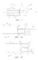
- FIG. 1is a schematic diagram depicting an example embodiment of a medical system.
- FIG. 2Ais a perspective view of an example embodiment of a catheter within the medical system.
- FIG. 2Bis a perspective view of another example embodiment of a catheter within the medical system.
- FIGS. 3A-Gare perspective views of additional example embodiments of a catheter within the medical system.
- FIG. 4is a flow diagram of an example embodiment of penetration process.
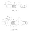
- FIGS. 5A-Iare perspective views of example embodiments of a transducer within the medical system.
- FIG. 6is a perspective view of another example embodiment of a catheter within the medical system.
- FIGS. 7A-Bare perspective views of additional example embodiments of a catheter within the medical system.
- FIGS. 8A-Bare perspective views of additional example embodiments of a catheter within the medical system.
- FIG. 9is a perspective view of a central nervous system in which an example embodiment of the medical system can be implemented.
- FIG. 10a perspective view of a central nervous system in which an example embodiment of the medical system can be implemented.
- FIG. 11is a flow diagram of another example embodiment of penetration process.
- a medical devicesuch as catheter
- a living bodyis inserted into a living body and used to penetrate the body tissue.
- a catheteris inserted into a living body and used to penetrate the body tissue.
- An inner core within the catheteris rotated and placed into direct contact with a body tissue and penetrates the tissue, creating an opening through which the catheter can be passed.
- the inner coreincludes an imager configured to image the body tissue in order to determine an optimum location to penetrate and to image the tissue during penetration.
- the catheteris connected to an imaging system where the image can be displayed and used in medical diagnosis and treatment.
- FIG. 1depicts medical system 100 , which is a preferred embodiment of the systems and methods described herein.
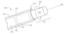
- medical device 102which is preferably a catheter, elongated tubular member 104 and inner core 106 , which includes imager 108 .
- Catheter 102is insertable into a living body and can be advanced through a body lumen such as a blood vessel, artery, or a body canal, while at the same time imaging that body lumen or canal.
- Catheter 102includes distal end 103 and proximal end 107 .
- imaging system 112 and control system 114is also depicted in medical system 100 .
- Medical system 100is configured to enable a user to image the interior of the body in order to navigate and advance catheter 102 throughout the body.
- Imaging system 112includes the imaging software and hardware that is used to view the interior image of the body.
- Control system 114controls the rate of rotation of inner core 106 and can also be configured to control the rate of advancement of elongated member 104 , inner core 106 or both.
- FIG. 2Adepicts an example embodiment of distal end 103 of catheter 102 including elongated member 104 and inner core 106 .
- Elongated member 104is preferably composed of a flexible material and is shaped in a tubular manner, hollowed in the center to slideably receive inner core 106 .
- inner core 106is configured to move axially along center longitudinal axis 208 of elongated member 104 and also to rotate radially around axis 208 .
- Inner core 106includes drive shaft 204 and a signal line (not shown). Opening 110 allows inner core 106 to slide outside of distal end 105 of elongated member 104 . Opening 110 can be open or collapsible, depending on the needs of the application.
- Control system 114can include a check valve to add more fluid 209 if needed.
- a collapsible opening 110may be desired in applications where the escape of catheter fluid 209 or entry of body fluids into catheter 102 is undesirable.
- Imager 108is preferably located at the distal end of inner core 106 so that when inner core 106 is advanced outside of elongated member 104 , imager 108 is placed into contact with a body tissue. When inner core 106 is rotating and in contact with the body tissue, imager 108 bores or penetrates into the body tissue. If contact with the body tissue is maintained, the continual penetration of the body tissue by imager 108 will create an opening in the tissue through which catheter 102 can pass. Catheter 102 can then be advanced to a desired region within the living body.
- Imager 108may be any kind of known imager that is capable of imaging in a rotational manner and may be, for example, a forward-facing or side-facing acoustic transducer or a light-based optical imager such as one based on optical coherence tomography (OCT) or optical coherence domain reflectometry (OCDR).
- OCToptical coherence tomography
- OCDRoptical coherence domain reflectometry
- imager 108will be described herein as an acoustic transducer configured to image uni-directionally, or from one direction, indicated by directional arrow 202 .
- imager 108can be adapted to image in a multi-directional or omni-directional configuration.
- Acoustic transducer 108operates in a typical manner by first sending an acoustic pulse outward in direction 202 and then receiving a reflection of that pulse. Once the reflected pulse is received, transducer 108 generates an image signal and outputs the signal to imaging system 112 by way of the signal line. These steps make up one transducing cycle and preferably there are multiple cycles for every rotation of inner core 106 .
- All communication between transducer 108 and imaging system 112occurs by the signal line, which is preferably located at the center of inner core 106 within drive shaft 204 .
- the send and receive processoccurs while transducer 108 is rotating and numerous signals can be sent and received in the span of one rotation.
- Imaging system 112can then assemble an image of the surrounding body tissue with the information provided by these image signals.
- the imagecan be configured to display any combination of anatomical, morphological, topological or temperature information of the surrounding tissue.
- Control system 114operates to rotate drive shaft 204 and transducer 108 radially around axis 208 . This radial motion is depicted by directional arrow 210 . Control system 114 tracks the radial position of transducer 108 , including the orientation of receiving direction 202 , which allows each received reflected signal to be correlated with the corresponding position on the body tissue. In addition, control system 114 can be configured to move inner core 106 axially along center longitudinal axis 208 . Control system 114 again tracks the position of transducer 108 and correlates each image signal to the axial position of transducer 108 .
- a sonolucent window(not shown) and other features known to those of skill in the art of medical imaging and/or catheter design, including for example guidewires, guiding catheters, inflatable balloons, drug delivery systems and heat-applying devices, may be included.
- catheter fluid 209such as saline
- bodysuch as a blood vessel, coronary artery or spinal canal.
- FIG. 2Adepicts inner core 106 in a retracted state within elongated member 104 .
- FIG. 2Bdepicts inner core 106 in an extended state after it has been advanced past distal end 105 and outside of elongated member 104 .
- system 100includes stop device 212 , which stops the advancement of inner core 106 once pre-determined length 214 of inner core 106 has advanced past distal end 105 . Stop device 212 can be any device which limits the advancement of inner core 106 .
- stop device 212includes detent 216 in inner core 106 and detent 218 on the interior surface of elongated member 104 .
- Detents 216 and 218are preferably positioned so that they come into contact and stop the advancement of inner core 106 once pre-determined length 214 has been reached.
- Pre-determined length 214can be any length suitable for the needs of the application. In one embodiment, length 214 is the slightly less than the length of transducer 108 in order to prevent exposure of the abrasive surface of drive shaft 204 to any surrounding body tissue.
- FIG. 2Bdepicts an embodiment of stop device 212 located at distal end 103 of catheter 102 .
- stop device 212located at distal end 103 of catheter 102 .
- control system 114includes a gauging device configured to gauge the distance inner core 106 has advanced.
- This gauging devicecan be implemented automatically with the use of hardware or software within control system 114 , or it can be implemented manually, for instance through the addition of a gauge or index at the proximal end of catheter 102 , in view of the user operating system 100 .
- FIGS. 3A-Gdepict one embodiment of system 100 at various stages in the tissue penetration process.
- FIG. 3Adepicts an embodiment of catheter 102 in proximity with body tissue 300 that requires penetration.
- FIG. 3Bdepicts distal end 105 in physical contact with body tissue 300 at optimum penetration region 302 .
- transducer 108images body tissue 300 to aid in locating optimum penetration region 302 . Whether imaging of body tissue 300 is performed is dependent on the individual application and medical procedure.
- FIG. 3Cdepicts inner core 106 in direct physical contact with tissue 300 at optimum penetration region 302 . If imaging is performed, then inner core 106 is rotating prior to contacting tissue 300 . However, in an embodiment where no imaging is performed, control system 114 can initiate rotation of inner core 106 either before or after contacting inner core 106 with tissue 300 .
- FIG. 3Ddepicts inner core 106 in an extended state advanced from within elongated member 104 and inner core 106 has penetrated a portion of tissue 300 .
- Some deflection of tissue 300has occurred due to the advancement of inner core 106 prior to total penetration of tissue 300 .
- the amount of deflection that occursis dependent on the thickness and rigidity of tissue 300 , as well as the rate of penetration of inner core 106 , which will be discussed in more detail below.
- inner core 106can then be retracted or rotation of inner core 106 can be stopped.
- FIG. 3Edepicts an embodiment where total penetration of tissue 300 is desired and accordingly inner core 106 is shown after it has penetrated tissue 300 and created opening 306 in region 302 .
- FIG. 3Fdepicts an embodiment where catheter 102 is in the process of advancing through tissue 300 . In this embodiment axial pressure is applied to elongated member 104 while inner core 106 is extended and the resulting force on tissue 300 causes some deflection of tissue 300 as depicted. Again, the amount of deflection of tissue 300 depends in part on the thickness, rigidity and type of tissue 300 being penetrated.
- the amount of deflectionalso depends on the distance 304 between inner core 106 and the outer surface of elongated member 104 , where the smaller distance 304 requires a smaller amount of axial pressure to force catheter 102 through opening 306 and accordingly results in a smaller amount of deflection of tissue 300 . Therefore, for sensitive applications and procedures requiring a low amount of deflection, distance 304 is preferably kept to a minimum. It will be readily apparent to one of skill in the art the numerous ways in which distance 304 can be adjusted, including changing the distance between the outer surface of inner core 106 and the inner surface of elongated member 104 as well as using a thinner material for elongated member 104 .
- FIG. 3Gdepicts distal end 105 of elongated member 104 after it has been advanced through opening 306 in tissue 300 .
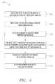
- FIG. 4depicts one embodiment of an example penetration process 400 performed within a living body.
- distal end 105 of elongated member 104is advanced into proximity with body tissue 300 .
- inner core 106is rotated radially around longitudinal axis 208 and at 406 , tissue 300 is imaged to locate optimum penetration region 302 .
- tissue 300is imaged to locate optimum penetration region 302 .
- the distal end of inner core 106is advanced past distal end 105 of member 104 such that imager 108 is placed into contact with tissue 300 at optimum region 302 . It should be noted that the rotation of inner core 106 can be initiated after it has already been advanced from within member 104 , however, this sacrifices any imaging capability until inner core 106 begins rotating.
- tissue 300is penetrated with imager 108 to create opening 306 .
- imager 108is preferably imaging to provide a more accurate penetration of tissue 300 and to ensure that inner core 106 remains placed over region 302 .
- elongated memberis advanced through opening 306 .
- the rate of penetration of tissue 300is dependent on the type of body tissue 300 as well as the rate of rotation of inner core 106 , the shape and configuration of transducer 108 and the axial force applied to advance inner core 106 .
- a low rate of penetrationis desired in order to increase the accuracy and precision in penetration as well as to reduce the risk of overshoot.
- a low rate of penetrationcan still require a high amount of axial force or an abrasive configuration if the body tissue 300 is very hard or resilient to penetration.
- System 100can be configured to penetrate all types of body tissue 300 and transducer 108 can be independently configured to facilitate penetration of each type of body tissue 300 .
- softer tissuesgenerally require less abrasive configurations than harder tissues.
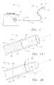
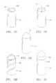
- transducer 108can assume a typical transducer shape where distal end 500 is rounded, such as in the embodiment depicted in FIG. 5A .
- distal end 500 of transducer 108can be substantially flat. Both of these embodiments reduce the risk that transducer 108 will inadvertently penetrate the interior of elongated member 104 .
- Penetration of elongated member 104is not desirable because it can damage surrounding tissue, result in loss of catheter fluid 109 and even separation of elongated member 104 , in which case surgery may be required to remove the severed portion.
- FIGS. 5C-Ddepict other embodiments of transducer 108 . These embodiments depict transducer 108 in a related structural configuration, including electrical connection 501 .
- distal end 500 of transducer 108is rounded with a substantially flat surface, while in the embodiment depicted in FIG. 5D , the flat surface located at distal end 500 is offset at an angle to facilitate penetration of body tissue 300 .
- FIGS. 5E-Idepict various embodiments of transducer 108 configured to penetrate a harder tissue 300 or to penetrate tissue at a faster rate.
- FIG. 5Edepicts an embodiment where distal end 500 includes an abrasive surface 502 and a pointed tip. Abrasive surface 502 can be attached in any manner or it can be formed on distal end 500 directly.
- FIG. 5Fdepicts a similar embodiment where distal end 500 includes protrusions 504 . Again, protrusions 504 can be formed directly on transducer 108 or can be separately attached. The shape and configuration of protrusions 504 is dependent on and may vary with the individual application.
- FIGS. 5G-Idepict embodiments of transducer 108 where distal end 500 is pointed to facilitate penetration.
- distal end 500is pointed but the surface of transducer 108 is relatively smooth.
- distal end 500is also pointed but the surface of transducer 108 includes flute 506 , which is configured to cut tissue 300 .
- This and similar embodimentscan be used in procedures where a very hard tissue 300 , such as bone or plaque, is penetrated.
- FIG. 5Idepicts an embodiment where distal end 500 is coupled with a drill member 508 .
- transducer 108is configured to both facilitate penetration and at the same time allow imaging to take place without significant obstruction.
- imager 108utilizes an alternative type of imaging
- a similar allowance between penetration and imaging capabilityis also envisioned.
- end 500will affect the risk of snagging or catching tissue 300 during penetration, which could result in inadvertent severance of inner core 106 .
- One of skill in the artwill balance the nature and type of tissue 300 with the risks of inadvertent penetration of member 104 and inadvertent damage to inner core 106 and the surrounding tissue when determining the embodiment of transducer 108 that is most suitable for the application.
- the rate of penetrationis dependent on the rate of rotation of inner core 106 as well as the axial force applied to inner core 106 .
- a high rate of rotation of inner corewill result in a higher rate of penetration.
- System 100can operate with any rate of rotation. However, because the rotation rate can directly effect the imaging capability, system 100 is preferably designed to achieve the desired rate of penetration while remaining within a rotation rate suitable for imaging. For instance, in one embodiment, inner core 106 rotates at a rate at approximately 840-1800 revolutions per minute and there are approximately 256 transducing cycles per rotation. In this embodiment, the rate of rotation is independent of the number of transducing cycles in each rotation.
- the rate of penetrationis also dependent on the axial force applied to inner core 106 , where a higher axial force pushing inner core 106 distally towards tissue 300 results in a higher rate of penetration.
- a higher axial forceplaces stress on catheter 102 and could force catheter to bend and rupture surrounding body tissues.
- a higher axial forcecould result cause inner core 106 to overshoot and damage surrounding tissue.
- an appropriate amount of axial forceshould be used for each particular application.
- control system 114may be configured to measure the level of torque applied to inner core 106 .
- Control system 114can then reduce the rate of rotation of inner core 106 or stop the rotation altogether if the maximum torque threshold is reached in order to prevent buckling, breakage, severance or any other undesirable torque-induced effects. Furthermore, control system 114 can output the torque measurement to imaging system 112 where it can be displayed and monitored by a user.
- the level of torquecan be correlated to the point where inner core 106 comes into contact with body tissue 300 and penetrates tissue 300 .
- the added friction caused by the penetration processincreases the level of torque applied to inner core 106 .
- system 100can indicate when penetration of tissue 300 has begun and when inner core 106 has penetrated tissue 300 entirely.
- a pre-determined level of torqueindicates when core 106 has penetrated all of tissue 300 and control system 114 is configured to stop rotation once this pre-determined level is reached. This reduces the risk of overshoot.
- the pre-determined levelwill vary dependent upon the application and the nature of tissue 300 .
- a baseline torque levelis determined when system 100 is rotating but not penetrating tissue and the predetermined level is set to this baseline value.
- Control system 114configured to measure the torque level, recognizes this decrease and terminates the rotation to prevent damage to any surrounding tissues.
- the pre-determined levelcan be set at or just below the torque threshold to prevent damage to core 106 .
- FIG. 6depicts one embodiment of system 100 , including inner core 106 in an extended state.
- Direction 202is measured by offset angle 600 , which is the angular offset of direction 202 from longitudinal center axis 208 .
- direction 202is the direction in which transducer 108 sends and receives acoustic or other imaging signals. Accordingly, direction 202 determines where transducer 108 can image.
- offset angle 600is 90 degrees
- direction 202is perpendicular with axis 208 and transducer 108 is in a side facing configuration and can image body tissue located along the sides of transducer 108 .
- transducer 108When offset angle 600 is, decreased, transducer 108 is capable of imaging body tissue located distally to transducer 108 and is in a forward-facing configuration. As offset angle 600 decreases, transducer 108 is capable of imaging body tissue located further distally to transducer 108 . This may be desirable when the user wants system 100 to image body tissue 300 located distal to transducer 108 in order to locate optimum penetration region 302 .
- offset angle 600is too low, for instance if offset angle 600 were 0 degrees, system 100 may not create a desired body tissue image. This is because imaging system 112 requires transducer 108 to image multiple different locations in every rotation and an offset angle of 0 degrees would allow transducer 108 to image only one location directly distal to transducer 108 along axis 208 .
- the minimum offset angle 600varies accordingly with the imaging capabilities of system 100 . Generally, a lower offset angle will allow tissue located more distally to transducer 108 to be imaged, however the image is typically reduced in quality because image interpretation becomes more difficult. Therefore, the offset angle 600 used may be varied based on the needs of each individual application.
- direction 202can be perpendicular to axis 208 . For instance, this might be the case if system 100 were implemented in an angioplasty procedure and catheter 102 was inserted into a body lumen requiring imaging capability of tissue directly surrounding transducer 108 . Conversely, if forward imaging capabilities are needed, then direction 202 can be any angle less than 90 degrees and preferably greater than the minimum offset angle. In one embodiment, angle 600 is approximately 0-45 degrees, and in a preferred forward-looking embodiment, angle 600 is 45 degrees. However, one of skill in the art will readily recognize any offset angle can be used depending on the needs of the application.
- the systemmay include a suction system configured to suction, or apply negative pressure, within the body.
- the suction systemallows the removal of excess fluid and debris from within the body.
- the suction systemcan remove debris resulting from tissue penetration or blood or other excess bodily fluids.
- the suction systemcan be a vacuum or pump system coupled with proximal end 107 of catheter 102 .
- FIG. 7Adepicts another embodiment of medical system 100 where the suction system (not shown) is coupled with elongated tubular suction member 704 . Both elongated member 104 and elongated suction member 704 are slideably received by elongated tubular guide member 702 .
- the suction systemcan also be configured to apply negative pressure to body tissue 300 and fixate the tissue with respect to inner core 106 .
- Thiscan facilitate penetration process 400 by decreasing the likelihood that inner core 106 will penetrate a region other than optimum penetration region 302 .
- the distal end of suction member 704is placed into proximity with tissue 300 and negative pressure is applied such that the suction system fixates tissue 300 .
- Inner core 106is held in place with respect to suction member 704 by guide member 702 so that no inadvertent movement out of region 302 can occur.
- Tissue 300can also be fixated to stabilize inner core 106 and facilitate imaging of body tissue 300 .
- fixationcan be achieved by the use of other grasping devices such as hooks or very small scale forceps.
- FIG. 7Bdepicts another embodiment of system 100 where guide member 702 includes lumens 708 and 710 , each configured to slideably receive suction member 704 and elongated member 104 , respectively.
- Guide member 702can be configured with additional lumens to accommodate other devices insertable within the body.
- members 104 or 704can be withdrawn to allow insertion of an additional device into lumen 708 or 710 .
- the circumference of guide member 702as depicted in FIG. 7A , can be increased or decreased to accommodate other devices as needed by the individual application.
- space within the bodyis limited and may prevent the use of guide member 702 . If suction is required in these embodiments, in can be applied directly through member 104 .
- the device within each lumencan be withdrawn and replaced by another device in order to allow the use of additional devices without adding additional circumference or lumens to guide member 702 .
- a coagulation deviceconfigured to suppress bleeding.
- coagulation devicesinclude cryo-elements, radio frequency (RF) energy sources, diathermy devices and lasers.
- Coagulation devicesapply energy to body tissue to suppress bleeding by that tissue, i.e., to coagulate blood in the tissue.
- the type of energy applieddepends on the application or the type of coagulation device used, however several examples include thermal, such as with cautery or cryotherapy, RF, mechanical, electrical, acoustical or optical energy.
- a coagulation devicecan be coupled with and applied by elongated member 104 , suction member 704 or an additional elongated member.
- imager 108is coupled with an RF source and functions as a coagulation device by applying RF energy to the surrounding tissue as it rotates.
- a slip ring or commutatorelectrically connects the RF power supply to the outside of inner core 106 , which is then connected to imager 108 .
- This embodimentprovides allows a user to coagulate and penetrate simultaneously.
- inner core 106can be configured to function as an ablation device.
- wire 706is a coagulation device such as a single harmonic wire.
- Single harmonic wire 706physically oscillates in response to acoustic energy applied by a source typically located at the proximal end of harmonic wire 706 .
- Harmonic wire 706can be used to physically penetrate tissue 300 prior to penetration by inner core 106 . This technique facilitates the alignment of inner core 106 in the proper position in optimum region 302 , both by creating a visible target for penetration by inner core 106 and by creating a path for core 106 to follow in the penetration process.
- harmonic wire 706can be used as a guidewire within the body, in addition to the penetration and coagulation functions.
- FIGS. 8A-Bdepict and embodiment of system 100 where elongated member 104 includes multiple prostheses 802 and 804 .
- prostheses 802 and 804are a narrow dumbbell circumference balloon and an expandable stent, respectively.
- FIG. 8Adepicts balloon 802 in an uninflated state, with stent 804 unexpanded.
- This embodimentis configured for use with an application of system 100 directed towards the creation of an opening in tissue 300 , such as the embodiment depicted in FIGS. 3A-G .
- This embodimentalso provides the capability to enlarge and maintain an opening once created. It should be noted that the additional inflation lumen typically necessary to inflate balloon 802 is not shown to provide ease of discussion.
- the narrow dumbbell circumference configuration of balloon 802allows easier alignment and enlargement within the opening.
- the ends of balloon 802 , proximal end 806 and distal end 808can be configured to inflate in sequence or simultaneously, to ensure proper alignment within the opening. For instance, in a proximal-distal inflation, member 104 is inserted within the opening and proximal end 806 is inflated on the proximal side of tissue 300 . Pressure applied to member 104 in a distal direction keeps proximal end 806 in contact with tissue 300 . Distal end 808 is then inflated on the distal side of tissue 300 and balloon 802 is aligned and maintained within the opening.
- FIG. 8Bdepicts balloon 802 in a fully inflated state.
- balloon 802can be inflated in a distal-proximal manner where distal end 808 is inflated prior to proximal end 806 .
- Stent 804expands as balloon 802 inflates and locks into an expanded position aligned directly with the opening. Balloon 802 is then deflated and member 104 is removed leaving stent 804 expanded within the opening and in position to maintain the opening.
- balloon 802 and stent 804can be used separately.
- One example of thisis a self-expanding stent, the use of which is readily recognized by one of skill in the art.
- One of skill in the artwill also recognize the numerous varieties of prostheses 802 and 804 , and also the existence of additional types of prostheses, all of which can be included on member 104 or an addition elongated member and used in conjunction with system 100 .
- Hydrocephalusis a swelling of the interior cerebral ventricles caused by excess cerebro-spinal fluid (CSF).
- CSFcerebro-spinal fluid
- One type of hydrocephalusis non-communicating, or obstructive hydrocephalus, where the flow of CSF is blocked along one or more of the narrow pathways connecting the ventricles.
- a communicating passagewayis created to allow the excess CSF to drain from the swollen ventricles.
- the example procedure described hereinincludes utilizing a percutaneous intraspinal navigation (PIN) technique to place catheter 102 into proximity with a swollen third cerebral ventricle. Catheter 102 is then used to penetrate the tissue of the third ventricle and create an opening or communicating passageway through which the excess CSF can drain.
- PINpercutaneous intraspinal navigation
- FIG. 9depicts various portions of central nervous system 920 of living body 900 in which one embodiment of system 100 can be utilized. More specifically, FIG. 9 depicts lumbar region 902 , dural membrane 904 , brain 906 , spinal canal 908 , spinal cord 910 , cranium 912 , third ventricle 914 , third ventricle membrane 916 , CSF 918 and cistern 919 . Shown within lumbar region 902 are lumbar vertebrae L1, L2, L3, L4 and L5. In this embodiment, system 100 is configured to enable the percutaneous intraspinal navigation of catheter 102 from lumbar region 902 through spinal canal 908 and into proximity with third ventricle 914 .
- Catheter 102preferably includes imager 108 and imaging system 112 , which enables system 100 to image the interior regions of body 900 , which facilitates the navigation of those regions.
- imager 108can use any imaging technique such as acoustic or optical imaging.
- imager 108will be described as an acoustic transducer in this example environment.
- distal end 103 of catheter 102is inserted into spinal canal 708 , also referred to as the spinal subarachnoid space, through lumbar region 902 and dural membrane 904 .
- spinal canal 708also referred to as the spinal subarachnoid space
- the insertion through region 902is preferably in the L3-L4 or L4-L5 spaces, although any insertion location can be used.
- catheter 102is navigated anteriorly through spinal canal 908 with care to avoid damage to spinal cord 910 , as well as other spinal and cranial nerves. Navigation through spinal canal 908 is preferably done with the aid of acoustic imaging, however, other imaging techniques can be substituted. Catheter 102 is then navigated into cranium 912 and into proximity with third ventricle 914 . Due to the narrow regions encountered in navigating through spinal canal 908 , the width of elongated member 104 is kept small, preferably less than 2 mm (millimeter) or 6F (french). In one experimental embodiment, catheter 102 was a 3F catheter and incurred no noticeable damage to spinal cord 910 when navigating spinal canal 908 .
- FIG. 10depicts a closer view of an embodiment of catheter 102 in proximity with third ventricle 914 .
- catheter 102can image third ventricle membrane 916 in order to locate an optimum penetration region in membrane 916 , such as region 302 in FIGS. 3B-3G .
- the optimum penetration region 302is preferably an area of membrane 916 that does not contain blood vessels or arteries that could pose a significant risk of bleeding.
- the presence of achrinoid membranescan obstruct the penetration of membrane 916 by inner core 106 and the optimum penetration region 302 is preferably chosen to avoid achrinoid membranes.
- catheter 102can then be used to penetrate third ventricle membrane 916 to allow excess CSF 918 to drain into cistern 919 and spinal canal 908 . Excess CSF 918 is then absorbed and processed by body 900 and the swollen ventricles return to normal size.
- transducer 108does not require extensive abrasive configurations to penetrate membrane 916 . Furthermore, penetration is facilitated because membrane 916 is under pressure and stretched due to the excess CSF 918 . Therefore, in a preferred embodiment, transducer 108 is configured similar to the embodiment depicted in FIG. 5B , where distal end 500 is substantially flat. This configuration can reduce the risk of damage to any tissue surrounding the penetration region. However, any configuration depicted in FIGS. 5A-G can be used to penetrate membrane 916 .
- elongated member 104is advanced into contact with the optimum penetration region 302 and once in place, rotating inner core 106 is also advanced into contact with the region 302 and penetrates membrane 916 . Again, care is taken to avoid extending inner core 106 further than is needed to create opening 306 .
- stop device 212prevents advancement of inner core 106 once pre-determined length 214 is reached. Opening 306 should be sufficiently large to allow drainage of CSF 918 without closing prematurely. The size of opening 306 is dictated initially by the diameter of transducer 108 . If this size is sufficient for the needs of the procedure, then inner core 106 can be retracted within elongated member 104 and catheter 102 can be withdrawn altogether. If opening 306 needs to be enlarged, elongated member 104 can be advanced through opening 306 .
- a prosthesissuch as balloon 802 depicted in FIGS. 8A-B
- a shuntcan be placed in opening 306 to allow excess CSF 918 to drain continually.
- system 100is configured to suction excess CSF 918 from third ventricle 914 . The use of suction to remove excess CSF 918 can be used when body 900 is not uptaking or processing CSF 918 normally, for instance in the case of communicating hydrocephalus.
- system 100preferably includes a coagulation device as discussed above.
- the coagulation deviceis preferably located on elongated member 104 because of the narrow confines of spinal canal 908 .
- any coagulation devicecan be used provided there is enough space to accommodate the device within spinal canal 908 and the remainder of the navigated path through body 900 .
- Medical system 100can also be implemented in numerous other medical procedures with or without the PIN technique.
- system 100can be configured to actively circulate fluid within body 900 .
- saline or isotonic CSFcan be introduced through member 104 into third ventricle 914 or an area adjacent to the penetration region.
- the excess fluidcan be removed through suction member 904 and this process can be continued to provide active fluid circulation to lavage, or rinse, the cerebral ventricles or other internal portions of the body.
- System 100can be configured to perform tumor biopsies or to implant radioactive material within a tumor.
- System 100can also be configured to implant electrodes within the brain or other parts of the body or can perform electrocorticography or brain stem signal recording.
- system 100can be configured to induce localized hypothermia to areas of the body, in which case system 100 is configured to pump low temperature fluids through elongated member 104 to the localized region.
- imaging system 112includes a magnetic resonance (MR) imaging system that allows the use of catheter 102 with external imaging in real-time.
- MRmagnetic resonance
- catheter 102preferably uses optical imaging and is substantially composed of non-magnetic or non-metallic materials that will not interfere with the MR image.
- metallic materialsif metallic materials are used then they can be withdrawn during the MR imaging.
- a metallic imager 108can be used to navigate catheter 102 into proximity with tissue 300 and, once in place, the metallic imager 108 can be withdrawn and replaced with a non-metallic inner core 106 .
- the penetration processcan then take place using the non-metallic inner core and external MR imaging, which detects the pressure and tissue shifts within body 700 as the penetration process is performed.
- Other techniquessuch as computed tomography (CT), computerized axial tomography (CAT) or fluoroscopy, or any combination of imaging techniques can also be used.
- CTcomputed tomography
- CATcomputerized axial tomography
- fluoroscopyor any combination of imaging techniques can also be used.
- FIG. 11depicts one embodiment of example penetration process 1100 performed within central nervous system 900 .
- distal end 105 of elongated member 104is percutaneously inserted into spinal canal 908 of living body 900 through lumbar region 902 and dural membrane 904 .
- elongated member 104is advanced through spinal canal 908 into proximity with third ventricle 914 .
- inner core 106is rotated radially around longitudinal axis 208 and at 1108 , third ventricle membrane 916 is imaged to locate optimum penetration region 302 .
- the distal end of inner core 106is advanced past distal end 105 of member 104 such that transducer 108 is placed into contact with third ventricle membrane 916 at optimum region 302 . It should be noted that the rotation of inner core 106 can be initiated after it has already been advanced from within member 104 , however, no imaging capability is usually available until inner core 106 begins rotating. Then, at 1112 , membrane 916 is penetrated with distal end 500 of transducer 108 . Finally, at 1114 , inner core 106 is retracted and excess CSF 918 is allowed to drain into spinal canal 908 .
Landscapes
- Health & Medical Sciences (AREA)
- Life Sciences & Earth Sciences (AREA)
- Surgery (AREA)
- Engineering & Computer Science (AREA)
- General Health & Medical Sciences (AREA)
- Veterinary Medicine (AREA)
- Biomedical Technology (AREA)
- Heart & Thoracic Surgery (AREA)
- Medical Informatics (AREA)
- Molecular Biology (AREA)
- Public Health (AREA)
- Animal Behavior & Ethology (AREA)
- Pathology (AREA)
- Biophysics (AREA)
- Physics & Mathematics (AREA)
- Nuclear Medicine, Radiotherapy & Molecular Imaging (AREA)
- Optics & Photonics (AREA)
- Radiology & Medical Imaging (AREA)
- Orthopedic Medicine & Surgery (AREA)
- Ultra Sonic Daignosis Equipment (AREA)
- Media Introduction/Drainage Providing Device (AREA)
- Surgical Instruments (AREA)
Abstract
Description
Claims (16)
Priority Applications (1)
| Application Number | Priority Date | Filing Date | Title |
|---|---|---|---|
| US12/749,234US8005529B2 (en) | 2003-03-21 | 2010-03-29 | Systems and methods for internal tissue penetration |
Applications Claiming Priority (2)
| Application Number | Priority Date | Filing Date | Title |
|---|---|---|---|
| US10/394,079US7715896B2 (en) | 2003-03-21 | 2003-03-21 | Systems and methods for internal tissue penetration |
| US12/749,234US8005529B2 (en) | 2003-03-21 | 2010-03-29 | Systems and methods for internal tissue penetration |
Related Parent Applications (1)
| Application Number | Title | Priority Date | Filing Date |
|---|---|---|---|
| US10/394,079ContinuationUS7715896B2 (en) | 2003-03-21 | 2003-03-21 | Systems and methods for internal tissue penetration |
Publications (2)
| Publication Number | Publication Date |
|---|---|
| US20100185054A1 US20100185054A1 (en) | 2010-07-22 |
| US8005529B2true US8005529B2 (en) | 2011-08-23 |
Family
ID=32988288
Family Applications (2)
| Application Number | Title | Priority Date | Filing Date |
|---|---|---|---|
| US10/394,079Active2026-09-11US7715896B2 (en) | 2003-03-21 | 2003-03-21 | Systems and methods for internal tissue penetration |
| US12/749,234Expired - LifetimeUS8005529B2 (en) | 2003-03-21 | 2010-03-29 | Systems and methods for internal tissue penetration |
Family Applications Before (1)
| Application Number | Title | Priority Date | Filing Date |
|---|---|---|---|
| US10/394,079Active2026-09-11US7715896B2 (en) | 2003-03-21 | 2003-03-21 | Systems and methods for internal tissue penetration |
Country Status (3)
| Country | Link |
|---|---|
| US (2) | US7715896B2 (en) |
| AU (1) | AU2003300095A1 (en) |
| WO (1) | WO2004093666A1 (en) |
Cited By (2)
| Publication number | Priority date | Publication date | Assignee | Title |
|---|---|---|---|---|
| US20060149162A1 (en)* | 2004-11-29 | 2006-07-06 | Derek Daw | Graphical user interface for tissue biopsy system |
| US10314563B2 (en) | 2014-11-26 | 2019-06-11 | Devicor Medical Products, Inc. | Graphical user interface for biopsy device |
Families Citing this family (88)
| Publication number | Priority date | Publication date | Assignee | Title |
|---|---|---|---|---|
| DE102004008373B3 (en)* | 2004-02-20 | 2005-09-29 | Siemens Ag | Apparatus for performing and monitoring endovascular brachytherapy |
| DE102004008371B4 (en)* | 2004-02-20 | 2006-05-24 | Siemens Ag | atherectomy |
| CA2565106C (en) | 2004-05-25 | 2013-11-05 | Chestnut Medical Technologies, Inc. | Flexible vascular occluding device |
| US8267985B2 (en) | 2005-05-25 | 2012-09-18 | Tyco Healthcare Group Lp | System and method for delivering and deploying an occluding device within a vessel |
| US8617234B2 (en) | 2004-05-25 | 2013-12-31 | Covidien Lp | Flexible vascular occluding device |
| US20060206200A1 (en) | 2004-05-25 | 2006-09-14 | Chestnut Medical Technologies, Inc. | Flexible vascular occluding device |
| US9675476B2 (en) | 2004-05-25 | 2017-06-13 | Covidien Lp | Vascular stenting for aneurysms |
| CA2758946C (en) | 2004-05-25 | 2014-10-21 | Tyco Healthcare Group Lp | Vascular stenting for aneurysms |
| US8623067B2 (en) | 2004-05-25 | 2014-01-07 | Covidien Lp | Methods and apparatus for luminal stenting |
| CN100421613C (en)* | 2004-11-16 | 2008-10-01 | 医电科技股份有限公司 | Video Intubation Assist Device |
| WO2006061829A1 (en)* | 2004-12-06 | 2006-06-15 | Glucon Inc. | Photoacoustic intravascular probe |
| JP4668643B2 (en)* | 2005-02-23 | 2011-04-13 | オリンパスメディカルシステムズ株式会社 | Endoscope device |
| US8568317B1 (en)* | 2005-09-27 | 2013-10-29 | Nuvasive, Inc. | System and methods for nerve monitoring |
| US20070092591A1 (en)* | 2005-10-24 | 2007-04-26 | Cyberonics, Inc. | Vacuum mandrel for use in fabricating an implantable electrode |
| US8152833B2 (en) | 2006-02-22 | 2012-04-10 | Tyco Healthcare Group Lp | Embolic protection systems having radiopaque filter mesh |
| JP4868970B2 (en)* | 2006-08-03 | 2012-02-01 | オリンパスメディカルシステムズ株式会社 | Rotating self-propelled endoscope system |
| JP4994771B2 (en)* | 2006-10-06 | 2012-08-08 | オリンパスメディカルシステムズ株式会社 | Rotating self-propelled endoscope system |
| US8582934B2 (en)* | 2007-11-12 | 2013-11-12 | Lightlab Imaging, Inc. | Miniature optical elements for fiber-optic beam shaping |
| US8696695B2 (en) | 2009-04-28 | 2014-04-15 | Avinger, Inc. | Guidewire positioning catheter |
| US8062316B2 (en) | 2008-04-23 | 2011-11-22 | Avinger, Inc. | Catheter system and method for boring through blocked vascular passages |
| US9125562B2 (en) | 2009-07-01 | 2015-09-08 | Avinger, Inc. | Catheter-based off-axis optical coherence tomography imaging system |
| US9788790B2 (en) | 2009-05-28 | 2017-10-17 | Avinger, Inc. | Optical coherence tomography for biological imaging |
| US20100191168A1 (en)* | 2009-01-29 | 2010-07-29 | Trustees Of Tufts College | Endovascular cerebrospinal fluid shunt |
| WO2011003006A2 (en) | 2009-07-01 | 2011-01-06 | Avinger, Inc. | Atherectomy catheter with laterally-displaceable tip |
| US8926590B2 (en) | 2009-12-22 | 2015-01-06 | Lightlab Imaging, Inc. | Torque limiter for an OCT catheter |
| US8206377B2 (en)* | 2009-12-22 | 2012-06-26 | Lightlab Imaging, Inc. | Torque limiter for an OCT catheter |
| US20130041285A1 (en)* | 2010-04-27 | 2013-02-14 | Apriomed Ab | Biopsy extraction unit |
| US10548478B2 (en) | 2010-07-01 | 2020-02-04 | Avinger, Inc. | Balloon atherectomy catheters with imaging |
| US9345510B2 (en) | 2010-07-01 | 2016-05-24 | Avinger, Inc. | Atherectomy catheters with longitudinally displaceable drive shafts |
| US11382653B2 (en) | 2010-07-01 | 2022-07-12 | Avinger, Inc. | Atherectomy catheter |
| WO2014039096A1 (en) | 2012-09-06 | 2014-03-13 | Avinger, Inc. | Re-entry stylet for catheter |
| US20130310645A1 (en)* | 2011-01-28 | 2013-11-21 | Koninklijke Philips N.V. | Optical sensing for relative tracking of endoscopes |
| EP2691038B1 (en) | 2011-03-28 | 2016-07-20 | Avinger, Inc. | Occlusion-crossing devices, imaging, and atherectomy devices |
| US9949754B2 (en) | 2011-03-28 | 2018-04-24 | Avinger, Inc. | Occlusion-crossing devices |
| US20140094697A1 (en) | 2011-05-27 | 2014-04-03 | Lightlab Imaging, Inc. | Optical coherence tomography and pressure based systems and methods |
| JP5939746B2 (en)* | 2011-06-09 | 2016-06-22 | 株式会社トプコン | Optical tomography probe |
| EP3653151A1 (en) | 2011-10-17 | 2020-05-20 | Avinger, Inc. | Atherectomy catheters and non-contact actuation mechanism for catheters |
| JP6170931B2 (en) | 2011-10-31 | 2017-07-26 | ボストン サイエンティフィック サイムド,インコーポレイテッドBoston Scientific Scimed,Inc. | Endoscopic instrument with a deflectable distal tool |
| US9345406B2 (en) | 2011-11-11 | 2016-05-24 | Avinger, Inc. | Occlusion-crossing devices, atherectomy devices, and imaging |
| JP6320936B2 (en) | 2012-01-25 | 2018-05-09 | ボストン サイエンティフィック サイムド,インコーポレイテッドBoston Scientific Scimed,Inc. | Medical device with movable distal tool |
| EP2849660B1 (en) | 2012-05-14 | 2021-08-25 | Avinger, Inc. | Atherectomy catheter drive assemblies |
| US9557156B2 (en) | 2012-05-14 | 2017-01-31 | Avinger, Inc. | Optical coherence tomography with graded index fiber for biological imaging |
| WO2013172970A1 (en) | 2012-05-14 | 2013-11-21 | Avinger, Inc. | Atherectomy catheters with imaging |
| US9498247B2 (en) | 2014-02-06 | 2016-11-22 | Avinger, Inc. | Atherectomy catheters and occlusion crossing devices |
| US11284916B2 (en) | 2012-09-06 | 2022-03-29 | Avinger, Inc. | Atherectomy catheters and occlusion crossing devices |
| US9301831B2 (en) | 2012-10-30 | 2016-04-05 | Covidien Lp | Methods for attaining a predetermined porosity of a vascular device |
| US9452070B2 (en) | 2012-10-31 | 2016-09-27 | Covidien Lp | Methods and systems for increasing a density of a region of a vascular device |
| US9943427B2 (en) | 2012-11-06 | 2018-04-17 | Covidien Lp | Shaped occluding devices and methods of using the same |
| US9157174B2 (en) | 2013-02-05 | 2015-10-13 | Covidien Lp | Vascular device for aneurysm treatment and providing blood flow into a perforator vessel |
| WO2014163601A1 (en) | 2013-03-11 | 2014-10-09 | Lightlab Imaging, Inc. | Friction torque limiter for an imaging catheter |
| WO2014143064A1 (en)* | 2013-03-15 | 2014-09-18 | Avinger, Inc. | Chronic total occlusion crossing devices with imaging |
| US11096717B2 (en) | 2013-03-15 | 2021-08-24 | Avinger, Inc. | Tissue collection device for catheter |
| CN105228514B (en) | 2013-03-15 | 2019-01-22 | 阿维格公司 | Optical Pressure Sensor Assembly |
| WO2014145858A2 (en) | 2013-03-15 | 2014-09-18 | Bitol Designs, Llc | Occlusion resistant catheter and method of use |
| EP3019096B1 (en) | 2013-07-08 | 2023-07-05 | Avinger, Inc. | System for identification of elastic lamina to guide interventional therapy |
| JP6637430B2 (en) | 2014-01-15 | 2020-01-29 | タフツ メディカル センター, インク.Tufts Medical Center, Inc. | Intravascular cerebrospinal fluid shunt |
| US9737696B2 (en) | 2014-01-15 | 2017-08-22 | Tufts Medical Center, Inc. | Endovascular cerebrospinal fluid shunt |
| MX2016010141A (en) | 2014-02-06 | 2017-04-06 | Avinger Inc | Atherectomy catheters and occlusion crossing devices. |
| US9788856B2 (en) | 2014-03-11 | 2017-10-17 | Stryker European Holdings I, Llc | Endoscopic surgical systems and methods |
| US10357277B2 (en) | 2014-07-08 | 2019-07-23 | Avinger, Inc. | High speed chronic total occlusion crossing devices |
| CN107148293B (en) | 2014-10-31 | 2020-08-11 | 西瑞维斯克有限责任公司 | Method and system for treating hydrocephalus |
| US10568520B2 (en) | 2015-07-13 | 2020-02-25 | Avinger, Inc. | Micro-molded anamorphic reflector lens for image guided therapeutic/diagnostic catheters |
| US10314593B2 (en) | 2015-09-23 | 2019-06-11 | Covidien Lp | Occlusive devices |
| CN105105832B (en)* | 2015-10-14 | 2017-06-23 | 中国人民解放军第二军医大学 | Wear the protractor of gastroscopic biopsy pipeline |
| JP6138405B1 (en)* | 2015-10-27 | 2017-05-31 | オリンパス株式会社 | Insertion device |
| US10272230B2 (en) | 2015-10-30 | 2019-04-30 | Cerevasc, Llc | Systems and methods for treating hydrocephalus |
| JP6927986B2 (en) | 2016-01-25 | 2021-09-01 | アビンガー・インコーポレイテッドAvinger, Inc. | OCT imaging catheter with delay compensation |
| EP3435892B1 (en) | 2016-04-01 | 2024-04-03 | Avinger, Inc. | Atherectomy catheter with serrated cutter |
| US11344327B2 (en) | 2016-06-03 | 2022-05-31 | Avinger, Inc. | Catheter device with detachable distal end |
| WO2018006041A1 (en) | 2016-06-30 | 2018-01-04 | Avinger, Inc. | Atherectomy catheter with shapeable distal tip |
| WO2018071600A1 (en) | 2016-10-11 | 2018-04-19 | Cerevasc, Llc | Methods and systems for treating hydrocephalus |
| EP4018946A1 (en) | 2017-05-03 | 2022-06-29 | Medtronic Vascular, Inc. | Tissue-removing catheter |
| US11690645B2 (en) | 2017-05-03 | 2023-07-04 | Medtronic Vascular, Inc. | Tissue-removing catheter |
| US12193866B1 (en)* | 2017-05-26 | 2025-01-14 | Abid Qureshi | Intraosseous and intramedullary visualization |
| EP3716854B1 (en)* | 2017-11-29 | 2025-05-28 | Avent, Inc. | System and method for mounting an ultrasound transducer on a needle |
| EP3762083B1 (en) | 2018-03-08 | 2025-02-12 | CereVasc, Inc. | Systems for minimally invasive drug delivery to a subarachnoid space |
| WO2019191538A1 (en) | 2018-03-29 | 2019-10-03 | Asahi Intecc Co., Ltd. | Catheter and recanalization catheter system |
| US12167867B2 (en) | 2018-04-19 | 2024-12-17 | Avinger, Inc. | Occlusion-crossing devices |
| CN118697424A (en) | 2018-11-16 | 2024-09-27 | 美敦力瓦斯科尔勒公司 | Tissue Removal Catheter |
| US12420069B2 (en) | 2018-12-19 | 2025-09-23 | Covidien Lp | Internal carotid artery thrombectomy devices and methods |
| US11819236B2 (en) | 2019-05-17 | 2023-11-21 | Medtronic Vascular, Inc. | Tissue-removing catheter |
| CN114746033B (en) | 2019-10-18 | 2025-01-10 | 阿维格公司 | Blocking crossing device |
| US20210113073A1 (en)* | 2019-10-22 | 2021-04-22 | Sharon A. Hibbs | Large mass removal endoscope apparatus |
| JP2023524042A (en)* | 2020-04-28 | 2023-06-08 | マヨ ファウンデーション フォー メディカル エデュケーション アンド リサーチ | Devices and methods for accessing the intradural compartment and treating intracranial hematomas |
| EP4149582A1 (en) | 2020-05-11 | 2023-03-22 | Minnetronix Neuro, Inc. | Filtering cassettes and filtering systems |
| WO2022094228A1 (en) | 2020-10-30 | 2022-05-05 | Boston Scientific Scimed, Inc. | Atherectomy burrs with blood flow enhancements |
| US20220192743A1 (en)* | 2020-12-18 | 2022-06-23 | Case Western Reserve University | Integrated imaging ablation catheter |
| US12151058B2 (en) | 2022-11-04 | 2024-11-26 | Mayo Foundation For Medical Education And Research | Systems, devices, and methods for accessing a subdural space |
Citations (62)
| Publication number | Priority date | Publication date | Assignee | Title |
|---|---|---|---|---|
| US4474179A (en) | 1981-05-20 | 1984-10-02 | F. L. Fischer Gmbh & Co. | Method and apparatus for the high frequency coagulation of protein for surgical purposes |
| US4898575A (en) | 1987-08-31 | 1990-02-06 | Medinnovations, Inc. | Guide wire following tunneling catheter system and method for transluminal arterial atherectomy |
| US4917097A (en) | 1987-10-27 | 1990-04-17 | Endosonics Corporation | Apparatus and method for imaging small cavities |
| US4935025A (en) | 1989-01-30 | 1990-06-19 | Bundy Mark A | Transluminal lysing device |
| US4998933A (en) | 1988-06-10 | 1991-03-12 | Advanced Angioplasty Products, Inc. | Thermal angioplasty catheter and method |
| US5054492A (en) | 1990-12-17 | 1991-10-08 | Cardiovascular Imaging Systems, Inc. | Ultrasonic imaging catheter having rotational image correlation |
| US5078717A (en) | 1989-04-13 | 1992-01-07 | Everest Medical Corporation | Ablation catheter with selectively deployable electrodes |
| US5078723A (en) | 1989-05-08 | 1992-01-07 | Medtronic, Inc. | Atherectomy device |
| US5122137A (en) | 1990-04-27 | 1992-06-16 | Boston Scientific Corporation | Temperature controlled rf coagulation |
| US5125928A (en) | 1989-04-13 | 1992-06-30 | Everest Medical Corporation | Ablation catheter with selectively deployable electrodes |
| US5207681A (en) | 1987-10-26 | 1993-05-04 | Neurodynamics, Inc. | Drill guide apparatus for perpendicular perforation of the cranium |
| US5267960A (en) | 1990-03-19 | 1993-12-07 | Omnitron International Inc. | Tissue engaging catheter for a radioactive source wire |
| US5281218A (en) | 1992-06-05 | 1994-01-25 | Cardiac Pathways Corporation | Catheter having needle electrode for radiofrequency ablation |
| US5306244A (en) | 1984-05-14 | 1994-04-26 | Surgical Systems & Instruments, Inc. | Method of guidewire insertion |
| US5342357A (en) | 1992-11-13 | 1994-08-30 | American Cardiac Ablation Co., Inc. | Fluid cooled electrosurgical cauterization system |
| US5373849A (en) | 1993-01-19 | 1994-12-20 | Cardiovascular Imaging Systems, Inc. | Forward viewing imaging catheter |
| US5403311A (en) | 1993-03-29 | 1995-04-04 | Boston Scientific Corporation | Electro-coagulation and ablation and other electrotherapeutic treatments of body tissue |
| US5429582A (en) | 1991-06-14 | 1995-07-04 | Williams; Jeffery A. | Tumor treatment |
| US5438997A (en) | 1991-03-13 | 1995-08-08 | Sieben; Wayne | Intravascular imaging apparatus and methods for use and manufacture |
| US5596990A (en) | 1995-06-06 | 1997-01-28 | Yock; Paul | Rotational correlation of intravascular ultrasound image with guide catheter position |
| US5599346A (en) | 1993-11-08 | 1997-02-04 | Zomed International, Inc. | RF treatment system |
| US5606974A (en) | 1995-05-02 | 1997-03-04 | Heart Rhythm Technologies, Inc. | Catheter having ultrasonic device |
| US5636644A (en) | 1995-03-17 | 1997-06-10 | Applied Medical Resources Corporation | Method and apparatus for endoconduit targeting |
| US5649941A (en) | 1995-01-10 | 1997-07-22 | Interventional Technologies Inc. | Improved vascular incisor/dilator |
| US5651364A (en) | 1986-02-28 | 1997-07-29 | Cardiovascular Imaging Systems, Inc. | Method and apparatus for intravascular |
| US5665062A (en) | 1995-01-23 | 1997-09-09 | Houser; Russell A. | Atherectomy catheter and RF cutting method |
| US5690117A (en) | 1995-03-20 | 1997-11-25 | Gilbert; John W. | Ultrasonic-fiberoptic imaging ventricular catheter |
| US5699805A (en) | 1996-06-20 | 1997-12-23 | Mayo Foundation For Medical Education And Research | Longitudinal multiplane ultrasound transducer underfluid catheter system |
| US5713363A (en) | 1991-11-08 | 1998-02-03 | Mayo Foundation For Medical Education And Research | Ultrasound catheter and method for imaging and hemodynamic monitoring |
| US5724975A (en) | 1996-12-12 | 1998-03-10 | Plc Medical Systems, Inc. | Ultrasonic detection system for transmyocardial revascularization |
| US5752518A (en) | 1996-10-28 | 1998-05-19 | Ep Technologies, Inc. | Systems and methods for visualizing interior regions of the body |
| US5810764A (en) | 1992-01-07 | 1998-09-22 | Arthrocare Corporation | Resecting loop electrode and method for electrosurgical cutting and ablation |
| US5829439A (en) | 1995-06-28 | 1998-11-03 | Hitachi Medical Corporation | Needle-like ultrasonic probe for ultrasonic diagnosis apparatus, method of producing same, and ultrasonic diagnosis apparatus using same |
| US5830222A (en) | 1995-10-13 | 1998-11-03 | Transvascular, Inc. | Device, system and method for intersititial transvascular intervention |
| US5830224A (en) | 1996-03-15 | 1998-11-03 | Beth Israel Deaconess Medical Center | Catheter apparatus and methodology for generating a fistula on-demand between closely associated blood vessels at a pre-chosen anatomic site in-vivo |
| US5904711A (en) | 1996-02-08 | 1999-05-18 | Heartport, Inc. | Expandable thoracoscopic defibrillation catheter system and method |
| US5921982A (en) | 1993-07-30 | 1999-07-13 | Lesh; Michael D. | Systems and methods for ablating body tissue |
| US5928229A (en) | 1993-11-08 | 1999-07-27 | Rita Medical Systems, Inc. | Tumor ablation apparatus |
| US5980480A (en) | 1996-07-11 | 1999-11-09 | Cs Fluids, Inc. | Method and apparatus for treating adult-onset dementia of the alzheimer's type |
| US6080152A (en) | 1998-06-05 | 2000-06-27 | Medical Scientific, Inc. | Electrosurgical instrument |
| US6086534A (en) | 1997-03-07 | 2000-07-11 | Cardiogenesis Corporation | Apparatus and method of myocardial revascularization using ultrasonic pulse-echo distance ranging |
| US6120516A (en) | 1997-02-28 | 2000-09-19 | Lumend, Inc. | Method for treating vascular occlusion |
| US6152938A (en) | 1997-08-19 | 2000-11-28 | Curry; Paul | Device for opening blocked tubes |
| US6157852A (en) | 1998-01-15 | 2000-12-05 | Lumend, Inc. | Catheter apparatus for treating arterial occlusions |
| US6183442B1 (en)* | 1998-03-02 | 2001-02-06 | Board Of Regents Of The University Of Texas System | Tissue penetrating device and methods for using same |
| US6245026B1 (en) | 1996-07-29 | 2001-06-12 | Farallon Medsystems, Inc. | Thermography catheter |
| US6277064B1 (en) | 1997-12-30 | 2001-08-21 | Inbae Yoon | Surgical instrument with rotatably mounted offset endoscope |
| US6302875B1 (en) | 1996-10-11 | 2001-10-16 | Transvascular, Inc. | Catheters and related devices for forming passageways between blood vessels or other anatomical structures |
| US6319189B1 (en) | 1999-09-13 | 2001-11-20 | Isotron, Inc. | Methods for treating solid tumors using neutron therapy |
| US6371919B1 (en) | 1997-06-30 | 2002-04-16 | Eva Corporation | Method and apparatus for the surgical repair of aneurysms |
| US6375615B1 (en) | 1995-10-13 | 2002-04-23 | Transvascular, Inc. | Tissue penetrating catheters having integral imaging transducers and their methods of use |
| US6387043B1 (en) | 1998-05-13 | 2002-05-14 | Inbae Yoon | Penetrating endoscope and endoscopic surgical instrument with CMOS image sensor and display |
| US6394956B1 (en) | 2000-02-29 | 2002-05-28 | Scimed Life Systems, Inc. | RF ablation and ultrasound catheter for crossing chronic total occlusions |
| US6415823B1 (en) | 1999-04-30 | 2002-07-09 | Medtronic, Inc | Catheter tip insert |
| US6432104B1 (en) | 1998-04-15 | 2002-08-13 | Scimed Life Systems, Inc. | Electro-cautery catherer |
| US6464693B1 (en) | 2000-03-06 | 2002-10-15 | Plc Medical Systems, Inc. | Myocardial revascularization |
| US6485465B2 (en) | 2000-03-29 | 2002-11-26 | Medtronic Minimed, Inc. | Methods, apparatuses, and uses for infusion pump fluid pressure and force detection |
| US20030014016A1 (en)* | 2001-07-13 | 2003-01-16 | Purdy Phillip D. | Methods and apparatuses for navigating the subaracnhnoid space |
| US6514248B1 (en) | 1999-10-15 | 2003-02-04 | Neothermia Corporation | Accurate cutting about and into tissue volumes with electrosurgically deployed electrodes |
| US20030088245A1 (en) | 2001-11-02 | 2003-05-08 | Arthrocare Corporation | Methods and apparatus for electrosurgical ventriculostomy |
| US6575928B2 (en) | 1998-11-10 | 2003-06-10 | Eunoe, Inc. | Devices and methods for removing cerebrospinal fluids from a patient's CSF space |
| US6925323B2 (en) | 1992-07-06 | 2005-08-02 | Phillip Jack Snoke | System for enhancing visibility in the epidural space |
Family Cites Families (1)
| Publication number | Priority date | Publication date | Assignee | Title |
|---|---|---|---|---|
| US6150354A (en)* | 1987-01-15 | 2000-11-21 | Bonnie Davis | Compounds for the treatment of Alzheimer's disease |
- 2003
- 2003-03-21USUS10/394,079patent/US7715896B2/enactiveActive
- 2003-12-19WOPCT/US2003/041617patent/WO2004093666A1/ennot_activeApplication Discontinuation
- 2003-12-19AUAU2003300095Apatent/AU2003300095A1/ennot_activeAbandoned
- 2010
- 2010-03-29USUS12/749,234patent/US8005529B2/ennot_activeExpired - Lifetime
Patent Citations (66)
| Publication number | Priority date | Publication date | Assignee | Title |
|---|---|---|---|---|
| US4474179A (en) | 1981-05-20 | 1984-10-02 | F. L. Fischer Gmbh & Co. | Method and apparatus for the high frequency coagulation of protein for surgical purposes |
| US5306244A (en) | 1984-05-14 | 1994-04-26 | Surgical Systems & Instruments, Inc. | Method of guidewire insertion |
| US5651364A (en) | 1986-02-28 | 1997-07-29 | Cardiovascular Imaging Systems, Inc. | Method and apparatus for intravascular |
| US4898575A (en) | 1987-08-31 | 1990-02-06 | Medinnovations, Inc. | Guide wire following tunneling catheter system and method for transluminal arterial atherectomy |
| US5207681A (en) | 1987-10-26 | 1993-05-04 | Neurodynamics, Inc. | Drill guide apparatus for perpendicular perforation of the cranium |
| US4917097A (en) | 1987-10-27 | 1990-04-17 | Endosonics Corporation | Apparatus and method for imaging small cavities |
| US4998933A (en) | 1988-06-10 | 1991-03-12 | Advanced Angioplasty Products, Inc. | Thermal angioplasty catheter and method |
| US4935025A (en) | 1989-01-30 | 1990-06-19 | Bundy Mark A | Transluminal lysing device |
| US5125928A (en) | 1989-04-13 | 1992-06-30 | Everest Medical Corporation | Ablation catheter with selectively deployable electrodes |
| US5078717A (en) | 1989-04-13 | 1992-01-07 | Everest Medical Corporation | Ablation catheter with selectively deployable electrodes |
| US5078723A (en) | 1989-05-08 | 1992-01-07 | Medtronic, Inc. | Atherectomy device |
| US5267960A (en) | 1990-03-19 | 1993-12-07 | Omnitron International Inc. | Tissue engaging catheter for a radioactive source wire |
| US5122137A (en) | 1990-04-27 | 1992-06-16 | Boston Scientific Corporation | Temperature controlled rf coagulation |
| US5054492A (en) | 1990-12-17 | 1991-10-08 | Cardiovascular Imaging Systems, Inc. | Ultrasonic imaging catheter having rotational image correlation |
| US5438997A (en) | 1991-03-13 | 1995-08-08 | Sieben; Wayne | Intravascular imaging apparatus and methods for use and manufacture |
| US5429582A (en) | 1991-06-14 | 1995-07-04 | Williams; Jeffery A. | Tumor treatment |
| US5713363A (en) | 1991-11-08 | 1998-02-03 | Mayo Foundation For Medical Education And Research | Ultrasound catheter and method for imaging and hemodynamic monitoring |
| US5810764A (en) | 1992-01-07 | 1998-09-22 | Arthrocare Corporation | Resecting loop electrode and method for electrosurgical cutting and ablation |
| US5281218A (en) | 1992-06-05 | 1994-01-25 | Cardiac Pathways Corporation | Catheter having needle electrode for radiofrequency ablation |
| US6925323B2 (en) | 1992-07-06 | 2005-08-02 | Phillip Jack Snoke | System for enhancing visibility in the epidural space |
| US5437662A (en) | 1992-11-13 | 1995-08-01 | American Cardiac Ablation Co., Inc. | Fluid cooled electrosurgical cauterization system |
| US5342357A (en) | 1992-11-13 | 1994-08-30 | American Cardiac Ablation Co., Inc. | Fluid cooled electrosurgical cauterization system |
| US5373849A (en) | 1993-01-19 | 1994-12-20 | Cardiovascular Imaging Systems, Inc. | Forward viewing imaging catheter |
| US5403311A (en) | 1993-03-29 | 1995-04-04 | Boston Scientific Corporation | Electro-coagulation and ablation and other electrotherapeutic treatments of body tissue |
| US5921982A (en) | 1993-07-30 | 1999-07-13 | Lesh; Michael D. | Systems and methods for ablating body tissue |
| US5928229A (en) | 1993-11-08 | 1999-07-27 | Rita Medical Systems, Inc. | Tumor ablation apparatus |
| US5599346A (en) | 1993-11-08 | 1997-02-04 | Zomed International, Inc. | RF treatment system |
| US5649941A (en) | 1995-01-10 | 1997-07-22 | Interventional Technologies Inc. | Improved vascular incisor/dilator |
| US5665062A (en) | 1995-01-23 | 1997-09-09 | Houser; Russell A. | Atherectomy catheter and RF cutting method |
| US5636644A (en) | 1995-03-17 | 1997-06-10 | Applied Medical Resources Corporation | Method and apparatus for endoconduit targeting |
| US5690117A (en) | 1995-03-20 | 1997-11-25 | Gilbert; John W. | Ultrasonic-fiberoptic imaging ventricular catheter |
| US5606974A (en) | 1995-05-02 | 1997-03-04 | Heart Rhythm Technologies, Inc. | Catheter having ultrasonic device |
| US5724977A (en) | 1995-06-06 | 1998-03-10 | Cardiovascular Imaging Systems Inc. | Rotational correlation of intravascular ultrasound image with guide catheter position |
| US5596990A (en) | 1995-06-06 | 1997-01-28 | Yock; Paul | Rotational correlation of intravascular ultrasound image with guide catheter position |
| US5829439A (en) | 1995-06-28 | 1998-11-03 | Hitachi Medical Corporation | Needle-like ultrasonic probe for ultrasonic diagnosis apparatus, method of producing same, and ultrasonic diagnosis apparatus using same |
| US6159225A (en) | 1995-10-13 | 2000-12-12 | Transvascular, Inc. | Device for interstitial transvascular intervention and revascularization |
| US5830222A (en) | 1995-10-13 | 1998-11-03 | Transvascular, Inc. | Device, system and method for intersititial transvascular intervention |
| US6375615B1 (en) | 1995-10-13 | 2002-04-23 | Transvascular, Inc. | Tissue penetrating catheters having integral imaging transducers and their methods of use |
| US5904711A (en) | 1996-02-08 | 1999-05-18 | Heartport, Inc. | Expandable thoracoscopic defibrillation catheter system and method |
| US5830224A (en) | 1996-03-15 | 1998-11-03 | Beth Israel Deaconess Medical Center | Catheter apparatus and methodology for generating a fistula on-demand between closely associated blood vessels at a pre-chosen anatomic site in-vivo |
| US5699805A (en) | 1996-06-20 | 1997-12-23 | Mayo Foundation For Medical Education And Research | Longitudinal multiplane ultrasound transducer underfluid catheter system |
| US5980480A (en) | 1996-07-11 | 1999-11-09 | Cs Fluids, Inc. | Method and apparatus for treating adult-onset dementia of the alzheimer's type |
| US6245026B1 (en) | 1996-07-29 | 2001-06-12 | Farallon Medsystems, Inc. | Thermography catheter |
| US6302875B1 (en) | 1996-10-11 | 2001-10-16 | Transvascular, Inc. | Catheters and related devices for forming passageways between blood vessels or other anatomical structures |
| US5752518A (en) | 1996-10-28 | 1998-05-19 | Ep Technologies, Inc. | Systems and methods for visualizing interior regions of the body |
| US5724975A (en) | 1996-12-12 | 1998-03-10 | Plc Medical Systems, Inc. | Ultrasonic detection system for transmyocardial revascularization |
| US6120516A (en) | 1997-02-28 | 2000-09-19 | Lumend, Inc. | Method for treating vascular occlusion |
| US6086534A (en) | 1997-03-07 | 2000-07-11 | Cardiogenesis Corporation | Apparatus and method of myocardial revascularization using ultrasonic pulse-echo distance ranging |
| US6371919B1 (en) | 1997-06-30 | 2002-04-16 | Eva Corporation | Method and apparatus for the surgical repair of aneurysms |
| US6152938A (en) | 1997-08-19 | 2000-11-28 | Curry; Paul | Device for opening blocked tubes |
| US6277064B1 (en) | 1997-12-30 | 2001-08-21 | Inbae Yoon | Surgical instrument with rotatably mounted offset endoscope |
| US6157852A (en) | 1998-01-15 | 2000-12-05 | Lumend, Inc. | Catheter apparatus for treating arterial occlusions |
| US6183442B1 (en)* | 1998-03-02 | 2001-02-06 | Board Of Regents Of The University Of Texas System | Tissue penetrating device and methods for using same |
| US6432104B1 (en) | 1998-04-15 | 2002-08-13 | Scimed Life Systems, Inc. | Electro-cautery catherer |
| US6387043B1 (en) | 1998-05-13 | 2002-05-14 | Inbae Yoon | Penetrating endoscope and endoscopic surgical instrument with CMOS image sensor and display |
| US6080152A (en) | 1998-06-05 | 2000-06-27 | Medical Scientific, Inc. | Electrosurgical instrument |
| US6575928B2 (en) | 1998-11-10 | 2003-06-10 | Eunoe, Inc. | Devices and methods for removing cerebrospinal fluids from a patient's CSF space |
| US6415823B1 (en) | 1999-04-30 | 2002-07-09 | Medtronic, Inc | Catheter tip insert |
| US6319189B1 (en) | 1999-09-13 | 2001-11-20 | Isotron, Inc. | Methods for treating solid tumors using neutron therapy |
| US6514248B1 (en) | 1999-10-15 | 2003-02-04 | Neothermia Corporation | Accurate cutting about and into tissue volumes with electrosurgically deployed electrodes |
| US6394956B1 (en) | 2000-02-29 | 2002-05-28 | Scimed Life Systems, Inc. | RF ablation and ultrasound catheter for crossing chronic total occlusions |
| US6464693B1 (en) | 2000-03-06 | 2002-10-15 | Plc Medical Systems, Inc. | Myocardial revascularization |
| US6485465B2 (en) | 2000-03-29 | 2002-11-26 | Medtronic Minimed, Inc. | Methods, apparatuses, and uses for infusion pump fluid pressure and force detection |
| US20030014016A1 (en)* | 2001-07-13 | 2003-01-16 | Purdy Phillip D. | Methods and apparatuses for navigating the subaracnhnoid space |
| US7455666B2 (en) | 2001-07-13 | 2008-11-25 | Board Of Regents, The University Of Texas System | Methods and apparatuses for navigating the subarachnoid space |
| US20030088245A1 (en) | 2001-11-02 | 2003-05-08 | Arthrocare Corporation | Methods and apparatus for electrosurgical ventriculostomy |
Cited By (4)
| Publication number | Priority date | Publication date | Assignee | Title |
|---|---|---|---|---|
| US20060149162A1 (en)* | 2004-11-29 | 2006-07-06 | Derek Daw | Graphical user interface for tissue biopsy system |
| US8795195B2 (en)* | 2004-11-29 | 2014-08-05 | Senorx, Inc. | Graphical user interface for tissue biopsy system |
| US10687733B2 (en) | 2004-11-29 | 2020-06-23 | Senorx, Inc. | Graphical user interface for tissue biopsy system |
| US10314563B2 (en) | 2014-11-26 | 2019-06-11 | Devicor Medical Products, Inc. | Graphical user interface for biopsy device |
Also Published As
| Publication number | Publication date |
|---|---|
| AU2003300095A1 (en) | 2004-11-19 |
| US7715896B2 (en) | 2010-05-11 |
| US20100185054A1 (en) | 2010-07-22 |
| US20040186368A1 (en) | 2004-09-23 |
| WO2004093666A1 (en) | 2004-11-04 |
Similar Documents
| Publication | Publication Date | Title |
|---|---|---|
| US8005529B2 (en) | Systems and methods for internal tissue penetration | |
| US20240032776A1 (en) | Precision control systems for tissue visualization and manipulation assemblies | |
| JP7448473B2 (en) | Directional balloon transseptal insertion device for medical procedures | |
| US5596990A (en) | Rotational correlation of intravascular ultrasound image with guide catheter position | |
| CN114269270B (en) | Directional balloon transseptal insertion device for medical procedures with improved transseptal puncture system for puncture member balloon sealing | |
| JP4065167B2 (en) | catheter | |
| US20080058590A1 (en) | Tissue visualization device having multi-segmented frame | |
| US20090287087A1 (en) | Devices for creating passages and sensing for blood vessels | |
| CN114727804A (en) | Directional balloon transseptal insertion device for medical procedures and improved transseptal puncture system with puncture member balloon seal | |
| US20140171870A1 (en) | Apparatus and method for targeting a body tissue | |
| JP2018538035A (en) | Direct visualization device, system and method for transseptal crossing | |
| EP4033955B1 (en) | Imaging catheter and imaging system | |
| EP3681580B1 (en) | Catheter device for lumen re-entry | |
| US20120046666A1 (en) | Anchoring catheter sheath | |
| CN113692257A (en) | Directional balloon transseptal insertion device for medical procedures | |
| CN113507895B (en) | Device and method for septum puncture | |
| CN113208708A (en) | Percutaneous intervention kit and use method | |
| JP2023541991A (en) | Percutaneous retrograde therapy for pulmonary embolism | |
| JP2002516134A (en) | Endocardial treatment method and device | |
| HK40075727A (en) | Directional balloon transseptal insertion device for medical procedures with improved transseptal puncture system with puncture member balloon seal | |
| HK40071172A (en) | Directional balloon transseptal insertion device for medical procedures with improved transseptal puncture system with puncture member balloon seal | |
| HK40064800A (en) | Directional balloon transseptal insertion device for medical procedures | |
| HK40028783A (en) | Directional balloon transseptal insertion device for medical procedures |
Legal Events
| Date | Code | Title | Description |
|---|---|---|---|
| FEPP | Fee payment procedure | Free format text:PAYOR NUMBER ASSIGNED (ORIGINAL EVENT CODE: ASPN); ENTITY STATUS OF PATENT OWNER: LARGE ENTITY | |
| AS | Assignment | Owner name:STRYKER NV OPERATIONS LIMITED, IRELAND Free format text:ASSIGNMENT OF ASSIGNORS INTEREST;ASSIGNOR:BOSTON SCIENTIFIC SCIMED, INC.;REEL/FRAME:025969/0841 Effective date:20110103 Owner name:STRYKER CORPORATION, MICHIGAN Free format text:ASSIGNMENT OF ASSIGNORS INTEREST;ASSIGNOR:BOSTON SCIENTIFIC SCIMED, INC.;REEL/FRAME:025969/0841 Effective date:20110103 | |
| STCF | Information on status: patent grant | Free format text:PATENTED CASE | |
| FPAY | Fee payment | Year of fee payment:4 | |
| AS | Assignment | Owner name:STRYKER MEDTECH LIMITED, MALTA Free format text:NUNC PRO TUNC ASSIGNMENT;ASSIGNOR:STRYKER NV OPERATIONS LIMITED;REEL/FRAME:037153/0034 Effective date:20151013 Owner name:STRYKER EUROPEAN HOLDINGS I, LLC, MICHIGAN Free format text:NUNC PRO TUNC ASSIGNMENT;ASSIGNOR:STRYKER MEDTECH LIMITED;REEL/FRAME:037153/0241 Effective date:20151013 | |
| AS | Assignment | Owner name:STRYKER EUROPEAN HOLDINGS I, LLC, MICHIGAN Free format text:CORRECTIVE ASSIGNMENT TO CORRECT THE INCORRECT LISTED SERIAL NOS. 09/905,670 AND 07/092,079 PREVIOUSLY RECORDED AT REEL: 037153 FRAME: 0241. ASSIGNOR(S) HEREBY CONFIRMS THE NUNC PRO TUNC ASSIGNMENT EFFECTIVE DATE 9/29/2014;ASSIGNOR:STRYKER MEDTECH LIMITED;REEL/FRAME:038043/0011 Effective date:20151013 Owner name:STRYKER MEDTECH LIMITED, MALTA Free format text:CORRECTIVE ASSIGNMENT TO CORRECT THE INCORRECT SERIAL # 09/905,670 AND 07/092,079 PREVIOUSLY RECORDED AT REEL: 037153 FRAME: 0034. ASSIGNOR(S) HEREBY CONFIRMS THE NUNC PRO TUNC ASSIGNMENT;ASSIGNOR:STRYKER NV OPERATIONS LIMITED;REEL/FRAME:038039/0001 Effective date:20151013 | |
| MAFP | Maintenance fee payment | Free format text:PAYMENT OF MAINTENANCE FEE, 8TH YEAR, LARGE ENTITY (ORIGINAL EVENT CODE: M1552); ENTITY STATUS OF PATENT OWNER: LARGE ENTITY Year of fee payment:8 | |
| AS | Assignment | Owner name:STRYKER EUROPEAN OPERATIONS HOLDINGS LLC, MICHIGAN Free format text:CHANGE OF NAME;ASSIGNOR:STRYKER EUROPEAN HOLDINGS III, LLC;REEL/FRAME:052860/0716 Effective date:20190226 Owner name:STRYKER EUROPEAN HOLDINGS III, LLC, DELAWARE Free format text:NUNC PRO TUNC ASSIGNMENT;ASSIGNOR:STRYKER EUROPEAN HOLDINGS I, LLC;REEL/FRAME:052861/0001 Effective date:20200519 | |
| MAFP | Maintenance fee payment | Free format text:PAYMENT OF MAINTENANCE FEE, 12TH YEAR, LARGE ENTITY (ORIGINAL EVENT CODE: M1553); ENTITY STATUS OF PATENT OWNER: LARGE ENTITY Year of fee payment:12 |