US8002901B1 - Temperature dependent pull speeds for drying of a wet cleaned workpiece - Google Patents
Temperature dependent pull speeds for drying of a wet cleaned workpieceDownload PDFInfo
- Publication number
- US8002901B1 US8002901B1US12/354,677US35467709AUS8002901B1US 8002901 B1US8002901 B1US 8002901B1US 35467709 AUS35467709 AUS 35467709AUS 8002901 B1US8002901 B1US 8002901B1
- Authority
- US
- United States
- Prior art keywords
- pull speed
- workpiece
- temperature
- volume
- speed
- Prior art date
- Legal status (The legal status is an assumption and is not a legal conclusion. Google has not performed a legal analysis and makes no representation as to the accuracy of the status listed.)
- Expired - Fee Related, expires
Links
- 238000001035dryingMethods0.000titleclaimsabstractdescription24
- 230000001419dependent effectEffects0.000titleclaimsabstractdescription18
- 239000007788liquidSubstances0.000claimsabstractdescription46
- 238000000034methodMethods0.000claimsabstractdescription43
- 238000006073displacement reactionMethods0.000claimsdescription19
- 238000010438heat treatmentMethods0.000claimsdescription4
- 238000012886linear functionMethods0.000claimsdescription2
- 230000008569processEffects0.000abstractdescription7
- 239000000758substrateSubstances0.000description38
- 230000005499meniscusEffects0.000description11
- 238000004140cleaningMethods0.000description8
- 238000010981drying operationMethods0.000description7
- 238000010186stainingMethods0.000description7
- 239000007789gasSubstances0.000description5
- 238000010586diagramMethods0.000description4
- 230000006399behaviorEffects0.000description3
- 230000006870functionEffects0.000description3
- 239000011521glassSubstances0.000description3
- 238000004519manufacturing processMethods0.000description3
- 229910001092metal group alloyInorganic materials0.000description3
- PXHVJJICTQNCMI-UHFFFAOYSA-NNickelChemical compound[Ni]PXHVJJICTQNCMI-UHFFFAOYSA-N0.000description2
- VYPSYNLAJGMNEJ-UHFFFAOYSA-NSilicium dioxideChemical compoundO=[Si]=OVYPSYNLAJGMNEJ-UHFFFAOYSA-N0.000description2
- 239000000956alloySubstances0.000description2
- SNAAJJQQZSMGQD-UHFFFAOYSA-Naluminum magnesiumChemical compound[Mg].[Al]SNAAJJQQZSMGQD-UHFFFAOYSA-N0.000description2
- 230000001276controlling effectEffects0.000description2
- 239000002184metalSubstances0.000description2
- 238000012545processingMethods0.000description2
- 239000004065semiconductorSubstances0.000description2
- 230000007704transitionEffects0.000description2
- 230000032258transportEffects0.000description2
- IJGRMHOSHXDMSA-UHFFFAOYSA-NAtomic nitrogenChemical compoundN#NIJGRMHOSHXDMSA-UHFFFAOYSA-N0.000description1
- 229910045601alloyInorganic materials0.000description1
- 229910052782aluminiumInorganic materials0.000description1
- XAGFODPZIPBFFR-UHFFFAOYSA-NaluminiumChemical compound[Al]XAGFODPZIPBFFR-UHFFFAOYSA-N0.000description1
- 239000005354aluminosilicate glassSubstances0.000description1
- 230000008901benefitEffects0.000description1
- 239000005388borosilicate glassSubstances0.000description1
- 229910017052cobaltInorganic materials0.000description1
- 239000010941cobaltSubstances0.000description1
- GUTLYIVDDKVIGB-UHFFFAOYSA-Ncobalt atomChemical compound[Co]GUTLYIVDDKVIGB-UHFFFAOYSA-N0.000description1
- 230000002596correlated effectEffects0.000description1
- 230000007423decreaseEffects0.000description1
- 230000001627detrimental effectEffects0.000description1
- 230000000694effectsEffects0.000description1
- BHEPBYXIRTUNPN-UHFFFAOYSA-Nhydridophosphorus(.) (triplet)Chemical compound[PH]BHEPBYXIRTUNPN-UHFFFAOYSA-N0.000description1
- 239000000463materialSubstances0.000description1
- 238000005259measurementMethods0.000description1
- 230000007246mechanismEffects0.000description1
- 229910052751metalInorganic materials0.000description1
- 239000000203mixtureSubstances0.000description1
- 238000012986modificationMethods0.000description1
- 230000004048modificationEffects0.000description1
- 229910052759nickelInorganic materials0.000description1
- 230000009467reductionEffects0.000description1
- 238000005070samplingMethods0.000description1
- 239000000377silicon dioxideSubstances0.000description1
- 238000012546transferMethods0.000description1
- 229910021642ultra pure waterInorganic materials0.000description1
- 239000012498ultrapure waterSubstances0.000description1
Images


Classifications
- H—ELECTRICITY
- H01—ELECTRIC ELEMENTS
- H01L—SEMICONDUCTOR DEVICES NOT COVERED BY CLASS H10
- H01L21/00—Processes or apparatus adapted for the manufacture or treatment of semiconductor or solid state devices or of parts thereof
- H01L21/67—Apparatus specially adapted for handling semiconductor or electric solid state devices during manufacture or treatment thereof; Apparatus specially adapted for handling wafers during manufacture or treatment of semiconductor or electric solid state devices or components ; Apparatus not specifically provided for elsewhere
- H01L21/67005—Apparatus not specifically provided for elsewhere
- H01L21/67011—Apparatus for manufacture or treatment
- H01L21/67017—Apparatus for fluid treatment
- H01L21/67028—Apparatus for fluid treatment for cleaning followed by drying, rinsing, stripping, blasting or the like
- H01L21/67034—Apparatus for fluid treatment for cleaning followed by drying, rinsing, stripping, blasting or the like for drying
- B—PERFORMING OPERATIONS; TRANSPORTING
- B08—CLEANING
- B08B—CLEANING IN GENERAL; PREVENTION OF FOULING IN GENERAL
- B08B3/00—Cleaning by methods involving the use or presence of liquid or steam
- B08B3/04—Cleaning involving contact with liquid
- G—PHYSICS
- G11—INFORMATION STORAGE
- G11B—INFORMATION STORAGE BASED ON RELATIVE MOVEMENT BETWEEN RECORD CARRIER AND TRANSDUCER
- G11B5/00—Recording by magnetisation or demagnetisation of a record carrier; Reproducing by magnetic means; Record carriers therefor
- G11B5/84—Processes or apparatus specially adapted for manufacturing record carriers
Definitions
- This inventionrelates to the field of wet cleaning of a workpiece and more specifically, to drying of wet magnetic recording media following a wet clean process.
- wet cleaningis a frequent and critical operation in the manufacture of a workpiece, such as a magnetic recording media, semiconductor wafer or LCD panel.
- Wet cleaninggenerally entails introducing a liquid, aqueous or otherwise, to the surface of the workpiece. Both throughput and cleaning efficiency of a wet clean are important considerations because throughput determines equipment cost/workpiece, which should be minimized while cleaning efficiency determines workpiece yield, which should be maximized.
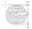
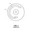
- FIG. 1illustrates a plan view of a magnetic recording media substrate 130 which has been wet cleaned and dried in such a manner during a media fabrication process.
- a residue stain 131is depicted on the magnetic recording media substrate 130 .
- Such stainsare frequently caused by improper drying which may occur for example when the workpiece is pulled, or withdrawn, from the liquid during the drying operation and the liquid meniscus at the liquid interface breaks poorly and leaves behind a residue.
- FIG. 1illustrates a plan view of an annular disk-shaped magnetic recording media which has been wet cleaned and dried in a conventional manner during a media fabrication process
- FIGS. 2A and 2Bare each cross-sectional views, orthogonal to each other, illustrating a dryer module of a wet clean station, in accordance with an embodiment
- FIG. 3is a graph illustrating dryer chamber temperature dependence upon dryer process time and hood door position
- FIG. 4is a plan view of an annular disk-shaped magnetic recording media illustrating workpiece zones upon which pull speed depends, in accordance with an embodiment
- FIG. 5is a flow diagram illustrating a method of displacing a workpiece from a liquid volume to gaseous volume, in accordance with an embodiment
- FIG. 6illustrates temperature dependent pull speed lookup tables, in accordance with embodiments.
- FIG. 7is a block diagram illustrating a control system for displacing a workpiece from a liquid volume to gaseous volume based on temperature of the gaseous volume, in accordance with an embodiment.
- FIGS. 2A and 2Bare orthogonal cross-sectional views illustrating an exemplary dryer module 200 , which may be one module of an automated wet station (AWS) or a stand-alone apparatus.
- a dryer modulesuch as that depicted in FIGS. 2A and 2B is commercially available through Invenpro, (M) Sdn. Bhd. of Malaysia. However, particular embodiments describe herein may nonetheless be practiced with any other commercially available dryer modules which have capabilities similar to those describe herein.
- the dryer module 200includes a tank 201 containing a liquid volume 205 . Over the liquid volume 205 is a gaseous volume 210 which further includes a dryer hood 212 and a dryer chamber 215 .
- the dryer hood 212encloses a high temperature region to rapidly dry the disk while the gaseous volume within the dryer chamber 215 serves as a buffer region between the dryer hood 212 and liquid volume 205 to ensure the gas introduced into the dryer hood 212 does not perturb the liquid-gaseous interface 206 .
- hood doors 214open and close to permit transport of a shuttle 225 carrying at least one workpiece, such as a magnetic recording media substrate 130 , to and from the dryer module 200 by a robot handler 220 .
- a shuttle 225carrying at least one workpiece, such as a magnetic recording media substrate 130
- the hood doors 214open, the magnetic recording media substrate 130 is submerged in the liquid volume 205 so that all surfaces of the magnetic recording media substrate 130 are below the liquid-gaseous interface 206 , and the hood doors 214 close.
- the gaseous volume within the dryer hood 212is heated to a controlled setpoint by introducing a gas, such as nitrogen (N 2 ), heated to approximately 80-125° C. Heating of the inlet gas may be controlled based on feedback from a hood temperature sensor 248 .
- N 2nitrogen
- the dryer module 200further includes a temperature sensor 240 positioned proximate to the liquid-gaseous interface 206 for determining the temperature of the dryer chamber 215 .
- the temperature sensor 240is positioned within approximately 50 mm of the liquid-gaseous interface 206 and preferably within approximately 25 mm.
- the temperature sensor 240may be utilized for control of the speed at which the magnetic recording media substrate 130 is pulled from the liquid volume 205 into the gaseous volume 210 , and in particular the dryer chamber 215 , during the drying operation. Controlling the pull speed in this temperature dependent manner enables the drying efficiency to be improved so that workpiece staining and/or total drying time may be shortened, thereby improving dryer throughput.
- the pull speedmay be made dependent both the geometry of the workpiece and on the temperature of the dryer to control meniscus behavior and improve drying efficiency.
- the speed at which a workpiece is displaced out of a liquidis dependent on the geometry of the workpiece.
- the geometry of the workpiecedetermines the surface topologies which pass through the liquid-gaseous interface 206 forming a meniscus.
- the interface meniscusis stronger at higher pull speeds and therefore the pull speed may be relatively lower in zones where the workpiece surface breaks the meniscus.
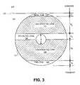
- FIG. 3is an expanded side view of FIG. 2B , depicting the magnetic recording media substrate 130 standing upright within a liquid volume 205 .
- the magnetic recording media substrate 130has an annular disk-shape.
- the outer diameter (OD)varies between approximately 48 mm to 95 mm while the inner diameter (ID) ranges from approximately 20 mm to 25 mm.
- IDinner diameter
- other dimensionsare also possible, depending on the application of the magnetic recording media.
- the magnetic recording media substrate 130includes a magnetic recording layer on the surface of the disk.
- the magnetic layermay be of any known composition, such as a cobalt (Co) alloy.
- the magnetic layermay be formed on both sides of magnetic recording media substrate 130 to form a double-sided magnetic recording disk. Alternatively, a single sided perpendicular magnetic recording disk may be formed.
- the magnetic recording media substrate 130may be, for example, a glass material, a metal, and/or a metal alloy material.
- Glass substrates that may be usedinclude, for example, silica containing glass such as borosilicate glass and aluminosilicate glass.
- Metal and metal alloy substrates that may be usedinclude, for example, aluminum (Al) and aluminum magnesium (AlMg) substrates, respectively.
- the magnetic recording media substrate 130may also be plated with a nickel phosphorous (NiP) layer.
- workpiece zones 332 , 333 , 334 , 335 and 336pass through the liquid-gaseous interface 206 as a robot handler traverses the displacement distances D 1 , D 2 , D 3 , D 4 and D 5 , respectively.
- the pull speed of the robot handlerdepends on positional teach points to define the displacement distances D 1 -D 5 and thereby account for the geometry of magnetic recording media substrate 130 .
- workpiece zones 332 - 336form a pull speed profile across the major surfaces of the magnetic recording media substrate 130 .
- the initial zone 332includes a top OD surface of the magnetic recording media substrate 130 . It has been found that a relatively lower pull speed for the initial zone 332 is advantageous.
- the displacement distance D 1may be between 1 and 10 mm, depending on the substrate OD and ID and is preferably between 4 and 6 mm for a substrate having a 95 mm OD and a 25 mm ID.
- the pull speedmay then be increased to a first intermediate pull speed for the displacement distance D 2 , which may be between 10 mm and 40 mm, depending on the substrate OD and ID and is preferably between 20 mm and 30 mm for a substrate having a 95 mm OD and a 25 mm ID.
- the high speed pull zone 333passes through the liquid-gaseous interface 206 at this first intermediate pull speed. Increasing the pull speed above that used for the initial zone 332 shortens drying time, advantageously increasing dryer throughput.
- the first intermediate pull speedmay be approximately 1.7 mm/s.
- the first intermediate pull speedmay then be reduced to a second intermediate pull speed upon reaching the ID slow pull zone 334 where the meniscus is again broken by the ID surface of the magnetic recording media substrate 130 .
- the transition between the first intermediate pull speed and the second intermediate pull speedoccurs upon the ID surface being submerged approximately 1-5 mm below the liquid-gaseous interface 206 , with the displacement distance D 2 to be maximized and displacement distance D 1 minimized for highest throughput.
- the ID slow pull zone 334extends to approximately one half of the ID.
- the displacement distance D 3is between 15 mm and 20 mm.
- the second intermediate pull speedis approximately 0.7 mm/s.
- the pull speedis then increased to a third intermediate pull speed along the displacement distance D 4 where the high speed pull zone 335 passes through the liquid-gaseous interface 206 .
- the higher third intermediate pull speedfurther improves the dryer throughput and in an advantageous embodiment, the third intermediate pull speed is greater than first intermediate pull speed.
- the displacement distance D 4again depends on the substrate OD and ID and is preferably between 20 mm and 30 mm for a substrate having a 95 mm OD and a 25 mm ID. In one exemplary embodiment, the third intermediate pull speed is approximately 1.7 mm/s.
- the pull speedis then reduced from the third intermediate pull speed to a final pull speed as the final zone 336 , including the bottom OD surface of the magnetic recording media substrate 130 , passes through the liquid-gaseous interface 206 over the displacement distance D 5 .
- the displacement distance D 5depends on the substrate OD and ID and is preferably between 5 mm and 10 mm for a substrate having a 95 mm OD and a 25 mm ID.
- the final pull speedis approximately 0.7 mm/s.
- pull speeddepends on the workpiece geometry such that the pull speed is a non-linear function of the displacement of the workpiece.
- the temperature of the gaseous volume within the dryer chamber 215increases by convective heat transfer such that a considerable temperature delta may exist between the dryer hood 212 and dryer chamber 215 .
- the highest temperature T 1is in the dryer hood proximate to the gas inlet 213 with a lowest temperature T 3 , in the chamber proximate to the liquid-gaseous interface 206 at the distal end of tank, furthest from the gas inlet 213 .
- An intermediate temperature T 2may be found in a region of the gaseous volume there between.
- the temperature of the gaseous volume in the dryer chamber 215has a large impact on at least some of the mechanisms responsible for the staining of a workpiece during a drying operation.
- the pull speedmust be lowered to reduce staining.
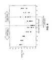
- FIG. 4is a graph illustrating dryer chamber temperature dependence upon time and hood door position during a drying cycle.
- the temperature in the dryer chamber 215e.g., as measured by the temperature sensor 240
- the robot handler 220transports the magnetic recording media substrate 130 through the dryer hood 212 and dryer chamber 215 and submerges the media in the liquid volume 205 .
- the heated N 2is then introduced into the dryer hood 212 .
- the chamber temperaturedoes not. Instead, the temperature within the dryer chamber 215 increases by approximately 30° C. from the 45 second time mark to the 85 second time mark.
- there is significant variatione.g., 15 to 20° C.
- the pull speedmay be increased and the hood drying time reduced.
- the drying which occurs as the workpiece zones pass through the dryer chamber 215becomes more important to the overall drying efficiency.
- the temperature within the dryer chamber 215may still be at a very low temperature (i.e., significantly below the hood temperature) so that drying efficiency within the dryer chamber 215 is poor.
- FIG. 5is a flow diagram illustrating a workpiece pulling method 500 in which a workpiece is displaced from a liquid volume to gaseous volume at a pull speed that is dependent on the temperature of the dryer chamber 215 .
- the pull speedis set by an automated control system executing the workpiece pulling method 500 .
- the workpiece pulling method 500begins at operation 501 with submerging the workpiece in a liquid volume.
- the dryer hood doors 214 closedthe dryer hood 212 is heated toward setpoint, convectively heating the dryer chamber 215 .
- the actual temperature of the dryer chamber 215is measured, for example with the temperature sensor 240 .
- the heating of the dryer hood 212 and sensing of the temperature in the dryer chamber 215is initiated once the magnetic recording media substrate 130 is submerged in the liquid volume 205 .
- the chamber temperaturemay be sensed at any nominal sampling rate, for example one measurement/second.
- a lookup tableis accessed to determine a pull speed based on the sensed chamber temperature.
- Exemplary LUTare depicted in FIG. 6 .
- a temperature dependent pull speed LUT 601includes an array of chamber temperatures, each associated with a maximum pull speed. As depicted, the maximum pull speed decreases with lower chamber temperature. It should be noted however, that the actual values populating the LUT 601 are merely exemplary and the pull speed dependency on chamber temperature may be either a linear or non-linear.
- the maximum pull speed determined at operation 520may then be scaled based on the workpiece zone being displaced through the liquid-gaseous interface. In this manner, the pull speed is made both a function of the chamber temperature and a function of the geometry of the workpiece.
- the temperature dependent pull speed LUT 605may be accessed at operation 520 . As depicted in FIG. 6 , the temperature dependent pull speed LUT 605 includes an array of chamber temperatures and an associated pull speed for each of a number of workpiece zones. The actual values of populating the LUT 605 are merely exemplary. In such an embodiment, a specific pull speed based on both the chamber temperature and the workpiece zone may be determined directly at operation 520 and a secondary scaling of a maximum pull speed is unnecessary.
- the workpiece pulling method 500diverges at operation 525 to allow for a chamber temperature ramp delay if the pull from the liquid has not yet begun. As depicted in FIG. 4 , waiting 20 seconds before displacing the initial workpiece zone (e.g., zone 332 in FIG. 3 ) permits the chamber temperature to increase approximately 15 to 20° C. The higher chamber drying efficiency at the elevated temperature then enables a faster pull speed and potentially a shorter hood drying time. Such a chamber temperature ramp delay entails a later drying start time for the benefit of the greater drying efficiency possible with a higher temperature drying chamber.
- the workpiece pulling method 500returns to operation 510 to again read the actual temperature, thereby delaying a pull of the workpiece from the liquid volume 205 for each iteration of operations 510 - 530 by at least the temperature sample rate until the chamber temperature increases. For example, where operation 510 is performed at a sample rate of approximately one sample/sec, the delay period will be a multiple of the one sample/sec rate. If the chamber temperature is determined to be at or above a minimum temperature threshold at operation 530 , the pull is immediately initiated at operation 540 to displace the initial zone from the liquid volume 205 at the initial pull speed as determined operation 515 . In alternate embodiments, where a temperature ramp delay is avoided, the operation 530 is eliminated and, at operation 540 , the initial pull commences immediately at a speed based on chamber temperature.
- the workpiece pulling method 500returns to operation 510 to again read the chamber temperature, determine the workpiece zone at operation 515 and determine a new pull speed based on the temperature at operation 520 . Because the dryer chamber 215 becomes warmer with time and the workpiece zone has incremented into an intermediate zone, the pull speed determined this time at operation 520 may be considerably higher than it was for the initial workpiece zone.
- the workpiece pulling method 500then continues to operation 525 , and because the pull has been initiated, the workpiece pulling method 500 proceeds this time to operation 545 to begin displacing the next zone (N) from the liquid volume 205 to the gaseous volume (e.g., within dryer chamber 215 ).
- the workpiece pulling method 500then continues to operation 550 , at which point the method diverges. If all workpiece zones have been pulled through the liquid-gaseous interface 206 , the workpiece pulling method 500 completes at operation 560 and the workpiece may then be completely dried within the dryer hood 212 .
- the workpiece pulling method 500repeats the cycle by returning to operation 510 for another chamber temperature sample and another iteration of the operations 515 , 520 , 525 , 545 and 550 .
- the pull speed for any particular zonemay be updated multiple times as the workpiece is displaced through the zone. For example, referring back to FIG. 3 , the first pull speed of approximately 0.7 mm/s for the high speed pull zone 333 may be modified to be approximately 0.8 mm/s upon a second temperature determination.
- the workpiece pulling method 500may be looped in this manner continuously such that the pull speed for each workpiece zone may be maximized as a function of both zone and chamber temperature.
- the pull speeds in the specific geometrically-based workpiece zones depicted in FIG. 3may be adapted to additionally depend on chamber temperature for increased throughput and reduced staining.
- the initial pull speed and first intermediate pull speedare each set based on the temperature of a gaseous volume. For example, over the initial zone 332 , the pull speed may be reduced to approximately 0.75+/ ⁇ 0.25 mm/s, depending on the dryer chamber temperature.
- Such a low, temperature dependent, pull speedwill achieve mush less residual liquid staining on the side of the magnetic recording media substrate 130 , near the top surface.
- the slower initial pull speedwould improve the drying efficiency of the relatively cooler dryer chamber because the poor meniscus behavior is reduced or eliminated by the slower pull speed.
- the total pull durationis not increased greatly because the displacement distance D 1 is small and the pull speed temperature dependence accounts for the significant run-to-run variation in the chamber temperature.
- the pull speed for certain workpiece zonesis modified to compensate for a relatively slower pull speed in other workpiece zones dictated by the lower dryer temperature.
- the pull speed in a second workpiece zoneis made dependent on the pull speed of a first workpiece zone. For example, where the pull speed in a first workpiece zone is temperature dependent and performed at a rate relatively lower than a nominal value, the pull speed in a second workpiece zone, which may not be temperature dependent (e.g., one of the intermediate zones, such as high speed pull zones 333 or 335 ), is increased to compensate (based on displacement distance and pull rate) toward a nominal total pull duration.
- the pull speed at each of the five depicted workpiece zones 332 - 336is determined based on the dryer chamber temperature. Such an embodiment incurs little additional implementation overhead and additional throughput gains may be achieved by increasing the pull speed in other workpiece zones.
- the third intermediate pull speed, at which the high speed pull zone 335 passes through the liquid-gaseous interface 206may be increased to approximately 1.75-2.0 mm/s based on the measured chamber temperature.
- the final pull speed(e.g., displacing final zone 336 through the liquid-gaseous interface 206 ) is set to be higher than the initial pull speed.
- the initial pull speedmay vary as approximately 0.75+/ ⁇ 0.25 mm/s because the initial pull speed may be limited by both the lower chamber temperature and the meniscus issues pertaining to the top OD surface while the final pull speed is only limited by the meniscus issues pertaining to the bottom OD surface.
- the final zone 336 including the bottom surface of the magnetic recording media substrate 130passes through the liquid-gaseous interface 206 at a final pull speed that is faster than the second intermediate pull speed, at which the ID slow pull zone 334 passes through liquid-gaseous interface 206 .
- the second intermediate pull speedis approximately 0.5 mm/s.
- FIG. 7is a block diagram illustrating a dryer control system 700 for displacing a workpiece from a liquid volume to gaseous volume at a pull speed dependent on the temperature of the gaseous volume, in accordance with an exemplary embodiment.
- a dryer controller 701such as a programmable logic controller (PLC)
- PLCprogrammable logic controller
- the dryer controller 701is an automated control system responsible for controlling pulling of a workpiece from a liquid volume into a gaseous volume to dry the workpiece, such as that described in reference to FIG. 5 .
- the memory 705may be of any conventional type, such as non-volatile memory (flash, etc.).
- the memory 705stores a temperature based pull speed LUT 601 , as described elsewhere herein.
- the memory 705stores an additional displacement based pull speed LUT 710 including at least one robot positioning teach point associated with a particular nominal pull speed which may be used as a scaling factor for determining a temperature-based, zone-based pull speed.
- the dryer control systemincludes a chamber temperature sensor 240 which is coupled to the dryer controller 701 through I/O 715 and is to provide chamber temperatures 717 to the dryer controller 701 .
- the dryer controllersends a pull speed setpoint 718 to a robot controller 720 .
- I/O 715may further interface with other dryer subsystems, such as a heater controller, liquid level controller, hood door controller (not depicted).
- the robot controller 720Based on the pull speed setpoint 718 , the robot controller 720 sends a motor command 722 to a robot motor 730 .
- the robot controller 720controls the robot motor 730 to the pull speed setpoint 718 based on motor position and/or motor speed feedback received from the robot position sensor 735 .
Landscapes
- Engineering & Computer Science (AREA)
- Physics & Mathematics (AREA)
- Condensed Matter Physics & Semiconductors (AREA)
- General Physics & Mathematics (AREA)
- Manufacturing & Machinery (AREA)
- Computer Hardware Design (AREA)
- Microelectronics & Electronic Packaging (AREA)
- Power Engineering (AREA)
- Drying Of Solid Materials (AREA)
Abstract
Description
Claims (18)
Priority Applications (1)
| Application Number | Priority Date | Filing Date | Title |
|---|---|---|---|
| US12/354,677US8002901B1 (en) | 2009-01-15 | 2009-01-15 | Temperature dependent pull speeds for drying of a wet cleaned workpiece |
Applications Claiming Priority (1)
| Application Number | Priority Date | Filing Date | Title |
|---|---|---|---|
| US12/354,677US8002901B1 (en) | 2009-01-15 | 2009-01-15 | Temperature dependent pull speeds for drying of a wet cleaned workpiece |
Publications (1)
| Publication Number | Publication Date |
|---|---|
| US8002901B1true US8002901B1 (en) | 2011-08-23 |
Family
ID=44455374
Family Applications (1)
| Application Number | Title | Priority Date | Filing Date |
|---|---|---|---|
| US12/354,677Expired - Fee RelatedUS8002901B1 (en) | 2009-01-15 | 2009-01-15 | Temperature dependent pull speeds for drying of a wet cleaned workpiece |
Country Status (1)
| Country | Link |
|---|---|
| US (1) | US8002901B1 (en) |
Cited By (67)
| Publication number | Priority date | Publication date | Assignee | Title |
|---|---|---|---|---|
| US8828566B2 (en) | 2010-05-21 | 2014-09-09 | Wd Media (Singapore) Pte. Ltd. | Perpendicular magnetic recording disc |
| US8859118B2 (en) | 2010-01-08 | 2014-10-14 | Wd Media (Singapore) Pte. Ltd. | Perpendicular magnetic recording medium |
| US8867322B1 (en) | 2013-05-07 | 2014-10-21 | WD Media, LLC | Systems and methods for providing thermal barrier bilayers for heat assisted magnetic recording media |
| US8877359B2 (en) | 2008-12-05 | 2014-11-04 | Wd Media (Singapore) Pte. Ltd. | Magnetic disk and method for manufacturing same |
| US8908315B2 (en) | 2010-03-29 | 2014-12-09 | Wd Media (Singapore) Pte. Ltd. | Evaluation method of magnetic disk, manufacturing method of magnetic disk, and magnetic disk |
| US8941950B2 (en) | 2012-05-23 | 2015-01-27 | WD Media, LLC | Underlayers for heat assisted magnetic recording (HAMR) media |
| US8947987B1 (en) | 2013-05-03 | 2015-02-03 | WD Media, LLC | Systems and methods for providing capping layers for heat assisted magnetic recording media |
| US8951651B2 (en) | 2010-05-28 | 2015-02-10 | Wd Media (Singapore) Pte. Ltd. | Perpendicular magnetic recording disk |
| US8980076B1 (en) | 2009-05-26 | 2015-03-17 | WD Media, LLC | Electro-deposited passivation coatings for patterned media |
| US8995078B1 (en) | 2014-09-25 | 2015-03-31 | WD Media, LLC | Method of testing a head for contamination |
| US8993134B2 (en) | 2012-06-29 | 2015-03-31 | Western Digital Technologies, Inc. | Electrically conductive underlayer to grow FePt granular media with (001) texture on glass substrates |
| US9001630B1 (en) | 2011-03-08 | 2015-04-07 | Western Digital Technologies, Inc. | Energy assisted magnetic recording medium capable of suppressing high DC readback noise |
| US9005782B2 (en) | 2008-03-30 | 2015-04-14 | WD Media, LLC | Magnetic disk and method of manufacturing the same |
| US9025264B1 (en) | 2011-03-10 | 2015-05-05 | WD Media, LLC | Methods for measuring media performance associated with adjacent track interference |
| US9029308B1 (en) | 2012-03-28 | 2015-05-12 | WD Media, LLC | Low foam media cleaning detergent |
| US9028985B2 (en) | 2011-03-31 | 2015-05-12 | WD Media, LLC | Recording media with multiple exchange coupled magnetic layers |
| US9034492B1 (en) | 2013-01-11 | 2015-05-19 | WD Media, LLC | Systems and methods for controlling damping of magnetic media for heat assisted magnetic recording |
| US9042053B1 (en) | 2014-06-24 | 2015-05-26 | WD Media, LLC | Thermally stabilized perpendicular magnetic recording medium |
| US9047880B1 (en) | 2011-12-20 | 2015-06-02 | WD Media, LLC | Heat assisted magnetic recording method for media having moment keeper layer |
| US9047903B2 (en) | 2008-03-26 | 2015-06-02 | Wd Media (Singapore) Pte. Ltd. | Perpendicular magnetic recording medium and process for manufacture thereof |
| US9064521B1 (en) | 2011-03-25 | 2015-06-23 | WD Media, LLC | Manufacturing of hard masks for patterning magnetic media |
| US9082447B1 (en) | 2014-09-22 | 2015-07-14 | WD Media, LLC | Determining storage media substrate material type |
| US9093122B1 (en) | 2013-04-05 | 2015-07-28 | WD Media, LLC | Systems and methods for improving accuracy of test measurements involving aggressor tracks written to disks of hard disk drives |
| US9093100B2 (en) | 2008-03-17 | 2015-07-28 | Wd Media (Singapore) Pte. Ltd. | Magnetic recording medium including tailored exchange coupling layer and manufacturing method of the same |
| US9142241B2 (en) | 2009-03-30 | 2015-09-22 | Wd Media (Singapore) Pte. Ltd. | Perpendicular magnetic recording medium and method of manufacturing the same |
| US9153268B1 (en) | 2013-02-19 | 2015-10-06 | WD Media, LLC | Lubricants comprising fluorinated graphene nanoribbons for magnetic recording media structure |
| US9159350B1 (en) | 2014-07-02 | 2015-10-13 | WD Media, LLC | High damping cap layer for magnetic recording media |
| US9177586B2 (en) | 2008-09-30 | 2015-11-03 | WD Media (Singapore), LLC | Magnetic disk and manufacturing method thereof |
| US9177585B1 (en) | 2013-10-23 | 2015-11-03 | WD Media, LLC | Magnetic media capable of improving magnetic properties and thermal management for heat-assisted magnetic recording |
| US9183867B1 (en) | 2013-02-21 | 2015-11-10 | WD Media, LLC | Systems and methods for forming implanted capping layers in magnetic media for magnetic recording |
| US9190094B2 (en) | 2013-04-04 | 2015-11-17 | Western Digital (Fremont) | Perpendicular recording media with grain isolation initiation layer and exchange breaking layer for signal-to-noise ratio enhancement |
| US9196283B1 (en) | 2013-03-13 | 2015-11-24 | Western Digital (Fremont), Llc | Method for providing a magnetic recording transducer using a chemical buffer |
| US9218850B1 (en) | 2014-12-23 | 2015-12-22 | WD Media, LLC | Exchange break layer for heat-assisted magnetic recording media |
| US9227324B1 (en) | 2014-09-25 | 2016-01-05 | WD Media, LLC | Mandrel for substrate transport system with notch |
| US9240204B2 (en) | 2010-05-21 | 2016-01-19 | Wd Media (Singapore) Pte. Ltd. | Perpendicular magnetic recording disc |
| US9257134B1 (en) | 2014-12-24 | 2016-02-09 | Western Digital Technologies, Inc. | Allowing fast data zone switches on data storage devices |
| US9269480B1 (en) | 2012-03-30 | 2016-02-23 | WD Media, LLC | Systems and methods for forming magnetic recording media with improved grain columnar growth for energy assisted magnetic recording |
| US9275669B1 (en) | 2015-03-31 | 2016-03-01 | WD Media, LLC | TbFeCo in PMR media for SNR improvement |
| US9280998B1 (en) | 2015-03-30 | 2016-03-08 | WD Media, LLC | Acidic post-sputter wash for magnetic recording media |
| US9296082B1 (en) | 2013-06-11 | 2016-03-29 | WD Media, LLC | Disk buffing apparatus with abrasive tape loading pad having a vibration absorbing layer |
| US9330685B1 (en) | 2009-11-06 | 2016-05-03 | WD Media, LLC | Press system for nano-imprinting of recording media with a two step pressing method |
| US9339978B1 (en) | 2009-11-06 | 2016-05-17 | WD Media, LLC | Press system with interleaved embossing foil holders for nano-imprinting of recording media |
| US9349404B2 (en) | 2010-05-28 | 2016-05-24 | Wd Media (Singapore) Pte. Ltd | Perpendicular magnetic recording disc |
| US9382496B1 (en) | 2013-12-19 | 2016-07-05 | Western Digital Technologies, Inc. | Lubricants with high thermal stability for heat-assisted magnetic recording |
| US9389135B2 (en) | 2013-09-26 | 2016-07-12 | WD Media, LLC | Systems and methods for calibrating a load cell of a disk burnishing machine |
| US9401300B1 (en) | 2014-12-18 | 2016-07-26 | WD Media, LLC | Media substrate gripper including a plurality of snap-fit fingers |
| US9406330B1 (en) | 2013-06-19 | 2016-08-02 | WD Media, LLC | Method for HDD disk defect source detection |
| US9406329B1 (en) | 2015-11-30 | 2016-08-02 | WD Media, LLC | HAMR media structure with intermediate layer underlying a magnetic recording layer having multiple sublayers |
| US9431045B1 (en) | 2014-04-25 | 2016-08-30 | WD Media, LLC | Magnetic seed layer used with an unbalanced soft underlayer |
| US9449633B1 (en) | 2014-11-06 | 2016-09-20 | WD Media, LLC | Smooth structures for heat-assisted magnetic recording media |
| US9447368B1 (en) | 2014-02-18 | 2016-09-20 | WD Media, LLC | Detergent composition with low foam and high nickel solubility |
| US9472227B2 (en) | 2010-06-22 | 2016-10-18 | Wd Media (Singapore) Pte. Ltd. | Perpendicular magnetic recording media and methods for producing the same |
| US9542968B1 (en) | 2010-08-20 | 2017-01-10 | WD Media, LLC | Single layer small grain size FePT:C film for heat assisted magnetic recording media |
| US9558778B2 (en) | 2009-03-28 | 2017-01-31 | Wd Media (Singapore) Pte. Ltd. | Lubricant compound for magnetic disk and magnetic disk |
| US9581510B1 (en) | 2013-12-16 | 2017-02-28 | Western Digital Technologies, Inc. | Sputter chamber pressure gauge with vibration absorber |
| US9607646B2 (en) | 2013-07-30 | 2017-03-28 | WD Media, LLC | Hard disk double lubrication layer |
| US9685184B1 (en) | 2014-09-25 | 2017-06-20 | WD Media, LLC | NiFeX-based seed layer for magnetic recording media |
| US9818442B2 (en) | 2014-12-01 | 2017-11-14 | WD Media, LLC | Magnetic media having improved magnetic grain size distribution and intergranular segregation |
| US9822441B2 (en) | 2015-03-31 | 2017-11-21 | WD Media, LLC | Iridium underlayer for heat assisted magnetic recording media |
| US9824711B1 (en) | 2014-02-14 | 2017-11-21 | WD Media, LLC | Soft underlayer for heat assisted magnetic recording media |
| US9990940B1 (en) | 2014-12-30 | 2018-06-05 | WD Media, LLC | Seed structure for perpendicular magnetic recording media |
| US10054363B2 (en) | 2014-08-15 | 2018-08-21 | WD Media, LLC | Method and apparatus for cryogenic dynamic cooling |
| US10083715B2 (en) | 2010-05-28 | 2018-09-25 | WD Media (Singapore) Pte.Ltd. | Method of manufacturing a perpendicular magnetic disc |
| US10115428B1 (en) | 2013-02-15 | 2018-10-30 | Wd Media, Inc. | HAMR media structure having an anisotropic thermal barrier layer |
| US10121506B1 (en) | 2015-12-29 | 2018-11-06 | WD Media, LLC | Magnetic-recording medium including a carbon overcoat implanted with nitrogen and hydrogen |
| US10236026B1 (en) | 2015-11-06 | 2019-03-19 | WD Media, LLC | Thermal barrier layers and seed layers for control of thermal and structural properties of HAMR media |
| US11074934B1 (en) | 2015-09-25 | 2021-07-27 | Western Digital Technologies, Inc. | Heat assisted magnetic recording (HAMR) media with Curie temperature reduction layer |
Citations (24)
| Publication number | Priority date | Publication date | Assignee | Title |
|---|---|---|---|---|
| US4736760A (en) | 1986-02-21 | 1988-04-12 | Robert A. Coberly | Apparatus for cleaning, rinsing and drying substrates |
| US4902350A (en) | 1987-09-09 | 1990-02-20 | Robert F. Orr | Method for rinsing, cleaning and drying silicon wafers |
| US4984597A (en) | 1984-05-21 | 1991-01-15 | Cfm Technologies Research Associates | Apparatus for rinsing and drying surfaces |
| US5301701A (en) | 1992-07-30 | 1994-04-12 | Nafziger Charles P | Single-chamber cleaning, rinsing and drying apparatus and method therefor |
| US5653045A (en) | 1995-06-07 | 1997-08-05 | Ferrell; Gary W. | Method and apparatus for drying parts and microelectronic components using sonic created mist |
| US5660642A (en) | 1995-05-26 | 1997-08-26 | The Regents Of The University Of California | Moving zone Marangoni drying of wet objects using naturally evaporated solvent vapor |
| US5671544A (en) | 1993-10-29 | 1997-09-30 | Tokyo Electron Limited | Substrate drying apparatus and substrate drying method |
| US5727578A (en) | 1993-07-16 | 1998-03-17 | Legacy Systems, Inc. | Apparatus for the treatment and drying of semiconductor wafers in a fluid |
| US5776259A (en) | 1993-04-02 | 1998-07-07 | National Semiconductor Corporation | Method for final rinse/dry for critical cleaning application |
| US5849104A (en) | 1996-09-19 | 1998-12-15 | Yieldup International | Method and apparatus for cleaning wafers using multiple tanks |
| US5985041A (en) | 1998-03-05 | 1999-11-16 | Micron Technology, Inc. | Method of rinsing and drying semiconductor wafers in a chamber with a movable side wall |
| US6027574A (en) | 1997-08-07 | 2000-02-22 | Applied Materials, Inc. | Method of drying a substrate by lowering a fluid surface level |
| US6029371A (en) | 1997-09-17 | 2000-02-29 | Tokyo Electron Limited | Drying treatment method and apparatus |
| US6446355B1 (en) | 1999-05-27 | 2002-09-10 | Lam Research Corporation | Disk drying apparatus and method |
| US6620260B2 (en) | 2000-05-15 | 2003-09-16 | Tokyo Electron Limited | Substrate rinsing and drying method |
| US6625901B1 (en) | 1999-05-27 | 2003-09-30 | Oliver Design, Inc. | Apparatus and method for drying a thin substrate |
| US20030234029A1 (en) | 2001-07-16 | 2003-12-25 | Semitool, Inc. | Cleaning and drying a substrate |
| US6928748B2 (en) | 2003-10-16 | 2005-08-16 | Taiwan Semiconductor Manufacturing Co., Ltd | Method to improve post wafer etch cleaning process |
| US6955516B2 (en) | 2001-11-02 | 2005-10-18 | Applied Materials, Inc. | Single wafer dryer and drying methods |
| US20050229426A1 (en)* | 2001-11-02 | 2005-10-20 | Applied Materials, Inc. | Single wafer dryer and drying methods |
| US7252098B2 (en) | 1999-03-26 | 2007-08-07 | Applied Materials, Inc. | Apparatus for cleaning and drying substrates |
| US20070181159A1 (en) | 2006-02-03 | 2007-08-09 | Hitachi High-Technologies Corporation | Disk cleaning apparatus, disk immersing and extracting mechanism and disk cleaning method |
| WO2008056969A1 (en) | 2006-11-09 | 2008-05-15 | Invenpro (M) Sdn. Bhd. | Method for drying a substrate |
| US7437832B2 (en) | 2004-11-29 | 2008-10-21 | Seiko Epson Corporation | Reduced pressure drying apparatus |
- 2009
- 2009-01-15USUS12/354,677patent/US8002901B1/ennot_activeExpired - Fee Related
Patent Citations (26)
| Publication number | Priority date | Publication date | Assignee | Title |
|---|---|---|---|---|
| US4984597A (en) | 1984-05-21 | 1991-01-15 | Cfm Technologies Research Associates | Apparatus for rinsing and drying surfaces |
| US4984597B1 (en) | 1984-05-21 | 1999-10-26 | Cfmt Inc | Apparatus for rinsing and drying surfaces |
| US4736760A (en) | 1986-02-21 | 1988-04-12 | Robert A. Coberly | Apparatus for cleaning, rinsing and drying substrates |
| US4902350A (en) | 1987-09-09 | 1990-02-20 | Robert F. Orr | Method for rinsing, cleaning and drying silicon wafers |
| US5301701A (en) | 1992-07-30 | 1994-04-12 | Nafziger Charles P | Single-chamber cleaning, rinsing and drying apparatus and method therefor |
| US5776259A (en) | 1993-04-02 | 1998-07-07 | National Semiconductor Corporation | Method for final rinse/dry for critical cleaning application |
| US5727578A (en) | 1993-07-16 | 1998-03-17 | Legacy Systems, Inc. | Apparatus for the treatment and drying of semiconductor wafers in a fluid |
| US5671544A (en) | 1993-10-29 | 1997-09-30 | Tokyo Electron Limited | Substrate drying apparatus and substrate drying method |
| US5660642A (en) | 1995-05-26 | 1997-08-26 | The Regents Of The University Of California | Moving zone Marangoni drying of wet objects using naturally evaporated solvent vapor |
| US5653045A (en) | 1995-06-07 | 1997-08-05 | Ferrell; Gary W. | Method and apparatus for drying parts and microelectronic components using sonic created mist |
| US5849104A (en) | 1996-09-19 | 1998-12-15 | Yieldup International | Method and apparatus for cleaning wafers using multiple tanks |
| US6027574A (en) | 1997-08-07 | 2000-02-22 | Applied Materials, Inc. | Method of drying a substrate by lowering a fluid surface level |
| US6029371A (en) | 1997-09-17 | 2000-02-29 | Tokyo Electron Limited | Drying treatment method and apparatus |
| US5985041A (en) | 1998-03-05 | 1999-11-16 | Micron Technology, Inc. | Method of rinsing and drying semiconductor wafers in a chamber with a movable side wall |
| US7252098B2 (en) | 1999-03-26 | 2007-08-07 | Applied Materials, Inc. | Apparatus for cleaning and drying substrates |
| US6446355B1 (en) | 1999-05-27 | 2002-09-10 | Lam Research Corporation | Disk drying apparatus and method |
| US6615510B2 (en) | 1999-05-27 | 2003-09-09 | Lam Research Corporation | Wafer drying apparatus and method |
| US6625901B1 (en) | 1999-05-27 | 2003-09-30 | Oliver Design, Inc. | Apparatus and method for drying a thin substrate |
| US6620260B2 (en) | 2000-05-15 | 2003-09-16 | Tokyo Electron Limited | Substrate rinsing and drying method |
| US20030234029A1 (en) | 2001-07-16 | 2003-12-25 | Semitool, Inc. | Cleaning and drying a substrate |
| US6955516B2 (en) | 2001-11-02 | 2005-10-18 | Applied Materials, Inc. | Single wafer dryer and drying methods |
| US20050229426A1 (en)* | 2001-11-02 | 2005-10-20 | Applied Materials, Inc. | Single wafer dryer and drying methods |
| US6928748B2 (en) | 2003-10-16 | 2005-08-16 | Taiwan Semiconductor Manufacturing Co., Ltd | Method to improve post wafer etch cleaning process |
| US7437832B2 (en) | 2004-11-29 | 2008-10-21 | Seiko Epson Corporation | Reduced pressure drying apparatus |
| US20070181159A1 (en) | 2006-02-03 | 2007-08-09 | Hitachi High-Technologies Corporation | Disk cleaning apparatus, disk immersing and extracting mechanism and disk cleaning method |
| WO2008056969A1 (en) | 2006-11-09 | 2008-05-15 | Invenpro (M) Sdn. Bhd. | Method for drying a substrate |
Cited By (69)
| Publication number | Priority date | Publication date | Assignee | Title |
|---|---|---|---|---|
| US9093100B2 (en) | 2008-03-17 | 2015-07-28 | Wd Media (Singapore) Pte. Ltd. | Magnetic recording medium including tailored exchange coupling layer and manufacturing method of the same |
| US9047903B2 (en) | 2008-03-26 | 2015-06-02 | Wd Media (Singapore) Pte. Ltd. | Perpendicular magnetic recording medium and process for manufacture thereof |
| US9005782B2 (en) | 2008-03-30 | 2015-04-14 | WD Media, LLC | Magnetic disk and method of manufacturing the same |
| US9177586B2 (en) | 2008-09-30 | 2015-11-03 | WD Media (Singapore), LLC | Magnetic disk and manufacturing method thereof |
| US9984715B2 (en) | 2008-09-30 | 2018-05-29 | WD Media, LLC | Magnetic disk and manufacturing method thereof |
| US8877359B2 (en) | 2008-12-05 | 2014-11-04 | Wd Media (Singapore) Pte. Ltd. | Magnetic disk and method for manufacturing same |
| US9558778B2 (en) | 2009-03-28 | 2017-01-31 | Wd Media (Singapore) Pte. Ltd. | Lubricant compound for magnetic disk and magnetic disk |
| US9142241B2 (en) | 2009-03-30 | 2015-09-22 | Wd Media (Singapore) Pte. Ltd. | Perpendicular magnetic recording medium and method of manufacturing the same |
| US8980076B1 (en) | 2009-05-26 | 2015-03-17 | WD Media, LLC | Electro-deposited passivation coatings for patterned media |
| US9330685B1 (en) | 2009-11-06 | 2016-05-03 | WD Media, LLC | Press system for nano-imprinting of recording media with a two step pressing method |
| US9339978B1 (en) | 2009-11-06 | 2016-05-17 | WD Media, LLC | Press system with interleaved embossing foil holders for nano-imprinting of recording media |
| US8859118B2 (en) | 2010-01-08 | 2014-10-14 | Wd Media (Singapore) Pte. Ltd. | Perpendicular magnetic recording medium |
| US8908315B2 (en) | 2010-03-29 | 2014-12-09 | Wd Media (Singapore) Pte. Ltd. | Evaluation method of magnetic disk, manufacturing method of magnetic disk, and magnetic disk |
| US8828566B2 (en) | 2010-05-21 | 2014-09-09 | Wd Media (Singapore) Pte. Ltd. | Perpendicular magnetic recording disc |
| US9240204B2 (en) | 2010-05-21 | 2016-01-19 | Wd Media (Singapore) Pte. Ltd. | Perpendicular magnetic recording disc |
| US8951651B2 (en) | 2010-05-28 | 2015-02-10 | Wd Media (Singapore) Pte. Ltd. | Perpendicular magnetic recording disk |
| US10083715B2 (en) | 2010-05-28 | 2018-09-25 | WD Media (Singapore) Pte.Ltd. | Method of manufacturing a perpendicular magnetic disc |
| US9349404B2 (en) | 2010-05-28 | 2016-05-24 | Wd Media (Singapore) Pte. Ltd | Perpendicular magnetic recording disc |
| US9472227B2 (en) | 2010-06-22 | 2016-10-18 | Wd Media (Singapore) Pte. Ltd. | Perpendicular magnetic recording media and methods for producing the same |
| US9542968B1 (en) | 2010-08-20 | 2017-01-10 | WD Media, LLC | Single layer small grain size FePT:C film for heat assisted magnetic recording media |
| US9001630B1 (en) | 2011-03-08 | 2015-04-07 | Western Digital Technologies, Inc. | Energy assisted magnetic recording medium capable of suppressing high DC readback noise |
| US9025264B1 (en) | 2011-03-10 | 2015-05-05 | WD Media, LLC | Methods for measuring media performance associated with adjacent track interference |
| US9064521B1 (en) | 2011-03-25 | 2015-06-23 | WD Media, LLC | Manufacturing of hard masks for patterning magnetic media |
| US9028985B2 (en) | 2011-03-31 | 2015-05-12 | WD Media, LLC | Recording media with multiple exchange coupled magnetic layers |
| US9047880B1 (en) | 2011-12-20 | 2015-06-02 | WD Media, LLC | Heat assisted magnetic recording method for media having moment keeper layer |
| US9029308B1 (en) | 2012-03-28 | 2015-05-12 | WD Media, LLC | Low foam media cleaning detergent |
| US9269480B1 (en) | 2012-03-30 | 2016-02-23 | WD Media, LLC | Systems and methods for forming magnetic recording media with improved grain columnar growth for energy assisted magnetic recording |
| US8941950B2 (en) | 2012-05-23 | 2015-01-27 | WD Media, LLC | Underlayers for heat assisted magnetic recording (HAMR) media |
| US8993134B2 (en) | 2012-06-29 | 2015-03-31 | Western Digital Technologies, Inc. | Electrically conductive underlayer to grow FePt granular media with (001) texture on glass substrates |
| US9034492B1 (en) | 2013-01-11 | 2015-05-19 | WD Media, LLC | Systems and methods for controlling damping of magnetic media for heat assisted magnetic recording |
| US10115428B1 (en) | 2013-02-15 | 2018-10-30 | Wd Media, Inc. | HAMR media structure having an anisotropic thermal barrier layer |
| US9153268B1 (en) | 2013-02-19 | 2015-10-06 | WD Media, LLC | Lubricants comprising fluorinated graphene nanoribbons for magnetic recording media structure |
| US9183867B1 (en) | 2013-02-21 | 2015-11-10 | WD Media, LLC | Systems and methods for forming implanted capping layers in magnetic media for magnetic recording |
| US9196283B1 (en) | 2013-03-13 | 2015-11-24 | Western Digital (Fremont), Llc | Method for providing a magnetic recording transducer using a chemical buffer |
| US9190094B2 (en) | 2013-04-04 | 2015-11-17 | Western Digital (Fremont) | Perpendicular recording media with grain isolation initiation layer and exchange breaking layer for signal-to-noise ratio enhancement |
| US9093122B1 (en) | 2013-04-05 | 2015-07-28 | WD Media, LLC | Systems and methods for improving accuracy of test measurements involving aggressor tracks written to disks of hard disk drives |
| US8947987B1 (en) | 2013-05-03 | 2015-02-03 | WD Media, LLC | Systems and methods for providing capping layers for heat assisted magnetic recording media |
| US8867322B1 (en) | 2013-05-07 | 2014-10-21 | WD Media, LLC | Systems and methods for providing thermal barrier bilayers for heat assisted magnetic recording media |
| US9296082B1 (en) | 2013-06-11 | 2016-03-29 | WD Media, LLC | Disk buffing apparatus with abrasive tape loading pad having a vibration absorbing layer |
| US9406330B1 (en) | 2013-06-19 | 2016-08-02 | WD Media, LLC | Method for HDD disk defect source detection |
| US9607646B2 (en) | 2013-07-30 | 2017-03-28 | WD Media, LLC | Hard disk double lubrication layer |
| US9389135B2 (en) | 2013-09-26 | 2016-07-12 | WD Media, LLC | Systems and methods for calibrating a load cell of a disk burnishing machine |
| US9177585B1 (en) | 2013-10-23 | 2015-11-03 | WD Media, LLC | Magnetic media capable of improving magnetic properties and thermal management for heat-assisted magnetic recording |
| US9581510B1 (en) | 2013-12-16 | 2017-02-28 | Western Digital Technologies, Inc. | Sputter chamber pressure gauge with vibration absorber |
| US9382496B1 (en) | 2013-12-19 | 2016-07-05 | Western Digital Technologies, Inc. | Lubricants with high thermal stability for heat-assisted magnetic recording |
| US9824711B1 (en) | 2014-02-14 | 2017-11-21 | WD Media, LLC | Soft underlayer for heat assisted magnetic recording media |
| US9447368B1 (en) | 2014-02-18 | 2016-09-20 | WD Media, LLC | Detergent composition with low foam and high nickel solubility |
| US9431045B1 (en) | 2014-04-25 | 2016-08-30 | WD Media, LLC | Magnetic seed layer used with an unbalanced soft underlayer |
| US9042053B1 (en) | 2014-06-24 | 2015-05-26 | WD Media, LLC | Thermally stabilized perpendicular magnetic recording medium |
| US9159350B1 (en) | 2014-07-02 | 2015-10-13 | WD Media, LLC | High damping cap layer for magnetic recording media |
| US10054363B2 (en) | 2014-08-15 | 2018-08-21 | WD Media, LLC | Method and apparatus for cryogenic dynamic cooling |
| US9082447B1 (en) | 2014-09-22 | 2015-07-14 | WD Media, LLC | Determining storage media substrate material type |
| US9227324B1 (en) | 2014-09-25 | 2016-01-05 | WD Media, LLC | Mandrel for substrate transport system with notch |
| US8995078B1 (en) | 2014-09-25 | 2015-03-31 | WD Media, LLC | Method of testing a head for contamination |
| US9685184B1 (en) | 2014-09-25 | 2017-06-20 | WD Media, LLC | NiFeX-based seed layer for magnetic recording media |
| US9449633B1 (en) | 2014-11-06 | 2016-09-20 | WD Media, LLC | Smooth structures for heat-assisted magnetic recording media |
| US10783915B2 (en) | 2014-12-01 | 2020-09-22 | Western Digital Technologies, Inc. | Magnetic media having improved magnetic grain size distribution and intergranular segregation |
| US9818442B2 (en) | 2014-12-01 | 2017-11-14 | WD Media, LLC | Magnetic media having improved magnetic grain size distribution and intergranular segregation |
| US9401300B1 (en) | 2014-12-18 | 2016-07-26 | WD Media, LLC | Media substrate gripper including a plurality of snap-fit fingers |
| US9218850B1 (en) | 2014-12-23 | 2015-12-22 | WD Media, LLC | Exchange break layer for heat-assisted magnetic recording media |
| US9257134B1 (en) | 2014-12-24 | 2016-02-09 | Western Digital Technologies, Inc. | Allowing fast data zone switches on data storage devices |
| US9990940B1 (en) | 2014-12-30 | 2018-06-05 | WD Media, LLC | Seed structure for perpendicular magnetic recording media |
| US9280998B1 (en) | 2015-03-30 | 2016-03-08 | WD Media, LLC | Acidic post-sputter wash for magnetic recording media |
| US9275669B1 (en) | 2015-03-31 | 2016-03-01 | WD Media, LLC | TbFeCo in PMR media for SNR improvement |
| US9822441B2 (en) | 2015-03-31 | 2017-11-21 | WD Media, LLC | Iridium underlayer for heat assisted magnetic recording media |
| US11074934B1 (en) | 2015-09-25 | 2021-07-27 | Western Digital Technologies, Inc. | Heat assisted magnetic recording (HAMR) media with Curie temperature reduction layer |
| US10236026B1 (en) | 2015-11-06 | 2019-03-19 | WD Media, LLC | Thermal barrier layers and seed layers for control of thermal and structural properties of HAMR media |
| US9406329B1 (en) | 2015-11-30 | 2016-08-02 | WD Media, LLC | HAMR media structure with intermediate layer underlying a magnetic recording layer having multiple sublayers |
| US10121506B1 (en) | 2015-12-29 | 2018-11-06 | WD Media, LLC | Magnetic-recording medium including a carbon overcoat implanted with nitrogen and hydrogen |
Similar Documents
| Publication | Publication Date | Title |
|---|---|---|
| US8002901B1 (en) | Temperature dependent pull speeds for drying of a wet cleaned workpiece | |
| KR101177170B1 (en) | Substrate treating apparatus and method of preventing particle adhesion | |
| TWI505366B (en) | Substrate processing device and substrate processing method thereof | |
| US6796795B2 (en) | Method and apparatus for loading substrate in semiconductor manufacturing apparatus | |
| TWI668764B (en) | Substrate processing device, method for manufacturing semiconductor device, and recording medium | |
| US11177143B2 (en) | Substrate processing apparatus, method of manufacturing semiconductor device, and recording medium | |
| KR20110071125A (en) | Method and apparatus for rapid reactive thermal control in plasma processing apparatus | |
| TWI759650B (en) | Heat treatment device and heat treatment method | |
| CN111095517B (en) | Substrate processing apparatus, method for manufacturing semiconductor device, and storage medium | |
| JP2012506128A5 (en) | ||
| CN101378856A (en) | Method for cooling steel sheet | |
| KR20120113665A (en) | Heat treatment apparatus and heat treatment method | |
| CN101144988A (en) | Temperature gradient controllable wafer front-drying method and its hot plate type front drying device | |
| JP2008266729A (en) | Heating method for steel workpiece | |
| KR102127130B1 (en) | Substrate processing device, manufacturing method and program of semiconductor device | |
| US20110174336A1 (en) | Substrate processing apparatus | |
| US20220310420A1 (en) | Cooling method, a method of manufacturing a semiconductor device and a non-transitory computer-readable recording medium | |
| WO2022070310A1 (en) | Substrate processing device, temperature control program, method for manufacturing semiconductor device, and temperature control method | |
| JP2754972B2 (en) | IC low temperature handling equipment | |
| CN102097314A (en) | Laser heat treatment device and method for accurately controlling cooling process | |
| US12203169B2 (en) | Substrate processing apparatus, method of processing substrate, method of manufacturing semiconductor device and recording medium | |
| JP7574403B2 (en) | Substrate processing apparatus, semiconductor device manufacturing method and program | |
| CN213623845U (en) | Toughened glass cooling device and glass toughening equipment | |
| JP2001093883A (en) | Semiconductor manufacturing device and method therefor | |
| KR200264228Y1 (en) | Process chamber of a rapid thermal processing apparatus |
Legal Events
| Date | Code | Title | Description |
|---|---|---|---|
| AS | Assignment | Owner name:WD MEDIA, INC., CALIFORNIA Free format text:ASSIGNMENT OF ASSIGNORS INTEREST;ASSIGNORS:CHEN, CHAOYUAN;GALLUZI, GEORGE;CHO, JOHN;REEL/FRAME:022535/0598 Effective date:20090116 | |
| STCF | Information on status: patent grant | Free format text:PATENTED CASE | |
| FPAY | Fee payment | Year of fee payment:4 | |
| AS | Assignment | Owner name:JPMORGAN CHASE BANK, N.A., AS COLLATERAL AGENT, ILLINOIS Free format text:SECURITY AGREEMENT;ASSIGNOR:WD MEDIA, LLC;REEL/FRAME:038709/0879 Effective date:20160512 Owner name:U.S. BANK NATIONAL ASSOCIATION, AS COLLATERAL AGENT, CALIFORNIA Free format text:SECURITY AGREEMENT;ASSIGNOR:WD MEDIA, LLC;REEL/FRAME:038709/0931 Effective date:20160512 Owner name:JPMORGAN CHASE BANK, N.A., AS COLLATERAL AGENT, ILLINOIS Free format text:SECURITY AGREEMENT;ASSIGNOR:WD MEDIA, LLC;REEL/FRAME:038710/0383 Effective date:20160512 Owner name:JPMORGAN CHASE BANK, N.A., AS COLLATERAL AGENT, IL Free format text:SECURITY AGREEMENT;ASSIGNOR:WD MEDIA, LLC;REEL/FRAME:038709/0879 Effective date:20160512 Owner name:U.S. BANK NATIONAL ASSOCIATION, AS COLLATERAL AGEN Free format text:SECURITY AGREEMENT;ASSIGNOR:WD MEDIA, LLC;REEL/FRAME:038709/0931 Effective date:20160512 Owner name:JPMORGAN CHASE BANK, N.A., AS COLLATERAL AGENT, IL Free format text:SECURITY AGREEMENT;ASSIGNOR:WD MEDIA, LLC;REEL/FRAME:038710/0383 Effective date:20160512 | |
| AS | Assignment | Owner name:WD MEDIA, LLC, CALIFORNIA Free format text:RELEASE BY SECURED PARTY;ASSIGNOR:U.S. BANK NATIONAL ASSOCIATION, AS COLLATERAL AGENT;REEL/FRAME:045501/0672 Effective date:20180227 | |
| AS | Assignment | Owner name:WD MEDIA, LLC, CALIFORNIA Free format text:CHANGE OF NAME;ASSIGNOR:WD MEDIA, INC;REEL/FRAME:047112/0758 Effective date:20111230 | |
| FEPP | Fee payment procedure | Free format text:MAINTENANCE FEE REMINDER MAILED (ORIGINAL EVENT CODE: REM.); ENTITY STATUS OF PATENT OWNER: LARGE ENTITY | |
| LAPS | Lapse for failure to pay maintenance fees | Free format text:PATENT EXPIRED FOR FAILURE TO PAY MAINTENANCE FEES (ORIGINAL EVENT CODE: EXP.); ENTITY STATUS OF PATENT OWNER: LARGE ENTITY | |
| STCH | Information on status: patent discontinuation | Free format text:PATENT EXPIRED DUE TO NONPAYMENT OF MAINTENANCE FEES UNDER 37 CFR 1.362 | |
| FP | Lapsed due to failure to pay maintenance fee | Effective date:20190823 | |
| AS | Assignment | Owner name:WESTERN DIGITAL TECHNOLOGIES, INC., CALIFORNIA Free format text:RELEASE OF SECURITY INTEREST AT REEL 038710 FRAME 0383;ASSIGNOR:JPMORGAN CHASE BANK, N.A.;REEL/FRAME:058965/0410 Effective date:20220203 Owner name:WD MEDIA, LLC, CALIFORNIA Free format text:RELEASE OF SECURITY INTEREST AT REEL 038710 FRAME 0383;ASSIGNOR:JPMORGAN CHASE BANK, N.A.;REEL/FRAME:058965/0410 Effective date:20220203 |