US8002806B2 - Bottom loading multi-axial screw assembly - Google Patents
Bottom loading multi-axial screw assemblyDownload PDFInfo
- Publication number
- US8002806B2 US8002806B2US11/254,874US25487405AUS8002806B2US 8002806 B2US8002806 B2US 8002806B2US 25487405 AUS25487405 AUS 25487405AUS 8002806 B2US8002806 B2US 8002806B2
- Authority
- US
- United States
- Prior art keywords
- retainer
- head
- anchor member
- distal
- extending
- Prior art date
- Legal status (The legal status is an assumption and is not a legal conclusion. Google has not performed a legal analysis and makes no representation as to the accuracy of the status listed.)
- Active, expires
Links
- 239000007943implantSubstances0.000claimsabstractdescription67
- 210000000988bone and boneAnatomy0.000claimsdescription13
- 238000004891communicationMethods0.000claimsdescription5
- 230000000087stabilizing effectEffects0.000claimsdescription2
- 230000000712assemblyEffects0.000abstractdescription15
- 238000000429assemblyMethods0.000abstractdescription15
- 238000003780insertionMethods0.000description8
- 230000037431insertionEffects0.000description8
- 238000000034methodMethods0.000description6
- 230000006641stabilisationEffects0.000description3
- 238000011105stabilizationMethods0.000description3
- 230000008878couplingEffects0.000description2
- 238000010168coupling processMethods0.000description2
- 238000005859coupling reactionMethods0.000description2
- 230000004927fusionEffects0.000description2
- 238000012986modificationMethods0.000description2
- 230000004048modificationEffects0.000description2
- 230000008569processEffects0.000description2
- 238000001356surgical procedureMethods0.000description2
- 210000001519tissueAnatomy0.000description2
- 239000000853adhesiveSubstances0.000description1
- 230000001070adhesive effectEffects0.000description1
- 230000004075alterationEffects0.000description1
- 210000003484anatomyAnatomy0.000description1
- 238000004873anchoringMethods0.000description1
- 238000013459approachMethods0.000description1
- 238000005452bendingMethods0.000description1
- 230000006835compressionEffects0.000description1
- 238000007906compressionMethods0.000description1
- 238000010586diagramMethods0.000description1
- 230000000694effectsEffects0.000description1
- 238000002513implantationMethods0.000description1
- 210000004705lumbosacral regionAnatomy0.000description1
- 238000002324minimally invasive surgeryMethods0.000description1
- 230000001737promoting effectEffects0.000description1
- 230000009467reductionEffects0.000description1
- 230000000452restraining effectEffects0.000description1
- 230000000717retained effectEffects0.000description1
- 210000000954sacrococcygeal regionAnatomy0.000description1
- 210000000115thoracic cavityAnatomy0.000description1
Images


Classifications
- A—HUMAN NECESSITIES
- A61—MEDICAL OR VETERINARY SCIENCE; HYGIENE
- A61B—DIAGNOSIS; SURGERY; IDENTIFICATION
- A61B17/00—Surgical instruments, devices or methods
- A61B17/56—Surgical instruments or methods for treatment of bones or joints; Devices specially adapted therefor
- A61B17/58—Surgical instruments or methods for treatment of bones or joints; Devices specially adapted therefor for osteosynthesis, e.g. bone plates, screws or setting implements
- A61B17/68—Internal fixation devices, including fasteners and spinal fixators, even if a part thereof projects from the skin
- A61B17/70—Spinal positioners or stabilisers, e.g. stabilisers comprising fluid filler in an implant
- A61B17/7001—Screws or hooks combined with longitudinal elements which do not contact vertebrae
- A61B17/7035—Screws or hooks, wherein a rod-clamping part and a bone-anchoring part can pivot relative to each other
- A61B17/7038—Screws or hooks, wherein a rod-clamping part and a bone-anchoring part can pivot relative to each other to a different extent in different directions, e.g. within one plane only
- A—HUMAN NECESSITIES
- A61—MEDICAL OR VETERINARY SCIENCE; HYGIENE
- A61B—DIAGNOSIS; SURGERY; IDENTIFICATION
- A61B17/00—Surgical instruments, devices or methods
- A—HUMAN NECESSITIES
- A61—MEDICAL OR VETERINARY SCIENCE; HYGIENE
- A61B—DIAGNOSIS; SURGERY; IDENTIFICATION
- A61B17/00—Surgical instruments, devices or methods
- A61B17/56—Surgical instruments or methods for treatment of bones or joints; Devices specially adapted therefor
- A61B17/58—Surgical instruments or methods for treatment of bones or joints; Devices specially adapted therefor for osteosynthesis, e.g. bone plates, screws or setting implements
- A61B17/68—Internal fixation devices, including fasteners and spinal fixators, even if a part thereof projects from the skin
- A61B17/84—Fasteners therefor or fasteners being internal fixation devices
- A61B17/86—Pins or screws or threaded wires; nuts therefor
- A—HUMAN NECESSITIES
- A61—MEDICAL OR VETERINARY SCIENCE; HYGIENE
- A61B—DIAGNOSIS; SURGERY; IDENTIFICATION
- A61B17/00—Surgical instruments, devices or methods
- A61B17/56—Surgical instruments or methods for treatment of bones or joints; Devices specially adapted therefor
- A61B17/58—Surgical instruments or methods for treatment of bones or joints; Devices specially adapted therefor for osteosynthesis, e.g. bone plates, screws or setting implements
- A61B17/68—Internal fixation devices, including fasteners and spinal fixators, even if a part thereof projects from the skin
- A61B17/70—Spinal positioners or stabilisers, e.g. stabilisers comprising fluid filler in an implant
- A61B17/7001—Screws or hooks combined with longitudinal elements which do not contact vertebrae
- A61B17/7032—Screws or hooks with U-shaped head or back through which longitudinal rods pass
- A—HUMAN NECESSITIES
- A61—MEDICAL OR VETERINARY SCIENCE; HYGIENE
- A61B—DIAGNOSIS; SURGERY; IDENTIFICATION
- A61B17/00—Surgical instruments, devices or methods
- A61B17/56—Surgical instruments or methods for treatment of bones or joints; Devices specially adapted therefor
- A61B17/58—Surgical instruments or methods for treatment of bones or joints; Devices specially adapted therefor for osteosynthesis, e.g. bone plates, screws or setting implements
- A61B17/68—Internal fixation devices, including fasteners and spinal fixators, even if a part thereof projects from the skin
- A61B17/70—Spinal positioners or stabilisers, e.g. stabilisers comprising fluid filler in an implant
- A61B17/7001—Screws or hooks combined with longitudinal elements which do not contact vertebrae
- A61B17/7035—Screws or hooks, wherein a rod-clamping part and a bone-anchoring part can pivot relative to each other
- A61B17/7037—Screws or hooks, wherein a rod-clamping part and a bone-anchoring part can pivot relative to each other wherein pivoting is blocked when the rod is clamped
- A—HUMAN NECESSITIES
- A61—MEDICAL OR VETERINARY SCIENCE; HYGIENE
- A61B—DIAGNOSIS; SURGERY; IDENTIFICATION
- A61B17/00—Surgical instruments, devices or methods
- A61B17/56—Surgical instruments or methods for treatment of bones or joints; Devices specially adapted therefor
- A61B17/58—Surgical instruments or methods for treatment of bones or joints; Devices specially adapted therefor for osteosynthesis, e.g. bone plates, screws or setting implements
- A61B17/68—Internal fixation devices, including fasteners and spinal fixators, even if a part thereof projects from the skin
- A61B17/84—Fasteners therefor or fasteners being internal fixation devices
- A61B17/86—Pins or screws or threaded wires; nuts therefor
- A61B17/8605—Heads, i.e. proximal ends projecting from bone
- A—HUMAN NECESSITIES
- A61—MEDICAL OR VETERINARY SCIENCE; HYGIENE
- A61B—DIAGNOSIS; SURGERY; IDENTIFICATION
- A61B17/00—Surgical instruments, devices or methods
- A61B2017/00477—Coupling
- A—HUMAN NECESSITIES
- A61—MEDICAL OR VETERINARY SCIENCE; HYGIENE
- A61B—DIAGNOSIS; SURGERY; IDENTIFICATION
- A61B17/00—Surgical instruments, devices or methods
- A61B2017/00831—Material properties
- A61B2017/00862—Material properties elastic or resilient
Definitions
- Spinal implantscan be engaged to or along one or more vertebrae of the spinal column for the treatment of various spinal conditions.
- Fastenerscan be provided to secure the implant to a particular location along the spinal column.
- the implantscan be provided to stabilize the spinal column for treatment, either by fixing the spinal column or by permitting at least some motion of the stabilized motion segments.
- Multi-axial and uni-axial screwshave been employed for securing elongated implants, such as rods or plates, along one or more motion segments of the spinal column.
- elongated implantssuch as rods or plates
- Such fastenerscan comprise many components or parts that make placement and manipulation of the fastener and the elongated implant cumbersome during surgery to achieve the desired position relative to the spinal anatomy.
- manipulation of the fastenerscan result in deformation of components thereof that make achieving the desired fit between the fastener components and/or the implant difficult to achieve.
- a system for stabilizing a bony segmentincludes an elongated implant and an anchor assembly engageable to the elongated implant to secure it to the spinal column.
- the anchor assemblyincludes a receiver member, an anchor member, a seat member and a retainer.
- the receiver memberdefines a passage for receiving the implant and a distal opening extending transversely to the passage through which a bone engaging portion of the anchor member extends.
- a seat memberis positioned between the implant and the head of the anchor member in the receiver member.
- a retainerincludes a distal seat end supported on the lip in the receiver member and a central receptacle. The retainer extends proximally from the distal seat end and about the head of the anchor member to a proximal end. The seat member is received in the receptacle in contact with the head.
- the receiver memberdefines a passage for receiving the implant and a distal opening extending transversely to the passage through which a bone engaging portion of the anchor member extends.
- the retainerincludes a body defining a receptacle pivotally capturing the head of the anchor member therein and in the receiver member.
- the bodyincludes a proximal opening adjacent a proximal end of the head and a lip about a distal opening of the retainer in contact with a distal side of the head.
- the retainerfurther includes a cutout in the body extending through the lip and in communication with the receptacle.
- the cutoutprovides a location at the distal opening of the retainer to receive the anchor member in a pivotal orientation relative to the retainer and the receiver member.
- the cutoutprovides a greater pivot angle than is attainable at locations about the distal opening of the retainer not occupied by the cutout.
- an anchor assembly for securing an elongated implant along the spinal columnincludes a receiver member, an anchor member, and a retainer in the receiver member.
- the receiver memberdefines a passage for receiving the implant and a distal opening extending transversely to passage through which a bone engaging portion of the anchor member extends.
- the retainerincludes a body defining a receptacle pivotally capturing the head of the anchor member therein.
- the bodyincludes a proximal end and extends along the head to a distal seat end positionable in contact with the receiver member.
- the retainerincludes a number of axial passages in the body extending from the distal seat end to a location distal of the proximal end of the retainer. The number of passages divides the body into a plurality of wall segments moveable relative to one another about the proximal end of the retainer body.
- an anchor assembly for securing an elongated implant along the spinal columnincludes a receiver member, an anchor member, and a retainer in the receiver member.
- the receiver memberdefines a passage for receiving the implant and a distal opening extending transversely to the passage through which a bone engaging portion of the anchor member extends.
- the retainerincludes a body defining a receptacle pivotally capturing the head of the anchor member therein.
- the bodyincludes a proximal end and extends along the head to a distal seat end positionable in contact with the receiver member.
- the retainerincludes a plurality of wall segments resiliently movable relative to one another about a hinge portion adjacent the proximal end of the retainer to contract the body to receive the body through the distal opening of the receiver member and to return the body after contracting the body to engage the distal seat end with the receiver member.
- FIG. 1is an exploded view of an anchor assembly.
- FIG. 2is the anchor assembly of FIG. 1 in partial section.
- FIG. 3is the anchor assembly of FIG. 1 assembled and in partial section.
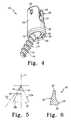
- FIG. 4is the anchor assembly of FIG. 1 assembled and pivoted to position the anchor in the increased angulation cutout of the retainer.
- FIG. 5is a diagram showing angular positions between the receiver member and the anchor member.
- FIG. 6is a section view of a portion the retainer showing a wall profile.
- Anchor assembliesare provided to secure one or more implants along the spinal column that include a retainer in a receiver member.
- the retaineris configured to distribute the forces exerted on the retainer toward the proximal end of the retainer where it may deform without deforming, distorting or altering the retainer where it supports the anchor member in the receiver member. The desired positioning of the anchor member relative to the retainer and receiver member can thus be attained even when the retainer is subject to deformation forces.
- Anchor assembliesare further provided for securing implants along the spinal column that include a retainer positioned about a head of an anchor member in a receiver member.
- the anchor assemblycan include a seat member positioned through a proximal end opening of the retainer in contact with the head of the anchor member.
- Anchor assembliesare also provided for securing implants along the spinal column that include a retainer positioned about a head of an anchor member in a receiver.
- the retainercan include at least one elongated passage extending axially from a distal end thereof to a living hinge portion adjacent a proximal end of the retainer.
- the at least one passagedivides the body of the retainer into wall segments that are moveable relative to one another to accommodate insertion of the anchor member into the retainer and then retain the anchor member therein.
- the wall segmentsare also moveable to accommodate insertion of the retainer into the receiver member, and then return toward a pre-insertion configuration to contact the receiver member and maintain the retainer in the receiver member.
- Anchor assembliesare also provided for securing implants along the spinal column that include a retainer positioned about a head of an anchor member in a receiver member.
- the retainercan include elongated passages extending axially from a distal end thereof and the anchor member can include at least one pin extending from the head thereof that is received in a corresponding one of the at least one passages.
- Anchor assembliesare further provided for securing implants along the spinal column that include a retainer including an elongated frusto-conical configuration positioned about a head of an anchor member in a receiver.
- the retainercan include a distal end with a seat configured to contact the receiver member and support the head of the anchor member in the receiver and a cutout interrupting the seat to provide a location where the anchor member can be received in an angular orientation relative to an axis of the receiver member that is greater than an angular orientation attainable at locations about the seat not occupied by the cutout.
- an anchor assembly 10in an exploded view including an anchor member 12 , a receiver member 20 , a retainer 40 , and a seat member 70 .
- Retainer 40is positionable about a head of anchor member 12 in receiver member 20 .
- An implant 60is positionable on, in or about receiver member 20 , and engaging member 90 is movable relative to implant 60 and engageable in receiver member 20 to secure implant 60 to anchor assembly 10 .
- Anchor assembly 10includes seat member 70 between anchor member 12 and implant 60 .
- Seat member 70includes a proximally oriented implant support surface 74 for contacting implant 60 when engaged in anchor assembly 10 .
- Implant 60can be engaged along one or more vertebrae of the spinal column with one or more anchor assemblies 10 or any other type of fastener in combination with one or more anchor assemblies 10 to provide, for example, a spinal stabilization system.
- Receiver member 20includes a lower portion 22 that can be in the form of a bowl, cylinder or other suitable configuration to form a receptacle to receive retainer 40 with head 18 of anchor member 12 therein.
- Opposite arms 24extend axially and proximally from opposite sides of lower portion 22 .
- Opposing arms 24define an implant receiving passage 21 therebetween that is sized to receive implant 60 proximally of seat member 70 .
- Implant receiving passage 21provides a saddle-type arrangement to receive implant 60 and engaging member 90 .
- Arms 24can each include an internal thread profile to threadingly receive engaging member 90 , although other engagement structures to secure engaging member 90 and receiver member 20 to one another are contemplated.
- Arms 24also each include an outer recess 28 to receive and facilitate engagement by and manipulation with insertion and/or reduction instrumentation (not shown.)
- Anchor member 12 in the illustrated embodimentis a bone screw and includes a shaft 14 having a thread profile 16 therealong and enlarged head 18 at a proximal end of anchor member 12 .
- Head 18includes a proximally opening tool recess (not shown) to receive a driving tool to facilitate engagement of anchor member 12 to the underlying bone.
- a pair of opposite pins 19extend outwardly from the sides of head 18 .
- Pins 19provide an engagement structure to secure and maintain retainer 40 in a desired relative positioning to head 18 .
- Other engagement structuresare also contemplated.
- the sides of head 18can be flat to engage opposite flat surfaces in retainer 40 .
- anchor member 12Various forms for anchor member 12 are contemplated, including threaded and non-threaded anchors, uni-planar and multi-axial pivoting arrangements. Bone engaging portions in the form of hooks, clamps, spikes, cables, interbody implants, fusion devices, non-cannulated screws, fenestrated screws, and bolts, are also contemplated, for example.
- Receiver member 20can be sized to receive seat member 70 adjacent to and proximally of head 18 of anchor member 12 .
- Seat member 70includes a central opening 72 that is in communication with head 18 of anchor member 12 to receive a driving tool (not shown) to apply a driving force to anchor member 12 .
- Seat member 70includes a proximally oriented implant support surface 74 defined about a flange 76 extending about central opening 72 .
- Flange 76can engage receiver member 20 to axially retain seat member 70 therein.
- Flange 76can be integral with seat member 70 , as shown, or can be a separate component.
- Engaging member 90is engageable with receiver member 20 to secure implant 60 in engagement with seat member 70 .
- Engaging member 90can include a proximal break-off portion (not shown) and a receiver engaging portion 94 , although embodiments without a break-off portion are contemplated as shown.
- Receiver engaging portion 94is illustrated as an externally threaded set screw that engages the internal thread profile along arms 24 .
- Other configurationsare also contemplated for engaging member 90 , including internally threaded nuts and multiple component engaging members including internally and/or externally threaded portions.
- Engaging membersare also contemplated that do not threadingly engage receiver member 20 , and engaging relationships that include friction fits, adhesives, fusions, snap fits, and bayonet-locks are contemplated.
- Retainer 40includes a cylindrical body 42 extending between a distal seat end 50 and a proximal end 52 .
- Body 42defines a receptacle 48 for pivotally receiving head 18 of anchor member 12 .
- Body 42can include a generally frusto-conical shape defined by its outer wall surface that tapers proximally.
- the inner shape of body 42can be any shape suitable for pivotally retaining head 18 of anchor member 12 therein.
- Body 42includes a number of axially extending passages 44 extending therealong from distal seat end 50 to a proximal hinge portion 46 .
- Each of the passages 44includes a narrowed distal portion 44 a and a proximal receiving portion 44 b .
- the wall of body 42can reduce in thickness from distal seat end 50 to proximal end 52 .
- the reduced wall thickness adjacent proximal end 52forms living hinge portions 46 in body 42 adjacent the proximal ends of the respective passages 44 .
- the adjacent wall segments formed by the respective passages 44are moveable about hinge portions 46 to expand or contract receptacle 48 in body 42 .
- a lip 56 about distal seat portion 50is configured to normally contact the underside of head 18 of anchor member 12 and retain head 18 in receptacle 48 .
- Head 18 of anchor member 12is inserted into receptacle 48 of retainer 40 through the distal opening defined by distal seat end 50 .
- Pins 19are aligned with respective ones of the passages 44 , and can pass through the aligned ones of the narrowed distal portions 44 a by flexing body 42 outwardly to increase the space between the narrowed distal portions 44 a .
- body 42When pins 19 are received in the proximal slot portions 44 b , body 42 can return toward its pre-flexed condition, and the narrowed distal portions 44 a retain pins 19 in the proximal portions 44 b , coupling anchor member 12 to retainer 40 .
- Lip 56can move outwardly as the respective wall segments including lip 56 are moved outwardly to accommodate insertion of head 18 of anchor member 12 thereby.
- head 18is received into receptacle 48
- return of the wall segments toward their pre-insertion positionengages lip 56 to the distal side of head 18 .
- Body 42can also flex inwardly about these hinge portions 46 to allow the wall segments to radially compress and permit insertion of receiver member 20 over body 42 .
- Pins 19can travel to the proximal ends of passages 44 , moving lip 56 about neck 15 of anchor member 12 and facilitating inward compression and deflection of the wall segments of body 42 about anchor member 12 .
- body 42returns toward its non-compressed state in receiver member 20 .
- Distal seat end 50can abuttingly engage lip 32 about the distal end opening of receiver member 20 , as shown in FIGS. 2 and 3 .
- Head 18 and the pins 19can move axially to the distal ends of proximal portions 44 b of slots 44 , but cannot pass through distal portions 44 a since contact of body 42 with the inner surface of receiver member 20 thereabout prevents outward deflection of the wall segments of body 42 .
- Head 18is thus pivotally captured in retainer 40 with lip 56 of retainer 40 extending about a distally oriented surface of head 18 .
- Distal seat end 50further includes at least one cutout 54 forming a location about seat portion 50 to receive anchor member 12 in an increased angulation position relative to the angulation positions obtainable at the other locations about distal seat end 50 .
- receiver member 20 and anchor member 12include a non-pivoted orientation where both are oriented along axis 11 .
- Anchor member 12 and receiver member 20are pivotal relative to one another so that the axis of anchor member 12 can be position along one of the pivot axes 13 a , 13 b , or along any axis between axes 13 a , 13 b .
- Anchor member 12can also be configured to pivot about axis 11 in a conical pattern so that the relative positioning of the axes of anchor member 12 and receiver member 20 can lie anywhere in the conical space defined by pivot axes 13 a , 13 b .
- Cutout 54is provided to provide a direction of increased angulation and allow greater adjustment capabilities between the axis of the anchor member and the axis of the receiver member. Accordingly, anchor member 12 can be pivoted in the location of cutout 54 to lie on axis 13 c , which forms an angle A 2 with axis 11 that is greater than angle A 1 formed by the axes 13 a , 13 b.
- cutout 54Since hinge portions 46 are located adjacent the proximal end of body 42 and away from cutout 54 , body 42 does not deform adjacent cutout 54 when retainer 40 is inserted into receiver member 20 , or when anchor member 12 is inserted into retainer 40 . Accordingly, the shape of cutout 54 is retained even after retainer insertion to allow anchor member 12 to be precisely and fully received in cutout 54 . As shown in FIG. 5 , cutout 54 receives neck 15 of anchor member 12 between head 18 and shaft 14 in the increased angulation position.
- anchor member 12can be engaged to an underlying bony structure with retainer 40 loosely positioned about head 18 .
- receiver member 20can be assembled prior to engagement of anchor member 12 with bony structure.
- Receiver member 20can be bottom-loaded onto anchor member 12 by positioning receiver member 20 about retainer 40 with retainer member 40 inwardly flexing as the distal end opening of receiver member 20 moves along the outer surface thereof.
- retainer 40returns toward its initial configuration until retainer 40 contacts lip 32 about the distal end opening of receiver member 20 , axially restraining anchor member 12 in receiver member 20 .
- the assembled anchor member and receiver membercan then be engaged to bony structure, unless anchor member was engaged to the bony structure prior to assembly. If employed and if not already so positioned, seat member 70 can then be positioned through the proximal end opening of retainer 40 and into contact with head 18 of anchor member 12 . Receiver member 20 can be manipulated into the desired alignment with implant 60 .
- Anchor member 12 and receiver member 20include a non-pivoted orientation shown in FIGS. 2-3 where each extends along a longitudinal axis 11 . This orientation is shown graphically in FIG. 5 .
- Anchor member 12can be pivotal relative to receiver member 20 to any one of an infinite number of positions defining a cone 13 about axis 11 .
- the angular orientation of anchor member 12 relative to axis 11is greater than at locations about retainer 40 not occupied by cutout 54 .
- retainer 40permits increased angulation of anchor member 12 relative to receiver member 20 to allow greater adjustment capabilities while maintaining sufficient structure about distal seat end 50 of retainer 40 to engage receiver member 20 and maintain anchor member 12 therein.
- Cutout 54can be aligned between arms 24 of receiver member 20 when it is desired to align pivot axis 13 along implant 60 .
- Receiver member 20can be pivoted to its maximum angular orientation relative to anchor member 12 so that anchor member 12 is located within cutout 54 to provide the desired alignment with implant 60 . This can be desirable where the desired approach into the pedicle for anchor member 12 orients axis 11 in the cephalad or caudal direction.
- the increased angulation provided by retainer 40can allow receiver member 20 to be pivoted so that passage 21 can be better aligned with the implant extending along the spinal column. Bending and manipulation of implant 60 to position it in receiver member 20 is minimized.
- implant 60When the desired angular orientation between anchor member 12 and receiver member 20 is obtained, implant 60 is positioned between the arms of receiver member 20 , and secured therein with engaging member 90 .
- Engaging member 90can be advanced into receiver member 20 into contact with implant 60 , thereby pushing implant 60 into contact with seat member 70 and forcing seat member 70 into contact with head 18 of anchor member 12 . In one embodiment, this positions seat member 70 into contact with head 18 of anchor member 12 to rigidly fix anchor member 12 in receiver member 20 .
- anchor member 12maintains a variable angle or semi-rigid arrangement relative to receiver member 20 even when engaging member 90 and seat member 70 are firmly engaged to implant 60 .
- Alternative arrangementsare contemplated where implant 60 is forced into direct contact with anchor member 12 to lock it in position relative to receive member 20 , or where anchor member 12 retains at least limited pivoting capabilities relative to receiver member 20 even when implant 60 is engaged to receiver member 20 .
- Implant 60can be structured either alone or in combination with one or more other implants and/or coupling assemblies to provide a desired stabilization effect.
- implant 60is an elongated spinal rod structured to extend between at least two anchor assemblies 10 , or between at least one anchor assembly 10 and another anchor, to stabilize a motion segment therebetween.
- Various forms for implant 60are contemplated, including rods, tethers, cables, wires, plates, and staples, for example.
- implant 60 and one or more anchor assemblies 10 and other anchors discussed hereinmay be employed unilaterally.
- a second implant 60 and one or more anchor assemblies 10 and other anchorscan be secured to the other side of the vertebral level or levels to be stabilized.
- Multiple implants 60 and corresponding anchor assemblies 10 and other anchorscan be secured along the same side of the spinal column in either uni-lateral or bi-lateral stabilization procedures.
- the underlying boneforms a portion of a vertebral body of the spinal column.
- the underlying bonecan be a part of the anterior, oblique, antero-lateral, lateral or posterior vertebral elements, including the pedicle, spinous process, transverse processes, lamina or facet, for example.
- Applications in techniques along any portion or portions of the spinal columnare contemplated, including the cervical, thoracic, lumbar and sacral regions.
- the anchor assemblies and implantscan be positioned along the spinal column in invasive procedures where skin and tissue are dissected and retracted to expose the implant locations, or in minimally invasive procedures where one or more the anchor assemblies and implants are guided through at least the tissue or access portals adjacent the column to the desired implantation location.
Landscapes
- Health & Medical Sciences (AREA)
- Orthopedic Medicine & Surgery (AREA)
- Life Sciences & Earth Sciences (AREA)
- Surgery (AREA)
- Neurology (AREA)
- Heart & Thoracic Surgery (AREA)
- Engineering & Computer Science (AREA)
- Biomedical Technology (AREA)
- Nuclear Medicine, Radiotherapy & Molecular Imaging (AREA)
- Medical Informatics (AREA)
- Molecular Biology (AREA)
- Animal Behavior & Ethology (AREA)
- General Health & Medical Sciences (AREA)
- Public Health (AREA)
- Veterinary Medicine (AREA)
- Surgical Instruments (AREA)
- Prostheses (AREA)
Abstract
Description
Claims (20)
Priority Applications (7)
| Application Number | Priority Date | Filing Date | Title |
|---|---|---|---|
| US11/254,874US8002806B2 (en) | 2005-10-20 | 2005-10-20 | Bottom loading multi-axial screw assembly |
| PCT/US2006/040615WO2007047711A2 (en) | 2005-10-20 | 2006-10-17 | Bottom loading multi-axial screw assembly |
| AU2006304520AAU2006304520A1 (en) | 2005-10-20 | 2006-10-17 | Bottom loading multi-axial screw assembly |
| JP2008536745AJP5078900B2 (en) | 2005-10-20 | 2006-10-17 | System for stabilizing bone parts |
| EP06817080AEP1951133A2 (en) | 2005-10-20 | 2006-10-17 | Bottom loading multi-axial screw assembly |
| KR1020087012007AKR101421242B1 (en) | 2005-10-20 | 2006-10-17 | Bottom loading multi-axial screw assembly |
| CA002625422ACA2625422A1 (en) | 2005-10-20 | 2006-10-17 | Bottom loading multi-axial screw assembly |
Applications Claiming Priority (1)
| Application Number | Priority Date | Filing Date | Title |
|---|---|---|---|
| US11/254,874US8002806B2 (en) | 2005-10-20 | 2005-10-20 | Bottom loading multi-axial screw assembly |
Publications (2)
| Publication Number | Publication Date |
|---|---|
| US20070090238A1 US20070090238A1 (en) | 2007-04-26 |
| US8002806B2true US8002806B2 (en) | 2011-08-23 |
Family
ID=37719647
Family Applications (1)
| Application Number | Title | Priority Date | Filing Date |
|---|---|---|---|
| US11/254,874Active2029-10-24US8002806B2 (en) | 2005-10-20 | 2005-10-20 | Bottom loading multi-axial screw assembly |
Country Status (7)
| Country | Link |
|---|---|
| US (1) | US8002806B2 (en) |
| EP (1) | EP1951133A2 (en) |
| JP (1) | JP5078900B2 (en) |
| KR (1) | KR101421242B1 (en) |
| AU (1) | AU2006304520A1 (en) |
| CA (1) | CA2625422A1 (en) |
| WO (1) | WO2007047711A2 (en) |
Cited By (51)
| Publication number | Priority date | Publication date | Assignee | Title |
|---|---|---|---|---|
| US20100145394A1 (en)* | 2008-11-03 | 2010-06-10 | Harvey Dustin M | Uni-planer bone fixation assembly |
| US20100179603A1 (en)* | 2004-10-25 | 2010-07-15 | X-Spine Systems, Inc. | Pedicle screw systems and methods of assembling/installing the same |
| US20100191293A1 (en)* | 2003-06-18 | 2010-07-29 | Jackson Roger P | Polyaxial bone anchor with spline capture connection and lower pressure insert |
| US20100204735A1 (en)* | 2009-02-11 | 2010-08-12 | Gephart Matthew P | Wide Angulation Coupling Members For Bone Fixation System |
| US20100305621A1 (en)* | 2009-06-02 | 2010-12-02 | Alphatec Spine, Inc. | Bone screw assembly for limited angulation |
| US20110106174A1 (en)* | 2009-10-30 | 2011-05-05 | Warsaw Orthopedic, Inc. | Direct Control Spinal Implant |
| US20110213419A1 (en)* | 2007-10-23 | 2011-09-01 | Blackstone Medical Inc. | Spinal Implant |
| US20120089194A1 (en)* | 2005-11-21 | 2012-04-12 | Strausbaugh William L | Polyaxial bone anchors with increased angulation |
| US20120172932A1 (en)* | 2010-12-10 | 2012-07-05 | Lutz Biedermann | Bone anchoring device |
| US20120179211A1 (en)* | 2010-12-10 | 2012-07-12 | Lutz Biedermann | Receiving part for receiving a rod for coupling the rod to a bone anchoring element and bone anchoring device with such a receiving part |
| US20120277805A1 (en)* | 2011-04-29 | 2012-11-01 | Warsaw Orthopedic, Inc. | Rotatable Base Multi-Axial Screw Assembly |
| US8348952B2 (en) | 2006-01-26 | 2013-01-08 | Depuy International Ltd. | System and method for cooling a spinal correction device comprising a shape memory material for corrective spinal surgery |
| US8382806B2 (en) | 2005-07-29 | 2013-02-26 | X-Spine Systems, Inc. | Capless multiaxial screw and spinal fixation assembly and method |
| US8414614B2 (en) | 2005-10-22 | 2013-04-09 | Depuy International Ltd | Implant kit for supporting a spinal column |
| US8425563B2 (en) | 2006-01-13 | 2013-04-23 | Depuy International Ltd. | Spinal rod support kit |
| US8430914B2 (en) | 2007-10-24 | 2013-04-30 | Depuy Spine, Inc. | Assembly for orthopaedic surgery |
| US8444681B2 (en) | 2009-06-15 | 2013-05-21 | Roger P. Jackson | Polyaxial bone anchor with pop-on shank, friction fit retainer and winged insert |
| US20130338721A1 (en)* | 2012-05-29 | 2013-12-19 | Biedermann Technologies Gmbh & Co. Kg | Receiving part for receiving a rod for coupling the rod to a bone anchoring element and a bone anchoring device with such a receiving part |
| US20140018866A1 (en)* | 2012-01-01 | 2014-01-16 | Vaskrsije Jankovic | Surgical screw assembly with increased articulation |
| US20140172023A1 (en)* | 2006-04-12 | 2014-06-19 | Alphatec Spine, Inc. | Pedicle screw assembly |
| US8808307B2 (en) | 2010-10-13 | 2014-08-19 | Pioneer Surgical Technology, Inc. | Driver for a surgical device |
| US8911479B2 (en) | 2012-01-10 | 2014-12-16 | Roger P. Jackson | Multi-start closures for open implants |
| US9005205B2 (en) | 2013-03-04 | 2015-04-14 | Degen Medical, Inc. | Rod insertion tools, rods and methods |
| US9060813B1 (en) | 2008-02-29 | 2015-06-23 | Nuvasive, Inc. | Surgical fixation system and related methods |
| US9084634B1 (en)* | 2010-07-09 | 2015-07-21 | Theken Spine, Llc | Uniplanar screw |
| US9101426B2 (en) | 2012-10-11 | 2015-08-11 | Stryker Trauma Sa | Cable plug |
| US9168069B2 (en) | 2009-06-15 | 2015-10-27 | Roger P. Jackson | Polyaxial bone anchor with pop-on shank and winged insert with lower skirt for engaging a friction fit retainer |
| US20160160906A1 (en)* | 2014-12-05 | 2016-06-09 | Black & Decker Inc. | Swivel hanger |
| US9387013B1 (en) | 2011-03-01 | 2016-07-12 | Nuvasive, Inc. | Posterior cervical fixation system |
| US9393047B2 (en) | 2009-06-15 | 2016-07-19 | Roger P. Jackson | Polyaxial bone anchor with pop-on shank and friction fit retainer with low profile edge lock |
| US9421041B2 (en) | 2008-09-09 | 2016-08-23 | Marc E. Richelsoph | Polyaxial screw assembly |
| US9453526B2 (en) | 2013-04-30 | 2016-09-27 | Degen Medical, Inc. | Bottom-loading anchor assembly |
| US9451992B2 (en)* | 2010-12-01 | 2016-09-27 | Facet-Link Inc. | Variable angle bone screw fixation arrangement |
| US9480517B2 (en) | 2009-06-15 | 2016-11-01 | Roger P. Jackson | Polyaxial bone anchor with pop-on shank, shank, friction fit retainer, winged insert and low profile edge lock |
| US20160341245A1 (en)* | 2014-12-05 | 2016-11-24 | Black & Decker Inc. | Swivel hanger system |
| US9526531B2 (en) | 2013-10-07 | 2016-12-27 | Intelligent Implant Systems, Llc | Polyaxial plate rod system and surgical procedure |
| US9655659B2 (en) | 2013-04-20 | 2017-05-23 | Degen Medical, Inc. | Anchor tower |
| US20170181862A1 (en)* | 2005-02-22 | 2017-06-29 | Globus Medical, Inc. | Polyaxial orthopedic fastening apparatus with independent locking modes |
| USD799949S1 (en) | 2007-10-24 | 2017-10-17 | Nuvasive, Inc. | Favored angle screw |
| US9974571B2 (en) | 2008-09-12 | 2018-05-22 | DePuy Synthes Products, Inc. | Spinal stabilizing and guiding fixation system |
| US9980753B2 (en) | 2009-06-15 | 2018-05-29 | Roger P Jackson | pivotal anchor with snap-in-place insert having rotation blocking extensions |
| US10034691B1 (en) | 2015-12-03 | 2018-07-31 | Nuvasive, Inc. | Bone anchor |
| US10105163B2 (en) | 2009-04-15 | 2018-10-23 | DePuy Synthes Products, Inc. | Revision connector for spinal constructs |
| US10136923B2 (en) | 2007-07-20 | 2018-11-27 | DePuy Synthes Products, Inc. | Polyaxial bone fixation element |
| US10154859B2 (en) | 2008-09-29 | 2018-12-18 | DePuy Synthes Products, Inc. | Polyaxial bottom-loading screw and rod assembly |
| US10194951B2 (en) | 2005-05-10 | 2019-02-05 | Roger P. Jackson | Polyaxial bone anchor with compound articulation and pop-on shank |
| US10499968B2 (en) | 2014-08-08 | 2019-12-10 | Stryker European Holdings I, Llc | Cable plugs for bone plates |
| US10507043B1 (en) | 2017-10-11 | 2019-12-17 | Seaspine Orthopedics Corporation | Collet for a polyaxial screw assembly |
| US10603083B1 (en) | 2010-07-09 | 2020-03-31 | Theken Spine, Llc | Apparatus and method for limiting a range of angular positions of a screw |
| US11006978B2 (en) | 2009-06-17 | 2021-05-18 | DePuy Synthes Products, Inc. | Revision connector for spinal constructs |
| US11751918B2 (en)* | 2020-03-12 | 2023-09-12 | Biedermann Technologies Gmbh & Co. Kg | Coupling device for use with a bone anchoring element and bone anchoring device with such a coupling device |
Families Citing this family (94)
| Publication number | Priority date | Publication date | Assignee | Title |
|---|---|---|---|---|
| US7833250B2 (en) | 2004-11-10 | 2010-11-16 | Jackson Roger P | Polyaxial bone screw with helically wound capture connection |
| US8876868B2 (en) | 2002-09-06 | 2014-11-04 | Roger P. Jackson | Helical guide and advancement flange with radially loaded lip |
| US6716214B1 (en)* | 2003-06-18 | 2004-04-06 | Roger P. Jackson | Polyaxial bone screw with spline capture connection |
| US7377923B2 (en) | 2003-05-22 | 2008-05-27 | Alphatec Spine, Inc. | Variable angle spinal screw assembly |
| US7766915B2 (en) | 2004-02-27 | 2010-08-03 | Jackson Roger P | Dynamic fixation assemblies with inner core and outer coil-like member |
| US8366753B2 (en) | 2003-06-18 | 2013-02-05 | Jackson Roger P | Polyaxial bone screw assembly with fixed retaining structure |
| US8926670B2 (en) | 2003-06-18 | 2015-01-06 | Roger P. Jackson | Polyaxial bone screw assembly |
| US7776067B2 (en) | 2005-05-27 | 2010-08-17 | Jackson Roger P | Polyaxial bone screw with shank articulation pressure insert and method |
| US7967850B2 (en) | 2003-06-18 | 2011-06-28 | Jackson Roger P | Polyaxial bone anchor with helical capture connection, insert and dual locking assembly |
| US8226690B2 (en) | 2005-07-22 | 2012-07-24 | The Board Of Trustees Of The Leland Stanford Junior University | Systems and methods for stabilization of bone structures |
| US8267969B2 (en) | 2004-10-20 | 2012-09-18 | Exactech, Inc. | Screw systems and methods for use in stabilization of bone structures |
| US7604655B2 (en) | 2004-10-25 | 2009-10-20 | X-Spine Systems, Inc. | Bone fixation system and method for using the same |
| US8926672B2 (en) | 2004-11-10 | 2015-01-06 | Roger P. Jackson | Splay control closure for open bone anchor |
| WO2006058221A2 (en) | 2004-11-24 | 2006-06-01 | Abdou Samy M | Devices and methods for inter-vertebral orthopedic device placement |
| US7901437B2 (en) | 2007-01-26 | 2011-03-08 | Jackson Roger P | Dynamic stabilization member with molded connection |
| US8523865B2 (en) | 2005-07-22 | 2013-09-03 | Exactech, Inc. | Tissue splitter |
| US7955358B2 (en) | 2005-09-19 | 2011-06-07 | Albert Todd J | Bone screw apparatus, system and method |
| WO2007041702A2 (en) | 2005-10-04 | 2007-04-12 | Alphaspine, Inc. | Pedicle screw system with provisional locking aspects |
| US8075599B2 (en) | 2005-10-18 | 2011-12-13 | Warsaw Orthopedic, Inc. | Adjustable bone anchor assembly |
| GB0521585D0 (en)* | 2005-10-22 | 2005-11-30 | Depuy Int Ltd | A spinal support rod |
| US8097025B2 (en) | 2005-10-25 | 2012-01-17 | X-Spine Systems, Inc. | Pedicle screw system configured to receive a straight or curved rod |
| US20070270815A1 (en)* | 2006-04-20 | 2007-11-22 | Chris Johnson | Bone anchors with end-loading receivers for elongated connecting elements in spinal surgical procedures |
| US8096996B2 (en) | 2007-03-20 | 2012-01-17 | Exactech, Inc. | Rod reducer |
| ES2334811T3 (en)* | 2006-11-17 | 2010-03-16 | Biedermann Motech Gmbh | OSEO ANCHORAGE DEVICE. |
| US8133261B2 (en) | 2007-02-26 | 2012-03-13 | Depuy Spine, Inc. | Intra-facet fixation device and method of use |
| US8197513B2 (en) | 2007-04-13 | 2012-06-12 | Depuy Spine, Inc. | Facet fixation and fusion wedge and method of use |
| US8043334B2 (en) | 2007-04-13 | 2011-10-25 | Depuy Spine, Inc. | Articulating facet fusion screw |
| US8894685B2 (en) | 2007-04-13 | 2014-11-25 | DePuy Synthes Products, LLC | Facet fixation and fusion screw and washer assembly and method of use |
| PL2170192T3 (en)* | 2007-07-20 | 2011-07-29 | Synthes Gmbh | Polyaxial bone fixation element |
| ES2348814T3 (en) | 2007-07-31 | 2010-12-15 | Biedermann Motech Gmbh | ANCHORAGE DEVICE Ã “SEO. |
| FR2920959B1 (en) | 2007-09-17 | 2010-09-10 | Clariance | VERTEBRAL ANCHORING DEVICE. |
| US8267361B1 (en)* | 2007-10-18 | 2012-09-18 | Acratech, Inc. | Attachment to a long lens support device which functions as both a ball head and a gimble head |
| US8038701B2 (en)* | 2007-10-22 | 2011-10-18 | K2M, Inc. | Uni-planar, taper lock bone screw |
| EP2249721B1 (en)* | 2008-02-12 | 2017-07-05 | Texas Scottish Rite Hospital For Children | Fast adjust external fixation connection rod |
| AU2010260521C1 (en)* | 2008-08-01 | 2013-08-01 | Roger P. Jackson | Longitudinal connecting member with sleeved tensioned cords |
| EP2355725B1 (en) | 2008-09-05 | 2017-03-08 | Synthes GmbH | Bone fixation assembly |
| US8506601B2 (en)* | 2008-10-14 | 2013-08-13 | Pioneer Surgical Technology, Inc. | Low profile dual locking fixation system and offset anchor member |
| US8998959B2 (en)* | 2009-06-15 | 2015-04-07 | Roger P Jackson | Polyaxial bone anchors with pop-on shank, fully constrained friction fit retainer and lock and release insert |
| US9668771B2 (en) | 2009-06-15 | 2017-06-06 | Roger P Jackson | Soft stabilization assemblies with off-set connector |
| US11229457B2 (en) | 2009-06-15 | 2022-01-25 | Roger P. Jackson | Pivotal bone anchor assembly with insert tool deployment |
| US11464549B2 (en) | 2009-06-15 | 2022-10-11 | Roger P. Jackson | Pivotal bone anchor assembly with horizontal tool engagement grooves and insert with upright arms having flared outer portions |
| EP2485654B1 (en) | 2009-10-05 | 2021-05-05 | Jackson P. Roger | Polyaxial bone anchor with non-pivotable retainer and pop-on shank, some with friction fit |
| US9044272B2 (en) | 2009-11-09 | 2015-06-02 | Ebi, Llc | Multiplanar bone anchor system |
| US8449578B2 (en) | 2009-11-09 | 2013-05-28 | Ebi, Llc | Multiplanar bone anchor system |
| WO2011057227A1 (en) | 2009-11-09 | 2011-05-12 | Applied Orthopaedics Llp | Apparatus for retaining bone |
| DE112010004338B4 (en) | 2009-11-10 | 2019-06-27 | Nuvasive, Inc. | DEVICE FOR IMPLEMENTING SPINE SURGERY |
| US8764806B2 (en) | 2009-12-07 | 2014-07-01 | Samy Abdou | Devices and methods for minimally invasive spinal stabilization and instrumentation |
| US8636655B1 (en) | 2010-01-19 | 2014-01-28 | Ronald Childs | Tissue retraction system and related methods |
| KR100980459B1 (en)* | 2010-03-30 | 2010-09-07 | 주식회사 지에스메디칼 | Cervical screw |
| US9089372B2 (en) | 2010-07-12 | 2015-07-28 | DePuy Synthes Products, Inc. | Pedicular facet fusion screw with plate |
| AU2011324058A1 (en) | 2010-11-02 | 2013-06-20 | Roger P. Jackson | Polyaxial bone anchor with pop-on shank and pivotable retainer |
| US9044274B2 (en) | 2010-12-01 | 2015-06-02 | Amendia, Inc. | Bone screw system |
| US9307972B2 (en) | 2011-05-10 | 2016-04-12 | Nuvasive, Inc. | Method and apparatus for performing spinal fusion surgery |
| US9060818B2 (en) | 2011-09-01 | 2015-06-23 | DePuy Synthes Products, Inc. | Bone implants |
| US8845728B1 (en) | 2011-09-23 | 2014-09-30 | Samy Abdou | Spinal fixation devices and methods of use |
| US8469325B2 (en)* | 2011-10-26 | 2013-06-25 | Tsung-Yao Yu | Musical instrument stand with an angle adjustment function |
| US20130226240A1 (en) | 2012-02-22 | 2013-08-29 | Samy Abdou | Spinous process fixation devices and methods of use |
| US9198767B2 (en) | 2012-08-28 | 2015-12-01 | Samy Abdou | Devices and methods for spinal stabilization and instrumentation |
| US9320617B2 (en) | 2012-10-22 | 2016-04-26 | Cogent Spine, LLC | Devices and methods for spinal stabilization and instrumentation |
| KR200466455Y1 (en) | 2012-11-12 | 2013-04-16 | 차종학 | vertebra implant |
| US8911478B2 (en) | 2012-11-21 | 2014-12-16 | Roger P. Jackson | Splay control closure for open bone anchor |
| US10058354B2 (en) | 2013-01-28 | 2018-08-28 | Roger P. Jackson | Pivotal bone anchor assembly with frictional shank head seating surfaces |
| US8852239B2 (en) | 2013-02-15 | 2014-10-07 | Roger P Jackson | Sagittal angle screw with integral shank and receiver |
| US9517091B2 (en)* | 2013-03-15 | 2016-12-13 | Warsaw Orthopediac, Inc. | Locking mechanism |
| CN105378366B (en)* | 2013-06-07 | 2017-03-29 | 乔鲍·卡莱 | Head assembly for supporting and adjusting the position of optical or electronic devices |
| US9566092B2 (en) | 2013-10-29 | 2017-02-14 | Roger P. Jackson | Cervical bone anchor with collet retainer and outer locking sleeve |
| US9717533B2 (en) | 2013-12-12 | 2017-08-01 | Roger P. Jackson | Bone anchor closure pivot-splay control flange form guide and advancement structure |
| US9451993B2 (en) | 2014-01-09 | 2016-09-27 | Roger P. Jackson | Bi-radial pop-on cervical bone anchor |
| JP5564629B1 (en)* | 2014-02-20 | 2014-07-30 | 平和精機工業株式会社 | Tripod device |
| US10918419B2 (en)* | 2014-04-01 | 2021-02-16 | K2M, Inc. | Spinal fixation device |
| US9549765B2 (en) | 2014-04-03 | 2017-01-24 | Zimmer Spine, Inc. | Uniplanar bone screw |
| US10064658B2 (en) | 2014-06-04 | 2018-09-04 | Roger P. Jackson | Polyaxial bone anchor with insert guides |
| US9597119B2 (en) | 2014-06-04 | 2017-03-21 | Roger P. Jackson | Polyaxial bone anchor with polymer sleeve |
| US9795370B2 (en) | 2014-08-13 | 2017-10-24 | Nuvasive, Inc. | Minimally disruptive retractor and associated methods for spinal surgery |
| US10543021B2 (en) | 2014-10-21 | 2020-01-28 | Roger P. Jackson | Pivotal bone anchor assembly having an open ring positioner for a retainer |
| US9924975B2 (en) | 2014-10-21 | 2018-03-27 | Roger P. Jackson | Bone anchor having a snap-fit assembly |
| CN104799931B (en)* | 2015-04-13 | 2017-07-07 | 李贵涛 | Nest mortar rail chain type replacement and fixation dynamic pedicle screw system |
| US10130395B2 (en)* | 2015-08-17 | 2018-11-20 | Globus Medical, Inc. | Modular uniplanar pedicle screw assembly for use with a polyaxial bone fastener |
| US10857003B1 (en) | 2015-10-14 | 2020-12-08 | Samy Abdou | Devices and methods for vertebral stabilization |
| US9757165B2 (en) | 2015-10-23 | 2017-09-12 | Warsaw Orthopedic, Inc. | Spinal implant system and method |
| US10744000B1 (en) | 2016-10-25 | 2020-08-18 | Samy Abdou | Devices and methods for vertebral bone realignment |
| US10973648B1 (en) | 2016-10-25 | 2021-04-13 | Samy Abdou | Devices and methods for vertebral bone realignment |
| US10368916B2 (en)* | 2017-01-11 | 2019-08-06 | Warsaw Orthopedic, Inc. | Spinal implant system and methods of use |
| US11179248B2 (en) | 2018-10-02 | 2021-11-23 | Samy Abdou | Devices and methods for spinal implantation |
| DE102018126958A1 (en)* | 2018-10-29 | 2020-04-30 | Böllhoff Verbindungstechnik GmbH | Connection unit for connecting two components with a space between them |
| US11219469B2 (en)* | 2018-12-03 | 2022-01-11 | Warsaw Orthopedic, Inc. | Bone screw and method of manufacture |
| GB2580440A (en) | 2019-01-07 | 2020-07-22 | Portable Multimedia Ltd | Housing and device |
| US11426223B2 (en)* | 2019-02-22 | 2022-08-30 | Warsaw Orthopedic, Inc. | Bone screw and method of manufacture |
| WO2021263088A1 (en) | 2020-06-26 | 2021-12-30 | K2M, Inc. | Modular head assembly |
| WO2022108875A1 (en)* | 2020-11-19 | 2022-05-27 | K2M, Inc. | Modular head assembly for spinal fixation |
| US11439437B1 (en)* | 2021-06-09 | 2022-09-13 | Medos International Sarl | Bottom loading bone anchor assemblies with drag retaining ring and related methods |
| EP4580530A1 (en)* | 2022-09-01 | 2025-07-09 | Getset Surgical SA | Bone securing systems |
| EP4437983A1 (en)* | 2023-03-30 | 2024-10-02 | Biedermann Technologies GmbH & Co. KG | Coupling device for coupling a rod to a bone anchor and system of such a coupling device and at least two bone anchors |
| EP4570198A1 (en)* | 2023-12-15 | 2025-06-18 | Biedermann Technologies GmbH & Co. KG | Coupling device for coupling a rod to a bone anchor and system of such a coupling device and at least two bone anchors |
Citations (54)
| Publication number | Priority date | Publication date | Assignee | Title |
|---|---|---|---|---|
| US4946458A (en) | 1986-04-25 | 1990-08-07 | Harms Juergen | Pedicle screw |
| DE4107480A1 (en) | 1991-03-08 | 1992-09-10 | Heinrich Ulrich | Screw for fixing appliance for correcting spinal column - has specially shaped head to receive appliance rod |
| US5190543A (en) | 1990-11-26 | 1993-03-02 | Synthes (U.S.A.) | Anchoring device |
| DE4243951A1 (en) | 1992-12-23 | 1994-07-07 | Plus Endoprothetik Ag Rotkreuz | Device for stiffening a spine and tools for its assembly and / or disassembly |
| US5501684A (en) | 1992-06-25 | 1996-03-26 | Synthes (U.S.A.) | Osteosynthetic fixation device |
| US5520689A (en) | 1992-06-04 | 1996-05-28 | Synthes (U.S.A.) | Osteosynthetic fastening device |
| US5549608A (en) | 1995-07-13 | 1996-08-27 | Fastenetix, L.L.C. | Advanced polyaxial locking screw and coupling element device for use with rod fixation apparatus |
| US5562661A (en) | 1995-03-16 | 1996-10-08 | Alphatec Manufacturing Incorporated | Top tightening bone fixation apparatus |
| US5575792A (en) | 1995-07-14 | 1996-11-19 | Fastenetix, L.L.C. | Extending hook and polyaxial coupling element device for use with top loading rod fixation devices |
| US5586984A (en) | 1995-07-13 | 1996-12-24 | Fastenetix, L.L.C. | Polyaxial locking screw and coupling element assembly for use with rod fixation apparatus |
| US5647873A (en) | 1995-04-13 | 1997-07-15 | Fastenetix, L.L.C. | Bicentric polyaxial locking screw and coupling element |
| DE19605640A1 (en) | 1996-02-15 | 1997-08-21 | Plus Endoprothetik Ag | Osteosynthetic fastener |
| US5672176A (en) | 1995-03-15 | 1997-09-30 | Biedermann; Lutz | Anchoring member |
| US5690630A (en) | 1995-04-13 | 1997-11-25 | Fastenetix, Llc | Polyaxial pedicle screw |
| US5728098A (en) | 1996-11-07 | 1998-03-17 | Sdgi Holdings, Inc. | Multi-angle bone screw assembly using shape-memory technology |
| US5733285A (en) | 1995-07-13 | 1998-03-31 | Fastenetix, Llc | Polyaxial locking mechanism |
| WO1998025534A1 (en) | 1996-12-12 | 1998-06-18 | Synthes Ag Chur | Device for connecting a longitudinal support to a pedicle screw |
| US5797911A (en) | 1996-09-24 | 1998-08-25 | Sdgi Holdings, Inc. | Multi-axial bone screw assembly |
| US5882350A (en) | 1995-04-13 | 1999-03-16 | Fastenetix, Llc | Polyaxial pedicle screw having a threaded and tapered compression locking mechanism |
| US5885286A (en) | 1996-09-24 | 1999-03-23 | Sdgi Holdings, Inc. | Multi-axial bone screw assembly |
| US5891145A (en) | 1997-07-14 | 1999-04-06 | Sdgi Holdings, Inc. | Multi-axial screw |
| US5989254A (en)* | 1997-05-20 | 1999-11-23 | Katz; Akiva Raphael | Pedicle screw assembly |
| US6074391A (en) | 1997-06-16 | 2000-06-13 | Howmedica Gmbh | Receiving part for a retaining component of a vertebral column implant |
| US6132432A (en) | 1996-10-18 | 2000-10-17 | Spinal Innovations Llc | Spinal implant fixation assembly |
| US6187005B1 (en)* | 1998-09-11 | 2001-02-13 | Synthes (Usa) | Variable angle spinal fixation system |
| US6248105B1 (en)* | 1997-05-17 | 2001-06-19 | Synthes (U.S.A.) | Device for connecting a longitudinal support with a pedicle screw |
| US6280442B1 (en) | 1999-09-01 | 2001-08-28 | Sdgi Holdings, Inc. | Multi-axial bone screw assembly |
| US6331179B1 (en)* | 2000-01-06 | 2001-12-18 | Spinal Concepts, Inc. | System and method for stabilizing the human spine with a bone plate |
| US6368321B1 (en) | 2000-12-04 | 2002-04-09 | Roger P. Jackson | Lockable swivel head bone screw |
| US6402752B2 (en) | 2000-02-07 | 2002-06-11 | Ulrich Gmbh & Co. Kg | Polyaxial pedicle-screw |
| US6520963B1 (en) | 2001-08-13 | 2003-02-18 | Mckinley Lawrence M. | Vertebral alignment and fixation assembly |
| US6537276B2 (en) | 1992-03-02 | 2003-03-25 | Stryker Trauma Gmbh | Apparatus for bracing vertebrae |
| US6692500B2 (en) | 2001-10-15 | 2004-02-17 | Gary Jack Reed | Orthopedic stabilization device and method |
| US20040039384A1 (en)* | 2002-08-21 | 2004-02-26 | Boehm Frank H. | Device and method for pertcutaneous placement of lumbar pedicle screws and connecting rods |
| US6716214B1 (en)* | 2003-06-18 | 2004-04-06 | Roger P. Jackson | Polyaxial bone screw with spline capture connection |
| US6736820B2 (en) | 2000-11-10 | 2004-05-18 | Biedermann Motech Gmbh | Bone screw |
| US20040097933A1 (en) | 2002-11-19 | 2004-05-20 | Rodolphe Lourdel | Vertebral anchoring device and its blocking device on a polyaxial screw |
| US20040172022A1 (en) | 2002-10-30 | 2004-09-02 | Landry Michael E. | Bone fastener assembly for a spinal stabilization system |
| US6800078B2 (en) | 2001-11-07 | 2004-10-05 | Lock-N-Stitch, Inc. | Orthopedic stabilization device and method |
| US20040236330A1 (en) | 2003-05-22 | 2004-11-25 | Thomas Purcell | Variable angle spinal screw assembly |
| US6837889B2 (en) | 2002-03-01 | 2005-01-04 | Endius Incorporated | Apparatus for connecting a longitudinal member to a bone portion |
| WO2005018471A1 (en) | 2003-08-20 | 2005-03-03 | Sdgi Holdings, Inc. | Multi-axial orthopedic device and system, e.g. for spinal surgery |
| US20050154391A1 (en)* | 2003-12-30 | 2005-07-14 | Thomas Doherty | Bone anchor assemblies |
| US20050159750A1 (en) | 2003-12-30 | 2005-07-21 | Thomas Doherty | Bone anchor assemblies and methods of manufacturing bone anchor assemblies |
| US20050177154A1 (en) | 2000-09-22 | 2005-08-11 | Missoum Moumene | Locking cap assembly for spinal fixation instrumentation |
| US20050187548A1 (en) | 2004-01-13 | 2005-08-25 | Butler Michael S. | Pedicle screw constructs for spine fixation systems |
| US20050261687A1 (en) | 2004-04-20 | 2005-11-24 | Laszlo Garamszegi | Pedicle screw assembly |
| US20060089644A1 (en)* | 2004-10-27 | 2006-04-27 | Felix Brent A | Spinal stabilizing system |
| US20070043355A1 (en) | 2003-05-28 | 2007-02-22 | Stephane Bette | Connecting device for spinal osteosynthesis |
| US20070088357A1 (en) | 2005-10-18 | 2007-04-19 | Sdgi Holdings, Inc. | Adjustable bone anchor assembly |
| US20080195159A1 (en) | 2005-02-08 | 2008-08-14 | Henning Kloss | Spine Fixator |
| US20080306546A1 (en) | 2007-06-05 | 2008-12-11 | Spartek Medical, Inc. | Bone anchor with a yoke-shaped anchor head for a dynamic stabilization and motion preservation spinal implantation system and method |
| US7559943B2 (en) | 2004-06-09 | 2009-07-14 | Zimmer Spine, Inc. | Spinal fixation device with internal drive structure |
| WO2009106733A2 (en) | 2007-12-21 | 2009-09-03 | Timoteo Michel | Pivoting connection device for spinal osteosynthesis screw |
Family Cites Families (1)
| Publication number | Priority date | Publication date | Assignee | Title |
|---|---|---|---|---|
| DE10246177A1 (en)* | 2002-10-02 | 2004-04-22 | Biedermann Motech Gmbh | Anchor element consists of screw with head, bone-thread section on shank and holder joining rod-shaped part to screw. with cavities in wall, and thread-free end of shank |
- 2005
- 2005-10-20USUS11/254,874patent/US8002806B2/enactiveActive
- 2006
- 2006-10-17CACA002625422Apatent/CA2625422A1/ennot_activeAbandoned
- 2006-10-17WOPCT/US2006/040615patent/WO2007047711A2/enactiveApplication Filing
- 2006-10-17KRKR1020087012007Apatent/KR101421242B1/ennot_activeExpired - Fee Related
- 2006-10-17AUAU2006304520Apatent/AU2006304520A1/ennot_activeAbandoned
- 2006-10-17JPJP2008536745Apatent/JP5078900B2/ennot_activeExpired - Fee Related
- 2006-10-17EPEP06817080Apatent/EP1951133A2/ennot_activeWithdrawn
Patent Citations (63)
| Publication number | Priority date | Publication date | Assignee | Title |
|---|---|---|---|---|
| US4946458A (en) | 1986-04-25 | 1990-08-07 | Harms Juergen | Pedicle screw |
| US5190543A (en) | 1990-11-26 | 1993-03-02 | Synthes (U.S.A.) | Anchoring device |
| DE4107480A1 (en) | 1991-03-08 | 1992-09-10 | Heinrich Ulrich | Screw for fixing appliance for correcting spinal column - has specially shaped head to receive appliance rod |
| US6537276B2 (en) | 1992-03-02 | 2003-03-25 | Stryker Trauma Gmbh | Apparatus for bracing vertebrae |
| US5520689A (en) | 1992-06-04 | 1996-05-28 | Synthes (U.S.A.) | Osteosynthetic fastening device |
| US5501684A (en) | 1992-06-25 | 1996-03-26 | Synthes (U.S.A.) | Osteosynthetic fixation device |
| DE4243951A1 (en) | 1992-12-23 | 1994-07-07 | Plus Endoprothetik Ag Rotkreuz | Device for stiffening a spine and tools for its assembly and / or disassembly |
| EP0626828A1 (en) | 1992-12-23 | 1994-12-07 | Plus Endoprothetik Ag | System for osteosynthesis along the spinal column, connecting element for such a system and tool for assembling and/or dismantling the same. |
| US5536268A (en) | 1992-12-23 | 1996-07-16 | Plus Endoprothetik Ag | System for osteosynthesis at the vertebral column, connecting element for such a system and tool for its placement and removal |
| US5672176A (en) | 1995-03-15 | 1997-09-30 | Biedermann; Lutz | Anchoring member |
| US5562661A (en) | 1995-03-16 | 1996-10-08 | Alphatec Manufacturing Incorporated | Top tightening bone fixation apparatus |
| US5817094A (en) | 1995-04-13 | 1998-10-06 | Fastenetix, Llc | Polyaxial locking screw and coupling element |
| US5882350A (en) | 1995-04-13 | 1999-03-16 | Fastenetix, Llc | Polyaxial pedicle screw having a threaded and tapered compression locking mechanism |
| US5690630A (en) | 1995-04-13 | 1997-11-25 | Fastenetix, Llc | Polyaxial pedicle screw |
| US5647873A (en) | 1995-04-13 | 1997-07-15 | Fastenetix, L.L.C. | Bicentric polyaxial locking screw and coupling element |
| US5586984A (en) | 1995-07-13 | 1996-12-24 | Fastenetix, L.L.C. | Polyaxial locking screw and coupling element assembly for use with rod fixation apparatus |
| US5733285A (en) | 1995-07-13 | 1998-03-31 | Fastenetix, Llc | Polyaxial locking mechanism |
| US5549608A (en) | 1995-07-13 | 1996-08-27 | Fastenetix, L.L.C. | Advanced polyaxial locking screw and coupling element device for use with rod fixation apparatus |
| US5575792A (en) | 1995-07-14 | 1996-11-19 | Fastenetix, L.L.C. | Extending hook and polyaxial coupling element device for use with top loading rod fixation devices |
| DE19605640A1 (en) | 1996-02-15 | 1997-08-21 | Plus Endoprothetik Ag | Osteosynthetic fastener |
| US5797911A (en) | 1996-09-24 | 1998-08-25 | Sdgi Holdings, Inc. | Multi-axial bone screw assembly |
| US5885286A (en) | 1996-09-24 | 1999-03-23 | Sdgi Holdings, Inc. | Multi-axial bone screw assembly |
| US6132432A (en) | 1996-10-18 | 2000-10-17 | Spinal Innovations Llc | Spinal implant fixation assembly |
| US5728098A (en) | 1996-11-07 | 1998-03-17 | Sdgi Holdings, Inc. | Multi-angle bone screw assembly using shape-memory technology |
| US6063090A (en)* | 1996-12-12 | 2000-05-16 | Synthes (U.S.A.) | Device for connecting a longitudinal support to a pedicle screw |
| WO1998025534A1 (en) | 1996-12-12 | 1998-06-18 | Synthes Ag Chur | Device for connecting a longitudinal support to a pedicle screw |
| US6248105B1 (en)* | 1997-05-17 | 2001-06-19 | Synthes (U.S.A.) | Device for connecting a longitudinal support with a pedicle screw |
| US5989254A (en)* | 1997-05-20 | 1999-11-23 | Katz; Akiva Raphael | Pedicle screw assembly |
| US6074391A (en) | 1997-06-16 | 2000-06-13 | Howmedica Gmbh | Receiving part for a retaining component of a vertebral column implant |
| US5891145A (en) | 1997-07-14 | 1999-04-06 | Sdgi Holdings, Inc. | Multi-axial screw |
| US6187005B1 (en)* | 1998-09-11 | 2001-02-13 | Synthes (Usa) | Variable angle spinal fixation system |
| US6280442B1 (en) | 1999-09-01 | 2001-08-28 | Sdgi Holdings, Inc. | Multi-axial bone screw assembly |
| US6660004B2 (en) | 1999-09-01 | 2003-12-09 | Sdgi Holdings, Inc. | Multi-axial bone screw assembly |
| US20040116929A1 (en) | 1999-09-01 | 2004-06-17 | Barker B. Thomas | Multi-axial bone screw assembly |
| US20020026193A1 (en) | 1999-09-01 | 2002-02-28 | B. Thomas Barker | Multi-axial bone screw assembly |
| US20040127897A1 (en)* | 2000-01-06 | 2004-07-01 | Jim Freid | System and method for stabilizing the human spine with a bone plate |
| US6331179B1 (en)* | 2000-01-06 | 2001-12-18 | Spinal Concepts, Inc. | System and method for stabilizing the human spine with a bone plate |
| US6402752B2 (en) | 2000-02-07 | 2002-06-11 | Ulrich Gmbh & Co. Kg | Polyaxial pedicle-screw |
| US20050177154A1 (en) | 2000-09-22 | 2005-08-11 | Missoum Moumene | Locking cap assembly for spinal fixation instrumentation |
| US6736820B2 (en) | 2000-11-10 | 2004-05-18 | Biedermann Motech Gmbh | Bone screw |
| US6368321B1 (en) | 2000-12-04 | 2002-04-09 | Roger P. Jackson | Lockable swivel head bone screw |
| US6520963B1 (en) | 2001-08-13 | 2003-02-18 | Mckinley Lawrence M. | Vertebral alignment and fixation assembly |
| US6692500B2 (en) | 2001-10-15 | 2004-02-17 | Gary Jack Reed | Orthopedic stabilization device and method |
| US6800078B2 (en) | 2001-11-07 | 2004-10-05 | Lock-N-Stitch, Inc. | Orthopedic stabilization device and method |
| US6837889B2 (en) | 2002-03-01 | 2005-01-04 | Endius Incorporated | Apparatus for connecting a longitudinal member to a bone portion |
| US20040039384A1 (en)* | 2002-08-21 | 2004-02-26 | Boehm Frank H. | Device and method for pertcutaneous placement of lumbar pedicle screws and connecting rods |
| US20040172022A1 (en) | 2002-10-30 | 2004-09-02 | Landry Michael E. | Bone fastener assembly for a spinal stabilization system |
| US20040097933A1 (en) | 2002-11-19 | 2004-05-20 | Rodolphe Lourdel | Vertebral anchoring device and its blocking device on a polyaxial screw |
| US20040236330A1 (en) | 2003-05-22 | 2004-11-25 | Thomas Purcell | Variable angle spinal screw assembly |
| US20070043355A1 (en) | 2003-05-28 | 2007-02-22 | Stephane Bette | Connecting device for spinal osteosynthesis |
| US7850718B2 (en)* | 2003-05-28 | 2010-12-14 | Spinevision | Connecting device for spinal osteosynthesis |
| US6716214B1 (en)* | 2003-06-18 | 2004-04-06 | Roger P. Jackson | Polyaxial bone screw with spline capture connection |
| WO2005018471A1 (en) | 2003-08-20 | 2005-03-03 | Sdgi Holdings, Inc. | Multi-axial orthopedic device and system, e.g. for spinal surgery |
| US20050154391A1 (en)* | 2003-12-30 | 2005-07-14 | Thomas Doherty | Bone anchor assemblies |
| US20050159750A1 (en) | 2003-12-30 | 2005-07-21 | Thomas Doherty | Bone anchor assemblies and methods of manufacturing bone anchor assemblies |
| US20050187548A1 (en) | 2004-01-13 | 2005-08-25 | Butler Michael S. | Pedicle screw constructs for spine fixation systems |
| US20050261687A1 (en) | 2004-04-20 | 2005-11-24 | Laszlo Garamszegi | Pedicle screw assembly |
| US7559943B2 (en) | 2004-06-09 | 2009-07-14 | Zimmer Spine, Inc. | Spinal fixation device with internal drive structure |
| US20060089644A1 (en)* | 2004-10-27 | 2006-04-27 | Felix Brent A | Spinal stabilizing system |
| US20080195159A1 (en) | 2005-02-08 | 2008-08-14 | Henning Kloss | Spine Fixator |
| US20070088357A1 (en) | 2005-10-18 | 2007-04-19 | Sdgi Holdings, Inc. | Adjustable bone anchor assembly |
| US20080306546A1 (en) | 2007-06-05 | 2008-12-11 | Spartek Medical, Inc. | Bone anchor with a yoke-shaped anchor head for a dynamic stabilization and motion preservation spinal implantation system and method |
| WO2009106733A2 (en) | 2007-12-21 | 2009-09-03 | Timoteo Michel | Pivoting connection device for spinal osteosynthesis screw |
Cited By (101)
| Publication number | Priority date | Publication date | Assignee | Title |
|---|---|---|---|---|
| US20100191293A1 (en)* | 2003-06-18 | 2010-07-29 | Jackson Roger P | Polyaxial bone anchor with spline capture connection and lower pressure insert |
| US8377102B2 (en)* | 2003-06-18 | 2013-02-19 | Roger P. Jackson | Polyaxial bone anchor with spline capture connection and lower pressure insert |
| US20100179603A1 (en)* | 2004-10-25 | 2010-07-15 | X-Spine Systems, Inc. | Pedicle screw systems and methods of assembling/installing the same |
| US8142481B2 (en)* | 2004-10-25 | 2012-03-27 | X-Spine Systems, Inc. | Pedicle screw systems and methods of assembling/installing the same |
| US10045855B2 (en)* | 2005-02-22 | 2018-08-14 | Globus Medical, Inc. | Polyaxial orthopedic fastening apparatus with independent locking modes |
| US20170181862A1 (en)* | 2005-02-22 | 2017-06-29 | Globus Medical, Inc. | Polyaxial orthopedic fastening apparatus with independent locking modes |
| US10194951B2 (en) | 2005-05-10 | 2019-02-05 | Roger P. Jackson | Polyaxial bone anchor with compound articulation and pop-on shank |
| US8382806B2 (en) | 2005-07-29 | 2013-02-26 | X-Spine Systems, Inc. | Capless multiaxial screw and spinal fixation assembly and method |
| US8414614B2 (en) | 2005-10-22 | 2013-04-09 | Depuy International Ltd | Implant kit for supporting a spinal column |
| US9848918B2 (en) | 2005-11-21 | 2017-12-26 | DePuy Synthes Products, Inc. | Polyaxial bone anchors with increased angulation |
| US11432850B2 (en) | 2005-11-21 | 2022-09-06 | DePuy Synthes Products, Inc. | Polyaxial bone anchors with increased angulation |
| US8679162B2 (en)* | 2005-11-21 | 2014-03-25 | DePuy Synthes Products, LLC | Polyaxial bone anchors with increased angulation |
| US20120089194A1 (en)* | 2005-11-21 | 2012-04-12 | Strausbaugh William L | Polyaxial bone anchors with increased angulation |
| US10595908B2 (en) | 2005-11-21 | 2020-03-24 | DePuy Sythes Products, Inc. | Polaxial bone anchors with increased angulation |
| US9504498B2 (en) | 2005-11-21 | 2016-11-29 | DePuy Synthes Products, Inc. | Polyaxial bone anchors with increased angulation |
| US8425563B2 (en) | 2006-01-13 | 2013-04-23 | Depuy International Ltd. | Spinal rod support kit |
| US8348952B2 (en) | 2006-01-26 | 2013-01-08 | Depuy International Ltd. | System and method for cooling a spinal correction device comprising a shape memory material for corrective spinal surgery |
| US20140172023A1 (en)* | 2006-04-12 | 2014-06-19 | Alphatec Spine, Inc. | Pedicle screw assembly |
| US11357550B2 (en) | 2007-07-20 | 2022-06-14 | DePuy Synthes Products, Inc. | Polyaxial bone fixation element |
| US11998246B2 (en) | 2007-07-20 | 2024-06-04 | DePuy Synthes Products, Inc. | Polyaxial bone fixation element |
| US10136923B2 (en) | 2007-07-20 | 2018-11-27 | DePuy Synthes Products, Inc. | Polyaxial bone fixation element |
| US10898234B2 (en) | 2007-07-20 | 2021-01-26 | DePuy Synthes Products, Inc. | Polyaxial bone fixation element |
| US11819247B2 (en) | 2007-07-20 | 2023-11-21 | DePuy Synthes Products, Inc. | Polyaxial bone fixation element |
| US9456851B2 (en)* | 2007-10-23 | 2016-10-04 | Intelligent Implant Systems, Llc | Spinal implant |
| US20110213419A1 (en)* | 2007-10-23 | 2011-09-01 | Blackstone Medical Inc. | Spinal Implant |
| USD799949S1 (en) | 2007-10-24 | 2017-10-17 | Nuvasive, Inc. | Favored angle screw |
| US8430914B2 (en) | 2007-10-24 | 2013-04-30 | Depuy Spine, Inc. | Assembly for orthopaedic surgery |
| US9060813B1 (en) | 2008-02-29 | 2015-06-23 | Nuvasive, Inc. | Surgical fixation system and related methods |
| US9421041B2 (en) | 2008-09-09 | 2016-08-23 | Marc E. Richelsoph | Polyaxial screw assembly |
| US9433440B2 (en) | 2008-09-09 | 2016-09-06 | Intelligent Implant Systems Llc | Polyaxial screw assembly |
| US9603629B2 (en) | 2008-09-09 | 2017-03-28 | Intelligent Implant Systems Llc | Polyaxial screw assembly |
| US11129648B2 (en) | 2008-09-12 | 2021-09-28 | DePuy Synthes Products, Inc. | Spinal stabilizing and guiding fixation system |
| US9974571B2 (en) | 2008-09-12 | 2018-05-22 | DePuy Synthes Products, Inc. | Spinal stabilizing and guiding fixation system |
| US11890037B2 (en) | 2008-09-12 | 2024-02-06 | DePuy Synthes Products, Inc. | Spinal stabilizing and guiding fixation system |
| US10709479B2 (en) | 2008-09-29 | 2020-07-14 | DePuy Synthes Products, Inc. | Polyaxial bottom-loading screw and rod assembly |
| US10154859B2 (en) | 2008-09-29 | 2018-12-18 | DePuy Synthes Products, Inc. | Polyaxial bottom-loading screw and rod assembly |
| US9326796B2 (en) | 2008-11-03 | 2016-05-03 | DePuy Synthes Products, Inc. | Uni-planer bone fixation assembly |
| US20100145394A1 (en)* | 2008-11-03 | 2010-06-10 | Harvey Dustin M | Uni-planer bone fixation assembly |
| US10405892B2 (en)* | 2008-11-03 | 2019-09-10 | DePuy Synthes Products, Inc. | Uni-planer bone fixation assembly |
| US20160220284A1 (en)* | 2008-11-03 | 2016-08-04 | DePuy Synthes Products, Inc. | Uni-Planer Bone Fixation Assembly |
| US8628558B2 (en) | 2008-11-03 | 2014-01-14 | DePuy Synthes Products, LLC | Uni-planer bone fixation assembly |
| US11484348B2 (en) | 2008-11-03 | 2022-11-01 | DePuy Synthes Products, Inc. | Uni-planer bone fixation assembly |
| US8636778B2 (en)* | 2009-02-11 | 2014-01-28 | Pioneer Surgical Technology, Inc. | Wide angulation coupling members for bone fixation system |
| US20100204735A1 (en)* | 2009-02-11 | 2010-08-12 | Gephart Matthew P | Wide Angulation Coupling Members For Bone Fixation System |
| US10105163B2 (en) | 2009-04-15 | 2018-10-23 | DePuy Synthes Products, Inc. | Revision connector for spinal constructs |
| US11020152B2 (en) | 2009-04-15 | 2021-06-01 | DePuy Synthes Products, Inc. | Revision connector for spinal constructs |
| US12064145B2 (en) | 2009-04-15 | 2024-08-20 | DePuy Synthes Products, Inc. | Revision connector for spinal constructs |
| US8382805B2 (en)* | 2009-06-02 | 2013-02-26 | Alphatec Spine, Inc. | Bone screw assembly for limited angulation |
| US20100305621A1 (en)* | 2009-06-02 | 2010-12-02 | Alphatec Spine, Inc. | Bone screw assembly for limited angulation |
| US9504496B2 (en) | 2009-06-15 | 2016-11-29 | Roger P. Jackson | Polyaxial bone anchor with pop-on shank, friction fit retainer and winged insert |
| US8444681B2 (en) | 2009-06-15 | 2013-05-21 | Roger P. Jackson | Polyaxial bone anchor with pop-on shank, friction fit retainer and winged insert |
| US9980753B2 (en) | 2009-06-15 | 2018-05-29 | Roger P Jackson | pivotal anchor with snap-in-place insert having rotation blocking extensions |
| US9480517B2 (en) | 2009-06-15 | 2016-11-01 | Roger P. Jackson | Polyaxial bone anchor with pop-on shank, shank, friction fit retainer, winged insert and low profile edge lock |
| US9168069B2 (en) | 2009-06-15 | 2015-10-27 | Roger P. Jackson | Polyaxial bone anchor with pop-on shank and winged insert with lower skirt for engaging a friction fit retainer |
| US9918745B2 (en) | 2009-06-15 | 2018-03-20 | Roger P. Jackson | Polyaxial bone anchor with pop-on shank and winged insert with friction fit compressive collet |
| US9393047B2 (en) | 2009-06-15 | 2016-07-19 | Roger P. Jackson | Polyaxial bone anchor with pop-on shank and friction fit retainer with low profile edge lock |
| US12089877B2 (en) | 2009-06-17 | 2024-09-17 | DePuy Synthes Products, Inc. | Revision connector for spinal constructs |
| US11006978B2 (en) | 2009-06-17 | 2021-05-18 | DePuy Synthes Products, Inc. | Revision connector for spinal constructs |
| US20110106174A1 (en)* | 2009-10-30 | 2011-05-05 | Warsaw Orthopedic, Inc. | Direct Control Spinal Implant |
| US8298275B2 (en)* | 2009-10-30 | 2012-10-30 | Warsaw Orthopedic, Inc. | Direct control spinal implant |
| US9707014B1 (en) | 2010-07-09 | 2017-07-18 | Theken Spine, Llc | Apparatus and method for limiting a range of angular positions of a screw |
| US10206717B1 (en) | 2010-07-09 | 2019-02-19 | Theken Spine, Llc | Apparatus and method for limiting a range of angular positions of a screw |
| US9084634B1 (en)* | 2010-07-09 | 2015-07-21 | Theken Spine, Llc | Uniplanar screw |
| US12042186B1 (en) | 2010-07-09 | 2024-07-23 | Seaspine Orthopedics Corporation | Apparatus and method for limiting a range of angular positions of a screw |
| US10603083B1 (en) | 2010-07-09 | 2020-03-31 | Theken Spine, Llc | Apparatus and method for limiting a range of angular positions of a screw |
| US11213324B2 (en) | 2010-07-09 | 2022-01-04 | Theken Spine, Llc | Apparatus and method for limiting a range of angular positions of a screw |
| US11147594B1 (en) | 2010-07-09 | 2021-10-19 | Theken Spine, Llc | Apparatus and method for limiting a range of angular positions of a screw |
| US8808307B2 (en) | 2010-10-13 | 2014-08-19 | Pioneer Surgical Technology, Inc. | Driver for a surgical device |
| US9451992B2 (en)* | 2010-12-01 | 2016-09-27 | Facet-Link Inc. | Variable angle bone screw fixation arrangement |
| US9277941B2 (en)* | 2010-12-10 | 2016-03-08 | Biedermann Technologies Gmbh & Co. Kg | Bone anchoring device |
| US9173684B2 (en)* | 2010-12-10 | 2015-11-03 | Biedermann Technologies Gmbh & Co. Kg | Receiving part for receiving a rod for coupling the rod to a bone anchoring element and bone anchoring device with such a receiving part |
| US20120179211A1 (en)* | 2010-12-10 | 2012-07-12 | Lutz Biedermann | Receiving part for receiving a rod for coupling the rod to a bone anchoring element and bone anchoring device with such a receiving part |
| US20120172932A1 (en)* | 2010-12-10 | 2012-07-05 | Lutz Biedermann | Bone anchoring device |
| US11123110B2 (en) | 2011-03-01 | 2021-09-21 | Nuvasive, Inc. | Posterior cervical fixation system |
| US9956009B1 (en) | 2011-03-01 | 2018-05-01 | Nuvasive, Inc. | Posterior cervical fixation system |
| US10368918B2 (en) | 2011-03-01 | 2019-08-06 | Nuvasive, Inc. | Posterior cervical fixation system |
| US9387013B1 (en) | 2011-03-01 | 2016-07-12 | Nuvasive, Inc. | Posterior cervical fixation system |
| US9603630B2 (en)* | 2011-04-29 | 2017-03-28 | Warsaw Orthopedic, Inc. | Rotatable base multi-axial screw assembly |
| US20120277805A1 (en)* | 2011-04-29 | 2012-11-01 | Warsaw Orthopedic, Inc. | Rotatable Base Multi-Axial Screw Assembly |
| US20140018866A1 (en)* | 2012-01-01 | 2014-01-16 | Vaskrsije Jankovic | Surgical screw assembly with increased articulation |
| US8911479B2 (en) | 2012-01-10 | 2014-12-16 | Roger P. Jackson | Multi-start closures for open implants |
| US20130338721A1 (en)* | 2012-05-29 | 2013-12-19 | Biedermann Technologies Gmbh & Co. Kg | Receiving part for receiving a rod for coupling the rod to a bone anchoring element and a bone anchoring device with such a receiving part |
| US9364266B2 (en)* | 2012-05-29 | 2016-06-14 | Biedermann Technologies Gmbh & Co. Kg | Receiving part for receiving a rod for coupling the rod to a bone anchoring element and a bone anchoring device with such a receiving part |
| US9101426B2 (en) | 2012-10-11 | 2015-08-11 | Stryker Trauma Sa | Cable plug |
| US9005205B2 (en) | 2013-03-04 | 2015-04-14 | Degen Medical, Inc. | Rod insertion tools, rods and methods |
| US9655659B2 (en) | 2013-04-20 | 2017-05-23 | Degen Medical, Inc. | Anchor tower |
| US9453526B2 (en) | 2013-04-30 | 2016-09-27 | Degen Medical, Inc. | Bottom-loading anchor assembly |
| US9956010B2 (en) | 2013-10-07 | 2018-05-01 | Intelligent Implant Systems, Llc | Polyaxial plate rod system and surgical procedure |
| US9526531B2 (en) | 2013-10-07 | 2016-12-27 | Intelligent Implant Systems, Llc | Polyaxial plate rod system and surgical procedure |
| US10499968B2 (en) | 2014-08-08 | 2019-12-10 | Stryker European Holdings I, Llc | Cable plugs for bone plates |
| US10816031B2 (en)* | 2014-12-05 | 2020-10-27 | Black & Decker Inc. | Swivel hanger |
| US10132347B2 (en)* | 2014-12-05 | 2018-11-20 | Black & Decker Inc. | Swivel hanger system |
| US20160341245A1 (en)* | 2014-12-05 | 2016-11-24 | Black & Decker Inc. | Swivel hanger system |
| US20160160906A1 (en)* | 2014-12-05 | 2016-06-09 | Black & Decker Inc. | Swivel hanger |
| US20180283443A1 (en)* | 2014-12-05 | 2018-10-04 | Black & Decker Inc. | Swivel hanger |
| US11653954B2 (en) | 2015-12-03 | 2023-05-23 | Nuvasive, Inc. | Bone anchor |
| US10603082B2 (en) | 2015-12-03 | 2020-03-31 | Nuvasive, Inc. | Bone anchor |
| US10034691B1 (en) | 2015-12-03 | 2018-07-31 | Nuvasive, Inc. | Bone anchor |
| US10507043B1 (en) | 2017-10-11 | 2019-12-17 | Seaspine Orthopedics Corporation | Collet for a polyaxial screw assembly |
| US11890034B1 (en) | 2017-10-11 | 2024-02-06 | Seaspine Orthopedics Corporation | Collet for a polyaxial screw assembly |
| US11751918B2 (en)* | 2020-03-12 | 2023-09-12 | Biedermann Technologies Gmbh & Co. Kg | Coupling device for use with a bone anchoring element and bone anchoring device with such a coupling device |
Also Published As
| Publication number | Publication date |
|---|---|
| EP1951133A2 (en) | 2008-08-06 |
| CA2625422A1 (en) | 2007-04-26 |
| WO2007047711A3 (en) | 2007-08-02 |
| JP2009512512A (en) | 2009-03-26 |
| JP5078900B2 (en) | 2012-11-21 |
| WO2007047711A2 (en) | 2007-04-26 |
| KR20080072858A (en) | 2008-08-07 |
| KR101421242B1 (en) | 2014-07-18 |
| AU2006304520A1 (en) | 2007-04-26 |
| US20070090238A1 (en) | 2007-04-26 |
Similar Documents
| Publication | Publication Date | Title |
|---|---|---|
| US8002806B2 (en) | Bottom loading multi-axial screw assembly | |
| US11564713B2 (en) | System and method for replacement of spinal motion segment | |
| US12262918B2 (en) | Orthopedic fixation devices and methods of installation thereof | |
| US7967849B2 (en) | Adjustable multi-axial spinal coupling assemblies | |
| US7625394B2 (en) | Coupling assemblies for spinal implants | |
| US10478227B2 (en) | Orthopedic fixation devices and methods of installation thereof | |
| US8029546B2 (en) | Variable angle offset spinal connector assembly | |
| US7585299B2 (en) | Dorsal adjusting spinal connector assembly | |
| AU2013206445A1 (en) | Bottom loading multi-axial screw assembly | |
| AU2013200841A1 (en) | Coupling assemblies for spinal implants |
Legal Events
| Date | Code | Title | Description |
|---|---|---|---|
| AS | Assignment | Owner name:SDGI HOLDINGS, INC., DELAWARE Free format text:ASSIGNMENT OF ASSIGNORS INTEREST;ASSIGNOR:JUSTIS, JEFF R.;REEL/FRAME:017123/0377 Effective date:20051014 | |
| AS | Assignment | Owner name:WARSAW ORTHOPEDIC, INC., INDIANA Free format text:MERGER;ASSIGNOR:SDGI HOLDINGS, INC.;REEL/FRAME:020558/0116 Effective date:20060428 Owner name:WARSAW ORTHOPEDIC, INC.,INDIANA Free format text:MERGER;ASSIGNOR:SDGI HOLDINGS, INC.;REEL/FRAME:020558/0116 Effective date:20060428 | |
| STCF | Information on status: patent grant | Free format text:PATENTED CASE | |
| FPAY | Fee payment | Year of fee payment:4 | |
| MAFP | Maintenance fee payment | Free format text:PAYMENT OF MAINTENANCE FEE, 8TH YEAR, LARGE ENTITY (ORIGINAL EVENT CODE: M1552); ENTITY STATUS OF PATENT OWNER: LARGE ENTITY Year of fee payment:8 | |
| MAFP | Maintenance fee payment | Free format text:PAYMENT OF MAINTENANCE FEE, 12TH YEAR, LARGE ENTITY (ORIGINAL EVENT CODE: M1553); ENTITY STATUS OF PATENT OWNER: LARGE ENTITY Year of fee payment:12 |