US8002770B2 - Clamp based methods and apparatus for forming lesions in tissue and confirming whether a therapeutic lesion has been formed - Google Patents
Clamp based methods and apparatus for forming lesions in tissue and confirming whether a therapeutic lesion has been formedDownload PDFInfo
- Publication number
- US8002770B2 US8002770B2US10/727,144US72714403AUS8002770B2US 8002770 B2US8002770 B2US 8002770B2US 72714403 AUS72714403 AUS 72714403AUS 8002770 B2US8002770 B2US 8002770B2
- Authority
- US
- United States
- Prior art keywords
- stimulation
- electrode
- coagulation
- tissue
- support member
- Prior art date
- Legal status (The legal status is an assumption and is not a legal conclusion. Google has not performed a legal analysis and makes no representation as to the accuracy of the status listed.)
- Expired - Lifetime, expires
Links
- 0C*[N+]([O-])=C=C=C=C=C=CCChemical compoundC*[N+]([O-])=C=C=C=C=C=CC0.000description3
- VWNOCJCWVCSQAM-UHFFFAOYSA-NCC(C1)C11CCCC1Chemical compoundCC(C1)C11CCCC1VWNOCJCWVCSQAM-UHFFFAOYSA-N0.000description1
Images


Classifications
- A—HUMAN NECESSITIES
- A61—MEDICAL OR VETERINARY SCIENCE; HYGIENE
- A61B—DIAGNOSIS; SURGERY; IDENTIFICATION
- A61B18/00—Surgical instruments, devices or methods for transferring non-mechanical forms of energy to or from the body
- A61B18/04—Surgical instruments, devices or methods for transferring non-mechanical forms of energy to or from the body by heating
- A61B18/12—Surgical instruments, devices or methods for transferring non-mechanical forms of energy to or from the body by heating by passing a current through the tissue to be heated, e.g. high-frequency current
- A61B18/14—Probes or electrodes therefor
- A61B18/1492—Probes or electrodes therefor having a flexible, catheter-like structure, e.g. for heart ablation
- A—HUMAN NECESSITIES
- A61—MEDICAL OR VETERINARY SCIENCE; HYGIENE
- A61B—DIAGNOSIS; SURGERY; IDENTIFICATION
- A61B18/00—Surgical instruments, devices or methods for transferring non-mechanical forms of energy to or from the body
- A61B18/18—Surgical instruments, devices or methods for transferring non-mechanical forms of energy to or from the body by applying electromagnetic radiation, e.g. microwaves
- A—HUMAN NECESSITIES
- A61—MEDICAL OR VETERINARY SCIENCE; HYGIENE
- A61B—DIAGNOSIS; SURGERY; IDENTIFICATION
- A61B18/00—Surgical instruments, devices or methods for transferring non-mechanical forms of energy to or from the body
- A61B18/04—Surgical instruments, devices or methods for transferring non-mechanical forms of energy to or from the body by heating
- A61B18/12—Surgical instruments, devices or methods for transferring non-mechanical forms of energy to or from the body by heating by passing a current through the tissue to be heated, e.g. high-frequency current
- A61B18/14—Probes or electrodes therefor
- A61B18/1442—Probes having pivoting end effectors, e.g. forceps
- A—HUMAN NECESSITIES
- A61—MEDICAL OR VETERINARY SCIENCE; HYGIENE
- A61B—DIAGNOSIS; SURGERY; IDENTIFICATION
- A61B18/00—Surgical instruments, devices or methods for transferring non-mechanical forms of energy to or from the body
- A61B2018/00053—Mechanical features of the instrument of device
- A61B2018/00273—Anchoring means for temporary attachment of a device to tissue
- A61B2018/00291—Anchoring means for temporary attachment of a device to tissue using suction
- A—HUMAN NECESSITIES
- A61—MEDICAL OR VETERINARY SCIENCE; HYGIENE
- A61B—DIAGNOSIS; SURGERY; IDENTIFICATION
- A61B18/00—Surgical instruments, devices or methods for transferring non-mechanical forms of energy to or from the body
- A61B18/04—Surgical instruments, devices or methods for transferring non-mechanical forms of energy to or from the body by heating
- A61B18/12—Surgical instruments, devices or methods for transferring non-mechanical forms of energy to or from the body by heating by passing a current through the tissue to be heated, e.g. high-frequency current
- A61B18/14—Probes or electrodes therefor
- A61B2018/1495—Electrodes being detachable from a support structure
Definitions
- the present inventionsrelate generally to surgical devices for forming therapeutic lesions.
- therapeutic lesionsmay also be used to treat conditions in other regions of the body including, but not limited to, the prostate, liver, brain, gall bladder, uterus and other solid organs.
- the lesionsare formed by ablating tissue with one or more electrodes. Electromagnetic radio frequency (“RF”) energy applied by the electrode heats, and eventually kills (i.e. “ablates”), the tissue to form a lesion.
- RFElectromagnetic radio frequency
- tissue coagulationis the process of cross-linking proteins in tissue to cause the tissue to jell. In soft tissue, it is the fluid within the tissue cell membranes that jells to kill the cells, thereby killing the tissue.
- electrophysiology devicesmay be used to position one or more coagulation electrodes at the target location.
- Each electrodeis connected to a power supply and control apparatus and, in some instances, the power to the electrodes is controlled on an electrode-by-electrode basis.
- electrophysiology devicesinclude catheters and surgical devices such as surgical probes and clamps. Catheters are relatively long, flexible devices that are configured to travel through a vein or artery until the coagulation electrodes carried on their distal portions reach the target tissue.
- the electrodes on the distal portions of surgical devicesare, on the other hand, typically placed directly in contact with the targeted tissue area by a physician during a surgical procedure, such as open heart surgery, where access can be obtained by way of a thoracotomy, median stemotomy, or thoracostomy.
- Catheters used to create lesionstypically include a relatively long and relatively flexible body that has one or more coagulation electrodes on its distal portion.
- the portion of the catheter body that is inserted into the patientis typically from 23 to 55 inches in length and there may be another 8 to 15 inches, including a handle, outside the patient.
- the proximal end of the catheter bodyis connected to the handle which includes steering controls.
- the length and flexibility of the catheter bodyallow the catheter to be inserted into a main vein or artery (typically the femoral artery), directed into the interior of the heart, and then manipulated such that the electrode contacts the tissue that is to be ablated. Fluoroscopic imaging is used to provide the physician with a visual indication of the location of the catheter. Exemplary catheters are disclosed in U.S. Pat. No. 5,582,609.
- Surgical probes used to create lesionsoften include a handle, a relatively short shaft that is from 4 inches to 18 inches in length and either rigid or relatively stiff, and a distal section that is from 1 inch to 10 inches in length and either malleable or somewhat flexible.
- One or more coagulation electrodesare carried by the distal section.
- Surgical probesare used in epicardial and endocardial procedures, including open heart procedures and minimally invasive procedures where access to the heart is obtained via a thoracotomy, thoracostomy or median sternotomy. Exemplary surgical probes are disclosed in U.S. Pat. No. 6,142,994.
- Clampswhich have a pair of opposable clamp members that may be used to hold a bodily structure or a portion thereof, are another example of a surgical device that has been used to create lesions.
- Examples of clamps which carry coagulation electrodesare disclosed in U.S. Pat. No. 6,142,994. Such clamps are particularly useful when the physician intends to position electrodes on opposite sides of a body structure in a bipolar arrangement.
- the inventor hereinhas determined that conventional apparatus and methods for forming therapeutic lesions are susceptible to improvement. For example, inventor herein has determined that conventional methods and apparatus for confirming whether a therapeutic lesion has been properly formed during surgical procedures are susceptible of improvement. The inventor herein has also determined that conventional methods and apparatus for securing stimulation and sensing electrodes to tissue during surgical procedures are susceptible of improvement.
- Surgical devices in accordance with some embodiments of the present inventionsinclude a tissue stimulation element that, in some instances, may also be used for sensing purposes. Some of the surgical devices also include a tissue coagulation element.
- the present surgical deviceprovide a number of advantages over conventional surgical devices. For example, the some of the surgical devices may be used to form lesions and also used to determine whether or not a therapeutic lesion has been formed. The surgical devices may also be used to bring stimulation and sensing elements into contact with tissue in a manner that is superior to conventional methods.
- FIG. 1is a perspective view of a surgical system in accordance with a preferred embodiment of a present invention.
- FIG. 2is a plan view of a surgical probe in accordance with a preferred embodiment of a present invention.
- FIG. 3is a section view taken along line 3 - 3 in FIG. 2 .
- FIG. 4is a section view taken along line 4 - 4 in FIG. 2 .
- FIG. 5is a section view taken along line 5 - 5 in FIG. 2 .
- FIG. 6is an end view of the surgical probe illustrated in FIG. 2 .
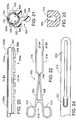
- FIG. 6Ais a perspective view of a surgical system in accordance with a preferred embodiment of a present invention.
- FIG. 6Bis a plan view of a portion of a surgical probe in accordance with a preferred embodiment of a present invention.
- FIG. 7is a perspective view of a surgical system in accordance with a preferred embodiment of a present invention.
- FIG. 8is a top view of a suction device in accordance with a preferred embodiment of a present invention.
- FIG. 9is a side view of the suction device illustrated in FIG. 8 .
- FIG. 10is a bottom view of the suction device illustrated in FIG. 8 .
- FIG. 11is a partial section view taken along line 11 - 11 in FIG. 9 .
- FIG. 12is a section view taken along line 12 - 12 in FIG. 10 .
- FIG. 13is a section view taken along line 13 - 13 in FIG. 10 .
- FIG. 14is a bottom view of showing a portion of the surgical system illustrated in FIG. 7 .
- FIG. 15is a partial section view taken along line 15 - 15 in FIG. 14 .
- FIG. 16is a perspective view of a surgical system in accordance with a preferred embodiment of a present invention.
- FIG. 17is a plan view of a tissue coagulation and stimulation assembly in accordance with a preferred embodiment of a present invention.
- FIG. 18is a section view taken along line 18 - 18 in FIG. 17 .
- FIG. 19is a section view taken along line 19 - 19 in FIG. 17 .
- FIG. 20is an enlarged view of a portion of the tissue coagulation and stimulation assembly illustrated in FIG. 17 .
- FIG. 21is a section view taken along line 21 - 21 in FIG. 20 .
- FIG. 22is a plan view of a clamp in accordance with a preferred embodiment of a present invention.
- FIG. 23is a section view taken along line 23 - 23 in FIG. 22 .
- FIG. 24is a top view of a portion of the clamp illustrated in FIG. 22 .
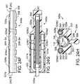
- FIG. 24Ais a side view of a portion of a tissue coagulation and stimulation assembly in accordance with one embodiment of a present invention.
- FIG. 24Bis a side view of a portion of a tissue coagulation and stimulation assembly in accordance with one embodiment of a present invention.
- FIG. 24Cis an enlarged view of a portion of a tissue coagulation and stimulation assembly in accordance with one embodiment of a present invention.
- FIG. 24Dis a section view taken along line 24 D- 24 D in FIG. 24C .
- FIG. 24Eis a section view taken along line 24 E- 24 E in FIG. 24C .
- FIG. 24Fis an enlarged view of a portion of the tissue coagulation and stimulation assembly illustrated in FIG. 24C .
- FIG. 24Gis partial section view taken along line 24 G- 24 G in FIG. 24F .
- FIG. 24His a section view taken along line 24 H- 24 H in FIG. 24F .
- FIG. 25is a perspective view of a surgical system in accordance with a preferred embodiment of a present invention.
- FIG. 26is a section view taken along line 26 - 26 in FIG. 25 .
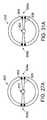
- FIG. 27is an end view of a probe in accordance with one embodiment of a present invention.
- FIG. 27Ais an end view of a probe in accordance with one embodiment of a present invention.
- FIG. 28is a section view taken along line 28 - 28 in FIG. 27 .
- FIG. 29is a perspective view of a surgical system in accordance with a preferred embodiment of a present invention.
- FIG. 30is a section view taken along line 30 - 30 in FIG. 29 .
- FIG. 31is an end view of a probe in accordance with one embodiment of a present invention.
- FIG. 31Ais an end view of a probe in accordance with one embodiment of a present invention.
- FIG. 32is a section view taken along line 32 - 32 in FIG. 31 .
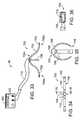
- FIG. 33is a perspective view of a surgical system in accordance with a preferred embodiment of a present invention.
- FIG. 34is a top view of a self-anchoring device in accordance with a preferred embodiment of a present invention.
- FIG. 35is a section view taken along line 35 - 35 in FIG. 34 .
- FIG. 36is an enlarged section view taken along line 35 - 35 in FIG. 34 .
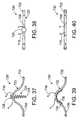
- FIG. 37is a side view of a self-anchoring device in accordance with a preferred embodiment of a present invention.
- FIG. 38is a top view of the device illustrated in FIG. 37 .
- FIG. 39is a side view of a self-anchoring device in accordance with a preferred embodiment of a present invention.
- FIG. 40is a top view of the device illustrated in FIG. 39 .
- Surgical devices in accordance with the present inventionsinclude one or more tissue coagulation elements and/or one or more tissue stimulation elements.
- the tissue coagulation elementsmay be used to, for example, form therapeutic lesions and the tissue stimulation elements may be used to, for example, test whether or not the desired therapeutic lesion has been formed.
- the stimulation elementsmay also be used to stimulate tissue and sense electrical activity in tissue (such as by pacing and recording) during a surgical procedure.
- the surgical devicesmay be used in conjunction with power supply and control apparatus that supply and control power to the tissue coagulation elements in bipolar and/or unipolar modes.
- the surgical devicesmay also be used in conjunction with tissue stimulation apparatus, such as pacing and recording apparatus, which supply power that stimulates (but does not coagulate) tissue.
- Tissue stimulationmay be used to confirm whether or not a therapeutic lesion has been formed by, for example, supplying tissue stimulation energy on one side of a lesion and/or monitoring tissue (either electrically or visually) on the other side of the lesion. Tissue stimulation may also be used to determine lesion depth and, correspondingly, whether or not a lesion is transmural.
- an exemplary surgical system 10in accordance with one embodiment of a present invention includes a surgical probe 100 , a power supply and control apparatus 200 , and a tissue stimulation apparatus 300 .
- the power supply and control apparatus 200 and tissue stimulation apparatus 300are discussed in Sections V and VI below.
- the surgical probe 100includes a relatively short shaft 102 with a proximal section 104 , which is connected to a handle 106 , and a distal section 108 , on which coagulation electrodes 110 are supported.
- the coagulation electrodes 110are discussed in Section V below.
- the distal section 108also supports tissue stimulation electrodes 112 and 114 .
- the tissue stimulation electrodes 112 and 114which are discussed in Section VI below, may also be used to sense local tissue activation.
- the exemplary shaft proximal section 104consists of a hypotube 116 , which is either rigid or relatively stiff, and an outer polymer tubing 118 over the hypotube.
- the handle 106preferably consists of two molded handle halves and is provided with strain relief element 120 .
- the shaft proximal section 104 in the illustrated embodimentmay be from 4 inches to 18 inches in length and is preferably 6 inches to 8 inches.
- the shaft distal section 108which is preferably either malleable, somewhat flexible or some combination thereof, may be from 1 inch to 10 inches in length and is preferably 3 to 5 inches.
- the phrase “relatively stiff”means that the shaft (or distal section or other structural element) is either rigid, malleable, or somewhat flexible.
- a rigid shaftcannot be bent.
- a malleable shaftis a shaft that can be readily bent by the physician to a desired shape, without springing back when released, so that it will remain in that shape during the surgical procedure.
- the stiffness of a malleable shaftmust be low enough to allow the shaft to be bent, but high enough to resist bending when the forces associated with a surgical procedure are applied to the shaft.
- a somewhat flexible shaftwill bend and spring back when released.
- the force required to bend the shaftmust be substantial.
- Rigid and somewhat flexible shaftsare preferably formed from stainless steel, while malleable shafts are formed from annealed stainless steel. Additional information concerning “relatively stiff” shafts is provided in U.S. Pat. No. 6,142,994, which is incorporated herein by reference.
- the hypotube 116may be a heat treated malleable hypotube. By selectively heat treating certain portions of the hypotube, one section of the hypotube can be made more malleable than the other.
- the outer tubing 118may be formed from Pebax® material, polyurethane, or other suitable materials.
- the shaft distal section 108can be either somewhat flexible, in that it will conform to a surface against which it is pressed and then spring back to its original shape when removed from the surface, malleable, or some combination thereof.
- the distal section 108includes a malleable proximal portion and a flexible distal portion.
- the relative lengths of the portionsmay vary to suit particular applications, the malleable proximal portion and a flexible distal portion are equal in length in the illustrated embodiment.
- the exemplary shaft distal section 108includes an outer member 122 that carries the electrodes 110 - 114 .
- the outer member 122is a flexible tubular structure which has an outer diameter that is, depending on the diameter of the electrodes 110 and 112 , typically between about 2 mm and about 4 mm.
- Suitable support structure materialsinclude, for example, flexible biocompatible thermoplastic tubing such as unbraided Pebax® material, polyethylene, or polyurethane tubing.
- the exemplary malleable portionincludes a mandrel 124 ( FIG. 4 ) made of a suitably malleable material, such as annealed stainless steel or beryllium copper, that may be fixed directly within the distal end of the shaft's hypotube 116 and secured by, for example, soldering, spot welding or adhesives.
- a suitably malleable materialsuch as annealed stainless steel or beryllium copper
- Sufficient spaceshould be provided to allow passage of the power lines 126 , which are connected to the coagulation electrodes 110 , the temperature sensor signal lines 128 , which are connected to temperature sensors 130 ( FIG. 5 ) such as thermocouples or thermistors, and signal lines 132 , which are connected to the tissue stimulation electrodes 112 and 114 .
- the power lines 126may be used to transmit energy from the power supply and control apparatus 200 to the coagulation electrodes 110 , while signal lines 128 return temperature information from the temperature sensors 130 to the power supply and control apparatus.
- the signal lines 132may be used to transmit tissue stimulation energy from the tissue stimulation apparatus 300 to the stimulation electrodes 112 and 114 .
- the signal lines 132may also be used to transmit the signals associated with local electrical activity when the tissue stimulation electrode 112 and 114 are used for sensing.
- An insulating sleeve 134is placed over the mandrel 124 to protect the power lines 126 , temperature sensor signal lines 128 and signal lines 132 .
- the insulating sleeve 134is preferably formed from Pebax® material, polyurethane, or other suitable materials.
- a spring member 136which is preferably either a solid flat wire spring ( FIG. 5 ), a round wire, or a three leaf flat wire Nitinol® spring, is connected to the distal end of the mandrel 124 with a crimp tube or other suitable instrumentality.
- the distal end of the spring member 136is connected to the electrode 114 by, for example, an adhesive that will also electrically insulate the spring member from the electrode.
- the electrode 114is also secured to the distal end of the outer member 122 .
- Other spring membersformed from materials such as 17-7 or carpenter's steel, may also be used.
- the spring member 136is also enclosed within the insulating sleeve 134 .
- the spring member 136may be pre-stressed so that the distal tip is pre-bent into a desired shape. Additional details concerning distal sections that have a malleable proximal portion and a flexible distal portion are provided in U.S. Pat. No. 6,464,700, which is incorporated herein by reference.
- the distal section 108may be formed by a hypotube that is simply a continuation of the shaft hypotube 116 covered by a continuation of the outer tubing 118 .
- the distal end hypotubecan also be a separate element connected to the shaft hypotube 116 , if it is desired that the distal end hypotube have different stiffness (or bending) properties than the shaft hypotube.
- the distal section 108may be made malleable from end to end by eliminating the spring member 136 and extending the malleable mandrel 124 to the electrode 114 .
- the distal section 108may be made flexible from end to end by eliminating the malleable mandrel 124 and extending the spring member 136 from the hypotube 116 to the electrode 114 .
- the power lines 126 and signal lines 128extend from the coagulation electrodes 110 and temperature sensors 130 to a connector (such as the exemplary PC board 138 ) that is carried by the handle 106 .
- the handle 106also includes a port 140 that is configured to receive a connector, such as the connector 206 ( FIG. 1 ) from the power supply and control apparatus 200 , for connection to the PC board 138 . Openings 142 and 144 are provided for the signal lines 132 .
- the exemplary surgical system 11which is illustrated in FIGS. 6A and 6B , includes a surgical probe 101 , a power supply and control apparatus 200 , a tissue stimulation apparatus 300 and an EP recording apparatus 301 .
- the power supply and control apparatus 200is discussed in Section V, while the tissue stimulation apparatus 300 and EP recording apparatus 301 are discussed in Section. VI.
- the exemplary surgical probe 101is essentially identical to the surgical probe 100 and similar elements are represented by similar reference numerals.
- a plurality of stimulation electrodes 112are located along the length of the shaft distal portion 108 .
- a stimulation electrode 112is located between each of the coagulation electrodes 110 .
- Electrodes 112There is also a stimulation electrode 112 proximal of the proximal-most coagulation electrode 110 and a stimulation electrode 112 distal of the distal-most coagulation electrode 110 .
- a stimulation electrode 114is also provided on the distal end of the probe.
- Signal lines 132which are connected to the tissue stimulation electrodes 112 and 114 , extend though a cable 115 and are connected to the EP recording apparatus 301 with a connector 117 .
- pairs of stimulation electrodes 112may be located between each of the coagulation electrodes 110 , proximal of the proximal-most coagulation electrode, and distal of the distal-most coagulation electrode.
- a stimulation electrode 114 on the distal end of the probemay also be provided.
- an exemplary surgical system 20in accordance with one embodiment of a present invention includes a surgical probe 100 ′, a power supply and control apparatus 200 , a tissue stimulation apparatus 300 and an EP recording apparatus 301 .
- the power supply and control apparatus 200is discussed in Section V, while the tissue stimulation apparatus 300 and EP recording apparatus 301 are discussed in Section VI.
- the exemplary systemis also provided with a suction apparatus 400 that includes a suction source 402 and a suction device 404 that may be removably secured to the distal section 108 of the surgical probe 100 ′.
- the suction device 404is connected to the suction source 402 by a flexible tube 406 .
- the suction device 404When the suction source 402 is actuated, the suction device 404 will fix the position of the distal section of the surgical probe 100 ′ relative to the target tissue. Additionally, depending on the rigidity of the suction device 404 and the rigidity of the tissue, the applied vacuum may also cause the tissue and electrodes 110 on the distal section 108 to come into contact with one another because portions of the suction device will deflect, portions of the tissue surface will deflect, or portions of both the suction device and the tissue surface will deflect.
- the surgical probe 100 ′is substantially identical to surgical probe 100 and similar elements are represented by similar reference numerals.
- Surgical probe 100 ′does not, however, include the tissue stimulation electrodes 112 and 114 .
- the suction device 404is provided with tissue stimulation electrodes 426 and, in some instances, sensing electrodes 428 .
- the tissue stimulation and sensing electrodes 426 and 428which are held firmly against tissue when the suction source 402 is activated, are discussed in Section VI below.
- the exemplary suction source 402may be any suitable device that is capable of supplying the desired partial vacuum, which will typically range from about 200 mmHg to about 700 mmHg.
- the exemplary suction device 404includes a main body 407 , a pair of internal suction lines 408 and a plurality of individual suction ports 410 .
- the suction tube 406may be connected to the internal suction lines 408 by a connector 412 such as, for example, the illustrated Luer connector.
- the suction ports 410are respectively connected to the internal suction lines 408 by a plurality of apertures 414 .
- the suction ports 410are also formed in the curved bottom surface 416 (or “bottom wall”) of the main body 407 and define respective suction regions 418 ( FIG. 12 ). During use, the curved bottom surface will form a seal with the tissue surface and air within the suction regions 418 will be drawn through the apertures 414 , thereby causing the suction device 404 to adhere to the tissue surface.
- the suction device 404also includes a connector that enables it to be removably secured to the distal portion 108 of the surgical probe 100 ′.
- the connector in the exemplary embodimentis a slot 420 into which the surgical probe distal portion 108 may be inserted.
- the slot 420is generally semi-circular in cross-section and extends between about 180 to 360 degrees, and preferably about 300 degrees.
- the diameter of the slot 420will preferably be about the same as the diameter of the surgical probe distal portion 108 .
- the distal portion 108may be removably snap fit into the slot 420 .
- the surgical probe distal portion 108once the surgical probe distal portion 108 is within the slot 420 , it may be advanced distally toward the suction device nose 422 and into an aperture 424 for anchoring ( FIGS. 14 and 15 ).
- the specific size and shape of the suction device 404will, of course, depend on the intended application, as will the choice of materials. Although the present inventions are not limited to any particular sizes, shapes or materials, one exemplary implementation that is especially well suited for cardiac treatment and use with the above-described surgical probe 100 ′ is described hereafter.
- the suction device 404is formed, preferably by molding, from a soft, flexible biocompatible material such as silicone rubber or urethane that is capable of withstanding temperatures up to 120° C. without melting or burning. When molded, the suction device 404 will be an integrally formed (i.e. one piece) structure, although some or all of the connector 412 may be added after molding depending on the type of connector employed.
- the overall length of the suction device 404not including the connector 412 , will be slightly longer than the shaft distal portion 108 , e.g. about 10 cm in an exemplary implementation where the distal portion is about 9 cm.
- the exemplary suction ports 410are generally concave and elliptical in shape and have a major diameter of about 5 mm, a minor diameter of about 3 mm, a depth of about 2 mm.
- the spacingcorresponds to the spacing of the electrodes on the associated probe.
- the exemplary elliptical (i.e. 5 mm ⁇ 3 mm ⁇ 2 mm) suction portsmay be spaced apart by about 6 mm center-to-center.
- the distance between the bottom of the slot 420 and the bottom of the main body 407is about 5 mm.
- the stimulation electrodes in the exemplary implementationare connected to signal lines 430 that extend from the stimulation electrodes, around the main body 407 , to a signal line bundle 432 on the top of the main body.
- signal lines 434extend from the sensing electrodes 428 to a signal line bundle 436 .
- a silicone rubber overmold 438may be used to cover the individual signal lines and signal line bundles in those instances where the main body 407 is formed from silicone rubber.
- the signal lines and signal line bundlesmay be held in place with an elastic polyurethane adhesive.
- the signal lines in the bundles 432 and 436pass through a cable 440 ( FIG. 7 ) and are connected to the EP recording apparatus 301 by a connector 442 .
- the EP recording apparatus 301is connected to, and directs the tissue stimulation and recording associated with, the tissue stimulation apparatus 300 .
- the exemplary suction device 404may be secured to the distal portion of a conventional electrophysiology catheter. The distal portion of the catheter and suction device 404 could then be used to directly place electrodes against tissue during a surgical procedure.
- the exemplary suction device 404may also be permanently secured to a surgical probe or catheter by overmolding the suction device onto the surgical probe or catheter.
- an exemplary surgical system 30in accordance with one embodiment of a present invention includes an electrophysiology clamp apparatus 500 , a power supply and control apparatus 200 , and a tissue stimulation apparatus 300 .
- the power supply and control apparatus 200 and tissue stimulation apparatus 300are discussed in Sections V and VI below.
- the electrophysiology clamp apparatus 500includes a clamp and a tissue coagulation and stimulation assembly that may be secured to the clamp.
- clampincludes, but is not limited to, clamps, clips, forceps, hemostats, and any other surgical device that includes a pair of opposable clamp members that hold tissue, at least one of which is movable relative to the other.
- the clamp membersare connected to a scissors-like arrangement including a pair of handle supporting arms that are pivotably connected to one another.
- the clamp membersare secured to one end of the arms and the handles are secured to the other end.
- Certain clamps that are particularly useful in minimally invasive proceduresalso include a pair of handles and a pair of clamp members.
- the clamp members and handlesare not mounted on the opposite ends of the same arm. Instead, the handles are carried by one end of an elongate housing and the clamp members are carried by the other.
- a suitable mechanical linkage located within the housingcauses the clamp members to move relative to one another in response to movement of the handles.
- the clamp membersmay be linear or have a predefined curvature that is optimized for a particular surgical procedure or portion thereof.
- the clamp membersmay also be rigid or malleable.
- the clamp 502includes a pair of rigid arms 504 and 506 that are pivotably connected to one another by a pin 508 .
- the proximal ends of the arms 504 and 506are respectively connected to a pair handle members 510 and 512 , while the distal ends are respectively connected to a pair of clamp members 514 and 516 .
- the clamp members 514 and 516may be rigid or malleable and, if rigid, may be linear or have a pre-shaped curvature.
- a locking device 518locks the clamp in the closed orientation, and prevents the clamp members 514 and 516 from coming any closer to one another than is illustrated in FIG. 22 , thereby defining a predetermined spacing between the clamp members.
- the clamp 502is also configured for use with a pair of soft, deformable inserts (not shown) that may be removably carried by the clamp members 514 and 516 and allow the clamp to firmly grip a bodily structure without damaging the structure.
- the clamp members 514 and 516each include a slot 520 ( FIGS. 23 and 24 ) that is provided with a sloped inlet area 522 and the inserts include mating structures that are removably friction fit within the slots.
- the present tissue coagulation and stimulation assembliesmay be mounted on the clamp members in place of the inserts.
- tissue coagulation and stimulation assemblywhich is generally represented by reference numeral 524 in FIGS. 16-19 , includes first and second tissue coagulation electrodes 526 a and 526 b , which are discussed in Section V below, and first and second tissue stimulation electrodes 528 a and 528 b , which are discussed in Section VI below.
- first and second tissue stimulation electrodes 528 a and 528 bwhich are discussed in Section VI below.
- the electrodesare carried on support structures 530 a and 530 b , which are connected to a flexible cable 532 by a molded plastic junction 534 .
- the first and second coagulation electrodes 526 a and 526 bare also relatively long electrodes (e.g. about 3 to 8 cm) and, to that end, power lines 536 are connected to each longitudinal end of the first tissue coagulation electrode 526 a and return lines 538 are connected to each longitudinal end of the second tissue coagulation electrode 526 b . It should be noted that although the return lines 538 may be used to return power when the surgical system 30 is operating in a bipolar mode, the return lines may also be used to supply power when the system is operating in a unipolar mode.
- the tissue stimulation electrode 528 ais connected to a signal line 540
- the tissue stimulation electrode 528 bis connected to a signal line 542 .
- the signal lines 540 and 542may be used for transmission and return, respectively, when the system is being operated in a bipolar mode, and both may be used for transmission when the system is being operated in unipolar mode.
- the first and second tissue stimulation electrodes 528 a and 528 b , as well as the signal lines 540 and 542may also be used to transmit signals when the stimulation electrodes are used for sensing and recording purposes.
- a plurality of temperature sensors 130such as thermocouples or thermistors are carried on the support structures 530 a and 530 b .
- Signal lines 544are connected to each of the temperature sensors 130 .
- first and tissue second coagulation electrodes 526 a and 526 bmay be split into two electrodes that are about 1.5 cm to 4 cm in length and separated by about 1 to 3 mm.
- each electrodewill be connected to a single power or return line and two temperature sensors 130 will be associated with each electrode.
- the power supply lines 536may be used to transmit energy from the power supply and control apparatus 200 to the coagulation electrode 526 a (which is returned by way of coagulation electrode 526 b and return lines 538 ), while the signal lines 544 return temperature information from the temperature sensors 130 to the power supply and control apparatus.
- the signal line 540may be used to transmit tissue stimulation energy from the tissue stimulation apparatus 300 to the stimulation electrode 528 a .
- the stimulation energyis returned to the tissue stimulation apparatus 300 by way of the stimulation electrode 528 b and signal line 542 .
- the power supply and return lines 536 and 538 and signal lines 540 - 544extend from the electrodes 526 a - 528 b and temperature sensors 130 , through the cable 532 , to a handle 545 .
- the power supply and return lines 536 and 538 and signal lines 544are connected to a PC board 546 that is carried by the handle 545 .
- the handle 545also includes a port (not shown) for a connector 206 ′ from the power supply and control apparatus 200 which connects to the PC board 546 , and openings (not shown) for signal lines 540 and 542 , which are connected to the tissue stimulation apparatus 300 .
- the exemplary tissue coagulation and stimulation assembly 524also includes a pair of base members 548 a and 548 b which are used to connect the assembly to the clamp 502 .
- the exemplary energy transmission and stimulation assembly 524is configured such that the electrodes 526 a and 526 b will be parallel to one another as well as relatively close to one another (i.e. a spacing of about 1-10 mm) when the clamp 502 is in the closed orientation.
- the stimulation electrodes 528 a and 528 bwill typically be about 5 mm to 50 mm apart when the clamp 502 is opened (in full or in part).
- the base member 548 aincludes a main portion 550 , with a groove 552 that is configured to receive the support structure 530 a and electrode 526 a , and a connector 554 that is configured to removably mate with the slot 520 in the clamp 502 .
- the configuration of the base member 548 bis identical to that of the base member 548 a in the illustrated embodiment.
- About 20% of the electrode surfacei.e. about 75° of the 360° circumference) is exposed in the illustrated embodiment.
- Adhesivemay be used to hold the electrode 526 a and support structure 530 a in place.
- the exemplary connector 554is provided with a relatively thin portion 556 and a relatively wide portion 558 , which may consist of a plurality of spaced members (as shown) or an elongate unitary structure, in order to correspond to the shape of the slot 520 .
- the base members 548 a and 548 bare preferably formed from polyurethane.
- the length of the base members in the exemplary energy transmission assemblieswill vary according to the intended application. In the area of cardiovascular treatments, it is anticipated that suitable lengths will range from, but are not limited to, about 4 cm to about 10 cm. In the exemplary implementation, where the electrodes 526 a and 526 b are preferably about 6.4 cm, the base members 548 a and 548 b will be about 6.6 cm.
- the exemplary clamp apparatus 500is not limited to the exemplary implementation described above and is susceptible to a wide variety of modifications.
- the tissue coagulation and stimulation assemblymay be modified such that the position of the first and second tissue stimulation electrodes 528 a and 528 b relative to the first and tissue second coagulation electrodes 526 a and 526 b and/or the distal ends of the base members may be varied, as they are in base members 548 a ′ and 548 a′′.
- tissue coagulation and stimulation assemblywherein a plurality of stimulation electrodes are associated with one (or both) of coagulation electrodes.
- the stimulation electrodesmay, for example, be located on opposite sides of a coagulation electrode so that the stimulation electrodes will be on opposite side of the lesion for stimulation and sensing purposes.
- One such tissue coagulation and stimulation assemblyis generally represented by reference numeral 524 ′ and is illustrated in FIGS. 24C-H .
- the tissue coagulation and stimulation assembly 524 ′is substantially similar to the tissue coagulation and stimulation assembly 524 illustrated in FIGS. 17-21 and similar elements are represented by similar reference numerals.
- pairs of stimulation electrodes 529 a 1 / 529 a 2 and 529 b 1 / 529 b 2are positioned on opposite sides of the coagulation electrode 526 a .
- the spacing between the stimulation electrodes 529 a 1 / 529 a 2 and 529 b 1 / 529 b 2which are discussed in Section VI below, and the coagulation electrode 526 a will typically be about 1 mm.
- the coagulation electrodes 526 a and 526 bare carried on support structures 530 a and 530 b .
- the stimulation electrodes 529 a 1 / 529 a 2 and 529 b 1 / 529 b 2are carried on support structures 531 a and 531 b.
- the exemplary tissue coagulation and stimulation assembly 524 ′also includes a pair of base members 549 a and 549 b which are used to connect the assembly to the clamp 502 in the manner described above with reference to base members 548 a and 548 b .
- the base member 549 aincludes a main portion 551 , with a groove 552 that is configured to receive the support structure 530 a and electrode 526 a , and a pair of grooves 553 that are configured to receive the stimulation electrodes 529 a 1 / 529 a 2 and 529 b 1 / 529 b 2 and support structures 531 a and 531 b .
- a connector 554is configured to removably mate with the slot 520 in the clamp 502 .
- the configuration of the base member 549 bis identical to that of the base member 548 b in the illustrated embodiment.
- the base member 549 bmay be configured to carry stimulation electrodes in the same manner as base member 549 a .
- Still another alternativeis to configure the assembly such that stimulation electrodes 529 a 1 / 529 a 2 are carried base member 549 a , stimulation electrodes 529 b 1 / 529 b 2 are carried base member 549 b , and stimulation electrodes 529 a 1 / 529 a 2 and stimulation electrodes 529 b 1 / 529 b 2 are on opposite side of the coagulation electrodes.
- the tissue stimulation electrodes 529 a 1 / 529 a 2are connected to respective signal lines 540 and 542 , as are the tissue stimulation electrodes 529 b 1 / 529 b 2 .
- the signal lines 540 and 542may be used for transmission and/or return depending upon the manner in which the electrodes are being used.
- the stimulation electrodes 529 a 1 / 529 a 2may be used in bipolar mode to transmit stimulation energy and the stimulation electrodes 529 b 1 / 529 b 2 may be used in bipolar mode to sense local activation.
- the clamp and the tissue coagulation and stimulation assemblies described abovemay be combined into an integral unit that cannot be readily separated.
- the base membersmay be molded onto the clamp members. Such base members would, for example, extend completely around the each clamp member and/or include portions that are molded into the slots.
- coagulation electrodesadapted to transmit RF energy are employed.
- other types of coagulation elementssuch as such as lumens for chemical ablation, laser arrays, ultrasonic transducers, microwave electrodes, ohmically heated hot wires, and the like may be substituted for the coagulation electrodes.
- Coagulation electrodesmay be arranged as a series of spaced electrodes or, alternatively, a single elongate coagulation electrode may be employed.
- the exemplary surgical probes 100 , 100 ′ and 101 illustrated in FIGS. 1-15each include seven spaced coagulation electrodes 110
- the various clamp apparatus 500 illustrated in FIGS. 16-24Hincludes a single electrode 526 a / 526 b carried on each of the clamp members 514 and 516 .
- the coagulation electrodesare preferably in the form of wound, spiral closed coils.
- the coilsare made of electrically conducting material, like copper alloy, platinum, or stainless steel, or compositions such as drawn-filled tubing (e.g. a copper core with a platinum jacket).
- the electrically conducting material of the coilscan be further coated with platinum-iridium or gold to improve its conduction properties and biocompatibility.
- Preferred coil coagulation electrodesare disclosed in U.S. Pat. Nos. 5,797,905 and 6,245,068.
- the coagulation electrodes 110may be in the form of solid rings of conductive material, like platinum, or can comprise a conductive material, like platinum-iridium or gold, coated upon the device using conventional coating techniques or an ion beam assisted deposition (IBAD) process. For better adherence, an undercoating of nickel, silver or titanium can be applied.
- the coagulation electrodescan also be in the form of helical ribbons.
- the electrodescan also be formed with a conductive ink compound that is pad printed onto a non-conductive tubular body.
- a preferred conductive ink compoundis a silver-based flexible adhesive conductive ink (polyurethane binder), however other metal-based adhesive conductive inks such as platinum-based, gold-based, copper-based, etc., may also be used to form electrodes. Such inks are more flexible than epoxy-based inks. Open coil electrodes may also be employed for coagulation.
- the exemplary flexible coagulation electrodes 110 carried by the surgical probes 100 , 100 ′ and 101 illustrated in FIGS. 1-15are preferably about 4 mm to about 20 mm in length.
- the electrodesare 12.5 mm in length with 1 mm to 3 mm spacing, which will result the creation of continuous lesion patterns in tissue when coagulation energy is applied simultaneously from adjacent electrodes through tissue to an indifferent electrode.
- the length of the each electrodecan vary from about 2 mm to about 10 mm. Using multiple rigid electrodes longer than about 10 mm each adversely effects the overall flexibility of the device, while electrodes having lengths of less than about 2 mm do not consistently form the desired continuous lesion patterns.
- the diameterwill typically be about 3 mm.
- the lengthis preferably between about 2 cm and 8 cm in those instances where power is supplied at both longitudinal ends of each electrode, and the end to end resistance is about 5 ohm to about 15 ohm.
- the diameter of the electrodes described abovepreferably ranges from about 1.5 mm to about 3 mm for cardiovascular applications and, in one preferred implementation, the outer diameter is about 2 mm.
- the temperature sensors 130are preferably located within a linear channel, such as the channel 131 in FIG. 5 , which is formed in the shaft distal portion 108 ( FIGS. 1-15 ) or in the channel 131 in FIG. 21 , which is formed in the support structures 530 a and 530 b ( FIGS. 16-21 and 24 C- 24 H).
- the linear channelinsures that the temperature sensors will all face in the same direction (e.g. facing tissue) and be arranged in linear fashion. This arrangement results in more accurate temperature readings which, in turn, results in better temperature control.
- the actual tissue temperaturewill more accurately correspond to the temperature set by the physician on the power supply and control device, thereby providing the physician with better control of the lesion creation process and reducing the likelihood that embolic materials will be formed.
- a reference thermocouplemay also be provided.
- the power supply and control system 200includes an electrosurgical unit (“ESU”) 202 that supplies and controls RF power.
- ESUelectrosurgical unit
- a suitable ESUis the Model 4810 ESU sold by Boston Scientific Corporation of Natick, Mass., which is capable of supplying and controlling power on an electrode-by-electrode basis. This is sometimes referred to as “multi-channel control.”
- the ESU 202transmits energy to the coagulation electrodes and receives signal from the temperature sensors by way of a cable 204 and a connector 206 , which may be connected to the PC board on the surgical probe or clamp in the manner described above.
- the amount of power required to coagulate tissueranges from 5 to 150 W.
- the exemplary ESU 202is operable in a bipolar mode, where tissue coagulation energy emitted by one of the coagulation electrodes is returned through one of the other coagulation electrodes, and a unipolar mode, where the tissue coagulation energy emitted by the coagulation electrodes is returned through one or more indifferent electrodes 208 that are externally attached to the skin of the patient with a patch, or one or more electrodes (not shown) that are positioned in the blood pool, and a cable 210 .
- Information concerning suitable temperature sensing and RF power supply and controlis disclosed in U.S. Pat. Nos. 5,456,682, 5,582,609 and 5,755,715.
- Another alternativeis to supply power in the combined bipolar/unipolar mode described in U.S. application Ser. No. 10/368,108, which is entitled “Power Supply And Control Apparatus And Electrophysiology Systems For Use With Same” and incorporated herein by reference.
- a single power line 126is connected to each coagulation electrode 110 .
- the ESU 202individually powers and controls each coagulation electrode 110 based on the hottest of the two measured temperatures at that particular electrode.
- first and second power lines 536are respectively connected to the longitudinal ends of the coagulation electrode 526 a
- first and second return lines 538are respectively connected to the longitudinal ends of the coagulation electrode 526 b
- two pairs of temperature sensors 130i.e. four temperature sensors
- Each temperature sensor pairincludes one temperature sensor 130 at a longitudinal end of the associated coagulation electrode and one temperature sensor located a distance equal to about 1 ⁇ 3 of the total electrode length from the longitudinal end.
- the ESU 202will typically be operated in bipolar mode and energy supplied to the coagulation electrode 526 a will be returned to the ESU by way of the coagulation electrode 526 b .
- the ESU connector 206 ′is connected to the power supply and return lines 536 and 538 .
- the ESU 202 in the exemplary surgical system 30may be used to individually power and control two portions of the coagulation electrode 526 a (one portion on either side of the longitudinal mid-point of the electrode) during a lesion formation procedure. Power to each portion, which has one power line 536 connected thereto and two temperature sensors 130 associated therewith, is controlled based on the highest of the two temperatures sensed by the two temperature sensors associated with that portion. Additional details concerning this power supply and control technique are provided in U.S. application Ser. No. 10/255,025, which is entitled “Electrophysiology Electrode Having Multiple Power Connections And Electrophysiology Devices Including The Same” and incorporated herein by reference.
- the exemplary ESU 202is also provided with power output and return connectors 212 and 214 ( FIGS. 1 , 6 A, 7 and 16 ), for connection to corresponding connectors on the power output and return cables 204 and 210 , that have different configurations in order to prevent improper connections.
- the exemplary surgical systems illustrated in FIGS. 1-24Hmay also be used to determine whether or not therapeutic lesions have been properly formed by, for example, supplying tissue stimulation energy on one side of a lesion. The tissue on the other side of the lesion may then be monitored to determine whether an excitation block (typically the result of a continuous transmural lesion) has been formed in the target tissue. Tissue stimulation energy may also be used to determine lesion depth, which in turn, allows the physician to determine whether or not a lesion is transmural.
- the tissue stimulation energyis provided by a tissue stimulation apparatus 300 that is capable of providing a pulse of energy that stimulates (but does not coagulate) tissue.
- One exemplary tissue stimulation apparatus 300is a conventional pacing apparatus, such as the Medtronic Model Nos. 5330 and 5388 external pulse generators.
- An ECG machinethat is capable of monitoring and recording electrical impulses sensed by electrodes may also be provided.
- the power delivered to tissue for stimulation purposeswill typically be significantly less than that which would form a transmural or otherwise therapeutic lesion in tissue.
- an exemplary stimulation energy deliverywould consist of two stimulation pulses per second, each pulse being 1 millisecond. The maximum amplitude would be 20 mA, which would create 1 V, for a total power delivery of 40 ⁇ W.
- an exemplary stimulation energy deliverywould consist of two stimulation pulses per second, each pulse being 1 millisecond.
- the maximum amplitudewould be 10 mA, which would create 0.5 V, for a total power delivery of 10 ⁇ W.
- the amount of power required to coagulate tissueranges from 5 to 150 W.
- connectors 302both transmission and return
- Suitable connectorsinclude, for example, 2 mm Hirshman pins.
- the connectors 302may be individually connected to the tissue stimulation apparatus 300 (as shown) or combined into a single unit.
- the configuration of the connectors 302will also typically be different than the ESU connectors 212 and 214 to prevent improper connections.
- FIGS. 6A and 6Bthere are far more stimulation electrodes and a single connector 117 is used to connect the stimulation electrodes to the EP recording apparatus 301 .
- FIGS. 6A and 6Bthere are far more stimulation electrodes and a single connector 117 is used to connect the stimulation electrodes to the EP recording apparatus 301 .
- FIGS. 6A and 6Bthere are far more stimulation electrodes and a single connector 117 is used to connect the stimulation electrodes to the EP recording apparatus 301 .
- FIGS. 6A and 6Bthere are far more stimulation electrodes and a single connector 117 is used to connect the stimulation electrodes to the EP recording apparatus 301
- a single connector 442is used to connect the electrodes to the EP recording apparatus 301 .
- a suitable electrophysiology (EP) recording apparatusis the Prucka CardioLab 7000® from GE Medical Systems.
- the configuration of the connectors 117 and 442will be different than the ESU connectors 212 and 214 to prevent improper connections.
- tissue stimulation apparatus 300may be incorporated into the ESU 202 .
- ESU and associated surgical devicesshould be configured such that coagulation electrodes will only receive coagulation energy and the stimulation electrodes will only receive stimulation energy.
- thismay be accomplished with different connector configurations.
- the functionality of the tissue stimulation apparatus 300 and the EP recording apparatus 301may also be combined into a single device.
- the present surgical systemsmay be used to test the effectiveness of a lesion as follows.
- the physicianmay use the same surgical device that was used to form the lesion (e.g. the surgical probe, surgical probe and suction device, or clamp based electrophysiology device) to perform a lesion evaluation.
- the stimulation electrodes that are provided on surgical devicesmay be used to stimulate tissue on one side of a lesion by pacing at a higher rate than normal (e.g. 120 beats/minute).
- the local activation, if any, on the other side of the lesionwill indicate whether or not the excitation block is incomplete.
- the stimulation electrodesmay also be used to sense tissue within an isolated tissue region around which a lesion has been formed. Local activation within the isolated region from the heart's natural stimulation is indicative of a gap in the lesion. Additionally, the stimulation electrodes may be used to determine lesion depth.
- tissue stimulation electrodeson the same surgical device as the tissue coagulation electrodes allows the physician to quickly and easily evaluate a lesion after it has been formed.
- the surgical probe 100is provided with a pair of tissue stimulation electrodes 112 and 114 that may be connected to the tissue stimulation apparatus 300 and used to provide stimulation energy.
- the tissue stimulation electrodes 112 and 114may also be used for sensing local tissue activation.
- the stimulation electrodes 112 and 114will operate in a bipolar mode, but may be operated in unipolar mode if desired.
- the stimulation electrodes 112 and 114are typically relatively small (i.e. too small to form transmural myocardial lesions).
- stimulation electrode 112is a ring electrode that is about 0.5 mm to 2 mm in length
- the stimulation electrode 114is a tip electrode that is about 0.5 mm to 2 mm in length
- the spacing therebetweenis about 0.5 mm to 2 mm.
- the stimulation electrode 114may be in the form of a ring electrode.
- Stimulation electrode 112is about 1 mm to 3 mm from the distal-most coagulation electrode 110 .
- the stimulation electrodes 112 and 114may be formed from the same materials as the coagulation electrodes 110 .
- the diameter of the electrodes 112 and 114preferably ranges from about 1.5 mm to about 3 mm for cardiovascular applications and, in one preferred implementation, the outer diameter is about 2 mm.
- the exemplary surgical system 10may be used to test the quality of lesions formed during a lesion formation procedure in a variety of ways.
- the coagulation electrodes 110may be used to form continuous lesions around the pulmonary veins to isolated them from the left atria.
- a first lesionwill be formed around the right pulmonary vein pair and a second lesion will be formed around the left pulmonary vein pair.
- the stimulation electrodes 112 and 114may then be used to provide stimulation energy to the area within the first lesion.
- the tissue on the other side of the lesionmay be monitored (electrically or visually) to determine whether the excitation block formed by the first lesion is complete. A similar procedure may be performed with respect to the second lesion.
- the stimulation electrodes 112 and 114may be used to sense tissue within the area defined by the first lesion to determine whether heart's natural stimulation will produce local activation within the tissue area defined by the lesion. No local activation within the area defined by the lesion is indicative of the formation of a complete excitation block, while local activation is indicative of a gap in the lesion. A similar procedure may be performed with respect to the second lesion. It should also be noted that the surgical system 10 may be used both epicardial and endocardial procedures and that stimulation electrodes 112 and 114 may be used individually in unipolar versions of the aforementioned procedures if desired.
- the tissue stimulation electrodes 112 and 114 in the exemplary surgical probe 101 illustrated in FIGS. 6A and 6Bhave the same configuration as the tissue stimulation electrodes in the surgical probe 100 and the surgical system 11 may be used to test the quality of lesions in the manner described above. Additionally, the surgical system 11 may be used to determine lesion depth and, correspondingly, whether or not a lesion is transmural at various points along the length of the lesion. Stimulation energy may be used to determine lesion depth because non-viable tissue (e.g. coagulated tissue) cannot be stimulated and will not propagate stimulation energy to nearby tissue. As such, when the application of stimulation energy that should stimulate tissue at a known depth fails to do so, and that depth is greater than or equal to the thickness of the body structure, it may be inferred that a transmural lesion has been formed.
- non-viable tissuee.g. coagulated tissue
- a 1 mA stimulation pulsewill typically stimulate viable tissue that is no more than about 2.8 mm from the electrode
- a 2 mA stimulation pulsewill typically stimulate viable tissue that is no more than about 4.0 mm from the electrode
- a 10 mA stimulation pulsewill typically stimulate viable tissue that is no more than about 9.0 mm from the electrode
- a 20 mA stimulation pulsewill typically stimulate viable tissue that is no more than about 13.0 mm from the electrode.
- the amplitude of the stimulation energy pulsesover a range of 1 to 20 mA, it is possible to determine how far viable tissue is from the electrode.
- the left atriumis about 3 mm thick and accordingly, failure to stimulate with a 2 mA stimulation pulse indicates that a transmural lesion has been formed in the vicinity of the stimulation electrode.
- the tissue stimulation electrodes 112are located between the coagulation electrodes 110 and proximal of the proximal-most coagulation electrode, while the stimulation electrode 114 is distal of the distal-most coagulation electrode.
- This arrangementallows the physician to test various points along the length of a lesion when all of the coagulation electrodes 110 are used to form the lesion (without moving the probe).
- the adjacent four tissue stimulation electrodes 112could be used to stimulate tissue to determine whether or not the lesion is transmural.
- the exemplary surgical system 11may be used to test the quality of lesions formed during a lesion formation procedure in a variety of ways.
- the coagulation electrodes 110may be used to form a continuous lesion (e.g. around one or more pulmonary veins, or as part of a pattern of therapeutic lesions).
- the stimulation electrodes 112 and 114may be used to provide stimulation energy to the coagulated tissue.
- the stimulation electrodes 112 and 114which are located along the linear or curvilinear region of coagulated tissue may be individually provided with pulses of stimulation energy.
- the magnitude of the pulseswhich should be chosen so as to correspond to the thickness of the tissue structure, will be about 2 mA in the left atrium example.
- Viable tissue within the left atriummay be monitored (electrically or visually) after each pulse to determine whether the lesion is transmural. More specifically, a lack of local activation within the left atrium from the pulse indicates that the lesion is deep enough (i.e. transmural) in the vicinity of the associated stimulation electrode, while local activation indicates that the lesion is not transmural in the region of the stimulation electrode. In those instances where the lesion (or portion thereof) is not transmural, additional coagulation with the coagulation electrodes 110 , typically at a higher power level than originally employed, may be performed. It should also be noted that the surgical system 11 may be used both epicardial and endocardial procedures.
- the suction device 404is provided with longitudinally extending bipolar pairs of tissue stimulation electrodes 426 and longitudinally extending bipolar pairs of sensing electrodes 428 near the lateral edges of the suction device.
- a plurality of bipolar pairs of stimulation electrodes 426extend along essentially the entire length of one side of the suction device 404
- a plurality of bipolar pairs of sensing electrodes 428extend along essentially the entire length of the other side of the suction device.
- Each bipolar pairis adjacent to one of the suction ports 410 and, accordingly, the electrodes will be held firmly against tissue when suction force is applied.
- the stimulation electrodes 426are located on one side of the slot 420 and the sensing electrodes 428 are located on the other. As such, the tissue stimulation and sensing electrodes 426 and 428 will be on opposite sides of the surgical probe distal section 108 and the coagulation electrodes 110 , as well as on opposite sides of the lesion formed by the coagulation electrodes.
- the number of bipolar pairs of tissue stimulation and sensing electrodes 426 and 428may range from a large number of pairs (as shown) to a single pair tissue stimulation electrodes and a single pair sensing electrodes.
- the single pairsmay be located near the middle (measured longitudinally) of the suction device 404 .
- Another alternativeis unipolar stimulation and sensing.
- single stimulation electrodes(as opposed to a bipolar pair) may be positioned adjacent to each of the suction ports 410 on one side of the suction device 404 and single sensing electrodes may be positioned adjacent to each of the suction ports on the other side of the suction device.
- the exemplary tissue stimulation and sensing electrodes 426 and 428may be relatively small (i.e. too small to form transmural myocardial lesions), low profile devices. Suitable sizes are about 0.5 mm to 1 mm in diameter, and a suitable thickness is about 0.01 mm.
- Such electrodesmay be formed by coating a conductive material onto the suction device 404 using conventional coating techniques or an IBAD process. Suitable conductive materials include platinum-iridium and gold. An undercoating of nickel, silver or titanium may be applied to improve adherence.
- Conductive ink compounds, such as silver-based flexible adhesive conductive ink (polyurethane binder) or metal-based adhesive conductive inks (e.g. platinum, gold, or copper based)may also be pad printed onto the suction device 404 .
- the signal lines 430 and 434are also very thin (e.g. about 40-50 gauge wires).
- the exemplary surgical system 20may be used to test the quality of lesions formed during a lesion formation procedure in a variety of ways.
- the suction source 402may be used to maintain the position of the suction device 404 after power transmission from the coagulation electrodes 110 on surgical probe 100 ′ has ended.
- a pulse of stimulation energy(here, about 10 mA) may be applied to viable tissue on one side of the lesion by a pair of stimulation electrodes (such as the pair identified by reference numeral 426 a in FIG. 14 ).
- the viable tissue on the other side of the lesionmay be monitored with a pair of sensing electrodes (such as the pair identified by reference numeral 428 a in FIG. 14 ) to detect the local excitation from the pulse of stimulation energy.
- the tissue stimulation apparatus 300will measure the amount of time between the delivery of the pulse to the tissue by the stimulation electrode pair 426 a and the detection of the local activation by the sensing electrode pair 428 a on the other side of the lesion.
- the amount of time that between pulse delivery on one side of the lesion and local activation on the other(sometimes referred to as a “conduction delay”) is indicative of the quality of the lesion.
- the conduction delay from the stimulation electrode pair 426 a and the sensing electrode pair 428 awill typically be about 10 ms when the distance between the pairs is about 1 cm, absent a conduction block.
- the excitation pulsewill travel a relatively short distance.
- the excitation pulsewill be forced to travel around the lesion. The longer travel distance results in a longer conduction delay, which is indicative of the formation of a therapeutic lesion. For example, a continuous 50 cm transmural lesion that creates a complete conduction block along its length will typical increase the conduction delay to about 50 ms.
- the exemplary EP recording apparatus 301may be configured to simply display measured conduction delays.
- the EP recording apparatus 301may be used to store expected propagation delays for various tissue types and suction device configurations (including the positioning of the stimulation and sensing electrodes).
- the EP recording apparatus 301will compare the expected propagation delay (e.g. 10 ms) with no block to the measured propagation delay (e.g. 50 ms) and determine whether or not a complete conduction block has been formed.
- the EP recording apparatus 301would then provide an audible or visual indication concerning the status of the lesion.
- the lesionwill be tested at various points along its length, one point at a time.
- the lesionmay be tested with each of the stimulation and sensing electrode pairs that are adjacent to a coagulation electrode that was used to form a lesion. If for example, the proximal four coagulation electrodes are used to form a lesion, then the proximal four pairs of stimulation and sensing electrodes will be used (one stimulation/sensing at a time) to determine whether or not the lesion creating procedure created a complete conduction block.
- the energy transmission and stimulation assembly 524includes first and second tissue stimulation electrodes 528 a and 528 b .
- the stimulation electrodes 528 a and 528 bare preferably tip electrodes that are about 1 mm to 2 mm in length, about 2 mm to 4 mm in diameter, and carried on the distal ends of the support structures 530 a and 530 b .
- the stimulation electrodes 528 a and 528 bare also about 1 mm to 3 mm from the distal ends of the coagulation electrodes 526 a and 526 b .
- the stimulation electrodesmay, alternatively, be ring electrodes that are carried near the distal ends of the support structures 530 a and 530 b . Another alternative is to place both stimulation electrodes on one of the support structures in a manner similar to the surgical probe 100 illustrated in FIG. 1 .
- the stimulation electrodes 528 a and 528 bmay also be formed from the materials and methods described above with respect to stimulation electrodes 112 and 114 .
- the stimulation electrodes 529 a 1 / 529 a 2 and 529 b 1 / 529 b 2are typically relatively small ring electrodes (i.e. too small to form transmural myocardial lesions) that are about 0.5 mm to 2 mm in length and about 1.5 mm to 3 mm in diameter.
- the exemplary surgical system 30may be used to test the quality of lesions formed during a lesion formation procedure in a variety of ways.
- the surgical system 30may be used to form lesions around one or more pulmonary veins to isolated the left atria from arrhythmias that originate in the pulmonary veins.
- the clamp 502may be positioned around a pair of pulmonary veins and the coagulation electrodes 526 a and 526 b used to form a lesion around the pair.
- the stimulation electrodes 528 a and 528 bmay then be used to supply a bipolar pacing pulse (e.g. about 20 mA) on the side of the lesion opposite the left atrium.
- a bipolar pacing pulsee.g. about 20 mA
- the physiciancan determine whether or not a therapeutic lesion (or “complete block”) has been formed by observing the left atrium. If the pacing pulse is able to cross the lesion, the heart will beat faster (e.g. 120 beats/minute). This may be determined by observation or by use of an ECG machine that is monitoring the heart. Here, additional coagulation will be required to complete the lesion.
- the failure to stimulate the heart from the side of the lesion opposite the left atriumis, on the other hand, indicative of the formation of a therapeutic lesion. Nevertheless, because muscle bundles are not always connected near the pulmonary veins, it is preferable that the stimulation energy be applied to a number of tissue areas on the side of the lesion opposite the left atrium to reduce the possibility of false negatives.
- the stimulation electrodes 528 a and 528 bmay then be used to monitor tissue within the region that was intended to be isolated.
- the stimulation electrodes 528 a and 528 bmay be placed in contact with viable tissue on the pulmonary vein side of the lesion. Local activation within the isolated region from the heart's natural stimulation is indicative of a gap in the lesion.
- the stimulation electrodes 528 a and 528 bmay also be used in a unipolar operation similar to the bipolar operation discussed above with reference to stimulation and sensing electrodes pairs 426 a and 428 a . More specifically, the clamp members 514 and 516 may be positioned such that the electrodes 528 a and 528 b are on opposite sides of a continuous linear or curvilinear lesion. For example, electrode 528 a may be placed within the left atrium and electrode 528 b may be placed on the pulmonary vein side of a pulmonary vein ostium.
- a pulse of stimulation energy(about 10 mA) may be applied to viable tissue on one side of the lesion by the electrode 528 a and the viable tissue on the other side of the lesion may be monitored with the electrode 528 b to detect whether or not there is local excitation from the pulse of stimulation energy.
- the surgical system 30may be used to determine whether or not a lesion is transmural.
- the electrodes 528 a and 528 bmay be placed on opposite surfaces of the lesion (e.g. the epicardial and endocardial surfaces, or two epicardial surfaces).
- the stimulation electrodes 529 a 1 / 529 a 2 and 529 b 1 / 529 b 2may be used to test a lesion formed with the coagulation electrodes 526 a and 526 b without moving the clamp 502 .
- a pulse of stimulation energy(here, about 10 mA) may be applied to viable tissue on one side of the lesion by stimulation electrodes 529 a 1 / 529 a 2 , while viable tissue on the other side of the lesion may be monitored with stimulation electrodes 529 b 1 / 529 b 2 to detect the local excitation from the pulse of stimulation energy.
- the tissue stimulation apparatus 300will measure the conduction delay between the delivery of the pulse to the tissue on one side of the lesion and the detection of the local activation on the other side of the lesion. The conduction delay is, as noted above, indicative of the quality of the lesion.
- a surgical tissue stimulation and sensing system 40in accordance with one embodiment of a present invention includes a tissue stimulation apparatus 300 and a tissue stimulation and sensing probe 600 .
- the tissue stimulation apparatus 300is described above.
- the exemplary tissue stimulation and sensing probe 600includes a tissue engagement device 602 that carries a pair of stimulation electrodes 604 and is supported on the distal end of a shaft 606 .
- the electrodes 604may be used to sense electrical actively in addition to transmitting stimulation energy.
- the specific size and shape of the tissue engagement device 602will, of course, depend on the intended application, as will the choice of materials. Although the present inventions are not limited to any particular sizes, shapes or materials, one exemplary implementation that is especially well suited for cardiac treatment is described hereafter.
- the exemplary tissue engagement device 602cup-shaped and is formed, preferably by molding, from a soft, flexible biocompatible material such as silicone rubber or urethane.
- the diameter of the tissue engagement device 602may range from about 2 mm to about 5 mm and is about 2-3 mm in the exemplary embodiment.
- the stimulation electrodes in the exemplary implementationare connected to signal lines 608 that extend from the stimulation electrodes, though a shaft lumen 610 , and an opening (not shown) at the proximal end of the shaft 606 .
- the signal linesare connected to the connectors 302 on the stimulation apparatus 300 in the manner discussed above.
- the stimulation electrodes 604are essentially the same as the stimulation and sensing electrodes 426 and 428 described above.
- the electrodes 604may be relatively small, low profile devices (e.g. about 0.5 mm to 1 mm in diameter and about 0.01 mm thick) that can be formed by coating one of the suitable conductive materials described above onto the tissue engagement device 602 .
- the shaft in the illustrated embodimentis relatively short and relatively stiff. More specifically, the exemplary shaft 606 is about 20 cm to 50 cm in length and is formed from a malleable hypotube 612 with an outer tubing 614 formed from Pebax® material, polyurethane, or other suitable materials. A typical hypotube would be about 2 mm and 8 mm in diameter.
- the stiffness of the shaft 606allows the physician to firmly place the electrodes 604 against tissue, while the malleability of the shaft allows the physician to vary the shape of the shaft as desired to suit particular needs.
- the exemplary surgical tissue stimulation and sensing system 40may be used to, for example, test the quality of lesions formed during a lesion formation procedure in a variety of ways.
- the physicianmay first bend the shaft 606 into the appropriate shape to reach to the target tissue.
- the shaft 606may, of course, also be used in a linear orientation.
- the tissue engagement device 602may be placed against tissue on one side of a lesion and the stimulation electrodes 604 may be used to apply stimulation energy to the tissue.
- the tissue engagement device 602may be placed on the pulmonary vein side of a pulmonary vein isolation lesion.
- the stimulation energymay be in the form of a bipolar pacing pulse (e.g. 10 mA).
- the physiciancan determine whether or not a therapeutic lesion (or “complete block”) has been formed by observing the tissue on the other side of the lesion. If the pacing pulse is able to cross the lesion, the heart will beat faster (e.g. 120 beats/minute). This may be determined by observation or by use of an ECG machine that is monitoring the heart.
- the stimulation electrodes 604may be used to sense tissue within the area defined by a lesion to determine whether heart's natural stimulation will produce local activation within the tissue area defined by the lesion.
- the tissue engagement device 602may be placed on the pulmonary vein side of a pulmonary vein isolation lesion. No local activation within the area defined by the lesion is indicative of the formation of a complete excitation block, while local activation is indicative of a gap in the lesion.
- tissue stimulation and sensing probes 600Other methods involve the use of two or more of the tissue stimulation and sensing probes 600 .
- the tissue engagement devices 602 of two separate probesmay be placed against tissue on opposite sides of a lesion.
- the stimulation electrodes 604 of one probemay be used to apply stimulation energy to the tissue, while the stimulation electrodes on the other may be used to sense local activation.
- This techniquemay be used to, amongst other things, test lesions that are formed around one or more of the pulmonary veins.
- the stimulation electrodes 604 of one probemay be placed against tissue within the left atrium and stimulation electrodes 604 of another probe may be placed on the pulmonary vein side of a pulmonary vein ostium.
- a pulse of stimulation energy(about 10 mA) may be applied to viable tissue on one side of the lesion and the viable tissue on the other side of the lesion may be monitored to detect the local excitation from the pulse of stimulation energy.
- a tissue engagement device 602 ′that is substantially larger than the tissue engagement device 602 (e.g. about 1 cm in diameter) may be provided on the end of the shaft 606 .
- the tissue engagement device 602 ′supports two pairs of stimulation electrodes 604 (i.e. pairs 604 a and 604 b ). Each pair may be operated in bipolar fashion in a manner similar to that described above with reference to electrode pairs 426 a and 428 a .
- the pairs of stimulation electrodesmay be positioned on opposite sides of a continuous linear or curvilinear lesion.
- a pulse of stimulation energy(about 10 mA) may be applied to viable tissue on one side of the lesion by the electrodes in pair 604 a and the viable tissue on the other side of the lesion may be monitored with the electrodes in pair 604 b to detect the local excitation from the pulse of stimulation energy.
- the conduction delaywill be indicative of the quality of the lesion.
- tissue stimulation and sensing probe 600there are a number of advantages associated with the exemplary tissue stimulation and sensing probe 600 .
- using the tissue stimulation and sensing probe 600 to place stimulation electrodes against tissueis much easier than the conventional method of securing pacing electrodes to tissue, which involves suturing the pacing electrodes to tissue, especially in those instances where the stimulation electrodes will only be in place for a short time.
- the stimulation and sensing probe 600also makes it much easier to remove the stimulation electrodes 604 from the patient, or move the electrodes to a new tissue location, as compared to pacing electrodes that are sutured to tissue.
- the stimulation and sensing probe 600may be used in a pacing procedure, especially one in which it is desirable to pace at numerous locations within the heart.
- FIG. 29Another surgical tissue stimulation and sensing system, which is generally represented by reference numeral 50 in FIG. 29 includes a tissue stimulation apparatus 300 , a suction source 402 and a tissue stimulation and sensing probe 616 .
- the tissue stimulation apparatus 300 and a suction source 402are described above.
- the exemplary tissue stimulation and sensing probe 616includes a suction device 618 that carries a pair of stimulation electrodes 604 and is supported on the distal end of a flexible tube 620 .
- the proximal end of the flexible tube 620is connected to a handle 622 .
- the suction device 616is connected to the suction source 402 by way of a lumen 624 that extends through the flexible tube 620 and a flexible tube 406 that is connected to the proximal end of the handle 622 by a connector 626 such as, for example, the illustrated Luer connector.
- a connector 626such as, for example, the illustrated Luer connector.
- the specific size and shape of the suction device 618will, of course, depend on the intended application, as will the choice of materials. Although the present inventions are not limited to any particular sizes, shapes or materials, one exemplary implementation that is especially well suited for cardiac treatment is described hereafter.
- the suction device 618is formed, preferably by molding, from a soft, flexible biocompatible material such as silicone rubber or urethane.
- the diameter of the suction device 618may range from about 2 mm to about 10 mm and is about 2-3 mm in the exemplary embodiment.
- signal lines 612extend from the stimulation electrodes though the lumen 624 and though a pair of openings (not shown) in the handle 622 .
- the flexible tube 620which may be formed from polyurethane, Santoprene® or other suitable materials, is preferably about 20 cm to about 100 cm in length.
- the exemplary surgical tissue stimulation and sensing system 50may be used to, for example, test the quality of lesions formed during a lesion formation procedure in a variety of ways.
- the suction device 618may be secured to tissue on one side of a lesion, either before or after the lesion is formed. This may be accomplished by placing the suction device 618 against tissue (typically with a forceps or other suitable surgical instrument) and then actuating the suction source 402 .
- the stimulation electrodes 604may then be used to apply stimulation energy to the tissue.
- the stimulation energymay be in the form of a bipolar pacing pulse (e.g. 10 mA).
- the physiciancan determine whether or not a therapeutic lesion (or “complete block”) has been formed by observing the tissue on the other side of the lesion. If the pacing pulse is able to cross the lesion, the heart will beat faster (e.g. 120 beats/minute). This may be determined by observation or by use of an ECG machine that is monitoring the heart. Alternatively, the stimulation electrodes may be used to sense tissue within an isolated region in the manner described above in order to determine whether a complete line of block has been formed.
- tissue stimulation and sensing probes 616Other methods involve the use of two or more of the tissue stimulation and sensing probes 616 .
- the suction device 618 of two separate probesmay be placed against tissue on opposite sides of a lesion.
- the stimulation electrodes 604 of one probemay be used to apply stimulation energy to the tissue, while the stimulation electrodes on the other may be used to sense local activation.
- This techniquemay be used to, amongst other things, test lesions that are formed around one or more of the pulmonary veins.
- the stimulation electrodes 604 of one probemay be placed against tissue within the left atrium and stimulation electrodes 604 of another probe may be placed on the pulmonary vein side of a pulmonary vein ostium.
- a pulse of stimulation energy(about 10 mA) may be applied to viable tissue on one side of the lesion and the viable tissue on the other side of the lesion may be monitored to detect the local excitation from the pulse of stimulation energy.
- a suction device 618 ′that is substantially larger than the suction device 618 (e.g. about 1 cm in diameter) may be provided on the end of the tube 620 .
- the suction device 618 ′supports two pairs of stimulation electrodes 604 (i.e. pairs 604 a and 604 b ). Each pair may be operated in bipolar fashion in a manner similar to that described above with reference FIG. 27A .
- the exemplary tissue stimulation probe 616there are a number of advantages associated with the exemplary tissue stimulation probe 616 . For example, using suction force to hold the stimulation electrodes 604 in place on the target tissue is much easier than the conventional method of securing pacing electrodes to tissue, i.e. suturing the pacing electrodes to tissue.
- the stimulation probe 616also makes it relatively easy to disconnect the electrodes 604 from the tissue, i.e. by simply ending the suction force, so that the electrodes may be removed from the patient or moved to a new location.
- the stimulation and sensing probe 616may also be used in a pacing procedure, especially one in which it is desirable to pace at numerous locations within the heart.
- a single stimulation electrodemay be provided on the sensing probes 600 and 616 , and a single stimulation electrode may be provided in place of each of the electrode pairs illustrated in FIGS. 27A and 31A .
- a surgical tissue stimulation and sensing system 60in accordance with one embodiment of a present invention includes a tissue stimulation apparatus 300 and a self-anchoring stimulation and sensing device 700 .
- the tissue stimulation apparatus 300is described above.
- the exemplary self-anchoring stimulation and sensing device 700includes a pair of stimulation electrodes 702 that are supported on an anchor 704 .
- the electrodes 702may be used to sense electrical actively in addition to transmitting stimulation energy.
- the exemplary anchor 704 illustrated in FIGS. 33-36includes a flexible, pre-shaped carrier 706 and a pair of tissue piercing members 708 .
- the exemplary carrier 706has a pair of end portions 706 a / 706 b and an interior portion 706 c . When in an unstressed (or relaxed) state, the interior portion 706 c will be in spaced relation to a surface, such as a tissue surface, which the end portions 706 a / 706 b are in contact with.
- the carrier 706 and tissue piercing members 708are dimensioned and positioned relative to one another such that the carrier will be deflected (and stressed) when the piercing members are placed into tissue.
- the stimulation electrodes 702will be forced (or “biased”) against the tissue when the piercing members 708 engage the tissue.
- the exemplary anchor 704will be bent into a configuration that is flat, such that the interior portion 706 c engages the tissue, or is close to flat, when the piercing members 708 are completely into the tissue.
- the exemplary carrier 706 in the illustrated embodimentincludes a flexible, pre-shaped spring member 710 , which may be rectangular (as shown), circular or any other suitable shape in cross-section, and a soft plastic coating 712 .
- a pre-shaped rubber (such as silicone rubber) carriermay be employed.
- the carrier 706will typically be about 1 mm to 4 mm wide and about 6 mm to 20 mm long when flattened.
- the tissue piercing members 708are malleable structures that are secured to the carrier 706 with a base 709 . With respect to use, the tissue piercing members 708 are held with a clamp during the application and removal process.
- a physicianmay use a clamp (such as the type of clamp used to attach surgical staples) to spread the piercing members 708 apart slightly, force the sharpened ends 714 into tissue until the carrier 706 is flat or close to flat, and then urge the piercing member towards one another to secure the self-anchoring stimulation and sensing device 700 to the tissue.
- the device 700may be removed by simply spreading the piercing members 708 apart slightly with a clamp (such as the type of clamp used to remove surgical staples) and pulling the device away from the tissue.
- the exemplary stimulation electrodes 702may be ring electrodes that are about 0.5 mm to 2 mm in length and are otherwise similar to the ring-shaped stimulation electrodes described above.
- the stimulation electrodesmay be relatively small, low profile devices (e.g. about 0.5 mm to 1 mm in diameter, and about 0.01 mm thick) located on the tissue facing side of the carrier 706 .
- Such electrodesmay be formed by coating a conductive material onto the carrier 706 using conventional coating techniques or an IBAD process.
- the electrodesare connected by signal lines 716 that extend from the stimulation electrodes 702 and along portions of the carrier 706 .
- the signal lines 716are connected to the connectors 302 on the stimulation apparatus 300 in the manner discussed above.
- An overcoat 718may also be provided.
- FIGS. 37 and 38Another exemplary self-anchoring stimulation and sensing device is generally represented by reference numeral 720 in FIGS. 37 and 38 .
- the device illustrated in FIGS. 37 and 38is substantially similar to the device illustrated in FIGS. 33-36 and similar elements are represented by similar reference numerals.
- the exemplary anchor 722includes the flexible, pre-shaped carrier 706 and a rotatable tissue piercing device 724 that is associated with the interior portion 706 c .
- the rotatable tissue piercing device 724has a helical member 726 that is connected to a knob 728 . Rotation of the knob 728 in one direction will cause the helical member 726 to screw into the tissue.
- the rotationmay continue until the carrier 706 is flat or close to flat, the interior portion 706 c is against tissue or close to the tissue, and the stimulation electrodes 702 are forced against the tissue by the carrier. Rotation of the knob 728 in the other direction will unscrew the helical member 726 and facilitate removal of the stimulation and sensing device 720 .
- Still another exemplary self-anchoring stimulation and sensing deviceis generally represented by reference numeral 730 in FIGS. 39 and 40 .
- the device illustrated in FIGS. 39 and 40is substantially similar to the devices illustrated in FIGS. 33-38 and similar elements are represented by similar reference numerals.
- the exemplary anchor 732does not pierce the tissue.
- the anchor 732is, instead, secured to the tissue with a layer of adhesive 734 on the carrier interior portion 706 c .
- Suitable adhesivesinclude cyanoacrylate and thrombin adhesive.
- a release layer 736may also be provided.
- the physiciancan remove the release layer 736 , place the stimulation and sensing device 730 onto the tissue, and press the interior portion 706 c down until the adhesive 734 contacts tissue, thereby securing the interior portion to the tissue and forcing the electrodes 702 into close contact with the tissue.
- the physicianwill simply peel the stimulation and sensing device 730 off when the procedure is complete.
- the exemplary surgical tissue stimulation and sensing system 60may be used to, for example, test the quality of lesions formed during a lesion formation procedure in a variety of ways.
- one or more of the stimulation and sensing devices 700 , 720 and 730may be secured to tissue on one side of a lesion, either before or after the lesion is formed.
- the stimulation electrodes 702may then be used to apply stimulation energy to the tissue.
- the stimulation energymay be in the form of a bipolar pacing pulse (e.g. 10 mA).
- the physiciancan determine whether or not a therapeutic lesion (or “complete block”) has been formed by observing the tissue on the other side of the lesion. If the pacing pulse is able to cross the lesion, the heart will beat faster (e.g. 120 beats/minute). This may be determined by observation or by use of an ECG machine that is monitoring the heart.
- the stimulation electrodesmay be used to sense tissue within an isolated region in the manner described above in order to determine whether a complete line of block has
- two or more of the stimulation and sensing devices 700 , 720 and 730may be used to apply stimulation energy to the tissue, while the stimulation electrodes on the other may be used to sense local activation.
- the stimulation electrodes 702 on onemay be used to apply stimulation energy to the tissue, while the stimulation electrodes on the other may be used to sense local activation.
- the presence or absence of local activation or the conduction delaywill be indicative of the quality of the lesion.
Landscapes
- Health & Medical Sciences (AREA)
- Surgery (AREA)
- Life Sciences & Earth Sciences (AREA)
- Engineering & Computer Science (AREA)
- Biomedical Technology (AREA)
- Molecular Biology (AREA)
- Nuclear Medicine, Radiotherapy & Molecular Imaging (AREA)
- Veterinary Medicine (AREA)
- Physics & Mathematics (AREA)
- Heart & Thoracic Surgery (AREA)
- Medical Informatics (AREA)
- Otolaryngology (AREA)
- Animal Behavior & Ethology (AREA)
- General Health & Medical Sciences (AREA)
- Public Health (AREA)
- Cardiology (AREA)
- Plasma & Fusion (AREA)
- Electromagnetism (AREA)
- Surgical Instruments (AREA)
Abstract
Description
- I. Introduction
- II. Surgical Probes
- III. Suction Devices For Use With Surgical Probes
- IV. Clamp Based Devices
- V. Coagulation Electrodes, Temperature Sensing And Power Control
- VI. Stimulation Electrodes And Lesion Confirmation
- VII. Tissue Stimulation And Sensing Probes
- VIII. Self-Anchoring Tissue Stimulation and Sensing Devices
The section titles and overall organization of the present detailed description are for the purpose of convenience only and are not intended to limit the present inventions.
Claims (38)
Priority Applications (4)
| Application Number | Priority Date | Filing Date | Title |
|---|---|---|---|
| US10/727,144US8002770B2 (en) | 2003-12-02 | 2003-12-02 | Clamp based methods and apparatus for forming lesions in tissue and confirming whether a therapeutic lesion has been formed |
| PCT/US2004/039364WO2005060852A1 (en) | 2003-12-02 | 2004-11-22 | Clamp based apparatus for forming lesions in tissue and confirming whether a therapeutic lesion has been formed |
| US13/214,440US8409198B2 (en) | 2003-12-02 | 2011-08-22 | Clamp based methods and apparatus for forming lesions in tissue and confirming whether a therapeutic lesion has been formed |
| US13/852,794US9398932B2 (en) | 2003-12-02 | 2013-03-28 | Clamp based methods and apparatus for forming lesions in tissue and confirming whether a therapeutic lesion has been formed |
Applications Claiming Priority (1)
| Application Number | Priority Date | Filing Date | Title |
|---|---|---|---|
| US10/727,144US8002770B2 (en) | 2003-12-02 | 2003-12-02 | Clamp based methods and apparatus for forming lesions in tissue and confirming whether a therapeutic lesion has been formed |
Related Child Applications (1)
| Application Number | Title | Priority Date | Filing Date |
|---|---|---|---|
| US13/214,440ContinuationUS8409198B2 (en) | 2003-12-02 | 2011-08-22 | Clamp based methods and apparatus for forming lesions in tissue and confirming whether a therapeutic lesion has been formed |
Publications (2)
| Publication Number | Publication Date |
|---|---|
| US20050119654A1 US20050119654A1 (en) | 2005-06-02 |
| US8002770B2true US8002770B2 (en) | 2011-08-23 |
Family
ID=34620568
Family Applications (3)
| Application Number | Title | Priority Date | Filing Date |
|---|---|---|---|
| US10/727,144Expired - LifetimeUS8002770B2 (en) | 2003-12-02 | 2003-12-02 | Clamp based methods and apparatus for forming lesions in tissue and confirming whether a therapeutic lesion has been formed |
| US13/214,440Expired - Fee RelatedUS8409198B2 (en) | 2003-12-02 | 2011-08-22 | Clamp based methods and apparatus for forming lesions in tissue and confirming whether a therapeutic lesion has been formed |
| US13/852,794Expired - LifetimeUS9398932B2 (en) | 2003-12-02 | 2013-03-28 | Clamp based methods and apparatus for forming lesions in tissue and confirming whether a therapeutic lesion has been formed |
Family Applications After (2)
| Application Number | Title | Priority Date | Filing Date |
|---|---|---|---|
| US13/214,440Expired - Fee RelatedUS8409198B2 (en) | 2003-12-02 | 2011-08-22 | Clamp based methods and apparatus for forming lesions in tissue and confirming whether a therapeutic lesion has been formed |
| US13/852,794Expired - LifetimeUS9398932B2 (en) | 2003-12-02 | 2013-03-28 | Clamp based methods and apparatus for forming lesions in tissue and confirming whether a therapeutic lesion has been formed |
Country Status (2)
| Country | Link |
|---|---|
| US (3) | US8002770B2 (en) |
| WO (1) | WO2005060852A1 (en) |
Cited By (89)
| Publication number | Priority date | Publication date | Assignee | Title |
|---|---|---|---|---|
| US8409198B2 (en) | 2003-12-02 | 2013-04-02 | Estech, Inc. (Endoscopic Technologies, Inc.) | Clamp based methods and apparatus for forming lesions in tissue and confirming whether a therapeutic lesion has been formed |
| US9510905B2 (en) | 2014-11-19 | 2016-12-06 | Advanced Cardiac Therapeutics, Inc. | Systems and methods for high-resolution mapping of tissue |
| US9517103B2 (en) | 2014-11-19 | 2016-12-13 | Advanced Cardiac Therapeutics, Inc. | Medical instruments with multiple temperature sensors |
| USD782675S1 (en)* | 2015-04-23 | 2017-03-28 | Gyrus Acmi, Inc. | Drill handle |
| US9636164B2 (en) | 2015-03-25 | 2017-05-02 | Advanced Cardiac Therapeutics, Inc. | Contact sensing systems and methods |
| USD788301S1 (en)* | 2015-04-23 | 2017-05-30 | Gyrus Acmi Inc | Drill |
| USD792592S1 (en)* | 2015-04-23 | 2017-07-18 | Gyrus Acmi, Inc. | Angled drill |
| US9993178B2 (en) | 2016-03-15 | 2018-06-12 | Epix Therapeutics, Inc. | Methods of determining catheter orientation |
| US10166062B2 (en)* | 2014-11-19 | 2019-01-01 | Epix Therapeutics, Inc. | High-resolution mapping of tissue with pacing |
| US10349999B2 (en) | 2014-03-31 | 2019-07-16 | Ethicon Llc | Controlling impedance rise in electrosurgical medical devices |
| US10441345B2 (en) | 2009-10-09 | 2019-10-15 | Ethicon Llc | Surgical generator for ultrasonic and electrosurgical devices |
| US10441310B2 (en) | 2012-06-29 | 2019-10-15 | Ethicon Llc | Surgical instruments with curved section |
| US10485607B2 (en) | 2016-04-29 | 2019-11-26 | Ethicon Llc | Jaw structure with distal closure for electrosurgical instruments |
| US10517627B2 (en) | 2012-04-09 | 2019-12-31 | Ethicon Llc | Switch arrangements for ultrasonic surgical instruments |
| US10555769B2 (en) | 2016-02-22 | 2020-02-11 | Ethicon Llc | Flexible circuits for electrosurgical instrument |
| US10595929B2 (en) | 2015-03-24 | 2020-03-24 | Ethicon Llc | Surgical instruments with firing system overload protection mechanisms |
| US10610286B2 (en) | 2015-09-30 | 2020-04-07 | Ethicon Llc | Techniques for circuit topologies for combined generator |
| US10639092B2 (en) | 2014-12-08 | 2020-05-05 | Ethicon Llc | Electrode configurations for surgical instruments |
| US10688321B2 (en) | 2009-07-15 | 2020-06-23 | Ethicon Llc | Ultrasonic surgical instruments |
| US10702329B2 (en) | 2016-04-29 | 2020-07-07 | Ethicon Llc | Jaw structure with distal post for electrosurgical instruments |
| US10709469B2 (en) | 2016-01-15 | 2020-07-14 | Ethicon Llc | Modular battery powered handheld surgical instrument with energy conservation techniques |
| US10716615B2 (en) | 2016-01-15 | 2020-07-21 | Ethicon Llc | Modular battery powered handheld surgical instrument with curved end effectors having asymmetric engagement between jaw and blade |
| US10729494B2 (en) | 2012-02-10 | 2020-08-04 | Ethicon Llc | Robotically controlled surgical instrument |
| US10765470B2 (en) | 2015-06-30 | 2020-09-08 | Ethicon Llc | Surgical system with user adaptable techniques employing simultaneous energy modalities based on tissue parameters |
| US10779879B2 (en) | 2014-03-18 | 2020-09-22 | Ethicon Llc | Detecting short circuits in electrosurgical medical devices |
| US10779845B2 (en) | 2012-06-29 | 2020-09-22 | Ethicon Llc | Ultrasonic surgical instruments with distally positioned transducers |
| US10835307B2 (en) | 2001-06-12 | 2020-11-17 | Ethicon Llc | Modular battery powered handheld surgical instrument containing elongated multi-layered shaft |
| US10856929B2 (en) | 2014-01-07 | 2020-12-08 | Ethicon Llc | Harvesting energy from a surgical generator |
| US10888373B2 (en) | 2017-04-27 | 2021-01-12 | Epix Therapeutics, Inc. | Contact assessment between an ablation catheter and tissue |
| US10898256B2 (en) | 2015-06-30 | 2021-01-26 | Ethicon Llc | Surgical system with user adaptable techniques based on tissue impedance |
| US10912580B2 (en) | 2013-12-16 | 2021-02-09 | Ethicon Llc | Medical device |
| US10912603B2 (en) | 2013-11-08 | 2021-02-09 | Ethicon Llc | Electrosurgical devices |
| US10925659B2 (en) | 2013-09-13 | 2021-02-23 | Ethicon Llc | Electrosurgical (RF) medical instruments for cutting and coagulating tissue |
| US10952788B2 (en) | 2015-06-30 | 2021-03-23 | Ethicon Llc | Surgical instrument with user adaptable algorithms |
| US10966747B2 (en) | 2012-06-29 | 2021-04-06 | Ethicon Llc | Haptic feedback devices for surgical robot |
| US10987123B2 (en) | 2012-06-28 | 2021-04-27 | Ethicon Llc | Surgical instruments with articulating shafts |
| US10993763B2 (en) | 2012-06-29 | 2021-05-04 | Ethicon Llc | Lockout mechanism for use with robotic electrosurgical device |
| US11026627B2 (en) | 2013-03-15 | 2021-06-08 | Cadwell Laboratories, Inc. | Surgical instruments for determining a location of a nerve during a procedure |
| US11051873B2 (en) | 2015-06-30 | 2021-07-06 | Cilag Gmbh International | Surgical system with user adaptable techniques employing multiple energy modalities based on tissue parameters |
| US11090104B2 (en) | 2009-10-09 | 2021-08-17 | Cilag Gmbh International | Surgical generator for ultrasonic and electrosurgical devices |
| US11096752B2 (en) | 2012-06-29 | 2021-08-24 | Cilag Gmbh International | Closed feedback control for electrosurgical device |
| US11129670B2 (en) | 2016-01-15 | 2021-09-28 | Cilag Gmbh International | Modular battery powered handheld surgical instrument with selective application of energy based on button displacement, intensity, or local tissue characterization |
| US11129669B2 (en) | 2015-06-30 | 2021-09-28 | Cilag Gmbh International | Surgical system with user adaptable techniques based on tissue type |
| US11177610B2 (en) | 2017-01-23 | 2021-11-16 | Cadwell Laboratories, ino. | Neuromonitoring connection system |
| US11179173B2 (en) | 2012-10-22 | 2021-11-23 | Cilag Gmbh International | Surgical instrument |
| US11229471B2 (en) | 2016-01-15 | 2022-01-25 | Cilag Gmbh International | Modular battery powered handheld surgical instrument with selective application of energy based on tissue characterization |
| US11253182B2 (en) | 2018-05-04 | 2022-02-22 | Cadwell Laboratories, Inc. | Apparatus and method for polyphasic multi-output constant-current and constant-voltage neurophysiological stimulation |
| US11266430B2 (en) | 2016-11-29 | 2022-03-08 | Cilag Gmbh International | End effector control and calibration |
| US11311326B2 (en) | 2015-02-06 | 2022-04-26 | Cilag Gmbh International | Electrosurgical instrument with rotation and articulation mechanisms |
| US11324527B2 (en) | 2012-11-15 | 2022-05-10 | Cilag Gmbh International | Ultrasonic and electrosurgical devices |
| US11337747B2 (en) | 2014-04-15 | 2022-05-24 | Cilag Gmbh International | Software algorithms for electrosurgical instruments |
| US11344362B2 (en) | 2016-08-05 | 2022-05-31 | Cilag Gmbh International | Methods and systems for advanced harmonic energy |
| US11382642B2 (en) | 2010-02-11 | 2022-07-12 | Cilag Gmbh International | Rotatable cutting implements with friction reducing material for ultrasonic surgical instruments |
| US11399855B2 (en) | 2014-03-27 | 2022-08-02 | Cilag Gmbh International | Electrosurgical devices |
| US11413060B2 (en) | 2014-07-31 | 2022-08-16 | Cilag Gmbh International | Actuation mechanisms and load adjustment assemblies for surgical instruments |
| US11426191B2 (en) | 2012-06-29 | 2022-08-30 | Cilag Gmbh International | Ultrasonic surgical instruments with distally positioned jaw assemblies |
| US11443649B2 (en) | 2018-06-29 | 2022-09-13 | Cadwell Laboratories, Inc. | Neurophysiological monitoring training simulator |
| US11452525B2 (en) | 2019-12-30 | 2022-09-27 | Cilag Gmbh International | Surgical instrument comprising an adjustment system |
| US11589916B2 (en) | 2019-12-30 | 2023-02-28 | Cilag Gmbh International | Electrosurgical instruments with electrodes having variable energy densities |
| US11660089B2 (en) | 2019-12-30 | 2023-05-30 | Cilag Gmbh International | Surgical instrument comprising a sensing system |
| US11666375B2 (en) | 2015-10-16 | 2023-06-06 | Cilag Gmbh International | Electrode wiping surgical device |
| US11684412B2 (en) | 2019-12-30 | 2023-06-27 | Cilag Gmbh International | Surgical instrument with rotatable and articulatable surgical end effector |
| US11696776B2 (en) | 2019-12-30 | 2023-07-11 | Cilag Gmbh International | Articulatable surgical instrument |
| US11723716B2 (en) | 2019-12-30 | 2023-08-15 | Cilag Gmbh International | Electrosurgical instrument with variable control mechanisms |
| US11759251B2 (en) | 2019-12-30 | 2023-09-19 | Cilag Gmbh International | Control program adaptation based on device status and user input |
| US11779387B2 (en) | 2019-12-30 | 2023-10-10 | Cilag Gmbh International | Clamp arm jaw to minimize tissue sticking and improve tissue control |
| US11779329B2 (en) | 2019-12-30 | 2023-10-10 | Cilag Gmbh International | Surgical instrument comprising a flex circuit including a sensor system |
| US11786291B2 (en) | 2019-12-30 | 2023-10-17 | Cilag Gmbh International | Deflectable support of RF energy electrode with respect to opposing ultrasonic blade |
| US11812957B2 (en) | 2019-12-30 | 2023-11-14 | Cilag Gmbh International | Surgical instrument comprising a signal interference resolution system |
| US11871955B2 (en) | 2012-06-29 | 2024-01-16 | Cilag Gmbh International | Surgical instruments with articulating shafts |
| US11890491B2 (en) | 2008-08-06 | 2024-02-06 | Cilag Gmbh International | Devices and techniques for cutting and coagulating tissue |
| US11911063B2 (en) | 2019-12-30 | 2024-02-27 | Cilag Gmbh International | Techniques for detecting ultrasonic blade to electrode contact and reducing power to ultrasonic blade |
| US11925333B2 (en) | 2019-02-01 | 2024-03-12 | Covidien Lp | System for fluoroscopic tracking of a catheter to update the relative position of a target and the catheter in a 3D model of a luminal network |
| US11937863B2 (en) | 2019-12-30 | 2024-03-26 | Cilag Gmbh International | Deflectable electrode with variable compression bias along the length of the deflectable electrode |
| US11937866B2 (en) | 2019-12-30 | 2024-03-26 | Cilag Gmbh International | Method for an electrosurgical procedure |
| US11944366B2 (en) | 2019-12-30 | 2024-04-02 | Cilag Gmbh International | Asymmetric segmented ultrasonic support pad for cooperative engagement with a movable RF electrode |
| US11950797B2 (en) | 2019-12-30 | 2024-04-09 | Cilag Gmbh International | Deflectable electrode with higher distal bias relative to proximal bias |
| US11986201B2 (en) | 2019-12-30 | 2024-05-21 | Cilag Gmbh International | Method for operating a surgical instrument |
| US11992339B2 (en) | 2018-05-04 | 2024-05-28 | Cadwell Laboratories, Inc. | Systems and methods for dynamic neurophysiological stimulation |
| US12023086B2 (en) | 2019-12-30 | 2024-07-02 | Cilag Gmbh International | Electrosurgical instrument for delivering blended energy modalities to tissue |
| US12053224B2 (en) | 2019-12-30 | 2024-08-06 | Cilag Gmbh International | Variation in electrode parameters and deflectable electrode to modify energy density and tissue interaction |
| US12064109B2 (en) | 2019-12-30 | 2024-08-20 | Cilag Gmbh International | Surgical instrument comprising a feedback control circuit |
| US12076006B2 (en) | 2019-12-30 | 2024-09-03 | Cilag Gmbh International | Surgical instrument comprising an orientation detection system |
| US12082808B2 (en) | 2019-12-30 | 2024-09-10 | Cilag Gmbh International | Surgical instrument comprising a control system responsive to software configurations |
| US12114912B2 (en) | 2019-12-30 | 2024-10-15 | Cilag Gmbh International | Non-biased deflectable electrode to minimize contact between ultrasonic blade and electrode |
| US12193698B2 (en) | 2016-01-15 | 2025-01-14 | Cilag Gmbh International | Method for self-diagnosing operation of a control switch in a surgical instrument system |
| US12262937B2 (en) | 2019-12-30 | 2025-04-01 | Cilag Gmbh International | User interface for surgical instrument with combination energy modality end-effector |
| US12336747B2 (en) | 2019-12-30 | 2025-06-24 | Cilag Gmbh International | Method of operating a combination ultrasonic / bipolar RF surgical device with a combination energy modality end-effector |
| US12343063B2 (en) | 2019-12-30 | 2025-07-01 | Cilag Gmbh International | Multi-layer clamp arm pad for enhanced versatility and performance of a surgical device |
Families Citing this family (80)
| Publication number | Priority date | Publication date | Assignee | Title |
|---|---|---|---|---|
| US7753908B2 (en)* | 2002-02-19 | 2010-07-13 | Endoscopic Technologies, Inc. (Estech) | Apparatus for securing an electrophysiology probe to a clamp |
| US7785324B2 (en)* | 2005-02-25 | 2010-08-31 | Endoscopic Technologies, Inc. (Estech) | Clamp based lesion formation apparatus and methods configured to protect non-target tissue |
| US12121289B2 (en)* | 2008-05-09 | 2024-10-22 | Atricure, Inc. | Conduction block systems and methods |
| US7399300B2 (en)* | 2001-12-04 | 2008-07-15 | Endoscopic Technologies, Inc. | Cardiac ablation devices and methods |
| US7591818B2 (en)* | 2001-12-04 | 2009-09-22 | Endoscopic Technologies, Inc. | Cardiac ablation devices and methods |
| US7749157B2 (en)* | 2001-12-04 | 2010-07-06 | Estech, Inc. (Endoscopic Technologies, Inc.) | Methods and devices for minimally invasive cardiac surgery for atrial fibrillation |
| US7226448B2 (en)* | 2001-12-04 | 2007-06-05 | Estech, Inc. (Endoscopic Technologies, Inc.) | Cardiac treatment devices and methods |
| US6932816B2 (en)* | 2002-02-19 | 2005-08-23 | Boston Scientific Scimed, Inc. | Apparatus for converting a clamp into an electrophysiology device |
| AU2003296379A1 (en)* | 2002-12-06 | 2004-06-30 | Estech, Inc. (Endoscopic Technologies, Inc.) | Methods and devices for cardiac surgery |
| US20050119653A1 (en)* | 2003-12-02 | 2005-06-02 | Swanson David K. | Surgical methods and apparatus for forming lesions in tissue and confirming whether a therapeutic lesion has been formed |
| US7608072B2 (en)* | 2003-12-02 | 2009-10-27 | Boston Scientific Scimed, Inc. | Surgical methods and apparatus for maintaining contact between tissue and electrophysiology elements and confirming whether a therapeutic lesion has been formed |
| US8055357B2 (en)* | 2003-12-02 | 2011-11-08 | Boston Scientific Scimed, Inc. | Self-anchoring surgical methods and apparatus for stimulating tissue |
| US8052676B2 (en)* | 2003-12-02 | 2011-11-08 | Boston Scientific Scimed, Inc. | Surgical methods and apparatus for stimulating tissue |
| US7371233B2 (en)* | 2004-02-19 | 2008-05-13 | Boston Scientific Scimed, Inc. | Cooled probes and apparatus for maintaining contact between cooled probes and tissue |
| US7549988B2 (en) | 2004-08-30 | 2009-06-23 | Boston Scientific Scimed, Inc. | Hybrid lesion formation apparatus, systems and methods |
| US7727231B2 (en)* | 2005-01-08 | 2010-06-01 | Boston Scientific Scimed, Inc. | Apparatus and methods for forming lesions in tissue and applying stimulation energy to tissue in which lesions are formed |
| US7862561B2 (en)* | 2005-01-08 | 2011-01-04 | Boston Scientific Scimed, Inc. | Clamp based lesion formation apparatus with variable spacing structures |
| US7776033B2 (en) | 2005-01-08 | 2010-08-17 | Boston Scientific Scimed, Inc. | Wettable structures including conductive fibers and apparatus including the same |
| US7862562B2 (en)* | 2005-02-25 | 2011-01-04 | Boston Scientific Scimed, Inc. | Wrap based lesion formation apparatus and methods configured to protect non-target tissue |
| US7892228B2 (en)* | 2005-02-25 | 2011-02-22 | Boston Scientific Scimed, Inc. | Dual mode lesion formation apparatus, systems and methods |
| US7803156B2 (en) | 2006-03-08 | 2010-09-28 | Aragon Surgical, Inc. | Method and apparatus for surgical electrocautery |
| US7942874B2 (en) | 2005-05-12 | 2011-05-17 | Aragon Surgical, Inc. | Apparatus for tissue cauterization |
| US8728072B2 (en) | 2005-05-12 | 2014-05-20 | Aesculap Ag | Electrocautery method and apparatus |
| US8696662B2 (en) | 2005-05-12 | 2014-04-15 | Aesculap Ag | Electrocautery method and apparatus |
| US9339323B2 (en) | 2005-05-12 | 2016-05-17 | Aesculap Ag | Electrocautery method and apparatus |
| US8016822B2 (en)* | 2005-05-28 | 2011-09-13 | Boston Scientific Scimed, Inc. | Fluid injecting devices and methods and apparatus for maintaining contact between fluid injecting devices and tissue |
| US8945151B2 (en) | 2005-07-13 | 2015-02-03 | Atricure, Inc. | Surgical clip applicator and apparatus including the same |
| EP2007466A4 (en)* | 2006-03-31 | 2012-01-18 | Automated Medical Instr Inc | System and method for advancing, orienting, and immobilizing on internal body tissue a catheter or other therapeutic device |
| US8574229B2 (en) | 2006-05-02 | 2013-11-05 | Aesculap Ag | Surgical tool |
| US8142426B2 (en) | 2006-10-16 | 2012-03-27 | Syneron Medical Ltd. | Methods and devices for treating tissue |
| US20080281389A1 (en)* | 2006-10-16 | 2008-11-13 | Primaeva Medical Inc. | Methods and devices for treating tissue |
| US8273080B2 (en) | 2006-10-16 | 2012-09-25 | Syneron Medical Ltd. | Methods and devices for treating tissue |
| US8007493B2 (en)* | 2006-10-16 | 2011-08-30 | Syneron Medical Ltd. | Methods and devices for treating tissue |
| US8133216B2 (en)* | 2006-10-16 | 2012-03-13 | Syneron Medical Ltd. | Methods and devices for treating tissue |
| US20080234603A1 (en)* | 2007-03-19 | 2008-09-25 | Ethicon Endo-Surgery, Inc. | Electrode dome and method of use |
| US8216221B2 (en)* | 2007-05-21 | 2012-07-10 | Estech, Inc. | Cardiac ablation systems and methods |
| US20080312647A1 (en)* | 2007-06-15 | 2008-12-18 | Primaeva Medical, Inc. | Methods and devices for treating tissue |
| US8845630B2 (en)* | 2007-06-15 | 2014-09-30 | Syneron Medical Ltd | Devices and methods for percutaneous energy delivery |
| US10136909B2 (en)* | 2007-12-20 | 2018-11-27 | Atricure, Inc. | Magnetic introducer systems and methods |
| US8870867B2 (en) | 2008-02-06 | 2014-10-28 | Aesculap Ag | Articulable electrosurgical instrument with a stabilizable articulation actuator |
| WO2010093603A1 (en) | 2009-02-11 | 2010-08-19 | Boston Scientific Scimed, Inc. | Insulated ablation catheter devices and methods of use |
| US20100217254A1 (en)* | 2009-02-25 | 2010-08-26 | Primaeva Medical, Inc. | Methods for applying energy to tissue using isolated energy sources |
| US8430875B2 (en) | 2009-05-19 | 2013-04-30 | Estech, Inc. (Endoscopic Technologies, Inc.) | Magnetic navigation systems and methods |
| US20100331838A1 (en)* | 2009-06-25 | 2010-12-30 | Estech, Inc. (Endoscopic Technologies, Inc.) | Transmurality clamp systems and methods |
| EP3106116B1 (en) | 2009-06-30 | 2018-08-01 | Boston Scientific Scimed, Inc. | Map and ablate open irrigated hybrid catheter |
| US9572624B2 (en) | 2009-08-05 | 2017-02-21 | Atricure, Inc. | Bipolar belt systems and methods |
| US10123821B2 (en) | 2009-09-10 | 2018-11-13 | Atricure, Inc. | Scope and magnetic introducer systems and methods |
| ES2436516T3 (en) | 2010-02-04 | 2014-01-02 | Aesculap Ag | Laparoscopic radiofrequency surgical device |
| US8827992B2 (en) | 2010-03-26 | 2014-09-09 | Aesculap Ag | Impedance mediated control of power delivery for electrosurgery |
| US8419727B2 (en) | 2010-03-26 | 2013-04-16 | Aesculap Ag | Impedance mediated power delivery for electrosurgery |
| US10413355B2 (en) | 2010-05-10 | 2019-09-17 | Atricure, Inc. | Vacuum coagulation probes |
| US9173698B2 (en) | 2010-09-17 | 2015-11-03 | Aesculap Ag | Electrosurgical tissue sealing augmented with a seal-enhancing composition |
| US9089340B2 (en) | 2010-12-30 | 2015-07-28 | Boston Scientific Scimed, Inc. | Ultrasound guided tissue ablation |
| WO2012166239A1 (en) | 2011-06-01 | 2012-12-06 | Boston Scientific Scimed, Inc. | Ablation probe with ultrasonic imaging capabilities |
| US9339327B2 (en) | 2011-06-28 | 2016-05-17 | Aesculap Ag | Electrosurgical tissue dissecting device |
| WO2013040201A2 (en) | 2011-09-14 | 2013-03-21 | Boston Scientific Scimed, Inc. | Ablation device with multiple ablation modes |
| US9603659B2 (en) | 2011-09-14 | 2017-03-28 | Boston Scientific Scimed Inc. | Ablation device with ionically conductive balloon |
| JP2015506209A (en) | 2011-12-28 | 2015-03-02 | ボストン サイエンティフィック サイムド,インコーポレイテッドBoston Scientific Scimed,Inc. | Ablation probe and ablation and ultrasound imaging system |
| JP2015506234A (en) | 2012-01-10 | 2015-03-02 | ボストン サイエンティフィック サイムド,インコーポレイテッドBoston Scientific Scimed,Inc. | Electrophysiology system |
| EP2809253B8 (en) | 2012-01-31 | 2016-09-21 | Boston Scientific Scimed, Inc. | Ablation probe with fluid-based acoustic coupling for ultrasonic tissue imaging |
| SG11201407873RA (en)* | 2012-05-29 | 2014-12-30 | Autonomix Medical Inc | Endoscopic sympathectomy systems and methods |
| CN102909184B (en)* | 2012-08-31 | 2014-11-05 | 温州智创科技有限公司 | Electric coagulation forceps support with wiping and cleaning functions |
| CA3210942A1 (en)* | 2012-09-20 | 2014-06-12 | Checkpoint Surgical, Llc | Stimulation device adapter |
| JP6336451B2 (en) | 2012-09-26 | 2018-06-06 | アエスキュラップ アーゲー | Tissue cutting and sealing device |
| US10806509B2 (en) | 2012-12-27 | 2020-10-20 | Cook Medical Technologies Llc | Method of adhering a conductive coating to an adhesion-resistant outer surface |
| US9844407B2 (en) | 2012-12-27 | 2017-12-19 | Cook Medical Technologies Llc | Bipolar sphincterotome |
| WO2015084907A1 (en)* | 2013-12-05 | 2015-06-11 | Cook Medical Technologies Llc | Bipolar electrosurgical device with a recessed distal portion for a return electrode |
| US9974597B2 (en)* | 2014-03-19 | 2018-05-22 | Boston Scientific Scimed, Inc. | Systems and methods for assessing and treating tissue |
| US10463421B2 (en) | 2014-03-27 | 2019-11-05 | Ethicon Llc | Two stage trigger, clamp and cut bipolar vessel sealer |
| JP2017529169A (en) | 2014-10-13 | 2017-10-05 | ボストン サイエンティフィック サイムド,インコーポレイテッドBoston Scientific Scimed,Inc. | Tissue diagnosis and treatment using mini-electrodes |
| WO2016065337A1 (en) | 2014-10-24 | 2016-04-28 | Boston Scientific Scimed Inc. | Medical devices with a flexible electrode assembly coupled to an ablation tip |
| US9743854B2 (en) | 2014-12-18 | 2017-08-29 | Boston Scientific Scimed, Inc. | Real-time morphology analysis for lesion assessment |
| US10342602B2 (en) | 2015-03-17 | 2019-07-09 | Ethicon Llc | Managing tissue treatment |
| US10039915B2 (en)* | 2015-04-03 | 2018-08-07 | Medtronic Xomed, Inc. | System and method for omni-directional bipolar stimulation of nerve tissue of a patient via a surgical tool |
| US10575892B2 (en) | 2015-12-31 | 2020-03-03 | Ethicon Llc | Adapter for electrical surgical instruments |
| US10195423B2 (en)* | 2016-01-19 | 2019-02-05 | Axonics Modulation Technologies, Inc. | Multichannel clip device and methods of use |
| US9517338B1 (en)* | 2016-01-19 | 2016-12-13 | Axonics Modulation Technologies, Inc. | Multichannel clip device and methods of use |
| US10646269B2 (en) | 2016-04-29 | 2020-05-12 | Ethicon Llc | Non-linear jaw gap for electrosurgical instruments |
| US10456193B2 (en)* | 2016-05-03 | 2019-10-29 | Ethicon Llc | Medical device with a bilateral jaw configuration for nerve stimulation |
| JP2022525823A (en) | 2019-01-10 | 2022-05-20 | アトリキュア, インコーポレイテッド | Surgical forceps |
Citations (189)
| Publication number | Priority date | Publication date | Assignee | Title |
|---|---|---|---|---|
| US463785A (en) | 1891-11-24 | Said har | ||
| US1586654A (en) | 1924-12-30 | 1926-06-01 | Conway Elisha Asbury | Combined chalk line and plumb bob |
| US2743726A (en) | 1953-05-28 | 1956-05-01 | Herman R Grieshaber | Surgical instrument |
| US3174309A (en) | 1960-08-26 | 1965-03-23 | Maruman Company Ltd | Liquid gas fueled lighter |
| US3316913A (en) | 1964-02-28 | 1967-05-02 | Rudolph E Swenson | Catheter guiding forceps |
| US3503398A (en) | 1965-09-10 | 1970-03-31 | American Hospital Supply Corp | Atraumatic clamp for vascular surgery |
| US3802437A (en) | 1971-08-02 | 1974-04-09 | G Kees | Clip for blood vessel |
| US3831607A (en) | 1973-02-10 | 1974-08-27 | H Lindemann | Electrocoagulation grasping forceps for tube sterilization by means of bipolar high frequency heat radiation |
| US3920021A (en) | 1973-05-16 | 1975-11-18 | Siegfried Hiltebrandt | Coagulating devices |
| US3999555A (en) | 1975-10-28 | 1976-12-28 | Medtronic, Inc. | Atrial pinch on lead and insertion tool |
| US4120302A (en) | 1976-10-08 | 1978-10-17 | American Hospital Supply Corporation | Disposable pads for surgical instruments |
| US4201213A (en) | 1978-01-30 | 1980-05-06 | Codman & Shurtleff, Inc. | Surgical tool |
| US4306561A (en) | 1979-11-05 | 1981-12-22 | Ocean Trading Co., Ltd. | Holding apparatus for repairing severed nerves and method of using the same |
| EP0106748A1 (en) | 1982-09-30 | 1984-04-25 | United States Surgical Corporation | Surgical clip applying apparatus having fixed jaws |
| US4469105A (en) | 1981-06-18 | 1984-09-04 | Clinton Meyering | Medical electrode apparatus and kit of components therefor |
| US4567890A (en) | 1983-08-09 | 1986-02-04 | Tomio Ohta | Pair of bipolar diathermy forceps for surgery |
| SU1253633A1 (en) | 1980-12-18 | 1986-08-30 | Romanko Aleksandr M | Apparatus for bipolar diathermocoagulation |
| US4646747A (en) | 1983-10-28 | 1987-03-03 | Astra-Tech Aktiebolag | Electrode for electrocardiographic examinations |
| US4685459A (en) | 1985-03-27 | 1987-08-11 | Fischer Met Gmbh | Device for bipolar high-frequency coagulation of biological tissue |
| US4819633A (en) | 1986-09-02 | 1989-04-11 | Richard Wolf Gmbh | Coagulation forceps |
| US4821719A (en) | 1984-12-03 | 1989-04-18 | Fogarty Thomas J | Cohesive-adhesive atraumatic clamp |
| US4834090A (en) | 1987-03-02 | 1989-05-30 | Moore J Paul | Suture boot |
| US4924864A (en) | 1985-11-15 | 1990-05-15 | Danzig Fred G | Apparatus and article for ligating blood vessels, nerves and other anatomical structures |
| US4985030A (en) | 1989-05-27 | 1991-01-15 | Richard Wolf Gmbh | Bipolar coagulation instrument |
| US5002561A (en) | 1989-08-17 | 1991-03-26 | Fisher Frank E | Protective hand forceps |
| US5100388A (en) | 1989-09-15 | 1992-03-31 | Interventional Thermodynamics, Inc. | Method and device for thermal ablation of hollow body organs |
| EP0490301A1 (en) | 1990-12-10 | 1992-06-17 | Krishna M. Jain | Surgical clamp jaw cover |
| US5131379A (en) | 1991-01-29 | 1992-07-21 | Sewell Jr Frank K | Device and method for inserting a cannula into a duct |
| US5147357A (en) | 1991-03-18 | 1992-09-15 | Rose Anthony T | Medical instrument |
| US5151102A (en) | 1989-05-31 | 1992-09-29 | Kyocera Corporation | Blood vessel coagulation/stanching device |
| US5190541A (en) | 1990-10-17 | 1993-03-02 | Boston Scientific Corporation | Surgical instrument and method |
| US5282812A (en) | 1991-07-10 | 1994-02-01 | Suarez Jr Luis | Clamp for use in vascular surgery |
| US5290286A (en) | 1991-11-12 | 1994-03-01 | Everest Medical Corporation | Bipolar instrument utilizing one stationary electrode and one movable electrode |
| EP0584787A1 (en) | 1992-08-24 | 1994-03-02 | United States Surgical Corporation | Endoscopic surgical instrument |
| US5300065A (en) | 1992-11-06 | 1994-04-05 | Proclosure Inc. | Method and apparatus for simultaneously holding and sealing tissue |
| US5300087A (en) | 1991-03-22 | 1994-04-05 | Knoepfler Dennis J | Multiple purpose forceps |
| US5318564A (en) | 1992-05-01 | 1994-06-07 | Hemostatic Surgery Corporation | Bipolar surgical snare and methods of use |
| US5324288A (en) | 1991-04-30 | 1994-06-28 | Utah Medical Products, Inc. | Electrosurgical loop with a depth gauge |
| US5370650A (en) | 1992-02-24 | 1994-12-06 | United States Surgical Corporation | Articulating mesh deployment apparatus |
| US5398683A (en) | 1991-05-24 | 1995-03-21 | Ep Technologies, Inc. | Combination monophasic action potential/ablation catheter and high-performance filter system |
| US5441483A (en) | 1992-11-16 | 1995-08-15 | Avitall; Boaz | Catheter deflection control |
| US5443463A (en)* | 1992-05-01 | 1995-08-22 | Vesta Medical, Inc. | Coagulating forceps |
| US5445638A (en) | 1993-03-08 | 1995-08-29 | Everest Medical Corporation | Bipolar coagulation and cutting forceps |
| US5450846A (en) | 1993-01-08 | 1995-09-19 | Goldreyer; Bruce N. | Method for spatially specific electrophysiological sensing for mapping, pacing and ablating human myocardium and a catheter for the same |
| US5476479A (en) | 1991-09-26 | 1995-12-19 | United States Surgical Corporation | Handle for endoscopic surgical instruments and jaw structure |
| US5484435A (en) | 1992-01-15 | 1996-01-16 | Conmed Corporation | Bipolar electrosurgical instrument for use in minimally invasive internal surgical procedures |
| US5496312A (en) | 1993-10-07 | 1996-03-05 | Valleylab Inc. | Impedance and temperature generator control |
| US5518164A (en) | 1992-01-17 | 1996-05-21 | Ethicon, Inc. | Endoscopic surgical system with sensing means |
| US5540684A (en) | 1994-07-28 | 1996-07-30 | Hassler, Jr.; William L. | Method and apparatus for electrosurgically treating tissue |
| US5545193A (en) | 1993-10-15 | 1996-08-13 | Ep Technologies, Inc. | Helically wound radio-frequency emitting electrodes for creating lesions in body tissue |
| US5546682A (en) | 1994-10-05 | 1996-08-20 | Skerry; Eric | Sediment relocation machine |
| US5569274A (en) | 1993-02-22 | 1996-10-29 | Heartport, Inc. | Endoscopic vascular clamping system and method |
| US5571121A (en) | 1995-03-28 | 1996-11-05 | Heifetz; Milton D. | Atraumatic clamp for temporary occlusion of blood vessels |
| US5575810A (en) | 1993-10-15 | 1996-11-19 | Ep Technologies, Inc. | Composite structures and methods for ablating tissue to form complex lesion patterns in the treatment of cardiac conditions and the like |
| US5582609A (en) | 1993-10-14 | 1996-12-10 | Ep Technologies, Inc. | Systems and methods for forming large lesions in body tissue using curvilinear electrode elements |
| US5599350A (en) | 1995-04-03 | 1997-02-04 | Ethicon Endo-Surgery, Inc. | Electrosurgical clamping device with coagulation feedback |
| EP0484671B1 (en) | 1990-10-05 | 1997-03-26 | United States Surgical Corporation | Endoscopic surgical instrument |
| US5624454A (en) | 1994-07-31 | 1997-04-29 | Palti; Yoram | Padded vascular clamp |
| US5626607A (en) | 1995-04-03 | 1997-05-06 | Heartport, Inc. | Clamp assembly and method of use |
| US5637090A (en) | 1993-10-15 | 1997-06-10 | Ep Technologies, Inc. | Multiple electrode element for mapping and ablating heart tissue |
| US5673695A (en) | 1995-08-02 | 1997-10-07 | Ep Technologies, Inc. | Methods for locating and ablating accessory pathways in the heart |
| US5693051A (en) | 1993-07-22 | 1997-12-02 | Ethicon Endo-Surgery, Inc. | Electrosurgical hemostatic device with adaptive electrodes |
| US5707369A (en) | 1995-04-24 | 1998-01-13 | Ethicon Endo-Surgery, Inc. | Temperature feedback monitor for hemostatic surgical instrument |
| US5746748A (en) | 1995-12-27 | 1998-05-05 | Frederic Steinberg | Circumcision instrument |
| US5755715A (en) | 1991-11-08 | 1998-05-26 | Ep Technologies, Inc. | Tissue heating and ablation systems and methods using time-variable set point temperature curves for monitoring and control |
| US5755760A (en)* | 1996-03-11 | 1998-05-26 | Medtronic, Inc. | Deflectable catheter |
| US5766166A (en) | 1995-03-07 | 1998-06-16 | Enable Medical Corporation | Bipolar Electrosurgical scissors |
| US5776130A (en) | 1995-09-19 | 1998-07-07 | Valleylab, Inc. | Vascular tissue sealing pressure control |
| US5782899A (en) | 1992-06-05 | 1998-07-21 | Cardiac Pathways Corporation | Endocardial mapping and ablation system utilizing a separately controlled ablation catheter and method |
| EP0853922A1 (en) | 1996-12-20 | 1998-07-22 | Enable Medical Corporation | Bipolar electrosurgical scissors |
| EP0856291A2 (en) | 1997-02-04 | 1998-08-05 | Medtronic, Inc. | Systems and methods for tissue mapping and ablation |
| US5797905A (en) | 1994-08-08 | 1998-08-25 | E. P. Technologies Inc. | Flexible tissue ablation elements for making long lesions |
| US5824005A (en) | 1995-08-22 | 1998-10-20 | Board Of Regents, The University Of Texas System | Maneuverable electrophysiology catheter for percutaneous or intraoperative ablation of cardiac arrhythmias |
| US5833690A (en) | 1993-07-22 | 1998-11-10 | Ethicon, Inc. | Electrosurgical device and method |
| US5837011A (en) | 1995-12-13 | 1998-11-17 | Quantum Group, Inc. | Method for making metal oxide textiles for spectral emitters |
| US5843101A (en) | 1997-05-02 | 1998-12-01 | Fry; William R. | Disposable clip for temporary vessel occulsion |
| US5846239A (en) | 1996-04-12 | 1998-12-08 | Ep Technologies, Inc. | Tissue heating and ablation systems and methods using segmented porous electrode structures |
| US5888198A (en) | 1992-01-07 | 1999-03-30 | Arthrocare Corporation | Electrosurgical system for resection and ablation of tissue in electrically conductive fluids |
| US5891095A (en) | 1993-05-10 | 1999-04-06 | Arthrocare Corporation | Electrosurgical treatment of tissue in electrically conductive fluid |
| US5891140A (en) | 1996-12-23 | 1999-04-06 | Cardiothoracic Systems, Inc. | Electrosurgical device for harvesting a vessel especially the internal mammary artery for coronary artery bypass grafting |
| US5908420A (en) | 1997-10-03 | 1999-06-01 | Everest Medical Corporation | Surgical scissors with bipolar distal electrodes |
| US5925038A (en) | 1996-01-19 | 1999-07-20 | Ep Technologies, Inc. | Expandable-collapsible electrode structures for capacitive coupling to tissue |
| US5938694A (en) | 1993-11-10 | 1999-08-17 | Medtronic Cardiorhythm | Electrode array catheter |
| US5961513A (en) | 1996-01-19 | 1999-10-05 | Ep Technologies, Inc. | Tissue heating and ablation systems and methods using porous electrode structures |
| US5971983A (en) | 1997-05-09 | 1999-10-26 | The Regents Of The University Of California | Tissue ablation device and method of use |
| US5980519A (en) | 1996-07-30 | 1999-11-09 | Symbiosis Corporation | Electrocautery probe with variable morphology electrode |
| US6004320A (en) | 1997-09-19 | 1999-12-21 | Oratec Interventions, Inc. | Clip on electrocauterizing sheath for orthopedic shave devices |
| US6004269A (en) | 1993-07-01 | 1999-12-21 | Boston Scientific Corporation | Catheters for imaging, sensing electrical potentials, and ablating tissue |
| US6010516A (en) | 1998-03-20 | 2000-01-04 | Hulka; Jaroslav F. | Bipolar coaptation clamps |
| US6010500A (en) | 1997-07-21 | 2000-01-04 | Cardiac Pathways Corporation | Telescoping apparatus and method for linear lesion ablation |
| US6012457A (en) | 1997-07-08 | 2000-01-11 | The Regents Of The University Of California | Device and method for forming a circumferential conduction block in a pulmonary vein |
| US6022313A (en) | 1996-03-19 | 2000-02-08 | Cardiothoracic Systems, Inc. | Method and apparatus for the minimally invasive harvesting of a saphenous vein and the like |
| US6023638A (en) | 1995-07-28 | 2000-02-08 | Scimed Life Systems, Inc. | System and method for conducting electrophysiological testing using high-voltage energy pulses to stun tissue |
| US6032674A (en)* | 1992-01-07 | 2000-03-07 | Arthrocare Corporation | Systems and methods for myocardial revascularization |
| US6039748A (en) | 1997-08-05 | 2000-03-21 | Femrx, Inc. | Disposable laparoscopic morcellator |
| US6050996A (en) | 1997-11-12 | 2000-04-18 | Sherwood Services Ag | Bipolar electrosurgical instrument with replaceable electrodes |
| US6056747A (en) | 1997-08-04 | 2000-05-02 | Gynecare, Inc. | Apparatus and method for treatment of body tissues |
| US6071279A (en) | 1996-12-19 | 2000-06-06 | Ep Technologies, Inc. | Branched structures for supporting multiple electrode elements |
| US6076012A (en) | 1996-12-19 | 2000-06-13 | Ep Technologies, Inc. | Structures for supporting porous electrode elements |
| US6086586A (en) | 1998-09-14 | 2000-07-11 | Enable Medical Corporation | Bipolar tissue grasping apparatus and tissue welding method |
| US6096033A (en) | 1998-07-20 | 2000-08-01 | Tu; Hosheng | Medical device having ultrasonic ablation capability |
| US6096037A (en) | 1997-07-29 | 2000-08-01 | Medtronic, Inc. | Tissue sealing electrosurgery device and methods of sealing tissue |
| US6115626A (en)* | 1998-03-26 | 2000-09-05 | Scimed Life Systems, Inc. | Systems and methods using annotated images for controlling the use of diagnostic or therapeutic instruments in instruments in interior body regions |
| US6113596A (en) | 1996-12-30 | 2000-09-05 | Enable Medical Corporation | Combination monopolar-bipolar electrosurgical instrument system, instrument and cable |
| US6139563A (en) | 1997-09-25 | 2000-10-31 | Allegiance Corporation | Surgical device with malleable shaft |
| US6142994A (en) | 1994-10-07 | 2000-11-07 | Ep Technologies, Inc. | Surgical method and apparatus for positioning a diagnostic a therapeutic element within the body |
| US6152920A (en) | 1997-10-10 | 2000-11-28 | Ep Technologies, Inc. | Surgical method and apparatus for positioning a diagnostic or therapeutic element within the body |
| US6162220A (en)* | 1998-05-01 | 2000-12-19 | Perfect Surgical Techniques, Inc. | Bipolar surgical instruments having focused electrical fields |
| US6161543A (en) | 1993-02-22 | 2000-12-19 | Epicor, Inc. | Methods of epicardial ablation for creating a lesion around the pulmonary veins |
| US6164283A (en) | 1997-07-08 | 2000-12-26 | The Regents Of The University Of California | Device and method for forming a circumferential conduction block in a pulmonary vein |
| US6174309B1 (en) | 1999-02-11 | 2001-01-16 | Medical Scientific, Inc. | Seal & cut electrosurgical instrument |
| US6179837B1 (en) | 1995-03-07 | 2001-01-30 | Enable Medical Corporation | Bipolar electrosurgical scissors |
| US6190381B1 (en) | 1995-06-07 | 2001-02-20 | Arthrocare Corporation | Methods for tissue resection, ablation and aspiration |
| US6210330B1 (en) | 1999-08-04 | 2001-04-03 | Rontech Medical Ltd. | Apparatus, system and method for real-time endovaginal sonography guidance of intra-uterine, cervical and tubal procedures |
| US6228104B1 (en) | 1999-06-18 | 2001-05-08 | Novare Surgical Systems, Inc. | Surgical clamp having replaceable pad |
| US6237605B1 (en) | 1996-10-22 | 2001-05-29 | Epicor, Inc. | Methods of epicardial ablation |
| US6245068B1 (en) | 1994-08-08 | 2001-06-12 | Scimed Life Systems, Inc. | Resilient radiopaque electrophysiology electrodes and probes including the same |
| US6267761B1 (en) | 1997-09-09 | 2001-07-31 | Sherwood Services Ag | Apparatus and method for sealing and cutting tissue |
| US6273887B1 (en) | 1998-01-23 | 2001-08-14 | Olympus Optical Co., Ltd. | High-frequency treatment tool |
| US6273902B1 (en) | 1999-06-18 | 2001-08-14 | Novare Surgical Systems, Inc. | Surgical clamp having replaceable pad |
| US6277117B1 (en)* | 1998-10-23 | 2001-08-21 | Sherwood Services Ag | Open vessel sealing forceps with disposable electrodes |
| EP1125549A2 (en) | 2000-02-18 | 2001-08-22 | Biosense, Inc. | Catheter for generating an electrical map of a chamber of the heart |
| US6290699B1 (en) | 1999-07-07 | 2001-09-18 | Uab Research Foundation | Ablation tool for forming lesions in body tissue |
| JP2001515751A (en) | 1997-09-10 | 2001-09-25 | シャーウッド サーヴィシス アクチェンゲゼルシャフト | Bipolar instrument for vascular fusion |
| US20010025177A1 (en) | 1992-01-07 | 2001-09-27 | Jean Woloszko | Apparatus and methods for electrosurgical ablation and resection of target tissue |
| US6296640B1 (en) | 1998-02-06 | 2001-10-02 | Ethicon Endo-Surgery, Inc. | RF bipolar end effector for use in electrosurgical instruments |
| US6308104B1 (en) | 1996-02-20 | 2001-10-23 | Cardiothoracic Systems, Inc. | Method and apparatus for using vagus nerve stimulation in surgery |
| US6312425B1 (en) | 1998-05-05 | 2001-11-06 | Cardiac Pacemakers, Inc. | RF ablation catheter tip electrode with multiple thermal sensors |
| US6311692B1 (en) | 1996-10-22 | 2001-11-06 | Epicor, Inc. | Apparatus and method for diagnosis and therapy of electrophysiological disease |
| US6312426B1 (en) | 1997-05-30 | 2001-11-06 | Sherwood Services Ag | Method and system for performing plate type radiofrequency ablation |
| US6325797B1 (en) | 1999-04-05 | 2001-12-04 | Medtronic, Inc. | Ablation catheter and method for isolating a pulmonary vein |
| US20020002372A1 (en) | 2000-04-27 | 2002-01-03 | Medtronic, Inc. | Suction stabilized epicardial ablation devices |
| US20020016588A1 (en) | 2000-01-21 | 2002-02-07 | Wong Brian J.F. | Method and apparatus for cartilage reshaping by radiofrequency heating |
| US6352536B1 (en) | 2000-02-11 | 2002-03-05 | Sherwood Services Ag | Bipolar electrosurgical instrument for sealing vessels |
| US6387112B1 (en) | 1999-06-18 | 2002-05-14 | Novare Surgical Systems, Inc. | Surgical clamp having replaceable pad |
| US20020058934A1 (en) | 1998-05-20 | 2002-05-16 | Paul J. Wang | Cardiac ablation system and method for treatment of cardiac arrhythmias and transmyocardial revascularization |
| US6395325B1 (en) | 2000-05-16 | 2002-05-28 | Scimed Life Systems, Inc. | Porous membranes |
| US6416508B1 (en) | 1993-05-10 | 2002-07-09 | Arthrocare Corporation | Methods for electrosurgical tissue treatment in conductive fluid |
| US20020099428A1 (en) | 2001-01-25 | 2002-07-25 | Leon Kaufman | Position-controlled heat delivery catheter |
| US20020103484A1 (en) | 2000-04-27 | 2002-08-01 | Hooven Michael D. | Transmural ablation device with thermocouple for measuring tissue temperature |
| US6432103B1 (en) | 1995-06-07 | 2002-08-13 | Arthrocare Corporation | System for electrosurgical treatment of submucosal tissue |
| US6454766B1 (en) | 2000-05-05 | 2002-09-24 | Scimed Life Systems, Inc. | Microporous electrode structure and method of making the same |
| US6464700B1 (en) | 1994-10-07 | 2002-10-15 | Scimed Life Systems, Inc. | Loop structures for positioning a diagnostic or therapeutic element on the epicardium or other organ surface |
| US6464699B1 (en) | 1997-10-10 | 2002-10-15 | Scimed Life Systems, Inc. | Method and apparatus for positioning a diagnostic or therapeutic element on body tissue and mask element for use with same |
| US6468272B1 (en) | 1997-10-10 | 2002-10-22 | Scimed Life Systems, Inc. | Surgical probe for supporting diagnostic and therapeutic elements in contact with tissue in or around body orifices |
| US6471699B1 (en) | 1993-10-14 | 2002-10-29 | Ep Technologies, Inc. | Systems and methods for forming elongated lesion patterns in body tissue using straight or curvilinear electrode elements |
| US6511480B1 (en) | 1998-10-23 | 2003-01-28 | Sherwood Services Ag | Open vessel sealing forceps with disposable electrodes |
| US6514250B1 (en) | 2000-04-27 | 2003-02-04 | Medtronic, Inc. | Suction stabilized epicardial ablation devices |
| US6517536B2 (en) | 2000-04-27 | 2003-02-11 | Atricure, Inc. | Transmural ablation device and method |
| US6522930B1 (en) | 1998-05-06 | 2003-02-18 | Atrionix, Inc. | Irrigated ablation device assembly |
| US6522905B2 (en) | 1993-03-11 | 2003-02-18 | Jawahar M. Desai | Apparatus and method for cardiac ablation |
| US6529756B1 (en) | 1999-11-22 | 2003-03-04 | Scimed Life Systems, Inc. | Apparatus for mapping and coagulating soft tissue in or around body orifices |
| US6533784B2 (en) | 2001-02-24 | 2003-03-18 | Csaba Truckai | Electrosurgical working end for transecting and sealing tissue |
| US6542781B1 (en) | 1999-11-22 | 2003-04-01 | Scimed Life Systems, Inc. | Loop structures for supporting diagnostic and therapeutic elements in contact with body tissue |
| US6544262B2 (en) | 1994-10-07 | 2003-04-08 | Ep Technologies, Inc. | Structures and methods for deploying electrode elements |
| US6584360B2 (en) | 2000-04-27 | 2003-06-24 | Medtronic Inc. | System and method for assessing transmurality of ablation lesions |
| US6582429B2 (en) | 2001-07-10 | 2003-06-24 | Cardiac Pacemakers, Inc. | Ablation catheter with covered electrodes allowing electrical conduction therethrough |
| US6595991B2 (en) | 2000-02-25 | 2003-07-22 | Biotronik Mess- Und Therapiegerate Gmbh & Co. Ingenieurburo Berlin | Ablation catheter for the generation of linear lesions in the myocardium |
| US20030144656A1 (en) | 2002-01-25 | 2003-07-31 | Medtronic, Inc | Fluid-assisted electrosurgical instrument with shapeable electrode |
| US20030158549A1 (en) | 2002-02-19 | 2003-08-21 | Swanson David K. | Apparatus for securing an electrophysiology probe to a clamp |
| US20030158547A1 (en) | 2002-02-19 | 2003-08-21 | Phan Huy D. | Apparatus for converting a clamp into an electrophysiology device |
| US6610055B1 (en) | 1997-10-10 | 2003-08-26 | Scimed Life Systems, Inc. | Surgical method for positioning a diagnostic or therapeutic element on the epicardium or other organ surface |
| WO2003070114A1 (en) | 2002-02-19 | 2003-08-28 | Scimed Life Systems, Inc. | Surgical clamp having at least one malleable clamp member |
| US6645202B1 (en) | 1996-10-22 | 2003-11-11 | Epicor Medical, Inc. | Apparatus and method for ablating tissue |
| US6663622B1 (en) | 2000-02-11 | 2003-12-16 | Iotek, Inc. | Surgical devices and methods for use in tissue ablation procedures |
| US6679882B1 (en) | 1998-06-22 | 2004-01-20 | Lina Medical Aps | Electrosurgical device for coagulating and for making incisions, a method of severing blood vessels and a method of coagulating and for making incisions in or severing tissue |
| US6685715B2 (en) | 2001-05-02 | 2004-02-03 | Novare Surgical Systems | Clamp having bendable shaft |
| US6692491B1 (en)* | 2000-03-24 | 2004-02-17 | Scimed Life Systems, Inc. | Surgical methods and apparatus for positioning a diagnostic or therapeutic element around one or more pulmonary veins or other body structures |
| US20040059324A1 (en) | 2001-04-26 | 2004-03-25 | Medtronic, Inc. | Method and system for treatment of atrial tachyarrhythmias |
| US20040059325A1 (en) | 2002-09-24 | 2004-03-25 | Scimed Life Systems, Inc. | Electrophysiology electrode having multiple power connections and electrophysiology devices including the same |
| US6771996B2 (en)* | 2001-05-24 | 2004-08-03 | Cardiac Pacemakers, Inc. | Ablation and high-resolution mapping catheter system for pulmonary vein foci elimination |
| US6770071B2 (en) | 1995-06-07 | 2004-08-03 | Arthrocare Corporation | Bladed electrosurgical probe |
| US20040186467A1 (en) | 2003-03-21 | 2004-09-23 | Swanson David K. | Apparatus for maintaining contact between diagnostic and therapeutic elements and tissue and systems including the same |
| US6837887B2 (en) | 1995-06-07 | 2005-01-04 | Arthrocare Corporation | Articulated electrosurgical probe and methods |
| US20050119545A1 (en) | 2003-12-02 | 2005-06-02 | Swanson David K. | Surgical methods and apparatus for maintaining contact between tissue and electrophysiology elements and confirming whether a therapeutic lesion has been formed |
| US20050119653A1 (en) | 2003-12-02 | 2005-06-02 | Swanson David K. | Surgical methods and apparatus for forming lesions in tissue and confirming whether a therapeutic lesion has been formed |
| US20050119648A1 (en) | 2003-12-02 | 2005-06-02 | Swanson David K. | Surgical methods and apparatus for stimulating tissue |
| US20050119649A1 (en) | 2003-12-02 | 2005-06-02 | Swanson David K. | Self-anchoring surgical methods and apparatus for stimulating tissue |
| US6932812B2 (en) | 1998-10-05 | 2005-08-23 | Scimed Life Systems, Inc. | Large area thermal ablation |
| US6939350B2 (en) | 2001-10-22 | 2005-09-06 | Boston Scientific Scimed, Inc. | Apparatus for supporting diagnostic and therapeutic elements in contact with tissue including electrode cooling device |
| US6949098B2 (en) | 1995-02-22 | 2005-09-27 | Medtronic, Inc. | Pen-type electrosurgical instrument |
| JP2001522622A5 (en) | 1998-11-11 | 2006-01-05 | ||
| US6997925B2 (en)* | 1997-07-08 | 2006-02-14 | Atrionx, Inc. | Tissue ablation device assembly and method for electrically isolating a pulmonary vein ostium from an atrial wall |
| US7020531B1 (en) | 2001-05-01 | 2006-03-28 | Intrapace, Inc. | Gastric device and suction assisted method for implanting a device on a stomach wall |
| US20060155274A1 (en) | 2005-01-08 | 2006-07-13 | Boston Scientific Scimed, Inc. | Clamp based lesion formation apparatus with variable spacing structures |
| US20060155272A1 (en) | 2005-01-08 | 2006-07-13 | Boston Scientific Scimed, Inc. | Apparatus and methods for forming lesions in tissue and applying stimulation energy to tissue in which lesions are formed |
| US20060195080A1 (en) | 2005-02-25 | 2006-08-31 | Boston Scientific Scimed, Inc. | Clamp based lesion formation apparatus and methods configured to protect non-target tissue |
| US7150097B2 (en) | 2003-06-13 | 2006-12-19 | Sherwood Services Ag | Method of manufacturing jaw assembly for vessel sealer and divider |
| US7250048B2 (en) | 2001-04-26 | 2007-07-31 | Medtronic, Inc. | Ablation system and method of use |
Family Cites Families (7)
| Publication number | Priority date | Publication date | Assignee | Title |
|---|---|---|---|---|
| US5318864A (en)* | 1993-07-12 | 1994-06-07 | Enersafe Corporation | Explosion-resistant storage battery and method of manufacture |
| AU756626B2 (en) | 1998-10-23 | 2003-01-16 | Covidien Ag | Open vessel sealing forceps with disposable electrodes |
| JP2002535030A (en) | 1999-01-25 | 2002-10-22 | アプライド メディカル リソーシーズ コーポレイション | Modular ligating apparatus and method |
| GB0020160D0 (en)* | 2000-08-17 | 2000-10-04 | Vai Ind Uk Ltd | Steckel furnace coiler and apparatus therefor |
| SE0102917D0 (en)* | 2001-08-30 | 2001-08-30 | St Jude Medical | A battery and a battery encapsulation |
| WO2004113435A1 (en)* | 2003-06-13 | 2004-12-29 | Agri-Polymerix, Llc | Biopolymer structures and components |
| US8002770B2 (en) | 2003-12-02 | 2011-08-23 | Endoscopic Technologies, Inc. (Estech) | Clamp based methods and apparatus for forming lesions in tissue and confirming whether a therapeutic lesion has been formed |
- 2003
- 2003-12-02USUS10/727,144patent/US8002770B2/ennot_activeExpired - Lifetime
- 2004
- 2004-11-22WOPCT/US2004/039364patent/WO2005060852A1/enactiveApplication Filing
- 2011
- 2011-08-22USUS13/214,440patent/US8409198B2/ennot_activeExpired - Fee Related
- 2013
- 2013-03-28USUS13/852,794patent/US9398932B2/ennot_activeExpired - Lifetime
Patent Citations (211)
| Publication number | Priority date | Publication date | Assignee | Title |
|---|---|---|---|---|
| US463785A (en) | 1891-11-24 | Said har | ||
| US1586654A (en) | 1924-12-30 | 1926-06-01 | Conway Elisha Asbury | Combined chalk line and plumb bob |
| US2743726A (en) | 1953-05-28 | 1956-05-01 | Herman R Grieshaber | Surgical instrument |
| US3174309A (en) | 1960-08-26 | 1965-03-23 | Maruman Company Ltd | Liquid gas fueled lighter |
| US3316913A (en) | 1964-02-28 | 1967-05-02 | Rudolph E Swenson | Catheter guiding forceps |
| US3503398A (en) | 1965-09-10 | 1970-03-31 | American Hospital Supply Corp | Atraumatic clamp for vascular surgery |
| US3802437A (en) | 1971-08-02 | 1974-04-09 | G Kees | Clip for blood vessel |
| US3831607A (en) | 1973-02-10 | 1974-08-27 | H Lindemann | Electrocoagulation grasping forceps for tube sterilization by means of bipolar high frequency heat radiation |
| US3920021A (en) | 1973-05-16 | 1975-11-18 | Siegfried Hiltebrandt | Coagulating devices |
| US3999555A (en) | 1975-10-28 | 1976-12-28 | Medtronic, Inc. | Atrial pinch on lead and insertion tool |
| US4120302A (en) | 1976-10-08 | 1978-10-17 | American Hospital Supply Corporation | Disposable pads for surgical instruments |
| US4201213A (en) | 1978-01-30 | 1980-05-06 | Codman & Shurtleff, Inc. | Surgical tool |
| US4306561A (en) | 1979-11-05 | 1981-12-22 | Ocean Trading Co., Ltd. | Holding apparatus for repairing severed nerves and method of using the same |
| SU1253633A1 (en) | 1980-12-18 | 1986-08-30 | Romanko Aleksandr M | Apparatus for bipolar diathermocoagulation |
| US4469105A (en) | 1981-06-18 | 1984-09-04 | Clinton Meyering | Medical electrode apparatus and kit of components therefor |
| EP0106748A1 (en) | 1982-09-30 | 1984-04-25 | United States Surgical Corporation | Surgical clip applying apparatus having fixed jaws |
| US4567890A (en) | 1983-08-09 | 1986-02-04 | Tomio Ohta | Pair of bipolar diathermy forceps for surgery |
| US4646747A (en) | 1983-10-28 | 1987-03-03 | Astra-Tech Aktiebolag | Electrode for electrocardiographic examinations |
| US4821719A (en) | 1984-12-03 | 1989-04-18 | Fogarty Thomas J | Cohesive-adhesive atraumatic clamp |
| US4685459A (en) | 1985-03-27 | 1987-08-11 | Fischer Met Gmbh | Device for bipolar high-frequency coagulation of biological tissue |
| US4924864A (en) | 1985-11-15 | 1990-05-15 | Danzig Fred G | Apparatus and article for ligating blood vessels, nerves and other anatomical structures |
| US4819633A (en) | 1986-09-02 | 1989-04-11 | Richard Wolf Gmbh | Coagulation forceps |
| US4834090A (en) | 1987-03-02 | 1989-05-30 | Moore J Paul | Suture boot |
| US4985030A (en) | 1989-05-27 | 1991-01-15 | Richard Wolf Gmbh | Bipolar coagulation instrument |
| US5151102A (en) | 1989-05-31 | 1992-09-29 | Kyocera Corporation | Blood vessel coagulation/stanching device |
| US5002561A (en) | 1989-08-17 | 1991-03-26 | Fisher Frank E | Protective hand forceps |
| US5100388A (en) | 1989-09-15 | 1992-03-31 | Interventional Thermodynamics, Inc. | Method and device for thermal ablation of hollow body organs |
| EP0484671B1 (en) | 1990-10-05 | 1997-03-26 | United States Surgical Corporation | Endoscopic surgical instrument |
| US5190541A (en) | 1990-10-17 | 1993-03-02 | Boston Scientific Corporation | Surgical instrument and method |
| US5250072A (en) | 1990-12-10 | 1993-10-05 | Jain Krishna M | Surgical clamp jaw cover |
| EP0490301A1 (en) | 1990-12-10 | 1992-06-17 | Krishna M. Jain | Surgical clamp jaw cover |
| US5131379A (en) | 1991-01-29 | 1992-07-21 | Sewell Jr Frank K | Device and method for inserting a cannula into a duct |
| US5147357A (en) | 1991-03-18 | 1992-09-15 | Rose Anthony T | Medical instrument |
| US5300087A (en) | 1991-03-22 | 1994-04-05 | Knoepfler Dennis J | Multiple purpose forceps |
| US5324288A (en) | 1991-04-30 | 1994-06-28 | Utah Medical Products, Inc. | Electrosurgical loop with a depth gauge |
| US5398683A (en) | 1991-05-24 | 1995-03-21 | Ep Technologies, Inc. | Combination monophasic action potential/ablation catheter and high-performance filter system |
| US5282812A (en) | 1991-07-10 | 1994-02-01 | Suarez Jr Luis | Clamp for use in vascular surgery |
| US5476479A (en) | 1991-09-26 | 1995-12-19 | United States Surgical Corporation | Handle for endoscopic surgical instruments and jaw structure |
| US5755715A (en) | 1991-11-08 | 1998-05-26 | Ep Technologies, Inc. | Tissue heating and ablation systems and methods using time-variable set point temperature curves for monitoring and control |
| US5290286A (en) | 1991-11-12 | 1994-03-01 | Everest Medical Corporation | Bipolar instrument utilizing one stationary electrode and one movable electrode |
| US6032674A (en)* | 1992-01-07 | 2000-03-07 | Arthrocare Corporation | Systems and methods for myocardial revascularization |
| US20010025177A1 (en) | 1992-01-07 | 2001-09-27 | Jean Woloszko | Apparatus and methods for electrosurgical ablation and resection of target tissue |
| US5888198A (en) | 1992-01-07 | 1999-03-30 | Arthrocare Corporation | Electrosurgical system for resection and ablation of tissue in electrically conductive fluids |
| US5484435A (en) | 1992-01-15 | 1996-01-16 | Conmed Corporation | Bipolar electrosurgical instrument for use in minimally invasive internal surgical procedures |
| US5667517A (en) | 1992-01-17 | 1997-09-16 | Ethicon, Inc. | Endoscopic surgical system with sensing means |
| US5518164A (en) | 1992-01-17 | 1996-05-21 | Ethicon, Inc. | Endoscopic surgical system with sensing means |
| US5370650A (en) | 1992-02-24 | 1994-12-06 | United States Surgical Corporation | Articulating mesh deployment apparatus |
| US5318564A (en) | 1992-05-01 | 1994-06-07 | Hemostatic Surgery Corporation | Bipolar surgical snare and methods of use |
| US5443463A (en)* | 1992-05-01 | 1995-08-22 | Vesta Medical, Inc. | Coagulating forceps |
| US5782899A (en) | 1992-06-05 | 1998-07-21 | Cardiac Pathways Corporation | Endocardial mapping and ablation system utilizing a separately controlled ablation catheter and method |
| EP0584787A1 (en) | 1992-08-24 | 1994-03-02 | United States Surgical Corporation | Endoscopic surgical instrument |
| US5300065A (en) | 1992-11-06 | 1994-04-05 | Proclosure Inc. | Method and apparatus for simultaneously holding and sealing tissue |
| US5441483A (en) | 1992-11-16 | 1995-08-15 | Avitall; Boaz | Catheter deflection control |
| US5450846A (en) | 1993-01-08 | 1995-09-19 | Goldreyer; Bruce N. | Method for spatially specific electrophysiological sensing for mapping, pacing and ablating human myocardium and a catheter for the same |
| US5569274A (en) | 1993-02-22 | 1996-10-29 | Heartport, Inc. | Endoscopic vascular clamping system and method |
| US6161543A (en) | 1993-02-22 | 2000-12-19 | Epicor, Inc. | Methods of epicardial ablation for creating a lesion around the pulmonary veins |
| US5445638A (en) | 1993-03-08 | 1995-08-29 | Everest Medical Corporation | Bipolar coagulation and cutting forceps |
| US5445638B1 (en) | 1993-03-08 | 1998-05-05 | Everest Medical Corp | Bipolar coagulation and cutting forceps |
| US6522905B2 (en) | 1993-03-11 | 2003-02-18 | Jawahar M. Desai | Apparatus and method for cardiac ablation |
| US6416508B1 (en) | 1993-05-10 | 2002-07-09 | Arthrocare Corporation | Methods for electrosurgical tissue treatment in conductive fluid |
| US5891095A (en) | 1993-05-10 | 1999-04-06 | Arthrocare Corporation | Electrosurgical treatment of tissue in electrically conductive fluid |
| US6004269A (en) | 1993-07-01 | 1999-12-21 | Boston Scientific Corporation | Catheters for imaging, sensing electrical potentials, and ablating tissue |
| US5693051A (en) | 1993-07-22 | 1997-12-02 | Ethicon Endo-Surgery, Inc. | Electrosurgical hemostatic device with adaptive electrodes |
| US5833690A (en) | 1993-07-22 | 1998-11-10 | Ethicon, Inc. | Electrosurgical device and method |
| US5496312A (en) | 1993-10-07 | 1996-03-05 | Valleylab Inc. | Impedance and temperature generator control |
| US5582609A (en) | 1993-10-14 | 1996-12-10 | Ep Technologies, Inc. | Systems and methods for forming large lesions in body tissue using curvilinear electrode elements |
| US6471699B1 (en) | 1993-10-14 | 2002-10-29 | Ep Technologies, Inc. | Systems and methods for forming elongated lesion patterns in body tissue using straight or curvilinear electrode elements |
| US5637090A (en) | 1993-10-15 | 1997-06-10 | Ep Technologies, Inc. | Multiple electrode element for mapping and ablating heart tissue |
| US5575810A (en) | 1993-10-15 | 1996-11-19 | Ep Technologies, Inc. | Composite structures and methods for ablating tissue to form complex lesion patterns in the treatment of cardiac conditions and the like |
| US5545193A (en) | 1993-10-15 | 1996-08-13 | Ep Technologies, Inc. | Helically wound radio-frequency emitting electrodes for creating lesions in body tissue |
| US5938694A (en) | 1993-11-10 | 1999-08-17 | Medtronic Cardiorhythm | Electrode array catheter |
| US5540684A (en) | 1994-07-28 | 1996-07-30 | Hassler, Jr.; William L. | Method and apparatus for electrosurgically treating tissue |
| US5624454A (en) | 1994-07-31 | 1997-04-29 | Palti; Yoram | Padded vascular clamp |
| US6245068B1 (en) | 1994-08-08 | 2001-06-12 | Scimed Life Systems, Inc. | Resilient radiopaque electrophysiology electrodes and probes including the same |
| US5797905A (en) | 1994-08-08 | 1998-08-25 | E. P. Technologies Inc. | Flexible tissue ablation elements for making long lesions |
| US5546682A (en) | 1994-10-05 | 1996-08-20 | Skerry; Eric | Sediment relocation machine |
| US6464700B1 (en) | 1994-10-07 | 2002-10-15 | Scimed Life Systems, Inc. | Loop structures for positioning a diagnostic or therapeutic element on the epicardium or other organ surface |
| US6786905B2 (en) | 1994-10-07 | 2004-09-07 | Ep Technologies, Inc. | Surgical method and apparatus for positioning a diagnostic or therapeutic element within the body |
| US6142994A (en) | 1994-10-07 | 2000-11-07 | Ep Technologies, Inc. | Surgical method and apparatus for positioning a diagnostic a therapeutic element within the body |
| US6544262B2 (en) | 1994-10-07 | 2003-04-08 | Ep Technologies, Inc. | Structures and methods for deploying electrode elements |
| US6949098B2 (en) | 1995-02-22 | 2005-09-27 | Medtronic, Inc. | Pen-type electrosurgical instrument |
| US5766166A (en) | 1995-03-07 | 1998-06-16 | Enable Medical Corporation | Bipolar Electrosurgical scissors |
| US6350264B1 (en) | 1995-03-07 | 2002-02-26 | Enable Medical Corporation | Bipolar electrosurgical scissors |
| US6179837B1 (en) | 1995-03-07 | 2001-01-30 | Enable Medical Corporation | Bipolar electrosurgical scissors |
| US5571121A (en) | 1995-03-28 | 1996-11-05 | Heifetz; Milton D. | Atraumatic clamp for temporary occlusion of blood vessels |
| US5599350A (en) | 1995-04-03 | 1997-02-04 | Ethicon Endo-Surgery, Inc. | Electrosurgical clamping device with coagulation feedback |
| US5626607A (en) | 1995-04-03 | 1997-05-06 | Heartport, Inc. | Clamp assembly and method of use |
| US5707369A (en) | 1995-04-24 | 1998-01-13 | Ethicon Endo-Surgery, Inc. | Temperature feedback monitor for hemostatic surgical instrument |
| US6432103B1 (en) | 1995-06-07 | 2002-08-13 | Arthrocare Corporation | System for electrosurgical treatment of submucosal tissue |
| US6837887B2 (en) | 1995-06-07 | 2005-01-04 | Arthrocare Corporation | Articulated electrosurgical probe and methods |
| US6190381B1 (en) | 1995-06-07 | 2001-02-20 | Arthrocare Corporation | Methods for tissue resection, ablation and aspiration |
| US6770071B2 (en) | 1995-06-07 | 2004-08-03 | Arthrocare Corporation | Bladed electrosurgical probe |
| US6023638A (en) | 1995-07-28 | 2000-02-08 | Scimed Life Systems, Inc. | System and method for conducting electrophysiological testing using high-voltage energy pulses to stun tissue |
| US5673695A (en) | 1995-08-02 | 1997-10-07 | Ep Technologies, Inc. | Methods for locating and ablating accessory pathways in the heart |
| US5824005A (en) | 1995-08-22 | 1998-10-20 | Board Of Regents, The University Of Texas System | Maneuverable electrophysiology catheter for percutaneous or intraoperative ablation of cardiac arrhythmias |
| US5776130A (en) | 1995-09-19 | 1998-07-07 | Valleylab, Inc. | Vascular tissue sealing pressure control |
| US5837011A (en) | 1995-12-13 | 1998-11-17 | Quantum Group, Inc. | Method for making metal oxide textiles for spectral emitters |
| US5746748A (en) | 1995-12-27 | 1998-05-05 | Frederic Steinberg | Circumcision instrument |
| US5961513A (en) | 1996-01-19 | 1999-10-05 | Ep Technologies, Inc. | Tissue heating and ablation systems and methods using porous electrode structures |
| US5925038A (en) | 1996-01-19 | 1999-07-20 | Ep Technologies, Inc. | Expandable-collapsible electrode structures for capacitive coupling to tissue |
| US6308104B1 (en) | 1996-02-20 | 2001-10-23 | Cardiothoracic Systems, Inc. | Method and apparatus for using vagus nerve stimulation in surgery |
| US5755760A (en)* | 1996-03-11 | 1998-05-26 | Medtronic, Inc. | Deflectable catheter |
| US6022313A (en) | 1996-03-19 | 2000-02-08 | Cardiothoracic Systems, Inc. | Method and apparatus for the minimally invasive harvesting of a saphenous vein and the like |
| US5846239A (en) | 1996-04-12 | 1998-12-08 | Ep Technologies, Inc. | Tissue heating and ablation systems and methods using segmented porous electrode structures |
| US5980519A (en) | 1996-07-30 | 1999-11-09 | Symbiosis Corporation | Electrocautery probe with variable morphology electrode |
| US6311692B1 (en) | 1996-10-22 | 2001-11-06 | Epicor, Inc. | Apparatus and method for diagnosis and therapy of electrophysiological disease |
| US6314962B1 (en) | 1996-10-22 | 2001-11-13 | Epicor, Inc. | Method of ablating tissue around the pulmonary veins |
| US6645202B1 (en) | 1996-10-22 | 2003-11-11 | Epicor Medical, Inc. | Apparatus and method for ablating tissue |
| US6237605B1 (en) | 1996-10-22 | 2001-05-29 | Epicor, Inc. | Methods of epicardial ablation |
| US6314963B1 (en) | 1996-10-22 | 2001-11-13 | Epicor, Inc. | Method of ablating tissue from an epicardial location |
| US6071279A (en) | 1996-12-19 | 2000-06-06 | Ep Technologies, Inc. | Branched structures for supporting multiple electrode elements |
| US6076012A (en) | 1996-12-19 | 2000-06-13 | Ep Technologies, Inc. | Structures for supporting porous electrode elements |
| US6330473B1 (en) | 1996-12-19 | 2001-12-11 | Ep Technologies, Inc. | Structures for supporting porous electrode elements |
| US5951549A (en) | 1996-12-20 | 1999-09-14 | Enable Medical Corporation | Bipolar electrosurgical scissors |
| EP0853922A1 (en) | 1996-12-20 | 1998-07-22 | Enable Medical Corporation | Bipolar electrosurgical scissors |
| US5891140A (en) | 1996-12-23 | 1999-04-06 | Cardiothoracic Systems, Inc. | Electrosurgical device for harvesting a vessel especially the internal mammary artery for coronary artery bypass grafting |
| US6113596A (en) | 1996-12-30 | 2000-09-05 | Enable Medical Corporation | Combination monopolar-bipolar electrosurgical instrument system, instrument and cable |
| EP0856291A2 (en) | 1997-02-04 | 1998-08-05 | Medtronic, Inc. | Systems and methods for tissue mapping and ablation |
| US5843101A (en) | 1997-05-02 | 1998-12-01 | Fry; William R. | Disposable clip for temporary vessel occulsion |
| US5971983A (en) | 1997-05-09 | 1999-10-26 | The Regents Of The University Of California | Tissue ablation device and method of use |
| US6312426B1 (en) | 1997-05-30 | 2001-11-06 | Sherwood Services Ag | Method and system for performing plate type radiofrequency ablation |
| US6012457A (en) | 1997-07-08 | 2000-01-11 | The Regents Of The University Of California | Device and method for forming a circumferential conduction block in a pulmonary vein |
| US6997925B2 (en)* | 1997-07-08 | 2006-02-14 | Atrionx, Inc. | Tissue ablation device assembly and method for electrically isolating a pulmonary vein ostium from an atrial wall |
| US6164283A (en) | 1997-07-08 | 2000-12-26 | The Regents Of The University Of California | Device and method for forming a circumferential conduction block in a pulmonary vein |
| US6010500A (en) | 1997-07-21 | 2000-01-04 | Cardiac Pathways Corporation | Telescoping apparatus and method for linear lesion ablation |
| US6443952B1 (en) | 1997-07-29 | 2002-09-03 | Medtronic, Inc. | Tissue sealing electrosurgery device and methods of sealing tissue |
| US6440130B1 (en) | 1997-07-29 | 2002-08-27 | Medtronic, Inc. | Tissue sealing electrosurgery device and methods of sealing tissue |
| US6096037A (en) | 1997-07-29 | 2000-08-01 | Medtronic, Inc. | Tissue sealing electrosurgery device and methods of sealing tissue |
| US6056747A (en) | 1997-08-04 | 2000-05-02 | Gynecare, Inc. | Apparatus and method for treatment of body tissues |
| US6039748A (en) | 1997-08-05 | 2000-03-21 | Femrx, Inc. | Disposable laparoscopic morcellator |
| US6267761B1 (en) | 1997-09-09 | 2001-07-31 | Sherwood Services Ag | Apparatus and method for sealing and cutting tissue |
| JP2001515751A (en) | 1997-09-10 | 2001-09-25 | シャーウッド サーヴィシス アクチェンゲゼルシャフト | Bipolar instrument for vascular fusion |
| US6334861B1 (en) | 1997-09-10 | 2002-01-01 | Sherwood Services Ag | Biopolar instrument for vessel sealing |
| US6004320A (en) | 1997-09-19 | 1999-12-21 | Oratec Interventions, Inc. | Clip on electrocauterizing sheath for orthopedic shave devices |
| US6139563A (en) | 1997-09-25 | 2000-10-31 | Allegiance Corporation | Surgical device with malleable shaft |
| US5908420A (en) | 1997-10-03 | 1999-06-01 | Everest Medical Corporation | Surgical scissors with bipolar distal electrodes |
| US6468272B1 (en) | 1997-10-10 | 2002-10-22 | Scimed Life Systems, Inc. | Surgical probe for supporting diagnostic and therapeutic elements in contact with tissue in or around body orifices |
| US6152920A (en) | 1997-10-10 | 2000-11-28 | Ep Technologies, Inc. | Surgical method and apparatus for positioning a diagnostic or therapeutic element within the body |
| US6464699B1 (en) | 1997-10-10 | 2002-10-15 | Scimed Life Systems, Inc. | Method and apparatus for positioning a diagnostic or therapeutic element on body tissue and mask element for use with same |
| US6610055B1 (en) | 1997-10-10 | 2003-08-26 | Scimed Life Systems, Inc. | Surgical method for positioning a diagnostic or therapeutic element on the epicardium or other organ surface |
| US6050996A (en) | 1997-11-12 | 2000-04-18 | Sherwood Services Ag | Bipolar electrosurgical instrument with replaceable electrodes |
| US6273887B1 (en) | 1998-01-23 | 2001-08-14 | Olympus Optical Co., Ltd. | High-frequency treatment tool |
| US6296640B1 (en) | 1998-02-06 | 2001-10-02 | Ethicon Endo-Surgery, Inc. | RF bipolar end effector for use in electrosurgical instruments |
| US6010516A (en) | 1998-03-20 | 2000-01-04 | Hulka; Jaroslav F. | Bipolar coaptation clamps |
| US6115626A (en)* | 1998-03-26 | 2000-09-05 | Scimed Life Systems, Inc. | Systems and methods using annotated images for controlling the use of diagnostic or therapeutic instruments in instruments in interior body regions |
| US6162220A (en)* | 1998-05-01 | 2000-12-19 | Perfect Surgical Techniques, Inc. | Bipolar surgical instruments having focused electrical fields |
| US6312425B1 (en) | 1998-05-05 | 2001-11-06 | Cardiac Pacemakers, Inc. | RF ablation catheter tip electrode with multiple thermal sensors |
| US6522930B1 (en) | 1998-05-06 | 2003-02-18 | Atrionix, Inc. | Irrigated ablation device assembly |
| US20020058934A1 (en) | 1998-05-20 | 2002-05-16 | Paul J. Wang | Cardiac ablation system and method for treatment of cardiac arrhythmias and transmyocardial revascularization |
| US6679882B1 (en) | 1998-06-22 | 2004-01-20 | Lina Medical Aps | Electrosurgical device for coagulating and for making incisions, a method of severing blood vessels and a method of coagulating and for making incisions in or severing tissue |
| US6096033A (en) | 1998-07-20 | 2000-08-01 | Tu; Hosheng | Medical device having ultrasonic ablation capability |
| US6086586A (en) | 1998-09-14 | 2000-07-11 | Enable Medical Corporation | Bipolar tissue grasping apparatus and tissue welding method |
| US6932812B2 (en) | 1998-10-05 | 2005-08-23 | Scimed Life Systems, Inc. | Large area thermal ablation |
| US6277117B1 (en)* | 1998-10-23 | 2001-08-21 | Sherwood Services Ag | Open vessel sealing forceps with disposable electrodes |
| US6511480B1 (en) | 1998-10-23 | 2003-01-28 | Sherwood Services Ag | Open vessel sealing forceps with disposable electrodes |
| JP2001522622A5 (en) | 1998-11-11 | 2006-01-05 | ||
| US6174309B1 (en) | 1999-02-11 | 2001-01-16 | Medical Scientific, Inc. | Seal & cut electrosurgical instrument |
| US6325797B1 (en) | 1999-04-05 | 2001-12-04 | Medtronic, Inc. | Ablation catheter and method for isolating a pulmonary vein |
| US6692514B2 (en) | 1999-06-18 | 2004-02-17 | Novare Surgical Systems, Inc. | Surgical clamp having replaceable pad |
| US6558408B1 (en)* | 1999-06-18 | 2003-05-06 | Novare Surgical Systems, Inc. | Surgical clamp having replaceable pad |
| US6228104B1 (en) | 1999-06-18 | 2001-05-08 | Novare Surgical Systems, Inc. | Surgical clamp having replaceable pad |
| US6273902B1 (en) | 1999-06-18 | 2001-08-14 | Novare Surgical Systems, Inc. | Surgical clamp having replaceable pad |
| US6387112B1 (en) | 1999-06-18 | 2002-05-14 | Novare Surgical Systems, Inc. | Surgical clamp having replaceable pad |
| US6290699B1 (en) | 1999-07-07 | 2001-09-18 | Uab Research Foundation | Ablation tool for forming lesions in body tissue |
| US6210330B1 (en) | 1999-08-04 | 2001-04-03 | Rontech Medical Ltd. | Apparatus, system and method for real-time endovaginal sonography guidance of intra-uterine, cervical and tubal procedures |
| US6542781B1 (en) | 1999-11-22 | 2003-04-01 | Scimed Life Systems, Inc. | Loop structures for supporting diagnostic and therapeutic elements in contact with body tissue |
| US6529756B1 (en) | 1999-11-22 | 2003-03-04 | Scimed Life Systems, Inc. | Apparatus for mapping and coagulating soft tissue in or around body orifices |
| US20020016588A1 (en) | 2000-01-21 | 2002-02-07 | Wong Brian J.F. | Method and apparatus for cartilage reshaping by radiofrequency heating |
| US6352536B1 (en) | 2000-02-11 | 2002-03-05 | Sherwood Services Ag | Bipolar electrosurgical instrument for sealing vessels |
| US6663622B1 (en) | 2000-02-11 | 2003-12-16 | Iotek, Inc. | Surgical devices and methods for use in tissue ablation procedures |
| EP1125549A2 (en) | 2000-02-18 | 2001-08-22 | Biosense, Inc. | Catheter for generating an electrical map of a chamber of the heart |
| US6595991B2 (en) | 2000-02-25 | 2003-07-22 | Biotronik Mess- Und Therapiegerate Gmbh & Co. Ingenieurburo Berlin | Ablation catheter for the generation of linear lesions in the myocardium |
| US6926712B2 (en) | 2000-03-24 | 2005-08-09 | Boston Scientific Scimed, Inc. | Clamp having at least one malleable clamp member and surgical method employing the same |
| US6692491B1 (en)* | 2000-03-24 | 2004-02-17 | Scimed Life Systems, Inc. | Surgical methods and apparatus for positioning a diagnostic or therapeutic element around one or more pulmonary veins or other body structures |
| US6896673B2 (en) | 2000-04-27 | 2005-05-24 | Atricure, Inc. | Method for transmural ablation |
| US6889694B2 (en)* | 2000-04-27 | 2005-05-10 | Atricure Inc. | Transmural ablation device |
| US20020103484A1 (en) | 2000-04-27 | 2002-08-01 | Hooven Michael D. | Transmural ablation device with thermocouple for measuring tissue temperature |
| US6899710B2 (en) | 2000-04-27 | 2005-05-31 | Atricure Inc. | Combination ablation and visualization apparatus for ablating cardiac tissue |
| US6514250B1 (en) | 2000-04-27 | 2003-02-04 | Medtronic, Inc. | Suction stabilized epicardial ablation devices |
| US6517536B2 (en) | 2000-04-27 | 2003-02-11 | Atricure, Inc. | Transmural ablation device and method |
| US6584360B2 (en) | 2000-04-27 | 2003-06-24 | Medtronic Inc. | System and method for assessing transmurality of ablation lesions |
| US6706038B2 (en) | 2000-04-27 | 2004-03-16 | Medtronic, Inc. | System and method for assessing transmurality of ablation lesions |
| US20020002372A1 (en) | 2000-04-27 | 2002-01-03 | Medtronic, Inc. | Suction stabilized epicardial ablation devices |
| US6454766B1 (en) | 2000-05-05 | 2002-09-24 | Scimed Life Systems, Inc. | Microporous electrode structure and method of making the same |
| US6395325B1 (en) | 2000-05-16 | 2002-05-28 | Scimed Life Systems, Inc. | Porous membranes |
| US20020099428A1 (en) | 2001-01-25 | 2002-07-25 | Leon Kaufman | Position-controlled heat delivery catheter |
| US6533784B2 (en) | 2001-02-24 | 2003-03-18 | Csaba Truckai | Electrosurgical working end for transecting and sealing tissue |
| US7250048B2 (en) | 2001-04-26 | 2007-07-31 | Medtronic, Inc. | Ablation system and method of use |
| US6807968B2 (en)* | 2001-04-26 | 2004-10-26 | Medtronic, Inc. | Method and system for treatment of atrial tachyarrhythmias |
| US20040059324A1 (en) | 2001-04-26 | 2004-03-25 | Medtronic, Inc. | Method and system for treatment of atrial tachyarrhythmias |
| US7020531B1 (en) | 2001-05-01 | 2006-03-28 | Intrapace, Inc. | Gastric device and suction assisted method for implanting a device on a stomach wall |
| US6685715B2 (en) | 2001-05-02 | 2004-02-03 | Novare Surgical Systems | Clamp having bendable shaft |
| US6771996B2 (en)* | 2001-05-24 | 2004-08-03 | Cardiac Pacemakers, Inc. | Ablation and high-resolution mapping catheter system for pulmonary vein foci elimination |
| US6582429B2 (en) | 2001-07-10 | 2003-06-24 | Cardiac Pacemakers, Inc. | Ablation catheter with covered electrodes allowing electrical conduction therethrough |
| US6939350B2 (en) | 2001-10-22 | 2005-09-06 | Boston Scientific Scimed, Inc. | Apparatus for supporting diagnostic and therapeutic elements in contact with tissue including electrode cooling device |
| US20030144656A1 (en) | 2002-01-25 | 2003-07-31 | Medtronic, Inc | Fluid-assisted electrosurgical instrument with shapeable electrode |
| US20050215993A1 (en) | 2002-02-19 | 2005-09-29 | Phan Huy D | Apparatus for converting a clamp into an electrophysiology device |
| US20030158547A1 (en) | 2002-02-19 | 2003-08-21 | Phan Huy D. | Apparatus for converting a clamp into an electrophysiology device |
| US6932816B2 (en) | 2002-02-19 | 2005-08-23 | Boston Scientific Scimed, Inc. | Apparatus for converting a clamp into an electrophysiology device |
| US20030158549A1 (en) | 2002-02-19 | 2003-08-21 | Swanson David K. | Apparatus for securing an electrophysiology probe to a clamp |
| WO2003070114A1 (en) | 2002-02-19 | 2003-08-28 | Scimed Life Systems, Inc. | Surgical clamp having at least one malleable clamp member |
| US20040059325A1 (en) | 2002-09-24 | 2004-03-25 | Scimed Life Systems, Inc. | Electrophysiology electrode having multiple power connections and electrophysiology devices including the same |
| US20040186467A1 (en) | 2003-03-21 | 2004-09-23 | Swanson David K. | Apparatus for maintaining contact between diagnostic and therapeutic elements and tissue and systems including the same |
| US7150097B2 (en) | 2003-06-13 | 2006-12-19 | Sherwood Services Ag | Method of manufacturing jaw assembly for vessel sealer and divider |
| US20050119653A1 (en) | 2003-12-02 | 2005-06-02 | Swanson David K. | Surgical methods and apparatus for forming lesions in tissue and confirming whether a therapeutic lesion has been formed |
| US20050119545A1 (en) | 2003-12-02 | 2005-06-02 | Swanson David K. | Surgical methods and apparatus for maintaining contact between tissue and electrophysiology elements and confirming whether a therapeutic lesion has been formed |
| US20050119649A1 (en) | 2003-12-02 | 2005-06-02 | Swanson David K. | Self-anchoring surgical methods and apparatus for stimulating tissue |
| US20050119648A1 (en) | 2003-12-02 | 2005-06-02 | Swanson David K. | Surgical methods and apparatus for stimulating tissue |
| US20060155274A1 (en) | 2005-01-08 | 2006-07-13 | Boston Scientific Scimed, Inc. | Clamp based lesion formation apparatus with variable spacing structures |
| US20060155272A1 (en) | 2005-01-08 | 2006-07-13 | Boston Scientific Scimed, Inc. | Apparatus and methods for forming lesions in tissue and applying stimulation energy to tissue in which lesions are formed |
| US20060195080A1 (en) | 2005-02-25 | 2006-08-31 | Boston Scientific Scimed, Inc. | Clamp based lesion formation apparatus and methods configured to protect non-target tissue |
Non-Patent Citations (52)
| Title |
|---|
| Action Re: Suspension, U.S. Appl. No. 10/080,378 (now USPN 6,926,712) (2 pages). |
| Amendment dated Dec. 9, 2004 for U.S. Appl. No. 10/079,944, filed Feb. 19, 2002, now US Patent No. 6,932,816 (5 pages). |
| Amendment dated Jan. 12, 2004 for U.S. Appl. No. 10/079,944, filed Feb. 19, 2002, now US Patent No. 6,932,816 ( pages). |
| Amendment dated Jul. 14, 2003 for U.S. Appl. No. 10/079,944, filed Feb. 19, 2002, now US Patent No. 6,932,816 (18 pages). |
| Amendment dated Jun. 26, 2008 for related U.S. Appl. No. 11/031,629, filed Jan. 8, 2005; Inventor: David K. Swanson (17 pages). |
| Amendment dated May 14, 2004 for U.S. Appl. No. 10/079,944, filed Feb. 19, 2002, now US Patent No. 6,932,816 (12 pages). |
| Amendment dated Sep. 11, 2003 for U.S. Appl. No. 10/080,378 (now USPN 6,926,712) (10 pages). |
| Communication of a Notice of Opposition for EP Application No. 03756823.5, Applicant: Boston Scientific Limited, dated Nov. 29, 2006 (15 pages). |
| Communication under Rule 51(4) EPC for EP Application No. 03756823.5, Applicant: Boston Scientific Limited, dated Aug. 8, 2005 (6 pages). |
| EPO Communication issued Mar. 18, 2008 for EP Patent Application No. 03756823.5 (now EP Patent No. 1542604), with Letter of Opposition from Hoffman Eitle dated Mar. 11, 2008 (6 pages). |
| Final Office Action dated Oct. 8, 2003 for U.S. Appl. No. 10/079,944, filed Feb. 19, 2002, now US Patent No. 6,932,816 (6 pages). |
| Non-Final Office Action dated Apr. 2, 2003 for U.S. Appl. No. 10/080,378 (now USPN 6,926,712) (5 pages). |
| Non-final Office Action dated Mar. 4, 2004 for U.S. Appl. No. 10/079,944, filed Feb. 19, 2002, now US Patent No. 6,932,816 (6 pages). |
| Non-final Office Action dated Mar. 5, 2003 for U.S. Appl. No. 10/079,944, filed Feb. 19, 2002, now US Patent No. 6,932,816 (9 pages). |
| Non-final Office Action dated Oct. 4, 2004 for U.S. Appl. No. 10/079,944, filed Feb. 19, 2002, now US Patent No. 6,932,816 (11 pages). |
| Non-Final Office Action dated Sep. 24, 2007 for U.S. Appl. No. 10/255,025, filed Sep. 24, 2002 (6 pages). |
| Non-Final Office Action dated Sep. 25, 2007 for U.S. Appl. No. 11/067,535, filed Feb. 25, 2005 (7 pages). |
| Notice of Allowance dated Jan. 18, 2005 for U.S. Appl. No. 10/079,944, filed Feb. 19, 2002, now US Patent No. 6,932,816 (6 pages). |
| Notice of Allowance dated Mar. 28, 2005 for U.S. Appl. No. 10/080,378 (now USPN 6,926,712) (6 pages). |
| Notice of Allowance dated Mar. 30, 2004 for U.S. Appl. No. 10/080,378 (now USPN 6,926,712) ( 4 pages). |
| Office Action dated Apr. 25, 2008 for related U.S. Appl. No. 10/727,096, filed Dec. 2, 2003, Inventor: David K. Swanson (12 pages). |
| Office Action dated Jan. 30, 2008, for Japanese Patent Application No. 2003-569081, filed Nov. 25, 2002, Applicant: Boston Scientific Limited (5 pages). |
| Patent Application File History for U.S. Appl. No. 10/079,948 including: Notice of Allowance dated Jun. 14, 2006 for U.S. Appl. No. 10/079,948 (6 pages) Interview Summary regarding Jun. 5, 2006 Interview for U.S. Appl. No. 10/079,948 (2 pages). Amendment dated Apr. 12, 2006 for U.S. Appl. No. 10/079,948 (11 pages). Non-Final Office Action dated Jan. 12, 2006 for U.S. Appl. No. 10/079,948 (13 pages). Amendment dated Oct. 17, 2005 for U.S. Appl. No. 10/079,948 (14 pages). Non-Final Office Action dated May 19, 2005 for U.S. Appl. No. 10/079,948 (13 pages) Interview Summary regarding May 11, 2005 Interview for U.S. Appl. No. 10/079,948 (2 pages) Amendment dated Dec. 7, 2004 for U.S. Appl. No. 10/079,948 (23 pages). Final Office Action dated Oct. 4, 2004 for U.S. Appl. No. 10/079,948 (15 pages) Amendment dated May 24, 2004 for U.S. Appl. No. 10/079,948 (20 pages) Non-Final Office Action dated Mar. 26, 2004 for U.S. Appl. No. 10/079,948 (10 pages) Amendment dated Jan. 15, 2004 for U.S. Appl. |
| Patent Application File History for U.S. Appl. No. 10/080,374 including: Amendment dated Oct. 31, 2007 for U.S. Appl. No. 10/080,374, filed Feb. 19, 2002 (20 pages). Final Office Action dated Oct. 9, 2007 for U.S. Appl. No. 10/080,374, filed Feb. 19, 2002 (15 pages). Amendment dated Jul. 19, 2007 for U.S. Appl. No. 10/080,374, filed Feb. 19, 2002 (12 pages). Amendment dated Mar. 9, 2007 for U.S. Appl. No. 10/080,374, filed Feb. 19, 2002 (10 pages). Final Office Action dated Jan. 9, 2007 for U.S. Appl. No. 10/080,374, filed Feb. 19, 2002 (9 pages) Amendment dated Oct. 28, 2006 for U.S. Appl. No. 10/080,374, filed Feb. 19, 2002 (11 pages) Non-Final Office Action dated Jun. 14, 2006 for U.S. Appl. No. 10/080,34, filed Feb. 19, 2002 (7 pages). Amendment dated Apr. 12, 2006 for U.S. Appl. No. 10/080,374, filed Feb. 19, 2002 (15 pages). Final Office Action dated Jan. 9, 2006 for U.S. Appl. No. 10/080,374, filed Feb. 19, 2002 (6 pages). Amendment dated Oct. 7, 2005 for U.S. Appl. No. 10/080,3 |
| Patent Application File History for U.S. Appl. No. 10/727,096 including: Amendment dated Aug. 20, 2007 for U.S. Appl. No. 10/727,096, filed Dec. 2, 2003 (14 pages). Non-Final Office Action dated May 18, 2007 for U.S. Appl. No. 10/727,096, filed Dec. 2, 2003 (8 pages). Amendment dated Apr. 27, 2007 for U.S. Appl. No. 10/727,096, filed Dec. 2, 2003 (11 pages). Final Office Action dated Feb. 7, 2007 for U.S. Appl. No. 10/727,096, filed Dec. 2, 2003 (8 pages). Amendment dated Nov. 9, 2006 for U.S. Appl. No. 10/727,096, filed Dec. 2, 2003 (14 pages). Non-Final Office Action dated Jul. 13, 2006 for U.S. Appl. No. 10/727,096, filed Dec. 2, 2003 (10 pages) Amendment dated May 4, 2006 for U.S. Appl. No. 10/727,096, filed Dec. 2, 2003 (12 pages). Final Office Action dated Mar. 7, 2006 for U.S. Appl. No. 10/727,096, filed Dec. 2, 2003 (8 pages). Amendment dated Dec. 3, 2005 for U.S. Appl. No. 10/727,096, filed Dec. 2, 2003 (10 pages). Non-Final Office Action dated Aug. 8, 2005 for U.S. Appl. No. |
| Patent Application File History for U.S. Appl. No. 10/727,143 including: Amendment Response dated Oct. 15, 2007 for U.S. Appl. No.10/727,143, filed Dec. 2, 2003, (13 pages). Non-Final Office Action dated Jun. 15, 2007 for U.S. Appl. No. 10/727,143, filed Dec. 2, 2003 (9 pages). Amendment dated Apr. 26, 2007 for U.S. Appl. No. 10/727,143, filed Dec. 2, 2003 (12 pages) Final Office Action dated Feb. 1, 2007 for U.S. Appl. No. 10/727,143, filed Dec. 2, 2003 (8 pages) Amendment dated Nov. 22, 2006 for U.S. Appl. No. 10/727,143, filed Dec. 2, 2003 (12 pages) Non-Final Office Action dated Aug. 18, 2006 for U.S. Appl. No. 10/727,143, filed Dec. 2, 2003 (8 pages). |
| Patent Application File History for U.S. Appl. No. 11/131,671 including: Notice of Allowance dated May 10, 2007 for U.S. Appl. No. 11/131,671, filed May 17, 2005 (7 pages) Amendment dated Feb. 14, 2007 for U.S. Appl. No. 11/131,671, filed May 17, 2005 (11 pages). Non-Final Office Action dated Jun. 30, 2006 for U.S. Appl. No. 11/131,671, filed May 17, 2005 (12 pages). Advisory Action dated May 24, 2006 for U.S. Appl. No. 11/131,671, filed May 17, 2005 (3 pages). Amendment dated May 4, 2006 for U.S. Appl. No. 11/131,671, filed May 17, 2005 (12 pages). Final Office Action dated Feb. 27, 2006 for U.S. Appl. No. 11/131,671, filed May 17, 2005 (10 pages). Amendment dated Dec. 2, 2005 for U.S. Appl. No. 11/131,671, filed May 17, 2005 (14 pages). Non-Final Office Action dated Sep. 26, 2005 for U.S. Appl. No. 11/131,671, filed May 17, 2005 (9 pages). |
| PCT International Preliminary Examination Report for PCT/US2002/38092, Applicant: Scimed Life Systems, Inc., Form PCT/IPEA/416, dated Mar. 12, 2004 (7 pages). |
| PCT International Preliminary Examination Report for PCT/US2002/38105, Applicant: Scimed Life Systems, Inc., Form PCT/IPEA/409, dated May 27, 2004 (5 pages). |
| PCT International Preliminary Examination Report for PCT/US2002/38924, Applicant: Scimed Life Systems, Inc., Form PCT/IPEA/409, dated May 27, 2004 (5 pages). |
| PCT International Preliminary Report on Patentability for PCT/US2004/039282, Applicant: Scimed Life Systems, Inc., Form PCT/IB/373, dated Jun. 7, 2006 (7 pages). |
| PCT International Preliminary Report on Patentability for PCT/US2004/039283, Applicant: Scimed Life Systems, Inc., Form PCT/IB/373, dated Jun. 7, 2006 (8 pages). |
| PCT International Preliminary Report on Patentability for PCT/US2004/039284, Applicant: Scimed Life Systems, Inc., Form PCT/IB/373, dated Jun. 7, 2006 (5 pages). |
| PCT International Preliminary Report on Patentability for PCT/US2004/039364, Applicant: Scimed Life Systems, Inc., Form PCT/IB/373, dated Jun. 7, 2006 (7 pages). |
| PCT International Search Report dated Apr. 12, 2005 for PCT application No. PCT/US2004/039364. |
| PCT International Search Report for PCT/US2002/38092, Applicant: Scimed Life Systems, Inc., Forms PCT/ISA/210 and PCT/ISA/220, dated Mar. 28, 2003 (7 pages). |
| PCT International Search Report for PCT/US2002/38105, Applicant: Scimed Life Systems, Inc., Form PCT/ISA/210, dated Jul. 17, 2003 (5 pages). |
| PCT International Search Report for PCT/US2002/38924, Applicant: Scimed Life Systems, Inc., Forms PCT/ISA/210 and PCT/ISA/220, dated May 6, 2003 (7 pages). |
| PCT International Search Report for PCT/US2003/29270, Applicant: Scimed Life Systems, Inc., Forms PCT/ISA/210 and PCT/ISA/220, dated Jan. 12, 2004 (10 pages). |
| PCT International Search Report for PCT/US2004/039282, Applicant: Scimed Life Systems, Inc., Form PCT/ISA/210, dated Apr. 7, 2005 (4 pages). |
| PCT International Search Report for PCT/US2004/039283, Applicant: Scimed Life Systems, Inc., Form PCT/ISA/210, dated Apr. 14, 2005 (3 pages). |
| PCT International Search Report for PCT/US2004/039284, Applicant: Scimed Life Systems, Inc., Form PCT/ISA/210, dated May 11, 2005 (3 pages). |
| PCT International Search Report for PCT/US2004/039364, Applicant: Scimed Life Systems, Inc., Form PCT/ISA/210, dated Apr. 12, 2005 (4 pages). |
| PCT International Search Report for PCT/US2005/045055, Applicant: Boston Scientific Scimed, Inc., Forms PCT/ISA/210 and PCT/ISA/220, dated Oct. 27, 2006 (10 pages). |
| PCT Written Opinion for PCT/US2002/38092, Applicant: Scimed Life Systems, Inc., Form PCT/ISA/237, dated Nov. 13, 2003 (5 pages). |
| PCT Written Opinion for PCT/US2002/38105, Applicant: Scimed Life Systems, Inc., Form PCT/IPEA/408, dated Feb. 20, 2004. |
| PCT Written Opinion for PCT/US2004/039282, Applicant: Scimed Life Systems, Inc., Form PCT/ISA/237, dated Apr. 7, 2005 (7 pages). |
| PCT Written Opinion for PCT/US2004/039283, Applicant: Scimed Life Systems, Inc., Form PCT/ISA/237, dated Apr. 14, 2005 (7 pages). |
| PCT Written Opinion for PCT/US2004/039284, Applicant: Scimed Life Systems, Inc., Form PCT/ISA/237, dated May 11, 2005 (4 pages). |
| PCT Written Opinion for PCT/US2004/039364, Applicant: Scimed Life Systems, Inc., Form PCT/ISA/237, dated Apr. 12, 2005 (6 pages). |
| Response to Notice of Opposition for EP Application No. 03756823.5, Applicant: Boston Scientific Limited, dated Jun. 19, 2007 (7 pages). |
| Supplemental Notice of Allowability dated Apr. 6, 2004 for U.S. Appl. No. 10/080,378 (now USPN 6,926,712) (2 pages). |
Cited By (157)
| Publication number | Priority date | Publication date | Assignee | Title |
|---|---|---|---|---|
| US10835307B2 (en) | 2001-06-12 | 2020-11-17 | Ethicon Llc | Modular battery powered handheld surgical instrument containing elongated multi-layered shaft |
| US11229472B2 (en) | 2001-06-12 | 2022-01-25 | Cilag Gmbh International | Modular battery powered handheld surgical instrument with multiple magnetic position sensors |
| US8409198B2 (en) | 2003-12-02 | 2013-04-02 | Estech, Inc. (Endoscopic Technologies, Inc.) | Clamp based methods and apparatus for forming lesions in tissue and confirming whether a therapeutic lesion has been formed |
| US9398932B2 (en) | 2003-12-02 | 2016-07-26 | Atricure, Inc. | Clamp based methods and apparatus for forming lesions in tissue and confirming whether a therapeutic lesion has been formed |
| US11890491B2 (en) | 2008-08-06 | 2024-02-06 | Cilag Gmbh International | Devices and techniques for cutting and coagulating tissue |
| US11717706B2 (en) | 2009-07-15 | 2023-08-08 | Cilag Gmbh International | Ultrasonic surgical instruments |
| US10688321B2 (en) | 2009-07-15 | 2020-06-23 | Ethicon Llc | Ultrasonic surgical instruments |
| US11871982B2 (en) | 2009-10-09 | 2024-01-16 | Cilag Gmbh International | Surgical generator for ultrasonic and electrosurgical devices |
| US10441345B2 (en) | 2009-10-09 | 2019-10-15 | Ethicon Llc | Surgical generator for ultrasonic and electrosurgical devices |
| US11090104B2 (en) | 2009-10-09 | 2021-08-17 | Cilag Gmbh International | Surgical generator for ultrasonic and electrosurgical devices |
| US12408967B2 (en) | 2009-10-09 | 2025-09-09 | Cilag Gmbh International | Surgical generator for ultrasonic and electrosurgical devices |
| US11382642B2 (en) | 2010-02-11 | 2022-07-12 | Cilag Gmbh International | Rotatable cutting implements with friction reducing material for ultrasonic surgical instruments |
| US10729494B2 (en) | 2012-02-10 | 2020-08-04 | Ethicon Llc | Robotically controlled surgical instrument |
| US12167866B2 (en) | 2012-04-09 | 2024-12-17 | Cilag Gmbh International | Switch arrangements for ultrasonic surgical instruments |
| US11419626B2 (en) | 2012-04-09 | 2022-08-23 | Cilag Gmbh International | Switch arrangements for ultrasonic surgical instruments |
| US10517627B2 (en) | 2012-04-09 | 2019-12-31 | Ethicon Llc | Switch arrangements for ultrasonic surgical instruments |
| US10987123B2 (en) | 2012-06-28 | 2021-04-27 | Ethicon Llc | Surgical instruments with articulating shafts |
| US11871955B2 (en) | 2012-06-29 | 2024-01-16 | Cilag Gmbh International | Surgical instruments with articulating shafts |
| US10966747B2 (en) | 2012-06-29 | 2021-04-06 | Ethicon Llc | Haptic feedback devices for surgical robot |
| US12268408B2 (en) | 2012-06-29 | 2025-04-08 | Cilag Gmbh International | Haptic feedback devices for surgical robot |
| US11096752B2 (en) | 2012-06-29 | 2021-08-24 | Cilag Gmbh International | Closed feedback control for electrosurgical device |
| US10779845B2 (en) | 2012-06-29 | 2020-09-22 | Ethicon Llc | Ultrasonic surgical instruments with distally positioned transducers |
| US11426191B2 (en) | 2012-06-29 | 2022-08-30 | Cilag Gmbh International | Ultrasonic surgical instruments with distally positioned jaw assemblies |
| US11717311B2 (en) | 2012-06-29 | 2023-08-08 | Cilag Gmbh International | Surgical instruments with articulating shafts |
| US10993763B2 (en) | 2012-06-29 | 2021-05-04 | Ethicon Llc | Lockout mechanism for use with robotic electrosurgical device |
| US11583306B2 (en) | 2012-06-29 | 2023-02-21 | Cilag Gmbh International | Surgical instruments with articulating shafts |
| US10441310B2 (en) | 2012-06-29 | 2019-10-15 | Ethicon Llc | Surgical instruments with curved section |
| US11179173B2 (en) | 2012-10-22 | 2021-11-23 | Cilag Gmbh International | Surgical instrument |
| US11324527B2 (en) | 2012-11-15 | 2022-05-10 | Cilag Gmbh International | Ultrasonic and electrosurgical devices |
| US11026627B2 (en) | 2013-03-15 | 2021-06-08 | Cadwell Laboratories, Inc. | Surgical instruments for determining a location of a nerve during a procedure |
| US12178606B2 (en) | 2013-03-15 | 2024-12-31 | Cadwell Laboratories, Inc. | Neuromonitoring systems and methods |
| US10925659B2 (en) | 2013-09-13 | 2021-02-23 | Ethicon Llc | Electrosurgical (RF) medical instruments for cutting and coagulating tissue |
| US10912603B2 (en) | 2013-11-08 | 2021-02-09 | Ethicon Llc | Electrosurgical devices |
| US10912580B2 (en) | 2013-12-16 | 2021-02-09 | Ethicon Llc | Medical device |
| US10856929B2 (en) | 2014-01-07 | 2020-12-08 | Ethicon Llc | Harvesting energy from a surgical generator |
| US10779879B2 (en) | 2014-03-18 | 2020-09-22 | Ethicon Llc | Detecting short circuits in electrosurgical medical devices |
| US10932847B2 (en) | 2014-03-18 | 2021-03-02 | Ethicon Llc | Detecting short circuits in electrosurgical medical devices |
| US11399855B2 (en) | 2014-03-27 | 2022-08-02 | Cilag Gmbh International | Electrosurgical devices |
| US10349999B2 (en) | 2014-03-31 | 2019-07-16 | Ethicon Llc | Controlling impedance rise in electrosurgical medical devices |
| US11471209B2 (en) | 2014-03-31 | 2022-10-18 | Cilag Gmbh International | Controlling impedance rise in electrosurgical medical devices |
| US11337747B2 (en) | 2014-04-15 | 2022-05-24 | Cilag Gmbh International | Software algorithms for electrosurgical instruments |
| US11413060B2 (en) | 2014-07-31 | 2022-08-16 | Cilag Gmbh International | Actuation mechanisms and load adjustment assemblies for surgical instruments |
| US10499983B2 (en) | 2014-11-19 | 2019-12-10 | Epix Therapeutics, Inc. | Ablation systems and methods using heat shunt networks |
| US11534227B2 (en) | 2014-11-19 | 2022-12-27 | Epix Therapeutics, Inc. | High-resolution mapping of tissue with pacing |
| US9522037B2 (en) | 2014-11-19 | 2016-12-20 | Advanced Cardiac Therapeutics, Inc. | Treatment adjustment based on temperatures from multiple temperature sensors |
| US9510905B2 (en) | 2014-11-19 | 2016-12-06 | Advanced Cardiac Therapeutics, Inc. | Systems and methods for high-resolution mapping of tissue |
| US9522036B2 (en) | 2014-11-19 | 2016-12-20 | Advanced Cardiac Therapeutics, Inc. | Ablation devices, systems and methods of using a high-resolution electrode assembly |
| US9517103B2 (en) | 2014-11-19 | 2016-12-13 | Advanced Cardiac Therapeutics, Inc. | Medical instruments with multiple temperature sensors |
| US11642167B2 (en) | 2014-11-19 | 2023-05-09 | Epix Therapeutics, Inc. | Electrode assembly with thermal shunt member |
| US10383686B2 (en) | 2014-11-19 | 2019-08-20 | Epix Therapeutics, Inc. | Ablation systems with multiple temperature sensors |
| US10660701B2 (en) | 2014-11-19 | 2020-05-26 | Epix Therapeutics, Inc. | Methods of removing heat from an electrode using thermal shunting |
| US11135009B2 (en) | 2014-11-19 | 2021-10-05 | Epix Therapeutics, Inc. | Electrode assembly with thermal shunt member |
| US9592092B2 (en) | 2014-11-19 | 2017-03-14 | Advanced Cardiac Therapeutics, Inc. | Orientation determination based on temperature measurements |
| US10413212B2 (en) | 2014-11-19 | 2019-09-17 | Epix Therapeutics, Inc. | Methods and systems for enhanced mapping of tissue |
| US10231779B2 (en) | 2014-11-19 | 2019-03-19 | Epix Therapeutics, Inc. | Ablation catheter with high-resolution electrode assembly |
| US10166062B2 (en)* | 2014-11-19 | 2019-01-01 | Epix Therapeutics, Inc. | High-resolution mapping of tissue with pacing |
| US11701171B2 (en) | 2014-11-19 | 2023-07-18 | Epix Therapeutics, Inc. | Methods of removing heat from an electrode using thermal shunting |
| US10639092B2 (en) | 2014-12-08 | 2020-05-05 | Ethicon Llc | Electrode configurations for surgical instruments |
| US11311326B2 (en) | 2015-02-06 | 2022-04-26 | Cilag Gmbh International | Electrosurgical instrument with rotation and articulation mechanisms |
| US10595929B2 (en) | 2015-03-24 | 2020-03-24 | Ethicon Llc | Surgical instruments with firing system overload protection mechanisms |
| US11576714B2 (en) | 2015-03-25 | 2023-02-14 | Epix Therapeutics, Inc. | Contact sensing systems and methods |
| US9636164B2 (en) | 2015-03-25 | 2017-05-02 | Advanced Cardiac Therapeutics, Inc. | Contact sensing systems and methods |
| US10675081B2 (en) | 2015-03-25 | 2020-06-09 | Epix Therapeutics, Inc. | Contact sensing systems and methods |
| USD792592S1 (en)* | 2015-04-23 | 2017-07-18 | Gyrus Acmi, Inc. | Angled drill |
| USD788301S1 (en)* | 2015-04-23 | 2017-05-30 | Gyrus Acmi Inc | Drill |
| USD782675S1 (en)* | 2015-04-23 | 2017-03-28 | Gyrus Acmi, Inc. | Drill handle |
| US11129669B2 (en) | 2015-06-30 | 2021-09-28 | Cilag Gmbh International | Surgical system with user adaptable techniques based on tissue type |
| US10952788B2 (en) | 2015-06-30 | 2021-03-23 | Ethicon Llc | Surgical instrument with user adaptable algorithms |
| US11141213B2 (en) | 2015-06-30 | 2021-10-12 | Cilag Gmbh International | Surgical instrument with user adaptable techniques |
| US10765470B2 (en) | 2015-06-30 | 2020-09-08 | Ethicon Llc | Surgical system with user adaptable techniques employing simultaneous energy modalities based on tissue parameters |
| US11903634B2 (en) | 2015-06-30 | 2024-02-20 | Cilag Gmbh International | Surgical instrument with user adaptable techniques |
| US11051873B2 (en) | 2015-06-30 | 2021-07-06 | Cilag Gmbh International | Surgical system with user adaptable techniques employing multiple energy modalities based on tissue parameters |
| US10898256B2 (en) | 2015-06-30 | 2021-01-26 | Ethicon Llc | Surgical system with user adaptable techniques based on tissue impedance |
| US10751108B2 (en) | 2015-09-30 | 2020-08-25 | Ethicon Llc | Protection techniques for generator for digitally generating electrosurgical and ultrasonic electrical signal waveforms |
| US11058475B2 (en) | 2015-09-30 | 2021-07-13 | Cilag Gmbh International | Method and apparatus for selecting operations of a surgical instrument based on user intention |
| US10687884B2 (en) | 2015-09-30 | 2020-06-23 | Ethicon Llc | Circuits for supplying isolated direct current (DC) voltage to surgical instruments |
| US10624691B2 (en) | 2015-09-30 | 2020-04-21 | Ethicon Llc | Techniques for operating generator for digitally generating electrical signal waveforms and surgical instruments |
| US10736685B2 (en) | 2015-09-30 | 2020-08-11 | Ethicon Llc | Generator for digitally generating combined electrical signal waveforms for ultrasonic surgical instruments |
| US10610286B2 (en) | 2015-09-30 | 2020-04-07 | Ethicon Llc | Techniques for circuit topologies for combined generator |
| US11559347B2 (en) | 2015-09-30 | 2023-01-24 | Cilag Gmbh International | Techniques for circuit topologies for combined generator |
| US11766287B2 (en) | 2015-09-30 | 2023-09-26 | Cilag Gmbh International | Methods for operating generator for digitally generating electrical signal waveforms and surgical instruments |
| US11033322B2 (en) | 2015-09-30 | 2021-06-15 | Ethicon Llc | Circuit topologies for combined generator |
| US11666375B2 (en) | 2015-10-16 | 2023-06-06 | Cilag Gmbh International | Electrode wiping surgical device |
| US12239360B2 (en) | 2016-01-15 | 2025-03-04 | Cilag Gmbh International | Modular battery powered handheld surgical instrument with selective application of energy based on button displacement, intensity, or local tissue characterization |
| US11229450B2 (en) | 2016-01-15 | 2022-01-25 | Cilag Gmbh International | Modular battery powered handheld surgical instrument with motor drive |
| US10842523B2 (en) | 2016-01-15 | 2020-11-24 | Ethicon Llc | Modular battery powered handheld surgical instrument and methods therefor |
| US11751929B2 (en) | 2016-01-15 | 2023-09-12 | Cilag Gmbh International | Modular battery powered handheld surgical instrument with selective application of energy based on tissue characterization |
| US11058448B2 (en) | 2016-01-15 | 2021-07-13 | Cilag Gmbh International | Modular battery powered handheld surgical instrument with multistage generator circuits |
| US10709469B2 (en) | 2016-01-15 | 2020-07-14 | Ethicon Llc | Modular battery powered handheld surgical instrument with energy conservation techniques |
| US12201339B2 (en) | 2016-01-15 | 2025-01-21 | Cilag Gmbh International | Modular battery powered handheld surgical instrument with selective application of energy based on tissue characterization |
| US11051840B2 (en) | 2016-01-15 | 2021-07-06 | Ethicon Llc | Modular battery powered handheld surgical instrument with reusable asymmetric handle housing |
| US11134978B2 (en) | 2016-01-15 | 2021-10-05 | Cilag Gmbh International | Modular battery powered handheld surgical instrument with self-diagnosing control switches for reusable handle assembly |
| US10716615B2 (en) | 2016-01-15 | 2020-07-21 | Ethicon Llc | Modular battery powered handheld surgical instrument with curved end effectors having asymmetric engagement between jaw and blade |
| US11896280B2 (en) | 2016-01-15 | 2024-02-13 | Cilag Gmbh International | Clamp arm comprising a circuit |
| US11129670B2 (en) | 2016-01-15 | 2021-09-28 | Cilag Gmbh International | Modular battery powered handheld surgical instrument with selective application of energy based on button displacement, intensity, or local tissue characterization |
| US12193698B2 (en) | 2016-01-15 | 2025-01-14 | Cilag Gmbh International | Method for self-diagnosing operation of a control switch in a surgical instrument system |
| US10779849B2 (en) | 2016-01-15 | 2020-09-22 | Ethicon Llc | Modular battery powered handheld surgical instrument with voltage sag resistant battery pack |
| US10828058B2 (en) | 2016-01-15 | 2020-11-10 | Ethicon Llc | Modular battery powered handheld surgical instrument with motor control limits based on tissue characterization |
| US12402906B2 (en) | 2016-01-15 | 2025-09-02 | Cilag Gmbh International | Modular battery powered handheld surgical instrument and methods therefor |
| US11229471B2 (en) | 2016-01-15 | 2022-01-25 | Cilag Gmbh International | Modular battery powered handheld surgical instrument with selective application of energy based on tissue characterization |
| US11974772B2 (en) | 2016-01-15 | 2024-05-07 | Cilag GmbH Intemational | Modular battery powered handheld surgical instrument with variable motor control limits |
| US11684402B2 (en) | 2016-01-15 | 2023-06-27 | Cilag Gmbh International | Modular battery powered handheld surgical instrument with selective application of energy based on tissue characterization |
| US11202670B2 (en) | 2016-02-22 | 2021-12-21 | Cilag Gmbh International | Method of manufacturing a flexible circuit electrode for electrosurgical instrument |
| US10555769B2 (en) | 2016-02-22 | 2020-02-11 | Ethicon Llc | Flexible circuits for electrosurgical instrument |
| US9993178B2 (en) | 2016-03-15 | 2018-06-12 | Epix Therapeutics, Inc. | Methods of determining catheter orientation |
| US12121291B2 (en) | 2016-03-15 | 2024-10-22 | Epix Therapeutics, Inc. | Methods of determining catheter orientation |
| US11389230B2 (en) | 2016-03-15 | 2022-07-19 | Epix Therapeutics, Inc. | Systems for determining catheter orientation |
| US11179197B2 (en) | 2016-03-15 | 2021-11-23 | Epix Therapeutics, Inc. | Methods of determining catheter orientation |
| US10702329B2 (en) | 2016-04-29 | 2020-07-07 | Ethicon Llc | Jaw structure with distal post for electrosurgical instruments |
| US10485607B2 (en) | 2016-04-29 | 2019-11-26 | Ethicon Llc | Jaw structure with distal closure for electrosurgical instruments |
| US12114914B2 (en) | 2016-08-05 | 2024-10-15 | Cilag Gmbh International | Methods and systems for advanced harmonic energy |
| US11344362B2 (en) | 2016-08-05 | 2022-05-31 | Cilag Gmbh International | Methods and systems for advanced harmonic energy |
| US11998230B2 (en) | 2016-11-29 | 2024-06-04 | Cilag Gmbh International | End effector control and calibration |
| US11266430B2 (en) | 2016-11-29 | 2022-03-08 | Cilag Gmbh International | End effector control and calibration |
| US11949188B2 (en) | 2017-01-23 | 2024-04-02 | Cadwell Laboratories, Inc. | Methods for concurrently forming multiple electrical connections in a neuro-monitoring system |
| US11177610B2 (en) | 2017-01-23 | 2021-11-16 | Cadwell Laboratories, ino. | Neuromonitoring connection system |
| US11617618B2 (en) | 2017-04-27 | 2023-04-04 | Epix Therapeutics, Inc. | Contact assessment between an ablation catheter and tissue |
| US10888373B2 (en) | 2017-04-27 | 2021-01-12 | Epix Therapeutics, Inc. | Contact assessment between an ablation catheter and tissue |
| US10893903B2 (en) | 2017-04-27 | 2021-01-19 | Epix Therapeutics, Inc. | Medical instruments having contact assessment features |
| US11253182B2 (en) | 2018-05-04 | 2022-02-22 | Cadwell Laboratories, Inc. | Apparatus and method for polyphasic multi-output constant-current and constant-voltage neurophysiological stimulation |
| US11998338B2 (en) | 2018-05-04 | 2024-06-04 | Cadwell Laboratories, Inc. | Systems and methods for dynamically switching output port cathode and anode designations |
| US11992339B2 (en) | 2018-05-04 | 2024-05-28 | Cadwell Laboratories, Inc. | Systems and methods for dynamic neurophysiological stimulation |
| US11978360B2 (en) | 2018-06-29 | 2024-05-07 | Cadwell Laboratories, Inc. | Systems and methods for neurophysiological simulation |
| US11443649B2 (en) | 2018-06-29 | 2022-09-13 | Cadwell Laboratories, Inc. | Neurophysiological monitoring training simulator |
| US11925333B2 (en) | 2019-02-01 | 2024-03-12 | Covidien Lp | System for fluoroscopic tracking of a catheter to update the relative position of a target and the catheter in a 3D model of a luminal network |
| US12023086B2 (en) | 2019-12-30 | 2024-07-02 | Cilag Gmbh International | Electrosurgical instrument for delivering blended energy modalities to tissue |
| US12076006B2 (en) | 2019-12-30 | 2024-09-03 | Cilag Gmbh International | Surgical instrument comprising an orientation detection system |
| US11944366B2 (en) | 2019-12-30 | 2024-04-02 | Cilag Gmbh International | Asymmetric segmented ultrasonic support pad for cooperative engagement with a movable RF electrode |
| US11950797B2 (en) | 2019-12-30 | 2024-04-09 | Cilag Gmbh International | Deflectable electrode with higher distal bias relative to proximal bias |
| US11937866B2 (en) | 2019-12-30 | 2024-03-26 | Cilag Gmbh International | Method for an electrosurgical procedure |
| US11744636B2 (en) | 2019-12-30 | 2023-09-05 | Cilag Gmbh International | Electrosurgical systems with integrated and external power sources |
| US11974801B2 (en) | 2019-12-30 | 2024-05-07 | Cilag Gmbh International | Electrosurgical instrument with flexible wiring assemblies |
| US11986234B2 (en) | 2019-12-30 | 2024-05-21 | Cilag Gmbh International | Surgical system communication pathways |
| US11986201B2 (en) | 2019-12-30 | 2024-05-21 | Cilag Gmbh International | Method for operating a surgical instrument |
| US11937863B2 (en) | 2019-12-30 | 2024-03-26 | Cilag Gmbh International | Deflectable electrode with variable compression bias along the length of the deflectable electrode |
| US11911063B2 (en) | 2019-12-30 | 2024-02-27 | Cilag Gmbh International | Techniques for detecting ultrasonic blade to electrode contact and reducing power to ultrasonic blade |
| US11723716B2 (en) | 2019-12-30 | 2023-08-15 | Cilag Gmbh International | Electrosurgical instrument with variable control mechanisms |
| US11812957B2 (en) | 2019-12-30 | 2023-11-14 | Cilag Gmbh International | Surgical instrument comprising a signal interference resolution system |
| US12053224B2 (en) | 2019-12-30 | 2024-08-06 | Cilag Gmbh International | Variation in electrode parameters and deflectable electrode to modify energy density and tissue interaction |
| US12064109B2 (en) | 2019-12-30 | 2024-08-20 | Cilag Gmbh International | Surgical instrument comprising a feedback control circuit |
| US11759251B2 (en) | 2019-12-30 | 2023-09-19 | Cilag Gmbh International | Control program adaptation based on device status and user input |
| US12082808B2 (en) | 2019-12-30 | 2024-09-10 | Cilag Gmbh International | Surgical instrument comprising a control system responsive to software configurations |
| US12114912B2 (en) | 2019-12-30 | 2024-10-15 | Cilag Gmbh International | Non-biased deflectable electrode to minimize contact between ultrasonic blade and electrode |
| US11707318B2 (en) | 2019-12-30 | 2023-07-25 | Cilag Gmbh International | Surgical instrument with jaw alignment features |
| US11696776B2 (en) | 2019-12-30 | 2023-07-11 | Cilag Gmbh International | Articulatable surgical instrument |
| US11684412B2 (en) | 2019-12-30 | 2023-06-27 | Cilag Gmbh International | Surgical instrument with rotatable and articulatable surgical end effector |
| US11660089B2 (en) | 2019-12-30 | 2023-05-30 | Cilag Gmbh International | Surgical instrument comprising a sensing system |
| US11589916B2 (en) | 2019-12-30 | 2023-02-28 | Cilag Gmbh International | Electrosurgical instruments with electrodes having variable energy densities |
| US11452525B2 (en) | 2019-12-30 | 2022-09-27 | Cilag Gmbh International | Surgical instrument comprising an adjustment system |
| US11779387B2 (en) | 2019-12-30 | 2023-10-10 | Cilag Gmbh International | Clamp arm jaw to minimize tissue sticking and improve tissue control |
| US12262937B2 (en) | 2019-12-30 | 2025-04-01 | Cilag Gmbh International | User interface for surgical instrument with combination energy modality end-effector |
| US11779329B2 (en) | 2019-12-30 | 2023-10-10 | Cilag Gmbh International | Surgical instrument comprising a flex circuit including a sensor system |
| US12336747B2 (en) | 2019-12-30 | 2025-06-24 | Cilag Gmbh International | Method of operating a combination ultrasonic / bipolar RF surgical device with a combination energy modality end-effector |
| US12343063B2 (en) | 2019-12-30 | 2025-07-01 | Cilag Gmbh International | Multi-layer clamp arm pad for enhanced versatility and performance of a surgical device |
| US12349961B2 (en) | 2019-12-30 | 2025-07-08 | Cilag Gmbh International | Electrosurgical instrument with electrodes operable in bipolar and monopolar modes |
| US11786294B2 (en) | 2019-12-30 | 2023-10-17 | Cilag Gmbh International | Control program for modular combination energy device |
| US11786291B2 (en) | 2019-12-30 | 2023-10-17 | Cilag Gmbh International | Deflectable support of RF energy electrode with respect to opposing ultrasonic blade |
Also Published As
| Publication number | Publication date |
|---|---|
| US8409198B2 (en) | 2013-04-02 |
| WO2005060852A1 (en) | 2005-07-07 |
| US9398932B2 (en) | 2016-07-26 |
| US20110306974A1 (en) | 2011-12-15 |
| US20140128866A1 (en) | 2014-05-08 |
| US20050119654A1 (en) | 2005-06-02 |
Similar Documents
| Publication | Publication Date | Title |
|---|---|---|
| US8002770B2 (en) | Clamp based methods and apparatus for forming lesions in tissue and confirming whether a therapeutic lesion has been formed | |
| US7608072B2 (en) | Surgical methods and apparatus for maintaining contact between tissue and electrophysiology elements and confirming whether a therapeutic lesion has been formed | |
| US8052676B2 (en) | Surgical methods and apparatus for stimulating tissue | |
| US8055357B2 (en) | Self-anchoring surgical methods and apparatus for stimulating tissue | |
| US20050119653A1 (en) | Surgical methods and apparatus for forming lesions in tissue and confirming whether a therapeutic lesion has been formed | |
| US7727231B2 (en) | Apparatus and methods for forming lesions in tissue and applying stimulation energy to tissue in which lesions are formed | |
| US7862561B2 (en) | Clamp based lesion formation apparatus with variable spacing structures | |
| US7892228B2 (en) | Dual mode lesion formation apparatus, systems and methods | |
| US6692491B1 (en) | Surgical methods and apparatus for positioning a diagnostic or therapeutic element around one or more pulmonary veins or other body structures | |
| US7186250B2 (en) | Method and apparatus for positioning a diagnostic or therapeutic element within the body and tip electrode for use with same | |
| US6464699B1 (en) | Method and apparatus for positioning a diagnostic or therapeutic element on body tissue and mask element for use with same | |
| US6610055B1 (en) | Surgical method for positioning a diagnostic or therapeutic element on the epicardium or other organ surface | |
| US7175619B2 (en) | Loop structures for positioning a diagnostic or therapeutic element on the epicardium or other organ surface | |
| US6464700B1 (en) | Loop structures for positioning a diagnostic or therapeutic element on the epicardium or other organ surface | |
| US7776033B2 (en) | Wettable structures including conductive fibers and apparatus including the same | |
| CA2401381A1 (en) | Loop structure for positioning a diagnostic or therapeutic element on the epicardium or other organ surface |
Legal Events
| Date | Code | Title | Description |
|---|---|---|---|
| AS | Assignment | Owner name:SCIMED LIFE SYSTEMS, INC., MINNESOTA Free format text:ASSIGNMENT OF ASSIGNORS INTEREST;ASSIGNORS:SWANSON, DAVID K.;EBERL, GREG;REEL/FRAME:015168/0990 Effective date:20040330 | |
| AS | Assignment | Owner name:BOSTON SCIENTIFIC SCIMED, INC., MINNESOTA Free format text:CHANGE OF NAME;ASSIGNOR:SCIMED LIFE SYSTEMS, INC.;REEL/FRAME:018505/0868 Effective date:20050101 Owner name:BOSTON SCIENTIFIC SCIMED, INC.,MINNESOTA Free format text:CHANGE OF NAME;ASSIGNOR:SCIMED LIFE SYSTEMS, INC.;REEL/FRAME:018505/0868 Effective date:20050101 | |
| AS | Assignment | Owner name:ENDOSCOPIC TECHNOLOGIES, INC. (ESTECH), CALIFORNIA Free format text:ASSIGNMENT OF ASSIGNORS INTEREST;ASSIGNOR:BOSTON SCIENTIFIC SCIMED, INC.;REEL/FRAME:022514/0607 Effective date:20090305 | |
| AS | Assignment | Owner name:SILICON VALLEY BANK, CALIFORNIA Free format text:SECURITY AGREEMENT;ASSIGNOR:ENDOSCOPIC TECHNOLOGIES, INC.;REEL/FRAME:023586/0227 Effective date:20091125 Owner name:SILICON VALLEY BANK,CALIFORNIA Free format text:SECURITY AGREEMENT;ASSIGNOR:ENDOSCOPIC TECHNOLOGIES, INC.;REEL/FRAME:023586/0227 Effective date:20091125 | |
| STCF | Information on status: patent grant | Free format text:PATENTED CASE | |
| CC | Certificate of correction | ||
| AS | Assignment | Owner name:NXT CAPITAL, LLC, ITS SUCCESSORS AND ASSIGNS, ILLINOIS Free format text:SECURITY AGREEMENT;ASSIGNOR:ENDOSCOPIC TECHNOLOGIES, INC.;REEL/FRAME:027468/0759 Effective date:20111230 Owner name:NXT CAPITAL, LLC, ITS SUCCESSORS AND ASSIGNS, ILLI Free format text:SECURITY AGREEMENT;ASSIGNOR:ENDOSCOPIC TECHNOLOGIES, INC.;REEL/FRAME:027468/0759 Effective date:20111230 | |
| AS | Assignment | Owner name:NXT CAPITAL SBIC, LP, ITS SUCCESSORS AND ASSIGNS, ILLINOIS Free format text:ASSIGNMENT OF SECURITY INTEREST;ASSIGNOR:NXT CAPITAL, LLC;REEL/FRAME:027786/0529 Effective date:20120229 Owner name:NXT CAPITAL SBIC, LP, ITS SUCCESSORS AND ASSIGNS, Free format text:ASSIGNMENT OF SECURITY INTEREST;ASSIGNOR:NXT CAPITAL, LLC;REEL/FRAME:027786/0529 Effective date:20120229 | |
| AS | Assignment | Owner name:ENDOSCOPIC TECHNOLOGIES, INC., CALIFORNIA Free format text:RELEASE BY SECURED PARTY;ASSIGNOR:NXT CAPITAL SBIC, LP;REEL/FRAME:030097/0652 Effective date:20130321 | |
| AS | Assignment | Owner name:ENDOSCOPIC TECHNOLOGIES, INC., CALIFORNIA Free format text:RELEASE BY SECURED PARTY;ASSIGNOR:SILICON VALLEY BANK;REEL/FRAME:030127/0554 Effective date:20130321 | |
| AS | Assignment | Owner name:SILICON VALLEY BANK, COLORADO Free format text:SECURITY INTEREST;ASSIGNORS:ATRICURE, INC.;ATRICURE, LLC;ENDOSCOPIC TECHNOLOGIES, LLC;REEL/FRAME:032812/0032 Effective date:20140424 | |
| REMI | Maintenance fee reminder mailed | ||
| FPAY | Fee payment | Year of fee payment:4 | |
| SULP | Surcharge for late payment | ||
| AS | Assignment | Owner name:ATRICURE, INC., OHIO Free format text:ASSIGNMENT OF ASSIGNORS INTEREST;ASSIGNOR:ENDOSCOPIC TECHNOLOGIES, LLC;REEL/FRAME:038315/0335 Effective date:20160311 | |
| AS | Assignment | Owner name:SILICON VALLEY BANK, CALIFORNIA Free format text:SECOND AMENDED AND RESTATED JOINT INTELLECTUAL PROPERTY SECURITY AGREEMENT;ASSIGNORS:ATRICURE, INC.;ATRICURE, LLC;ENDOSCOPIC TECHNOLOGIES, LLC;AND OTHERS;REEL/FRAME:038520/0062 Effective date:20160425 | |
| AS | Assignment | Owner name:SILICON VALLEY BANK, CALIFORNIA Free format text:SECURITY INTEREST;ASSIGNORS:ATRICURE, INC.;ATRICURE, LLC;ENDOSCOPIC TECHNOLOGIES, LLC;AND OTHERS;REEL/FRAME:047951/0496 Effective date:20180223 | |
| FEPP | Fee payment procedure | Free format text:MAINTENANCE FEE REMINDER MAILED (ORIGINAL EVENT CODE: REM.); ENTITY STATUS OF PATENT OWNER: LARGE ENTITY | |
| FEPP | Fee payment procedure | Free format text:7.5 YR SURCHARGE - LATE PMT W/IN 6 MO, LARGE ENTITY (ORIGINAL EVENT CODE: M1555); ENTITY STATUS OF PATENT OWNER: LARGE ENTITY | |
| MAFP | Maintenance fee payment | Free format text:PAYMENT OF MAINTENANCE FEE, 8TH YEAR, LARGE ENTITY (ORIGINAL EVENT CODE: M1552); ENTITY STATUS OF PATENT OWNER: LARGE ENTITY Year of fee payment:8 | |
| MAFP | Maintenance fee payment | Free format text:PAYMENT OF MAINTENANCE FEE, 12TH YEAR, LARGE ENTITY (ORIGINAL EVENT CODE: M1553); ENTITY STATUS OF PATENT OWNER: LARGE ENTITY Year of fee payment:12 | |
| AS | Assignment | Owner name:SENTREHEART LLC, OHIO Free format text:RELEASE BY SECURED PARTY;ASSIGNOR:SILICON VALLEY BANK, A DIVISION OF FIRST-CITIZENS BANK & TRUST COMPANY;REEL/FRAME:066256/0797 Effective date:20240105 Owner name:NCONTACT SURGICAL, LLC, OHIO Free format text:RELEASE BY SECURED PARTY;ASSIGNOR:SILICON VALLEY BANK, A DIVISION OF FIRST-CITIZENS BANK & TRUST COMPANY;REEL/FRAME:066256/0797 Effective date:20240105 Owner name:ENDOSCOPIC TECHNOLOGIES, LLC, OHIO Free format text:RELEASE BY SECURED PARTY;ASSIGNOR:SILICON VALLEY BANK, A DIVISION OF FIRST-CITIZENS BANK & TRUST COMPANY;REEL/FRAME:066256/0797 Effective date:20240105 Owner name:ATRICURE, LLC, OHIO Free format text:RELEASE BY SECURED PARTY;ASSIGNOR:SILICON VALLEY BANK, A DIVISION OF FIRST-CITIZENS BANK & TRUST COMPANY;REEL/FRAME:066256/0797 Effective date:20240105 Owner name:ATRICURE, INC., OHIO Free format text:RELEASE BY SECURED PARTY;ASSIGNOR:SILICON VALLEY BANK, A DIVISION OF FIRST-CITIZENS BANK & TRUST COMPANY;REEL/FRAME:066256/0797 Effective date:20240105 Owner name:JPMORGAN CHASE BANK, N.A., AS ADMINISTRATIVE AGENT, ILLINOIS Free format text:SECURITY INTEREST;ASSIGNORS:ATRICURE, INC.;ATRICURE, LLC.;REEL/FRAME:066267/0896 Effective date:20240105 |