US8002716B2 - Method for manufacturing a complex structure - Google Patents
Method for manufacturing a complex structureDownload PDFInfo
- Publication number
- US8002716B2 US8002716B2US12/151,730US15173008AUS8002716B2US 8002716 B2US8002716 B2US 8002716B2US 15173008 AUS15173008 AUS 15173008AUS 8002716 B2US8002716 B2US 8002716B2
- Authority
- US
- United States
- Prior art keywords
- rigid members
- flexible
- flexible interconnects
- series
- stations
- Prior art date
- Legal status (The legal status is an assumption and is not a legal conclusion. Google has not performed a legal analysis and makes no representation as to the accuracy of the status listed.)
- Expired - Fee Related, expires
Links
Images


Classifications
- A—HUMAN NECESSITIES
- A61—MEDICAL OR VETERINARY SCIENCE; HYGIENE
- A61M—DEVICES FOR INTRODUCING MEDIA INTO, OR ONTO, THE BODY; DEVICES FOR TRANSDUCING BODY MEDIA OR FOR TAKING MEDIA FROM THE BODY; DEVICES FOR PRODUCING OR ENDING SLEEP OR STUPOR
- A61M25/00—Catheters; Hollow probes
- A61M25/01—Introducing, guiding, advancing, emplacing or holding catheters
- A61M25/09—Guide wires
- A61M2025/09108—Methods for making a guide wire
- Y—GENERAL TAGGING OF NEW TECHNOLOGICAL DEVELOPMENTS; GENERAL TAGGING OF CROSS-SECTIONAL TECHNOLOGIES SPANNING OVER SEVERAL SECTIONS OF THE IPC; TECHNICAL SUBJECTS COVERED BY FORMER USPC CROSS-REFERENCE ART COLLECTIONS [XRACs] AND DIGESTS
- Y10—TECHNICAL SUBJECTS COVERED BY FORMER USPC
- Y10T—TECHNICAL SUBJECTS COVERED BY FORMER US CLASSIFICATION
- Y10T29/00—Metal working
- Y10T29/49—Method of mechanical manufacture
- Y10T29/49002—Electrical device making
- Y—GENERAL TAGGING OF NEW TECHNOLOGICAL DEVELOPMENTS; GENERAL TAGGING OF CROSS-SECTIONAL TECHNOLOGIES SPANNING OVER SEVERAL SECTIONS OF THE IPC; TECHNICAL SUBJECTS COVERED BY FORMER USPC CROSS-REFERENCE ART COLLECTIONS [XRACs] AND DIGESTS
- Y10—TECHNICAL SUBJECTS COVERED BY FORMER USPC
- Y10T—TECHNICAL SUBJECTS COVERED BY FORMER US CLASSIFICATION
- Y10T29/00—Metal working
- Y10T29/49—Method of mechanical manufacture
- Y10T29/49826—Assembling or joining
- Y—GENERAL TAGGING OF NEW TECHNOLOGICAL DEVELOPMENTS; GENERAL TAGGING OF CROSS-SECTIONAL TECHNOLOGIES SPANNING OVER SEVERAL SECTIONS OF THE IPC; TECHNICAL SUBJECTS COVERED BY FORMER USPC CROSS-REFERENCE ART COLLECTIONS [XRACs] AND DIGESTS
- Y10—TECHNICAL SUBJECTS COVERED BY FORMER USPC
- Y10T—TECHNICAL SUBJECTS COVERED BY FORMER US CLASSIFICATION
- Y10T428/00—Stock material or miscellaneous articles
- Y10T428/24—Structurally defined web or sheet [e.g., overall dimension, etc.]
- Y10T428/24033—Structurally defined web or sheet [e.g., overall dimension, etc.] including stitching and discrete fastener[s], coating or bond
Definitions
- the present inventionrelates generally to complex structures, such as robotic devices or medical devices, and more particularly to a method for manufacturing a complex structure.
- an endoscopeis a medical instrument for visualizing the interior of a patient's body. Endoscopes can be used for a variety of diagnostic and interventional procedures, including, colonoscopy, bronchoscopy, thoracoscopy, laparoscopy, and video endoscopy.
- the use of guidewires in applications other than those for medical purposesinclude any applications in which it is desirable to inspect, repair, position an object such as tools within, or otherwise facilitate travel into and through a tube, pipe, or other similar conduit for one or more purposes.
- a guidewire having a relatively low resistance to flexure yet relatively high torsional strengthis most desirable.
- certain portions or all of a guidewirehave lateral flexibility characteristics as well as pushability (the ability to push) and torquability (the ability to torque or twist the guidewire with sufficient torsional or rotational stiffness) characteristics.
- pushabilitythe ability to push
- torquabilitythe ability to torque or twist the guidewire with sufficient torsional or rotational stiffness
- a guidewire with high flexibilityhelps overcome the problems created by this internal resistance.
- the guidewiredoes not also have good torque characteristics (torsional stiffness)
- the userwill not be able to twist the proximal end in order to rotate the distal tip of the guidewire to guide its advance as required.
- a guidewiremay be required to have adequate torsional strength over its length to permit steering of the distal tip portion into the correct vessel branches by axially rotating the proximal end.
- the guidewire, and especially the distal end portionmay be required to be sufficiently flexible so that it can conform to the acute curvature of the vessel network.
- a guidewire with compression strengthmay be needed, wherein the compression strength is suitable for pushing the guidewire into the vessel network without collapsing.
- Other complex structuresinclude hyper redundant robotic structures, such as serpentine or snake robots capable of mimicking the locomotion of a snake.
- Such robotic devicesmay be configured to perform various functions, such as to negotiate complicated three-dimensional spaces including pipes, stairs, vertical piles of rubble, etc.
- These robotic devicescommonly comprise a plurality of actuated jointed segments that are movable with respect to one another in various degrees of freedom via a plurality of servo or other similar valves.
- theymay be equipped with various devices, such as cameras, sensors, and other technology depending upon their intended use.
- the present inventionfeatures a method for manufacturing a complex structure from a two-dimensional layout, the method comprising: (a) obtaining a support plate having a pre-determined, patterned recess formed in a surface thereof, (b) depositing a first series of individual flexible interconnects into the recess, the flexible interconnects being aligned parallel to one another in a common plane and supported by the support plate; (c) adhering, such as with adhering means, at least one rigid member to each of the flexible interconnects of the first series; (d) adhering, such as with adhering means, a second series of individual flexible interconnects to the rigid members to form a plurality of stations, wherein each of the second series of flexible interconnects is adhered to two rigid members of adjacent flexible interconnects of the first series, the flexible interconnects of the second series being formed perpendicular to the flexible interconnects of the first
- the flexible materialmay be a metalized polyimide film, i.e. Kapton, enabling the rigid members to be electrically interconnected, as well as allowing the complex structure to electrically communicate with an electronic source, such as a computer or other electronic device or system, for one or more purposes.
- Kaptonmetalized polyimide film
- the rigid membersthemselves may comprise one or more on-board systems that may be incorporated into the two-dimensional layout used to form the complex structure.
- an on-board systemmay enable the rigid members to function as intelligent performance stations.
- the rigid membersmay comprise computer chips or silicon substrates with circuitry and data processing/storing components thereon.
- each rigid membermay be networked or multiplexed together via the metalized polyimide film material interconnecting the various stations.
- Nodes, or output stationsmay also be utilized between the various stations, which nodes may also electrically communicate with the various stations via the metalized polyimide film interconnects.
- an on-board systemmay enable the rigid members to function as mechanical or fluid or electromechanical performance stations.
- the rigid membersmay support actuators and valves operable with the actuators, which actuators and valves may be in fluid communication with a hydraulic bus running parallel to the central spine
- the present inventioncontemplates any component or on-board system being incorporated into the layered, two-dimensional layout used to ultimately form the complex structure.
- the present inventionalso features a method for manufacturing a complex structure similar to the one summarized above, only the flexible material comprises a single piece design, rather than a plurality of individual pieces. In this embodiment, additional steps of trimming or cutting may be necessary to remove a portion of the flexible material prior to or as the rigid members are being supported about and secured to the central spine.
- the present inventionfurther features a complex structure formed from a two-dimensional layout, wherein the complex structure comprises: (a) a central spine; (b) a plurality of stations situated about and supported on the central spine; and (c) a flexible interconnect extending between each of the stations, the flexible interconnect being configured to operably interconnect the stations, and the stations being formed by adhering the flexible interconnects to a plurality of rigid members within a two-dimensional layout and then folding the rigid members and the flexible interconnects, once attached, about one another while threading these onto the central spine.
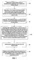
- FIG. 1illustrates a flow diagram of a method of manufacturing a complex structure from a two-dimensional layout, according to one exemplary embodiment of the present invention
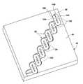
- FIG. 2illustrates a perspective diagram of a support plate having a recessed pattern formed therein that is capable of receiving a first series of flexible interconnects in a pre-determined arrangement
- FIG. 3-Aillustrates a perspective view of the support plate of FIG. 2 having a plurality of rigid members deposited in pre-determined arrangement over the flexible interconnects;
- FIG. 3-Billustrates a detailed view of a single rigid member shown in FIG. 3-A as deposited over a flexible interconnect;
- FIG. 4illustrates a perspective view of the support plate of FIG. 2 having a second series of flexible interconnects deposited over the rigid members in a pre-determined arrangement, whereupon curing, the assembly forms a plurality of stations;
- FIG. 5illustrates the resulting layered, two-dimensional assembly as being folded about itself and threaded onto a central spine, thus forming the three-dimensional complex structure
- FIG. 6illustrates the complex structure of FIG. 5 having a plurality of electrical taps in place to confirm the operation of any on-board systems existing on any of the stations;
- FIG. 7illustrates a block diagram of a segment of a complex structure, according to one exemplary embodiment, wherein the complex structure comprises a plurality of stations and a node, all electrically interconnected, all addressed, and multiplexed together, with the complex structure being operably coupled to a computer.
- the present inventiondescribes a method for manufacturing a three-dimensional, complex structure using a two-dimensional layout, wherein the complex structure comprises a plurality of performance stations that are preferably segmented, such as intelligence and/or actuation or electromechanical stations.
- the present invention methodaccomplishes all of the assembly of the complex structure, such as mechanical and electrical interconnects, in only a few steps, wherein the complex structure is then formed.
- the present inventionlends itself particularly well to mass fabrication of complex structures.
- the present invention methodmay be used to manufacture a variety of different types of complex structures.
- one generic type of complex structuremay comprise various electromechanical structures, such as robotic devices, medical devices, and others.
- the complex electromechanical structuremay comprise an electromechanical guidewire configured for use in various applications and in various industries, such as the medical or robotic industries, wherein the electromechanical guidewire comprises a plurality of performance stations having one or more on-board systems capable of performing various intelligent (e.g., data processing, signal receiving, signal transmitting, sensing, etc.), mechanical (e.g., actuation, locomotion), valving, or other functions.
- various intelligente.g., data processing, signal receiving, signal transmitting, sensing, etc.
- mechanicale.g., actuation, locomotion
- valvingor other functions.
- stationshall be understood to mean a rigid or semi-rigid member having at least one flexible interconnect connected thereto.
- a complex structure according to the present inventionwill typically comprise a plurality of stations, some of which may be support stations, performance stations, or both.
- performance stationshall be understood to mean a rigid member configured with or supporting thereon one or more on-board systems.
- Performance stationsmay include intelligent performance stations, electrical performance stations, mechanical performance stations, actuation performance stations, information gathering performance stations, valving and pumping performance stations, electromechanical performance stations, and others.
- On-board systemsmay include circuitry, circuit boards, actuators, valves, sensors, transmitters, cameras, locomotion devices or systems, or any combination of these. Those skilled in the art will recognize others.
- intelligentor “intelligence,” as used herein, shall be understood to describe those on-board features or components of the present invention having the capability to perform one or more data processing functions. This may include the capability to receive, process, send, and store electronic signals.
- Step 14comprises obtaining a support plate having a pre-determined, patterned recess formed in a surface thereof.
- Step 18comprises depositing a first series of individual flexible interconnects into the recess, the flexible interconnects being aligned parallel to one another in a common plane and supported by the support plate.
- Step 22comprises adhering, with adhering means, at least one rigid member to each of the flexible interconnects of the first series.
- Step 26comprises adhering, with adhering means, a second series of individual flexible interconnects to the rigid members to form a plurality of stations, wherein each of the second series of flexible interconnects is adhered to two rigid members of adjacent flexible interconnects of the first series, the flexible interconnects of the second series being formed perpendicular to the flexible interconnects of the first series.
- Step 30comprises curing the adhering means to form an assembled, layered structure.
- Step 34comprises removing the layered structure from the support plate and folding, systematically, the layered structure on itself and causing at least some of the stations to be supported about a central spine in a segmented manner.
- the flexible interconnects on either side of the rigid membersmay comprise a single strand of material rather than a plurality of individual pieces.
- FIGS. 2-6illustrate the steps recited above as applied to the manufacture of a specific exemplary type of complex structure. More specifically, FIGS. 1-6 illustrate the various components and elements involved in manufacturing a segmented complex structure in accordance with the steps recited above, wherein the complex structure is in the form of a guidewire having a plurality of performance stations configured with the ability to support a plurality of on-board systems capable or performing one or more mechanical, electrical, electro-mechanical, or other functions. With specific reference to FIG. 2 , illustrated is a support plate 40 having an upper surface 44 and a recessed portion 48 formed in the upper surface 44 .
- the support plate 40effectively functions as a template having a pattern 52 for laying out, in a two-dimensional manner, the various components used to make up the complex structure.
- the recessed portion 48conforms to or comprises the desired pattern 52 .
- the recessed portion 48 and pattern 52 formed in the support plate 40further functions to properly align each of the components as they are laid out by providing boundaries.
- the boundary 56 of the pattern 52comprises the edges of the recessed portion 48 .
- the boundarymay be provided by a build-up extending above the surface 44 of the support plate 40 , wherein the components of the complex structure are laid upon the surface 44 rather than within a recessed portion.
- the size and geometry of the particular pattern 52may vary depending upon the type or configuration of complex structure desired to be produced.
- the patterncomprises a step-like configuration, with a plurality of similarly sized rectangular shaped segments with rounded ends arranged in an overlapping manner one with another.
- other patternsmay be formed in the support plate 40 as will be recognized by those skilled in the art.
- the support plate 40may be used to form a continuous complex structure or various segments of a complex structure.
- the support plate 40is most likely used to form various segments of a complex guidewire structure due to its small size and the relatively small number of components able to be laid out about the support plate 40 , as shown.
- the support plate 40may comprise larger sizes capable of facilitating the formation of much larger complex structures or segments.
- the recessed portion 48may be configured to accommodate and support the layout of components of various sizes.
- the recessed portion 48may comprise any depth (or alternatively, any buildups may comprise any height) or varying depths (or alternatively varying buildup heights), depending upon the complex structure to be formed.
- the recess 48may not be required to be as deep to accommodate and support those components used to make up a simple guidewire structure having no on-board systems, as opposed to the depth that may be needed to accommodate and support a complex structure having one or more on-board components, such as a mechanical actuator or other system or device.
- the support plate 40may comprise any metal or non-metal material capable of supporting the various complex structure components in place during the manufacturing process. And, as indicated above, the support plate 40 may be configured to comprise any size and geometric configuration.
- a first series or set of individual flexible interconnects 70are laid out in a common plane within the recess 48 .
- the flexible interconnects 70are configured to be usable within a two-dimensional layout.
- Each flexible interconnect 70is further configured to provide the foundation for receiving all other components, which are also configured to be usable within a two-dimensional layout.
- the flexible interconnects 70function to operably interconnect one or more rigid members or stations of the complex guidewire structure.
- the interconnection between the rigid members or stationsmay provide multiple functions.
- the interconnectsmay be configured to provide mechanical support, or they may be configured to comprise an electrical interconnection element, depending upon the makeup or configuration of the material used, or both of these.
- the interconnects 70 between the rigid membersare intended to be flexible in order to facilitate the various movements and functions of the segments and stations during use of the guidewire structure.
- the interconnects 70are able to likewise move with the rigid members without sacrificing functionality. This is particularly advantageous when the flexible interconnects 70 operate to carry electrical current or signals.
- the present inventioncontemplates a variety of interconnect combinations being possible.
- Each of the flexible interconnects 70comprise a pre-determined two-dimensional size and shape depending upon the particular complex structure to be formed.
- the pattern 52 formed in the support plate 40comprises a corresponding size and shape to accommodate or receive the flexible interconnects 70 , in two-dimensional form.
- the flexible interconnects 70each comprise a two-dimensional size and shape that allows them to be properly supported within the pattern 52 of the support plate 40 during manufacturing.
- each of the flexible interconnects 70comprise a two-dimensional form with a first surface 74 , a second surface (not shown), a slot or slotted portion 82 , which purpose or function will be discussed in detail below, and a perimeter 86 .
- the flexible interconnects 70each comprise a rectangular shape with rounded ends, as this shape will allow them to take on the desired configuration in the three-dimensional complex structure when formed.
- the first series of flexible interconnects 70are all laid out so that they are oriented in the same direction and in a parallel manner with respect to one another.
- Each flexible interconnect 70is laterally offset from the other a pre-determined distance.
- Each interconnect 70is also offset from the other a pre-determined distance lengthwise (which distance is shown as substantially half the length of a flexible interconnect).
- the various interconnects 70are positioned in a step-like manner with respect to one another (as dictated by pattern 52 ).
- the recessed portion 48 formed in the pattern 52is configured to allow the flexible interconnects 70 to nest therein.
- the support plate 40may take on any configuration as long as it is capable of supporting the flexible interconnects 70 in a proper orientation.
- the flexible interconnects 70may comprise any suitable material capable of flexing, such as plastic, polymer, shape memory alloy and polyimide film.
- the flexible interconnects 70each comprise thin-layer strips of metalized polyimide material, which material is commonly known in the art.
- Each piece of metalized polyimide filmcomprises a plurality of electrical connectors 90 configured to electrically connect the metalized polyimimde film to adjacent segments or stations and to other components making up the complex guidewire structure, such as one or more electronic on-board components (e.g., data or signal processing system).
- the metalized polyimide filmfacilitates the carrying of electrical current or signals along the length of the complex structure from segment to segment or station to station, which electrical signals may be used for a variety of purposes, such as to power certain components of on-board systems located on the various segments or stations of the complex guidewire structure.
- the various rigid members or stations of the complex guidewire structure, or individual stationsmay be addressed and networked together.
- the complex guidewire structuremay be multiplexed, allowing any number of stations to communicate with one another and/or with various input and output devices, such as a computer. The concepts of addressing, networking, and multiplexing are discussed in greater detail below.
- the flexible interconnectsmay comprise a single strand of material, such as a single strand of metalized polyimide film, sized and shaped to fit within the pattern 52 in a similar manner as the individual flexible interconnect pieces.
- the sameis true for the flexible interconnects on the opposite side of the rigid members, as discussed below.
- the single strand flexible interconnectwill still comprise the necessary slots or apertures to accommodate a central spine, as well as any electrical connectors, conduits, etc. desired.
- the rigid members 102are comprised of circular discs having an first surface 106 , a second surface (not shown), an aperture 114 centrally formed therein, and a perimeter 118 defining a circle.
- adhering meansPrior to disposing the rigid members 102 over the flexible interconnects 70 , adhering means, such as an adhesive or solder paste, is applied to the areas where the rigid members 102 will be attached to the flexible interconnects 70 , or where electrical connectivity is required or desired.
- the adhering meansfunctions to operably attach the rigid members 102 to the flexible interconnects 70 , such as to electrically connect the rigid member with the electrical components of the flexible interconnect (e.g., the electrical connectors and/or electrical conduits in the polyimide material).
- a suitable adhering meansmay be used to electrically connect the electrical connectors in the flexible interconnect 70 (see electrical connectors 90 in FIG. 2 ) to the rigid members 102 , thus allowing the rigid members 102 to carry an electrical current through one or more electrical conduits supported thereon, and to electrically connect one or more on-board systems, if desired.
- the rigid members 102may comprise various types of materials, namely those selected from both metals and non-metals.
- the rigid members 102may be comprised of computer chips or silicon substrates with circuitry and data processing/storing components thereon, thus providing the ability for the rigid member to function as an intelligent performance station, such as a circuit board.
- the rigid members 102may be comprised of metal where additional support capabilities are needed. Indeed, various combinations of material are also contemplated.
- the rigid members 102are configured to function as support stations, and where appropriate, performance stations (e.g., intelligent, mechanical, etc.), that are independent of one another except through their interconnection via the flexible interconnects 70 .
- rigid member 102may comprise other shapes and sizes, depending upon the particular design of the complex structure being formed.
- the rigid members 102preferably comprise a diameter that is at least as long as the flexible interconnects 70 are wide.
- the rigid members 102may comprise a cross-section selected from the group consisting of a plane geometry shape and an arbitrary shape, as known in the art. However, this is not intended to be limiting as other sizes may be useful.
- the rigid members 102comprise a diameter that is the same or substantially the same length as the width of the flexible interconnects 70 .
- the radius of the rounded ends of the flexible interconnects 70are the same or substantially the same as the radius of the rigid members 102 , thus allowing a portion of their perimeters 86 and 118 , respectively, to match.
- the rigid members 102are positioned over the ends of the flexible interconnects 70 , one at each end, thus leaving a small gap between the two rigid members 102 on any given flexible interconnect, and thus leaving a portion of the slot 82 exposed, or not covered.
- adjacent rigid members 102 located on adjacent flexible interconnectsare also separated a given distance, for the purpose of leaving exposed a portion of the slot of the second series of flexible interconnects, as discussed below.
- the process of forming a complex structureinvolves disposing a second series of flexible interconnects over the first series and the rigid members, and aligning or positioning these in their proper place.
- a second series of flexible interconnects 132illustrated is a plurality of a second series of flexible interconnects 132 as overlaid upon the rigid members 102 .
- the second series of flexible interconnects 132are all laid out so that they are oriented in the same direction and in a parallel manner with respect to one another, but perpendicular or orthogonal to the first series of flexible interconnects 70 .
- Each flexible interconnect 132is laterally offset from the other a pre-determined distance.
- Each interconnect 132is also offset from the other a pre-determined distance lengthwise (which distance is shown as substantially half the length of a flexible interconnect).
- the various first and second series of flexible interconnects 70 and 132are positioned in a step-like manner with respect to one another (as dictated by pattern 52 ).
- the recessed portion 48 formed in the pattern 52is configured to support the second series of flexible interconnects 132 and to allow the second series of flexible interconnects 132 to nest therein as overlaid upon the rigid members 102 .
- the second series of flexible interconnects 132are similar to the first series in that they comprise a two-dimensional form with a first surface 136 , a second surface (not shown), a slot or slotted portion 144 , and a perimeter 148 .
- the flexible interconnects 132each comprise a rectangular shape with rounded ends, as this shape will allow them to take on the desired configuration in the three-dimensional complex structure when formed.
- the second series of flexible interconnects 132may also comprise electrical connectors 152 , similar to and that function as those disposed on the first series of flexible interconnects.
- the second series of flexible interconnects 132may comprise any size, shape, material, etc. as discussed above with respect to the first series of flexible interconnects.
- adhering meansPrior to laying out and aligning or positioning the second series of flexible interconnects 132 , adhering means, such as an adhesive or solder paste, is applied to the areas where the rigid members 102 will be attached to the flexible interconnects 132 , or where electrical connectivity is required or desired.
- the adhering meansfunctions to attach the rigid members 102 to the second series of flexible interconnects 132 in the same manner as discussed above. As such, the rigid members 102 , with their flexible interconnect counterparts, become defined stations to be disposed and situated in their proper place to make up the complex structure.
- various on-board systems or components or devicesmay be laid out and attached to one or more of the rigid members 102 .
- a particular rigid member or stationis to function as a performance station, such as an intelligent performance station in the form of a computer chip
- all of the necessary data processing, data storage, and circuitrymay be applied to the rigid member 102 at this time.
- Other on-board systemsmay include valving systems, micro cameras, actuators, deployment systems, etc.
- the on-board systemsmay enable the rigid members to function as mechanical or fluid or electro-mechanical performance stations.
- the rigid membersmay support actuators and valves operable with the actuators, which actuators and valves may be in fluid communication with a hydraulic bus running parallel to the central spine.
- the present inventioncontemplates any component, system or device functioning an on-board system and being incorporated into the layered, two-dimensional layout used to ultimately form the complex structure.
- the on-board systemsare operably coupled or connected to the rigid members and/or the flexible interconnects.
- these componentsare electrically connected to the electrical components in the flexible interconnects, such as the electrical connectors and conduits (e.g., those present on the polyimide film), and also any electrical components located on the rigid members required for operation of the data processing components.
- the data processing componentscan perform their intended function of receiving, transmitting, and/or storing electrical signals received.
- the flexible interconnectsprovide an uninterrupted conduit for electrical signals to be transmitted from any one station to any other station in the complex structure and from any input device (such as a computer) in communication with the complex structure to any station.
- the complex structuremay comprise one or more nodes existing between the stations.
- Exemplary nodesinclude actuating devices or systems, cameras, sensors, transmitters, etc.
- the adhering meansmay then be cured to complete the formation of the two-dimensional assembly.
- One exemplary curing processcomprises covering the layered two-dimensional structure with a top plate and exposing the same to a pre-determined temperature for a pre-determined duration of time. Other curing procedures used to cure the adhering means will be apparent to those skilled in the art.
- the two-dimensional assemblyis removed from the support plate and threaded along a central spine 160 by systematically folding the flexible interconnects 70 and 132 , and therefore the rigid members 102 , about one another.
- the central spine 160is inserted through the portion of the slots in each of the flexible interconnects 70 and 132 left exposed between each of the rigid members 132 , as well as the apertures formed in the rigid members 102 , as shown.
- the flexible interconnects 70 and 132are preferably folded to locate the flexible interconnects inside of or between each corresponding rigid member as supported about the central spine.
- each of the rigid members 102is situated about the central spine 160 , as stations, with the flexible interconnects spanning therebetween.
- the rigid members 102may be attached or fixed to the central spine 160 at their appropriate locations using any known attachment means.
- the central spine 160may comprise any type of support member, such as a compression member, capable of supporting the rigid members 102 in place.
- the central spine 160will also be capable of providing the complex structure with torquability, pushability, and flexing characteristics.
- the resulting structurecomprises a three-dimensional complex structure 10 formed from the above-described two-dimensional layout.
- Each of the rigid members 102function as or provide a station capable of performing one or more tasks.
- a stationmay be a simple support station contributing to the overall support of the complex structure, or a station may function as a performance station, wherein one or more on-board systems is configured to perform an intelligent (e.g., data processing, signal receiving, signal transmitting, sensing, etc.) function, a mechanical function (e.g., actuation, locomotion), a valving function, or some other function as recognized by those skilled in the art.
- the stations of the complex structureare capable of supporting one or more operable on-board systems, as well as being able to receive and send signals, information, or other items to any other station in the complex structure, to a node, or to a computer via the flexible interconnect and resulting electrical interconnection between the stations.
- the complex structureis also capable of unique movements. Indeed, the complex structure may be configured to bend, torque, twist, extend, etc. to perform its intended function.
- One exemplary complex structure that may be formed using the present invention methodmay be similar to, in both form and function, a complex guidewire.
- Another exemplary type of complex structuremay comprise a serpentine robot.
- a formed three-dimensional complex structure 10with a plurality of electrical taps 170 situated about the central spine 160 and disposed between various stations on the complex structure 10 .
- the electrical taps 170may be used to confirm proper operation of any on-board systems existing on the various stations, and may then be broken off upon confirmation.
- FIG. 7illustrates a graphical rendition of a three-dimensional complex structure formed from a two-dimensional layout, according to one exemplary embodiment of the present invention. Specifically, FIG. 7 illustrates the various interconnections between the several stations.
- the complex structure 210comprises a plurality of stations, namely stations 212 - a , 212 - b , 212 - c , 212 - d , and 212 - e .
- Each of these stations 212are electrically interconnected to one another, and any nodes existing in the complex structure, such as node 222 , via the electrical connection 226 .
- any one station 212may communicate with any other station or any other node in the complex structure.
- FIG. 7illustrates performance stations 220 - b and 220 - d .
- the electrical connection 226 shownis carried along the flexible interconnects (not shown) described above. This type of interconnection provides significant advantages over prior related interconnections as will be recognized by those skilled in the art.
- each of these stations, and any nodesmay comprise an identifier or address S x (or N x in the case of a node), thus providing the complex 210 structure with a network of stations 212 and nodes 222 .
- the complex structureis further capable of being multiplexed together.
- the flexible interconnectsprovide the ability to significantly reduce the number of electrical wires running between the various stations and a computer or other input source.
- the complex structure 210is electrically connected to computer 250 via connection 230 .
- the term “preferably”is non-exclusive where it is intended to mean “preferably, but not limited to.” Any steps recited in any method or process claims may be executed in any order and are not limited to the order presented in the claims. Means-plus-function or step-plus-function limitations will only be employed where for a specific claim limitation all of the following conditions are present in that limitation: a) “means for” or “step for” is expressly recited; and b) a corresponding function is expressly recited. The structure, material or acts that support the means-plus function are expressly recited in the description herein. Accordingly, the scope of the invention should be determined solely by the appended claims and their legal equivalents, rather than by the descriptions and examples given above.
Landscapes
- Health & Medical Sciences (AREA)
- Life Sciences & Earth Sciences (AREA)
- Biophysics (AREA)
- Pulmonology (AREA)
- Engineering & Computer Science (AREA)
- Anesthesiology (AREA)
- Biomedical Technology (AREA)
- Heart & Thoracic Surgery (AREA)
- Hematology (AREA)
- Animal Behavior & Ethology (AREA)
- General Health & Medical Sciences (AREA)
- Public Health (AREA)
- Veterinary Medicine (AREA)
- Structure Of Printed Boards (AREA)
Abstract
Description
Claims (24)
Priority Applications (2)
| Application Number | Priority Date | Filing Date | Title |
|---|---|---|---|
| US12/151,730US8002716B2 (en) | 2007-05-07 | 2008-05-07 | Method for manufacturing a complex structure |
| US13/181,380US8434208B2 (en) | 2007-05-07 | 2011-07-12 | Two-dimensional layout for use in a complex structure |
Applications Claiming Priority (2)
| Application Number | Priority Date | Filing Date | Title |
|---|---|---|---|
| US92814907P | 2007-05-07 | 2007-05-07 | |
| US12/151,730US8002716B2 (en) | 2007-05-07 | 2008-05-07 | Method for manufacturing a complex structure |
Related Child Applications (1)
| Application Number | Title | Priority Date | Filing Date |
|---|---|---|---|
| US13/181,380DivisionUS8434208B2 (en) | 2007-05-07 | 2011-07-12 | Two-dimensional layout for use in a complex structure |
Publications (2)
| Publication Number | Publication Date |
|---|---|
| US20080281231A1 US20080281231A1 (en) | 2008-11-13 |
| US8002716B2true US8002716B2 (en) | 2011-08-23 |
Family
ID=39724678
Family Applications (2)
| Application Number | Title | Priority Date | Filing Date |
|---|---|---|---|
| US12/151,730Expired - Fee RelatedUS8002716B2 (en) | 2007-05-07 | 2008-05-07 | Method for manufacturing a complex structure |
| US13/181,380Expired - Fee RelatedUS8434208B2 (en) | 2007-05-07 | 2011-07-12 | Two-dimensional layout for use in a complex structure |
Family Applications After (1)
| Application Number | Title | Priority Date | Filing Date |
|---|---|---|---|
| US13/181,380Expired - Fee RelatedUS8434208B2 (en) | 2007-05-07 | 2011-07-12 | Two-dimensional layout for use in a complex structure |
Country Status (4)
| Country | Link |
|---|---|
| US (2) | US8002716B2 (en) |
| EP (1) | EP2144659A1 (en) |
| JP (1) | JP2010526590A (en) |
| WO (1) | WO2008137953A1 (en) |
Cited By (17)
| Publication number | Priority date | Publication date | Assignee | Title |
|---|---|---|---|---|
| US20110268914A1 (en)* | 2007-05-07 | 2011-11-03 | Jacobsen Stephen C | Two-Dimensional Layout For Use In A Complex Structure |
| US20130231778A1 (en)* | 2010-11-16 | 2013-09-05 | Universal Robots Aps | Method and Means for Controlling a Robot |
| US20130298549A1 (en)* | 2012-04-04 | 2013-11-14 | Samuel Michael Manriquez, JR. | Actuator and Method |
| US8935014B2 (en) | 2009-06-11 | 2015-01-13 | Sarcos, Lc | Method and system for deploying a surveillance network |
| US9031698B2 (en) | 2012-10-31 | 2015-05-12 | Sarcos Lc | Serpentine robotic crawler |
| US9409292B2 (en) | 2013-09-13 | 2016-08-09 | Sarcos Lc | Serpentine robotic crawler for performing dexterous operations |
| US9566711B2 (en) | 2014-03-04 | 2017-02-14 | Sarcos Lc | Coordinated robotic control |
| US9833897B2 (en) | 2011-09-28 | 2017-12-05 | Universal Robots A/S | Calibration and programming of robots |
| US10195746B2 (en) | 2014-09-26 | 2019-02-05 | Teradyne, Inc. | Grasping gripper |
| US10399232B2 (en) | 2014-03-04 | 2019-09-03 | Universal Robots A/S | Safety system for industrial robot |
| US10850393B2 (en) | 2015-07-08 | 2020-12-01 | Universal Robots A/S | Method for extending end user programming of an industrial robot with third party contributions |
| US11474510B2 (en) | 2016-04-12 | 2022-10-18 | Universal Robots A/S | Programming a robot by demonstration |
| US12296485B2 (en) | 2019-10-22 | 2025-05-13 | Universal Robots A/S | Robot arm with adaptive three-dimensional boundary in free-drive |
| US12311550B2 (en) | 2020-12-31 | 2025-05-27 | Sarcos Corp. | Smart control system for a robotic device |
| USD1082878S1 (en) | 2022-01-14 | 2025-07-08 | Universal Robots A/S | Robot joint |
| US12384019B2 (en) | 2019-10-22 | 2025-08-12 | Universal Robots A/S | Safe activation of free-drive mode of robot arm |
| US12397414B2 (en) | 2019-10-22 | 2025-08-26 | Universal Robots A/S | Maintaining free-drive mode of robot arm for period of time |
Families Citing this family (8)
| Publication number | Priority date | Publication date | Assignee | Title |
|---|---|---|---|---|
| ATE473907T1 (en) | 2006-11-13 | 2010-07-15 | Raytheon Sarcos Llc | VERSATILE ENDLESS BELT FOR LIGHTWEIGHT MOBILE ROBOTS |
| WO2010126669A2 (en)* | 2009-03-25 | 2010-11-04 | Massachusetts Institute Of Technology | Cellular automotion digital material |
| US9137517B2 (en)* | 2012-10-05 | 2015-09-15 | Blackberry Limited | Methods and devices for generating a stereoscopic image |
| US10983506B2 (en) | 2013-10-16 | 2021-04-20 | Proto Labs, Inc. | Methods and software for manufacturing a discrete object from an additively manufactured body of material including a precursor to a discrete object and a reference feature(s) |
| US10071303B2 (en) | 2015-08-26 | 2018-09-11 | Malibu Innovations, LLC | Mobilized cooler device with fork hanger assembly |
| US10807659B2 (en) | 2016-05-27 | 2020-10-20 | Joseph L. Pikulski | Motorized platforms |
| US11249457B2 (en) | 2017-03-31 | 2022-02-15 | Proto Labs Inc | Methods and systems for manufacturing a support structure |
| US10656626B2 (en) | 2017-06-01 | 2020-05-19 | Proto Labs, Inc. | Methods and software for manufacturing a discrete object from an additively manufactured body of material including a precursor to a discrete object and a reference feature(s) |
Citations (277)
| Publication number | Priority date | Publication date | Assignee | Title |
|---|---|---|---|---|
| US1107874A (en) | 1911-11-06 | 1914-08-18 | Bullock Tractor Company | Vehicle. |
| US1112460A (en) | 1913-04-21 | 1914-10-06 | Harry W Leavitt | Tractor. |
| US1515756A (en) | 1922-05-12 | 1924-11-18 | Roy Irene | Articulated coupling device for heavy loads |
| US1975726A (en) | 1931-09-15 | 1934-10-02 | Martinage Leon | Endless track vehicle |
| US2025999A (en) | 1932-01-25 | 1935-12-31 | Edward C Myers | Rubber covered flexible track |
| US2082920A (en) | 1935-12-24 | 1937-06-08 | Aulmont W Tye | Trailer |
| US2129557A (en) | 1937-06-09 | 1938-09-06 | Charles H Beach | Detachable traction lug |
| US2311475A (en) | 1941-09-19 | 1943-02-16 | Theodore G Schmeiser | Auxiliary traction wheel |
| US2312072A (en) | 1940-03-07 | 1943-02-23 | Tenger Victoria | Endless track for vehicles |
| US2329582A (en) | 1942-11-02 | 1943-09-14 | Harold M Bishop | Tread |
| US2345763A (en) | 1941-02-27 | 1944-04-04 | Goodrich Co B F | Flexible track for self-laying track vehicles |
| US2701169A (en) | 1954-08-18 | 1955-02-01 | Edgar M Cannon | Mud lug for endless traction track links |
| US2850147A (en) | 1954-08-20 | 1958-09-02 | James M Hill | Mobile curvable conveyor |
| US2933143A (en) | 1957-06-25 | 1960-04-19 | Canadair Ltd | Articulated vehicle |
| US2967737A (en) | 1959-11-30 | 1961-01-10 | George V Moore | Detachable traction units |
| US3037571A (en) | 1959-08-17 | 1962-06-05 | Schield Bantam Company | Wide base crawler |
| US3060972A (en) | 1957-08-22 | 1962-10-30 | Bausch & Lomb | Flexible tube structures |
| US3166138A (en) | 1961-10-26 | 1965-01-19 | Jr Edward D Dunn | Stair climbing conveyance |
| US3190286A (en) | 1961-10-31 | 1965-06-22 | Bausch & Lomb | Flexible viewing probe for endoscopic use |
| US3215219A (en) | 1963-07-22 | 1965-11-02 | Lockheed Aircraft Corp | Articulated vehicle |
| US3223462A (en) | 1963-04-25 | 1965-12-14 | Boeing Co | Endless track for a track laying vehicle |
| US3266059A (en) | 1963-06-19 | 1966-08-16 | North American Aviation Inc | Prestressed flexible joint for mechanical arms and the like |
| US3284964A (en) | 1964-03-26 | 1966-11-15 | Saito Norio | Flexible beam structures |
| US3311424A (en) | 1965-06-03 | 1967-03-28 | Marval & O Farrell | Tractive device comprising a belt driven soft roller |
| US3362492A (en) | 1966-02-14 | 1968-01-09 | Darrell L. Hansen | Snowbike attachment |
| US3387896A (en) | 1965-02-11 | 1968-06-11 | Erlau Ag Eisen Drahtwerk | Antiskid and tire protective chain |
| US3489236A (en) | 1968-08-01 | 1970-01-13 | Us Army | Egressing device for military vehicles |
| US3497083A (en) | 1968-05-10 | 1970-02-24 | Us Navy | Tensor arm manipulator |
| GB1199729A (en) | 1966-10-24 | 1970-07-22 | Rowland Lewis Robert Morgan | Tractor Vehicle for Underwater Use |
| US3565198A (en) | 1967-06-26 | 1971-02-23 | Whiting Corp | Steering, driving and single track support systems for vehicles |
| US3572325A (en) | 1968-10-25 | 1971-03-23 | Us Health Education & Welfare | Flexible endoscope having fluid conduits and control |
| US3609804A (en) | 1969-08-27 | 1971-10-05 | Marvin Glass & Associates | Vehicle |
| US3650343A (en) | 1970-03-12 | 1972-03-21 | John B Helsell | Ski slope traversing and conditioning vehicle |
| US3700115A (en) | 1970-09-17 | 1972-10-24 | Koehring Co | Vehicle with variable width ground supports |
| US3707218A (en) | 1970-10-26 | 1972-12-26 | Mackey M Payne | Conveyor apparatus |
| US3712481A (en) | 1971-12-23 | 1973-01-23 | Mc Donnell Douglas Corp | Actuator |
| US3715146A (en) | 1970-01-19 | 1973-02-06 | W Robertson | Snow cleat and track for tracked vehicle |
| US3757635A (en) | 1971-03-23 | 1973-09-11 | F Hickerson | Multi-purpose munitions carrier |
| US3808078A (en) | 1970-01-05 | 1974-04-30 | Norfin | Glass fiber cable, method of making, and its use in the manufacture of track vehicles |
| US3820616A (en) | 1972-02-03 | 1974-06-28 | American Hoist & Derrick Co | Crawler vehicle with dual extensible side frames |
| US3841424A (en) | 1971-12-27 | 1974-10-15 | Caterpillar Tractor Co | Triangular track resilient bogie suspension |
| US3864983A (en) | 1972-09-15 | 1975-02-11 | Stephen C Jacobsen | Rotary-to-linear and linear-to-rotary motion converters |
| US3933214A (en) | 1972-07-12 | 1976-01-20 | Guibord Georges E | All terrain pleasure vehicle |
| US3934664A (en) | 1973-02-01 | 1976-01-27 | Pohjola Jorma | Steering mechanism for track vehicles |
| US3974907A (en) | 1971-10-29 | 1976-08-17 | Gordon A. Brewer | Flexible mobile conveyor |
| US4051914A (en) | 1975-01-30 | 1977-10-04 | Pohjola Jorma | Endless track vehicle having a steerable end and method for operating the same |
| US4059315A (en) | 1976-01-02 | 1977-11-22 | Jolliffe James D | Cleat anchor for flexible vehicle track |
| US4068905A (en) | 1975-09-10 | 1978-01-17 | Black Chester A | Detachable road protecting device for tracked vehicles |
| US4107948A (en) | 1976-01-30 | 1978-08-22 | Trallfa Nils Underhaug A/S | Flexible robot arm |
| US4109971A (en) | 1976-10-12 | 1978-08-29 | Black Chester A | Detachable road protecting devices for tracked vehicles |
| US4132279A (en) | 1976-08-18 | 1979-01-02 | Lende Leendert J V D | Automotive tractor unit, more particularly for riding and working on vertical walls, ceilings and suchlike |
| US4218101A (en) | 1978-04-03 | 1980-08-19 | De Lorean Manufacturing Company | Low disturbance track cleat and ice calk structure for firm or icy snow |
| US4260053A (en) | 1979-10-09 | 1981-04-07 | Hirosuke Onodera | Flexible conveyor belt |
| US4332317A (en) | 1979-07-03 | 1982-06-01 | Kloeckner-Werke Ag | Scraper chain conveyor |
| US4332424A (en) | 1978-04-03 | 1982-06-01 | De Lorean Manufacturing Company | Low disturbance track cleat and ice calk structure for firm or icy snow |
| US4339031A (en) | 1979-10-01 | 1982-07-13 | Joy Manufacturing Company | Monorail suspended conveyor system |
| US4393728A (en) | 1979-03-16 | 1983-07-19 | Robotgruppen Hb | Flexible arm, particularly a robot arm |
| US4396233A (en) | 1980-01-29 | 1983-08-02 | Her Majesty The Queen In Right Of Canada As Represented By The Minister Of National Defence | Track for rope vehicle |
| DE3025840C2 (en) | 1980-07-08 | 1983-08-04 | Mowag Motorwagenfabrik Ag, Kreuzlingen | Chain link for a crawler belt |
| US4453611A (en) | 1980-10-10 | 1984-06-12 | Stacy Jr Jack C | Terrain vehicle having a single, latterally bendable track |
| US4483407A (en) | 1982-03-26 | 1984-11-20 | Hitachi, Ltd. | Variable configuration track laying vehicle |
| US4489826A (en) | 1982-02-05 | 1984-12-25 | Philip Dubson | Adjustable apparatus |
| US4494417A (en) | 1979-03-16 | 1985-01-22 | Robotgruppen Hb | Flexible arm, particularly a robot arm |
| US4551061A (en) | 1983-04-18 | 1985-11-05 | Olenick Ralph W | Flexible, extensible robot arm |
| US4589460A (en) | 1978-01-03 | 1986-05-20 | Albee William H | Off road vehicles |
| US4621965A (en) | 1983-02-10 | 1986-11-11 | United Kingdom Atomic Energy Authority | Manipulators |
| US4636137A (en) | 1980-10-24 | 1987-01-13 | Lemelson Jerome H | Tool and material manipulation apparatus and method |
| US4646906A (en) | 1984-09-06 | 1987-03-03 | Fairchild Incorporated | Apparatus for continuously conveying coal from a continuous miner to a remote floor conveyor |
| US4661039A (en) | 1983-10-20 | 1987-04-28 | Donaldson Company | Flexible-frame robot |
| EP0105418B1 (en) | 1982-10-06 | 1987-06-03 | Rainer Hitzel | Tube manipulator for traversing conduits |
| US4700693A (en) | 1985-12-09 | 1987-10-20 | Welch Allyn, Inc. | Endoscope steering section |
| US4706506A (en) | 1985-10-25 | 1987-11-17 | Commissariat A L'energie Atomique | Pickup for measuring forces and torques and application of such a pickup to a follower and a gripper |
| US4712969A (en) | 1983-08-29 | 1987-12-15 | Kabushiki Kaisha Toshiba | Expandable and contractable arms |
| US4714125A (en) | 1986-05-05 | 1987-12-22 | Stacy Jr Jack C | Single laterally bendable track snowmobile |
| US4727949A (en) | 1984-03-05 | 1988-03-01 | Watercraft Offshore Canada Ltd. | All terrain vehicle and method of operating same |
| US4736826A (en) | 1985-04-22 | 1988-04-12 | Remote Technology Corporation | Remotely controlled and/or powered mobile robot with cable management arrangement |
| US4752105A (en) | 1985-10-24 | 1988-06-21 | Barnard Jan H | Vehicle traction |
| US4756662A (en) | 1986-03-31 | 1988-07-12 | Agency Of Industrial Science & Technology | Varible compliance manipulator |
| US4765795A (en) | 1986-06-10 | 1988-08-23 | Lord Corporation | Object manipulator |
| US4784042A (en) | 1986-02-12 | 1988-11-15 | Nathaniel A. Hardin | Method and system employing strings of opposed gaseous-fluid inflatable tension actuators in jointed arms, legs, beams and columns for controlling their movements |
| US4796607A (en) | 1987-07-28 | 1989-01-10 | Welch Allyn, Inc. | Endoscope steering section |
| US4806066A (en) | 1982-11-01 | 1989-02-21 | Microbot, Inc. | Robotic arm |
| US4815911A (en) | 1982-07-05 | 1989-03-28 | Komatsu, Ltd. | Device for torsion-proof connection of an element in a robot arm or the like |
| US4815319A (en) | 1987-01-05 | 1989-03-28 | Protee Groupement D'interet Economique | System for determining the movement of a track vehicle |
| US4828339A (en) | 1986-09-30 | 1989-05-09 | Joy Technologies Inc. | Crawler chain |
| US4848179A (en) | 1988-02-16 | 1989-07-18 | Trw Inc. | Flexidigit robotic manipulator |
| US4862808A (en) | 1988-08-29 | 1989-09-05 | Gas Research Institute | Robotic pipe crawling device |
| US4878451A (en) | 1987-04-15 | 1989-11-07 | Siren Andy O | All-terrain amphibian vehicle |
| US4900218A (en) | 1983-04-07 | 1990-02-13 | Sutherland Ivan E | Robot arm structure |
| US4909341A (en) | 1985-10-29 | 1990-03-20 | The Secretary Of State For Defence In Her Britannic Majesty's Government Of The United Kingdom Of Great Britain And Northern Ireland | Unmanned articulated vehicle |
| US4924153A (en) | 1986-05-21 | 1990-05-08 | Kabushiki Kaisha Komatsu Seisakusho | Apparatus for guiding movement of an unmanned moving body |
| US4932491A (en) | 1989-03-21 | 1990-06-12 | The United States Of America As Represented By The Administrator Of The National Aeronautics And Space Administration | Body steered rover |
| US4932831A (en) | 1988-09-26 | 1990-06-12 | Remotec, Inc. | All terrain mobile robot |
| US4936639A (en) | 1986-12-18 | 1990-06-26 | Reta-Myynti Ky | Apparatus in a turning-track track-laying vehicle |
| US4977790A (en) | 1987-03-23 | 1990-12-18 | Kabushiki Kaisha Komatsu Seisakusho | Flexible arm |
| FR2638813B1 (en) | 1988-11-09 | 1991-02-01 | Nancy Ecole Sup Sciences Techn | SELF-PROPELLED VEHICLE FOR GRINDING OF PIPING |
| DE3626238C2 (en) | 1986-08-02 | 1991-04-04 | Hans Dipl.-Ing. 4690 Herne De Lachner | |
| US5018591A (en) | 1990-04-24 | 1991-05-28 | Caterpillar Inc. | Track laying work vehicle |
| US5021798A (en) | 1988-02-16 | 1991-06-04 | Trw Inc. | Antenna with positionable reflector |
| US5046914A (en) | 1988-07-12 | 1991-09-10 | Cybermation, Inc. | Parallel lifting device |
| US5080000A (en) | 1990-05-11 | 1992-01-14 | Bubic Frank R | Flexible robotic links and manipulator trunks made thereform |
| US5130631A (en) | 1989-03-06 | 1992-07-14 | Hewlett-Packard Company | Robot bus architecture with distributed electronics |
| US5142932A (en) | 1991-09-04 | 1992-09-01 | The United States Of America As Represented By The Administrator Of The National Aeronautics And Space Administration | Flexible robotic arm |
| US5174405A (en) | 1989-08-31 | 1992-12-29 | Framatone | Self-traveling robotic vehicle with inclinable propulsion units |
| US5174168A (en) | 1987-09-09 | 1992-12-29 | Kabushiki Kaisha Komatsu Seisakusho | Flexible robot arm |
| US5186526A (en) | 1990-08-31 | 1993-02-16 | General Chemical Corporation | One-piece crawler pad |
| US5199771A (en) | 1992-03-02 | 1993-04-06 | Logan Manufacturing Company | Not retaining cleat for vehicle endless track |
| US5205612A (en) | 1990-05-17 | 1993-04-27 | Z C Mines Pty. Ltd. | Transport apparatus and method of forming same |
| US5214858A (en) | 1990-07-12 | 1993-06-01 | Pepper Stuart E | Teach and repeat probe for a robot arm |
| US5219264A (en) | 1986-09-19 | 1993-06-15 | Texas Instruments Incorporated | Mobile robot on-board vision system |
| US5252870A (en) | 1991-03-01 | 1993-10-12 | Jacobsen Stephen C | Magnetic eccentric motion motor |
| US5297443A (en) | 1992-07-07 | 1994-03-29 | Wentz John D | Flexible positioning appendage |
| US5317952A (en) | 1991-11-22 | 1994-06-07 | Kinetic Sciences Inc. | Tentacle-like manipulators with adjustable tension lines |
| US5337732A (en) | 1992-09-16 | 1994-08-16 | Cedars-Sinai Medical Center | Robotic endoscopy |
| US5350033A (en) | 1993-04-26 | 1994-09-27 | Kraft Brett W | Robotic inspection vehicle |
| US5354124A (en) | 1993-09-07 | 1994-10-11 | Lmc Operating Corp. | Water sealed, cable reinforced vehicle endless track and cleat assembly |
| US5363935A (en) | 1993-05-14 | 1994-11-15 | Carnegie Mellon University | Reconfigurable mobile vehicle with magnetic tracks |
| US5386741A (en) | 1993-06-07 | 1995-02-07 | Rennex; Brian G. | Robotic snake |
| US5413454A (en) | 1993-07-09 | 1995-05-09 | Movsesian; Peter | Mobile robotic arm |
| US5428713A (en) | 1991-11-25 | 1995-06-27 | Kabushiki Kaisha Toshiba | Compound module type manipulator apparatus |
| US5435405A (en) | 1993-05-14 | 1995-07-25 | Carnegie Mellon University | Reconfigurable mobile vehicle with magnetic tracks |
| US5440916A (en) | 1993-11-15 | 1995-08-15 | The United States Of America As Represented By The Administrator Of The National Aeronatics And Space Administration | Emergency response mobile robot for operations in combustible atmospheres |
| US5443354A (en) | 1992-07-20 | 1995-08-22 | The United States Of America As Represented By The Administrator Of The National Aeronautics And Space Administration | Hazardous materials emergency response mobile robot |
| US5451135A (en) | 1993-04-02 | 1995-09-19 | Carnegie Mellon University | Collapsible mobile vehicle |
| US5465525A (en) | 1993-12-29 | 1995-11-14 | Tomokiyo White Ant Co. Ltd. | Intellectual working robot of self controlling and running |
| US5466056A (en) | 1993-07-26 | 1995-11-14 | Lmc Operating Corp. | Cleat retaining assembly for vehicle endless track |
| US5469756A (en) | 1991-10-10 | 1995-11-28 | Siemens Aktiengesellschaft | Flexible robot arm |
| US5516249A (en) | 1994-05-10 | 1996-05-14 | Technical Research Associates, Inc. | Exoskeleton with kinesthetic feedback and robotic control |
| US5551545A (en) | 1994-03-18 | 1996-09-03 | Gelfman; Stanley | Automatic deployment and retrieval tethering system |
| US5556370A (en) | 1993-07-28 | 1996-09-17 | The Board Of Trustees Of The Leland Stanford Junior University | Electrically activated multi-jointed manipulator |
| US5562843A (en) | 1991-12-28 | 1996-10-08 | Joven Electric Co., Ltd. | Industrial robot with contact sensor |
| US5570992A (en) | 1954-07-28 | 1996-11-05 | Lemelson; Jerome H. | Free-traveling manipulator with optical feedback control and methods |
| US5573316A (en) | 1995-06-02 | 1996-11-12 | Wankowski; Russell A. | Lightweight snowmobile traction stud |
| US5588688A (en) | 1990-08-06 | 1996-12-31 | Sarcos, Inc. | Robotic grasping apparatus |
| US5672044A (en) | 1974-01-24 | 1997-09-30 | Lemelson; Jerome H. | Free-traveling manipulator with powered tools |
| DE19617852A1 (en) | 1996-04-23 | 1997-10-30 | Karlsruhe Forschzent | Process for the planar production of pneumatic and fluidic miniature manipulators |
| DE19714464A1 (en) | 1996-04-12 | 1997-10-30 | Ka Te System Ag | Control equipment for redevelopment of pipes |
| US5697285A (en) | 1995-12-21 | 1997-12-16 | Nappi; Bruce | Actuators for simulating muscle activity in robotics |
| EP0818283A1 (en) | 1996-07-08 | 1998-01-14 | Sony Corporation | Robot apparatus |
| US5712961A (en) | 1995-09-19 | 1998-01-27 | Minolta Co., Ltd. | Contact-type sensor |
| US5749828A (en) | 1995-12-22 | 1998-05-12 | Hewlett-Packard Company | Bending neck for use with invasive medical devices |
| US5770913A (en) | 1995-10-23 | 1998-06-23 | Omnific International, Ltd. | Actuators, motors and wheelless autonomous robots using vibratory transducer drivers |
| US5816769A (en) | 1995-11-07 | 1998-10-06 | Siemens Aktiengesellschaft | Flexible manipulator |
| US5821666A (en) | 1995-09-22 | 1998-10-13 | Nippondenso Co., Ltd. | United control system comprising a plurality of control units independently controllable |
| US5842381A (en) | 1994-07-28 | 1998-12-01 | Siemens Aktiengesellschaft | Precisely controllable flexible actuator |
| USRE36025E (en) | 1992-07-15 | 1999-01-05 | Kabushiki Kaisha Suzuki Shoki | Crawler pad |
| US5878783A (en) | 1995-05-22 | 1999-03-09 | British Gas Plc | Pipeline vehicle |
| US5888235A (en) | 1997-01-07 | 1999-03-30 | Sarcos, Inc. | Body-powered prosthetic arm |
| US5902254A (en) | 1996-07-29 | 1999-05-11 | The Nemours Foundation | Cathether guidewire |
| US5906591A (en) | 1996-10-22 | 1999-05-25 | Scuola Superiore Di Studi Universitari E Di Perfezionamento S. Anna | Endoscopic robot |
| US5984032A (en) | 1998-06-10 | 1999-11-16 | Gremillion; Ernest J. | Articulating marsh buggy |
| US6016385A (en) | 1997-08-11 | 2000-01-18 | Fanu America Corp | Real time remotely controlled robot |
| US6030057A (en) | 1996-06-19 | 2000-02-29 | Fikse; Tyman H. | Tractor endless tread |
| US6056237A (en) | 1997-06-25 | 2000-05-02 | Woodland; Richard L. K. | Sonotube compatible unmanned aerial vehicle and system |
| US6109705A (en) | 1998-08-07 | 2000-08-29 | Camoplast, Inc. | Snowmobile drive track for traveling on icy and hardened snow surface |
| US6113343A (en) | 1996-12-16 | 2000-09-05 | Goldenberg; Andrew | Explosives disposal robot |
| US6132133A (en) | 1996-06-12 | 2000-10-17 | Komatsu Ltd. | Crawler type vibratory compacting machine |
| US6138604A (en) | 1998-05-26 | 2000-10-31 | The Charles Stark Draper Laboratories, Inc. | Pelagic free swinging aquatic vehicle |
| US6162171A (en) | 1998-12-07 | 2000-12-19 | Wan Sing Ng | Robotic endoscope and an autonomous pipe robot for performing endoscopic procedures |
| DE10018075A1 (en) | 1999-06-29 | 2001-01-18 | Daimler Chrysler Ag | Combating explosive bodies, especially mines, involves using platform holding several devices with hollow charges forming projectiles deployed using three-dimensional optical sensor |
| US6186604B1 (en) | 1996-06-19 | 2001-02-13 | Tyman H. Fikse | Tractor endless tread |
| US6203126B1 (en) | 1998-06-05 | 2001-03-20 | Northern Freight Brokers, Inc. | Traction stud for a snowmobile belt made of a non-metal material |
| US6260501B1 (en) | 2000-03-17 | 2001-07-17 | Arthur Patrick Agnew | Submersible apparatus for transporting compressed gas |
| US6263989B1 (en) | 1998-03-27 | 2001-07-24 | Irobot Corporation | Robotic platform |
| US6264293B1 (en) | 1999-06-04 | 2001-07-24 | International Engineering & Manufacturing Inc | Traction stud mount and method of manufacturing and mounting |
| US6264294B1 (en) | 1999-06-04 | 2001-07-24 | International Engineering And Manufacturing, Inc. | Tapered traction stud, stud mount and method of making and mounting |
| US6281489B1 (en) | 1997-05-02 | 2001-08-28 | Baker Hughes Incorporated | Monitoring of downhole parameters and tools utilizing fiber optics |
| US20010037163A1 (en) | 2000-05-01 | 2001-11-01 | Irobot Corporation | Method and system for remote control of mobile robot |
| US6325749B1 (en) | 1996-10-18 | 2001-12-04 | Kabushiki Kaisha Yaskawa Denki | Robot vehicle for hot-line job |
| US6333631B1 (en) | 1999-03-08 | 2001-12-25 | Minister Of National Defence Of Her Majesty's Canadian Government | Cantilevered manipulator for autonomous non-contact scanning of natural surfaces for the deployment of landmine detectors |
| US6339993B1 (en) | 1997-10-22 | 2002-01-22 | Pii Pipetronix Gmbh | Device for passing through pipes |
| US6380889B1 (en) | 1999-02-19 | 2002-04-30 | Rheinmetall W & M Gmbh | Reconnaissance sonde |
| US6394204B1 (en) | 1998-12-15 | 2002-05-28 | Macmoter S.P.A. | Crawler or tracked vehicle having pivotable tracks |
| US6405798B1 (en) | 1996-07-13 | 2002-06-18 | Schlumberger Technology Corporation | Downhole tool and method |
| US6408224B1 (en) | 1999-11-10 | 2002-06-18 | National Aerospace Laboratory Of Science Technology Agency | Rotary articulated robot and method of control thereof |
| US6411055B1 (en) | 1997-11-30 | 2002-06-25 | Sony Corporation | Robot system |
| US6422509B1 (en) | 2000-11-28 | 2002-07-23 | Xerox Corporation | Tracking device |
| US6430475B2 (en) | 2000-04-10 | 2002-08-06 | National Aerospace Laboratory Of Japan | Pressure-distribution sensor for controlling multi-jointed nursing robot |
| US20020128714A1 (en) | 1999-06-04 | 2002-09-12 | Mark Manasas | Orthopedic implant and method of making metal articles |
| US6450104B1 (en) | 2000-04-28 | 2002-09-17 | North Carolina State University | Modular observation crawler and sensing instrument and method for operating same |
| US20020140392A1 (en) | 2001-03-30 | 2002-10-03 | Johann Borenstein | Apparatus for obstacle traversion |
| US6484083B1 (en) | 1999-06-07 | 2002-11-19 | Sandia Corporation | Tandem robot control system and method for controlling mobile robots in tandem |
| US6488306B1 (en) | 2000-12-21 | 2002-12-03 | Sandia Corporation | Mobility platform coupling device and method for coupling mobility platforms |
| US20030000747A1 (en) | 2000-12-22 | 2003-01-02 | Genroku Sugiyama | Crawler |
| US6505896B1 (en) | 2000-09-01 | 2003-01-14 | Alain Boivin | Track for snow vehicles |
| US6523629B1 (en) | 1999-06-07 | 2003-02-25 | Sandia Corporation | Tandem mobile robot system |
| US6529806B1 (en) | 1998-05-13 | 2003-03-04 | Gmd Forschungszentrum Informationstechnik Gmbh | Autonomous navigating system having obstacle recognition |
| US6540310B1 (en) | 2002-02-01 | 2003-04-01 | Ironwood Designs Llc | Grouser |
| US20030069474A1 (en) | 2001-10-05 | 2003-04-10 | Couvillon Lucien Alfred | Robotic endoscope |
| US6557954B1 (en) | 1998-09-29 | 2003-05-06 | Tomitaro Hattori | Crawler pad for the tread board of a crawler track shoe |
| US6563084B1 (en) | 2001-08-10 | 2003-05-13 | Lincoln Global, Inc. | Probe for touch sensing |
| US20030097080A1 (en) | 2001-11-22 | 2003-05-22 | Masayoshi Esashi | Active guide wire and method of making the same |
| US6576406B1 (en)* | 2000-06-29 | 2003-06-10 | Sarcos Investments Lc | Micro-lithographic method and apparatus using three-dimensional mask |
| US6574958B1 (en) | 1999-08-12 | 2003-06-10 | Nanomuscle, Inc. | Shape memory alloy actuators and control methods |
| US20030110938A1 (en) | 2001-12-13 | 2003-06-19 | Seiko Epson Corporation | Flexible actuator |
| US6595812B1 (en) | 2002-02-15 | 2003-07-22 | Harry Haney | Amphibious vehicle |
| US6610007B2 (en) | 2000-04-03 | 2003-08-26 | Neoguide Systems, Inc. | Steerable segmented endoscope and method of insertion |
| US6619146B2 (en) | 2001-08-07 | 2003-09-16 | The Charles Stark Draper Laboratory, Inc. | Traveling wave generator |
| US6651804B2 (en) | 2002-04-30 | 2003-11-25 | Joy Mm Delaware, Inc. | Self-propelled articulated conveyor system |
| US20030223844A1 (en) | 2002-05-22 | 2003-12-04 | Organisation Intergouvernementale Dite Agence Spatiale Europeenne | Exoskeleton for the human arm, in particular for space applications |
| US20040030571A1 (en) | 2002-04-22 | 2004-02-12 | Neal Solomon | System, method and apparatus for automated collective mobile robotic vehicles used in remote sensing surveillance |
| US6708068B1 (en) | 1999-07-28 | 2004-03-16 | Yamaha Hatsudoki Kabushiki Kaisha | Machine comprised of main module and intercommunicating replaceable modules |
| US6715575B2 (en) | 2001-08-16 | 2004-04-06 | Formula Fast Racing | Track tensioning system for a tracked vehicle |
| EP0924034A3 (en) | 1997-12-22 | 2004-04-14 | Sony Corporation | Robot devices and driving control methods |
| US20040099175A1 (en) | 2000-07-18 | 2004-05-27 | Yann Perrot | Robot vehicle adapted to operate in pipelines and other narrow passages |
| US20040103740A1 (en) | 2002-09-26 | 2004-06-03 | Townsend William T. | Intelligent, self-contained robotic hand |
| US6773327B1 (en) | 2002-02-12 | 2004-08-10 | Hasbro, Inc. | Apparatus for actuating a toy |
| US6774597B1 (en) | 2001-03-30 | 2004-08-10 | The Regents Of The University Of Michigan | Apparatus for obstacle traversion |
| US20040168837A1 (en) | 2002-11-27 | 2004-09-02 | Universite De Sherbrooke | Modular robotic platform |
| US6799815B2 (en) | 2001-09-12 | 2004-10-05 | The Goodyear Tire & Rubber Company | Cold environment endless rubber track and vehicle containing such track |
| US20040216932A1 (en) | 2001-07-09 | 2004-11-04 | United Defense, Lp | Hybrid wheel and track vehicle drive system |
| US6820653B1 (en) | 1999-04-12 | 2004-11-23 | Carnegie Mellon University | Pipe inspection and repair system |
| US6831436B2 (en) | 2002-04-22 | 2004-12-14 | Jose Raul Gonzalez | Modular hybrid multi-axis robot |
| US6837318B1 (en) | 2003-03-28 | 2005-01-04 | Hanna Craig | Rescue and exploration apparatus |
| US6840588B2 (en) | 2002-10-25 | 2005-01-11 | Soucy International Inc. | Non-repeating sequence of profiles |
| US20050007055A1 (en) | 2001-03-30 | 2005-01-13 | Johann Borenstein | Integrated, proportionally controlled, and naturally compliant universal joint actuator with controllable stiffness |
| US20050027412A1 (en) | 2003-05-19 | 2005-02-03 | Hobson Brett W. | Amphibious robot devices and related methods |
| US6866671B2 (en) | 1996-12-12 | 2005-03-15 | Intuitive Surgical, Inc. | Surgical robotic tools, data architecture, and use |
| CN1603068A (en) | 2003-09-29 | 2005-04-06 | 中国科学院自动化研究所 | Multi-robot Handling Control System Based on Wireless Network |
| US20050085693A1 (en) | 2000-04-03 | 2005-04-21 | Amir Belson | Activated polymer articulated instruments and methods of insertion |
| JP2005111595A (en) | 2003-10-07 | 2005-04-28 | Rikogaku Shinkokai | Crawler type traveling robot |
| US6917176B2 (en) | 2001-03-07 | 2005-07-12 | Carnegie Mellon University | Gas main robotic inspection system |
| US6923693B2 (en) | 2001-09-25 | 2005-08-02 | Inocean As | System for utilization of sinus-shaped motion pattern |
| US20050166413A1 (en) | 2003-04-28 | 2005-08-04 | Crampton Stephen J. | CMM arm with exoskeleton |
| US20050168070A1 (en) | 2004-02-02 | 2005-08-04 | Camoplast Inc. | Endless track with various hardnesses for a recreational vehicle |
| US20050168068A1 (en) | 2004-01-28 | 2005-08-04 | Camoplast Inc. | Reinforced stud mount |
| US6936003B2 (en) | 2002-10-29 | 2005-08-30 | Given Imaging Ltd | In-vivo extendable element device and system, and method of use |
| US20050225162A1 (en) | 2002-03-20 | 2005-10-13 | John Gibbins | Compaction wheel and cleat assembly therefor |
| US6959231B2 (en) | 2002-03-14 | 2005-10-25 | Kabushiki Kaisha Toshiba | Robot system |
| US20050235899A1 (en) | 2002-04-30 | 2005-10-27 | Ikuo Yamamoto | Fish-shaped underwater navigating body, control system thereof, and aquarium |
| EP1510896A4 (en) | 2002-05-31 | 2005-12-14 | Fujitsu Ltd | REMOTE CONTROL ROBOT AND METHOD FOR AUTOMATIC IDENTIFICATION OF THE ROBOT POSITION. |
| EP1444043B1 (en) | 2001-10-26 | 2005-12-21 | PerSeptive Biosystems, Inc. | Robotic system having positionally adjustable multiple probes |
| US20050288819A1 (en) | 2002-10-11 | 2005-12-29 | Neil De Guzman | Apparatus and method for an autonomous robotic system for performing activities in a well |
| US20060000137A1 (en) | 2004-06-24 | 2006-01-05 | Massachusetts Institute Of Technology | Mechanical fish robot exploiting vibration modes for locomotion |
| US20060005733A1 (en) | 2004-07-09 | 2006-01-12 | The Research Foundation Of State University Of New York | Gun fired sensor platforms |
| US20060010702A1 (en) | 2003-01-31 | 2006-01-19 | Roland Roth | Probe head for a coordinate measuring machine |
| CA2512299A1 (en) | 2004-09-07 | 2006-03-07 | Camoplast Inc. | Powder snow track for snowmobile |
| FR2850350B1 (en) | 2003-01-29 | 2006-03-10 | Bernard Coeuret | CHASSIS TRACKED VEHICLE PROVIDED WITH A PIVOTING MEANS |
| US7020701B1 (en) | 1999-10-06 | 2006-03-28 | Sensoria Corporation | Method for collecting and processing data using internetworked wireless integrated network sensors (WINS) |
| US20060070775A1 (en) | 2003-06-17 | 2006-04-06 | Science Applications International Corporation | Toroidal propulsion and steering system |
| CN2774717Y (en) | 2005-01-17 | 2006-04-26 | 江南大学 | Snaik shape robot of multiple freedom flexible joints |
| US7040426B1 (en) | 2002-06-04 | 2006-05-09 | Polaris Industries, Inc. | Suspension for a tracked vehicle |
| US7069124B1 (en) | 2002-10-28 | 2006-06-27 | Workhorse Technologies, Llc | Robotic modeling of voids |
| US20060156851A1 (en) | 2004-12-02 | 2006-07-20 | Jacobsen Stephen C | Mechanical serpentine device |
| US7090637B2 (en) | 2003-05-23 | 2006-08-15 | Novare Surgical Systems, Inc. | Articulating mechanism for remote manipulation of a surgical or diagnostic tool |
| US20060229773A1 (en) | 2002-12-31 | 2006-10-12 | Yossef Peretz | Unmanned tactical platform |
| US20060225928A1 (en) | 2003-09-18 | 2006-10-12 | Nelson Carl V | Mono-track vehicle |
| US7137465B1 (en) | 2002-10-02 | 2006-11-21 | The Charles Stark Draper Laboratory, Inc. | Crawler device |
| US7144057B1 (en) | 2002-01-30 | 2006-12-05 | The United States Of America As Represented By The Secretary Of The Army | Modular sensor platform robotic vehicle |
| US7171279B2 (en) | 2000-08-18 | 2007-01-30 | Oliver Crispin Robotics Limited | Articulating arm for positioning a tool at a location |
| US20070029117A1 (en) | 2005-08-04 | 2007-02-08 | Goldenberg Andrew A | Variable configuration articulated tracked vehicle |
| US7188568B2 (en) | 2005-06-29 | 2007-03-13 | Arizona Public Service Company | Self-propelled vehicle for movement within a tubular member |
| US7188473B1 (en) | 2004-04-26 | 2007-03-13 | Harry HaruRiko Asada | Shape memory alloy actuator system using segmented binary control |
| CN1970373A (en) | 2005-11-25 | 2007-05-30 | 杨宁 | Restrained pedrail type flexible barrier-exceeding vehicle |
| US7228203B2 (en) | 2004-03-27 | 2007-06-05 | Vision Robotics Corporation | Autonomous personal service robot |
| US20070156286A1 (en) | 2005-12-30 | 2007-07-05 | Irobot Corporation | Autonomous Mobile Robot |
| US20070260378A1 (en) | 2005-12-05 | 2007-11-08 | Clodfelter James F | Apparatus for detecting subsurface objects with a reach-in arm |
| US7331436B1 (en) | 2003-03-26 | 2008-02-19 | Irobot Corporation | Communications spooler for a mobile robot |
| US20080115687A1 (en) | 2004-12-01 | 2008-05-22 | Ehud Gal | Weapon Launched Reconnaissance System |
| US20080168070A1 (en) | 2007-01-08 | 2008-07-10 | Naphade Milind R | Method and apparatus for classifying multimedia artifacts using ontology selection and semantic classification |
| US20080164079A1 (en) | 2006-11-13 | 2008-07-10 | Jacobsen Stephen C | Serpentine robotic crawler |
| US7415321B2 (en) | 2002-12-12 | 2008-08-19 | Matsushita Electric Industrial Co., Ltd. | Robot controller |
| US20080215185A1 (en) | 2006-11-13 | 2008-09-04 | Jacobsen Stephen C | Unmanned ground robotic vehicle having an alternatively extendible and retractable sensing appendage |
| US20080272647A9 (en) | 2003-11-20 | 2008-11-06 | The Circle For The Promotion Of Science And Engineering | Crawler belt, crawler unit and method for manufacturing crawler belt |
| US20080284244A1 (en) | 2004-12-20 | 2008-11-20 | Tokyo Institute Of Technology | Endless Elongated Member for Crawler and Crawler Unit |
| US20090035097A1 (en) | 2005-11-10 | 2009-02-05 | Elgan Williams Loane | Remotely operated machine with manipulator arm |
| US20090171151A1 (en) | 2004-06-25 | 2009-07-02 | Choset Howard M | Steerable, follow the leader device |
| US7645110B2 (en) | 2005-08-31 | 2010-01-12 | Kabushiki Kaisha Toshiba | Moving robot with arm mechanism |
| US7654348B2 (en) | 2006-10-06 | 2010-02-02 | Irobot Corporation | Maneuvering robotic vehicles having a positionable sensor head |
| US20100030377A1 (en) | 2006-05-24 | 2010-02-04 | John Unsworth | Snaking Robotic Arm with Movable Shapers |
| US20100201185A1 (en) | 2006-11-13 | 2010-08-12 | Raytheon Sarcos, Llc | Conformable Track Assembly For A Robotic Crawler |
| US7775312B2 (en) | 2003-10-07 | 2010-08-17 | International Climbing Machines, Inc. | Surface traversing apparatus and method |
| EP1832501B1 (en) | 2006-03-10 | 2010-11-24 | National Institute of Advanced Industrial Science and Technology | Crawler robot |
| US7843431B2 (en) | 2007-04-24 | 2010-11-30 | Irobot Corporation | Control system for a remote vehicle |
| US20100317244A1 (en) | 2009-06-11 | 2010-12-16 | Jacobsen Stephen C | Amphibious Robotic Crawler |
| US20100318242A1 (en) | 2009-06-11 | 2010-12-16 | Jacobsen Stephen C | Method And System For Deploying A Surveillance Network |
| US7860614B1 (en) | 2005-09-13 | 2010-12-28 | The United States Of America As Represented By The Secretary Of The Army | Trainer for robotic vehicle |
Family Cites Families (39)
| Publication number | Priority date | Publication date | Assignee | Title |
|---|---|---|---|---|
| US3107643A (en) | 1962-06-08 | 1963-10-22 | Theodoric B Edwards | Inflatable wheel pontoons |
| US4015553A (en) | 1975-08-18 | 1977-04-05 | The United States Of America As Represented By The Secretary Of The Navy | Submersible barge control system |
| US4713896A (en) | 1981-04-10 | 1987-12-22 | Jennens Eric G | Inshore submersible amphibious machines |
| US4671774A (en) | 1983-01-28 | 1987-06-09 | Owsen Paul J | All terrain vehicle |
| US5303384A (en) | 1990-01-02 | 1994-04-12 | The United States Of America As Represented By The Administrator Of The National Aeronautics And Space Administration | High level language-based robotic control system |
| FR2660730B1 (en) | 1990-04-09 | 1992-11-27 | Gautheron Christophe | SELF-PROPELLED VEHICLE FOR CROSSING OBSTACLES FOR MISSIONS WITHIN PIPES. |
| EP0541810B1 (en) | 1990-08-08 | 1996-10-23 | Kabushiki Kaisha Komatsu Seisakusho | Disaster relief robot and its operation controller |
| US4997790A (en) | 1990-08-13 | 1991-03-05 | Motorola, Inc. | Process for forming a self-aligned contact structure |
| US5366038A (en) | 1992-08-25 | 1994-11-22 | Nishiguchi Hidetsugu | Robot traveling on wall face |
| DE19704080C2 (en) | 1997-02-04 | 1998-11-05 | Diehl Stiftung & Co | Mine detector |
| GB9706625D0 (en) | 1997-04-01 | 1997-05-21 | Khairallah Charles | Hyper-redundant robot |
| IT1313346B1 (en) | 1999-09-06 | 2002-07-23 | Abb Ricerca Spa | METHOD TO PERFORM THE OFF-LINE PROGRAMMING OF AN INDUSTRIAL ROBOT. |
| JP2001353678A (en) | 2000-06-12 | 2001-12-25 | Sony Corp | Authoring system and method and storage medium |
| US6477444B1 (en) | 2000-07-07 | 2002-11-05 | Fuji Xerox Co., Ltd. | Method for the automated design of decentralized controllers for modular self-reconfigurable robots |
| US6636781B1 (en) | 2001-05-22 | 2003-10-21 | University Of Southern California | Distributed control and coordination of autonomous agents in a dynamic, reconfigurable system |
| US6725128B2 (en) | 2001-07-02 | 2004-04-20 | Xerox Corporation | Self-reconfigurable robot |
| JP3557460B2 (en) | 2001-07-09 | 2004-08-25 | 東京工業大学長 | Traveling device |
| WO2003045639A2 (en) | 2001-11-28 | 2003-06-05 | Evolution Robotics, Inc. | Sensor and actuator abstraction and aggregation in a hardware abstraction layer for a robot |
| US20050051667A1 (en) | 2001-12-21 | 2005-03-10 | Arlton Paul E. | Micro-rotorcraft surveillance system |
| JP3863790B2 (en) | 2002-02-15 | 2006-12-27 | ヤンマー農機株式会社 | Tractor |
| AU2002320798A1 (en) | 2002-03-13 | 2003-09-22 | Burn-Am Co., Ltd. | Device and method for inspecting inside of underground pipe line and method of inspecting concrete on inside of underground pipe line for deterioration |
| US6652164B2 (en) | 2002-03-28 | 2003-11-25 | Pelco | Retractable camera mounting mechanism |
| JP4112891B2 (en) | 2002-04-22 | 2008-07-02 | 株式会社東芝 | In-reactor transfer device |
| WO2004056537A2 (en) | 2002-12-19 | 2004-07-08 | Koninklijke Philips Electronics N.V. | System and method for controlling a robot |
| JP3834651B2 (en) | 2003-09-04 | 2006-10-18 | 防衛庁技術研究本部長 | Traveling robot |
| DE102004010089A1 (en) | 2004-02-27 | 2005-09-15 | Losch Airport Equipment Gmbh | Transport vehicle for wheelchairs |
| WO2006078873A2 (en) | 2005-01-18 | 2006-07-27 | Redzone Robotics, Inc. | Autonomous inspector mobile platform |
| JP2007216936A (en) | 2006-02-15 | 2007-08-30 | Kenjiro Tadakuma | Driving force generating device connection mechanism |
| US7475745B1 (en) | 2006-05-11 | 2009-01-13 | Deroos Bradley G | High mobility vehicle |
| US20070293989A1 (en) | 2006-06-14 | 2007-12-20 | Deere & Company, A Delaware Corporation | Multiple mode system with multiple controllers |
| US7798264B2 (en) | 2006-11-02 | 2010-09-21 | Hutcheson Timothy L | Reconfigurable balancing robot and method for dynamically transitioning between statically stable mode and dynamically balanced mode |
| ATE473907T1 (en) | 2006-11-13 | 2010-07-15 | Raytheon Sarcos Llc | VERSATILE ENDLESS BELT FOR LIGHTWEIGHT MOBILE ROBOTS |
| WO2008076193A2 (en) | 2006-11-13 | 2008-06-26 | Raytheon Sarcos Llc | Tracked robotic crawler having a moveable arm |
| JP2008147338A (en)* | 2006-12-08 | 2008-06-26 | Nec Electronics Corp | Semiconductor integrated circuit device |
| US7974736B2 (en) | 2007-04-05 | 2011-07-05 | Foster-Miller, Inc. | Robot deployed weapon system and safing method |
| WO2008137953A1 (en)* | 2007-05-07 | 2008-11-13 | Raytheon Sarcos, Llc | Method for manufacturing a complex structure |
| IL193216A (en) | 2008-08-04 | 2013-08-29 | Israel Aerospace Ind Ltd | System for detecting suspected area |
| US9063252B2 (en) | 2009-03-13 | 2015-06-23 | Saudi Arabian Oil Company | System, method, and nanorobot to explore subterranean geophysical formations |
| US20120205168A1 (en) | 2011-02-11 | 2012-08-16 | Christopher Ryan Flynn | Robot reconfigurable for insertion through a narrow opening |
- 2008
- 2008-05-07WOPCT/US2008/062945patent/WO2008137953A1/enactiveApplication Filing
- 2008-05-07USUS12/151,730patent/US8002716B2/ennot_activeExpired - Fee Related
- 2008-05-07JPJP2010507628Apatent/JP2010526590A/enactivePending
- 2008-05-07EPEP08755131Apatent/EP2144659A1/ennot_activeWithdrawn
- 2011
- 2011-07-12USUS13/181,380patent/US8434208B2/ennot_activeExpired - Fee Related
Patent Citations (300)
| Publication number | Priority date | Publication date | Assignee | Title |
|---|---|---|---|---|
| US1107874A (en) | 1911-11-06 | 1914-08-18 | Bullock Tractor Company | Vehicle. |
| US1112460A (en) | 1913-04-21 | 1914-10-06 | Harry W Leavitt | Tractor. |
| US1515756A (en) | 1922-05-12 | 1924-11-18 | Roy Irene | Articulated coupling device for heavy loads |
| US1975726A (en) | 1931-09-15 | 1934-10-02 | Martinage Leon | Endless track vehicle |
| US2025999A (en) | 1932-01-25 | 1935-12-31 | Edward C Myers | Rubber covered flexible track |
| US2082920A (en) | 1935-12-24 | 1937-06-08 | Aulmont W Tye | Trailer |
| US2129557A (en) | 1937-06-09 | 1938-09-06 | Charles H Beach | Detachable traction lug |
| US2312072A (en) | 1940-03-07 | 1943-02-23 | Tenger Victoria | Endless track for vehicles |
| US2345763A (en) | 1941-02-27 | 1944-04-04 | Goodrich Co B F | Flexible track for self-laying track vehicles |
| US2311475A (en) | 1941-09-19 | 1943-02-16 | Theodore G Schmeiser | Auxiliary traction wheel |
| US2329582A (en) | 1942-11-02 | 1943-09-14 | Harold M Bishop | Tread |
| US5570992A (en) | 1954-07-28 | 1996-11-05 | Lemelson; Jerome H. | Free-traveling manipulator with optical feedback control and methods |
| US2701169A (en) | 1954-08-18 | 1955-02-01 | Edgar M Cannon | Mud lug for endless traction track links |
| US2850147A (en) | 1954-08-20 | 1958-09-02 | James M Hill | Mobile curvable conveyor |
| US2933143A (en) | 1957-06-25 | 1960-04-19 | Canadair Ltd | Articulated vehicle |
| US3060972A (en) | 1957-08-22 | 1962-10-30 | Bausch & Lomb | Flexible tube structures |
| US3037571A (en) | 1959-08-17 | 1962-06-05 | Schield Bantam Company | Wide base crawler |
| US2967737A (en) | 1959-11-30 | 1961-01-10 | George V Moore | Detachable traction units |
| US3166138A (en) | 1961-10-26 | 1965-01-19 | Jr Edward D Dunn | Stair climbing conveyance |
| US3190286A (en) | 1961-10-31 | 1965-06-22 | Bausch & Lomb | Flexible viewing probe for endoscopic use |
| US3223462A (en) | 1963-04-25 | 1965-12-14 | Boeing Co | Endless track for a track laying vehicle |
| US3266059A (en) | 1963-06-19 | 1966-08-16 | North American Aviation Inc | Prestressed flexible joint for mechanical arms and the like |
| US3215219A (en) | 1963-07-22 | 1965-11-02 | Lockheed Aircraft Corp | Articulated vehicle |
| US3284964A (en) | 1964-03-26 | 1966-11-15 | Saito Norio | Flexible beam structures |
| US3387896A (en) | 1965-02-11 | 1968-06-11 | Erlau Ag Eisen Drahtwerk | Antiskid and tire protective chain |
| US3311424A (en) | 1965-06-03 | 1967-03-28 | Marval & O Farrell | Tractive device comprising a belt driven soft roller |
| US3362492A (en) | 1966-02-14 | 1968-01-09 | Darrell L. Hansen | Snowbike attachment |
| GB1199729A (en) | 1966-10-24 | 1970-07-22 | Rowland Lewis Robert Morgan | Tractor Vehicle for Underwater Use |
| US3565198A (en) | 1967-06-26 | 1971-02-23 | Whiting Corp | Steering, driving and single track support systems for vehicles |
| US3497083A (en) | 1968-05-10 | 1970-02-24 | Us Navy | Tensor arm manipulator |
| US3489236A (en) | 1968-08-01 | 1970-01-13 | Us Army | Egressing device for military vehicles |
| US3572325A (en) | 1968-10-25 | 1971-03-23 | Us Health Education & Welfare | Flexible endoscope having fluid conduits and control |
| US3609804A (en) | 1969-08-27 | 1971-10-05 | Marvin Glass & Associates | Vehicle |
| US3808078A (en) | 1970-01-05 | 1974-04-30 | Norfin | Glass fiber cable, method of making, and its use in the manufacture of track vehicles |
| US3715146A (en) | 1970-01-19 | 1973-02-06 | W Robertson | Snow cleat and track for tracked vehicle |
| US3650343A (en) | 1970-03-12 | 1972-03-21 | John B Helsell | Ski slope traversing and conditioning vehicle |
| US3700115A (en) | 1970-09-17 | 1972-10-24 | Koehring Co | Vehicle with variable width ground supports |
| US3707218A (en) | 1970-10-26 | 1972-12-26 | Mackey M Payne | Conveyor apparatus |
| US3757635A (en) | 1971-03-23 | 1973-09-11 | F Hickerson | Multi-purpose munitions carrier |
| US3974907A (en) | 1971-10-29 | 1976-08-17 | Gordon A. Brewer | Flexible mobile conveyor |
| US3712481A (en) | 1971-12-23 | 1973-01-23 | Mc Donnell Douglas Corp | Actuator |
| US3841424A (en) | 1971-12-27 | 1974-10-15 | Caterpillar Tractor Co | Triangular track resilient bogie suspension |
| US3820616A (en) | 1972-02-03 | 1974-06-28 | American Hoist & Derrick Co | Crawler vehicle with dual extensible side frames |
| US3933214A (en) | 1972-07-12 | 1976-01-20 | Guibord Georges E | All terrain pleasure vehicle |
| US3864983A (en) | 1972-09-15 | 1975-02-11 | Stephen C Jacobsen | Rotary-to-linear and linear-to-rotary motion converters |
| US3934664A (en) | 1973-02-01 | 1976-01-27 | Pohjola Jorma | Steering mechanism for track vehicles |
| US5672044A (en) | 1974-01-24 | 1997-09-30 | Lemelson; Jerome H. | Free-traveling manipulator with powered tools |
| US4051914A (en) | 1975-01-30 | 1977-10-04 | Pohjola Jorma | Endless track vehicle having a steerable end and method for operating the same |
| US4068905A (en) | 1975-09-10 | 1978-01-17 | Black Chester A | Detachable road protecting device for tracked vehicles |
| US4059315A (en) | 1976-01-02 | 1977-11-22 | Jolliffe James D | Cleat anchor for flexible vehicle track |
| US4107948A (en) | 1976-01-30 | 1978-08-22 | Trallfa Nils Underhaug A/S | Flexible robot arm |
| US4132279A (en) | 1976-08-18 | 1979-01-02 | Lende Leendert J V D | Automotive tractor unit, more particularly for riding and working on vertical walls, ceilings and suchlike |
| US4109971A (en) | 1976-10-12 | 1978-08-29 | Black Chester A | Detachable road protecting devices for tracked vehicles |
| US4589460A (en) | 1978-01-03 | 1986-05-20 | Albee William H | Off road vehicles |
| US4218101A (en) | 1978-04-03 | 1980-08-19 | De Lorean Manufacturing Company | Low disturbance track cleat and ice calk structure for firm or icy snow |
| US4332424A (en) | 1978-04-03 | 1982-06-01 | De Lorean Manufacturing Company | Low disturbance track cleat and ice calk structure for firm or icy snow |
| US4393728A (en) | 1979-03-16 | 1983-07-19 | Robotgruppen Hb | Flexible arm, particularly a robot arm |
| US4494417A (en) | 1979-03-16 | 1985-01-22 | Robotgruppen Hb | Flexible arm, particularly a robot arm |
| US4332317A (en) | 1979-07-03 | 1982-06-01 | Kloeckner-Werke Ag | Scraper chain conveyor |
| US4339031A (en) | 1979-10-01 | 1982-07-13 | Joy Manufacturing Company | Monorail suspended conveyor system |
| US4260053A (en) | 1979-10-09 | 1981-04-07 | Hirosuke Onodera | Flexible conveyor belt |
| US4396233A (en) | 1980-01-29 | 1983-08-02 | Her Majesty The Queen In Right Of Canada As Represented By The Minister Of National Defence | Track for rope vehicle |
| DE3025840C2 (en) | 1980-07-08 | 1983-08-04 | Mowag Motorwagenfabrik Ag, Kreuzlingen | Chain link for a crawler belt |
| US4453611A (en) | 1980-10-10 | 1984-06-12 | Stacy Jr Jack C | Terrain vehicle having a single, latterally bendable track |
| US4636137A (en) | 1980-10-24 | 1987-01-13 | Lemelson Jerome H | Tool and material manipulation apparatus and method |
| US4489826A (en) | 1982-02-05 | 1984-12-25 | Philip Dubson | Adjustable apparatus |
| US4483407A (en) | 1982-03-26 | 1984-11-20 | Hitachi, Ltd. | Variable configuration track laying vehicle |
| US4815911A (en) | 1982-07-05 | 1989-03-28 | Komatsu, Ltd. | Device for torsion-proof connection of an element in a robot arm or the like |
| EP0105418B1 (en) | 1982-10-06 | 1987-06-03 | Rainer Hitzel | Tube manipulator for traversing conduits |
| US4806066A (en) | 1982-11-01 | 1989-02-21 | Microbot, Inc. | Robotic arm |
| US4621965A (en) | 1983-02-10 | 1986-11-11 | United Kingdom Atomic Energy Authority | Manipulators |
| US5567110A (en) | 1983-04-07 | 1996-10-22 | Sutherland; Ivan E. | Robot arm structure |
| US4900218A (en) | 1983-04-07 | 1990-02-13 | Sutherland Ivan E | Robot arm structure |
| US4551061A (en) | 1983-04-18 | 1985-11-05 | Olenick Ralph W | Flexible, extensible robot arm |
| US4712969A (en) | 1983-08-29 | 1987-12-15 | Kabushiki Kaisha Toshiba | Expandable and contractable arms |
| US4818175A (en) | 1983-08-29 | 1989-04-04 | Kabushiki Kaisha Toshiba | Expandable and contractible arms |
| US4661039A (en) | 1983-10-20 | 1987-04-28 | Donaldson Company | Flexible-frame robot |
| US4727949A (en) | 1984-03-05 | 1988-03-01 | Watercraft Offshore Canada Ltd. | All terrain vehicle and method of operating same |
| US4646906A (en) | 1984-09-06 | 1987-03-03 | Fairchild Incorporated | Apparatus for continuously conveying coal from a continuous miner to a remote floor conveyor |
| US4736826A (en) | 1985-04-22 | 1988-04-12 | Remote Technology Corporation | Remotely controlled and/or powered mobile robot with cable management arrangement |
| US4752105A (en) | 1985-10-24 | 1988-06-21 | Barnard Jan H | Vehicle traction |
| US4706506A (en) | 1985-10-25 | 1987-11-17 | Commissariat A L'energie Atomique | Pickup for measuring forces and torques and application of such a pickup to a follower and a gripper |
| US4909341A (en) | 1985-10-29 | 1990-03-20 | The Secretary Of State For Defence In Her Britannic Majesty's Government Of The United Kingdom Of Great Britain And Northern Ireland | Unmanned articulated vehicle |
| US4700693A (en) | 1985-12-09 | 1987-10-20 | Welch Allyn, Inc. | Endoscope steering section |
| US4784042A (en) | 1986-02-12 | 1988-11-15 | Nathaniel A. Hardin | Method and system employing strings of opposed gaseous-fluid inflatable tension actuators in jointed arms, legs, beams and columns for controlling their movements |
| US4756662A (en) | 1986-03-31 | 1988-07-12 | Agency Of Industrial Science & Technology | Varible compliance manipulator |
| US4714125A (en) | 1986-05-05 | 1987-12-22 | Stacy Jr Jack C | Single laterally bendable track snowmobile |
| US4924153A (en) | 1986-05-21 | 1990-05-08 | Kabushiki Kaisha Komatsu Seisakusho | Apparatus for guiding movement of an unmanned moving body |
| US4765795A (en) | 1986-06-10 | 1988-08-23 | Lord Corporation | Object manipulator |
| DE3626238C2 (en) | 1986-08-02 | 1991-04-04 | Hans Dipl.-Ing. 4690 Herne De Lachner | |
| US5219264A (en) | 1986-09-19 | 1993-06-15 | Texas Instruments Incorporated | Mobile robot on-board vision system |
| US4828339A (en) | 1986-09-30 | 1989-05-09 | Joy Technologies Inc. | Crawler chain |
| US4936639A (en) | 1986-12-18 | 1990-06-26 | Reta-Myynti Ky | Apparatus in a turning-track track-laying vehicle |
| US4815319A (en) | 1987-01-05 | 1989-03-28 | Protee Groupement D'interet Economique | System for determining the movement of a track vehicle |
| US4977790A (en) | 1987-03-23 | 1990-12-18 | Kabushiki Kaisha Komatsu Seisakusho | Flexible arm |
| US4878451A (en) | 1987-04-15 | 1989-11-07 | Siren Andy O | All-terrain amphibian vehicle |
| US4796607A (en) | 1987-07-28 | 1989-01-10 | Welch Allyn, Inc. | Endoscope steering section |
| US5174168A (en) | 1987-09-09 | 1992-12-29 | Kabushiki Kaisha Komatsu Seisakusho | Flexible robot arm |
| US5021798A (en) | 1988-02-16 | 1991-06-04 | Trw Inc. | Antenna with positionable reflector |
| US4848179A (en) | 1988-02-16 | 1989-07-18 | Trw Inc. | Flexidigit robotic manipulator |
| US5046914A (en) | 1988-07-12 | 1991-09-10 | Cybermation, Inc. | Parallel lifting device |
| US4862808A (en) | 1988-08-29 | 1989-09-05 | Gas Research Institute | Robotic pipe crawling device |
| US4932831A (en) | 1988-09-26 | 1990-06-12 | Remotec, Inc. | All terrain mobile robot |
| US5022812A (en) | 1988-09-26 | 1991-06-11 | Remotec, Inc. | Small all terrain mobile robot |
| FR2638813B1 (en) | 1988-11-09 | 1991-02-01 | Nancy Ecole Sup Sciences Techn | SELF-PROPELLED VEHICLE FOR GRINDING OF PIPING |
| US5130631A (en) | 1989-03-06 | 1992-07-14 | Hewlett-Packard Company | Robot bus architecture with distributed electronics |
| US4932491A (en) | 1989-03-21 | 1990-06-12 | The United States Of America As Represented By The Administrator Of The National Aeronautics And Space Administration | Body steered rover |
| US5174405A (en) | 1989-08-31 | 1992-12-29 | Framatone | Self-traveling robotic vehicle with inclinable propulsion units |
| US5018591A (en) | 1990-04-24 | 1991-05-28 | Caterpillar Inc. | Track laying work vehicle |
| US5080000A (en) | 1990-05-11 | 1992-01-14 | Bubic Frank R | Flexible robotic links and manipulator trunks made thereform |
| US5205612A (en) | 1990-05-17 | 1993-04-27 | Z C Mines Pty. Ltd. | Transport apparatus and method of forming same |
| US5214858A (en) | 1990-07-12 | 1993-06-01 | Pepper Stuart E | Teach and repeat probe for a robot arm |
| US5588688A (en) | 1990-08-06 | 1996-12-31 | Sarcos, Inc. | Robotic grasping apparatus |
| US5186526A (en) | 1990-08-31 | 1993-02-16 | General Chemical Corporation | One-piece crawler pad |
| US5252870A (en) | 1991-03-01 | 1993-10-12 | Jacobsen Stephen C | Magnetic eccentric motion motor |
| US5426336A (en) | 1991-03-01 | 1995-06-20 | Sarcos, Inc. | Magnetic eccentric motion motor |
| US5142932A (en) | 1991-09-04 | 1992-09-01 | The United States Of America As Represented By The Administrator Of The National Aeronautics And Space Administration | Flexible robotic arm |
| US5469756A (en) | 1991-10-10 | 1995-11-28 | Siemens Aktiengesellschaft | Flexible robot arm |
| US5317952A (en) | 1991-11-22 | 1994-06-07 | Kinetic Sciences Inc. | Tentacle-like manipulators with adjustable tension lines |
| US5428713A (en) | 1991-11-25 | 1995-06-27 | Kabushiki Kaisha Toshiba | Compound module type manipulator apparatus |
| US5562843A (en) | 1991-12-28 | 1996-10-08 | Joven Electric Co., Ltd. | Industrial robot with contact sensor |
| US5199771A (en) | 1992-03-02 | 1993-04-06 | Logan Manufacturing Company | Not retaining cleat for vehicle endless track |
| US5297443A (en) | 1992-07-07 | 1994-03-29 | Wentz John D | Flexible positioning appendage |
| USRE36025E (en) | 1992-07-15 | 1999-01-05 | Kabushiki Kaisha Suzuki Shoki | Crawler pad |
| US5443354A (en) | 1992-07-20 | 1995-08-22 | The United States Of America As Represented By The Administrator Of The National Aeronautics And Space Administration | Hazardous materials emergency response mobile robot |
| US5337732A (en) | 1992-09-16 | 1994-08-16 | Cedars-Sinai Medical Center | Robotic endoscopy |
| US5451135A (en) | 1993-04-02 | 1995-09-19 | Carnegie Mellon University | Collapsible mobile vehicle |
| US5350033A (en) | 1993-04-26 | 1994-09-27 | Kraft Brett W | Robotic inspection vehicle |
| US5363935A (en) | 1993-05-14 | 1994-11-15 | Carnegie Mellon University | Reconfigurable mobile vehicle with magnetic tracks |
| US5435405A (en) | 1993-05-14 | 1995-07-25 | Carnegie Mellon University | Reconfigurable mobile vehicle with magnetic tracks |
| US5386741A (en) | 1993-06-07 | 1995-02-07 | Rennex; Brian G. | Robotic snake |
| US5413454A (en) | 1993-07-09 | 1995-05-09 | Movsesian; Peter | Mobile robotic arm |
| US5466056A (en) | 1993-07-26 | 1995-11-14 | Lmc Operating Corp. | Cleat retaining assembly for vehicle endless track |
| US5556370A (en) | 1993-07-28 | 1996-09-17 | The Board Of Trustees Of The Leland Stanford Junior University | Electrically activated multi-jointed manipulator |
| US5996346A (en) | 1993-07-28 | 1999-12-07 | The Board Of Trustees Of The Leland Stanford Junior University | Electrically activated multi-jointed manipulator |
| US5354124A (en) | 1993-09-07 | 1994-10-11 | Lmc Operating Corp. | Water sealed, cable reinforced vehicle endless track and cleat assembly |
| US5440916A (en) | 1993-11-15 | 1995-08-15 | The United States Of America As Represented By The Administrator Of The National Aeronatics And Space Administration | Emergency response mobile robot for operations in combustible atmospheres |
| US5465525A (en) | 1993-12-29 | 1995-11-14 | Tomokiyo White Ant Co. Ltd. | Intellectual working robot of self controlling and running |
| US5551545A (en) | 1994-03-18 | 1996-09-03 | Gelfman; Stanley | Automatic deployment and retrieval tethering system |
| US5516249A (en) | 1994-05-10 | 1996-05-14 | Technical Research Associates, Inc. | Exoskeleton with kinesthetic feedback and robotic control |
| US5842381A (en) | 1994-07-28 | 1998-12-01 | Siemens Aktiengesellschaft | Precisely controllable flexible actuator |
| US5878783A (en) | 1995-05-22 | 1999-03-09 | British Gas Plc | Pipeline vehicle |
| US6107795A (en) | 1995-05-22 | 2000-08-22 | British Gas Plc | Pipeline vehicle with linked modules and carriages |
| US5573316A (en) | 1995-06-02 | 1996-11-12 | Wankowski; Russell A. | Lightweight snowmobile traction stud |
| US5712961A (en) | 1995-09-19 | 1998-01-27 | Minolta Co., Ltd. | Contact-type sensor |
| US5821666A (en) | 1995-09-22 | 1998-10-13 | Nippondenso Co., Ltd. | United control system comprising a plurality of control units independently controllable |
| US5770913A (en) | 1995-10-23 | 1998-06-23 | Omnific International, Ltd. | Actuators, motors and wheelless autonomous robots using vibratory transducer drivers |
| US5816769A (en) | 1995-11-07 | 1998-10-06 | Siemens Aktiengesellschaft | Flexible manipulator |
| US5697285A (en) | 1995-12-21 | 1997-12-16 | Nappi; Bruce | Actuators for simulating muscle activity in robotics |
| US5749828A (en) | 1995-12-22 | 1998-05-12 | Hewlett-Packard Company | Bending neck for use with invasive medical devices |
| DE19714464A1 (en) | 1996-04-12 | 1997-10-30 | Ka Te System Ag | Control equipment for redevelopment of pipes |
| DE19617852A1 (en) | 1996-04-23 | 1997-10-30 | Karlsruhe Forschzent | Process for the planar production of pneumatic and fluidic miniature manipulators |
| US6132133A (en) | 1996-06-12 | 2000-10-17 | Komatsu Ltd. | Crawler type vibratory compacting machine |
| US6186604B1 (en) | 1996-06-19 | 2001-02-13 | Tyman H. Fikse | Tractor endless tread |
| US6030057A (en) | 1996-06-19 | 2000-02-29 | Fikse; Tyman H. | Tractor endless tread |
| EP0818283A1 (en) | 1996-07-08 | 1998-01-14 | Sony Corporation | Robot apparatus |
| US6446718B1 (en) | 1996-07-13 | 2002-09-10 | Schlumberger Technology Corporation | Down hole tool and method |
| US6405798B1 (en) | 1996-07-13 | 2002-06-18 | Schlumberger Technology Corporation | Downhole tool and method |
| US5902254A (en) | 1996-07-29 | 1999-05-11 | The Nemours Foundation | Cathether guidewire |
| US6325749B1 (en) | 1996-10-18 | 2001-12-04 | Kabushiki Kaisha Yaskawa Denki | Robot vehicle for hot-line job |
| US5906591A (en) | 1996-10-22 | 1999-05-25 | Scuola Superiore Di Studi Universitari E Di Perfezionamento S. Anna | Endoscopic robot |
| US6866671B2 (en) | 1996-12-12 | 2005-03-15 | Intuitive Surgical, Inc. | Surgical robotic tools, data architecture, and use |
| US6113343A (en) | 1996-12-16 | 2000-09-05 | Goldenberg; Andrew | Explosives disposal robot |
| US5888235A (en) | 1997-01-07 | 1999-03-30 | Sarcos, Inc. | Body-powered prosthetic arm |
| US6281489B1 (en) | 1997-05-02 | 2001-08-28 | Baker Hughes Incorporated | Monitoring of downhole parameters and tools utilizing fiber optics |
| US6056237A (en) | 1997-06-25 | 2000-05-02 | Woodland; Richard L. K. | Sonotube compatible unmanned aerial vehicle and system |
| US6016385A (en) | 1997-08-11 | 2000-01-18 | Fanu America Corp | Real time remotely controlled robot |
| US6339993B1 (en) | 1997-10-22 | 2002-01-22 | Pii Pipetronix Gmbh | Device for passing through pipes |
| US6411055B1 (en) | 1997-11-30 | 2002-06-25 | Sony Corporation | Robot system |
| EP0924034A3 (en) | 1997-12-22 | 2004-04-14 | Sony Corporation | Robot devices and driving control methods |
| US6263989B1 (en) | 1998-03-27 | 2001-07-24 | Irobot Corporation | Robotic platform |
| US6668951B2 (en) | 1998-03-27 | 2003-12-30 | Irobot Corporation | Robotic platform |
| US6431296B1 (en) | 1998-03-27 | 2002-08-13 | Irobot Corporation | Robotic platform |
| US20040216931A1 (en) | 1998-03-27 | 2004-11-04 | Chikyung Won | Robotic platform |
| US6529806B1 (en) | 1998-05-13 | 2003-03-04 | Gmd Forschungszentrum Informationstechnik Gmbh | Autonomous navigating system having obstacle recognition |
| US6138604A (en) | 1998-05-26 | 2000-10-31 | The Charles Stark Draper Laboratories, Inc. | Pelagic free swinging aquatic vehicle |
| US6203126B1 (en) | 1998-06-05 | 2001-03-20 | Northern Freight Brokers, Inc. | Traction stud for a snowmobile belt made of a non-metal material |
| US5984032A (en) | 1998-06-10 | 1999-11-16 | Gremillion; Ernest J. | Articulating marsh buggy |
| US6109705A (en) | 1998-08-07 | 2000-08-29 | Camoplast, Inc. | Snowmobile drive track for traveling on icy and hardened snow surface |
| US6557954B1 (en) | 1998-09-29 | 2003-05-06 | Tomitaro Hattori | Crawler pad for the tread board of a crawler track shoe |
| US6162171A (en) | 1998-12-07 | 2000-12-19 | Wan Sing Ng | Robotic endoscope and an autonomous pipe robot for performing endoscopic procedures |
| US6394204B1 (en) | 1998-12-15 | 2002-05-28 | Macmoter S.P.A. | Crawler or tracked vehicle having pivotable tracks |
| US6380889B1 (en) | 1999-02-19 | 2002-04-30 | Rheinmetall W & M Gmbh | Reconnaissance sonde |
| US6333631B1 (en) | 1999-03-08 | 2001-12-25 | Minister Of National Defence Of Her Majesty's Canadian Government | Cantilevered manipulator for autonomous non-contact scanning of natural surfaces for the deployment of landmine detectors |
| US6820653B1 (en) | 1999-04-12 | 2004-11-23 | Carnegie Mellon University | Pipe inspection and repair system |
| US6264294B1 (en) | 1999-06-04 | 2001-07-24 | International Engineering And Manufacturing, Inc. | Tapered traction stud, stud mount and method of making and mounting |
| US20020128714A1 (en) | 1999-06-04 | 2002-09-12 | Mark Manasas | Orthopedic implant and method of making metal articles |
| US6264293B1 (en) | 1999-06-04 | 2001-07-24 | International Engineering & Manufacturing Inc | Traction stud mount and method of manufacturing and mounting |
| US6484083B1 (en) | 1999-06-07 | 2002-11-19 | Sandia Corporation | Tandem robot control system and method for controlling mobile robots in tandem |
| US6523629B1 (en) | 1999-06-07 | 2003-02-25 | Sandia Corporation | Tandem mobile robot system |
| DE10018075A1 (en) | 1999-06-29 | 2001-01-18 | Daimler Chrysler Ag | Combating explosive bodies, especially mines, involves using platform holding several devices with hollow charges forming projectiles deployed using three-dimensional optical sensor |
| US6708068B1 (en) | 1999-07-28 | 2004-03-16 | Yamaha Hatsudoki Kabushiki Kaisha | Machine comprised of main module and intercommunicating replaceable modules |
| US6574958B1 (en) | 1999-08-12 | 2003-06-10 | Nanomuscle, Inc. | Shape memory alloy actuators and control methods |
| US7020701B1 (en) | 1999-10-06 | 2006-03-28 | Sensoria Corporation | Method for collecting and processing data using internetworked wireless integrated network sensors (WINS) |
| US6408224B1 (en) | 1999-11-10 | 2002-06-18 | National Aerospace Laboratory Of Science Technology Agency | Rotary articulated robot and method of control thereof |
| US6260501B1 (en) | 2000-03-17 | 2001-07-17 | Arthur Patrick Agnew | Submersible apparatus for transporting compressed gas |
| US6610007B2 (en) | 2000-04-03 | 2003-08-26 | Neoguide Systems, Inc. | Steerable segmented endoscope and method of insertion |
| US20050085693A1 (en) | 2000-04-03 | 2005-04-21 | Amir Belson | Activated polymer articulated instruments and methods of insertion |
| US6430475B2 (en) | 2000-04-10 | 2002-08-06 | National Aerospace Laboratory Of Japan | Pressure-distribution sensor for controlling multi-jointed nursing robot |
| US6450104B1 (en) | 2000-04-28 | 2002-09-17 | North Carolina State University | Modular observation crawler and sensing instrument and method for operating same |
| US20010037163A1 (en) | 2000-05-01 | 2001-11-01 | Irobot Corporation | Method and system for remote control of mobile robot |
| US6576406B1 (en)* | 2000-06-29 | 2003-06-10 | Sarcos Investments Lc | Micro-lithographic method and apparatus using three-dimensional mask |
| US20040099175A1 (en) | 2000-07-18 | 2004-05-27 | Yann Perrot | Robot vehicle adapted to operate in pipelines and other narrow passages |
| US7171279B2 (en) | 2000-08-18 | 2007-01-30 | Oliver Crispin Robotics Limited | Articulating arm for positioning a tool at a location |
| US6505896B1 (en) | 2000-09-01 | 2003-01-14 | Alain Boivin | Track for snow vehicles |
| US6422509B1 (en) | 2000-11-28 | 2002-07-23 | Xerox Corporation | Tracking device |
| US6488306B1 (en) | 2000-12-21 | 2002-12-03 | Sandia Corporation | Mobility platform coupling device and method for coupling mobility platforms |
| US20030000747A1 (en) | 2000-12-22 | 2003-01-02 | Genroku Sugiyama | Crawler |
| US6917176B2 (en) | 2001-03-07 | 2005-07-12 | Carnegie Mellon University | Gas main robotic inspection system |
| US6774597B1 (en) | 2001-03-30 | 2004-08-10 | The Regents Of The University Of Michigan | Apparatus for obstacle traversion |
| US20050007055A1 (en) | 2001-03-30 | 2005-01-13 | Johann Borenstein | Integrated, proportionally controlled, and naturally compliant universal joint actuator with controllable stiffness |
| US6870343B2 (en) | 2001-03-30 | 2005-03-22 | The University Of Michigan | Integrated, proportionally controlled, and naturally compliant universal joint actuator with controllable stiffness |
| US6512345B2 (en) | 2001-03-30 | 2003-01-28 | The Regents Of The University Of Michigan | Apparatus for obstacle traversion |
| US20020140392A1 (en) | 2001-03-30 | 2002-10-03 | Johann Borenstein | Apparatus for obstacle traversion |
| US20040216932A1 (en) | 2001-07-09 | 2004-11-04 | United Defense, Lp | Hybrid wheel and track vehicle drive system |
| US6619146B2 (en) | 2001-08-07 | 2003-09-16 | The Charles Stark Draper Laboratory, Inc. | Traveling wave generator |
| US6563084B1 (en) | 2001-08-10 | 2003-05-13 | Lincoln Global, Inc. | Probe for touch sensing |
| US6715575B2 (en) | 2001-08-16 | 2004-04-06 | Formula Fast Racing | Track tensioning system for a tracked vehicle |
| US6799815B2 (en) | 2001-09-12 | 2004-10-05 | The Goodyear Tire & Rubber Company | Cold environment endless rubber track and vehicle containing such track |
| US6923693B2 (en) | 2001-09-25 | 2005-08-02 | Inocean As | System for utilization of sinus-shaped motion pattern |
| US20030069474A1 (en) | 2001-10-05 | 2003-04-10 | Couvillon Lucien Alfred | Robotic endoscope |
| US6835173B2 (en) | 2001-10-05 | 2004-12-28 | Scimed Life Systems, Inc. | Robotic endoscope |
| US20050107669A1 (en) | 2001-10-05 | 2005-05-19 | Couvillon Lucien A.Jr. | Robotic endoscope |
| EP1444043B1 (en) | 2001-10-26 | 2005-12-21 | PerSeptive Biosystems, Inc. | Robotic system having positionally adjustable multiple probes |
| US20030097080A1 (en) | 2001-11-22 | 2003-05-22 | Masayoshi Esashi | Active guide wire and method of making the same |
| US6772673B2 (en) | 2001-12-13 | 2004-08-10 | Seiko Epson Corporation | Flexible actuator |
| US20030110938A1 (en) | 2001-12-13 | 2003-06-19 | Seiko Epson Corporation | Flexible actuator |
| US7144057B1 (en) | 2002-01-30 | 2006-12-05 | The United States Of America As Represented By The Secretary Of The Army | Modular sensor platform robotic vehicle |
| US6540310B1 (en) | 2002-02-01 | 2003-04-01 | Ironwood Designs Llc | Grouser |
| US6773327B1 (en) | 2002-02-12 | 2004-08-10 | Hasbro, Inc. | Apparatus for actuating a toy |
| US6595812B1 (en) | 2002-02-15 | 2003-07-22 | Harry Haney | Amphibious vehicle |
| US6959231B2 (en) | 2002-03-14 | 2005-10-25 | Kabushiki Kaisha Toshiba | Robot system |
| US20050225162A1 (en) | 2002-03-20 | 2005-10-13 | John Gibbins | Compaction wheel and cleat assembly therefor |
| US20040030571A1 (en) | 2002-04-22 | 2004-02-12 | Neal Solomon | System, method and apparatus for automated collective mobile robotic vehicles used in remote sensing surveillance |
| US6831436B2 (en) | 2002-04-22 | 2004-12-14 | Jose Raul Gonzalez | Modular hybrid multi-axis robot |
| US6651804B2 (en) | 2002-04-30 | 2003-11-25 | Joy Mm Delaware, Inc. | Self-propelled articulated conveyor system |
| US20050235899A1 (en) | 2002-04-30 | 2005-10-27 | Ikuo Yamamoto | Fish-shaped underwater navigating body, control system thereof, and aquarium |
| US20030223844A1 (en) | 2002-05-22 | 2003-12-04 | Organisation Intergouvernementale Dite Agence Spatiale Europeenne | Exoskeleton for the human arm, in particular for space applications |
| EP1510896A4 (en) | 2002-05-31 | 2005-12-14 | Fujitsu Ltd | REMOTE CONTROL ROBOT AND METHOD FOR AUTOMATIC IDENTIFICATION OF THE ROBOT POSITION. |
| US7040426B1 (en) | 2002-06-04 | 2006-05-09 | Polaris Industries, Inc. | Suspension for a tracked vehicle |
| US20040103740A1 (en) | 2002-09-26 | 2004-06-03 | Townsend William T. | Intelligent, self-contained robotic hand |
| US7137465B1 (en) | 2002-10-02 | 2006-11-21 | The Charles Stark Draper Laboratory, Inc. | Crawler device |
| US20050288819A1 (en) | 2002-10-11 | 2005-12-29 | Neil De Guzman | Apparatus and method for an autonomous robotic system for performing activities in a well |
| US6840588B2 (en) | 2002-10-25 | 2005-01-11 | Soucy International Inc. | Non-repeating sequence of profiles |
| US7069124B1 (en) | 2002-10-28 | 2006-06-27 | Workhorse Technologies, Llc | Robotic modeling of voids |
| US6936003B2 (en) | 2002-10-29 | 2005-08-30 | Given Imaging Ltd | In-vivo extendable element device and system, and method of use |
| US20040168837A1 (en) | 2002-11-27 | 2004-09-02 | Universite De Sherbrooke | Modular robotic platform |
| US7415321B2 (en) | 2002-12-12 | 2008-08-19 | Matsushita Electric Industrial Co., Ltd. | Robot controller |
| US20060229773A1 (en) | 2002-12-31 | 2006-10-12 | Yossef Peretz | Unmanned tactical platform |
| FR2850350B1 (en) | 2003-01-29 | 2006-03-10 | Bernard Coeuret | CHASSIS TRACKED VEHICLE PROVIDED WITH A PIVOTING MEANS |
| US20060010702A1 (en) | 2003-01-31 | 2006-01-19 | Roland Roth | Probe head for a coordinate measuring machine |
| US7331436B1 (en) | 2003-03-26 | 2008-02-19 | Irobot Corporation | Communications spooler for a mobile robot |
| US7546912B1 (en) | 2003-03-26 | 2009-06-16 | Irobot Corporation | Communications spooler for a mobile robot |
| US6837318B1 (en) | 2003-03-28 | 2005-01-04 | Hanna Craig | Rescue and exploration apparatus |
| US20050166413A1 (en) | 2003-04-28 | 2005-08-04 | Crampton Stephen J. | CMM arm with exoskeleton |
| US20050027412A1 (en) | 2003-05-19 | 2005-02-03 | Hobson Brett W. | Amphibious robot devices and related methods |
| US20050235898A1 (en) | 2003-05-19 | 2005-10-27 | Nekton Research Llc | Amphibious robot devices |
| US7090637B2 (en) | 2003-05-23 | 2006-08-15 | Novare Surgical Systems, Inc. | Articulating mechanism for remote manipulation of a surgical or diagnostic tool |
| US7044245B2 (en) | 2003-06-17 | 2006-05-16 | Science Applications International Corporation | Toroidal propulsion and steering system |
| US20060070775A1 (en) | 2003-06-17 | 2006-04-06 | Science Applications International Corporation | Toroidal propulsion and steering system |
| US7387179B2 (en) | 2003-06-17 | 2008-06-17 | Science Applications International Corporation | Toroidal propulsion and steering system |
| US7235046B2 (en) | 2003-06-17 | 2007-06-26 | Science Applications International Corporation | Toroidal propulsion and steering system |
| US20060225928A1 (en) | 2003-09-18 | 2006-10-12 | Nelson Carl V | Mono-track vehicle |
| CN1603068A (en) | 2003-09-29 | 2005-04-06 | 中国科学院自动化研究所 | Multi-robot Handling Control System Based on Wireless Network |
| US7775312B2 (en) | 2003-10-07 | 2010-08-17 | International Climbing Machines, Inc. | Surface traversing apparatus and method |
| JP2005111595A (en) | 2003-10-07 | 2005-04-28 | Rikogaku Shinkokai | Crawler type traveling robot |
| US20080272647A9 (en) | 2003-11-20 | 2008-11-06 | The Circle For The Promotion Of Science And Engineering | Crawler belt, crawler unit and method for manufacturing crawler belt |
| US20050168068A1 (en) | 2004-01-28 | 2005-08-04 | Camoplast Inc. | Reinforced stud mount |
| US20050168070A1 (en) | 2004-02-02 | 2005-08-04 | Camoplast Inc. | Endless track with various hardnesses for a recreational vehicle |
| US7228203B2 (en) | 2004-03-27 | 2007-06-05 | Vision Robotics Corporation | Autonomous personal service robot |
| US7188473B1 (en) | 2004-04-26 | 2007-03-13 | Harry HaruRiko Asada | Shape memory alloy actuator system using segmented binary control |
| US20060000137A1 (en) | 2004-06-24 | 2006-01-05 | Massachusetts Institute Of Technology | Mechanical fish robot exploiting vibration modes for locomotion |
| US20090171151A1 (en) | 2004-06-25 | 2009-07-02 | Choset Howard M | Steerable, follow the leader device |
| US20060005733A1 (en) | 2004-07-09 | 2006-01-12 | The Research Foundation Of State University Of New York | Gun fired sensor platforms |
| CA2512299A1 (en) | 2004-09-07 | 2006-03-07 | Camoplast Inc. | Powder snow track for snowmobile |
| US20080115687A1 (en) | 2004-12-01 | 2008-05-22 | Ehud Gal | Weapon Launched Reconnaissance System |
| US20060156851A1 (en) | 2004-12-02 | 2006-07-20 | Jacobsen Stephen C | Mechanical serpentine device |
| US20080284244A1 (en) | 2004-12-20 | 2008-11-20 | Tokyo Institute Of Technology | Endless Elongated Member for Crawler and Crawler Unit |
| EP1832502B1 (en) | 2004-12-20 | 2010-06-16 | Tokyo Institute of Technology | Endless line body and crawler device |
| CN2774717Y (en) | 2005-01-17 | 2006-04-26 | 江南大学 | Snaik shape robot of multiple freedom flexible joints |
| US7188568B2 (en) | 2005-06-29 | 2007-03-13 | Arizona Public Service Company | Self-propelled vehicle for movement within a tubular member |
| US7600592B2 (en) | 2005-08-04 | 2009-10-13 | Engineering Services Inc. | Variable configuration articulated tracked vehicle |
| US20070193790A1 (en) | 2005-08-04 | 2007-08-23 | Goldenberg Andrew A | Variable configuration articulated tracked vehicle |
| US20070029117A1 (en) | 2005-08-04 | 2007-02-08 | Goldenberg Andrew A | Variable configuration articulated tracked vehicle |
| US7645110B2 (en) | 2005-08-31 | 2010-01-12 | Kabushiki Kaisha Toshiba | Moving robot with arm mechanism |
| US7860614B1 (en) | 2005-09-13 | 2010-12-28 | The United States Of America As Represented By The Secretary Of The Army | Trainer for robotic vehicle |
| US20090035097A1 (en) | 2005-11-10 | 2009-02-05 | Elgan Williams Loane | Remotely operated machine with manipulator arm |
| CN1970373A (en) | 2005-11-25 | 2007-05-30 | 杨宁 | Restrained pedrail type flexible barrier-exceeding vehicle |
| US20070260378A1 (en) | 2005-12-05 | 2007-11-08 | Clodfelter James F | Apparatus for detecting subsurface objects with a reach-in arm |
| US20070156286A1 (en) | 2005-12-30 | 2007-07-05 | Irobot Corporation | Autonomous Mobile Robot |
| EP1832501B1 (en) | 2006-03-10 | 2010-11-24 | National Institute of Advanced Industrial Science and Technology | Crawler robot |
| US20100030377A1 (en) | 2006-05-24 | 2010-02-04 | John Unsworth | Snaking Robotic Arm with Movable Shapers |
| US7654348B2 (en) | 2006-10-06 | 2010-02-02 | Irobot Corporation | Maneuvering robotic vehicles having a positionable sensor head |
| US20100201185A1 (en) | 2006-11-13 | 2010-08-12 | Raytheon Sarcos, Llc | Conformable Track Assembly For A Robotic Crawler |
| US20080164079A1 (en) | 2006-11-13 | 2008-07-10 | Jacobsen Stephen C | Serpentine robotic crawler |
| US20080215185A1 (en) | 2006-11-13 | 2008-09-04 | Jacobsen Stephen C | Unmanned ground robotic vehicle having an alternatively extendible and retractable sensing appendage |
| US20080168070A1 (en) | 2007-01-08 | 2008-07-10 | Naphade Milind R | Method and apparatus for classifying multimedia artifacts using ontology selection and semantic classification |
| US7843431B2 (en) | 2007-04-24 | 2010-11-30 | Irobot Corporation | Control system for a remote vehicle |
| US20100317244A1 (en) | 2009-06-11 | 2010-12-16 | Jacobsen Stephen C | Amphibious Robotic Crawler |
| US20100318242A1 (en) | 2009-06-11 | 2010-12-16 | Jacobsen Stephen C | Method And System For Deploying A Surveillance Network |
Non-Patent Citations (42)
| Title |
|---|
| Advertisement, International Defense review, Jane's information group, Nov. 1, 1990, p. 54, vol. 23, No. 11, Great Britain. |
| Berlin et al., "MEMS-based control of structural dynamic instability", Journal of Intelligent Material Systems and Structures, Jul. 1998 pp. 574-586, vol. 9. |
| Braure, Jerome, "Participation to the construction of a salamander robot: exploration of the morphological configuration and the locomotion controller", Biologically Inspired Robotics Group, master thesis, Feb. 17, 2004, pp. 1-46. |
| Dowling, "Limbless Locomotion: Learning to crawl with a snake robot," The Robotics Institute at Carnegie Mellon University, Dec. 1997, pp. 1-150. |
| Goldfarb, "Design and energetic characterization of a liquid-propellant-powered actuator for self-powered robots," IEEE Transactions on Mechatronics, Jun. 2003, vol. 8 No. 2. |
| Hirose, et al., "Snakes and strings; new robotic components for rescue operations," International Journal of Robotics Research, Apr.-May 2004, pp. 341-349, vol. 23, No. 4-5. |
| Iagnemma, Karl et al., "Traction control of wheeled robotic vehicles in rough terrain with application to planetary rovers." International Journal of Robotics Research, Oct.-Nov. 2004, pp. 1029-1040, vol. 23, No. 10-11. |
| Jacobsen, et al., "Multiregime MEMS sensor networks for smart structures," Procs. SPIE 6th Annual Inter. Conf. on Smart Structues and Materials, Mar. 1-5, 1999, pp. 19-32, vol. 3673, Newport Beach CA. |
| Jacobsen, et al., "Research robots for applications in artificial intelligence, teleoperation and entertainment", International Journal of Robotics Research, 2004, pp. 319-330, vol. 23. |
| Jacobsen, et al., Advanced intelligent mechanical sensors (AIMS), Proc. IEEE Trandsucers 1991, Jun. 24-27, abstract only, San Fransico, CA. |
| Jacobsen, Stephen, U.S. Appl. No. 11/293,701, filed Dec. 1, 2005. |
| Jacobsen, Stephen, U.S. Appl. No. 11/985,320, filed Nov. 13, 2007. |
| Jacobsen, Stephen, U.S. Appl. No. 11/985,323, filed Nov. 13, 2007. |
| Jacobsen, Stephen, U.S. Appl. No. 11/985,324, filed Nov. 13, 2007. |
| Jacobsen, Stephen, U.S. Appl. No. 11/985,336, filed Nov. 13, 2007. |
| Jacobsen, Stephen, U.S. Appl. No. 11/985,346, filed Nov. 13, 2007. |
| Jacobsen, Stephen, U.S. Appl. No. 12/117,233, filed May 8, 2008. |
| Jacobsen, Stephen, U.S. Appl. No. 12/171,144, filed Jul. 10, 2008. |
| Jacobsen, Stephen, U.S. Appl. No. 12/171,146, filed Jul. 10, 2008. |
| Jacobsen, Stephen, U.S. Appl. No. 12/350,693, filed Jan. 8, 2009. |
| Jacobsen, U.S. Appl. No. 12/694,996, filed Jan. 27, 2010. |
| MacLean et al., "A digital MEMS-based strain gage for structural health monitoring," Procs. 1997 MRS Fall Meeting Symposium, Nov. 30-Dec. 4, 1997, pp. 309-320, Boston Massachusetts. |
| Matthew Heverly & Jaret Matthews: "A wheel-on-limb rover for lunar operation" Internet article, Nov. 5, 2008, pp. 1-8, http://robotics.estec.esa.int/i-SAIRAS/isairas2008/Proceedings/SESSION%2026/m116-Heverly.pdf. |
| NASA: "Nasa's newest concept vehicles take off-roading out of this world" Internet article, Nov. 5, 2008, http://www.nasa.gov/mission-pages/constellation/main/lunar-truck.html. |
| Nilas Sueset et al., "A PDA-based high-level human-robot interaction" Robotics, Automation and Mechatronics, IEEE Conference Singapore, Dec. 1-3, 2004, vol. 2, pp. 1158-1163. |
| Paap et al., "A robot snake to inspect broken buildings," IEEE, 2000, pp. 2079-2082, Japan. |
| PCT Application PCT/US2010/038339; filed Jun. 11, 2010; Stephen C. Jacobsen; ISR mailed Feb. 9, 2011. |
| PCT/US10/38331; filed Jun. 11, 2009; Stephen C. Jacobsen; ISR Issued Dec. 1, 2010. |
| Ren Luo "Development of a multibehavior-based mobile robot for remote supervisory control through the internet" IEEE/ ASME Transactions on mechatronics, IEEE Service Center, Piscataway, NY, Dec. 1, 2000, vol. 5, No. 4. |
| Revue Internationale De defense, "3-D vision and urchin" Oct. 1, 1988, p. 1292, vol. 21, No. 10, Geneve CH. |
| U.S. Appl. No. 11/985,320; filed Nov. 13, 2007; Stephen C. Jacobsen; office action issued Apr. 12, 2011. |
| U.S. Appl. No. 11/985,324 filed Nov. 13, 2007; Stephen C. Jacobsen; notice of allowance issued Apr. 18, 2011. |
| U.S. Appl. No. 11/985,324, filed Nov. 13, 2007; Stephen C. Jacobsen; Office Action Issued Nov. 1, 2010. |
| U.S. Appl. No. 11/985,336; filed Nov. 13, 2007; Stephen C. Jacobsen; office action issued Jun. 14, 2011. |
| U.S. Appl. No. 12/151,730, filed May 7, 2008; Stephen C. Jacobsen; Office Action Issued Nov. 15, 2010. |
| U.S. Appl. No. 12/171,144, filed Jul. 10, 2008; Stephen C. Jacobsen; Office Action Issued Aug. 11, 2010. |
| U.S. Appl. No. 12/171/144, filed Jul. 10, 2008; Stephen C. Jacobsen; office action mailed Jan. 13, 2011. |
| U.S. Appl. No. 12/694,996, filed Jan. 27, 2010; Stephen C. Jacobsen; Office Action Issued Sep. 30, 2010. |
| U.S. Appl. No. 12/694,996, filed Jan. 27, 2010; Stephen C. Jacobsen; office action mailed Jan. 26, 2011. |
| U.S. Appl. No. 12/765,618; filed Apr. 22, 2010; Stephen C. Jacobsen; office action issued Apr. 6, 2011. |
| U.S. Appl. No. 12/820,881, filed Jun. 22, 2010; Stephen C. Jacobsen; office action issued Nov. 30, 2010. |
| U.S. Appl. No. 12/820,881; filed Jun. 22, 2010; Stephen C. Jacobsen; notice of allowance issued Jun. 9, 2011. |
Cited By (20)
| Publication number | Priority date | Publication date | Assignee | Title |
|---|---|---|---|---|
| US20110268914A1 (en)* | 2007-05-07 | 2011-11-03 | Jacobsen Stephen C | Two-Dimensional Layout For Use In A Complex Structure |
| US8434208B2 (en)* | 2007-05-07 | 2013-05-07 | Raytheon Company | Two-dimensional layout for use in a complex structure |
| US8935014B2 (en) | 2009-06-11 | 2015-01-13 | Sarcos, Lc | Method and system for deploying a surveillance network |
| US20130231778A1 (en)* | 2010-11-16 | 2013-09-05 | Universal Robots Aps | Method and Means for Controlling a Robot |
| US11822355B2 (en)* | 2010-11-16 | 2023-11-21 | Universal Robot A/S | Programmable robot |
| US9833897B2 (en) | 2011-09-28 | 2017-12-05 | Universal Robots A/S | Calibration and programming of robots |
| US20130298549A1 (en)* | 2012-04-04 | 2013-11-14 | Samuel Michael Manriquez, JR. | Actuator and Method |
| US9031698B2 (en) | 2012-10-31 | 2015-05-12 | Sarcos Lc | Serpentine robotic crawler |
| US9409292B2 (en) | 2013-09-13 | 2016-08-09 | Sarcos Lc | Serpentine robotic crawler for performing dexterous operations |
| US10399232B2 (en) | 2014-03-04 | 2019-09-03 | Universal Robots A/S | Safety system for industrial robot |
| US9566711B2 (en) | 2014-03-04 | 2017-02-14 | Sarcos Lc | Coordinated robotic control |
| US10195746B2 (en) | 2014-09-26 | 2019-02-05 | Teradyne, Inc. | Grasping gripper |
| US10850393B2 (en) | 2015-07-08 | 2020-12-01 | Universal Robots A/S | Method for extending end user programming of an industrial robot with third party contributions |
| US11986962B2 (en) | 2015-07-08 | 2024-05-21 | Universal Robots A/S | Method for extending end user programming of an industrial robot with third party contributions |
| US11474510B2 (en) | 2016-04-12 | 2022-10-18 | Universal Robots A/S | Programming a robot by demonstration |
| US12296485B2 (en) | 2019-10-22 | 2025-05-13 | Universal Robots A/S | Robot arm with adaptive three-dimensional boundary in free-drive |
| US12384019B2 (en) | 2019-10-22 | 2025-08-12 | Universal Robots A/S | Safe activation of free-drive mode of robot arm |
| US12397414B2 (en) | 2019-10-22 | 2025-08-26 | Universal Robots A/S | Maintaining free-drive mode of robot arm for period of time |
| US12311550B2 (en) | 2020-12-31 | 2025-05-27 | Sarcos Corp. | Smart control system for a robotic device |
| USD1082878S1 (en) | 2022-01-14 | 2025-07-08 | Universal Robots A/S | Robot joint |
Also Published As
| Publication number | Publication date |
|---|---|
| US20080281231A1 (en) | 2008-11-13 |
| WO2008137953A8 (en) | 2008-12-24 |
| EP2144659A1 (en) | 2010-01-20 |
| WO2008137953A1 (en) | 2008-11-13 |
| US8434208B2 (en) | 2013-05-07 |
| JP2010526590A (en) | 2010-08-05 |
| US20110268914A1 (en) | 2011-11-03 |
Similar Documents
| Publication | Publication Date | Title |
|---|---|---|
| US8002716B2 (en) | Method for manufacturing a complex structure | |
| US20050006009A1 (en) | Active slender tubes and method of making the same | |
| US20220225940A1 (en) | Low profile medical device with integrated flexible circuit and methods of making the same | |
| US12350449B2 (en) | Method of anchoring pullwire directly articulatable region in catheter | |
| US20240398352A1 (en) | Elongated conductors and methods of making and using the same | |
| EP1432342B1 (en) | Robotic endoscope | |
| US20060258912A1 (en) | Activated polymer articulated instruments and methods of insertion | |
| US9263172B2 (en) | Wire constructs | |
| US10624530B2 (en) | Flexible structures | |
| EP1985579A2 (en) | Connecting scheme for the orthogonal assembly of microstructures | |
| US20140148759A1 (en) | Catheter having unirail pullwire architecture | |
| Merriam et al. | A three-dimensional 64-site folded electrode array using planar fabrication | |
| AU2002343535A1 (en) | Robotic endoscope | |
| JP2008539367A (en) | System and method for attaching a substantially three-dimensional structure to a substantially two-dimensional structure | |
| WO2010126669A2 (en) | Cellular automotion digital material | |
| CN102159275A (en) | Automated system for controlled deployment of nested cannula | |
| WO2019005960A1 (en) | Shape memory actuator structures and control thereof | |
| EP3890588B1 (en) | Method for integrating an electronic circuit in or on a stent | |
| JP4121872B2 (en) | Cable connection method and cable connection body | |
| EP4570188A1 (en) | Over-the-wire medical tool positioning devices, systems, and methods of use and manufacture |
Legal Events
| Date | Code | Title | Description |
|---|---|---|---|
| AS | Assignment | Owner name:RAYTHEON SARCOS, LLC, MASSACHUSETTS Free format text:ASSIGNMENT OF ASSIGNORS INTEREST;ASSIGNORS:JACOBSEN, STEPHEN C.;MARCEAU, DAVID P.;REEL/FRAME:021302/0020 Effective date:20080530 | |
| AS | Assignment | Owner name:RAYTHEON COMPANY, MASSACHUSETTS Free format text:MERGER;ASSIGNOR:RAYTHEON SARCOS, LLC;REEL/FRAME:025368/0225 Effective date:20101025 | |
| FEPP | Fee payment procedure | Free format text:PAYOR NUMBER ASSIGNED (ORIGINAL EVENT CODE: ASPN); ENTITY STATUS OF PATENT OWNER: LARGE ENTITY Free format text:PAYER NUMBER DE-ASSIGNED (ORIGINAL EVENT CODE: RMPN); ENTITY STATUS OF PATENT OWNER: LARGE ENTITY | |
| STCF | Information on status: patent grant | Free format text:PATENTED CASE | |
| AS | Assignment | Owner name:SARCOS LC, UTAH Free format text:ASSIGNMENT OF ASSIGNORS INTEREST;ASSIGNOR:RAYTHEON COMPANY;REEL/FRAME:034828/0921 Effective date:20141114 | |
| FPAY | Fee payment | Year of fee payment:4 | |
| FEPP | Fee payment procedure | Free format text:MAINTENANCE FEE REMINDER MAILED (ORIGINAL EVENT CODE: REM.); ENTITY STATUS OF PATENT OWNER: LARGE ENTITY | |
| LAPS | Lapse for failure to pay maintenance fees | Free format text:PATENT EXPIRED FOR FAILURE TO PAY MAINTENANCE FEES (ORIGINAL EVENT CODE: EXP.); ENTITY STATUS OF PATENT OWNER: LARGE ENTITY | |
| STCH | Information on status: patent discontinuation | Free format text:PATENT EXPIRED DUE TO NONPAYMENT OF MAINTENANCE FEES UNDER 37 CFR 1.362 | |
| FP | Lapsed due to failure to pay maintenance fee | Effective date:20190823 |