US8002706B2 - Acoustic beam forming in phased arrays including large numbers of transducer elements - Google Patents
Acoustic beam forming in phased arrays including large numbers of transducer elementsDownload PDFInfo
- Publication number
- US8002706B2 US8002706B2US12/559,939US55993909AUS8002706B2US 8002706 B2US8002706 B2US 8002706B2US 55993909 AUS55993909 AUS 55993909AUS 8002706 B2US8002706 B2US 8002706B2
- Authority
- US
- United States
- Prior art keywords
- transducer elements
- transducer
- drive signals
- controller
- transducer array
- Prior art date
- Legal status (The legal status is an assumption and is not a legal conclusion. Google has not performed a legal analysis and makes no representation as to the accuracy of the status listed.)
- Expired - Lifetime, expires
Links
- 238000003491arrayMethods0.000titledescription6
- 230000010363phase shiftEffects0.000claimsabstractdescription53
- 230000004075alterationEffects0.000claimsabstractdescription11
- 238000000034methodMethods0.000claimsdescription25
- 239000011159matrix materialSubstances0.000claimsdescription5
- 230000008878couplingEffects0.000claimsdescription4
- 238000010168coupling processMethods0.000claimsdescription4
- 238000005859coupling reactionMethods0.000claimsdescription4
- 238000002604ultrasonographyMethods0.000abstractdescription7
- 210000001519tissueAnatomy0.000description42
- 239000000758substrateSubstances0.000description13
- 238000002595magnetic resonance imagingMethods0.000description5
- 239000012530fluidSubstances0.000description4
- 239000012528membraneSubstances0.000description4
- 238000000527sonicationMethods0.000description4
- XLYOFNOQVPJJNP-UHFFFAOYSA-NwaterSubstancesOXLYOFNOQVPJJNP-UHFFFAOYSA-N0.000description4
- 206010028980NeoplasmDiseases0.000description3
- 238000012937correctionMethods0.000description3
- 238000003384imaging methodMethods0.000description3
- 238000012285ultrasound imagingMethods0.000description3
- 238000004458analytical methodMethods0.000description2
- 239000000463materialSubstances0.000description2
- 238000012986modificationMethods0.000description2
- 230000004048modificationEffects0.000description2
- 229920002799BoPETPolymers0.000description1
- 239000005041Mylar™Substances0.000description1
- 210000000988bone and boneAnatomy0.000description1
- 210000004556brainAnatomy0.000description1
- 201000011510cancerDiseases0.000description1
- 230000008859changeEffects0.000description1
- 239000004020conductorSubstances0.000description1
- 238000010276constructionMethods0.000description1
- 238000002405diagnostic procedureMethods0.000description1
- 238000010586diagramMethods0.000description1
- 230000002708enhancing effectEffects0.000description1
- 210000003734kidneyAnatomy0.000description1
- 210000004185liverAnatomy0.000description1
- 238000012544monitoring processMethods0.000description1
- 210000000056organAnatomy0.000description1
- 210000000496pancreasAnatomy0.000description1
- 239000004033plasticSubstances0.000description1
- 229920003023plasticPolymers0.000description1
- 239000004800polyvinyl chlorideSubstances0.000description1
- 230000008569processEffects0.000description1
- 230000001902propagating effectEffects0.000description1
- 230000035945sensitivityEffects0.000description1
- 238000001228spectrumMethods0.000description1
- 238000001356surgical procedureMethods0.000description1
- 230000001225therapeutic effectEffects0.000description1
- 238000002560therapeutic procedureMethods0.000description1
- 210000004291uterusAnatomy0.000description1
Images


Classifications
- G—PHYSICS
- G10—MUSICAL INSTRUMENTS; ACOUSTICS
- G10K—SOUND-PRODUCING DEVICES; METHODS OR DEVICES FOR PROTECTING AGAINST, OR FOR DAMPING, NOISE OR OTHER ACOUSTIC WAVES IN GENERAL; ACOUSTICS NOT OTHERWISE PROVIDED FOR
- G10K11/00—Methods or devices for transmitting, conducting or directing sound in general; Methods or devices for protecting against, or for damping, noise or other acoustic waves in general
- G10K11/18—Methods or devices for transmitting, conducting or directing sound
- G10K11/26—Sound-focusing or directing, e.g. scanning
- G10K11/34—Sound-focusing or directing, e.g. scanning using electrical steering of transducer arrays, e.g. beam steering
- G10K11/341—Circuits therefor
- G10K11/346—Circuits therefor using phase variation
- A—HUMAN NECESSITIES
- A61—MEDICAL OR VETERINARY SCIENCE; HYGIENE
- A61N—ELECTROTHERAPY; MAGNETOTHERAPY; RADIATION THERAPY; ULTRASOUND THERAPY
- A61N7/00—Ultrasound therapy
- A61N7/02—Localised ultrasound hyperthermia
- A—HUMAN NECESSITIES
- A61—MEDICAL OR VETERINARY SCIENCE; HYGIENE
- A61N—ELECTROTHERAPY; MAGNETOTHERAPY; RADIATION THERAPY; ULTRASOUND THERAPY
- A61N7/00—Ultrasound therapy
- A61N2007/0056—Beam shaping elements
- A61N2007/0065—Concave transducers
- A—HUMAN NECESSITIES
- A61—MEDICAL OR VETERINARY SCIENCE; HYGIENE
- A61N—ELECTROTHERAPY; MAGNETOTHERAPY; RADIATION THERAPY; ULTRASOUND THERAPY
- A61N7/00—Ultrasound therapy
- A61N2007/0078—Ultrasound therapy with multiple treatment transducers
- A—HUMAN NECESSITIES
- A61—MEDICAL OR VETERINARY SCIENCE; HYGIENE
- A61N—ELECTROTHERAPY; MAGNETOTHERAPY; RADIATION THERAPY; ULTRASOUND THERAPY
- A61N7/00—Ultrasound therapy
- A61N2007/0086—Beam steering
- A61N2007/0091—Beam steering with moving parts, e.g. transducers, lenses, reflectors
- A—HUMAN NECESSITIES
- A61—MEDICAL OR VETERINARY SCIENCE; HYGIENE
- A61N—ELECTROTHERAPY; MAGNETOTHERAPY; RADIATION THERAPY; ULTRASOUND THERAPY
- A61N7/00—Ultrasound therapy
- A61N2007/0086—Beam steering
- A61N2007/0095—Beam steering by modifying an excitation signal
Definitions
- the present inventionrelates generally to systems and methods for delivering acoustic energy into a body, and more particularly to systems and methods for focusing acoustic energy transmitted from a transducer array including a large number of transducer elements.
- Focused ultrasound systemshave been suggested for delivering acoustic energy into a tissue region within a patient, such as a cancerous or benign tumor, to coagulate or otherwise treat the tissue region with thermal energy.
- a piezoelectric transducer located outside the patient's bodymay be used to focus high intensity acoustic waves, such as ultrasonic waves (acoustic waves with a frequency greater than about twenty kilohertz (20 kHz)), at an internal tissue region of a patient to treat the tissue region.
- the acoustic wavesmay be used to ablate a tumor, thereby eliminating the need for invasive surgery.
- Such an acoustic transducer systemis disclosed in U.S. Pat. No. 4,865,042 issued to Umemura et al.
- a “focal zone”the volume of tissue treated when the acoustic energy is focused into a tissue region
- “focal depth”the distance from the transducer to the focal zone
- tissue aberrationsthat may be caused by intervening tissue between the transducer and the tissue region. It is also desirable to steer the acoustic energy away from a central axis of the transducer, e.g., at large steering angles relative to the central axis.
- the transducer elementsAs small as possible, preferably on the order of the wavelength of the acoustic energy transmitted by the transducer elements. For example, for acoustic energy having a frequency of one Megahertz (1 MHz), it would be desirable to provide transducer elements having a width or other maximum cross-section of less than one millimeter (1.0 mm). For a relatively large area transducer array, the total number of such transducer elements required would become very large, i.e., requiring hundreds or even thousands of transducer elements.
- the present inventionis directed to systems and methods for delivering acoustic energy from a transducer array, and more particularly to systems and methods for focusing and/or steering acoustic energy from a transducer array including a large number of transducer elements, preferably into a body of a patient for ablating or otherwise treating tissue with the patient's body.
- a systemfor focusing acoustic energy towards a target region that includes a transducer array, a controller for providing drive signals to the transducer array, and a switch.
- the transducer arraymay include a plurality of “n” transducer elements
- the controllermay include a plurality of “m” output channels providing sets of drive signals having respective phase shift values, “m” being less than “n.”
- the switche.g., a cross-point matrix or a multistage interconnection network (“MIN”), may be coupled to the output channels of the controller and to the transducer elements.
- the switchmay be configured for connecting output channels to respective transducer elements in order to provide respective sets of drive signals to the respective transducer elements, whereby acoustic energy transmitted by the transducer array may be focused in a desired manner.
- the controllermay be coupled to the switch for configuring the switch in order to connect the output channels to the respective transducer elements.
- Using a switch with “m” drive channels to control drive signals provided to a relatively large number of “n” transducer elementsmay substantially minimize the complexity of the system, since relatively few drive channels may be needed for a relatively large number of transducer elements. It may also allow complex phase patterns to be created in a sub-set of transducer elements or using the entire transducer array, while using a limited number of input drive channels. In addition, because a limited number of drive channels deliver power to a relatively large number of transducer elements, the drive channels may be loaded substantially evenly, as desired for statistically even phase distribution.
- the controllermay be configured for assigning each of the transducer elements to a respective output channel based upon one or more parameters related to a course of treatment of a target tissue region using the transducer array. For example, the controller may assign the transducer elements to respective output channels based upon a size of a focal zone within the target region, a shape of the focal zone, axial and/or angular location of the focal zone, impedances of the transducer elements, and/or tissue aberrations caused by tissue between the transducer array and the focal zone.
- a transducer arrayfor delivering acoustic energy to a target region that includes a plurality of “n” transducer elements arranged on one or more substrates, and a switch coupled to the transducer elements.
- the switchmay be coupled to the substrate(s), e.g., via electrical connections that are flexible enough not to impact substantially the acoustic characteristics of the transducer array.
- the switchmay include a plurality of “m” input channels and “n” output channels coupled to the transducer elements, “m” being less than “n.”
- Each input channel of the switchmay be connectable to a controller for transferring only selected drive signals including respective phase shift values, the switch configured to couple the input channels to respective transducer elements in order to provide drive signals to the respective transducer elements, whereby acoustic energy transmitted by the transducer elements may be focused in a desired manner.
- the transducer arraymay include a single substrate, and the switch may be mounted to the substrate.
- the transducer arraymay include a plurality of substrates that may be fixed or adjustable physically relative to one another.
- a methodfor delivering acoustic energy from a transducer array comprising a plurality of “n” transducer elements.
- One of “m” phase shift valuesmay be assigned to each of the transducer elements, “m” being less than “n.”
- the phase shift valuesmay be assigned to the transducer elements to steer the focal zone within the target region relative to a central axis of the transducer array.
- the phase shift valuesmay be assigned to the transducer elements in order to focus and/or steer the acoustic energy at multiple focal zones within the target tissue region.
- the “m” sets of drive signalsmay be delivered to the transducer array, each set of drive signals including a respective phase shift value selected from the “m” phase shift values.
- the sets of drive signalsmay be connected to respective transducer elements based upon the phase shift values assigned to the respective transducer elements, whereby acoustic energy transmitted by the transducer elements may be focused in a desired manner towards a target region.
- the transducer arraymay be disposed adjacent to a patient's body, and the acoustic energy may be transmitted into the body towards a focal zone within the target region, e.g., for sufficient time to ablate tissue within the target region.
- the configuration of the switchmay be reconfigured dynamically during a procedure, e.g., to move the focal zone and/or compensate for parameters encountered during the procedure.
- a methodfor delivering acoustic energy from a transducer array including a plurality of “n” transducer elements to a target region.
- “M” sets of drive signalsmay be provided, each set of drive signals including a respective phase shift value selected from “m” phase shift values, “m” being less than “n.”
- a first set of the drive signalsmay be connected to a first plurality of the transducer elements, and a second set of the drive signals may be connected to a second plurality of the transducer elements, whereby acoustic energy is transmitted by the first and second plurality of transducer elements and focused in a desired manner into the target region.
- each of the “m” sets of drive signalsis connected to a plurality of the “n” transducer elements, whereby each of the transducer elements is connected to one of the sets of drive signals.
- Each of the transducer elementsmay be connected to one of the sets of drive signals at least partially based upon phase shift values assigned to the transducer elements based upon at least one of a size, shape, and/or location of a focal zone within the target region, to compensate for tissue aberrations that may occur along an acoustic path from each of the transducer elements to the focal zone, to set equal power distribution between drive channels, and/or to compensate for impedance variations between the transducer elements.
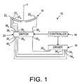
- FIG. 1is a schematic diagram of a focused ultrasound system, in accordance with the present invention.
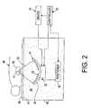
- FIG. 2is a schematic side view of a patient on a water-filled table being treated using a focused ultrasound system, such as that shown in FIG. 1 .
- FIGS. 3A-3Care exemplary tables, showing desired phase shift values for transducer elements of a transducer array, associating the desired phase shift values with phase shift values assigned to output channels of a driver, and a switch configuration for connecting the transducer elements to respective output channels, respectively.
- FIGS. 1 and 2depict an exemplary embodiment of a focused ultrasound system 10 , including a transducer array 14 , a driver 16 , a controller 18 , and a switch 20 , in accordance with the present invention.
- the transducer array 14may deliver acoustic energy represented by acoustic beam 15 into a target region 92 , e.g., a benign or malignant tumor or other tissue volume, within a patient's body 90 , to ablate or otherwise treat tissue within the target region 92 .
- the switch 20connects the transducer array 14 to the driver 16 and/or to the controller 18 in order to steer and/or focus the acoustic energy transmitted by the transducer array 14 in a desired manner.
- the transducer array 14generally includes multiple transducer elements 22 arranged in a pattern on a substrate 24 .
- the substrate 24may be a frame, a planar or curved structure, and the like, onto which the transducer elements 22 may be mounted or otherwise provided.
- the transducer array 14may have a concave or bowl shape, such as a “spherical cap” shape, i.e., having a substantially constant radius of curvature such that the transducer array 14 has an inside surface defining a portion of a sphere, although alternatively, the substrate 24 may define a non-spherical surface.
- the transducer array 14may have an outer diameter between about eight and sixteen centimeters (8-16 cm), and a radius of curvature between about eight and twenty centimeters (8-20 cm).
- the transducer array 14may have a substantially flat configuration (not shown), may include an outer perimeter that is generally circular, and/or may have a square, linear, hexagonal or other symmetrical or asymmetrical shape (not shown).
- the transducer array 14may be divided into any desired number “n” of transducer elements 22 1 , 22 2 22 3 , . . . 22 n , as seen in FIG. 1 , and/or into a plurality of subsets of transducer elements, each with a plurality of transducer elements.
- the transducer array 14may be divided into concentric rings and/or circumferential sectors to provide the transducer elements 22 .
- the transducer array 14may include between ten and forty (10-40) rings and between four and sixteen (4-16) sectors.
- the transducer 14may include transducer elements 22 having a variety of geometric shapes, such as hexagons, triangles, circles, squares, and the like (not shown).
- the transducer elements 22may be disposed about a central axis “z,” preferably but not necessarily, in a substantially uniform or symmetrical configuration. Preferably, although not necessarily, the transducer elements 22 have substantially the same surface area as one another and/or may have similar or different sizes and shapes than one another. Additional information on the construction of transducer arrays appropriate for use with the present invention may be found, for example, in co-pending application Ser. No. 09/884,206, filed Jun. 19, 2000. The disclosures of this application and any references cited therein are expressly incorporated herein by reference.
- a transducer array 14 in accordance with the present inventionmay include many transducer elements, e.g., hundreds or thousands of transducer elements built as a single dish, or as an assembly of many individual tiles, assembled into a structure to provide a combined array.
- the transducer array 14includes between about two hundred and ten thousand (200-10,000) transducer elements 22 .
- the transducer elements 22may have a width, diameter, or other maximum cross-sectional dimension across their surface area that is on the order of the wavelength of the acoustic energy that is transmitted by the transducer elements 22 .
- the transducer elements 22may have a cross-sectional dimension between about 0.8 and seven millimeters (0.8-7 mm), which are on the order of the wavelength of ultrasonic energy between about two and 0.2 Megahertz (2-0.2 MHz), respectively.
- the specific number of transducer elements and their sizes, however,is not important to the present invention, and the systems and methods discussed herein may be applicable to a transducer array 14 including a variety of different configurations of transducer elements 22 .
- the driver 16 and/or the controller 18may be coupled to the transducer array 14 via the switch 20 for causing the transducer elements 22 to transmit acoustic energy.
- the driver 16includes an oscillator and/or other component(s) (not shown) enabling the driver 16 to generate electrical drive signals, which may be controlled by the controller 18 .
- the driver 16may generate drive signals in the ultrasound frequency spectrum that may be as low as twenty kilohertz (20 kHz), and that typically range from about 0.3 to three Megahertz (0.3-3.0 MHz).
- the driver 16provides radio frequency (RF) drive signals, for example, between about 0.3-3.0 MHz, and more preferably between about 0.5-2.5 MHz.
- RFradio frequency
- the transducer elements 22convert the electrical drive signals into vibrational energy, as represented by the acoustic beam 15 .
- Exemplary drivers and/or controllers that may be used to generate sets of drive signalsare disclosed in U.S. Pat. No. 6,506,154, the disclosure of which is expressly incorporated herein by reference.
- the driver 16 and/or controller 18may be separate from or integral components of the transducer array 14 , and/or may be separate components from or integral with one another. It will be appreciated by one skilled in the art that the operations performed by the driver 16 and/or controller 18 may be performed by one or more controllers, processors, and/or other electronic components, including software or hardware components.
- the driver 16includes a number “m” of output channels 34 that provide respective sets of drive signals (s 1 , s 2 , s 3 , . . . s m ) having respective phase shift values ( ⁇ 1 , ⁇ 2 , ⁇ 3 , . . . ⁇ m ).
- the number “m” of output channels 34is generally substantially less than the number “n” of transducer elements 22 , and preferably “m” is orders of magnitude smaller than “n.” For example, “n”/“m” could be between about ten and one hundred (10-100), or even more than one hundred (100).
- the switch 20generally includes an “m” number of inputs 36 , an “n” number of outputs 38 , and a plurality of switches (not shown) therein.
- the “m” output channels 34 from the driver 16may be coupled to the “m” inputs 36 of the switch 20 , respectively, and the “n” outputs 38 of the switch 20 may be coupled to the “n” transducer elements 22 , respectively.
- the switch 20may allow respective inputs 36 to be selectively connected to one or more respective outputs 38 , thereby delivering sets of drive signals with different phase shift values to respective transducer elements 22 .
- the switch 20may be a cross-point matrix, a multistage interconnection network (“MIN”), or other switching device enabling multiple inputs to be selectively connected to one or more respective outputs, as is known in the art.
- the switch 20is mounted to the transducer array 14 , e.g., to the substrate 24 opposite the transducer elements 22 , as shown in FIG. 2 .
- Wires, cables, conductive paths, or other conductors(generally referred to herein as “leads,” not shown) may extend between the outputs 38 of the switch 20 and respective transducer elements 22 , e.g., along the substrate 24 or otherwise contained within the transducer array 14 .
- the leadsshould electrical connectivity, while mechanically isolating the transducer vibrating elements from the substrate 24 .
- the switch 20may be mounted in close proximity to the transducer array 14 , i.e., not directly mounted to the substrate 24 .
- Wires or other leadsmay extend from the inputs 36 of the switch 20 to the driver 16 .
- This arrangementmay substantially simplify wiring of the transducer array 14 , since only “m” leads are required for the cable(s) connecting the transducer array 14 to the driver 16 , rather than “n” leads, as would be required if each transducer element 22 were separately connected to the driver 16 .
- the switch 20should be made from nonmagnetic materials, as is well known to those skilled in the art.
- the leadsmay include one or more connectors (not shown) for detachably connecting them to any of the components described herein, as is known in the art.
- the controller 18may control the driver 16 , e.g., to control one or more characteristics of the drive signals generated by the driver 16 .
- the controller 18may control an amplitude of the drive signals, and, consequently, the intensity or power of the acoustic waves transmitted by the transducer 14 , as is known in the art, and/or the phase allocation to each of the “m” leads 34 leaving the driver 16 .
- the controller 18may also control and/or assign phase shift values to the drive signals in order to steer and/or focus the acoustic energy in a desired manner.
- the controller 18may divide a full cycle (360° or 2n radians) by the number of output channels 34 of the driver 16 and assign sequential phase shift values, e.g., between 0° and 360° to the sets of drive signals.
- the controller 18may assign phase shift values using other methodologies, and cause the driver 16 to generate sets of drive signals based upon the assigned phase shift values.
- controller 18may be configured to generate one or more tables relating sets of drive signals to the transducer elements 22 that may be used by the system 10 .
- the controller 18may include one or more processors (not shown) for generating the data for the tables, and/or memory (also not shown) for storing the one or more tables.
- the controller 18may generate respective desired phase shift values for the transducer elements 22 based upon parameters for a particular treatment, and create a first table of desired phase shift values for the transducer elements 22 .
- the data in the first tablemay be based upon a desired focal depth, a desired focal zone shape, compensation for tissue aberrations encountered during a particular treatment, compensation for variances in the relative impedance of the transducer elements, and/or compensation for geometric inaccuracies in positioning the transducer elements 22 relative to one another on the transducer array 14 .
- a hypothetical set of desired phase shift values for a transducer array including “n” elementsis shown in FIG. 3A .
- separate tablesmay be generated for one or more of these parameters, e.g., for different beam paths, focal zone locations, and/or focal depths.
- one or more sets of tablesmay be loaded, e.g., to reconfigure the switch 20 during a procedure. This may provide the controller 18 with even greater flexibility to switch steering and focusing dynamically.
- the controller 18may assign phase shift values to each of the transducer elements 22 based upon a desired location for the focal zone 17 of the transducer array 14 .
- the controller 18may assign phase shift values to transducer elements 22 based upon their circumferential location around the central axis “z” and/or their radial distance from the central axis “z.” These phase shift values may change the size and/or shape of the resulting focal zone 17 , and/or may adjust the focal depth, as is known in the art.
- controller 18may assign phase shift values to the transducer elements 22 that move the focal zone laterally relative to the central axis “z,” i.e., to steer the focal zone away from the central axis “z,” and/or to generate multiple focal zones simultaneously.
- phase shift valuesto the transducer elements 22 that move the focal zone laterally relative to the central axis “z,” i.e., to steer the focal zone away from the central axis “z,” and/or to generate multiple focal zones simultaneously.
- the controller 18may compensate for tissue aberrations, i.e., phase shifts that may occur due to the acoustic energy from respective transducer elements 22 traveling along different acoustic paths having different densities, e.g., when the acoustic energy passes through different tissue structures.
- the controller 18may analyze an acoustic path from each of the transducer elements 22 through intervening tissue structures to the target region 92 , e.g., using magnetic resonance imaging, ultrasound imaging, and the like. Exemplary systems and methods for compensating for tissue aberrations are disclosed in application Ser. Nos. 09/724,817, filed Nov. 28, 2000, and application Ser. No. 10/190,787, filed Jul.
- phase shift values for compensating for tissue aberrationsmay be added to any other phase shift values assigned by the controller 18 , e.g., those desired to control the size and/or location of the resulting focal zone, to provide phase corrections correcting for physical tolerances in the transducer structure, and/or to compensate for impedance variations between the different elements, as is known in the art.
- the controller 18may assign sets of drive signals to the transducer elements 22 to create a second table of assigned drive signal-transducer element relationships. For example, the controller 18 may compare the phase shift values of the sets of drive signals to the desired phase shift values for the transducer elements 22 , and assign each of the transducer elements 22 to a set of drive signals that has a phase shift value that approximates the desired phase shift value for the respective transducer element. The controller 18 may round the desired phase shift value for each of the transducer elements 22 off to the nearest phase shift value corresponding to one of the sets of drive signals.
- the desired phase shift valuescould be truncated or associated with respective sets of drive signals using other methodologies.
- An exemplary table showing transducer elements assigned to respective output channels, and consequently, respective phase shift valuesis shown in FIG. 3B .
- the controller 18may generate a third table to control the switch 20 , e.g., based upon the drive signal-transducer element assignments in the second table. For example, if the switch 20 is a cross-point matrix, the third table may instruct the cross-point matrix to configure its switches in a particular manner to connect the inputs 36 to respective outputs 38 in order to connect the transducer elements 22 to the output channels 34 corresponding to their assigned sets of drive signals.
- the controller 18may control the switch 20 directly, or the switch 20 may include its own controller (not shown).
- An exemplary table identifying inputs and outputs of a switch to connect to one anotheris shown in FIG. 3B , based upon the data from FIGS. 3A and 3B discussed above.
- the controller 18may also control a physical position or orientation of the transducer array 14 .
- the system 10may include a mechanical positioner 48 connected to the transducer array 14 that may move the transducer array 14 in one or more dimensions, and preferably in any of three orthogonal directions.
- Exemplary transducers and positioning systemsare disclosed in co-pending application Ser. Nos. 09/556,095 and 09/557,078, both filed Apr. 21, 2000, and application Ser. No. 09/628,964, filed Jul. 31, 2000. The disclosures of these references and any others cited therein are expressly incorporated herein by reference.
- the transducer array 14may be focused electronically, mechanically, or using a combination of the two, and/or the focus zone may be moved within the target 92 electronically, mechanically, or using a combination of the two.
- the transducer array 14may be mounted within a casing or chamber 40 filled with degassed water or similar acoustically propagating fluid.
- the chamber 40may be located within a table 42 upon which a patient 90 may be disposed, or within a fluid-filled bag mounted on a movable arm that may be placed against a patient's body (not shown).
- the top of the table 42generally includes a flexible membrane 44 that is substantially transparent to ultrasound, such as mylar, polyvinyl chloride (PVC), or other suitable plastic material.
- a fluid-filled bag 46may be provided on the membrane 44 that may conform easily to the contours of the patient 90 disposed on the table 42 , thereby acoustically coupling the patient 90 to the transducer array 14 within the chamber 40 .
- acoustic gel, water, or other fluidmay be provided between the patient 90 and the membrane 44 to facilitate further acoustic coupling between the transducer array 14 and the patient 90 , as is known to those skilled in the art.
- the system 10may include an imaging device (not shown) for monitoring the use of the system during treatment of a patient.
- the system 10may be placed within a magnetic resonance imaging (MRI) system, such as that disclosed in U.S. Pat. Nos. 5,247,935, 5,291,890, 5,368,031, 5,368,032, 5,443,068 issued to Cline et al., and U.S. Pat. Nos. 5,307,812, 5,323,779, 5,327,884 issued to Hardy et al., the disclosures of which are expressly incorporated herein by reference.
- an acoustic imaging devicemay be provided, or the transducer array 14 itself may be used for imaging, as is known to those skilled in the art.
- a patient 90may be disposed on the table 42 with water, ultrasonic conducting gel, and the like (not shown) applied between the patient 90 and the bag 46 or membrane 44 , thereby acoustically coupling the patient 90 with the transducer array 14 .
- the transducer array 14may be oriented generally towards a target tissue region 92 , e.g. within a tissue structure, such as a cancerous or benign tumor within an organ, e.g., a liver, kidney, pancreas, uterus, brain, and the like.
- the acoustic path from the transducer array 14 to the target tissue region 92may be analyzed, e.g., using MRI or ultrasound imaging, as explained above.
- the acoustic path from each of the transducer elements 22 to the target tissue region 92may be analyzed to determine tissue types or other characteristics that may affect the speed of the acoustic energy passing through intervening tissue between the transducer elements 22 and the target tissue region 92 .
- Phase shift valuesmay be determined for each of the transducer elements 22 to compensate for these variations in speed in order to maintain the focus of the acoustic energy substantially at the desired focal zone 17 .
- individual transducer elements 22may be deactivated (e.g., have their amplitude set to zero (0)) in order to prevent acoustic energy from being transmitted by the relevant transducer elements 22 .
- the controller 18may be instructed to generate a treatment procedure, which may involve a single or multiple “sonications” (i.e., finite time periods during which the transducer array 14 is activated to deliver acoustic energy to a focal zone at a particular location within the target tissue region 92 ).
- the controller 18 and/or the operatormay set the number and duration of sonications to be used to treat the target tissue region 92 .
- the controller 18may generate the tables described above and/or otherwise instruct the switch 20 in order to connect the output channels 34 of the driver 16 to respective transducer elements 22 .
- the controller 18may assign phase shift values to the sets of drive signals that will be provided at each of the output channels 34 of the driver 16 .
- the phase shift values of the sets of drive signalsmay be fixed, e.g., based upon phase errors required to achieve a predefined focus quality.
- continuous wave (CW) acoustic beam forming in phased arraysrequires the ability to control phase errors between different transducer elements to a particular level, e.g., better than ⁇ /10, where ⁇ is the wavelength of the acoustic energy defining the acoustic beam. Because phase corrections are modulo 2n, it would be desired to have phase accuracy better than 2n/10.
- phase error correctionswith as few as ten (10) phase values. It will be appreciated that more or fewer phase shift values, and consequently, output channels, may be provided. In an exemplary embodiment of a transducer array including two thousand (2,000) transducer elements, thirty two (32) phase values and output channels may be used.
- the controller 18may then determine desired phase shift values for the transducer elements 22 of the transducer array 14 , taking into account focal zone shape, focal depth, steering angle, equal power distribution between drive channels, and tissue aberrations, as discussed above.
- One or more tablesmay be generated assigning each of the transducer elements 22 to one of the output channels 34 , and the switch 20 may be set to connect the transducer elements 22 to the driver 16 based upon the generated tables.
- the driver 16may be activated in order to provide respective sets of drive signals to the transducer array 14 .
- the transducer elements 22transform the drive signals into acoustic energy, represented by energy beam 15 .
- the acoustic energy 15passes through the patient's body, the acoustic energy 15 is converted to heat at the focal zone 17 , thereby raising the temperature of tissue within focal zone 17 .
- the acoustic energymay be focused for sufficient time to raise the temperature of tissue within the focal zone 17 to necrose the tissue, while minimizing damage to surrounding tissue.
- the transducer array 14may be activated for about ten seconds or more, e.g., between about two and forty (2-40) seconds, and preferably between about four and twenty seconds. Once a sonication is completed, the transducer array 14 may be deactivated, for example, for sufficient time to allow heat absorbed by the patient's tissue to dissipate, e.g., for about sixty (60) seconds. The transducer array 14 may then be focused at another focal zone within the target tissue region 92 , for example, adjacent to the previous focal zone 17 , and the process repeated until the entire target tissue region 92 is ablated.
- the output channels 34 of the driver 16may be connected to multiple transducer elements 22 . This may substantially reduce the number of output channels 34 required for the transducer array 14 , thereby substantially simplifying connection between the driver 16 and the transducer array 14 .
- the system 10allows substantially more and smaller transducer elements to be provided for a given transducer array size and configuration, thereby enhancing the ability to steer the acoustic energy and focus the acoustic energy more precisely than conventional systems.
- systems and methods described hereinhave described ablating or otherwise treating tissue, the systems and methods of the present invention may also be used to perform other therapeutic or diagnostic procedures, e.g., ultrasound imaging and the like.
Landscapes
- Health & Medical Sciences (AREA)
- Engineering & Computer Science (AREA)
- Nuclear Medicine, Radiotherapy & Molecular Imaging (AREA)
- Multimedia (AREA)
- Acoustics & Sound (AREA)
- Biomedical Technology (AREA)
- Physics & Mathematics (AREA)
- Radiology & Medical Imaging (AREA)
- Life Sciences & Earth Sciences (AREA)
- Animal Behavior & Ethology (AREA)
- General Health & Medical Sciences (AREA)
- Public Health (AREA)
- Veterinary Medicine (AREA)
- Ultra Sonic Daignosis Equipment (AREA)
- Surgical Instruments (AREA)
Abstract
Description
Claims (9)
Priority Applications (1)
| Application Number | Priority Date | Filing Date | Title |
|---|---|---|---|
| US12/559,939US8002706B2 (en) | 2003-05-22 | 2009-09-15 | Acoustic beam forming in phased arrays including large numbers of transducer elements |
Applications Claiming Priority (2)
| Application Number | Priority Date | Filing Date | Title |
|---|---|---|---|
| US10/443,549US7611462B2 (en) | 2003-05-22 | 2003-05-22 | Acoustic beam forming in phased arrays including large numbers of transducer elements |
| US12/559,939US8002706B2 (en) | 2003-05-22 | 2009-09-15 | Acoustic beam forming in phased arrays including large numbers of transducer elements |
Related Parent Applications (1)
| Application Number | Title | Priority Date | Filing Date |
|---|---|---|---|
| US10/443,549ContinuationUS7611462B2 (en) | 2003-05-22 | 2003-05-22 | Acoustic beam forming in phased arrays including large numbers of transducer elements |
Publications (2)
| Publication Number | Publication Date |
|---|---|
| US20100056962A1 US20100056962A1 (en) | 2010-03-04 |
| US8002706B2true US8002706B2 (en) | 2011-08-23 |
Family
ID=33450444
Family Applications (2)
| Application Number | Title | Priority Date | Filing Date |
|---|---|---|---|
| US10/443,549Expired - LifetimeUS7611462B2 (en) | 2003-05-22 | 2003-05-22 | Acoustic beam forming in phased arrays including large numbers of transducer elements |
| US12/559,939Expired - LifetimeUS8002706B2 (en) | 2003-05-22 | 2009-09-15 | Acoustic beam forming in phased arrays including large numbers of transducer elements |
Family Applications Before (1)
| Application Number | Title | Priority Date | Filing Date |
|---|---|---|---|
| US10/443,549Expired - LifetimeUS7611462B2 (en) | 2003-05-22 | 2003-05-22 | Acoustic beam forming in phased arrays including large numbers of transducer elements |
Country Status (5)
| Country | Link |
|---|---|
| US (2) | US7611462B2 (en) |
| EP (1) | EP1624934B1 (en) |
| AT (1) | ATE485875T1 (en) |
| DE (1) | DE602004029779D1 (en) |
| WO (1) | WO2004103472A1 (en) |
Cited By (17)
| Publication number | Priority date | Publication date | Assignee | Title |
|---|---|---|---|---|
| US20090076392A1 (en)* | 2005-05-09 | 2009-03-19 | Mitsuhiro Oshiki | Ultrasonic Diagnostic Apparatus |
| US20100100015A1 (en)* | 2004-07-09 | 2010-04-22 | Boston Scientific Scimed, Inc. | Ultrasound systems and methods for treatng ischemic limbs or tissue affected by peripheral arterial disease |
| US20100125192A1 (en)* | 2008-11-17 | 2010-05-20 | Rajiv Chopra | Focused ultrasound system |
| US20130190603A1 (en)* | 2012-01-23 | 2013-07-25 | Rares Salomir | Method for ultrasound focal spot shaping |
| US8852103B2 (en) | 2011-10-17 | 2014-10-07 | Butterfly Network, Inc. | Transmissive imaging and related apparatus and methods |
| US8979871B2 (en) | 2009-08-13 | 2015-03-17 | Monteris Medical Corporation | Image-guided therapy of a tissue |
| US20150208946A1 (en)* | 2014-01-29 | 2015-07-30 | Stefan Popescu | Device for Positioning an Examination Object, Method for Creating an Image with the Aid of an Imaging System, and Imaging System |
| US9177543B2 (en) | 2009-08-26 | 2015-11-03 | Insightec Ltd. | Asymmetric ultrasound phased-array transducer for dynamic beam steering to ablate tissues in MRI |
| US9333038B2 (en) | 2000-06-15 | 2016-05-10 | Monteris Medical Corporation | Hyperthermia treatment and probe therefore |
| US9433383B2 (en) | 2014-03-18 | 2016-09-06 | Monteris Medical Corporation | Image-guided therapy of a tissue |
| US9504484B2 (en) | 2014-03-18 | 2016-11-29 | Monteris Medical Corporation | Image-guided therapy of a tissue |
| US9667889B2 (en) | 2013-04-03 | 2017-05-30 | Butterfly Network, Inc. | Portable electronic devices with integrated imaging capabilities |
| US9852727B2 (en) | 2010-04-28 | 2017-12-26 | Insightec, Ltd. | Multi-segment ultrasound transducers |
| US10327830B2 (en) | 2015-04-01 | 2019-06-25 | Monteris Medical Corporation | Cryotherapy, thermal therapy, temperature modulation therapy, and probe apparatus therefor |
| US10675113B2 (en) | 2014-03-18 | 2020-06-09 | Monteris Medical Corporation | Automated therapy of a three-dimensional tissue region |
| US10835215B2 (en) | 2012-09-12 | 2020-11-17 | Convergent Life Sciences, Inc. | Method and apparatus for laser ablation under ultrasound guidance |
| US12168055B2 (en) | 2019-05-29 | 2024-12-17 | Sonalasense, Inc. | Sonosensitization |
Families Citing this family (67)
| Publication number | Priority date | Publication date | Assignee | Title |
|---|---|---|---|---|
| US6618620B1 (en) | 2000-11-28 | 2003-09-09 | Txsonics Ltd. | Apparatus for controlling thermal dosing in an thermal treatment system |
| US8088067B2 (en) | 2002-12-23 | 2012-01-03 | Insightec Ltd. | Tissue aberration corrections in ultrasound therapy |
| US7611462B2 (en) | 2003-05-22 | 2009-11-03 | Insightec-Image Guided Treatment Ltd. | Acoustic beam forming in phased arrays including large numbers of transducer elements |
| US7377900B2 (en)* | 2003-06-02 | 2008-05-27 | Insightec - Image Guided Treatment Ltd. | Endo-cavity focused ultrasound transducer |
| US20110071381A1 (en)* | 2003-10-15 | 2011-03-24 | Robert Tien | Method and system for leading macromolecule substances into living target cells |
| TWI243696B (en)* | 2003-10-15 | 2005-11-21 | Der-Yang Tien | System for introducing macromolecule substance into living target cell |
| US20050148874A1 (en)* | 2003-12-19 | 2005-07-07 | Brock-Fisher George A. | Ultrasonic imaging aberration correction with microbeamforming |
| US8409099B2 (en) | 2004-08-26 | 2013-04-02 | Insightec Ltd. | Focused ultrasound system for surrounding a body tissue mass and treatment method |
| US10864385B2 (en) | 2004-09-24 | 2020-12-15 | Guided Therapy Systems, Llc | Rejuvenating skin by heating tissue for cosmetic treatment of the face and body |
| US8444562B2 (en) | 2004-10-06 | 2013-05-21 | Guided Therapy Systems, Llc | System and method for treating muscle, tendon, ligament and cartilage tissue |
| US8535228B2 (en) | 2004-10-06 | 2013-09-17 | Guided Therapy Systems, Llc | Method and system for noninvasive face lifts and deep tissue tightening |
| US11235179B2 (en) | 2004-10-06 | 2022-02-01 | Guided Therapy Systems, Llc | Energy based skin gland treatment |
| US11883688B2 (en) | 2004-10-06 | 2024-01-30 | Guided Therapy Systems, Llc | Energy based fat reduction |
| US8690779B2 (en) | 2004-10-06 | 2014-04-08 | Guided Therapy Systems, Llc | Noninvasive aesthetic treatment for tightening tissue |
| US11724133B2 (en) | 2004-10-07 | 2023-08-15 | Guided Therapy Systems, Llc | Ultrasound probe for treatment of skin |
| US8442623B2 (en)* | 2004-10-13 | 2013-05-14 | Suros Surgical Systems, Inc. | Site marker visible under multiple modalities |
| US8060183B2 (en) | 2004-10-13 | 2011-11-15 | Suros Surgical Systems, Inc. | Site marker visible under multiple modalities |
| US8280486B2 (en)* | 2004-10-13 | 2012-10-02 | Suros Surgical Systems, Inc. | Site marker visable under multiple modalities |
| US8433391B2 (en)* | 2004-10-13 | 2013-04-30 | Suros Surgical Systems, Inc. | Site marker |
| US20060079805A1 (en)* | 2004-10-13 | 2006-04-13 | Miller Michael E | Site marker visable under multiple modalities |
| US20070016039A1 (en)* | 2005-06-21 | 2007-01-18 | Insightec-Image Guided Treatment Ltd. | Controlled, non-linear focused ultrasound treatment |
| JP5087007B2 (en) | 2005-11-23 | 2012-11-28 | インサイテック・リミテッド | Hierarchical switching ultra high density ultrasonic array |
| US8235901B2 (en) | 2006-04-26 | 2012-08-07 | Insightec, Ltd. | Focused ultrasound system with far field tail suppression |
| US20100030076A1 (en)* | 2006-08-01 | 2010-02-04 | Kobi Vortman | Systems and Methods for Simultaneously Treating Multiple Target Sites |
| US8251908B2 (en) | 2007-10-01 | 2012-08-28 | Insightec Ltd. | Motion compensated image-guided focused ultrasound therapy system |
| EP2250286A1 (en)* | 2008-02-15 | 2010-11-17 | Life Technologies Corporation | Methods and compositions for shearing of polymers by sonication |
| KR20110091832A (en) | 2008-06-06 | 2011-08-12 | 얼테라, 인크 | Tissue Imaging and Treatment Systems |
| US12102473B2 (en) | 2008-06-06 | 2024-10-01 | Ulthera, Inc. | Systems for ultrasound treatment |
| US20100125225A1 (en)* | 2008-11-19 | 2010-05-20 | Daniel Gelbart | System for selective ultrasonic ablation |
| US8425424B2 (en) | 2008-11-19 | 2013-04-23 | Inightee Ltd. | Closed-loop clot lysis |
| US20100179425A1 (en)* | 2009-01-13 | 2010-07-15 | Eyal Zadicario | Systems and methods for controlling ultrasound energy transmitted through non-uniform tissue and cooling of same |
| US8488813B2 (en)* | 2009-04-01 | 2013-07-16 | Avago Technologies General Ip (Singapore) Pte. Ltd. | Reconfigurable acoustic transducer device |
| US8617073B2 (en) | 2009-04-17 | 2013-12-31 | Insightec Ltd. | Focusing ultrasound into the brain through the skull by utilizing both longitudinal and shear waves |
| WO2010143072A1 (en) | 2009-06-10 | 2010-12-16 | Insightec Ltd. | Acoustic-feedback power control during focused ultrasound delivery |
| KR101143645B1 (en)* | 2009-07-29 | 2012-05-09 | 주세은 | Transcranial low-intensity ultrasound delivery device and non-invasive modulation of brain function |
| US9623266B2 (en) | 2009-08-04 | 2017-04-18 | Insightec Ltd. | Estimation of alignment parameters in magnetic-resonance-guided ultrasound focusing |
| US9289154B2 (en) | 2009-08-19 | 2016-03-22 | Insightec Ltd. | Techniques for temperature measurement and corrections in long-term magnetic resonance thermometry |
| EP2489034B1 (en) | 2009-10-14 | 2016-11-30 | Insightec Ltd. | Mapping ultrasound transducers |
| US8368401B2 (en) | 2009-11-10 | 2013-02-05 | Insightec Ltd. | Techniques for correcting measurement artifacts in magnetic resonance thermometry |
| DE102010010821A1 (en)* | 2010-03-10 | 2011-09-15 | Siemens Aktiengesellschaft | In a bloodstream fixable element that is provided with biomarkers |
| US8932237B2 (en)* | 2010-04-28 | 2015-01-13 | Insightec, Ltd. | Efficient ultrasound focusing |
| WO2011156624A2 (en)* | 2010-06-09 | 2011-12-15 | Regents Of The University Of Minnesota | Dual mode ultrasound transducer (dmut) system and method for controlling delivery of ultrasound therapy |
| EP2441492A1 (en)* | 2010-10-14 | 2012-04-18 | Koninklijke Philips Electronics N.V. | High intensity focused ultrasound system, computer-implemented method, and computer program product |
| WO2012049612A2 (en)* | 2010-10-14 | 2012-04-19 | Koninklijke Philips Electronics N.V. | High intensity focused ultrasound system, computer-implemented method, and computer program product |
| US9981148B2 (en) | 2010-10-22 | 2018-05-29 | Insightec, Ltd. | Adaptive active cooling during focused ultrasound treatment |
| US12402802B2 (en) | 2011-08-31 | 2025-09-02 | Insightec Ltd. | Avoiding MRI-interference with co-existing systems |
| US9581627B2 (en)* | 2012-05-21 | 2017-02-28 | General Electric Company | Method and system for tomographic imaging |
| BR112015006947A8 (en) | 2012-10-01 | 2018-02-06 | Koninklijke Philips Nv | MEDICAL EQUIPMENT, COMPUTER PROGRAM PRODUCT, AND METHOD FOR OPERATING MEDICAL EQUIPMENT |
| EP2914342B1 (en)* | 2012-11-05 | 2017-08-30 | Koninklijke Philips N.V. | Medical apparatus for determining a maximum energy map |
| CN104027893B (en) | 2013-03-08 | 2021-08-31 | 奥赛拉公司 | Apparatus and method for multifocal ultrasound therapy |
| CN103194986B (en)* | 2013-04-01 | 2015-09-16 | 西安中交万向科技股份有限公司 | A kind of method of absorbent lined barrier and offset noise |
| WO2015160708A1 (en) | 2014-04-18 | 2015-10-22 | Ulthera, Inc. | Band transducer ultrasound therapy |
| WO2016097867A2 (en)* | 2014-12-19 | 2016-06-23 | Université Pierre Et Marie Curie (Paris 6) | Implantable ultrasound generating treating device for brain treatment, apparatus comprising such device and method implementing such device |
| PL3981466T3 (en) | 2016-08-16 | 2023-11-20 | Ulthera, Inc. | Systems and methods for cosmetic ultrasound treatment of skin |
| CN110753516B (en)* | 2016-12-30 | 2023-02-14 | 阿普劳德医疗公司 | System and method for detecting and aligning an in situ beam to a target using wide beam, low frequency (< 1 MHz) ultrasound |
| US12179042B2 (en) | 2017-02-23 | 2024-12-31 | Oron Zachar | Transcranial ultrasound focusing |
| US10404364B2 (en)* | 2017-05-01 | 2019-09-03 | Teradyne, Inc. | Switch matrix system |
| US11272904B2 (en)* | 2017-06-20 | 2022-03-15 | Insightec, Ltd. | Ultrasound focusing using a cross-point switch matrix |
| EP3645118B1 (en) | 2017-06-29 | 2023-11-29 | Insightec Ltd. | Simulation-based drug treatment planning |
| US10925628B2 (en)* | 2017-09-18 | 2021-02-23 | Novuson Surgical, Inc. | Tissue engagement apparatus for theapeutic ultrasound apparatus and method |
| TWI797235B (en) | 2018-01-26 | 2023-04-01 | 美商奧賽拉公司 | Systems and methods for simultaneous multi-focus ultrasound therapy in multiple dimensions |
| US11944849B2 (en) | 2018-02-20 | 2024-04-02 | Ulthera, Inc. | Systems and methods for combined cosmetic treatment of cellulite with ultrasound |
| US11596812B2 (en) | 2018-04-06 | 2023-03-07 | Regents Of The University Of Minnesota | Wearable transcranial dual-mode ultrasound transducers for neuromodulation |
| US11684807B2 (en)* | 2018-12-27 | 2023-06-27 | Insightec Ltd. | Optimization of transducer configurations in ultrasound procedures |
| US12377293B2 (en) | 2019-07-15 | 2025-08-05 | Ulthera, Inc. | Systems and methods for measuring elasticity with imaging of ultrasound multi-focus shearwaves in multiple dimensions |
| WO2023180811A2 (en) | 2022-03-22 | 2023-09-28 | Insightec Ltd. | Monitoring tissue permeability during ultrasound procedures |
| CN116712686A (en)* | 2023-06-25 | 2023-09-08 | 深圳半岛医疗有限公司 | Large focal area ultrasonic therapeutic apparatus |
Citations (179)
| Publication number | Priority date | Publication date | Assignee | Title |
|---|---|---|---|---|
| US2795709A (en) | 1953-12-21 | 1957-06-11 | Bendix Aviat Corp | Electroplated ceramic rings |
| US3142035A (en) | 1960-02-04 | 1964-07-21 | Harris Transducer Corp | Ring-shaped transducer |
| US3942150A (en) | 1974-08-12 | 1976-03-02 | The United States Of America As Represented By The Secretary Of The Navy | Correction of spatial non-uniformities in sonar, radar, and holographic acoustic imaging systems |
| US3974475A (en) | 1971-10-07 | 1976-08-10 | Hoffmann-La Roche Inc. | Method of and apparatus for focusing ultrasonic waves in a focal line |
| US3992693A (en) | 1972-12-04 | 1976-11-16 | The Bendix Corporation | Underwater transducer and projector therefor |
| US4000493A (en) | 1971-04-12 | 1976-12-28 | Eastman Kodak Company | Acoustooptic scanner apparatus and method |
| US4339952A (en) | 1979-04-26 | 1982-07-20 | Ontario Cancer Institute | Cylindrical transducer ultrasonic scanner |
| US4454597A (en) | 1982-05-03 | 1984-06-12 | The United States Of America As Represented By The Secretary Of The Navy | Conformal array compensating beamformer |
| US4478083A (en) | 1982-06-30 | 1984-10-23 | Siemens Aktiengesellschaft | Plane reconstruction ultrasound tomography device |
| US4505156A (en) | 1983-06-21 | 1985-03-19 | Sound Products Company L.P. | Method and apparatus for switching multi-element transducer arrays |
| US4526168A (en) | 1981-05-14 | 1985-07-02 | Siemens Aktiengesellschaft | Apparatus for destroying calculi in body cavities |
| US4537074A (en) | 1983-09-12 | 1985-08-27 | Technicare Corporation | Annular array ultrasonic transducers |
| US4549533A (en) | 1984-01-30 | 1985-10-29 | University Of Illinois | Apparatus and method for generating and directing ultrasound |
| US4858597A (en) | 1983-06-01 | 1989-08-22 | Richard Wolf Gmbh | Piezoelectric transducer for the destruction of concretions within an animal body |
| US4865042A (en) | 1985-08-16 | 1989-09-12 | Hitachi, Ltd. | Ultrasonic irradiation system |
| US4888746A (en) | 1987-09-24 | 1989-12-19 | Richard Wolf Gmbh | Focussing ultrasound transducer |
| US4889122A (en) | 1985-11-29 | 1989-12-26 | Aberdeen University | Divergent ultrasound arrays |
| US4893284A (en) | 1988-05-27 | 1990-01-09 | General Electric Company | Calibration of phased array ultrasound probe |
| US4937767A (en) | 1986-12-24 | 1990-06-26 | Hewlett-Packard Company | Method and apparatus for adjusting the intensity profile of an ultrasound beam |
| US5209221A (en) | 1988-03-01 | 1993-05-11 | Richard Wolf Gmbh | Ultrasonic treatment of pathological tissue |
| US5247935A (en) | 1992-03-19 | 1993-09-28 | General Electric Company | Magnetic resonance guided focussed ultrasound surgery |
| US5271400A (en) | 1992-04-01 | 1993-12-21 | General Electric Company | Tracking system to monitor the position and orientation of a device using magnetic resonance detection of a sample contained within the device |
| US5275165A (en) | 1992-11-06 | 1994-01-04 | General Electric Company | Magnetic resonance guided ultrasound therapy system with inclined track to move transducers in a small vertical space |
| US5291890A (en) | 1991-08-29 | 1994-03-08 | General Electric Company | Magnetic resonance surgery using heat waves produced with focussed ultrasound |
| US5307816A (en) | 1991-08-21 | 1994-05-03 | Kabushiki Kaisha Toshiba | Thrombus resolving treatment apparatus |
| US5307812A (en) | 1993-03-26 | 1994-05-03 | General Electric Company | Heat surgery system monitored by real-time magnetic resonance profiling |
| US5318025A (en) | 1992-04-01 | 1994-06-07 | General Electric Company | Tracking system to monitor the position and orientation of a device using multiplexed magnetic resonance detection |
| US5329930A (en) | 1993-10-12 | 1994-07-19 | General Electric Company | Phased array sector scanner with multiplexed acoustic transducer elements |
| US5368032A (en) | 1993-11-09 | 1994-11-29 | General Electric Company | Manually positioned focussed energy system guided by medical imaging |
| US5368031A (en) | 1993-08-29 | 1994-11-29 | General Electric Company | Magnetic resonance surgery using heat waves produced with a laser fiber |
| US5379642A (en) | 1993-07-19 | 1995-01-10 | Diasonics Ultrasound, Inc. | Method and apparatus for performing imaging |
| US5391140A (en) | 1993-01-29 | 1995-02-21 | Siemens Aktiengesellschaft | Therapy apparatus for locating and treating a zone in the body of a life form with acoustic waves |
| US5413550A (en) | 1993-07-21 | 1995-05-09 | Pti, Inc. | Ultrasound therapy system with automatic dose control |
| US5443068A (en) | 1994-09-26 | 1995-08-22 | General Electric Company | Mechanical positioner for magnetic resonance guided ultrasound therapy |
| US5474071A (en) | 1991-03-05 | 1995-12-12 | Technomed Medical Systems | Therapeutic endo-rectal probe and apparatus constituting an application thereof for destroying cancer tissue, in particular of the prostate, and preferably in combination with an imaging endo-cavitary-probe |
| US5485839A (en) | 1992-02-28 | 1996-01-23 | Kabushiki Kaisha Toshiba | Method and apparatus for ultrasonic wave medical treatment using computed tomography |
| US5490840A (en) | 1994-09-26 | 1996-02-13 | General Electric Company | Targeted thermal release of drug-polymer conjugates |
| US5507790A (en) | 1994-03-21 | 1996-04-16 | Weiss; William V. | Method of non-invasive reduction of human site-specific subcutaneous fat tissue deposits by accelerated lipolysis metabolism |
| US5520188A (en) | 1994-11-02 | 1996-05-28 | Focus Surgery Inc. | Annular array transducer |
| US5526814A (en) | 1993-11-09 | 1996-06-18 | General Electric Company | Automatically positioned focussed energy system guided by medical imaging |
| US5549638A (en) | 1994-05-17 | 1996-08-27 | Burdette; Everette C. | Ultrasound device for use in a thermotherapy apparatus |
| US5553618A (en) | 1993-03-12 | 1996-09-10 | Kabushiki Kaisha Toshiba | Method and apparatus for ultrasound medical treatment |
| US5573497A (en) | 1994-11-30 | 1996-11-12 | Technomed Medical Systems And Institut National | High-intensity ultrasound therapy method and apparatus with controlled cavitation effect and reduced side lobes |
| US5582578A (en) | 1995-08-01 | 1996-12-10 | Duke University | Method for the comminution of concretions |
| US5590653A (en) | 1993-03-10 | 1997-01-07 | Kabushiki Kaisha Toshiba | Ultrasonic wave medical treatment apparatus suitable for use under guidance of magnetic resonance imaging |
| US5601526A (en) | 1991-12-20 | 1997-02-11 | Technomed Medical Systems | Ultrasound therapy apparatus delivering ultrasound waves having thermal and cavitation effects |
| US5605154A (en) | 1995-06-06 | 1997-02-25 | Duke University | Two-dimensional phase correction using a deformable ultrasonic transducer array |
| US5617371A (en) | 1995-02-08 | 1997-04-01 | Diagnostic/Retrieval Systems, Inc. | Method and apparatus for accurately determing the location of signal transducers in a passive sonar or other transducer array system |
| US5617857A (en) | 1995-06-06 | 1997-04-08 | Image Guided Technologies, Inc. | Imaging system having interactive medical instruments and methods |
| US5643179A (en) | 1993-12-28 | 1997-07-01 | Kabushiki Kaisha Toshiba | Method and apparatus for ultrasonic medical treatment with optimum ultrasonic irradiation control |
| US5662170A (en) | 1994-11-22 | 1997-09-02 | Baker Hughes Incorporated | Method of drilling and completing wells |
| US5665054A (en) | 1994-01-27 | 1997-09-09 | Technomed Medical Systems S.A. | Control method for hyperthermia treatment apparatus using ultrasound |
| US5676673A (en) | 1994-09-15 | 1997-10-14 | Visualization Technology, Inc. | Position tracking and imaging system with error detection for use in medical applications |
| US5687729A (en) | 1994-06-22 | 1997-11-18 | Siemens Aktiengesellschaft | Source of therapeutic acoustic waves introducible into the body of a patient |
| US5694936A (en) | 1994-09-17 | 1997-12-09 | Kabushiki Kaisha Toshiba | Ultrasonic apparatus for thermotherapy with variable frequency for suppressing cavitation |
| US5711300A (en) | 1995-08-16 | 1998-01-27 | General Electric Company | Real time in vivo measurement of temperature changes with NMR imaging |
| US5739625A (en) | 1994-05-09 | 1998-04-14 | The Secretary Of State For Defence In Her Britannic Majesty's Government Of The United Kingdom Of Great Britain And Northern Island | Segmented ring transducers |
| US5752515A (en) | 1996-08-21 | 1998-05-19 | Brigham & Women's Hospital | Methods and apparatus for image-guided ultrasound delivery of compounds through the blood-brain barrier |
| US5759162A (en) | 1992-03-10 | 1998-06-02 | Siemens Aktiengesellschaft | Method and apparatus for ultrasound tissue therapy |
| US5769790A (en) | 1996-10-25 | 1998-06-23 | General Electric Company | Focused ultrasound surgery system guided by ultrasound imaging |
| US5810008A (en) | 1996-12-03 | 1998-09-22 | Isg Technologies Inc. | Apparatus and method for visualizing ultrasonic images |
| US5873845A (en) | 1997-03-17 | 1999-02-23 | General Electric Company | Ultrasound transducer with focused ultrasound refraction plate |
| US5938600A (en) | 1995-12-14 | 1999-08-17 | U.S. Philips Corporation | Method and device for heating by means of ultrasound |
| US5938608A (en) | 1995-03-03 | 1999-08-17 | Siemens Aktiengesellschaft | Therapy apparatus for carrying out treatment with focused ultrasound |
| US5947900A (en) | 1998-04-13 | 1999-09-07 | General Electric Company | Dynamic scan plane tracking using MR position monitoring |
| US5984881A (en) | 1995-03-31 | 1999-11-16 | Kabushiki Kaisha Toshiba | Ultrasound therapeutic apparatus using a therapeutic ultrasonic wave source and an ultrasonic probe |
| JPH11313833A (en) | 1992-02-28 | 1999-11-16 | Toshiba Corp | Ultrasound therapy equipment |
| US6004269A (en) | 1993-07-01 | 1999-12-21 | Boston Scientific Corporation | Catheters for imaging, sensing electrical potentials, and ablating tissue |
| US6023636A (en) | 1997-06-25 | 2000-02-08 | Siemens Aktiengesellschaft | Magnetic resonance apparatus and method for determining the location of a positionable object in a subject |
| US6042556A (en) | 1998-09-04 | 2000-03-28 | University Of Washington | Method for determining phase advancement of transducer elements in high intensity focused ultrasound |
| US6071239A (en) | 1997-10-27 | 2000-06-06 | Cribbs; Robert W. | Method and apparatus for lipolytic therapy using ultrasound energy |
| US6113559A (en) | 1997-12-29 | 2000-09-05 | Klopotek; Peter J. | Method and apparatus for therapeutic treatment of skin with ultrasound |
| US6128522A (en) | 1997-05-23 | 2000-10-03 | Transurgical, Inc. | MRI-guided therapeutic unit and methods |
| US6128958A (en) | 1997-09-11 | 2000-10-10 | The Regents Of The University Of Michigan | Phased array system architecture |
| DE4345308C2 (en) | 1992-07-15 | 2001-02-01 | Fukuda Denshi Kk | Medical ultrasonic diagnosis system |
| US6193659B1 (en) | 1997-07-15 | 2001-02-27 | Acuson Corporation | Medical ultrasonic diagnostic imaging method and apparatus |
| US6242915B1 (en) | 1999-08-27 | 2001-06-05 | General Electric Company | Field-frequency lock system for magnetic resonance system |
| US6263230B1 (en) | 1997-05-08 | 2001-07-17 | Lucent Medical Systems, Inc. | System and method to determine the location and orientation of an indwelling medical device |
| US6289233B1 (en) | 1998-11-25 | 2001-09-11 | General Electric Company | High speed tracking of interventional devices using an MRI system |
| FR2806611A1 (en) | 2000-03-22 | 2001-09-28 | Hossein Kafai | Medical ultrasonic imaging device for examination of jaw region uses ultrasonic probes arranged on either side of face |
| US20010031922A1 (en) | 1999-12-23 | 2001-10-18 | Therus Corporation | Ultrasound transducers for imaging and therapy |
| US6309355B1 (en) | 1998-12-22 | 2001-10-30 | The Regents Of The University Of Michigan | Method and assembly for performing ultrasound surgery using cavitation |
| US6334846B1 (en) | 1995-03-31 | 2002-01-01 | Kabushiki Kaisha Toshiba | Ultrasound therapeutic apparatus |
| US20020035779A1 (en) | 2000-06-09 | 2002-03-28 | Robert Krieg | Method for three-dimensionally correcting distortions and magnetic resonance apparatus for implementing the method |
| US6392330B1 (en) | 2000-06-05 | 2002-05-21 | Pegasus Technologies Ltd. | Cylindrical ultrasound receivers and transceivers formed from piezoelectric film |
| US6397094B1 (en) | 1998-01-09 | 2002-05-28 | Koninklijke Philips Electronics N.V. | MR method utilizing microcoils situated in the examination zone |
| US20020082589A1 (en) | 2000-12-27 | 2002-06-27 | Insightec - Image Guided Treatement Ltd. | Systems and methods for ultrasound assisted lipolysis |
| US6419648B1 (en) | 2000-04-21 | 2002-07-16 | Insightec-Txsonics Ltd. | Systems and methods for reducing secondary hot spots in a phased array focused ultrasound system |
| US6424597B1 (en) | 1998-11-27 | 2002-07-23 | Commissariat A L'energie Atomique | Multielements ultrasonic contact transducer |
| US6425867B1 (en) | 1998-09-18 | 2002-07-30 | University Of Washington | Noise-free real time ultrasonic imaging of a treatment site undergoing high intensity focused ultrasound therapy |
| US6428532B1 (en) | 1998-12-30 | 2002-08-06 | The General Hospital Corporation | Selective tissue targeting by difference frequency of two wavelengths |
| US6461314B1 (en) | 1999-02-02 | 2002-10-08 | Transurgical, Inc. | Intrabody hifu applicator |
| US6475150B2 (en) | 2000-12-01 | 2002-11-05 | The Regents Of The University Of California | System and method for ultrasonic tomography |
| US6478739B1 (en) | 2001-05-11 | 2002-11-12 | The Procter & Gamble Company | Ultrasonic breast examination system |
| US6506154B1 (en) | 2000-11-28 | 2003-01-14 | Insightec-Txsonics, Ltd. | Systems and methods for controlling a phased array focused ultrasound system |
| US6506171B1 (en) | 2000-07-27 | 2003-01-14 | Insightec-Txsonics, Ltd | System and methods for controlling distribution of acoustic energy around a focal point using a focused ultrasound system |
| US6511428B1 (en) | 1998-10-26 | 2003-01-28 | Hitachi, Ltd. | Ultrasonic medical treating device |
| US6522142B1 (en) | 2001-12-14 | 2003-02-18 | Insightec-Txsonics Ltd. | MRI-guided temperature mapping of tissue undergoing thermal treatment |
| US6523272B1 (en) | 2001-08-03 | 2003-02-25 | George B. Morales | Measuring device and method of manufacture |
| US20030060820A1 (en) | 1997-07-08 | 2003-03-27 | Maguire Mark A. | Tissue ablation device assembly and method for electrically isolating a pulmonary vein ostium from an atrial wall |
| US6559644B2 (en) | 2001-05-30 | 2003-05-06 | Insightec - Txsonics Ltd. | MRI-based temperature mapping with error compensation |
| US6566878B1 (en) | 1999-09-09 | 2003-05-20 | Hitachi Medical Corporation | Magnetic resonance imaging device and method therefor |
| US6582381B1 (en) | 2000-07-31 | 2003-06-24 | Txsonics Ltd. | Mechanical positioner for MRI guided ultrasound therapy system |
| US6599256B1 (en) | 1999-09-10 | 2003-07-29 | Transurgical, Inc. | Occlusion of tubular anatomical structures by energy application |
| US6613005B1 (en) | 2000-11-28 | 2003-09-02 | Insightec-Txsonics, Ltd. | Systems and methods for steering a focused ultrasound array |
| US6613004B1 (en) | 2000-04-21 | 2003-09-02 | Insightec-Txsonics, Ltd. | Systems and methods for creating longer necrosed volumes using a phased array focused ultrasound system |
| US6612988B2 (en) | 2000-08-29 | 2003-09-02 | Brigham And Women's Hospital, Inc. | Ultrasound therapy |
| US6618620B1 (en) | 2000-11-28 | 2003-09-09 | Txsonics Ltd. | Apparatus for controlling thermal dosing in an thermal treatment system |
| US6618608B1 (en) | 1999-11-30 | 2003-09-09 | Txsonics, Ltd. | Thermal imaging of fat and muscle using a simultaneous phase and magnitude double echo sequence |
| US6626855B1 (en) | 1999-11-26 | 2003-09-30 | Therus Corpoation | Controlled high efficiency lesion formation using high intensity ultrasound |
| US6626854B2 (en) | 2000-12-27 | 2003-09-30 | Insightec - Txsonics Ltd. | Systems and methods for ultrasound assisted lipolysis |
| US20030187371A1 (en) | 2002-03-27 | 2003-10-02 | Insightec-Txsonics Ltd. | Systems and methods for enhanced focused ultrasound ablation using microbubbles |
| US6629929B1 (en) | 2002-11-08 | 2003-10-07 | Koninklijke Philips Electronics N.V. | Method and apparatus for automatically setting the transmit aperture and apodization of an ultrasound transducer array |
| US6666833B1 (en) | 2000-11-28 | 2003-12-23 | Insightec-Txsonics Ltd | Systems and methods for focussing an acoustic energy beam transmitted through non-uniform tissue medium |
| US6676601B1 (en) | 1999-05-26 | 2004-01-13 | Technomed Medical Systems, S.A. | Apparatus and method for location and treatment using ultrasound |
| US6679855B2 (en) | 2000-11-07 | 2004-01-20 | Gerald Horn | Method and apparatus for the correction of presbyopia using high intensity focused ultrasound |
| US20040030251A1 (en) | 2002-05-10 | 2004-02-12 | Ebbini Emad S. | Ultrasound imaging system and method using non-linear post-beamforming filter |
| US6705994B2 (en) | 2002-07-08 | 2004-03-16 | Insightec - Image Guided Treatment Ltd | Tissue inhomogeneity correction in ultrasound imaging |
| US20040068186A1 (en) | 2001-01-22 | 2004-04-08 | Kazunari Ishida | Ultrasonic therapeutic probe and ultrasonic device |
| US6733450B1 (en) | 2000-07-27 | 2004-05-11 | Texas Systems, Board Of Regents | Therapeutic methods and apparatus for use of sonication to enhance perfusion of tissue |
| US6735461B2 (en) | 2001-06-19 | 2004-05-11 | Insightec-Txsonics Ltd | Focused ultrasound system with MRI synchronization |
| US20040122323A1 (en) | 2002-12-23 | 2004-06-24 | Insightec-Txsonics Ltd | Tissue aberration corrections in ultrasound therapy |
| US6761691B2 (en) | 2000-07-21 | 2004-07-13 | Fuji Photo Film Co., Ltd. | Image forming method used in ultrasonic diagnosis, ultrasonic diagnostic apparatus, signal processing apparatus, and recording medium for recording signal processing program |
| US6770031B2 (en) | 2000-12-15 | 2004-08-03 | Brigham And Women's Hospital, Inc. | Ultrasound therapy |
| US6770039B2 (en) | 2001-11-09 | 2004-08-03 | Duke University | Method to reduce tissue injury in shock wave lithotripsy |
| US6788619B2 (en) | 2001-09-07 | 2004-09-07 | Shell Oil Company | Concentrating seismic energy in a selected target point in an underground formation |
| US6790180B2 (en) | 2001-12-03 | 2004-09-14 | Insightec-Txsonics Ltd. | Apparatus, systems, and methods for measuring power output of an ultrasound transducer |
| US20040210134A1 (en) | 2003-04-17 | 2004-10-21 | Kullervo Hynynen | Shear mode therapeutic ultrasound |
| US6824516B2 (en) | 2002-03-11 | 2004-11-30 | Medsci Technologies, Inc. | System for examining, mapping, diagnosing, and treating diseases of the prostate |
| US20050033201A1 (en) | 2003-08-07 | 2005-02-10 | Olympus Corporation | Ultrasonic surgical system |
| WO2005058029A2 (en) | 2003-12-17 | 2005-06-30 | Mentor Graphics Corporation | Mask creation with hierarchy management using cover cells |
| US20050203444A1 (en) | 2002-10-25 | 2005-09-15 | Compex Medical S.A. | Ultrasound therapeutic device |
| US6961606B2 (en) | 2001-10-19 | 2005-11-01 | Koninklijke Philips Electronics N.V. | Multimodality medical imaging system and method with separable detector devices |
| US20050251046A1 (en) | 2004-03-29 | 2005-11-10 | Yuko Yamamoto | Probe array producing method |
| US7001379B2 (en) | 1999-06-25 | 2006-02-21 | Boston Scientific Scimed, Inc. | Method and system for heating solid tissue |
| WO2006018837A2 (en) | 2004-08-17 | 2006-02-23 | Technion Research & Development Foundation Ltd. | Ultrasonic image-guided tissue-damaging procedure |
| US20060052701A1 (en) | 1998-09-18 | 2006-03-09 | University Of Washington | Treatment of unwanted tissue by the selective destruction of vasculature providing nutrients to the tissue |
| WO2006025001A1 (en) | 2004-09-01 | 2006-03-09 | Koninklijke Philips Electronics, N.V. | Magnetic resonance marker based position and orientation probe |
| US20060052661A1 (en) | 2003-01-23 | 2006-03-09 | Ramot At Tel Aviv University Ltd. | Minimally invasive control surgical system with feedback |
| US20060058678A1 (en) | 2004-08-26 | 2006-03-16 | Insightec - Image Guided Treatment Ltd. | Focused ultrasound system for surrounding a body tissue mass |
| US20060106300A1 (en) | 2003-04-24 | 2006-05-18 | Universiteit Utrecht Holding B.V. | Selective MR imaging of magnetic susceptibility deviations |
| US7077820B1 (en) | 2002-10-21 | 2006-07-18 | Advanced Medical Optics, Inc. | Enhanced microburst ultrasonic power delivery system and method |
| US20060173385A1 (en) | 2003-06-04 | 2006-08-03 | Lars Lidgren | Ultrasound probe having a central opening |
| US7094205B2 (en) | 2001-04-06 | 2006-08-22 | Alfred E. Mann Institute For Biomedical Engineering At The University Of Southern California | High-resolution 3D ultrasonic transmission imaging |
| WO2006087649A1 (en) | 2005-02-17 | 2006-08-24 | Koninklijke Philips Electronics, N.V. | Method and apparatus for the visualization of the focus generated using focused ultrasound |
| US20060206105A1 (en) | 2005-03-09 | 2006-09-14 | Rajiv Chopra | Treatment of diseased tissue using controlled ultrasonic heating |
| US20060229594A1 (en) | 2000-01-19 | 2006-10-12 | Medtronic, Inc. | Method for guiding a medical device |
| US7128711B2 (en) | 2002-03-25 | 2006-10-31 | Insightec, Ltd. | Positioning systems and methods for guided ultrasound therapy systems |
| US20070016039A1 (en) | 2005-06-21 | 2007-01-18 | Insightec-Image Guided Treatment Ltd. | Controlled, non-linear focused ultrasound treatment |
| US7175599B2 (en) | 2003-04-17 | 2007-02-13 | Brigham And Women's Hospital, Inc. | Shear mode diagnostic ultrasound |
| US7175596B2 (en) | 2001-10-29 | 2007-02-13 | Insightec-Txsonics Ltd | System and method for sensing and locating disturbances in an energy path of a focused ultrasound system |
| US20070055140A1 (en) | 2003-07-11 | 2007-03-08 | Kagayaki Kuroda | Self-referencing/body motion tracking non-invasive internal temperature distribution measurement method and apparatus using magnetic resonance tomographic imaging technique |
| EP1774920A1 (en) | 2004-06-21 | 2007-04-18 | Hiroshi Furuhata | Ultrasonic brain infarction treating device |
| US20070098232A1 (en) | 2005-09-14 | 2007-05-03 | University Of Washington | Using optical scattering to measure properties of ultrasound contrast agent shells |
| WO2007073551A1 (en) | 2005-12-22 | 2007-06-28 | Boston Scientific Scimed, Inc. | Device and method for determining the location of a vascular opening prior to application of hifu energy to seal the opening |
| US20070167781A1 (en) | 2005-11-23 | 2007-07-19 | Insightec Ltd. | Hierarchical Switching in Ultra-High Density Ultrasound Array |
| US20070197918A1 (en) | 2003-06-02 | 2007-08-23 | Insightec - Image Guided Treatment Ltd. | Endo-cavity focused ultrasound transducer |
| US7264592B2 (en) | 2002-06-28 | 2007-09-04 | Alfred E. Mann Institute For Biomedical Engineering At The University Of Southern California | Scanning devices for three-dimensional ultrasound mammography |
| US7264597B2 (en) | 2001-10-04 | 2007-09-04 | Institut National De La Sante Et De Lacrecherchedmedicale | Device and method for producing high-pressure ultrasonic pulses |
| US7267650B2 (en) | 2002-12-16 | 2007-09-11 | Cardiac Pacemakers, Inc. | Ultrasound directed guiding catheter system and method |
| US20080027342A1 (en) | 2006-07-28 | 2008-01-31 | Mattias Rouw | Prioritized Multicomplexor Sensing Circuit |
| US20080031090A1 (en) | 2006-08-01 | 2008-02-07 | Insightec, Ltd | Transducer surface mapping |
| US20080033278A1 (en) | 2006-08-01 | 2008-02-07 | Insightec Ltd. | System and method for tracking medical device using magnetic resonance detection |
| US20080082026A1 (en) | 2006-04-26 | 2008-04-03 | Rita Schmidt | Focused ultrasound system with far field tail suppression |
| WO2008050278A1 (en) | 2006-10-23 | 2008-05-02 | Koninklijke Philips Electronics, N.V. | Symmetric and preferentially steered random arrays for ultrasound therapy |
| US20080108900A1 (en) | 2006-09-29 | 2008-05-08 | Chih-Kung Lee | Ultrasound transducer apparatus |
| WO2008075203A2 (en) | 2006-06-21 | 2008-06-26 | Martinswerk Gmbh | Process for the production of aluminum hydroxide |
| US20080183077A1 (en) | 2006-10-19 | 2008-07-31 | Siemens Corporate Research, Inc. | High intensity focused ultrasound path determination |
| WO2008119054A1 (en) | 2007-03-27 | 2008-10-02 | Abqmr, Inc. | System and method for detecting labeled entities using microcoil magnetic mri |
| US7505808B2 (en) | 2004-04-28 | 2009-03-17 | Sunnybrook Health Sciences Centre | Catheter tracking with phase information |
| US7511501B2 (en) | 2007-05-11 | 2009-03-31 | General Electric Company | Systems and apparatus for monitoring internal temperature of a gradient coil |
| US7510536B2 (en) | 1999-09-17 | 2009-03-31 | University Of Washington | Ultrasound guided high intensity focused ultrasound treatment of nerves |
| US20090088623A1 (en) | 2007-10-01 | 2009-04-02 | Insightec, Ltd. | Motion compensated image-guided focused ultrasound therapy system |
| WO2009055587A1 (en) | 2007-10-23 | 2009-04-30 | Abqmr, Inc. | Microcoil magnetic resonance detectors |
| US7553284B2 (en) | 2005-02-02 | 2009-06-30 | Vaitekunas Jeffrey J | Focused ultrasound for pain reduction |
| US7603162B2 (en) | 2004-01-28 | 2009-10-13 | Siemens Aktiengesellschaft | Imaging tomography apparatus with fluid-containing chambers forming out-of-balance compensating weights for a rotating part |
| US7611462B2 (en) | 2003-05-22 | 2009-11-03 | Insightec-Image Guided Treatment Ltd. | Acoustic beam forming in phased arrays including large numbers of transducer elements |
| US7652410B2 (en) | 2006-08-01 | 2010-01-26 | Insightec Ltd | Ultrasound transducer with non-uniform elements |
| US7699780B2 (en) | 2004-08-11 | 2010-04-20 | Insightec—Image-Guided Treatment Ltd. | Focused ultrasound system with adaptive anatomical aperture shaping |
Family Cites Families (3)
| Publication number | Priority date | Publication date | Assignee | Title |
|---|---|---|---|---|
| DE3069525D1 (en) | 1979-12-17 | 1984-11-29 | Philips Corp | Curved array of sequenced ultrasound transducers |
| US4505158A (en) | 1983-06-29 | 1985-03-19 | Acer Automation Company | Thermal compensating gage |
| US5893363A (en) | 1996-06-28 | 1999-04-13 | Sonosight, Inc. | Ultrasonic array transducer transceiver for a hand held ultrasonic diagnostic instrument |
- 2003
- 2003-05-22USUS10/443,549patent/US7611462B2/ennot_activeExpired - Lifetime
- 2004
- 2004-05-11WOPCT/IB2004/001512patent/WO2004103472A1/enactiveApplication Filing
- 2004-05-11ATAT04732152Tpatent/ATE485875T1/ennot_activeIP Right Cessation
- 2004-05-11DEDE602004029779Tpatent/DE602004029779D1/ennot_activeExpired - Lifetime
- 2004-05-11EPEP04732152Apatent/EP1624934B1/ennot_activeExpired - Lifetime
- 2009
- 2009-09-15USUS12/559,939patent/US8002706B2/ennot_activeExpired - Lifetime
Patent Citations (197)
| Publication number | Priority date | Publication date | Assignee | Title |
|---|---|---|---|---|
| US2795709A (en) | 1953-12-21 | 1957-06-11 | Bendix Aviat Corp | Electroplated ceramic rings |
| US3142035A (en) | 1960-02-04 | 1964-07-21 | Harris Transducer Corp | Ring-shaped transducer |
| US4000493A (en) | 1971-04-12 | 1976-12-28 | Eastman Kodak Company | Acoustooptic scanner apparatus and method |
| US3974475A (en) | 1971-10-07 | 1976-08-10 | Hoffmann-La Roche Inc. | Method of and apparatus for focusing ultrasonic waves in a focal line |
| US3992693A (en) | 1972-12-04 | 1976-11-16 | The Bendix Corporation | Underwater transducer and projector therefor |
| US3942150A (en) | 1974-08-12 | 1976-03-02 | The United States Of America As Represented By The Secretary Of The Navy | Correction of spatial non-uniformities in sonar, radar, and holographic acoustic imaging systems |
| US4339952A (en) | 1979-04-26 | 1982-07-20 | Ontario Cancer Institute | Cylindrical transducer ultrasonic scanner |
| US4526168A (en) | 1981-05-14 | 1985-07-02 | Siemens Aktiengesellschaft | Apparatus for destroying calculi in body cavities |
| US4454597A (en) | 1982-05-03 | 1984-06-12 | The United States Of America As Represented By The Secretary Of The Navy | Conformal array compensating beamformer |
| US4478083A (en) | 1982-06-30 | 1984-10-23 | Siemens Aktiengesellschaft | Plane reconstruction ultrasound tomography device |
| US4858597A (en) | 1983-06-01 | 1989-08-22 | Richard Wolf Gmbh | Piezoelectric transducer for the destruction of concretions within an animal body |
| US4505156A (en) | 1983-06-21 | 1985-03-19 | Sound Products Company L.P. | Method and apparatus for switching multi-element transducer arrays |
| US4537074A (en) | 1983-09-12 | 1985-08-27 | Technicare Corporation | Annular array ultrasonic transducers |
| US4549533A (en) | 1984-01-30 | 1985-10-29 | University Of Illinois | Apparatus and method for generating and directing ultrasound |
| US4865042A (en) | 1985-08-16 | 1989-09-12 | Hitachi, Ltd. | Ultrasonic irradiation system |
| US4889122A (en) | 1985-11-29 | 1989-12-26 | Aberdeen University | Divergent ultrasound arrays |
| US4937767A (en) | 1986-12-24 | 1990-06-26 | Hewlett-Packard Company | Method and apparatus for adjusting the intensity profile of an ultrasound beam |
| US4888746A (en) | 1987-09-24 | 1989-12-19 | Richard Wolf Gmbh | Focussing ultrasound transducer |
| US5209221A (en) | 1988-03-01 | 1993-05-11 | Richard Wolf Gmbh | Ultrasonic treatment of pathological tissue |
| US4893284A (en) | 1988-05-27 | 1990-01-09 | General Electric Company | Calibration of phased array ultrasound probe |
| US5666954A (en) | 1991-03-05 | 1997-09-16 | Technomed Medical Systems Inserm-Institut National De La Sante Et De La Recherche Medicale | Therapeutic endo-rectal probe, and apparatus constituting an application thereof for destroying cancer tissue, in particular of the prostate, and preferably in combination with an imaging endo-cavitary-probe |
| US5474071A (en) | 1991-03-05 | 1995-12-12 | Technomed Medical Systems | Therapeutic endo-rectal probe and apparatus constituting an application thereof for destroying cancer tissue, in particular of the prostate, and preferably in combination with an imaging endo-cavitary-probe |
| US5307816A (en) | 1991-08-21 | 1994-05-03 | Kabushiki Kaisha Toshiba | Thrombus resolving treatment apparatus |
| US5291890A (en) | 1991-08-29 | 1994-03-08 | General Electric Company | Magnetic resonance surgery using heat waves produced with focussed ultrasound |
| US5601526A (en) | 1991-12-20 | 1997-02-11 | Technomed Medical Systems | Ultrasound therapy apparatus delivering ultrasound waves having thermal and cavitation effects |
| JPH11313833A (en) | 1992-02-28 | 1999-11-16 | Toshiba Corp | Ultrasound therapy equipment |
| US5485839A (en) | 1992-02-28 | 1996-01-23 | Kabushiki Kaisha Toshiba | Method and apparatus for ultrasonic wave medical treatment using computed tomography |
| US5759162A (en) | 1992-03-10 | 1998-06-02 | Siemens Aktiengesellschaft | Method and apparatus for ultrasound tissue therapy |
| US5247935A (en) | 1992-03-19 | 1993-09-28 | General Electric Company | Magnetic resonance guided focussed ultrasound surgery |
| US5318025A (en) | 1992-04-01 | 1994-06-07 | General Electric Company | Tracking system to monitor the position and orientation of a device using multiplexed magnetic resonance detection |
| US5271400A (en) | 1992-04-01 | 1993-12-21 | General Electric Company | Tracking system to monitor the position and orientation of a device using magnetic resonance detection of a sample contained within the device |
| DE4345308C2 (en) | 1992-07-15 | 2001-02-01 | Fukuda Denshi Kk | Medical ultrasonic diagnosis system |
| US5275165A (en) | 1992-11-06 | 1994-01-04 | General Electric Company | Magnetic resonance guided ultrasound therapy system with inclined track to move transducers in a small vertical space |
| US5743863A (en) | 1993-01-22 | 1998-04-28 | Technomed Medical Systems And Institut National | High-intensity ultrasound therapy method and apparatus with controlled cavitation effect and reduced side lobes |
| US5391140A (en) | 1993-01-29 | 1995-02-21 | Siemens Aktiengesellschaft | Therapy apparatus for locating and treating a zone in the body of a life form with acoustic waves |
| US5590653A (en) | 1993-03-10 | 1997-01-07 | Kabushiki Kaisha Toshiba | Ultrasonic wave medical treatment apparatus suitable for use under guidance of magnetic resonance imaging |
| US5897495A (en) | 1993-03-10 | 1999-04-27 | Kabushiki Kaisha Toshiba | Ultrasonic wave medical treatment apparatus suitable for use under guidance of magnetic resonance imaging |
| US5722411A (en) | 1993-03-12 | 1998-03-03 | Kabushiki Kaisha Toshiba | Ultrasound medical treatment apparatus with reduction of noise due to treatment ultrasound irradiation at ultrasound imaging device |
| US5553618A (en) | 1993-03-12 | 1996-09-10 | Kabushiki Kaisha Toshiba | Method and apparatus for ultrasound medical treatment |
| US5307812A (en) | 1993-03-26 | 1994-05-03 | General Electric Company | Heat surgery system monitored by real-time magnetic resonance profiling |
| US5327884A (en) | 1993-03-26 | 1994-07-12 | General Electric Company | Heat surgery system monitored by real-time magnetic resonance temperature profiling |
| US5323779A (en) | 1993-03-26 | 1994-06-28 | General Electric Company | Heat surgery system monitored by real-time magnetic resonance temperature profiling |
| US6004269A (en) | 1993-07-01 | 1999-12-21 | Boston Scientific Corporation | Catheters for imaging, sensing electrical potentials, and ablating tissue |
| US5379642A (en) | 1993-07-19 | 1995-01-10 | Diasonics Ultrasound, Inc. | Method and apparatus for performing imaging |
| US5413550A (en) | 1993-07-21 | 1995-05-09 | Pti, Inc. | Ultrasound therapy system with automatic dose control |
| US5368031A (en) | 1993-08-29 | 1994-11-29 | General Electric Company | Magnetic resonance surgery using heat waves produced with a laser fiber |
| US5329930A (en) | 1993-10-12 | 1994-07-19 | General Electric Company | Phased array sector scanner with multiplexed acoustic transducer elements |
| US5526814A (en) | 1993-11-09 | 1996-06-18 | General Electric Company | Automatically positioned focussed energy system guided by medical imaging |
| US5368032A (en) | 1993-11-09 | 1994-11-29 | General Electric Company | Manually positioned focussed energy system guided by medical imaging |
| US5643179A (en) | 1993-12-28 | 1997-07-01 | Kabushiki Kaisha Toshiba | Method and apparatus for ultrasonic medical treatment with optimum ultrasonic irradiation control |
| US5665054A (en) | 1994-01-27 | 1997-09-09 | Technomed Medical Systems S.A. | Control method for hyperthermia treatment apparatus using ultrasound |
| US5507790A (en) | 1994-03-21 | 1996-04-16 | Weiss; William V. | Method of non-invasive reduction of human site-specific subcutaneous fat tissue deposits by accelerated lipolysis metabolism |
| US5739625A (en) | 1994-05-09 | 1998-04-14 | The Secretary Of State For Defence In Her Britannic Majesty's Government Of The United Kingdom Of Great Britain And Northern Island | Segmented ring transducers |
| US5549638A (en) | 1994-05-17 | 1996-08-27 | Burdette; Everette C. | Ultrasound device for use in a thermotherapy apparatus |
| US5687729A (en) | 1994-06-22 | 1997-11-18 | Siemens Aktiengesellschaft | Source of therapeutic acoustic waves introducible into the body of a patient |
| US5676673A (en) | 1994-09-15 | 1997-10-14 | Visualization Technology, Inc. | Position tracking and imaging system with error detection for use in medical applications |
| US5694936A (en) | 1994-09-17 | 1997-12-09 | Kabushiki Kaisha Toshiba | Ultrasonic apparatus for thermotherapy with variable frequency for suppressing cavitation |
| US5490840A (en) | 1994-09-26 | 1996-02-13 | General Electric Company | Targeted thermal release of drug-polymer conjugates |
| US5443068A (en) | 1994-09-26 | 1995-08-22 | General Electric Company | Mechanical positioner for magnetic resonance guided ultrasound therapy |
| US5520188A (en) | 1994-11-02 | 1996-05-28 | Focus Surgery Inc. | Annular array transducer |
| US5662170A (en) | 1994-11-22 | 1997-09-02 | Baker Hughes Incorporated | Method of drilling and completing wells |
| US5573497A (en) | 1994-11-30 | 1996-11-12 | Technomed Medical Systems And Institut National | High-intensity ultrasound therapy method and apparatus with controlled cavitation effect and reduced side lobes |
| US5617371A (en) | 1995-02-08 | 1997-04-01 | Diagnostic/Retrieval Systems, Inc. | Method and apparatus for accurately determing the location of signal transducers in a passive sonar or other transducer array system |
| US5938608A (en) | 1995-03-03 | 1999-08-17 | Siemens Aktiengesellschaft | Therapy apparatus for carrying out treatment with focused ultrasound |
| US6334846B1 (en) | 1995-03-31 | 2002-01-01 | Kabushiki Kaisha Toshiba | Ultrasound therapeutic apparatus |
| US6267734B1 (en) | 1995-03-31 | 2001-07-31 | Kabushiki Kaisha Toshiba | Ultrasound therapeutic apparatus |
| US5984881A (en) | 1995-03-31 | 1999-11-16 | Kabushiki Kaisha Toshiba | Ultrasound therapeutic apparatus using a therapeutic ultrasonic wave source and an ultrasonic probe |
| US5617857A (en) | 1995-06-06 | 1997-04-08 | Image Guided Technologies, Inc. | Imaging system having interactive medical instruments and methods |
| US5605154A (en) | 1995-06-06 | 1997-02-25 | Duke University | Two-dimensional phase correction using a deformable ultrasonic transducer array |
| US5582578A (en) | 1995-08-01 | 1996-12-10 | Duke University | Method for the comminution of concretions |
| US5711300A (en) | 1995-08-16 | 1998-01-27 | General Electric Company | Real time in vivo measurement of temperature changes with NMR imaging |
| US5938600A (en) | 1995-12-14 | 1999-08-17 | U.S. Philips Corporation | Method and device for heating by means of ultrasound |
| US5752515A (en) | 1996-08-21 | 1998-05-19 | Brigham & Women's Hospital | Methods and apparatus for image-guided ultrasound delivery of compounds through the blood-brain barrier |
| US5769790A (en) | 1996-10-25 | 1998-06-23 | General Electric Company | Focused ultrasound surgery system guided by ultrasound imaging |
| US5810008A (en) | 1996-12-03 | 1998-09-22 | Isg Technologies Inc. | Apparatus and method for visualizing ultrasonic images |
| US5873845A (en) | 1997-03-17 | 1999-02-23 | General Electric Company | Ultrasound transducer with focused ultrasound refraction plate |
| US6263230B1 (en) | 1997-05-08 | 2001-07-17 | Lucent Medical Systems, Inc. | System and method to determine the location and orientation of an indwelling medical device |
| US6374132B1 (en) | 1997-05-23 | 2002-04-16 | Transurgical, Inc. | MRI-guided therapeutic unit and methods |
| US6128522A (en) | 1997-05-23 | 2000-10-03 | Transurgical, Inc. | MRI-guided therapeutic unit and methods |
| US6023636A (en) | 1997-06-25 | 2000-02-08 | Siemens Aktiengesellschaft | Magnetic resonance apparatus and method for determining the location of a positionable object in a subject |
| US20030060820A1 (en) | 1997-07-08 | 2003-03-27 | Maguire Mark A. | Tissue ablation device assembly and method for electrically isolating a pulmonary vein ostium from an atrial wall |
| US6193659B1 (en) | 1997-07-15 | 2001-02-27 | Acuson Corporation | Medical ultrasonic diagnostic imaging method and apparatus |
| US6128958A (en) | 1997-09-11 | 2000-10-10 | The Regents Of The University Of Michigan | Phased array system architecture |
| US6071239A (en) | 1997-10-27 | 2000-06-06 | Cribbs; Robert W. | Method and apparatus for lipolytic therapy using ultrasound energy |
| US6113559A (en) | 1997-12-29 | 2000-09-05 | Klopotek; Peter J. | Method and apparatus for therapeutic treatment of skin with ultrasound |
| US6397094B1 (en) | 1998-01-09 | 2002-05-28 | Koninklijke Philips Electronics N.V. | MR method utilizing microcoils situated in the examination zone |
| US5947900A (en) | 1998-04-13 | 1999-09-07 | General Electric Company | Dynamic scan plane tracking using MR position monitoring |
| US6042556A (en) | 1998-09-04 | 2000-03-28 | University Of Washington | Method for determining phase advancement of transducer elements in high intensity focused ultrasound |
| US20060052701A1 (en) | 1998-09-18 | 2006-03-09 | University Of Washington | Treatment of unwanted tissue by the selective destruction of vasculature providing nutrients to the tissue |
| US6425867B1 (en) | 1998-09-18 | 2002-07-30 | University Of Washington | Noise-free real time ultrasonic imaging of a treatment site undergoing high intensity focused ultrasound therapy |
| US6511428B1 (en) | 1998-10-26 | 2003-01-28 | Hitachi, Ltd. | Ultrasonic medical treating device |
| US6289233B1 (en) | 1998-11-25 | 2001-09-11 | General Electric Company | High speed tracking of interventional devices using an MRI system |
| US6424597B1 (en) | 1998-11-27 | 2002-07-23 | Commissariat A L'energie Atomique | Multielements ultrasonic contact transducer |
| US6309355B1 (en) | 1998-12-22 | 2001-10-30 | The Regents Of The University Of Michigan | Method and assembly for performing ultrasound surgery using cavitation |
| US6413216B1 (en) | 1998-12-22 | 2002-07-02 | The Regents Of The University Of Michigan | Method and assembly for performing ultrasound surgery using cavitation |
| US6428532B1 (en) | 1998-12-30 | 2002-08-06 | The General Hospital Corporation | Selective tissue targeting by difference frequency of two wavelengths |
| US20030004439A1 (en) | 1999-02-02 | 2003-01-02 | Transurgical, Inc. | Intrabody HIFU applicator |
| US6461314B1 (en) | 1999-02-02 | 2002-10-08 | Transurgical, Inc. | Intrabody hifu applicator |
| US6676601B1 (en) | 1999-05-26 | 2004-01-13 | Technomed Medical Systems, S.A. | Apparatus and method for location and treatment using ultrasound |
| US7001379B2 (en) | 1999-06-25 | 2006-02-21 | Boston Scientific Scimed, Inc. | Method and system for heating solid tissue |
| US6242915B1 (en) | 1999-08-27 | 2001-06-05 | General Electric Company | Field-frequency lock system for magnetic resonance system |
| US6566878B1 (en) | 1999-09-09 | 2003-05-20 | Hitachi Medical Corporation | Magnetic resonance imaging device and method therefor |
| US6599256B1 (en) | 1999-09-10 | 2003-07-29 | Transurgical, Inc. | Occlusion of tubular anatomical structures by energy application |
| US7510536B2 (en) | 1999-09-17 | 2009-03-31 | University Of Washington | Ultrasound guided high intensity focused ultrasound treatment of nerves |
| US6626855B1 (en) | 1999-11-26 | 2003-09-30 | Therus Corpoation | Controlled high efficiency lesion formation using high intensity ultrasound |
| US6618608B1 (en) | 1999-11-30 | 2003-09-09 | Txsonics, Ltd. | Thermal imaging of fat and muscle using a simultaneous phase and magnitude double echo sequence |
| US20050096542A1 (en) | 1999-12-23 | 2005-05-05 | Lee Weng | Ultrasound transducers for imaging and therapy |
| US20010031922A1 (en) | 1999-12-23 | 2001-10-18 | Therus Corporation | Ultrasound transducers for imaging and therapy |
| US6719694B2 (en) | 1999-12-23 | 2004-04-13 | Therus Corporation | Ultrasound transducers for imaging and therapy |
| US20060229594A1 (en) | 2000-01-19 | 2006-10-12 | Medtronic, Inc. | Method for guiding a medical device |
| FR2806611A1 (en) | 2000-03-22 | 2001-09-28 | Hossein Kafai | Medical ultrasonic imaging device for examination of jaw region uses ultrasonic probes arranged on either side of face |
| US6419648B1 (en) | 2000-04-21 | 2002-07-16 | Insightec-Txsonics Ltd. | Systems and methods for reducing secondary hot spots in a phased array focused ultrasound system |
| US6613004B1 (en) | 2000-04-21 | 2003-09-02 | Insightec-Txsonics, Ltd. | Systems and methods for creating longer necrosed volumes using a phased array focused ultrasound system |
| US6392330B1 (en) | 2000-06-05 | 2002-05-21 | Pegasus Technologies Ltd. | Cylindrical ultrasound receivers and transceivers formed from piezoelectric film |
| US20020035779A1 (en) | 2000-06-09 | 2002-03-28 | Robert Krieg | Method for three-dimensionally correcting distortions and magnetic resonance apparatus for implementing the method |
| US6761691B2 (en) | 2000-07-21 | 2004-07-13 | Fuji Photo Film Co., Ltd. | Image forming method used in ultrasonic diagnosis, ultrasonic diagnostic apparatus, signal processing apparatus, and recording medium for recording signal processing program |
| US6506171B1 (en) | 2000-07-27 | 2003-01-14 | Insightec-Txsonics, Ltd | System and methods for controlling distribution of acoustic energy around a focal point using a focused ultrasound system |
| US6733450B1 (en) | 2000-07-27 | 2004-05-11 | Texas Systems, Board Of Regents | Therapeutic methods and apparatus for use of sonication to enhance perfusion of tissue |
| US6582381B1 (en) | 2000-07-31 | 2003-06-24 | Txsonics Ltd. | Mechanical positioner for MRI guided ultrasound therapy system |
| US6612988B2 (en) | 2000-08-29 | 2003-09-02 | Brigham And Women's Hospital, Inc. | Ultrasound therapy |
| US6679855B2 (en) | 2000-11-07 | 2004-01-20 | Gerald Horn | Method and apparatus for the correction of presbyopia using high intensity focused ultrasound |
| US6666833B1 (en) | 2000-11-28 | 2003-12-23 | Insightec-Txsonics Ltd | Systems and methods for focussing an acoustic energy beam transmitted through non-uniform tissue medium |
| US6618620B1 (en) | 2000-11-28 | 2003-09-09 | Txsonics Ltd. | Apparatus for controlling thermal dosing in an thermal treatment system |
| US6506154B1 (en) | 2000-11-28 | 2003-01-14 | Insightec-Txsonics, Ltd. | Systems and methods for controlling a phased array focused ultrasound system |
| US6613005B1 (en) | 2000-11-28 | 2003-09-02 | Insightec-Txsonics, Ltd. | Systems and methods for steering a focused ultrasound array |
| US6475150B2 (en) | 2000-12-01 | 2002-11-05 | The Regents Of The University Of California | System and method for ultrasonic tomography |
| US6770031B2 (en) | 2000-12-15 | 2004-08-03 | Brigham And Women's Hospital, Inc. | Ultrasound therapy |
| US20020082589A1 (en) | 2000-12-27 | 2002-06-27 | Insightec - Image Guided Treatement Ltd. | Systems and methods for ultrasound assisted lipolysis |
| US6645162B2 (en) | 2000-12-27 | 2003-11-11 | Insightec - Txsonics Ltd. | Systems and methods for ultrasound assisted lipolysis |
| US6626854B2 (en) | 2000-12-27 | 2003-09-30 | Insightec - Txsonics Ltd. | Systems and methods for ultrasound assisted lipolysis |
| US20040068186A1 (en) | 2001-01-22 | 2004-04-08 | Kazunari Ishida | Ultrasonic therapeutic probe and ultrasonic device |
| US7094205B2 (en) | 2001-04-06 | 2006-08-22 | Alfred E. Mann Institute For Biomedical Engineering At The University Of Southern California | High-resolution 3D ultrasonic transmission imaging |
| US6478739B1 (en) | 2001-05-11 | 2002-11-12 | The Procter & Gamble Company | Ultrasonic breast examination system |
| US6559644B2 (en) | 2001-05-30 | 2003-05-06 | Insightec - Txsonics Ltd. | MRI-based temperature mapping with error compensation |
| US6735461B2 (en) | 2001-06-19 | 2004-05-11 | Insightec-Txsonics Ltd | Focused ultrasound system with MRI synchronization |
| US6523272B1 (en) | 2001-08-03 | 2003-02-25 | George B. Morales | Measuring device and method of manufacture |
| US6788619B2 (en) | 2001-09-07 | 2004-09-07 | Shell Oil Company | Concentrating seismic energy in a selected target point in an underground formation |
| US7264597B2 (en) | 2001-10-04 | 2007-09-04 | Institut National De La Sante Et De Lacrecherchedmedicale | Device and method for producing high-pressure ultrasonic pulses |
| US6961606B2 (en) | 2001-10-19 | 2005-11-01 | Koninklijke Philips Electronics N.V. | Multimodality medical imaging system and method with separable detector devices |
| US7175596B2 (en) | 2001-10-29 | 2007-02-13 | Insightec-Txsonics Ltd | System and method for sensing and locating disturbances in an energy path of a focused ultrasound system |
| US6770039B2 (en) | 2001-11-09 | 2004-08-03 | Duke University | Method to reduce tissue injury in shock wave lithotripsy |
| US6790180B2 (en) | 2001-12-03 | 2004-09-14 | Insightec-Txsonics Ltd. | Apparatus, systems, and methods for measuring power output of an ultrasound transducer |
| US6522142B1 (en) | 2001-12-14 | 2003-02-18 | Insightec-Txsonics Ltd. | MRI-guided temperature mapping of tissue undergoing thermal treatment |
| US6824516B2 (en) | 2002-03-11 | 2004-11-30 | Medsci Technologies, Inc. | System for examining, mapping, diagnosing, and treating diseases of the prostate |
| US7128711B2 (en) | 2002-03-25 | 2006-10-31 | Insightec, Ltd. | Positioning systems and methods for guided ultrasound therapy systems |
| US20030187371A1 (en) | 2002-03-27 | 2003-10-02 | Insightec-Txsonics Ltd. | Systems and methods for enhanced focused ultrasound ablation using microbubbles |
| US6951540B2 (en) | 2002-05-10 | 2005-10-04 | Regents Of The University Of Minnesota | Ultrasound imaging system and method using non-linear post-beamforming filter |
| US20040030251A1 (en) | 2002-05-10 | 2004-02-12 | Ebbini Emad S. | Ultrasound imaging system and method using non-linear post-beamforming filter |
| US7264592B2 (en) | 2002-06-28 | 2007-09-04 | Alfred E. Mann Institute For Biomedical Engineering At The University Of Southern California | Scanning devices for three-dimensional ultrasound mammography |
| US6705994B2 (en) | 2002-07-08 | 2004-03-16 | Insightec - Image Guided Treatment Ltd | Tissue inhomogeneity correction in ultrasound imaging |
| US7077820B1 (en) | 2002-10-21 | 2006-07-18 | Advanced Medical Optics, Inc. | Enhanced microburst ultrasonic power delivery system and method |
| US20050203444A1 (en) | 2002-10-25 | 2005-09-15 | Compex Medical S.A. | Ultrasound therapeutic device |
| US6629929B1 (en) | 2002-11-08 | 2003-10-07 | Koninklijke Philips Electronics N.V. | Method and apparatus for automatically setting the transmit aperture and apodization of an ultrasound transducer array |
| US7267650B2 (en) | 2002-12-16 | 2007-09-11 | Cardiac Pacemakers, Inc. | Ultrasound directed guiding catheter system and method |
| US20040122323A1 (en) | 2002-12-23 | 2004-06-24 | Insightec-Txsonics Ltd | Tissue aberration corrections in ultrasound therapy |
| US20060052661A1 (en) | 2003-01-23 | 2006-03-09 | Ramot At Tel Aviv University Ltd. | Minimally invasive control surgical system with feedback |
| US20040210134A1 (en) | 2003-04-17 | 2004-10-21 | Kullervo Hynynen | Shear mode therapeutic ultrasound |
| US7344509B2 (en) | 2003-04-17 | 2008-03-18 | Kullervo Hynynen | Shear mode therapeutic ultrasound |
| US7175599B2 (en) | 2003-04-17 | 2007-02-13 | Brigham And Women's Hospital, Inc. | Shear mode diagnostic ultrasound |
| US20060106300A1 (en) | 2003-04-24 | 2006-05-18 | Universiteit Utrecht Holding B.V. | Selective MR imaging of magnetic susceptibility deviations |
| US20100056962A1 (en) | 2003-05-22 | 2010-03-04 | Kobi Vortman | Acoustic Beam Forming in Phased Arrays Including Large Numbers of Transducer Elements |
| US7611462B2 (en) | 2003-05-22 | 2009-11-03 | Insightec-Image Guided Treatment Ltd. | Acoustic beam forming in phased arrays including large numbers of transducer elements |
| US20070197918A1 (en) | 2003-06-02 | 2007-08-23 | Insightec - Image Guided Treatment Ltd. | Endo-cavity focused ultrasound transducer |
| US7377900B2 (en) | 2003-06-02 | 2008-05-27 | Insightec - Image Guided Treatment Ltd. | Endo-cavity focused ultrasound transducer |
| US20060173385A1 (en) | 2003-06-04 | 2006-08-03 | Lars Lidgren | Ultrasound probe having a central opening |
| US20070055140A1 (en) | 2003-07-11 | 2007-03-08 | Kagayaki Kuroda | Self-referencing/body motion tracking non-invasive internal temperature distribution measurement method and apparatus using magnetic resonance tomographic imaging technique |
| US20050033201A1 (en) | 2003-08-07 | 2005-02-10 | Olympus Corporation | Ultrasonic surgical system |
| WO2005058029A2 (en) | 2003-12-17 | 2005-06-30 | Mentor Graphics Corporation | Mask creation with hierarchy management using cover cells |
| US7603162B2 (en) | 2004-01-28 | 2009-10-13 | Siemens Aktiengesellschaft | Imaging tomography apparatus with fluid-containing chambers forming out-of-balance compensating weights for a rotating part |
| US20050251046A1 (en) | 2004-03-29 | 2005-11-10 | Yuko Yamamoto | Probe array producing method |
| US7505808B2 (en) | 2004-04-28 | 2009-03-17 | Sunnybrook Health Sciences Centre | Catheter tracking with phase information |
| EP1774920A1 (en) | 2004-06-21 | 2007-04-18 | Hiroshi Furuhata | Ultrasonic brain infarction treating device |
| US7699780B2 (en) | 2004-08-11 | 2010-04-20 | Insightec—Image-Guided Treatment Ltd. | Focused ultrasound system with adaptive anatomical aperture shaping |
| WO2006018837A2 (en) | 2004-08-17 | 2006-02-23 | Technion Research & Development Foundation Ltd. | Ultrasonic image-guided tissue-damaging procedure |
| US20060058678A1 (en) | 2004-08-26 | 2006-03-16 | Insightec - Image Guided Treatment Ltd. | Focused ultrasound system for surrounding a body tissue mass |
| WO2006025001A1 (en) | 2004-09-01 | 2006-03-09 | Koninklijke Philips Electronics, N.V. | Magnetic resonance marker based position and orientation probe |
| US7553284B2 (en) | 2005-02-02 | 2009-06-30 | Vaitekunas Jeffrey J | Focused ultrasound for pain reduction |
| WO2006087649A1 (en) | 2005-02-17 | 2006-08-24 | Koninklijke Philips Electronics, N.V. | Method and apparatus for the visualization of the focus generated using focused ultrasound |
| US20060206105A1 (en) | 2005-03-09 | 2006-09-14 | Rajiv Chopra | Treatment of diseased tissue using controlled ultrasonic heating |
| US20070016039A1 (en) | 2005-06-21 | 2007-01-18 | Insightec-Image Guided Treatment Ltd. | Controlled, non-linear focused ultrasound treatment |
| US20070098232A1 (en) | 2005-09-14 | 2007-05-03 | University Of Washington | Using optical scattering to measure properties of ultrasound contrast agent shells |
| US20070167781A1 (en) | 2005-11-23 | 2007-07-19 | Insightec Ltd. | Hierarchical Switching in Ultra-High Density Ultrasound Array |
| WO2007073551A1 (en) | 2005-12-22 | 2007-06-28 | Boston Scientific Scimed, Inc. | Device and method for determining the location of a vascular opening prior to application of hifu energy to seal the opening |
| US20080082026A1 (en) | 2006-04-26 | 2008-04-03 | Rita Schmidt | Focused ultrasound system with far field tail suppression |
| WO2008075203A2 (en) | 2006-06-21 | 2008-06-26 | Martinswerk Gmbh | Process for the production of aluminum hydroxide |
| US20080027342A1 (en) | 2006-07-28 | 2008-01-31 | Mattias Rouw | Prioritized Multicomplexor Sensing Circuit |
| US7535794B2 (en) | 2006-08-01 | 2009-05-19 | Insightec, Ltd. | Transducer surface mapping |
| US20080031090A1 (en) | 2006-08-01 | 2008-02-07 | Insightec, Ltd | Transducer surface mapping |
| US20080033278A1 (en) | 2006-08-01 | 2008-02-07 | Insightec Ltd. | System and method for tracking medical device using magnetic resonance detection |
| US7652410B2 (en) | 2006-08-01 | 2010-01-26 | Insightec Ltd | Ultrasound transducer with non-uniform elements |
| US20080108900A1 (en) | 2006-09-29 | 2008-05-08 | Chih-Kung Lee | Ultrasound transducer apparatus |
| US20080183077A1 (en) | 2006-10-19 | 2008-07-31 | Siemens Corporate Research, Inc. | High intensity focused ultrasound path determination |
| WO2008050278A1 (en) | 2006-10-23 | 2008-05-02 | Koninklijke Philips Electronics, N.V. | Symmetric and preferentially steered random arrays for ultrasound therapy |
| WO2008119054A1 (en) | 2007-03-27 | 2008-10-02 | Abqmr, Inc. | System and method for detecting labeled entities using microcoil magnetic mri |
| US7511501B2 (en) | 2007-05-11 | 2009-03-31 | General Electric Company | Systems and apparatus for monitoring internal temperature of a gradient coil |
| US20090088623A1 (en) | 2007-10-01 | 2009-04-02 | Insightec, Ltd. | Motion compensated image-guided focused ultrasound therapy system |
| WO2009055587A1 (en) | 2007-10-23 | 2009-04-30 | Abqmr, Inc. | Microcoil magnetic resonance detectors |
Non-Patent Citations (46)
| Title |
|---|
| "Abstract" Focus Surgery, http://www.focus-surgery.com/Sanghvi.htm, accessed Jan. 3, 2003. |
| "How does HIFU create a lesion?" http://www.edap-hifu.com/eng/physicians/hifu/2d-hifu-lesion.htm, accessed Jan. 3, 2003. |
| "How is Ablatherm treatment performed?" http://www.edap-hifu.com/eng/physicians/hifu/3c-treatment-treat-description.htm, accessed Jan. 3, 2003. |
| "Prostate Cancer Phase I Clinical Trials Using High Intensity Focused Ultrasound (HIFU)," Focus Surgery, http://www.focus-surgery.com/PCT%20Treatment%20with%20HIFU.htm, accessed Jan. 3, 2003. |
| "What are the physical principles?" http://www.edap-hifu.com/eng/physicians/hifu/2c-hifu-physical.htm, accessed Jan. 3, 2003. |
| "What is HIFU? HIFU: High Intensity Focused Ultrasound," http://www.edap-hifu.com/eng/physicians/hifu2a-hifu-overview.htm, accessed Jan. 3, 2003. |
| Botros et al., "A hybrid computational model for ultrasound phased-array heating in presence of strongly scattering obstacles," IEEE Trans. On Biomed. Eng., vol. 44, No. 11, pp. 1039-1050 (Nov. 1997). |
| Cain et al., "Concentric-ring and Sector-vortex Phased-array Applicators for Ultrasound Hperthermia," IEEE Trans. On Microwave Theory & Techniques, vol. MTT-34, No. 5, pp. 542-551 (May 1986). |
| Chen et al., "MR Acoustic Radiation Force Imaging: Comparison of Encoding Gradients." |
| Cline et al., "Focused US system for MR imaging-guide tumor ablation," Radiology, v. 194, No. 3, pp. 731-738 (Mar. 1995). |
| Cline et al., "MR Temperature mapping of focused ultrasound surgery," Magnetic Resonance in Medicine, vol. 32, No. 6, pp. 628-636 (1994). |
| Cline et al., "Simultaneous magnetic resonance phase and magnitude temperature maps in muscle," Magnetic Resonance in Medicine, vol. 35, No. 3, pp. 309-315 (Mar. 1996). |
| Daum et al., "Design and evaluation of a feedback based phased array system for ultrasound surgery," IEEE Trans. Ultrason. Ferroelec. Freq. Control, vol. 45, No. 2, pp. 431-434 (1998). |
| de Senneville et al., "Real-time adaptive methods for treatment of mobile organs by MRI-controlled high-intensity focussed Ultrasound," Magnetic Resonance in Medicine 57:319-330 (2007). |
| Exablate 2000 Specification, InSightec, Ltd. (2 pages). |
| FDA Approves Exablate 2000 as Non-invasive surgery for Fibroids, Oct. 22, 2004. |
| Fjield et al, "The Combined Concentric-ring and Sector-vortex Phased Array for MRI Guided Ultrasound Surgery," IEEE Trans. On Ultrasonics, Ferroelectrics and Freq. Cont., vol. 44, No. 5, pp. 1157-1167 (Sep. 1997). |
| Herbert et al., "Energy-based adaptive focusing of waves: application to ultrasonic transcranial therapy," 8th Intl. Symp. On Therapeutic Ultrasound. |
| Huber et al., "A New Noninvasive Approach in Breast Cancer Therapy Using Magnetic Resonance Imaging-Guided Focussed Ultrasound Surgery," Cancer Research 61, 8441-8447 (Dec. 2001). |
| International Preliminary Report on Patentability in International Patent Application No. PCT/IB2004/001512, mailed Dec. 8, 2005. |
| International Search Report and Written Opinion in Internation Patent Application No. PCT/IB2010/000971, mailed Jul. 29, 2010 (9 pages). |
| International Search Report and Written Opinion in International Patent Application No. PCT/IB2004/001498, dated Aug. 31, 2004. |
| International Search Report and Written Opinion in International Patent Application No. PCT/IB2005/002273, mailed Dec. 20, 2005. |
| International Search Report and Written Opinion in International Patent Application No. PCT/IB2005/002413, mailed Nov. 22, 2005. |
| International Search Report and Written Opinion in International Patent Application No. PCT/IB2006/001641, mailed Sep. 25, 2006. |
| International Search Report and Written Opinion in International Patent Application No. PCT/IB2006/003300, mailed Feb. 14, 2008. |
| International Search Report and Written Opinion in International Patent Application No. PCT/IB2007/001079, mailed Dec. 10, 2007. |
| International Search Report and Written Opinion in International Patent Application No. PCT/IB2007/002134, mailed Dec. 13, 2007. |
| International Search Report and Written Opinion in International Patent Application No. PCT/IB2007/002140, mailed Dec. 29, 2008. |
| International Search Report and Written Opinion in International Patent Application No. PCT/IB2008/003069, mailed Apr. 27, 2009. |
| International Search Report and Written Opinion in International Patent Application No. PCT/IB2010/000189, mailed Jun. 1, 2010. |
| International Search Report for PCT/IB03/05551 completion date Mar. 2, 2004 (5 pages). |
| Jolesz et al., "Integration of interventional MRI with computer-assisted surgery," J. Magnetic Resonance Imaging. 12:69-77 (2001). |
| Kohler et al., "Volumetric HIFU Ablation guided by multiplane MRI thermometry," 8th Intl. Symp. On Therapeutic Ultrasound, edited by E.S. Ebbini, U. of Minn. (Sep. 2009). |
| Kowalski et al., "Optimization of electromagnetic phased-arrays for hyperthermia via magnetic resonance temperature estimation," IEEE Trans. On Biomed. Eng., vol. 49, No. 11, pp. 1229-1241 (Nov. 2002). |
| Maxwell et al., "Noninvasive thrombolysis using pulsed ultrasound cavitation therapy-Histotripsy," Abstract, U.S. Natl. Lib. Of Med., NIH, Ultrasound Med. Biol. (Oct. 23, 2009). |
| McDannold et al., "Magnetic resonance acoustic radiation force imaging," Med. Phys. vol. 35, No. 8, pp. 3748-3758 (Aug. 2008). |
| McDannold et al., "MRI evaluation of thermal ablation of tumors and focused ultrasounds," JMRI vol. 8, No. 1, pp. 91-100 (1998). |
| Medel et al., "Sonothrombolysis: An emerging modality for the management of stroke," Neurosurgery, vol. 65, No. 5, pp. 979-993. |
| Mougenot et al., "MR monitoring of the near-field HIFU heating," 8th Intl. Symp. On Therapeutic Ultrasound, edited by E.S. Ebbini, U. of Minn. (Sep. 2009). |
| Partial International Search Report and Written Opinion in International Patent Application No. PCT/IB2007/001079, dated Sep. 25, 2007. |
| Vimeux et al., "Real-time control of focused ultrasound heating based on rapid MR thermometry," Investig. Radiology, vol. 43, No. 3, pp. 190-193. |
| Vykhodtseva et al., "MRI detection of the thermal effects of focused ultrasound on the brain," Ultrasound in Med. & Biol., vol. 26, No. 5, pp. 871-880 (2000). |
| Written Opinion in International Patent Application No. PCT/IB03/05551, mailed Sep. 10, 2004. |
| Written Opinion in International Patent Application No. PCT/IL01/00340, mailed Feb. 24, 2003. |
| Written Opinion in International Patent Application No. PCT/IL02/00477, mailed Feb. 25, 2003. |
Cited By (42)
| Publication number | Priority date | Publication date | Assignee | Title |
|---|---|---|---|---|
| US9387042B2 (en) | 2000-06-15 | 2016-07-12 | Monteris Medical Corporation | Hyperthermia treatment and probe therefor |
| US9333038B2 (en) | 2000-06-15 | 2016-05-10 | Monteris Medical Corporation | Hyperthermia treatment and probe therefore |
| US20100100015A1 (en)* | 2004-07-09 | 2010-04-22 | Boston Scientific Scimed, Inc. | Ultrasound systems and methods for treatng ischemic limbs or tissue affected by peripheral arterial disease |
| US8366616B2 (en)* | 2005-05-09 | 2013-02-05 | Hitachi Medical Corporation | Ultrasonic diagnostic apparatus |
| US20090076392A1 (en)* | 2005-05-09 | 2009-03-19 | Mitsuhiro Oshiki | Ultrasonic Diagnostic Apparatus |
| US20100125192A1 (en)* | 2008-11-17 | 2010-05-20 | Rajiv Chopra | Focused ultrasound system |
| US9101752B2 (en)* | 2008-11-17 | 2015-08-11 | Sunnybrook Health Sciences Centre | Computer controlled focused ultrasound positioning system for sequential beam emitting to sonicate discrete and interleaved tissue locations |
| US10610317B2 (en) | 2009-08-13 | 2020-04-07 | Monteris Medical Corporation | Image-guided therapy of a tissue |
| US10188462B2 (en) | 2009-08-13 | 2019-01-29 | Monteris Medical Corporation | Image-guided therapy of a tissue |
| US8979871B2 (en) | 2009-08-13 | 2015-03-17 | Monteris Medical Corporation | Image-guided therapy of a tissue |
| US9510909B2 (en) | 2009-08-13 | 2016-12-06 | Monteris Medical Corporation | Image-guide therapy of a tissue |
| US9271794B2 (en) | 2009-08-13 | 2016-03-01 | Monteris Medical Corporation | Monitoring and noise masking of thermal therapy |
| US9211157B2 (en) | 2009-08-13 | 2015-12-15 | Monteris Medical Corporation | Probe driver |
| US9177543B2 (en) | 2009-08-26 | 2015-11-03 | Insightec Ltd. | Asymmetric ultrasound phased-array transducer for dynamic beam steering to ablate tissues in MRI |
| US9852727B2 (en) | 2010-04-28 | 2017-12-26 | Insightec, Ltd. | Multi-segment ultrasound transducers |
| US8852103B2 (en) | 2011-10-17 | 2014-10-07 | Butterfly Network, Inc. | Transmissive imaging and related apparatus and methods |
| US9155521B2 (en) | 2011-10-17 | 2015-10-13 | Butterfly Network, Inc. | Transmissive imaging and related apparatus and methods |
| US9247924B2 (en) | 2011-10-17 | 2016-02-02 | Butterfly Networks, Inc. | Transmissive imaging and related apparatus and methods |
| US9268015B2 (en) | 2011-10-17 | 2016-02-23 | Butterfly Network, Inc. | Image-guided high intensity focused ultrasound and related apparatus and methods |
| US9268014B2 (en) | 2011-10-17 | 2016-02-23 | Butterfly Network, Inc. | Transmissive imaging and related apparatus and methods |
| US9149255B2 (en) | 2011-10-17 | 2015-10-06 | Butterfly Network, Inc. | Image-guided high intensity focused ultrasound and related apparatus and methods |
| US9033884B2 (en) | 2011-10-17 | 2015-05-19 | Butterfly Network, Inc. | Transmissive imaging and related apparatus and methods |
| US9198637B2 (en) | 2011-10-17 | 2015-12-01 | Butterfly Network, Inc. | Transmissive imaging and related apparatus and methods |
| US9022936B2 (en) | 2011-10-17 | 2015-05-05 | Butterfly Network, Inc. | Transmissive imaging and related apparatus and methods |
| US9028412B2 (en) | 2011-10-17 | 2015-05-12 | Butterfly Network, Inc. | Transmissive imaging and related apparatus and methods |
| US20130190603A1 (en)* | 2012-01-23 | 2013-07-25 | Rares Salomir | Method for ultrasound focal spot shaping |
| US10548678B2 (en) | 2012-06-27 | 2020-02-04 | Monteris Medical Corporation | Method and device for effecting thermal therapy of a tissue |
| US10835215B2 (en) | 2012-09-12 | 2020-11-17 | Convergent Life Sciences, Inc. | Method and apparatus for laser ablation under ultrasound guidance |
| US9667889B2 (en) | 2013-04-03 | 2017-05-30 | Butterfly Network, Inc. | Portable electronic devices with integrated imaging capabilities |
| US10182741B2 (en)* | 2014-01-29 | 2019-01-22 | Siemens Aktiengesellschaft | Device for positioning an examination object, method for creating an image with the aid of an imaging system, and imaging system |
| US20150208946A1 (en)* | 2014-01-29 | 2015-07-30 | Stefan Popescu | Device for Positioning an Examination Object, Method for Creating an Image with the Aid of an Imaging System, and Imaging System |
| US10092367B2 (en) | 2014-03-18 | 2018-10-09 | Monteris Medical Corporation | Image-guided therapy of a tissue |
| US9700342B2 (en) | 2014-03-18 | 2017-07-11 | Monteris Medical Corporation | Image-guided therapy of a tissue |
| US9486170B2 (en) | 2014-03-18 | 2016-11-08 | Monteris Medical Corporation | Image-guided therapy of a tissue |
| US10342632B2 (en) | 2014-03-18 | 2019-07-09 | Monteris Medical Corporation | Image-guided therapy of a tissue |
| US9433383B2 (en) | 2014-03-18 | 2016-09-06 | Monteris Medical Corporation | Image-guided therapy of a tissue |
| US9492121B2 (en) | 2014-03-18 | 2016-11-15 | Monteris Medical Corporation | Image-guided therapy of a tissue |
| US10675113B2 (en) | 2014-03-18 | 2020-06-09 | Monteris Medical Corporation | Automated therapy of a three-dimensional tissue region |
| US9504484B2 (en) | 2014-03-18 | 2016-11-29 | Monteris Medical Corporation | Image-guided therapy of a tissue |
| US10327830B2 (en) | 2015-04-01 | 2019-06-25 | Monteris Medical Corporation | Cryotherapy, thermal therapy, temperature modulation therapy, and probe apparatus therefor |
| US11672583B2 (en) | 2015-04-01 | 2023-06-13 | Monteris Medical Corporation | Cryotherapy, thermal therapy, temperature modulation therapy, and probe apparatus therefor |
| US12168055B2 (en) | 2019-05-29 | 2024-12-17 | Sonalasense, Inc. | Sonosensitization |
Also Published As
| Publication number | Publication date |
|---|---|
| EP1624934A1 (en) | 2006-02-15 |
| WO2004103472A1 (en) | 2004-12-02 |
| ATE485875T1 (en) | 2010-11-15 |
| US20100056962A1 (en) | 2010-03-04 |
| EP1624934B1 (en) | 2010-10-27 |
| US20040236253A1 (en) | 2004-11-25 |
| US7611462B2 (en) | 2009-11-03 |
| DE602004029779D1 (en) | 2010-12-09 |
Similar Documents
| Publication | Publication Date | Title |
|---|---|---|
| US8002706B2 (en) | Acoustic beam forming in phased arrays including large numbers of transducer elements | |
| US6613005B1 (en) | Systems and methods for steering a focused ultrasound array | |
| US9177543B2 (en) | Asymmetric ultrasound phased-array transducer for dynamic beam steering to ablate tissues in MRI | |
| US6506171B1 (en) | System and methods for controlling distribution of acoustic energy around a focal point using a focused ultrasound system | |
| US6613004B1 (en) | Systems and methods for creating longer necrosed volumes using a phased array focused ultrasound system | |
| US6506154B1 (en) | Systems and methods for controlling a phased array focused ultrasound system | |
| EP1274348B1 (en) | Systems for reducing secondary hot spots in a phased array focused ultrasound system | |
| Pernot et al. | High power transcranial beam steering for ultrasonic brain therapy | |
| US20190350562A1 (en) | Customized cosmetic treatment | |
| US8409099B2 (en) | Focused ultrasound system for surrounding a body tissue mass and treatment method | |
| US9199100B2 (en) | Ultrasound transducer for medical use | |
| Fan et al. | Control of the necrosed tissue volume during noninvasive ultrasound surgery using a 16‐element phased array | |
| US5906580A (en) | Ultrasound system and method of administering ultrasound including a plurality of multi-layer transducer elements | |
| US20030187371A1 (en) | Systems and methods for enhanced focused ultrasound ablation using microbubbles | |
| Curiel et al. | 1.5-D high intensity focused ultrasound array for non-invasive prostate cancer surgery | |
| CN101313354A (en) | Hierarchical Switching in Ultra-High Density Ultrasound Arrays | |
| WO2019135160A2 (en) | Multi-frequency ultrasound transducers | |
| WO2011020104A2 (en) | Extended depth-of-focus high intensity ultrasonic transducer | |
| AU2018290989A1 (en) | Steerable high-intensity focused ultrasound (HIFU) elements | |
| Stocker et al. | A modular, kerf-minimizing approach for therapeutic ultrasound phased array construction | |
| WO1998007373A9 (en) | Methods and apparatus for delivery of noninvasive ultrasound brain therapy through intact skull | |
| CN100586508C (en) | Phased Focusing High Intensity Ultrasound Transducer Array | |
| Fjield et al. | Method of reduction of the number of driving system channels for phased-array transducers using isolation transformers | |
| Stocker | Systems and Methods for Efficient Histotripsy Volume Ablation | |
| JP2024509097A (en) | Therapeutic ultrasound transducer for the emission of focused ultrasound waves |
Legal Events
| Date | Code | Title | Description |
|---|---|---|---|
| AS | Assignment | Owner name:INSIGHTEC - IMAGE GUIDED TREATMENT LTD.,ISRAEL Free format text:ASSIGNMENT OF ASSIGNORS INTEREST;ASSIGNORS:VORTMAN, KOBI;VITEK, SHUKI;EZION, AVNER;SIGNING DATES FROM 20030501 TO 20030506;REEL/FRAME:023345/0616 Owner name:INSIGHTEC - IMAGE GUIDED TREATMENT LTD., ISRAEL Free format text:ASSIGNMENT OF ASSIGNORS INTEREST;ASSIGNORS:VORTMAN, KOBI;VITEK, SHUKI;EZION, AVNER;SIGNING DATES FROM 20030501 TO 20030506;REEL/FRAME:023345/0616 | |
| AS | Assignment | Owner name:INSIGHTEC LTD.,ISRAEL Free format text:CHANGE OF NAME;ASSIGNOR:INSIGHTEC - IMAGE GUIDED TREATMENT LTD.;REEL/FRAME:024128/0942 Effective date:20051102 Owner name:INSIGHTEC LTD., ISRAEL Free format text:CHANGE OF NAME;ASSIGNOR:INSIGHTEC - IMAGE GUIDED TREATMENT LTD.;REEL/FRAME:024128/0942 Effective date:20051102 | |
| FEPP | Fee payment procedure | Free format text:PAYOR NUMBER ASSIGNED (ORIGINAL EVENT CODE: ASPN); ENTITY STATUS OF PATENT OWNER: LARGE ENTITY Free format text:PAYER NUMBER DE-ASSIGNED (ORIGINAL EVENT CODE: RMPN); ENTITY STATUS OF PATENT OWNER: LARGE ENTITY | |
| STCF | Information on status: patent grant | Free format text:PATENTED CASE | |
| FPAY | Fee payment | Year of fee payment:4 | |
| MAFP | Maintenance fee payment | Free format text:PAYMENT OF MAINTENANCE FEE, 8TH YEAR, LARGE ENTITY (ORIGINAL EVENT CODE: M1552); ENTITY STATUS OF PATENT OWNER: LARGE ENTITY Year of fee payment:8 | |
| AS | Assignment | Owner name:PERCEPTIVE CREDIT HOLDINGS III, LP, NEW YORK Free format text:SECURITY INTEREST;ASSIGNORS:INSIGHTEC, INC.;INSIGHTEC LTD.;REEL/FRAME:061365/0820 Effective date:20220831 | |
| MAFP | Maintenance fee payment | Free format text:PAYMENT OF MAINTENANCE FEE, 12TH YEAR, LARGE ENTITY (ORIGINAL EVENT CODE: M1553); ENTITY STATUS OF PATENT OWNER: LARGE ENTITY Year of fee payment:12 |