US8002518B2 - Rotary pump with hydrodynamically suspended impeller - Google Patents
Rotary pump with hydrodynamically suspended impellerDownload PDFInfo
- Publication number
- US8002518B2 US8002518B2US12/347,263US34726308AUS8002518B2US 8002518 B2US8002518 B2US 8002518B2US 34726308 AUS34726308 AUS 34726308AUS 8002518 B2US8002518 B2US 8002518B2
- Authority
- US
- United States
- Prior art keywords
- impeller
- housing
- pump
- blades
- blood pump
- Prior art date
- Legal status (The legal status is an assumption and is not a legal conclusion. Google has not performed a legal analysis and makes no representation as to the accuracy of the status listed.)
- Expired - Fee Related, expires
Links
- 210000004369bloodAnatomy0.000claimsabstractdescription37
- 239000008280bloodSubstances0.000claimsabstractdescription37
- 230000005291magnetic effectEffects0.000claimsdescription31
- 230000003247decreasing effectEffects0.000claimsdescription2
- 230000001502supplementing effectEffects0.000claims3
- 239000012530fluidSubstances0.000abstractdescription43
- 239000000725suspensionSubstances0.000abstractdescription11
- 238000005086pumpingMethods0.000abstractdescription5
- 238000004804windingMethods0.000description53
- XEEYBQQBJWHFJM-UHFFFAOYSA-NIronChemical compound[Fe]XEEYBQQBJWHFJM-UHFFFAOYSA-N0.000description16
- 239000000463materialSubstances0.000description16
- 238000013461designMethods0.000description14
- 239000011248coating agentSubstances0.000description12
- 238000000576coating methodMethods0.000description12
- 238000004519manufacturing processMethods0.000description10
- 229910052742ironInorganic materials0.000description8
- PEDCQBHIVMGVHV-UHFFFAOYSA-NGlycerineChemical compoundOCC(O)COPEDCQBHIVMGVHV-UHFFFAOYSA-N0.000description6
- 230000008901benefitEffects0.000description6
- 239000004033plasticSubstances0.000description6
- 229920003023plasticPolymers0.000description6
- 230000004323axial lengthEffects0.000description5
- 229910003460diamondInorganic materials0.000description5
- 239000010432diamondSubstances0.000description5
- 238000006073displacement reactionMethods0.000description5
- 230000004907fluxEffects0.000description5
- NRTOMJZYCJJWKI-UHFFFAOYSA-NTitanium nitrideChemical compound[Ti]#NNRTOMJZYCJJWKI-UHFFFAOYSA-N0.000description4
- 239000004020conductorSubstances0.000description4
- 230000003993interactionEffects0.000description4
- 230000007935neutral effectEffects0.000description4
- 206010018910HaemolysisDiseases0.000description3
- 230000015572biosynthetic processEffects0.000description3
- 230000008859changeEffects0.000description3
- 230000006378damageEffects0.000description3
- 238000007723die pressing methodMethods0.000description3
- 230000006870functionEffects0.000description3
- 238000010438heat treatmentMethods0.000description3
- 230000008588hemolysisEffects0.000description3
- 238000002513implantationMethods0.000description3
- 238000003780insertionMethods0.000description3
- 230000037431insertionEffects0.000description3
- 238000010926purgeMethods0.000description3
- 229910052761rare earth metalInorganic materials0.000description3
- 150000002910rare earth metalsChemical class0.000description3
- 230000002861ventricularEffects0.000description3
- 208000007536ThrombosisDiseases0.000description2
- RTAQQCXQSZGOHL-UHFFFAOYSA-NTitaniumChemical compound[Ti]RTAQQCXQSZGOHL-UHFFFAOYSA-N0.000description2
- 238000010009beatingMethods0.000description2
- 238000005452bendingMethods0.000description2
- 230000017531blood circulationEffects0.000description2
- 239000000919ceramicSubstances0.000description2
- 238000004891communicationMethods0.000description2
- 238000010586diagramMethods0.000description2
- 230000000694effectsEffects0.000description2
- 230000005294ferromagnetic effectEffects0.000description2
- 238000001727in vivoMethods0.000description2
- 239000000696magnetic materialSubstances0.000description2
- 238000005259measurementMethods0.000description2
- 230000004048modificationEffects0.000description2
- 238000012986modificationMethods0.000description2
- 238000007789sealingMethods0.000description2
- 239000010936titaniumSubstances0.000description2
- 229910052719titaniumInorganic materials0.000description2
- 102000004506Blood ProteinsHuman genes0.000description1
- 108010017384Blood ProteinsProteins0.000description1
- 206010053567CoagulopathiesDiseases0.000description1
- RYGMFSIKBFXOCR-UHFFFAOYSA-NCopperChemical compound[Cu]RYGMFSIKBFXOCR-UHFFFAOYSA-N0.000description1
- 239000004593EpoxySubstances0.000description1
- 229920004142LEXAN™Polymers0.000description1
- 239000004418LexanSubstances0.000description1
- 241000124008MammaliaSpecies0.000description1
- 239000004809TeflonSubstances0.000description1
- 229920006362Teflon®Polymers0.000description1
- 238000010521absorption reactionMethods0.000description1
- NIXOWILDQLNWCW-UHFFFAOYSA-Nacrylic acid groupChemical groupC(C=C)(=O)ONIXOWILDQLNWCW-UHFFFAOYSA-N0.000description1
- 230000009471actionEffects0.000description1
- 230000001154acute effectEffects0.000description1
- 210000000709aortaAnatomy0.000description1
- 230000000712assemblyEffects0.000description1
- 238000000429assemblyMethods0.000description1
- QVGXLLKOCUKJST-UHFFFAOYSA-Natomic oxygenChemical compound[O]QVGXLLKOCUKJST-UHFFFAOYSA-N0.000description1
- 230000004888barrier functionEffects0.000description1
- 210000000601blood cellAnatomy0.000description1
- 230000005779cell damageEffects0.000description1
- 208000037887cell injuryDiseases0.000description1
- 238000005229chemical vapour depositionMethods0.000description1
- 230000035602clottingEffects0.000description1
- 230000002301combined effectEffects0.000description1
- 239000002131composite materialSubstances0.000description1
- 238000010276constructionMethods0.000description1
- 239000010949copperSubstances0.000description1
- 229910052802copperInorganic materials0.000description1
- 238000004925denaturationMethods0.000description1
- 230000036425denaturationEffects0.000description1
- 238000000151depositionMethods0.000description1
- 230000008021depositionEffects0.000description1
- 238000005538encapsulationMethods0.000description1
- 239000003302ferromagnetic materialSubstances0.000description1
- 230000005484gravityEffects0.000description1
- 238000009499grossingMethods0.000description1
- 230000004217heart functionEffects0.000description1
- 238000001746injection mouldingMethods0.000description1
- 150000002505ironChemical class0.000description1
- 210000005240left ventricleAnatomy0.000description1
- 239000007788liquidSubstances0.000description1
- 238000005461lubricationMethods0.000description1
- 239000007769metal materialSubstances0.000description1
- 238000000034methodMethods0.000description1
- 238000000465mouldingMethods0.000description1
- 229910052760oxygenInorganic materials0.000description1
- 239000001301oxygenSubstances0.000description1
- 239000002245particleSubstances0.000description1
- 238000005240physical vapour depositionMethods0.000description1
- 239000004417polycarbonateSubstances0.000description1
- 229920000515polycarbonatePolymers0.000description1
- 229920002635polyurethanePolymers0.000description1
- 239000004814polyurethaneSubstances0.000description1
- 239000000843powderSubstances0.000description1
- 238000003825pressingMethods0.000description1
- 210000001147pulmonary arteryAnatomy0.000description1
- 230000000541pulsatile effectEffects0.000description1
- 230000009467reductionEffects0.000description1
- 210000005241right ventricleAnatomy0.000description1
- 238000000926separation methodMethods0.000description1
- 238000007493shaping processMethods0.000description1
- 238000010008shearingMethods0.000description1
- 239000007787solidSubstances0.000description1
- 238000009987spinningMethods0.000description1
- 230000006641stabilisationEffects0.000description1
- 231100000331toxicToxicity0.000description1
- 230000002588toxic effectEffects0.000description1
Images


Classifications
- F—MECHANICAL ENGINEERING; LIGHTING; HEATING; WEAPONS; BLASTING
- F04—POSITIVE - DISPLACEMENT MACHINES FOR LIQUIDS; PUMPS FOR LIQUIDS OR ELASTIC FLUIDS
- F04D—NON-POSITIVE-DISPLACEMENT PUMPS
- F04D13/00—Pumping installations or systems
- A—HUMAN NECESSITIES
- A61—MEDICAL OR VETERINARY SCIENCE; HYGIENE
- A61M—DEVICES FOR INTRODUCING MEDIA INTO, OR ONTO, THE BODY; DEVICES FOR TRANSDUCING BODY MEDIA OR FOR TAKING MEDIA FROM THE BODY; DEVICES FOR PRODUCING OR ENDING SLEEP OR STUPOR
- A61M60/00—Blood pumps; Devices for mechanical circulatory actuation; Balloon pumps for circulatory assistance
- A61M60/10—Location thereof with respect to the patient's body
- A61M60/122—Implantable pumps or pumping devices, i.e. the blood being pumped inside the patient's body
- A61M60/165—Implantable pumps or pumping devices, i.e. the blood being pumped inside the patient's body implantable in, on, or around the heart
- A61M60/178—Implantable pumps or pumping devices, i.e. the blood being pumped inside the patient's body implantable in, on, or around the heart drawing blood from a ventricle and returning the blood to the arterial system via a cannula external to the ventricle, e.g. left or right ventricular assist devices
- A—HUMAN NECESSITIES
- A61—MEDICAL OR VETERINARY SCIENCE; HYGIENE
- A61M—DEVICES FOR INTRODUCING MEDIA INTO, OR ONTO, THE BODY; DEVICES FOR TRANSDUCING BODY MEDIA OR FOR TAKING MEDIA FROM THE BODY; DEVICES FOR PRODUCING OR ENDING SLEEP OR STUPOR
- A61M60/00—Blood pumps; Devices for mechanical circulatory actuation; Balloon pumps for circulatory assistance
- A61M60/20—Type thereof
- A61M60/205—Non-positive displacement blood pumps
- A61M60/216—Non-positive displacement blood pumps including a rotating member acting on the blood, e.g. impeller
- A61M60/237—Non-positive displacement blood pumps including a rotating member acting on the blood, e.g. impeller the blood flow through the rotating member having mainly axial components, e.g. axial flow pumps
- A—HUMAN NECESSITIES
- A61—MEDICAL OR VETERINARY SCIENCE; HYGIENE
- A61M—DEVICES FOR INTRODUCING MEDIA INTO, OR ONTO, THE BODY; DEVICES FOR TRANSDUCING BODY MEDIA OR FOR TAKING MEDIA FROM THE BODY; DEVICES FOR PRODUCING OR ENDING SLEEP OR STUPOR
- A61M60/00—Blood pumps; Devices for mechanical circulatory actuation; Balloon pumps for circulatory assistance
- A61M60/40—Details relating to driving
- A61M60/403—Details relating to driving for non-positive displacement blood pumps
- A61M60/422—Details relating to driving for non-positive displacement blood pumps the force acting on the blood contacting member being electromagnetic, e.g. using canned motor pumps
- A—HUMAN NECESSITIES
- A61—MEDICAL OR VETERINARY SCIENCE; HYGIENE
- A61M—DEVICES FOR INTRODUCING MEDIA INTO, OR ONTO, THE BODY; DEVICES FOR TRANSDUCING BODY MEDIA OR FOR TAKING MEDIA FROM THE BODY; DEVICES FOR PRODUCING OR ENDING SLEEP OR STUPOR
- A61M60/00—Blood pumps; Devices for mechanical circulatory actuation; Balloon pumps for circulatory assistance
- A61M60/50—Details relating to control
- A61M60/508—Electronic control means, e.g. for feedback regulation
- A—HUMAN NECESSITIES
- A61—MEDICAL OR VETERINARY SCIENCE; HYGIENE
- A61M—DEVICES FOR INTRODUCING MEDIA INTO, OR ONTO, THE BODY; DEVICES FOR TRANSDUCING BODY MEDIA OR FOR TAKING MEDIA FROM THE BODY; DEVICES FOR PRODUCING OR ENDING SLEEP OR STUPOR
- A61M60/00—Blood pumps; Devices for mechanical circulatory actuation; Balloon pumps for circulatory assistance
- A61M60/80—Constructional details other than related to driving
- A61M60/802—Constructional details other than related to driving of non-positive displacement blood pumps
- A61M60/818—Bearings
- A61M60/824—Hydrodynamic or fluid film bearings
- F—MECHANICAL ENGINEERING; LIGHTING; HEATING; WEAPONS; BLASTING
- F01—MACHINES OR ENGINES IN GENERAL; ENGINE PLANTS IN GENERAL; STEAM ENGINES
- F01D—NON-POSITIVE DISPLACEMENT MACHINES OR ENGINES, e.g. STEAM TURBINES
- F01D25/00—Component parts, details, or accessories, not provided for in, or of interest apart from, other groups
- F01D25/18—Lubricating arrangements
- F01D25/22—Lubricating arrangements using working-fluid or other gaseous fluid as lubricant
- F—MECHANICAL ENGINEERING; LIGHTING; HEATING; WEAPONS; BLASTING
- F04—POSITIVE - DISPLACEMENT MACHINES FOR LIQUIDS; PUMPS FOR LIQUIDS OR ELASTIC FLUIDS
- F04D—NON-POSITIVE-DISPLACEMENT PUMPS
- F04D13/00—Pumping installations or systems
- F04D13/02—Units comprising pumps and their driving means
- F04D13/06—Units comprising pumps and their driving means the pump being electrically driven
- F04D13/0606—Canned motor pumps
- F04D13/064—Details of the magnetic circuit
- F—MECHANICAL ENGINEERING; LIGHTING; HEATING; WEAPONS; BLASTING
- F04—POSITIVE - DISPLACEMENT MACHINES FOR LIQUIDS; PUMPS FOR LIQUIDS OR ELASTIC FLUIDS
- F04D—NON-POSITIVE-DISPLACEMENT PUMPS
- F04D29/00—Details, component parts, or accessories
- F04D29/04—Shafts or bearings, or assemblies thereof
- F04D29/046—Bearings
- F04D29/047—Bearings hydrostatic; hydrodynamic
- F—MECHANICAL ENGINEERING; LIGHTING; HEATING; WEAPONS; BLASTING
- F16—ENGINEERING ELEMENTS AND UNITS; GENERAL MEASURES FOR PRODUCING AND MAINTAINING EFFECTIVE FUNCTIONING OF MACHINES OR INSTALLATIONS; THERMAL INSULATION IN GENERAL
- F16C—SHAFTS; FLEXIBLE SHAFTS; ELEMENTS OR CRANKSHAFT MECHANISMS; ROTARY BODIES OTHER THAN GEARING ELEMENTS; BEARINGS
- F16C32/00—Bearings not otherwise provided for
- F16C32/04—Bearings not otherwise provided for using magnetic or electric supporting means
- F16C32/0406—Magnetic bearings
- F16C32/044—Active magnetic bearings
- A—HUMAN NECESSITIES
- A61—MEDICAL OR VETERINARY SCIENCE; HYGIENE
- A61M—DEVICES FOR INTRODUCING MEDIA INTO, OR ONTO, THE BODY; DEVICES FOR TRANSDUCING BODY MEDIA OR FOR TAKING MEDIA FROM THE BODY; DEVICES FOR PRODUCING OR ENDING SLEEP OR STUPOR
- A61M60/00—Blood pumps; Devices for mechanical circulatory actuation; Balloon pumps for circulatory assistance
- A61M60/10—Location thereof with respect to the patient's body
- A61M60/122—Implantable pumps or pumping devices, i.e. the blood being pumped inside the patient's body
- A61M60/126—Implantable pumps or pumping devices, i.e. the blood being pumped inside the patient's body implantable via, into, inside, in line, branching on, or around a blood vessel
- A61M60/148—Implantable pumps or pumping devices, i.e. the blood being pumped inside the patient's body implantable via, into, inside, in line, branching on, or around a blood vessel in line with a blood vessel using resection or like techniques, e.g. permanent endovascular heart assist devices
- F—MECHANICAL ENGINEERING; LIGHTING; HEATING; WEAPONS; BLASTING
- F16—ENGINEERING ELEMENTS AND UNITS; GENERAL MEASURES FOR PRODUCING AND MAINTAINING EFFECTIVE FUNCTIONING OF MACHINES OR INSTALLATIONS; THERMAL INSULATION IN GENERAL
- F16C—SHAFTS; FLEXIBLE SHAFTS; ELEMENTS OR CRANKSHAFT MECHANISMS; ROTARY BODIES OTHER THAN GEARING ELEMENTS; BEARINGS
- F16C2316/00—Apparatus in health or amusement
- F16C2316/10—Apparatus in health or amusement in medical appliances, e.g. in diagnosis, dentistry, instruments, prostheses, medical imaging appliances
- F16C2316/18—Pumps for pumping blood
- F—MECHANICAL ENGINEERING; LIGHTING; HEATING; WEAPONS; BLASTING
- F16—ENGINEERING ELEMENTS AND UNITS; GENERAL MEASURES FOR PRODUCING AND MAINTAINING EFFECTIVE FUNCTIONING OF MACHINES OR INSTALLATIONS; THERMAL INSULATION IN GENERAL
- F16C—SHAFTS; FLEXIBLE SHAFTS; ELEMENTS OR CRANKSHAFT MECHANISMS; ROTARY BODIES OTHER THAN GEARING ELEMENTS; BEARINGS
- F16C2360/00—Engines or pumps
- F16C2360/44—Centrifugal pumps
- Y—GENERAL TAGGING OF NEW TECHNOLOGICAL DEVELOPMENTS; GENERAL TAGGING OF CROSS-SECTIONAL TECHNOLOGIES SPANNING OVER SEVERAL SECTIONS OF THE IPC; TECHNICAL SUBJECTS COVERED BY FORMER USPC CROSS-REFERENCE ART COLLECTIONS [XRACs] AND DIGESTS
- Y10—TECHNICAL SUBJECTS COVERED BY FORMER USPC
- Y10S—TECHNICAL SUBJECTS COVERED BY FORMER USPC CROSS-REFERENCE ART COLLECTIONS [XRACs] AND DIGESTS
- Y10S415/00—Rotary kinetic fluid motors or pumps
- Y10S415/90—Rotary blood pump
- Y—GENERAL TAGGING OF NEW TECHNOLOGICAL DEVELOPMENTS; GENERAL TAGGING OF CROSS-SECTIONAL TECHNOLOGIES SPANNING OVER SEVERAL SECTIONS OF THE IPC; TECHNICAL SUBJECTS COVERED BY FORMER USPC CROSS-REFERENCE ART COLLECTIONS [XRACs] AND DIGESTS
- Y10—TECHNICAL SUBJECTS COVERED BY FORMER USPC
- Y10T—TECHNICAL SUBJECTS COVERED BY FORMER US CLASSIFICATION
- Y10T29/00—Metal working
- Y10T29/49—Method of mechanical manufacture
- Y10T29/49316—Impeller making
- Y10T29/49336—Blade making
Definitions
- This inventionrelates to the art of continuous or pulsatile flow rotary pumps and, in particular, to electrically driven pumps suitable for use although not exclusively as an artificial heart or ventricular assist device.
- such pumpsshould ideally have the following characteristics: no leakage of fluids into or from the bloodstream; parts exposed to minimal or no wear; minimum residence time of blood in pump to avoid thrombosis (clotting); minimum shear stress on blood to avoid blood cell damage such as haemolysis; maximum efficiency to maximise battery duration and minimise blood heating; and absolute reliability.
- Magnetic bearingsas exemplified by U.S. Pat. No. 5,350,283 to Nakazeki et al., U.S. Pat. No. 5,326,344 to Bramm et al. and U.S. Pat. No. 4,779,614 to Moise et al., offer contactless suspension, but require rotor position measurement and active control of electric current for stabilisation of the position in at least one direction, according to Earnshaw's theorem. Position measurement and feedback control introduce significant complexity, increasing the failure risk. Power use by the control current implies reduced overall efficiency. Furthermore, size, mass, component count and cost are all increased.
- a purging flowis needed through the journal bearing, a high shear region, in order to remove dissipated heat and to prevent long fluid residence time. It would be inefficient to pass all the fluid through the bearing gap, of small cross-sectional area, as this would demand an excessive pressure drop across the bearing. Instead a leakage path is generally provided from the high pressure pump outlet, through the bearings and back to the low pressure pump inlet, implying a small reduction in outflow and pumping efficiency.
- U.S. Pat. No. 5,324,177provides a combination of additional means to increase the purge flow, namely helical grooves in one of the bearing surfaces, and a small additional set of impellers.
- U.S. Pat. No. 5,211,546provides 10 embodiments with various locations of cylindrical bearing surfaces.
- Embodiments of the present inventionoffer a relatively low cost and/or relatively low complexity means of suspending the rotor of a seal-less blood pump, thereby overcoming or ameliorating the problems of existing devices mentioned above.
- a rotary blood pumpfor use in a heart assist device or like device, said pump having an impeller suspended in use within a pump housing exclusively by hydrodynamic thrust forces generated by relative movement of said impeller with respect to and within said pump housing.
- said thrust forcesare generated by blades of said impeller.
- said thrust forcesare generated by edges of said blades of said impeller.
- edges of said bladesare tapered or non-planar so that a thrust is created between the edges and the adjacent pump casing during relative movement therebetween.
- edges of said bladesare shaped such that the gap at the leading edge of the blade is greater than at the trailing edge and thus the fluid which is drawn through the gap experiences a wedge shaped restriction which generates a thrust.
- the front face of the housingis made conical, in order that the thrust perpendicular to the conical surface has a radial component, which provides a radial restoring force to a radial displacement or the impeller axis during use.
- the driving torque of said impellerderives from the magnetic interaction between permanent magnets within the blades of the impeller and oscillating currents in windings encapsulated in the pump housing.
- said bladesinclude magnetic material therein, the magnetic material encapsulated within a biocompatible shell or coating.
- said biocompatible shell or coatingcomprises a diamond coating or other coating which can be applied at low temperature.
- Preferably internal walls of said pump which can come into contact with said blades during useare coated with a hard material such as titanium nitride or diamond coating.
- said impellercomprises an upper conical shroud having said taper or other deformed surface therein and wherein blades of said impeller are supported below said shroud.
- said impellerfurther includes a lower shroud mounted in opposed relationship to said upper conical shroud and whereas said blades are supported within said upper and said lower shroud.
- said deformed surfaceis located on said impeller.
- said deformed surfaceis located within said housing.
- Preferably forces imposed on said impeller in use, other than hydrodynamic forces,are controlled by design so that, over a predetermined range of operating parameters, said hydrodynamic thrust forces provide sufficient thrust to maintain said impeller suspended in use within said pump housing.
- At least one face of the housingis made conical, in order that the thrust perpendicular to it has a radial component, which provides a radial restoring force to a radial displacement of the impeller axis.
- an axial displacement toward either the front or the back faceincreases the thrust from that face and reduces the thrust from the other face.
- the impeller driving torquederives from the magnetic interaction between permanent magnets within the blades of the impeller and oscillating currents in windings encapsulated in the pump housing.
- a rotary blood pumphaving an impeller suspended exclusively hydrodynamically by thrust forces generated by the impeller during movement in use of the impeller.
- said thrust forcesare generated by blades of said impeller or by deformities therein.
- said thrust forcesare generated by edges of said blades of said impeller.
- edges of said bladesare tapered.
- said pumpis of axial type.
- tapered blade edgesform a radial hydrodynamic beating.
- a rotary blood pumphaving a housing within which an impeller acts by rotation about an axis to cause a pressure differential between an inlet side of a housing of said pump and an outlet side of the housing of said pump; said impeller suspended exclusively hydrodynamically by thrust forces generated by the impeller during movement in use of the impeller.
- FIG. 1is a longitudinal cross-sectional view of a preferred embodiment of the invention
- FIG. 2is a cross-sectional view taken generally along the line Z-Z of FIG. 1 ;
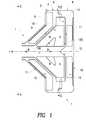
- FIG. 3Ais a cross-sectional view of an impeller blade taken generally along the line A-A of FIG. 2 ;
- FIG. 3Bis an enlargement of the blade-pump housing interface portion of FIG. 3A ;
- FIG. 3Cis all alternative impeller blade shape
- FIGS. 4A , B, Cillustrate various possible locations of magnet material within a blade
- FIGS. 5A , B and Care left-hand end views of possible winding geometries taken generally along the line S-S of FIG. 1 ;
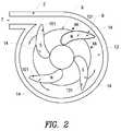
- FIG. 6is a diagrammatic cross-sectional view of an alternative embodiment of the invention as an axial pump
- FIG. 7is an exploded, perspective view of a centrifugal pump assembly according to a further embodiment of the invention.
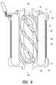
- FIG. 8is a perspective view of the impeller of the assembly of FIG. 7 ;
- FIG. 9is a perspective, cut away view of the impeller of FIG. 8 within the pump assembly of FIG. 7 ;
- FIG. 10is a side section indicative view of the impeller of FIG. 8 ;
- FIG. 11is a detailed view in side section of edge portions of the impeller of FIG. 10 ;
- FIG. 12is a block diagram of an electronic driver circuit for the pump assembly of FIG. 7 ;
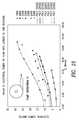
- FIG. 13is a graph of head versus flow for the pump assembly of FIG. 7 ;
- FIG. 14is a graph of pump efficiency versus flow for the pump assembly of FIG. 7 ;
- FIG. 15is a graph of electrical power consumption versus flow for the pump assembly of FIG. 7 ;
- FIG. 16is a plan, section view of the pump assembly showing a volute arrangement according to a preferred embodiment
- FIG. 17is a plan, section view of a pump assembly showing an alternative volute arrangement
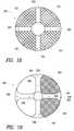
- FIG. 18is a plan view of an impeller according to a further embodiment of the invention.
- FIG. 19is a plan view of an impeller according to a further embodiment of the invention.
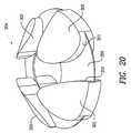
- FIG. 20is a perspective view or an impeller according to a further embodiment of the invention.
- FIG. 21is a perspective view of an impeller according to yet a further embodiment of the invention.
- FIG. 22is a perspective, partially cut away view of an impeller according to yet a further embodiment of the intention.
- FIG. 23is a top, perspective view of the impeller of FIG. 22 ;
- FIG. 24is a perspective view of the impeller of FIG. 22 with its top shroud removed;
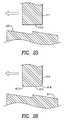
- FIG. 25illustrates an alternative embodiment wherein the deformed surface is located on the pump housing.
- FIG. 26illustrates a further embodiment wherein deformed surfaces are located both on the impeller and on the housing.
- FIG. 27illustrates diagrammatically the basis of operation of the “deformed surfaces” utilised for hydrodynamic suspension of embodiments of the invention.
- the pump assemblies according to various preferred embodiments to be described belowall have particular, although not exclusive, application for implantation in a mammalian body so as to at least assist, if not take over, the function of the mammalian heart. In practice this is performed by placing the pump assembly entirely within the body of the mammal and connecting the pump between the left ventricle and the aorta so as to assist left side heart function. It may also be connected to the right ventricle and pulmonary artery to assist the right side of the heart.
- the pump assemblyincludes an impeller which is fully sealed within the pump body and so does not require a shaft extending through the pump body to support it.
- the impelleris suspended, in use, within the pump body by the operation of hydrodynamic forces imparted as a result of the interaction between the rotating impeller, the internal pump walls and the fluid which the impeller causes to be urged from an inlet of the pump assembly to an outlet thereof.
- a preferred embodiment of the inventionis the centrifugal pump 1 , at depicted in FIGS. 1 and 2 , intended for implantation into a human, in which case the fluid referred to below is blood.
- the pump housing 2can be fabricated in two parts, a front part 3 in the form of a housing body and a back part 4 in the form of a housing cover, with a smooth join therebetween, for example at 5 in FIG. 1 .
- the pump 1has an axial inlet 6 and a tangential outlet 7 .
- the rotating part 100is of very simple form, comprising only blades 8 and a blade support 9 to hold those blades fixed relative to each other. The blades may be curved as depicted in FIG.
- This rotating part 100will hereafter be called the impeller 100 , but it also serves as a bearing component and as the rotor of a motor configuration as to be further described below whereby a torque is applied by electromagnetic means to the impeller 100 .
- the impellerhas no shaft and that the fluid enters the impeller from the region of its axis RR. Some of the fluid passes in front of the support cone 9 and some behind it, so that the pump 1 can be considered of two-sided open type, as compared to conventional open centrifugal pumps, which are only open on the front side.
- Approximate dimensions found adequate for the pump 1 to perform as a ventricular assist device, when operating at speeds in the range 1,500 rpm to 4,000 rpm,are outer blade diameter 40 mm, outer housing average diameter 60 mm, and housing axial length 40 mm.
- the gapsare made small because this leakage flow lowers the pump hydrodynamic efficiency.
- the gapsare made slightly smaller than is conventional in order that the leakage flow can be utilized to create a hydrodynamic bearing.
- the bladesmay also be tapered as depicted in FIGS.
- the thrustis proportional to the square of the blade thickness at the edge, and thus in this embodiment thick blades are favored, since if the proportional of the pump cavity filled by blades is constant, then the net thrust force will be inversely proportional to the number of blades.
- the blade edgescan be made to extend as tails from thin blades as depicted in FIG. 3C in order to increase the blade area adjacent the walls.
- the tailsjoin adjacent blades so as to form a complete shroud with wedges or tapers incorporated therein.
- a shroud designas well as other variations on the blade structure will be described later in this specification.
- the housing front face 10can be made conical, with an angle of around 45° so that it provides both axial and radial hydrodynamic forces. Other angles are suitable that achieve the functional requirements of this pump including the requirements for both axial and radial hydrodynamic forces.
- the housing back face 11can include a roughly conical extension 12 pointing into the pump cavity 106 , to eliminate or minimise the effect of the flow stagnation point oil the axis of the back housing.
- extension 12can resemble an impeller eye to make the flow mixed.
- the housing back face 11is made flat over the bearing surfaces, i.e. under the blade edges. With this the case, a slacker tolerance on the alignment between the axes of the front, part 3 and back part 4 of the housing 2 is permissible.
- An alternativeis to make the back face 11 conical at the bearing surfaces, with taper in the opposite direction to the front face 10 , so that the hydrodynamic forces from the back face will also have radial components. Tighter tolerance on the axes alignment would then be required, and some of the flow would have to undergo a reversal in its axial direction. Again a roughly conical extension (like 12 ) will be needed. There may be some advantage in making the housing surfaces and blade edges non-straight, with varying tangent angle, although this will impose greater manufacturing complexity.
- the amount of material removedsimply varies linearly or approximately linearly across the blade.
- the resulting blade edgesare then planes at a slight inclination to the back face.
- the initial blade edgesare curved and the taper only removes a relatively small amount of material so they still appear curved.
- Alternative taper shapescan include a step in the blade edge, though the corner in that step would represent a stagnation line posing a thrombosis risk.
- the hydrodynamic forceis maximal if the gap at the leading edge is approximately double that at the trailing edge.
- the taperwhich equals the leading edge gap minus the trailing edge gap, should be chosen to match a nominal minimum gap, once the impeller has shifted towards that edge.
- Dimensions which have been found to give adequate thrust forcesare a taper of around 0.05 mm for a nominal minimum gap of around 0.05 mm, and an average circumferential blade edge thickness of around 6 mm for 4 blades.
- the taperis measured within the plane perpendicular to the axis.
- the axial length of the housing between the front and back faces at any positionshould then be made about 0.2 mm greater than the axial length of the blade, when it is coaxial with the housing, so that the minimum gaps are both about 0.1 mm axially when the impeller 100 is centrally positioned within the housing 2 . Then, for example, if the impeller shifts axially by 0.05 mm, the minimum gaps will be 0.05 mm at one face and 0.15 mm at the other face. The thrust increases with decreasing gap and would be much larger from the 0.05 mm gap than from the 0.15 mm gap, about 14 times larger for the above dimensions. Thus there is a net restoring force away from the smaller gap.
- the impellerwill continually shift its position and alignment, varying the gaps in such a way that the total force and torque on the impeller 100 match that, demanded by inertia.
- the gapsare so small, however, that the variation in hydrodynamic efficiency will be small, and the pumping action of the blades will be approximately the same as when the impeller is centrally located.
- a major advantage of the open blades of the present inventionis that a fluid element that does passing through a blade edge gap will have very short residence time in that gap, around 2 ⁇ 10 ⁇ 3 S, and the fluid element will most likely be swept though the pump without passing another blade edge.
- typical working clearances and working movement for the impeller 8 with respect to the upper and lower housing surfaces 10 , 11is of the order of 100 microns clearance at the top and at the bottom.
- gravitational and other forceswill bias the impeller 8 closer to one or other of the housing walls resulting, typically in a clearance at one interface of the order of 50 microns and a corresponding larger clearance at the other interface of the order of 150 microns.
- likely maximum practical clearanceswill range from 300 microns down to 1 micron.
- Typical restoring forces for a 25 gram rotor mass spinning at 2200 rpmare 1.96 Newtons at a 20 micron clearance extending to 0.1 Newtons at an 80 micron clearance.
- the radial force on the impellerdepends critically on the shape of the output flow collector or volute 13 .
- the shapeshould be designed to minimise the radial impeller force over the desired range of pump speeds, without excessively lowering the pump efficiency.
- the optimal shapewill have a roughly helical perimeter between the “cutwater” and outlet.
- the radial forcecan also be reduced by the introduction of an internal division in the volute 13 to create a second output flow collector passage, with tongue approximately diametrically opposite to the tongue of the first passage.
- FIG. 2An indicative plan view of impeller 100 relative to housing 2 is shown in FIG. 2 having a concentric volute 13 .
- FIG. 17illustrates the alternative volute arrangement comprising a split volute created by volute barrier 107 which causes volute 108 in a first hemisphere of the housing 2 to split into first half volute 109 and second half volute 110 over the second hemisphere.
- the hemispheresare defined respectively on each side of a diameter of the housing 2 which passes through or near exit point 111 of outlet 7 .
- concentric volutescan be utilised, particularly where specific speed is relatively low.
- a vaneless diffusermay also reduce the radial force.
- the blade support cone 9must then be shaped to minimise axial thrust on the impeller and minimise disturbance to the flow over the range of speeds, while maintaining sufficient strength to prevent relative blade movement.
- the key design parameter affecting the axial forceis the angle of the cone.
- the coneis drawn in FIG. 1 as having the same internal diameter as the blades, which may aid manufacture. However, the cone could be made with larger or smaller internal diameter to the blades.
- any bulk hydrodynamic axial force on themcan be balanced by shaping the support cone to produce an opposite bulk hydrodynamic axial force on it.
- the means or providing the driving torque on the impeller 100 of the preferred embodiment of the inventionis to encapsulate permanent magnets 14 in the blades 8 of the impeller 100 and to drive them with a rotating magnetic field pattern from oscillating currents in windings 15 and 16 , fixed relative to the housing 2 .
- Magnets of high remanencesuch as sintered rare-earth magnets should be used to maximise motor efficiency.
- the magnetscan be aligned axially but greater motor efficiency is achieved by tilting the magnetisation direction to an angle of around 15° to 30° outwards from the inlet axis, with 22.5° tilt suitable for a body of conical angle 45°.
- the magnetisation directionmust alternate in polarity for adjacent blades. Thus there must be an even number of blades.
- blade numberis preferred for the bearing force, and since two blades would not have sufficient bearing stiffness to rotation about an axis through the blades and perpendicular to the pump housing (unless the blades are very curved), four blades are recommended. A higher number of blades, for example 6 or 8 will also work.
- FIG. 4Some possible options for locating the magnets 14 within the blades 8 are shown in FIG. 4 .
- the most preferred which is depicted in FIG. 4Ais for the blade to be made of magnet material apart from a biocompatible shell or coating to prevent fluid corroding the magnets and to prevent magnet material (which may be toxic) entering the blood stream.
- the coatingshould also be sufficiently durable especially at blade corners to withstand rubbing during start-up or during inadvertent bearing touch down.
- inside walls of the pump housing 2are also coated with a biologically compatible and wear resistant material such as diamond coating or titanium nitride so that wear on both of the touching surfaces is minimised.
- a biologically compatible and wear resistant materialsuch as diamond coating or titanium nitride
- An acceptable coating thicknessis approximately 1 micron.
- a suitable impeller manufacturing methodis to die-press the entire impeller, blades and support cone, as a single axially aligned magnet.
- the die-pressingis much simplified if near axially uniform blades are used (blades with an overhang such as in FIG. 3C are precluded).
- the crushed rare-earth particlesmust be aligned in an axial magnetic field.
- This method of die-pressing with parallel alignment directionis cheaper for rare-earth magnets, although it produces slightly lower remanence magnets.
- the tolerance in die-pressingis poor, and grinding of the tapered blade edges is required.
- the magnet impellercan be coated, for example by physical vapour deposition, of titanium nitride for example, or by chemical vapour deposition, of a thin diamond coating or a teflon coating.
- the magnet materialcan be potted in titanium or a polymeric housing which is then, in turn, coated with a biologically compatible and tough material such as diamond coating or titanium nitride.
- the impellermust be placed in a special pulse magnetisation fixture, with an individual coil surrounding each blade.
- the support cone of a die-pressed magnet impelleracquires some magnetisation near the blades, with negligible influence.
- FIG. 4B and FIG. 4CAlternative magnet locations are sketched in FIG. 4B and FIG. 4C in which quadrilateral or circular cross-section magnets 14 are inserted into the blades. Sealing and smoothing of the blade edges over the insertion holes is then required to reinstate the taper.
- All edges in the pumpshould be radiused and surfaces smoothed to avoid possible damage to formed elements of the blood.
- the windings 15 and 16 of the preferred embodimentare slotless or air-gap windings with the same pole number as the impeller, namely four poles in the preferred embodiment.
- a ferromagnetic iron yoke 17 of conical form for the front winding and an iron ferromagnetic yoke 18 of annular form for the back windingmay be placed on the outside of the windings to increase the magnetic flux densities and hence increase motor efficiency.
- the winding thicknessesshould be designed for maximum motor efficiency, with the sum of their axial thicknesses somewhat less than but comparable to the magnet axial length.
- the yokescan be made of solid ferromagnetic material such as iron.
- the yokes 17can be laminated, for example in layers or by helically winding thin strip, or can be made of iron/powder epoxy composite.
- the yokesshould be positioned such that there is zero net axial magnetic force on the impeller when it is positioned centrally in the housing.
- the magnetic forceis unstable and increases linearly with axial displacement of the impeller away from the central position, with the gradient being called the negative stiffness of the magnetic force.
- This unstable magnetic forcemust be countered by the hydrodynamic bearings, and so the stiffness should be made as small as possible. Choosing the yoke thickness such that the flux density is at the saturation level reduces the stiffness and gives minimum mass.
- An alternativecan be to have no iron yokes, completely eliminating the unstable axial magnetic force, but the efficiency of such designs may be lower and the magnetic flux density in the immediate vicinity of the pump may violate safety standards and produce some tissue heating.
- the stiffnessis acceptably small for slotless windings with the yokes present.
- Another alternativewould be to insert the windings in slots in laminated iron stators which would increase motor efficiency and enable use of less magnet material and potentially lighter impeller blades.
- the unstable magnetic forceswould be significant for such slotted motors.
- the necessity for fat blades to generate the required bearing forces in this embodimentallows room for large magnets, and so slotless windings are chosen in the preferred embodiment.
- FIG. 5Adepicts the preferred topology for the body winding 15 , viewed from the inlet axis.
- the cover winding 16looks similar but the coils need not avoid the inlet tube and so they appear more triangular in shape.
- the body windinghas a more complex three-dimensional shape with bends at the ends of the body cone section.
- Each windingconsists of three coils.
- Each coilis made from a number of turns of an insulated conductor such as copper with the number of turns chosen to suit the desired voltage.
- the coil side mid-linesspan an angle of about 50°-100° at the axis when the coils are in position.
- the coils for body and coverare aligned axially and the axially adjacent coils are connected in either parallel or series connection to form one phase of the three phase winding.
- Parallel connectionoffers one means of redundancy in that if one coil fails, the phase can still carry current through the other coil.
- each of the coil and body windinghas a neutral point connection as depicted in FIG. 5A , whereas in series connection, only one of the windings has a neutral point.
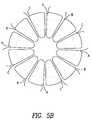
- FIG. 5BAn alternative three phase winding topology, depicted in FIG. 5B , uses four coils per phase for each of the body and cover windings, with each coil wrapping around the yoke, a topology called a “Gramm ring” winding.
- FIG. 5CYet another three phase winding topology, depicted in FIG. 5C , uses two coils per phase for each of the body and cover windings, and connects the coil sides by azimuthal end-windings as is standard motor winding practice.
- the coilsare shown tilted to approximately follow the blade curvature, which can increase motor efficiency, especially for the phase energising strategy to be described below in which only one phase is energised at a time.
- the winding constructioncan be simplified by laying the coils around pins protruding from a temporary former, the pins shown as dots in 2 rings of 6 pins each in FIG. 5C .
- the coilsare labelled alphabetically in the order in which they would be layed, coils a and d for phase A, b and e for phase B, and c and f for phase C.
- the coil locationscould be defined by thin fins, running between the pins in FIG. 5C , along the boundary between the coils.
- the coil connections depicted in FIG. 5Care those appropriate for the winding nearest the motor terminals for the case of series connection, with the optional lead from the neutral point on the other winding included.
- FIGS. 5B and Callow the possibility of higher motor efficiency but only if significantly higher coil mass is allowed, and since option FIG. 5A is more compact and simpler to manufacture, it is the preferred option. Material ribs between the coils of option FIG. 5A can be used to stiffen the housing.
- Multi-stranded flexible conductors within a suitable biocompatible cablecan be used to connect the rotor windings to a motor controller.
- the energisation of the three phasescan be performed by a standard sensorless controller, in which two out of six semiconducting switches in a three phase bridge are turned on at any one time.
- a standard sensorless controllerin which two out of six semiconducting switches in a three phase bridge are turned on at any one time.
- the two housing components 3 and 4are made by injection moulding from non-electrically conducting plastic materials such as Lexan polycarbonate plastic.
- the housing componentscan be made from ceramics.
- the windings and yokesare ideally encapsulated within the housing during fabrication moulding. In this way, the separation between the winding and the magnets is minimised, increasing the motor efficiency, and the housing is thick, increasing its mechanical stiffness.
- the windingscan be positioned outside the housing, of thickness at least around 2 mm for sufficient stiffness.
- the housing material plasticis hygroscopic or if the windings are outside the housing, it may be necessary to first enclose the windings and yoke in a very thin impermeable shell.
- the shellshould be non-conducting (such as ceramic or plastic), but titanium of around 0.1 mm to 0.2 mm thickness would give sufficiently low eddy losses. Encapsulation within such a shell would be needed to prevent winding movement.
- the housing components 3 and 4may be made from a biocompatible metallic material of low electrical conductivity, such as Ti-6A1-4V.
- the materialmust be as thin as possible, e.g. 0.1 mm to 0.5 mm, wherever the material experiences high alternating magnetic flux densities, such as between the coils and the housing inner surfaces 10 and 11 .
- the combining of the motor and bearing components into the impeller in the preferred embodimentprovides several key advantages.
- the rotorconsequently has very simple form, with the only cost of the bearing being tight manufacturing tolerances.
- the rotor massis very low, minimising the bearing force needed to overcome weight. Also, with the bearings and the motor in the same region of the rotor, the bearings forces are smaller than if they had to provide a torque to support magnets at an extremity of the rotor.
- a disadvantage of the combination of functions in the impelleris that its design is a coupled problem.
- the optimisationshould ideally link the fluid dynamics, magnetics and bearing thrust calculations.
- the blade thicknesscan be first roughly sized to give adequate motor efficiency and sufficient bearing forces with a safety-margin.
- both requirementsare met for four blades of approximate average circumferential thickness 6 mm or more.
- the housing, blade, and support cone shapescan then be designed using computational fluid dynamics, maintaining the above minimum average blade thickness.
- the motor statori.e. winding and yoke, can be optimised for maximum motor efficiency.
- FIG. 6depicts an alternative embodiment of the invention as an axial pump.
- the pump housingis made of two parts, a front part 19 and a back part 20 , joined for example at 21 .
- the pumphas an axial inlet 22 and axial outlet 23 .
- the impellercomprises only blades 24 mounted on a support cylinder 25 of reducing radius at each end.
- An important feature of this embodimentis that the blade edges are tapered to generate hydrodynamic thrust forces which suspend the impeller. These forces could be used for radial suspension alone from the straight section 26 of the housing, with some alternative means used for axial suspension, such as stable axial magnetic forces or a conventional tapered-land type hydrodynamic thrust bearing.
- FIG. 6proposes a design which uses the tapered blade edges to also provide an axial hydrodynamic bearing.
- the housingis made with a reducing radius at its ends to form a front face 27 and a back face 28 from which the axial thrusts can suspend the motor axially.
- Magnetsare embedded in the blades with blades having alternating polarity and four blades being recommended. Iron in the outer radius of the support cylinder 25 can be used to increase the magnet flux density. Alternatively, the magnets could be housed in the support cylinder and iron could be used in the blades.
- a slotless helical winding 29is recommended, with outward bending end-windings 30 at one end to enable insertion of the impeller and inward bending windings 31 at the other end to enable insertion of the winding into a cylindrical magnetic yoke 32 .
- the windingcan be encapsulated in the back housing part 20 .
- FIGS. 7 to 15 inclusivethere is shown a further preferred embodiment of the pump assembly 200 .
- the pump assembly 200comprises a housing body 201 adapted for bolted connection to a housing cover 202 and so as to define a centrifugal pump cavity 203 therewithin.
- the cavity 203houses an impeller 204 adapted to receive magnets 205 within cavities 206 defined within blades 207 .
- the blades 207are supported from a support cone 208 .
- a body winding 209symmetrically mounted around inlet 210 and housed between the housing body 201 and a body yoke 211 .
- cover winding 212located within winding cavity 213 which, in turn, is located within housing cover 202 and closed by cover yoke 214 .
- the windings 212 and 209are supplied from the electronic controller of FIG. 12 as for the first embodiment the windings are arranged to receive a three phase electrical supply and so as to set up a rotating magnetic field within cavity 203 which exerts a torque on magnets 205 within the impeller 204 so as to urge the impeller 204 to rotate substantially about central axis TT of cavity 203 and in line with the longitudinal axis of inlet 210 .
- the impeller 204is caused to rotate so as to urge fluid (in this case blood) around volute 215 and through outlet 216 .
- the assemblyis bolted together in the manner indicated by screws 217 .
- the yokes 211 , 214are held in place by fasteners 218 .
- press fittingis possible provided sufficient integrity of seal can be maintained.
- FIG. 8shows the impeller 204 of this embodiment and clearly shows the support cone 208 from which the blades 207 extend.
- the axial cavity 219which is arranged, in use, to be aligned with the longitudinal axis of inlet 210 and through which blood is received for urging by blades 207 is clearly visible.
- FIG. 9shows the axial cavity 219 and also the magnet cavities 206 located within each blade 207 .
- the preferred cone structure 220 extending from housing cover 202 aligned with the axis of inlet 210 and axial cavity 219 of impeller 204is also shown.
- FIG. 10is a side section, indicative view of the impeller 204 defining the orientations of central axis FF, top taper edge DD and bottom taper edge BB, which tapers are illustrated in FIG. 11 in side section view.
- FIG. 11Ais a section of a blade 207 of impeller 204 taken through plane DD as defined in FIG. 10 and shows the top edge 221 to be profiled from a leading edge 223 to a trailing edge 224 as follows; central portion 227 comprises an ellipse with centre on the dashed midline having a semi-major axis of radius 113 mm and a semi-minor axis of radius 80 mm and then followed by leading conical surface 225 and trailing conical surface 226 on either side thereof as illustrated in FIG. 11A .
- the leading surface 225has radius 0.05 mm less than the trailing surface 226 .
- This prescriptionis for a taper which can be achieved by a grinding wheel, but many alternative prescriptions could be devised to give a taper of similar utility.
- the leading edge 223is radiused as illustrated.
- FIG. 11Billustrates in cross-section the bottom edge 222 of blade 207 cut along plane BB of FIG. 10 .
- the bottom edgeincludes cap 228 utilised for sealing magnet 205 within cavity 206 .
- substantially the entire edgecomprises a straight taper with a radius of 0.05 mm at leading edge 229 and a radius of 0.25 mm at trailing edge 230 .
- the blade 207is 6.0 mm in width excluding the radii at either end.
- FIG. 12comprises a block diagram of the electrical controller suitable for driving the pump assembly 200 and comprises a three phase commutation controller 232 adapted to drive the windings 209 , 212 of the pump assembly.
- the commutation controller 232determines relative phase and frequency values for driving the windings with reference to set point speed input 233 derived from physiological controller 234 which, in turn, receives control inputs 235 comprising motor current input and motor speed (derived from the commutation controller 232 ), patient blood flow 236 , and venous oxygen saturation 237 .
- the pump blood flowcan be approximately inferred from the motor speed and current via curve-fitted formulae.
- FIG. 13is a graph of pressure against flow for the pump assembly 200 where the fluid pumped is 18% glycerol for impeller rotation velocity over the range 1500 RPM to 2500 RPM.
- the 18% glycerol liquidis believed to be a good analogue for blood under certain circumstances, for example in the housing gap.
- FIG. 14graphs pump efficiency against flow for the same fluid over the same speed ranges as for FIG. 13 .
- FIG. 15is a graph of electrical power consumption against flow for the same fluid over the same speed ranges as for FIG. 13 .
- the common theme running through the first, second and third embodiments described thus faris the inclusion in the impeller of a taper or other deformed surface which, in use, moves relative to the adjacent housing wall thereby to cause a restriction with respect to the line of movement of the taper or deformity thereby to generate thrust upon the impeller which includes a component substantially normal to the line of movement of the surface and also normal to the adjacent internal pump wall with respect to which the restriction is defined for fluid located therebetween.
- At least one set of surfacesmust be angled with respect to the longitudinal axis of the impeller (preferably at approximately 45° thereto) thereby to generate or resolve opposed radial forces and an axial force which can be balanced by a corresponding axial force generated by at least one other tapered or deformed surface located elsewhere on the impeller.
- top surfaces of the blades 8 , 207are angled at approximately 45° with respect to the longitudinal axis of the impeller 100 , 204 and arranged for rotation with respect to the internal walls of a similarly angled conical pump housing.
- the top surfaces of the bladesare deformed so as to create the necessary restriction in the gap between the top surfaces of the blades and the internal walls of the conical pump housing thereby to generate a thrust which can be resolved to both radial and axial components.
- the bottom faces of the blades 8 , 207comprise surfaces substantially lying in a plane at right angles to the axis of rotation of the impeller and, with their deformities define a gap with respect to a lower inside face of the pump housing against which a substantially only axial thrust is generated.
- Such arrangementscan include a double cone arrangement where the conical top surface of the blades is mirrored in a corresponding bottom conical surface.
- the only concern with this arrangementis the increased depth of pump which can be a problem for in vivo applications where size minimisation is an important criteria.
- FIG. 18a further embodiment of the invention is illustrated comprising a plan view of the impeller 300 forming part of a “channel” pump.
- the blades 301have been widened relative to the blades 207 of the third embodiment to the point where they are almost sector-shaped and the flow gaps between adjacent blades 301 , as a result, take the form of a channel 302 , all in communication with axial cavity 303 .
- impeller 304includes sector-shaped blades 305 having curved leading and trailing portions 306 , 307 respectively thereby defining channels 308 having fluted exit portions 309
- the radial and axial hydrodynamic forcesare generated by appropriate profiling of the top and bottom faces of the blades 301 , 305 (not shown in FIGS. 18 and 19 ).
- FIG. 20illustrates a perspective view of an impeller 304 which follows the theme of the impeller arrangement of FIGS. 18 and 19 in perspective view and where like parts are numbered as for FIG. 19 .
- the four blades 305are joined at mid-portions thereof by a blade support in the form of a conical rim 350 and have edge portions which are shaped so as to have an increased curvature on the trailing edge 351 thereof compared with the leading edge 352 .
- a fifth embodiment of a pump assembly according to the inventioncomprises an impeller 410 as illustrated in FIG. 21 where, conceptually, the upper and lower surfaces of the blades of previous embodiments are interconnected by a top shroud 411 and a bottom shroud 412 .
- the blades 413can be reduced to a very small width as the hydrodynamic behaviour imparted by their surfaces in previous embodiments is now given effect by the profiling of the shrouds 411 , 412 which, in this instance, comprises a series of smooth-edged wedges with the leading surface of one wedge directly interconnected to the trailing edge of the next leading wedge 414 .
- top shroud 411is of overall conical shape thereby to impart both radial and axial thrust forces whilst the bottom shroud 412 is substantially planar thereby to impart substantially only axial thrust forces.
- FIG. 21shows the surfaces of the shroud 411 angled at approximately 45° to the vertical, other inclinations are possible extending to an inclination of 0° to the vertical which is to say the impeller 410 can take the form of a cylinder with surface rippling or other deformations which impart the necessary hydrodynamic lift, in use.
- FIGS. 22 to 24a specific example of the concept embodied in FIG. 21 is illustrated and wherein like components are numbered as for FIG. 21 .
- the blades 413are thin compared to previous embodiments and, in this instance, are arcuate channels 416 therebetween which allow fluid communication from a centre volume 417 to the periphery 418 of the impeller 410 .
- the wedges 419are separated one from the other on each shroud by channels 419 .
- the channelsextend radially down the shroud from the centre volume 417 to the periphery 418 .
- the magnets required for the driving torquecan be contained within the top or bottom volute or both, along with the optional soft magnetic yokes to increase rotor efficiency.
- a variation of this embodimentis to have the wedge profiling cut into the inter surfaces of the housing and have smooth shroud surfaces.
- FIG. 25In contrast to the embodiments illustrated with respect to FIGS. 3A , 3 B and 3 C an arrangement is shown in FIG. 25 wherein the “deformed surface” comprises a stepped formation 510 forming part of an inner wall of the pump housing (not shown).
- the rotor including blade 511includes a flat working surface 512 (and not having a deformed surface therein) which is adapted for relative movement in the direction of the arrow shown with respect to the stepped formation 510 thereby to generate hydrodynamic thrust therebetween.
- FIG. 26there is shown an arrangement of rotor blade 610 with respect to stepped formation 611 and wherein the rotor blade 610 includes a deformed surface 612 at a working face thereof.
- the deformationcomprises curved edges 613 , 614 .
- relative movement of the rotor blade 610 in the direction of the arrow with respect to deformed surface 611 forming part of the pump housing (not shown)causes relative hydrodynamic thrust therebetween.
- this specificationdescribes the suspension of an impeller 600 within a pump housing 601 by the use of hydrodynamic forces.
- the suspension of the impeller 600is performed dominantly which is to say exclusively by hydrodynamic forces.
- the hydrodynamic forcesare forces which are created by relative movement between two surfaces which have a fluid in the gap between the two surfaces.
- the fluidis blood.
- hydrodynamic forcescan arise during relative movement between two surfaces even where those surfaces are substantially entirely parallel to each other or non-deformed. However, in this specification, hydrodynamic forces are caused to arise during relative movement between two surfaces where at least one of the surfaces includes a “deformed surface”.
- deformed surfacemeans a surface which includes an irregularity relative to a surface which it faces such that, when the surface moves in a predetermined direction relative to the surface which it faces the fluid located in the gap there between experiences a change in relative distance between the surfaces along the line of movement thereby to cause a hydrodynamic force to arise therebetween in the form or a thrust force including at least a component substantially normal to the plane of the gap defined at any given point between the facing surfaces.
- first deformed surface 603forming at least part of a first face 604 of impeller 600 and a second deformed surface 605 on a second face 606 of the impeller 600 .
- the inset of FIG. 27illustrates conceptually how the first deformed surface 603 may form only part of the first face 604 .
- the first deformed surface 603faces first inner surface 607 of the pump housing 601 whilst second deformed surface 605 faces second inner surface 608 of the pump housing 601 .
- first gap 609 defined between first deformed surface 603 and first inner surface 607has a fluid comprising blood located therein whilst second gap 610 defined between second deformed surface 605 and second inner surface 608 also has a fluid comprising blood located therein.
- impeller 600is caused to rotate about impeller axis 611 such that relative movement across first gap 609 between first deformed surface 603 and first inner face 607 occurs and also relative movement across second gap 610 between second deformed surface 605 and second inner surface 608 occurs.
- the orientation of the deformities of first deformed surface 603 and second deformed surface 605 relative to the line of movement of the deformed surfaces 603 , 605 relative to the inner surfaces 607 , 608is such that the fluid in the gaps 609 , 610 experiences a change in height of the gap 609 , 610 as a function of time and with the rate of change dependant on the shape of the deformities of the deformed surfaces and also the rate of rotation of the impeller 600 relative to the housing 601 .
- the height of the gap between the inner surface 607 or 608 and corresponding deformed surface 603 or 605will vary with time due to passage of the deformed surface 603 or 605 over the inner surface.
- Hydrodynamic forces in the form of thrust forces normal to the line of relative movement of the respective deformed surfaces 603 , 605 relative to the inner surfaces 607 , 608thus arise.
- first gap 609lips substantially in a single plane whilst the second gap 610 is in the form of a cone and angled at an acute angle relative to the plane of the first gap 609 .
- first gap 609 and second gap 610are substantially normal to and distributed across both the predominantly flat plane of first deformed surface 603 and normal to the substantially conical surface of second deformed surface 605 thereby permitting restoring forces to be applied between the impeller 600 and the pump housing 601 thereby to resist forces which seek to translate the impeller 600 in space relative to the pump housing 601 and also to rotate the impeller 600 about any axis (other than about the impeller axis 611 ) relative to the pump housing 601 .
- This arrangementsubstantially resists five degrees of freedom of movement of impeller 600 with respect to the housing 601 and does so predominantly without any external intervention to control the position of the impeller with respect to the housing given that disturbing forces from other sources, most notably magnetic forces on the impeller due to its use as rotor of the motor are net zero when the impeller occupies a suitable equilibrium position.
- the balance of all forces on the rotor, effected by manipulation of magnetic and other external sources,may be adjusted such that the rotor is predominantly hydrodynamically born.
- the pump assembly 1 , 200is applicable to pump fluids such as blood on a continuous basis. With its expected reliability it is particularly applicable as an in vivo heart assist pump.
- the pump assemblycan also be used with advantage for the pumping of other fluids where damage to the fluid due to high shear stresses must be avoided or where leakage of the fluid must be prevented with a very high degree of reliability—for example where the fluid is a dangerous fluid.
Landscapes
- Engineering & Computer Science (AREA)
- Health & Medical Sciences (AREA)
- Heart & Thoracic Surgery (AREA)
- Mechanical Engineering (AREA)
- Cardiology (AREA)
- General Engineering & Computer Science (AREA)
- Anesthesiology (AREA)
- Biomedical Technology (AREA)
- Hematology (AREA)
- Life Sciences & Earth Sciences (AREA)
- Animal Behavior & Ethology (AREA)
- General Health & Medical Sciences (AREA)
- Public Health (AREA)
- Veterinary Medicine (AREA)
- Fluid Mechanics (AREA)
- Physics & Mathematics (AREA)
- External Artificial Organs (AREA)
- Structures Of Non-Positive Displacement Pumps (AREA)
Abstract
Description
- 1. Low haemolysis, hence low running speed and controlled fluid dynamics (especially shear stress) in the gap between the casing and impeller. This in turn led to the selection of radial off-flow and minimal incidence at on-flow to the rotor;
- 2. Radial or near-radial off-flow from the impeller can be chosen in order to yield a “flat” pump characteristic (HQ) curve.
Claims (11)
Priority Applications (3)
| Application Number | Priority Date | Filing Date | Title |
|---|---|---|---|
| US12/347,263US8002518B2 (en) | 1997-09-05 | 2008-12-31 | Rotary pump with hydrodynamically suspended impeller |
| US13/181,452US8366381B2 (en) | 1997-09-05 | 2011-07-12 | Rotary pump with hydrodynamically suspended impeller |
| US13/758,887US20130225910A1 (en) | 1997-09-05 | 2013-02-04 | Rotary Pump with Hydrodynamically Suspended Impeller |
Applications Claiming Priority (9)
| Application Number | Priority Date | Filing Date | Title |
|---|---|---|---|
| AUPO9027AAUPO902797A0 (en) | 1997-09-05 | 1997-09-05 | A rotary blood pump with hydrodynamically suspended impeller |
| AUPO9027 | 1997-09-05 | ||
| PCT/AU1998/000725WO1999012587A1 (en) | 1997-09-05 | 1998-09-07 | A rotary pump with hydrodynamically suspended impeller |
| US09/281,608US6227797B1 (en) | 1997-09-05 | 1999-03-30 | Rotary pump with hydrodynamically suspended impeller |
| US09/299,038US6250880B1 (en) | 1997-09-05 | 1999-04-23 | Rotary pump with exclusively hydrodynamically suspended impeller |
| US09/893,319US6638011B2 (en) | 1997-09-05 | 2001-06-26 | Rotary pump with exclusively hydrodynamically suspended impeller |
| US10/634,211US6966748B2 (en) | 1997-09-05 | 2003-08-05 | Rotary pump with exclusively hydrodynamically suspended impeller |
| US11/212,227US7476077B2 (en) | 1997-09-05 | 2005-08-26 | Rotary pump with exclusively hydrodynamically suspended impeller |
| US12/347,263US8002518B2 (en) | 1997-09-05 | 2008-12-31 | Rotary pump with hydrodynamically suspended impeller |
Related Parent Applications (1)
| Application Number | Title | Priority Date | Filing Date |
|---|---|---|---|
| US11/212,227ContinuationUS7476077B2 (en) | 1997-09-05 | 2005-08-26 | Rotary pump with exclusively hydrodynamically suspended impeller |
Related Child Applications (1)
| Application Number | Title | Priority Date | Filing Date |
|---|---|---|---|
| US13/181,452ContinuationUS8366381B2 (en) | 1997-09-05 | 2011-07-12 | Rotary pump with hydrodynamically suspended impeller |
Publications (2)
| Publication Number | Publication Date |
|---|---|
| US20090155049A1 US20090155049A1 (en) | 2009-06-18 |
| US8002518B2true US8002518B2 (en) | 2011-08-23 |
Family
ID=3803312
Family Applications (7)
| Application Number | Title | Priority Date | Filing Date |
|---|---|---|---|
| US09/281,608Expired - LifetimeUS6227797B1 (en) | 1997-05-09 | 1999-03-30 | Rotary pump with hydrodynamically suspended impeller |
| US09/734,532Expired - LifetimeUS6609883B2 (en) | 1997-05-09 | 2000-12-11 | Rotary pump with hydrodynamically suspended impeller |
| US10/634,538Expired - LifetimeUS7156802B2 (en) | 1997-09-05 | 2003-08-05 | Rotary pump with hydrodynamically suspended impeller |
| US11/238,400AbandonedUS20060030748A1 (en) | 1997-09-05 | 2005-09-29 | Rotary pump with hydrodynamically suspended impeller |
| US12/347,263Expired - Fee RelatedUS8002518B2 (en) | 1997-09-05 | 2008-12-31 | Rotary pump with hydrodynamically suspended impeller |
| US13/181,452Expired - Fee RelatedUS8366381B2 (en) | 1997-09-05 | 2011-07-12 | Rotary pump with hydrodynamically suspended impeller |
| US13/758,887AbandonedUS20130225910A1 (en) | 1997-09-05 | 2013-02-04 | Rotary Pump with Hydrodynamically Suspended Impeller |
Family Applications Before (4)
| Application Number | Title | Priority Date | Filing Date |
|---|---|---|---|
| US09/281,608Expired - LifetimeUS6227797B1 (en) | 1997-05-09 | 1999-03-30 | Rotary pump with hydrodynamically suspended impeller |
| US09/734,532Expired - LifetimeUS6609883B2 (en) | 1997-05-09 | 2000-12-11 | Rotary pump with hydrodynamically suspended impeller |
| US10/634,538Expired - LifetimeUS7156802B2 (en) | 1997-09-05 | 2003-08-05 | Rotary pump with hydrodynamically suspended impeller |
| US11/238,400AbandonedUS20060030748A1 (en) | 1997-09-05 | 2005-09-29 | Rotary pump with hydrodynamically suspended impeller |
Family Applications After (2)
| Application Number | Title | Priority Date | Filing Date |
|---|---|---|---|
| US13/181,452Expired - Fee RelatedUS8366381B2 (en) | 1997-09-05 | 2011-07-12 | Rotary pump with hydrodynamically suspended impeller |
| US13/758,887AbandonedUS20130225910A1 (en) | 1997-09-05 | 2013-02-04 | Rotary Pump with Hydrodynamically Suspended Impeller |
Country Status (8)
| Country | Link |
|---|---|
| US (7) | US6227797B1 (en) |
| EP (1) | EP1019116B1 (en) |
| JP (1) | JP3725027B2 (en) |
| CN (1) | CN1278188A (en) |
| AT (1) | ATE292987T1 (en) |
| AU (1) | AUPO902797A0 (en) |
| DE (1) | DE69829766T2 (en) |
| WO (1) | WO1999012587A1 (en) |
Cited By (18)
| Publication number | Priority date | Publication date | Assignee | Title |
|---|---|---|---|---|
| US8864643B2 (en) | 2011-10-13 | 2014-10-21 | Thoratec Corporation | Pump and method for mixed flow blood pumping |
| US8894561B2 (en) | 2012-03-05 | 2014-11-25 | Thoratec Corporation | Modular implantable medical pump |
| US9144638B2 (en) | 2013-03-14 | 2015-09-29 | Thoratec Corporation | Blood pump rotor bearings |
| US9217435B2 (en) | 2012-10-23 | 2015-12-22 | Nidec Motor Corporation | Axial flow pump with integrated motor |
| US9265870B2 (en) | 2010-10-13 | 2016-02-23 | Thoratec Corporation | Pumping blood |
| US9827357B2 (en) | 2011-12-03 | 2017-11-28 | Indiana University Research And Technology Corporation | Cavopulmonary viscous impeller assist device and method |
| US10660998B2 (en) | 2016-08-12 | 2020-05-26 | Tci Llc | Devices and methods for monitoring bearing and seal performance |
| US10724534B2 (en) | 2014-11-26 | 2020-07-28 | Tc1 Llc | Pump and method for mixed flow blood pumping |
| US10857273B2 (en) | 2016-07-21 | 2020-12-08 | Tc1 Llc | Rotary seal for cantilevered rotor pump and methods for axial flow blood pumping |
| US11471664B2 (en)* | 2017-08-29 | 2022-10-18 | Rocketheart Technology Co. Ltd | Blood pump device |
| US11583672B2 (en)* | 2019-08-30 | 2023-02-21 | Boston Scientific Scimed, Inc. | Glass impeller for a blood pump |
| US11712501B2 (en) | 2019-11-12 | 2023-08-01 | Fresenius Medical Care Deutschland Gmbh | Blood treatment systems |
| US11730871B2 (en) | 2019-11-12 | 2023-08-22 | Fresenius Medical Care Deutschland Gmbh | Blood treatment systems |
| US11752247B2 (en) | 2019-11-12 | 2023-09-12 | Fresenius Medical Care Deutschland Gmbh | Blood treatment systems |
| US11925736B2 (en) | 2019-11-12 | 2024-03-12 | Fresenius Medical Care Deutschland Gmbh | Blood treatment systems |
| TWI879673B (en)* | 2019-06-28 | 2025-04-01 | 美商阿比奥梅德公司 | Intravascular blood pump having multiplayer coreless coils, slotless permanent magnet electric motor, and method of forming stator for use in slotless permanent magnet motor |
| US12285553B2 (en) | 2019-11-12 | 2025-04-29 | Fresenius Medical Care Deutschland Gmbh | Blood treatment systems |
| US12329890B2 (en) | 2019-11-12 | 2025-06-17 | Fresenius Medical Care Deutschland Gmbh | Blood treatment systems |
Families Citing this family (208)
| Publication number | Priority date | Publication date | Assignee | Title |
|---|---|---|---|---|
| US5840070A (en)* | 1996-02-20 | 1998-11-24 | Kriton Medical, Inc. | Sealless rotary blood pump |
| AUPO902797A0 (en) | 1997-09-05 | 1997-10-02 | Cortronix Pty Ltd | A rotary blood pump with hydrodynamically suspended impeller |
| US6250880B1 (en) | 1997-09-05 | 2001-06-26 | Ventrassist Pty. Ltd | Rotary pump with exclusively hydrodynamically suspended impeller |
| US6889082B2 (en) | 1997-10-09 | 2005-05-03 | Orqis Medical Corporation | Implantable heart assist system and method of applying same |
| DE29821565U1 (en)* | 1998-12-02 | 2000-06-15 | Impella Cardiotechnik AG, 52074 Aachen | Bearingless blood pump |
| CA2370755C (en)* | 1999-04-23 | 2009-11-24 | Peter Joseph Ayre | A rotary blood pump and control system therefor |
| AUPP995999A0 (en) | 1999-04-23 | 1999-05-20 | University Of Technology, Sydney | Non-contact estimation and control system |
| AU2003201358C1 (en)* | 1999-04-23 | 2003-06-12 | Thoratec Corporation | A Rotary Blood Pump and Control System Therefor |
| AU760610C (en)* | 1999-04-23 | 2004-03-11 | Thoratec Corporation | A rotary blood pump and control system therefor |
| US20050196293A1 (en)* | 1999-04-23 | 2005-09-08 | Ayre Peter J. | Rotary blood pump and control system therefor |
| US6234772B1 (en) | 1999-04-28 | 2001-05-22 | Kriton Medical, Inc. | Rotary blood pump |
| AT412065B (en) | 2000-03-24 | 2004-09-27 | Schima Heinrich Dr | ROTATIONAL PUMP WITH HYDRAULICALLY BEARED ROTOR |
| US6761532B2 (en)* | 2001-03-14 | 2004-07-13 | Vascor, Inc. | Touch down of blood pump impellers |
| AUPR514201A0 (en) | 2001-05-21 | 2001-06-14 | Ventrassist Pty Ltd | Staged implantation of ventricular assist devices |
| EP1284369A1 (en)* | 2001-08-16 | 2003-02-19 | Levitronix LLC | Method for delivering variable amounts of flow, and dosing pumping using this method |
| US6641378B2 (en) | 2001-11-13 | 2003-11-04 | William D. Davis | Pump with electrodynamically supported impeller |
| DE10201405A1 (en)* | 2002-01-15 | 2003-07-24 | Siemens Ag | Pump for pumping fuel has a pump casing with a pumping chamber fitted with inlets and outlets as well as a pumping wheel in the chamber fastened on a drive shaft rotating on bearings in the casing. |
| CA2374989A1 (en)* | 2002-03-08 | 2003-09-08 | Andre Garon | Ventricular assist device comprising a dual inlet hybrid flow blood pump |
| US6881033B2 (en)* | 2002-09-30 | 2005-04-19 | Fisher & Paykel Healthcare Limited | Impeller |
| US7066189B2 (en)* | 2002-12-20 | 2006-06-27 | Control Components, Inc. | Predictive maintenance and initialization system for a digital servovalve |
| WO2004106746A1 (en) | 2003-05-15 | 2004-12-09 | William Davis | Pump with magnetic bearings |
| AU2003903138A0 (en)* | 2003-06-20 | 2003-07-03 | Resmed Limited | Method and apparatus for improving the comfort of cpap |
| DE10330434A1 (en) | 2003-07-04 | 2005-02-03 | Jostra Ag | Centrifugal pump |
| AU2003904032A0 (en)* | 2003-08-04 | 2003-08-14 | Ventracor Limited | Improved Transcutaneous Power and Data Transceiver System |
| US7416525B2 (en) | 2003-09-18 | 2008-08-26 | Myrakelle, Llc | Rotary blood pump |
| US7070398B2 (en)* | 2003-09-25 | 2006-07-04 | Medforte Research Foundation | Axial-flow blood pump with magnetically suspended, radially and axially stabilized impeller |
| US7229258B2 (en)* | 2003-09-25 | 2007-06-12 | Medforte Research Foundation | Streamlined unobstructed one-pass axial-flow pump |
| EP1670524A4 (en)* | 2003-10-09 | 2012-12-26 | Thoratec Corp | Impeller |
| JP4767488B2 (en) | 2003-10-23 | 2011-09-07 | Ntn株式会社 | Magnetic levitation pump |
| EP1677857A1 (en)* | 2003-10-31 | 2006-07-12 | Ventracor Limited | Improved blood pump comprising polymeric components |
| DE602004005297T2 (en)* | 2004-01-26 | 2007-12-20 | Nidec Shibaura Corp., Obama | Centrifugal pump for washing machines |
| WO2005093257A1 (en)* | 2004-03-05 | 2005-10-06 | Waters Investments Limited | Device and methods of measuring pressure |
| AU157255S (en) | 2004-03-10 | 2005-01-12 | Thoratec Corp | Impeller |
| DE102004019721A1 (en)* | 2004-03-18 | 2005-10-06 | Medos Medizintechnik Ag | pump |
| DE102004022141A1 (en)* | 2004-05-05 | 2005-11-24 | Heidelberger Druckmaschinen Ag | Device for conveying and simultaneously aligning sheets |
| EP2151257B1 (en) | 2004-08-13 | 2013-04-17 | Delgado, Reynolds M., III | Apparatus for long-term assisting a left ventricle to pump blood |
| CN1596999B (en)* | 2004-08-20 | 2010-04-28 | 清华大学 | Spiral Wing Type Micro Blood Pump |
| USD514125S1 (en) | 2004-09-03 | 2006-01-31 | Ventracor Limited | Impeller |
| US7393181B2 (en) | 2004-09-17 | 2008-07-01 | The Penn State Research Foundation | Expandable impeller pump |
| AU2004220728B2 (en)* | 2004-10-14 | 2010-06-24 | Thoratec Corporation | Improvements in Rotor Stability of a Rotary Pump |
| US20060083642A1 (en)* | 2004-10-18 | 2006-04-20 | Cook Martin C | Rotor stability of a rotary pump |
| US7699586B2 (en)* | 2004-12-03 | 2010-04-20 | Heartware, Inc. | Wide blade, axial flow pump |
| US8419609B2 (en) | 2005-10-05 | 2013-04-16 | Heartware Inc. | Impeller for a rotary ventricular assist device |
| US7972122B2 (en)* | 2005-04-29 | 2011-07-05 | Heartware, Inc. | Multiple rotor, wide blade, axial flow pump |
| US8152035B2 (en)* | 2005-07-12 | 2012-04-10 | Thoratec Corporation | Restraining device for a percutaneous lead assembly |
| US20070052389A1 (en)* | 2005-07-19 | 2007-03-08 | Michiel Kooij | Battery receptacle |
| US20070054256A1 (en)* | 2005-09-06 | 2007-03-08 | Jeremy Low | Mock circulatory apparatus |
| CN100363632C (en)* | 2005-09-16 | 2008-01-23 | 清华大学 | A shaftless open impeller suitable for micropumps |
| DE102005045597B4 (en)* | 2005-09-23 | 2017-05-18 | Siemens Healthcare Gmbh | In the human or animal body implantable pumping device and pumping device comprising such a pumping device |
| AU2013205145B2 (en)* | 2005-10-05 | 2013-08-15 | Heartware, Inc. | Axial flow pump with multi-grooved rotor |
| WO2007040663A1 (en)* | 2005-10-05 | 2007-04-12 | Heartware, Inc. | Axial flow pump with multi-grooved rotor |
| US20070142923A1 (en)* | 2005-11-04 | 2007-06-21 | Ayre Peter J | Control systems for rotary blood pumps |
| US20070142696A1 (en)* | 2005-12-08 | 2007-06-21 | Ventrassist Pty Ltd | Implantable medical devices |
| EP1977110B8 (en) | 2006-01-13 | 2018-12-26 | HeartWare, Inc. | Rotary blood pump |
| US8672611B2 (en) | 2006-01-13 | 2014-03-18 | Heartware, Inc. | Stabilizing drive for contactless rotary blood pump impeller |
| US20070177995A1 (en)* | 2006-02-01 | 2007-08-02 | Yoshio Yano | Pump device |
| US20070183908A1 (en)* | 2006-02-06 | 2007-08-09 | Yoshio Yano | Contactless centrifugal pump |
| CN102380135A (en) | 2006-03-23 | 2012-03-21 | 宾州研究基金会 | Heart assist device with expandable impeller pump |
| AU2007201127B2 (en)* | 2006-03-23 | 2012-02-09 | Thoratec Corporation | System For Preventing Diastolic Heart Failure |
| KR20090074110A (en) | 2006-03-31 | 2009-07-06 | 오퀴스 메디컬 코포레이션 | Rotary Blood Pump |
| EP1847281A1 (en) | 2006-04-20 | 2007-10-24 | Ventrassist Pty Ltd | System and method of controlling a rotary blood pump |
| US20070247968A1 (en)* | 2006-04-21 | 2007-10-25 | V & P Scientific, Inc. | Sandwich magnetic stir elements for stirring the contents of vessels |
| US7850594B2 (en)* | 2006-05-09 | 2010-12-14 | Thoratec Corporation | Pulsatile control system for a rotary blood pump |
| US7963905B2 (en) | 2006-10-11 | 2011-06-21 | Thoratec Corporation | Control system for a blood pump |
| US20080133006A1 (en)* | 2006-10-27 | 2008-06-05 | Ventrassist Pty Ltd | Blood Pump With An Ultrasonic Transducer |
| US20080200750A1 (en)* | 2006-11-17 | 2008-08-21 | Natalie James | Polymer encapsulation for medical device |
| US7762941B2 (en)* | 2007-04-25 | 2010-07-27 | Robert Jarvik | Blood pump bearings with separated contact surfaces |
| US8152493B2 (en)* | 2007-04-30 | 2012-04-10 | Hearthware Inc. | Centrifugal rotary blood pump with impeller having a hydrodynamic thrust bearing surface |
| JP5266464B2 (en)* | 2007-05-10 | 2013-08-21 | ライニッシュ−ヴェストフェリッシェ・テクニッシェ・ホッホシューレ・アーヘン | Cardiac function change evaluation device |
| CN101715352B (en) | 2007-06-14 | 2013-11-06 | 卡龙心脏科技有限公司 | Reduced diameter axial rotary pump for cardiac assist |
| TWI331272B (en)* | 2007-06-29 | 2010-10-01 | Inventec Corp | Heat dissipation module |
| WO2009099644A1 (en) | 2008-02-08 | 2009-08-13 | Heartware, Inc. | Ventricular assist device for intraventricular placement |
| JP5171953B2 (en) | 2008-06-23 | 2013-03-27 | テルモ株式会社 | Blood pump device |
| EP2372160B1 (en) | 2008-12-08 | 2014-07-30 | Thoratec Corporation | Centrifugal pump device |
| JP5378010B2 (en) | 2009-03-05 | 2013-12-25 | ソラテック コーポレーション | Centrifugal pump device |
| CN102341600B (en) | 2009-03-06 | 2014-12-10 | 胸腔科技有限公司 | Centrifugal pump device |
| WO2010118476A1 (en) | 2009-04-16 | 2010-10-21 | Bivacor Pty Ltd | Heart pump controller |
| US8167593B2 (en)* | 2009-04-16 | 2012-05-01 | The Board Of Regents Of The University Of Texas System | System and method for pump with deformable bearing surface |
| EP2419159A4 (en) | 2009-04-16 | 2017-07-19 | Bivacor Pty Ltd | Heart pump controller |
| US9782527B2 (en)* | 2009-05-27 | 2017-10-10 | Tc1 Llc | Monitoring of redundant conductors |
| CN101810891B (en)* | 2009-06-08 | 2012-10-24 | 钱逸 | Self-suspending artificial heart |
| CN102481398A (en) | 2009-07-01 | 2012-05-30 | 宾夕法尼亚州研究基金会 | Blood pump with expandable cannula |
| EP2273124B1 (en)* | 2009-07-06 | 2015-02-25 | Levitronix GmbH | Centrifugal pump and method for compensating for the axial impulse in a centrifugal pump |
| US8821365B2 (en) | 2009-07-29 | 2014-09-02 | Thoratec Corporation | Rotation drive device and centrifugal pump apparatus using the same |
| US8690749B1 (en) | 2009-11-02 | 2014-04-08 | Anthony Nunez | Wireless compressible heart pump |
| CN101732769B (en)* | 2010-01-26 | 2011-10-05 | 浙江大学 | Implantable blood pump with passive suspension bearing |
| EP2532897A4 (en) | 2010-02-02 | 2015-05-27 | Mitsubishi Heavy Ind Ltd | Centrifugal pump |
| JP5443197B2 (en) | 2010-02-16 | 2014-03-19 | ソラテック コーポレーション | Centrifugal pump device |
| US9662431B2 (en) | 2010-02-17 | 2017-05-30 | Flow Forward Medical, Inc. | Blood pump systems and methods |
| US9555174B2 (en) | 2010-02-17 | 2017-01-31 | Flow Forward Medical, Inc. | Blood pump systems and methods |
| KR101845213B1 (en) | 2010-02-17 | 2018-05-18 | 플로우 포워드 메디컬, 인크. | System and method to increase the overall diameter of veins |
| JP5572832B2 (en) | 2010-03-26 | 2014-08-20 | ソーラテック コーポレイション | Centrifugal blood pump device |
| EP2582414B1 (en)* | 2010-06-18 | 2021-08-04 | Heartware, Inc. | Rotor for a blood pump with hydrodynamic chamfer thrust bearings |
| JP5898190B2 (en) | 2010-06-22 | 2016-04-06 | ソラテック コーポレーション | Fluid delivery system and method for monitoring a fluid delivery system |
| CA2802215A1 (en) | 2010-06-22 | 2011-12-29 | Thoratec Corporation | Apparatus and method for modifying pressure-flow characteristics of a pump |
| JP5681403B2 (en) | 2010-07-12 | 2015-03-11 | ソーラテック コーポレイション | Centrifugal pump device |
| EP2605809B1 (en) | 2010-08-20 | 2017-10-11 | Tc1 Llc | Implantable blood pump |
| WO2012024567A1 (en) | 2010-08-20 | 2012-02-23 | Thoratec Corporation | Assembly and method for stabilizing a percutaneous cable |
| JP5577506B2 (en) | 2010-09-14 | 2014-08-27 | ソーラテック コーポレイション | Centrifugal pump device |
| US9227001B2 (en) | 2010-10-07 | 2016-01-05 | Everheart Systems Inc. | High efficiency blood pump |
| US8551163B2 (en) | 2010-10-07 | 2013-10-08 | Everheart Systems Inc. | Cardiac support systems and methods for chronic use |
| US8435016B2 (en)* | 2010-11-10 | 2013-05-07 | Hamilton Sundstrand Corporation | Vertical shaft pumping system with lubricant impeller arrangement |
| US9496924B2 (en) | 2010-12-10 | 2016-11-15 | Everheart Systems, Inc. | Mobile wireless power system |
| US8597170B2 (en) | 2011-01-05 | 2013-12-03 | Thoratec Corporation | Catheter pump |
| US8485961B2 (en) | 2011-01-05 | 2013-07-16 | Thoratec Corporation | Impeller housing for percutaneous heart pump |
| WO2012094535A2 (en) | 2011-01-06 | 2012-07-12 | Thoratec Corporation | Percutaneous heart pump |
| WO2012094641A2 (en) | 2011-01-06 | 2012-07-12 | Thoratec Corporation | Percutaneous heart pump |
| EP2693609B1 (en) | 2011-03-28 | 2017-05-03 | Thoratec Corporation | Rotation and drive device and centrifugal pump device using same |
| EP2549113B1 (en)* | 2011-07-20 | 2018-10-24 | Levitronix GmbH | Magnetic rotor and rotation pump with a magnetic rotor |
| KR102062132B1 (en) | 2011-08-17 | 2020-01-03 | 플로우 포워드 메디컬, 인크. | Blood pump systems and methods |
| EP2744539B1 (en) | 2011-08-17 | 2022-11-02 | Artio Medical, Inc. | System to increase the overall diameter of a peripheral artery |
| JP6139550B2 (en) | 2011-11-28 | 2017-05-31 | ミ‐ヴァド インコーポレイテッド | Auxiliary circulation apparatus and method |
| JP6083929B2 (en) | 2012-01-18 | 2017-02-22 | ソーラテック コーポレイション | Centrifugal pump device |
| WO2013141120A1 (en) | 2012-03-23 | 2013-09-26 | テルモ株式会社 | Centrifugal pump and method for manufacturing same |
| WO2013145134A1 (en)* | 2012-03-27 | 2013-10-03 | 株式会社サンメディカル技術研究所 | Ventricular assist device pump |
| JP6345113B2 (en)* | 2012-03-27 | 2018-06-20 | 株式会社サンメディカル技術研究所 | Assisted artificial heart system |
| US8721517B2 (en) | 2012-05-14 | 2014-05-13 | Thoratec Corporation | Impeller for catheter pump |
| EP4218887A1 (en) | 2012-05-14 | 2023-08-02 | Tc1 Llc | Mechanical circulatory support device for stabilizing a patient after cardiogenic shock |
| US9327067B2 (en) | 2012-05-14 | 2016-05-03 | Thoratec Corporation | Impeller for catheter pump |
| US9872947B2 (en) | 2012-05-14 | 2018-01-23 | Tc1 Llc | Sheath system for catheter pump |
| US9446179B2 (en) | 2012-05-14 | 2016-09-20 | Thoratec Corporation | Distal bearing support |
| CN102755672A (en)* | 2012-06-21 | 2012-10-31 | 北京工业大学 | Blood pump with high permeability material impeller |
| US9421311B2 (en) | 2012-07-03 | 2016-08-23 | Thoratec Corporation | Motor assembly for catheter pump |
| EP4186557A1 (en) | 2012-07-03 | 2023-05-31 | Tc1 Llc | Motor assembly for catheter pump |
| US9358329B2 (en) | 2012-07-03 | 2016-06-07 | Thoratec Corporation | Catheter pump |
| EP4252823A3 (en)* | 2012-08-15 | 2023-11-15 | Artio Medical, Inc. | Blood pump systems and methods |
| US10258730B2 (en) | 2012-08-17 | 2019-04-16 | Flow Forward Medical, Inc. | Blood pump systems and methods |
| US9579436B2 (en) | 2012-08-31 | 2017-02-28 | Thoratec Corporation | Sensor mounting in an implantable blood pump |
| US9427510B2 (en) | 2012-08-31 | 2016-08-30 | Thoratec Corporation | Start-up algorithm for an implantable blood pump |
| WO2014078506A2 (en)* | 2012-11-14 | 2014-05-22 | Ams Research Corporation | Cell delivery device and system with anti-clumping feature and methods for pelvic tissue treatment |
| US9371826B2 (en) | 2013-01-24 | 2016-06-21 | Thoratec Corporation | Impeller position compensation using field oriented control |
| US9556873B2 (en) | 2013-02-27 | 2017-01-31 | Tc1 Llc | Startup sequence for centrifugal pump with levitated impeller |
| US10294944B2 (en) | 2013-03-08 | 2019-05-21 | Everheart Systems Inc. | Flow thru mechanical blood pump bearings |
| US11033728B2 (en) | 2013-03-13 | 2021-06-15 | Tc1 Llc | Fluid handling system |
| US11077294B2 (en) | 2013-03-13 | 2021-08-03 | Tc1 Llc | Sheath assembly for catheter pump |
| WO2014164136A1 (en) | 2013-03-13 | 2014-10-09 | Thoratec Corporation | Fluid handling system |
| US9308302B2 (en) | 2013-03-15 | 2016-04-12 | Thoratec Corporation | Catheter pump assembly including a stator |
| EP4190376A1 (en) | 2013-03-15 | 2023-06-07 | Tc1 Llc | Catheter pump assembly including a stator |
| US9713663B2 (en) | 2013-04-30 | 2017-07-25 | Tc1 Llc | Cardiac pump with speed adapted for ventricle unloading |
| US10052420B2 (en) | 2013-04-30 | 2018-08-21 | Tc1 Llc | Heart beat identification and pump speed synchronization |
| EP2999495B1 (en) | 2013-05-23 | 2019-07-03 | Reinheart GmbH | Impeller of a centrifugal pump apparatus |
| WO2015023850A1 (en) | 2013-08-14 | 2015-02-19 | Heartware, Inc. | Impeller for axial flow pump |
| CA2928469C (en)* | 2013-11-25 | 2019-08-06 | Halliburton Energy Services, Inc. | Nutating fluid-mechanical energy converter |
| EP3077018B1 (en)* | 2013-12-04 | 2021-10-27 | Heartware, Inc. | Molded vad |
| WO2015116116A1 (en) | 2014-01-30 | 2015-08-06 | Halliburton Energy Services, Inc. | Nutating fluid-mechanical energy converter to power wellbore drilling |
| EP3110468B1 (en) | 2014-02-25 | 2021-11-03 | Kushwaha, Sudhir | Ventricular assist device and method |
| US10583232B2 (en) | 2014-04-15 | 2020-03-10 | Tc1 Llc | Catheter pump with off-set motor position |
| EP3131599B1 (en) | 2014-04-15 | 2019-02-20 | Tc1 Llc | Catheter pump with access ports |
| EP3131597B1 (en) | 2014-04-15 | 2020-12-02 | Tc1 Llc | Catheter pump introducer systems |
| WO2015160943A1 (en) | 2014-04-15 | 2015-10-22 | Thoratec Corporation | Sensors for catheter pumps |
| US10556050B2 (en) | 2014-07-10 | 2020-02-11 | Thorvascular Pty Ltd | Low cost ventricular device and system thereof |
| EP3583973A1 (en) | 2014-08-18 | 2019-12-25 | Tc1 Llc | Guide features for percutaneous catheter pump |
| US9623161B2 (en) | 2014-08-26 | 2017-04-18 | Tc1 Llc | Blood pump and method of suction detection |
| WO2016118781A2 (en) | 2015-01-22 | 2016-07-28 | Thoratec Corporation | Motor assembly with heat exchanger for catheter pump |
| US9770543B2 (en) | 2015-01-22 | 2017-09-26 | Tc1 Llc | Reduced rotational mass motor assembly for catheter pump |
| US9675738B2 (en) | 2015-01-22 | 2017-06-13 | Tc1 Llc | Attachment mechanisms for motor of catheter pump |
| EP3256183B1 (en) | 2015-02-11 | 2025-08-13 | Tc1 Llc | Heart beat identification and pump speed synchronization |
| EP3256185B1 (en) | 2015-02-12 | 2019-10-30 | Tc1 Llc | System and method for controlling the position of a levitated rotor |
| US10371152B2 (en) | 2015-02-12 | 2019-08-06 | Tc1 Llc | Alternating pump gaps |
| EP3256184B1 (en)* | 2015-02-13 | 2020-04-08 | Tc1 Llc | Impeller suspension mechanism for heart pump |
| US9907890B2 (en) | 2015-04-16 | 2018-03-06 | Tc1 Llc | Catheter pump with positioning brace |
| EP4548956A3 (en)* | 2015-08-04 | 2025-08-06 | Abiomed Europe GmbH | Blood pump with self-flushing bearing |
| EP4290081A3 (en) | 2015-09-25 | 2024-02-21 | Procyrion, Inc. | Non-occluding intravascular blood pump providing reduced hemolysis |
| US10117983B2 (en) | 2015-11-16 | 2018-11-06 | Tc1 Llc | Pressure/flow characteristic modification of a centrifugal pump in a ventricular assist device |
| WO2017120451A2 (en) | 2016-01-06 | 2017-07-13 | Bivacor Inc. | Heart pump with impeller rotational speed control |
| AU2017257508B2 (en) | 2016-04-29 | 2021-10-14 | Artio Medical, Inc. | Conduit tips and systems and methods for use |
| US10377097B2 (en)* | 2016-06-20 | 2019-08-13 | Terumo Cardiovascular Systems Corporation | Centrifugal pumps for medical uses |
| EP3808401A1 (en) | 2016-07-21 | 2021-04-21 | Tc1 Llc | Gas-filled chamber for catheter pump motor assembly |
| US11160970B2 (en) | 2016-07-21 | 2021-11-02 | Tc1 Llc | Fluid seals for catheter pump motor assembly |
| US20180245596A1 (en)* | 2016-07-26 | 2018-08-30 | RELIAX MOTORES SA de CV | Integrated electric motor and pump assembly |
| CN106160315A (en)* | 2016-08-02 | 2016-11-23 | 天津飞旋科技研发有限公司 | The pure air-cooled heat dissipation structure of magnetic suspension motor with two impellers |
| RU2629054C1 (en)* | 2016-08-10 | 2017-08-24 | Федеральное государственное бюджетное учреждение "Национальный исследовательский центр "Курчатовский институт" | Axial pump of auxiliary circulation |
| KR101757440B1 (en)* | 2017-01-24 | 2017-07-12 | 이제이콥부희 | Cavitation pump unit |
| EP3606577B1 (en) | 2017-04-05 | 2025-07-30 | Bivacor Inc. | Heart pump drive and bearing |
| CN107100855B (en)* | 2017-06-05 | 2019-02-05 | 兰州理工大学 | A solid-liquid two-phase flow pump |
| CN107143527B (en)* | 2017-06-06 | 2023-09-08 | 湖南司诺精密机械有限公司 | Multistage pre-rotation micro screw pump and working flow thereof |
| GB2565592A (en)* | 2017-08-18 | 2019-02-20 | Cooltera Ltd | A cooling unit |
| CN107551341B (en)* | 2017-09-08 | 2024-04-26 | 美茵(北京)医疗器械研发有限公司 | Centrifugal blood pump with stable rotation |
| CN107476989A (en)* | 2017-09-21 | 2017-12-15 | 上海中侨职业技术学院 | A kind of adjustable speed cooling device of agricultural water pump lubricating oil |
| CN111163814A (en)* | 2017-09-29 | 2020-05-15 | 株式会社太阳医疗技术研究所 | Auxiliary artificial heart pump |
| CN107834734A (en)* | 2017-11-27 | 2018-03-23 | 苏州惠琪特电子科技有限公司 | A kind of permanent-magnet DC brushless formula motor |
| EP3737435B1 (en) | 2018-01-10 | 2023-10-18 | Tc1 Llc | Bearingless implantable blood pump |
| CN108223442A (en)* | 2018-01-29 | 2018-06-29 | 东莞市卓奇电子科技有限公司 | Split-forming mixed-flow turbine |
| CN108386367B (en)* | 2018-02-07 | 2024-04-23 | 宁波利佳青石电气科技有限公司 | Novel RO purifier vane pump |
| GB2575812B (en) | 2018-07-23 | 2020-12-09 | Dyson Technology Ltd | A wearable air purifier |
| GB2575813B (en)* | 2018-07-23 | 2020-12-09 | Dyson Technology Ltd | A wearable air purifier |
| CN109092575B (en)* | 2018-09-19 | 2024-01-30 | 中国工程物理研究院总体工程研究所 | Centrifugal machine balancing device and method based on rotation center position adjustment |
| CN109322832A (en)* | 2018-11-21 | 2019-02-12 | 兴城市水泵制造有限公司 | Multistage shaftless blade electric pump |
| CN109281844A (en)* | 2018-11-21 | 2019-01-29 | 兴城市水泵制造有限公司 | Shaftless Vane Pump |
| CN109530041B (en)* | 2018-12-05 | 2023-08-15 | 温州大学 | A crushing tool module and fluid crushing device |
| CN110180668B (en)* | 2019-07-01 | 2024-01-30 | 河南黎明重工科技股份有限公司 | Shaftless driving impeller powder concentrator for powder sorting |
| TWI704291B (en)* | 2019-08-12 | 2020-09-11 | 訊凱國際股份有限公司 | Magnetic drive pump |
| EP3795836B1 (en)* | 2019-09-18 | 2024-11-27 | Levitronix GmbH | Centrifugal pump |
| IL293625A (en) | 2019-12-03 | 2022-08-01 | Procyrion Inc | blood pumps |
| WO2021119413A1 (en) | 2019-12-13 | 2021-06-17 | Procyrion, Inc. | Support structures for intravascular blood pumps |
| DE102020130487A1 (en)* | 2019-12-16 | 2021-06-17 | ECO Holding 1 GmbH | Device for handling fluid within an at least partially electrically powered vehicle |
| TWI714437B (en)* | 2020-01-17 | 2020-12-21 | 建準電機工業股份有限公司 | Liquid-cooling heat dissipation system and pump |
| CN111563320B (en)* | 2020-04-18 | 2022-03-15 | 西北工业大学 | Design method of structure and water elasticity integrated propeller |
| CN111467245A (en)* | 2020-04-26 | 2020-07-31 | 杭州市红十字会医院 | Medicine feeder for nasal feeding |
| CN111514393B (en)* | 2020-04-30 | 2024-11-05 | 李欣阳 | An artificial heart blood pump with axial flow and centrifugal structure |
| CN111637053B (en)* | 2020-07-01 | 2022-02-22 | 邱德泉 | Liquid-gas direct pressure device |
| JP2022145462A (en)* | 2021-03-19 | 2022-10-04 | コアレスモータ株式会社 | Fluid transfer device |
| CN112963359A (en)* | 2021-04-12 | 2021-06-15 | 合肥仙湖半导体科技有限公司 | Shaftless fluid jet equipment |
| CN113082507B (en)* | 2021-05-12 | 2023-01-13 | 苏州大学 | Apply to artificial heart's magnetic suspension device |
| CN115143139B (en)* | 2022-07-20 | 2023-05-05 | 扬州大学 | Floating impeller centrifugal pump with automatic limiting function and design method thereof |
| CN115282472A (en)* | 2022-08-03 | 2022-11-04 | 上海炫脉医疗科技有限公司 | Miniature blood pump |
| TWM638533U (en)* | 2022-09-28 | 2023-03-11 | 訊凱國際股份有限公司 | proportional valve |
| US11805765B1 (en) | 2023-02-07 | 2023-11-07 | Bradley Toschlog | Centrifugal pump system |
Citations (96)
| Publication number | Priority date | Publication date | Assignee | Title |
|---|---|---|---|---|
| USRE28742E (en)* | 1967-10-26 | 1976-03-23 | Pumps capable of use as heart pumps | |
| US3957389A (en) | 1967-10-26 | 1976-05-18 | Bio-Medicus, Inc. | Pumping apparatus and process characterized by gentle operation |
| US4135253A (en) | 1976-11-30 | 1979-01-23 | Medtronic, Inc. | Centrifugal blood pump for cardiac assist |
| US4253798A (en) | 1978-08-08 | 1981-03-03 | Eiichi Sugiura | Centrifugal pump |
| US4382199A (en) | 1980-11-06 | 1983-05-03 | Nu-Tech Industries, Inc. | Hydrodynamic bearing system for a brushless DC motor |
| US4507048A (en) | 1979-03-16 | 1985-03-26 | Jacques Belenger | Centrifugal clinical blood pump |
| DE3343186A1 (en) | 1983-11-29 | 1985-06-05 | Fraunhofer-Gesellschaft zur Förderung der angewandten Forschung e.V., 8000 München | MAGNETIC ROTOR BEARING |
| US4625712A (en) | 1983-09-28 | 1986-12-02 | Nimbus, Inc. | High-capacity intravascular blood pump utilizing percutaneous access |
| US4688998A (en) | 1981-03-18 | 1987-08-25 | Olsen Don B | Magnetically suspended and rotated impellor pump apparatus and method |
| US4704121A (en) | 1983-09-28 | 1987-11-03 | Nimbus, Inc. | Anti-thrombogenic blood pump |
| US4779614A (en) | 1987-04-09 | 1988-10-25 | Nimbus Medical, Inc. | Magnetically suspended rotor axial flow blood pump |
| US4781525A (en) | 1987-07-17 | 1988-11-01 | Minnesota Mining And Manufacturing Company | Flow measurement system |
| US4806080A (en) | 1983-07-06 | 1989-02-21 | Ebara Corporation | Pump with shaftless impeller |
| US4846152A (en) | 1987-11-24 | 1989-07-11 | Nimbus Medical, Inc. | Single-stage axial flow blood pump |
| US4908012A (en) | 1988-08-08 | 1990-03-13 | Nimbus Medical, Inc. | Chronic ventricular assist system |
| US4944748A (en) | 1986-10-12 | 1990-07-31 | Bramm Gunter W | Magnetically suspended and rotated rotor |
| US4957504A (en) | 1988-12-02 | 1990-09-18 | Chardack William M | Implantable blood pump |
| US4994078A (en) | 1988-02-17 | 1991-02-19 | Jarvik Robert K | Intraventricular artificial hearts and methods of their surgical implantation and use |
| US4994017A (en) | 1988-09-28 | 1991-02-19 | Toyo Boseki Kabushiki Kaisha | Circulation apparatus |
| US5017103A (en) | 1989-03-06 | 1991-05-21 | St. Jude Medical, Inc. | Centrifugal blood pump and magnetic coupling |
| US5049134A (en) | 1989-05-08 | 1991-09-17 | The Cleveland Clinic Foundation | Sealless heart pump |
| US5055005A (en) | 1990-10-05 | 1991-10-08 | Kletschka Harold D | Fluid pump with levitated impeller |
| US5078741A (en) | 1986-10-12 | 1992-01-07 | Life Extenders Corporation | Magnetically suspended and rotated rotor |
| US5092879A (en) | 1988-02-17 | 1992-03-03 | Jarvik Robert K | Intraventricular artificial hearts and methods of their surgical implantation and use |
| US5106263A (en) | 1989-09-22 | 1992-04-21 | Jidosha Denki Kogyo K.K. | Centrifugal pump with high efficiency impeller |
| US5112200A (en) | 1990-05-29 | 1992-05-12 | Nu-Tech Industries, Inc. | Hydrodynamically suspended rotor axial flow blood pump |
| US5112202A (en) | 1990-01-31 | 1992-05-12 | Ntn Corporation | Turbo pump with magnetically supported impeller |
| US5145333A (en) | 1990-03-01 | 1992-09-08 | The Cleveland Clinic Foundation | Fluid motor driven blood pump |
| US5147187A (en) | 1990-04-16 | 1992-09-15 | Nikkiso Co., Ltd. | Blood pump and extracorporeal blood circulating apparatus |
| US5147388A (en) | 1990-03-08 | 1992-09-15 | Kenji Yamazaki | Auxiliary artificial heart of the embedded-in-body type |
| US5158440A (en) | 1990-10-04 | 1992-10-27 | Ingersoll-Rand Company | Integrated centrifugal pump and motor |
| US5195877A (en) | 1990-10-05 | 1993-03-23 | Kletschka Harold D | Fluid pump with magnetically levitated impeller |
| US5211546A (en) | 1990-05-29 | 1993-05-18 | Nu-Tech Industries, Inc. | Axial flow blood pump with hydrodynamically suspended rotor |
| US5290236A (en) | 1991-09-25 | 1994-03-01 | Baxter International Inc. | Low priming volume centrifugal blood pump |
| US5289821A (en) | 1993-06-30 | 1994-03-01 | Swartz William M | Method of ultrasonic Doppler monitoring of blood flow in a blood vessel |
| US5306295A (en) | 1992-04-30 | 1994-04-26 | University Of Utah Research Foundation | Electrohydraulic heart with septum mounted pump |
| US5316440A (en) | 1991-05-10 | 1994-05-31 | Terumo Kabushiki Kaisha | Blood pump apparatus |
| US5322413A (en) | 1990-07-16 | 1994-06-21 | Dideco S.P.A. | Centrifugal pump for liquids, in particular for blood in extracorporeal circulation |
| US5324177A (en) | 1989-05-08 | 1994-06-28 | The Cleveland Clinic Foundation | Sealless rotodynamic pump with radially offset rotor |
| US5350283A (en) | 1991-12-04 | 1994-09-27 | Ntn Corporation | Clean pump |
| US5360445A (en) | 1991-11-06 | 1994-11-01 | International Business Machines Corporation | Blood pump actuator |
| US5399074A (en) | 1992-09-04 | 1995-03-21 | Kyocera Corporation | Motor driven sealless blood pump |
| US5441535A (en) | 1992-11-27 | 1995-08-15 | Urawa Kohgyo Co., Ltd. | Blood pump |
| US5443503A (en) | 1993-02-18 | 1995-08-22 | Agency Of Industrial Science & Technology | Artificial heart pump |
| US5470208A (en) | 1990-10-05 | 1995-11-28 | Kletschka; Harold D. | Fluid pump with magnetically levitated impeller |
| US5507629A (en) | 1994-06-17 | 1996-04-16 | Jarvik; Robert | Artificial hearts with permanent magnet bearings |
| US5527159A (en) | 1993-11-10 | 1996-06-18 | The United States Of America As Represented By The Administrator Of The National Aeronautics And Space Administration | Rotary blood pump |
| US5569111A (en) | 1994-10-11 | 1996-10-29 | The United States Of America As Represented By The Secretary Of The Navy | Permanent magnet torque/force transfer apparatus |
| US5575630A (en) | 1995-08-08 | 1996-11-19 | Kyocera Corporation | Blood pump having magnetic attraction |
| US5588812A (en) | 1995-04-19 | 1996-12-31 | Nimbus, Inc. | Implantable electric axial-flow blood pump |
| US5601418A (en) | 1993-04-28 | 1997-02-11 | Kyocera Corporation | Blood pump |
| US5607329A (en) | 1995-12-21 | 1997-03-04 | The United States Of America As Represented By The Secretary Of The Navy | Integrated motor/marine propulsor with permanent magnet blades |
| US5611679A (en) | 1996-04-22 | 1997-03-18 | Eastman Kodak Company | Corrosion-resistant pump |
| US5613935A (en) | 1994-12-16 | 1997-03-25 | Jarvik; Robert | High reliability cardiac assist system |
| US5649811A (en) | 1996-03-06 | 1997-07-22 | The United States Of America As Represented By The Secretary Of The Navy | Combination motor and pump assembly |
| US5685700A (en) | 1995-06-01 | 1997-11-11 | Advanced Bionics, Inc. | Bearing and seal-free blood pump |
| US5695471A (en) | 1996-02-20 | 1997-12-09 | Kriton Medical, Inc. | Sealless rotary blood pump with passive magnetic radial bearings and blood immersed axial bearings |
| US5713730A (en) | 1992-09-04 | 1998-02-03 | Kyocera Corporation | Ceramic pivot bearing arrangement for a sealless blood pump |
| US5725357A (en) | 1995-04-03 | 1998-03-10 | Ntn Corporation | Magnetically suspended type pump |
| US5746575A (en) | 1993-06-25 | 1998-05-05 | Baxter International, Inc. | Blood pump as centrifugal pump |
| US5800559A (en) | 1994-02-01 | 1998-09-01 | Howmedica Inc. | Coated femoral stem prosthesis |
| US5840070A (en) | 1996-02-20 | 1998-11-24 | Kriton Medical, Inc. | Sealless rotary blood pump |
| US5888242A (en) | 1996-11-01 | 1999-03-30 | Nimbus, Inc. | Speed control system for implanted blood pumps |
| US5890883A (en) | 1997-03-19 | 1999-04-06 | The Cleveland Clinic Foundation | Rotodynamic pump with non-circular hydrodynamic bearing journal |
| US5924848A (en) | 1995-06-01 | 1999-07-20 | Advanced Bionics, Inc. | Blood pump having radial vanes with enclosed magnetic drive components |
| US5924975A (en) | 1995-08-30 | 1999-07-20 | International Business Machines Corporation | Linear pump |
| US5938412A (en) | 1995-06-01 | 1999-08-17 | Advanced Bionics, Inc. | Blood pump having rotor with internal bore for fluid flow |
| US5947892A (en) | 1993-11-10 | 1999-09-07 | Micromed Technology, Inc. | Rotary blood pump |
| US5947703A (en) | 1996-01-31 | 1999-09-07 | Ntn Corporation | Centrifugal blood pump assembly |
| US6015434A (en) | 1996-07-26 | 2000-01-18 | Agency Of Industrial Science & Technology, Ministry Of International Trade & Industry | Artificial heart pump |
| US6015272A (en) | 1996-06-26 | 2000-01-18 | University Of Pittsburgh | Magnetically suspended miniature fluid pump and method of designing the same |
| US6030188A (en) | 1996-05-28 | 2000-02-29 | Terumo Kabushiki Kaisha | Centrifugal blood pump assembly having magnetic material embedded in impeller vanes |
| US6042347A (en) | 1998-07-27 | 2000-03-28 | Scholl; Frank G. | Pedia-cadio pump |
| US6071093A (en) | 1996-10-18 | 2000-06-06 | Abiomed, Inc. | Bearingless blood pump and electronic drive system |
| US6074180A (en) | 1996-05-03 | 2000-06-13 | Medquest Products, Inc. | Hybrid magnetically suspended and rotated centrifugal pumping apparatus and method |
| US6100618A (en) | 1995-04-03 | 2000-08-08 | Sulzer Electronics Ag | Rotary machine with an electromagnetic rotary drive |
| US6120537A (en) | 1997-12-23 | 2000-09-19 | Kriton Medical, Inc. | Sealless blood pump with means for avoiding thrombus formation |
| US6149683A (en) | 1998-10-05 | 2000-11-21 | Kriton Medical, Inc. | Power system for an implantable heart pump |
| US6158984A (en) | 1998-12-28 | 2000-12-12 | Kriton Medical, Inc. | Rotary blood pump with ceramic members |
| US6171078B1 (en) | 1997-09-04 | 2001-01-09 | Sulzer Electronics Ag | Centrifugal pump |
| US6206659B1 (en) | 1995-06-01 | 2001-03-27 | Advanced Bionics, Inc. | Magnetically driven rotor for blood pump |
| US6217541B1 (en) | 1999-01-19 | 2001-04-17 | Kriton Medical, Inc. | Blood pump using cross-flow principles |
| US6227797B1 (en) | 1997-09-05 | 2001-05-08 | Ventrassist Pty Ltd And University Of Technology | Rotary pump with hydrodynamically suspended impeller |
| US6234772B1 (en) | 1999-04-28 | 2001-05-22 | Kriton Medical, Inc. | Rotary blood pump |
| US20010002234A1 (en) | 1997-09-05 | 2001-05-31 | Knobbe, Martens, Olson & Bear,Llp | Rotary pump with exclusively hydrodynamically suspended impeller |
| US6264635B1 (en) | 1998-12-03 | 2001-07-24 | Kriton Medical, Inc. | Active magnetic bearing system for blood pump |
| US20010009645A1 (en) | 2000-01-26 | 2001-07-26 | Hiroyuki Noda | Magnetically driven axial-flow pump |
| US6293901B1 (en) | 1997-11-26 | 2001-09-25 | Vascor, Inc. | Magnetically suspended fluid pump and control system |
| US20020183628A1 (en) | 2001-06-05 | 2002-12-05 | Sanford Reich | Pressure sensing endograft |
| US6623420B2 (en) | 2001-08-16 | 2003-09-23 | Apex Medical, Inc. | Physiological heart pump control |
| US20040084399A1 (en) | 2002-05-28 | 2004-05-06 | Shipley Company, L.L.C. | Process of producing printed circuit boards and the circuit boards formed thereby |
| US20040084398A1 (en) | 2000-08-03 | 2004-05-06 | Klaus Breitschwerdt | Module, especially a wafer module |
| EP1354606B1 (en) | 2002-04-19 | 2006-06-14 | Thoratec Corporation | Adaptive speed control for blood pump |
| CA2237203C (en) | 1996-09-10 | 2007-09-18 | Sulzer Electronics Ag | Rotary pump and method for operation thereof |
| US20070231135A1 (en) | 2006-03-31 | 2007-10-04 | Orqis Medical Corporation | Rotary Blood Pump |
| US20080080983A1 (en) | 2003-09-18 | 2008-04-03 | Wampler Richard K | Rotary Blood Pump With Opposing Spindle Magnets, Bore And Drive Windings |
Family Cites Families (15)
| Publication number | Priority date | Publication date | Assignee | Title |
|---|---|---|---|---|
| US4235798A (en)* | 1979-06-28 | 1980-11-25 | Union Carbide Corporation | Process for producing two-carbon atom oxygenated compounds from synthesis gas with minimal production of methane |
| US4549860A (en)* | 1983-04-04 | 1985-10-29 | Yakich Sam S | Blood pump improvements |
| JP2636057B2 (en)* | 1990-02-19 | 1997-07-30 | 財団法人国際超電導産業技術研究センター | Manufacturing method of oxide superconductor |
| GB2262080B (en)* | 1991-12-05 | 1996-05-29 | Tanks & Drums Ltd | Container and closure assembly |
| JPH06101740A (en)* | 1992-08-07 | 1994-04-12 | Sumitomo Rubber Ind Ltd | Lamination rubber support |
| US5294848A (en)* | 1992-10-26 | 1994-03-15 | Eastman Kodak Company | Wide variation timed delayed digital signal producing circuit |
| US5385074A (en)* | 1993-02-23 | 1995-01-31 | Cavendish Farms Limited | Apparatus and method for cutting helically shaped potato pieces |
| US6394769B1 (en) | 1996-05-03 | 2002-05-28 | Medquest Products, Inc. | Pump having a magnetically suspended rotor with one active control axis |
| US6302661B1 (en) | 1996-05-03 | 2001-10-16 | Pratap S. Khanwilkar | Electromagnetically suspended and rotated centrifugal pumping apparatus and method |
| US6159683A (en)* | 1997-12-16 | 2000-12-12 | Spectral Diagnostics, Inc. | Method of determining stage of sepsis |
| EP0967475B1 (en) | 1998-06-22 | 2007-11-28 | Levitronix LLC | Method for the determination of the viscosity of a liquid |
| DE59915262D1 (en) | 1998-07-10 | 2011-06-01 | Levitronix Llc | Method for determining the pressure loss and the flow through a pump |
| CA2352295C (en) | 1998-11-30 | 2008-07-15 | Novo Nordisk A/S | A method and a system for assisting a user in a medical self treatment, said self treatment comprising a plurality of actions |
| US6640617B2 (en) | 2001-08-16 | 2003-11-04 | Levitronix Llc | Apparatus and a method for determining the viscosity of a fluid |
| US7591777B2 (en) | 2004-05-25 | 2009-09-22 | Heartware Inc. | Sensorless flow estimation for implanted ventricle assist device |
- 1997
- 1997-09-05AUAUPO9027Apatent/AUPO902797A0/ennot_activeAbandoned
- 1998
- 1998-09-07ATAT98941153Tpatent/ATE292987T1/ennot_activeIP Right Cessation
- 1998-09-07WOPCT/AU1998/000725patent/WO1999012587A1/enactiveIP Right Grant
- 1998-09-07CNCN98810882Apatent/CN1278188A/enactivePending
- 1998-09-07EPEP98941153Apatent/EP1019116B1/ennot_activeExpired - Lifetime
- 1998-09-07JPJP2000510484Apatent/JP3725027B2/ennot_activeExpired - Fee Related
- 1998-09-07DEDE69829766Tpatent/DE69829766T2/ennot_activeExpired - Lifetime
- 1999
- 1999-03-30USUS09/281,608patent/US6227797B1/ennot_activeExpired - Lifetime
- 2000
- 2000-12-11USUS09/734,532patent/US6609883B2/ennot_activeExpired - Lifetime
- 2003
- 2003-08-05USUS10/634,538patent/US7156802B2/ennot_activeExpired - Lifetime
- 2005
- 2005-09-29USUS11/238,400patent/US20060030748A1/ennot_activeAbandoned
- 2008
- 2008-12-31USUS12/347,263patent/US8002518B2/ennot_activeExpired - Fee Related
- 2011
- 2011-07-12USUS13/181,452patent/US8366381B2/ennot_activeExpired - Fee Related
- 2013
- 2013-02-04USUS13/758,887patent/US20130225910A1/ennot_activeAbandoned
Patent Citations (111)
| Publication number | Priority date | Publication date | Assignee | Title |
|---|---|---|---|---|
| USRE28742E (en)* | 1967-10-26 | 1976-03-23 | Pumps capable of use as heart pumps | |
| US3957389A (en) | 1967-10-26 | 1976-05-18 | Bio-Medicus, Inc. | Pumping apparatus and process characterized by gentle operation |
| US4135253A (en) | 1976-11-30 | 1979-01-23 | Medtronic, Inc. | Centrifugal blood pump for cardiac assist |
| US4253798A (en) | 1978-08-08 | 1981-03-03 | Eiichi Sugiura | Centrifugal pump |
| US4507048A (en) | 1979-03-16 | 1985-03-26 | Jacques Belenger | Centrifugal clinical blood pump |
| US4382199A (en) | 1980-11-06 | 1983-05-03 | Nu-Tech Industries, Inc. | Hydrodynamic bearing system for a brushless DC motor |
| US4688998A (en) | 1981-03-18 | 1987-08-25 | Olsen Don B | Magnetically suspended and rotated impellor pump apparatus and method |
| US5385581A (en) | 1982-04-04 | 1995-01-31 | Life Extenders Corporation | Magnetically suspended and rotated rotor |
| US4806080A (en) | 1983-07-06 | 1989-02-21 | Ebara Corporation | Pump with shaftless impeller |
| US4625712A (en) | 1983-09-28 | 1986-12-02 | Nimbus, Inc. | High-capacity intravascular blood pump utilizing percutaneous access |
| US4704121A (en) | 1983-09-28 | 1987-11-03 | Nimbus, Inc. | Anti-thrombogenic blood pump |
| DE3343186A1 (en) | 1983-11-29 | 1985-06-05 | Fraunhofer-Gesellschaft zur Förderung der angewandten Forschung e.V., 8000 München | MAGNETIC ROTOR BEARING |
| US4763032A (en) | 1983-11-29 | 1988-08-09 | Fraunhofer-Gesellschaft Zur Forderung Der Angewandten Forschung E.V. | Magnetic rotor bearing |
| US5326344A (en) | 1985-04-04 | 1994-07-05 | Life Extenders Corporation | Magnetically suspended and rotated rotor |
| US5078741A (en) | 1986-10-12 | 1992-01-07 | Life Extenders Corporation | Magnetically suspended and rotated rotor |
| US4944748A (en) | 1986-10-12 | 1990-07-31 | Bramm Gunter W | Magnetically suspended and rotated rotor |
| US4779614A (en) | 1987-04-09 | 1988-10-25 | Nimbus Medical, Inc. | Magnetically suspended rotor axial flow blood pump |
| US4781525A (en) | 1987-07-17 | 1988-11-01 | Minnesota Mining And Manufacturing Company | Flow measurement system |
| US4846152A (en) | 1987-11-24 | 1989-07-11 | Nimbus Medical, Inc. | Single-stage axial flow blood pump |
| US4994078A (en) | 1988-02-17 | 1991-02-19 | Jarvik Robert K | Intraventricular artificial hearts and methods of their surgical implantation and use |
| US5092879A (en) | 1988-02-17 | 1992-03-03 | Jarvik Robert K | Intraventricular artificial hearts and methods of their surgical implantation and use |
| US4908012A (en) | 1988-08-08 | 1990-03-13 | Nimbus Medical, Inc. | Chronic ventricular assist system |
| US4994017A (en) | 1988-09-28 | 1991-02-19 | Toyo Boseki Kabushiki Kaisha | Circulation apparatus |
| US4957504A (en) | 1988-12-02 | 1990-09-18 | Chardack William M | Implantable blood pump |
| US5017103A (en) | 1989-03-06 | 1991-05-21 | St. Jude Medical, Inc. | Centrifugal blood pump and magnetic coupling |
| US5370509A (en) | 1989-05-08 | 1994-12-06 | The Cleveland Clinic Foundation | Sealless rotodynamic pump with fluid bearing |
| US5049134A (en) | 1989-05-08 | 1991-09-17 | The Cleveland Clinic Foundation | Sealless heart pump |
| US5324177A (en) | 1989-05-08 | 1994-06-28 | The Cleveland Clinic Foundation | Sealless rotodynamic pump with radially offset rotor |
| US5106263A (en) | 1989-09-22 | 1992-04-21 | Jidosha Denki Kogyo K.K. | Centrifugal pump with high efficiency impeller |
| US5112202A (en) | 1990-01-31 | 1992-05-12 | Ntn Corporation | Turbo pump with magnetically supported impeller |
| US5145333A (en) | 1990-03-01 | 1992-09-08 | The Cleveland Clinic Foundation | Fluid motor driven blood pump |
| US5275580A (en) | 1990-03-08 | 1994-01-04 | Kenji Yamazaki | Auxiliary artificial heart of the embedded-in-body type |
| US5147388A (en) | 1990-03-08 | 1992-09-15 | Kenji Yamazaki | Auxiliary artificial heart of the embedded-in-body type |
| US5147187A (en) | 1990-04-16 | 1992-09-15 | Nikkiso Co., Ltd. | Blood pump and extracorporeal blood circulating apparatus |
| US5211546A (en) | 1990-05-29 | 1993-05-18 | Nu-Tech Industries, Inc. | Axial flow blood pump with hydrodynamically suspended rotor |
| US5112200A (en) | 1990-05-29 | 1992-05-12 | Nu-Tech Industries, Inc. | Hydrodynamically suspended rotor axial flow blood pump |
| US5322413A (en) | 1990-07-16 | 1994-06-21 | Dideco S.P.A. | Centrifugal pump for liquids, in particular for blood in extracorporeal circulation |
| US5158440A (en) | 1990-10-04 | 1992-10-27 | Ingersoll-Rand Company | Integrated centrifugal pump and motor |
| US5195877A (en) | 1990-10-05 | 1993-03-23 | Kletschka Harold D | Fluid pump with magnetically levitated impeller |
| US5055005A (en) | 1990-10-05 | 1991-10-08 | Kletschka Harold D | Fluid pump with levitated impeller |
| US5470208A (en) | 1990-10-05 | 1995-11-28 | Kletschka; Harold D. | Fluid pump with magnetically levitated impeller |
| US5316440A (en) | 1991-05-10 | 1994-05-31 | Terumo Kabushiki Kaisha | Blood pump apparatus |
| US5290236A (en) | 1991-09-25 | 1994-03-01 | Baxter International Inc. | Low priming volume centrifugal blood pump |
| US5360445A (en) | 1991-11-06 | 1994-11-01 | International Business Machines Corporation | Blood pump actuator |
| US5350283A (en) | 1991-12-04 | 1994-09-27 | Ntn Corporation | Clean pump |
| US5306295A (en) | 1992-04-30 | 1994-04-26 | University Of Utah Research Foundation | Electrohydraulic heart with septum mounted pump |
| US5399074A (en) | 1992-09-04 | 1995-03-21 | Kyocera Corporation | Motor driven sealless blood pump |
| US5713730A (en) | 1992-09-04 | 1998-02-03 | Kyocera Corporation | Ceramic pivot bearing arrangement for a sealless blood pump |
| US5441535A (en) | 1992-11-27 | 1995-08-15 | Urawa Kohgyo Co., Ltd. | Blood pump |
| US5443503A (en) | 1993-02-18 | 1995-08-22 | Agency Of Industrial Science & Technology | Artificial heart pump |
| US5601418A (en) | 1993-04-28 | 1997-02-11 | Kyocera Corporation | Blood pump |
| US5746575A (en) | 1993-06-25 | 1998-05-05 | Baxter International, Inc. | Blood pump as centrifugal pump |
| US5289821A (en) | 1993-06-30 | 1994-03-01 | Swartz William M | Method of ultrasonic Doppler monitoring of blood flow in a blood vessel |
| US5527159A (en) | 1993-11-10 | 1996-06-18 | The United States Of America As Represented By The Administrator Of The National Aeronautics And Space Administration | Rotary blood pump |
| US5947892A (en) | 1993-11-10 | 1999-09-07 | Micromed Technology, Inc. | Rotary blood pump |
| US5800559A (en) | 1994-02-01 | 1998-09-01 | Howmedica Inc. | Coated femoral stem prosthesis |
| US5507629A (en) | 1994-06-17 | 1996-04-16 | Jarvik; Robert | Artificial hearts with permanent magnet bearings |
| US5569111A (en) | 1994-10-11 | 1996-10-29 | The United States Of America As Represented By The Secretary Of The Navy | Permanent magnet torque/force transfer apparatus |
| US5613935A (en) | 1994-12-16 | 1997-03-25 | Jarvik; Robert | High reliability cardiac assist system |
| US6100618A (en) | 1995-04-03 | 2000-08-08 | Sulzer Electronics Ag | Rotary machine with an electromagnetic rotary drive |
| US5725357A (en) | 1995-04-03 | 1998-03-10 | Ntn Corporation | Magnetically suspended type pump |
| US5588812A (en) | 1995-04-19 | 1996-12-31 | Nimbus, Inc. | Implantable electric axial-flow blood pump |
| US5924848A (en) | 1995-06-01 | 1999-07-20 | Advanced Bionics, Inc. | Blood pump having radial vanes with enclosed magnetic drive components |
| US5685700A (en) | 1995-06-01 | 1997-11-11 | Advanced Bionics, Inc. | Bearing and seal-free blood pump |
| US5938412A (en) | 1995-06-01 | 1999-08-17 | Advanced Bionics, Inc. | Blood pump having rotor with internal bore for fluid flow |
| US6206659B1 (en) | 1995-06-01 | 2001-03-27 | Advanced Bionics, Inc. | Magnetically driven rotor for blood pump |
| US5575630A (en) | 1995-08-08 | 1996-11-19 | Kyocera Corporation | Blood pump having magnetic attraction |
| US5924975A (en) | 1995-08-30 | 1999-07-20 | International Business Machines Corporation | Linear pump |
| US5607329A (en) | 1995-12-21 | 1997-03-04 | The United States Of America As Represented By The Secretary Of The Navy | Integrated motor/marine propulsor with permanent magnet blades |
| US5947703A (en) | 1996-01-31 | 1999-09-07 | Ntn Corporation | Centrifugal blood pump assembly |
| US6368083B1 (en) | 1996-02-20 | 2002-04-09 | Kriton Medical, Inc. | Sealless rotary blood pump |
| US5840070A (en) | 1996-02-20 | 1998-11-24 | Kriton Medical, Inc. | Sealless rotary blood pump |
| US6080133A (en) | 1996-02-20 | 2000-06-27 | Kriton Medical, Inc. | Sealless rotary blood pump |
| US5695471A (en) | 1996-02-20 | 1997-12-09 | Kriton Medical, Inc. | Sealless rotary blood pump with passive magnetic radial bearings and blood immersed axial bearings |
| US6234998B1 (en) | 1996-02-20 | 2001-05-22 | Kriton Medical, Inc. | Sealless rotary blood pump |
| US20040234397A1 (en) | 1996-02-20 | 2004-11-25 | Heartware, Inc. (A Delaware Corporation) | Sealless rotary blood pump |
| US6688861B2 (en) | 1996-02-20 | 2004-02-10 | Heartware, Inc. | Sealless rotary blood pump |
| US5649811A (en) | 1996-03-06 | 1997-07-22 | The United States Of America As Represented By The Secretary Of The Navy | Combination motor and pump assembly |
| US5611679A (en) | 1996-04-22 | 1997-03-18 | Eastman Kodak Company | Corrosion-resistant pump |
| US6074180A (en) | 1996-05-03 | 2000-06-13 | Medquest Products, Inc. | Hybrid magnetically suspended and rotated centrifugal pumping apparatus and method |
| US6030188A (en) | 1996-05-28 | 2000-02-29 | Terumo Kabushiki Kaisha | Centrifugal blood pump assembly having magnetic material embedded in impeller vanes |
| US6015272A (en) | 1996-06-26 | 2000-01-18 | University Of Pittsburgh | Magnetically suspended miniature fluid pump and method of designing the same |
| US6015434A (en) | 1996-07-26 | 2000-01-18 | Agency Of Industrial Science & Technology, Ministry Of International Trade & Industry | Artificial heart pump |
| CA2237203C (en) | 1996-09-10 | 2007-09-18 | Sulzer Electronics Ag | Rotary pump and method for operation thereof |
| US6071093A (en) | 1996-10-18 | 2000-06-06 | Abiomed, Inc. | Bearingless blood pump and electronic drive system |
| US6066086A (en) | 1996-11-01 | 2000-05-23 | Nimbus, Inc. | Speed control system for implanted blood pumps |
| US5888242A (en) | 1996-11-01 | 1999-03-30 | Nimbus, Inc. | Speed control system for implanted blood pumps |
| US5890883A (en) | 1997-03-19 | 1999-04-06 | The Cleveland Clinic Foundation | Rotodynamic pump with non-circular hydrodynamic bearing journal |
| US6171078B1 (en) | 1997-09-04 | 2001-01-09 | Sulzer Electronics Ag | Centrifugal pump |
| US20010002234A1 (en) | 1997-09-05 | 2001-05-31 | Knobbe, Martens, Olson & Bear,Llp | Rotary pump with exclusively hydrodynamically suspended impeller |
| US6250880B1 (en) | 1997-09-05 | 2001-06-26 | Ventrassist Pty. Ltd | Rotary pump with exclusively hydrodynamically suspended impeller |
| US6227797B1 (en) | 1997-09-05 | 2001-05-08 | Ventrassist Pty Ltd And University Of Technology | Rotary pump with hydrodynamically suspended impeller |
| US6293901B1 (en) | 1997-11-26 | 2001-09-25 | Vascor, Inc. | Magnetically suspended fluid pump and control system |
| US6120537A (en) | 1997-12-23 | 2000-09-19 | Kriton Medical, Inc. | Sealless blood pump with means for avoiding thrombus formation |
| US6042347A (en) | 1998-07-27 | 2000-03-28 | Scholl; Frank G. | Pedia-cadio pump |
| US6149683A (en) | 1998-10-05 | 2000-11-21 | Kriton Medical, Inc. | Power system for an implantable heart pump |
| US6264635B1 (en) | 1998-12-03 | 2001-07-24 | Kriton Medical, Inc. | Active magnetic bearing system for blood pump |
| US6158984A (en) | 1998-12-28 | 2000-12-12 | Kriton Medical, Inc. | Rotary blood pump with ceramic members |
| US6217541B1 (en) | 1999-01-19 | 2001-04-17 | Kriton Medical, Inc. | Blood pump using cross-flow principles |
| US6234772B1 (en) | 1999-04-28 | 2001-05-22 | Kriton Medical, Inc. | Rotary blood pump |
| US20010009645A1 (en) | 2000-01-26 | 2001-07-26 | Hiroyuki Noda | Magnetically driven axial-flow pump |
| US20040084398A1 (en) | 2000-08-03 | 2004-05-06 | Klaus Breitschwerdt | Module, especially a wafer module |
| US20020183628A1 (en) | 2001-06-05 | 2002-12-05 | Sanford Reich | Pressure sensing endograft |
| US6623420B2 (en) | 2001-08-16 | 2003-09-23 | Apex Medical, Inc. | Physiological heart pump control |
| EP1354606B1 (en) | 2002-04-19 | 2006-06-14 | Thoratec Corporation | Adaptive speed control for blood pump |
| US20040084399A1 (en) | 2002-05-28 | 2004-05-06 | Shipley Company, L.L.C. | Process of producing printed circuit boards and the circuit boards formed thereby |
| US20080080983A1 (en) | 2003-09-18 | 2008-04-03 | Wampler Richard K | Rotary Blood Pump With Opposing Spindle Magnets, Bore And Drive Windings |
| US20080085184A1 (en) | 2003-09-18 | 2008-04-10 | Wampler Richard K | Rotary Blood Pump With Opposing Spindle Magnets And Contoured Housing |
| US20080089779A1 (en) | 2003-09-18 | 2008-04-17 | Wampler Richard K | Rotary Blood Pump |
| US20080089797A1 (en) | 2003-09-18 | 2008-04-17 | Wampler Richard K | Rotary Blood Pump |
| US20070231135A1 (en) | 2006-03-31 | 2007-10-04 | Orqis Medical Corporation | Rotary Blood Pump |
Cited By (26)
| Publication number | Priority date | Publication date | Assignee | Title |
|---|---|---|---|---|
| US9265870B2 (en) | 2010-10-13 | 2016-02-23 | Thoratec Corporation | Pumping blood |
| US8864643B2 (en) | 2011-10-13 | 2014-10-21 | Thoratec Corporation | Pump and method for mixed flow blood pumping |
| US9533082B2 (en) | 2011-10-13 | 2017-01-03 | Thoratec Corporation | Pump and method for mixed flow blood pumping |
| US10279093B2 (en) | 2011-10-13 | 2019-05-07 | Tc1 Llc | Pump and method for mixed flow blood pumping |
| US9827357B2 (en) | 2011-12-03 | 2017-11-28 | Indiana University Research And Technology Corporation | Cavopulmonary viscous impeller assist device and method |
| US10744245B2 (en) | 2011-12-03 | 2020-08-18 | Indiana University Research And Technology Corporation | Cavopulmonary viscous impeller assist device and method |
| US8894561B2 (en) | 2012-03-05 | 2014-11-25 | Thoratec Corporation | Modular implantable medical pump |
| US9186447B2 (en) | 2012-03-05 | 2015-11-17 | Thoratec Corporation | Modular implantable medical pump |
| US9387285B2 (en) | 2012-03-05 | 2016-07-12 | Thoratec Corporation | Modular implantable medical pump |
| US9217435B2 (en) | 2012-10-23 | 2015-12-22 | Nidec Motor Corporation | Axial flow pump with integrated motor |
| US9144638B2 (en) | 2013-03-14 | 2015-09-29 | Thoratec Corporation | Blood pump rotor bearings |
| US9759222B2 (en) | 2013-03-14 | 2017-09-12 | Tc1 Llc | Blood pump rotor bearings |
| US10724534B2 (en) | 2014-11-26 | 2020-07-28 | Tc1 Llc | Pump and method for mixed flow blood pumping |
| US10857273B2 (en) | 2016-07-21 | 2020-12-08 | Tc1 Llc | Rotary seal for cantilevered rotor pump and methods for axial flow blood pumping |
| US11413443B2 (en) | 2016-07-21 | 2022-08-16 | Tc1 Llc | Rotary seal for cantilevered rotor pump and methods for axial flow blood pumping |
| US10660998B2 (en) | 2016-08-12 | 2020-05-26 | Tci Llc | Devices and methods for monitoring bearing and seal performance |
| US11471664B2 (en)* | 2017-08-29 | 2022-10-18 | Rocketheart Technology Co. Ltd | Blood pump device |
| TWI879673B (en)* | 2019-06-28 | 2025-04-01 | 美商阿比奥梅德公司 | Intravascular blood pump having multiplayer coreless coils, slotless permanent magnet electric motor, and method of forming stator for use in slotless permanent magnet motor |
| US12364854B2 (en) | 2019-06-28 | 2025-07-22 | Abiomed, Inc. | Intravascular blood pump having multilayer coreless coils |
| US11583672B2 (en)* | 2019-08-30 | 2023-02-21 | Boston Scientific Scimed, Inc. | Glass impeller for a blood pump |
| US11712501B2 (en) | 2019-11-12 | 2023-08-01 | Fresenius Medical Care Deutschland Gmbh | Blood treatment systems |
| US11730871B2 (en) | 2019-11-12 | 2023-08-22 | Fresenius Medical Care Deutschland Gmbh | Blood treatment systems |
| US11752247B2 (en) | 2019-11-12 | 2023-09-12 | Fresenius Medical Care Deutschland Gmbh | Blood treatment systems |
| US11925736B2 (en) | 2019-11-12 | 2024-03-12 | Fresenius Medical Care Deutschland Gmbh | Blood treatment systems |
| US12285553B2 (en) | 2019-11-12 | 2025-04-29 | Fresenius Medical Care Deutschland Gmbh | Blood treatment systems |
| US12329890B2 (en) | 2019-11-12 | 2025-06-17 | Fresenius Medical Care Deutschland Gmbh | Blood treatment systems |
Also Published As
| Publication number | Publication date |
|---|---|
| EP1019116A4 (en) | 2000-09-20 |
| US20040030216A1 (en) | 2004-02-12 |
| DE69829766T2 (en) | 2006-02-16 |
| US20060030748A1 (en) | 2006-02-09 |
| JP3725027B2 (en) | 2005-12-07 |
| US20120016178A1 (en) | 2012-01-19 |
| ATE292987T1 (en) | 2005-04-15 |
| DE69829766D1 (en) | 2005-05-19 |
| WO1999012587A1 (en) | 1999-03-18 |
| EP1019116B1 (en) | 2005-04-13 |
| US20090155049A1 (en) | 2009-06-18 |
| US7156802B2 (en) | 2007-01-02 |
| EP1019116A1 (en) | 2000-07-19 |
| US20010004435A1 (en) | 2001-06-21 |
| JP2001515765A (en) | 2001-09-25 |
| US8366381B2 (en) | 2013-02-05 |
| US6609883B2 (en) | 2003-08-26 |
| US6227797B1 (en) | 2001-05-08 |
| US20130225910A1 (en) | 2013-08-29 |
| AUPO902797A0 (en) | 1997-10-02 |
| CN1278188A (en) | 2000-12-27 |
Similar Documents
| Publication | Publication Date | Title |
|---|---|---|
| US8002518B2 (en) | Rotary pump with hydrodynamically suspended impeller | |
| US6250880B1 (en) | Rotary pump with exclusively hydrodynamically suspended impeller | |
| US8870552B2 (en) | Rotary blood pump and control system therefor | |
| CA2370755C (en) | A rotary blood pump and control system therefor | |
| US20070276480A1 (en) | Impeller | |
| WO2006053384A1 (en) | Fluid pump | |
| US20050196293A1 (en) | Rotary blood pump and control system therefor | |
| AU726752B2 (en) | A rotary pump with hydrodynamically suspended impeller | |
| AU760610C (en) | A rotary blood pump and control system therefor | |
| AU2003201358B2 (en) | A Rotary Blood Pump and Control System Therefor | |
| AU2004277286B2 (en) | Impeller |
Legal Events
| Date | Code | Title | Description |
|---|---|---|---|
| AS | Assignment | Owner name:HEARTWARE, INC., FLORIDA Free format text:AGREEMENT CONTAINING CONVENANT NOT TO SUE;ASSIGNORS:UNIVERSITY OF SYDNEY, AUSTRALIA;VENTRASSIST PTY, LTD.;VENTRACOR, LTD.;REEL/FRAME:023456/0242 Effective date:20051109 Owner name:HEARTWARE, LTD., AUSTRALIA Free format text:AGREEMENT CONTAINING CONVENANT NOT TO SUE;ASSIGNORS:UNIVERSITY OF SYDNEY, AUSTRALIA;VENTRASSIST PTY, LTD.;VENTRACOR, LTD.;REEL/FRAME:023456/0242 Effective date:20051109 | |
| AS | Assignment | Owner name:THORATEC CORPORATION,CALIFORNIA Free format text:ASSIGNMENT OF ASSIGNORS INTEREST;ASSIGNOR:VENTRASSIST PTY LTD.;REEL/FRAME:024091/0386 Effective date:20100121 Owner name:THORATEC CORPORATION,CALIFORNIA Free format text:ASSIGNMENT OF ASSIGNORS INTEREST;ASSIGNOR:UNIVERSITY OF TECHNOLOGY, SYDNEY;REEL/FRAME:024091/0528 Effective date:20100106 Owner name:THORATEC CORPORATION, CALIFORNIA Free format text:ASSIGNMENT OF ASSIGNORS INTEREST;ASSIGNOR:VENTRASSIST PTY LTD.;REEL/FRAME:024091/0386 Effective date:20100121 Owner name:THORATEC CORPORATION, CALIFORNIA Free format text:ASSIGNMENT OF ASSIGNORS INTEREST;ASSIGNOR:UNIVERSITY OF TECHNOLOGY, SYDNEY;REEL/FRAME:024091/0528 Effective date:20100106 | |
| ZAAA | Notice of allowance and fees due | Free format text:ORIGINAL CODE: NOA | |
| ZAAB | Notice of allowance mailed | Free format text:ORIGINAL CODE: MN/=. | |
| ZAAA | Notice of allowance and fees due | Free format text:ORIGINAL CODE: NOA | |
| STCF | Information on status: patent grant | Free format text:PATENTED CASE | |
| CC | Certificate of correction | ||
| FPAY | Fee payment | Year of fee payment:4 | |
| AS | Assignment | Owner name:TC1 LLC, MINNESOTA Free format text:CONFIRMATORY ASSIGNMENT;ASSIGNOR:THORATEC LLC;REEL/FRAME:045193/0930 Effective date:20180126 | |
| MAFP | Maintenance fee payment | Free format text:PAYMENT OF MAINTENANCE FEE, 8TH YEAR, LARGE ENTITY (ORIGINAL EVENT CODE: M1552); ENTITY STATUS OF PATENT OWNER: LARGE ENTITY Year of fee payment:8 | |
| AS | Assignment | Owner name:THORATEC LLC, CALIFORNIA Free format text:ENTITY CONVERSION;ASSIGNOR:THORATEC CORPORATION;REEL/FRAME:048613/0146 Effective date:20151112 | |
| FEPP | Fee payment procedure | Free format text:MAINTENANCE FEE REMINDER MAILED (ORIGINAL EVENT CODE: REM.); ENTITY STATUS OF PATENT OWNER: LARGE ENTITY | |
| LAPS | Lapse for failure to pay maintenance fees | Free format text:PATENT EXPIRED FOR FAILURE TO PAY MAINTENANCE FEES (ORIGINAL EVENT CODE: EXP.); ENTITY STATUS OF PATENT OWNER: LARGE ENTITY | |
| STCH | Information on status: patent discontinuation | Free format text:PATENT EXPIRED DUE TO NONPAYMENT OF MAINTENANCE FEES UNDER 37 CFR 1.362 | |
| FP | Lapsed due to failure to pay maintenance fee | Effective date:20230823 |