US8001055B2 - Method, system and apparatus for secure access, payment and identification - Google Patents
Method, system and apparatus for secure access, payment and identificationDownload PDFInfo
- Publication number
- US8001055B2 US8001055B2US11/677,490US67749007AUS8001055B2US 8001055 B2US8001055 B2US 8001055B2US 67749007 AUS67749007 AUS 67749007AUS 8001055 B2US8001055 B2US 8001055B2
- Authority
- US
- United States
- Prior art keywords
- user
- handheld device
- information
- secure
- network
- Prior art date
- Legal status (The legal status is an assumption and is not a legal conclusion. Google has not performed a legal analysis and makes no representation as to the accuracy of the status listed.)
- Expired - Fee Related, expires
Links
Images


Classifications
- G—PHYSICS
- G06—COMPUTING OR CALCULATING; COUNTING
- G06Q—INFORMATION AND COMMUNICATION TECHNOLOGY [ICT] SPECIALLY ADAPTED FOR ADMINISTRATIVE, COMMERCIAL, FINANCIAL, MANAGERIAL OR SUPERVISORY PURPOSES; SYSTEMS OR METHODS SPECIALLY ADAPTED FOR ADMINISTRATIVE, COMMERCIAL, FINANCIAL, MANAGERIAL OR SUPERVISORY PURPOSES, NOT OTHERWISE PROVIDED FOR
- G06Q10/00—Administration; Management
- G06Q10/10—Office automation; Time management
- G—PHYSICS
- G06—COMPUTING OR CALCULATING; COUNTING
- G06F—ELECTRIC DIGITAL DATA PROCESSING
- G06F21/00—Security arrangements for protecting computers, components thereof, programs or data against unauthorised activity
- G06F21/30—Authentication, i.e. establishing the identity or authorisation of security principals
- G06F21/31—User authentication
- G06F21/32—User authentication using biometric data, e.g. fingerprints, iris scans or voiceprints
- G—PHYSICS
- G06—COMPUTING OR CALCULATING; COUNTING
- G06F—ELECTRIC DIGITAL DATA PROCESSING
- G06F21/00—Security arrangements for protecting computers, components thereof, programs or data against unauthorised activity
- G06F21/30—Authentication, i.e. establishing the identity or authorisation of security principals
- G06F21/31—User authentication
- G06F21/34—User authentication involving the use of external additional devices, e.g. dongles or smart cards
- G06F21/35—User authentication involving the use of external additional devices, e.g. dongles or smart cards communicating wirelessly
- G—PHYSICS
- G06—COMPUTING OR CALCULATING; COUNTING
- G06F—ELECTRIC DIGITAL DATA PROCESSING
- G06F21/00—Security arrangements for protecting computers, components thereof, programs or data against unauthorised activity
- G06F21/60—Protecting data
- G06F21/62—Protecting access to data via a platform, e.g. using keys or access control rules
- G06F21/6218—Protecting access to data via a platform, e.g. using keys or access control rules to a system of files or objects, e.g. local or distributed file system or database
- G06F21/6245—Protecting personal data, e.g. for financial or medical purposes
- G—PHYSICS
- G06—COMPUTING OR CALCULATING; COUNTING
- G06Q—INFORMATION AND COMMUNICATION TECHNOLOGY [ICT] SPECIALLY ADAPTED FOR ADMINISTRATIVE, COMMERCIAL, FINANCIAL, MANAGERIAL OR SUPERVISORY PURPOSES; SYSTEMS OR METHODS SPECIALLY ADAPTED FOR ADMINISTRATIVE, COMMERCIAL, FINANCIAL, MANAGERIAL OR SUPERVISORY PURPOSES, NOT OTHERWISE PROVIDED FOR
- G06Q20/00—Payment architectures, schemes or protocols
- G06Q20/30—Payment architectures, schemes or protocols characterised by the use of specific devices or networks
- G06Q20/36—Payment architectures, schemes or protocols characterised by the use of specific devices or networks using electronic wallets or electronic money safes
- G06Q20/367—Payment architectures, schemes or protocols characterised by the use of specific devices or networks using electronic wallets or electronic money safes involving electronic purses or money safes
- G06Q20/3676—Balancing accounts
- G—PHYSICS
- G06—COMPUTING OR CALCULATING; COUNTING
- G06Q—INFORMATION AND COMMUNICATION TECHNOLOGY [ICT] SPECIALLY ADAPTED FOR ADMINISTRATIVE, COMMERCIAL, FINANCIAL, MANAGERIAL OR SUPERVISORY PURPOSES; SYSTEMS OR METHODS SPECIALLY ADAPTED FOR ADMINISTRATIVE, COMMERCIAL, FINANCIAL, MANAGERIAL OR SUPERVISORY PURPOSES, NOT OTHERWISE PROVIDED FOR
- G06Q20/00—Payment architectures, schemes or protocols
- G06Q20/38—Payment protocols; Details thereof
- G06Q20/382—Payment protocols; Details thereof insuring higher security of transaction
- G06Q20/3821—Electronic credentials
- G—PHYSICS
- G06—COMPUTING OR CALCULATING; COUNTING
- G06Q—INFORMATION AND COMMUNICATION TECHNOLOGY [ICT] SPECIALLY ADAPTED FOR ADMINISTRATIVE, COMMERCIAL, FINANCIAL, MANAGERIAL OR SUPERVISORY PURPOSES; SYSTEMS OR METHODS SPECIALLY ADAPTED FOR ADMINISTRATIVE, COMMERCIAL, FINANCIAL, MANAGERIAL OR SUPERVISORY PURPOSES, NOT OTHERWISE PROVIDED FOR
- G06Q20/00—Payment architectures, schemes or protocols
- G06Q20/38—Payment protocols; Details thereof
- G06Q20/385—Payment protocols; Details thereof using an alias or single-use codes
- G—PHYSICS
- G06—COMPUTING OR CALCULATING; COUNTING
- G06Q—INFORMATION AND COMMUNICATION TECHNOLOGY [ICT] SPECIALLY ADAPTED FOR ADMINISTRATIVE, COMMERCIAL, FINANCIAL, MANAGERIAL OR SUPERVISORY PURPOSES; SYSTEMS OR METHODS SPECIALLY ADAPTED FOR ADMINISTRATIVE, COMMERCIAL, FINANCIAL, MANAGERIAL OR SUPERVISORY PURPOSES, NOT OTHERWISE PROVIDED FOR
- G06Q20/00—Payment architectures, schemes or protocols
- G06Q20/38—Payment protocols; Details thereof
- G06Q20/40—Authorisation, e.g. identification of payer or payee, verification of customer or shop credentials; Review and approval of payers, e.g. check credit lines or negative lists
- G06Q20/401—Transaction verification
- G06Q20/4014—Identity check for transactions
- G06Q20/40145—Biometric identity checks
- G—PHYSICS
- G06—COMPUTING OR CALCULATING; COUNTING
- G06Q—INFORMATION AND COMMUNICATION TECHNOLOGY [ICT] SPECIALLY ADAPTED FOR ADMINISTRATIVE, COMMERCIAL, FINANCIAL, MANAGERIAL OR SUPERVISORY PURPOSES; SYSTEMS OR METHODS SPECIALLY ADAPTED FOR ADMINISTRATIVE, COMMERCIAL, FINANCIAL, MANAGERIAL OR SUPERVISORY PURPOSES, NOT OTHERWISE PROVIDED FOR
- G06Q30/00—Commerce
- G06Q30/06—Buying, selling or leasing transactions
- G—PHYSICS
- G06—COMPUTING OR CALCULATING; COUNTING
- G06Q—INFORMATION AND COMMUNICATION TECHNOLOGY [ICT] SPECIALLY ADAPTED FOR ADMINISTRATIVE, COMMERCIAL, FINANCIAL, MANAGERIAL OR SUPERVISORY PURPOSES; SYSTEMS OR METHODS SPECIALLY ADAPTED FOR ADMINISTRATIVE, COMMERCIAL, FINANCIAL, MANAGERIAL OR SUPERVISORY PURPOSES, NOT OTHERWISE PROVIDED FOR
- G06Q40/00—Finance; Insurance; Tax strategies; Processing of corporate or income taxes
- G06Q40/02—Banking, e.g. interest calculation or account maintenance
- G—PHYSICS
- G07—CHECKING-DEVICES
- G07C—TIME OR ATTENDANCE REGISTERS; REGISTERING OR INDICATING THE WORKING OF MACHINES; GENERATING RANDOM NUMBERS; VOTING OR LOTTERY APPARATUS; ARRANGEMENTS, SYSTEMS OR APPARATUS FOR CHECKING NOT PROVIDED FOR ELSEWHERE
- G07C9/00—Individual registration on entry or exit
- G07C9/20—Individual registration on entry or exit involving the use of a pass
- G07C9/22—Individual registration on entry or exit involving the use of a pass in combination with an identity check of the pass holder
- G07C9/25—Individual registration on entry or exit involving the use of a pass in combination with an identity check of the pass holder using biometric data, e.g. fingerprints, iris scans or voice recognition
- G07C9/257—Individual registration on entry or exit involving the use of a pass in combination with an identity check of the pass holder using biometric data, e.g. fingerprints, iris scans or voice recognition electronically
- G—PHYSICS
- G07—CHECKING-DEVICES
- G07C—TIME OR ATTENDANCE REGISTERS; REGISTERING OR INDICATING THE WORKING OF MACHINES; GENERATING RANDOM NUMBERS; VOTING OR LOTTERY APPARATUS; ARRANGEMENTS, SYSTEMS OR APPARATUS FOR CHECKING NOT PROVIDED FOR ELSEWHERE
- G07C9/00—Individual registration on entry or exit
- G07C9/20—Individual registration on entry or exit involving the use of a pass
- G07C9/22—Individual registration on entry or exit involving the use of a pass in combination with an identity check of the pass holder
- G07C9/25—Individual registration on entry or exit involving the use of a pass in combination with an identity check of the pass holder using biometric data, e.g. fingerprints, iris scans or voice recognition
- G07C9/26—Individual registration on entry or exit involving the use of a pass in combination with an identity check of the pass holder using biometric data, e.g. fingerprints, iris scans or voice recognition using a biometric sensor integrated in the pass
- G—PHYSICS
- G07—CHECKING-DEVICES
- G07C—TIME OR ATTENDANCE REGISTERS; REGISTERING OR INDICATING THE WORKING OF MACHINES; GENERATING RANDOM NUMBERS; VOTING OR LOTTERY APPARATUS; ARRANGEMENTS, SYSTEMS OR APPARATUS FOR CHECKING NOT PROVIDED FOR ELSEWHERE
- G07C9/00—Individual registration on entry or exit
- G07C9/20—Individual registration on entry or exit involving the use of a pass
- G07C9/27—Individual registration on entry or exit involving the use of a pass with central registration
- H—ELECTRICITY
- H04—ELECTRIC COMMUNICATION TECHNIQUE
- H04L—TRANSMISSION OF DIGITAL INFORMATION, e.g. TELEGRAPHIC COMMUNICATION
- H04L63/00—Network architectures or network communication protocols for network security
- H04L63/08—Network architectures or network communication protocols for network security for authentication of entities
- H04L63/0853—Network architectures or network communication protocols for network security for authentication of entities using an additional device, e.g. smartcard, SIM or a different communication terminal
- H—ELECTRICITY
- H04—ELECTRIC COMMUNICATION TECHNIQUE
- H04L—TRANSMISSION OF DIGITAL INFORMATION, e.g. TELEGRAPHIC COMMUNICATION
- H04L63/00—Network architectures or network communication protocols for network security
- H04L63/08—Network architectures or network communication protocols for network security for authentication of entities
- H04L63/0861—Network architectures or network communication protocols for network security for authentication of entities using biometrical features, e.g. fingerprint, retina-scan
- H—ELECTRICITY
- H04—ELECTRIC COMMUNICATION TECHNIQUE
- H04L—TRANSMISSION OF DIGITAL INFORMATION, e.g. TELEGRAPHIC COMMUNICATION
- H04L9/00—Cryptographic mechanisms or cryptographic arrangements for secret or secure communications; Network security protocols
- H04L9/08—Key distribution or management, e.g. generation, sharing or updating, of cryptographic keys or passwords
- H04L9/0891—Revocation or update of secret information, e.g. encryption key update or rekeying
- H—ELECTRICITY
- H04—ELECTRIC COMMUNICATION TECHNIQUE
- H04L—TRANSMISSION OF DIGITAL INFORMATION, e.g. TELEGRAPHIC COMMUNICATION
- H04L9/00—Cryptographic mechanisms or cryptographic arrangements for secret or secure communications; Network security protocols
- H04L9/32—Cryptographic mechanisms or cryptographic arrangements for secret or secure communications; Network security protocols including means for verifying the identity or authority of a user of the system or for message authentication, e.g. authorization, entity authentication, data integrity or data verification, non-repudiation, key authentication or verification of credentials
- H04L9/3226—Cryptographic mechanisms or cryptographic arrangements for secret or secure communications; Network security protocols including means for verifying the identity or authority of a user of the system or for message authentication, e.g. authorization, entity authentication, data integrity or data verification, non-repudiation, key authentication or verification of credentials using a predetermined code, e.g. password, passphrase or PIN
- H04L9/3231—Biological data, e.g. fingerprint, voice or retina
- H—ELECTRICITY
- H04—ELECTRIC COMMUNICATION TECHNIQUE
- H04L—TRANSMISSION OF DIGITAL INFORMATION, e.g. TELEGRAPHIC COMMUNICATION
- H04L9/00—Cryptographic mechanisms or cryptographic arrangements for secret or secure communications; Network security protocols
- H04L9/32—Cryptographic mechanisms or cryptographic arrangements for secret or secure communications; Network security protocols including means for verifying the identity or authority of a user of the system or for message authentication, e.g. authorization, entity authentication, data integrity or data verification, non-repudiation, key authentication or verification of credentials
- H04L9/3247—Cryptographic mechanisms or cryptographic arrangements for secret or secure communications; Network security protocols including means for verifying the identity or authority of a user of the system or for message authentication, e.g. authorization, entity authentication, data integrity or data verification, non-repudiation, key authentication or verification of credentials involving digital signatures
- H—ELECTRICITY
- H04—ELECTRIC COMMUNICATION TECHNIQUE
- H04L—TRANSMISSION OF DIGITAL INFORMATION, e.g. TELEGRAPHIC COMMUNICATION
- H04L9/00—Cryptographic mechanisms or cryptographic arrangements for secret or secure communications; Network security protocols
- H04L9/32—Cryptographic mechanisms or cryptographic arrangements for secret or secure communications; Network security protocols including means for verifying the identity or authority of a user of the system or for message authentication, e.g. authorization, entity authentication, data integrity or data verification, non-repudiation, key authentication or verification of credentials
- H04L9/3271—Cryptographic mechanisms or cryptographic arrangements for secret or secure communications; Network security protocols including means for verifying the identity or authority of a user of the system or for message authentication, e.g. authorization, entity authentication, data integrity or data verification, non-repudiation, key authentication or verification of credentials using challenge-response
- H—ELECTRICITY
- H04—ELECTRIC COMMUNICATION TECHNIQUE
- H04W—WIRELESS COMMUNICATION NETWORKS
- H04W12/00—Security arrangements; Authentication; Protecting privacy or anonymity
- H04W12/03—Protecting confidentiality, e.g. by encryption
- H—ELECTRICITY
- H04—ELECTRIC COMMUNICATION TECHNIQUE
- H04W—WIRELESS COMMUNICATION NETWORKS
- H04W12/00—Security arrangements; Authentication; Protecting privacy or anonymity
- H04W12/06—Authentication
- G—PHYSICS
- G06—COMPUTING OR CALCULATING; COUNTING
- G06F—ELECTRIC DIGITAL DATA PROCESSING
- G06F2221/00—Indexing scheme relating to security arrangements for protecting computers, components thereof, programs or data against unauthorised activity
- G06F2221/21—Indexing scheme relating to G06F21/00 and subgroups addressing additional information or applications relating to security arrangements for protecting computers, components thereof, programs or data against unauthorised activity
- G06F2221/2115—Third party
- H—ELECTRICITY
- H04—ELECTRIC COMMUNICATION TECHNIQUE
- H04L—TRANSMISSION OF DIGITAL INFORMATION, e.g. TELEGRAPHIC COMMUNICATION
- H04L2209/00—Additional information or applications relating to cryptographic mechanisms or cryptographic arrangements for secret or secure communication H04L9/00
- H04L2209/56—Financial cryptography, e.g. electronic payment or e-cash
- H—ELECTRICITY
- H04—ELECTRIC COMMUNICATION TECHNIQUE
- H04L—TRANSMISSION OF DIGITAL INFORMATION, e.g. TELEGRAPHIC COMMUNICATION
- H04L2209/00—Additional information or applications relating to cryptographic mechanisms or cryptographic arrangements for secret or secure communication H04L9/00
- H04L2209/80—Wireless
- H04L2209/805—Lightweight hardware, e.g. radio-frequency identification [RFID] or sensor
- H—ELECTRICITY
- H04—ELECTRIC COMMUNICATION TECHNIQUE
- H04L—TRANSMISSION OF DIGITAL INFORMATION, e.g. TELEGRAPHIC COMMUNICATION
- H04L63/00—Network architectures or network communication protocols for network security
- H04L63/04—Network architectures or network communication protocols for network security for providing a confidential data exchange among entities communicating through data packet networks
- H04L63/0428—Network architectures or network communication protocols for network security for providing a confidential data exchange among entities communicating through data packet networks wherein the data content is protected, e.g. by encrypting or encapsulating the payload
- H04L63/0442—Network architectures or network communication protocols for network security for providing a confidential data exchange among entities communicating through data packet networks wherein the data content is protected, e.g. by encrypting or encapsulating the payload wherein the sending and receiving network entities apply asymmetric encryption, i.e. different keys for encryption and decryption
- H—ELECTRICITY
- H04—ELECTRIC COMMUNICATION TECHNIQUE
- H04L—TRANSMISSION OF DIGITAL INFORMATION, e.g. TELEGRAPHIC COMMUNICATION
- H04L63/00—Network architectures or network communication protocols for network security
- H04L63/06—Network architectures or network communication protocols for network security for supporting key management in a packet data network
- H04L63/068—Network architectures or network communication protocols for network security for supporting key management in a packet data network using time-dependent keys, e.g. periodically changing keys
- H—ELECTRICITY
- H04—ELECTRIC COMMUNICATION TECHNIQUE
- H04L—TRANSMISSION OF DIGITAL INFORMATION, e.g. TELEGRAPHIC COMMUNICATION
- H04L63/00—Network architectures or network communication protocols for network security
- H04L63/08—Network architectures or network communication protocols for network security for authentication of entities
- H04L63/083—Network architectures or network communication protocols for network security for authentication of entities using passwords
- H—ELECTRICITY
- H04—ELECTRIC COMMUNICATION TECHNIQUE
- H04L—TRANSMISSION OF DIGITAL INFORMATION, e.g. TELEGRAPHIC COMMUNICATION
- H04L63/00—Network architectures or network communication protocols for network security
- H04L63/10—Network architectures or network communication protocols for network security for controlling access to devices or network resources
Definitions
- Embodiments of the inventiongenerally relate to systems, methods, and apparatus for authenticating identity or verifying the identity of individuals and other entities seeking access to certain privileges and for selectively granting privileges and providing other services in response to such identifications/verifications.
- embodiments of the inventionrelate generally to systems and methods for obtaining information from and/or transmitting information to a user device and, in particular, to systems, methods, and apparatus that provide for contactless information transmission.
- Access control to secure computer networkspresents a problem related to the identification of a person.
- An individualmay be provided access to the secure system after their identity is authorized.
- access control to secure computer networksis presently provided by an authentication scheme implemented, at least partly, in software located on a device being employed to access the secure computer network and on a server within the secure computer network.
- a corporationmay purchase authentication software that includes server-side software installed on a server in their computer system and corresponding client-side software that is installed on the devices that are used by employees to access the system.
- the devicesmay include desktop computers, laptop computers, and handheld computers (e.g., PDAs and the like).
- the preceding approachhas a number of disadvantages including both the difficulty and cost of maintaining the authentication system and the difficulty and cost of maintaining the security of the authentication system.
- the softwareresides in the corporation's computers where it may be subject to tampering/unauthorized use by company employees. That is, the information technology team that manages the authentication system has access to the private keys associated with each of the authorized users. As a result, these individuals have an opportunity to compromise the security of the system.
- any modification and/or upgrade to the authentication system softwareis likely to require an update to at least the server-side software and may also require an update of the software located on each user/client device.
- software upgrades/updatesmay be required on a plurality of geographically distributed servers.
- an FBI agent or an air marshalmay need to identify themselves to airport security or a gate agent, without compromising security.
- identificationmay comprise the air marshal or FBI agent showing identification indicia to appropriate personnel.
- flaws in this processthat allow for security to be compromised, including falsification of identification information and failure of the airport security or other personnel to not recognize the situation.
- this processcould be automated, for example, by equipping airport personnel or security with access to a database and requiring the FBI agent or air marshal to appropriately identify themselves to the database, for example, by again providing identification which airport personnel can then enter into the database to verify the identity of the person seeking access to a secure area.
- this processalso has the inherent flaws in it as described above.
- airport security or personnelmay not be able to communicate with the database to check the identity of the person seeking access, for example, when they are not near a computer terminal with access to a database or are carrying a hand-held device that does not have an appropriate wireless signal to access the database.
- both commercial (e.g., banking networks) and non-commercial (e.g., security systems) information systemsoften rely on magnetic card readers to collect information specific to a user (e.g., a security code, a credit card number, etc.) from a user device (e.g., a transaction card).
- a user devicee.g., a transaction card
- Credit card purchases made in personprovide an example of the most common transaction-type that relies on a user device, the credit or debit card, which is read by a magnetic card reader.
- User devices that rely on magnetic-stripe based technologymagnetically store information (e.g., binary information) in the magnetic stripe.
- the magnetic stripe readerprovides an interface to a larger computerized network that receives the user's information to determine, for example, whether to authorize a transaction, to allow the user access to a secure area, etc.
- Such deviceshave seen technological advances that increase their capabilities and improve their security.
- such devicesmay now include embedded processors, integral biometric sensors that sense one or more biometric feature (e.g., a fingerprint) of the user, and magnetic stripe emulators.
- biometric featuree.g., a fingerprint
- magnetic stripe emulatorse.g., a biometric feature of the user
- today's user devicesmay provide greater security by dynamically generating the necessary information, for example, generating the credit card number at the time of a transaction.
- Improved securitycan also be provided by such devices because more sophisticated authentication schemes can be implemented with the devices.
- user devicessuch as transaction cards may now also provide for one or more modes of information transmission other than transmission via a magnetic stripe/card reader combination.
- user devicesthat may transmit information optically or via radio frequency (“RF”) signal transmission to a compatible system interface are now available.
- RFradio frequency
- the architecture of a user device that includes a processoris generally compatible with both the improved security features described above and the contactless transmission modes such as optical and RF signal transmission.
- RF devices that transmit information wirelesslyare expected to become much more prevalent and at some point, the predominant form of information transmission for user authentication based on a hand-held device, for example, credit card, debit card, drivers license, passport, social security card, personal identification, etc.
- a hand-held devicefor example, credit card, debit card, drivers license, passport, social security card, personal identification, etc.
- the bridge devicerequires that the smart card be inserted within it.
- the bridge deviceincludes a slot for receiving the smart card, a key pad whereby the user may enter information (e.g., a PIN number), and a credit card sized extension member.
- Operation of the bridge devicerequires that the smart card be inserted within it and that an electrical contact surface of the smart card engage a similar surface within the bridge device before the bridge device (i.e., the extension member) can be used with a magnetic card reader.
- the contactless nature of more advanced information transmission systemsis lost with the bridge device because it does not support wireless signal transmission.
- this inventionrelates, in one embodiment, to an information system that may be used as a universal identification system and/or used to selectively provide information about a person to authorized users.
- Transactions to and from a secure databasemay take place using a public key/private key security system to enable users of the system and the system itself to encrypt transaction information during the transactions.
- the private key/public key security systemmay be used to allow users to validate their identity.
- a smart cardsuch as the Secure IDTM card from RSI Security, Inc. may be provided with the user's private key and the USR system's public key to enable the card to encrypt messages being sent to the USR system and to decrypt messages from the USR system 10 .
- the system or database of the inventionmay be used to identify the person in many situations, and thus may take the place of multiple conventional forms of identification. Additionally, the system may enable the user's identity to be confirmed or verified without providing any identifying information about the person to the entity requiring identification. This can be advantageous where the person suspects that providing identifying information may subject the identifying information to usurpation.
- Access to the systemmay be by smart card, such as a Secure IDTM card, or any other secure access device.
- the technology enabling the user to present their identity informationmay be physically embodied as a separate identification device such as a smart ID card, or may be incorporated into another electronic device, such as a cell phone, pager, wrist watch, computer, personal digital assistant such as a Palm PilotTM, key fob, or other commonly available electronic device.
- the identity of the user possessing the identifying devicemay be verified at the point of use via any combination of a memorized PIN number or code, biometric identification such as a fingerprint, voice print, signature, iris or facial scan, or DNA analysis, or any other method of identifying the person possessing the device.
- the identifying devicemay also be provided with a picture of the person authorized to use the device to enhance security.
- a method of controlling access to a plurality of secure computer networks using a secure registry system located remotely from the secure computer networksis disclosed.
- the secure registry systemincludes a database containing selected data of a plurality of users each authorized to access at least one of the plurality of secure computer networks.
- the methodcomprises acts of receiving authentication information from an entity at a secure computer network, communicating the authentication information to the secure registry system, and validating the authentication information at the secure registry system.
- the methodalso includes receiving from the secure registry system an indication of whether the entity is authorized to access the secure computer network, granting the entity access to the secure computer network when the authentication information of the entity corresponds to one of the plurality of users, and denying the entity access to the secure computer network when the authentication information of the user does not correspond to one of the plurality of users.
- Another embodiment of the inventioncomprises a method of controlling access to a secure computer network using a secure registry system.
- the secure registry systemincludes a database containing selected data of a plurality of users authorized to access the secure computer network and selected data identifying the secure computer network.
- the methodcomprises receiving an access request including authentication information and a computer network ID from an entity, determining whether the authentication information is valid for any of the plurality of users, accessing data when the authentication information of the entity is valid for one of the plurality of users to determine whether the entity is authorized to access the computer network identified by the computer network ID, and allowing the entity to access the secure computer network when the authentication information of the entity is valid for one of the plurality of users authorized to access the computer network identified by the computer network ID.
- Another embodiment of the inventioncomprises a method of authenticating an identity of a first entity.
- the methodcomprises the acts of wirelessly transmitting from a first device, first encrypted authentication information of the first entity, receiving with a second device the wirelessly transmitted first encrypted authentication information, decrypting with the second device, the first wirelessly encrypted authentication information to provide the first authentication information of the first entity to the second device; and authenticating the identity of the first entity based upon the first authentication information; and acting based on the assessed identity of the first entity.
- Another embodiment of the inventioncomprises a system for authenticating an identity of a first entity, comprising a first wireless device comprising a first wireless transmitter and receiver configured to transmit a first wireless signal including first encrypted authentication information, a first processor configured to compare stored biometric data with detected biometric data of the first entity and configured to enable or disable use of the first device based on a result of the comparison, and configured to encrypt first authentication information with a first private key of the first entity into the first encrypted authentication information, a first biometric detector for detecting biometric data of the first entity, and a first memory for storing biometric data of the first entity, a private key of the first entity authorized to use the first device, and the first authentication information.
- the systemfurther comprises a second wireless device comprising a second wireless transmitter and receiver configured to receive the first wireless signal and to process the first wireless signal, a second processor configured to compare detected biometric data of a second entity with stored biometric data and configured to enable or disable use of the second device based upon a result of the comparison, and configured to decrypt the first authentication information received in the first wireless signal, a biometric detector for detecting biometric data of a second entity, and a second memory storing biometric data of the second entity and a plurality of public keys of a plurality of first entities.
- a second wireless devicecomprising a second wireless transmitter and receiver configured to receive the first wireless signal and to process the first wireless signal
- a second processorconfigured to compare detected biometric data of a second entity with stored biometric data and configured to enable or disable use of the second device based upon a result of the comparison, and configured to decrypt the first authentication information received in the first wireless signal
- a biometric detectorfor detecting biometric data of a second entity
- a second memorystoring
- a first wireless devicecomprising a processor configured to enable operation of the first wireless device if it receives an enablement signal validating first biometric information of a first entity and configured to generate a non-predictable signal from the biometric information, a first wireless transmitter and receiver configured to transmit a first wireless signal including first encrypted biometric information of the first entity and to receive the enablement signal, and a first biometric detector for detecting the first biometric information of the first entity.
- a deviceconverts a wireless transaction device to a magnetic-stripe emulator device.
- the deviceincludes a wireless signal receiver that is configured to receive a wireless signal and provide information from the wireless signal.
- the devicemay include a magnetic-stripe emulator which is communicatively coupled to the wireless signal receiver and adapted to provide a time-varying signal which emulates data provided by a magnetic-stripe card to a magnetic card reader in response to receiving the information from the wireless signal.
- the deviceincludes a processor communicatively coupled to the wireless signal receiver and to the magnetic-stripe emulator.
- the devicemay also include an LED.
- the processoris configured to control the LED to indicate that the device is properly aligned with the magnetic card reader.
- the deviceincludes an output device that can provide information to a network or to a network device.
- the output deviceis a wireless transmitter device.
- the output deviceis a data port to which the device can provide data to a network or to a network device.
- the data portis also configured to receive data from the network or the network's device.
- the deviceis configured to communicate with the magnetic card reader via the data port.
- the wireless receiver and/or processorsconfigure, decrypt and encrypt the wireless signal.
- the processoris configured to determine whether a user is authorized to provide the information contained within the wireless signal from data within the wireless signal.
- the data contained within the wireless signalincludes user ID information.
- the data contained within the wireless signalincludes biometric information of the user.
- the inventionprovides a system for validating an identity of a user to enable or prevent an occurrence of an event.
- the systemincludes a first device including a wireless transmitter which is configured to transmit validation information, a second device including a wireless receiver, where the second device is configured to receive the validation information and further transmit the validation information; and a secure system in communication with the second device.
- the secure systemincludes a database.
- the secure systemis configured to receive the validation information transmitted from the second device, and to transmit additional information to the second device following a receipt of the validation information to assist the second device in either enabling or preventing the occurrence of the event.
- the event that is enabled or preventedmay be a transaction (e.g., a financial transaction), access control (e.g., physical or electronic access) or other action that is either enabled or prevented.
- the inventionprovides a method employing a system to validate an identity of a user to enable or prevent an occurrence of an event.
- the systemincludes a first device, a second device and a secure system including a database.
- the methodincludes acts of receiving at the second device validation information wirelessly transmitted from the first device, communicating the validation information from the second device to the secure system, and receiving at the second device additional information from the secure system.
- the additional informationassists the second device in either enabling or preventing the occurrence of the event.
- the event that is enabled or preventedmay be a transaction (e.g., a financial transaction), access control (e.g., physical or electronic access) or other action that is either enabled or prevented.
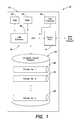
- FIG. 1is a functional block diagram of a computer system configured to implement the universal secure registry (“USR”), including a USR database, according to one embodiment of the invention;
- USRuniversal secure registry
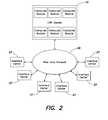
- FIG. 2is a functional block diagram of a first embodiment of a networked environment including the computer system of FIG. 1 ;
- FIG. 3is a functional block diagram of an entry of a database forming the USR database of FIG. 1 ;
- FIG. 4is a functional block diagram of a second embodiment of a networked environment including the computer system of FIG. 1 ;
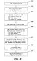
- FIG. 5is a flow chart illustrating steps in a process of inputting data into the USR database
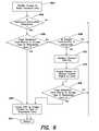
- FIG. 6is a flow chart illustrating steps in a process of retrieving data from the USR database
- FIG. 7is a flow chart illustrating a first protocol for purchasing goods from a merchant via the USR database without transmitting credit card information to the merchant;
- FIG. 8is a flow chart illustrating a second protocol for purchasing goods from a merchant via the USR database without transmitting credit card information to the merchant;
- FIG. 9is a flow chart illustrating a protocol for purchasing goods from a merchant via the USR database by validating the user's check
- FIG. 10is a flow chart illustrating a protocol for purchasing goods from an on-line merchant via the USR database without transmitting credit card information to the on-line merchant, and enabling the on-line merchant to ship the goods to a virtual address;
- FIG. 11is a flow chart illustrating a protocol for shipping goods to a virtual address via the USR database
- FIG. 12is a flow chart illustrating a protocol for telephoning a virtual phone number via the USR database
- FIG. 13is a flow chart illustrating a protocol for identifying a person via the USR database
- FIG. 14is a flow chart illustrating a protocol for identifying a person to a policeman via the USR database
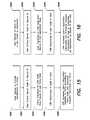
- FIG. 15is a flow chart illustrating a protocol for providing information to an authorized recipient of the information via the USR database
- FIG. 16is a flow chart illustrating a protocol for providing application information to an authorized recipient of the information via the USR database
- FIG. 17is a functional block diagram of an embodiment configured to use information in the USR system to activate or keep active property secured through the USR system;
- FIG. 18Ais a functional block diagram of an embodiment configured to use the USR system to control access to a secure computer network
- FIG. 18Bis a functional block diagram of another embodiment configured to use the USR system to control access to a secure computer network
- FIG. 19is a flow diagram of a process for controlling access to a secure computer network with the USR system in accordance with an embodiment of the invention.
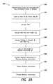
- FIG. 20is a flow diagram of a process for controlling access to a secure computer network with the USR system in accordance with another embodiment of the invention.
- FIG. 21illustrates an embodiment of a system for validating the identity of an individual
- FIGS. 22A and 22Billustrate one embodiment of a process for validating the identity of an individual
- FIG. 23illustrates one embodiment of various fields included within a first wireless signal and a second wireless signal as transmitted by the system of FIG. 21 ;
- FIG. 24illustrates one embodiment of a process for verifying or authenticating the identity of a first user of a first wireless transmission device
- FIG. 25illustrates another embodiment of a process for authenticating the identity of a first user of a wireless transmission device
- FIG. 26illustrates still another embodiment of a process for authenticating the identity of a first user of a wireless transmission device
- FIG. 27illustrates one embodiment of a data structure that can be used by any wireless device of the system of FIG. 21 ;
- FIG. 28illustrates a system in accordance with one embodiment of the invention
- FIG. 29illustrates a process in accordance with an embodiment of the invention.
- FIGS. 30A-30Dillustrate a converter device in accordance with one embodiment of the invention.
- an information systemis formed as a computer program running on a computer or group of computers configured to provide a universal secure registry (USR) system.
- the computerin this instance, may be configured to run autonomously (without the intervention of a human operator), or may require intervention or approval for all, a selected subset, or particular classes of transactions.
- the inventionis not limited to the disclosed embodiments, and may take on many different forms depending on the particular requirements of the information system, the type of information being exchanged, and the type of computer equipment employed.
- An information system according to this inventionmay optionally, but need not necessarily, perform functions additional to those described herein, and the invention is not limited to a computer system performing solely the described functions.
- a computer system 10 for implementing a USR systemincludes at least one main unit 12 connected to a wide area network, such as the Internet, via a communications port 14 .
- the main unit 12may include one or more processors (CPU 16 ) running USR software 18 configured to implement the USR system functionality discussed in greater detail below.
- the CPU 16may be connected to a memory system including one or more memory devices, such as a random access memory system RAM 20 , a read only memory system ROM 22 , and one or more databases 24 .
- the database 24contains a universal secure registry database.
- the inventionis not limited to this particular manner of storing the USR database. Rather, the USR database may be included in any aspect of the memory system, such as in RAM 20 , ROM 22 or disc, and may also be separately stored on one or more dedicated data servers.
- the computer systemmay be a general purpose computer system which is programmable using a computer programming language, such as C, C++, Java, or other language, such as a scripting language or even assembly language.
- the computer systemmay also be specially programmed, special purpose hardware, an application specific integrated circuit (ASIC) or a hybrid system including both special purpose components and programmed general purpose components.
- ASICapplication specific integrated circuit
- the processoris typically a commercially available microprocessor, such as Pentium series processor available from Intel, or other similar commercially available device.
- a microprocessorexecutes a program called an operating system, such as UNIX, Linux, Windows NT, Windows 95, 98, or 2000, or any other commercially available operating system, which controls the execution of other computer programs and provides scheduling, debugging, input/output control, accounting, compilation, storage assignment, data management, memory management, communication control and related services, and many other functions.
- the processor and operating systemdefines a computer platform for which application programs in high-level programming languages are written.
- the database 24may be any kind of database, including a relational database, object-oriented database, unstructured database, or other database.
- Example relational databasesinclude Oracle 81 from Oracle Corporation of Redwood City, Calif.; Informix Dynamic Server from Informix Software, Inc. of Menlo Park, Calif.; DB2 from International Business Machines of Armonk, N.Y.; and Access from Microsoft Corporation of Redmond, Wash.
- An example object-oriented databaseis ObjectStore from Object Design of Burlington, Mass.
- An example of an unstructured databaseis Notes from the Lotus Corporation, of Cambridge, Mass.
- a databasealso may be constructed using a flat file system, for example by using files with character-delimited fields, such as in early versions of dBASE, now known as Visual dBASE from Inprise Corp. of Scotts Valley, Calif., formerly Borland International Corp.
- the main unit 12may optionally include or be connected to an user interface 26 containing, for example, one or more input and output devices to enable an operator to interface with the USR system 10 .
- Illustrative input devicesinclude a keyboard, keypad, track ball, mouse, pen and tablet, communication device, and data input devices such as voice and other audio and video capture devices.
- Illustrative output devicesinclude cathode ray tube (CRT) displays, liquid crystal displays (LCD) and other video output devices, printers, communication devices such as modems, storage devices such as a disk or tape, and audio or video output devices.
- the user interface 26may be omitted, in which case the operator may communicate with the USR system 10 in a networked fashion via the communication port 14 . It should be understood that the invention is not limited to any particular manner of interfacing an operator with the USR system.
- the inventionis not limited to a particular computer platform, particular processor, or particular high-level programming language.
- the computer systemmay be a multiprocessor computer system or may include multiple computers connected over a computer network.
- each module or step shown in the accompanying figures and the substeps or subparts shown in the remaining figuresmay correspond to separate modules of a computer program, or may be separate computer programs. Such modules may be operable on separate computers.
- the data produced by these componentsmay be stored in a memory system or transmitted between computer systems.
- Such a systemmay be implemented in software, hardware, or firmware, or any combination thereof.
- the various elements of the information system disclosed herein, either individually or in combination,may be implemented as a computer program product, such as USR software 18 , tangibly embodied in a machine-readable storage device for execution by the computer processor 16 .
- Various steps of the processmay be performed by the computer processor 16 executing the program 18 tangibly embodied on a computer-readable medium to perform functions by operating on input and generating output.
- Computer programming languages suitable for implementing such a systeminclude procedural programming languages, object-oriented programming languages, and combinations of the two.
- the computer system 10may be connected to a plurality of interface centers 27 over a wide area network 28 .
- the wide area network 28may be formed from a plurality of dedicated connections between the interface centers 27 and the computer system 10 , or may take place, in whole or in part, over a public network such as the Internet.
- Communication between the interface centers 27 and the computer system 10may take place according to any protocol, such as TCP/IP, ftp, OFX, or XML, and may include any desired level of interaction between the interface centers 27 and the computer system 10 .
- communications facilitating or relating to transmission of data from/to the USR database 24 or the computer system 10may be encrypted using an encryption algorithm, such as PGP, DES, or other conventional symmetric or asymmetric encryption algorithm.
- an encryption algorithmsuch as PGP, DES, or other conventional symmetric or asymmetric encryption algorithm.
- the USR system 10 or USR database 24may be able to authenticate its identity to a user or other entity accessing the system by providing an appropriate code which may be displayed on the user's smart card, for example a SecurIDTM card or its equivalent, or other code generator, for example a single use code generator, being employed by the user.
- a comparison by the user or the code generator between the provided number and an expected numbercan validate, to the user (or other entity) or the code generator, that communication is with the database and not an imposter.
- a challenge-response protocolis employed to authenticate the identity of the USR system and/or the user to the other.
- the database 24 shown in FIG. 1has a USR database containing entries related to persons 1 -n.
- the data in the USR databasemay also be segregated, as shown in FIG. 4 , according to data type to enable individual computer modules to handle discrete applications on discrete data types. Segregating the data, as illustrated in FIG. 4 , may make access to the database more robust by enabling portions of the data in the USR database 24 to be accessible even when it is necessary to perform maintenance on a portion of the database.
- storing the data in the USR database 24 according to the scheme illustrated in FIG. 1may make it easier for a user of the database to make changes to multiple types of data simultaneously or in a single session.
- each entry 30 in the database 24may contain multiple types of information.
- the entrycontains validation information 32 , access information 34 , publicly available information 36 , address information 38 , credit card and other financial information 40 , medical information 42 , job application information 44 , and tax information 46 .
- the inventionis not limited to a USR containing entries with all of this information or only this particular information, as any information on a person or other entity such as a company, institution, etc. may be stored in USR database 24 .
- each databasewill typically include at least the validation and access information to enable the USR software to correlate a validation attempt with a verified validation, and to enable the USR software to determine access privileges to the requested data.
- databasesmay be linked to permit information not in a main USR database to be retrieved, with validation/identification for all databases accessed being done at the USR system.
- the validation informationis information about the user of the database to whom the data pertains and is to be used by the USR software 18 to validate that the person attempting to access the information is the person to whom the data pertains or is otherwise authorized to receive it.
- the validation informationmay be any type of information that will reliably authenticate the identity of the individual.
- the informationmay include any of a secret known by the user (e.g., a pin, a phrase, a password, etc.), a token possessed by the user that is difficult to counterfeit (e.g., a secure discrete microchip), and/or a measurement such as a biometric (e.g., a voiceprint, a fingerprint, DNA, a retinal image, a photograph, etc.).
- a secret known by the usere.g., a pin, a phrase, a password, etc.
- a token possessed by the user that is difficult to counterfeite.g., a secure discrete microchip
- a measurementsuch as a biometric (e.g., a voiceprint, a fingerprint, DNA, a retinal image, a photograph, etc.).
- the user's identifying informationmay be manually entered or scanned at the interface center.
- a variety of types of communicationmay be employed to communicate the user's identifying information from the identification card or token to the computer system.
- near field signalmay be employed to communicate information between the identification card or token and the computer system 10 .
- the user's identifying informationis included in (or entered via) the user's cell phone where it is then communicated to the computer system 10 .
- the cell phoneis also configured to receive information from the computer system 10 at the interface center 27 .
- the user of the databasewill carry a SecurIDTM card available from RSA Security, formerly Security Dynamics Technologies, Inc., of Cambridge, Mass. Use of this card enables secure access to the USR database without requiring the user to transmit any personal information.
- the cardretrieves a secret user code and/or time varying value from memory and obtains from the user a secret personal identification code.
- the cardmathematically combines these three numbers using a predetermined algorithm to generate a one-time nonpredictable code which is transmitted to the computer system 10 .
- the computer systemspecifically USR software 18 , utilizes the received one-time nonpredictable code to determine if the user is authorized access to the USR database and grants access to the USR database if the user is determined to be authorized.
- the verification information 32 in the database entry in the embodiment of the invention illustrated in FIG. 3contains information to enable the USR software 18 to validate the user using such a card in this manner.
- identification cards or tokensmay likewise be used.
- other smart cardsmay be used which generate non-predictable single use codes, which may or may not be time varying, or other access code generators may be used.
- An algorithm generating such non-predictable codesmay also be programmed onto a processor on a smart card or other computing device, such as a cell phone, pager, ID badge, wrist watch, computer, personal digital assistant, key fob, or other commonly available electronic device.
- a smart card or other computing devicesuch as a cell phone, pager, ID badge, wrist watch, computer, personal digital assistant, key fob, or other commonly available electronic device.
- the term “electronic ID device”will be used generically to refer to any type of electronic device that may be used to obtain access to the USR database.
- biometric informationmay be stored in the verification area of the database entry to enable the identity of the user possessing the identifying device to be verified at the point of use.
- biometric informationexamples include a personal identification number (PIN), fingerprint, voice print, signature, iris or facial scan, or DNA analysis.
- PINpersonal identification number
- the verifying section of the databasemay contain a picture to be transmitted back to the person seeking to validate the device to ensure the person using the device is the correct person.
- the identifying deviceitself may also be provided with a picture of the person authorized to use the card to provide a facial confirmation of the person's right to use the card.
- a challenge-response protocolmay be employed in combination with or as an alternative to the preceding to validate the person attempting to access the information.
- Various embodimentsmay employ a challenge-response protocol with or without an identification card.
- the Access information 34is provided to enable different levels of security to attach to different types of information stored in the entry 30 in the USR database 14 .
- the personmay desire that their address information be made available only to certain classes of people, for example colleagues, friends, family, Federal Express, U.P.S., and the U.S. mail service.
- the names or universal identifiers for those selected individuals, companies, organizations and/or agenciesmay be entered into appropriate fields in the Access information to specify to the USR software 18 those individuals to whom the address information may be released.
- access fieldsmay be specified for the other types of information.
- the individualmay specify that only particular individuals and/or companies have access to the credit card and other financial information 40 , medical information 42 , job application information 44 and tax information 46 . Additionally, the individual may specify that no one have access to that information unless the individual participates in the transaction (see FIG. 6 ).
- the USR software 18contains algorithms for execution by the CPU 16 that enables the CPU 16 to perform the methods and functions of the USR software described below in connection with FIGS. 5-16 .
- the USR software 18in this embodiment, performs all functions associated with validating an electronic ID card. If desired, a separate validation software module may be provided to validate electronic ID devices outside of a firewall segregating the validation information from other user information.
- This algorithmcomprising the USR software 18 may be used to implement, in one exemplary embodiment, a USR system configured to enable selected information to be disseminated to selected individuals in a secure and dynamic fashion. This information may be used for numerous purposes, several of which are set forth below and discussed in greater detail in connection with FIGS. 5-16 .
- the USR systemmay be used to identify the person, enable the person to be contacted by telephone or mail anonymously, enable the person to be contacted by telephone or by mail without revealing the person's telephone number or present location, enable the person to purchase items over the Internet or in a store without revealing to the merchant any personal identification information or credit card information, enable the person to complete a job application without completing a job application form, enable the police to discern the person's identity and any outstanding warrants on the individual, and numerous other uses.
- the inventionis not limited to these several enumerated uses, but rather extends to any use of the USR database. The methods of using the USR database 24 will now be discussed in connection with FIGS. 5-16 .
- FIG. 5illustrates a method of training the USR database 24 .
- the USR software 18first validates the person's identification ( 500 ).
- the initial validation of the person's identification ( 500 )may take place at the point of sale of an electronic ID device (for example, a smart card). This may be done in any conventional manner, such as by requiring the person to show a government issued identification card, passport, birth certificate, etc.
- an electronic ID devicefor example, a smart card
- the USR software 18determines if the person has rights to enter data into the system ( 502 ). This step enables the system to charge persons for maintaining information in the USR database 24 .
- the USR software 18may poll a database of current accounts or a database of accounts that are currently in default to determine if the person has paid the access fee to enter data into the database.
- a similar account status inquiry processmay be performed by the USR software 18 in connection with each of the other methods set forth in FIGS. 6-16 . If the person is not authorized to enter data into the USR database 24 , the person is notified of the status of their account and the process returns ( 512 ) to wait for further input from another person. Alternatively, a person may be permitted to enter some classes of data into the system and update such classes of data at no charge, with a fee possibly being required for other classes of data, for example medical records. This would facilitate a more robust database.
- the USR software 18then enables the person to enter basic personal data into the USR database 24 ( 504 ).
- personal datamay be one class of data the USR software 18 allows the person to enter into the USR database 18 regardless of account status, i.e., for free.
- the USR software 18will then check to see if the person has additional rights to enter additional data ( 506 ), such as data to be entered into one of the other categories of data in FIG. 3 .
- additional datasuch as data to be entered into one of the other categories of data in FIG. 3 .
- this step of checking the person's rights to enter data ( 506 )may be combined with the initial check ( 502 ). If the person does not have rights to enter any further data, the USR software 18 notifies the user and returns ( 512 ).
- the USR software 18determines that the person has the right to enter additional data into the USR database 24 , the person is prompted through the use of appropriate prompts, provided with forms, and otherwise enabled to enter advanced personal data into the USR database 24 ( 508 ). For each type of data entered, the person is asked to specify the type of access restrictions and/or whom should be allowed to access the advanced personal data ( 510 ). When the person has completed entering data into the database, the process returns ( 512 ) and commits the data to the database.
- the databasemay perform an integrity check to ensure the absence of conflict in the data before committing the new data to the database.
- the databasewill generally allow anyone to access basic personal data on anyone without performing any authorization check ( 600 ).
- the USR software 18queries whether the requester has the right to access the type of requested data ( 602 ).
- the process of determining the requestor's rights ( 602 )typically involves validating the requestor's identity and correlating the identity, the requested information and the access information 34 provided by the person to the USR database during the training process described above with respect to FIG. 5 .
- the USR software 18determines that the requester has rights to access the type of requested data ( 604 )
- the USR software 18instructs the USR database 24 to enable access to the type of requested data ( 606 ).
- the actual step of enabling access to the type of requested datamay involve multiple steps of formulating a database query, querying the USR database 24 , retrieving the results, assembling the results into a user friendly or user readable format, and transmitting the information to the user.
- the USR software 18determines that the requester does not have the appropriate rights to access the type of requested data ( 604 ). If the USR software 18 determines that the requester does not have the appropriate rights to access the type of requested data ( 604 ), the USR software 18 checks to see if the person is participating in the transaction ( 608 ). Checking to see if the person is participating in the transaction enables the user to authorize access to the requested data in real time. For example, a person may wish to participate in a transaction to give a potential employer one-time access to job application information 44 (see FIG. 3 ). If the person is not participating in the transaction, the USR software 18 determines that the requester is not authorized to have access to the requested data, notifies the requester of this determination, and ends ( 610 ).
- the USR software 18validates the person's identity ( 612 ) and enables the person to change access rights to the data ( 614 ). If the USR software 18 is not able to validate the person's identity, the USR software 18 refuses to allow the person to update the database, notifies the person and/or requester of this determination, and returns ( 610 ).
- a personmay be required to grant access to certain data, for example financial data such as account numbers, under duress.
- the systemmay provide the person with the ability to safely signal this when accessing the system by using a selected access code or by making a known modification to the access code provided by the electronic ID device. On receiving such code, the system would take appropriate steps to protect the person, including for example alerting the police, tracking the person's location to the extent possible, providing traceable data, and the like.
- step 616may seem redundant, given the fact that the person is participating in the transaction and has just previously changed access rights to the database to enable the requester to have access to the data, step 616 is actually useful at preventing a different type of fraud. Specifically, the requester may not be forthright with the person regarding the type of information they are requesting. If step 616 were omitted, the USR software 18 may inadvertently allow access to an unauthorized type of information in the situation where the requester has surreptitiously requested multiple types of data.
- the USR software 18determines that the requester has rights to the type of data requested ( 616 ), it causes the USR database to enable access to the type of requested data ( 606 ). Otherwise, it notifies the requestor of the decision to deny access to the requested data and returns ( 610 ).
- FIG. 7illustrates one embodiment of a method of using the USR software 18 and USR database 24 to purchase goods or services from a merchant without revealing to the merchant account information relating to the person's bank or credit card.
- a userinitiates a purchase ( 700 )
- the userenters a secret code in the user's electronic ID device ( 702 ) to cause the ID device to generate a onetime code or other appropriate code, and presents the electronic ID device with the code to the merchant or otherwise presents the code to the merchant.
- the merchanttransmits to the credit card company (1) the code from the electronic ID device, (2) the store number, (3) the amount of the purchase ( 704 ), and the time of receipt of the code.
- the credit card companytakes this information and passes the code from the electronic ID device to the USR software 18 ( 706 ).
- the USR software 18determines if the code is valid, or was valid at the time offered, and if valid accesses the user's credit card information and transmits the appropriate credit card number to the credit card company ( 708 ). While the link between the USR system and the credit card system is a secure link, there is always a danger that the link may be penetrated and credit card numbers obtained. This may be avoided by instead transmitting, on approval, a multidigit public ID code for the credit card holder which the credit card company can map to the correct credit card number. Even if the link is violated, the public ID code is of no value and the secure link prevents this code from being improperly sent to the credit card company.
- the credit card companychecks the credit worthiness of the user and declines the card or debits the user's account in accordance with its standard transaction processing system ( 710 ). The credit card company then notifies the merchant of the result of the transaction ( 712 ). In this embodiment, the user has been able to purchase goods or services from a merchant without ever providing to the merchant the credit card number. Since the electronic ID device generates a time variant code or otherwise generates a code that can for example only be used for a single transaction, the merchant retains no information from the transaction that may be fraudulently used in subsequent transactions.
- FIG. 8Another embodiment of a system for facilitating purchase of goods or services without providing financial information to the merchant is set forth in FIG. 8 .
- the userinitiates a purchase ( 800 ), enters a secret code in the electronic ID device ( 802 ) and presents the resultant code to the merchant.
- the merchanttransmits to the USR software 18 , (1) the code from the electronic ID, (2) the store number, and (3) the amount of the purchase ( 804 ).
- the USR software 18determines if the code is valid ( 806 ) and, if valid, accesses from the USR database 24 the user's credit card information ( 808 ).
- the USR softwarethen transmits to the credit card company (1) the credit card number, (2) the store number, and (3) the amount of purchase ( 808 ).
- the information in this embodiment transmitted to the credit card companyis intended to be in a format recognizable to the credit card company. Accordingly, the invention is not limited to transferring from the USR system 10 to the credit card company the enumerated information, but rather encompasses any transfer of information that will enable the use of the USR system 10 to appear transparent to the credit card company.
- the credit card companythen processes the transaction in a standard fashion, such as by checking the credit worthiness of the person, declining the card or debiting the user's account and transferring money to the merchant's account ( 810 ).
- the credit card companythen notifies the USR system 10 the result of the transaction ( 812 ) and the USR software 18 in turn notifies the merchant of the result of the transaction ( 814 ).
- the usercan use the USR system 10 to purchase goods or services from a merchant without providing the merchant with the user's credit card number.
- the interposition of the USR system 10 between the merchant and the credit card companyis transparent to the credit card company and thus requires no or minimal cooperation from the credit card company to implement.
- FIG. 9illustrates one embodiment of a method of using the USR system 10 to verify funds when using a check to purchase goods or services from a merchant.
- the userinitiates a purchase and writes a check to the merchant ( 900 ).
- the checkmay be a conventional check containing identifying information, or may be a check bearing a unique serial number and no identifying information to enable the check to be used anonymously.
- the userenters a secret code into the electronic ID card and presents the resulting code to the merchant along with the check ( 902 ).
- the merchanttransmits to the USR software 18 (1) the code from the electronic ID card, (2) the store number, and (3) the amount of the purchase ( 904 ).
- the checkis an anonymous check, the merchant also transmits to the USR software 18 the check number.
- the USR software 18determines if the code from the electronic ID is valid ( 906 ), and if valid accesses the user's bank information and transmits to the bank: (1) the user's bank account number, (2) the store number, and (3) the amount of the purchase ( 908 ). Optionally, the USR software 18 may additionally inform the bank of the check number.
- the bankpolls its own database to determine if there are sufficient funds in the user's account ( 910 ) and notifies the USR software 18 of the result ( 912 ).
- the USR software 18then, in turn, notifies the merchant of the result of the verification ( 914 ).
- This check verification systemmay take place over an unsecured connection between the merchant and the USR system 10 since the user's bank account information is not sent over the connection between the merchant and the USR system 10 . Moreover, where an anonymous check is used, the merchant is not even provided with the person's name or account information in written form. This provides additional security against unauthorized persons writing subsequent checks.
- the check verification systemmay be conducted over a telephone network, such as by having the merchant call a toll free number or over a network connection such as over the Internet.
- FIG. 10illustrates a method of conducting a transaction with a merchant without requiring the user to provide to the merchant the user's name, address, or other identifying information, while enabling the merchant to ship the goods to the user.
- Thismay be beneficially employed, for example, in connection with transactions that take place between remote parties in a networked environment, such as the Internet.
- the userinitiates an anonymous purchase by entering a secret code into the electronic ID device and transmitting the result to the on-line merchant ( 1000 ).
- the merchanttransmits this information to the USR software 18 , along with the store number and the amount of the purchase ( 1002 ).
- the merchantmay provide the store number and purchase price to the user and the user may send this information directly to the USR software 18 along with the code from the electronic ID.
- the number from the electronic ID deviceis a time varying number
- the merchantmay also need to input the time the number was received.
- the electronic ID devicemay encode or encrypt the time with the number, the USR software being able to extract time when receiving the number from the merchant. This may not be required where the time varying number varies slowly, for example changing every hour rather then every minute as for some existing such devices.
- the USR software 18determines if the code is valid ( 1004 ) and, if valid, accesses the user's credit card information from the USR database 24 ( 1006 ). The USR software 18 then contacts the user's credit card company, as described above in connection with FIG. 8 ( 1008 ) and notifies the USR software 18 of the result ( 1010 ).
- the USR software 18If the user's credit is declined, the USR software 18 notifies the on-line merchant and the transaction is terminated ( 1012 ). If the user's credit is honored, the USR software 18 polls the USR database 24 for the user's address and/or address code ( 1014 ). Address codes are discussed below in greater detail with reference to FIG. 11 . The merchant then packages the goods into a parcel, labels the parcel with the appropriate address and/or address code and ships the parcel to the user ( 1016 ). Having the USR system 10 provide the address and/or address code to the on-line merchant enables the user to purchase items in a networked environment without requiring the user to input address information in connection with every sale.
- FIG. 11illustrates a use of the USR database 24 to deliver mail to a user without requiring the user to provide address information to the sender.
- Thismay be useful in many contexts.
- the usermay wish that the address information be known only by the post office.
- using the USR database 24 according to the method of the invention described belowwill enable the user to receive parcels without requiring the user to provide the merchant with the address information.
- the user's addressmay change, temporarily, permanently, or frequently. Enabling the sender to send mail by entering a code instead of an address enables the post office to effectively deliver the coded mail to the corresponding address regardless of the frequency with which the address changes or the duration in which the address will remain valid.
- the userprovides an address code on a public area of the USR database 24 that is available to all persons to see ( 1100 ).
- This codemay for example be six alpha characters, which should be adequate for currently anticipated system populations.
- the usermay provide this code directly to a merchant or other person desirous of sending the person one or more parcels.
- the useralso provides address information to the address information area 38 of the user's entry in the USR database 24 ( 1102 ). Access to the address information 38 is restricted by a rule or other appropriate entry in the access information 34 of the user's entry to only permit mail, parcel or other material delivery services, such as the US mail, UPS and Fed Ex to access the address information.
- the senderretrieves the user's address code from the USR database 24 or otherwise receives the address code from the user, and prints the address code on the parcel ( 1104 ).
- the delivery serviceaccesses the USR software 18 , validates its identity, and queries the USR database 24 for address information corresponding to the address code ( 1106 ).
- the USR database 24retrieves the appropriate address data and provides the address information to the delivery service.
- the delivery servicethen either prints out an address label, prints a machine readable bar code to be attached to the package, or correlates an entry in a delivery database between the address code and the user address ( 1110 ).
- the delivery serviceuses this retrieved information to deliver the package to the user while never supplying the merchant with the user's permanent or temporary address.
- a usermay also assure that mail, parcels, etc. are delivered to a current location by providing only a single notice to the USR system, regardless of how frequently the person moves.
- the personcan also automatically provide for address changes where the person moves according to a known schedule.
- deliveries to be made on a weekdaycould be directed to one address and deliveries on a weekend to another address; or deliveries during winter months to one address and during summer months to a different address.
- FIG. 12illustrates a method of enabling a person to telephone a user of the USR system 10 without providing the user's telephone number to the person.
- the userprovides a telephone code on the publicly available area of his entry on the USR database 24 ( 1200 ). This code may be assigned by the USR software 18 or made up by the user.
- the useralso provides the USR database 24 with actual telephone information to enable the USR system 10 to connect callers with the user ( 1202 ).
- the person wishing to telephone the user of the USR system 10calls a telephone number and enters the telephone code of the user ( 1204 ).
- the USR software 18may require the person to identify themselves to see if they are authorized to call the user. Assuming that the person is authorized to call the person, or if no authorization check is performed, the USR connects the person to the telephone number in the USR database 24 without providing the person with the telephone number.
- Enabling the user to specify the telephone numbermay be advantageous for many reasons.
- the usermay frequently be switching between telephone coverage areas and may wish to be reachable at all times.
- Simply by instructing the USR database 24 to connect incoming telephone calls to one of a myriad of numberswill facilitate connecting the incoming calls to, for example, the user's cell phone, work phone, pager, car phone or home phone, without necessitating the user to provide all these numbers to the caller.
- a similar systemmay be implemented for facsimile transmissions, e-mails or other communications.
- the useralso may have predefined rules to enable telephone calls to follow a set pattern. For example, the user may desire to receive telephone calls only from family members during the night time at home, may wish to have all incoming calls routed to a car phone during commuting hours, and may wish to have all incoming calls routed to a cell phone during lunch.
- time dependent rulesmay and/or caller specific rules may be entered into the USR database to specify accessibility and connectivity of incoming telephone calls.
- the publicly available address code and telephone code and any other codesmay be the same, or may be different, there being some advantages to having a single code usable for all such applications for each person on the system.
- the codescould be accessible through a variety of media including telephone and the Internet. Where two or more people on the system have the same name, which will frequently be the case, additional publicly available biographical data may be provided with the name to assure that the right code is selected.
- the systemmay similarly be used to provide public keys for use in a public key/private key encryption system, to provide other public codes for an individual or to provide other public information. Access to such information would typically be unrestricted.
- the public code used to obtain the key, or possibly the public key itselfmay be used as above to obtain the e-mail address, telephone number or the like for the person to whom the message is being sent, and the USR system may also be used to perform the encryption.
- the recipientreceives the message, he deencrypts it using the recipient's private key in standard fashion, including deencrypting the name of the sender. However, this does not necessarily verify the sender and such verification may be desirable for important messages, particularly ones involving large financial transactions.
- the USR systemmay accomplish such verification by also storing private keys for people in the system.
- the senderfirst authenticates himself to the system, and the system then adds a second signature to the message which is encrypted with the sender's private key.
- the receiving partydeencrypts this signature with the sender's public key. Since the system only sends such signatures for authenticated users, the message is thus verified.
- FIG. 13illustrates a general method of using the USR database 24 to authenticate a user's identification. This may be used in connection with any of the other methods disclosed herein to ensure that the electronic ID device has not been stolen and/or hacked by an unauthorized holder.
- the userattempts to prove identification to a validator, such as to prove that the possessor of the electronic ID device is of sufficient age to purchase alcohol ( 1300 ).
- a validatorsuch as to prove that the possessor of the electronic ID device is of sufficient age to purchase alcohol ( 1300 ).
- the userenters a secret code into the electronic ID ( 1302 ).
- the validatortransmits to the USR software 18 the code from the electronic ID ( 1304 ). If the USR software 18 determines that the code is valid ( 1306 ), it accesses the user's photograph, age information, or any other desired information, and transmits that information to the validator ( 1308 ).
- the validatorcan ensure that the person using the electronic ID card is the proper person. Likewise, the validator can ensure, based on the information provided by the USR system 10 , that the person is as old as the person claims to be.
- FIG. 14A specific embodiment of this identification validation procedure is illustrated in FIG. 14 .
- a policemantakes the place of the validator.
- the policemanmay also receive additional information, such as the user's police records, records of any arrests, outstanding warrants, and other similar information that may be of use to the policeman when determining how to handle a particular individual.
- FIG. 15illustrates a process for enabling the user to provide specific information to a party, such as medical staff in an emergency room.
- a partysuch as medical staff in an emergency room.
- the userif the user desires to provide information to a party ( 1500 ), the user enters a secret code in the electronic ID device and provides the electronic ID code to the party ( 1502 ).
- the partytransmits to the USR software 18 the ID code and the party code ( 1504 ).
- the party codemay be a code from for example an electronic device which identifies the party, may be a status code which identifies the class of users to which the party belongs, for example policeman, emergency room personnel, doctor, etc. or may be a combination of both, the status code for example being encrypted into the ID code.
- the USR software 18determines if the code is valid ( 1506 ), accesses the user's information in the USR database 24 and transmits available information to the party ( 1508 ).
- the usermay be provided with a plurality of different codes to enter into the electronic ID device depending on the type of information to be released to the party.
- the user's basic codemay be 1234.
- Using multiple codeseliminates any ambiguity about the authority provided by the user to the party, but requires the user to remember additional information.
- the usermay not be in a position to provide the ID code, but would still want medical records provided.
- the release authorization for certain portions of the user's databasecould therefore specify that the information be released to certain class or classes of individuals and the USR system would release such information to individuals or organizations based only on status code.
- the status code of an emergency roomcould alone trigger release of medical data.
- FIG. 16illustrates one embodiment of a method of using the USR database 24 to complete a standard application, such as a job application or an application to rent an apartment.
- This embodimentis a specific example of the more generic method of enabling a party to retrieve information discussed above with respect to FIG. 15 .
- the partymay be provided with the opportunity to provide a form to the USR software 18 , the fields of which may be automatically completed with information from the job application information section of the USR database 24 .
- a usermay also authorize an organization for which a form has been completed using the USR system to receive updates, either in response to a request from the organization or at selected intervals, for example once a year, so as to maintain information in the forms current. Since the user will be providing information to the system on a regular basis, this is a relatively easy and painless way for the user to maintain current information with many organizations the user deals with.
- Another potential use of the systemis to permit a person to be located where only limited biographical information on the person is known.
- Users of the USR system wishing to participate in this featurecould be cued to provide non-confidential biographical data when they come on the system or at any time thereafter when they decide to participate. They can also indicate whether they wish their name given out in response to such an inquiry or to merely be alerted to an inquiry which might involve them and information on the requester.
- a person seeking to find another person or group of peoplecan input appropriate biographical data, for example members of 1975 Harvard University hockey team, or information of a person's last known address plus school information, etc.
- the systemwill then provide a list of persons who meet the listed criteria from which the person making the inquiry can hopefully find the person they are looking for.
- the personwhen a person is located, the person may request that only the person's address code or general access code (i.e. a single code which is used to get current address, telephone, e-mail, etc. information) be provided when the person is located. This can further protect the individual from undesired contacts.
- the person's address code or general access codei.e. a single code which is used to get current address, telephone, e-mail, etc. information
- FIGS. 13-16refer to the entry of a secret code for validation by the USR system
- the processes illustrated for each of FIGS. 13-16may include a challenge-response protocol by which the user's identity is authenticated.
- FIG. 17illustrates another embodiment of the invention.
- the USR system 10may be used to secure expensive personal equipment, such as stereos, televisions, laptop computers, cellular telephones, cars, boats, and other items of value to a person.
- each item to be secured using the USR systemis provided with a USR timer chip imbedded in the electronics. If the USR timer chip is not provided with a code within a predefined period of time, for example every 30 days, the equipment is deactivated.
- a television, mobile phone, laptop computer, automobile, heavy equipment, weapon or facilitymay be provided with a security chip having an internal timer that must be reset before expiration by provision of a particular code.
- the timerWhen reset does not occur, the timer will disable the electronic device or other device using any one of a number of known disablement methods.
- Exemplary codesmay be transmitted in the same manner as beeper signals are conventionally transmitted or may be transmitted to wired devices over the Internet or other public network.
- the USR system 10may be advantageously employed to automatically provide the secured property with the necessary codes at appropriate intervals, unless instructed by the user of the USR system 10 to cease doing so. Alternatively, the USR system 10 may require participation by the user prior to sending out the activation codes.
- the usermay provide to the USR system 10 , information indicative of the codes to be transmitted, timing information, and automation information—i.e., whether the codes should be sent automatically or should require user intervention.
- the USR system 10may notify the user of the upcoming deadline via e-mail or another method.
- This systemmay be useful to secure sensitive equipment other than personal equipment as well, such as military equipment, public equipment, school equipment and any other equipment that is subject to theft.
- FIG. 18Aillustrates another embodiment of the invention that can provide a centralized system to control access to a plurality of secure networks.
- a system 1800may employ the USR 10 to control access to a plurality of secure systems 1804 (e.g., a plurality of secure computer networks).
- the system 1800may include one or more access devices 1802 that can be employed by a user to access a secure computer network included in the plurality of secure systems.
- the system 1800may be employed to protect other secure systems such as secure communication networks and/or other resources that are accessed electronically.
- the system 1800includes a first communication link 1801 that provides a communication path between the access device 1802 and the USR 10 , and a second communication link 1803 that provides a communication path between the USR 10 and the plurality of secure system 1804 .
- each of the first communication link 1801 and the second communication link 1803are wide area networks, for example, the Internet.
- Each of the secure systems 1804can be associated with an organization.
- An organizationis any entity that employs a secure (e.g., restricted access) host system to provide resources to a plurality of users.
- a secure host systeme.g., restricted access
- an organizationmay be a corporation (including a non-profit corporation), partnership, other business entity, an affiliation or individual that employs a secure host system to provide resources to a plurality of authorized users.
- an organizationis not restricted to any particular size, for example, as measured by the number of members or employees.
- each of the secure systems No. 1 , No. 2 , No. 3 , etc.may be associated with a different organization and the USR 10 may control access to each of the secure systems. That is, the USR 10 can provide access control for a plurality of secure computer networks each associated with a different and unrelated organization. Further, each of the secure computer networks may have a different plurality of users who are authorized to access the network.
- the access devicemay include any of a desktop computer, a laptop computer, and a handheld computer (e.g., a PDA, call phone and the like). Further, as shown in phantom, a plurality of access devices may communicate with the USR 10 . Where a web-based system is employed, for example, each of a plurality of computers connected to the Internet may be individually employed as a separate access device to communicate (e.g., independently communicate) with the USR 10 to gain access to one or more of the secure systems 1804 .
- the access device 1802may be a computer employed with a client-server network.
- the userinitiates an access request for a secure system 1804 selected by the user. That is, the user may supply authentication information and a computer network ID to the USR.
- the authentication information and the computer network IDare processed by the USR to authenticate the user and determine whether the user is authorized to access the secure system 1804 that is identified by the computer network ID.
- the USRthen routes communications between the user and the secure system provided that the user authentication is successfully completed.
- the USR 10connects the access device 1802 to one of the secure systems 1804 via a communication path that does not include the USR 10 .
- the USR 10connects the access device 1802 to one of the secure system 1804 via a communication path that does include the USR.
- a system 1810employs a USR 10 to control access to a secure system (e.g., a secure computer network) according to another embodiment.
- the system 1810includes the USR 10 , an access device 1802 , and a plurality of secure system 1804 .
- the userselects from the plurality of secure systems 1804 a secure system that the user would like to access.
- the access device 1802With the access device 1802 , the user communicates authentication information directly to the selected secure system 1804 , e.g., without gaining access to the system.
- the secure systemthen communicates the authentication information and/or information corresponding to the authentication information to the USR 10 .
- the USR 10processes the information received from the secure system and then communicates an indication of whether the authentication information corresponds to one of the plurality of users authorized to access the secure system.
- the secure systemgrants or denies access to the secure system (and the associated resources) based on the indication received from the USR 10 .
- the USR 10can provide a centralized access control system (e.g., an authentication system) for a plurality of secure systems 1804 that are associated with independent organizations that may have no affiliation with one another.
- a first organizationmay be associated with (have resources located on and/or accessed by) the secure system no. 1
- a second organizationmay be associated with the secure system no. 2
- a single organizationmay also be associated with a plurality of the secure systems 1804 .
- the USR 10provides access control to a plurality of secure systems for a single organization.
- the systems 1800 and 1810allow an organization to operate a secure system without hosting the authentication system software or at least without the need to host a substantial part of authentication system software.
- software upgrades/maintenancecan be implemented at the USR 10 (e.g., centrally) for the plurality of secure systems 1804 and specialized authentication software is not required at the access device.
- specialized authentication softwareis also not required at the secure system.
- the USR 10provides a web-based system in which the user employs a web-browser when communicating with the USR 10 and the secure system.
- the USR 10can also provide centralized administration and management for the plurality of secure systems 1804 .
- the centralized administrationcan include routine tasks such as adding or removing authorized users for each of the plurality of secure systems 1804 , for example, based on the hiring or resignation, respectively, of an employee. Additional administrative functions such as maintaining a secure database of private keys associated with each user, generating time varying codes, maintaining encryption software, maintaining audit trails and other functions may also be accomplished in a centralized fashion with the USR 10 for a plurality of organizations.
- the USR 10develops an audit trail by monitoring the communication path to capture information concerning the use of the secure system.
- the USR 10may collect and store information concerning the length of time during which the access device remains connected to the secure system, the type of resources accessed by the user, the type of data transmitted (including the identification of specific documents) during a login period and the volume of data transmitted.
- the USRcontinuously monitors the communication between a plurality of access devices 1802 and a secure computer network and collects information to generate an audit trail for each device.
- the USRdoes not continuously monitor communications. Instead, the secure computer network intermittently (e.g., periodically) transmits audit information to the USR 10 where the audit information may concern one or a plurality of users connected to the network during a specific time period.
- the USR 10may be located in an ultra-secure facility that employs heightened security relative to the security provided by the organizations that it serves.
- the physical facility where the USR is locatedmay meet requirements generally associated with critical military installations.
- the USR 10may be housed in a facility that is hardened against radiation, shielded against electromagnetic interference, and/or protected against earthquakes, hurricanes, etc. to allow operation of the USR during times of general emergency.
- the personnel and hiring policies of the facility operating the USR 10may also be more secure relative to the security measures taken by the organizations associated with the secure systems 1804 . That is, the individuals operating the USR 10 may undergo more rigorous background checks that include a detailed investigation of their personal and employment histories.
- the centralized approach described abovecan provide increased security because the administration of the access control system (e.g., authentication software) is in the hands of a highly trusted third party who has taken heightened security measures regarding the hiring of the administrative personnel, in particular, the personnel who have access to authentication data (e.g., private encryption keys, etc.).
- the access control systeme.g., authentication software
- the USR 10may be geographically remote from the secure systems.
- a useremploys the access device 1802 to connect to more than one of the plurality of secure systems 1804 .
- the useris independently authorized to access separate secure systems 1804 associated with independent organizations.
- the useris authorized to access separate secure systems 1804 each associated with the same organization. In either situation, the user may employ one or more of the authentication procedures described herein before being allowed access to any one of the secure systems 1804 .
- an entityinitiates an access request.
- the access requestwill be initiated when the user or entity inputs information into an access device such as a computer.
- the entitysupplies authentication information and a computer network ID to the USR (e.g., the information is electronically transmitted from the access device to the USR).
- the informationis transmitted via the Internet from the access device to the USR.
- the USRreceives the access request which includes the authentication information and the computer network ID.
- the USRdetermines whether the authentication information is valid for a user.
- the USRincludes a database containing selected data of a plurality of users authorized to access a secure computer network, and may compare the authentication information supplied by the entity with authentication information included in the database to determine whether the authentication information corresponds or is valid for a user. If the authentication information is valid, the process 1900 moves to stage 1910 where the USR determines whether the entity is authorized to access the computer network identified by the computer network ID. If the entity is authorized to access the computer network then the USR may allow communication between the entity and the secure computer network at stage 1912 . As previously indicated, the USR may route communications between the entity and the secure computer network and remain in the communication path employed by the access device to communicate with the secure computer network. Alternatively, the USR may simply provide a connection between the access device and the secure computer network where the communication path provided by the connection does not involve the USR.
- stage 1908if the authentication information supplied by the entity is not valid for any of the plurality of users then the process 1900 moves to stage 1914 where an indication is provided to the entity that access is denied. Similarly, if at stage 1910 the entity is not authorized to access the computer network identified by the computer network ID, an indication is provided that the entity is denied access at stage 1914 . In various embodiments, the entity may be allowed additional opportunities to successfully access the system.
- FIG. 20a process 2000 for controlling access to a secure computer network is illustrated in accordance with one embodiment.
- the process 2000is employed with the system 1810 illustrated in FIG. 18B .
- the entityinitiates an access request at stage 2002 .
- the access requestcan be initiated using an access device and each secure computer network may communicate with a plurality of access devices.
- the entitysupplies authentication information to the secure computer network, for example, by entering the information in a web browser and transmitting the authentication information over the Internet to the secure computer network.
- the secure computer networkreceives the authentication information.
- the secure computer networkcommunicates authentication information to the USR (or information corresponding to the authentication information) to allow the USR to authenticate the access request.
- the USRvalidates the authentication information to determine whether the entity is authorized to access the secure system, and at stage 2014 , the secure system receives an indication from the USR concerning whether the entity is authorized to access the system. In one embodiment, the indication is transmitted from the USR to the secure system via the Internet. At stage 2016 , the secure system grants or denies the entity access to the secure system based on the indication received from the USR.
- the processes 1900 and 2000can be accomplished in a variety of stages that may include any of the stages described above in various combinations and sequences including one or more of the stages described above in combination with one or more additional stages.
- an electronic devicee.g., a keypad, a card reader, a biometric scanner, etc.
- a secure areae.g., a door, a gate, etc.
- the entityinitiates the request using the electronic device.
- the physical facilityincludes all or a portion of the secure computer network.
- the secure systemreceives an indication of whether an entity is authorized to access a physical facility.
- the secure systemcommunicates authentication information to the USR.
- the USRvalidates the authentication information and communicates an indication of whether the entity is authorized to access the physical facility.
- the secure systemreceives the indication and grants or denies the entity access to the physical facility.
- Each of the embodiments described with reference to any FIGS. 18-20may include a challenge-response protocol, for example, to authenticate the identity of the entity and/or the USR system to the other.
- FIG. 21illustrates an embodiment of a system 2100 for validating the identity of an individual or an entity.
- the systemincludes a first wireless device 2110 and a second wireless device 2112 .
- the first wireless device 2110comprises a first wireless transmitter and receiver 2114 , a first processor 2116 and a first memory 2118 .
- the second wireless device 2112comprises a second wireless transmitter and receiver 2120 , a second processor 2122 and a second memory 2124 .
- the first wireless device and the second wireless deviceare configured to wirelessly communicate with each other so that the entity associated with the first wireless device can communicate his identity to the entity associated with the second wireless device.
- first wireless transmitter and the second wireless transmittercan be configured to communicate by any form of a wireless signal such as low power Bluetooth signal, infrared signals, RF signals and electromagnetic signals in general.
- a wireless signalsuch as low power Bluetooth signal, infrared signals, RF signals and electromagnetic signals in general.
- the first wireless device and the second wireless devicecommunicate via near field signal.
- the first wireless devicecan also comprise user interface 2126 that allows the first entity to interact with the first wireless device and can also comprise a display, such as a LCD display, 2128 that allows the first entity to further interact with the first wireless device.
- the first wireless devicecan be configured so that the first entity must enter a PIN identification number, for example, via the user interface to gain access to the wireless device.
- the first wireless devicemay comprise a biometric sensor or detector 2130 that enable the first entity to present biometric data to the first wireless device to gain access to the first wireless device.
- the biometric sensorcan be configured to detect a fingerprint of the first entity.
- the memory 2118also comprises stored biometric data of the first entity, which is compared, for example, by the processor 2116 with the detected biometric data to determine whether the first entity is enabled or should be disabled from using the first wireless device.
- biometric dataneed not be fingerprint data and can be any biometric data known to those of skill in the art
- biometric sensorneed not be a fingerprint sensor and can be any biometric sensor known to those of skill in the art.
- the second wireless device 2112can also be configured as discussed above with respect to the first wireless device, namely with any or all of a user interface 2132 , a display 2134 and a biometric sensor 2136 and can be configured to require any and/or all of a second entity to provide a PIN number, or the second wireless device to match biometric information of the second entity with stored biometric information to enable or disable the second entity to gain access to the second wireless device.
- Each of the first wireless device 2110 and the second wireless device 2112comprise a power source or a power source interface 2138 , 2140 that can be coupled to a power source that provides power to respective devices.
- the power sourcecan be any power source, such as, alkaline batteries, rechargeable batteries, proprietary power sources, and interfaces to power sources such as standard 120 VAC, or an AC to DC conversion device, as well as any other type of power source known to those of skilled in the art.
- each of the first wireless device 2110 and the second wireless device 2112can also comprise an additional wireless transmitter and receiver device 2142 , 2144 , respectively, which enable each of these devices to communicate wirelessly via other wireless communication systems such as, via any cell phone standard, via satellite communications, over wireless area networks, local area networks, wide area networks, as well as any other wireless communication standard know to those of skill in the art.
- either or both of the first wireless device 2110 and the second wireless device 2112can be configured to communicate with a secure database 2146 , as will be discussed in further detail herein.
- either of the first or second wireless devicesmay communicate with the secure database on a periodic basis to update it's corresponding data, or to stay alive as will be discussed herein, or to retrieve information in the secure database that is used in the communication protocol between the first and second wireless devices to verify the identity of at least the first entity.
- communication with a secure databasecan be, for example, via the additional respective wireless transmitters and receivers 2142 , 2144 of the first and second wireless devices, or can be via a network interface 2152 , 2154 of the respective devices, that communicate with a network 2148 and to the secure database 2146 .
- FIG. 22there is illustrated one embodiment of an overall communication process that occurs with the system 2100 of FIG. 21 .
- the processis effected by the system of FIG. 1 so as to identify and authenticate the identity of the first user associated with the first wireless device 2110 to the second user associated with the second wireless device 2112 .
- the communication protocol 200 illustrated in FIG. 22is one embodiment of a protocol that enables secure authentication of the first user of the wireless device 2110 .
- the first user of the first wireless device 2110first authenticates his or herself to the wireless device 2110 , for example as has been discussed above, by either entering a PIN via the user interface 2126 of the first wireless device or by interacting with the biometric sensor of the first wireless device at step 202 .
- a challenge-response protocolis employed in which the first user supplies information (a biometric, a PIN or other information) to authenticate his or herself to the wireless device 2110 . If the user of the device does not enter the correct PIN number or does not match the biometric data stored in memory 2118 of the first authorized user of the device, then the device at a minimum shuts down at step 204 .
- the device 2110can also be configured to automatically delete any portion of or all of the data stored in memory 2118 at step 206 .
- the first wireless devicecan be configured to periodically communicate with the secure database 2146 to remain alive, for example, after the first user of the first device authenticates itself to the first device. If the first device does not communicate with the secure database at such periodic intervals at step 208 , then the first device can be configured to delete any or a portion of the data stored in memory at step 206 .
- the communication protocolalso comprises a second user of the second device to authenticate his or herself to the second device at step 210 .
- the authentication by the second device of the second userby any of the mechanisms discussed herein and above with respect to the first wireless device, including entering a PIN number to the user interface 2132 of the second wireless device or by interacting with the biometric sensor 2136 of the second wireless device.
- the second wireless devicewill at a minimum shut itself down at step 212 .
- the second wireless devicecan be configured to automatically delete a portion of or all of the data stored in the memory 2124 of the second wireless device, should such authentication not be successful at step 214 .
- the second wireless devicecan also be configured at step 216 to communicate with the secure database 2146 within defined periods of time, or even a periodic interval once the second user authenticates himself to the second wireless device, and to delete a portion of or all of the data in memory 2124 should such periodic communication not occur.
- a communication protocolis initiated between the first wireless device 2110 and the second wireless device 2112 at step 218 . If the communication protocol is not a valid communication protocol between the devices, the devices wait until there is a valid communication protocol. If the communication protocol is a valid protocol ( 218 yes), then the first wireless device transmits a first wireless signal containing encrypted authentication information of the first user to the second wireless device 2112 at step 220 . The details of the communication protocol and the encrypted authentication information will be discussed further herein.
- the second wireless device 2112receives the first wireless signal and processes the wireless signal to determine the identity of the first user.
- the authentication of the first userincludes displaying a picture of the first user to the second user on the display 2134 of the second wireless device as a result of the communication from the first wireless device to the second wireless device.
- the user of the second wireless devicecan view the picture on the display and ascertain whether the first user of the first wireless device is who he or she purports to be.
- the second wireless deviceneed not be a device that requires a user to interact with it and can be, for example, an unmanned detection system that receives the first encrypted authentication information and determines from the first authenticated encrypted information whether the first user is authorized to gain access to a secured place, a secure network, or a secure computer, to do whatever the first person is seeking to do. If the first user is not who they purport to be, the communication process goes back to looking for a valid communication protocol. In addition, the process allows the second user or the system associated with the second wireless device to take an appropriate action such as denying access to the secure site at step 224 .
- the communication processallows for the second wireless device to transmit a second wireless signal comprising encrypted authentication information of the second user to the first wireless device at step 226 .
- the communication protocol and the first wireless deviceare configured to authenticate the identity of the second user to the first user at step 228 . It is to be appreciated that the authentication of the second user to the first user can be in any of the manners discussed above with respect to the authentication of the first user of the first device, such as by viewing a picture of the second user as provided on the display 2128 of the first wireless device, by matching one-time information contained in the encrypted authentication information or via a challenge-response protocol.
- either or both of the first wireless device 2110 and the second wireless device 2112may communicate with the secure database 2146 to retrieve additional information at step 230 .
- additional informationcan include for example, a portion of the biographic data of the first user of the first wireless device or of the second user of the second wireless device, or full biometric information of the first user or the second user, which can be communicated back to the respective device and used by the respective device to authenticate the user.
- the informationcan be periodic updates as provided the secure database to the respective device, such as will be described herein, including periodic updates of public keys of a plurality of first users as stored in memory on the second wireless device, or updates to public keys of a plurality of second users as stored in memory on the first wireless device.
- such informationmay include periodic updates of the biometric information of a plurality of first users as stored on the second wireless device or a plurality of second users as stored on the first wireless device, which can comprise for example a portion of the biometric information or all of the biometric information.
- the signalcomprises a header field 302 .
- the header fieldcan be any header field known to those of skill in the art.
- the signalcomprises a public ID field 304 , which can comprise, for example, any of name information, a badge number, an employee number, an e-mail address, a social security number, and the like, of the first user.
- the first wireless signalmay also include a digital signature field 306 containing a digital signature of the first user. For example, the digital signature may be generated with the user's private PKI key.
- the first wireless signalmay comprise a one-time time varying code field 308 that includes a random code as generated by the first wireless device.
- the digital signature field and the one-time code fieldcan be used, for example by the second wireless device, to allow access to a secure place without the need for a user of the second wireless device to interact with the second wireless device to authenticate the first user.
- the digital signature and one time codecan be encrypted with the private key of the first user and transmitted to the second wireless device.
- the second wireless devicecan decrypt the digital signature and one time code with the public key of the first user at steps 402 - 404 to authenticate or not the first user at step 406 .
- the first wireless signalalso comprises a PKI encrypted one-time DES key field 310 comprising a PKI encrypted one-time DES key.
- the first wireless signalcomprises a DES key encrypted biometric data field 312 , which includes at least a portion of biometric data of the first user encrypted with the DES key.
- the public key of a first userfor example, stored in memory 24 of the second wireless device can be used to decrypt the DES key, and the DES key can be used to decrypt at least a portion of the biometric data of the first user to use in the authentication of the identity of the first user.
- the first wireless signalcan also comprise another ID data field 314 , which can contain other information such as name, height, weight, eye color or anything else.
- the embodiment of the wireless signal discussed in FIG. 23has been discussed with reference to the first wireless signal transmitted from the first wireless device 2110 of FIG. 21 to the second wireless 2112 , that the same protocol can be used when transmitting a second wireless signal from the second wireless device 2112 to the first wireless device 2110 to authenticate the identity of the user of the second wireless device to the user of the first wireless device. It is to be further appreciated that various fields of the signal can be used and not all of the fields of the wireless signal are needed to authenticate identity of the user.
- the second wireless devicecan verify the identity of the respondent without necessarily interacting with a second user by decrypting the first user's digital signature from the digital signature field 306 at step 402 and verifying that it is the digital signature of the first user, decrypting the one-time code from the one-time code field 308 at step 404 , and using this information at step 406 to authenticate the first user. If the first user is authenticated at 406 , an appropriate action such as allowing access to the secure site, or computer, or network can be granted.
- the second wireless device at step 522receives the first wireless signal and extracts the PKI encrypted DES key from field 310 .
- the wireless devicelooks up the public key of the first user from memory 2124 [See FIG. 21 ] or from a secure server based on the information provided in the public ID field 304 at step 524 .
- the second wireless deviceuses the first public key to decrypt the PKI encrypted DES key at step 526 .
- the second wireless deviceacts on the DES key encrypted biometric information from the field 312 and uses the decrypted DES key to decrypt the at least a portion of the biometric information of the first user as included in the first wireless signal at step 528 .
- the biometric information included in the first wireless signalis a portion of the biometric information of the first user and the second wireless device is configured to store a remainder of the biometric information of the first user in memory.
- the process 520also comprises looking up the remainder of the biometric information stored in the memory at step 530 and combining the remainder of the biometric information with the decrypted and extracted biometric information to provide complete biometric information of the first user at step 532 .
- the biometric informationcan comprise a digital image of the first user and for such aspects, the digital image can be displayed on display 2134 of the second wireless device so that the second user can ascertain whether the first user associated with the first device is who he or she purports to be.
- the biometric informationcan be fingerprint information, a voiceprint, DNA codes of the first user, or any other biometric information known and used by those of skill in the art.
- the processor 2122 of device 2112can also be configured to process the combined biometric information to authenticate the first user at step 536 .
- FIG. 26there is illustrated another embodiment of a process 620 that can be used to authenticate the identity of the first user at step 222 of the process 200 of FIG. 22 .
- some of the stepsare similar to the steps of the process 520 illustrated in FIG. 25 and accordingly a full description of these steps will not be herein duplicated.
- this embodimentcan be used for example, where the biometric information of the plurality of first users is not stored on the second wireless device 2112 but is instead stored at the secure database 2146 as illustrated in FIG. 21 .
- the second wireless devicecan be configured to interact with the secure database to obtain at least a portion of the biometric information of the first user, rather than storing at least a portion of the biometric information of the first user in memory on the second wireless device.
- the second wireless devicecan receive the first wireless signal including the fields discussed above in respect to FIG. 23 , in particular, the public ID field 304 and optionally the PKI encrypted DES key.
- the PKI encrypted DES keymay be used by this process.
- the second wireless deviceaccesses public key information of the first user from the public keys stored in memory on the second wireless device.
- the public keysmay not be stored on the second wireless device and for such embodiments, the second wireless device will communicate with the secure database to obtain the public key of the first user also at step 624 .
- the second wireless devicetransmits a signal to the secure database comprising public identification number to identify the second device to the secure database, presumably after the second user of the second device has authenticated his or herself to the second device.
- the secure databasedetermines whether the second device is authorized to access the secure database at step 628 . It is to be appreciated that according to some embodiments, this communication between the second wireless device and the secure database can be accomplished with encrypted signals and in some embodiments the encrypted signals can include using time varying one time codes to further secure the communication.
- the processalso comprises transmitting the first public ID from the second wireless device 2112 to the secure database at step 630 , and with this information, the secure database accesses the biometric or identification information of the first user at step 632 .
- the biometric or the at least a portion of the biometric informationcan then be transmitted by the secure database to the second wireless device at step 634 . Again, this transmission can be encrypted and further include time varying or one time codes to further secure the communication.
- the second wireless devicecan use the received portion of the first biometric information and combine it with portion of the first biometric information provided in the first wireless signal, or can receive all of the first biometric information as provided by the secure database and, for example, display it on the display 2134 of the second wireless device 2112 at step 636 , or can process the biometric or identification information at step 638 to determine whether the first user is authenticated.
- a data structure 720that can comprise memory 2124 of the second wireless device 2112 . It is to be appreciated that any or all of the various portions of this data structure can be present in the memory 2124 .
- the memorywill include the private key of the second user at field 722 .
- the private keycan be used, for example, when communicating by the second wireless device to the first wireless device to provide a digital signature of the second entity encrypted with the second user's private PKI key to the first user.
- the memorycan also comprise a plurality of public keys of a plurality of first users at area 724 .
- Such public keys of a plurality of first userscan be used as has been discussed herein in combination with the private key of the first user to decrypt information of the first user.
- the public and private keycan be used to decrypt the DES key of the first user.
- the memorycan also comprise at least a portion of biometric data of a plurality of first users, at area 726 .
- the at least a portion of the biometric data of the plurality of first userscan be combined with the portion of the biometric data provided in the first wireless signal or from the secure database, to create the complete biometric data of the first user for ascertaining or authenticating the identity of the first user as has been described herein.
- the memorycan also comprise biometric data of the second user at field 728 .
- the biometric information of the second usercan be used, for example, as has been discussed herein to compare the biometric data detected by the biometric sensor 2136 of the second wireless device to determine whether the second user is authorized to have access to the second wireless device.
- the data structure 720 of FIG. 27can also comprise the memory 2118 of the first wireless device 2110 , and that any or all of the fields of the data structure 720 can exist in the memory 2118 in the first wireless device.
- the first wireless devicecan access the data structure 720 and the various fields for the same purposes as discussed above with respect to the second wireless device, namely, to provide the first digital signature of the first entity encrypted with the first private key in the first wireless signal, to access the public keys of a plurality of second users for the purpose of decrypting information provided in the second wireless signal, to access at least a portion of biometric information of the second user stored in the field 726 , as well as to compare biometric information of the first user with sensed biometric data provided by the biometric sensor 2130 of the first wireless device.
- the methodcomprises acts of receiving first authentication information about the first entity with the first device, transmitting the authentication information about the first entity to a secure database, determining whether or not the first entity is allowed to access the first device based on the first authentication information, and transmitting an enablement signal to the first device indicating to enable nor not enable the first entity to access the first device.
- the methodalso includes an act of allowing or not allowing operation of the first device based on the enablement signal.
- the act of receiving the first authentication information of the first entitycomprises receiving biometric information of the first entity by detecting the biometric information with the first device.
- the act of transmitting the first authentication information about the first entity to a secure databasecomprises generating a non-predictable signal from the biometric information.
- the act of generating the non-predictable signal from the biometric informationcomprises generating a time varying non-predictable signal from the biometric information.
- the act of receiving biometric information of the first entitycomprises receiving a voice signature of the first entity with the first device and the act of generating the non-predictable signal from the biometric information comprises mixing the voice signature of the first entity with a random code to generate the non-predictable signal.
- the act of transmitting the enablement signal to the first devicecomprises sending the random code to the first device.
- the act of receiving biometric information of the first entitycomprises receiving fingerprint data of the first entity with the first device and the act of generating the non-predictable signal from the biometric information comprises mixing the fingerprint data of the first entity with a random code to generate the non-predictable signal.
- the act of transmitting the enablement signal to the first devicecomprises sending the random code to the first device.
- the act of authenticating the biometric of the first entitycomprises authenticating a voice signature of the first entity.
- the act of authenticating the biometric information of the first entitycomprises authenticating a finger print of the first entity.
- a first wireless deviceincludes a biometric detector comprising a fingerprint detector that detects a fingerprint of the first entity.
- the biometric detectorcomprises a voice signature that detects a voice signature of the first entity.
- the systemcomprises a first wireless device including a processor configured to enable operation of the first wireless device if it receives an enablement signal validating first biometric information of a first entity and configured to generate a non-predictable signal from the biometric information, a first wireless transmitter and receiver configured to transmit a first wireless signal including first encrypted biometric information of the first entity and to receive the enablement signal, a first biometric detector for detecting the first biometric information of the first entity and a secure database configured receive the first wireless signal, to authenticate or not authenticate the first biometric information of the first entity, and to provide the enablement signal validating or not validating the first biometric data of the first entity.
- a first wireless deviceincluding a processor configured to enable operation of the first wireless device if it receives an enablement signal validating first biometric information of a first entity and configured to generate a non-predictable signal from the biometric information
- a first wireless transmitter and receiverconfigured to transmit a first wireless signal including first encrypted biometric information of the first entity and to receive the enablement signal
- the secure databasefurther comprises biometric data of a plurality of first entities.
- the processoris configured to generate the non-predictable signal from the biometric information by generating a time varying non-predictable signal from the biometric information.
- the processoris configured to generate the non-predictable signal from the biometric information by mixing the biometric information of the first entity with a random code to generate the non-predictable signal.
- the secure databaseis configured to transmit the enablement signal to the first device including the random code so as to authenticate the secure database to the first device.
- the systemincludes a memory for storing a private key of the first entity authorized to use the first device.
- FIG. 28illustrates an embodiment of a system 100 that employs a converter device 102 to provide an interface between a user device 104 (e.g., a transaction card, a cell phone, etc.) and a system interface 106 where, for example, the system interface 106 employs a magnetic card reader and the user device 104 is not equipped with a magnetic stripe. That is, in one embodiment, the converter device 102 provides a mode of information transmission between the user device 102 and the system interface 106 which would otherwise be unavailable to the user device 102 .
- the converter device 102provides a modified system 100 that provides compatibility with a greater variety of user devices, for example, user devices such as transaction cards, cell phones or PDAs that are not equipped with a magnetic stripe.
- the converter device 102includes a magnetic stripe emulator 137 communicatively coupled to a wireless signal receiver 140 and adapted to provide a time-varying signal emulating data provided by a magnetic stripe card to a magnetic card reader 152 .
- the user deviceneed not be a “card” and may, for example, take the form of a fob used as a key ring, a cell phone, a watch, a personal digital assistant or any device that can include a wireless transmitter, or a magnetic stripe emulator.
- the user device 104employs near field signal to communicate with the converter device 102 .
- the near field communicationis bi-directional such that the user device 104 may both send and receive wireless communication. That is, the user device includes a transceiver.
- the system interface 106provides an interface to a larger information system (e.g., a financial system, an access control system, a medical records system, and the like) that in one embodiment includes a system processor or controller 110 , a database 112 , a network 114 , other systems 116 , such as a universal secure registry 118 as will be described further herein.
- a system processor or controller 110e.g., a central processing unit (CPU), or the like.
- a database 112may be connected to the network 114 via the communication link 120 A and to the system processor 110 via the communication link 120 B instead of being connected as shown in FIG. 28 .
- the communication linkmay be a wireless communication link, a hardwired communication link, a fiber optic communication link, any communication link used in the art, as well as a combination of any of the preceding or any other any communication link capable of transmitting signals between the elements of the system 100 .
- the system processor 110allows information transfer of both data and instructions, for example, between the interface 106 and one or more databases which may be connected to the system or other network elements.
- the operation of the converter device 102allows a user in possession of the user device 104 to wirelessly communicate information to the device so that the device can be employed to interface with a network system.
- the network systemmay provide a magnetic card reader interface and the converter device 102 provides a magnetic stripe emulator that can interface with the system.
- the overall operation of the system 100includes the communication of information between the user device 104 and the converter device 102 , for example, RF communication. In one embodiment, the communication is bi-directional such that information can be communicated both to and from the user device 104 .
- the converter device 102provides an interface by which information derived from the information being transmitted to or from the user device 104 is transmitted between the converter device and the system interface 106 .
- the system interface 106provides the communication interface between it and the remainder of the system 100 (e.g., processor 110 , database 112 , network 114 , etc.).
- the user device 104includes a processor 122 , a user interface 124 , a wireless transmitter 126 and device indicia 128 .
- the user device 104includes a biometric sensor 130 .
- the processor 122is communicatively coupled to each of the wireless transmitter 126 , the user interface 124 and the biometric sensor 130 .
- the processor 122may include a chip such as a general purpose processor, an application specific integrated circuit (“ASIC”), or a field programmable gate array (“FPGA”) and the like that may execute various programs and/or provide logic inputs and outputs.
- the processor 122may process biometric information received from the biometric sensor 130 to verify the identity of the user before the user can employ the user device 104 .
- Exemplary details of a processor and biometric sensor which are configured to authenticate a fingerprint of a userare disclosed in U.S. published application 2004/0133787, published on Jul. 8, 2004, which is herein incorporated by reference in its entirety.
- the processor 122may also include or be coupled to driver circuitry to drive a display included in the user interface 124 and can be configured to process user input data entered via the user interface 124 .
- the user interface 124includes one or more control inputs (for example, control buttons).
- the wireless transmitter 126can process information provided by the processor and convert the information to an RF signal and can also include an RF antenna that transmits the RF information wirelessly.
- the user devicemay also include an RF receiver that receives a wireless RF signal from the RF antenna and converts the RF signal to an information signal provided to the processor.
- the wireless transmitter and/or receiverneed not be an RF device, it can also be any of a IR device, an optical device, a Bluetooth signal or any other wireless signal transmitter or receiver used in the art.
- the user devicemay also include a power source such as a battery that fits within the device.
- a power sourcesuch as a battery that fits within the device.
- the user deviceremains in a sleep mode until it is placed in the vicinity of an RF transmitter at which time the user device 104 converts received RF energy into electrical energy used to provide power to the processor 122 and the other components included in the user device 104 .
- the user device 104can be a smart card configured for wireless signal transmission using RF signals.
- the wireless transmitter 126may be an RF transmitter device or any other wireless transmitter device configured to transmit the smart card information of the card.
- the cardcan be many cards such as a debit card, a plurality of credit cards such as VISA, MasterCard, American Express, or any other card with the card indicia and relevant information being stored in card memory 129 and read out by processor 122 and provided to the wireless transmitter 126 .
- the user device 104need not be in the form of a card and may instead include a cell phone or PDA.
- the converter device 102includes a substrate 132 which may include a stripe 134 and a magnetic field generator 136 which together comprise the magnetic stripe emulator 137 , a processor 138 , a wireless receiver 140 , a user interface 142 , a memory 144 , and a power source 146 .
- the converter device 102includes an indicating light 148 (e.g., an LED) and an output device 150 .
- the system interface 106 with which the converter device 132 is employedincludes any of or all of a magnetic card reader 152 , a wireless transceiver 154 and a data port 156 .
- the converter device 102receives a wireless signal from the user device 104 , processes the information that is received and provides an output in the form of a time-varying signal provided to the stripe 134 (e.g., a magnetic stripe).
- the signal provided to the stripe 134can then be provided to the system processor 110 by inserting the stripe and the associated substrate 132 or portion thereof in the magnetic card reader of the system interface 106 . That is, in one embodiment, the stripe 134 and at least a portion of the substrate 132 can be either slid by the magnetic card reader 152 or inserted to sit statically in front of the read head of the card reader.
- the processor 138may be a general purpose processor, an application specific integrated circuit (“ASIC”), or a field programmable gate array (“FPGA”) and may be implemented in hardware, software, firmware or any combination of the preceding.
- the processor 138may be communicatively coupled with any of the magnetic field generator 136 the wireless receiver 140 , the memory 144 , the user interface 142 , the light source 148 , the power source 146 and the output device 150 .
- the processorcan be configured to receive inputs from one or more of the preceding elements and may provide outputs to each of the elements included in converter device 138 .
- the magnetic stripe 134is a programmable magnetic stripe and the magnetic field generator 136 generates a magnetic signal that controls the information provided by the magnetic stripe 134 .
- the U.S. patent application Ser. No. 10/680,050filed Oct. 7, 2003, entitled “System Method and Apparatus for Enabling Transactions Using a Biometrically Enabled Programmable Magnetic Stripe” which was published on Jul. 8, 2004 as US2004/0133787 (the '050 application), provides further details concerning embodiments of the user device that emulates a magnetic stripe and may also include, for example, a biometric sensor.
- the '050 applicationis incorporated herein by reference in its entirety.
- the processor 138may control the operation of the magnetic field generator 136 to provide the desired information to the stripe 134 .
- the processor 138may provide an output to the stripe 134 in response to receiving information from the wireless receiver 140 , where the information from the wireless receiver is information transmitted from the user device 104 .
- the processor 138may be configured to provide signals to drive a display included in the user interface 142 and process user input data entered with the user interface 142 .
- the user interface 142includes a display screen that can be used to display an image of the user to whom the user device 104 belongs, for security purposes.
- the image to be displayed by the UIcan either be part of the information transmitted by the user device 104 , for example, where the user device 104 also requires some authentication by the user before transmitting the device information and image, or can be provided, for example, by the USR system 118 through the system interface 106 as part of the user authentication process, as will be described in more detail herein.
- the user interface 142may include a plurality of control elements that allow the user and/or the transaction processor (e.g., store clerk, security guard, medical service provider, etc.) to enter information into the converter device 102 .
- the user interface 142includes an LCD display.
- the processor 138may also be configured to provide signals to operate the indicating light 148 .
- the indicating light 148may provide an indication of the operational status of the converter device 102 , for example, the indicating light 148 may indicate any of the following: that the converter device 102 is receiving a transmission from a user device 104 ; that the converter device 102 has generated output data to the stripe 134 ; the status of the power source 146 is normal or conversely that the power source has a low power level; that the converter device 102 is transmitting information via the output device 150 ; that the converter device 102 is properly aligned with the magnetic card reader 152 ; that the converter device 102 has received authorization for a transaction; and the like.
- the indicating lightmay be a single lamp or a plurality of lamps and that the lamp or lamps may be a single color including white or may included a plurality of colors. Further, it should also be apparent that the lights may provide a plurality of status indications based on their color, intensity, rate of change of the preceding characteristics or any combination of these and other features.
- the power source 146may include a battery power source or other energy sources suitable for the form factor of the converter device 102 .
- the power source 146may be any one of a standard size battery (e.g., a AA battery).
- the power sourceis a lithium battery.
- the power sourcecan be any of an AC power source, an AC to DC converter device, or any other DC power source known to those skilled in the art.
- the converter device 102includes a power bus 158 that provides a path for the transmission of power to the various components included in the converter device 102 .
- the converter device 102includes the output device 150 .
- the output devicecan be any standard interface device to be coupled to a data bus such as a USB device, or the output device can be configured for contactless communication with the system interface 106 .
- the output deviceis an optical transmitter device.
- the communication between the converter device 102 and the system interface 106is bi-directional such that information (e.g., information associated with the user's identity) may be transmitted to the system interface 106 , the system processor 110 may generate a response (e.g., a transaction approval), and the response may transmitted to the converter device 102 via the system interface 106 .
- the processor 138is configured in combination with the output device 150 to provide an encrypted output signal. In a further embodiment, the processor 138 is configured in combination with the output device 150 to provide a time-varying encrypted output signal. In yet another embodiment, the processor 138 is configured in combination with the output device 150 to provide a time-varying encrypted (or not) public and private key output signal. In addition, the processor can also be configured in combination with the wireless receiver to receive and decrypt any and all of an encrypted signal, a time-varying encrypted signal and a signal encrypted with a private key as provided by the user device 104 . A challenge-response protocol may also be employed alternatively or in addition to any of the preceding.
- an information exchange between the user device 104 and the converter device 102includes a first piece of information transmitted from the user device 104 to the converter device 102 and a subsequent challenge (e.g., an encrypted challenge) generated by the converter device and transmitted from the converter device to the user device 104 .
- the useremploys the user device to respond to the challenge.
- the user's responseis at least in part based on information included in the challenge. An identity of a user who responds accurately to the challenge can be successfully validated.
- a challenge-response protocolincludes an information exchange whereby the identity of the converter 102 is also authenticated by the user with the user device 104 .
- the above-described challenge-response protocolmay not require any further action by the user than is required under current approaches that require synchronized clocks in disparate devices.
- the output device 150need not transmit any personal information associated with the user.
- commonly owned U.S. patent application Ser. No. 09/810,703, filed Mar. 16, 2001, entitled “Universal Secure Registry”(“the '703 application”) describes an approach that can improve security and reduce the need for multiple forms of identification.
- the '703 applicationis incorporated herein by reference in its entirety.
- the universal secure registry 118 included in the system 100provides one example of the integration of such a registry into a system that employs a converter device 102 .
- the user device 104can provide some information, e.g., such as a public code of the user, which can be authenticated by the user, for example by providing an ID through the user interface 124 or through biometric sensor 130 .
- the public codecan be provided to the USR via the converter 102 , system interface 104 , and network 114 .
- the USRcan then provide back to any of the system interface and the converter device any or all of device information (e.g., transaction card information), authorization for a transaction, e.g., where the network or the USR also communicates with the relevant authority, and indicia about the holder of the user device.
- device informatione.g., transaction card information
- authorization for a transactione.g., where the network or the USR also communicates with the relevant authority, and indicia about the holder of the user device.
- the system 100may include a variety of system interfaces 106 of different types such as the wireless transceiver 154 and the data port 156 in addition to the magnetic card reader 152 .
- system interfacessuch as an optical interface, a smart card reader interface or any other system interface known to those of skill in the art can also be included.
- the system interfacesmay be either commonly located or may be geographically distributed such that some locations include a wireless transceiver 154 , some locations include a data port 156 , some locations include a magnetic card reader 152 , and some locations include a plurality of types of system interfaces.
- the output device 150 of the converter device 102may include a data port via which the converter device 102 can provide data to a network or a networked device.
- the data portis also configured to receive data from the network or a networked device.
- Embodiments of the converter device 102can be configured to provide communication to the system interface 106 via any of the preceding approaches including wireless signal transmission.
- the converter device 102may receive wireless signals from the user device and transmit wireless signals to the system interface 106 .
- the converter devicemay include a transmitter that allows it to transmit information back to the user device.
- a process 260 employing the converter device 102is illustrated in accordance with one embodiment.
- the processbegins at Stage 262 —START.
- the converter device 102is in a steady state in which it awaits receipt of a signal from a user device 104 .
- the converter device 102receives data, for example, a wireless signal transmitted from the user device 104 .
- the converter device 266extracts information from the wireless signal for processing.
- the converter device 102may extract information corresponding to the user's identity and/or the identity of the individual to whom the user device was issued. The extracted information is then provided to the system interface, for example, it is simulated as magnetic striped data to the magnetic card reader.
- the system 100authenticates the user. In one embodiment, if the authentication is successful, the process continues at Stage 270 . In this embodiment, if the authentication is unsuccessful, the process returns to Stage 262 where, for example, the user may be prompted to attempt to authenticate again.
- the authenticationmay be performed locally, that is, without the need for communication between the converter device 102 and the system interface 106 and system processor 110 .
- the authentication processemploys the universal secure registry 118 .
- the authentication processemploys one or more authentication protocols such as public-key cryptography, key exchange protocols, protocols employing one-way functions, and the like that are well known by those of ordinary skill in the art.
- the authenticationmay require an exchange of information between the converter device 102 and any of the system interface 106 , the network 114 , the USR 118 and another database 112 .
- a challenge-response protocolmay also be employed alternatively or in combination with any of the preceding authentication approaches.
- the completion of the transactionmay be involve any of a wide variety of acts including: authorizing a withdrawal of money from a user's account, permitting the user access to a secure area, permitting a user to view medical information concerning themselves or a third party, or permitting the user to access other confidential information.
- the process 260includes Stage 274 where following authentication the converter device 102 receives information associated with the user.
- the informationmay, for example, be necessary for the completion of the transaction.
- the converter device 102may receive an indication that the user has sufficient funds to cover the amount of the check that is presented at a point of sale.
- the informationmay include indicia related to the authorized holder of the user device 104 , such as a picture ID.
- the process 260is completed at Stage 272 —END.
- FIGS. 30A through 30DAn embodiment, of the converter device 302 is illustrated in FIGS. 30A through 30D .
- the converter device 302includes a housing 380 , a substrate 332 , and a magnetic stripe 334 .
- the housing 380is manufactured from a rigid material, for example, metal or plastic and the converter device 302 is designed to be a hand-held device.
- FIG. 30Billustrates a side view perspective of an embodiment of the converter device 302 , showing an indicating light 348 (e.g., an LED).
- the indicating light 348can include a single indicating light or a plurality of indicating lights.
- FIGS. 30A-30Dillustrate an embodiment where the substrate extends substantially perpendicular from a side of the housing 380 , however, the specific angle at which the substrate extends from the housing may vary so long as the housing does not interfere with the insertion of the substrate into, for example, the magnetic card reader 152 .
- FIG. 30Dillustrates a top view of an embodiment of the converter device 302 which includes a display screen (e.g., an LCD display screen) that may provide the user interface 342 or a portion of the user interface of the converter device 302 .
- the user interface 342includes a display screen that displays either a black and white or a color image of the individual to whom the user device 104 was issued. It should be recognized that the display screen may provide a wide range of functionality, for example, the display screen may display a variety of data received by the converter device 302 including data represented in alpha numeric format.
- the magnetic stripe 334may be a programmable magnetic stripe such that the converter device 302 provides a magnetic stripe emulator.
- the converter device 302receives a wireless signal from a user device 204 and provides a time varying signal which emulates data provided by a magnetic-stripe card to a magnetic card reader in response to receiving the information from the wireless signal.
- the informationis provided to the magnetic card reader by inserting the magnetic stripe 334 into the magnetic card reader.
- the various embodiments of a system and method for converting a wireless transaction device to a magnetic stripe emulator devicemay include any of the following or any combination of the following: a converter device with a processor communicatively coupled to a wireless signal receiver and to a magnetic stripe emulator.
- the converter devicemay optionally include an LED.
- the processormay be configured for any combination of the following: control of the LED to indicate that the device is properly aligned with the magnetic card reader, control of the LED to indicate that the device has received authorization for a transaction, and where the converter device includes a power supply, a processor configured to control the LED to indicate that the device has power.
- the information received from the wireless signal by the converter devicemay include any of a name, a card number, user identification, a device code, amount of credit available, and an expiration date of the card for a transaction.
- the converter devicemay include an output device that can provide information to a network or to a networked device.
- the output devicecan be configured as a wireless transmitter device, such as an optical transmitter device.
- the wireless transmitter device where the wireless transmittermay generally be configured as an RF transmitter device, and in particular, as a Bluetooth transmitter device.
- the processorcan be configured in combination with the output device to provide any of an encrypted output signal, a time-varying encrypted output signal, and in particular, a time-varying public and private key output signal.
- the converter devicemay include an output device configured as a data port via which the converter device can provide data to a network or a networked device and to receive data from the network or a networked device.
- the converter devicemay also include an LCD screen for displaying at least some of the data received by the converter device, and a processor configured in combination with the LCD device to display indicia corresponding to the authorization of a transaction, and in particular, indicia that includes picture information of the cardholder.
- the various embodiments of a system and method for converting a wireless transaction device to a magnetic stripe emulator devicemay include any combination of the following or any combination of the following and the above listed features: the converter device can be configured to communicate with the magnetic card reader via the data port; the wireless receiver and/or processor is configured to decrypt an encrypted wireless signal; the converter device is configured to decrypt a time-varying encrypted wireless signal; the converter device configured to decrypt time-varying public and private key information contained within the wireless signal; the converter device includes a user interface communicatively coupled to the processor; the converter device processor is configured to determine whether the user is authorized to provide the information contained within the wireless signal from data provided through the user interface.
- the data contained within the wireless signal received by the converter devicemay include any combination of the following: user I.D. information, biometric information of the user, secret information, (for example, a PIN, a password, or a passcode of the user), or information about an uncounterfeitable token of the user.
- the converter devicemay include a substrate housing the magnetic stripe emulator, and the substrate may include a programmable magnetic stripe.
- the system employed with the converter devicemay also include a system interface coupled to a network where the system interface includes a magnetic stripe reading device configured to read a time-varying signal.
- the system interfacemay be configured to transmit data received from the wireless transaction device to a networked credit card authentication entity also coupled to the network.
- the systemmay also include any of a keyboard, a printer, an (LCD) display, and an audio signal transducer.
- the converter device 102may be employed to convert information coded on the magnetic stripe for transmission via another mode of information transmission.
Landscapes
- Engineering & Computer Science (AREA)
- Business, Economics & Management (AREA)
- Computer Security & Cryptography (AREA)
- Accounting & Taxation (AREA)
- Theoretical Computer Science (AREA)
- General Physics & Mathematics (AREA)
- Physics & Mathematics (AREA)
- Finance (AREA)
- Computer Networks & Wireless Communication (AREA)
- Strategic Management (AREA)
- Signal Processing (AREA)
- General Business, Economics & Management (AREA)
- General Engineering & Computer Science (AREA)
- Computer Hardware Design (AREA)
- Health & Medical Sciences (AREA)
- General Health & Medical Sciences (AREA)
- Economics (AREA)
- Development Economics (AREA)
- Marketing (AREA)
- Software Systems (AREA)
- Computing Systems (AREA)
- Bioethics (AREA)
- Biomedical Technology (AREA)
- Human Resources & Organizations (AREA)
- Human Computer Interaction (AREA)
- Entrepreneurship & Innovation (AREA)
- Tourism & Hospitality (AREA)
- Medical Informatics (AREA)
- Technology Law (AREA)
- Life Sciences & Earth Sciences (AREA)
- Biodiversity & Conservation Biology (AREA)
- Databases & Information Systems (AREA)
- Data Mining & Analysis (AREA)
- Quality & Reliability (AREA)
- Operations Research (AREA)
- Financial Or Insurance-Related Operations Such As Payment And Settlement (AREA)
- Child & Adolescent Psychology (AREA)
- Primary Health Care (AREA)
- Telephonic Communication Services (AREA)
Abstract
Description
Claims (31)
Priority Applications (18)
| Application Number | Priority Date | Filing Date | Title |
|---|---|---|---|
| US11/677,490US8001055B2 (en) | 2006-02-21 | 2007-02-21 | Method, system and apparatus for secure access, payment and identification |
| US11/760,732US7809651B2 (en) | 2006-02-21 | 2007-06-08 | Universal secure registry |
| US11/760,729US7805372B2 (en) | 2006-02-21 | 2007-06-08 | Universal secure registry |
| US12/393,586US8234220B2 (en) | 2007-02-21 | 2009-02-26 | Universal secure registry |
| US13/168,556US8271397B2 (en) | 2006-02-21 | 2011-06-24 | Method and apparatus for secure access, payment and identification |
| US13/237,184US8577813B2 (en) | 2006-02-21 | 2011-09-20 | Universal secure registry |
| US13/621,609US8538881B2 (en) | 2006-02-21 | 2012-09-17 | Method and apparatus for secure access payment and identification |
| US14/027,860US9100826B2 (en) | 2006-02-21 | 2013-09-16 | Method and apparatus for secure access payment and identification |
| US14/071,126US20140149295A1 (en) | 2006-02-21 | 2013-11-04 | Universal secure registry |
| US14/814,740US10163103B2 (en) | 2006-02-21 | 2015-07-31 | Method and apparatus for secure access payment and identification |
| US15/019,660US9530137B2 (en) | 2006-02-21 | 2016-02-09 | Method and apparatus for secure access payment and identification |
| US15/661,943US20170323300A1 (en) | 2006-02-21 | 2017-07-27 | Universal secure registry |
| US15/661,955US20170323301A1 (en) | 2006-02-21 | 2017-07-27 | Universal secure registry |
| US15/685,813US20170372321A1 (en) | 2006-02-21 | 2017-08-24 | Universal secure registry |
| US16/590,872US10733607B2 (en) | 2006-02-21 | 2019-10-02 | Universal secure registry |
| US16/590,863US20200034849A1 (en) | 2006-02-21 | 2019-10-02 | Universal secure registry |
| US16/833,006US10832245B2 (en) | 2006-02-21 | 2020-03-27 | Universal secure registry |
| US17/110,185US11227676B2 (en) | 2006-02-21 | 2020-12-02 | Universal secure registry |
Applications Claiming Priority (4)
| Application Number | Priority Date | Filing Date | Title |
|---|---|---|---|
| US77504606P | 2006-02-21 | 2006-02-21 | |
| US81227906P | 2006-06-09 | 2006-06-09 | |
| US85923506P | 2006-11-15 | 2006-11-15 | |
| US11/677,490US8001055B2 (en) | 2006-02-21 | 2007-02-21 | Method, system and apparatus for secure access, payment and identification |
Related Parent Applications (3)
| Application Number | Title | Priority Date | Filing Date |
|---|---|---|---|
| US11/760,729ContinuationUS7805372B2 (en) | 2006-02-21 | 2007-06-08 | Universal secure registry |
| US12/393,586ContinuationUS8234220B2 (en) | 2006-02-21 | 2009-02-26 | Universal secure registry |
| US13/168,556Continuation-In-PartUS8271397B2 (en) | 2006-02-21 | 2011-06-24 | Method and apparatus for secure access, payment and identification |
Related Child Applications (7)
| Application Number | Title | Priority Date | Filing Date |
|---|---|---|---|
| US11/760,729ContinuationUS7805372B2 (en) | 2006-02-21 | 2007-06-08 | Universal secure registry |
| US11/760,729Continuation-In-PartUS7805372B2 (en) | 2006-02-21 | 2007-06-08 | Universal secure registry |
| US11/760,732ContinuationUS7809651B2 (en) | 2006-02-21 | 2007-06-08 | Universal secure registry |
| US11/760,732Continuation-In-PartUS7809651B2 (en) | 2006-02-21 | 2007-06-08 | Universal secure registry |
| US12/393,586Continuation-In-PartUS8234220B2 (en) | 2006-02-21 | 2009-02-26 | Universal secure registry |
| US12/393,586ContinuationUS8234220B2 (en) | 2006-02-21 | 2009-02-26 | Universal secure registry |
| US13/168,556ContinuationUS8271397B2 (en) | 2006-02-21 | 2011-06-24 | Method and apparatus for secure access, payment and identification |
Publications (2)
| Publication Number | Publication Date |
|---|---|
| US20070198436A1 US20070198436A1 (en) | 2007-08-23 |
| US8001055B2true US8001055B2 (en) | 2011-08-16 |
Family
ID=38421202
Family Applications (8)
| Application Number | Title | Priority Date | Filing Date |
|---|---|---|---|
| US11/677,490Expired - Fee RelatedUS8001055B2 (en) | 2006-02-21 | 2007-02-21 | Method, system and apparatus for secure access, payment and identification |
| US11/760,729Expired - Fee RelatedUS7805372B2 (en) | 2006-02-21 | 2007-06-08 | Universal secure registry |
| US11/760,732Expired - Fee RelatedUS7809651B2 (en) | 2006-02-21 | 2007-06-08 | Universal secure registry |
| US13/168,556Expired - Fee RelatedUS8271397B2 (en) | 2006-02-21 | 2011-06-24 | Method and apparatus for secure access, payment and identification |
| US13/621,609ActiveUS8538881B2 (en) | 2006-02-21 | 2012-09-17 | Method and apparatus for secure access payment and identification |
| US14/027,860Expired - Fee RelatedUS9100826B2 (en) | 2006-02-21 | 2013-09-16 | Method and apparatus for secure access payment and identification |
| US14/814,740Expired - Fee RelatedUS10163103B2 (en) | 2006-02-21 | 2015-07-31 | Method and apparatus for secure access payment and identification |
| US15/019,660Expired - Fee RelatedUS9530137B2 (en) | 2006-02-21 | 2016-02-09 | Method and apparatus for secure access payment and identification |
Family Applications After (7)
| Application Number | Title | Priority Date | Filing Date |
|---|---|---|---|
| US11/760,729Expired - Fee RelatedUS7805372B2 (en) | 2006-02-21 | 2007-06-08 | Universal secure registry |
| US11/760,732Expired - Fee RelatedUS7809651B2 (en) | 2006-02-21 | 2007-06-08 | Universal secure registry |
| US13/168,556Expired - Fee RelatedUS8271397B2 (en) | 2006-02-21 | 2011-06-24 | Method and apparatus for secure access, payment and identification |
| US13/621,609ActiveUS8538881B2 (en) | 2006-02-21 | 2012-09-17 | Method and apparatus for secure access payment and identification |
| US14/027,860Expired - Fee RelatedUS9100826B2 (en) | 2006-02-21 | 2013-09-16 | Method and apparatus for secure access payment and identification |
| US14/814,740Expired - Fee RelatedUS10163103B2 (en) | 2006-02-21 | 2015-07-31 | Method and apparatus for secure access payment and identification |
| US15/019,660Expired - Fee RelatedUS9530137B2 (en) | 2006-02-21 | 2016-02-09 | Method and apparatus for secure access payment and identification |
Country Status (3)
| Country | Link |
|---|---|
| US (8) | US8001055B2 (en) |
| EP (1) | EP1987463A1 (en) |
| WO (1) | WO2007145687A1 (en) |
Cited By (21)
| Publication number | Priority date | Publication date | Assignee | Title |
|---|---|---|---|---|
| US20090222660A1 (en)* | 2008-02-28 | 2009-09-03 | Lusheng Ji | Method and device for end-user verification of an electronic transaction |
| US20110022847A1 (en)* | 2001-02-14 | 2011-01-27 | Dominic Gavan Duffy | Data processing apparatus and method |
| US20110086668A1 (en)* | 2009-10-14 | 2011-04-14 | Dipam Patel | Mobile Telephone for Remote Operation |
| WO2012037479A1 (en) | 2010-09-17 | 2012-03-22 | Universal Secure Registry, Llc | Apparatus, system and method employing a wireless user-device |
| US8326831B1 (en)* | 2011-12-11 | 2012-12-04 | Microsoft Corporation | Persistent contextual searches |
| US8538881B2 (en) | 2006-02-21 | 2013-09-17 | Universal Secure Registry, Llc | Method and apparatus for secure access payment and identification |
| US8577813B2 (en) | 2006-02-21 | 2013-11-05 | Universal Secure Registry, Llc | Universal secure registry |
| US20140096272A1 (en)* | 2012-10-02 | 2014-04-03 | Disney Enterprises, Inc. | System and method for validating input by detecting and recognizing human presence |
| US20140139546A1 (en)* | 2011-05-06 | 2014-05-22 | SynerScope B.V. | Data visualization system |
| US8856539B2 (en) | 2001-03-16 | 2014-10-07 | Universal Secure Registry, Llc | Universal secure registry |
| US8935769B2 (en) | 2012-09-28 | 2015-01-13 | Liveensure, Inc. | Method for mobile security via multi-factor context authentication |
| US9465800B2 (en) | 2013-10-01 | 2016-10-11 | Trunomi Ltd. | Systems and methods for sharing verified identity documents |
| US9754097B2 (en) | 2014-02-21 | 2017-09-05 | Liveensure, Inc. | Method for peer to peer mobile context authentication |
| US10167837B2 (en) | 2009-10-14 | 2019-01-01 | Dipam Patel | Mobile telephone for remote operation |
| KR20190113775A (en)* | 2017-02-21 | 2019-10-08 | 핑거프린트 카드즈 에이비 | Trusted key server |
| US11227676B2 (en) | 2006-02-21 | 2022-01-18 | Universal Secure Registry, Llc | Universal secure registry |
| EP3848258A4 (en)* | 2018-09-04 | 2022-06-08 | Kabushiki Kaisha Tokai Rika Denki Seisakusho | AUTHENTICATION DEVICE, AUTHENTICATION METHOD, AND AUTHENTICATION SYSTEM |
| US11405784B2 (en)* | 2019-03-25 | 2022-08-02 | Assa Abloy Ab | Physical access control systems with localization-based intent detection |
| US11620672B2 (en) | 2016-03-28 | 2023-04-04 | Codebroker, Llc | Validating digital content presented on a mobile device |
| US11887416B2 (en) | 2018-11-02 | 2024-01-30 | Assa Abloy Ab | Systems, methods, and devices for access control |
| US11900750B2 (en) | 2019-03-25 | 2024-02-13 | Assa Abloy Ab | Ultra-wide band device for access control reader system |
Families Citing this family (350)
| Publication number | Priority date | Publication date | Assignee | Title |
|---|---|---|---|---|
| US9305314B2 (en) | 2002-02-05 | 2016-04-05 | Square, Inc. | Methods of transmitting information to mobile devices using cost effective card readers |
| US9286635B2 (en) | 2002-02-05 | 2016-03-15 | Square, Inc. | Method of transmitting information from efficient communication protocol card readers to mobile devices |
| US9224142B2 (en) | 2002-02-05 | 2015-12-29 | Square, Inc. | Card reader with power efficient architecture that includes a power supply and a wake up circuit |
| US9262777B2 (en) | 2002-02-05 | 2016-02-16 | Square, Inc. | Card reader with power efficient architecture that includes a wake-up circuit |
| US9582795B2 (en) | 2002-02-05 | 2017-02-28 | Square, Inc. | Methods of transmitting information from efficient encryption card readers to mobile devices |
| US8870070B2 (en) | 2010-10-13 | 2014-10-28 | Square, Inc. | Card reader device |
| US8500018B2 (en) | 2010-10-13 | 2013-08-06 | Square, Inc. | Systems and methods for financial transaction through miniaturized card reader with decoding on a seller's mobile device |
| US20120005039A1 (en) | 2002-02-05 | 2012-01-05 | Jack Dorsey | Method of conducting financial transactions |
| US9916581B2 (en) | 2002-02-05 | 2018-03-13 | Square, Inc. | Back end of payment system associated with financial transactions using card readers coupled to mobile devices |
| US9495675B2 (en) | 2002-02-05 | 2016-11-15 | Square, Inc. | Small card reader configured to be coupled to a mobile device |
| US8870071B2 (en) | 2010-10-13 | 2014-10-28 | Square, Inc. | Read head device with selected sampling rate |
| US8235287B2 (en) | 2010-10-13 | 2012-08-07 | Square, Inc. | Read head device with slot configured to reduce torque |
| US9262757B2 (en) | 2002-02-05 | 2016-02-16 | Square, Inc. | Method of transmitting information from a card reader with a power supply and wake-up circuit to a mobile device |
| US9324100B2 (en) | 2002-02-05 | 2016-04-26 | Square, Inc. | Card reader with asymmetric spring |
| US8573486B2 (en) | 2010-10-13 | 2013-11-05 | Square, Inc. | Systems and methods for financial transaction through miniaturized card reader with confirmation of payment sent to buyer |
| US8876003B2 (en) | 2010-10-13 | 2014-11-04 | Square, Inc. | Read head device with selected output jack characteristics |
| US9016572B2 (en) | 2010-10-13 | 2015-04-28 | Square, Inc. | Systems and methods for financial transaction through miniaturized card with ASIC |
| US9495676B2 (en) | 2002-02-05 | 2016-11-15 | Square, Inc. | Method of transmitting information from a power efficient card to a mobile device |
| AU2003255949A1 (en)* | 2002-07-09 | 2004-01-23 | Neology, Inc. | System and method for providing secure identification solutions |
| US20050027608A1 (en)* | 2003-07-29 | 2005-02-03 | Andreas Wiesmuller | System and method for providing commercial services over a wireless communication network |
| US8060745B2 (en)* | 2003-12-16 | 2011-11-15 | Seiko Epson Corporation | Security for wireless transmission |
| WO2005086802A2 (en) | 2004-03-08 | 2005-09-22 | Proxense, Llc | Linked account system using personal digital key (pdk-las) |
| US20140019352A1 (en) | 2011-02-22 | 2014-01-16 | Visa International Service Association | Multi-purpose virtual card transaction apparatuses, methods and systems |
| US9286457B2 (en) | 2004-06-14 | 2016-03-15 | Rodney Beatson | Method and system for providing password-free, hardware-rooted, ASIC-based authentication of a human to a mobile device using biometrics with a protected, local template to release trusted credentials to relying parties |
| US10862994B1 (en)* | 2006-11-15 | 2020-12-08 | Conviva Inc. | Facilitating client decisions |
| US8762263B2 (en) | 2005-09-06 | 2014-06-24 | Visa U.S.A. Inc. | System and method for secured account numbers in proximity devices |
| US8219129B2 (en) | 2006-01-06 | 2012-07-10 | Proxense, Llc | Dynamic real-time tiered client access |
| US11206664B2 (en) | 2006-01-06 | 2021-12-21 | Proxense, Llc | Wireless network synchronization of cells and client devices on a network |
| US8364646B2 (en)* | 2006-03-03 | 2013-01-29 | Eyelock, Inc. | Scalable searching of biometric databases using dynamic selection of data subsets |
| US20070218895A1 (en)* | 2006-03-20 | 2007-09-20 | Rave Wireless, Inc. | Personal security system |
| US7904718B2 (en)* | 2006-05-05 | 2011-03-08 | Proxense, Llc | Personal digital key differentiation for secure transactions |
| US9047601B2 (en)* | 2006-09-24 | 2015-06-02 | RFCyber Corpration | Method and apparatus for settling payments using mobile devices |
| US9269221B2 (en) | 2006-11-13 | 2016-02-23 | John J. Gobbi | Configuration of interfaces for a location detection system and application |
| US8874725B1 (en) | 2006-11-15 | 2014-10-28 | Conviva Inc. | Monitoring the performance of a content player |
| JP4483891B2 (en)* | 2007-04-02 | 2010-06-16 | フェリカネットワークス株式会社 | Information processing terminal, data movement method, and program |
| US20090133111A1 (en)* | 2007-05-03 | 2009-05-21 | Evans Security Solutions, Llc | System for centralizing personal identification verification and access control |
| US9342823B2 (en)* | 2007-06-18 | 2016-05-17 | Lemon, Inc. | Payment clearing network for electronic financial transactions and related personal financial transaction device |
| US7739169B2 (en) | 2007-06-25 | 2010-06-15 | Visa U.S.A. Inc. | Restricting access to compromised account information |
| CA2593897C (en)* | 2007-07-16 | 2016-06-14 | Tet Hin Yeap | Method, system and apparatus for accessing a resource based on data supplied by a local user |
| WO2009012605A2 (en)* | 2007-07-23 | 2009-01-29 | Inficon Gmbh | Method for calibrating and operating a measuring cell arrangement |
| US7937324B2 (en) | 2007-09-13 | 2011-05-03 | Visa U.S.A. Inc. | Account permanence |
| US9177313B1 (en)* | 2007-10-18 | 2015-11-03 | Jpmorgan Chase Bank, N.A. | System and method for issuing, circulating and trading financial instruments with smart features |
| US8315951B2 (en)* | 2007-11-01 | 2012-11-20 | Alcatel Lucent | Identity verification for secure e-commerce transactions |
| US8659427B2 (en) | 2007-11-09 | 2014-02-25 | Proxense, Llc | Proximity-sensor supporting multiple application services |
| US8875259B2 (en)* | 2007-11-15 | 2014-10-28 | Salesforce.Com, Inc. | On-demand service security system and method for managing a risk of access as a condition of permitting access to the on-demand service |
| US8098598B1 (en) | 2007-11-27 | 2012-01-17 | Sprint Communications Company L.P. | Emulating a removable mass storage device |
| US8171528B1 (en) | 2007-12-06 | 2012-05-01 | Proxense, Llc | Hybrid device having a personal digital key and receiver-decoder circuit and methods of use |
| US8051455B2 (en) | 2007-12-12 | 2011-11-01 | Backchannelmedia Inc. | Systems and methods for providing a token registry and encoder |
| US9251332B2 (en) | 2007-12-19 | 2016-02-02 | Proxense, Llc | Security system and method for controlling access to computing resources |
| EP2223460A4 (en)* | 2007-12-20 | 2011-12-28 | Bce Inc | Contact-less tag with signature, and applications thereof |
| US8646040B2 (en)* | 2007-12-31 | 2014-02-04 | International Business Machines Corporation | Method and system for securing access to an unsecure network utilizing a transparent identification member |
| WO2009102979A2 (en) | 2008-02-14 | 2009-08-20 | Proxense, Llc | Proximity-based healthcare management system with automatic access to private information |
| WO2009108779A2 (en)* | 2008-02-26 | 2009-09-03 | Weiss Kenneth P | Universal secure registry |
| WO2009126732A2 (en) | 2008-04-08 | 2009-10-15 | Proxense, Llc | Automated service-based order processing |
| US8320638B2 (en)* | 2008-04-10 | 2012-11-27 | Pitt Alan M | Anonymous association system utilizing biometrics |
| US20090260064A1 (en)* | 2008-04-15 | 2009-10-15 | Problem Resolution Enterprise, Llc | Method and process for registering a device to verify transactions |
| US8201227B2 (en) | 2008-05-06 | 2012-06-12 | International Business Machines Corporation | System and method for authenticating an end user |
| US20090287833A1 (en)* | 2008-05-16 | 2009-11-19 | Steven Mark Paris | Security-Based Presentation in Client Application Software |
| US7870274B1 (en)* | 2008-06-05 | 2011-01-11 | Sprint Communications Company L.P. | Plug-in file sharing |
| US20100017413A1 (en)* | 2008-07-17 | 2010-01-21 | Ian Edward James | Systems and methods for transferring value |
| US8356338B1 (en) | 2008-08-13 | 2013-01-15 | Sprint Communications Company L.P. | Wireless drive file peering |
| US9047494B1 (en) | 2008-09-08 | 2015-06-02 | United Services Automobile Association | System and method for disabling and/or enabling a device |
| US7890425B2 (en)* | 2008-09-18 | 2011-02-15 | Wells Fargo Bank N.A. | Card-less financial transaction |
| US8588418B2 (en)* | 2008-09-22 | 2013-11-19 | Sprint Communications Company L.P. | User level security for an emulated removable mass storage device |
| US8160064B2 (en) | 2008-10-22 | 2012-04-17 | Backchannelmedia Inc. | Systems and methods for providing a network link between broadcast content and content located on a computer network |
| US9094721B2 (en) | 2008-10-22 | 2015-07-28 | Rakuten, Inc. | Systems and methods for providing a network link between broadcast content and content located on a computer network |
| US9462411B2 (en) | 2008-11-04 | 2016-10-04 | Telcom Ventures, Llc | Mobile device mode enablement responsive to a proximity criterion |
| US7659869B1 (en)* | 2008-11-21 | 2010-02-09 | Inernational Business Machines Corporation | System and method for authenticating an end user |
| US8260717B2 (en) | 2008-11-28 | 2012-09-04 | International Business Machines Corporation | System and method for authenticating an end user |
| US8260718B2 (en) | 2008-11-28 | 2012-09-04 | International Business Machines Corporation | System and method for authenticating an end user |
| US9231928B2 (en) | 2008-12-18 | 2016-01-05 | Bce Inc. | Validation method and system for use in securing nomadic electronic transactions |
| CA2729231C (en) | 2008-12-18 | 2019-01-15 | Bce Inc. | Processing of communication device signatures for use in securing nomadic electronic transactions |
| US9071440B2 (en)* | 2008-12-22 | 2015-06-30 | Google Technology Holdings LLC | Method and system of authenticating the identity of a user of a public computer terminal |
| US9547653B1 (en) | 2008-12-23 | 2017-01-17 | Spring Communications Company L.P. | Wireless drive file backup |
| US9715681B2 (en) | 2009-04-28 | 2017-07-25 | Visa International Service Association | Verification of portable consumer devices |
| US9105027B2 (en) | 2009-05-15 | 2015-08-11 | Visa International Service Association | Verification of portable consumer device for secure services |
| US9038886B2 (en) | 2009-05-15 | 2015-05-26 | Visa International Service Association | Verification of portable consumer devices |
| US8534564B2 (en) | 2009-05-15 | 2013-09-17 | Ayman Hammad | Integration of verification tokens with mobile communication devices |
| US10846683B2 (en) | 2009-05-15 | 2020-11-24 | Visa International Service Association | Integration of verification tokens with mobile communication devices |
| US8893967B2 (en) | 2009-05-15 | 2014-11-25 | Visa International Service Association | Secure Communication of payment information to merchants using a verification token |
| US10140598B2 (en) | 2009-05-20 | 2018-11-27 | Visa International Service Association | Device including encrypted data for expiration date and verification value creation |
| US7690032B1 (en) | 2009-05-22 | 2010-03-30 | Daon Holdings Limited | Method and system for confirming the identity of a user |
| US8612352B2 (en) | 2010-10-13 | 2013-12-17 | Square, Inc. | Decoding systems with a decoding engine running on a mobile device and coupled to a payment system that includes identifying information of second parties qualified to conduct business with the payment system |
| US8701997B2 (en) | 2010-10-13 | 2014-04-22 | Square, Inc. | Decoding systems with a decoding engine running on a mobile device and using financial transaction card information to create a send funds application on the mobile device |
| US9436955B2 (en) | 2009-06-10 | 2016-09-06 | Square, Inc. | Methods for transferring funds using a payment service where financial account information is only entered once with a payment service and need not be re-entered for future transfers |
| US9100288B1 (en)* | 2009-07-20 | 2015-08-04 | Conviva Inc. | Augmenting the functionality of a content player |
| US8713647B2 (en)* | 2009-08-21 | 2014-04-29 | International Business Machines Corporation | End-of-session authentication |
| US8683566B1 (en)* | 2009-09-08 | 2014-03-25 | Sprint Communications Company L.P. | Secure access and architecture for virtual private sites |
| US9084071B2 (en)* | 2009-09-10 | 2015-07-14 | Michael-Anthony Lisboa | Simple mobile registration mechanism enabling automatic registration via mobile devices |
| BR112012008829A2 (en) | 2009-10-13 | 2019-09-24 | Square Inc | systems and methods for dynamic receipt of environmental information. |
| US9313196B2 (en) | 2009-11-06 | 2016-04-12 | Certified Cyber Solutions, Inc. | System and method for secure access of a remote system |
| US10255591B2 (en) | 2009-12-18 | 2019-04-09 | Visa International Service Association | Payment channel returning limited use proxy dynamic value |
| US8528067B2 (en) | 2010-01-12 | 2013-09-03 | Visa International Service Association | Anytime validation for verification tokens |
| US9245267B2 (en) | 2010-03-03 | 2016-01-26 | Visa International Service Association | Portable account number for consumer payment account |
| US9418205B2 (en) | 2010-03-15 | 2016-08-16 | Proxense, Llc | Proximity-based system for automatic application or data access and item tracking |
| US10157269B2 (en)* | 2010-05-06 | 2018-12-18 | John K. Thomas | Verification system for secure transmission in a distributed processing network |
| US8918854B1 (en) | 2010-07-15 | 2014-12-23 | Proxense, Llc | Proximity-based system for automatic application initialization |
| US9342832B2 (en) | 2010-08-12 | 2016-05-17 | Visa International Service Association | Securing external systems with account token substitution |
| US8571989B2 (en)* | 2010-10-13 | 2013-10-29 | Square, Inc. | Decoding systems with a decoding engine running on a mobile device and coupled to a social network |
| US8602305B2 (en) | 2010-10-13 | 2013-12-10 | Square, Inc. | Decoding systems with a decoding engine running on a mobile device configured to be coupled and decoupled to a card reader with wake-up electronics |
| US8678277B2 (en) | 2010-10-13 | 2014-03-25 | Square, Inc. | Decoding system coupled to a payment system that includes a cryptographic key |
| US9619797B2 (en) | 2010-10-13 | 2017-04-11 | Square, Inc. | Payment methods with a payment service and tabs selected by a first party and opened by a second party at an geographic location of the first party's mobile device |
| US8640953B2 (en) | 2010-10-13 | 2014-02-04 | Square, Inc. | Decoding system running on a mobile device and coupled to a payment system that includes at least one of, a user database, a product database and a transaction database |
| US9454866B2 (en) | 2010-10-13 | 2016-09-27 | Square, Inc. | Method of conducting financial transactions where a payer's financial account information is entered only once with a payment system |
| US8701996B2 (en) | 2010-10-13 | 2014-04-22 | Square, Inc. | Cost effective card reader and methods to be configured to be coupled to a mobile device |
| US9576159B1 (en) | 2011-01-24 | 2017-02-21 | Square, Inc. | Multiple payment card reader system |
| KR101812654B1 (en)* | 2011-01-28 | 2018-01-30 | 삼성전자주식회사 | Server and method for providing server-based car security service, Car device and method for using server-based car security service, User device and method for using server-based car security service |
| CN106803175B (en) | 2011-02-16 | 2021-07-30 | 维萨国际服务协会 | Snap mobile payment device, method and system |
| US10586227B2 (en) | 2011-02-16 | 2020-03-10 | Visa International Service Association | Snap mobile payment apparatuses, methods and systems |
| US8857716B1 (en) | 2011-02-21 | 2014-10-14 | Proxense, Llc | Implementation of a proximity-based system for object tracking and automatic application initialization |
| CN103635920A (en) | 2011-02-22 | 2014-03-12 | 维萨国际服务协会 | Universal electronic payment apparatuses, methods and systems |
| CN107967602A (en) | 2011-03-04 | 2018-04-27 | 维萨国际服务协会 | Ability to pay is bound to the safety element of computer |
| WO2012142045A2 (en) | 2011-04-11 | 2012-10-18 | Visa International Service Association | Multiple tokenization for authentication |
| US20120310837A1 (en)* | 2011-06-03 | 2012-12-06 | Holden Kevin Rigby | Method and System For Providing Authenticated Access to Secure Information |
| US9355393B2 (en) | 2011-08-18 | 2016-05-31 | Visa International Service Association | Multi-directional wallet connector apparatuses, methods and systems |
| WO2013006725A2 (en) | 2011-07-05 | 2013-01-10 | Visa International Service Association | Electronic wallet checkout platform apparatuses, methods and systems |
| US9582598B2 (en) | 2011-07-05 | 2017-02-28 | Visa International Service Association | Hybrid applications utilizing distributed models and views apparatuses, methods and systems |
| CN102354359B (en)* | 2011-07-18 | 2014-12-17 | 惠州Tcl移动通信有限公司 | Mobile device and pupil identification method thereof |
| US9704155B2 (en) | 2011-07-29 | 2017-07-11 | Visa International Service Association | Passing payment tokens through an hop/sop |
| US9015856B2 (en)* | 2011-08-08 | 2015-04-21 | Facebook, Inc. | Mobile-device user authentication |
| US9710807B2 (en) | 2011-08-18 | 2017-07-18 | Visa International Service Association | Third-party value added wallet features and interfaces apparatuses, methods and systems |
| US10242358B2 (en) | 2011-08-18 | 2019-03-26 | Visa International Service Association | Remote decoupled application persistent state apparatuses, methods and systems |
| US10825001B2 (en) | 2011-08-18 | 2020-11-03 | Visa International Service Association | Multi-directional wallet connector apparatuses, methods and systems |
| MY165765A (en) | 2011-09-09 | 2018-04-23 | Rakuten Inc | System and methods for consumer control |
| US10223730B2 (en) | 2011-09-23 | 2019-03-05 | Visa International Service Association | E-wallet store injection search apparatuses, methods and systems |
| US11354723B2 (en) | 2011-09-23 | 2022-06-07 | Visa International Service Association | Smart shopping cart with E-wallet store injection search |
| DE202012100620U1 (en) | 2011-11-22 | 2012-06-13 | Square, Inc. | System for processing cardless payment transactions |
| US9294452B1 (en) | 2011-12-09 | 2016-03-22 | Rightquestion, Llc | Authentication translation |
| US11475105B2 (en) | 2011-12-09 | 2022-10-18 | Rightquestion, Llc | Authentication translation |
| US8683207B2 (en)* | 2011-12-19 | 2014-03-25 | Microsoft Corporation | Updating signature algorithms for strong name binding |
| US9391967B2 (en) | 2011-12-28 | 2016-07-12 | Intel Corporation | Authentication for network access related applications |
| EP2801061B1 (en) | 2012-01-05 | 2020-08-26 | Visa International Service Association | Data protection with translation |
| US9830595B2 (en) | 2012-01-26 | 2017-11-28 | Visa International Service Association | System and method of providing tokenization as a service |
| AU2013214801B2 (en) | 2012-02-02 | 2018-06-21 | Visa International Service Association | Multi-source, multi-dimensional, cross-entity, multimedia database platform apparatuses, methods and systems |
| EP2634738A1 (en)* | 2012-03-02 | 2013-09-04 | Alcatel Lucent | Decentralized electronic transfer system |
| US10282724B2 (en) | 2012-03-06 | 2019-05-07 | Visa International Service Association | Security system incorporating mobile device |
| US9373112B1 (en) | 2012-03-16 | 2016-06-21 | Square, Inc. | Ranking of merchants for cardless payment transactions |
| US20130297501A1 (en) | 2012-05-04 | 2013-11-07 | Justin Monk | System and method for local data conversion |
| US8763101B2 (en)* | 2012-05-22 | 2014-06-24 | Verizon Patent And Licensing Inc. | Multi-factor authentication using a unique identification header (UIDH) |
| US9524501B2 (en) | 2012-06-06 | 2016-12-20 | Visa International Service Association | Method and system for correlating diverse transaction data |
| US9665722B2 (en) | 2012-08-10 | 2017-05-30 | Visa International Service Association | Privacy firewall |
| WO2014031689A1 (en) | 2012-08-24 | 2014-02-27 | Oceus Networks Inc. | Mobile cellular networks |
| WO2014031597A1 (en) | 2012-08-24 | 2014-02-27 | Oceus Networks Inc. | Mobile cellular networks |
| US9246965B1 (en) | 2012-09-05 | 2016-01-26 | Conviva Inc. | Source assignment based on network partitioning |
| US10182096B1 (en) | 2012-09-05 | 2019-01-15 | Conviva Inc. | Virtual resource locator |
| US10192216B2 (en) | 2012-09-11 | 2019-01-29 | Visa International Service Association | Cloud-based virtual wallet NFC apparatuses, methods and systems |
| WO2014042446A2 (en)* | 2012-09-12 | 2014-03-20 | 엘지전자 주식회사 | Method and device for requesting for specific right acquisition on specific resource in wireless communication system |
| US9852419B2 (en)* | 2012-09-17 | 2017-12-26 | Capital One Financial Corporation | Systems and methods for providing near field communications |
| WO2014066559A1 (en) | 2012-10-23 | 2014-05-01 | Visa International Service Association | Transaction initiation determination system utilizing transaction data elements |
| US11449854B1 (en) | 2012-10-29 | 2022-09-20 | Block, Inc. | Establishing consent for cardless transactions using short-range transmission |
| US9911118B2 (en) | 2012-11-21 | 2018-03-06 | Visa International Service Association | Device pairing via trusted intermediary |
| WO2014087381A1 (en) | 2012-12-07 | 2014-06-12 | Visa International Service Association | A token generating component |
| US20140188508A1 (en)* | 2012-12-31 | 2014-07-03 | Edmond Arthur Defrank | Method of automated electronic health record system |
| US10740731B2 (en) | 2013-01-02 | 2020-08-11 | Visa International Service Association | Third party settlement |
| US9741051B2 (en) | 2013-01-02 | 2017-08-22 | Visa International Service Association | Tokenization and third-party interaction |
| US9652791B1 (en) | 2013-02-08 | 2017-05-16 | Square, Inc. | Updating merchant location for cardless payment transactions |
| US9940616B1 (en) | 2013-03-14 | 2018-04-10 | Square, Inc. | Verifying proximity during payment transactions |
| US9022286B2 (en) | 2013-03-15 | 2015-05-05 | Virtual Electric, Inc. | Multi-functional credit card type portable electronic device |
| WO2014179235A1 (en) | 2013-04-29 | 2014-11-06 | Oceus Networks Inc. | Mobile cellular network backhaul |
| US11055710B2 (en) | 2013-05-02 | 2021-07-06 | Visa International Service Association | Systems and methods for verifying and processing transactions using virtual currency |
| WO2014183106A2 (en) | 2013-05-10 | 2014-11-13 | Proxense, Llc | Secure element as a digital pocket |
| CN105359179B (en) | 2013-05-15 | 2019-12-10 | 维萨国际服务协会 | Mobile tokenization hub |
| RU2530228C1 (en)* | 2013-05-21 | 2014-10-10 | Федеральное государственное казенное учреждение "27 Центральный научно-исследовательский институт" Министерства обороны Российской Федерации | Device for technical protection of transmitted information |
| US10878422B2 (en) | 2013-06-17 | 2020-12-29 | Visa International Service Association | System and method using merchant token |
| US9924322B2 (en) | 2013-07-23 | 2018-03-20 | Square, Inc. | Computing distances of devices |
| CA2918788C (en) | 2013-07-24 | 2020-06-16 | Visa International Service Association | Systems and methods for interoperable network token processing |
| US10496986B2 (en) | 2013-08-08 | 2019-12-03 | Visa International Service Association | Multi-network tokenization processing |
| AU2014306259A1 (en) | 2013-08-08 | 2016-02-25 | Visa International Service Association | Methods and systems for provisioning mobile devices with payment credentials |
| GB2517775B (en)* | 2013-08-30 | 2016-04-06 | Cylon Global Technology Inc | Apparatus and methods for identity verification |
| CA2927052C (en) | 2013-10-11 | 2021-09-21 | Visa International Service Association | Network token system |
| US9978094B2 (en) | 2013-10-11 | 2018-05-22 | Visa International Service Association | Tokenization revocation list |
| US10515358B2 (en) | 2013-10-18 | 2019-12-24 | Visa International Service Association | Contextual transaction token methods and systems |
| US10489779B2 (en) | 2013-10-21 | 2019-11-26 | Visa International Service Association | Multi-network token bin routing with defined verification parameters |
| CN104579668B (en)* | 2013-10-28 | 2018-12-11 | 深圳市腾讯计算机系统有限公司 | The verification method and cipher protection apparatus and verifying system of a kind of user identity |
| US10366387B2 (en) | 2013-10-29 | 2019-07-30 | Visa International Service Association | Digital wallet system and method |
| US10163148B1 (en) | 2013-11-13 | 2018-12-25 | Square, Inc. | Wireless beacon shopping experience |
| AU2014353151B2 (en) | 2013-11-19 | 2018-03-08 | Visa International Service Association | Automated account provisioning |
| FR3013475B1 (en)* | 2013-11-19 | 2017-05-19 | Oberthur Technologies | AUTHENTICATION METHOD AND DEVICES FOR ACCESSING A USER ACCOUNT OF A SERVICE ON A DATA NETWORK |
| US8910868B1 (en) | 2013-11-27 | 2014-12-16 | Square, Inc. | Firmware management |
| US8931699B1 (en) | 2013-12-11 | 2015-01-13 | Square, Inc. | Bidirectional audio communication in reader devices |
| US9633236B1 (en) | 2013-12-11 | 2017-04-25 | Square, Inc. | Power harvesting in reader devices |
| EP4057203A1 (en) | 2013-12-19 | 2022-09-14 | Visa International Service Association | Cloud-based transactions methods and systems |
| US9922322B2 (en) | 2013-12-19 | 2018-03-20 | Visa International Service Association | Cloud-based transactions with magnetic secure transmission |
| US10433128B2 (en) | 2014-01-07 | 2019-10-01 | Visa International Service Association | Methods and systems for provisioning multiple devices |
| US9846878B2 (en) | 2014-01-14 | 2017-12-19 | Visa International Service Association | Payment account identifier system |
| US9836637B2 (en) | 2014-01-15 | 2017-12-05 | Google Llc | Finger print state integration with non-application processor functions for power savings in an electronic device |
| US9697342B2 (en)* | 2014-02-04 | 2017-07-04 | Lenovo (Singapore) Pte. Ltd. | Biometric authentication stripe |
| US9489502B2 (en) | 2014-02-04 | 2016-11-08 | Lenovo (Singapore) Pte. Ltd. | Biometric authentication display |
| US10198731B1 (en) | 2014-02-18 | 2019-02-05 | Square, Inc. | Performing actions based on the location of mobile device during a card swipe |
| US9256769B1 (en) | 2014-02-25 | 2016-02-09 | Square, Inc. | Mobile reader device |
| US11282131B2 (en) | 2014-03-31 | 2022-03-22 | Monticello Enterprises LLC | User device enabling access to payment information in response to user input |
| US10511580B2 (en) | 2014-03-31 | 2019-12-17 | Monticello Enterprises LLC | System and method for providing a social media shopping experience |
| US11915303B2 (en) | 2014-03-31 | 2024-02-27 | Monticello Enterprises LLC | System and method for providing a social media shopping experience |
| US11080777B2 (en) | 2014-03-31 | 2021-08-03 | Monticello Enterprises LLC | System and method for providing a social media shopping experience |
| US12008629B2 (en) | 2014-03-31 | 2024-06-11 | Monticello Enterprises LLC | System and method for providing a social media shopping experience |
| US11004139B2 (en) | 2014-03-31 | 2021-05-11 | Monticello Enterprises LLC | System and method for providing simplified in store purchases and in-app purchases using a use-interface-based payment API |
| US10026087B2 (en) | 2014-04-08 | 2018-07-17 | Visa International Service Association | Data passed in an interaction |
| US9680942B2 (en) | 2014-05-01 | 2017-06-13 | Visa International Service Association | Data verification using access device |
| EP3140798A4 (en) | 2014-05-05 | 2017-12-20 | Visa International Service Association | System and method for token domain control |
| US9569767B1 (en) | 2014-05-06 | 2017-02-14 | Square, Inc. | Fraud protection based on presence indication |
| US9959529B1 (en) | 2014-05-11 | 2018-05-01 | Square, Inc. | Open tab transactions |
| US10846694B2 (en) | 2014-05-21 | 2020-11-24 | Visa International Service Association | Offline authentication |
| US10304043B1 (en) | 2014-05-21 | 2019-05-28 | Square, Inc. | Multi-peripheral host device |
| US11023890B2 (en) | 2014-06-05 | 2021-06-01 | Visa International Service Association | Identification and verification for provisioning mobile application |
| USD762651S1 (en) | 2014-06-06 | 2016-08-02 | Square, Inc. | Mobile device case |
| US9324065B2 (en) | 2014-06-11 | 2016-04-26 | Square, Inc. | Determining languages for a multilingual interface |
| US9760740B1 (en) | 2014-06-23 | 2017-09-12 | Square, Inc. | Terminal case with integrated dual reader stack |
| US9531714B2 (en)* | 2014-06-27 | 2016-12-27 | Citrix Systems, Inc. | Enterprise authentication via third party authentication support |
| US9256770B1 (en) | 2014-07-02 | 2016-02-09 | Square, Inc. | Terminal case with integrated reader and shortened base |
| US9780953B2 (en) | 2014-07-23 | 2017-10-03 | Visa International Service Association | Systems and methods for secure detokenization |
| US10484345B2 (en) | 2014-07-31 | 2019-11-19 | Visa International Service Association | System and method for identity verification across mobile applications |
| US9799025B2 (en) | 2014-08-19 | 2017-10-24 | Square, Inc. | Energy harvesting bidirectional audio interface |
| US9775029B2 (en) | 2014-08-22 | 2017-09-26 | Visa International Service Association | Embedding cloud-based functionalities in a communication device |
| US11080674B1 (en) | 2014-09-19 | 2021-08-03 | Square, Inc. | Point of sale system |
| US10140615B2 (en) | 2014-09-22 | 2018-11-27 | Visa International Service Association | Secure mobile device credential provisioning using risk decision non-overrides |
| RU2019124722A (en) | 2014-09-26 | 2019-10-01 | Виза Интернэшнл Сервис Ассосиэйшн | SYSTEM AND METHODS FOR PROVIDING ENCRYPTED DATA OF A REMOTE SERVER |
| US11257074B2 (en) | 2014-09-29 | 2022-02-22 | Visa International Service Association | Transaction risk based token |
| US10015147B2 (en) | 2014-10-22 | 2018-07-03 | Visa International Service Association | Token enrollment system and method |
| GB201419016D0 (en) | 2014-10-24 | 2014-12-10 | Visa Europe Ltd | Transaction Messaging |
| DE102014116183A1 (en)* | 2014-11-06 | 2016-05-12 | Bundesdruckerei Gmbh | Method for providing an access code on a portable device and portable device |
| WO2016086154A1 (en) | 2014-11-26 | 2016-06-02 | Visa International Service Association | Tokenization request via access device |
| US10020899B2 (en) | 2014-12-05 | 2018-07-10 | W2Bi, Inc. | Smart box for automatic feature testing of smart phones and other devices |
| US10305955B1 (en) | 2014-12-08 | 2019-05-28 | Conviva Inc. | Streaming decision in the cloud |
| US10178043B1 (en) | 2014-12-08 | 2019-01-08 | Conviva Inc. | Dynamic bitrate range selection in the cloud for optimized video streaming |
| US10753982B2 (en) | 2014-12-09 | 2020-08-25 | Square, Inc. | Monitoring battery health of a battery used in a device |
| US9923719B2 (en) | 2014-12-09 | 2018-03-20 | Cryptography Research, Inc. | Location aware cryptography |
| US10257185B2 (en) | 2014-12-12 | 2019-04-09 | Visa International Service Association | Automated access data provisioning |
| CA2967437A1 (en) | 2014-12-12 | 2016-06-16 | Visa International Service Association | Provisioning platform for machine-to-machine devices |
| US10096009B2 (en) | 2015-01-20 | 2018-10-09 | Visa International Service Association | Secure payment processing using authorization request |
| KR101804182B1 (en)* | 2015-01-28 | 2017-12-04 | (주) 맑은생각 | Online financial transactions, identity authentication system and method using real cards |
| US11250391B2 (en) | 2015-01-30 | 2022-02-15 | Visa International Service Association | Token check offline |
| US9355285B1 (en) | 2015-02-12 | 2016-05-31 | Square, Inc. | Tone-based wake up circuit for card reader |
| US10164996B2 (en) | 2015-03-12 | 2018-12-25 | Visa International Service Association | Methods and systems for providing a low value token buffer |
| HK1245534A1 (en) | 2015-04-10 | 2018-08-24 | 维萨国际服务协会 | Browser integration with cryptogram |
| US9998978B2 (en) | 2015-04-16 | 2018-06-12 | Visa International Service Association | Systems and methods for processing dormant virtual access devices |
| US10552834B2 (en) | 2015-04-30 | 2020-02-04 | Visa International Service Association | Tokenization capable authentication framework |
| US10490005B2 (en) | 2015-05-01 | 2019-11-26 | Assa Abloy Ab | Method and apparatus for making a decision on a card |
| US9436938B1 (en) | 2015-05-13 | 2016-09-06 | Square, Inc. | Transaction payment processing by multiple data centers |
| US11481750B2 (en) | 2015-06-30 | 2022-10-25 | Block, Inc. | Pairing a payment object reader with a point-of-sale terminal |
| US9888035B2 (en) | 2015-06-30 | 2018-02-06 | Symantec Corporation | Systems and methods for detecting man-in-the-middle attacks |
| US11080675B1 (en) | 2015-09-08 | 2021-08-03 | Square, Inc. | Point-of-sale system having a secure touch mode |
| HK1204847A2 (en)* | 2015-09-16 | 2015-12-04 | 英基科技有限公司 | A time card punching system |
| US12207322B2 (en) | 2015-09-24 | 2025-01-21 | Block, Inc. | Server-assisted pairing for wireless communications |
| US11087315B2 (en) | 2015-09-24 | 2021-08-10 | Square, Inc. | Server-assisted pairing for wireless communications |
| SG10202007121XA (en) | 2015-10-15 | 2020-09-29 | Visa Int Service Ass | Instant token issuance system |
| JP1553726S (en)* | 2015-10-30 | 2016-07-11 | ||
| CN108370319B (en) | 2015-12-04 | 2021-08-17 | 维萨国际服务协会 | Method and computer for token verification |
| US20170180360A1 (en)* | 2015-12-22 | 2017-06-22 | Centre For Development Of Advanced Computing (Cdac) | System for securing user identity information and a device thereof |
| US20170187726A1 (en)* | 2015-12-24 | 2017-06-29 | Zeta (Better World Technology Pvt. Ltd.) | Cross-domain message authentication |
| US10817593B1 (en)* | 2015-12-29 | 2020-10-27 | Wells Fargo Bank, N.A. | User information gathering and distribution system |
| CA3009659C (en) | 2016-01-07 | 2022-12-13 | Visa International Service Association | Systems and methods for device push provisioning |
| US11042878B2 (en) | 2016-01-19 | 2021-06-22 | Priv8Pay, Inc. | Network node authentication |
| US9633659B1 (en)* | 2016-01-20 | 2017-04-25 | Motorola Mobility Llc | Method and apparatus for voice enrolling an electronic computing device |
| CN108604989B (en) | 2016-02-01 | 2022-07-22 | 维萨国际服务协会 | System and method for code display and use |
| US11501288B2 (en) | 2016-02-09 | 2022-11-15 | Visa International Service Association | Resource provider account token provisioning and processing |
| US10628811B2 (en) | 2016-03-15 | 2020-04-21 | Square, Inc. | System-based detection of card sharing and fraud |
| US10410200B2 (en) | 2016-03-15 | 2019-09-10 | Square, Inc. | Cloud-based generation of receipts using transaction information |
| US10108412B2 (en) | 2016-03-30 | 2018-10-23 | Square, Inc. | Blocking and non-blocking firmware update |
| US10636019B1 (en) | 2016-03-31 | 2020-04-28 | Square, Inc. | Interactive gratuity platform |
| US10187791B2 (en)* | 2016-04-06 | 2019-01-22 | Hrb Innovations, Inc. | Workstation and client device pairing |
| US10313321B2 (en) | 2016-04-07 | 2019-06-04 | Visa International Service Association | Tokenization of co-network accounts |
| US11386421B2 (en) | 2016-04-19 | 2022-07-12 | Visa International Service Association | Systems and methods for performing push transactions |
| US9792782B1 (en) | 2016-05-17 | 2017-10-17 | Visa International Service Association | Systems and methods for transferring resource access |
| US11250424B2 (en) | 2016-05-19 | 2022-02-15 | Visa International Service Association | Systems and methods for creating subtokens using primary tokens |
| AU2016409079B2 (en) | 2016-06-03 | 2021-07-22 | Visa International Service Association | Subtoken management system for connected devices |
| US10937019B2 (en) | 2016-06-08 | 2021-03-02 | Square, Inc. | Wireless communication system with auxiliary antenna |
| US11068899B2 (en) | 2016-06-17 | 2021-07-20 | Visa International Service Association | Token aggregation for multi-party transactions |
| US10574660B2 (en)* | 2016-06-23 | 2020-02-25 | Airwatch, Llc | Continuous sensitive content authentication |
| CN115187242A (en) | 2016-06-24 | 2022-10-14 | 维萨国际服务协会 | Unique token authentication verification value |
| US11010765B2 (en) | 2016-06-29 | 2021-05-18 | Square, Inc. | Preliminary acquisition of payment information |
| US10817869B2 (en) | 2016-06-29 | 2020-10-27 | Square, Inc. | Preliminary enablement of transaction processing circuitry |
| US11871237B1 (en) | 2016-06-30 | 2024-01-09 | Block, Inc. | Pairing a payment object reader with a point-of-sale terminal |
| US10873891B2 (en) | 2016-07-06 | 2020-12-22 | Oceus Networks, Llc | Secure network rollover |
| US9686238B1 (en) | 2016-07-07 | 2017-06-20 | Oceus Networks Inc. | Secure network enrollment |
| US9924427B2 (en) | 2016-07-07 | 2018-03-20 | Oceus Networks Inc. | Network backhaul access |
| EP3482337B1 (en) | 2016-07-11 | 2021-09-29 | Visa International Service Association | Encryption key exchange process using access device |
| US10990967B2 (en) | 2016-07-19 | 2021-04-27 | Visa International Service Association | Method of distributing tokens and managing token relationships |
| US10148646B2 (en) | 2016-07-20 | 2018-12-04 | Bank Of America Corporation | Preventing unauthorized access to secured information systems using tokenized authentication techniques |
| US10057255B2 (en) | 2016-07-20 | 2018-08-21 | Bank Of America Corporation | Preventing unauthorized access to secured information systems using multi-device authentication techniques |
| US10057249B2 (en) | 2016-07-20 | 2018-08-21 | Bank Of America Corporation | Preventing unauthorized access to secured information systems using tokenized authentication techniques |
| US10158552B2 (en) | 2016-08-12 | 2018-12-18 | W2Bi, Inc. | Device profile-driven automation for cell-based test systems |
| US10548033B2 (en) | 2016-08-12 | 2020-01-28 | W2Bi, Inc. | Local portable test systems and methods |
| US10701571B2 (en) | 2016-08-12 | 2020-06-30 | W2Bi, Inc. | Automated validation and calibration portable test systems and methods |
| US10681570B2 (en) | 2016-08-12 | 2020-06-09 | W2Bi, Inc. | Automated configurable portable test systems and methods |
| US10251079B2 (en) | 2016-08-12 | 2019-04-02 | W2Bi, Inc. | Cloud-based services for management of cell-based test systems |
| CN107784716B (en)* | 2016-08-31 | 2021-05-07 | 江苏邦融微电子有限公司 | Anti-prying protection circuit for electronic lock |
| US10509779B2 (en) | 2016-09-14 | 2019-12-17 | Visa International Service Association | Self-cleaning token vault |
| CN110036386B (en) | 2016-11-28 | 2023-08-22 | 维萨国际服务协会 | The access identifier supplied to the application |
| US10402816B2 (en) | 2016-12-31 | 2019-09-03 | Square, Inc. | Partial data object acquisition and processing |
| US10621590B2 (en) | 2017-02-22 | 2020-04-14 | Square, Inc. | Line-based chip card tamper detection |
| US10402807B1 (en) | 2017-02-28 | 2019-09-03 | Square, Inc. | Estimating interchange fees for card payments |
| US10915899B2 (en) | 2017-03-17 | 2021-02-09 | Visa International Service Association | Replacing token on a multi-token user device |
| KR102379753B1 (en)* | 2017-03-29 | 2022-03-29 | 삼성전자주식회사 | Device and method for performing payment using utterance |
| US10172078B2 (en) | 2017-03-31 | 2019-01-01 | Oceus Networks Inc. | Targeted user equipment-base station communication link |
| SE1750421A1 (en)* | 2017-04-07 | 2018-10-08 | Safe Patient Identification Sweden Ab | Method performed by a computer system for biometric authentication of human beings of a first or a second category |
| US10749677B2 (en)* | 2017-04-18 | 2020-08-18 | Samsung Electronics Co., Ltd. | Method and apparatus for access control in distributed blockchain-based internet of things (IoT) network |
| US10733589B2 (en) | 2017-04-28 | 2020-08-04 | Square, Inc. | Point of sale device power management and under voltage protection |
| US11100572B1 (en) | 2017-04-28 | 2021-08-24 | Wells Fargo Bank, N.A. | Customer verification and account creation systems and methods |
| US10902418B2 (en) | 2017-05-02 | 2021-01-26 | Visa International Service Association | System and method using interaction token |
| US11494765B2 (en) | 2017-05-11 | 2022-11-08 | Visa International Service Association | Secure remote transaction system using mobile devices |
| US10949189B2 (en) | 2017-06-28 | 2021-03-16 | Square, Inc. | Securely updating software on connected electronic devices |
| US10491389B2 (en) | 2017-07-14 | 2019-11-26 | Visa International Service Association | Token provisioning utilizing a secure authentication system |
| US10635820B1 (en) | 2017-09-29 | 2020-04-28 | Square, Inc. | Update policy-based anti-rollback techniques |
| US11257058B1 (en)* | 2017-10-30 | 2022-02-22 | Square, Inc. | Sharing output device between unsecured processor and secured processor |
| US10970698B1 (en)* | 2017-12-08 | 2021-04-06 | Square, Inc. | Reader detection signal bypassing secure processor |
| US10410021B1 (en) | 2017-12-08 | 2019-09-10 | Square, Inc. | Transaction object reader with digital signal input/output and internal audio-based communication |
| US11087301B1 (en) | 2017-12-19 | 2021-08-10 | Square, Inc. | Tamper resistant device |
| CN108228527A (en)* | 2017-12-26 | 2018-06-29 | 北京中科睿芯科技有限公司 | The programmable composite safe chip in part and manufacturing method |
| US10423964B2 (en) | 2017-12-29 | 2019-09-24 | Scott Kimmel | User controlled event record system |
| KR102488706B1 (en)* | 2018-02-14 | 2023-01-17 | 현대자동차주식회사 | Vehicle and method for controlling thereof |
| SG11202008451RA (en) | 2018-03-07 | 2020-09-29 | Visa Int Service Ass | Secure remote token release with online authentication |
| US10742646B2 (en) | 2018-05-10 | 2020-08-11 | Visa International Service Association | Provisioning transferable access tokens |
| US11256789B2 (en) | 2018-06-18 | 2022-02-22 | Visa International Service Association | Recurring token transactions |
| USD905059S1 (en) | 2018-07-25 | 2020-12-15 | Square, Inc. | Card reader device |
| US11847650B2 (en)* | 2018-08-03 | 2023-12-19 | International Business Machines Corporation | Methods and systems for managing personal device security |
| US11246031B2 (en) | 2018-08-15 | 2022-02-08 | Oceus Networks, Llc | Disguising UE communications in a cellular network |
| EP3841498B1 (en) | 2018-08-22 | 2024-05-01 | Visa International Service Association | Method and system for token provisioning and processing |
| US10990654B1 (en)* | 2018-09-26 | 2021-04-27 | NortonLifeLock, Inc. | Age-based app lock |
| EP3864601B1 (en) | 2018-10-08 | 2024-10-02 | Visa International Service Association | Techniques for token proximity transactions |
| SG11202104782TA (en) | 2018-11-14 | 2021-06-29 | Visa Int Service Ass | Cloud token provisioning of multiple tokens |
| US11049095B2 (en) | 2018-12-21 | 2021-06-29 | Square, Inc. | Point of sale (POS) systems and methods with dynamic kernel selection |
| US10762196B2 (en) | 2018-12-21 | 2020-09-01 | Square, Inc. | Point of sale (POS) systems and methods with dynamic kernel selection |
| US10990969B2 (en) | 2018-12-21 | 2021-04-27 | Square, Inc. | Point of sale (POS) systems and methods for dynamically processing payment data based on payment reader capability |
| US11004076B2 (en) | 2019-02-06 | 2021-05-11 | Visa International Service Association | Camera device enabled identification and disambiguation system and method |
| TWI702517B (en)* | 2019-03-15 | 2020-08-21 | 致伸科技股份有限公司 | Wireless mouse and data transmission method thereof |
| US11501399B1 (en)* | 2019-04-08 | 2022-11-15 | American Airlines, Inc. | Mobile check-in and user verification for access to secured areas such as lounges |
| US11949677B2 (en)* | 2019-04-23 | 2024-04-02 | Microsoft Technology Licensing, Llc | Resource access based on audio signal |
| WO2020236135A1 (en) | 2019-05-17 | 2020-11-26 | Visa International Service Association | Virtual access credential interaction system and method |
| US10848966B1 (en) | 2019-06-12 | 2020-11-24 | Caterpillar Inc. | Wireless access system for controlling access to a device |
| US11663368B2 (en) | 2019-09-30 | 2023-05-30 | Block, Inc. | Tamper detection based on removal of fastener from recess |
| US10810570B1 (en) | 2019-09-30 | 2020-10-20 | Square, Inc. | Point of sale device with cradle for mobile computing device |
| US11665817B2 (en) | 2019-09-30 | 2023-05-30 | Block, Inc. | Tamper detection based on flexible member connecting circuitry elements |
| US11432149B1 (en) | 2019-10-10 | 2022-08-30 | Wells Fargo Bank, N.A. | Self-sovereign identification via digital credentials for selected identity attributes |
| EP3828743A1 (en)* | 2019-11-26 | 2021-06-02 | yoursciencebc Ltd | Authentication apparatus and method |
| CN110942566B (en)* | 2019-11-27 | 2022-10-21 | 中国银行股份有限公司 | Identity authentication method and related equipment |
| IL272521B2 (en) | 2020-02-06 | 2023-05-01 | Google Llc | Generating sequences of network data while preventing acquisition or manipulation of time data |
| US11089119B1 (en)* | 2020-03-31 | 2021-08-10 | Atlassian Pty Ltd. | Service provider managed applications in secured networks |
| KR102828090B1 (en) | 2020-07-17 | 2025-07-01 | 삼성전자주식회사 | Biometric authentication smart card |
| CN120498642A (en)* | 2020-10-09 | 2025-08-15 | 崔云虎 | Certification chains using public key infrastructure |
| US12141800B2 (en) | 2021-02-12 | 2024-11-12 | Visa International Service Association | Interaction account tokenization system and method |
| US11952011B2 (en)* | 2021-03-08 | 2024-04-09 | Toyota Motor Engineering & Manufacturing North America, Inc. | Devices and methods for digitally combining multiple access keys and locations |
| TWI764616B (en)* | 2021-03-11 | 2022-05-11 | 第一商業銀行股份有限公司 | Authentication and product authorization acquisition methods, device side for authentication, and user side for obtaining product authorization |
| US12406076B2 (en) | 2021-07-02 | 2025-09-02 | Luc Bessette | Electronic records system and related methods |
| US20230065163A1 (en)* | 2021-08-18 | 2023-03-02 | Capital One Services, Llc | Techniques and systems to perform authentication and payment operations with a contactless card to provide items and services |
| KR102773154B1 (en)* | 2021-10-29 | 2025-02-27 | 주식회사 레몬헬스케어 | Method and system for providing prescription drug preparation, distribution, and delivery services through electronic prescription |
| EP4184892B1 (en)* | 2021-11-23 | 2025-01-01 | Abb Schweiz Ag | Method and system for executing internet-of-things-applications |
| CN117999809A (en)* | 2021-12-15 | 2024-05-07 | 三星电子株式会社 | Method and system for authenticating a wireless device |
| US20230316275A1 (en)* | 2022-04-04 | 2023-10-05 | Capital One Services, Llc | Systems and methods for token-based device binding during merchant checkout |
| US20240039728A1 (en)* | 2022-07-27 | 2024-02-01 | Mastercard International Incorporated | Efficient user control of their data stored in a centralised biometric database |
| US12148271B1 (en) | 2023-09-06 | 2024-11-19 | Bank Of America Corporation | System and method for detecting anomalous dispensing devices |
Citations (86)
| Publication number | Priority date | Publication date | Assignee | Title |
|---|---|---|---|---|
| US4720860A (en) | 1984-11-30 | 1988-01-19 | Security Dynamics Technologies, Inc. | Method and apparatus for positively identifying an individual |
| US4856062A (en) | 1984-11-30 | 1989-08-08 | Kenneth Weiss | Computing and indicating device |
| US4885778A (en) | 1984-11-30 | 1989-12-05 | Weiss Kenneth P | Method and apparatus for synchronizing generation of separate, free running, time dependent equipment |
| US4998279A (en) | 1984-11-30 | 1991-03-05 | Weiss Kenneth P | Method and apparatus for personal verification utilizing nonpredictable codes and biocharacteristics |
| US5097505A (en) | 1989-10-31 | 1992-03-17 | Securities Dynamics Technologies, Inc. | Method and apparatus for secure identification and verification |
| WO1992007436A1 (en) | 1990-10-19 | 1992-04-30 | Security Dynamics Technologies, Inc. | Method and apparatus for personal identification |
| US5168520A (en) | 1984-11-30 | 1992-12-01 | Security Dynamics Technologies, Inc. | Method and apparatus for personal identification |
| US5237614A (en) | 1991-06-07 | 1993-08-17 | Security Dynamics Technologies, Inc. | Integrated network security system |
| US5361062A (en) | 1992-11-25 | 1994-11-01 | Security Dynamics Technologies, Inc. | Personal security system |
| US5367572A (en) | 1984-11-30 | 1994-11-22 | Weiss Kenneth P | Method and apparatus for personal identification |
| US5398285A (en) | 1993-12-30 | 1995-03-14 | Motorola, Inc. | Method for generating a password using public key cryptography |
| US5479512A (en) | 1991-06-07 | 1995-12-26 | Security Dynamics Technologies, Inc. | Method and apparatus for performing concryption |
| US5485519A (en) | 1991-06-07 | 1996-01-16 | Security Dynamics Technologies, Inc. | Enhanced security for a secure token code |
| WO1996036934A1 (en) | 1995-05-17 | 1996-11-21 | Smart Touch, L.L.C. | Tokenless identification system for authorization of electronic transactions and electronic transmissions |
| US5657388A (en) | 1993-05-25 | 1997-08-12 | Security Dynamics Technologies, Inc. | Method and apparatus for utilizing a token for resource access |
| US5664109A (en) | 1995-06-07 | 1997-09-02 | E-Systems, Inc. | Method for extracting pre-defined data items from medical service records generated by health care providers |
| US5813006A (en) | 1996-05-06 | 1998-09-22 | Banyan Systems, Inc. | On-line directory service with registration system |
| US5915023A (en) | 1997-01-06 | 1999-06-22 | Bernstein; Robert | Automatic portable account controller for remotely arranging for transfer of value to a recipient |
| EP0986209A2 (en) | 1998-09-11 | 2000-03-15 | Mitsubishi Denki Kabushiki Kaisha | Remote authentication system |
| US6073106A (en) | 1998-10-30 | 2000-06-06 | Nehdc, Inc. | Method of managing and controlling access to personal information |
| US6130621A (en) | 1992-07-09 | 2000-10-10 | Rsa Security Inc. | Method and apparatus for inhibiting unauthorized access to or utilization of a protected device |
| EP1081632A1 (en)* | 1999-09-01 | 2001-03-07 | Keyware Technologies | Biometric authentication device |
| US6253203B1 (en) | 1998-10-02 | 2001-06-26 | Ncr Corporation | Privacy-enhanced database |
| US6253202B1 (en) | 1998-09-18 | 2001-06-26 | Tacit Knowledge Systems, Inc. | Method, system and apparatus for authorizing access by a first user to a knowledge profile of a second user responsive to an access request from the first user |
| US6260039B1 (en) | 1997-12-15 | 2001-07-10 | International Business Machines Corporation | Web interface and method for accessing directory information |
| US20010032100A1 (en) | 1999-12-23 | 2001-10-18 | Khalid Mahmud | Dynamic remotely accessible medical record |
| US6308203B1 (en) | 1997-10-14 | 2001-10-23 | Sony Corporation | Information processing apparatus, information processing method, and transmitting medium |
| US6309342B1 (en)* | 1998-02-26 | 2001-10-30 | Eastman Kodak Company | Management of physiological and psychological state of an individual using images biometric analyzer |
| US20010044900A1 (en) | 2000-05-16 | 2001-11-22 | Nec Corporation | Identification system and method for authenticating user transaction requests from end terminals |
| WO2002014985A2 (en) | 2000-08-17 | 2002-02-21 | Kern Daniel A | Automated payment system |
| US20020046061A1 (en) | 2000-02-11 | 2002-04-18 | Wright Kenneth L. | Personal information system |
| US6393421B1 (en) | 1998-09-18 | 2002-05-21 | Neriel Paglin | Communication method and system utilizing a specific communication code uniquely assigned to the data record |
| US20020090930A1 (en) | 2000-12-14 | 2002-07-11 | Tsuyoshi Fujiwara | Entrance administration equipment and system thereof |
| US20020176610A1 (en)* | 2001-05-25 | 2002-11-28 | Akio Okazaki | Face image recording system |
| US20020178364A1 (en)* | 2001-03-16 | 2002-11-28 | Weiss Kenneth P. | Universal secure registry |
| US6516315B1 (en) | 1998-11-05 | 2003-02-04 | Neuvis, Inc. | Method for controlling access to information |
| US6546005B1 (en) | 1997-03-25 | 2003-04-08 | At&T Corp. | Active user registry |
| GB2382006A (en) | 2001-11-06 | 2003-05-14 | Ibm | Digital certificate containing the identity of an entity which will rely on the certificate |
| US6581059B1 (en) | 2000-01-24 | 2003-06-17 | International Business Machines Corporation | Digital persona for providing access to personal information |
| US20030115490A1 (en) | 2001-07-12 | 2003-06-19 | Russo Anthony P. | Secure network and networked devices using biometrics |
| US20030123713A1 (en)* | 2001-12-17 | 2003-07-03 | Geng Z. Jason | Face recognition system and method |
| US20030129965A1 (en)* | 2001-10-31 | 2003-07-10 | Siegel William G. | Configuration management system and method used to configure a biometric authentication-enabled device |
| US20030163710A1 (en)* | 2001-01-10 | 2003-08-28 | Ortiz Luis Melisendro | Random biometric authentication utilizing unique biometric signatures |
| US6640211B1 (en) | 1999-10-22 | 2003-10-28 | First Genetic Trust Inc. | Genetic profiling and banking system and method |
| US6658400B2 (en) | 1999-12-04 | 2003-12-02 | William S. Perell | Data certification and verification system having a multiple-user-controlled data interface |
| US20030226041A1 (en) | 2002-03-28 | 2003-12-04 | Innovation Connection Corporation | Apparatus and method for effecting secure physical and commercial transactions in a contactless manner using biometric identity validation |
| US20040017934A1 (en) | 2002-07-29 | 2004-01-29 | Kocher Robert William | Method and apparatus for contactless hand recognition |
| US20040034771A1 (en) | 2002-08-13 | 2004-02-19 | Edgett Jeff Steven | Method and system for changing security information in a computer network |
| US20040059923A1 (en)* | 2002-09-25 | 2004-03-25 | Shamrao Andrew Divaker | Systems and methods for authentication |
| US20040111625A1 (en) | 2001-02-14 | 2004-06-10 | Duffy Dominic Gavan | Data processing apparatus and method |
| US20040117302A1 (en) | 2002-12-16 | 2004-06-17 | First Data Corporation | Payment management |
| US20040117215A1 (en) | 2000-07-20 | 2004-06-17 | Marchosky J. Alexander | Record system |
| US20040133787A1 (en) | 2002-03-28 | 2004-07-08 | Innovation Connection Corporation | System, method and apparatus for enabling transactions using a biometrically enabled programmable magnetic stripe |
| US20040151351A1 (en) | 2003-02-05 | 2004-08-05 | Wataru Ito | Personal authentication apparatus |
| US20040188519A1 (en)* | 2003-03-31 | 2004-09-30 | Kepler, Ltd. A Hong Kong Corporation | Personal biometric authentication and authorization device |
| US6819219B1 (en)* | 2000-10-13 | 2004-11-16 | International Business Machines Corporation | Method for biometric-based authentication in wireless communication for access control |
| US20040236699A1 (en) | 2001-07-10 | 2004-11-25 | American Express Travel Related Services Company, Inc. | Method and system for hand geometry recognition biometrics on a fob |
| US20050001711A1 (en) | 2000-11-06 | 2005-01-06 | Innovation Connection Corporation | System, method and apparatus for electronic ticketing |
| US6845448B1 (en) | 2000-01-07 | 2005-01-18 | Pennar Software Corporation | Online repository for personal information |
| US20050039027A1 (en) | 2003-07-25 | 2005-02-17 | Shapiro Michael F. | Universal, biometric, self-authenticating identity computer having multiple communication ports |
| US20050187843A1 (en) | 1994-11-28 | 2005-08-25 | Lapsley Philip D. | Tokenless biometric electronic financial transactions via a third party identicator |
| US6941271B1 (en) | 2000-02-15 | 2005-09-06 | James W. Soong | Method for accessing component fields of a patient record by applying access rules determined by the patient |
| US20050210270A1 (en)* | 2004-03-19 | 2005-09-22 | Ceelox, Inc. | Method for authenticating a user profile for providing user access to restricted information based upon biometric confirmation |
| US20050235148A1 (en) | 1998-02-13 | 2005-10-20 | Scheidt Edward M | Access system utilizing multiple factor identification and authentication |
| US20050238208A1 (en) | 2004-04-06 | 2005-10-27 | Sim Michael L | Handheld biometric computer for 2D/3D image capture |
| US20060016884A1 (en) | 1998-04-17 | 2006-01-26 | Diebold Self-Service Systems Division Of Diebold, Incorporated | Cash dispensing automated banking machine with flexible display |
| US20060104486A1 (en) | 2004-11-16 | 2006-05-18 | Activcard Inc. | Method for improving false acceptance rate discriminating for biometric authentication systems |
| US20060122939A1 (en)* | 2004-11-19 | 2006-06-08 | Cohen Mark S | System and method for generating and verifying application licenses |
| US20060165060A1 (en) | 2005-01-21 | 2006-07-27 | Robin Dua | Method and apparatus for managing credentials through a wireless network |
| US20060256961A1 (en) | 1999-05-04 | 2006-11-16 | Rsa Security Inc. | System and method for authentication seed distribution |
| US20070040017A1 (en)* | 2005-08-22 | 2007-02-22 | Douglas Kozlay | Wireless biometric cardholder apparatus, method, & system |
| US20070079136A1 (en) | 2005-09-30 | 2007-04-05 | Sbc Knowledge Ventures, Lp | Methods and systems for using data processing systems in order to authenticate parties |
| US20070124597A1 (en) | 2005-11-30 | 2007-05-31 | Bedingfield James C Sr | Security devices, systems and computer program products |
| US7249112B2 (en) | 2002-07-09 | 2007-07-24 | American Express Travel Related Services Company, Inc. | System and method for assigning a funding source for a radio frequency identification device |
| US20070186105A1 (en) | 2006-02-03 | 2007-08-09 | Bailey Daniel V | Wireless Authentication Methods and Apparatus |
| US7278026B2 (en) | 2002-01-02 | 2007-10-02 | Mcgowan Tim | Method and system for the generation, management, and use of a unique personal identification token for in person and electronic identification and authentication |
| US20080021997A1 (en) | 2006-07-21 | 2008-01-24 | Hinton Heather M | Method and system for identity provider migration using federated single-sign-on operation |
| US20080212848A1 (en)* | 2000-03-28 | 2008-09-04 | International Business Machines Corporation | Using Biometrics on Pervasive Devices for Mobile Identification |
| US20080275819A1 (en)* | 2004-10-15 | 2008-11-06 | Paul Rifai | System and Method for Transaction Payment in Multiple Languages and Currencies |
| US7489781B2 (en) | 2004-10-29 | 2009-02-10 | Research In Motion Limited | Secure peer-to-peer messaging invitation architecture |
| US7502459B1 (en) | 2002-02-28 | 2009-03-10 | Adaptec, Inc. | Unified services entitlement architecture |
| US20090144814A1 (en)* | 2007-12-03 | 2009-06-04 | Sacco John S | Automated Credentialing for Physicians and Other Professionals |
| US7548981B1 (en)* | 2004-03-03 | 2009-06-16 | Sprint Spectrum L.P. | Biometric authentication over wireless wide-area networks |
| US20090175507A1 (en)* | 2002-10-08 | 2009-07-09 | Schaffner Edwin K | Mobile issuance of official documents with biometric information encoded thereon |
| US7571139B1 (en) | 1999-02-19 | 2009-08-04 | Giordano Joseph A | System and method for processing financial transactions |
| US7705732B2 (en) | 2001-07-10 | 2010-04-27 | Fred Bishop | Authenticating an RF transaction using a transaction counter |
Family Cites Families (106)
| Publication number | Priority date | Publication date | Assignee | Title |
|---|---|---|---|---|
| US5280527A (en) | 1992-04-14 | 1994-01-18 | Kamahira Safe Co., Inc. | Biometric token for authorizing access to a host system |
| US5457747A (en) | 1994-01-14 | 1995-10-10 | Drexler Technology Corporation | Anti-fraud verification system using a data card |
| US5870723A (en) | 1994-11-28 | 1999-02-09 | Pare, Jr.; David Ferrin | Tokenless biometric transaction authorization method and system |
| US5615277A (en) | 1994-11-28 | 1997-03-25 | Hoffman; Ned | Tokenless security system for authorizing access to a secured computer system |
| US6202055B1 (en) | 1996-08-21 | 2001-03-13 | Image Data, Llc | Positive identification display device and scanner for low cost collection and display of graphic and text data in a secure manner |
| US6088450A (en) | 1996-04-17 | 2000-07-11 | Intel Corporation | Authentication system based on periodic challenge/response protocol |
| US5930767A (en) | 1997-05-28 | 1999-07-27 | Motorola, Inc. | Transaction methods systems and devices |
| US6498861B1 (en)* | 1996-12-04 | 2002-12-24 | Activcard Ireland Limited | Biometric security encryption system |
| US6016476A (en) | 1997-08-11 | 2000-01-18 | International Business Machines Corporation | Portable information and transaction processing system and method utilizing biometric authorization and digital certificate security |
| US5971272A (en) | 1997-08-19 | 1999-10-26 | At&T Corp. | Secured personal identification number |
| US6163771A (en) | 1997-08-28 | 2000-12-19 | Walker Digital, Llc | Method and device for generating a single-use financial account number |
| US6000832A (en) | 1997-09-24 | 1999-12-14 | Microsoft Corporation | Electronic online commerce card with customer generated transaction proxy number for online transactions |
| US6636833B1 (en) | 1998-03-25 | 2003-10-21 | Obis Patents Ltd. | Credit card system and method |
| EP1028401A3 (en) | 1999-02-12 | 2003-06-25 | Citibank, N.A. | Method and system for performing a bankcard transaction |
| JP2000259278A (en)* | 1999-03-12 | 2000-09-22 | Fujitsu Ltd | Authentication apparatus and method for performing personal authentication using biometric information |
| US7111172B1 (en) | 1999-07-19 | 2006-09-19 | Rsa Security Inc. | System and methods for maintaining and distributing personal security devices |
| WO2001024123A1 (en) | 1999-09-28 | 2001-04-05 | Chameleon Network Inc. | Portable electronic authorization system and associated method |
| US7742967B1 (en) | 1999-10-01 | 2010-06-22 | Cardinalcommerce Corporation | Secure and efficient payment processing system |
| US6453301B1 (en) | 2000-02-23 | 2002-09-17 | Sony Corporation | Method of using personal device with internal biometric in conducting transactions over a network |
| US7865414B2 (en) | 2000-03-01 | 2011-01-04 | Passgate Corporation | Method, system and computer readable medium for web site account and e-commerce management from a central location |
| US6678821B1 (en) | 2000-03-23 | 2004-01-13 | E-Witness Inc. | Method and system for restricting access to the private key of a user in a public key infrastructure |
| AU2001253406A1 (en) | 2000-05-15 | 2001-11-26 | Efunds Corporation | System for and method of effecting an electronic transaction |
| US6950521B1 (en) | 2000-06-13 | 2005-09-27 | Lucent Technologies Inc. | Method for repeated authentication of a user subscription identity module |
| US7552333B2 (en) | 2000-08-04 | 2009-06-23 | First Data Corporation | Trusted authentication digital signature (tads) system |
| US20040236632A1 (en) | 2000-12-07 | 2004-11-25 | Maritzen Michael L. | System and method for conducing financial transactions using a personal transaction device with vehicle-accessed, payment-gateway terminals |
| US6950939B2 (en) | 2000-12-08 | 2005-09-27 | Sony Corporation | Personal transaction device with secure storage on a removable memory device |
| US20020184500A1 (en) | 2001-05-29 | 2002-12-05 | Michael Maritzen | System and method for secure entry and authentication of consumer-centric information |
| JP2003050783A (en)* | 2001-05-30 | 2003-02-21 | Fujitsu Ltd | Compound authentication system |
| US20020194499A1 (en)* | 2001-06-15 | 2002-12-19 | Audebert Yves Louis Gabriel | Method, system and apparatus for a portable transaction device |
| US7119659B2 (en) | 2001-07-10 | 2006-10-10 | American Express Travel Related Services Company, Inc. | Systems and methods for providing a RF transaction device for use in a private label transaction |
| EP1282024A1 (en)* | 2001-07-30 | 2003-02-05 | Hewlett-Packard Company | Trusted identities on a trusted computing platform |
| KR100505187B1 (en)* | 2001-08-08 | 2005-08-04 | 오므론 가부시키가이샤 | Device and method of authentication, and method of registration of identity of the person |
| US20080147481A1 (en)* | 2001-09-21 | 2008-06-19 | Robinson Timothy L | System and method for encouraging use of a biometric authorization system |
| US7269737B2 (en)* | 2001-09-21 | 2007-09-11 | Pay By Touch Checking Resources, Inc. | System and method for biometric authorization for financial transactions |
| US20030074568A1 (en) | 2001-10-17 | 2003-04-17 | Kinsella David J. | Methods and apparatuses for performing secure transactions without transmitting biometric information |
| US20030084332A1 (en) | 2001-10-26 | 2003-05-01 | Koninklijke Philips Electronics N.V. | Method for binding a software data domain to specific hardware |
| EP1308864A1 (en) | 2001-11-02 | 2003-05-07 | Hewlett-Packard Company | Passenger management system and method and electronic device |
| US7773972B2 (en)* | 2002-05-15 | 2010-08-10 | Socket Mobile, Inc. | Functionality and policies based on wireless device dynamic associations |
| US20030219121A1 (en) | 2002-05-24 | 2003-11-27 | Ncipher Corporation, Ltd | Biometric key generation for secure storage |
| US7529933B2 (en) | 2002-05-30 | 2009-05-05 | Microsoft Corporation | TLS tunneling |
| US7174332B2 (en)* | 2002-06-11 | 2007-02-06 | Ip. Com, Inc. | Method and apparatus for safeguarding files |
| US20040019564A1 (en) | 2002-07-26 | 2004-01-29 | Scott Goldthwaite | System and method for payment transaction authentication |
| US20040107170A1 (en) | 2002-08-08 | 2004-06-03 | Fujitsu Limited | Apparatuses for purchasing of goods and services |
| US7822688B2 (en)* | 2002-08-08 | 2010-10-26 | Fujitsu Limited | Wireless wallet |
| US7494055B2 (en)* | 2002-09-17 | 2009-02-24 | Vivotech, Inc. | Collaborative negotiation techniques for mobile personal trusted device financial transactions |
| US20040083170A1 (en) | 2002-10-23 | 2004-04-29 | Bam Ajay R. | System and method of integrating loyalty/reward programs with payment identification systems |
| US7213047B2 (en)* | 2002-10-31 | 2007-05-01 | Sun Microsystems, Inc. | Peer trust evaluation using mobile agents in peer-to-peer networks |
| WO2004051585A2 (en) | 2002-11-27 | 2004-06-17 | Rsa Security Inc | Identity authentication system and method |
| US7505769B2 (en)* | 2003-08-13 | 2009-03-17 | Roamware Inc. | Signaling gateway with multiple IMSI with multiple MSISDN (MIMM) service in a single SIM for multiple roaming partners |
| US7373657B2 (en) | 2003-03-10 | 2008-05-13 | Avaya Technology Corp. | Method and apparatus for controlling data and software access |
| US8751801B2 (en) | 2003-05-09 | 2014-06-10 | Emc Corporation | System and method for authenticating users using two or more factors |
| WO2005001751A1 (en) | 2003-06-02 | 2005-01-06 | Regents Of The University Of California | System for biometric signal processing with hardware and software accelaration |
| GB0315278D0 (en) | 2003-06-30 | 2003-08-06 | Nokia Corp | A method for optimising handover between communication networks |
| US7788480B2 (en)* | 2003-11-05 | 2010-08-31 | Cisco Technology, Inc. | Protected dynamic provisioning of credentials |
| JP4311174B2 (en) | 2003-11-21 | 2009-08-12 | 日本電気株式会社 | Authentication method, mobile radio communication system, mobile terminal, authentication side device, authentication server, authentication proxy switch, and program |
| US7748617B2 (en) | 2004-04-12 | 2010-07-06 | Gray R O'neal | Electronic identification system |
| US7412039B2 (en) | 2004-04-23 | 2008-08-12 | International Business Machines Corporation | Method and system for verifying an attachment file within an e-mail |
| US7314165B2 (en)* | 2004-07-01 | 2008-01-01 | American Express Travel Related Services Company, Inc. | Method and system for smellprint recognition biometrics on a smartcard |
| US7865448B2 (en) | 2004-10-19 | 2011-01-04 | First Data Corporation | Methods and systems for performing credit transactions with a wireless device |
| US7974234B2 (en)* | 2004-10-22 | 2011-07-05 | Alcatel Lucent | Method of authenticating a mobile network node in establishing a peer-to-peer secure context between a pair of communicating mobile network nodes |
| US7606559B2 (en) | 2004-12-21 | 2009-10-20 | Nokia Corporation | System, and associated terminal, method and computer program product for forwarding content and providing digital rights management of the same |
| WO2006072978A1 (en) | 2005-01-05 | 2006-07-13 | Fujitsu Limited | Authentication system in information processing device using mobile device |
| WO2006083825A2 (en) | 2005-02-01 | 2006-08-10 | Source, Inc. | Secure transaction system |
| CN101147377B (en) | 2005-02-04 | 2013-03-27 | 高通股份有限公司 | Secure Self-Startup for Wireless Communications |
| EP1693801A3 (en)* | 2005-02-16 | 2006-11-29 | David Schaufele | Biometric-based systems and methods for identity verification |
| US8079079B2 (en)* | 2005-06-29 | 2011-12-13 | Microsoft Corporation | Multimodal authentication |
| US20070186115A1 (en) | 2005-10-20 | 2007-08-09 | Beijing Watch Data System Co., Ltd. | Dynamic Password Authentication System and Method thereof |
| JP4736744B2 (en)* | 2005-11-24 | 2011-07-27 | 株式会社日立製作所 | Processing device, auxiliary information generation device, terminal device, authentication device, and biometric authentication system |
| JP5142510B2 (en) | 2005-11-25 | 2013-02-13 | オセ−テクノロジーズ ビーブイ | Graphical user interface providing method and system |
| US8191161B2 (en) | 2005-12-13 | 2012-05-29 | Microsoft Corporation | Wireless authentication |
| US20070140145A1 (en)* | 2005-12-21 | 2007-06-21 | Surender Kumar | System, method and apparatus for authentication of nodes in an Ad Hoc network |
| EP1987463A1 (en) | 2006-02-21 | 2008-11-05 | WEISS, Kenneth P. | Method and apparatus for secure access payment and identification |
| US8234220B2 (en) | 2007-02-21 | 2012-07-31 | Weiss Kenneth P | Universal secure registry |
| US20070245152A1 (en)* | 2006-04-13 | 2007-10-18 | Erix Pizano | Biometric authentication system for enhancing network security |
| US20070265984A1 (en)* | 2006-04-24 | 2007-11-15 | Prakash Santhana | Financial transaction using mobile devices |
| US7552467B2 (en)* | 2006-04-24 | 2009-06-23 | Jeffrey Dean Lindsay | Security systems for protecting an asset |
| US8356171B2 (en) | 2006-04-26 | 2013-01-15 | Cisco Technology, Inc. | System and method for implementing fast reauthentication |
| US7904718B2 (en)* | 2006-05-05 | 2011-03-08 | Proxense, Llc | Personal digital key differentiation for secure transactions |
| US9177314B2 (en) | 2006-08-14 | 2015-11-03 | Chijioke Chukwuemeka UZO | Method of making secure electronic payments using communications devices and biometric data |
| US20090298514A1 (en) | 2006-09-14 | 2009-12-03 | Shah Ullah | Real world behavior measurement using identifiers specific to mobile devices |
| GB0621189D0 (en)* | 2006-10-25 | 2006-12-06 | Payfont Ltd | Secure authentication and payment system |
| US20090083544A1 (en) | 2007-08-23 | 2009-03-26 | Andrew Scholnick | Security process for private data storage and sharing |
| CN101855860B (en)* | 2007-09-14 | 2013-01-09 | 安全第一公司 | System and method for managing encryption keys |
| US7766223B1 (en)* | 2007-11-08 | 2010-08-03 | Mello Steven M | Method and system for mobile services |
| US20100049615A1 (en)* | 2008-01-24 | 2010-02-25 | Qualcomm Incorporated | Mobile commerce authentication and authorization system |
| WO2009100230A1 (en)* | 2008-02-07 | 2009-08-13 | Inflexis Corporation | Mobile electronic security apparatus and method |
| US20090247186A1 (en) | 2008-03-28 | 2009-10-01 | University Of South Carolina | Dynamic Localization Using Geographical Information Systems |
| US20090265764A1 (en)* | 2008-04-21 | 2009-10-22 | Verizon Business Network Services Inc. | Aggregation and use of information relating to a users context |
| US8209744B2 (en) | 2008-05-16 | 2012-06-26 | Microsoft Corporation | Mobile device assisted secure computer network communication |
| ATE531220T1 (en) | 2008-07-01 | 2011-11-15 | Vodafone Holding Gmbh | METHOD AND DEVICE FOR GENERATING A TIME-DEPENDENT PASSWORD |
| US8122840B2 (en) | 2008-07-02 | 2012-02-28 | Harper Justin A | Transom stern hull form and appendages for improved hydrodynamics |
| US20100038418A1 (en)* | 2008-08-18 | 2010-02-18 | Fomitchev George I | Method for biometric authorization for financial transactions |
| US8165080B2 (en)* | 2008-08-22 | 2012-04-24 | Qualcomm Incorporated | Addressing schemes for wireless communication |
| DE102009004490A1 (en)* | 2009-01-09 | 2010-07-15 | T-Mobile International Ag | Method and system for authenticating network nodes of a peer-to-peer network |
| WO2010114205A1 (en) | 2009-03-29 | 2010-10-07 | Lg Electronics Inc. | Method and apparatus for providing enhanced address book with automatic contact management |
| WO2011061862A1 (en)* | 2009-11-17 | 2011-05-26 | 株式会社日立製作所 | Authentication system using organism information, and authentication device |
| US8997975B2 (en) | 2010-08-13 | 2015-04-07 | Habasit Ag | Sprockets for a flexible conveyor belt and conveyor belt system |
| US8310314B2 (en) | 2010-09-06 | 2012-11-13 | Mediatek Inc. | Signal amplification circuits for receiving/transmitting signals according to input signal |
| US8613052B2 (en) | 2010-09-17 | 2013-12-17 | Universal Secure Registry, Llc | Apparatus, system and method employing a wireless user-device |
| US9596237B2 (en)* | 2010-12-14 | 2017-03-14 | Salt Technology, Inc. | System and method for initiating transactions on a mobile device |
| US8380637B2 (en)* | 2011-01-16 | 2013-02-19 | Yerucham Levovitz | Variable fractions of multiple biometrics with multi-layer authentication of mobile transactions |
| US20130307670A1 (en)* | 2012-05-15 | 2013-11-21 | Jonathan E. Ramaci | Biometric authentication system |
| US8763101B2 (en)* | 2012-05-22 | 2014-06-24 | Verizon Patent And Licensing Inc. | Multi-factor authentication using a unique identification header (UIDH) |
| US8959032B2 (en)* | 2012-10-10 | 2015-02-17 | Quisk, Inc. | Self-authenticating peer to peer transaction |
| US8594632B1 (en)* | 2012-12-11 | 2013-11-26 | Intel Corporation | Device to-device (D2D) discovery without authenticating through cloud |
| US10366391B2 (en)* | 2013-08-06 | 2019-07-30 | Visa International Services Association | Variable authentication process and system |
- 2007
- 2007-02-21EPEP07751412Apatent/EP1987463A1/ennot_activeCeased
- 2007-02-21WOPCT/US2007/004646patent/WO2007145687A1/enactiveApplication Filing
- 2007-02-21USUS11/677,490patent/US8001055B2/ennot_activeExpired - Fee Related
- 2007-06-08USUS11/760,729patent/US7805372B2/ennot_activeExpired - Fee Related
- 2007-06-08USUS11/760,732patent/US7809651B2/ennot_activeExpired - Fee Related
- 2011
- 2011-06-24USUS13/168,556patent/US8271397B2/ennot_activeExpired - Fee Related
- 2012
- 2012-09-17USUS13/621,609patent/US8538881B2/enactiveActive
- 2013
- 2013-09-16USUS14/027,860patent/US9100826B2/ennot_activeExpired - Fee Related
- 2015
- 2015-07-31USUS14/814,740patent/US10163103B2/ennot_activeExpired - Fee Related
- 2016
- 2016-02-09USUS15/019,660patent/US9530137B2/ennot_activeExpired - Fee Related
Patent Citations (90)
| Publication number | Priority date | Publication date | Assignee | Title |
|---|---|---|---|---|
| US5168520A (en) | 1984-11-30 | 1992-12-01 | Security Dynamics Technologies, Inc. | Method and apparatus for personal identification |
| US4856062A (en) | 1984-11-30 | 1989-08-08 | Kenneth Weiss | Computing and indicating device |
| US4885778A (en) | 1984-11-30 | 1989-12-05 | Weiss Kenneth P | Method and apparatus for synchronizing generation of separate, free running, time dependent equipment |
| US4998279A (en) | 1984-11-30 | 1991-03-05 | Weiss Kenneth P | Method and apparatus for personal verification utilizing nonpredictable codes and biocharacteristics |
| US5023908A (en) | 1984-11-30 | 1991-06-11 | Kenneth Weiss | Method and apparatus for personal identification |
| US4720860A (en) | 1984-11-30 | 1988-01-19 | Security Dynamics Technologies, Inc. | Method and apparatus for positively identifying an individual |
| US5367572A (en) | 1984-11-30 | 1994-11-22 | Weiss Kenneth P | Method and apparatus for personal identification |
| US5058161A (en) | 1985-11-27 | 1991-10-15 | Kenneth Weiss | Method and apparatus for secure identification and verification |
| US5097505A (en) | 1989-10-31 | 1992-03-17 | Securities Dynamics Technologies, Inc. | Method and apparatus for secure identification and verification |
| WO1992007436A1 (en) | 1990-10-19 | 1992-04-30 | Security Dynamics Technologies, Inc. | Method and apparatus for personal identification |
| US5237614A (en) | 1991-06-07 | 1993-08-17 | Security Dynamics Technologies, Inc. | Integrated network security system |
| US5479512A (en) | 1991-06-07 | 1995-12-26 | Security Dynamics Technologies, Inc. | Method and apparatus for performing concryption |
| US5485519A (en) | 1991-06-07 | 1996-01-16 | Security Dynamics Technologies, Inc. | Enhanced security for a secure token code |
| US6130621A (en) | 1992-07-09 | 2000-10-10 | Rsa Security Inc. | Method and apparatus for inhibiting unauthorized access to or utilization of a protected device |
| US5361062A (en) | 1992-11-25 | 1994-11-01 | Security Dynamics Technologies, Inc. | Personal security system |
| US5657388A (en) | 1993-05-25 | 1997-08-12 | Security Dynamics Technologies, Inc. | Method and apparatus for utilizing a token for resource access |
| US5398285A (en) | 1993-12-30 | 1995-03-14 | Motorola, Inc. | Method for generating a password using public key cryptography |
| US20050187843A1 (en) | 1994-11-28 | 2005-08-25 | Lapsley Philip D. | Tokenless biometric electronic financial transactions via a third party identicator |
| WO1996036934A1 (en) | 1995-05-17 | 1996-11-21 | Smart Touch, L.L.C. | Tokenless identification system for authorization of electronic transactions and electronic transmissions |
| US5664109A (en) | 1995-06-07 | 1997-09-02 | E-Systems, Inc. | Method for extracting pre-defined data items from medical service records generated by health care providers |
| US5813006A (en) | 1996-05-06 | 1998-09-22 | Banyan Systems, Inc. | On-line directory service with registration system |
| US5915023A (en) | 1997-01-06 | 1999-06-22 | Bernstein; Robert | Automatic portable account controller for remotely arranging for transfer of value to a recipient |
| US6546005B1 (en) | 1997-03-25 | 2003-04-08 | At&T Corp. | Active user registry |
| US6308203B1 (en) | 1997-10-14 | 2001-10-23 | Sony Corporation | Information processing apparatus, information processing method, and transmitting medium |
| US6260039B1 (en) | 1997-12-15 | 2001-07-10 | International Business Machines Corporation | Web interface and method for accessing directory information |
| US20050235148A1 (en) | 1998-02-13 | 2005-10-20 | Scheidt Edward M | Access system utilizing multiple factor identification and authentication |
| US6309342B1 (en)* | 1998-02-26 | 2001-10-30 | Eastman Kodak Company | Management of physiological and psychological state of an individual using images biometric analyzer |
| US20060016884A1 (en) | 1998-04-17 | 2006-01-26 | Diebold Self-Service Systems Division Of Diebold, Incorporated | Cash dispensing automated banking machine with flexible display |
| EP0986209A2 (en) | 1998-09-11 | 2000-03-15 | Mitsubishi Denki Kabushiki Kaisha | Remote authentication system |
| US6253202B1 (en) | 1998-09-18 | 2001-06-26 | Tacit Knowledge Systems, Inc. | Method, system and apparatus for authorizing access by a first user to a knowledge profile of a second user responsive to an access request from the first user |
| US6393421B1 (en) | 1998-09-18 | 2002-05-21 | Neriel Paglin | Communication method and system utilizing a specific communication code uniquely assigned to the data record |
| US6253203B1 (en) | 1998-10-02 | 2001-06-26 | Ncr Corporation | Privacy-enhanced database |
| US6073106A (en) | 1998-10-30 | 2000-06-06 | Nehdc, Inc. | Method of managing and controlling access to personal information |
| US6516315B1 (en) | 1998-11-05 | 2003-02-04 | Neuvis, Inc. | Method for controlling access to information |
| US7571139B1 (en) | 1999-02-19 | 2009-08-04 | Giordano Joseph A | System and method for processing financial transactions |
| US20060256961A1 (en) | 1999-05-04 | 2006-11-16 | Rsa Security Inc. | System and method for authentication seed distribution |
| EP1081632A1 (en)* | 1999-09-01 | 2001-03-07 | Keyware Technologies | Biometric authentication device |
| US6640211B1 (en) | 1999-10-22 | 2003-10-28 | First Genetic Trust Inc. | Genetic profiling and banking system and method |
| US6658400B2 (en) | 1999-12-04 | 2003-12-02 | William S. Perell | Data certification and verification system having a multiple-user-controlled data interface |
| US20010032100A1 (en) | 1999-12-23 | 2001-10-18 | Khalid Mahmud | Dynamic remotely accessible medical record |
| US6845448B1 (en) | 2000-01-07 | 2005-01-18 | Pennar Software Corporation | Online repository for personal information |
| US6581059B1 (en) | 2000-01-24 | 2003-06-17 | International Business Machines Corporation | Digital persona for providing access to personal information |
| US20020046061A1 (en) | 2000-02-11 | 2002-04-18 | Wright Kenneth L. | Personal information system |
| US6941271B1 (en) | 2000-02-15 | 2005-09-06 | James W. Soong | Method for accessing component fields of a patient record by applying access rules determined by the patient |
| US20080212848A1 (en)* | 2000-03-28 | 2008-09-04 | International Business Machines Corporation | Using Biometrics on Pervasive Devices for Mobile Identification |
| US20010044900A1 (en) | 2000-05-16 | 2001-11-22 | Nec Corporation | Identification system and method for authenticating user transaction requests from end terminals |
| US20040117215A1 (en) | 2000-07-20 | 2004-06-17 | Marchosky J. Alexander | Record system |
| WO2002014985A2 (en) | 2000-08-17 | 2002-02-21 | Kern Daniel A | Automated payment system |
| US6819219B1 (en)* | 2000-10-13 | 2004-11-16 | International Business Machines Corporation | Method for biometric-based authentication in wireless communication for access control |
| US20050001711A1 (en) | 2000-11-06 | 2005-01-06 | Innovation Connection Corporation | System, method and apparatus for electronic ticketing |
| US20020090930A1 (en) | 2000-12-14 | 2002-07-11 | Tsuyoshi Fujiwara | Entrance administration equipment and system thereof |
| US20030163710A1 (en)* | 2001-01-10 | 2003-08-28 | Ortiz Luis Melisendro | Random biometric authentication utilizing unique biometric signatures |
| US20040111625A1 (en) | 2001-02-14 | 2004-06-10 | Duffy Dominic Gavan | Data processing apparatus and method |
| US20020178364A1 (en)* | 2001-03-16 | 2002-11-28 | Weiss Kenneth P. | Universal secure registry |
| US7237117B2 (en) | 2001-03-16 | 2007-06-26 | Kenneth P. Weiss | Universal secure registry |
| US20020176610A1 (en)* | 2001-05-25 | 2002-11-28 | Akio Okazaki | Face image recording system |
| US7705732B2 (en) | 2001-07-10 | 2010-04-27 | Fred Bishop | Authenticating an RF transaction using a transaction counter |
| US20040236699A1 (en) | 2001-07-10 | 2004-11-25 | American Express Travel Related Services Company, Inc. | Method and system for hand geometry recognition biometrics on a fob |
| US20030115490A1 (en) | 2001-07-12 | 2003-06-19 | Russo Anthony P. | Secure network and networked devices using biometrics |
| US20030129965A1 (en)* | 2001-10-31 | 2003-07-10 | Siegel William G. | Configuration management system and method used to configure a biometric authentication-enabled device |
| GB2382006A (en) | 2001-11-06 | 2003-05-14 | Ibm | Digital certificate containing the identity of an entity which will rely on the certificate |
| US20030123713A1 (en)* | 2001-12-17 | 2003-07-03 | Geng Z. Jason | Face recognition system and method |
| US7278026B2 (en) | 2002-01-02 | 2007-10-02 | Mcgowan Tim | Method and system for the generation, management, and use of a unique personal identification token for in person and electronic identification and authentication |
| US7502459B1 (en) | 2002-02-28 | 2009-03-10 | Adaptec, Inc. | Unified services entitlement architecture |
| US20030226041A1 (en) | 2002-03-28 | 2003-12-04 | Innovation Connection Corporation | Apparatus and method for effecting secure physical and commercial transactions in a contactless manner using biometric identity validation |
| US20040133787A1 (en) | 2002-03-28 | 2004-07-08 | Innovation Connection Corporation | System, method and apparatus for enabling transactions using a biometrically enabled programmable magnetic stripe |
| US7249112B2 (en) | 2002-07-09 | 2007-07-24 | American Express Travel Related Services Company, Inc. | System and method for assigning a funding source for a radio frequency identification device |
| US20040017934A1 (en) | 2002-07-29 | 2004-01-29 | Kocher Robert William | Method and apparatus for contactless hand recognition |
| US20040034771A1 (en) | 2002-08-13 | 2004-02-19 | Edgett Jeff Steven | Method and system for changing security information in a computer network |
| US20040059923A1 (en)* | 2002-09-25 | 2004-03-25 | Shamrao Andrew Divaker | Systems and methods for authentication |
| US20090175507A1 (en)* | 2002-10-08 | 2009-07-09 | Schaffner Edwin K | Mobile issuance of official documents with biometric information encoded thereon |
| US20040117302A1 (en) | 2002-12-16 | 2004-06-17 | First Data Corporation | Payment management |
| US20040151351A1 (en) | 2003-02-05 | 2004-08-05 | Wataru Ito | Personal authentication apparatus |
| US20040188519A1 (en)* | 2003-03-31 | 2004-09-30 | Kepler, Ltd. A Hong Kong Corporation | Personal biometric authentication and authorization device |
| US20050039027A1 (en) | 2003-07-25 | 2005-02-17 | Shapiro Michael F. | Universal, biometric, self-authenticating identity computer having multiple communication ports |
| US7548981B1 (en)* | 2004-03-03 | 2009-06-16 | Sprint Spectrum L.P. | Biometric authentication over wireless wide-area networks |
| US20050210270A1 (en)* | 2004-03-19 | 2005-09-22 | Ceelox, Inc. | Method for authenticating a user profile for providing user access to restricted information based upon biometric confirmation |
| US20050238208A1 (en) | 2004-04-06 | 2005-10-27 | Sim Michael L | Handheld biometric computer for 2D/3D image capture |
| US20080275819A1 (en)* | 2004-10-15 | 2008-11-06 | Paul Rifai | System and Method for Transaction Payment in Multiple Languages and Currencies |
| US7489781B2 (en) | 2004-10-29 | 2009-02-10 | Research In Motion Limited | Secure peer-to-peer messaging invitation architecture |
| US20060104486A1 (en) | 2004-11-16 | 2006-05-18 | Activcard Inc. | Method for improving false acceptance rate discriminating for biometric authentication systems |
| US20060122939A1 (en)* | 2004-11-19 | 2006-06-08 | Cohen Mark S | System and method for generating and verifying application licenses |
| US20060165060A1 (en) | 2005-01-21 | 2006-07-27 | Robin Dua | Method and apparatus for managing credentials through a wireless network |
| US20070040017A1 (en)* | 2005-08-22 | 2007-02-22 | Douglas Kozlay | Wireless biometric cardholder apparatus, method, & system |
| US20070079136A1 (en) | 2005-09-30 | 2007-04-05 | Sbc Knowledge Ventures, Lp | Methods and systems for using data processing systems in order to authenticate parties |
| US20070124597A1 (en) | 2005-11-30 | 2007-05-31 | Bedingfield James C Sr | Security devices, systems and computer program products |
| US20070186105A1 (en) | 2006-02-03 | 2007-08-09 | Bailey Daniel V | Wireless Authentication Methods and Apparatus |
| US20080021997A1 (en) | 2006-07-21 | 2008-01-24 | Hinton Heather M | Method and system for identity provider migration using federated single-sign-on operation |
| US7657639B2 (en) | 2006-07-21 | 2010-02-02 | International Business Machines Corporation | Method and system for identity provider migration using federated single-sign-on operation |
| US20090144814A1 (en)* | 2007-12-03 | 2009-06-04 | Sacco John S | Automated Credentialing for Physicians and Other Professionals |
Non-Patent Citations (12)
| Title |
|---|
| "FIPS PUB 46-3." Oct. 25, 1999. National Institute of Science and Technology (NIST). All pages.* |
| "Information Security: Challenges in Using Biometrics" Sep. 9, 2003. All pages. . |
| "Information Security: Challenges in Using Biometrics" Sep. 9, 2003. All pages. <http://www.gao.gov/new.items/d031137t.pdf>. |
| "PGP: An Introduction to Cryptography." 2000. All pages.* |
| "Single Sign on Authentication" Mar. 13, 2007. Authentication World. All pages. Retrieved Jul. 9, 2010 via Wayback Machine. <http://web.archive.org/web/20070313200434/http://www.authenticationworld.com/Single-Sign-On-Authentication/>. |
| Huntington, G. "101 Things to Know About Single Sign On." 2006. Authentication World. All pages. <http://www.authenticationworld.com/Single-Sign-On-Authentication/101ThingsToKnowAboutSingleSignOn.pdf>. |
| International Search Report from co-pending PCT Application No. PCT/US2007/004646 mailed Nov. 27, 2007. |
| International Search Report from corresponding PCT/US2007/070701 mailed Mar. 11, 2008. |
| International Search Report from PCT/US2009/035282 mailed Jul. 10, 2009. |
| Kessler, G. "An Overview of Cryptography." 22 Aug. 22, 2002. All pages. Retrived via Wayback Machine on Jan. 19, 2010. http://www.garykessler.net/library/crypto.html. |
| Pabrai, U. "Biometrics for PC-User Authentication: A Primer" Feb. 1, 2001. Access Controls & Security Systems. All pages. <http://www.securitysolutions.com/mag/security-biometrics-pcuser-authentication/index.html>. |
| Treasury Board of Canada Secretariat, PKI for Beginners Glossary, http://www.tbs-sct.gc.ca/pki-icp/beginners/glossary-eng.asp. |
Cited By (58)
| Publication number | Priority date | Publication date | Assignee | Title |
|---|---|---|---|---|
| US20110022847A1 (en)* | 2001-02-14 | 2011-01-27 | Dominic Gavan Duffy | Data processing apparatus and method |
| US8607056B2 (en)* | 2001-02-14 | 2013-12-10 | Genkey Netherlands B.V. | Data processing apparatus and method |
| US10636022B2 (en) | 2001-03-16 | 2020-04-28 | Universal Secure Registry, Llc | Universal secure registry |
| US9928495B2 (en) | 2001-03-16 | 2018-03-27 | Universal Secure Registry, Llc | Universal secure registry |
| US9947000B2 (en) | 2001-03-16 | 2018-04-17 | Universal Secure Registry, Llc | Universal secure registry |
| US10885504B2 (en) | 2001-03-16 | 2021-01-05 | Universal Secure Registry, Llc | Universal secure registry |
| US9754250B2 (en) | 2001-03-16 | 2017-09-05 | Universal Secure Registry, Llc | Universal secure registry |
| US10636023B2 (en) | 2001-03-16 | 2020-04-28 | Universal Secure Registry, Llc | Universal secure registry |
| US8856539B2 (en) | 2001-03-16 | 2014-10-07 | Universal Secure Registry, Llc | Universal secure registry |
| US8538881B2 (en) | 2006-02-21 | 2013-09-17 | Universal Secure Registry, Llc | Method and apparatus for secure access payment and identification |
| US10733607B2 (en) | 2006-02-21 | 2020-08-04 | Universal Secure Registry, Llc | Universal secure registry |
| US10832245B2 (en) | 2006-02-21 | 2020-11-10 | Univsersal Secure Registry, Llc | Universal secure registry |
| US8577813B2 (en) | 2006-02-21 | 2013-11-05 | Universal Secure Registry, Llc | Universal secure registry |
| US9100826B2 (en) | 2006-02-21 | 2015-08-04 | Universal Secure Registry, Llc | Method and apparatus for secure access payment and identification |
| US10163103B2 (en) | 2006-02-21 | 2018-12-25 | Universal Secure Registry, Llc | Method and apparatus for secure access payment and identification |
| US11227676B2 (en) | 2006-02-21 | 2022-01-18 | Universal Secure Registry, Llc | Universal secure registry |
| US9530137B2 (en) | 2006-02-21 | 2016-12-27 | Universal Secure Registry, Llc | Method and apparatus for secure access payment and identification |
| US10229410B2 (en) | 2008-02-28 | 2019-03-12 | At&T Intellectual Propery I, L.P. | Method and device for end-user verification of an electronic transaction |
| US8996867B2 (en)* | 2008-02-28 | 2015-03-31 | At&T Intellectual Property I, L.P. | Method and device for end-user verification of an electronic transaction |
| US20090222660A1 (en)* | 2008-02-28 | 2009-09-03 | Lusheng Ji | Method and device for end-user verification of an electronic transaction |
| US11341498B2 (en) | 2008-02-28 | 2022-05-24 | At&T Intellectual Property I, L.P. | Method and device for end-user verification of an electronic transaction |
| US10167837B2 (en) | 2009-10-14 | 2019-01-01 | Dipam Patel | Mobile telephone for remote operation |
| US8983534B2 (en)* | 2009-10-14 | 2015-03-17 | Dipam Patel | Mobile telephone for remote operation |
| US20110086668A1 (en)* | 2009-10-14 | 2011-04-14 | Dipam Patel | Mobile Telephone for Remote Operation |
| WO2012037479A1 (en) | 2010-09-17 | 2012-03-22 | Universal Secure Registry, Llc | Apparatus, system and method employing a wireless user-device |
| US10616198B2 (en) | 2010-09-17 | 2020-04-07 | Universal Secure Registry, Llc | Apparatus, system and method employing a wireless user-device |
| US9531696B2 (en) | 2010-09-17 | 2016-12-27 | Universal Secure Registry, Llc | Apparatus, system and method for secure payment |
| US8613052B2 (en) | 2010-09-17 | 2013-12-17 | Universal Secure Registry, Llc | Apparatus, system and method employing a wireless user-device |
| US20140139546A1 (en)* | 2011-05-06 | 2014-05-22 | SynerScope B.V. | Data visualization system |
| US9043238B2 (en)* | 2011-05-06 | 2015-05-26 | SynerScope B.V. | Data visualization system |
| US9679071B2 (en) | 2011-12-11 | 2017-06-13 | Microsoft Technology Licensing, Llc | Persistent contextual searches |
| US8326831B1 (en)* | 2011-12-11 | 2012-12-04 | Microsoft Corporation | Persistent contextual searches |
| US8935769B2 (en) | 2012-09-28 | 2015-01-13 | Liveensure, Inc. | Method for mobile security via multi-factor context authentication |
| US9465927B2 (en)* | 2012-10-02 | 2016-10-11 | Disney Enterprises, Inc. | Validating input by detecting and recognizing human presence |
| US20140096272A1 (en)* | 2012-10-02 | 2014-04-03 | Disney Enterprises, Inc. | System and method for validating input by detecting and recognizing human presence |
| US9785793B2 (en) | 2013-10-01 | 2017-10-10 | Trunomi Ltd. | Systems and methods for sharing verified identity documents |
| US10210343B2 (en) | 2013-10-01 | 2019-02-19 | Trunomi Ltd. | Systems and methods for sharing verified identity documents |
| US12008123B2 (en) | 2013-10-01 | 2024-06-11 | Fleur De Lis. S.A. | Systems and methods for sharing verified identity documents |
| US9465800B2 (en) | 2013-10-01 | 2016-10-11 | Trunomi Ltd. | Systems and methods for sharing verified identity documents |
| US9990489B2 (en) | 2014-02-21 | 2018-06-05 | Liveensure, Inc. | System and method for peer to peer mobile contextual authentication |
| US9754097B2 (en) | 2014-02-21 | 2017-09-05 | Liveensure, Inc. | Method for peer to peer mobile context authentication |
| US11620672B2 (en) | 2016-03-28 | 2023-04-04 | Codebroker, Llc | Validating digital content presented on a mobile device |
| US10951413B2 (en)* | 2017-02-21 | 2021-03-16 | Fingerprint Cards Ab | Trusted key server |
| KR20190113775A (en)* | 2017-02-21 | 2019-10-08 | 핑거프린트 카드즈 에이비 | Trusted key server |
| EP3848258A4 (en)* | 2018-09-04 | 2022-06-08 | Kabushiki Kaisha Tokai Rika Denki Seisakusho | AUTHENTICATION DEVICE, AUTHENTICATION METHOD, AND AUTHENTICATION SYSTEM |
| US11887416B2 (en) | 2018-11-02 | 2024-01-30 | Assa Abloy Ab | Systems, methods, and devices for access control |
| US11765588B2 (en)* | 2019-03-25 | 2023-09-19 | Assa Abloy Ab | Physical access control systems with localization-based intent detection |
| US11770708B2 (en) | 2019-03-25 | 2023-09-26 | Assa Abloy Ab | Physical access control systems with localization-based intent detection |
| US11825292B2 (en) | 2019-03-25 | 2023-11-21 | Assa Abloy Ab | Physical access control systems with localization-based intent detection |
| US20220377555A1 (en)* | 2019-03-25 | 2022-11-24 | Assa Abloy Ab | Physical access control systems with localization-based intent detection |
| US11900750B2 (en) | 2019-03-25 | 2024-02-13 | Assa Abloy Ab | Ultra-wide band device for access control reader system |
| US11902784B2 (en) | 2019-03-25 | 2024-02-13 | Assa Abloy Ab | Reader coordination for access control |
| US11928906B2 (en) | 2019-03-25 | 2024-03-12 | Assa Abloy Ab | Ultra-wide band device for access control reader system |
| US11405784B2 (en)* | 2019-03-25 | 2022-08-02 | Assa Abloy Ab | Physical access control systems with localization-based intent detection |
| US12022288B2 (en) | 2019-03-25 | 2024-06-25 | Assa Abloy Ab | Physical access control systems with localization-based intent detection |
| US12133077B2 (en)* | 2019-03-25 | 2024-10-29 | Assa Abloy Ab | Physical access control systems with localization-based intent detection |
| US12142102B2 (en) | 2019-03-25 | 2024-11-12 | Assa Abloy Ab | Ultra-wide band device for access control reader system |
| US12212964B2 (en) | 2019-03-25 | 2025-01-28 | Assa Abloy Ab | Reader coordination for access control |
Also Published As
| Publication number | Publication date |
|---|---|
| US20140096216A1 (en) | 2014-04-03 |
| US20070198436A1 (en) | 2007-08-23 |
| US20130024374A1 (en) | 2013-01-24 |
| US8271397B2 (en) | 2012-09-18 |
| US9530137B2 (en) | 2016-12-27 |
| US10163103B2 (en) | 2018-12-25 |
| US8538881B2 (en) | 2013-09-17 |
| US20070288758A1 (en) | 2007-12-13 |
| US20160162902A1 (en) | 2016-06-09 |
| US9100826B2 (en) | 2015-08-04 |
| US20070289000A1 (en) | 2007-12-13 |
| US7809651B2 (en) | 2010-10-05 |
| US20110258120A1 (en) | 2011-10-20 |
| US20160155121A1 (en) | 2016-06-02 |
| WO2007145687A1 (en) | 2007-12-21 |
| WO2007145687A8 (en) | 2008-04-17 |
| US7805372B2 (en) | 2010-09-28 |
| EP1987463A1 (en) | 2008-11-05 |
Similar Documents
| Publication | Publication Date | Title |
|---|---|---|
| US10832245B2 (en) | Universal secure registry | |
| US9530137B2 (en) | Method and apparatus for secure access payment and identification | |
| US10636023B2 (en) | Universal secure registry | |
| US11227676B2 (en) | Universal secure registry | |
| EP2248059B1 (en) | Universal secure registry | |
| WO2007146771A2 (en) | Universal secure registry |
Legal Events
| Date | Code | Title | Description |
|---|---|---|---|
| ZAAA | Notice of allowance and fees due | Free format text:ORIGINAL CODE: NOA | |
| ZAAB | Notice of allowance mailed | Free format text:ORIGINAL CODE: MN/=. | |
| ZAAA | Notice of allowance and fees due | Free format text:ORIGINAL CODE: NOA | |
| ZAAB | Notice of allowance mailed | Free format text:ORIGINAL CODE: MN/=. | |
| STCF | Information on status: patent grant | Free format text:PATENTED CASE | |
| CC | Certificate of correction | ||
| AS | Assignment | Owner name:UNIVERSAL SECURE REGISTRY, LLC, MASSACHUSETTS Free format text:ASSIGNMENT OF ASSIGNORS INTEREST;ASSIGNOR:WEISS, KENNETH P.;REEL/FRAME:028237/0237 Effective date:20120516 | |
| FPAY | Fee payment | Year of fee payment:4 | |
| AS | Assignment | Owner name:KW STRATEGIC ENTERPRISES, LLC, MASSACHUSETTS Free format text:SECURITY INTEREST;ASSIGNOR:UNIVERSAL SECURE REGISTRY LLC;REEL/FRAME:039282/0236 Effective date:20160722 | |
| AS | Assignment | Owner name:UNIVERSAL SECURE REGISTRY, LLC, MASSACHUSETTS Free format text:ASSIGNMENT OF ASSIGNORS INTEREST;ASSIGNOR:WEISS, KENNETH P.;REEL/FRAME:040934/0387 Effective date:20161213 | |
| MAFP | Maintenance fee payment | Free format text:PAYMENT OF MAINTENANCE FEE, 8TH YR, SMALL ENTITY (ORIGINAL EVENT CODE: M2552); ENTITY STATUS OF PATENT OWNER: SMALL ENTITY Year of fee payment:8 | |
| FEPP | Fee payment procedure | Free format text:MAINTENANCE FEE REMINDER MAILED (ORIGINAL EVENT CODE: REM.); ENTITY STATUS OF PATENT OWNER: SMALL ENTITY | |
| LAPS | Lapse for failure to pay maintenance fees | Free format text:PATENT EXPIRED FOR FAILURE TO PAY MAINTENANCE FEES (ORIGINAL EVENT CODE: EXP.); ENTITY STATUS OF PATENT OWNER: SMALL ENTITY | |
| STCH | Information on status: patent discontinuation | Free format text:PATENT EXPIRED DUE TO NONPAYMENT OF MAINTENANCE FEES UNDER 37 CFR 1.362 | |
| FP | Lapsed due to failure to pay maintenance fee | Effective date:20230816 |