US8000806B2 - Neural channel bridge aided by a micro-electronic system - Google Patents
Neural channel bridge aided by a micro-electronic systemDownload PDFInfo
- Publication number
- US8000806B2 US8000806B2US12/159,776US15977606AUS8000806B2US 8000806 B2US8000806 B2US 8000806B2US 15977606 AUS15977606 AUS 15977606AUS 8000806 B2US8000806 B2US 8000806B2
- Authority
- US
- United States
- Prior art keywords
- sensory
- motorial
- signals
- downward
- upward
- Prior art date
- Legal status (The legal status is an assumption and is not a legal conclusion. Google has not performed a legal analysis and makes no representation as to the accuracy of the status listed.)
- Expired - Fee Related, expires
Links
- 230000001537neural effectEffects0.000titleclaimsabstractdescription43
- 238000004377microelectronicMethods0.000titleclaimsdescription15
- 210000005036nerveAnatomy0.000claimsabstractdescription67
- 230000001953sensory effectEffects0.000claimsabstractdescription57
- 238000000034methodMethods0.000claimsabstractdescription18
- 241000124008MammaliaSpecies0.000claimsabstractdescription5
- 230000000638stimulationEffects0.000claimsabstractdescription4
- 230000009278visceral effectEffects0.000claimsabstractdescription3
- 230000004936stimulating effectEffects0.000claimsdescription31
- 230000008929regenerationEffects0.000claimsdescription11
- 238000011069regeneration methodMethods0.000claimsdescription11
- 239000003990capacitorSubstances0.000claims4
- 238000003491arrayMethods0.000claims2
- 240000004543Vicia erviliaSpecies0.000claims1
- 210000000278spinal cordAnatomy0.000description6
- 241000699670Mus sp.Species0.000description4
- 238000010586diagramMethods0.000description4
- 230000008901benefitEffects0.000description2
- 238000002474experimental methodMethods0.000description2
- 210000004126nerve fiberAnatomy0.000description2
- 210000001178neural stem cellAnatomy0.000description2
- 230000035945sensitivityEffects0.000description2
- 210000000130stem cellAnatomy0.000description2
- 241000282412HomoSpecies0.000description1
- 241000699666Mus <mouse, genus>Species0.000description1
- 206010033892ParaplegiaDiseases0.000description1
- 230000001419dependent effectEffects0.000description1
- 230000000694effectsEffects0.000description1
- 210000000987immune systemAnatomy0.000description1
- 210000000944nerve tissueAnatomy0.000description1
- 210000002569neuronAnatomy0.000description1
- 210000001519tissueAnatomy0.000description1
Images


Classifications
- A—HUMAN NECESSITIES
- A61—MEDICAL OR VETERINARY SCIENCE; HYGIENE
- A61N—ELECTROTHERAPY; MAGNETOTHERAPY; RADIATION THERAPY; ULTRASOUND THERAPY
- A61N1/00—Electrotherapy; Circuits therefor
- A61N1/18—Applying electric currents by contact electrodes
- A61N1/32—Applying electric currents by contact electrodes alternating or intermittent currents
- A61N1/36—Applying electric currents by contact electrodes alternating or intermittent currents for stimulation
- A61N1/372—Arrangements in connection with the implantation of stimulators
- A—HUMAN NECESSITIES
- A61—MEDICAL OR VETERINARY SCIENCE; HYGIENE
- A61N—ELECTROTHERAPY; MAGNETOTHERAPY; RADIATION THERAPY; ULTRASOUND THERAPY
- A61N1/00—Electrotherapy; Circuits therefor
- A61N1/02—Details
- A61N1/04—Electrodes
- A61N1/05—Electrodes for implantation or insertion into the body, e.g. heart electrode
- A61N1/0551—Spinal or peripheral nerve electrodes
- A—HUMAN NECESSITIES
- A61—MEDICAL OR VETERINARY SCIENCE; HYGIENE
- A61N—ELECTROTHERAPY; MAGNETOTHERAPY; RADIATION THERAPY; ULTRASOUND THERAPY
- A61N1/00—Electrotherapy; Circuits therefor
- A61N1/18—Applying electric currents by contact electrodes
- A61N1/32—Applying electric currents by contact electrodes alternating or intermittent currents
- A61N1/36—Applying electric currents by contact electrodes alternating or intermittent currents for stimulation
- A61N1/372—Arrangements in connection with the implantation of stimulators
- A61N1/37205—Microstimulators, e.g. implantable through a cannula
Definitions
- the present inventionsrelate to methods for regeneration as well as related equipment.
- Nerve regenerationmay activate the neurons at the injured points to grow through some guidance channels to connect the upper and lower nerve channels again.
- Anderson's group(UC Irvine, USA) has used adult human neural stem cells to regenerate injured spinal cord tissue and improve the mobility in mice. (PNAS, Sep. 27, 2005).
- PNASSep. 27, 2005.
- mice's immune systemwas controlled. This may present some serious problems when the same method is applied to the human body.
- a method and related equipmentwhich uses a microelectronic system to bridge injured nerves.
- a method used for the regeneration of the sensory, motorial, or visceral signals of injured nerves, including broken or diseased nerves of mammalia (e.g. humans), as well as related equipmentis provided.
- the method and equipmentmay use a microelectronic system.
- regeneration of the sensory, motor or viscus signals of injured nerves of mammalia, including a humanis provided.
- Thismay include a lineup of downward and upward channels that include a microelectronic system to bridge the injured neural channels.
- the downward channelsare connected to the electrodes which are in contact with the upper nerve stump (on top of the injured section), to detect, amplify, and/or recognize the motorial signals, to generate the Functional Electrical Stimulation (FES) signals, and to supply the FES signals to the electrodes on the lower nerve stump (below the injured section), so that neural signals can be regenerated and the injured motorial channels can be bridged.
- the upward channelsmay be connected to the detecting electrodes on the lower nerve stump, and after the sensory neural signals are detected and processed, related FES signals are generated to stimulate the upper electrodes, so that the injured sensory channels can be bridged.
- the equipment describedmay include a downward channel and/or an upward channel.
- the downward channelmay include an array of detecting electrodes, an amplifier, a signal processor, a stimulator, and an array of stimulating electrodes.
- the detecting electrodesare used to detect the motorial signals from the upper nerve stump.
- the amplifieramplifies the signal to desired amplitude.
- the signal processoris used to recognize the neural signal.
- the stimulatoris used to generate a FES signal and to drive the stimulating electrodes on the lower nerve stump, so that the interrupted motorial signals can be regenerated in the lower nerve.
- the upward channelcan include an array of detecting electrodes, an amplifier, a signal processor, a stimulator, and an array of stimulating electrodes.
- the detecting electrodesmay be used to detect the sensory signals from the lower nerve stump.
- the amplifieramplifies the signal to the desired amplitude.
- the signal processoris used to recognize the neural signal.
- the stimulatoris used to generate a FES signal and to drive the stimulating electrodes on the upper nerve stump, so that the interrupted sensory signals can be regenerated in the upper nerve.
- One or more weak neural signalscan be obtained by the detecting electrodes from the upper or lower nerve stump, the weak signals are then processed by amplifying and recognizing before the desired FES signals are generated, and at last, the FES signals are utilized to stimulate the lower or upper nerve stumps.
- signal channels across injured nervesare bridged by the help of a micro-electronic system.
- the equipmentmay detect the signals from one end of the nerve stumps, process the signals, and stimulate the other end of the nerve stumps. In such a manner same neural signals are regenerated with the help of micro-electronic system.
- This disclosurerealizes the nerve functional regeneration through a micro-electronic bridge which is connected onto two nerve stumps over the injured periphery nerve or spinal cord. With help of this equipment, for example, the neural function of some paraplegics caused by injured spinal cord can be partially recovered.
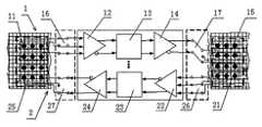
- FIG. 1is a functional diagram of a micro-electronic neural signal regeneration system of some embodiments
- FIG. 2is a diagram of an electrodes system of some embodiments
- FIG. 3is a diagram of amplifier circuits
- FIG. 4is a diagram of a filter of some embodiments.
- Embodiments used to regenerate the sensory, motor or viscus signals of injured nerves of Mammalia including humanare provided, which have the feature of allowing a lineup of downward and upward channels that include a microelectronic system to bridge injured neural channels.
- the downward channelscan be connected to the electrodes which are contacted onto the upper nerve stump (on top of the injured section), to detect, to amplify, and to recognize the motorial signals, to generate the Functional Electrical Stimulation (FES) signals, and to supply the FES signals to the electrodes on the lower nerve stump (below the injured section), so that neural signals can be regenerated and the injured motorial channels can be bridged.
- the upward channelsmay be connected to the detecting electrodes on the lower nerve stump, and after the sensory neural signals are detected and processed, related FES signals are generated to stimulate the upper electrodes, so that the injured sensory channels can be bridged.
- the motorial signalscan be detected by the detecting electrodes, routed by the upper Switching Array (SA), amplified, filtered, and applied to the FES signal generators.
- SASwitching Array
- the FES signalscan then be routed by the lower SA to the stimulating electrodes.
- the sensory signalscan be detected by the detecting electrodes, routed by the lower SA, amplified, filtered, and applied to the FES signal generators.
- the FES signalscan then be routed by the upper SA to the stimulating electrodes of upper sensory nerves.
- the upper and lower SAsmay be used correlatively to make a correct switch among the upper and lower neural channels.
- Equipmentmay be used that includes at least one downward microelectronic channel ( 1 ) and one upward microelectronic channel ( 2 ).
- several ways of microelectronic channelscan be used in parallel in both downward and upward directions. For example, we can choose a 2-way, 4-way or 8-way realization.
- the downward microelectronic channel ( 1 ) mentioned abovemay include motorial signal detecting electrodes ( 11 ), amplifier ( 12 ), signal processor ( 13 ), stimulator ( 14 ), and stimulating electrodes ( 15 ).
- the motorial signals of upper nerve stumpare detected by the detecting electrodes ( 11 ), amplified by the amplifier ( 12 ), processed by the processor ( 13 ), and supplied to the motorial signal stimulator ( 14 ), where the FES signals are generated and applied to the motorial signal stimulating electrodes ( 15 ), so that the desired motorial signals are regenerated in the lower nerve stump.
- the upward microelectronic channel ( 2 ) mentioned abovemay include sensory signal detecting electrodes ( 21 ), amplifier ( 22 ), signal processor ( 23 ), stimulator ( 24 ), and sensory signal stimulating electrodes ( 25 ).
- the sensory signals of lower nerve stumpcan be detected by the detecting electrodes ( 21 ), amplified by the amplifier ( 22 ), processed by the processor ( 23 ), and supplied to sensory signal stimulator ( 24 ), where the FES signals are generated and applied to the sensory signal stimulating electrodes ( 25 ), so that the desired sensory signals are regenerated in the upper nerve stump.
- the contacting electrodes array on upper nerve stumpcan be adopted by both the motorial signal detecting electrodes ( 11 ) and the sensory signal stimulating electrodes ( 25 ).
- the first SA ( 16 and 27 )can be inserted at the place between the contacting electrodes array and the motorial signal amplifier ( 12 ) as well as the sensory signal stimulator ( 24 ).
- the first SA ( 16 and 27 )is used to correctly connect the motorial signal detecting electrodes ( 11 ) to amplifier ( 12 ) and the stimulator ( 24 ) to motorial signal stimulating electrodes ( 25 ).
- the contacting electrodes array on lower nerve stumpcan be adopted by both the motorial signal stimulating electrodes ( 15 ) and the sensory signal detecting electrodes ( 21 ).
- the second SA ( 17 and 26 )can be inserted at the place between the contacting electrodes array on lower nerve stump and the motorial signal stimulator ( 14 ) as well as the sensory signal amplifier ( 22 ). This second SA ( 17 and 26 ) is used to correctly connect the stimulator ( 14 ) to the motorial signal stimulating electrodes ( 15 ) and sensory signal detecting electrodes ( 21 ) to amplifier ( 22 ).
- the signal processor ( 13 and 23 ) mentioned aboveis to recognize the nerve signals and may include an active low pass filter which is made of an RC network and an operational amplifier.
- the amplified signalsare transmitted through the second and third resistor (R 2 , R 3 ) and applied to the in-phase terminal of the operational amplifier ( 31 ).
- the first capacitance (C 1 )is connected across the same in-phase terminal and the ground.
- the first resistor (R 1 )is connected across the anti-phase terminal of the operational amplifier ( 31 ) and the ground.
- the shunt resistor Rfis connected across the anti-phase terminal and the output of the operational amplifier ( 31 ).
- Both the downward neural signal amplifier ( 12 ) and the upward neural signal amplifier ( 22 ) mentioned abovecan include the first, the second amplifier ( 1221 , 1222 or 2221 , 2222 ) and the summing circuit ( 1223 or 2223 ).
- the output terminals of the first and the second amplifier ( 1221 , 1222 or 2221 , 2222 )are connected to the input terminals of the summing circuit ( 1223 or 2223 ).
- the output terminals of the summing circuit ( 1223 or 2223 )are considered as the output terminals of the downward neural signal amplifier ( 12 ) or the upward neural signal amplifier ( 22 ).
- the detecting electrodes ( 11 or 21 )use cuff electrodes.
- the middle oneis connected to the anti-phase terminals of the amplifiers mentioned above, 1221 , 1222 or 2221 , 2222 , while the other two are connected to the in-phase terminals, respectively.
- the function of the neural signal amplifieris to amplify the weak signals detected by the electrodes to a defined amplitude for the further processing.
- both the detecting electrodes and stimulating electrodescan include 3 contacting points, such as, in the same line.
- the 3 pointsbuild up a so-called “tri-polar system”.
- stimulating electrodes2 of them can be taken, for example, the outer two, to build up a differential system.
- the downward motorial detecting electrodes ( 11 ) and the sensory-signal stimulating electrodes 25build up an electrodes array, in which each of the 3 contacting points in a row could be used for either detecting or stimulating of neural signals. This can be dependent on their connecting to motorial or sensory nerve fiber.
- neural signal amplifyingmay be used, such that each neural signal source is equivalent to a weak voltage source with a high resistance.
- the amplitude of the voltage detected from the electrodescan be in the order of microvolt.
- the neural source with a high-resistancecan have a high noise and interference level because of in-body activities.
- An amplifier with a high sensitivitycan be used because neural signals are of a low frequency (400 ⁇ 4000 Hz).
- a high gain, low power operational amplifiercan be designed. Under a supply of 1.8 V, the open-loop gain can be 70.6 dB, the gain-bandwidth-product 3.42 MHz and the power consumption less than 20 ⁇ W.
- neural signal processing techniquescan be used, such as after neural signals have been detected by the electrodes. This may improve signal processing.
- ADCanalog-to-digital converters
- DSPdigital signal processors
- DACdigital-to-analog converters
- ADCanalog-to-digital converters
- DSPdigital signal processors
- DACdigital-to-analog converters
- the architecture of an analog amplifier plus a filterthat is, the traditional analog signal processing, can be used.
- the function of the FES circuitscan be to generate large currents or high voltage FES signals. Taking account of the uncertainty of the input resistance of a one-port network that may include stimulating electrodes and nerve tissue, a constant-current type of FES circuit can be used.
Landscapes
- Health & Medical Sciences (AREA)
- Engineering & Computer Science (AREA)
- Biomedical Technology (AREA)
- Nuclear Medicine, Radiotherapy & Molecular Imaging (AREA)
- Radiology & Medical Imaging (AREA)
- Life Sciences & Earth Sciences (AREA)
- Animal Behavior & Ethology (AREA)
- General Health & Medical Sciences (AREA)
- Public Health (AREA)
- Veterinary Medicine (AREA)
- Measurement And Recording Of Electrical Phenomena And Electrical Characteristics Of The Living Body (AREA)
- Electrotherapy Devices (AREA)
Abstract
Description
Claims (9)
Applications Claiming Priority (4)
| Application Number | Priority Date | Filing Date | Title |
|---|---|---|---|
| CN200510135541 | 2005-12-30 | ||
| CNB2005101355416ACN100444783C (en) | 2005-12-30 | 2005-12-30 | Microelectronic system-assisted neural channel function recovery method and device |
| CN200510135541.6 | 2005-12-30 | ||
| PCT/CN2006/003580WO2007076690A1 (en) | 2005-12-30 | 2006-12-25 | The method and equipment for neural channel bridge aided by a micro-electronic system |
Publications (2)
| Publication Number | Publication Date |
|---|---|
| US20090112286A1 US20090112286A1 (en) | 2009-04-30 |
| US8000806B2true US8000806B2 (en) | 2011-08-16 |
Family
ID=36843425
Family Applications (1)
| Application Number | Title | Priority Date | Filing Date |
|---|---|---|---|
| US12/159,776Expired - Fee RelatedUS8000806B2 (en) | 2005-12-30 | 2006-12-25 | Neural channel bridge aided by a micro-electronic system |
Country Status (3)
| Country | Link |
|---|---|
| US (1) | US8000806B2 (en) |
| CN (1) | CN100444783C (en) |
| WO (1) | WO2007076690A1 (en) |
Families Citing this family (9)
| Publication number | Priority date | Publication date | Assignee | Title |
|---|---|---|---|---|
| CN101349691B (en)* | 2008-09-03 | 2012-05-23 | 东南大学 | Neuron and device for detecting nerve signal transfer characteristic between neuron clusters |
| WO2012064968A1 (en)* | 2010-11-11 | 2012-05-18 | IINN, Inc. | Motor nerve root stimulation |
| WO2013052180A2 (en) | 2011-10-05 | 2013-04-11 | University Of Kansas | Methods and associated neural prosthetic devices for bridging brain areas to improve function |
| CN103245724B (en)* | 2013-05-21 | 2015-10-07 | 东南大学 | The detection method of neurocyte discharge performance under Variable Composition drug effect |
| CN105310679B (en)* | 2015-05-11 | 2018-05-11 | 南京神桥医疗器械有限公司 | Device with nerve/myoelectricity action potential signal record and programming reproducing function |
| US10799152B2 (en)* | 2016-08-11 | 2020-10-13 | Medtronic Xomed, Inc. | System and method for motion detection and accounting |
| CN107212878A (en)* | 2017-07-11 | 2017-09-29 | 唐佩福 | Spinal cord injury bioelectrical signals conduction device |
| CN108926766A (en)* | 2018-08-06 | 2018-12-04 | 南通大学 | A kind of micro stimulator and micro stimulator system |
| CN114588543A (en)* | 2022-04-14 | 2022-06-07 | 广州圣普菲科技有限公司 | A spinal-machine interface for treating spinal cord injury and using method thereof |
Citations (10)
| Publication number | Priority date | Publication date | Assignee | Title |
|---|---|---|---|---|
| US4308868A (en) | 1980-05-27 | 1982-01-05 | The United States Of America As Represented By The Administrator Of The National Aeronautics And Space Administration | Implantable electrical device |
| US4878913A (en)* | 1987-09-04 | 1989-11-07 | Pfizer Hospital Products Group, Inc. | Devices for neural signal transmission |
| US5030225A (en)* | 1987-03-13 | 1991-07-09 | Brown University Research Foundation | Electrically-charged nerve guidance channels |
| US5048522A (en)* | 1990-04-13 | 1991-09-17 | Therapeutic Technologies, Inc. | Power muscle stimulator |
| US5314457A (en) | 1993-04-08 | 1994-05-24 | Jeutter Dean C | Regenerative electrical |
| US5358514A (en) | 1991-12-18 | 1994-10-25 | Alfred E. Mann Foundation For Scientific Research | Implantable microdevice with self-attaching electrodes |
| US5938593A (en)* | 1996-03-12 | 1999-08-17 | Microline Technologies, Inc. | Skin analyzer with speech capability |
| US20050251221A1 (en)* | 2004-05-08 | 2005-11-10 | Bojan Zdravkovic | Neural bridge devices and methods for restoring and modulating neural activity |
| US20060015028A1 (en)* | 1998-10-05 | 2006-01-19 | Advanced Imaging Systems, Inc. | EMG Electrode apparatus and positioning system |
| US20060282127A1 (en)* | 2005-03-24 | 2006-12-14 | Vanderbilt University | Respiratory triggered, bilateral laryngeal stimulator to restore normal ventilation in vocal fold paralysis |
- 2005
- 2005-12-30CNCNB2005101355416Apatent/CN100444783C/enactiveActive
- 2006
- 2006-12-25USUS12/159,776patent/US8000806B2/ennot_activeExpired - Fee Related
- 2006-12-25WOPCT/CN2006/003580patent/WO2007076690A1/enactiveApplication Filing
Patent Citations (11)
| Publication number | Priority date | Publication date | Assignee | Title |
|---|---|---|---|---|
| US4308868A (en) | 1980-05-27 | 1982-01-05 | The United States Of America As Represented By The Administrator Of The National Aeronautics And Space Administration | Implantable electrical device |
| US5030225A (en)* | 1987-03-13 | 1991-07-09 | Brown University Research Foundation | Electrically-charged nerve guidance channels |
| US4878913A (en)* | 1987-09-04 | 1989-11-07 | Pfizer Hospital Products Group, Inc. | Devices for neural signal transmission |
| US5048522A (en)* | 1990-04-13 | 1991-09-17 | Therapeutic Technologies, Inc. | Power muscle stimulator |
| US5358514A (en) | 1991-12-18 | 1994-10-25 | Alfred E. Mann Foundation For Scientific Research | Implantable microdevice with self-attaching electrodes |
| US5314457A (en) | 1993-04-08 | 1994-05-24 | Jeutter Dean C | Regenerative electrical |
| US5938593A (en)* | 1996-03-12 | 1999-08-17 | Microline Technologies, Inc. | Skin analyzer with speech capability |
| US20060015028A1 (en)* | 1998-10-05 | 2006-01-19 | Advanced Imaging Systems, Inc. | EMG Electrode apparatus and positioning system |
| US20050251221A1 (en)* | 2004-05-08 | 2005-11-10 | Bojan Zdravkovic | Neural bridge devices and methods for restoring and modulating neural activity |
| WO2005113062A1 (en) | 2004-05-08 | 2005-12-01 | Bojan Zdravkovic | Neural bridge devices and methods for restoring and modulating neural activity |
| US20060282127A1 (en)* | 2005-03-24 | 2006-12-14 | Vanderbilt University | Respiratory triggered, bilateral laryngeal stimulator to restore normal ventilation in vocal fold paralysis |
Also Published As
| Publication number | Publication date |
|---|---|
| WO2007076690A1 (en) | 2007-07-12 |
| CN100444783C (en) | 2008-12-24 |
| CN1810203A (en) | 2006-08-02 |
| US20090112286A1 (en) | 2009-04-30 |
Similar Documents
| Publication | Publication Date | Title |
|---|---|---|
| US8000806B2 (en) | Neural channel bridge aided by a micro-electronic system | |
| US11944439B2 (en) | Method and system for controlling electrical conditions of tissue | |
| Chandrakumar et al. | A high dynamic-range neural recording chopper amplifier for simultaneous neural recording and stimulation | |
| Rieger et al. | Design of a low-noise preamplifier for nerve cuff electrode recording | |
| Samiei et al. | A bidirectional neural interface SoC with adaptive IIR stimulation artifact cancelers | |
| US20100280577A1 (en) | Implantable pulse generator | |
| US20160016006A1 (en) | Method and system for cochlea stimulation | |
| Nag et al. | Sensing of stimulus artifact suppressed signals from electrode interfaces | |
| Xu et al. | A bionic neural link for peripheral nerve repair | |
| Habibollahi et al. | Active neural interface circuits and systems for selective control of peripheral nerves: a review | |
| CN117899359A (en) | Two-step charge recovery circuit and method for neural stimulator | |
| US11116982B2 (en) | Implanted medical device for use in treating arrhythmia | |
| CN113332011B (en) | Electric stimulation interference removal system and method for myoelectric artificial limb | |
| Wang et al. | Microelectronics-embedded channel bridging and signal regeneration of injured spinal cords | |
| Liu et al. | An artifact-suppressed stimulator for simultaneous neural recording and stimulation systems | |
| Cuevas et al. | Toward the Optimal Architecture of an ASIC for Neurostimulation. | |
| Zhang et al. | A neural recording ic design with on-chip CMOS electrode array for brain-machine interface | |
| WO2013029618A1 (en) | A system for recording and processing neural activity | |
| US6636770B2 (en) | Single-path lead for an active implantable medical device of the implantable defibrillator/cardiovertor type | |
| Micera et al. | Experiments on the development and use of a new generation of intra-neural electrodes to control robotic devices | |
| 沈晓燕 et al. | Microelectronic neural bridge for signal regeneration and function rebuilding over two separate nerves | |
| Bugbee | An implantable stimulator for selective stimulation of nerves | |
| JPH05293187A (en) | Electric stimulating device | |
| Chen et al. | A simultaneous neural recording and stimulation system using signal folding in recording circuits | |
| RU2059402C1 (en) | Device for bioelectrical operating of muscles |
Legal Events
| Date | Code | Title | Description |
|---|---|---|---|
| AS | Assignment | Owner name:SOUTHEAST UNIVERSITY, CHINA Free format text:ASSIGNMENT OF ASSIGNORS INTEREST;ASSIGNORS:WANG, ZHIGONG;GU, XIAOSONG;LV, XIAOYING;REEL/FRAME:021703/0842;SIGNING DATES FROM 20080901 TO 20080902 Owner name:NANTONG UNIVERSITY, CHINA Free format text:ASSIGNMENT OF ASSIGNORS INTEREST;ASSIGNORS:WANG, ZHIGONG;GU, XIAOSONG;LV, XIAOYING;REEL/FRAME:021703/0842;SIGNING DATES FROM 20080901 TO 20080902 Owner name:SOUTHEAST UNIVERSITY, CHINA Free format text:ASSIGNMENT OF ASSIGNORS INTEREST;ASSIGNORS:WANG, ZHIGONG;GU, XIAOSONG;LV, XIAOYING;SIGNING DATES FROM 20080901 TO 20080902;REEL/FRAME:021703/0842 Owner name:NANTONG UNIVERSITY, CHINA Free format text:ASSIGNMENT OF ASSIGNORS INTEREST;ASSIGNORS:WANG, ZHIGONG;GU, XIAOSONG;LV, XIAOYING;SIGNING DATES FROM 20080901 TO 20080902;REEL/FRAME:021703/0842 | |
| STCF | Information on status: patent grant | Free format text:PATENTED CASE | |
| FEPP | Fee payment procedure | Free format text:PAYOR NUMBER ASSIGNED (ORIGINAL EVENT CODE: ASPN); ENTITY STATUS OF PATENT OWNER: SMALL ENTITY | |
| FPAY | Fee payment | Year of fee payment:4 | |
| FEPP | Fee payment procedure | Free format text:MAINTENANCE FEE REMINDER MAILED (ORIGINAL EVENT CODE: REM.); ENTITY STATUS OF PATENT OWNER: SMALL ENTITY | |
| LAPS | Lapse for failure to pay maintenance fees | Free format text:PATENT EXPIRED FOR FAILURE TO PAY MAINTENANCE FEES (ORIGINAL EVENT CODE: EXP.); ENTITY STATUS OF PATENT OWNER: SMALL ENTITY | |
| STCH | Information on status: patent discontinuation | Free format text:PATENT EXPIRED DUE TO NONPAYMENT OF MAINTENANCE FEES UNDER 37 CFR 1.362 | |
| FP | Lapsed due to failure to pay maintenance fee | Effective date:20190816 |