US8000774B2 - Method and system for intra luminal thrombus detection - Google Patents
Method and system for intra luminal thrombus detectionDownload PDFInfo
- Publication number
- US8000774B2 US8000774B2US11/619,387US61938707AUS8000774B2US 8000774 B2US8000774 B2US 8000774B2US 61938707 AUS61938707 AUS 61938707AUS 8000774 B2US8000774 B2US 8000774B2
- Authority
- US
- United States
- Prior art keywords
- spectral responses
- spectral
- responses
- regions
- vessel
- Prior art date
- Legal status (The legal status is an assumption and is not a legal conclusion. Google has not performed a legal analysis and makes no representation as to the accuracy of the status listed.)
- Active, expires
Links
Images


Classifications
- A—HUMAN NECESSITIES
- A61—MEDICAL OR VETERINARY SCIENCE; HYGIENE
- A61B—DIAGNOSIS; SURGERY; IDENTIFICATION
- A61B5/00—Measuring for diagnostic purposes; Identification of persons
- A61B5/0059—Measuring for diagnostic purposes; Identification of persons using light, e.g. diagnosis by transillumination, diascopy, fluorescence
- A61B5/0075—Measuring for diagnostic purposes; Identification of persons using light, e.g. diagnosis by transillumination, diascopy, fluorescence by spectroscopy, i.e. measuring spectra, e.g. Raman spectroscopy, infrared absorption spectroscopy
- A—HUMAN NECESSITIES
- A61—MEDICAL OR VETERINARY SCIENCE; HYGIENE
- A61B—DIAGNOSIS; SURGERY; IDENTIFICATION
- A61B5/00—Measuring for diagnostic purposes; Identification of persons
- A61B5/0059—Measuring for diagnostic purposes; Identification of persons using light, e.g. diagnosis by transillumination, diascopy, fluorescence
- A61B5/0082—Measuring for diagnostic purposes; Identification of persons using light, e.g. diagnosis by transillumination, diascopy, fluorescence adapted for particular medical purposes
- A61B5/0084—Measuring for diagnostic purposes; Identification of persons using light, e.g. diagnosis by transillumination, diascopy, fluorescence adapted for particular medical purposes for introduction into the body, e.g. by catheters
- A61B5/0086—Measuring for diagnostic purposes; Identification of persons using light, e.g. diagnosis by transillumination, diascopy, fluorescence adapted for particular medical purposes for introduction into the body, e.g. by catheters using infrared radiation
- A—HUMAN NECESSITIES
- A61—MEDICAL OR VETERINARY SCIENCE; HYGIENE
- A61B—DIAGNOSIS; SURGERY; IDENTIFICATION
- A61B5/00—Measuring for diagnostic purposes; Identification of persons
- A61B5/02—Detecting, measuring or recording for evaluating the cardiovascular system, e.g. pulse, heart rate, blood pressure or blood flow
- A61B5/02007—Evaluating blood vessel condition, e.g. elasticity, compliance
- G—PHYSICS
- G01—MEASURING; TESTING
- G01J—MEASUREMENT OF INTENSITY, VELOCITY, SPECTRAL CONTENT, POLARISATION, PHASE OR PULSE CHARACTERISTICS OF INFRARED, VISIBLE OR ULTRAVIOLET LIGHT; COLORIMETRY; RADIATION PYROMETRY
- G01J3/00—Spectrometry; Spectrophotometry; Monochromators; Measuring colours
- G01J3/28—Investigating the spectrum
- G01J3/42—Absorption spectrometry; Double beam spectrometry; Flicker spectrometry; Reflection spectrometry
- G—PHYSICS
- G01—MEASURING; TESTING
- G01N—INVESTIGATING OR ANALYSING MATERIALS BY DETERMINING THEIR CHEMICAL OR PHYSICAL PROPERTIES
- G01N21/00—Investigating or analysing materials by the use of optical means, i.e. using sub-millimetre waves, infrared, visible or ultraviolet light
- G01N21/17—Systems in which incident light is modified in accordance with the properties of the material investigated
- G01N21/25—Colour; Spectral properties, i.e. comparison of effect of material on the light at two or more different wavelengths or wavelength bands
- G01N21/31—Investigating relative effect of material at wavelengths characteristic of specific elements or molecules, e.g. atomic absorption spectrometry
- G01N21/35—Investigating relative effect of material at wavelengths characteristic of specific elements or molecules, e.g. atomic absorption spectrometry using infrared light
- G01N21/359—Investigating relative effect of material at wavelengths characteristic of specific elements or molecules, e.g. atomic absorption spectrometry using infrared light using near infrared light
Definitions
- Intra luminal spectroscopic analysis deviceshave been developed and commercialized.
- One applicationconcerns the assessment of the state of blood vessel walls such as required in the diagnosis of atherosclerosis.
- Thisis an arterial disorder involving the intimae of medium- or large-sized arteries, including the aortic, carotid, coronary, and cerebral arteries.
- Atherosclerotic lesions or plaquescan contain complex tissue matrices, including collagen, elastin, proteoglycans, and extracellular and intracellular lipids with foamy macrophages and smooth muscle cells.
- inflammatory cellular componentse.g., T lymphocytes, macrophages, and some basophiles
- T lymphocytese.g., T lymphocytes, macrophages, and some basophiles
- the intra luminal spectroscopic analysis devicesare used to extract information concerning the state of the vessels walls from the generated spectral information.
- Mathematical and statistical manipulationssuch as linear and non-linear regressions of the spectral band of interest and other multivariate analysis tools are available for building quantitative calibrations as well as qualitative models for discriminant analysis, enabling the detection and characterization of any vascular lesions.
- One specific intra luminal spectroscopic analysis deviceuses an optical source, such as a tunable laser, to access or scan a spectral band of interest, such as a scan band in the near infrared of 750 nanometers (nm) to 2.5 micrometers ( ⁇ m).
- a spectral band of interestsuch as a scan band in the near infrared of 750 nanometers (nm) to 2.5 micrometers ( ⁇ m).
- the generated lightis used to illuminate tissue in a target area in vivo using a catheter. Diffusely reflected light resulting from the illumination is then collected and transmitted to a detector system, where a spectral response is resolved.
- This intra luminal spectroscopic deviceactually builds a “color picture” of the inner walls of the blood vessel. This is accomplished by rotating the head of the catheter while drawing the head through the region of interest of the vessel. This produces the spectral response within the scan band of the tunable laser for a series of points along a helical path across the vessels walls. These points are aligned into a raster image of the vessel wall for the region of interest.
- a thrombus or blood clotis a product of coagulation within a blood vessel and typically appears as a semisolid mass, with the thrombus impeding or blocking the flow of blood through the vessel. Typically it includes platelets, red blood cells, white blood cells and/or fibrin.
- Thrombosisi.e., the formation or presence of a clot or thrombus, can be caused by infection, trauma, injury, a slowing down or stagnation of blood flow past a point of injury, or rupture of an atherosclerotic plaque.
- a coronary thrombusoften initially forms at the site of rupture of a vulnerable plaque; i.e. at the location of a plaque with a lipid-rich core and a thin fibrous cap (thin-cap fibroatheroma or TCFA).
- TCFAthin fibrous cap
- the inventiongenerally relates to detecting a complete or partial obstruction in a vessel through an intervening fluid.
- the obstructionis a thrombus.
- In vivo location of a thrombusis useful during diagnosis, in monitoring response to medication, and in surgical procedures.
- locating a thrombusincludes receiving spectroscopic responses of a vessel wall, e.g., a vein or artery, through an intervening fluid, preferably blood.
- a vessel walle.g., a vein or artery
- an intervening fluidpreferably blood.
- Saline solution or another suitable fluidalso can be employed.
- Spectroscopic responsesare generated by irradiating the vessel wall at different locations and detecting spectra at those locations.
- the radiation usedis in the near infrared (NIR) region of the electromagnetic spectrum.
- NIRrefers to electromagnetic radiation in the wavelength region of about 700 nanometers (nm) to about 3000 nm.
- the spectral responseis first acquired for a full spectral region and then bands selected within the full spectral region for further analysis.
- NIRcan be generated by a tunable laser.
- the inventionfeatures a method for locating a vascular obstruction.
- the methodcomprises determining spectroscopic responses within different regions of a wall of a vessel through an intervening fluid and analyzing spatial fluctuations in the spectral responses in the different regions. Any vascular obstruction is then located to one or more of the regions based on the spatial fluctuations in the spectral responses.
- the step of determining the spectroscopic responsescomprises irradiating the different regions with a near infrared source and detecting diffuse reflectance spectra within the different regions. Also, the step of determining the spectroscopic responses comprises irradiating the different regions with a near infrared source and detecting absorption spectra within the different regions.
- a catheteris inserted into the vessel, which is irradiated via a head of the catheter. The returning light is detected while rotating the head within the vessels and drawing the head through the vessel to generate a helical raster scan.
- the step of analyzing the spatial fluctuationsfurther comprises determining regions in which the spatial fluctuations of the spectral response exceed a threshold, possibly in a narrowed wavelength band, such as one in which lipids have strong reflectance.
- the inventionfeatures device for locating vascular obstructions.
- This devicecomprises an optical catheter that is inserted into a blood vessel and a spectrometer for generating light into and receiving light from the optical catheter to resolve spectral responses of walls of the blood vessel.
- An analyzerreceives the spectral responses and searches for regions of the walls of the blood vessels that exhibit spatial fluctuations in the spectral responses to locate vascular obstructions to the regions based on the spatial fluctuations in the spectral responses.
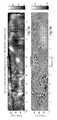
- FIGS. 1 a and 1 bshow a reflectance image and an absorption image, respectively, generated by the near infrared (NIR) scanning of the inside of a blood vessel covering a pullback distance of 0 to 55 millimeters and an angular range of 0 to 360 degrees;
- NIRnear infrared
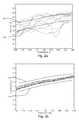
- FIGS. 2 a and 2 bare plots of absorbance as a function of wavelength for various pixels within regions 150 and 154 , respectively, in FIG. 1 b;
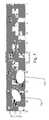
- FIGS. 3 a and 3 billustrate a device for detecting and analyzing the spectral responses of the vessel walls including detection of thrombus according to the invention
- FIG. 4is a flow diagram showing a method for detecting thrombus according to the present invention.
- FIGS. 5 a and 5 bshow a reflectance image and an absorption image, respectively, generated by the near infrared (NIR) scanning of the inside of a blood vessel through flowing blood for another blood vessel;
- NIRnear infrared
- FIGS. 6 a and 6 bshow a reflectance image and an absorption image, respectively, generated by the near infrared (NIR) scanning of the inside of a blood vessel for stagnant blood for the blood vessel used in the generation of the data in FIGS. 5 a and 5 b ; and
- NIRnear infrared
- FIG. 7is a false color absorption image highlighting potential thrombi.
- FIGS. 1 a and 1 bshow a reflectance image and an absorption image generated by the near infrared (NIR) scanning of the inside of a blood vessel. These spectral measurements were collected through flowing blood.
- NIRnear infrared
- the guide wire 152can be seen as a dark shadow across the mean reflectance pullback image in FIG. 1 a .
- an average of the reflectance spectrum across the full wavelength rangeis taken for each pixel.
- each pixel in the imageis the average intensity of the reflectance spectrum at that point.
- FIG. 1 bis notable because it shows a distinct mottled pattern in regions including region 150 in the peak absorbance image at a pull back distance of approximately 40-55 millimeters corresponding to the location of an obstruction, such as a clot or thrombus.
- the absorption imageis referred to as “peak absorbance” because here the average of each pixel is taken across a limited wavelength range (1200-1240 nm) where lipids have a strong absorbance signal or peak. The average here can be thought of an approximate area under the peak since it is taken after a linear baseline correction.
- FIGS. 2 a and 2 bfurther characterize the differences between the mottled region 150 at 42-45 millimeters and 275 to 300 degrees in FIG. 1 b and the typical spectral characteristics of the vessel walls such as exemplified in pullback region 15-18 millimeters and angle 275 to 300 degrees in FIG. 1 b .
- the mottled spectra of the thrombushave significantly different characteristics from the spectra taken from the normal regions.
- the absorbance as a function of wavelength for various pixels within mottled region 150is plotted in FIG. 2 a . It shows a high degree of variation or spectral and spatial fluctuation in the spectral responses.
- each plotted pixel in FIG. 2 aexhibits large “intra-pixel” variation in its spectral response over the 1180 to 1260 spectral band that is plotted. That is, each line in FIG. 2 a shows large departures from an average response.
- FIG. 2 aexhibits a large “inter-pixel” variation in that the spectral responses for the various pixels are very different from each other with a low degree of inter-pixel correlation.
- the intra-pixel and inter-pixel variation of FIG. 2 ais in contrast to pixels of region 154 plotted in FIG. 2 b .
- the spectral response of each pixelis very smooth, almost linear over the 1180-1260 scan band, a low degree of intra-pixel spectral variation over the scan band.
- the spectral responses of the plotted pixelsare very similar to each other, a low degree of inter-pixel variation.
- the absorbance as a function of wavelength for individual pixels and/or pixels within a regionare compared to an average absorbance at each wavelength, and specifically an upper threshold 156 and a lower threshold 158 , which are set based on the calculated average absorbance.
- an upper threshold 156 and a lower threshold 158which are set based on the calculated average absorbance.
- a fixed-size rectangular window(pullback position range in millimeters and angular position range in degrees) is sequentially moved along the longitudinal and rotational angle directions of the pullback.
- absorbance spectra corresponding to the locations within the windoware averaged to give a single mean absorbance spectrum.
- An nth order polynomial functionis then fitted to the mean absorbance spectrum and the absorbance difference at each wavelength between the measured and fitted spectrum is computed.
- a score for the windowis determined by calculating the root mean square (RMS) of the absorbance differences.
- the windowis then translated by a fixed amount and the scoring process repeated. Scores are thus computed for each window position across the pullback. Regions with high scores are said to be mottled and potential areas of thrombus.
- pixelsare sequentially selected. For each pixel, nth, such as 1 st or 2 nd , order polynomial function is fitted to the absorbance spectrum for the pixels and the absorbance difference at each wavelength between the measured and fitted spectrum is computed. A score for the pixel is determined by calculating the root mean square (RMS) of the absorbance differences. Based on a single pixel score or the scores of a group of adjacent pixels, individual pixels or groups of pixels with high scores are said to be mottled and potential areas of thrombus.
- RMSroot mean square
- FIGS. 3 a and 3 billustrate an exemplary device for detecting and analyzing the spectral responses of the vessel walls.
- the devicegenerally comprises a catheter 56 , a controller 40 , and analyzer 42 .
- the catheter 56includes the optical fiber bundle.
- the catheter 56is typically inserted into the patient 2 via a peripheral vessel, such as the femoral artery 10 .
- the catheter head 58is then moved to a desired target area, such as a coronary artery 18 of the heart 16 or the carotid artery 14 . In the embodiment, this is achieved by moving the catheter head 58 up through the aorta 12 .
- the catheterrides on a guide wire that is first advanced through the patient's blood vessels.
- optical radiationis generated, preferably by a tunable source 44 , such as a semiconductor tunable laser, and tuned over a range covering one or more spectral bands of interest.
- a tunable source 44such as a semiconductor tunable laser
- one or more broadband sourcesare used to access the spectral bands of interest.
- the optical signalsare coupled into the single mode fibers of the catheter 56 to be transmitted to the catheter head 58 .
- optical radiation in the near infrared (NIR) spectral regionsis used for spectroscopy.
- Exemplary scan bandsinclude 1000 to 1450 nanometers (nm) generally, or 1000 nm to 1350 nm, 1150 nm to 1250 nm, 1175 nm to 1280 nm, and 1190 nm to 1250 nm, more specifically.
- Other exemplary scan bandsinclude 1660 nm to 1740 nm, and 1630 nm to 1800 nm.
- scan bands appropriate for fluorescence and/or Raman spectroscopyare used.
- scan bands in the visible or ultraviolet regionsare selected.
- the returning lightis transmitted back down multimode optical fibers of the catheter 56 .
- the returning radiationis provided to a detector system 52 , which can comprise one or multiple detectors.
- a spectrometer controller 60monitors the response of the detector system 52 , while controlling the source or tunable laser 44 in order to probe the spectral response of a target area, typically on an inner wall of a blood vessel and through the intervening blood or other unwanted signal source, which is typically a fluid, such as a saline flush.
- the spectrometer controller 60is able to collect spectra. When the acquisition of the spectra is complete, the spectrometer controller 60 then provides the data to the analyzer 42 .
- the optical signal of the tunable laser 44is carried by fiber bundle 102 and directed by the side firing termination 62 , to exit from the catheter head 58 through window 48 and impinge on the target area 22 of the artery wall 24 .
- the catheter head 58collects the light that has been diffusely reflected or refracted (scattered) from the target area 22 and the intervening fluid 108 through window 48 and returns the light in bundle 102 back down the catheter 56 through the multimode fibers to the detector system 52 .
- the catheter head 58spins as illustrated by arrow 110 .
- the head 58is pulled back in direction of arrow 112 .
- This combined rotation and longitudinal movementallow a portion or section of the vessel to be analyzed by creating a helical raster scan of the inner vessel walls.
- the movement 110 , 112 of the catheter head 58is driven by a pullback and rotation unit 54 that draws the catheter head 58 longitudinally through the vessel such as the coronary or carotid artery, and also drives the catheter head 58 to rotate within that vessel.
- the analyzer 42makes an assessment of the state of the blood vessel walls 24 , which is presented to the operator via interface 70 .
- the collected spectral responseis used to determine whether each region of interest 22 of the blood vessel wall 24 comprises a lipid pool or lipid-rich atheroma, a disrupted plaque, a vulnerable plaque or thin-cap fibroatheroma (TCFA), a fibrotic lesion, a calcific lesion, and/or normal tissue.
- Each region 22is also analyzed for the presence of an obstruction, such as thrombosis in the current application. This categorized or even quantified information is provided to an operator via a user interface 70 , or the raw collected spectral images are provided to the operator, who then makes the conclusion as to the state of the region of interest 22 .
- the analyzer 42searches for pixels, groups of pixels, or pixels within regions of the vessel walls that exhibit spatial fluctuations in the spectral responses and specifically those regions in which the spatial fluctuations of the spectral response fall outside thresholds 156 and/or 158 . By identifying these regions, the analyzer 42 locates any thrombi or presents the images including the peak absorbance images to the operator, who then finds the spatial fluctuations indicative of thrombi.
- FIG. 4is a flow diagram illustrating a process for detecting thrombus in the blood vessels.
- step 410the catheter 56 is inserted into the vessel 14 , 18 of interest. Then, the pullback and rotation unit 54 drives the catheter head 58 to rotate within the vessel while the head 58 is drawn through the vessel in step 412 . This produces the helical scans and specifically the NIR spectra of the inner walls.
- step 414the helical scans are compiled into images that define regions relative to angular position, i.e., the angular position of the head, and the longitudinal position of the head, during the scan. This produces the images as shown in FIGS. 1 a and 1 b.
- a first processing step 416the spectra are analyzed to remove any artifacts introduced by instrument operation. Specifically, data associated with improper operation of the instrument are removed as being data acquisition errors.
- step 418a dark count estimation and subtraction is performed on the image. Specifically, an estimation of the dark count for each scan is determined and subtracted from the collected spectra.
- step 420the reflectance and absorbance spectra are generated. These are generated by calculating the ratio of the dark count corrected signal and a reference spectra.
- the collected spectraare then low pass filtered at a 2 nanometer resolution in step 422 .
- end regions of the scani.e., data generated initially during the pullback and/or near the end of the pullback are excluded at the extremes of the pullback as being outside the area of interest.
- end regions of the scani.e., data generated initially during the pullback and/or near the end of the pullback are excluded at the extremes of the pullback as being outside the area of interest.
- only the proximal end of the pullbackis excluded in vivo, and even then only if the catheter head was pulled into the guide catheter.
- data corresponding to regions outside of the area of intereste.g. guide catheter, are excluded.
- Mean reflectance and absorbance peak areasare computed in step 426 . Specifically, for the entire scans, the mean reflectance across the full wavelength region (1180-1260 nanometers) and the area under the base-line corrected absorbance peak between 1200 and 1240 nanometers are calculated. Then, based upon these mean and standard deviation calculations and also possibly averages, the thresholds 156 , 158 or curve fits are determined and the images are analyzed to find pixels or regions such as region 150 where there are high levels of intra-pixel or spatial fluctuation in the spectral responses in step 428 . These regions are then further analyzed for the existence of a thrombus.
- FIGS. 5 a and 5 bshow reflectance and absorption spectra from a pullback through a human coronary artery.
- FIG. 5 ashows the mean reflectance as a function of rotation angle and pullback distance.
- FIG. 5 bshows peak absorbance area (1200-1240 nm) as a function of rotation angle and pullback distance.
- Spectral measurementsare collected through flowing human blood. Thrombus image features are seen at a pullback distance between 34 and 49 millimeters in absorbance image of FIG. 5 b.
- FIGS. 6 a and 6 bshow the reflectance and absorption spectra for the same human coronary artery used to produce FIGS. 5 a and 5 b .
- FIG. 6 ashows the mean reflectance as a function of rotation angle and pullback distance.
- FIG. 6 bshows peak absorbance area (1200-1240 nm) as a function of rotation angle and pullback distance. Spectral measurements were collected through stagnant human blood. Thrombus image features are no longer seen at a pullback distance between 34 and 44 mm in absorbance image of FIG. 6 b . These data suggest that the mottling in the spectral images associated with thrombus area is related to interaction of the obstruction and the flowing blood.
- the thrombusmay act as an obstruction that causes eddies in the flow, thereby altering the NIR scattering properties of the blood.
- the thrombusmay be subject to a fluttering motion by the flow of blood, causing a rapidly varying NIR scattering surface.
- the analysisshows that the NIR absorbance measured through flowing blood produced a distinctive mottled pattern that correlated with the presence of thrombus in the vessel wall. The pattern was not visible when blood flow through the vessel was stopped, suggesting that the thrombus has a physical effect on light scatter that is detectable.
- FIG. 7illustrates one example of an image provided on the display device of the user interface 70 . This is processed absorption spectra in which areas of potential thrombi are identified as described in FIG. 4 , for example. These regions are then highlighted with false color 710 in order to convey the result of the thrombus detection to the operator.
Landscapes
- Health & Medical Sciences (AREA)
- Life Sciences & Earth Sciences (AREA)
- Physics & Mathematics (AREA)
- Spectroscopy & Molecular Physics (AREA)
- Molecular Biology (AREA)
- General Health & Medical Sciences (AREA)
- Engineering & Computer Science (AREA)
- Biomedical Technology (AREA)
- Heart & Thoracic Surgery (AREA)
- Medical Informatics (AREA)
- Biophysics (AREA)
- Surgery (AREA)
- Animal Behavior & Ethology (AREA)
- Pathology (AREA)
- Public Health (AREA)
- Veterinary Medicine (AREA)
- Vascular Medicine (AREA)
- Cardiology (AREA)
- Physiology (AREA)
- General Physics & Mathematics (AREA)
- Endoscopes (AREA)
- Investigating Or Analysing Materials By Optical Means (AREA)
Abstract
Description
Claims (16)
Priority Applications (2)
| Application Number | Priority Date | Filing Date | Title |
|---|---|---|---|
| US11/619,387US8000774B2 (en) | 2007-01-03 | 2007-01-03 | Method and system for intra luminal thrombus detection |
| PCT/US2007/084416WO2008082800A1 (en) | 2007-01-03 | 2007-11-12 | Method and system for intra luminal thrombus detection |
Applications Claiming Priority (1)
| Application Number | Priority Date | Filing Date | Title |
|---|---|---|---|
| US11/619,387US8000774B2 (en) | 2007-01-03 | 2007-01-03 | Method and system for intra luminal thrombus detection |
Publications (2)
| Publication Number | Publication Date |
|---|---|
| US20080161698A1 US20080161698A1 (en) | 2008-07-03 |
| US8000774B2true US8000774B2 (en) | 2011-08-16 |
Family
ID=39167762
Family Applications (1)
| Application Number | Title | Priority Date | Filing Date |
|---|---|---|---|
| US11/619,387Active2027-07-20US8000774B2 (en) | 2007-01-03 | 2007-01-03 | Method and system for intra luminal thrombus detection |
Country Status (2)
| Country | Link |
|---|---|
| US (1) | US8000774B2 (en) |
| WO (1) | WO2008082800A1 (en) |
Cited By (4)
| Publication number | Priority date | Publication date | Assignee | Title |
|---|---|---|---|---|
| US20090312644A1 (en)* | 2008-06-11 | 2009-12-17 | Sumitomo Electric Industries, Ltd | Vital tissue discrimination device and method |
| US20110098560A1 (en)* | 2009-10-23 | 2011-04-28 | Canon Kabushiki Kaisha | Optical tomographic image generating apparatus and optical tomographic image generating method |
| US20130053698A1 (en)* | 2011-08-29 | 2013-02-28 | Infraredx, Inc. | Detection of lipid core plaque cap thickness |
| US10776654B2 (en) | 2015-03-10 | 2020-09-15 | Infraredx, Inc. | Assessment of lipid core plaque integrity |
Families Citing this family (9)
| Publication number | Priority date | Publication date | Assignee | Title |
|---|---|---|---|---|
| US8636670B2 (en) | 2008-05-13 | 2014-01-28 | The Invention Science Fund I, Llc | Circulatory monitoring systems and methods |
| US9672471B2 (en)* | 2007-12-18 | 2017-06-06 | Gearbox Llc | Systems, devices, and methods for detecting occlusions in a biological subject including spectral learning |
| US8280484B2 (en) | 2007-12-18 | 2012-10-02 | The Invention Science Fund I, Llc | System, devices, and methods for detecting occlusions in a biological subject |
| US9717896B2 (en) | 2007-12-18 | 2017-08-01 | Gearbox, Llc | Treatment indications informed by a priori implant information |
| US20090287120A1 (en) | 2007-12-18 | 2009-11-19 | Searete Llc, A Limited Liability Corporation Of The State Of Delaware | Circulatory monitoring systems and methods |
| US11026591B2 (en)* | 2013-03-13 | 2021-06-08 | Philips Image Guided Therapy Corporation | Intravascular pressure sensor calibration |
| WO2017173351A1 (en)* | 2016-03-31 | 2017-10-05 | Designplex Biomedical, Llc | Vascular monitoring system |
| EP3573514A1 (en)* | 2017-01-24 | 2019-12-04 | Koninklijke Philips N.V. | Device for determining information relating to a suspected occluding object |
| US20200359901A1 (en)* | 2017-08-18 | 2020-11-19 | Vena Medical Holdings Corp. | Device and method for imaging vasculature |
Citations (14)
| Publication number | Priority date | Publication date | Assignee | Title |
|---|---|---|---|---|
| US6394956B1 (en)* | 2000-02-29 | 2002-05-28 | Scimed Life Systems, Inc. | RF ablation and ultrasound catheter for crossing chronic total occlusions |
| US6485413B1 (en)* | 1991-04-29 | 2002-11-26 | The General Hospital Corporation | Methods and apparatus for forward-directed optical scanning instruments |
| US20020177777A1 (en)* | 1998-12-23 | 2002-11-28 | Medispectra, Inc. | Optical methods and systems for rapid screening of the cervix |
| US20020183601A1 (en) | 2000-10-30 | 2002-12-05 | Tearney Guillermo J. | Optical methods and systems for tissue analysis |
| US20030028100A1 (en)* | 2001-05-01 | 2003-02-06 | Tearney Guillermo J. | Method and apparatus for determination of atherosclerotic plaque type by measurement of tissue optical properties |
| US20030055307A1 (en)* | 2001-06-04 | 2003-03-20 | David Elmaleh | Devices for detection and therapy of atheromatous plaque |
| WO2004012586A2 (en) | 2002-08-05 | 2004-02-12 | Infraredx, Inc. | Near-infrared spectroscopic analysis of blood vessel walls |
| US20040073120A1 (en)* | 2002-04-05 | 2004-04-15 | Massachusetts Institute Of Technology | Systems and methods for spectroscopy of biological tissue |
| US20050043637A1 (en) | 2003-08-22 | 2005-02-24 | Infraredx, Inc. | Method and system for spectral examination of vascular walls through blood during cardiac motion |
| US6890332B2 (en)* | 1999-05-24 | 2005-05-10 | Csaba Truckai | Electrical discharge devices and techniques for medical procedures |
| WO2005096921A1 (en) | 2004-04-01 | 2005-10-20 | Infraredx, Inc. | Method and system for dual domain discrimination of vulnerable plaque |
| US20060041199A1 (en)* | 2004-06-18 | 2006-02-23 | Elmaleh David R | Intravascular imaging device and uses thereof |
| US20070038124A1 (en)* | 2005-06-02 | 2007-02-15 | Newton Laboratories, Inc. | Optical probe for arterial tissue analysis |
| US7208190B2 (en)* | 2002-11-07 | 2007-04-24 | Abbott Laboratories | Method of loading beneficial agent to a prosthesis by fluid-jet application |
- 2007
- 2007-01-03USUS11/619,387patent/US8000774B2/enactiveActive
- 2007-11-12WOPCT/US2007/084416patent/WO2008082800A1/enactiveApplication Filing
Patent Citations (15)
| Publication number | Priority date | Publication date | Assignee | Title |
|---|---|---|---|---|
| US6485413B1 (en)* | 1991-04-29 | 2002-11-26 | The General Hospital Corporation | Methods and apparatus for forward-directed optical scanning instruments |
| US20020177777A1 (en)* | 1998-12-23 | 2002-11-28 | Medispectra, Inc. | Optical methods and systems for rapid screening of the cervix |
| US6890332B2 (en)* | 1999-05-24 | 2005-05-10 | Csaba Truckai | Electrical discharge devices and techniques for medical procedures |
| US6394956B1 (en)* | 2000-02-29 | 2002-05-28 | Scimed Life Systems, Inc. | RF ablation and ultrasound catheter for crossing chronic total occlusions |
| US20020183601A1 (en) | 2000-10-30 | 2002-12-05 | Tearney Guillermo J. | Optical methods and systems for tissue analysis |
| US20030028100A1 (en)* | 2001-05-01 | 2003-02-06 | Tearney Guillermo J. | Method and apparatus for determination of atherosclerotic plaque type by measurement of tissue optical properties |
| US20030055307A1 (en)* | 2001-06-04 | 2003-03-20 | David Elmaleh | Devices for detection and therapy of atheromatous plaque |
| US20070258906A1 (en)* | 2001-06-04 | 2007-11-08 | Fischman Alan J | Methods and devices for detection and therapy of atheromatous plaque |
| US20040073120A1 (en)* | 2002-04-05 | 2004-04-15 | Massachusetts Institute Of Technology | Systems and methods for spectroscopy of biological tissue |
| WO2004012586A2 (en) | 2002-08-05 | 2004-02-12 | Infraredx, Inc. | Near-infrared spectroscopic analysis of blood vessel walls |
| US7208190B2 (en)* | 2002-11-07 | 2007-04-24 | Abbott Laboratories | Method of loading beneficial agent to a prosthesis by fluid-jet application |
| US20050043637A1 (en) | 2003-08-22 | 2005-02-24 | Infraredx, Inc. | Method and system for spectral examination of vascular walls through blood during cardiac motion |
| WO2005096921A1 (en) | 2004-04-01 | 2005-10-20 | Infraredx, Inc. | Method and system for dual domain discrimination of vulnerable plaque |
| US20060041199A1 (en)* | 2004-06-18 | 2006-02-23 | Elmaleh David R | Intravascular imaging device and uses thereof |
| US20070038124A1 (en)* | 2005-06-02 | 2007-02-15 | Newton Laboratories, Inc. | Optical probe for arterial tissue analysis |
Non-Patent Citations (6)
| Title |
|---|
| "MGH and CIMIT Researchers Use Laser Light to Identify Atherosclerotic Plaques That Cause Heart Attacks," Healthcare Sales & Marketing Network NewsFeed, http://www.salesandmarketingnetwork.com/news-release.php?ID=2006424&key=laser, 2 pages, News Release, Aug. 1, 2005. |
| Caplan, Jay D., et al., "Near-Infarared Spectroscopy for the Detection of Vulnerable Coronary Artery Plaques," Journal of the American College of Cardiology, vol. 47, No. 8, Suppl C, Apr. 18, 2006, pp. C93-C96. |
| International Search Report from PCT/US2007/084416, filed on Nov. 12, 2007. |
| Nadkarni, Seemantini K., et al., "Characterization of Atherosclerotic Plaques by Laser Speckle Imaging," Circulation 112(6):885-92. Aug. 9, 2005. |
| Nadkarni, Seemantini K., et al., "Measurement of fibrous cap thickness in atherosclerotic plaques by spatiotemporal analysis of laser speckle images," Journal of Biomedical Optics, vol. 11, No. 2, pp. 021006-1 to 021006-8, Mar./Apr. 2006. |
| Written Opinion of the International Searching Authority from PCT/US2007/084416, filed on Nov. 12, 2007. |
Cited By (9)
| Publication number | Priority date | Publication date | Assignee | Title |
|---|---|---|---|---|
| US20090312644A1 (en)* | 2008-06-11 | 2009-12-17 | Sumitomo Electric Industries, Ltd | Vital tissue discrimination device and method |
| US20110098560A1 (en)* | 2009-10-23 | 2011-04-28 | Canon Kabushiki Kaisha | Optical tomographic image generating apparatus and optical tomographic image generating method |
| US8504141B2 (en)* | 2009-10-23 | 2013-08-06 | Canon Kabushiki Kaisha | Optical tomographic image generating apparatus and optical tomographic image generating method |
| US20130278897A1 (en)* | 2009-10-23 | 2013-10-24 | Canon Kabushiki Kaisha | Optical tomographic image generating apparatus and optical tomographic image generating method |
| US20130053698A1 (en)* | 2011-08-29 | 2013-02-28 | Infraredx, Inc. | Detection of lipid core plaque cap thickness |
| US8958867B2 (en)* | 2011-08-29 | 2015-02-17 | Infraredx, Inc. | Detection of lipid core plaque cap thickness |
| US20150150461A1 (en)* | 2011-08-29 | 2015-06-04 | Infraredx, Inc. | Detection of Lipid Core Plaque Cap Thickness |
| US9918643B2 (en)* | 2011-08-29 | 2018-03-20 | Infraredx, Inc. | Detection of lipid core plaque cap thickness |
| US10776654B2 (en) | 2015-03-10 | 2020-09-15 | Infraredx, Inc. | Assessment of lipid core plaque integrity |
Also Published As
| Publication number | Publication date |
|---|---|
| WO2008082800A1 (en) | 2008-07-10 |
| US20080161698A1 (en) | 2008-07-03 |
Similar Documents
| Publication | Publication Date | Title |
|---|---|---|
| US8000774B2 (en) | Method and system for intra luminal thrombus detection | |
| US7539530B2 (en) | Method and system for spectral examination of vascular walls through blood during cardiac motion | |
| US11317868B2 (en) | System and method for intravascular structural analysis compensation of chemical analysis modality | |
| US11890077B2 (en) | Apparatus, devices and methods for in vivo imaging and diagnosis | |
| US8060187B2 (en) | Near-infrared spectroscopic analysis of blood vessel walls | |
| US7450241B2 (en) | Detecting vulnerable plaque | |
| US6208887B1 (en) | Catheter-delivered low resolution Raman scattering analyzing system for detecting lesions | |
| US8052605B2 (en) | Multimodal catheter system and method for intravascular analysis | |
| US7486985B2 (en) | Near-infrared spectroscopic analysis of blood vessel walls | |
| EP2443992A2 (en) | Diagnosis support apparatus, diagnosis support method, lesioned part detection apparatus, and lesioned part detection method | |
| EP2836128B1 (en) | Atherosclerotic plaque detection | |
| JP2005534428A5 (en) | ||
| US20120078117A1 (en) | Blood vessel inner wall analyzing device and blood vessel inner wall analyzing method | |
| KR20070058523A (en) | Method and apparatus for imaging of vessel segments | |
| JP7135050B2 (en) | Intravascular image processing device, method and non-transitory storage medium for intravascular image processing | |
| RU2532296C2 (en) | Vascular wall analysis device and method for analysing vascular wall | |
| US20090073439A1 (en) | Apparatus, computer-accessible medium and method for measuring chemical and/or molecular compositions of coronary atherosclerotic plaques in anatomical structures |
Legal Events
| Date | Code | Title | Description |
|---|---|---|---|
| AS | Assignment | Owner name:INFRAREDX, INC., MASSACHUSETTS Free format text:ASSIGNMENT OF ASSIGNORS INTEREST;ASSIGNORS:SUM, STEPHEN THOMAS;LISAUSKAS, JENNIFER BLANCH;MEESE, THOMAS M.;REEL/FRAME:019237/0896;SIGNING DATES FROM 20070424 TO 20070425 Owner name:INFRAREDX, INC., MASSACHUSETTS Free format text:ASSIGNMENT OF ASSIGNORS INTEREST;ASSIGNORS:SUM, STEPHEN THOMAS;LISAUSKAS, JENNIFER BLANCH;MEESE, THOMAS M.;SIGNING DATES FROM 20070424 TO 20070425;REEL/FRAME:019237/0896 | |
| AS | Assignment | Owner name:INFRAREDX, INC., MASSACHUSETTS Free format text:CORRECTIVE ASSIGNMENT TO CORRECT THE SPELLING OF THE SECOND INVENTOR'S MIDDLE NAME. PREVIOUSLY RECORDED ON REEL 019237, FRAME 0896;ASSIGNORS:SUM, STEPHEN THOMAS;LISAUSKAS, JENNIFER BLANCHE;MEESE, THOMAS M.;REEL/FRAME:019264/0923;SIGNING DATES FROM 20070424 TO 20070425 Owner name:INFRAREDX, INC., MASSACHUSETTS Free format text:CORRECTIVE ASSIGNMENT TO CORRECT THE SPELLING OF THE SECOND INVENTOR'S MIDDLE NAME. PREVIOUSLY RECORDED ON REEL 019237, FRAME 0896;ASSIGNORS:SUM, STEPHEN THOMAS;LISAUSKAS, JENNIFER BLANCHE;MEESE, THOMAS M.;SIGNING DATES FROM 20070424 TO 20070425;REEL/FRAME:019264/0923 | |
| STCF | Information on status: patent grant | Free format text:PATENTED CASE | |
| FPAY | Fee payment | Year of fee payment:4 | |
| AS | Assignment | Owner name:GENERAL ELECTRIC CAPITAL CORPORATION, MARYLAND Free format text:SECURITY INTEREST;ASSIGNOR:INFRAREDX, INC.;REEL/FRAME:034290/0344 Effective date:20141112 | |
| AS | Assignment | Owner name:NIPRO CORPORATION, JAPAN Free format text:ASSIGNMENT OF ASSIGNORS INTEREST;ASSIGNOR:INFRAREDX, INC.;REEL/FRAME:037013/0099 Effective date:20151021 | |
| AS | Assignment | Owner name:NIPRO CORPORATION, JAPAN Free format text:CORRECTIVE ASSIGNMENT TO CORRECT THE ASSIGNEE'S ADDRESS PREVIOUSLY RECORDED AT REEL: 037013 FRAME: 0099. ASSIGNOR(S) HEREBY CONFIRMS THE ASSIGNMENT;ASSIGNOR:INFRAREDX, INC.;REEL/FRAME:037158/0085 Effective date:20151021 | |
| FEPP | Fee payment procedure | Free format text:PAT HOLDER NO LONGER CLAIMS SMALL ENTITY STATUS, ENTITY STATUS SET TO UNDISCOUNTED (ORIGINAL EVENT CODE: STOL); ENTITY STATUS OF PATENT OWNER: LARGE ENTITY | |
| AS | Assignment | Owner name:INFRAREDX, INC., MASSACHUSETTS Free format text:ASSIGNMENT OF ASSIGNORS INTEREST;ASSIGNOR:NIPRO CORPORATION;REEL/FRAME:039241/0364 Effective date:20160622 | |
| MAFP | Maintenance fee payment | Free format text:PAYMENT OF MAINTENANCE FEE, 8TH YEAR, LARGE ENTITY (ORIGINAL EVENT CODE: M1552); ENTITY STATUS OF PATENT OWNER: LARGE ENTITY Year of fee payment:8 | |
| MAFP | Maintenance fee payment | Free format text:PAYMENT OF MAINTENANCE FEE, 12TH YEAR, LARGE ENTITY (ORIGINAL EVENT CODE: M1553); ENTITY STATUS OF PATENT OWNER: LARGE ENTITY Year of fee payment:12 |