US8000762B2 - Body fluid sampling device - Google Patents
Body fluid sampling deviceDownload PDFInfo
- Publication number
- US8000762B2 US8000762B2US11/469,123US46912306AUS8000762B2US 8000762 B2US8000762 B2US 8000762B2US 46912306 AUS46912306 AUS 46912306AUS 8000762 B2US8000762 B2US 8000762B2
- Authority
- US
- United States
- Prior art keywords
- fluid
- receiving means
- pathway
- test zones
- fluid pathway
- Prior art date
- Legal status (The legal status is an assumption and is not a legal conclusion. Google has not performed a legal analysis and makes no representation as to the accuracy of the status listed.)
- Expired - Fee Related, expires
Links
Images


Classifications
- A—HUMAN NECESSITIES
- A61—MEDICAL OR VETERINARY SCIENCE; HYGIENE
- A61B—DIAGNOSIS; SURGERY; IDENTIFICATION
- A61B5/00—Measuring for diagnostic purposes; Identification of persons
- A61B5/145—Measuring characteristics of blood in vivo, e.g. gas concentration or pH-value ; Measuring characteristics of body fluids or tissues, e.g. interstitial fluid or cerebral tissue
- A61B5/14532—Measuring characteristics of blood in vivo, e.g. gas concentration or pH-value ; Measuring characteristics of body fluids or tissues, e.g. interstitial fluid or cerebral tissue for measuring glucose, e.g. by tissue impedance measurement
- A—HUMAN NECESSITIES
- A61—MEDICAL OR VETERINARY SCIENCE; HYGIENE
- A61B—DIAGNOSIS; SURGERY; IDENTIFICATION
- A61B5/00—Measuring for diagnostic purposes; Identification of persons
- A61B5/14—Devices for taking samples of blood ; Measuring characteristics of blood in vivo, e.g. gas concentration within the blood, pH-value of blood
- A61B5/1405—Devices for taking blood samples
- A61B5/1411—Devices for taking blood samples by percutaneous method, e.g. by lancet
- A—HUMAN NECESSITIES
- A61—MEDICAL OR VETERINARY SCIENCE; HYGIENE
- A61B—DIAGNOSIS; SURGERY; IDENTIFICATION
- A61B5/00—Measuring for diagnostic purposes; Identification of persons
- A61B5/15—Devices for taking samples of blood
- A61B5/150007—Details
- A61B5/150015—Source of blood
- A61B5/150022—Source of blood for capillary blood or interstitial fluid
- A—HUMAN NECESSITIES
- A61—MEDICAL OR VETERINARY SCIENCE; HYGIENE
- A61B—DIAGNOSIS; SURGERY; IDENTIFICATION
- A61B5/00—Measuring for diagnostic purposes; Identification of persons
- A61B5/15—Devices for taking samples of blood
- A61B5/150007—Details
- A61B5/150206—Construction or design features not otherwise provided for; manufacturing or production; packages; sterilisation of piercing element, piercing device or sampling device
- A61B5/150251—Collection chamber divided into at least two compartments, e.g. for division of samples
- A—HUMAN NECESSITIES
- A61—MEDICAL OR VETERINARY SCIENCE; HYGIENE
- A61B—DIAGNOSIS; SURGERY; IDENTIFICATION
- A61B5/00—Measuring for diagnostic purposes; Identification of persons
- A61B5/15—Devices for taking samples of blood
- A61B5/150007—Details
- A61B5/150206—Construction or design features not otherwise provided for; manufacturing or production; packages; sterilisation of piercing element, piercing device or sampling device
- A61B5/150274—Manufacture or production processes or steps for blood sampling devices
- A61B5/150297—Manufacture or production processes or steps for blood sampling devices for piercing devices, i.e. devices ready to be used for lancing or piercing
- A—HUMAN NECESSITIES
- A61—MEDICAL OR VETERINARY SCIENCE; HYGIENE
- A61B—DIAGNOSIS; SURGERY; IDENTIFICATION
- A61B5/00—Measuring for diagnostic purposes; Identification of persons
- A61B5/15—Devices for taking samples of blood
- A61B5/150007—Details
- A61B5/150358—Strips for collecting blood, e.g. absorbent
- A—HUMAN NECESSITIES
- A61—MEDICAL OR VETERINARY SCIENCE; HYGIENE
- A61B—DIAGNOSIS; SURGERY; IDENTIFICATION
- A61B5/00—Measuring for diagnostic purposes; Identification of persons
- A61B5/15—Devices for taking samples of blood
- A61B5/150007—Details
- A61B5/150374—Details of piercing elements or protective means for preventing accidental injuries by such piercing elements
- A61B5/150381—Design of piercing elements
- A61B5/150412—Pointed piercing elements, e.g. needles, lancets for piercing the skin
- A61B5/150419—Pointed piercing elements, e.g. needles, lancets for piercing the skin comprising means for capillary action
- A—HUMAN NECESSITIES
- A61—MEDICAL OR VETERINARY SCIENCE; HYGIENE
- A61B—DIAGNOSIS; SURGERY; IDENTIFICATION
- A61B5/00—Measuring for diagnostic purposes; Identification of persons
- A61B5/15—Devices for taking samples of blood
- A61B5/150007—Details
- A61B5/150374—Details of piercing elements or protective means for preventing accidental injuries by such piercing elements
- A61B5/150381—Design of piercing elements
- A61B5/150412—Pointed piercing elements, e.g. needles, lancets for piercing the skin
- A61B5/150435—Specific design of proximal end
- A—HUMAN NECESSITIES
- A61—MEDICAL OR VETERINARY SCIENCE; HYGIENE
- A61B—DIAGNOSIS; SURGERY; IDENTIFICATION
- A61B5/00—Measuring for diagnostic purposes; Identification of persons
- A61B5/15—Devices for taking samples of blood
- A61B5/150007—Details
- A61B5/150374—Details of piercing elements or protective means for preventing accidental injuries by such piercing elements
- A61B5/150381—Design of piercing elements
- A61B5/150503—Single-ended needles
- A—HUMAN NECESSITIES
- A61—MEDICAL OR VETERINARY SCIENCE; HYGIENE
- A61B—DIAGNOSIS; SURGERY; IDENTIFICATION
- A61B5/00—Measuring for diagnostic purposes; Identification of persons
- A61B5/145—Measuring characteristics of blood in vivo, e.g. gas concentration or pH-value ; Measuring characteristics of body fluids or tissues, e.g. interstitial fluid or cerebral tissue
- A61B5/1468—Measuring characteristics of blood in vivo, e.g. gas concentration or pH-value ; Measuring characteristics of body fluids or tissues, e.g. interstitial fluid or cerebral tissue using chemical or electrochemical methods, e.g. by polarographic means
- A61B5/1486—Measuring characteristics of blood in vivo, e.g. gas concentration or pH-value ; Measuring characteristics of body fluids or tissues, e.g. interstitial fluid or cerebral tissue using chemical or electrochemical methods, e.g. by polarographic means using enzyme electrodes, e.g. with immobilised oxidase
- A—HUMAN NECESSITIES
- A61—MEDICAL OR VETERINARY SCIENCE; HYGIENE
- A61B—DIAGNOSIS; SURGERY; IDENTIFICATION
- A61B5/00—Measuring for diagnostic purposes; Identification of persons
- A61B5/15—Devices for taking samples of blood
- A61B5/151—Devices specially adapted for taking samples of capillary blood, e.g. by lancets, needles or blades
- A61B5/15101—Details
- A61B5/15103—Piercing procedure
- A61B5/15107—Piercing being assisted by a triggering mechanism
- A—HUMAN NECESSITIES
- A61—MEDICAL OR VETERINARY SCIENCE; HYGIENE
- A61B—DIAGNOSIS; SURGERY; IDENTIFICATION
- A61B5/00—Measuring for diagnostic purposes; Identification of persons
- A61B5/15—Devices for taking samples of blood
- A61B5/151—Devices specially adapted for taking samples of capillary blood, e.g. by lancets, needles or blades
- A61B5/15101—Details
- A61B5/15115—Driving means for propelling the piercing element to pierce the skin, e.g. comprising mechanisms based on shape memory alloys, magnetism, solenoids, piezoelectric effect, biased elements, resilient elements, vacuum or compressed fluids
- A61B5/15117—Driving means for propelling the piercing element to pierce the skin, e.g. comprising mechanisms based on shape memory alloys, magnetism, solenoids, piezoelectric effect, biased elements, resilient elements, vacuum or compressed fluids comprising biased elements, resilient elements or a spring, e.g. a helical spring, leaf spring, or elastic strap
Definitions
- the present inventionrelates to the field of body fluid analyses in order to make a diagnosis or to monitor the concentration of multiple analytes such as the blood glucose, lactate, cholesterol, lipids etc.
- a body fluid testing devicecomprises a sampling element with a fluid pathway for receiving sample fluid therein. At least a portion of the fluid pathway is open to the environment.
- the testing devicefurther comprises a fluid receiving means which is separated from the fluid pathway so that fluid in the pathway will not contact the fluid receiving means in a first state.
- the device or systemcan be brought into a second state in which at least a portion of the pathway contacts the fluid receiving means so that fluid is transferred.
- the fluid receiving meanscomprises two or more test zones each adapted to the detection of a particular analyte. Based on signals from a sensor of the fluid receiving means analyte concentrations can be determined.
- Blood collection and analytical systemsare e.g. known from the document EP 0 199 484 which comprise a disposable unit with a capillary to collect body fluid and to transport the body fluid into a detection area.
- EP 0 199 484which comprise a disposable unit with a capillary to collect body fluid and to transport the body fluid into a detection area.
- the further development of this conceptis described in WO 97/42888.
- the arrangement described in this patentis particularly suitable for collecting relatively small amounts of body fluids which is primarily accomplished by pressing a ring onto the area surrounding a collection site and a pump movement.
- a system for analysis based on small amounts of interstitial fluidis known from EP 0 723 418.
- a very thin closed hollow needleis inserted into the dermis and interstitial fluid is conveyed through the needle to a test zone by applying pressure to the area surrounding the puncture site.
- a highly miniaturized arrangementwhich also utilizes a closed needle to withdraw body fluid is known from U.S. Pat. No. 5,801,057.
- a particular advantage of this arrangementis the extremely thin needle which can be inserted into the arm region of a patient without essentially any pain.
- the prior art sampling and testing devicesdescribe embodiments where sample from a capillary channel is directly transferred to a testing zone which is in contact with the channel. Contrary to that the present invention proposes body fluid sampling and testing devices where the fluid pathway in a phase in which sample is taken up is out of fluidic contact with a testing zone. After having taken up a fluid sample into the fluid pathway at least a portion of the fluid pathway is being contacted with a fluid receiving means that receives fluid from the pathway.
- the fluid receiving meansitself may comprise two or more test zones or it may be a zone that transports sample to two or more test zones. Wetting of the test zones therefore can be initiated in a controlled manner by the contacting step. This triggering of test zone wetting has the advantage that the reaction time (i.e.
- a further advantage compared to the prior art sampling devicesis that fluid sampling and contacting of the sampling element with a testing zone can be conducted at different locations. Fluid sampling for example can be done at the front end of a hand-held apparatus while contacting with a testing zone can be made within the apparatus. Due to this shuttle function of the sampling element optics or other evaluation means can be moved into the interior of a housing which is advantageous with view to the limited space at the front end.
- a further advantage of contacting the test zone or the fluid receiving means with sample already present in the fluid pathwayis that contact can be made with a portion of the fluid pathway that does not contain the first fluid emerging the body. By this, influences of plasma and substances from the body surface can be avoided or reduced.
- sampling elementis a skin piercing element a physical separation of the test zones from blood during the sampling step avoids that test chemistry diffuses into the human body.
- the present inventionwhich employs a fluid receiving means comprising two or more test zones further provides the advantage that more than one analytical test can be made after having made one sampling step. Due to the order of operations, i.e. the filling of a capillary and contacting this capillary with the two or more test zones it can be ascertained that the test zones are provided with sample fluid in virtually the same manner. This is advantageous over embodiments where sample is received at one end of a cascade of test zones since in this prior art embodiment the sample fluid is changed by the previous test zones before reaching a successive test zone. Further undesired filtering and diffusion processes may occur.
- two or more fluid receiving means each holding one or more test zonescan be contacted with the same sampling element. Contacting of the fluid receiving means with the sampling element can be e.g. made simultaneously or subsequently.
- spot-monitoringin which the concentration of particular analytes present in body fluids is determined at a particular time. Such measurements can be carried out repeatedly at time intervals in order to monitor a change of analyte concentration.
- the present inventionis particularly advantageous for performing so-called panel tests where simultaneously multiple tests are performed.
- panel testsare e.g. known to test lipids, cardiac parameters, liver parameters or other combinations of parameters to determine basic blood constituents as e.g. glucose, lactate, cholesterole, triglycerides, urea, uric acid, creatinine.
- Further immunological testscan be performed where an analyte in the sample fluid interacts with an antibody.
- Various detection systemsare known for such immunological tests which e.g. involve coloured markers allowing to detect if an analyte is present or to measure its concentration.
- Test zonesare provided on the fluid receiving means which are adapted to perform analytical testing for a specific parameter.
- Adaptionmeans that the test zones comprise a test chemistry which allows specific detection of a particular parameter.
- two or more zones for the same analytecan be provided, e.g. for statistical reasons or the zones can be optimized for different analyte concentrations.
- the present inventionenables the process of analytical testing to be greatly simplified.
- Simplificationis reached by employing a sampling element which receives body fluid in a fluid pathway and this fluid then can be automatically contacted with a fluid receiving means including a test zone.
- a simplification of testingnot only is advantageous for current users, it hopefully also has the effect that more people will do testing of blood or urine parameters on a regular basis.
- a sampling device and system according to the present inventionserves to withdraw small amounts of body fluid.
- body fluidsare understood in particular as blood, interstitial fluid and mixtures of these body fluids. Whereas in conventional blood collection systems this is usually carried out on the finger pad, the collection system according to the invention can also be used to withdraw blood from alternate sites on the body such as the forearm and the palm.
- the sampling elementis a skin piercing element.
- a skin piercing element for withdrawing small amounts of body fluid according to the present inventionhas a protruding portion with a sharpened end for piercing skin. Within at least a region of the protruding portion a fluid pathway is located which has a capillary activity to transport body fluid.
- At least a part of the capillary structureis open to the outside along its extension.
- a capillary structureis understood within the scope of the invention as a body which transports body fluid as a result of capillary forces towards the proximal end of the capillary structure when the distal area is contacted with body fluid.
- the capillary structure according to the inventionis similar to the open needle structures described in US 2003/0018282 and US 2003/0028125 to which reference is made herewith. However, an important difference is that these documents describe microneedles where the capillary channel is steadily in fluidic contact with a test zone so that body fluid received in the capillary channel is directly applied to the test zone and hence initiates reaction.
- the longitudinal extension of the skin piercing elementextends from a proximal end which provides a holding area to a distal end having a protruding portion which is intended to be inserted into the skin.
- the hollow needles of the prior arthave an opening at their distal end through which body fluid can enter and the fluid pathway then changes into a closed channel or chamber in which the test zone is located.
- the capillary structure according to the present inventionpreferably is open to the outside over its entire longitudinal extension and the fluid path is not closed by a test zone.
- Open capillariescan be manufactured by photolitho-graphic methods like those described in the document U.S. Pat. No. 5,801,057 and which are known from the field of semiconductor technology. It is also possible to provide channels, grooves etc. which are open to the outside in solid needles by milling, etching and such like.
- the capillariescan also be formed in plastics during manufacturing as e.g. micro injection molding. Depressions which provide the capillary channel may lead from the tip or at least from a region adjoining the sampling tip respectively the skin piercing element to a proximal holding region which is connectable to a holding device.
- the depressions or capillariesdo not necessarily have to run in straight lines, but can also for example be arranged in spirals, meanders etc.
- the capillariesmay be arranged in a network with bifurcations, split capillaries, etc.
- the fluid receiving meanscomprises two or more test zones it is preferred when the capillary splits into smaller channels so that the sample fluid is laterally extended. In such cases contacting of the two or more test zones then can be best done by contacting different sub-channels with the different test zones.
- two or more fluid receiving means each having one or more test zonescan be contacted with the same sampling element.
- the cross-section of the capillariescan for example be V-shaped, semi-circular or also rectangular.
- PCMphotochemical milling
- PCMis the machining of metal structures without heating or mechanically milling the starting material.
- PCMis based on optical pattern transfer and etch processes. It is known to be a micromachining technology.
- the starting materialsare metal sheets. There is a wide range of different materials to choose from, ranging from medical steel to aluminium and invar. In the case of steel, most of the standard medical types are available. When compared to silicon, glass or quartz, the cost of the raw material steel is much lower.
- PCMis a Photolithography based fabrication method, i.e. the outline of a structure to be machined is transferred optically.
- a photosensible polymeris applied onto the metal sheet in a film.
- the polymeris referred to as photoresist and comes in two types:
- the photoresistcan be selectively removed from the substrate (which is often referred to as patterning).
- aqueous solutione.g. Iron (III) chloride for steel
- the materialis selectively removed from the areas where there is no photoresist left (referred to as the “etch”).
- the etch stepis in its nature generally isotropic, i.e. the etch rate is approximately the same in all directions. Isotropicity can be influenced by a large number of parameters during the photolithography and during the etch, thus it is possible to control the etch profile within certain limits.
- Spray etchingoffers larger flexibility in controlling etch rates and profiles when compared to dip etching.
- photoresist layeris removed from the substrate to obtain the sampling devices. Removal of photoresist layer is normally a wet process.
- capillary channelsIn addition to the already mentioned methods for incorporating capillary channels into surfaces, it is also possible to generate the capillary channels by assembling bodies in a way that capillary gaps are created. Thus it is for example possible to fasten two or more solid needles together for example by welding such that the contact areas of the solid needles form capillary channels. In a corresponding manner it is also possible to twist wires together in the form of a stranded wire such that numerous contact areas are formed which generate the capillary channels. Further skin-piercing elements with fluid pathways can be created by applying one or more layer of materials (e.g. laminated foils) onto a flat needle in a way that a capillary gap is created between the layers or is provided in one such layer.
- materialse.g. laminated foils
- the capillary channels which provide the fluid pathwaytypically have a greater depth than width.
- the ratio of depth to width(generally referred to as aspect ratio) is preferably 0.3 to 3.
- the cross-section of the capillary channelis typically larger than 2500 ⁇ m 2 and less than 1 mm 2 .
- the capillary channelhas a width in the range of 50 to 450 micrometers, most preferred around 200 micrometers.
- the capillary channelsare open to the outside such that they can take up body fluid while the capillary structure is inserted into the body. In order to achieve a good uptake of body fluid the area of the capillary structure that is open to the outside should have a length of 0.5 mm or more.
- the shape of a skin piercing elementis relatively uncritical. It can for example be in the form of a small cube. Special measures are usually not necessary to mount the skin piercing element in a drive unit but a holding region located at the proximal end of the skin piercing element is preferred.
- the holding areais formed integral with the other regions of the skin piercing element.
- Piercing element designscan be employed that are known for disposable lancets of conventional blood sampling systems.
- the holding regioncan have tapers into which spring elements of a holder of a drive unit engage in order to hold the piercing element.
- the piercing elementis advantageously positioned within a holder in such a manner (for example by pressing the end of the piercing element facing away from the tip against a stop) that it allows a good control of the piercing depth.
- a holderfor example by pressing the end of the piercing element facing away from the tip against a stop
- EP B 0 565 970with regard to such a holder and the interaction between the holder and the disposable lancing unit.
- the body fluid testing devicein addition to the sampling element has a fluid receiving means which is spatially separated from the fluid pathway of the sampling element so that fluid in that pathway will not contact the fluid receiving means during filling.
- the fluid receiving means and the pathwayare contacted to each other after fluid sample has been received in at least a part of the fluid pathway and when start of the analytical reaction is desired.
- sampling elementis employed as a shuttle to transport sampled fluid to a fluid receiving means.
- Thisis particularly advantageous when fluid sampling is made in a spatially restricted area (e.g. the front end of apparatus) and the fluid receiving means does not fit well into this limited space.
- the latterin particular is the case for fluid receiving means fixed to a tape as e.g. described in European patent application 0 202 6242.4, U.S. Pat. No. 4,218,421 and EP 0 299 517.
- the shuttle functionenables a testing process with the steps of
- a magazine with fluid receiving meansWhen a magazine with fluid receiving means is employed there further can be the steps of exposing a specific fluid receiving means from the stored fluid receiving means to contact the sampling element loaded with sample fluid. When the specific fluid receiving means has been evaluated a further fluid receiving means can be exposed to contact sample fluid on sampling element.
- a system according to above shuttle concepttherefore has one or more sampling elements and a transport means to transport the sampling element into contact with a fluid receiving means.
- the sampling elementmay be a skin piercing element and the system then has a suitable driver.
- the drive for piercing and the transport meansmay be employed in the same drive unit.
- the systemmay comprise a storage unit for multiple fluid receiving means.
- the systemfurther may comprise an exposing unit for successively exposing fluid receiving means to receive fluid.
- the fluid receiving meansis a structure that can take up fluid from a fluid pathway of the sampling element. This uptake of fluid e.g. can be accomplished by an electrical potential applied between fluid in the fluid pathway and the fluid receiving means.
- the fluid receiving meanshas a higher capillarity than the fluid pathway of the skin piercing element so that during contact fluid is automatically taken up.
- the fluid receiving meanscan be made from a fleece or fabric material that has a high capillarity and is hydrophilic (at least in areas for fluid take-up).
- the fluid receiving meansmay have a particular region which comprises such material of high capillarity or the whole area of the fluid receiving means can act as receiving means for fluid from the fluid channel.
- the fluid receiving meansmay virtually only comprise two or more test zones which can be covered with a fabric or woven material or the fluid receiving means may be more complex and allows for pre-processing of sample fluid and/or transport of fluid to sensor/test zones. Pre-processing may comprise filtration of fluid sample and/or a mixing with reagents.
- the test zonese.g. can be spotted or printed onto a substrate to obtain a fluid receiving means with analytical capability.
- the fluid receiving meanscomprises two or more test zones with a chemistry layer that contains reagents for detecting two or more analytes.
- the reagentsundergo a detectable change due to reaction with the analyte to be detected.
- Typical reagents for detecting glucoseare based for example on glucose oxidase in conjunction with a chromogenic redox system.
- Reagentsare well known in the prior art for optical evaluation which form a colour with glucose from the body fluid.
- reagentsare also known from the field of blood sugar test strips which allow electrochemical detection of analytes.
- the reagent mixtures that are usedare usually in a solid state and, due to their constituents (e.g. aluminium oxide, kieselguhr and such like), have such a high capillarity that they can take up body fluid from the capillary channel.
- the body fluid collection systemWhen the sampling element is a skin piercing element the body fluid collection system according to the present invention additionally has a drive unit which, when activated, moves the skin piercing element from a first into a second position such that it performs a lancing movement.
- Suitable drive unitsare well-known from the field of blood sampling systems. It can for example contain a spring which is cocked by the user and when released drives the skin piercing element.
- a particularly advantageous drive unitis described in EP B 0 565 970.
- Systems for body fluid analysiscomprise a detection unit. If a sensor/test zone containing reagent is used which changes colour or forms a colour when an analyte is present, the system can have an optical detection unit comprising a light source and a detector to detect transmitted or reflected light.
- the fluid receiving meanshas two or more test zones. These can be evaluated by the same optics in a way that the fluid receiving means and the optics are moved to one another so that the test zones are successively read. Further it is possible to employ optics with multiple detection channels so that the two or more test zones can be evaluated simultaneously.
- the systemWhen electrochemical detection is employed, the system has electrodes which contact the test zone or the fluid receiving means.
- the systemcan have electronic devices known in the prior art in order to determine the concentration of analyte for example by measuring the so-called Cotrell current (see e.g. U.S. Pat. No. 36,268).
- Other detection principlesmay also be employed as well as a combination of different detection principles for evaluation of the test zones.
- body fluidcan be withdrawn while the protruding portion is inserted into the skin (i.e. withdrawal of sample directly from the body and/or from body fluid emerging on the body surface) or the protruding portion can be retracted from the body after piercing and takes up body fluid that emerges on the body surface.
- a partial withdrawal in which the protruding portion remains in the body but the lancing channel in the skin is opened to collect body fluidis especially suitable for sampling at the arm. This is due to the fact that small incisions on the arm close very rapidly such that no fluid or only very small amounts of fluid emerge after piercing.
- the sensitivity to painis much less pronounced on the arm as compared for example to the finger and thus when the protruding portion remains in the body this is not felt to be painful.
- an advantage of a capillary structure that is open to the outsideis that fluid can be taken up through the open fluid channel whereas the area for taking up liquids by hollow needles is limited to the front end of the needle.
- the latteris particularly disadvantageous when the needle opening becomes sealed by tissue (due to a stamped out tissue portion) during the piercing process such that no liquid or only an inadequate amount can be taken up.
- a withdrawal processcan be carried out with the sampling device according to the invention which is a combination of the previously mentioned processes.
- piercingis carried out firstly, the protruding portion is pulled back over a part of the piercing path and is allowed to reside there for a collection period of few seconds.
- An advantage of this processis that the retraction of the protruding portion exposes a part of the lancing channel such that body fluid collects therein and can enter from there into the fluid pathway of the skin piercing element.
- Further such withdrawal processhas the advantage that blood on the skin surface can be taken up by the open channel. Depending on the circumstances it may even be possible to remove residual blood almost completely so that no blood is seen by the user.
- a further decisive factor which is important for an efficient uptake of body fluid into the fluid pathwayis the wettability of the capillary channel.
- capillary structures made of siliconthese are usually adequately wettable due to a silicon oxide layer on the surface. If metals or plastics are used for the capillary structure, these are often relatively difficult to wet. This can be counteracted by a number of different measures such as silication of the surface.
- the wettabilityis usually adequate when the liquid in the capillaries has a concave meniscus which is the case when the wetting angle is less than 90°.
- FIG. 1Aschematically shows a first embodiment of the a skin piercing element with a moveable fluid pathway in a perspective view
- FIG. 1Bshows the FIG. 1A embodiment with a fluid receiving means including a test zone in a perspective view
- FIG. 1Cshows the FIG. 1B embodiment with the moveable portion in contact with the test zone in a perspective view
- FIG. 2Ashows a further embodiment with a moveable fluid receiving means
- FIG. 2Bshows a portion of the fluid channel from the FIG. 2A embodiment
- FIG. 2Cshows the test zones near or in contact with the fluid pathway of the FIG. 2A embodiment
- FIG. 3Ashows a cross-sectional view of a further embodiment of a piercing element, a test zone, and a hydrophobic coating
- FIG. 3Bshows a cross-sectional view of another embodiment of a piercing element and test zones
- FIG. 3Cshows a cross-sectional view of a third embodiment of a piercing element and test zones
- FIG. 3Dshows a cross-sectional view of a fourth embodiment of a piercing element and test zones
- FIG. 4Aillustrates the concept of electrical triggering a contact of sample fluid
- FIG. 4Bshows two embodiments of collecting zones
- FIG. 5Adepicts a design for providing a skin piercing element and a test zone in spaced apart geometry
- FIG. 5Bdepicts another embodiment of a design for providing a skin piercing element and a test zone in spaced apart geometry
- FIG. 5Cdepicts yet another embodiment of a design for providing a skin piercing element and a test zone in spaced apart geometry
- FIG. 6schematically shows an improved shape of the capillary channel
- FIG. 7Ashows a skin piercing element having regions with different cross section in a first configuration after skin has been pierced
- FIG. 7Bshows the FIG. 7A embodiment in a second configuration after the skin piercing element is contacted with a carrier
- FIG. 8Ashows a first embodiment of a skin piercing element which is adapted to provide sample fluid to multiple test zones
- FIG. 8Bshows a second embodiment of a skin piercing element which is adapted to provide sample fluid to multiple test zones.
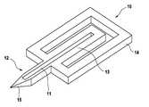
- FIG. 1shows a skin piercing element ( 10 ) which has a fluid pathway ( 11 ) which runs in an elongated portion ( 12 , 13 ) of the skin piercing element.
- This portionis connected to a holder ( 14 ) in form of a frame.
- the elongated portionhas a protruding portion ( 12 ) which protrudes from the holder portion ( 14 ).
- a sharpened tip ( 15 )is located at the front end of the protruding portion.
- the sharpened tip ( 15 )enables penetration of the skin surface during pricking with the skin piercing element.
- the fluid pathway ( 11 )starts in the front end region of the protruding portion and extends into a movable portion ( 13 ) which is located in the holder frame ( 14 ).
- the fluid pathwayis an open capillary channel which permits body fluid which contacts the channel in the region of the protruding portion to move into the moveable portion ( 13 ) by means of capillary action.
- protruding portion, moveable portion and frame portion of the skin piercing elementare formed integrally.
- the skin piercing element ( 10 )can be made by etching processes. As well known in silicon manufacturing processes a wafer of silicon material can be etched to provide devices comprising tips and capillary channels.
- the skin piercing elementsFor mass production it is however advantageous to produce the skin piercing elements by etching of thin metal plates. It is particularly advantageous that the sharpened tip ( 15 ) of the protruding portion ( 12 ) can be formed during the etching process as well so as to avoid separate grinding steps.
- FIG. 1Athere is no reagent or sensor contacting the fluid channel which would receive body fluid immediately after the channel has been filled with sample fluid.
- the present inventioncontrary to that proposes to locate a test zone or sensor separately on a fluid receiving means.
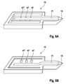
- FIG. 1Bshows the skin piercing element ( 10 ) of FIG. 1A together with a fluid receiving means including a test zone.
- the fluid receiving means ( 40 )is shown schematically.
- the fluid receiving means ( 40 )is located on the upper side of the skin piercing element on which side the fluid channel ( 11 ) is open to the environment.
- the fluid receiving means ( 40 )is, however, initially spaced from the fluid pathway ( 11 ) so that sample fluid within the fluid pathway does not contact the fluid receiving means. Therefore no fluid transfer from the fluid pathway onto the fluid receiving means occurs in this geometry of the fluid sampling device.
- the fluid receiving meansessentially consists of a holding structure ( 41 ) which provides proper orientation and spacing of the fluid receiving means relative to the skin piercing element and three test zones ( 45 , 45 ′, 45 ′′).
- the test zonescomprise different reagent chemistries which produce optical signals based on the concentration of three analytes in the body fluid. Due to the incorporation of porous materials as e.g. kieselghur or titanium dioxid the reagent chemistry already has high capillarity that sucks fluid from capillary channel ( 11 ). The reagent chemistries are applied to a carrier surface. As shown in FIG.
- the fluid pathway and the test zones ( 45 , 45 ′, 45 ′′)are spaced apart so that body fluid located in the capillary channel ( 11 ) will not be transferred to the test zones ( 45 , 45 ′, 45 ′′).
- the body fluid sampling deviceis primed for measurement.
- the moveable section ( 13 )can be bend in direction of the test zones so that body fluid located in the fluid pathway contacts the test zones and wets the reagent chemistries. This mode of contacting the test zones with sample fluid has several advantages over the prior art devices.
- a first advantage over the prior artis that measurement can be initiated at a specific point in time. This means that the time between wetting of the test zones and measurement of the final signal can be chosen at will. The time period, however, is shorter than the drying time of blood in the capillary. Knowing or controlling the time of reaction improves accuracy of the measurement. Further a signal can be measured beginning directly after wetting which allows to monitor reaction kinetics. Evaluation of this early signals can be used to improve accuracy of the measurement result as well.
- FIG. 1BWhen the moveable section ( 13 ) is contacted with the test zones ( 45 , 45 ′, 45 ′′) it contacts an intermediate section of the fluid channel ( 11 ) but not the very end.
- the intermediate portion of the channeltherefore contains fluid almost uncontaminated and without ISF. Since fluid from this region is transferred to the fluid receiving means and therefore needs to be accessible, this region is called the access region.
- This concept of transporting fluid from the capillary to the fluid receiving meansserves to exclude disturbances of measurement by plasma or substances from the skin surface. It goes by its own that contamination by substances from the skin surface should be avoided if possible, in particular, when the amounts of sample for analysis are decreased to low amounts (e.g. below 1 microliter).
- this body fluidnormally does not show the actual blood analyte concentrations but concentrations from 5 to 30 minutes before. This is due to the time delay of exchange between the blood compartment and the interstitial fluid compartment.
- FIG. 1Cshows the moveable portion due to its shape in form of a tongue can be bent upwardly. Based on the very thin structure of the skin piercing element the moveable section automatically will have enough flexibility if the skin piercing element is made from a ductile material. Suitable materials are e.g. metals, silicon and even ceramics which do not brake upon bending.
- FIG. 2 Ashows a second embodiment where contact between the fluid channel and the fluid receiving means is accomplished by a moveable fluid receiving means.
- the skin piercing elementhas a protruding portion ( 12 ) with a tip ( 15 ) for piercing the skin.
- a fluid channel ( 11 ) in form of a capillary channelstarts close to the piercing tip ( 15 ) and extends into an intermediate section of the holder portion ( 14 ).
- the fluid receiving meanscomprises a spacer ( 42 ) and a moveable carrier ( 43 ) fixed to the spacer.
- the moveable carrier ( 43 )at its underside holds two test zones ( 45 , 45 ′) in form of a reagent matrix for optical detection.
- the moveable carrier ( 43 )When the capillary channel ( 11 ) is filled with sample fluid the moveable carrier ( 43 ) is depressed and the test zones ( 45 , 45 ′) contacts the filled channel and take up body fluid. The transparent carrier ( 43 ) now can be illuminated and radiation reflected by the back side of the test zones ( 45 , 45 ′) can be measured to obtain a signal.
- FIG. 2 Bshows the portion of the fluid channel ( 11 ) which contacts the sensors ( 45 , 45 ′) in more detail.
- the channelhas upstanding walls which protrude from the upper surface of the skin piercing element ( 14 ).
- the upstanding walls ( 11 ′)have pointed edges. The function of these edges can better be seen in FIG. 2C which shows the interaction between a test zone and the fluid pathway ( 11 ).
- the left drawing of FIG. 2 Cshows the test zones ( 45 , 45 ′) approaching the fluid pathway.
- the test zones ( 45 , 45 ′)are located at the underside of a carrier ( 40 ).
- the body fluid ( 25 ) residing in the fluid pathway ( 11 )has a depressed conus.
- test zonesmay not be sufficient to contact the body fluid with the testing material.
- the function of the pointed edgescan be seen which serves to depress the sensor material or even to cut it. Due to this the test zones on one hand are approaching the surface of body fluid more closely and on the other hand an intimate contact between the testing material and the channel walls is achieved. Both aspects improve transfer of body fluid from the fluid pathway onto the test zone.
- FIG. 3depicts four embodiments showing cuts through piercing elements and test zones. This will illustrate a technical problem which has to be accounted for.
- a hydrophobic coating16
- FIG. 3 a contact of the test zones with the skin piercing elementdoes not only bring the test zones and body fluid into contact but during the contact capillary spaces are generated between the test zones (or the carrier) on one hand and the portions beside the fluid pathway on the other hand.
- Thisnormally creates a high capillarity which transfers sample fluid residing in the channel not only on the test zones but also into the small capillary spaces which are generated.
- the hydrophobic coating ( 16 )avoids sample fluid from creeping between the upper surface of the skin piercing element ( 14 ) and the carrier or test zones. It is desired to transfer the sample onto a dedicated area of the testing material so that the transferred amounts of sample fluid are sufficient to wet the test zones in a way that an accurate measurement can be achieved. Loosing sample fluid to other regions of the test zones or to the carrier could mean that the testing materials are not wetted sufficiently in the dedicated regions and measurement cannot be conducted properly.
- FIG. 3 bshows a further embodiment which avoids an unintentional creeping of sample fluid.
- this embodimenthas upstanding channel walls which contact the test zones or the carrier. Due to this, fluid that creeps into spaces stops at the outer channel walls and a loss of sample fluid is largely reduced.
- the channel wallsdo not need to be square shaped as depicted in FIG. 3 b but they may also be pointed as shown in FIG. 3 c or 3 d.
- FIG. 4shows the concept of electrical triggering a contact of sample fluid with the test zones.
- This general conceptis shown in FIG. 4 with respect to a skin piercing element as special embodiment of a support structure having a channel.
- a skin piercing elementfor fluid triggering a high potential is applied between the sample fluid ( 25 ) and the carrier ( 40 ). This may cause either sample fluid to move from the channel onto the test zones or may cause a movement of the carrier in direction of the channel. In both cases wetting of the test zones by sample fluid can be triggered in a very short time frame by turning on the electrical potential.
- the channel beneath the test zonesleads into a collecting zone ( 26 ) for providing a larger amount of fluid for wetting the test zones than the thin capillary channel would provide.
- FIG. 4Bdepicts preferred embodiments of collecting zones in more detail.
- the collecting zone ( 26 )preferably has upstanding elements ( 26 ′) which facilitate movement of fluid onto the test zones. These upstanding elements on one hand provoke high electrical charges at their end for transporting fluid and on the other hand they improve capillarity of the collecting zone ( 26 ) which improves filling with fluid.
- FIGS. 5A , B and Cdepict sampler designs for providing skin piercing element and test zones in a spaced apart geometry that allows contacting of test zones with sample fluid in the channel by actuation.
- the embodiment of FIG. 5Ais similar to FIG. 1 .
- the skin piercing elementcomprises a frame which is connected to an inner portion ( 13 ′) in which runs the capillary channel ( 11 ). Inner portion and frame are connected by bendable portions ( 51 ). After filling of the capillary channel the inner portion is torsioned against the frame so that a portion of the capillary contacts the test zones beneath the carrier ( 43 ). By bending around the bendable portions the inner portion contacts the test zones in an angled manner. This has proven to be particularly advantageous since it provides a uniform wetting of the test zones without inclusion of air bubbles.
- FIG. 5Bshows an embodiment where the carrier ( 43 ) and its support are connected via bendable portions ( 51 ′) to a main portion ( 14 ′) which comprises the capillary. Again contact between capillary and test zones is accomplished in a tilted manner.
- FIG. 5Cshows an embodiment having an inner portion ( 13 ′′) which is connected at two ends to the frame portion ( 14 ′′). When pressure is applied from the underside to the central part of the inner portion ( 13 ′′) this bends against the test zones beneath the carrier ( 43 ). By bowing this inner portion again an angled contacting is achieved.
- FIG. 6schematically depicts an improved shape of the capillary channel. It has been found that the fill level of fluid in the channel generally increases with decreasing width of the capillary.
- the capillary of FIG. 6has a first region (a) which leads into the tip portion of the skin piercing element.
- a second region (b) of increased diameteris for providing an increased sample volume.
- Particularly usefulis third region (c) of decreased width. Due to the decreased width the fill level is increased and therefore transfer of fluid from the channel to the test zones has a high success rate. Therefore it is preferred to contact the test zones with the capillary in a tilted manner so that it first contacts region (c) and thereafter region (b). This ensures that fluid transfer will be initiated safely by region (c) and enough sample for testing is provided by region (b).
- Region (d) downstream region (c)may be employed to discharge contaminated sample fluid or ISF.
- FIG. 7shows a skin piercing element having a first region (a) leading into the tip region and a second region (b) of increased diameter.
- Picture Ashows a status after skin has been pierced and blood was taken into region (a) of the capillary channel. Due to lower decreased capillarity of region (b) sample liquid fills region (a) but not region (b).
- the skin piercing elementis contacted with a carrier ( 43 ) the open channel structure (a, b, d) in some portion is closed at its top and capillarity is hence increased in this portion so that collection region (b) is filled and test zones on the underside of the carrier ( 43 ) come into contact with sample fluid. It is advantageous to have a circular detection area with view to the geometry of optical elements.
- a skin piercing element according to FIG. 7may be used in following method:
- FIGS. 8A und 8 Bshow embodiments of skin piercing elements ( 10 ) which are adapted to provide sample fluid to multiple (three in the depicted cases) test zones.
- the fluid pathways ( 11 ) in both figuresstart in the front end region near to the sharpened tip ( 15 ).
- FIGS. 8A and 8Bhave reservoir zones ( 47 , 47 ′, 47 ′′) which serve to hold sample for wetting corresponding test zones when contacted with them.
- the reservoirspreferably have a larger diameter than the capillary channel ( 11 ) so that a larger amount of fluid is stored.
- the reservoir zonesare integrated into the straight fluid pathway ( 11 ) while in FIG.
- sampling elements of the present inventiontherefore may have side fluid channels which branch from the main fluid pathway and reservoirs provided in these side fluid channels. According to this the reservoir zones and hence the contact sites with test zones can be separated spatially to avoid interferences between the contact sites.
Landscapes
- Health & Medical Sciences (AREA)
- Life Sciences & Earth Sciences (AREA)
- Engineering & Computer Science (AREA)
- Physics & Mathematics (AREA)
- Molecular Biology (AREA)
- General Health & Medical Sciences (AREA)
- Biophysics (AREA)
- Biomedical Technology (AREA)
- Heart & Thoracic Surgery (AREA)
- Medical Informatics (AREA)
- Veterinary Medicine (AREA)
- Surgery (AREA)
- Animal Behavior & Ethology (AREA)
- Pathology (AREA)
- Public Health (AREA)
- Hematology (AREA)
- Manufacturing & Machinery (AREA)
- Dermatology (AREA)
- Emergency Medicine (AREA)
- Optics & Photonics (AREA)
- Measurement Of The Respiration, Hearing Ability, Form, And Blood Characteristics Of Living Organisms (AREA)
- Sampling And Sample Adjustment (AREA)
- Investigating Or Analysing Biological Materials (AREA)
Abstract
Description
- sampling body fluid into the sampling element
- transporting sampled body fluid with the sampling element to a fluid receiving means
- contacting the fluid receiving means with body fluid on the sampling element,
- detecting a change of the fluid receiving means which relates to the concentration of two or more analytes.
- introducing fluid into an introduction region of a support structure which has a channel therein, said fluid filling an access region of the support structure which is accessible from the surrounding and the channel having a discharge region located downstream the access region
- contacting a fluid receiving means with fluid located in the access region to receive fluid but not contacting it with fluid in the discharge region.
- piercing skin
- sampling body fluid into a portion of the capillary channel (region (a)).
- contacting the capillary channel in a collecting region (b) with test zones and/or a carrier so that region (b) fills with body fluid
- detecting changes of the test zones due to reaction with analyte from the body fluid.
Claims (33)
Priority Applications (1)
| Application Number | Priority Date | Filing Date | Title |
|---|---|---|---|
| US13/167,243US8369918B2 (en) | 2004-03-06 | 2011-06-23 | Body fluid sampling device |
Applications Claiming Priority (4)
| Application Number | Priority Date | Filing Date | Title |
|---|---|---|---|
| EP04005385 | 2004-03-06 | ||
| EP04005385.2 | 2004-03-06 | ||
| EP04005385 | 2004-03-06 | ||
| PCT/EP2005/002316WO2005084545A1 (en) | 2004-03-06 | 2005-03-04 | Body fluid sampling device |
Related Parent Applications (1)
| Application Number | Title | Priority Date | Filing Date |
|---|---|---|---|
| PCT/EP2005/002316ContinuationWO2005084545A1 (en) | 2004-03-06 | 2005-03-04 | Body fluid sampling device |
Related Child Applications (1)
| Application Number | Title | Priority Date | Filing Date |
|---|---|---|---|
| US13/167,243ContinuationUS8369918B2 (en) | 2004-03-06 | 2011-06-23 | Body fluid sampling device |
Publications (2)
| Publication Number | Publication Date |
|---|---|
| US20060293611A1 US20060293611A1 (en) | 2006-12-28 |
| US8000762B2true US8000762B2 (en) | 2011-08-16 |
Family
ID=34917165
Family Applications (4)
| Application Number | Title | Priority Date | Filing Date |
|---|---|---|---|
| US11/469,123Expired - Fee RelatedUS8000762B2 (en) | 2004-03-06 | 2006-08-31 | Body fluid sampling device |
| US11/470,021Expired - Fee RelatedUS8162854B2 (en) | 2004-03-06 | 2006-09-05 | Body fluid sampling device |
| US13/167,243Expired - Fee RelatedUS8369918B2 (en) | 2004-03-06 | 2011-06-23 | Body fluid sampling device |
| US13/421,163Expired - Fee RelatedUS9022952B2 (en) | 2004-03-06 | 2012-03-15 | Body fluid sampling device |
Family Applications After (3)
| Application Number | Title | Priority Date | Filing Date |
|---|---|---|---|
| US11/470,021Expired - Fee RelatedUS8162854B2 (en) | 2004-03-06 | 2006-09-05 | Body fluid sampling device |
| US13/167,243Expired - Fee RelatedUS8369918B2 (en) | 2004-03-06 | 2011-06-23 | Body fluid sampling device |
| US13/421,163Expired - Fee RelatedUS9022952B2 (en) | 2004-03-06 | 2012-03-15 | Body fluid sampling device |
Country Status (15)
| Country | Link |
|---|---|
| US (4) | US8000762B2 (en) |
| EP (5) | EP2705792B1 (en) |
| JP (3) | JP4602398B2 (en) |
| KR (1) | KR101198054B1 (en) |
| CN (5) | CN1929784B (en) |
| AU (2) | AU2005220022B2 (en) |
| BR (2) | BRPI0508528B8 (en) |
| CA (5) | CA2558086C (en) |
| DK (1) | DK1722670T3 (en) |
| ES (4) | ES2438215T3 (en) |
| HU (1) | HUE025706T2 (en) |
| PL (4) | PL2705792T3 (en) |
| PT (3) | PT1722670E (en) |
| SG (1) | SG153808A1 (en) |
| WO (3) | WO2005084530A2 (en) |
Cited By (7)
| Publication number | Priority date | Publication date | Assignee | Title |
|---|---|---|---|---|
| US20070038149A1 (en)* | 2004-03-06 | 2007-02-15 | Calasso Irio G | Body fluid sampling device |
| US20110009774A1 (en)* | 2004-03-06 | 2011-01-13 | Irio Calasso | Body fluid sampling device |
| US8690797B2 (en) | 2009-06-19 | 2014-04-08 | Roche Diagnostics Operations, Inc. | Piercing system |
| US8802445B2 (en) | 2007-05-04 | 2014-08-12 | Opko Diagnostics, Llc | Fluidic connectors and microfluidic systems |
| US9176090B2 (en) | 2009-04-07 | 2015-11-03 | Panasonic Healthcare Holdings Co., Ltd. | Sensor chip, and measurement device and blood test device in which this sensor chip is used |
| US9827564B2 (en) | 2009-02-02 | 2017-11-28 | Opko Diagnostics, Llc | Fluidic systems and methods for analyses |
| US10672503B2 (en) | 2012-03-05 | 2020-06-02 | Opko Diagnostics, Llc | Methods and apparatuses for conducting analyses |
Families Citing this family (143)
| Publication number | Priority date | Publication date | Assignee | Title |
|---|---|---|---|---|
| US6391005B1 (en) | 1998-03-30 | 2002-05-21 | Agilent Technologies, Inc. | Apparatus and method for penetration with shaft having a sensor for sensing penetration depth |
| US8641644B2 (en) | 2000-11-21 | 2014-02-04 | Sanofi-Aventis Deutschland Gmbh | Blood testing apparatus having a rotatable cartridge with multiple lancing elements and testing means |
| US7749174B2 (en) | 2001-06-12 | 2010-07-06 | Pelikan Technologies, Inc. | Method and apparatus for lancet launching device intergrated onto a blood-sampling cartridge |
| EP1395185B1 (en) | 2001-06-12 | 2010-10-27 | Pelikan Technologies Inc. | Electric lancet actuator |
| JP4209767B2 (en) | 2001-06-12 | 2009-01-14 | ペリカン テクノロジーズ インコーポレイテッド | Self-optimized cutting instrument with adaptive means for temporary changes in skin properties |
| US8337419B2 (en) | 2002-04-19 | 2012-12-25 | Sanofi-Aventis Deutschland Gmbh | Tissue penetration device |
| US9427532B2 (en) | 2001-06-12 | 2016-08-30 | Sanofi-Aventis Deutschland Gmbh | Tissue penetration device |
| US9226699B2 (en) | 2002-04-19 | 2016-01-05 | Sanofi-Aventis Deutschland Gmbh | Body fluid sampling module with a continuous compression tissue interface surface |
| US7041068B2 (en) | 2001-06-12 | 2006-05-09 | Pelikan Technologies, Inc. | Sampling module device and method |
| US7344507B2 (en) | 2002-04-19 | 2008-03-18 | Pelikan Technologies, Inc. | Method and apparatus for lancet actuation |
| US9795747B2 (en) | 2010-06-02 | 2017-10-24 | Sanofi-Aventis Deutschland Gmbh | Methods and apparatus for lancet actuation |
| US7981056B2 (en) | 2002-04-19 | 2011-07-19 | Pelikan Technologies, Inc. | Methods and apparatus for lancet actuation |
| US7004928B2 (en) | 2002-02-08 | 2006-02-28 | Rosedale Medical, Inc. | Autonomous, ambulatory analyte monitor or drug delivery device |
| US7331931B2 (en) | 2002-04-19 | 2008-02-19 | Pelikan Technologies, Inc. | Method and apparatus for penetrating tissue |
| US9248267B2 (en) | 2002-04-19 | 2016-02-02 | Sanofi-Aventis Deustchland Gmbh | Tissue penetration device |
| US8221334B2 (en) | 2002-04-19 | 2012-07-17 | Sanofi-Aventis Deutschland Gmbh | Method and apparatus for penetrating tissue |
| US8372016B2 (en) | 2002-04-19 | 2013-02-12 | Sanofi-Aventis Deutschland Gmbh | Method and apparatus for body fluid sampling and analyte sensing |
| US7232451B2 (en) | 2002-04-19 | 2007-06-19 | Pelikan Technologies, Inc. | Method and apparatus for penetrating tissue |
| US7229458B2 (en) | 2002-04-19 | 2007-06-12 | Pelikan Technologies, Inc. | Method and apparatus for penetrating tissue |
| US7892183B2 (en) | 2002-04-19 | 2011-02-22 | Pelikan Technologies, Inc. | Method and apparatus for body fluid sampling and analyte sensing |
| US9795334B2 (en) | 2002-04-19 | 2017-10-24 | Sanofi-Aventis Deutschland Gmbh | Method and apparatus for penetrating tissue |
| US7297122B2 (en) | 2002-04-19 | 2007-11-20 | Pelikan Technologies, Inc. | Method and apparatus for penetrating tissue |
| US7547287B2 (en) | 2002-04-19 | 2009-06-16 | Pelikan Technologies, Inc. | Method and apparatus for penetrating tissue |
| US7976476B2 (en) | 2002-04-19 | 2011-07-12 | Pelikan Technologies, Inc. | Device and method for variable speed lancet |
| US9314194B2 (en) | 2002-04-19 | 2016-04-19 | Sanofi-Aventis Deutschland Gmbh | Tissue penetration device |
| US8579831B2 (en) | 2002-04-19 | 2013-11-12 | Sanofi-Aventis Deutschland Gmbh | Method and apparatus for penetrating tissue |
| US8360992B2 (en) | 2002-04-19 | 2013-01-29 | Sanofi-Aventis Deutschland Gmbh | Method and apparatus for penetrating tissue |
| US8784335B2 (en) | 2002-04-19 | 2014-07-22 | Sanofi-Aventis Deutschland Gmbh | Body fluid sampling device with a capacitive sensor |
| US7708701B2 (en) | 2002-04-19 | 2010-05-04 | Pelikan Technologies, Inc. | Method and apparatus for a multi-use body fluid sampling device |
| US8702624B2 (en) | 2006-09-29 | 2014-04-22 | Sanofi-Aventis Deutschland Gmbh | Analyte measurement device with a single shot actuator |
| US7491178B2 (en) | 2002-04-19 | 2009-02-17 | Pelikan Technologies, Inc. | Method and apparatus for penetrating tissue |
| US7909778B2 (en) | 2002-04-19 | 2011-03-22 | Pelikan Technologies, Inc. | Method and apparatus for penetrating tissue |
| US7901362B2 (en) | 2002-04-19 | 2011-03-08 | Pelikan Technologies, Inc. | Method and apparatus for penetrating tissue |
| US8267870B2 (en) | 2002-04-19 | 2012-09-18 | Sanofi-Aventis Deutschland Gmbh | Method and apparatus for body fluid sampling with hybrid actuation |
| US7674232B2 (en) | 2002-04-19 | 2010-03-09 | Pelikan Technologies, Inc. | Method and apparatus for penetrating tissue |
| US7815579B2 (en) | 2005-03-02 | 2010-10-19 | Roche Diagnostics Operations, Inc. | Dynamic integrated lancing test strip with sterility cover |
| US7214200B2 (en) | 2002-12-30 | 2007-05-08 | Roche Diagnostics Operations, Inc. | Integrated analytical test element |
| US8574895B2 (en) | 2002-12-30 | 2013-11-05 | Sanofi-Aventis Deutschland Gmbh | Method and apparatus using optical techniques to measure analyte levels |
| US7211052B2 (en) | 2002-12-30 | 2007-05-01 | Roche Diagnostics Operations, Inc. | Flexible test strip lancet device |
| US7052652B2 (en) | 2003-03-24 | 2006-05-30 | Rosedale Medical, Inc. | Analyte concentration detection devices and methods |
| DE602004028463D1 (en) | 2003-05-30 | 2010-09-16 | Pelikan Technologies Inc | METHOD AND DEVICE FOR INJECTING LIQUID |
| US7850621B2 (en) | 2003-06-06 | 2010-12-14 | Pelikan Technologies, Inc. | Method and apparatus for body fluid sampling and analyte sensing |
| WO2006001797A1 (en) | 2004-06-14 | 2006-01-05 | Pelikan Technologies, Inc. | Low pain penetrating |
| US7920906B2 (en) | 2005-03-10 | 2011-04-05 | Dexcom, Inc. | System and methods for processing analyte sensor data for sensor calibration |
| US8282576B2 (en) | 2003-09-29 | 2012-10-09 | Sanofi-Aventis Deutschland Gmbh | Method and apparatus for an improved sample capture device |
| EP1680014A4 (en) | 2003-10-14 | 2009-01-21 | Pelikan Technologies Inc | METHOD AND DEVICE FOR A VARIABLE USER INTERFACE |
| US9247900B2 (en) | 2004-07-13 | 2016-02-02 | Dexcom, Inc. | Analyte sensor |
| US8668656B2 (en) | 2003-12-31 | 2014-03-11 | Sanofi-Aventis Deutschland Gmbh | Method and apparatus for improving fluidic flow and sample capture |
| US7822454B1 (en) | 2005-01-03 | 2010-10-26 | Pelikan Technologies, Inc. | Fluid sampling device with improved analyte detecting member configuration |
| WO2006011062A2 (en) | 2004-05-20 | 2006-02-02 | Albatros Technologies Gmbh & Co. Kg | Printable hydrogel for biosensors |
| WO2005120365A1 (en) | 2004-06-03 | 2005-12-22 | Pelikan Technologies, Inc. | Method and apparatus for a fluid sampling device |
| US9775553B2 (en) | 2004-06-03 | 2017-10-03 | Sanofi-Aventis Deutschland Gmbh | Method and apparatus for a fluid sampling device |
| US7654956B2 (en) | 2004-07-13 | 2010-02-02 | Dexcom, Inc. | Transcutaneous analyte sensor |
| US20070045902A1 (en) | 2004-07-13 | 2007-03-01 | Brauker James H | Analyte sensor |
| US7488298B2 (en) | 2004-10-08 | 2009-02-10 | Roche Diagnostics Operations, Inc. | Integrated lancing test strip with capillary transfer sheet |
| EP1654985A1 (en)* | 2004-11-09 | 2006-05-10 | F. Hoffmann-La Roche Ag | Sampling device for sample liquid |
| US8652831B2 (en)* | 2004-12-30 | 2014-02-18 | Sanofi-Aventis Deutschland Gmbh | Method and apparatus for analyte measurement test time |
| US20090054811A1 (en)* | 2004-12-30 | 2009-02-26 | Dirk Boecker | Method and apparatus for analyte measurement test time |
| US20060281187A1 (en) | 2005-06-13 | 2006-12-14 | Rosedale Medical, Inc. | Analyte detection devices and methods with hematocrit/volume correction and feedback control |
| EP1759633A1 (en) | 2005-09-01 | 2007-03-07 | F.Hoffmann-La Roche Ag | Device for sampling bodily fluids and its fabrication method |
| US8801631B2 (en) | 2005-09-30 | 2014-08-12 | Intuity Medical, Inc. | Devices and methods for facilitating fluid transport |
| EP1928302B1 (en) | 2005-09-30 | 2012-08-01 | Intuity Medical, Inc. | Fully integrated wearable or handheld monitor |
| EP1933695B1 (en)* | 2005-10-15 | 2015-05-27 | F. Hoffmann-La Roche AG | Test element and test system for examining a body fluid |
| EP1839576A1 (en) | 2006-03-29 | 2007-10-03 | F.Hoffmann-La Roche Ag | Test system with test unit for analysing body fluids |
| US20090093735A1 (en)* | 2006-03-29 | 2009-04-09 | Stephan Korner | Test unit and test system for analyzing body fluids |
| EP1878386A1 (en)* | 2006-07-15 | 2008-01-16 | Roche Diagnostics GmbH | Process to produce lancet; lancet, lancet band and device for pricking the skin |
| EP1878387B1 (en) | 2006-07-15 | 2010-11-24 | Roche Diagnostics GmbH | Lancet, lancet feeder belt and pricking device for creating a puncture wound |
| DE502006007846D1 (en)* | 2006-07-18 | 2010-10-21 | Roche Diagnostics Gmbh | lancet |
| EP1894526A1 (en)* | 2006-09-04 | 2008-03-05 | F. Hoffmann-la Roche AG | Lancet |
| US8852124B2 (en)* | 2006-10-13 | 2014-10-07 | Roche Diagnostics Operations, Inc. | Tape transport lance sampler |
| EP1911394B1 (en) | 2006-10-14 | 2009-05-06 | Roche Diagnostics GmbH | Lancet with capillar channel |
| EP1977686A1 (en) | 2007-04-04 | 2008-10-08 | F.Hoffmann-La Roche Ag | Disposable diagnostic article |
| US20110092854A1 (en) | 2009-10-20 | 2011-04-21 | Uwe Kraemer | Instruments and system for producing a sample of a body fluid and for analysis thereof |
| BRPI0810862B8 (en) | 2007-04-30 | 2021-06-22 | Hoffmann La Roche | system for producing a body fluid sample through skin piercing |
| EP2150177B1 (en) | 2007-05-29 | 2018-04-25 | Roche Diabetes Care GmbH | Test system for measuring the concentration of an analyte in a body fluid |
| EP2025287A1 (en) | 2007-08-16 | 2009-02-18 | F.Hoffmann-La Roche Ag | Diagnostic disposable part and method for its production |
| EP2205152B1 (en)* | 2007-09-17 | 2011-11-23 | F. Hoffmann-La Roche AG | Disposable device for analyzing body fluid |
| WO2009046957A2 (en)* | 2007-10-08 | 2009-04-16 | Roche Diagnostics Gmbh | Analysis system for automatic skin prick analysis |
| ATE488179T1 (en)* | 2007-10-12 | 2010-12-15 | Hoffmann La Roche | TEST BAND DEVICE FOR EXAMINING BODY FLUID |
| KR101009447B1 (en) | 2007-11-12 | 2011-01-19 | 바디텍메드 주식회사 | Body fluid sampling, pretreatment and dosing device and method |
| US7766846B2 (en) | 2008-01-28 | 2010-08-03 | Roche Diagnostics Operations, Inc. | Rapid blood expression and sampling |
| AU2013202929B2 (en)* | 2008-01-28 | 2016-05-26 | F. Hoffmann-La Roche Ag | System for detection of an analyte in a body fluid |
| EP2087840A1 (en)* | 2008-02-11 | 2009-08-12 | F.Hoffmann-La Roche Ag | Device and method for removing bodily fluids |
| EP2093284A1 (en) | 2008-02-19 | 2009-08-26 | F.Hoffmann-La Roche Ag | Stabilisation of dehydrogenases with stable coenzymes |
| EP2252196A4 (en) | 2008-02-21 | 2013-05-15 | Dexcom Inc | Systems and methods for processing, transmitting and displaying sensor data |
| EP3616618B1 (en)* | 2008-03-05 | 2022-11-30 | Becton, Dickinson and Company | Capillary action collection device |
| EP2265324B1 (en) | 2008-04-11 | 2015-01-28 | Sanofi-Aventis Deutschland GmbH | Integrated analyte measurement system |
| USD586465S1 (en) | 2008-05-09 | 2009-02-10 | Lifescan Scotland Limited | Handheld lancing device |
| USD586916S1 (en) | 2008-05-09 | 2009-02-17 | Lifescan Scotland, Ltd. | Handheld lancing device |
| US9833183B2 (en) | 2008-05-30 | 2017-12-05 | Intuity Medical, Inc. | Body fluid sampling device—sampling site interface |
| EP3984454A1 (en) | 2008-06-06 | 2022-04-20 | Intuity Medical, Inc. | Medical diagnostic devices and methods |
| WO2009148624A1 (en) | 2008-06-06 | 2009-12-10 | Intuity Medical, Inc. | Detection meter and mode of operation |
| EP2316339A4 (en)* | 2008-08-01 | 2012-10-24 | Lightnix Inc | Sensor with fine needle having channel formed therein |
| US8118824B2 (en)* | 2008-09-16 | 2012-02-21 | Roche Diagnostics Operations, Inc. | Magnetic powered lancing drive |
| EP2181651A1 (en)* | 2008-10-29 | 2010-05-05 | Roche Diagnostics GmbH | Instrument and system for producing a sample of a body liquid and for analysis thereof |
| NZ591742A (en)* | 2008-11-07 | 2012-12-21 | Hoffmann La Roche | Fine-grained filler substances for photometric reaction films |
| EP2208459A1 (en)* | 2009-01-16 | 2010-07-21 | F. Hoffmann-Roche AG | System and method for analysing a body fluid |
| US9375169B2 (en) | 2009-01-30 | 2016-06-28 | Sanofi-Aventis Deutschland Gmbh | Cam drive for managing disposable penetrating member actions with a single motor and motor and control system |
| EP2218400A1 (en) | 2009-02-12 | 2010-08-18 | Roche Diagnostics GmbH | Lance with test area |
| KR101604624B1 (en) | 2009-02-19 | 2016-03-28 | 에프. 호프만-라 로슈 아게 | Fast reaction kinetics of enzymes having low activity in dry chemistry layers |
| EP2398909B1 (en) | 2009-02-19 | 2015-07-22 | F. Hoffmann-La Roche AG | Fast reaction kinetics of enzymes having low activity in dry chemistry layers |
| EP2241252A1 (en)* | 2009-03-17 | 2010-10-20 | F. Hoffmann-La Roche AG | Testing device, in particular for blood sugar tests |
| EP2272429A1 (en) | 2009-07-10 | 2011-01-12 | Roche Diagnostics GmbH | Lancet |
| EP2283774A1 (en) | 2009-08-13 | 2011-02-16 | Roche Diagnostics GmbH | Test element for analysing a body fluid |
| EP2287605A1 (en) | 2009-08-20 | 2011-02-23 | Roche Diagnostics GmbH | Simplified magazining of integrated systems |
| EP2322924A1 (en) | 2009-10-15 | 2011-05-18 | F. Hoffmann-La Roche AG | Protection from hydrophobic agents |
| WO2011048200A2 (en) | 2009-10-22 | 2011-04-28 | Roche Diagnostics Gmbh | Micro-capillary system having increased sample volume |
| CN102068262B (en)* | 2009-11-23 | 2012-11-21 | 财团法人金属工业研究发展中心 | Sampling device with flexible compression zone |
| EP2506768B1 (en) | 2009-11-30 | 2016-07-06 | Intuity Medical, Inc. | Calibration material delivery devices and methods |
| EP2333544A1 (en) | 2009-12-11 | 2011-06-15 | F. Hoffmann-La Roche AG | Sterilisable chemistry for test elements |
| CA2782943C (en) | 2009-12-16 | 2014-09-09 | F. Hoffmann-La Roche Ag | Detecting the decomposition of enzymes in a test element by means of controlled release of a protected analyte |
| US8965476B2 (en) | 2010-04-16 | 2015-02-24 | Sanofi-Aventis Deutschland Gmbh | Tissue penetration device |
| EP2382921A1 (en) | 2010-04-30 | 2011-11-02 | Roche Diagnostics GmbH | Lancing device with automatic disengagement |
| CA2803797A1 (en) | 2010-06-25 | 2011-12-29 | Intuity Medical, Inc. | Analyte monitoring methods and systems |
| EP2417910B1 (en)* | 2010-08-11 | 2013-06-26 | Roche Diagnostics GmbH | Analytical test unit and test system |
| TWI532530B (en)* | 2010-10-29 | 2016-05-11 | 萬國商業機器公司 | Multilayer microfluidic probe head with immersion channels and fabrication thereof |
| TWI532468B (en)* | 2011-03-22 | 2016-05-11 | 福 赫夫曼 拉瑞奇股份有限公司 | Analytical aid with hydrophilic coating containing nanoparticles with silica structure |
| EP2520225B1 (en)* | 2011-05-06 | 2014-05-21 | Roche Diagnostics GmbH | Lancet |
| US9782114B2 (en) | 2011-08-03 | 2017-10-10 | Intuity Medical, Inc. | Devices and methods for body fluid sampling and analysis |
| MX353252B (en)* | 2011-09-23 | 2018-01-05 | Hoffmann La Roche | Method for the mask-etching of a piercing element. |
| US20130211289A1 (en) | 2012-01-25 | 2013-08-15 | Tasso, Inc. | Handheld Device for Drawing, Collecting, and Analyzing Bodily Fluid |
| EP2874942B1 (en) | 2012-07-23 | 2018-09-05 | Tasso, Inc. | Methods and devices relating to open microfluidic channels |
| EP2892496B1 (en)* | 2012-09-06 | 2017-06-28 | Theranos, Inc. | Devices for bodily fluid sample collection |
| US20150320348A1 (en)* | 2012-11-16 | 2015-11-12 | Lightstat, Llc | Disposable sample collection method and apparatus |
| EP2777499B1 (en)* | 2013-03-15 | 2015-09-16 | Ortho-Clinical Diagnostics Inc | Rotatable fluid sample collection device |
| US9523653B2 (en) | 2013-05-09 | 2016-12-20 | Changsha Sinocare Inc. | Disposable test sensor with improved sampling entrance |
| WO2014205412A1 (en) | 2013-06-21 | 2014-12-24 | Intuity Medical, Inc. | Analyte monitoring system with audible feedback |
| US9518951B2 (en) | 2013-12-06 | 2016-12-13 | Changsha Sinocare Inc. | Disposable test sensor with improved sampling entrance |
| US9897566B2 (en) | 2014-01-13 | 2018-02-20 | Changsha Sinocare Inc. | Disposable test sensor |
| TWI548395B (en)* | 2014-01-28 | 2016-09-11 | 微凸科技股份有限公司 | Continuous percutaneous microneedle monitoring system |
| US9939401B2 (en) | 2014-02-20 | 2018-04-10 | Changsha Sinocare Inc. | Test sensor with multiple sampling routes |
| US10779757B2 (en)* | 2014-08-01 | 2020-09-22 | Tasso, Inc. | Devices, systems and methods for gravity-enhanced microfluidic collection, handling and transferring of fluids |
| CN106999120B (en) | 2014-08-01 | 2021-05-14 | 塔索公司 | Devices, systems, and methods for gravity-enhanced microfluidic collection, handling, and delivery of liquids |
| CN104874098B (en)* | 2015-04-08 | 2018-04-10 | 上海交通大学 | A kind of hollow metal micropin and its batch preparation |
| CN105738462A (en)* | 2016-02-24 | 2016-07-06 | 长沙金域医学检验所有限公司 | Detection method for microelements in peripheral blood |
| EP3711670B1 (en)* | 2016-05-04 | 2022-03-16 | midge medical GmbH | Body fluid extraction device |
| CN106137223B (en)* | 2016-08-12 | 2019-04-26 | 上海移宇科技股份有限公司 | One-step fully integrated body fluid sampling analyzer |
| US10596591B2 (en)* | 2017-01-04 | 2020-03-24 | Red Devil Inc. | Material dispensing system and method |
| CN108968982B (en)* | 2018-06-07 | 2024-08-02 | 杭州博拓生物科技股份有限公司 | Device for detecting analyte in sample |
| USD967402S1 (en)* | 2019-06-05 | 2022-10-18 | Aidian Oy | Blood collecting device |
| CN118169205A (en)* | 2019-08-20 | 2024-06-11 | 深圳硅基传感科技有限公司 | Method for preparing working electrode of glucose sensor |
| CN111956237B (en)* | 2020-07-31 | 2023-03-24 | 江苏麦酷博信息科技有限公司 | RFID blood collection card |
| US12054334B2 (en) | 2021-11-19 | 2024-08-06 | Red Devil, Inc. | Sausage package dispensing system, device and method |
Citations (57)
| Publication number | Priority date | Publication date | Assignee | Title |
|---|---|---|---|---|
| GB1418337A (en) | 1972-04-28 | 1975-12-17 | Harco Electr Ltd | Measurement of fluid on pieces of wettable material |
| US4218421A (en) | 1978-08-18 | 1980-08-19 | Honeywell Inc. | Disposable container for a continuous band of test strips |
| EP0458405A2 (en) | 1990-05-22 | 1991-11-27 | Eastman Kodak Company | Liquid collection and separation devices |
| US5108889A (en)* | 1988-10-12 | 1992-04-28 | Thorne, Smith, Astill Technologies, Inc. | Assay for determining analyte using mercury release followed by detection via interaction with aluminum |
| US5163442A (en)* | 1991-07-30 | 1992-11-17 | Harry Ono | Finger tip blood collector |
| EP0199484B1 (en) | 1985-04-08 | 1993-03-17 | Audio Bionics Inc | Medical system |
| EP0299517B1 (en) | 1987-07-15 | 1993-10-06 | Fuji Photo Film Co., Ltd. | Long-test-film cassette for biochemical analysis |
| US5318514A (en) | 1992-08-17 | 1994-06-07 | Btx, Inc. | Applicator for the electroporation of drugs and genes into surface cells |
| US5582184A (en)* | 1993-10-13 | 1996-12-10 | Integ Incorporated | Interstitial fluid collection and constituent measurement |
| WO1997018036A1 (en) | 1995-11-13 | 1997-05-22 | Cortecs (Uk) Limited | Diagnostic test apparatus |
| EP0565970B1 (en) | 1992-04-13 | 1997-09-24 | Boehringer Mannheim Gmbh | Blood lancet device for obtaining blood samples for diagnosis purpose |
| WO1997042888A1 (en) | 1996-05-17 | 1997-11-20 | Mercury Diagnostics Inc. | Blood and interstitial fluid sampling device |
| US5762770A (en)* | 1994-02-21 | 1998-06-09 | Boehringer Mannheim Corporation | Electrochemical biosensor test strip |
| US5801057A (en) | 1996-03-22 | 1998-09-01 | Smart; Wilson H. | Microsampling device and method of construction |
| USRE36268E (en) | 1988-03-15 | 1999-08-17 | Boehringer Mannheim Corporation | Method and apparatus for amperometric diagnostic analysis |
| US6063040A (en)* | 1998-01-16 | 2000-05-16 | Specialized Health Products, Inc. | Self retracting needle apparatus and method for phlebotomy |
| US6132449A (en)* | 1999-03-08 | 2000-10-17 | Agilent Technologies, Inc. | Extraction and transportation of blood for analysis |
| EP1101443A2 (en) | 1999-11-17 | 2001-05-23 | Bayer Corporation | Electronic lancing device |
| WO2001066010A1 (en) | 2000-03-04 | 2001-09-13 | Roche Diagnostics Gmbh | Blood lancet with hygienic tip protection |
| WO2001072220A1 (en) | 2000-03-27 | 2001-10-04 | Usf Filtration And Separations Group, Inc. | Method and device for sampling and analyzing interstitial fluid and whole blood samples |
| WO2002007503A1 (en) | 2000-07-25 | 2002-01-31 | The Regents Of The University Of California | Electrowetting-driven micropumping |
| US20020043463A1 (en) | 2000-08-31 | 2002-04-18 | Alexander Shenderov | Electrostatic actuators for microfluidics and methods for using same |
| US6375626B1 (en) | 1999-03-12 | 2002-04-23 | Integ, Inc. | Collection well for body fluid tester |
| WO2002050534A1 (en) | 2000-12-19 | 2002-06-27 | Inverness Medical Limited | Device for measuring blood coagulation and method thereof |
| WO2002062210A1 (en) | 2001-02-06 | 2002-08-15 | Roche Diagnostics Gmbh | System, for monitoring the concentration of analytes in body fluids |
| US20020114715A1 (en) | 2001-02-20 | 2002-08-22 | Korea Advanced Institute Of Science And Technology | Micropump driven by movement of liquid drop induced by continuous electrowetting |
| US20020168290A1 (en) | 2002-05-09 | 2002-11-14 | Yuzhakov Vadim V. | Physiological sample collection devices and methods of using the same |
| WO2002100253A2 (en) | 2001-06-12 | 2002-12-19 | Pelikan Technologies, Inc. | Blood sampling device with diaphragm actuated lancet |
| US20030018282A1 (en) | 2001-07-20 | 2003-01-23 | Carlo Effenhauser | System for withdrawing small amounts of body fluid |
| US20030028125A1 (en)* | 2001-08-06 | 2003-02-06 | Yuzhakov Vadim V. | Physiological sample collection devices and methods of using the same |
| US20030059350A1 (en) | 1998-04-24 | 2003-03-27 | Klaus-Dieter Sacherer | Storage container for analytical devices |
| US20030073931A1 (en)* | 2001-10-16 | 2003-04-17 | Dirk Boecker | Universal diagnostic platform |
| US20030083685A1 (en) | 2001-06-12 | 2003-05-01 | Freeman Dominique M. | Sampling module device and method |
| US6589260B1 (en) | 2000-05-26 | 2003-07-08 | Roche Diagnostics Corporation | System for withdrawing body fluid |
| US20030135333A1 (en) | 2000-06-27 | 2003-07-17 | Rosedale Medical, Inc. | Analyte Monitor |
| EP1360934A1 (en) | 2002-05-09 | 2003-11-12 | Lifescan, Inc. | Devices and methods for accessing and analyzing physiological fluid |
| EP1360933A1 (en) | 2002-05-09 | 2003-11-12 | Lifescan, Inc. | Physiological sample collection devices and methods of using the same |
| US6660018B2 (en) | 1999-03-08 | 2003-12-09 | Agilent Technologies, Inc. | Multiple lancet device |
| EP1371419A1 (en)* | 2002-06-12 | 2003-12-17 | F. Hoffmann-La Roche AG | Method and device for detecting the presence of an analyte in a test sample |
| US20040022681A1 (en) | 2002-08-05 | 2004-02-05 | Palo Alto Research Center Incorporated | Capillary-channel probes for liquid pickup, transportation and dispense using stressy metal |
| US20040064068A1 (en) | 2002-09-30 | 2004-04-01 | Denuzzio John D. | Integrated lancet and bodily fluid sensor |
| EP1424040A1 (en) | 2002-11-26 | 2004-06-02 | Roche Diagnostics GmbH | Body fluid testing device |
| US20040176732A1 (en) | 2000-06-02 | 2004-09-09 | Frazier A Bruno | Active needle devices with integrated functionality |
| US20040193072A1 (en)* | 2003-03-28 | 2004-09-30 | Allen John J. | Method of analyte measurement using integrated lance and strip |
| US6821483B2 (en) | 1986-08-13 | 2004-11-23 | Lifescan, Inc. | Reagents test strip with alignment notch |
| EP1508304A1 (en) | 2003-08-13 | 2005-02-23 | Lifescan, Inc. | Packaged medical device with a deployable dermal tissue penetration member |
| US20050043597A1 (en) | 2003-07-31 | 2005-02-24 | Skymoon Research And Development, Llc | Optical vivo probe of analyte concentration within the sterile matrix under the human nail |
| US20050149088A1 (en) | 2003-12-19 | 2005-07-07 | Mitsuo Fukuda | Medical lancet |
| WO2005084546A2 (en) | 2004-03-06 | 2005-09-15 | Roche Diagnostics Gmbh | Body fluid sampling device |
| US20050234368A1 (en) | 2004-04-15 | 2005-10-20 | Daniel Wong | Integrated spot monitoring device with fluid sensor |
| US6988996B2 (en)* | 2001-06-08 | 2006-01-24 | Roche Diagnostics Operatons, Inc. | Test media cassette for bodily fluid testing device |
| US20060087064A1 (en) | 2004-10-27 | 2006-04-27 | Palo Alto Research Center Incorporated | Oblique parts or surfaces |
| US20060276724A1 (en) | 2003-06-13 | 2006-12-07 | Freeman Dominique M | Method and apparatus for a point of care device |
| US20070016103A1 (en) | 2004-03-06 | 2007-01-18 | Irio Calasso | Body fluid sampling device |
| US20070126536A1 (en) | 2005-12-02 | 2007-06-07 | Palo Alto Research Center Incorporated | Electromechanical switch |
| US20070250099A1 (en) | 2004-07-20 | 2007-10-25 | Flora Bruce A | Multiple Tip Lancet |
| US20080268669A1 (en) | 2003-12-19 | 2008-10-30 | Palo Alto Research Center Incorporated | Transferable Micro Spring Structure |
Family Cites Families (40)
| Publication number | Priority date | Publication date | Assignee | Title |
|---|---|---|---|---|
| US6268A (en)* | 1849-04-03 | James h | ||
| US2728343A (en) | 1954-06-03 | 1955-12-27 | S & R J Everett & Co Ltd | Sewing needles |
| JPH0810207B2 (en)* | 1989-11-08 | 1996-01-31 | 日本特殊陶業株式会社 | Biosensor |
| US5172701A (en) | 1990-02-28 | 1992-12-22 | Medical Device Technologies, Inc. | Single use automated soft tissue aspiration biopsy device |
| US5591139A (en)* | 1994-06-06 | 1997-01-07 | The Regents Of The University Of California | IC-processed microneedles |
| US5644177A (en) | 1995-02-23 | 1997-07-01 | Wisconsin Alumni Research Foundation | Micromechanical magnetically actuated devices |
| CN1207056A (en)* | 1995-11-13 | 1999-02-03 | 科特克斯(英国)有限公司 | Diagnostic Test Equipment |
| DK0921840T3 (en) | 1996-07-03 | 2003-09-22 | Altea Therapeutics Corp | Multiple mechanical microperforation of skin or mucosa |
| US6486947B2 (en) | 1998-07-22 | 2002-11-26 | Ljl Biosystems, Inc. | Devices and methods for sample analysis |
| US5931794A (en) | 1997-10-21 | 1999-08-03 | Pitesky; Isadore | Allergy testing apparatus |
| DE19824036A1 (en)* | 1997-11-28 | 1999-06-02 | Roche Diagnostics Gmbh | Analytical measuring device with lancing device |
| US6214030B1 (en) | 1998-08-10 | 2001-04-10 | Mani, Inc. | Suture needle |
| US6252195B1 (en) | 1999-04-26 | 2001-06-26 | Ethicon, Inc. | Method of forming blind holes in surgical needles using a diode pumped Nd-YAG laser |
| EP1078602A3 (en) | 1999-08-26 | 2001-04-04 | Mani, Inc. | Suturing needle for medical use |
| US7499745B2 (en) | 2000-02-28 | 2009-03-03 | Barbara Ann Karmanos Cancer Institute | Multidimensional bioelectrical tissue analyzer |
| ES2420279T3 (en) | 2000-03-02 | 2013-08-23 | Microchips, Inc. | Microfabricated devices and methods for storage and selective exposure of chemicals |
| US6506168B1 (en)* | 2000-05-26 | 2003-01-14 | Abbott Laboratories | Apparatus and method for obtaining blood for diagnostic tests |
| EP1203563A3 (en) | 2000-10-31 | 2004-01-02 | Boehringer Mannheim Gmbh | Analyzing mean with integrated lancet |
| US20030196695A1 (en) | 2000-11-06 | 2003-10-23 | Nanostream, Inc. | Microfluidic flow control devices |
| US6638246B1 (en) | 2000-11-28 | 2003-10-28 | Scimed Life Systems, Inc. | Medical device for delivery of a biologically active material to a lumen |
| US9302903B2 (en) | 2000-12-14 | 2016-04-05 | Georgia Tech Research Corporation | Microneedle devices and production thereof |
| US6793632B2 (en) | 2001-06-12 | 2004-09-21 | Lifescan, Inc. | Percutaneous biological fluid constituent sampling and measurement devices and methods |
| US7344507B2 (en)* | 2002-04-19 | 2008-03-18 | Pelikan Technologies, Inc. | Method and apparatus for lancet actuation |
| US6875613B2 (en) | 2001-06-12 | 2005-04-05 | Lifescan, Inc. | Biological fluid constituent sampling and measurement devices and methods |
| US6837988B2 (en) | 2001-06-12 | 2005-01-04 | Lifescan, Inc. | Biological fluid sampling and analyte measurement devices and methods |
| US20030028087A1 (en) | 2001-08-01 | 2003-02-06 | Yuzhakov Vadim Vladimirovich | Devices for analyte concentration determination and methods of using the same |
| SE0102736D0 (en) | 2001-08-14 | 2001-08-14 | Patrick Griss | Side opened out-of-plane microneedles for microfluidic transdermal interfacing and fabrication process of side opened out-of-plane microneedles |
| AU2002357166A1 (en) | 2001-12-12 | 2003-06-23 | Tissuelink Medical, Inc. | Fluid-assisted medical devices, systems and methods |
| US6840909B2 (en) | 2002-03-25 | 2005-01-11 | Acueity, Inc. | Apparatus and method for intraductal cytology |
| ATE376800T1 (en) | 2002-05-31 | 2007-11-15 | Facet Technologies Llc | PRECISE GUIDED LANCET |
| US20030223906A1 (en) | 2002-06-03 | 2003-12-04 | Mcallister Devin | Test strip container system |
| ATE385741T1 (en) | 2002-07-26 | 2008-03-15 | Stuart B Brown | TISSUE AND FLUID COLLECTION DEVICE |
| WO2004024224A1 (en) | 2002-09-16 | 2004-03-25 | Sung-Yun Kwon | Solid micro-perforators and methods of use |
| US6989234B2 (en)* | 2002-09-24 | 2006-01-24 | Duke University | Method and apparatus for non-contact electrostatic actuation of droplets |
| DE10327683A1 (en) | 2003-06-20 | 2005-01-20 | Bayer Technology Services Gmbh | Method and device for the quantitative electrical detection of analytes |
| US20060047309A1 (en) | 2004-08-25 | 2006-03-02 | Cichocki Frank R Jr | Metal injection molded suture needles |
| JP2006119401A (en) | 2004-10-22 | 2006-05-11 | Seiko Epson Corp | Method and apparatus for manufacturing electro-optical device, electro-optical device, and electronic apparatus |
| US20070270738A1 (en) | 2005-04-25 | 2007-11-22 | Wu Jeffrey M | Method of treating ACNE with stratum corneum piercing patch |
| EP1928302B1 (en) | 2005-09-30 | 2012-08-01 | Intuity Medical, Inc. | Fully integrated wearable or handheld monitor |
| US7766846B2 (en) | 2008-01-28 | 2010-08-03 | Roche Diagnostics Operations, Inc. | Rapid blood expression and sampling |
- 2005
- 2005-03-04PTPT57157166Tpatent/PT1722670E/enunknown
- 2005-03-04DKDK05715716.6Tpatent/DK1722670T3/enactive
- 2005-03-04CNCN200580007255XApatent/CN1929784B/ennot_activeExpired - Fee Related
- 2005-03-04CNCN2009101795128Apatent/CN101690665B/ennot_activeExpired - Fee Related
- 2005-03-04JPJP2007501232Apatent/JP4602398B2/ennot_activeExpired - Fee Related
- 2005-03-04KRKR1020067016887Apatent/KR101198054B1/ennot_activeExpired - Fee Related
- 2005-03-04BRBRPI0508528Apatent/BRPI0508528B8/ennot_activeIP Right Cessation
- 2005-03-04CACA2558086Apatent/CA2558086C/ennot_activeExpired - Fee Related
- 2005-03-04WOPCT/EP2005/002273patent/WO2005084530A2/enactiveApplication Filing
- 2005-03-04PTPT131835803Tpatent/PT2705792E/enunknown
- 2005-03-04HUHUE13183580Apatent/HUE025706T2/enunknown
- 2005-03-04ESES05715716.6Tpatent/ES2438215T3/ennot_activeExpired - Lifetime
- 2005-03-04CACA2773645Apatent/CA2773645C/ennot_activeExpired - Fee Related
- 2005-03-04PLPL13183580Tpatent/PL2705792T3/enunknown
- 2005-03-04ESES13183580.3Tpatent/ES2541680T3/ennot_activeExpired - Lifetime
- 2005-03-04EPEP13183580.3Apatent/EP2705792B1/ennot_activeExpired - Lifetime
- 2005-03-04CNCNB2005800072564Apatent/CN100563561C/ennot_activeExpired - Fee Related
- 2005-03-04EPEP05715745.5Apatent/EP1725168B1/ennot_activeExpired - Lifetime
- 2005-03-04EPEP05715716.6Apatent/EP1722670B1/ennot_activeExpired - Lifetime
- 2005-03-04PLPL05715716Tpatent/PL1722670T3/enunknown
- 2005-03-04CACA2557966Apatent/CA2557966C/ennot_activeExpired - Fee Related
- 2005-03-04AUAU2005220022Apatent/AU2005220022B2/ennot_activeExpired
- 2005-03-04JPJP2007501224Apatent/JP4917013B2/ennot_activeExpired - Fee Related
- 2005-03-04WOPCT/EP2005/002316patent/WO2005084545A1/ennot_activeApplication Discontinuation
- 2005-03-04PLPL05715745.5Tpatent/PL1725168T3/enunknown
- 2005-03-04ESES05715745.5Tpatent/ES2572775T3/ennot_activeExpired - Lifetime
- 2005-03-07CNCNA2005800072545Apatent/CN1929783A/enactivePending
- 2005-03-07CACA2837991Apatent/CA2837991C/ennot_activeExpired - Fee Related
- 2005-03-07PLPL05715775Tpatent/PL1725169T3/enunknown
- 2005-03-07JPJP2007501237Apatent/JP4959545B2/ennot_activeExpired - Fee Related
- 2005-03-07AUAU2005220027Apatent/AU2005220027B2/ennot_activeExpired
- 2005-03-07SGSG200903875-3Apatent/SG153808A1/enunknown
- 2005-03-07WOPCT/EP2005/002357patent/WO2005084546A2/ennot_activeApplication Discontinuation
- 2005-03-07EPEP05715775.2Apatent/EP1725169B1/ennot_activeExpired - Lifetime
- 2005-03-07BRBRPI0508515Apatent/BRPI0508515B8/ennot_activeIP Right Cessation
- 2005-03-07PTPT57157752Tpatent/PT1725169E/enunknown
- 2005-03-07EPEP13004756.6Apatent/EP2727531A3/ennot_activeWithdrawn
- 2005-03-07CNCN201310004560.XApatent/CN103126689B/ennot_activeExpired - Fee Related
- 2005-03-07ESES05715775.2Tpatent/ES2470979T3/ennot_activeExpired - Lifetime
- 2005-03-07CACA2558121Apatent/CA2558121C/ennot_activeExpired - Fee Related
- 2006
- 2006-08-31USUS11/469,123patent/US8000762B2/ennot_activeExpired - Fee Related
- 2006-09-05USUS11/470,021patent/US8162854B2/ennot_activeExpired - Fee Related
- 2011
- 2011-06-23USUS13/167,243patent/US8369918B2/ennot_activeExpired - Fee Related
- 2012
- 2012-03-15USUS13/421,163patent/US9022952B2/ennot_activeExpired - Fee Related
Patent Citations (73)
| Publication number | Priority date | Publication date | Assignee | Title |
|---|---|---|---|---|
| GB1418337A (en) | 1972-04-28 | 1975-12-17 | Harco Electr Ltd | Measurement of fluid on pieces of wettable material |
| US4218421A (en) | 1978-08-18 | 1980-08-19 | Honeywell Inc. | Disposable container for a continuous band of test strips |
| EP0199484B1 (en) | 1985-04-08 | 1993-03-17 | Audio Bionics Inc | Medical system |
| US6821483B2 (en) | 1986-08-13 | 2004-11-23 | Lifescan, Inc. | Reagents test strip with alignment notch |
| EP0299517B1 (en) | 1987-07-15 | 1993-10-06 | Fuji Photo Film Co., Ltd. | Long-test-film cassette for biochemical analysis |
| USRE36268E (en) | 1988-03-15 | 1999-08-17 | Boehringer Mannheim Corporation | Method and apparatus for amperometric diagnostic analysis |
| US5108889A (en)* | 1988-10-12 | 1992-04-28 | Thorne, Smith, Astill Technologies, Inc. | Assay for determining analyte using mercury release followed by detection via interaction with aluminum |
| EP0458405A2 (en) | 1990-05-22 | 1991-11-27 | Eastman Kodak Company | Liquid collection and separation devices |
| US5163442A (en)* | 1991-07-30 | 1992-11-17 | Harry Ono | Finger tip blood collector |
| EP0565970B1 (en) | 1992-04-13 | 1997-09-24 | Boehringer Mannheim Gmbh | Blood lancet device for obtaining blood samples for diagnosis purpose |
| US5318514A (en) | 1992-08-17 | 1994-06-07 | Btx, Inc. | Applicator for the electroporation of drugs and genes into surface cells |
| EP0723418B1 (en) | 1993-10-13 | 1999-01-07 | Integ Incorporated | Interstitial fluid collection and constituent measurement |
| US5582184A (en)* | 1993-10-13 | 1996-12-10 | Integ Incorporated | Interstitial fluid collection and constituent measurement |
| US5762770A (en)* | 1994-02-21 | 1998-06-09 | Boehringer Mannheim Corporation | Electrochemical biosensor test strip |
| WO1997018036A1 (en) | 1995-11-13 | 1997-05-22 | Cortecs (Uk) Limited | Diagnostic test apparatus |
| US5801057A (en) | 1996-03-22 | 1998-09-01 | Smart; Wilson H. | Microsampling device and method of construction |
| WO1997042888A1 (en) | 1996-05-17 | 1997-11-20 | Mercury Diagnostics Inc. | Blood and interstitial fluid sampling device |
| US6063040A (en)* | 1998-01-16 | 2000-05-16 | Specialized Health Products, Inc. | Self retracting needle apparatus and method for phlebotomy |
| US20030059350A1 (en) | 1998-04-24 | 2003-03-27 | Klaus-Dieter Sacherer | Storage container for analytical devices |
| US6132449A (en)* | 1999-03-08 | 2000-10-17 | Agilent Technologies, Inc. | Extraction and transportation of blood for analysis |
| US6660018B2 (en) | 1999-03-08 | 2003-12-09 | Agilent Technologies, Inc. | Multiple lancet device |
| US6364890B1 (en) | 1999-03-08 | 2002-04-02 | Agilent Technologies, Inc. | Extraction and transportation of blood for analysis |
| US6375626B1 (en) | 1999-03-12 | 2002-04-23 | Integ, Inc. | Collection well for body fluid tester |
| EP1101443A2 (en) | 1999-11-17 | 2001-05-23 | Bayer Corporation | Electronic lancing device |
| WO2001066010A1 (en) | 2000-03-04 | 2001-09-13 | Roche Diagnostics Gmbh | Blood lancet with hygienic tip protection |
| WO2001072220A1 (en) | 2000-03-27 | 2001-10-04 | Usf Filtration And Separations Group, Inc. | Method and device for sampling and analyzing interstitial fluid and whole blood samples |
| CN1431884A (en) | 2000-03-27 | 2003-07-23 | 生命扫描有限公司 | Method and device for sampling and analyzing interstitial fluid and whole blood samples |
| US6612111B1 (en) | 2000-03-27 | 2003-09-02 | Lifescan, Inc. | Method and device for sampling and analyzing interstitial fluid and whole blood samples |
| US6589260B1 (en) | 2000-05-26 | 2003-07-08 | Roche Diagnostics Corporation | System for withdrawing body fluid |
| US20040176732A1 (en) | 2000-06-02 | 2004-09-09 | Frazier A Bruno | Active needle devices with integrated functionality |
| US20030135333A1 (en) | 2000-06-27 | 2003-07-17 | Rosedale Medical, Inc. | Analyte Monitor |
| US20030205632A1 (en)* | 2000-07-25 | 2003-11-06 | Chang-Jin Kim | Electrowetting-driven micropumping |
| WO2002007503A1 (en) | 2000-07-25 | 2002-01-31 | The Regents Of The University Of California | Electrowetting-driven micropumping |
| US20020043463A1 (en) | 2000-08-31 | 2002-04-18 | Alexander Shenderov | Electrostatic actuators for microfluidics and methods for using same |
| WO2002050534A1 (en) | 2000-12-19 | 2002-06-27 | Inverness Medical Limited | Device for measuring blood coagulation and method thereof |
| WO2002049507A1 (en) | 2000-12-19 | 2002-06-27 | Inverness Medical Limited | Analyte measurement |
| US7005857B2 (en)* | 2000-12-19 | 2006-02-28 | Lifescan Scotland Limited | Device for measuring blood coagulation and method thereof |
| WO2002062210A1 (en) | 2001-02-06 | 2002-08-15 | Roche Diagnostics Gmbh | System, for monitoring the concentration of analytes in body fluids |
| US20020114715A1 (en) | 2001-02-20 | 2002-08-22 | Korea Advanced Institute Of Science And Technology | Micropump driven by movement of liquid drop induced by continuous electrowetting |
| US6988996B2 (en)* | 2001-06-08 | 2006-01-24 | Roche Diagnostics Operatons, Inc. | Test media cassette for bodily fluid testing device |
| US20030083685A1 (en) | 2001-06-12 | 2003-05-01 | Freeman Dominique M. | Sampling module device and method |
| WO2002100253A2 (en) | 2001-06-12 | 2002-12-19 | Pelikan Technologies, Inc. | Blood sampling device with diaphragm actuated lancet |
| US20030018282A1 (en) | 2001-07-20 | 2003-01-23 | Carlo Effenhauser | System for withdrawing small amounts of body fluid |
| US20030028125A1 (en)* | 2001-08-06 | 2003-02-06 | Yuzhakov Vadim V. | Physiological sample collection devices and methods of using the same |
| CN1407327A (en) | 2001-08-06 | 2003-04-02 | 生命扫描有限公司 | Physiologically sample collecting device and its use method thereof |
| US20030073931A1 (en)* | 2001-10-16 | 2003-04-17 | Dirk Boecker | Universal diagnostic platform |
| US20040260204A1 (en) | 2001-10-16 | 2004-12-23 | Agilent Technologies, Inc. | Universal diagnostic platform |
| US20030212344A1 (en) | 2002-05-09 | 2003-11-13 | Vadim Yuzhakov | Physiological sample collection devices and methods of using the same |
| EP1360933A1 (en) | 2002-05-09 | 2003-11-12 | Lifescan, Inc. | Physiological sample collection devices and methods of using the same |
| EP1360931A1 (en) | 2002-05-09 | 2003-11-12 | Lifescan, Inc. | Physiological sample collection devices and method of using the same |
| EP1360934A1 (en) | 2002-05-09 | 2003-11-12 | Lifescan, Inc. | Devices and methods for accessing and analyzing physiological fluid |
| US20020168290A1 (en) | 2002-05-09 | 2002-11-14 | Yuzhakov Vadim V. | Physiological sample collection devices and methods of using the same |
| EP1371419A1 (en)* | 2002-06-12 | 2003-12-17 | F. Hoffmann-La Roche AG | Method and device for detecting the presence of an analyte in a test sample |
| US20040022681A1 (en) | 2002-08-05 | 2004-02-05 | Palo Alto Research Center Incorporated | Capillary-channel probes for liquid pickup, transportation and dispense using stressy metal |
| US20040064068A1 (en) | 2002-09-30 | 2004-04-01 | Denuzzio John D. | Integrated lancet and bodily fluid sensor |
| EP1424040A1 (en) | 2002-11-26 | 2004-06-02 | Roche Diagnostics GmbH | Body fluid testing device |
| US20040193072A1 (en)* | 2003-03-28 | 2004-09-30 | Allen John J. | Method of analyte measurement using integrated lance and strip |
| US20060276724A1 (en) | 2003-06-13 | 2006-12-07 | Freeman Dominique M | Method and apparatus for a point of care device |
| US20050043597A1 (en) | 2003-07-31 | 2005-02-24 | Skymoon Research And Development, Llc | Optical vivo probe of analyte concentration within the sterile matrix under the human nail |
| EP1508304A1 (en) | 2003-08-13 | 2005-02-23 | Lifescan, Inc. | Packaged medical device with a deployable dermal tissue penetration member |
| US20050149088A1 (en) | 2003-12-19 | 2005-07-07 | Mitsuo Fukuda | Medical lancet |
| US20060100654A1 (en) | 2003-12-19 | 2006-05-11 | Mitsuo Fukuda | Medical needle and medical device |
| US20080268669A1 (en) | 2003-12-19 | 2008-10-30 | Palo Alto Research Center Incorporated | Transferable Micro Spring Structure |
| WO2005084545A1 (en) | 2004-03-06 | 2005-09-15 | Roche Diagnostics Gmbh | Body fluid sampling device |
| WO2005084530A2 (en) | 2004-03-06 | 2005-09-15 | F. Hoffmann-La Roche Ag | Body fluid sampling device |
| WO2005084546A3 (en) | 2004-03-06 | 2006-03-02 | Roche Diagnostics Gmbh | Body fluid sampling device |
| WO2005084546A2 (en) | 2004-03-06 | 2005-09-15 | Roche Diagnostics Gmbh | Body fluid sampling device |
| US20070016103A1 (en) | 2004-03-06 | 2007-01-18 | Irio Calasso | Body fluid sampling device |
| US20070038149A1 (en) | 2004-03-06 | 2007-02-15 | Calasso Irio G | Body fluid sampling device |
| US20050234368A1 (en) | 2004-04-15 | 2005-10-20 | Daniel Wong | Integrated spot monitoring device with fluid sensor |
| US20070250099A1 (en) | 2004-07-20 | 2007-10-25 | Flora Bruce A | Multiple Tip Lancet |
| US20060087064A1 (en) | 2004-10-27 | 2006-04-27 | Palo Alto Research Center Incorporated | Oblique parts or surfaces |
| US20070126536A1 (en) | 2005-12-02 | 2007-06-07 | Palo Alto Research Center Incorporated | Electromechanical switch |
Non-Patent Citations (7)
| Title |
|---|
| English translation-in-part of Japanese Unexamined Patent Publication No. 150458/1991. |
| Final Office Action received in related U.S. Appl. No. 11/470,021, mailed Sep. 8, 2009. |
| Final Office Action received in related U.S. Appl. No. 11/470,368, mailed Jun. 11, 2009. |
| Non-Final Office Action received in related U.S. Appl. No. 11/470,021, mailed Feb. 27, 2009. |
| Non-Final Office Action received in related U.S. Appl. No. 11/470,368, mailed Dec. 24, 2009. |
| Non-Final Office Action received in related U.S. Appl. No. 11/470,368, mailed Nov. 14, 2008. |
| U.S. Appl. No. 11/470,021 to Calasso et al., Non-Final Office Action mailed Oct. 21, 2010. |
Cited By (17)
| Publication number | Priority date | Publication date | Assignee | Title |
|---|---|---|---|---|
| US20070038149A1 (en)* | 2004-03-06 | 2007-02-15 | Calasso Irio G | Body fluid sampling device |
| US20110009774A1 (en)* | 2004-03-06 | 2011-01-13 | Irio Calasso | Body fluid sampling device |
| US8162854B2 (en) | 2004-03-06 | 2012-04-24 | Roche Diagnostics Operations, Inc. | Body fluid sampling device |
| US8814808B2 (en) | 2004-03-06 | 2014-08-26 | Roche Diagnostics Operations, Inc. | Body fluid sampling device |
| US9022952B2 (en) | 2004-03-06 | 2015-05-05 | Roche Diagnostics Operations, Inc. | Body fluid sampling device |
| US10775369B2 (en) | 2007-05-04 | 2020-09-15 | Opko Diagnostics, Llc | Fluidic systems for analyses |
| US8802445B2 (en) | 2007-05-04 | 2014-08-12 | Opko Diagnostics, Llc | Fluidic connectors and microfluidic systems |
| US9075047B2 (en) | 2007-05-04 | 2015-07-07 | Opko Diagnostics, Llc | Fluidic connectors and microfluidic systems |
| US10408824B2 (en) | 2007-05-04 | 2019-09-10 | Opko Diagnostics, Llc | Fluidic connectors and microfluidic systems |
| US9234888B2 (en) | 2007-05-04 | 2016-01-12 | Opko Diagnostics, Llc | Fluidic connectors and microfluidic systems |
| US9827564B2 (en) | 2009-02-02 | 2017-11-28 | Opko Diagnostics, Llc | Fluidic systems and methods for analyses |
| US9827563B2 (en) | 2009-02-02 | 2017-11-28 | Opko Diagnostics, Llc | Fluidic systems and methods for analyses |
| US9513249B2 (en) | 2009-04-07 | 2016-12-06 | Panasonic Healthcare Holdings Co., Ltd. | Sensor chip, and measurement device and blood test device in which this sensor chip is used |
| US9255902B2 (en) | 2009-04-07 | 2016-02-09 | Panasonic Healthcare Holdings Co., Ltd. | Sensor chip, and measurement device and blood test device in which this sensor chip is used |
| US9176090B2 (en) | 2009-04-07 | 2015-11-03 | Panasonic Healthcare Holdings Co., Ltd. | Sensor chip, and measurement device and blood test device in which this sensor chip is used |
| US8690797B2 (en) | 2009-06-19 | 2014-04-08 | Roche Diagnostics Operations, Inc. | Piercing system |
| US10672503B2 (en) | 2012-03-05 | 2020-06-02 | Opko Diagnostics, Llc | Methods and apparatuses for conducting analyses |
Also Published As
Similar Documents
| Publication | Publication Date | Title |
|---|---|---|
| US8000762B2 (en) | Body fluid sampling device | |
| US8814808B2 (en) | Body fluid sampling device | |
| CN1307420C (en) | Test strip device for physiological samples | |
| HK1104439B (en) | Body fluid sampling device | |
| HK1105847B (en) | Body fluid sampling device | |
| HK1142790B (en) | Body fluid sampling device | |
| MXPA06009307A (en) | Body fluid sampling device |
Legal Events
| Date | Code | Title | Description |
|---|---|---|---|
| AS | Assignment | Owner name:ROCHE DIAGNOSTICS OPERATIONS, INC., INDIANA Free format text:ASSIGNMENT OF ASSIGNORS INTEREST;ASSIGNOR:HASKER, DAVE;REEL/FRAME:018265/0034 Effective date:20060914 | |
| AS | Assignment | Owner name:ROCHE DIAGNOSTICS GMBH, GERMANY Free format text:ASSIGNMENT OF ASSIGNORS INTEREST;ASSIGNORS:CALASSO, IRIO GUISEPPE;GRISS, PATRICK;SAROFIM, EMAD;AND OTHERS;SIGNING DATES FROM 20060922 TO 20061023;REEL/FRAME:018455/0476 Owner name:ROCHE DIAGNOSTICS OPERATIONS, INC., INDIANA Free format text:ASSIGNMENT OF ASSIGNORS INTEREST;ASSIGNOR:ROCHE DIAGNOSTICS GMBH;REEL/FRAME:018455/0491 Effective date:20061024 Owner name:ROCHE DIAGNOSTICS GMBH, GERMANY Free format text:ASSIGNMENT OF ASSIGNORS INTEREST;ASSIGNORS:CALASSO, IRIO GUISEPPE;GRISS, PATRICK;SAROFIM, EMAD;AND OTHERS;REEL/FRAME:018455/0476;SIGNING DATES FROM 20060922 TO 20061023 | |
| ZAAA | Notice of allowance and fees due | Free format text:ORIGINAL CODE: NOA | |
| ZAAB | Notice of allowance mailed | Free format text:ORIGINAL CODE: MN/=. | |
| STCF | Information on status: patent grant | Free format text:PATENTED CASE | |
| FPAY | Fee payment | Year of fee payment:4 | |
| AS | Assignment | Owner name:ROCHE DIABETES CARE, INC., INDIANA Free format text:ASSIGNMENT OF ASSIGNORS INTEREST;ASSIGNOR:ROCHE DIAGNOSTICS OPERATIONS, INC.;REEL/FRAME:036008/0670 Effective date:20150302 | |
| MAFP | Maintenance fee payment | Free format text:PAYMENT OF MAINTENANCE FEE, 8TH YEAR, LARGE ENTITY (ORIGINAL EVENT CODE: M1552); ENTITY STATUS OF PATENT OWNER: LARGE ENTITY Year of fee payment:8 | |
| FEPP | Fee payment procedure | Free format text:MAINTENANCE FEE REMINDER MAILED (ORIGINAL EVENT CODE: REM.); ENTITY STATUS OF PATENT OWNER: LARGE ENTITY | |
| LAPS | Lapse for failure to pay maintenance fees | Free format text:PATENT EXPIRED FOR FAILURE TO PAY MAINTENANCE FEES (ORIGINAL EVENT CODE: EXP.); ENTITY STATUS OF PATENT OWNER: LARGE ENTITY | |
| STCH | Information on status: patent discontinuation | Free format text:PATENT EXPIRED DUE TO NONPAYMENT OF MAINTENANCE FEES UNDER 37 CFR 1.362 | |
| FP | Lapsed due to failure to pay maintenance fee | Effective date:20230816 |